handleiding 8000 en v103 - domeinflits · user's manual johannus organs preface...
TRANSCRIPT

User's manual
JOHANNUS
OPUS
Sweelinck
Rembrandt
Monarke
User's manual JOHANNUS Organs
FCC Compliance Statement This equipment has been tested and found to comply with the limits for a Class B digital device, pursuant to Part 15 of the FCC Rules. These limits are designed to provide reasonable protection against harmful interference in a residential installation. This equipment generates, uses and can radiate radio frequency energy and, if not installed and used in accordance with the instructions, may cause harmful interference to radio communications. However, there is no guarantee that interference will not occur in a particular installation. If this equipment does cause harmful interference to radio or television reception, which can be determined by turning the equipment off and on, the user is encouraged to try to correct the interference by one or more of the following measures: • Reorient or relocate the receiving antenna. • Increase the separation between the equipment and receiver. • Connect the equipment into an outlet on a circuit different from that to which the receiver is
connected. • Consult the dealer or an experienced radio/TV technician for help.
Document data
Document Code handleiding_8000_EN_V103
Document Title User's manual JOHANNUS organs 8000-series
Issue date September 2004
Serienummer © Copyright 2002 JOHANNUS Orgelbouw b.v. Nederland. All rights reserved. No part of this publication may be reproduced and/or published by print, microfilm, audiotape, electronically, mechanically or any other means, or stored in an information retrieval system, without prior written permission from JOHANNUS Orgelbouw b.v.. The information in this document is subject to change without notice and should not be considered a commitment by JOHANNUS Orgelbouw b.v..No responsibility is assumed for any error which may appear in this document.

User's manual JOHANNUS Organs
Preface Congratulations on your decision to purchase a new JOHANNUS organ. JOHANNUS appreciates your patronage and welcomes you to our family of customers. You have now become the owner of an instrument with a tremendous sonority and unknown possibilities. We, the builders of this instrument, would be pleased to help you explore these properties. Quite often a JOHANNUS organ is built to owner's specifications, producing a great diversity in JOHANNUS organs. As you will understand, it is hardly possible to make a manual that fits your specific instrument. To enable you to get to know all the possibilities of your instrument, we have decided to write a manual describing all the functions a JOHANNUS organ may have. Therefore it is possible that you will not find all the functions mentioned in this manual in your instrument. It is also possible that descriptions of certain functions show little discrepancies compared to the controls of your instrument. Usually this pertains to functions which you, the client, commissioned to have altered. As JOHANNUS organs are continually being developed as a result of new wishes of clients, and increasing technical possibilities, a manual like this cannot possibly keep up with this and you may look for the description of a certain function in vain. Should this happen, you can always contact us, so that we may supplement this. This user's manual contains all kinds of useful information. We will first explore the instrument, after that we will put it into use and finally we will go through all the possibilities. In a number of chapters we will enter at length into selecting an intonation, usage of the capture system, the application of MIDI, etc.
User's manual JOHANNUS Organs
Table of contents An overview ................................................................................................................................. 1
Models................................................................................................................................. 1 Opus-series ......................................................................................................... 1 Sweelinck-series.................................................................................................. 1 Rembrandt-series ................................................................................................ 1 Models "Van Rhijn" (Monarke) and "Gothique" ................................................... 2 Model "Positief".................................................................................................... 2 Monarke-model "Van Eyck"................................................................................. 2 Monarke-model "Vermeer" .................................................................................. 3 Monarke-model "Van Gogh"................................................................................ 3 Monarke-Custom ................................................................................................. 3
Type of wood....................................................................................................................... 3 The organ bench................................................................................................................. 4 The keyboards .................................................................................................................... 4
Synthetic keyboards ............................................................................................ 4 Synthetic keyboards with wooden key covering.................................................. 4 Wooden keyboards.............................................................................................. 4
The pedalboard................................................................................................................... 4 The music desk................................................................................................................... 5
Separate music desk ........................................................................................... 5 Fixed music desk................................................................................................. 5 Solid music desk with spare ................................................................................ 5 Hinged music desk .............................................................................................. 5 Tilting music desk ................................................................................................ 6 Horizontally adjustable music desk ..................................................................... 6 Horizontally and vertically adjustable music desk (optional) ............................... 7
Locking up........................................................................................................................... 7 The rol top cover.................................................................................................. 7 Top lid with glass doors ....................................................................................... 8 Keyboard cover.................................................................................................... 9
Stops ................................................................................................................................. 10 Wooden drawstops............................................................................................ 10 Lighted drawstops.............................................................................................. 11 Lighted rocker tabs ............................................................................................ 11 Moving drawstops.............................................................................................. 11
Set up ......................................................................................................................................... 12 Connecting the organ........................................................................................................ 12 Switching on...................................................................................................................... 12 Pedalboard lighting and music desk lighting..................................................................... 13
The console in detail................................................................................................................. 14 Standards.......................................................................................................................... 14 Order of stops ................................................................................................................... 14
Standards .......................................................................................................... 14 Available space and symmetry.......................................................................... 14 Position of accessories...................................................................................... 16 Order of stops.................................................................................................... 16
Order of keyboards ........................................................................................................... 17 Order of expression pedals............................................................................................... 17
User's manual JOHANNUS Organs
Thumb pistons................................................................................................................... 18 0-piston .............................................................................................................. 19 1 - 8.................................................................................................................... 19 – and +............................................................................................................... 19 ANC. OFF.......................................................................................................... 20 CAN. = Cancel................................................................................................... 20 CF = Cantus Firmus .......................................................................................... 20 CH = Chorus...................................................................................................... 20 Couplers ............................................................................................................ 20 CR = General Crescendo .................................................................................. 20 FA = Fix Accessories......................................................................................... 20 HR = Hand registration...................................................................................... 21 INT2 = Intonation 2 ............................................................................................ 22 KT = Keyboard transfer ..................................................................................... 22 M1 and M2......................................................................................................... 22 MB = Manual Bass ............................................................................................ 22 MIDI’s................................................................................................................. 22 MT = Meantone ................................................................................................. 22 PGM = Programming General crescendo and MIDI-stops................................ 22 PIPE ON ............................................................................................................ 22 PP - T = Pianissimo to Tutti inclusive ................................................................ 23 REC. = Recall (undo last change) ..................................................................... 24 RO = Reeds off.................................................................................................. 24 SEQ (sequence) ................................................................................................ 24 SEQ– en SEQ+ (sequence) .............................................................................. 25 SET.................................................................................................................... 26 S/S ..................................................................................................................... 26 TRANS. = Transposer ....................................................................................... 26 Tremulants......................................................................................................... 26 TUNE = Pitch..................................................................................................... 26 VOL. = Volume .................................................................................................. 26 WM = Werckmeister III ...................................................................................... 26
Couplers............................................................................................................................ 27 Manual couplers ................................................................................................ 27 Pedal couplers ................................................................................................... 27 Sub- and super couplers ................................................................................... 27 Cantus Firmus ................................................................................................... 28 Manual Bass ...................................................................................................... 28
Tremulants ........................................................................................................................ 28 Other accessories ............................................................................................................. 29
Chorus ............................................................................................................... 29 Intonation 2 ........................................................................................................ 29 Meantone........................................................................................................... 29 MIDI-stops ......................................................................................................... 29 Unisono off......................................................................................................... 29 Werckmeister III................................................................................................. 30 Wind pressure stabilization................................................................................ 30
Toe pistons........................................................................................................................ 30 COUPLER-pistons............................................................................................. 30 TUTTI-piston...................................................................................................... 30 CAPTURE-pistons............................................................................................. 30 SEQ– and SEQ+-pistons................................................................................... 31 (32')-stop-pistons ............................................................................................... 31
Displays............................................................................................................................. 31 7-segment display.............................................................................................. 31 LCD-display ....................................................................................................... 32 Expression pedal indicators............................................................................... 33
Memory lock...................................................................................................................... 34

User's manual JOHANNUS Organs
Volume controls ................................................................................................................ 34 Expression pedals ............................................................................................. 34 Rotary controls keyboard volume...................................................................... 35 General volume ................................................................................................. 35 Volume acoustics............................................................................................... 36
Pitch settings..................................................................................................................... 37 Fine tuning ......................................................................................................... 37 Transposer......................................................................................................... 38
Acoustics........................................................................................................................... 39 ACOUSTICS (volume)....................................................................................... 40 LENGTH ............................................................................................................ 40
External connections......................................................................................................... 40 MIDI IN............................................................................................................... 40 MIDI MOD.......................................................................................................... 40 MIDI SEQ........................................................................................................... 40 AUX IN............................................................................................................... 41 AUX OUT........................................................................................................... 41 EXT. REV. ......................................................................................................... 41 PHONES............................................................................................................ 41 LOUDSPEAKER CONNECTIONS.................................................................... 41
Choise of temperament ............................................................................................................ 43 Equal temperament........................................................................................................... 43 Werckmeister III temperament.......................................................................................... 43 Meantone temperament.................................................................................................... 43
Using the capture system ........................................................................................................ 44 What are capture combinations? ...................................................................................... 44 Programming capture combinations ................................................................................. 44
Capture system without a display...................................................................... 45 Capture system with 7-segment display............................................................ 45 Capture system with LCD.................................................................................. 46
Recalling capture combinations........................................................................................ 47 Capture system without a display...................................................................... 47 Capture system with 7-segment display............................................................ 47 Capture system with LCD.................................................................................. 47
Using the general crescendo ................................................................................................... 48 Switching on general crescendo....................................................................................... 48 Changing stop combinations general crescendo.............................................................. 49
General crescendo system with 7-segment display .......................................... 49 General crescendo system with LCD ................................................................ 50
Resetting standard stop combinations general crescendo............................................... 51 General crescendo system with 7-segment display .......................................... 51 General crescendo systeem with LCD .............................................................. 51
Application of MIDI.................................................................................................................... 53 What is MIDI?.................................................................................................................... 53 How and what to connect?................................................................................................ 53
Programming MIDI-stops ......................................................................................................... 54 Programming (hand registrations) .................................................................................... 54
Programming MIDI-stops with 7-segment display............................................. 55 Programming MIDI-stops with LCD................................................................... 56
Programming (into the capture system)............................................................................ 58 Programming MIDI-stops with 7-segment display............................................. 58 Programming MIDI-stops with LCD................................................................... 60 Programming several MIDI-stops into the capture system ............................... 62
User's manual JOHANNUS Organs
Sound reproduction systems .................................................................................................. 64 Internal single reproduction system .................................................................................. 64 Internal double reproduction system................................................................................. 64 External single reproduction system................................................................................. 64 External double reproduction system ............................................................................... 64 Internal with external reproduction system ....................................................................... 65 Three position switch ........................................................................................................ 65 Switchboard ...................................................................................................................... 65 Antiphonal ......................................................................................................................... 65
Special functions thumb pistons............................................................................................. 66 Resetting factory intonation .............................................................................................. 66 Clearing the capture memory............................................................................................ 66 Resetting standard MIDI-stop settings.............................................................................. 67 Resetting standard fixed (preset) combinations ............................................................... 67 Transmitting memory content (MIDI dump) ...................................................................... 68
Maintenance............................................................................................................................... 69 Cabinet.............................................................................................................................. 69 Keyboards ......................................................................................................................... 69 Pipes ................................................................................................................................. 69
Warranty..................................................................................................................................... 69
Information................................................................................................................................. 70
MIDI Implementation chart ....................................................................................................... 71
MIDI specifications.................................................................................................................... 72 Default basic channels (transmitted/recognized).............................................................. 72 Basic channel changes (transmitted)................................................................................ 72 Control changes (transmitted)........................................................................................... 72 Control changes (recognized)........................................................................................... 73 Program changes (transmitted) ........................................................................................ 73 Program changes (recognized)......................................................................................... 73 System exclusive messages (transmitted/recognized)..................................................... 73
All stops off ........................................................................................................ 73 Thumb piston values ......................................................................................... 73
Other MIDI-codes (transmitted) ........................................................................................ 73
Registration ............................................................................................................................... 74 Flues ................................................................................................................................. 74
Principals ........................................................................................................... 74 Flutes ................................................................................................................. 74 Strings................................................................................................................ 74
Reeds................................................................................................................................ 74

User's manual JOHANNUS Organs
User's manual JOHANNUS Organs
- 1 -
An overview Models
In addition to the various standard series (Opus, Sweelinck, Rembrandt and Monarke) JOHANNUS Orgelbouw b.v. may have built an instrument exactly geared to your wishes. Usually the starting point is one of the basic models. Below follows a brief description of these basic models. In this user's manual we may refer back to one of these basic models when describing certain controls. Opus-series The Opus series comprises six models. The smallest instrument, the Opus 1, is a 1-manual instrument without a pedalboard. A separate supplement covers a number of special functions only found in this instrument. The Opus 5, 10, 20 and 25 are 2-manual instruments with a full pedalboard. The Opus 5 and the Opus 10 may be designed with a 13-note pedalboard. Of these 2-manual instruments the Opus 5 has the smallest and the Opus 25 the largest disposition. The largest instrument in this series, the Opus 30, is a 3-manual instrument with a 30-note pedalboard. The stops are designed as lighted rocker tabs. The loudspeakers are under the keyboard shelf and reflecting forward. The instruments of this series may be fitted with an extra facility to connect an external loudspeaker front. Sweelinck-series The Sweelinck series comprises three models. Two 2-manual instruments (Sweelinck 10 and Sweelinck 20) and one 3-manual instrument (Sweelinck 30). Just like with the Opus models the stops are designed as lighted rocker tabs. The loudspeakers are under the keyboard shelf and reflecting forward. Also the instruments of this series may be fitted with an extra facility to connect an external loudspeaker front. Rembrandt-series The Rembrandt series comprises four BDO-models and four AGO-models. Two 2-manual instruments (Rembrandt 2070-BDO and 2900-AGO), four 3-manual instruments (Rembrandt 3070-BDO, 3090-BDO, 370-AGO and 3900-AGO) and two 4-manual instrument (Rembrandt 4090-BDO and 4900-AGO). In this series of instruments the speaking stops are designed as lighted draw stops whereas the accessories (usually) are designed as lighted rocker tabs.
User's manual JOHANNUS Organs
- 2 -
Typically the Rembrandt BDO-models are equipped with loudspeakers under the keyboard shelf which are reflecting forward. The Rembrandt AGO-models are designed for connecting to an external loudspeaker front. Models "Van Rhijn" (Monarke) and "Gothique" These 2-manual instruments are designed as cabinets consisting of two or three parts. All the control functions are concealed behind the music desk. The stops are designed as wooden drawstops. Alternatively the stops may be lighted or movable drawstops or lighted rocker tabs. The instrument may be fitted with loudspeakers reflecting forwards as well as backwards. The front loudspeaker panel is finished with a pipe facade or wooden slats. This pipe front is divided into three sections and is covered with triangular panels on the top and bottom. Model "Positief" This 2- or 3-manual instrument may consist of one or two parts. All the controls are concealed behind the pedalboard light cover and / or behind the light cover of the music desk. Typically the stops are designed as wooden drawstops. Alternatively the stops may be lighted or movable drawstops or lighted rocker tabs. The instrument is fitted with loudspeakers reflecting up(wards). Dit 2- of 3-manuaals instrument kan gebouwd zijn als een uit één geheel bestaand meubel of opgebouwd zijn als tweedelig meubel. Monarke-model "Van Eyck" This 2- or 3-manual instrument consists of a main cabinet topped by five loudspeaker boxes. All the controls are concealed behind the pedalboard light cover and / or behind the light cover of the music desk. The stops are designed as wooden drawstops. Alternatively the stops may be lighted or movable drawstops or lighted rocker tabs. The instrument may be fitted with loudspeakers reflecting forwards as well as backwards. The five loudspeaker boxes are finished with pipes or with wooden slats. The five loudspeaker boxes on the main cabinet make up a front consisting of five sections. These sections are covered with round arches at the top.

User's manual JOHANNUS Organs
- 3 -
Monarke-model "Vermeer" This 2- or 3-manual instrument consists of a console of the model "Vermeer" and a separate loudspeaker front, possibly in combination with a number of monitor loudspeakers built in the console. The stops are designed as lighted or movable drawstops. Often the accessories are designed as lighted rocker tabs which are located under the music desk . The console can be locked with a rolltop cover. This model is also available in a luxurious, richly decorated console. The keyboard of this luxury console has no rolltop covef and cannot be locked. The loudspeaker front is usually designed in consultation with the client. It may be one of the standard fronts from the JOHANNUS Orgelbouw b.v. range (UL; SP; or AD system) or a front appropriate to the interior of the building, designed by the client in consultation with audio technicians of JOHANNUS Orgelbouw b.v.. Monarke-model "Van Gogh" This instrument consists of a 3-, 4- or 5-manual console model "Van Gogh" and a separate loudspeaker front, possibly in combination with a number of monitor loudspeakers built in the console. The stops are designed as lighted or movable drawstops. Often the accessories are designed as lighted rocker tabs which are located under the music desk . The console can be locked with a top lid and glass doors. The loudspeaker front is usually designed in consultation with the client. It may be one of the standard fronts from the JOHANNUS Orgelbouw b.v. range (UL; SP; or AD system) or a front appropriate to the interior of the building, designed by the client in consultation with audio technicians of JOHANNUS Orgelbouw b.v.. Monarke-Custom A Monarke Custom instrument has not been derived from one of the above mentioned basic models. The entire cabinet (or console with loudspeaker front) is designed by you, the client, in consultation with JOHANNUS Orgelbouw b.v.. As all the controls described in this manual may occur in a Monarke Custom, this model will not be referred to in this manual.
Type of wood
A JOHANNUS instrument is normally finished in dark or light oak, partly with veneer and partly with solid wood. Depending on your choice, your instrument may have another colour or be another type of wood.
User's manual JOHANNUS Organs
- 4 -
The organ bench Your instrument comes standard with an organ bench. Possibilities are: • Standard bench with music spare and open front. • Standard bench with music spare, top lid and closed front. • Bench in the style of the cabinet. • Bench with adjustable height. The bench is supplied in the same type of wood as the cabinet.
The keyboards Synthetic keyboards Standard, the keyboards are finished with synthetic key surfaces. These keyboards have white lower and black upper keys. They are designed with a mechanical toggle touch (tracker action) system to attain a church organ touch. Synthetic keyboards with wooden key covering Depending on your choice your instrument may be designed with synthetic keyboards with massive wooden key covering. Typically this is ebony for the lower keys and maple for the upper keys. Wooden keyboards Your instrument may also be fitted with wooden keyboards. The wooden keyboards are equipped with a patented magnetic toggle touch (tracker action) system to attain a true-to-life church organ touch. Typically these keyboards are made of ebony for the lower keys and maple for the upper keys. Other types of wood are optional.
The pedalboard Depending on your choice, the pedalboard of your instrument may be a: • 13-note pedalboard (only Opus 5 and Opus 10) • 27-note straight pedalboard (only Opus 5 and Opus 10) • 30-note straight pedalboard • 30-note concave pedalboard • 32-note concave pedalboard • 32-note AGO pedalboard The 13-note pedalboard is mounted to the cabinet. The other pedalboards are removable. At the front of each pedal key is a magnet. This magnet normally sits in close proximity to a reed switch, which is invisibly mounted behind the front panel at the bottom of the console. When you depress a pedal key, the reed switch is activated by the magnet at the end of the key.
User's manual JOHANNUS Organs
- 5 -
In placing the pedalboard, please note the following: 1. Make certain the surface, on which the instrument together with the pedalboard is
placed, is flat. 2. To fit the pedalboard well, it may be necessary to tilt the instrument a little
backward. 3. Shift the pedalboard as close as possible against the black pedalboard panel Instruments with an AGO pedalboard allow the pedalboard to be fixed to the cabinet with a brass pin supplied.
The music desk Dependent on the model, your instrument is fitted with one of the music desks described below. Separate music desk The Opus and Sweelinck models come with a separate music desk without a music desk light. The music desk can be placed on a support on the cabinet. The standard music desk is made of wood. A perspex music desk is optional. Fixed music desk This type of music desk is supplied only with the Monarke model "Van Eyck". This music desk rests partly between the stop consoles of the main cabinet and the two outer loudspeaker boxes. To enable the main cabinet and the loudspeaker boxes to form a unit, the music desk must be fixed. Solid music desk with spare The model "Positief" comes with solid music desk. There is a spare behind this music desk. This spare can be used as a music spare. It can also be used to store accessories purchased separately, such as an acoustic system, an expander and / or a sequencer. Turn the music desk up to get to the spare. Turn the music rest of the music desk simultaneously upwards and towards you. Hinged music desk All the controls of the models "Van Rhijn" (Monarke) and "Gothique" (often functions which need to be set up only once) are concealed behind a hinged music desk. The top of the music desk is fastened to the music desk panel with two hinges. The controls can be reached by hinging the music desk up. This can be done by turning the music rest of the music desk simultaneously upwards and towards you.
User's manual JOHANNUS Organs
- 6 -
In a luxury version the controls may be concealed behind a hinged cover mould between the manuals and the music desk. By first hinging the music desk up, then hinging the mould up and after that hinging the music desk down all the controls are within reach, while you are playing your instrument. When the instrument is not used, the hinged mould can be hinged down concealing all the controls. Tilting music desk The Rembrandt series and the Monarke models "Vermeer" and "Van Gogh" may be supplied with various types of music desk. The simplest type of music desk is a separate music desk. On the left and right between the two stop consoles two supports with grooves have been fitted. The music desk with the two wooden pins can be inserted into the grooves. The top of the music desk rests against the front of the rolltop cover. The separate music desk is also available with built-in music desk lighting. After fitting the music desk, the built-in music desk lighting can be connected to a connecting point behind the music desk using a cable with a DIN plug. The built-in music desk lighting can be switched on and off by means of a switch behind the music desk on the right. Because the music desk of these consoles (depending on the number of keyboards) often rises above the console, it must be turned down until it rests on the keyboard cheeks, before the rolltop cover or the top lid can be closed. The vertical music desk panel is made of wood. A perspex music desk is optional. Horizontally adjustable music desk Another music desk, coming with the Monarke model "Van Gogh", is the horizontally adjustable music desk . Two horizontally movable supports with grooves are located on the left and right between the two stop consoles.The music desk with the two wooden pins can be inserted into the grooves. The top of the music desk rests against the front of the rolltop cover. This music desk can be horizontally adjusted by pulling it towards you or pushing it away. In either case the music desk is automatically blocked at the tips. When pushing the music desk forwards or backwards, care should be taken that the music desk is moved on both sides at the same time. This will prevent the music desk from slanting, which may jam it. The music desk is also available with built-in music desk lighting. After fitting the music desk, the built-in music desk lighting can be connected to a connecting point behind the music desk using a cable with a DIN plug. The built-in music desk lighting can be switched on and off by means of a switch behind the music desk on the right. As the music desk (depending on the number of keyboards) of these consoles often rises above the console, the music desk should be turned down until its rests on the keyboard cheeks, before the top lid can be closed. The vertical music desk panel is made of wood. A perspex music desk is optional.
User's manual JOHANNUS Organs
- 7 -
Horizontally and vertically adjustable music desk (optional) Another music desk featured by the Opus, Sweelinck and Rembrandt series and the Monarke models "Vermeer" and "Van Gogh" is a both horizontally and vertically adjustable one. This music desk can be horizontally adjusted by pulling it towards you or pushing it away In either case the music desk is automatically blocked at the tips. When pushing the music desk forwards or backwards, care should be taken that the music desk is moved on both sides at the same time. This will prevent the music desk from slanting, which may jam it. The music desk can be vertically adjusted by tweaking the grips left and right behind the music desk simultaneously and moving the music desk up or down with the grips tweaked. After the music desk has been adjusted to the right height, it can be locked by first releasing the grips and only then the music desk itself. In either case the music desk is automatically blocked at the tips. When moving the music desk vertically, care should be taken that the music desk is moved up and down on both sides at the same time. This will prevent the music desk from slanting, which may jam it. The music desk is also available with built-in music desk lighting. After fitting the music desk, the built-in music desk lighting can be connected to a connecting point behind the music desk using a cable with a DIN plug. The built-in music desk lighting can be switched on and off by means of a switch behind the music desk on the right. As the music desk (depending on the number of keyboards) of these consoles often rises above the console, the music desk should be put in the lowest position, before the rolltop cover or the top lid can be closed. The vertical music desk panel is made of wood. A perspex music desk is optional.
Locking up With the exception of the Opus 1 and the deluxe version of the "Vermeer" console, the instruments of the Opus, Sweelinck, Rembrandt series and the Monarke models "Vermeer" and "Van Gogh" have a lockable console. The Opus 1 does have a rolltop cover, but lacks a rolltop cover lock. The deluxe "Vermeer" console has neither a rolltop cover nor glass doors. Warning Lockable instruments can be locked without using the key. However, the key is necessary to open the organ. Therefore, always take care that the key is not left within the console before depressing the lock! The rol top cover The Opus, Sweelinck, Rembrandt models and the "Vermeer" console are lockable with a wooden rolltop cover with a lock. The rolltop cover lock is located on top of the instrument, behind the music desk. The lock comes with a key.

User's manual JOHANNUS Organs
- 8 -
Open the instrument as follows: 1. Insert the key in the rolltop cover lock. 2. Turn the key a quarter of a turn to the left; this brings the lock up. 3. Push the rolltop cover up. Close the instrument as follows: 1. Make certain that the key is not in the lockable space (see warning). 2. Check whether the music desk is in its lowest position or has been turned down on
the keyboard cheeks. 3. Pull the rolltop cover towards you. 4. Push the rolltop cover lock and turn the key a quarter of a turn to the right. Top lid with glass doors The "Van Gogh" console is lockable with a wooden top lid with glass doors. One of the glass doors has a lock on the front. The lock comes with a key. Open the instrument as follows: 1. Insert the key in the cover lock. 2. Turn the key a quarter of a turn to the left; this brings the lock forward. 3. Turn the front part of the top lid, consisting of several parts, entirely to the back so
that this part comes to rest on the middle part. The glass doors are now accessible. Next fold the glass doors open, pushing them against the side panels of the console. To prevent the glass doors from closing again, they can be fixed with hooks. The hooks are on the sides of the console, the pins on the bottom of the glass doors.
User's manual JOHANNUS Organs
- 9 -
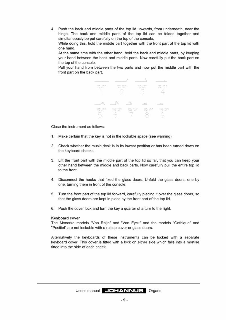
4. Push the back and middle parts of the top lid upwards, from underneath, near the hinge. The back and middle parts of the top lid can be folded together and simultaneously be put carefully on the top of the console. While doing this, hold the middle part together with the front part of the top lid with one hand. At the same time with the other hand, hold the back and middle parts, by keeping your hand between the back and middle parts. Now carefully put the back part on the top of the console. Pull your hand from between the two parts and now put the middle part with the front part on the back part.
Close the instrument as follows: 1. Make certain that the key is not in the lockable space (see warning). 2. Check whether the music desk is in its lowest position or has been turned down on
the keyboard cheeks. 3. Lift the front part with the middle part of the top lid so far, that you can keep your
other hand between the middle and back parts. Now carefully pull the entire top lid to the front.
4. Disconnect the hooks that fixed the glass doors. Unfold the glass doors, one by
one, turning them in front of the console. 5. Turn the front part of the top lid forward, carefully placing it over the glass doors, so
that the glass doors are kept in place by the front part of the top lid. 6. Push the cover lock and turn the key a quarter of a turn to the right. Keyboard cover The Monarke models "Van Rhijn" and "Van Eyck" and the models "Gothique" and "Positief" are not lockable with a rolltop cover or glass doors. Alternatively the keyboards of these instruments can be locked with a separate keyboard cover. This cover is fitted with a lock on either side which falls into a mortise fitted into the side of each cheek.

User's manual JOHANNUS Organs
- 10 -
Open the instrument as follows: 1. Insert the key in one of the locks. 2. Turn the key a quarter of a turn to the left; this brings the lock out. 3. Repeat this for the other lock. 4. Lift the keyboard cover from the keyboards. Close the instrument as follows: 1. Make certain that the key is not in the lockable space (see warning). 2. Put the keyboard cover on the keyboards. 3. Press one of the locks and turn the key a quarter of a turn to the right. Repeat this
for the other lock.
Stops The instrument may be fitted with one (or a combination) of the types of stops mentioned below. • Wooden drawstop • Lighted drawstop • Lighted rocker tab • Movable drawstop Wooden drawstops The Monarke models "Van Rhijn" and "Van Eyck" and the models "Gothique" and "Positief" are usually fitted with wooden drawstops. A stop can be turned on (activated) by pulling a stop. A stop can be turned off (deactivated) by pushing a stop. The position of a stop shows if a stop is activated or deactivated. An exception to this is formed by instruments featuring, besides wooden drawstops, a capture system and / or a general crescendo pedal. The position of a stop on instruments with a capture system shows if a stop is on or off, only when the HR-piston is activated. As soon as a fixed (preset) combination (one of the thumb pistons from PP to T inclusive) or a free (capture) combination (one of the pistons from 1 to 8 inclusive) is used, the registration is taken over by the capture system and the position of the stops no longer shows which stops are activated or deactivated. On instruments with a general crescendo pedal, hand registration is taken over by the general crescendo function, when the general crescendo pedal is used and the position of the stops no longer shows which stops are activated or deactivated.
User's manual JOHANNUS Organs
- 11 -
Lighted drawstops The Rembrandt models and the Monarke models "Vermeer" and "Van Gogh" are usually fitted with lighted drawstops. The Monarke models "Van Rhijn" and "Van Eyck" and the models "Gothique" and "Positief" may be fitted with lighted drawstops. After activating or deactivating a stop, a lighted drawstop springs back to the central position. For that reason each stop has a LED which lights up as soon as the stop is activated. This stop lighting also functions when using: • A fixed (preset) combination (one of the thumb pistons from PP to T inclusive) • A free (capture) combination (one of the pistons from 1 to 8 inclusive) • The general crescendo pedal Lighted rocker tabs The instruments of the Opus and Sweelinck series are fitted with lighted rocker tabs. On the Rembrandt models and the Monarke models "Vermeer" and "Van Gogh" the accessories may be designed as lighted rocker tabs. Alternatively instruments that are normally fitted with drawstops may be designed with lighted rocker tabs. After activating or deactivating a stop, a lighted rocker tab springs back to the central position. For that reason each stop has a LED which lights up as soon as the stop is activated. This stop lighting also functions when fixed (preset) combinations (one of the thumb pistons from PP to T inclusive) and free (capture) combinations (one of the pistons from 1 to 8 inclusive) and the general crescendo pedal are used. Moving drawstops Instruments that are normally designed with wooden or lighted drawstops may also be fitted with (automatically) moving drawstops. A stop can be turned on (activated) by pulling a stop. A stop can be turned off (deactivated) by pushing a stop. The position of a stop shows if a stop is activated or deactivated. When on an instrument with this type of stops and a capture system, a fixed (preset) combination (one of the thumb pistons from PP to T inclusive) or a free (capture) combination (one of the pistons from 1 to 8 inclusive) is used, all the stops belonging to this combination are automatically pushed out (activated). All the other stops are automatically "pulled in" (deactivated). On instruments with this type of stops and a general crescendo pedal, hand registration is taken over by the general crescendo function when the general crescendo pedal is used and the position of the stops no longer shows which stops are activated or deactivated.
User's manual JOHANNUS Organs
- 12 -
Set up Connecting the organ
Pay close attention to the following points when you connect your instrument: 1. Check whether the mains voltage, as indicated on the serial number plate, matches
the voltage of the mains to which the instrument is to be connected. The serial number plate is located left under the keyboards.
2. Connect the instrument to an earthed outlet. If this is not observed, there is a
possibility that certain functions of the instrument will not operate optimally. 3. The speaker boxes of instruments with a separate loudspeaker front should be
connected only with the appropriate loudspeaker cables. In many cases a separate loudspeaker front will be connected at installation by technicians of your JOHANNUS dealer or by technicians of JOHANNUS Orgelbouw b.v.. Be sure that, when you connect the front yourself, the instrument is switched off. Switch on the instrument only after all the loudspeaker cables have been connected. Loose loudspeaker cables may cause a short circuit which may result in breaking down of the power amplifiers of the instrument.
When another device is to be connected, see to it that both the organ and the device are switched off.
Switching on The instrument can be switched on with the mains switch. Location of the mains switch depends on your choice or the type of instrument: • Behind the hinged music desk (models "Van Rhijn" (Monarke) and "Gothique"). • Behind the pedalboard light cover (models "Van Eyck" (Monarke) and "Positief"). • Behind the hinged cover between keyboards and music desk. • Right next to the keyboards (Opus and Sweelinck) • Right next to the keyboards, under or next to one of the stop groups (Rembrandt and
the Monarke models "Vermeer" and "Van Gogh"). After switching on, it will take a few seconds before all the controls of the instrument are working. The various electronic circuits need this time to attain the correct settings (intializing). If a MIDI device is connected to a MIDI output of your instrument, the MIDI device should be switched on before the organ. This is ensure that the connected MIDI device is ready to receive the initial settings transmitted by the organ after switching on. The mains switch on your instrument may be designed as a push button with an pilot lamp or as a key switch. When the mains switch on your instrument is designed as a push button, the instrument can be switched on by pressing the mains switch. The pilot lamp in this type of mains pswitch shows whether the instrument is switched on or off.
User's manual JOHANNUS Organs
- 13 -
When the mains switch on your instrument is designed as a key switch, the instrument can be switched on by turning the key switch a quarter of a turn to the right. The position of the key switch shows whether the instrument is switched on or off. Note: On instruments with a key switch the mains switch is of the same type as the
memory lock. Both locks do come with different keys (two different key numbers). The memory lock is indicated by the nameplate "MEMORY LOCK". Make certain that you do not mistake the two switches.
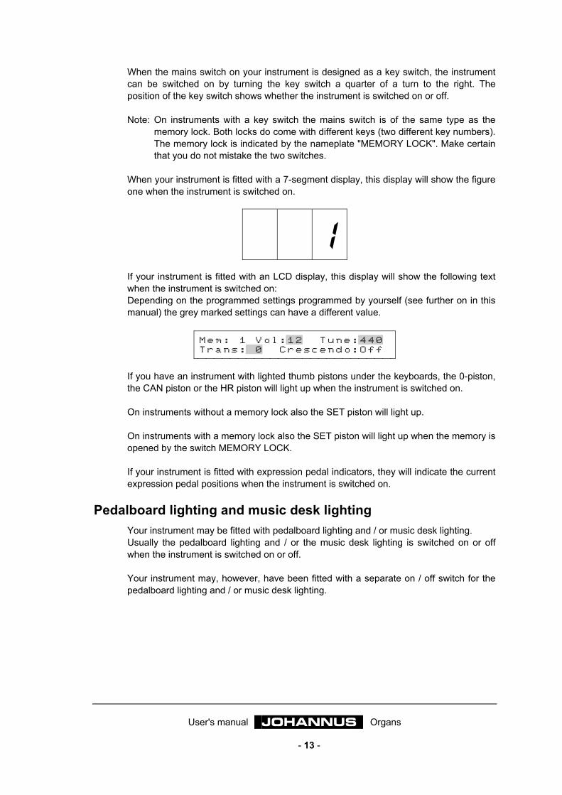
When your instrument is fitted with a 7-segment display, this display will show the figure one when the instrument is switched on.
1
If your instrument is fitted with an LCD display, this display will show the following text when the instrument is switched on: Depending on the programmed settings programmed by yourself (see further on in this manual) the grey marked settings can have a different value.
M e m : 1 V o l : 1 2 T u n e : 4 4 0 T r a n s : 0 C r e s c e n d o : O f f
If you have an instrument with lighted thumb pistons under the keyboards, the 0-piston, the CAN piston or the HR piston will light up when the instrument is switched on. On instruments without a memory lock also the SET piston will light up. On instruments with a memory lock also the SET piston will light up when the memory is opened by the switch MEMORY LOCK. If your instrument is fitted with expression pedal indicators, they will indicate the current expression pedal positions when the instrument is switched on.
Pedalboard lighting and music desk lighting Your instrument may be fitted with pedalboard lighting and / or music desk lighting. Usually the pedalboard lighting and / or the music desk lighting is switched on or off when the instrument is switched on or off. Your instrument may, however, have been fitted with a separate on / off switch for the pedalboard lighting and / or music desk lighting.
User's manual JOHANNUS Organs
- 14 -
The console in detail Standards
When building your instrument the existing, accepted standards in organ building are taken into account, wherever possible. The two most important standards are: 1. The BDO standard.
BDO stands for Bund Deutscher Orgelbaumeister. Instruments for the European continent are usually built according to this standard.
2. The AGO standard.
AGO stands for American Guild of Organists. Instruments for the Anglo-Saxon countries and the USA are usually built according to this AGO standard.
The most striking characteristic of AGO instruments is the design of the pedalboard. In contrast to the BDO instruments, AGO instruments do not know a straight or concave pedalboard but have always a concave pedalboard whose keys fan out to the front (radial). Another striking difference between BDO and AGO instruments is the order of stops.
Order of stops In making the order of stops, a number of factors have to be taken into account: • The organ building standards • The available space on the stop jambs • The symmetry between the left and the right stop jambs. • The position of the accessories • Determining the position of the stop groups belonging to a keyboard (division) • Determining the order of stops per division, the footage of a stop and the family to
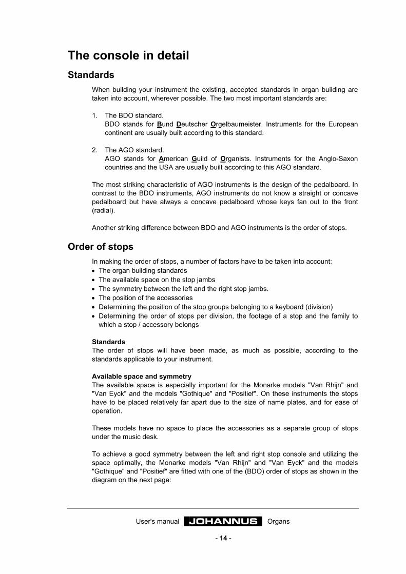
which a stop / accessory belongs Standards The order of stops will have been made, as much as possible, according to the standards applicable to your instrument. Available space and symmetry The available space is especially important for the Monarke models "Van Rhijn" and "Van Eyck" and the models "Gothique" and "Positief". On these instruments the stops have to be placed relatively far apart due to the size of name plates, and for ease of operation. These models have no space to place the accessories as a separate group of stops under the music desk. To achieve a good symmetry between the left and right stop console and utilizing the space optimally, the Monarke models "Van Rhijn" and "Van Eyck" and the models "Gothique" and "Positief" are fitted with one of the (BDO) order of stops as shown in the diagram on the next page:

User's manual JOHANNUS Organs
- 15 -
great +
access.
swell +
access.great swell
½ pedal
½ pedal
or
pedal
access.
On AGO instruments, the stops of the Swell are located on the left of the keyboards and the stops of the Great on the right.
swell +
access.
great +
access.swell great
½ pedal
½ pedal
or
pedal
access.
If the number of stops left and right is not the same, the two stop jambs can be made symmetric by adding one or several non-speaking stops (tacet stops). Possibly your instrument can be extended later by replacing these stops with speaking stops. The Rembrandt models and the Monarke models "Vermeer" and "Van Gogh" know great variation in the order of stops. Below some examples.
accessories
pedal great
swell
no stops
pedal great
access. swell
accessories
pedal great
swell choir
User's manual JOHANNUS Organs
- 16 -
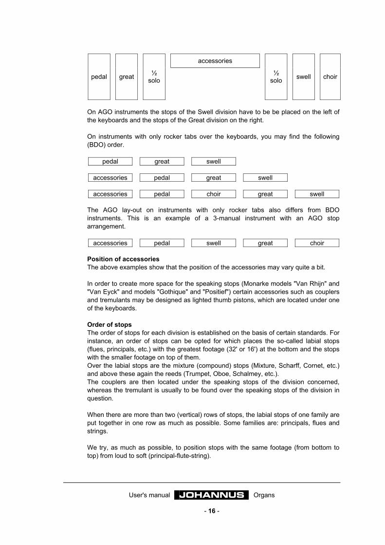
accessories
pedal great ½ solo
½ solo swell choir
On AGO instruments the stops of the Swell division have to be be placed on the left of the keyboards and the stops of the Great division on the right. On instruments with only rocker tabs over the keyboards, you may find the following (BDO) order.
pedal great swell
accessories pedal great swell
accessories pedal choir great swell The AGO lay-out on instruments with only rocker tabs also differs from BDO instruments. This is an example of a 3-manual instrument with an AGO stop arrangement.
accessories pedal swell great choir Position of accessories The above examples show that the position of the accessories may vary quite a bit. In order to create more space for the speaking stops (Monarke models "Van Rhijn" and "Van Eyck" and models "Gothique" and "Positief") certain accessories such as couplers and tremulants may be designed as lighted thumb pistons, which are located under one of the keyboards. Order of stops The order of stops for each division is established on the basis of certain standards. For instance, an order of stops can be opted for which places the so-called labial stops (flues, principals, etc.) with the greatest footage (32' or 16') at the bottom and the stops with the smaller footage on top of them. Over the labial stops are the mixture (compound) stops (Mixture, Scharff, Cornet, etc.) and above these again the reeds (Trumpet, Oboe, Schalmey, etc.). The couplers are then located under the speaking stops of the division concerned, whereas the tremulant is usually to be found over the speaking stops of the division in question. When there are more than two (vertical) rows of stops, the labial stops of one family are put together in one row as much as possible. Some families are: principals, flues and strings. We try, as much as possible, to position stops with the same footage (from bottom to top) from loud to soft (principal-flute-string).
User's manual JOHANNUS Organs
- 17 -
It is not always possible to realize an order of stops which, often also within a limited size of stop consoles, meets all the standards described above. However, we work towards applying the standards as much as possible.
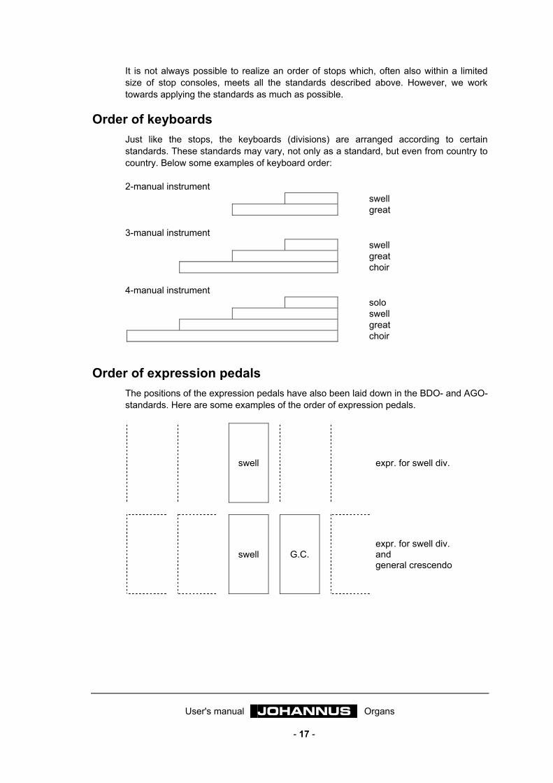
Order of keyboards
Just like the stops, the keyboards (divisions) are arranged according to certain standards. These standards may vary, not only as a standard, but even from country to country. Below some examples of keyboard order: 2-manual instrument
swell great
3-manual instrument
swell great choir
4-manual instrument
solo swell great choir
Order of expression pedals The positions of the expression pedals have also been laid down in the BDO- and AGO-standards. Here are some examples of the order of expression pedals.
swell expr. for swell div.
swell G.C. expr. for swell div. and general crescendo

User's manual JOHANNUS Organs
- 18 -
great
+ pedal
swell
+ choir
G.C.
expr. for great+pedal div expr. ped. for sw.+ch. div and general crescendo
great
+ pedal
swell G.C.
expr. for great+pedal div expr. for swell div. and general crescendo
choir great
+ pedal
swell G.C.
expr. for choir div. expr. for great+pedal div expr. for swell div. and general crescendo
choir great
+ pedal
swell solo G.C.
expr. for choir div. expr. for great+pedal div expr. for swell div. expr. for solo div. and general crescendo
The horizontal position of the expression pedals may also vary from type to type (of instrument). For the sake of symmetry, on instruments with panels left and right of the expression pedals, the expression pedals are mostly placed exactly in the centre, whereas according to BDO and AGO standards the expression pedals are not placed in the centre.
Thumb pistons Depending on the design, you may come across a number of (lighted) thumb pistons under the keyboards, or under, behind or above the music desk. The lighted thumb pistons are finished as switches which spring back to the central position after switching on or off. In each thumb piston a LED has been fitted that comes on as soon as it is activated. Now follows (in alphabetical order) a description of the thumb pistons that may occur on your instrument. Further on in this manual the function of a thumb piston may, where necessary, be dealt with more extensively.
User's manual JOHANNUS Organs
- 19 -
0-piston The 0-piston has a double function. You may have selected a fixed (preset) combination or manually switched on a stop, but this is not what you meant. Pressing the 0-piston briefly will undo the latter change. Example You are playing with the registration FLUTE 8', FLUTE 4' and FLUTE 2'. After some time you add PRINCIPAL 8' and PRINCIPAL 4'. Obviously it takes some time (perhaps a very short time) to switch on PRINCIPAL 8' and PRINCIPAL 4'. Pressing the 0-piston briefly, will cause PRINCIPAL 4' to be switched off (undo latter change). So PRINCIPAL 8' is not switched off as well (from the organist's point of view this would namely be part of the preceding registration). The instrument considers, as it were, the registration FLUTE 8', FLUTE 4', FLUTE 2', PRINCIPAL 8' the preceding choice, whereas the organist sees the registration FLUTE 8', FLUTE 4', FLUTE 2' as the previous choice. Pressing the 0-piston longer causes - with a few exceptions - all the activated stops to be switched off in one go. Exceptions are the couplers and the tremulants if the FA piston is pressed, and the stops Chorus and Intonation 2. N.B. The double function of the 0-piston may be designed as two separate pistons. With the 0-piston all the switched on stops may be switched off (save the
exceptions mentioned above) and with an extra piston (REC. = recall) the last change can be undone.
This piston may be called CAN. (= cancel) instead of 0-piston. 1 - 8 Pistons with which a personal registration is stored into the capture memory by giving them a number (from 1 to 8 inclusive) within a memory group. These pistons are needed again to recall the registrations stored into the capture memory. An instrument may have one or several groups of pistons from 1 to 8 inclusive. If an instrument has several groups of pistons from 1 to 8 inclusive you have free (capture) combinations at your disposal which may be programmed for the entire instrument (generals), but also for each division separately (separates). See also at "Using the capture system". – and + Pistons with which (if present on your instrument): • To select a memory group (Memory from 1 to 8 inclusive) of the capture system.
See also at "Using the capture system". • To select a programmable general crescendo step.
See also at "Using the general crescendo". • To set Volume, Tune and Transposer.
See also the description of "General volume", "Fine tuning" and "Transposer". • To program MIDI-stops.
See also "Programming MIDI-stops". When you hold the – or the + piston, it continues counting down or up automatically until the piston is released.

User's manual JOHANNUS Organs
- 20 -
ANC. OFF If your instrument (by means of MIDI) consists of a combination of a number of pipe organ voices and a number of electronically generated voices (a so-called hybrid instrument) the piston ANC. OFF (Ancillary Off) may occur on your instrument mostly in combination with a piston PIPE ON. Pressing this piston switches off the electronic voices of your hybrid organ in one go. CAN. = Cancel The piston CAN. may be found on instruments where the double function of the 0-piston has been replaced by two pistons (CAN. or 0-piston and REC. piston), each with a single function. With the CAN. piston (or the 0-piston) all the stops can be switched off (save the couplers and the tremulants, with the FA function switched on, and the accessories CHORUS and INTONATION 2) whereas the last change can be undone with the REC. piston (REC. = recall). CF = Cantus Firmus A thumb piston which switches the coupler Cantus Firmus on or off. See also at "Cantus Firmus". CH = Chorus A thumb piston which switches the chorus effect on or off. See also at "Chorus". Couplers Coupler stops may be designed as drawstops or rocker tabs. For lack of space on the stop panels they may have been fitted as pistons under the keyboards. See also at "Couplers". Coupler stops can be designed as normal stops, as well as thumb pistons (and as toe pistons). In this way a coupler can be operated in two or three ways: with a stop, with a thumb piston under the keyboards and / or with a toe piston. If a coupler stop has been designed twofold or threefold, the coupler stop can be switched on or off with each of the two or three controls. In other words, if a coupler is switched off, the coupler concerned can be switched on with each of the two or three controls, and vice versa. CR = General Crescendo A thumb piston which switches the function of the general crescendo on or off. See also at "Using the general crescendo". FA = Fix Accessories When the couplers and the tremulants are used in the fixed (preset) combinations or free (capture) combinations or when the 0-piston or CAN. piston is used, they will change with it. This can be prevented by pressing the FA piston. As long as this thumb piston is on, the couplers and the tremulants can only be switched on or off manually.

User's manual JOHANNUS Organs
- 21 -
HR = Hand registration The HR piston is found only on instruments with wooden drawstops (Monarke models "Van Rhijn" and "Van Eyck" and models "Gothique" and "Positief"). By pressing this thumb piston, you change from a fixed (preset) or a free (capture) combination to hand registration. As soon as the HR piston is pressed, only the manually switched on (drawn) stops will sound. As long as the HR piston is on, stops can be switched on or off manually. When you have selected a fixed (preset) or a free (capture) combination and you switch a stop manually on or off, the selected fixed (preset) or free (capture) combination plus hand registration (HR+ function) will be activated at once. This will be illustrated with a couple of examples. Example 1 1. No stop is on. 2. The fixed combination PP (with e.g. the stops SUBBASS 16' pedal, ROHRFLUTE 8'
great and STOPPED FLUTE 8' swell) has been selected. 3. The HR-knop is not on. When you play the swell division, only the stop STOPPED FLUTE 8' will sound. Manual switching on of e.g. FLUTE 4' of the swell division will make both the stop STOPPED FLUTE 8' (PP) and the stop FLUTE 4' (HR) sound. Both thumb pistons PP and HR (and the 0-piston) will be lit. Example 2 1. The stop Octave 4' of the swell has been drawn. All other stops are off. 2. The fixed combination PP (with e.g. the stops SUBBASS 16' pedal, ROHRFLUTE
8' great and STOPPED FLUTE 8' swell) is selected. 3. The HR piston is not on. When you play the swell division, only the stop STOPPED FLUTE 8' will sound. Manual switching on of e.g. the OCTAVE 2' of the swell will make both the stop STOPPED FLUTE 8' (PP) and the stops OCTAVE 4' and OCTAVE 2' (HR) sound. Both thumb pistons PP and HR (and the 0-piston) will be lit. Example 3 1. The stops OCTAVE 4' of the swell and the coupler SWELL-GREAT are on. All other
stops are off. 2. The fixed combination PP (with e.g. the stops SUBBASS 16' pedal, ROHRFLUTE 8'
great and STOPPED FLUTE 8' swell) is selected. 3. The HR piston is not on. When you now play the great division, only the stop ROHRFLUTE 8' will sound. Because the coupler stop is now switched on, manual switching on e.g. the OCTAVE 2' of the swell, will make both the stop ROHRFLUTE 8' (PP) and the stops OCTAVE 4' and OCTAVE 2' (HR) sound. Both thumb pistons PP and HR (and the 0-piston) will be lit. Stops switched on by selecting a fixed (preset) combination or a free (capture) combination cannot be manually switched off. In the above examples manual switching off of the STOPPED FLUTE 8' will have no effect, because the fixed combination thumb piston PP retains it. In other words: the fixed (preset) and free (capture) combinations take precedence over hand registration.

User's manual JOHANNUS Organs
- 22 -
INT2 = Intonation 2 Thumb piston for selecting another intonation. See also at "Intonation 2" and at "Choice of temperament". KT = Keyboard transfer By pressing this thumb piston, two (always the same) keyboards can be interchanged. When the keyboard transfer is activated, the functions belonging to a certain division remain with that division. Using keyboard transfer may simplify playing certain music. Example: Usually the order of keyboards on a 3-manual instrument (from bottom to top) is choir-great-swell. French organs, however, often have a different order of keyboards (great-choir-swell). The music notation of French composers has taken this (French) keyboard order into account. With the KT piston the great and choir keyboards can be simply interchanged. M1 and M2 Thumb pistons with which a selected registration can be stored into a memory group M1 (Opus 1) or M2 (Opus 5). On the Opus 1 thumb piston M1 switches from the fixed (preset) combinations to the free (capture) combinations. On the Opus 5 thumb piston M2 switches from capture memory group 1 (M2 not activated) to capture memory group 2 (M2 activated).These thumb pistons are needed again to recall the registrations stored into the memory. See also at "Using the capture system". MB = Manual Bass Thumb piston for switching the coupler Manual Bass on or off. See also at "Couplers". MIDI’s The MIDI-stops (or switches) form a separate group of accessories. See for their use the chapters "Application of MIDI" and "Programming MIDI-stops". MT = Meantone Thumb piston for selecting the Meantone temperament. See also at "Meantone" and at "Choice of temperament". PGM = Programming General crescendo and MIDI-stops Thumb piston enabling the stop combinations of the general crescendo to be changed or the MIDI-stops (or switches) to be programmed. See also at "Using the general crescendo" and at "Programming MIDI-stops". PIPE ON If your instrument (by using MIDI) consists of a combination of a number of pipe organ voices and a number of electronically generated voices (a so-called hybrid instrument) the piston ANC. OFF (Ancillary Off) may occur on your instrument mostly in combination with a piston PIPE ON. Pressing this piston activates the pipe organ part of the combined instrument. Only after pressing the PIPE ON can the voices of the pipe organ part be switched on or off with the appropriate stops.

User's manual JOHANNUS Organs
- 23 -
PP - T = Pianissimo to Tutti inclusive The fixed (presets) combinations are groups of stops, set up according to fixed musical standards, starting from PP (pianissimo: very soft) to T (tutti: very loud) inclusive. In fact there is little difference between the fixed (preset) combinations and the free (capture) combinations. Both are programmable. The differences between the fixed (preset) and free (capture) combinations are: 1. Due to the indications on the pistons With the fixed combinations you are restricted
to programming certain registrations for the pistons. It is impossible to program the PP piston with many and or loud voices.
2. The fixed combinations have only one memory group, so that only one combination can be stored per piston. The free (capture) combinations (except on the Opus 1) have two, four, or more capture memory groups, which allows two, four or more combinations to be stored per piston.
3. With fixed combinations it is possible to reset the stop combinations set by the designer of the instrument.
The default stop combinations of each fixed combination can be changed and stored into the fixed combination memory. The default stop combinations - set by the designer of the instrument - can always be reset into the fixed combination memory. However, this is only possible for all the fixed combinations together. All the stop combinations set by the user will be lost in the process. See for resetting the default fixed stop combinations "Special functions thumb pistons". The fixed combinations memory has been protected in such a way that the stored registrations are not lost whenever the instrument is switched off or when the plug is pulled from the wall socket. A fixed combination is programmed as follows 1. Make sure the pistons CR and PGM are not pressed, if your instrument has a
programmable general crescendo pedal and / or programmable MIDI-stops. This is meant to prevent the stop combinations of the general crescendo or a programmed MIDI-stop from being changed by accident.
2. Open the fixed combination memory by turning the key switch MEMORY LOCK a
quarter of a turn to the right. The SET piston will come on as a sign that the capture memory is open.
3. Select the registration you want stored into the fixed combination memory. 4. Press SET, hold it and then select a fixed combination piston (e.g. MF) and press it
briefly. 5. First release the piston for the fixed combination (in this example MF) and only then
the SET piston.
User's manual JOHANNUS Organs
- 24 -
6. After programming one or more fixed combinations, close the fixed combination memory by turning the key switch MEMORY LOCK a quarter of a turn to the left (pulling the key from the switch). The LED in the SET piston will switch off indicating that the fixed combination memory is closed again.
7. If you wish you can write the freshly programmed fixed combination (e.g. MF) on
the composition for which you intend using this registration. The changed registration of the fixed combination piston MF is now stored. A fixed combination can be recalled by briefly pressing the required fixed combination piston. Recalling a personal registration does not require opening the fixed combination memory with the key switch MEMORY LOCK. The working of the T piston is twofold. When you are playing with a registration of your own or with a fixed combination (from PP to T inclusive), you will get the full organ by pressing the T piston; the normal effect of this thumb piston. However, by pressing this thumb piston again, you will recover the preceding registration. On instruments with lighted stops, pressing one of the preset pistons shows which stops are switched on. On instruments with moving drawstops, pressing one of the preset pistons shows which stops are switched on (by their position). It is also possible to manually switch stops on or off within a fixed combination. REC. = Recall (undo last change) The piston REC. may be found on instruments where the double function of the 0-piston has been replaced by two pistons (REC. piston and CAN. or 0-piston), each with a single function. With the REC. piston (REC. = recall) the latest change can be undone, whereas the CAN. piston (or the 0-piston) can switch off all the stops. Exceptions are the couplers and the tremulants if the FA function and the stops CHORUS and INTONATION 2 are switched on. RO = Reeds off On the far right of the fixed (preset) combinations is the thumb piston RO (Reeds Off). Pressing this thumb piston switches off all the reeds in one go. As long as the RO piston is pressed, no reeds can be switched on. SEQ (sequence) If your instrument has been fitted with an extensive capture system (a capture memory for the entire instrument and a capture memory for each separate division, your instrument may have one single SEQ piston (without further indication) instead of the two pistons SEQ– and SEQ+ (see below). Activation of the single SEQ piston gives all the capture pistons or toe pistons from 1 to 8 inclusive which are normally used for the pedal capture the function SEQ (see below), whereas all the capture pistons or toe pistons from 1 to 8 inclusive which are normally used for the entire instrument get the function SEQ (see below).

User's manual JOHANNUS Organs
- 25 -
SEQ– en SEQ+ (sequence) If your instrument has been fitted with a capture system, a number of registrations of your own choice can be stored into the memory of the capture system. These registrations can be recalled at any given moment. A capture system is always composed of a number of memory groups (1, 2, 4, 8, 16 or more) to be selected with the thumb pistons – and + or from M1 or M2. Each memory group has eight locations (pistons from 1 to 8 inclusive). A registration of your own choice can be stored at any place. So recalling a stored capture combination always has to be done by means of two pistons; one piston (–, +, M1 or M2) to select the correct memory group and one piston (from 1 to 8 inclusive) to select the correct memory location. By means of the sequence pistons the entire memory can be run through consecutively. With the SEQ– to lower memory locations and with the SEQ+ to a higher memory location. In this way a concert may be prepared by programming 128 registrations for the entire concert in succession into the capture memory. TIP: Using the SEQ– and SEQ+ functions, you will not program a different registration
at each memory location, but rather pay more attention to the registrations as they succeed one another in time during a concert. It is very well possible that exactly the same registration occurs in several memory locations, because the same registration may occur more than once during the concert. However, this will not be a problem considering the large number of memory locations.
The following diagram gives the sequence numbers of all (16x 8 = 128) the memory locations of a capture system with 16 memory groups and 8 memory locations per group.
mem
ory
grou
p 1
mem
ory
grou
p 2
mem
ory
grou
p 3
mem
ory
grou
p 4
mem
ory
grou
p 5
mem
ory
grou
p 6
mem
ory
grou
p 7
mem
ory
grou
p 8
mem
ory
grou
p 9
mem
ory
grou
p 10
mem
ory
grou
p 11
mem
ory
grou
p 12
mem
ory
grou
p 13
mem
ory
grou
p 14
mem
ory
grou
p 15
mem
ory
grou
p 16
memory location 1 1 9 17 25 33 41 49 57 65 734 81 89 97 105 113 121
memory location 2 2 10 18 26 34 42 50 58 66 74 82 90 98 106 114 122
memory location 3 3 11 19 27 35 43 51 59 67 75 83 91 99 107 115 123
memory location 4 4 12 20 28 36 44 52 60 68 76 84 92 100 108 116 124
memory location 5 5 13 21 29 37 45 53 61 69 77 85 93 101 109 117 125
memory location 6 6 14 22 30 38 46 54 62 70 78 86 94 102 110 118 126
memory location 7 7 15 23 31 39 47 55 63 71 79 87 95 103 111 119 127
memory location 8 8 16 24 32 40 48 56 64 72 80 88 96 104 112 120 128
User's manual JOHANNUS Organs
- 26 -
SET This is a thumb piston for programming: • Free (capture) combinations.
See also at "Using the capture system". • Fixed (preset) combinations.
See also at "Thumb pistons , PP to T inclusive". • Stop combinations of the general crescendo.
See also at "Using the general crescendo". • Volume, Tune and Transposer settings.
See also at the description of "General volume", "Fine tuning" and "Transposer". • MIDI-stops.
See also at "Programming MIDI-stops". S/S An instrument with three or more expression pedals may be fitted with a thumb piston S/S. On instruments with two expression pedals, it is still possible to operate two expression pedals at the same time with one foot by placing it on both expression pedals simultaneously. Instruments with more than two expression pedals do not allow this. With the S/S-piston all the expression pedals can be coupled to the expression pedal of the swell division. By pressing this thumb piston, the volume of all the divisions can be set simultaneously with one expression pedal, the swell division expression pedal. When the S/S function is switched on, each division at once adopts the volume set with the expression pedal of the swell. When the S/S function is switched off, the volume of each division returns to the one fitting the appropriate expression pedal. TRANS. = Transposer Thumb piston for setting and storing the transposer setting. See also at "Transposer". Tremulants When the tremulant stops have been fitted under the music desk (Rembrandt models and Monarke models "Vermeer" and "Van Gogh"), they have been designed as rocker tabs. When the tremulant stops are placed at the stop jambs of the concerned divisions, the same type of stops are used for speaking stops as well as the tremulant stops. If there is not enough space on the stop consoles or under the music desk (Monarke models "Van Rhijn" and "Van Eyck" and models "Gothique" and "Positief") the tremulant stops can also be located as thumb pistons under the keyboards. TUNE = Pitch Thumb piston for setting and storing the pitch setting. See also at "Fine tuning". VOL. = Volume Thumb piston for setting and storing the volume setting. See also at "General volume". WM = Werckmeister III Thumb piston for selecting the Werckmeister III temperament. See also at "Werckmeister III" and at "Choice of temperament".

User's manual JOHANNUS Organs
- 27 -
Couplers One or several couplers are standard on instruments with 2 of more manuals. Unless otherwise stated, all the couplers are full, that is to say, that all the keys which are pressed are coupled. The coupler stops may be designed as stops, and as thumb pistons and as toe pistons. Hence a coupler can be operated in two or three ways: with a stop, with a thumb piston under the keyboards and / or with a toe piston. If a coupler stop has been designed twofold or threefold, the coupler stop can always be switched on or off with each of the two or three controls. In other words, if a coupler is switched off, the coupler in question can be switched on again with each of the two or three controls and vice versa.
Manual couplers With a manual coupler, a manual can be coupled to another manual. If, e.g. the coupler SWELL - GREAT is switched on, the coupled key of the swell will also sound, as soon as a key of the great is pressed. In this way the stops of the great can be supplemented with the stops of the swell. Your instrument may be designed with the following manual couplers: • SWELL - GREAT (instrument with 2 or more manuals) • CHOIR - GREAT (instrument with 3 or more manuals) • SWELL - CHOIR (instrument with 3 or more manuals) • SOLO - GREAT (instrument with 4 manuals) • SOLO - SWELL (instrument with 4 manuals) • SOLO - CHOIR (instrument with 4 manuals) Instruments with more than 4 manuals may have a larger number of manual couplers.
• Pedal couplers With a pedal coupler a manual can be coupled to the pedal. If, e.g. the coupler GREAT-PEDAL is switched on, the coupled key of the great will also sound, as soon as a pedal key is pressed. In this way the stops of the pedal can be supplemented with the stops of the great. Your instrument may be designed with the following pedal couplers: • GREAT - PEDAL (instrument with 2 or more manuals) • SWELL - PEDAL (instrument with 2 or more manuals) • CHOIR - PEDAL (instrument with 3 or more manuals) • SOLO - PEDAL (instrument with 4 or more manuals) Instruments with more than 4 manuals may have a larger number of pedal couplers. Sub- and super couplers Apart from the usual manual and pedal couplers, sub and super couplers may be added to your instrument. When one manual is coupled to another manual (pedal), the usual couplers will make the stops that are coupled to the other manual (pedal) sound at their own, true footage pitch.

User's manual JOHANNUS Organs
- 28 -
When a sub coupler is switched on, the stops that are coupled to the other manual (pedal) will sound an octave lower. When a super coupler is switched on, the stops that are coupled to the other manual (pedal) will sound an octave higher. Apart from the sub and super couplers between the manuals, sub and super couplers functioning within the same manual (intramanual couplers) may be fitted. When an instrument has sub and super couplers besides the usual couplers, the difference between the various couplers will be marked with a footage indication. A normal coupler will be indicated as 8', a sub coupler as 16' and a super coupler as 4' e.g.: • SWELL - GREAT 4' (super coupler swell to great) • SWELL - GREAT 8' (normal coupler swell to great) • SWELL - GREAT 16' (sub coupler swell to great) • SWELL - SWELL 4' (super coupler for the swell) • SWELL - SWELL 16' (sub coupler for the swell) Cantus Firmus Switching on the stop (or the thumb piston) Cantus Firmus (CF), couples the swell to the great. This coupler is a so-called monophonic coupler. That means that only one key at a time is coupled from the swell to the great. When a chord is played on the great, the highest note of that chord is coupled from the swell to the great. In this way the effect of a solo stop is achieved. When the coupler "SWELL - GREAT" is used Cantus Firmus function has no effect. Manual Bass By switching on the stop (or the thumb piston) Manual Bass (MB), the pedal can be coupled to the great. This coupler is a so-called monophonic coupler. That means that one key at a time is coupled from the pedal to the great. When a chord is played on the great, the lowest note of that chord is coupled from the pedal to the great.
Tremulants Tremulants are meant to vibrate the sound of the organ to reduce the rigidity of the tone. Each division may have its own tremulant. Normally , the tremulants are designed as stops . If there is not enough space on the stop consoles or under the music desk (Monarke models "Van Rhijn" and "Van Eyck" and models "Gothique" and "Positief") tremulant stops may also be thumb pistons placed under the keyboards. When the couplers and / or the stop Cantus Firmus (CF) are used, the tremulants of the concerning divisions are coupled as well. When one of the divisions of your instrument has been supplemented with the stop "TIBIA ORGAN" or "GOSPEL ORGAN" (module voice), this stop has its own particular tremulant stop "Tremolo".
User's manual JOHANNUS Organs
- 29 -
Other accessories Your instrument may be fitted with one or more of the following accessories. Chorus To avoid the instrument sounding too sterile, the organ has been designed in such a way that various stops are slightly detuned in relation to each other. This gives the instrument a "broader", more "lively" character. When your instrument has the accessory CHORUS (CH), this effect can be strengthened by switching on this accessory. Intonation 2 Intonation determines the timbre of the instrument. In pipe organ building, tuning (voicing) is a very important aspect of the trade. Every pipe organ is adjusted, stop by stop, to the area where the instrument is installed. The accessory INTONATION 2 occurs on instruments which are fitted with two intonations, one romantic, one baroque. If your instrument has two intonations, you can switch between one intonation and the other with the accessory INTONATION 2 (INT2). In general, a romantic instrument sounds somewhat "rounder", whereas the timbre of an instrument with a baroque intonation is slightly brighter. Meantone Normally your instrument has Equal temperament (normal temperament). By switching on the accessory Meantone (MT), Meantone temperament is selected. As soon as this temperament is switched on, the Werckmeister III temperament will automatically be switched off, if it is on. See also at "Choice of temperament". MIDI-stops The MIDI-stops (or switches) form a separate group of accessories. See for its usage at "Application of MIDI" and "Programming MIDI-stops". Unisono off On an instrument with sub and / or super couplers, the accessory UNISONO OFF may be found. With this stop the real footage of a stop is switched off, so that only the footage of the sub or super coupler is heard. An example: When the sub coupler SWELL - SWELL 16' and the super coupler SWELL - SWELL 4' of the swell is switched on, and the stop UNISONO OFF is not on, pressing a key will produce three notes. The original note, a note sounding an octave lower and a note sounding an octave higher. When the stop UNISONO OFF is on, pressing a key will produce only two notes. The note sounding an octave lower and the note sounding an octave higher. The original note has been switched off with the stop UNISONO OFF.
User's manual JOHANNUS Organs
- 30 -
Werckmeister III Normally your instrument has Equal temperament (normal temperament). By switching on the accessory WERCKMEISTER III (WM), Werckmeister III temperament is selected. As soon as this temperament is switched on, the Meantone temperament will automatically be switched off, if it is on. See also at "Choice of temperament". Wind pressure stabilization Stop or thumb piston for switching on or off the wind pressure stabilization. The wind supply of pipe organs is never ideal. Ideally the wind pressure in the wind chest would always be constant. Whenever a valve under a pipe is opened (on a pipe organ), the wind pressure will go down a little for a moment, because the wind chest develops a "leak", so to speak. Depending on the number of valves that is opened at one time (number of stops and keys) and the size of the pipes, the variation in wind pressure may be larger or smaller. These variations in wind pressure influence the pitch of the pipes sounding at that moment. These changes in pitch may liven up the tone of your instrument, if they are not too great. Very large changes in pitch, however, will be found annoying. Instruments with this deficiency are known as "prone to windsag". With the accessory wind pressure stabilization (WS) this effect can be switched on or off. Switching off the accessory, deactivates the wind pressure stabilizer. The effect of the wind pressure variations is then more or less audible, depending on the number of stops, the kind of stops and the number of keys. Switching on the accessory, activates the wind pressure stabilizer. This means that no wind pressure variations will occur.
Toe pistons Besides having thumb pistons under the keyboards, your instrument may be fitted with a number of toe pistons. Now follows a description of the usual functions of toe pistons. COUPLER-pistons With these toe pistons the couplers can be operated. When a coupler is switched off, it can be switched on again with the accompanying toe piston and vice versa. See at "Couplers". TUTTI-piston This toe piston has the same function as the thumb piston T(utti) of the fixed (preset) combinations. See at "PP to T = Pianissimo to Tutti inclusive". CAPTURE-pistons These toe pistons have the same functions as the thumb pistons from 1 to 8 inclusive (generals) of the capture system. Mostly these are the thumb pistons from 1 to 8 inclusive (generals) of the generals. An instrument with separates may have the double function of the thumb pistons from 1 to 8 inclusive of the pedal and/or swell. See at "1 - 8" and "Using the capture system" .

User's manual JOHANNUS Organs
- 31 -
SEQ– and SEQ+-pistons These toe pistons have the same function as the thumb pistons SEQ– and SEQ+ under the keyboards. See at "SEQ– and SEQ+". (32')-stop-pistons With the 32'-stop toe pistons, 32'-stops can be operated. When a 32'-stop is switched off, it can be switched on again with the appropriate toe piston and vice versa. Besides 32'-stops, other, special stops can be assigned to toe pistons, such as, e.g. a high pressure stop like the Tuba, a reed with a special character, or a Zimbelstern.
Displays Your instrument may be fitted with one of the following displays. 7-segment display A 7-segment display is a 3-digit display. Each of the three digits consists of 7 segments (hence: 7-segment display).
8. 8. 8. The display has various functions: • When the CR piston is not pressed, the display will show the selected memory group
of the capture system. In reflecting the memory group of the capture system only those numbers will light up which are necessary to reflect the selected memory group of the capture system. See also at "Using the capture system".
1 2
• When the general crescendo pedal is switched on with the CR piston, the display will show to which step the general crescendo pedal is pressed down (exept the Opus series). Except general crescendo step 0, all numbers will light up in reflecting a general crescendo step. See also at "Using the general crescendo".
0 1 2

User's manual JOHANNUS Organs
- 32 -
For general crescendo step 0 (or all stops of the general crescendo off) the display will show no number (except the Opus series) See also at "Using the general crescendo".
• When the thumb pistons CR and PGM are pressed, the display will show which step of the general crescendo has been selected. In reflecting the programmable general crescendo step all the numbers will light up just like when the current general crescendo step is shown, (except the Opus series). See also at "Using the general crescendo".
• When only the PGM function is activated and a MIDI-stop is switched on, the display will show which channel/module voice number (patch number) is assigned to the MIDI- stop concerned. When the PGM function is used all the numbers will light up.
0 1 2
• When only the PGM function is activated and no MIDI-stop is switched on, the display will show no number. See also at "Programming MIDI-stops".
LCD-display This type of display (LCD stands for Liquid Crystal Display) will show various settings: • Selected capture memory group .
See also at "Using the capture system".
M e m : 1 V o l : 1 2 T u n e : 4 4 0 T r a n s : 0 C r e s c e n d o : O f f
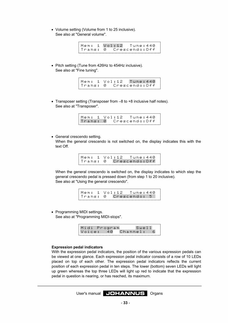
User's manual JOHANNUS Organs
- 33 -
• Volume setting (Volume from 1 to 25 inclusive). See also at "General volume".
M e m : 1 V o l : 1 2 T u n e : 4 4 0 T r a n s : 0 C r e s c e n d o : O f f
• Pitch setting (Tune from 426Hz to 454Hz inclusive). See also at "Fine tuning".
M e m : 1 V o l : 1 2 T u n e : 4 4 0 T r a n s : 0 C r e s c e n d o : O f f
• Transposer setting (Transposer from –8 to +8 inclusive half notes). See also at "Transposer".
M e m : 1 V o l : 1 2 T u n e : 4 4 0 T r a n s : 0 C r e s c e n d o : O f f
• General crescendo setting. When the general crescendo is not switched on, the display indicates this with the text Off.
M e m : 1 V o l : 1 2 T u n e : 4 4 0 T r a n s : 0 C r e s c e n d o : O f f
When the general crescendo is switched on, the display indicates to which step the general crescendo pedal is pressed down (from step 1 to 20 inclusive). See also at "Using the general crescendo".
M e m : 1 V o l : 1 2 T u n e : 4 4 0 T r a n s : 0 C r e s c e n d o : 5
• Programming MIDI settings. See also at "Programming MIDI-stops".
M i d i P r o g r a m S w e l l V o i c e : 4 0 C h a n n e l : 6
Expression pedal indicators With the expression pedal indicators, the position of the various expression pedals can be viewed at one glance. Each expression pedal indicator consists of a row of 10 LEDs placed on top of each other. The expression pedal indicators reflects the current position of each expression pedal in ten steps. The lower (bottom) seven LEDs will light up green whereas the top three LEDs will light up red to indicate that the expression pedal in question is nearing, or has reached, its maximum.
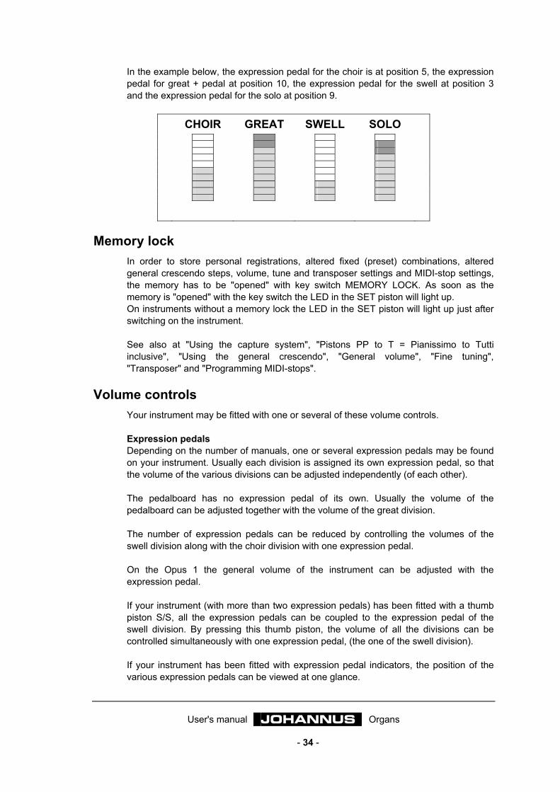
User's manual JOHANNUS Organs
- 34 -
In the example below, the expression pedal for the choir is at position 5, the expression pedal for great + pedal at position 10, the expression pedal for the swell at position 3 and the expression pedal for the solo at position 9.
CHOIR GREAT SWELL SOLO
Memory lock
In order to store personal registrations, altered fixed (preset) combinations, altered general crescendo steps, volume, tune and transposer settings and MIDI-stop settings, the memory has to be "opened" with key switch MEMORY LOCK. As soon as the memory is "opened" with the key switch the LED in the SET piston will light up. On instruments without a memory lock the LED in the SET piston will light up just after switching on the instrument. See also at "Using the capture system", "Pistons PP to T = Pianissimo to Tutti inclusive", "Using the general crescendo", "General volume", "Fine tuning", "Transposer" and "Programming MIDI-stops".
Volume controls Your instrument may be fitted with one or several of these volume controls. Expression pedals Depending on the number of manuals, one or several expression pedals may be found on your instrument. Usually each division is assigned its own expression pedal, so that the volume of the various divisions can be adjusted independently (of each other). The pedalboard has no expression pedal of its own. Usually the volume of the pedalboard can be adjusted together with the volume of the great division. The number of expression pedals can be reduced by controlling the volumes of the swell division along with the choir division with one expression pedal. On the Opus 1 the general volume of the instrument can be adjusted with the expression pedal. If your instrument (with more than two expression pedals) has been fitted with a thumb piston S/S, all the expression pedals can be coupled to the expression pedal of the swell division. By pressing this thumb piston, the volume of all the divisions can be controlled simultaneously with one expression pedal, (the one of the swell division). If your instrument has been fitted with expression pedal indicators, the position of the various expression pedals can be viewed at one glance.
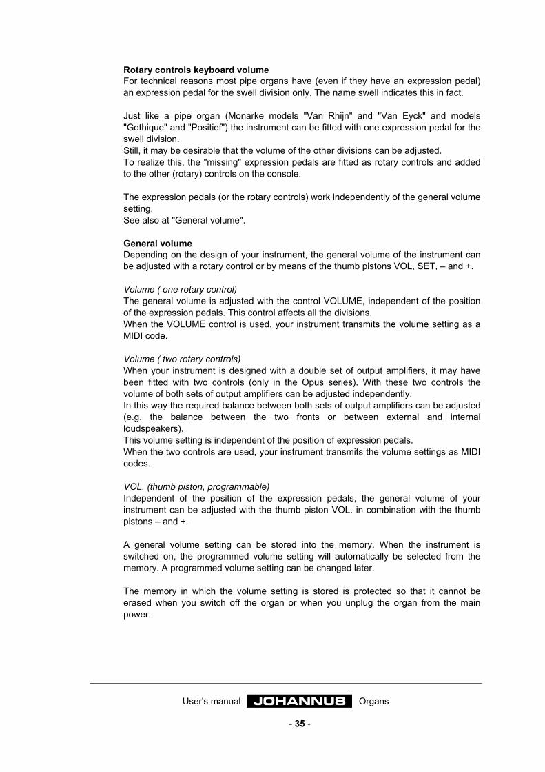
User's manual JOHANNUS Organs
- 35 -
Rotary controls keyboard volume For technical reasons most pipe organs have (even if they have an expression pedal) an expression pedal for the swell division only. The name swell indicates this in fact. Just like a pipe organ (Monarke models "Van Rhijn" and "Van Eyck" and models "Gothique" and "Positief") the instrument can be fitted with one expression pedal for the swell division. Still, it may be desirable that the volume of the other divisions can be adjusted. To realize this, the "missing" expression pedals are fitted as rotary controls and added to the other (rotary) controls on the console. The expression pedals (or the rotary controls) work independently of the general volume setting. See also at "General volume". General volume Depending on the design of your instrument, the general volume of the instrument can be adjusted with a rotary control or by means of the thumb pistons VOL, SET, – and +. Volume ( one rotary control) The general volume is adjusted with the control VOLUME, independent of the position of the expression pedals. This control affects all the divisions. When the VOLUME control is used, your instrument transmits the volume setting as a MIDI code. Volume ( two rotary controls) When your instrument is designed with a double set of output amplifiers, it may have been fitted with two controls (only in the Opus series). With these two controls the volume of both sets of output amplifiers can be adjusted independently. In this way the required balance between both sets of output amplifiers can be adjusted (e.g. the balance between the two fronts or between external and internal loudspeakers). This volume setting is independent of the position of expression pedals. When the two controls are used, your instrument transmits the volume settings as MIDI codes. VOL. (thumb piston, programmable) Independent of the position of the expression pedals, the general volume of your instrument can be adjusted with the thumb piston VOL. in combination with the thumb pistons – and +. A general volume setting can be stored into the memory. When the instrument is switched on, the programmed volume setting will automatically be selected from the memory. A programmed volume setting can be changed later. The memory in which the volume setting is stored is protected so that it cannot be erased when you switch off the organ or when you unplug the organ from the main power.
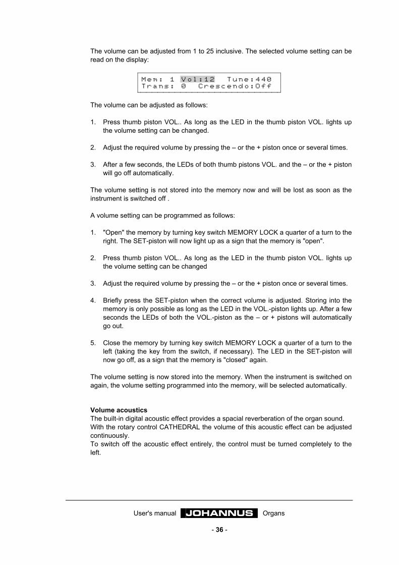
User's manual JOHANNUS Organs
- 36 -
The volume can be adjusted from 1 to 25 inclusive. The selected volume setting can be read on the display:
M e m : 1 V o l : 1 2 T u n e : 4 4 0 T r a n s : 0 C r e s c e n d o : O f f
The volume can be adjusted as follows: 1. Press thumb piston VOL.. As long as the LED in the thumb piston VOL. lights up
the volume setting can be changed. 2. Adjust the required volume by pressing the – or the + piston once or several times. 3. After a few seconds, the LEDs of both thumb pistons VOL. and the – or the + piston
will go off automatically. The volume setting is not stored into the memory now and will be lost as soon as the instrument is switched off . A volume setting can be programmed as follows: 1. "Open" the memory by turning key switch MEMORY LOCK a quarter of a turn to the
right. The SET-piston will now light up as a sign that the memory is "open". 2. Press thumb piston VOL.. As long as the LED in the thumb piston VOL. lights up
the volume setting can be changed 3. Adjust the required volume by pressing the – or the + piston once or several times. 4. Briefly press the SET-piston when the correct volume is adjusted. Storing into the
memory is only possible as long as the LED in the VOL.-piston lights up. After a few seconds the LEDs of both the VOL.-piston as the – or + pistons will automatically go out.
5. Close the memory by turning key switch MEMORY LOCK a quarter of a turn to the
left (taking the key from the switch, if necessary). The LED in the SET-piston will now go off, as a sign that the memory is "closed" again.
The volume setting is now stored into the memory. When the instrument is switched on again, the volume setting programmed into the memory, will be selected automatically.
Volume acoustics The built-in digital acoustic effect provides a spacial reverberation of the organ sound. With the rotary control CATHEDRAL the volume of this acoustic effect can be adjusted continuously. To switch off the acoustic effect entirely, the control must be turned completely to the left.
User's manual JOHANNUS Organs
- 37 -
Pitch settings The standard pitch of musical instruments is: A=440Hz. Depending on the type of instrument, the pitch of your instrument can be adjusted in one of the following ways: • A rotary control PITCH (fine tuning) in combination with a selector switch
TRANSPOSER. • The Thumb piston TUNE (fine tuning) in combination with the thumb piston TRANS.
(transposer). Fine tuning The fine tuning can be adjusted continuously with the rotary control PITCH or in steps of 1Hz by means of the thumb pistons TUNE, SET, – and + . PITCH (rotary control) With the rotary control PITCH, the pitch of your instrument can be adjusted continuously a quarter of a tone lower or higher. This rotary control has a central position indication. This means that this control noticable snaps in the central position when turning. This central position is meant to set the instrument (with the selector switch "TRANSPOSER" in position 0) at A=440 Hz. TUNE (thumb piston, programmable) The pitch of the instrument can be adjusted with the thumb piston TUNE, in combination with the thumb pistons – and +, in steps of 1Hz from 426Hz (a quarter of a tone below the standard pitch) to 454Hz (a quarter of a tone above the standard pitch). A pitch setting can be stored into the memory. When the instrument is switched on, the programmed pitch setting will automatically be selected from the memory. A programmed pitch setting can be changed later. The memory in which the pitch setting is stored is protected so that it cannot be erased when you switch off the organ or when you unplug the organ from the main power. The selected pitch setting is shown on the display:
M e m : 1 V o l : 1 2 T u n e : 4 4 0 T r a n s : 0 C r e s c e n d o : O f f
The pitch can be adjusted as follows: 1. Press thumb piston TUNE. As long as the LED in the thumb piston TUNE lights up,
the pitch setting can be changed. 2. Adjust the required pitch by pressing the – or the + piston once or several times. 3. After a few seconds the LEDs of both thumb pistons TUNE and the – or the +
piston will go off automatically. The pitch setting is not stored into the memory now and will be lost as soon as the instrument is switched off.

User's manual JOHANNUS Organs
- 38 -
A pitch setting can be programmed as follows: 1. "Open" the memory by turning key switch MEMORY LOCK a quarter of a turn to the
right. The SET piston will light up as a sign that the memory is "open". 2. Press thumb piston TUNE. As long as the LED in the thumb piston TUNE lights up
the pitch setting can be changed. 3. Adjust the required pitch by pressing the – or the + piston once or several times. 4. Briefly press the SET piston when the correct pitch is adjusted. Storing into the
memory is only possible as long as the LED in the thumb piston TUNE is on. After a few seconds the LEDs of both the piston TUNE and the – or the + pistons will automatically go off.
5. "Close" the memory by turning key switch MEMORY LOCK a quarter of a turn to
the left (taking the key from the switch, if necessary ). The LED in the SET piston will now go off, as a sign that the memory is "closed" again.
The pitch setting is now stored into the memory. When the instrument is switched on again, the pitch setting programmed into the memory will be selected automatically. Transposer With the selector switch TRANSPOSER or by means of the thumb pistons TRANS., SET, – and +, the instrument can be transposed. This means that the instrument can be tuned a number of fixed half notes higher or lower. TRANSPOSER (selector switch) With this selector switch the instrument can be tuned 1, 2 of 3 fixed half notes lower or higher. If the selector is in position 0, the instrument is at normal pitch A=440 Hz, provided the PITCH control is in the central position. By using the TRANSPOSER, in combination with the PITCH control, the instrument can be tuned three half notes higher or lower continuously. TRANS. (thumb piston, programmable) In combination with the thumb pistons – and +, the instrument can be set 8 fixed half notes lower or higher with the thumb piston TRANS. A transposer setting can be stored into the memory. When the instrument is switched on, the programmed transposer setting will automatically be selected from the memory. A programmed transposer setting can be changed later. The memory in which the transposer setting is stored is protected so that it not can be erased when the organ is switched off or when it is unplugged from the main power. The selected transposer setting is shown on the display:
M e m : 1 V o l : 1 2 T u n e : 4 4 0 T r a n s : - 2 C r e s c e n d o : O f f
User's manual JOHANNUS Organs
- 39 -
The transposer can be set as follows: 1. Press thumb piston TRANS.. As long as the LED in the thumb piston TRANS. lights
up the transposer setting can be changed. 2. Select the required transposer setting by pressing the – or the + piston once or
several times. 3. After a few seconds the LEDs of both thumb pistons TRANS. and the – or the +
piston will go off automatically. The transposer setting is not stored into the memory now and will be lost as soon as the instrument is switched off. A transposer setting can be programmed as follows: 1. "Open" the memory by turning key switch MEMORY LOCK a quarter of a turn to the
right. The SET piston will light up as a sign that the memory is "open". 2. Press thumb piston TRANS. As long as the LED in the thumb piston TRANS. lights
up the transposer setting can be changed. 3. Select the required transposer setting by pressing the – or the + piston once or
several times. 4. Briefly press the SET piston when the correct transposer setting has been selected.
Storing into the memory is only possible as long as the LED in the thumb piston TRANS is on. After a few seconds the LEDs of both the piston TRANS and the – or the + pistons will automatically go off.
5. "Close" the memory by turning key switch MEMORY LOCK a quarter of a turn to
the left (taking the key from the switch, if necessary). The LED in the SET piston will now go off, as a sign that the memory is "closed" again.
The transposer setting is now stored into the memory. When the organ is switched on again, the transposer setting programmed into the memory, will be automatically selected. Using the TRANSPOSER setting in combination with the TUNE setting, the instrument can be tuned three half notes higher or lower continuously (rotary control/selector switch), or in 1Hz steps eight half notes (thumb pistons) with respect to the standard pitch A=440Hz.
Acoustics Your instrument has a built-in digital acoustic effect. This effect provides a spacial reverberation of the organ sound. The acoustic effect can be adjusted with one control (only CATHEDRAL) or two controls (CATHEDRAL and LENGTH).
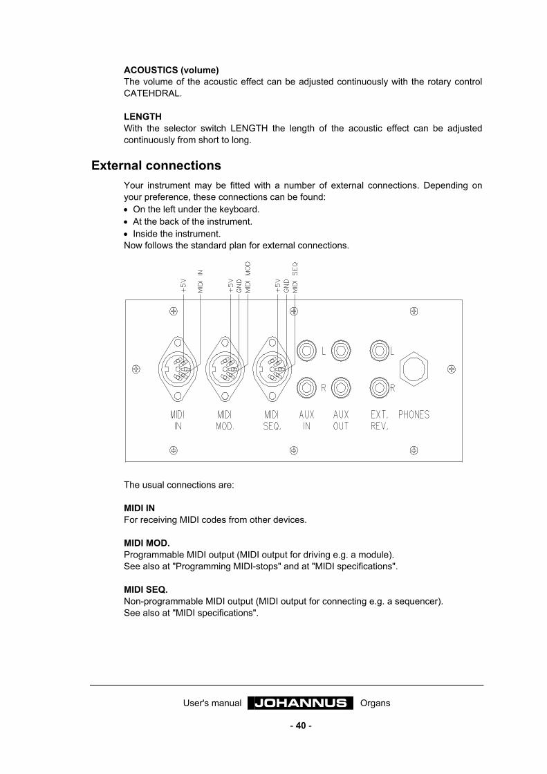
User's manual JOHANNUS Organs
- 40 -
ACOUSTICS (volume) The volume of the acoustic effect can be adjusted continuously with the rotary control CATEHDRAL. LENGTH With the selector switch LENGTH the length of the acoustic effect can be adjusted continuously from short to long.
External connections Your instrument may be fitted with a number of external connections. Depending on your preference, these connections can be found: • On the left under the keyboard. • At the back of the instrument. • Inside the instrument. Now follows the standard plan for external connections.
The usual connections are: MIDI IN For receiving MIDI codes from other devices. MIDI MOD. Programmable MIDI output (MIDI output for driving e.g. a module). See also at "Programming MIDI-stops" and at "MIDI specifications". MIDI SEQ. Non-programmable MIDI output (MIDI output for connecting e.g. a sequencer). See also at "MIDI specifications".
User's manual JOHANNUS Organs
- 41 -
AUX IN This input is meant to reproduce the sound of an external device via the amplifiers of the instrument. For example, an expander which is controlled via the MIDI MOD. of the instrument, can be played via the loudspeakers of the instrument. The volume of the device that is connected via the AUX IN, cannot be adjusted with the general volume setting or with the expression pedals (except when the external device is controlled via the MIDI MOD. of the instrument). AUX OUT This output is meant for connecting an external amplifier (stereo). EXT. REV. The EXTERN REVERB connector is especially meant for connecting a JOHANNUS external acoustics unit. This is a system that, with four separate loudspeaker boxes, imitates the spacial effect of a concert hall or a cathedral in the space where the instrument is placed. Using this output for other purposes is advised against. PHONES This connection for the headphones (stereo) is suitable for headphones with an impedance to 30Ω or higher. When using the headhones, the internal and / or external loudspeakers of the instrument are automatically switched off. The various loudspeaker channels are now evenly spread over two headphone channels. LOUDSPEAKER CONNECTIONS If your instrument is designed to be connected to an external reproduction system in the form of e.g. a pipe facade behind which there are various loudspeakers, the instrument has the required loudspeaker connectors. By means of one or more special multi-core cables, the external reproduction system can be coupled to your instrument via these connectors. Each separate core of these multi-core cables is coded with a core number as indicated on the isolation. Each (twisted) pair of wires of a supplied cable is labelled with the appropriate channel number. These channel numbers match the channel numbers on the back of a loudspeaker system or a supplied connection diagram. A twisted pair of wires consists of a core with an odd core number for the minus (–) connection and a core with an even core number for the plus (+) connection. The loudspeaker cables are always connected according to a fixed pattern: The minus (–) connection is always connected to the black (–) loudspeaker wire clamps. The plus (+) connection is always connected to the red (+) loudspeaker wire clamps. Before connecting the loudspeaker cables press the red or black terminal (on your instrument) and insert ± 1cm of the bare part of the core into the hole. After that release the red (black) terminal. To prevent a faulty connection, please see to it that only the naked end is inserted. If also the isolation goes into the terminal, the channel concerned will not work. Now follow some examples of the (standard) connections of a 4-, 6-, 8- and 12-channel instrument with the corresponding core numbers.
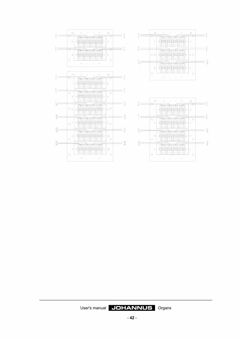
User's manual JOHANNUS Organs
- 42 -
User's manual JOHANNUS Organs
- 43 -
Choise of temperament Temperament or temperature is the arrangement of notes within an octave. In the course of time, this arrangement has continually changed and has been adapted to changing tastes or to other and newer instruments. Your instrument may allow you to choose from the following temperaments: • Equal temperament • Werckmeister III-temperament • Meantone temperament
Equal temperament At present, the usual and generally accepted temperament is the "equal" temperament. This is a tuning system based on the division of the octave into 12 equal semitones. The equality of semitones means that all other intervals are tempered, as compared with their frequency ratios. This is the normal tuning of your instrument. On an instrument tuned according to this principle music can be played in all the major and minor keys.
Werckmeister III temperament Andreas Werckmeister introduced his temperament in Germany about 1691. In this temperament the usual thirds are relatively pure. Each key has its own specific character. This was especially exploited during the Baroque period, and also in later days. Johann Mattheson wrote in 1713 that e.g. "f-minor is used to express resigned, deep, despair and fear of death". In his opinion "C-major is impertinent, but not unsuited to express feelings of joy as well".
Meantone temperament With meantone temperament the most widely used major thirds are tuned pure (e.g. c-e, d-fis, etc). Because pure thirds in chords with fifths and thirds determine whether the chord sounds pure or not, chords with pure thirds in this meantone temperament are experienced as very restful. When a chromatic scale is played in a meantone temperament, distinct differences between these halves become quite clear. With the meantone temperament it is impossible to realize pure major triads on the tones A flat, F sharp, G sharp and B. This meantone temperament was (with a few adaptations) in general use until about 1650. Music, written at this time, started from this temperament, made the most of the possibilities, and steered clear of the impossibilities. Because the half tones are different, chromatic passages sound vehement; this possibility was exploited a lot if violent emotions in the audience had to be summoned. For the "more out of tune" the chord, the more vehement the emotions. In the music from the period of about 1550-1650 many examples can be found in which the less pure harmonies were used for expressive reasons. Composers working at the time were, among others, Michael Praetorius (1571-1621) and Jan Pieterszoon Sweelinck (1562-1621). This repertoire needs, in fact, a meantone temperament, which adds an extra dimension. In our equal temperament this repertoire sounds a lot shallower and an essential dimension is.
User's manual JOHANNUS Organs
- 44 -
Using the capture system What are capture combinations?
Capture combinations or free combinations differ from fixed (preset) combinations: 1. Due to the indications on the thumb pistons you are limited by the fixed (preset)
combinations to program certain registrations to certain pistons. For example, the PP-piston cannot be programmed with many and/or loud stops.
2. The fixed combinations have only one memory group, so that only one combination can be stored per piston. The free (capture) combinations (except the Opus 1), on the other hand, have two, four or more memory groups, so that two, four or more combinations can be stored per piston.
3. Fixed combinations make it possible to reset the default stop combinations as set by the designer of the instrument.
Using the capture system is especially useful as soon as a lot of different registrations are needed to play a piece of music. It makes registration assistants unnecessary. The memory in which the capture combinations are stored is protected so that it cannot be erased when the organ is switched off or when the organ is unplugged from the main power. Parts of the capture system are (depending on the type of instrument): • Key switch MEMORY LOCK • Thumb pistons from M1, M2 or – and + • Display • SET-Piston • Pistons from 1 to 8 inclusive With the capture system, a number of personal registrations can be stored into a memory (programmed). These registrations can be recalled at any given moment. The capture system is built up from a number of memory groups. Each memory group has six or more memory locations. At each of these, a registration of your own choice can be stored. The accessories CHORUS and INTONATION 2 cannot be stored into the capture system. MIDI-stops can be stored into the capture system.
Programming capture combinations Programming a capture combination may differ from type to type (of capture system). Your instrument may be fitted with one of the following capture systems: • Capture system without a display • Capture system with 7-segment display • Capture system with LCD Now follow the descriptions for programming each of the three kinds of capture systems.

User's manual JOHANNUS Organs
- 45 -
Capture system without a display A capture system without a display is programmed as follows: 1. Select the required registration to be stored into the capture memory. 2. Select a capture memory group (M1 or M2) by pressing the M1- or M2-piston.
N.B. On Opus 1 take care that the M1-piston is pressed. If not, the registration you wish to store will not be stored into the capture memory, but in the fixed combinations memory, which inadvertently changes the original fixed combinations.
3. Press SET, hold it and next select the memory location (briefly press e.g.thumb
piston 3 (Opus 1: MF)). 4. Release first the thumb piston for the memory location (in ths example 3 or MF) and
only then the SET piston. 5. If desired write the newly programmed capture combination (e.g. M2-3 or M1-MF)
on the piece of music in which it is to be used. The personal registration is now stored into capture memory group M1 or M2 into location 3 (MF). Capture system with 7-segment display A capture system with 7-segment display is programmed as follows: 1. If you have an instrument with a general crescendo pedal and / or MIDI-stops, first
make certain that the thumb pistons CR and PGM are not pressed. This is to avoid accidentally changing a general crescendo or a programmed MIDI-stop setting.
2. "Open" the capture memory by turning key switch MEMORY LOCK a quarter of a
turn to the right. The SET-piston will now light up as a sign that the capture memory is "open".
3. Select the required registration to be stored into the capture memory. 4. Select a memory group (e.g. memory group 6) by pressing the – or the + piston
once or several times until the display shows the correct memory group (in this example the number 6).
6
5. Press SET, hold it and next select the memory location (press e.g. piston 3). 6. First release the piston for the memory location (in this example 3) and only then
the SET-piston.

User's manual JOHANNUS Organs
- 46 -
7. After programming one or more capture combinations, "close" the capture memory by turning key switch MEMORY LOCK a quarter of a turn to the left (taking the key from the switch, if necessary). The LED in the SET-piston will go off now, as a sign that the capture memory is "closed" again.
8. If desired write the newly programmed capture combination (e.g. M6-3) on the
piece of music in which this registration is to be used. Your personal registration is now stored into memory group 6 at location 3. Capture system with LCD A capture system with LCD is programmed as follows: 1. If you have an instrument with a general crescendo pedal and / or MIDI-stops, first
make certain that the thumb pistons CR and PGM are not pressed. This is to avoid accidentally changing a general crescendo or a programmed MIDI-stop settings.
2. "Open" the capture memory by turning key switch MEMORY LOCK a quarter of a
turn to the right. The SET-piston will now light up as a sign that the capture memory is "open".
3. Select the required registration to be stored into the capture memory. 4. Select a memory group (e.g. memory group Mem: 6) by pressing the – or the +
piston once or several times until the display shows the correct memory group (in this example the number 6).
M e m : 6 V o l : 1 2 T u n e : 4 4 0 T r a n s : 0 C r e s c e n d o : O f f
5. Press SET, hold it and next select the memory location (briefly press e.g. piston 3).. 6. First release the piston for the memory location (in this example 3) and only then
the SET-piston. 7. After programming one or more capture combinations, "close" the capture memory
by turning key switch MEMORY LOCK a quarter of a turn to the left (taking the key from the switch, if necessary). The LED in the SET-piston will go off now, as a sign that the capture memory is "closed" again.
8. If desired write the newly programmed capture combination (e.g. M6-3) on the
piece of music in which this registration is to be used. Your personal registration is now stored into memory group 6 at location 3.
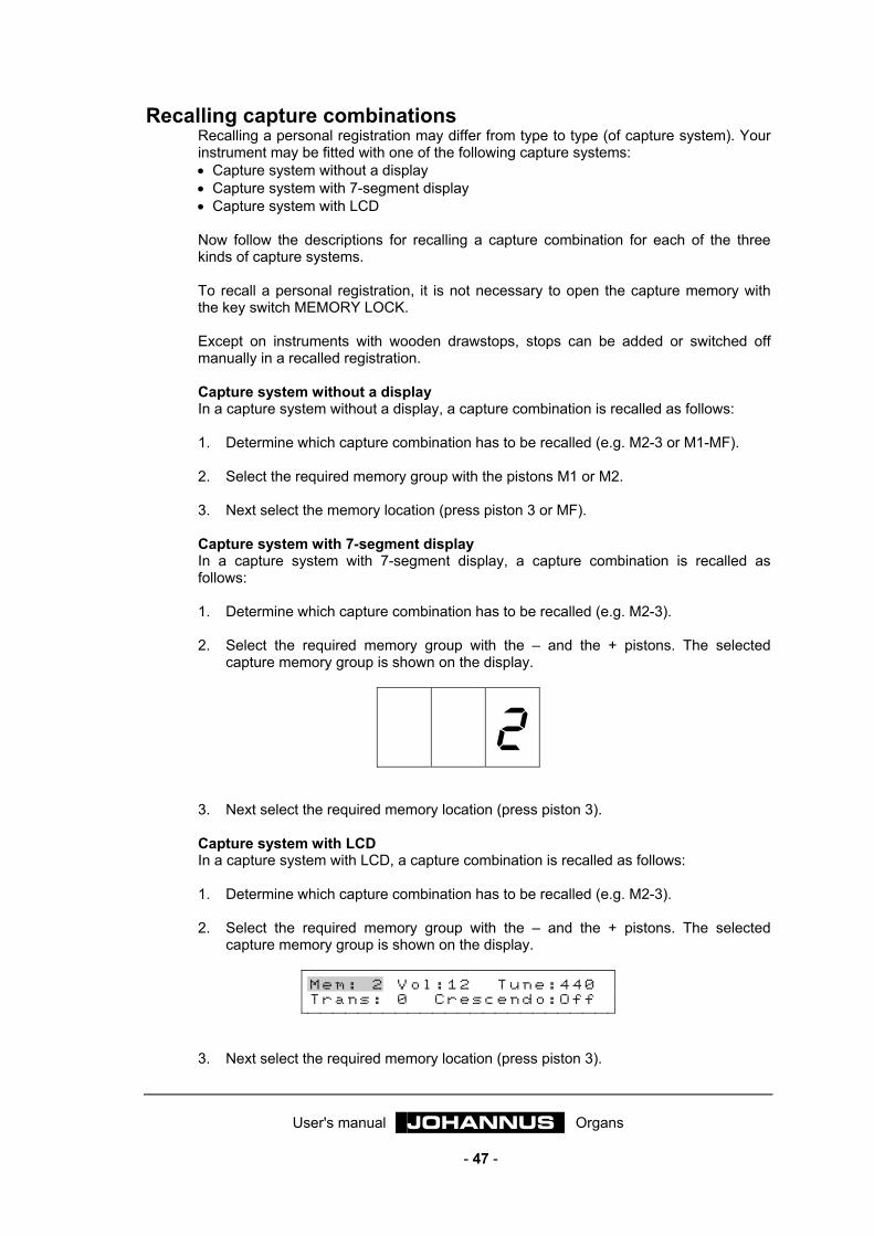
User's manual JOHANNUS Organs
- 47 -
Recalling capture combinations Recalling a personal registration may differ from type to type (of capture system). Your instrument may be fitted with one of the following capture systems: • Capture system without a display • Capture system with 7-segment display • Capture system with LCD Now follow the descriptions for recalling a capture combination for each of the three kinds of capture systems. To recall a personal registration, it is not necessary to open the capture memory with the key switch MEMORY LOCK. Except on instruments with wooden drawstops, stops can be added or switched off manually in a recalled registration. Capture system without a display In a capture system without a display, a capture combination is recalled as follows: 1. Determine which capture combination has to be recalled (e.g. M2-3 or M1-MF). 2. Select the required memory group with the pistons M1 or M2. 3. Next select the memory location (press piston 3 or MF). Capture system with 7-segment display In a capture system with 7-segment display, a capture combination is recalled as follows: 1. Determine which capture combination has to be recalled (e.g. M2-3). 2. Select the required memory group with the – and the + pistons. The selected
capture memory group is shown on the display.
2
3. Next select the required memory location (press piston 3). Capture system with LCD In a capture system with LCD, a capture combination is recalled as follows: 1. Determine which capture combination has to be recalled (e.g. M2-3). 2. Select the required memory group with the – and the + pistons. The selected
capture memory group is shown on the display.
M e m : 2 V o l : 1 2 T u n e : 4 4 0 T r a n s : 0 C r e s c e n d o : O f f
3. Next select the required memory location (press piston 3).

User's manual JOHANNUS Organs
- 48 -
Using the general crescendo When your instrument has been fitted with a general crescendo pedal, you will be able to switch on stops, in 10 or 20 steps, ranging from very soft (pianissimo) to very loud (tutti), depending on the type of instrument. The steps of the general crescendo were set in advance, according to musical standards. The general crescendo always takes precedence over hand registrations, fixed (preset) combinations and free (capture) combinations. Stops activated with the general crescendo cannot be switched off with the 0- or CAN-pistons. Reeds that have been activated by the general crescendo, can be switched off with the RO-piston. The FA-piston retains its function when the general crescendo is used. In other words: non-activated couplers which might be switched on when the general crescendo is used, remain switched off when the FA piston is pressed. The default stop combinations of each general crescendo step can always be reset into the general crescendo memory. This is only possible for all the general crescendo steps together. The personal stop combinations are lost in the process. The general crescendo memory is protected so that it cannot be erased when the organ is switched off or when the organ is unplugged from the main power.
Switching on general crescendo
Typically, the function of the general crescendo pedal is not switched on. This is to prevent a general crescendo registration accidentally to be activated by moving the general crescendo pedal. To use the general crescendo pedal, the CR-piston must be pressed. On instruments with a 7-segment display, the display will not show now a selected memory group of the capture system, but indicates to which step the general crescendo pedal is pressed down.
0 0 2 When the general crescendo pedal is back in its initial position (step 0) no number will be shown in the display.
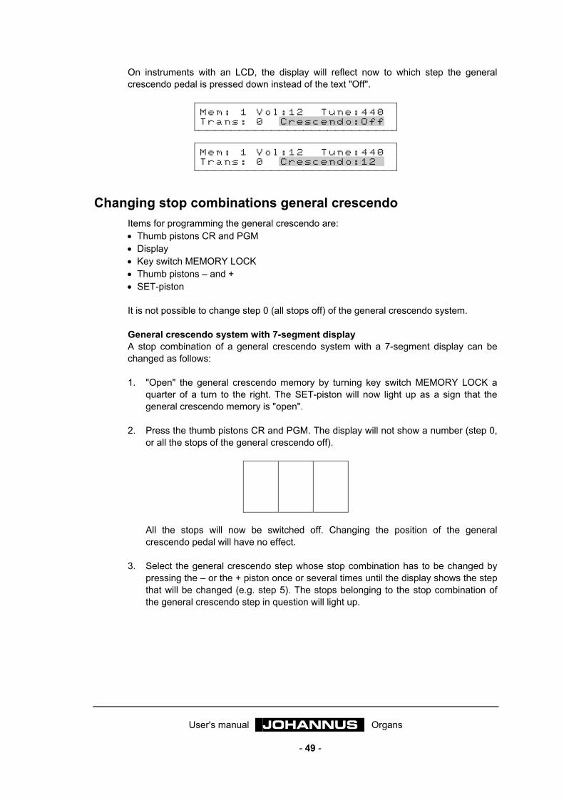
User's manual JOHANNUS Organs
- 49 -
On instruments with an LCD, the display will reflect now to which step the general crescendo pedal is pressed down instead of the text "Off".
M e m : 1 V o l : 1 2 T u n e : 4 4 0 T r a n s : 0 C r e s c e n d o : O f f
M e m : 1 V o l : 1 2 T u n e : 4 4 0 T r a n s : 0 C r e s c e n d o : 1 2
Changing stop combinations general crescendo Items for programming the general crescendo are: • Thumb pistons CR and PGM • Display • Key switch MEMORY LOCK • Thumb pistons – and + • SET-piston It is not possible to change step 0 (all stops off) of the general crescendo system. General crescendo system with 7-segment display A stop combination of a general crescendo system with a 7-segment display can be changed as follows: 1. "Open" the general crescendo memory by turning key switch MEMORY LOCK a
quarter of a turn to the right. The SET-piston will now light up as a sign that the general crescendo memory is "open".
2. Press the thumb pistons CR and PGM. The display will not show a number (step 0,
or all the stops of the general crescendo off).
All the stops will now be switched off. Changing the position of the general crescendo pedal will have no effect.
3. Select the general crescendo step whose stop combination has to be changed by
pressing the – or the + piston once or several times until the display shows the step that will be changed (e.g. step 5). The stops belonging to the stop combination of the general crescendo step in question will light up.
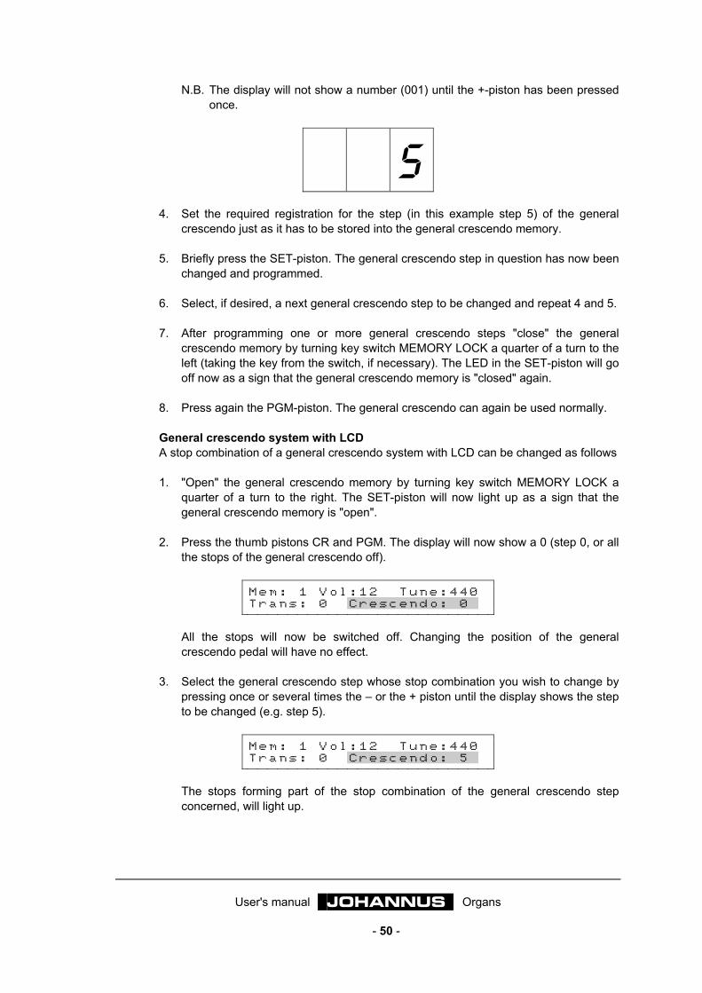
User's manual JOHANNUS Organs
- 50 -
N.B. The display will not show a number (001) until the +-piston has been pressed once.
5
4. Set the required registration for the step (in this example step 5) of the general crescendo just as it has to be stored into the general crescendo memory.
5. Briefly press the SET-piston. The general crescendo step in question has now been
changed and programmed. 6. Select, if desired, a next general crescendo step to be changed and repeat 4 and 5. 7. After programming one or more general crescendo steps "close" the general
crescendo memory by turning key switch MEMORY LOCK a quarter of a turn to the left (taking the key from the switch, if necessary). The LED in the SET-piston will go off now as a sign that the general crescendo memory is "closed" again.
8. Press again the PGM-piston. The general crescendo can again be used normally. General crescendo system with LCD A stop combination of a general crescendo system with LCD can be changed as follows 1. "Open" the general crescendo memory by turning key switch MEMORY LOCK a
quarter of a turn to the right. The SET-piston will now light up as a sign that the general crescendo memory is "open".
2. Press the thumb pistons CR and PGM. The display will now show a 0 (step 0, or all
the stops of the general crescendo off).
M e m : 1 V o l : 1 2 T u n e : 4 4 0 T r a n s : 0 C r e s c e n d o : 0
All the stops will now be switched off. Changing the position of the general crescendo pedal will have no effect.
3. Select the general crescendo step whose stop combination you wish to change by
pressing once or several times the – or the + piston until the display shows the step to be changed (e.g. step 5).
M e m : 1 V o l : 1 2 T u n e : 4 4 0 T r a n s : 0 C r e s c e n d o : 5
The stops forming part of the stop combination of the general crescendo step concerned, will light up.
User's manual JOHANNUS Organs
- 51 -
4. Set the required registration for the step in question (in this example step 5) of the general crescendo as you wish to store it into the general crescendo memory.
5. Briefly press the SET-piston. The general crescendo step in question has now been
changed and programmed. 6. Select, if desired, a next general crescendo step to be changed and repeat 4 and 5 7. After programming one or more general crescendo steps "close" the general
crescendo memory by turning key switch MEMORY LOCK a quarter of a turn to the left (taking the key from the switch, if necessary). The LED in the SET-piston will go off now as a sign that the general crescendo memory is "closed" again.
8. Press again the PGM-piston. The general crescendo is ready for normal use again.
Resetting standard stop combinations general crescendo It is always possible to restore the standard stop combinations of a programmable general crescendo pedal into the general crescendo memory. However, this is only possible for all the general crescendo steps together. The selected personal stop combinations will be lost. General crescendo system with 7-segment display The standard stop combinations of a general crescendo system with 7-segment display can be restored as follows: 1. Press the thumb pistons CR and PGM. The display will not show a number (step 0,
or all the stops of the general crescendo off).
All the stops will now be switched off. Changing the position of the general crescendo pedal will have no effect.
2. Press the 0, the CAN or the HR piston, hold it and then briefly press the SET piston. 3. First release the SET piston and only then the 0, the CAN or the HR piston. 4. Again press the PGM piston. The general crescendo pedal is now ready for normal
use again. General crescendo systeem with LCD The standard stop combinations of a general crescendo system with LCD can be restored as follows:
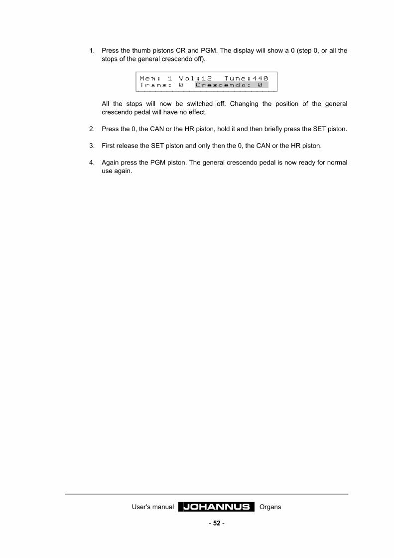
User's manual JOHANNUS Organs
- 52 -
1. Press the thumb pistons CR and PGM. The display will show a 0 (step 0, or all the stops of the general crescendo off).
M e m : 1 V o l : 1 2 T u n e : 4 4 0 T r a n s : 0 C r e s c e n d o : 0
All the stops will now be switched off. Changing the position of the general crescendo pedal will have no effect.
2. Press the 0, the CAN or the HR piston, hold it and then briefly press the SET piston. 3. First release the SET piston and only then the 0, the CAN or the HR piston. 4. Again press the PGM piston. The general crescendo pedal is now ready for normal
use again.

User's manual JOHANNUS Organs
- 53 -
Application of MIDI What is MIDI?
MIDI is the abbreviation for Musical Instruments Digital Interface. With MIDI, musical instruments can be coupled to each other, to a computer or to another MIDI device (e.g. a sequencer). Thus, it is, e.g. possible to play simultaneously both your instrument and a synthesizer or expander. The MIDI-standard is partly based on hardware. In addition, it is a description of the way in which music and sound are translated and in which communication takes place between devices equipped with MIDI-functionality. The MIDI-codes tell e.g. which key has been pressed. Components relevant to MIDI: • MIDI-connections (MIDI IN, MIDI MOD, MIDI SEQ). • MIDI-stops (or switches). • A device (e.g. synthesizer) you wish to control via MIDI. • Connection cables. The MIDI-stops may be designed as lighted thumb pistons, or as stops. With the MIDI-stops, you determine from which keyboards you wish to transmit MIDI-signals with key information to other devices.
How and what to connect? Suppose, you wish to connect an expander to a 2-manual instrument with the standard MIDI settings (see also the description of "Programming MIDI-stops". You want to play two expander voices. One from the great keyboard and the second from the swell keyboard. Follow this line of procedure: 1. Connect the expanders with the appropriate cables (MIDI- and AUDIO-cables).
ORGAN EXPANDER
AUX IN
MOD
LINE OUT IN
2. Adjust the expander so that it can receive signals via channels 1 and 2 (standard
setting for the stops MIDI GREAT and MIDI SWELL). 3. Select on your expander an instrument for each MIDI channel. If you have selected on the expander a piano for MIDI channel 1 and a harp for MIDI channel 2, the piano of the expander (possibly together with the activated stops of the great , will sound when you activate MIDI switch MIDI GREAT. When you play the swell of your instrument, the harp of the expander ((possibly together with the activated stops of the swell) , will sound when you activate MIDI switch MIDI SWELL.

User's manual JOHANNUS Organs
- 54 -
Programming MIDI-stops Your instrument has been fitted with two different MIDI outputs, one programmable and one non-programmable. The MIDI MOD is a programmable MIDI output. It enables you to use, e.g. a module/ expander optimally. The MIDI SEQ output is non-programmable. It is meant to drive e.g. a sequencer or a computer. This MIDI output gives a constant data output with all the necessary data (data dump) for e.g. a sequencer. When using the Intonat program, the MIDI SEQ output must be used to transmit data from your instrument to the PC (in fact also a data dump). When transmitting MIDI codes to e.g. a sequencer or a computer the MIDI SEQ output must be used. (see at MIDI dump) With programmable MIDI, a random module voice (1-128) can be driven via a random channel (1-16), with the MIDI-stops (MIDI GREAT; MIDI SWELL; MIDI PEDAL, etc.) of the instrument. Because channel 12 is reserved for transmitting stop data we would like to advise you not to program MIDI-stops with MIDI channel 12. If e.g. MIDI-stop MIDI GREAT 1 is programmed with patch No 7 and channel No 15, the key information will be transmitted via channel 15 and patch 7 will sound if you play on the great and stop MIDI GREAT 1 is on. Except the key information also the expression pedal information of the expression pedal is transmitted through the MIDI channel programmed for that division. In this example the MIDI codes of the Great expression pedal are also transmitted via MIDI channel 15. The infomation of the general volume, the pitch and the transposer is always transmitted through all 16 channels simultaneously. The memory has been protected so that it cannot be erased when the organ is switched off or the organ is unplugged from the main power.
Programming (hand registrations) Items for programming the MIDI-stops (switches) are: • Key switch MEMORY LOCK • Thumb pistons – and + • Display • SET-piston • PGM-piston • MIDI-stops

User's manual JOHANNUS Organs
- 55 -
Programming MIDI-stops with 7-segment display On instruments with a 7-segment display, a MIDI-stop can be programmed as follows: 1. First of all press the 0-piston (long) or the CAN piston so that all the stops go off.
Just to make certain that no MIDI-stop that already has been programmed into the memory, is changed by accident.
2. Make certain that the CR piston has not been switched on. This prevents a general
crescendo step from being changed by accident. 3. "Open" the memory by turning key switch MEMORY LOCK a quarter of a turn to the
right. The SET piston will now light up as a sign that the memory is "open" again. 4. Switch on the MIDI-stop you wish to program (e.g. MIDI SWELL). Make certain that
the other MIDI-stops are off. 5. Press the PGM-piston. The display will now show the current (latest programmed)
channel number of the switched on MIDI-stop (in this example the MIDI channel number belonging to MIDI-stop MIDI SWELL).
0 0 2
6. By pressing once or several times the – or + piston, now select the channel you
wish to assign to the MIDI-stop to be programmed. The selected MIDI channel (from 1 to 16 inclusive) is shown on the display.
0 0 6
7. Briefly press the SET piston when you have selected the required channel (e.g.
channel 6). The selected MIDI channel has now been assigned to the MIDI-stop to be programmed. After pressing (and releasing) the SET piston, the display will indicate the current patch number belonging to the MIDI-stop. In this example patch number 1.
0 0 1
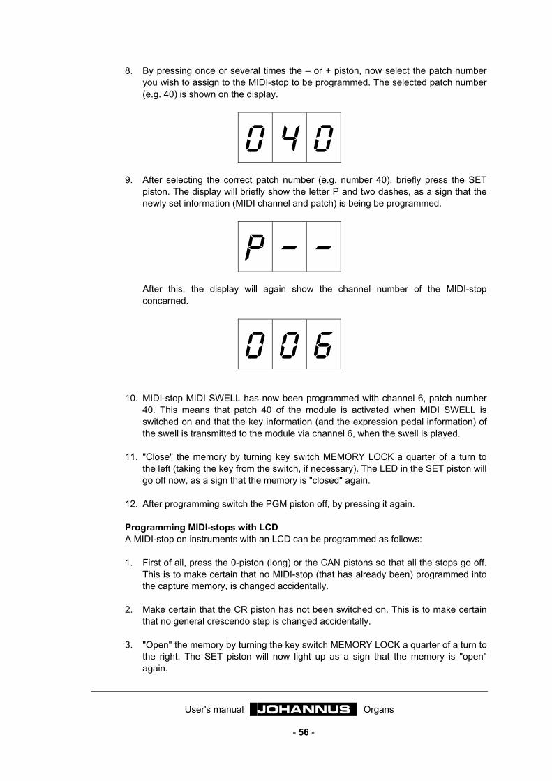
User's manual JOHANNUS Organs
- 56 -
8. By pressing once or several times the – or + piston, now select the patch number you wish to assign to the MIDI-stop to be programmed. The selected patch number (e.g. 40) is shown on the display.
0 4 0
9. After selecting the correct patch number (e.g. number 40), briefly press the SET piston. The display will briefly show the letter P and two dashes, as a sign that the newly set information (MIDI channel and patch) is being be programmed.
P – – After this, the display will again show the channel number of the MIDI-stop concerned.
0 0 6
10. MIDI-stop MIDI SWELL has now been programmed with channel 6, patch number
40. This means that patch 40 of the module is activated when MIDI SWELL is switched on and that the key information (and the expression pedal information) of the swell is transmitted to the module via channel 6, when the swell is played.
11. "Close" the memory by turning key switch MEMORY LOCK a quarter of a turn to
the left (taking the key from the switch, if necessary). The LED in the SET piston will go off now, as a sign that the memory is "closed" again.
12. After programming switch the PGM piston off, by pressing it again. Programming MIDI-stops with LCD A MIDI-stop on instruments with an LCD can be programmed as follows: 1. First of all, press the 0-piston (long) or the CAN pistons so that all the stops go off.
This is to make certain that no MIDI-stop (that has already been) programmed into the capture memory, is changed accidentally.
2. Make certain that the CR piston has not been switched on. This is to make certain
that no general crescendo step is changed accidentally. 3. "Open" the memory by turning the key switch MEMORY LOCK a quarter of a turn to
the right. The SET piston will now light up as a sign that the memory is "open" again.
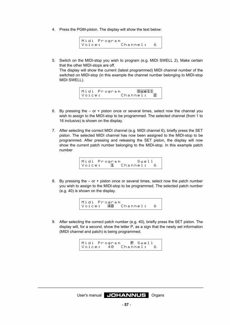
User's manual JOHANNUS Organs
- 57 -
4. Press the PGM-piston. The display will show the text below:
M i d i P r o g r a m V o i c e : C h a n n e l : 6
5. Switch on the MIDI-stop you wish to program (e.g. MIDI SWELL 2). Make certain
that the other MIDI-stops are off. The display will show the current (latest programmed) MIDI channel number of the switched on MIDI-stop (in this example the channel number belonging to MIDI-stop MIDI SWELL).
M i d i P r o g r a m S w e l l V o i c e : C h a n n e l : 2
6. By pressing the – or + piston once or several times, select now the channel you
wish to assign to the MIDI-stop to be programmed. The selected channel (from 1 to 16 inclusive) is shown on the display.
7. After selecting the correct MIDI channel (e.g. MIDI channel 6), briefly press the SET
piston. The selected MIDI channel has now been assigned to the MIDI-stop to be programmed. After pressing and releasing the SET piston, the display will now show the current patch number belonging to the MIDI-stop. In this example patch number
M i d i P r o g r a m S w e l l V o i c e : 1 C h a n n e l : 6
8. By pressing the – or + piston once or several times, select now the patch number
you wish to assign to the MIDI-stop to be programmed. The selected patch number (e.g. 40) is shown on the display.
M i d i P r o g r a m V o i c e : 4 0 C h a n n e l : 6
9. After selecting the correct patch number (e.g. 40), briefly press the SET piston. The
display will, for a second, show the letter P, as a sign that the newly set information (MIDI channel and patch) is being programmed.
M i d i P r o g r a m P S w e l l V o i c e : 4 0 C h a n n e l : 6
User's manual JOHANNUS Organs
- 58 -
10. MIDI-stop MIDI SWELL has now been programmed with channel 6, patch number 40. This means that patch 40 of the module is switched on when MIDI SWELL is activated and that the key information (and expression pedal information) of the swell is transmitted to the module via channel 6, when the swell is played.
11. "Close" the memory by turning key switch MEMORY LOCK a quarter of a turn to
the left (taking the key from the switch, if necessary). The LED in the SET piston will go off now, as a sign that the memory is "closed" again.
12. After programming, switch the PGM piston off, by pressing it again.
Programming (into the capture system) What this, in fact, boils down to, is storing a patch into the capture memory of your instrument, whether or not in combination with a number of normal organ stops. In programming MIDI-stops into the capture system, several channels / patch numbers can be assigned to one MIDI-stop by using several capture memory locations. In this way a 3-manual instrument with an expanded capture system (capture system with generals and separates) with 8 memory groups, allows 135 different settings to be programmed per MIDI-stop (1 x hand registration; 6 x presets; 64 x generals and 64 x separates). In all 4x135 = 540 different settings can be programmed for the whole (3-manual) instrument. Items for programming the MIDI-stops are: • Key switch MEMORY LOCK • Thumb pistons – and + • Pistons from 1 to 8 inclusive • Display • SET piston • PGM piston • MIDI-stops Programming MIDI-stops with 7-segment display On instruments with a 7-segment display a MIDI-stop can be programmed into the capture system as follows: 1. Make certain that the CR and PGM pistons have not been switched on, if you have
an instrument with a programmable general crescendo pedal. This is to make certain that no stop combination of the general crescendo step or an already programmed MIDI-stop is changed accidentally.
2. "Open" the memory by turning key switch MEMORY LOCK a quarter of a turn to the
right. The SET piston will now light up as a sign that the memory is "open". 3. Switch on the MIDI-stop you wish to program (e.g. MIDI SWELL) together with (if
required) a number of stops which have to be stored into the capture memory.

User's manual JOHANNUS Organs
- 59 -
4. First store this registration into the required capture memory (see "Using the capture system"). This can be both a capture memory of the generals and of the separates (if present). Opm: 1. If the set registration is not stored into the capture memory first, the
programmed hand registration of the MIDI-stop in question will (unintentionally) be changed.
2. Concerning the separates, MIDI-stops can obviously only be programmed into the accompanying separates. MIDI SWELL can only be programmed into the separates of the swell and not into the separates of the great, for instance.
5. Press the PGM-piston. The display will now show the current (latest programmed)
MIDI channel number of the switched on MIDI-stop (in this example, the MIDI channel number belonging to MIDI-stop MIDI SWELL).
6. By pressing the – or + piston once or several times, now select the MIDI channel
that is to be assigned to the MIDI-stop to be programmed. The selected MIDI channel (from 1 to 16 inclusive) is shown on the display.
0 0 6
7. After selecting the correct MIDI channel (e.g. MIDI channel 6), briefly press the SET
piston. The selected MIDI channel has now been assigned to the MIDI-stop to be programmed. After pressing (and releasing again) the SET piston, the display will show the current patch number, belonging to the MIDI-stop. In this example patch number 1.
0 0 1
8. By pressing the – or + piston once or several times, select the patch number you
wish to assign to the MIDI-stop to be programmed. The selected patch number (e.g. 40) is shown on the display.
0 4 0
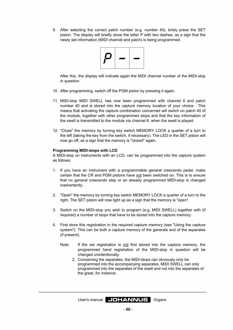
User's manual JOHANNUS Organs
- 60 -
9. After selecting the correct patch number (e.g. number 40), briely press the SET piston. The display will briefly show the letter P with two dashes, as a sign that the newly set information (MIDI channel and patch) is being programmed.
P – – After this, the display will indicate again the MIDI channel number of the MIDI-stop in question.
10. After programming, switch off the PGM piston by pressing it again. 11. MIDI-stop MIDI SWELL has now been programmed with channel 6 and patch
number 40 and is stored into the capture memory location of your choice . This means that activating the capture combination concerned will switch on patch 40 of the module, together with other programmed stops and that the key information of the swell is transmitted to the module via channel 6, when the swell is played.
12. "Close" the memory by turning key switch MEMORY LOCK a quarter of a turn to
the left (taking the key from the switch, if necessary). The LED in the SET piston will now go off, as a sign that the memory is "closed" again.
Programming MIDI-stops with LCD A MIDI-stop on instruments with an LCD, can be programmed into the capture system as follows: 1. If you have an instrument with a programmable general crescendo pedal, make
certain that the CR and PGM pistons have not been switched on. This is to ensure that no general crescendo step or an already programmed MIDI-stop is changed inadvertently.
2. "Open" the memory by turning key switch MEMORY LOCK a quarter of a turn to the
right. The SET piston will now light up as a sign that the memory is "open". 3. Switch on the MIDI-stop you wish to program (e.g. MIDI SWELL) together with (if
required) a number of stops that have to be stored into the capture memory. 4. First store this registration in the required capture memory (see "Using the capture
system"). This can be both a capture memory of the generals and of the separates (if present). Note: If the set registration is not first stored into the capture memory, the
programmed hand registration of the MIDI-stop in question will be changed unintentionally.
2. Concerning the separates, the MIDI-stops can obviously only be programmed into the accompanying separates. MIDI SWELL can only programmed into the separates of the swell and not into the separates of the great, for instance.
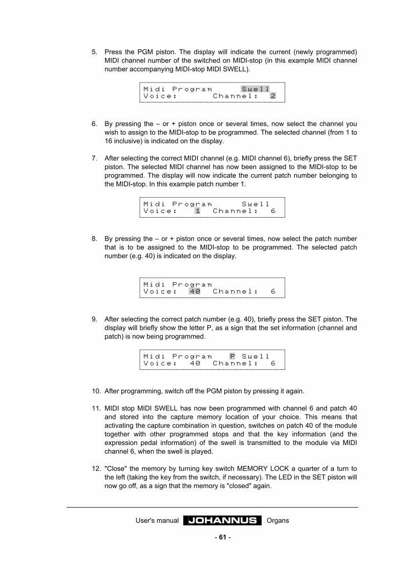
User's manual JOHANNUS Organs
- 61 -
5. Press the PGM piston. The display will indicate the current (newly programmed) MIDI channel number of the switched on MIDI-stop (in this example MIDI channel number accompanying MIDI-stop MIDI SWELL).
M i d i P r o g r a m S w e l l V o i c e : C h a n n e l : 2
6. By pressing the – or + piston once or several times, now select the channel you
wish to assign to the MIDI-stop to be programmed. The selected channel (from 1 to 16 inclusive) is indicated on the display.
7. After selecting the correct MIDI channel (e.g. MIDI channel 6), briefly press the SET
piston. The selected MIDI channel has now been assigned to the MIDI-stop to be programmed. The display will now indicate the current patch number belonging to the MIDI-stop. In this example patch number 1.
M i d i P r o g r a m S w e l l V o i c e : 1 C h a n n e l : 6
8. By pressing the – or + piston once or several times, now select the patch number
that is to be assigned to the MIDI-stop to be programmed. The selected patch number (e.g. 40) is indicated on the display.
M i d i P r o g r a m V o i c e : 4 0 C h a n n e l : 6
9. After selecting the correct patch number (e.g. 40), briefly press the SET piston. The
display will briefly show the letter P, as a sign that the set information (channel and patch) is now being programmed.
M i d i P r o g r a m P S w e l l V o i c e : 4 0 C h a n n e l : 6
10. After programming, switch off the PGM piston by pressing it again. 11. MIDI stop MIDI SWELL has now been programmed with channel 6 and patch 40
and stored into the capture memory location of your choice. This means that activating the capture combination in question, switches on patch 40 of the module together with other programmed stops and that the key information (and the expression pedal information) of the swell is transmitted to the module via MIDI channel 6, when the swell is played.
12. "Close" the memory by turning key switch MEMORY LOCK a quarter of a turn to
the left (taking the key from the switch, if necessary). The LED in the SET piston will now go off, as a sign that the memory is "closed" again.
User's manual JOHANNUS Organs
- 62 -
Programming several MIDI-stops into the capture system Several MIDI-stops (whether or not in combination with a number of organ voices) can be programmed into one capture memory. When programming several MIDI-stops into one capture memory, you should start at the lowest numbered MIDI-stop. The order of MIDI-stops is always: 1=Choir, 2=Great, 3=Swell, 4=Solo, etc. last=Pedal. If your instrument does not have a choir manual, Great is the division with the lowest MIDI-stop. Programming several (in this example MIDI GREAT; MIDI SWELL and MIDI PEDAL) MIDI-stops into one capture memory location goes as follows: 1. If you have an instrument with a programmable general crescendo pedal, make
certain that the CR and PGM pistons have not been switched on. This is to ensure that no general crescendo step or an already programmed MIDI-stop is changed inadvertently.
2. Switch on the three MIDI switches (together with programmed organ voices). 3. "Open" the memory with key switch MEMORY LOCK. 4. First store this registration into the required capture memory (see "Using the
capture system"). 5. Press the PGM piston. 6. Select with the thumb pistons – and + the required MIDI channel for MIDI GREAT
(MIDI-stop with the lowest number). 7. Briefly press the SET piston. 8. Select with the thumb pistons – and + the patch number for MIDI GREAT 1. 9. Briefly press the SET piston. The settings for MIDI GREAT will now be
programmed. 10. Now switch off the stop MIDI GREAT. 11. Select with the thumb pistons – and + the channel for MIDI SWELL (this is now the
MIDI-stop with the lowest number). 12. Briefly press the SET piston. 13. Select with the thumb pistons – and + the patch number for MIDI SWELL. 14. Briefly press the SET piston. The settings for MIDI SWELL will now be
programmed. 15. Now switch off stop MIDI SWELL. 16. Select with the thumb pistons – and + the channel for MIDI PEDAL (this is now the
MIDI-stop with the lowest number).

User's manual JOHANNUS Organs
- 63 -
17. Briefly press the SET piston. 18. Select with the thumb pistons – and + the patch number for MIDI PEDAL. 19. Briefly press the SET piston. The settings for MIDI PEDAL will now be
programmed. 20. Switch PGM off. 21. "Close" the memory with the key switch MEMORY LOCK.
User's manual JOHANNUS Organs
- 64 -
Sound reproduction systems Sound reproduction of your instrument may be realized in different ways. The usual ways will be briefly described below. Other combinations of sound reproduction systems required for a certain room or specific application are also possible.
Internal single reproduction system In single internal sound reproduction all the loudspeakers are inside the instrument. Depending on the design, these loudspeakers may sound forward, upward or backward. On instruments with separate divisions (each division having its own amplifiers/loudspeakers) it is possible to have the loudspeakers of the various divisions sounding to several directions. For example, the loudspeakers of the great and pedal divisions may be sounding forward and the loudspeakers of the swell division backward. In this way the effect of a direct sounding great and pedal division and an indirect sounding swell division can be realized.
Internal double reproduction system For this system of reproduction all the (or nearly all the) channels / loudspeakers are designed double. One set of loudspeakers is sounding backward and one set forward. With a three-position switch the loudspeakers pointing forward can be entirely switched off, be allowed to join in softly, or to sound normal. This way you can choose between an instrument sounding more direct or less direct. This system of reproduction is standard on models "Van Rhijn" and "Van Eijck".
External single reproduction system In single external sound reproduction, all the loudspeakers are in a front outside the instrument. Depending on the design, the various loudspeakers may be sounding forward, upward or backward. On instruments with separate divisions (each division having its own amplifiers / loudspeakers) it is possible to have the loudspeakers of the various divisions sounding to several directions. For example, the loudspeakers of the great and pedal divisions may be sounding forward and the loudspeakers of the swell division upward or backward. In this way the effect of a direct sounding great and pedal division and an indirect sounding swell division can be realized.
External double reproduction system In this way of reproduction all the channels / loudspeakers are designed double. If your instrument has been fitted with a three-position switch, this enables you to choose between reproduction via the one, the other or both fronts.
User's manual JOHANNUS Organs
- 65 -
Internal with external reproduction system In a combination of an internal with an external reproduction system all the channels have been connected to a loudspeaker front.
• The built-in loudspeakers / channels can be: • Three monitor loudspeakers / channels through which the full organ sounds. • A number of channels equal to the external reproduction system (max. nine
loudspeakers / channels).
Three position switch Instruments with several reproduction systems may have been fitted with a 3-position switch. This switch enables you to choose between reproduction via the one, the other or both fronts. The commonest configuration is a 3-position switch which enables you to choose between Internal, Both (where the internal loudspeakers sound somewhat softer) or External.
Switchboard Smaller instruments do not have a 3-position switch. Instead, a switchboard enables the correct configuration to be set inside your instrument. Basically only once. It is not advisable to change this setting. This setting can be installed or changed only by qualified technicians. The configurations that can be realized with the switchboard are: • Internal normal volume • External normal volume • External normal volume + internal softer (via resistors on switch board) • Internall normal volume + external softer (via resistors on switch board)
Antiphonal On an instrument with separate divisions (each division having its own amplifiers / loudspeakers) one or more divisions may be connected to a second front. The division concerned can be switched from the main front to e.g. a front behind the choir, by means of a stop or a switch ANTIPHONAL.
User's manual JOHANNUS Organs
- 66 -
Special functions thumb pistons By keeping a certain combination of thumb pistons pressed while your instrument is switched on, certain settings can be changed. We advise you to be very careful with this to prevent personal settings from being lost. By pressing a certain combination of thumb pistons while your instrument is on, certain settings can be transmitted via MIDI to an external device.
Resetting factory intonation It is possible that you, after using the intonation program, for any reason whatever, wish to reset the default factory intonation on your instrument. In this process the intonation data set by you, the JOHANNUS dealer, or the JOHANNUS voicing technician are lost. Should you wish to keep this data, it should be stored as a file in your computer with the help of the intonation program. Resetting the factory intonation can be done as folllows: 1. Switch off the instrument. 2. Press thumb pistons 1 + 8 of the capture system.
Obs: 1. On instruments with several groups of pistons 1 to 8 inclusive (separates and generals, see at "1 - 8") the pistons 1 + 8 of the generals must be pressed.
2. On Opus 1the pistons PP + M1 must be pressed. 3. On Opus 5 the pistons SET + M2 must be pressed, if the instrument does
not have several groups of pistons 1 to 8 inclusive. 3. Switch on the instrument while holding the thumb pistons 1 + 8 (or PP + M1 or
SET + M2). 4. Release the thumb pistons only after the 0-, the Can or the HR pistons have come
on. (Opus 1: after the SET piston has come on.)
Clearing the capture memory When programming stop combinations into the capture system, you may wish to start with an empty capture memory Instead of programming each memory without any stops being switched on, this can be done faster. Clearing the capture memory is only possible for the entire capture memory. In the process all the programmed capture combinations are lost. Clearing the capture memory is done as follows: 1. Switch off the instrument. 2. Press thumb pistons 2 + 7 of the capture system.
Obs: 1. On instruments with several groups of pistons 1 to 8 inclusive (separates and generals, see at "1 - 8") the pistons 2 + 7 of the generals must be pressed.
2. On Opus 1the pistons P + 0 must be pressed. 3. On Opus 5 the pistons 1 + 6 must be pressed, if the instrument does not
have several groups of pistons 1 to 8 inclusive.
User's manual JOHANNUS Organs
- 67 -
3. Switch on the instrument while holding the thumb pistons 1 + 8 (or P + 0 or 1 + 6). 4. Release the thumb pistons only after the 0-, the Can or the HR pistons have come
on. (Opus 1: after the SET piston has come on.)
Resetting standard MIDI-stop settings If after programming the MIDI-stops, you wish to restore the standard factory settings, there is no need to go through the entire programming cycle for all the MIDI-stops. Depending on the number of keyboards of your instrument, the standard settings are: 2-manual instrument: MIDI GREAT: Channel number 1 Patch number 1 MIDI SWELL: Channel number 2 Patch number 1 MIDI PEDAL: Channel number 3 Patch number 1 3-manual instrument: MIDI CHOIR: Channel number 1 Patch number 1 MIDI GREAT: Channel number 2 Patch number 1 MIDI SWELL: Channel number 3 Patch number 1 MIDI PEDAL: Channel number 4 Patch number 1 4-manual instrument: MIDI CHOIR: Channel number 1 Patch number 1 MIDI GREAT: Channel number 2 Patch number 1 MIDI SWELL: Channel number 3 Patch number 1 MIDI SOLO: Channel number 4 Patch number 1 MIDI PEDAL: Channel number 5 Patch number 1 (See also at MIDI specifications) Resetting the standard MIDI-stops is only possible for all the MIDI-stops simultaneously. All the MIDI-stop settings as programmed by you will be lost. Now follows the shortened procedure for resetting the standard MIDI-stop settings: 1. Switch off the instrument. 2. Press thumb pistons 3 + 6 of the capture system.
Obs: 1. On instruments with several groups of pistons 1 to 8 inclusive (separates and generals, see at "1 - 8") the pistons 3 + 6 of the generals must be pressed.
2. On Opus 1the pistons MF + T must be pressed. 3. On Opus 5 the pistons 2 + 5 must be pressed, if the instrument does not
have several groups of pistons 1 to 8 inclusive. 3. Switch on the instrument while holding the thumb pistons 3 + 6 (or MF + T or 2 + 5). 4. Release the thumb pistons only after the 0-, the Can or the HR pistons have come
on. (Opus 1: after the SET piston has come on.)
Resetting standard fixed (preset) combinations After changing the fixed (preset) combinations you may wish to restore the standard factory settings. Resetting the standard fixed (preset) combinations is only possible for all the presets simultaneously. All the fixed (preset) combinations as programmed by you will be lost.

User's manual JOHANNUS Organs
- 68 -
Resetting the standard fixed (preset) combinations is done as follows: 1. Switch off the instrument. 2. Press thumb pistons 4 + 5 of the capture system.
Obs: 1. On instruments with several groups of pistons 1 to 8 inclusive (separates and generals, see at "1 - 8") the pistons 4 + 5 of the generals must be pressed.
2. On Opus 1the pistons F + FF must be pressed. 3. On Opus 5 the pistons 3 + 4 must be pressed, if the instrument does not
have several groups of pistons 1 to 8 inclusive. 3. Switch on the instrument while holding the thumb pistons 3 + 6 (or F + FF or 3 + 4). 4. Release the thumb pistons only after the 0-, the Can or the HR pistons have come
on. (Opus 1: after the SET piston has come on.)
Transmitting memory content (MIDI dump) It is possible to store all the registration data you have programmed into the memory of your instrument as a file on e.g. the hard disk of a computer or (with the help of a sequencer) on a disc. All the registration data stored into the memory of your instrument is then transmitted to the connected device (MIDI dump) via the MIDI SEQ. output. The registration data stored as a file in your computer or on a disc can be restored into the memory of your instrument by uploading this data to your instrument via MIDI IN. The registration data is then automatically restored to the memory of your instrument. It is only possible to restore all the data simultaneously to the memory of your instrument. It is not possible to restore e.g. only the capture data or the general crescendo data to your instrument. The entire memory of your instrument is overwritten in one go, so that all the registration data contained in it is lost. Registration data is understood to mean the following: • Free (capture) combinations • Fixed (preset) combinations • General crescendo combinations • MIDI-stop data • Programmed volume, transposer and tune settings The registration data can be transmitted from your instrument (via the MIDI SEQ. output) to another device by briefly pressing pistons 1 + 6. Opm: 1. On instruments with several groups of pistons 1 to 8 inclusive (separates and
generals, see at "1 - 8") pistons 1 + 6 of the generals must be pressed. 2. On the OPUS 1, the pistons PP + T must be pressed. 3. On the OPUS 5, pistons SET + 5 must be pressed, if the instrument does not
have
User's manual JOHANNUS Organs
- 69 -
Maintenance Cabinet
The cabinet is finished partly with wood veneer and partly with solid wood. The cabinet can be wiped with an ordinary, moist cloth or chamois and polished with a dry non-fluffy cloth. We advise against using teak oil, because this will damage the varnish. Direct sunlight may discolour the cabinet. This applies especially to natural wood.
Keyboards When your instrument is fitted with synthetic keyboards, you can treat the keys as the cabinet. Tiny scratches on the keys, formed in the long run by playing the instrument, can be removed with the help of car polish. NEVER try to remove spots with corrosive fluids such as thinner, acetone, etc.. This will irrevocably damage the keyboards of your instrument.
Pipes When your instrument has a pipe front, we advise you to never touch the pipes. The acid of human skin will corrode the pipes made of an alloy of tin and lead, irrevocably. The tin lead alloy is very soft material. Dusting the pipes, even if a soft cloth is used for this, will irrevocably leave tiny scratches on the surface. If the labia of the pipes are gold plated, they should not be touched, dusted or sponged either. This will cause the thin layer of gold paint on the labia to be damaged irreparably.
Warranty When you purchased your instrument, you were given a certificate of warranty. Read the terms carefully and mail the bottom part of the certificate to JOHANNUS Orgelbouw b.v. at Ede, The Netherlands as soon as possible. (See Information for the full address) Again we wish to draw your attention to the fact that alterations made to the instrument or unexpert treatment may cause the warranty to be nullified. It is possible to conclude a contract for periodical maintenance of your instrument. For further information, please contact JOHANNUS Orgelbouw b.v. at Ede.

User's manual JOHANNUS Organs
- 70 -
Information If you want more information about your instrument or on other products supplied by JOHANNUS Orgelbouw b.v. or for a service request, please contact, write, phone, fax or e-mail: JOHANNUS Orgelbouw b.v., Keplerlaan 2, 6716 BS EDE. PO Box 459, 6710 BL EDE (THE NETHERLANDS) Tel.: + 31 318 63 74 03 Fax: + 31 318 62 22 38 E-mail: [email protected] JOHANNUS has an interesting website with topical information about JOHANNUS Orgelbouw, and their products. The website address is: http://www.johannus.com

User's manual JOHANNUS Organs
- 71 -
MIDI Implementation chart JOHANNUS Organs Date: March 2003 MIDI Implementation Chart Version 1.00
Functions Transmitted Recognized Remarks
Basic Channel
Default Changes
See MIDI Specs See MIDI Specs
See MIDI Specs Y1 See MIDI Specs
Mode Default Messages Altered
Mode 3 N * * * * * * * *
Mode 3 N N
Note Number
True Voice
36 - 96 * * * * * * * *
Velocity Note ON Note OFF
9nH (v=64) 9nH (v=0)
9nH v=1 - 127 9nH v=0, 8nH v=*
*=irrelevant
After Touch
Keys Channels
N N
Pitch Bend N
Control Change
711
100/101/6100/101/6
Y Y Y Y
General Volume Expression Pedals Pitch Transposer
Program Change
: True#
See MIDI Specs * * * * * * * *
See MIDI Specs See MIDI Specs
See MIDI Specs See MIDI Specs
System Exclusive See MIDI Specs See MIDI Specs See MIDI Specs
Common : Song Pos : Song Sel : Tune
N N N
N N N
System Real Time
: Clock : Commands
N N
N N
Aux
: Reset All Controller: Local ON/OFF : All Notes OFF : Active Sense : Reset
N N N N N
N N N N N
Notes 1 Depends on number of divisions Mode 1: OMNY ON, POLY Mode 3: OMNY OFF, POLY
Mode 2: OMNY ON, MONO Mode 4: OMNY OFF, MONO
Y=YES N=NO

User's manual JOHANNUS Organs
- 72 -
MIDI specifications Below the specifications of the (standard English) MIDI implementation chart are worked out in detail.
Default basic channels (transmitted/recognized) 1-manual instruments: 1 = keyboard; 12 = stops. 2-manual instruments with standard keyboard order: 1 = great; 2 = swell; 3 = pedal and 12 = stops. 3-manual instruments with standard keyboard order: 1 = choir; 2 = great; 3 = swell; 4 = pedal and 12 = stops. 4-manual instruments with standard keyboard order: 1 = choir; 2 = great; 3 = swell; 4 = solo; 5 = pedal and 12 = stops. 5- (and more) manual instruments: Depends on keyboard order.
Basic channel changes (transmitted) 1-manual instrument with MIDI-stop: 1 = keyboard; 12 = stops. 2-manual instruments with MIDI-stops and standard keyboard order: 1 = great; 2 = swell; 3 = pedal; 12 = stops. Instruments with programmable MIDI-stops (PGM function): 1 - 16
Control changes (transmitted) Controller 7 (07h) = General Volume, with volume values 52 (34h) - 127 (7Fh). Controller 11 (0Bh) = Expr. pedals, with volume values 63 (3Fh) - 127 (7Fh). Controller 6 (06h) = Pitch, with pitch values 33 (21h) - 95 (5Fh). The pitch value 64 (40h) = A=440Hz. To the pitch applies: LSB 100 (64h) 1 (01h) en het MSB 101 (65h) 0 (00h). Transposer, with transposer values 61 (3Dh) - 67 (43h). The transposer value 64 (40h) = A=440Hz. To the transposer applies: LSB 100 (64h) 2 (02h) en het MSB 101 (65h) 0 (00h).

User's manual JOHANNUS Organs
- 73 -
Control changes (recognized) Controller 7 (07h) = General Volume, with volume values 0 (00h) - 127 (7Fh). Controller 11 (0Bh) = Expr. pedals, with volume values.0 (00h) - 127 (7Fh).
Program changes (transmitted) Instruments without programmable MIDI-stops: Dependent on number and order of stops. Instruments with programmable MIDI-stops: 1-128
Program changes (recognized) All instruments: Dependent on number and order of stops.
System exclusive messages (transmitted/recognized) All "sys ex (system exclusive) messages" look the same for the greater part. The first 7 bytes and the last byte are always the same. Only the value of the 8th byte varies. Now follows the "sys ex (system exclusive) messages" as generally used by JOHANNUS: F0 00 4A 4F 48 41 53 XX F7 (hexadecimal) In describing the "sys ex (system exclusive) messages" only the value of the 8th byte (XX) will be stated and from which output it is transmitted. All stops off The "all stops off"code is 7F. This code is transmitted via the MIDI SEQ. output when the 0-, CAN, or HR pistons are pressed long. When an "all stops off"code is received, all the stops on your instrument are switched off. Thumb piston values When a piston is pressed, a "sys ex code" is transmitted via the MIDI MOD output with the value of piston that is pressed. (e.g. PP = 00 P = 01) These codes only matter when a JOHANNUS sound module is connected to your instrument.
Other MIDI-codes (transmitted) Long pressing 0-, CAN, or HR pistons: Apart from the "sys ex" code and "all stops off", all the current volume settings are transmitted via the MIDI SEQ. output, when the 0-, CAN, or HR pistons are pressed long.
User's manual JOHANNUS Organs
- 74 -
Registration On a pipe organ, the sound of a rank of pipes is switched on or off with stops. By varying the stops, an organist can add dynamic and other nuances. This means that some knowledge of the traditional pipe organ is necessary to be able to registrate. Organists will have to be acquainted with the timbres of the different stops. Hence this short note about the types of organ stops. The various stop names usually show the footage, e.g. 8 feet. This means that the tallest pipe (great octave-C) of this open stop measures 8 feet (about 244 cm). A stop with the indication 16 feet (488 cm) sounds an octave lower. Organ pipes can be divided into two main groups: • flues • reeds
Flues The principle of tone generation with flues is the same as with the recorder. Flues occur in two versions: open or (semi) stopped. An example of a semi-stopped pipe is the Rohrflute. On the lid an (open) pipe (rohr) has been soldered. An example of an open labial is the Principal. The pipes of this stop are usually placed in the front of a pipe organ. Labial stops can be subdivided into the following families: Principals Prestant, Octave, Twelfth, Super Octave, Mixture, Scharff, Cymbel, Rauschpfeife and Sesquialtera, belong to the family of principals. These last five stops activate several pipes (of different pitch) per key. They are called mixtures (compounds). Flutes Among others, Hohlflöte, Gedackt, Bourdon, Subbass, Nasard, Spitzflöte, Gemshorn and Rohrflute, belong to the flute stops, both open and stopped, metal or wooden. Strings The string stops such as: Viola di Gamba and Salicional belong to the family of the narrow-scaled, open labial pipes.
Reeds In reeds the wind is driven through the foot-hole into the shallot; this causes the reed to vibrate. This vibration is amplified and "coloured" by the air column into the "resonator". The Bassoon, Trumpet, Schalmey, etc. belong to the reeds with a long funnel-shaped resonator. Fagotto, Dulciana, Krummhorn, etc. belong to the group with a cylindrical resonator. Regal, Vox Humana and Rankett belong to the group with a short resonator, etc.