handbook on power system maintenance and operations for
TRANSCRIPT

1
HANDBOOK ON POWER SYSTEM
MAINTENANCE AND OPERATIONS
FOR TNEB ENGINEERS
VOL - I
BY
Er. C. Kaliyaperumal
(Retd CE OPERATIONS/TANGEDCO)

2
SS MAINTENANCE GUIDE
ள்
1. 110 kV, 33 kV, 11 kV fault level ஐ SS display
.
2. equipments failure earthing system
. ,
. Fault level , 500
( 500
)
.
3.
.
SS
. ,
despite his union activities.
, / ஐ
, ,
.
.

3
.
.
.
. . , .
4. .
, ஏ SSஏ
. ,
, ஏ /SS ஏ , ER . ,
,
. 2.0 ஒ ,
5.0 ஒ
.
.
.
.
.
5. SS , ER . SS
ER .
.
6. . ,
/ .
. ,
, . ஏ ,

4
. AE/SS
. , SS
,
.
7. ,
. , ,
. ,
. ,
. .
. . . . .
8. , .
11 ,
.
.
, sp. gr.
. , .
, , .
sp. gravity
. , sp. gr. ஏ
. 5 deg cen 0.003
.

5
9. sp. gr. 0.03 2.50 Voltage per
cell sp. gr. . quick/equalising
charging .
, ஒ
.
Quick charging
. ஒ .
.
10. 110kV SS 30 Volts battery system .
110V battery .
.
. .
.
.
.
11. VRLA Battery, maintenance free .
not reliable,. Flooded lead acid battery flexible &
reliable and easily maintanable.
12. Battery,quick charging
.
. , sp. Gr. .

6
,
. ஏ
, & .
13. , ,
. ,
, , , , ஏ
. ,
, .
14. .
, .
.
.
15. , , , ஒ . ,
. .
.
16. 5 . 4 , .
.
17. ,
. ,
OLTC Surge relay .

7
18. ,
.
19. , .
.
20.
. ,
ஒ , , ஏ
, .
.
21. 70% , trfr capacity enhancement
or additional trfr estimate sanction .
. .
22. ,
.
, ,
.
23. , , sp. gr. ,
, , , ,

8
ஐ ,
ஏ , AE, AEE . MRT
ஏ . ,
.
, SS total shut down
. ,
. MRT
. AE/SS coordinate , ,
, ,
. ,
.
.
24. , ஏ ஒ ,
. ,
.
25.
. .
ஏ ,
.
. ஏ
.
9
26. SS norms fire extinguisher ,
.
. ,
, ஏ
.
. ஏ
,
. ( ,
).
. . LV breaker fire & CTs burst. Spl.
Maintenance Bucholz's relay gas check trfr fire .
. .
,
, .
, .
,
. DP .
ஏ , trfr fire
,
. .
, . . .
27. MRT/SPL Maintenance
, ஏ
.

10
, ,
ஏ
.
35 15 (except hydro)
.(
)
. ETPS
5 ( )
. .
. ?
28. EE/ SS /Operator conditions
. 2
.
, ( ) .
( )
. , (
?)
29. . . , . . ., . . ( ) free space
.
SE 2007
. .
.

11
30. Damaged Clamps bolts & nuts, shut down
. , , ஐ
stainless steel boltal .Stainless steel bolt durable, but over
tight . SS . , . (stainless steel bolts ok for ,
).
31. , ஒ ,
. ஒ
(??) VCB ?
,
, - ஒ ,
. ,
. ( spl. Main. ).
, (incoming),
(out going) ஒ , IR values
. SS
.
. . , , Spl.
, ஏ ,
.

12
32. ,
. ( ,
), .
33. VCB ,
. ,
SF6 (0.5 )
. The life of the vaccum bottle is equal to 100 times of its full short
time fault current whereas the life period of VCB is 25 years but not for
vaccum bottle. SF6
ஏ . , SF6
, 0.5
, VCB ஐ , ஒ
.
ஒ
. , ஐ
.
, ,
.
34. ,SF6 .
, SF6 . SF6 low alarm,
block out , 110 kV GC SF6
- ,
.
.
13
ஏ .
.
, . ,
,
.
35. SF6 (electro negativity)
SF6
, ,
SF6 ,
, .
. SF6
, . SF6 ,
, .
36. SF6 , SF6
. , SF6
ஏ . ,
.
Spl.main.ஐ ஏ .
, SS .
.
37. SF6
, , MRT/GRT

14
. , , ஒ
, .
38. SF6
. ,
, ,
. SF6
,
. , SF6 . SF6
, .
39. Spring charging mechanism ஏ
,
, SS Operator GC
, , ,
, .
, ,
. , ,
. AE/AEE/EE SS ,
.
40. SF6 . , ( )
.
, ,
15
, . (
).
. ( ).
SF6 , . , SF6
.
41. ?
, ஒ
. , , ,
,
. , , ,
. ,
.
42. 11kV , .
, , LV , GC ( ,
). ,
. , AE
, AEE EE .
SE/CE , ?
, SS .
, , SS
. , , , ,
. ,
.
.

16
43. SF6 , ,
, .
.
44. , 110 kV GC
. ,
,
. ,
110kV GC, LV
- . ,
,
. , ,
.
45. , .
. ,
SE/EE ,
,
AE .
46. . -
. .
, '
, '.
. ,

17
SS .
( ).
, SS .
SS
.
SS , .
Wheat Stone( ) Bridgeஐ,
. , , ஏ
. ஒ .
,
.
, . (
? ).
, , ,
. ,
.
47. , (Instrument Transformer) .
,
, . ,
,
. , . , ,
, PT, DT, Power Transformer ,
, , .
PT .

18
DT KVA .
MVA .
. , 11,22,33,110,230kV
, 110
. PT, , , , .
110 kV CVTஐ(Capacitor Voltage Transformer) .
200,400,800,1200 ,
. (HT Service) 5
.
5P20 , 5 class of accuracy,
, , 5% . P
20
(ALF). 20
.
, ,
CT CT
. knee point voltage (V k) .
48. CT ,PT ?
CT, , PT
.
CT ,
.
PT ..

19
PT , ஒ . , CT
, .
ஏ .
CT
, ,CT
ஒ , (MMF),
MMF .
, MMF, CT
, , CT EMFஐ , ,
, ஏ CT .
, , CT
. ,
. ,
. , ,
, ?
49. ஏ , , . ,
, . ,
,
, ,
. ,
, .
, .
50. ,
,
. MVA 11 kV 52.5 A, 110 kV
5.25A, 230 kV 2.51A, 400 kV 1.44Amperes .

20
, 10,16,25,50 MVA , 230kV
100 MVA , 400kV 315 MVA
.
51. , ,
,
. , ,
, ,
. ,
,
. SS , டு .
, .
52. , ஏ ,
,
, ஏ
, .
.
53. , ஏ ,
, ,
( - )
. (SiO2)
.
, .
,
. ,

21
, .
. . ,
, ,
.
54. :
.
PRV
OLTC Surge realay.
Winding temperature trip(90 deg C).
electrical protection - differential/Merz-price/circulating
current principle protection.
Alarm system :(BA) Bucholz relay top Alarm.
OTA(Oil temp. Alarm at 85 deg. C).
MOG(Minimum Oil Gauge)
MOG , ,
.
55. Bucholz Alarm ந் , . ,
, , ஐ
, Splஐ .DGA
.

22
56. SS , , ,
. .
, (CM) ?
,
.
.
(short circuit) .
, ஏ .
ஏ .
.
.
OLTC,Bushings etc,
.
.
ஒ .
57. ( Condition Monitoring):
(a) (Thermal modelling):
, . ,
? . ,
,
.

23
,
.
,
,
.
.
. , .
, ,
.
, .
, Infrared thermography
.
.
(b)Dissolved Gas Analysis (DGA):
.
,
, ,
, , , , ,
, ,
..
, ஏ
.
, ,
,
.

24
(CH4), (C2H6), (C2H4)
, ,
, ,
.
(C2H4) .
, PD .
ஏ
.
ஏ (C2H2) ,
.
R&D .
,
.
(c) /Frequency Response Analysis(FRA):
ஏ
, ஏ
,
.
, ,
ஏ ,
,
. , ,
. , FRA .
.

25
R&D .
FRA AE/SS
.
(d) (PD) :
,
, ,
ஏ , .
, ,
, .
, ,
. , ,
. PD,
, ,
,
, .
HFCT(High Frequency Current Transducer)
. ,
R&D, .
58. , OLTC .
. ,
, ,
, ,
.
, . OLTC ,
,
.OLTC .

26
OLTC ;
.ஏ ,
OLTC .
,OLTC, , .
,OLTC .
59. , , SS DGA
. .

27
POWER SYSTEM PROTECTION GUIDE
1. Explain Differential Protection.
(1) It simultaneously compares the phaser difference & magnitude of the current entering &
leaving the protected zone and works on kirchoff's current law.
(2) It is a unit protection scheme i.e. it needs current inputs from minimum two different sides.
Differential current = |I1+I2| --> Vector sum is used as operating current.
(3) It cannot be used to provide backup to other relays. %Slope = (Id2-Id1)/(Ib2-Ib1)
The differential current measured between the incoming current and Outgoing current must be
negligible current during stable and through fault condition.
In case of in zone fault or unstable condition (due to CT saturate) ,the relay will sense the
differential current and issue the trip signal.
Application: Transformer, Generator and Cable Protection.
2. Write a short note on Sudden Pressure Relay(SPR)/Rapid Pressure Relay/Surge Relay.
An SPR typically looks like a square-ish lump mounted directly to the top cover of a
hermetic/ conservator-type transformer.
A sudden pressure relay responds to rapid pressure changes within the tank of a
transformer.
It serves a broadly similar purpose to the surge element(baffle plate,டு கடு) of a
Buchholz relay on a transformer, in terms of the faults it can detect.
Rapid pressure rises are usually a symptom of a fairly aggressive fault causing a heavy oil
surge to form within the tank and the SPR operates for the heavy oil surge through this relay.Since
the oil due to its mass cannot accelerate quickly enough to dissipate a pressure wave, an SPR will
readily detect an aggressive internal transformer fault. The SPR/Surge Relay is used for the OLTC
tank of our power and auto transformers.
3. What is the difference between MV Switchgear and RMU (Ring Main Unit) ?
Switchgear is a fairly generic term for equipment which incorporates circuit breakers with
protection scheme to clear faults down stream automatically.
A standard piece of switchgear in distribution systems comprising of switches for
switching power cable rings and of switches in series with fuses for the protection of distrbution

28
transformers is RMU ,used on H.T.side. RMU is having. 3no.s of switches(Circuit Breakers /
Isolators ).
An RMU is a specific type of switchgear comprising a pair of switches for a ring circuit to
loop in and out, plus a switch-fuse or breaker for the tap-off feeding the load, all integrated into a
single unit.
In MV switchgear, we can have incomings and outgoings as per load. But in RMU it is
mainly two incomings +1 outgoing so that our outgoing power is not disturbed.RMUs with multiple
feeders are also available in the market which is a variation of the basic RMU.
RMUs are mostly suitable for outdoor installation with minimum protection and controls
using self powered release mechanism , since providing a dedicated control power supply is a
problem at every where.
4. What're the tests on differential & O/C relays?
For the current differential function:
1. Test pickup from both ends.
2. Test at one point on each of its dual slopes.
OC & EF
1. IDMT - pickup and one point on curve
2. Def time - pickup and timing test
Logics, inputs, outputs and LED's
I think it vital to prove all logics that will result in trips such as the RBBB.
5. What's Dielectric dissipation factor of transformer oil?
Dielectric dissipation factor is also known as loss factor or tan delta of transformer oil.
When an insulating materials is placed between live part and grounded part of an electrical
equipment, a leakage current will flow.
As insulating material is dielectric in nature the current through the insulation ideally leads
the voltage by 90 deg. But in reality no insulating materials are perfect dielectric in nature and
hence current through the oil will lead the voltage with an angle little bit lesser than 900 namely
loss angle δ. The extent to which the phase shift is less than 900 is indicative of the level of
insulation contamination, hence quality/reliability. This “Loss Angle” is measured and analyzed.
Tangent of this angle δ is called dielectric dissipation factor or simply tan delta of transformer oil.

29
A rising dissipation factor(tan δ) is an indication of oil contamination and should be less
than 0.01.The dissipation factor is strongly influenced by polar components and is therefore a very
sensitive parameter añd a measure of imperfection of it's dielectric nature of insulation.
Tanδ = Ir / Ic = Capacitive leakage current / Resistive leakage current
6. Why CT secondary should not be kept open?
CTs are used for the measurement of high currents as a primary sensor. The output of
the CT is normally connected to the relevant ammeter and protectiive relays which have very low
impendence and secondary remains almost short circuited.
If secondary is open circuited , since the secondary current has no control over primary
current in a CT two things will happen :
Due to absence of secondary current no counter magneto motive force(MMF) is produced
and flux in the core of the CT rises to saturation level which change the charateristics of CT
and damage it permanently.
Since number of turns in secondary is very high ,a very high voltage may be induced in
secondary that can harm the persons working on the instruments panel.
7. What is a LBB protection ?
Local Breaker Backup (LBB) or Breaker Failure Protection is associated with Busbar
Protection. If a breaker fails to operate due to its inoperable condition in spite of operation of
protective relays, there will be damage to the system.This condition is being monitored by LBB
relay or BF Relay (Breaker Failure Relay) and will initiate the Busbar protection and thus clears the
bus.
The LBB protection will operate under the following conditions:
(i) Lockout relay should operate.
(ii)Current shall be more than 20% of normal current rating and persist for generally 200ms from
the start.

30
If the above conditions satisfy,it is considered that the breaker is stuck and LBB protection will
operate to clear the bus.
The LBB will not operate if the breaker fails to open on manual command .
LBB ஆக்ட்டரணரல், அந் டிரிப் ஆகர திஶக்கஷ ட்டும் உடஶண ஶ ரஶனட் தண்ிிட்டு ஶனட் தண்ரல்,LBB & Bus bar protection relay
அஷணத்ஷனேம் தரர்த்ட reset தண்ிிட்டு ற்ந னன்கஷப ரர்ஷனஸ் தண் ஶண்டும், in consultation with LD/Sub LD Shift Engineers. இறல்,ரிவ ட் தண்டறல் ந ிட்டுிட்டு,டிஶன ஆஷ டுப்தறல் கணரக இனக்க ஶண்டும்.
8. What is Distance Protection?
It calculates the apparent impedance of a line with the help of voltage & current input
connected to the relay. If measured impedance falls below set impedance trip command is
issued to clear the fault.
It works on impedance measuring principle
It is a non-unit protection but can be easily used as an unit protection by co-ordinating
distance protection with PLCC
Z=V/I
It can be set to provide backup to adjoining lines & bus bar depending on the requirement.
9. Explain the transient reactance of alternators.
These terms appear in the calculation of fault currents.Common sources of fault currents are
rotating machines, i.e., motors and generators. An important factor in detrmining the magnitude of
a fault current is a variable reactance that changes rapidly after the initiation of the fault until it
reaches a steady state. Subtransient Reactance, usually denoted as X''d (X double prime sub d), is
the reactance used to determine the current during the first cycle after the occurance of the fault. In
about 0.1 second this reactance increases to the level known as Transient Reactance usually
denoted as X'd, and after 0.5 to 2 seconds it increases to the leven known as Synchronous Reactance
and denoted as Xd, and this determines the fault current after a steady condition is reached.

31
When ever there is a fault, the current value increases to maximum first at sub transient
condition since the reactance offered during first few cycles of fault condition, the reactance is very
less(because in alternator all the three winding's damper,field& armature are combined in parallel.
After few cycles the current level decreases(because out of these winding's damper winding
cleared due to lesser time constant, now field& armature are only in parallel) due to increase in
reactance which is called transient reactance. After few cycles the field winding cut's off due to
lesser time constant and only the armature winding is present, this reactance is steady state
reactance.
Steady state X > transient X > sub transient X
10. Write a short note on EARTHING SYSTEM.
Step potential :Maximum value of potential difference possible of being shunted by a human
body between accesssible points on the ground separated by of one pace (one metre assumed)
when ground currents are flowing. Touch potential:The potential difference between the object
touched and the ground point just below the person touching the object when ground currents are
flowing.
Earthing system :
றஸ்டம் ஃதரல்ட்டின் ஶதரட கறவுண்ட் வதரட்டன்றல் அறகரகற(GPR)
ஶஶன வ ரன்ண இண்ஷடனேம் கட்டுக்குன் ஷக்கவும் , றன் ரணங்கஷபக் கரக்கவும்,தரடகரப்ன ரிஶனக்கள் ரிரக இங்கற உரி னஷநில் தர் றஸ்டத்ஷக் கரக்கவும் ர்த்றங் றஸ்டம் னஷநரக அஷப்தடம் ,தரரிப்தடம் றக றக அ றரகறநட.
Earth grid is very very important for an healthy and reliable power grid and shall be installed
for a minimum life expectancy peiod of 40 years and for a maximum fault current of 40 kA for 1 sec.
ணஶ,40 னடம் ர்த் ஶட் ீடிக்க,கஶர னுக்கு ரர்ஜறன் ிட்டு, ன்ண கண்டக்டர்/ஃதிபரட் ஷ ஶ ர அஷிட 0.5 வ ீ கூடுனரக ஶதரட ஶண்டும்.40 னடத்றற்கு ஶனரண, னக்கறரண SSகபினரட ர்த்றங் றஸ்டத்ஷ னழுஷரக கண்டிப்தரக ரிஶம்ப் வ ய் ஶண்டும்.குஷநந்தட் ம், அற்நறல் கணம் வ லுத்ற ர்த் கறரிட்ஷட தனப் தடுத்ரட வ ய்னும்.ஸ்வதனற,கடஶனர SS/PH to be taken care off.

32
GIS SS Earthing system : றநப்னக் கணம் வ லுத்னும்.
Soil resitivity றகவும் ஶர ரக உள்ப SS Transformer neutral earth pit அனகறல் என bore well pipe (4" GI Pipe for a depth of even 30 ' and above) ஶதரடப்தட்டு earth matudan
இஷக்கப் தட்டுள்பஷப் தரர்த்டள்ஶபன்.
டிரன்ஸ்தரர்ர் வகதர றட்டிஷ உர்த்ற தர் றன்ற்நறகஷப ரற்நறஷக்கும் ஶதரட ஃதரல்ட் வனலும் உனவன்தரல் அற்கு குந்ரற்ஶதரல் ர்த்றங் றஸ்டத்ஷனேம் தனப்தடுத் ஶண்டும்.
11. What will happen at the time of CT saturation? What will be the Relay's function at the
time of CT saturation?
After saturation point the secondary current will not increase with the primary current
and hence measurement will not be accurate. Secondary current will increase more on saturated CT,
where voltage and current will gradually increase before saturate(ie. upto knee point voltage).
12. What shall be the IR Value of Transformer?
Voltage 300C 400C 500C
415 V 100 MΩ 50 MΩ 20 MΩ
11kV 400 MΩ 200 MΩ 100 MΩ
22-33kV 500 MΩ 250MΩ 125MΩ
110kV 600 MΩ 300 MΩ 150 MΩ
13. Why the primary neutral of a Potential Transformer(PT) must be grounded?
While connecting PT each primary phase winding is connected to earth. The neutral
point of load is connected to neutral point of secondary’s. Neutral point of primary is solidly
33
earthed. If primary neutral is not earthed the zero sequence component of voltages (due to earth
fault) cannot flow through primary windings. Hence phase to earth voltages of system which
contain zero sequence component do not get truly transformed and measured voltage are distorted.
Hence the earth fault on system cannot be sensed on secondary side of VT.
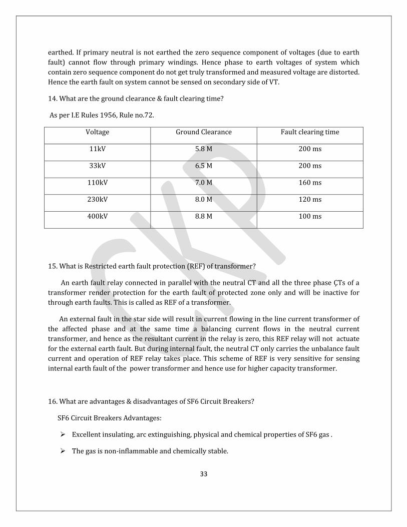
14. What are the ground clearance & fault clearing time?
As per I.E Rules 1956, Rule no.72.
Voltage Ground Clearance Fault clearing time
11kV 5.8 M 200 ms
33kV 6.5 M 200 ms
110kV 7.0 M 160 ms
230kV 8.0 M 120 ms
400kV 8.8 M 100 ms
15. What is Restricted earth fault protection (REF) of transformer?
An earth fault relay connected in parallel with the neutral CT and all the three phase ÇTs of a
transformer render protection for the earth fault of protected zone only and will be inactive for
through earth faults. This is called as REF of a transformer.
An external fault in the star side will result in current flowing in the line current transformer of
the affected phase and at the same time a balancing current flows in the neutral current
transformer, and hence as the resultant current in the relay is zero, this REF relay will not actuate
for the external earth fault. But during internal fault, the neutral CT only carries the unbalance fault
current and operation of REF relay takes place. This scheme of REF is very sensitive for sensing
internal earth fault of the power transformer and hence use for higher capacity transformer.
16. What are advantages & disadvantages of SF6 Circuit Breakers?
SF6 Circuit Breakers Advantages:
Excellent insulating, arc extinguishing, physical and chemical properties of SF6 gas .
The gas is non-inflammable and chemically stable.

34
The decomposition products are non-explosive i.e, there is no risk of fire or explosion.
Electrical clearances are very much reduced because of high dielectric strength of SF6.
Outdoor EHV SF6 circuit breaker has less number of interrupters per pole in comparison to
the air-blast circuit breaker and minimum oil breaker.
Outdoor SF6 circuit breaker is simple, comparatively cheaper in cost, maintenance free and
compactIts performance is not affected due to variation in atmospheric conditions.
It gives noiseless operation ,it does not make sound like air-blast circuit breaker during
operation.
No frequent contact replacement-arcing time is small owing to outstanding arc quenching
properties of SF6 and therefore contact erosion is less. Hence contacts do not suffer
oxidation,hence, no reduction in dielectric strength of SF6 since no carbon particle is
formed during the arcing.
Require minimum maintenance.
The breaker may require maintenance once in four to ten years. The sealed construction avoids the contamination by moisture, dust, sand etc. No costly compressed air system is required as in the case of air blast circuit breaker. Same gas is re-circulated into the circuit thereby reducing the requirement of SF6 gas. No over voltage problem. The arc is extinguished at natural current zero without the current chopping and associated over-voltages originating across the circuit breaker terminals.The SF6 gas circuit breaker can perform various duties like clearing short line faults, opening unloaded transmission lines, capacitor switching, transformer reactor switching etc without any problem. Ample overload margin. For the same size of the conductors the current carrying capacity of the SF6 circuit breakers is about 1.5 times that of the air blast circuit breakers because superior heat transfer capability of the SF6 gas. Disadvantages:
Imperfect joints leading to leakage of the SF6 gas. Continuous monitoring devices are requiredSF6
gas is suffocating to some extent. In case of leakage in the breaker tank SF6 gas being heavier than
the air settles in the surroundings and may lead to suffocation of the operating personnel. However
it is not poisonous. Arced SF6 gas is poisonous and should not be inhaled. The internal parts need
thorough cleaning during periodic maintenance under clean and dry environment. Dust of Teflon
and sulphides should be removed. Special facilities are required for transportation of gas, transfer
of gas an maintenance of quality of the gas. The deterioration of quality of gas affects the
performance and hence reliability of the SF6 circuit breaker.
17.What is insulation coordination?
Any line has lot of equipments associated, like transformers , alternators, etc.

35
If a line is designed to deliver power at 400kV, the insulation of the equipments associated would
be deigned keeping that level in mind with all possible overvoltage situations,viz,
-Switching overvoltages
-Lightning strikes
-Temporary overvoltages.
Insulation coordination is thus an art to decide the insulation level of the equipments keeping in
mind of all these parameters.
A very rough illustration :-
A 230 kV/110 kV transformer is designed with a BIL of say, 900 kV. It means that it will be able to
withstand an O/V of 900 kV, 1.2/50 micro sec wave.
Hence, the SA should bypass a surge of say 700* kV and above (assuming about 20% safety margin).
So if a surge of less than 700 kV is incident, it will be allowed to reach the transformer but anything
above will be bypassed and only the voltage across the SA, around 700 kV , will be allowed to be
applied to the transformer. Thus the transformer is protected with a SA of proper rating and the SA
is also not damaged. This can further be extended to CBs, bus bars etc in a similar manner.
அரட, டிரன்ஸ்தரர்ர் BIL ிட, SA ின் ஷத தரஸ் வனல் அறகரகத்
ரன் இனக்கும். ணஶ,டிரன்ஸ்தரர்ர், அட ரங்கறக் கூடி அபிஷண ரங்க ஶண்டி னரம்.
18.What is Trickle charging of a battery?
Trickle charging or floating charging of battery is one and the same.
It's roughly one milli ampere per Ampere hour of the battery capacity.
For eg: If the battery capacity is 120 Ahr, the trickle/floating charging current shall be 120 mA plus
the SS DC Panel load current used for indication ckt,etc.
This trickle charging is just to maintain it's sp.gr.and cell voltage.If,the above thumb rule of 1
mA/1Ahr is not sufficient, we can increase the charging current.
If the sp.gr.of the cells vary in wider range,quick charging is to be carried out in SS
maintenance வரடர்.
The quick charging current may be one fourth of the full charging current initially, that's 3 Amps for 120 Ahr battery, and gradually increased according to the cell temperature.
36
19. Why is trickle charging required?
Connection of multiple cells is a battery set. And the cells' internal resistance and the connecting resistance and the circuit resistance draws some minimal current and that gradually reduces sp.gr value of the weaker cells.
To compensate self discharging in the cells and circuit and also to feed the continuous load of
the DC panel & DC leakage etc.
20. "வ கண்டரி ஷ டு ர்த் தரல்ட் கண்ட்ஷட இந் tertiary வடல்டர ஷண்டிங்கறஶனஶ சுற்நறிட்டு ிடுட."
இட வ்ரறு டக்கறநட ன்று இன்னும் வபிரக ிபக்க னடினேர??
னற் றக்கறஶநன் இஷநனபரல். று இனப்தின்,வதரிஶரர்கள் றனத்ட்டும்.
In a three-phase system the third harmonic currents of all three phases are in phase with each
other because they are zero-sequence currents. In the Y-Y connection, the only path for third
harmonic current is through the neutral. In the ∆ -Y connection, however, the third harmonic
currents, being equal in amplitude and in phase with each other, are able to circulate around the
path formed by the ∆ connected winding. The same thing is true for the other zero-sequence
harmonics.
21. Why do we ground the wye windings of transformers and generators?
Greater safety.
Freedom from excessive system overvoltages that can occur on ungrounded systems during
arcing,resonant or near-resonant ground faults.
Easier detection and location of ground faults when they do occur.
Whenever there is short circuit a heavy rush of charge flows through the circuit which can
damage the circuit and the appliance connected to it. So if there is proper grounding,all the
surplus current can take the route to earth and our devices can be protected.
Whenever there is a problem of voltage dip in the network ,a good and healthy grounding
can help to increase the voltage level and here earth acts as having infinite potential.
Current flows back to household from earth so as to maintain a proper potential difference.

37
22. What is the difference between restricted earth fault and standby earth fault protection in
transformer and how it is used in the power System?
Prominent earth fault protections are Restricted earth fault, standby earth fault, sensitive
earth fault protection. In a restricted earth fault protection, the CTs are connected in
During earth fault, the phase lead is earthed & so fault current flows depending on the
potential (voltage level) at which fault has occured. Usually, ~80% of the winding is protected, the
remaining 20% of the winding which is close to the Neutral is not. Now if a fault occurs at such a
location where voltage to ground is less, the chances of such earth fault getting detected is very less,
and thus the fault may aggravate. The REF scheme is a solution to that. When there is a earth fault
within the range of the 4 CTs, the relay senses and trips.
Sensitive earth fault is given by providing a core balance CT (CBCT) to the feeder cable.
CBCT senses on the principle of Ir + Iy + Ib = 0. Any residual current becomes unbalance and is
sensed by the CBCT, and if the CBCT secondary current is more than relay set value, it trips.
The standby earth fault is just like a normal earth fault which acts on a CT connected at star
(Y) point. it is used like a backup protection, usually provided to trip the HT breaker of the
transformer.
23. What is Basic Insulation Level of electrical equipment?
When lightning impulse over voltage appears in the system, it is discharged through Surge
Arresters(SAs) before the equipments of the system get damaged. Hence, the insulation of such
equipment must be designed to withstand a certain minimum voltage before the lightning impulse
over voltage gets discharged through SAs. Therefore, operating voltage level of the SAs must be
lower than the said minimum voltage withstand level of the equipment. This minimum voltage
rating is defined as BIL or basic insulation level of electrical equipment.
The BIL is not calculated but is stated by standards.
BIL for 11 kV: 75 kV.
For 33 kV:170 kV.
For 110 kV:550 /650 kV.
For 230 kV:900/1050 kV
For 230 kV:900/1050 kV.
38
24. What is current chopping?
When low inductive currents, such as magnetiing current of transformer, shunt reactors
are interrupted by VCB , there is rapid deionization of contact space and may cause the current to
be interrupted before it's nautral current zero which causes current chopping. (chopping the
continious current flow into bits)
The transient voltage having high rate of rise of restriking voltage( RRRV) appears across
the contacts, unless the arc restrikes. If the arc restrikes, further chopping or several chopings of
current may occur before the arcing is finally interrupted.
அரட, றன்ஏட்டத்ஷ, அன் இற்ஷகரண கண்ட் ஜஶீர கறர றங்கறற்கு னன்தரகஶ, எஶ அடிரக வட்டி ிட்டு ிட னடிரல்,RRRV கரரக,
கண்ஷட டண்டு டண்டரக வட்டி ட்டன் ரப்ஸ் ஶதரடுட ரன் கண்ட் ஶ ரப்திங்.
இந் றகழ்வு (இற்ஷக கண்ட் ஜஶீரவுக்கு னன்ஶத, கண்ஷட ீக்குட) ,
ஆில் ர்குட் திஶக்கரில் ட்டும் ரன் இனக்கரட. வணணில், இறல்,
ஆர்க்ஷக அஷக்கும் க்ற, ஃதரல்ட் கண்டின் அபஷச் ரர்ந்றனப்தரல் ரீஸ்டிஷக்கறங்கறற்கும், அன் அடுத் ிஷபரண கண்ட் ஶ ரப்திங்கறற்கும் ரய்ப்தில்னரல் ஶதரய் ிடுகறநட. ஆணரல், ற்ந திஶக்கர்கபில்,ஆர்க்ஷக அஷக்கும் க்ற றந்ரணட ன்தரல், அற்நறல் ரீஸ்டிஷக்கறங் ற்தட்டு, அணரல், கண்ட் ஶ ரப்திங்கும் உண்டரகற ிடுகறநட. அடவும்,
ஶக்கும் திஶக்கரில், றன்கடத்ர ன்ஷ ீள் க்ற றகவும் அறகம் ன்தரல், ி றதிில் கண்ட் ஶ ரப்திங் வகு தி றத்ம்.
25. What is differential relay?
The differential relay works on the principle of comparison between the phase angle and
magnitude of two or more similar electrical quantities. This relay checks the difference in
magnitude and phase between the incoming and outgoing quantities on real time basis and if the
difference between these two quantities exceeds the pre set value then the relay will operate and
isolate the unit from the faulty zone. Differential relay (ANSI code 87) is the most important and
widely used for the protection of Transformers,Generator-Transformer unit, Bus Bars, Feeders and
heavy Motors etc in electrical power system.

39
What goes in must come out.
இட ரன் டிஃவதரின்றல் ரிஶனின் ரத்தரிம்.
அரட, ஶதரணர ந்டத் ரன் ஆனும். ந்ர ஶதரய்த் ரன் ஆனும்.
ஶதரட்டட ரன் கறஷடக்கும். கறஷடக்கறநட ஶதரட்டட ரன்.
Rule of KARMA. So, diffl relay is based on தகரன் கறனஷ்ன் தகத் கலஷ.
26. What is meant by capacitive current breaking in a circuit breaker?
Circuit breakers operates at current zero, i.e. in a sine wave current goes to zero value in
every half cycle, and at that point circuit breaker opens to clear the fault. You can see the current
zero in below figure.
Now, in case of resestive load, voltage and current are in phase, i.e. at current zero voltage
is also zero. So, while opening the contacts in case of resistive load, only system voltage appears
across circuit breaker’s contact, and this voltage is not sufficient to create the arc again. And hence,
resistive loads are easy to interrupt.
But, in case of capacitive load (like capacitor banks), voltage and current are not in phase
with each other. And hence, voltage will be of maximum value at current zero, and this could result
in voltage of value 2.0 pu across the breaker contacts while interrupting the fault current.
27. How does a vacuum circuit breaker(VCB) work?
A VCB consists of a vacuum chamber into which two electrical contacts are inserted with
the bellows on the bottom side of the contacts to physically move( with out disturbing the vacuum
inside the interrupter) which separates the electrical connection between the two contacts.
The vacuum inside the interrupter bottle has excellent insulation qualities causing quick
arc quenching with minimal mechanical movement of the moving contact due to which the
interrupter bottle is very compact.
Any attempt to open an electrical circuit will form arcing between the contacts, which is
imperative that the circuit breaker has to extinguish this arc quickly,or otherwise the arc will eat
away the contacts resulting overheating leading to a deadly arc blast.

40
28. What are type of relays based on functional categories?
1. Auxiliary relay.
2. Regulating relay.
3. Programming relay.
4. Monitoring relay.
5. Protective relay.
29. Why 80 % setting is adopted for zone 1 setting of distance relay?
If 100% of line impedance is adopted for zone 1 setting, then it may over reach due to DC
offset and CVT transient responses resulting loss of selectivity which could not be tolerated in EHV
lines.Hence 80% setting is adopted.
31. What is Power Swing?
In the synchronised, integrated grid, all the rotor angles are constant under steady state
operation. During sudden and large changes of power in the system (due to outage of a major tie
line) , the rotor angles under go oscillations till the system reaches a new stable state. This
phenomenon is called as power swing.
டைற்றுக்கக்கரண றன் ஆக்கறகள் என்நரக ஶஷன வ ய்ட வகரண்டினக்கும் ஶதரட, றடீவன்று ற்தடும் றன் தரஷ ிப்தரல் ற்தடும் தர் ஊ னரட்டம்.
ற்ஶதரட றகத்றல் டக்கும் அ றல் உள்கட் றத் கரநரல் ற்தட்டுள்ப ஊ () னரட்டம் ஶதரன.
அந் வனக்டிரிகல் தர் ஸ்ிங்கரட, றன வரடிகபில் வ ட்டில் ஆிடும். இந் வதரனறட்டிக்கல் தர் ஸ்ிங் ப்ஶதர, ப்தடி வ ட்டினரகுஶர????
31. Why the secondary of a transformer is to be Opened first?
The load of the transformer has to be first taken off so that the primary breaker has to
interrupt only the no-load current of the transformer.

41
32. Why do high voltages develop across the leads of an open CT secondary?
(1).The primary current of the CT is not depending on the secondary current of the CT alike in
conventional transformers.
So, the primary ampere turns will be independent of it's secondary ampere turns in open condition.
(2).In very simple terms, the CT has to be considered as an amp-turns device. The primary is
connected in series with the load, but has no appreciable impact on secondary current. That load
current, times the number of turns gives the amp-turns into the core. Now those amp-turns have to
come out of the core, that's what the secondary is for. With the secondary shorted, there's a really
easy place for those amp-turns to go, around that very low impedance loop.
(3). As the CT primary is connected in series with the line, it can be viewed as a constant current
source. When there is a normal burden connected to the secondary of the CT, the current that flows
through the ideal transformer is the primary current minus the excitation current, which flows
through the magnetizing branch. When the burden connected to the secondary is removed, all of
the primary current is "forced" through the magnetizing branch, which is a relatively high
impedance. So there will be high current through a high impedance, which develops a high voltage
across the magnetizing branch, which is in parallel with the ideal transformer and, in turn, the
secondary winding of the CT.
In conventional transformer, if there is load in the secondary, the secondary mmf (N2 I2) and the
primary mmf (N1 I1) cancels each other and in order to maintain the core flux constant.
But in the current transformer, if there is small load in the secondary, the secondary mmf and
primary mmf cancels each other and there is a very small net mmf in the core and since the
secondary does not draw any current but rather the current is forced into the secondary circuit.
If the secondary is shorted, it means there is no load at the ct secy. Then also there will not be
unequal mmf which will not disturb the core balance. But if the CT is not shorted, the primary
ampere turns could not be cancelled by it's secondary ampere turn resulting huge voltage in the CT
secondary.
சுனங்கச் வ ரல்னற ிபங்க ஷக்கனுறன்ணர, றடிின் திஷரி கண்ஷட அபக்கத்ரன் அன் வ கன்டரி கண்ட். இட, அஷ திறதனறப்தட.
ஆணரல், அட(திஷரி), இஷச் ரர்ந்ட அல்ன, ர டிரன்ஸ்தரர்ர் ஶதரன. ணஶ, சுந்றரண திஷரி ஆம்திர் டர்ன்ஷண ஶகன் ல் வ ய்,
வ கண்டரிஷ ர்குட்டில்/ரர்ட்டில் ஷக்க ஶண்டினேள்பட. இல்ஷனஶல்,ஆம்திர் டர்ன் ஶதனன்ஸ் குஷனந்ட ஶதரய், வ கண்டரிில் அறகப்தடிரண ஶரல்ட்ஶடஜ் உண்டரகற, ர்குட்ஷட ரித்டிடும், றடி
42
வடித்டிடும். அறல் உண்டரகும் ஶரல்ட்ஶடஜ், திஷரி கண்டின் அபஷனேம், றடி ஶறஶரஷனேம் வதரறுத்ட.
33. What is transferred earth potential?
Transferred earth potential
(TEP) refers to the voltage-to-earth of grounding systems that will appear on conductors as a result
of the source system grounding electrode being above normal earth potential, developed by ground
fault currents returning to their source through earth.
A common eg: A ground fault of a conductor, supplying a substation transformer primary, to the
station ground grid that is used for grounding of the transformer secondary neutral. If this
grounding grid is not connected to the high-voltage source system ground, there can be a significant
voltage rise above earth as the fault current flows into the earth. Low voltage conductors leaving
the area where the ground or the grounding electrode voltage has been affected will have the
voltage added to their normal line-to-ground voltage which may exceed the insulating rating of the
conductors or the equipment to which they are connected.
TEP occurs most frequently if the grounding of a facility is less than adequate due to seasonal
variations in earth resistivity due summer which can lead to thousands of ohms per centimeter
earth resistivity resulting, even small current flowing to earth can cause elevated potentials within
the facility.
If facility grounding is poor and the grounding of utility transformers is also weak, then the effects
of TEP will be worse.
Wye-to-wye supplied facilities may be more prone to develop TEP problems.
34. When zero sequence current flows?
All faults that produce ground current create a zero sequence potential difference that
causes zero sequence or ground currents to flow.
During faults, the zero sequence current can represent the tightness of the neutral to
ground.
In a solidly grounded system, there usually is a lot of available fault current for ground
faults due to the thevenin impedance of the zero component being small and the positive and
negative sequence thevenin impedences being small by design to prevent large voltage drops.

43
In an ungrounded system, the thevenin zero sequence impedance is infinite (not exactly
due to capacitive grounding in the system) and the neutral point will separate from the ground
easily.
High resistance grounded systems provide the best of both worlds by providing enough
ground fault current to make it easy to locate the fault while at the same time reducing the
magnitude of the ground fault currents to protect equipment and personal and preventing over
voltages due to line-to-neutral voltages increasing to line-line voltages.
35. Any specific point to be noted in Dissolved gas analysis (DGA)?
DGA being done only based on individual gas content.
It has to be analysed based on the ratios of the different gases present in the oil which can often
make a fair guess as to what kind of fault we are dealing with - arcing, high temperature metal, low
temperature metal, insulation degradation due to overloading, and so on.
DGA works best when the oil is periodically sampled, allowing trends to be observed over a period
of time, rather than as a snapshot after a fault, but it can still be useful post-event.
36. Define the rate of rise of restriking voltage (RRRV) and what are the factors on which it depend?
RRRV : Ratio of peak value of restriking voltage to the time taken to reach the peak value.
If the rate of rise of dielectric strength of the arc quenching medium developed in between the
contacts is lower than the RRRV, the arc will not be extinguished.
RRRV depends on inductance and capacitance of the system and switching conditions.
37. What is the main reason for transformer fire?
TANK RUPTURE
Without tank rupture, there will be no fire as without oxygen fire cannot start.
So, periodic painting of all transformers, oil leakage arresting are very much essentially to
be carried out like DGA to avoid transformer fire.
38. If arcing noise observed in the OLTC chamber, what to do?
Check whether at this tap the regulating winding is floating.

44
If no tie in resistor is provided, it can happen. Conduct a DGA of main tank oil and LTC
chamber oil.
39. What are the reasons for voltage spikes?
Voltage spikes gets generated due to :
Lightning.
switching of inductive load.
Electromagnetic pulses.
40. What is restriking voltage?
The transient peak voltage that appears across the circuit breaker at the instant of arc
extinction is called the restriking voltage.
41. What is an Arc ?
During opening of current carrying contacts in a circuit breaker the medium in between
opening contacts become highly ionized through which the interrupting current gets low resistive
path and continues to flow through this path even the contacts are physically separated. During the
flowing of current from one contact to other the path becomes so heated that it glows which is
called arc.
42. Enumerate the Recovery Rate Theory of arc extinction.
The rate at which the dielectric strength of the arc quenching medium get recovered is
compared with the rate at which the restriking voltage across the contacts rises.
If the rate of rising of re-striking voltage (RRRV) is rapid than the dielectric strength, then
the space breaks down and arc persists. Since arc consist of column of ionized gases, the ions &
electrons are to be removed from the gap immediately after the current zero crossing so as to
extinguish the arc. They can be removed either by recombining the ions and electrons with neutral
molecules or by sweeping away the ions in between the gap by the arc quenching medium with a
rate faster than the rate of ionization, only then the arc get interrupted.
அரட, என்று, அணிகஷபச் ஶ ர்க்கனும் அல்னட அப்னநப்தடுத்னும், that's
all. னர & ஆர்டர் விண்வடின் தண்டஷப் ஶதரனஶ. �

45
43. Define the rate of rise of restriking voltage (RRRV) and what are the factors on which it depend?
RRRV : Ratio of peak value of restriking voltage to the time taken to reach the peak value.
If the rate of rise of dielectric strength of the arc quenching medium developed in between the
contacts is lower than the RRRV, the arc will not be extinguished.
RRRV depends on inductance and capacitance of the system and switching conditions.
44. What is Arc Quenching??
The process of cooling, stretching, or spreading out the arc within the spark gap so as to
prevent the previously ionized path from reigniting on reapplication of voltage. It is mostly applied
to AC power arcs and RF spark gaps, and also to high voltage DC switching. Quenching a high
voltage arc needs the arc current passing through zero for a period of time. Which can be done
using the normally occurring AC current zeros and also during brief current zeros.
45. What is an Arc in a circuit breaker?
During opening of current carrying contacts in a circuit breaker, the medium in between the
contacts become highly ionized through which the interrupting current gets low resistive path and
continues to flow through this path even the contacts are physically separated.
During the flowing of current through a non conducting medium in between the contacts, the
path becomes heated up and glow establishing an arc.
கம்திில் ஶதரணரல் கண்ட். அடஶ, கம்திஶ இல்னரல் ஶதரணரல் அட,
ஆர்க்.
46. Which type of gas is SF6?
It's electro negative gas with low gaseous viscosity and higher molecular weight. The highly
electro negative property of this gas helps in arc extinction. It gets decomposed to SF4 and SF2
during arc quenching. SF6 gas is imported in liquid form in cylinders.
Demerits:

46
Sealing problems of the gas and ingress of moisture in the gas system which is dangerous.
47. How the ground fault on the LV side of a delta/star transformer will be reflected on the HV side?
For a line to ground fault on the secondary side of a delta/star transformer 1.00/unit, there
will be a current of 0.58/unit in two of the 3 phases on the primary side.
That's why it's very difficult to provide adequate through - fault protection for the above trfr
from only on the primary side. So, any ground fault protection on the trfr py side will not see secy
side ground fault.
48. What are to be noticed on maintenance point of view in respect of VRLA battery?
Internal ohmic readings to be taken quarterly for VRLA battery along with individual cell
voltage & temperature reading and any adverse trend to be checked.
49.How do CTs get Saturated?
During steady state conditions, CT secondary current does not exceed it's rated
value.But,it will exceed when fault occurs and CTs remain normal if the current is within it's ALF.
ALF designation letters are C,K,T,H & L. C & K are protection class CTs with negligible leakage flux.
Class K is same as that of C class CTs except that it's knee point voltage must be at least 70 % of the
secondary voltage rating. Eg:1A,100 VA CT, Voltage :100 V. So, knee voltage should be greater than
70 V. T class CTs are non negligible leakage flux. H & L are old ANSI std CTs(1954 CTs). Hence, if the
CT secondary current exceed it's ALF, increase in CTs secondary voltage can happen which increase
it's core flux, creating a disproportionate increase in magnetizing current saturating the CT core.
50. How to prevent frequent failure of capacitor units in the capacitor banks?
The failure of capacitor is mainly due to surge voltages during switching due to restrikes. Station
class Surge arrester on capacitor bank is recommended to suppress the high switching surges.
51. What is the short circuit withstand duration for transformers?
For smaller transformers of below 0.5 MVA capacity :1 sec.
For power transformers :2 seconds.

47
For transformers of capacity above 300 MVA:5 secs.
52. What is meant by capacitive current breaking in a circuit breaker?
Circuit breakers operates at current zero, i.e. in a sine wave current goes to zero value in
every half cycle, and at that point circuit breaker opens to clear the fault. You can see the current
zero in below figure. Now, in case of resestive load, voltage and current are in phase, i.e. at current
zero voltage is also zero. So, while opening the contacts in case of resistive load, only system voltage
appears across circuit breaker’s contact, and this voltage is not sufficient to create the arc again.
And hence, resistive loads are easy to interrupt.
But, in case of capacitive load (like capacitor banks), voltage and current are not in phase
with each other. And hence, voltage will be of maximum value at current zero, and this could result
in voltage of value 2.0 pu across the breaker contacts while interrupting the fault current.
53. What is the significance of CT polarity?
When CTs instantaneous primary current flow through it's H1 terminal, it's secondary
instantaneous current will leave out through S1. This determines the relative polarity for
directionally sensitive devices connected to it's secondary terminals.
54. Which will be the worst fault current?
Assymetrical, having a decaying DC component. When DC offset is at maximum, the CT flux
increases about 1+X/R times the flux. The decaying DC offset will saturate it's iron core and
reproduction of the primary current will be distorted.
55. How to find any arcing inside a switch gear at an early stage without opening it?
Have an AM Radio set between two stations (not FM). Extend it's antenna and get it near
the switch gear. If a cracking sound is heard, it's more likely due to sparking inside the brkr.
56. What are the limitations of differential relay in transformer protection?
It is not sensitive enough for single phase to ground faults close to grounding point in
solidly grounded transformers. Challanging for turn to turn fault.

48
This fault will cause high current only in the shorted portion of the wdg ( not in line
currents insufficient for actuation of diffl relay) which causes arcing locally, releasing combustiable
gas resulting actuation of Bucholz relay.
57. How is arc extinguished in circuit breakers?
A ckt brkr attempts to extinguish the arc at a current zero crossing,after the contacts opening. When the arc is extinguished, the system imposes a TRV (Transient Recovery Voltage) across the contacts.
If RRRV (Rate of rise of recovery voltage) and hence TRV across the brkr contacts is
lower than the BDV of the arc quenching medium , the arc will be extinguished. Where as, if TRV is
higher than the BDV of the quenching medium due to system passive elements, the arc will restrike
and the breaker must try again for extinguishing the arc at another current zero crossing. After
initial time of thermal energy balance in between the contacts gap, the dielectric *race* takes place
and got settled according to system conditions.
58. What is fault level?
The maximum short circuit power that could occur in a particular bus is called the fault(3
phase fault) level of that particular bus.
59. What are the type of faults?
Phase to earth .
Phase to Phase.
Three phase fault.
Three phase to earth fault(rare).
Number of faults in the system occur in the same order.
75% of faults are only earth faults.
60. What is the significance of fault level?
To install the breakers with breaking capacity over and above the fault level.

49
To design and provide earthing system of the substation.
61. What are type of feeders?
Radial feeder: Feeds with only one source from one end.
Grid feeder /Ring main: Fed by different sources from both ends.
62. What are the protections employed for radial feeders?
Over current protection with time delay & instantaneous features.
Earth fault protection with time delay & inst. feature.
No earth fault relay is employed on the LV side of the transformers in our substations.
63. What are the protection used for grid feeders?
Distance protection.
Directional over current & earth fault protection.
64. What are the protections used for transformer?
Bucholtz protection.
Winding temperature Trip.(90 deg. C)
Pressure relief valve trip(0.41 kg/sq. Cm.
OLTC Surge relay trip.
Differential/Merz price/Circulating current protection.
65. How to calculate the absolute impedance of a transformer?
Imp. of a Tr. =(kV SQUARE / Capacity of Tr. in MVA)*P.U.IMPEDANCE.
For eg:(110*110/10 MVA)0.1(P.U.Z)=121 OHMS
50
1. In a Solar plants, why the feeding /pooling stations supply is 33 kv to 110/220kv (maximum)
instead of 11kv in case of Solar plants.? Is there any possibility of cascade effects in the grid? Or
deteriorating the supply / system parameters? Any cost consumption / space on 33kv system.
Stability point of view,either WEG or Solar plants are useless in case of dynamic
response,VAR support and inertia support.So,the question of voltage level in respect of stability
point regarding RE Plants does not arise.
Hence,the main criteria of voltage connectivity for pooling stations for RE shall be only the
maximum power transfer for which the optimum voltage will be 33 kV since we adopt max power
of 5 MW in 11 kV and 15 MW in 33 kV,naturally line loss will be lesser in 33 kV lines than 11 kV.
Hence, 33 kV pooling stations are preferred for RE plants.But I think there are also 11 kV grid
connected REs feeding distribution loads and connecting to the normal distribution substations, of
course not to the Pooling Stations.
2. Frequency இன் யறஸ்டரிஷக் வகரஞ் ம் தரர்ப்ஶதரர?
!!(யறஸ்டரின்ணர னரறு ரஶண?)!!
From the history of electrivillage(கறரத்ரஶண கறரத்ஷ எடக்கக் கூடரறல்ஷனர? அணரன!!!), it is learnt that various level of frequency
Viz,133.33,60,50,40,25,16.66 Hz were initially used and finally got setteled in two level of frequency
60 & 50 Hz.
இட ரன் ன்நறல்ஷன!! ந் அறர்வண்டம் தன் தடுத்ப் தட்டுள்பட,திநகு ,50 & 60 Hz ன்று இனிரக வ ட்டினரகறனேள்பட.
60 Cycles/ Sec ன்தறல் என அர்த்றனப்தினும் திரிட்டீஷ்கரர்கபின் னஷநக்கு வதரனத்ரக 50 Hz அஷந்ரகவும் வ ரல்னனரம்!
உனக ரடுகபில் வதனம்தரன்ஷரண தகுறகபில் 50 Hzம்(ங்கள் திரிட்டீஷ் ரம்ரஜ்த்றல் சூரிஶண ஷநறல்ஷன ன்னும் ீதரண்டி கட்ட வதரம்ன் ணம் உண்ஷரஶண??), அவரிக்கர,கணடர ஶதரன்ந றன ரடுகபில் ட்டும் 60 Hzம் ஜப்தரணில் ட்டும் இண்டு அறர்வண்கலஶ தன்தடுத்ப் தடுகறன்நண( Of course ணித்ணி தகுறகபில் ரன்). ஏஶக?

51
ஃதிரிவகரன் ற ன்நரல் ன்ணவன்று வகரஞ் ம் ரன்-வடக்ணிக்கனரக
தரர்ப்ஶதரர?
டி ற ன்ணிஷனஷ ரற்நறக் வகரள்பரல்,
தர றட்டிவ் ப்ஶதரடம் தர றட்டிரகவும், வகட்டிவ் ன்றும் வகட்டிரகஶ இனப்தரல் அற்கு இண்ட்னைஸ் தண்டம் க்ற இல்னரரல் ,ரர் ஆஃப்
கண்ட்மறல் டி ற (ரஸ் ஆல்ர டி ன்) ஶரற்றுப்ஶதரய், ற ன்ணிஷனஷ ரற்நறக்வகரள்லம் ன்ஷரல், இண்ட்னைஸ் தண்டம் இல்தரல் திதனரகற வஜித்ஷனேம்(றக்ஶகரனர வடஸ்னர) னன்ஶத வ ரல்னறக்கலஶநன். ( ட்டச் வ னரபர் ண்டு னனகன் ரறரி கட் ற ரறுதர்கலக்குத் ரன்அ றனறலும், அறகரத்றலும் ல்ன கரனவன்று!!!)
So, AC ன் றஷனப்தரட்டிஷண (தர றட்டிினறனந்ட வகட்டிிற்கு) என வ கண்டில் த்ஷண டஷ ரற்நறக் வகரள்கறநஶர அந் ண்ிக்ஷக ரன் ஃதிரிவகரன் ற!!
அல்னட,என வ கண்டில் ட்டும் இந் ஶரஶணர குஶரஶட்டிக் டிரன்ஸ்வர்ஸ் ஷ னுமரய்டல் றன் கரந் அஷன(Monochromatic Transverse
Sinusoidal Electro Magnetic wave) தர றட்டிவ் ஷ டில் ட்டும் த்ஷண டஷ உச் ம் வரடுகறநஶர அட ரன் ஃதிரிவகரன் ற!!!
(ன ன்னும் வ ரல்னனரம்,னய்தம் ன்னும் வ ரல்னனரம்). ஏஶக?
ட தர் கறரிட் இப்ஶதரட இங்கற னம்
49.90 to 50.05 Hz ன்னும் இந் அறர்வண் ஶஞ்ஜ் ,ந் ஶஞ் றனறனந்ட ந் ிரகவல்னரம் ரநற ந்டள்பட ன்று தரர்ப்ஶதரர?
1.2.2000 ஷ IE Rules 1956 இன் அடிப்தஷடில் றன் கட்டஷப்தின்(Grid)
அறர்வண் இங்கு ல்ஷன 48.5 to 51.50 Hz ஆக இனந்ட ந்ட.
திநகு,1.2.2000 இல் 48.5 to 50.5 ன்தரக ரற்நப்தட்டட. அடுத்ட 1.4.2002
இனறனந்ட 49.0 to 50.5 ஆக ரற்நப் தட்டட.
52
3.5.2010 இனறனந்ட 49.5 to 50.2 ன்று உத்ிடப்தட்டட.இட ஷ ரிஶ!
அடிக்கடி கறரிட் திபரக் அவுட் ஆட இணரல் ரன் ன்று றனர் னடிவுக்கு ந்ணர். 30.7.'12 /2.00 AM அபில், ரர்த்ர்ன் கறரிட் திபரக் அவுட் ஆண ஶதரட இனந் அறர்வண் 50.20 Hz. யரர்ட் அட்டரக்,
ஷய B.Pஇல் ரன் னும் ன்நறல்ஷன, B.Pரர்னரக இனக்கும் ஶதரட கூட னரம்!
Grid collapse may occur due to sudden outage of generators and also tripping of critical
transmission elements resulting cascade trpping. Grid inertia (வ்பவு அடிச் ர ரங்கும் ன்னும் அபவு) கறரிட் அறர்வண் குஷநரக இனக்கும் ஶதரட வகரஞ் ம் கீ்கரகற கறரிட் வகரனரப்மரக ரய்ப்ன அறகம்.
இனந்ரலும், ஶனர ஃதிரிவகரன் ற ட்டுஶ றச் ம் ப்ஷப திபரக் அவுட்டிற்கு கரறல்ஷன!ஆணரல்,ணிரர் டஷநிணர் றஷந றன் றஷனங்கள் அஷத்றனந்ரலும், றஷந ரறனங்கள் றன் தற்நரக்குஷநில் ப்தடிஶர ட்டுத் டுரநற ரபித்ட ந்ரலும்,அற்ஷந தர் தர்ச்ஶ ஸ் தண் ஷப்தற்கரக றஇஆர் ற வகரண்டு ந் ஷநனகத் றட்டம் ரன் அடுத்ட 1.2.'12இனறனந்ட ஶலும் கறரிட் அறர்வண் இங்கு ல்ஷனஷ 49.7 to
50.2ஆக குறுக்கும் னற் ற.இந்றரின் அஷணத்ட ரறனங்கலம் இற்கு எப்னக் வகரண்ட ஶதரறலும்,ரம் ட்டும் 4000 வகரரட் தற்நரக்குஷநரல் சுரர் 8 ி ஶத்றற்குக் குஷநரல் ஶனரட் வட்டிங் தண்ிக் வகரண்டினந்ரல், அந் அறர்வண் இங்கு ல்ஷன குறுக்கும் உத்ிற்கு ீற ன்நத்றற்கு வ ல்ன ஶண்டிரிற்று. க்கநறஞர்கலக்கும்,
ீறதறகலக்கும் இற்ஷநவல்னரம் னரி ஷத்ட ஸ்ஶட ஆர்டர் ரங்கற ,தித்ணப்தட்டு ரரடி இறுற ஆஷ னம் றஷனில், றர்தரர ிரக(????) 30.7.'12 ற்றும் 31.7.'12 அடுத்டுத்ட இண்டு ரட்கள் ரர்த்ன் கறரிட் வகரனரப்மரகற ,தர் கறரிட் ஆட்கள் ஸ்ஶட ஆர்டஷ அற்கு கரரய்க் கரட்டி ரரட ட தக்கம் ஶரற்று 17.9.'12 இனறனந்ட 49.7 to
50.2 Hz அறர்வண் இங்க உத்ிஷண கஷடதிடிக்க ஶண்டிரிற்று.

53
ப்தடிினப்தினும், CERC ஆர்டஷ 7 ரங்கள் ள்பிப் ஶதரட்டஶரடல்னரல் அதரம் கட்ட ஶண்டி னஷ ிர்க்கவும் னடிந்ட!
இந் அறர்வண் குறுக்கு டடிக்ஷகிணரல் ஶனரட் வட்டிங் அறகரணடம், திநகு ந்டி தண்ரல்17.2.'14இனறனந்ட CERC 49.9.to 50.05 Hz
ன்று ஶலும் குறுக்கறடம் ,சூடு தட்ட னஷணரய் ,ஶறு றின்நற ,ரங்கள் ரய்னெடி வௌணிரக இனந்டவும்,இறுறரக க்கஷபத் ரன் றப் தடுத்றட.
இப்தடிரகத்ரஶண டந்ட அறர்வண் இங்கு ல்ஷன +/- 1.5(3 Hz) (48.5 to
51.5) இனறனந்ட வறும் 0.15 Hz ஆக சுனங்கறப் ஶதரகற, திஷஶட் வஜணஶட்டர்ஸ் வகரழுத் னரறு!
அப்ஶதரட தட்ட ண உஷபச் ல் ணறல் ன்றும் ீங்கர டு.
இம் ரறரி கஷக் வகரவ்ர ிறனஷநகபரல் றகவும் அறகம் தரறக்கப் தடுட கறரப்னந க்கள் ரன் ன்தஷ டபிக்கூட உர , ற அஷநிஶனஶ ர ர் கரனனம் னங்கறக் வகரண்டினக்கும், வ ரர்க்கத்ட னட்டரள்கள் அறகரத்றல் ஶகரஶனரச் றக் வகரண்டினக்கும் ஷ இந்ற ஷகள் னன் தரறக்கப் தடுறல் வ்ி னம் இல்ஷன!
3. Write a short note on Open access(O.A).
வடுஞ் ரஷனத் டஷந ஶதரட்டு (?) ஷத்டள்ப ரஷனகபில் அந்ந் ஶடரல் ஶகட்டுகபில் ரம் தம் கட்டிிட்டு அந் ரஷனகஷபப்
தன்தடுத்றக் வகரள்ட ஶதரன ,ட ரரிம் ஶதரட்டு ஷத்டள்ப டிரன்ஸ்றன் கட்டஷப்ஷத, ஸ்ஶடட்/வ ண்ட்ல் கறன்ஸ் அனுறத்டள்ப டிரன்ஸ்றன் ரர்ஜஸ்,வட்னைனறங் & ஆப்ஶட்டிங் ரர்ஜஸ் ஆகறற்ஷநக் கட்டிிட்டு ந்வரன றன்னுற்தத்ற கம்ஶதணிஶர,வயச்.டி. கன்ஸ்னைஶர தன்தடுத்றக் வகரள்ப ல்.டி. வ ண்டர் அனுறப்தட ரன் றநந்வபி டேஷவுரிஷ(Open Access).இட E.A.2003 Section 40 இன் தடி அனுறக்கப் தடுகறநட. ன்ண?!
54
ஶணல் ஷயஶமறல், ட வகறக்கஷப ஏட்டிண்டு ஶதரய் ரி கட்டிட்டு ,ஶடரல் ஶகட்ஷடத் ரண்டிப் ஶதரஶநரம்.
றன் ரம் கடத்(???) னனறஶனஶ அனுற ரங்கறக் வகரண்டு ரன் வஜணஶட்டர் கறரிடுக்குள் ணர்ஜறஷ வ லுத்டஶர,கன்சூர் திநர் அல்னட ன் றதிதி தஷ தன்தடுத்றக் வகரள்ஶர னடினேம்.
Open Access(OA) means admission of any consumer /generator to get or send power from any
where ,any time,any quantum(the last one allowed only in TN)
Why??? வணன்நரல், ட ரரிம் ஶகட்தரற்ந அரஷ!!அணரல்!).
அரட, ங்கறனந்டம்,ப்ஶதரடம்,ந் டிரன்ஸ்றன் னன் னெனனம்,
ந் அபவும் ,தர் ரங்கறணரஶனர,ிற்நரஶனர ம்தந்ப்தட்ட ஶனரட் வடஸ்தரட்ச் வ ண்டர் அனுறக்க ஶண்டும்(Of course with NOC from DISCOMs and
proper bilateral contracts and approved transmission charges and with compensation to loss)
ன்தட ரன் ஏப்தன் அமஸ்.
இட ,
Short Term Open Access (STOA).
Medium Term Open Access(MTOA),
Long Term Open Access(LTA)
ன்று னென்று ஷகரக அனுறக்கப் தடுகறன்நண.
STOA : For a perood upto one month at a time and allowed for a maximum period of 3 months.
னென்று ரட்கலக்கு னன்ன ிண்ப்திக்க ஶண்டும்.CERC Regulation தடி குஷநந் தட் அபவு 1.00 MW,but TNERC has reduced the quantum less than one MW
which is also a revenue killing aspect to TANGEDCO.
Transmission charge :Rs.2903/MW/DAY(12.10 Paise/Unit).Wheeling charge:18.87 Paise/Unit
totaling 31 paise/unit. & for Wind 12.39 paise/unit.
Scheduling charge:Rs.160 per day.

55
System operation charge:Rs.1.41/MW/Hour subject to a ceiling of Rs.500.(Only 40% of the above
for RE).
MTOA: Allowed for a period from 3 months to 12 years but not exceeding 3 years at a time.
LTA: For a period of more than 12 years upto 25 years.
E.A.2003இல் ந்வுடஶணஶ னந்றக் வகரண்டு 2005னறஶ O.A.Regulation ஶதரட்டு ட ரரித்றன் னரணத்ஷக் குஷநத்ஶரடல்னரல்,
இத்ஷண னடம் கறத்டம் Intrastate ABT Regulations ஶதரட்டு னஷநப் தடுத்ரரல் ஷ்டஷடந்ட வகரண்டினந்ஶரம்!
வகரண்டினக்கறஶநரம்!
வகரண்டினப்ஶதரம்!
(ிஷணத் வரஷக,இனக்கக் குநறப்ன ட்டுல்ன!ரரிம் வ ய் ிஷணகபின் வரகுப்ன!!).
இடஷ,HT கன்ஸ்னைனக்கு ட்டுஶ அனுறக்கப்தட்டு ந் ஏப்தன் அமஸ் வகுஶனன் அன்ணிில், வ ப்தஶன் ஆஃப் ஶகரிர் & கண்வடண்ட் னும் என ஏட்ஷடஷ(Amendment) றன் ட்டத்றல் ஶதரட்டு ரரிங்கஷப கரர்ப்தஶட் கம்ஶதணிகள் சுனட்டிக் வகரண்டு ஶதரக ஜனொரக ற்தரடுகள் டக்கறன்நண.
ட வட்எர்க்கறல் ஶகரிர் ட?
ட கண்ட் கம்தி!
சும்ர அந்த்றல் வரங்குல்ன!கரனங்கரனரய்,ட றன் வதரநறஞர்கலம்,வரறனரபர்கலம் வதனம்தரடுதட்டு உனரக்கற றன் கட்டஷப்ன!!
CONTENT ட?
அந்க் கம்திில் ஶதரகும் கண்ட்!
அரட, Separation of Carrier & Content ன்தட

56
உடஷனனேம் உிஷனேம் திரிப்தட ஶதரன்நட ; னேடினறட்டிகஷப வகரஷன வ ய்ற்கு எப்தரணட.
ற்கணஶ,உழுத் இஷப்னகலக்கு றநந் வபி டேஷவுரிஷ ந்ட ரரித்றற்கு ஷ்டம் உண்டரக்கறரிற்று.
ற்ஶதரட,இந் அவண்ட்வண்ட் னெனம் LT industrial & commercial consumersனேம் கரர்ப்தஶட்டுகலக்கு ரஷ ரர்த்டிட்டு,ரம் குடிஷ ,
ி ர,வடரவரஸ்டிக் ஶதரன்று வதத் னரதம் க்கூடி றன் இஷப்னகபின் னரணத்ஷ ஷத்டக் வகரண்டு என னட் ம் ஶகரடி கடஷண என றன ரங்கபிஶனஶ அஷடத்டிடனரம்!!!!���
ஶத ரல்,அம்ஶதத்கரர் ஶதரட்ட அ றனஷப்ஷத,*For the Corporates,of the
Corporates,by the Corporates,to the Corporates* ன்று ரற்நறிட்டுப் ஶதரகனரம்.�
4. What kind of oil is used in transformers?
The chemical name of transformer oil is Hydro treated Light Naphthenic /pharafanic oil and
commonly known as transformer oil/ mineral insulating oil (I.S.335),obtained by fractional
distillation and subsequent treatment of crude petroleum.
Transformer oil helps as liquid insulation and also as coolant , dissipates heat inside the
transformer. Also,this oil serves to preserve the core and winding as these are fully immersed
inside oil and prevents direct contact of atmospheric oxygen with cellulose made paper insulation
of winding, which is susceptible to oxidation.
There are two types of oil used in transformer:
1. Paraffin based transformer oil (Used in India): Paraffin based oil is used in India, because of
it’s easy availability and lower oxidation rate.
But it has high pour point due to the wax content but not of much concern due to prevailing high
temperature in India. But sludge formed in this oil is insoluble and obstruct the transformer cooling
system.
2. Naphtha based transformer oil:
Naphtha oil is more easily oxidized than Paraffin oil whereas it's oxidation product(sludge)
is more soluble than Paraffin oil and hence not precipitated in the bottom of the transformer

57
and hence does not disturb the trfr cooling system.
Properties of transformer oil as per IS 335:
(a)Electrical Parameters :Dielectric Strength(Minimum 50 kV).
Specific Resistance( 1500X10 power12 ohm.cm)
Dielectric Dissipation Factor(tan delta less than 0.01).
(b)Chemical Parameter :
Water Content(max 30 ppm)
Acidity less than 0.03 mg KOH/gm
Physical Parameters : Inter Facial Tension(more than 40 dynes/cm). Viscosity(less than 16.5),
Flash Point of more than 300 deg C and Pour Point-30 degC.
க்கு த் ஏட்டம் ரறரி டிரன்ஸ்தரர்க்கு ஆில் ர்குஶனன்.
ரம் திபட் வடஸ்ட் எழுங்கர தண்ிக்கனன்ணரலும் டிரன்ஸ்தரர்க்கு ஆில், DGA வடஸ்ட் தரீிரடிக்கனர தண்ிக்கனும்.இல்ஷனன்ணர,
டிரன்ஸ்தரர்ர் ட்டுறல்ஷன,ம் உடம்னம் ஶ ர்த்ட வகட்டுப் ஶதரகும்.�
5. Define Hysteresis loss in transformer.
Hysteresis ன்தற்கு "deficiency" or "lagging behind" ன்தட வதரடரண அர்த்ம். Hysteresis is a dynamic lag between an input and an output that disappears if the input is removed.
When an external magnetic field is crossed by a ferromagnetic material such as iron core of the
transformer ,the atomic dipoles align themselves and even after the magnetic field is removed,
part of the alignment will be retained and the material remain magnetized with some residual
magnetism.
To demagnetize the core requires a magnetic field in the opposite direction for which
some external energy is spent for their proper realignment of the domains of the ferromagnetic
material which is called as magnetic hysteresis ( கரந்ப் தின்ணஷடவு)loss.

58
The low coercivity material of soft iron core reduces the hysteresis energy loss. இட ஶர ஶனரடு னரஸ். இந் யறஸ்டவ றஸ் றகழ்வு ஃவதர்ஶர ஶக்வணட்டிக் வதரனட்கள் அன்ணிில்,
Elastic hysteresis
Bubble shape hysteresis
Contact angle hysteresis( formed between a liquid and solid phase )
Adsorption hysteresis
Matric potential hysteresis
Cell biology and genetics
Neuroscience (some neurons do not return to their basal conditions from a stimulated
condition after removal of the stimulus)
ன்று தன ிங்கபிலும் றகழ்கறன்நண.
அரட, என றகழ்வு/ிஷபவு உண்டரக கரரய் இனந் உள்படீ்ஷட
(input) ீக்கற திநகும் ,அவ்ிஷபின் ச் ம் ீறனப்தின் அட யறஸ்டவ றஸ் ணப்தடும்.
ஶகரற ஷனஷ வட்டி தின்னம், ணக்கு உிர் இனப்தட ஶதரன றஷணத்டக் வகரண்டு வகரஞ் ம் டெம் ஏடி திநகு கலஶ ிழுட கூட றனைரன் யறஸ்டவ றஸ் ஷகரகத் ரன் ஶரன்றுகறநட!!
ம் ரழ்க்ஷகில் டக்கும் ரக தரகங்கபின் றஷணவுகள் ன்னும் ச் ம் (hysteresis effect)ரன் ம்ஷனேம் (வகரஞ் ம் வகரஞ் ம்)
யறஸ்டீரிர ஷடப்தரக ஆக்குகறன்நண ஶதரலும்!!!!
6. What is a surge arrester?
அடக்கு னன்ணரடி ர்ஜ்ன்ணர ன்ணன்னு தரர்ப்ஶதரம்.ரர்னர இனக்க ஶண்டிஷ ீறுவல்னரஶ ர்ஜ் ரன்!
59
என ழுச் ற ரன்!!(ஜல்னறக் கட்டு ஶதரட ந்ட க்கள் ழுச் ற!!!)
ட றன் ரணங்கள் அஷணத்டம் என குநறப்திட்ட ஶரல்ட்ஶடஜறற்கும் ,கண்ட்டிற்கும் டிஷக்கப் தட்டஷ.
அஷ ீநப்தடும் ஶதரட ,அந் றன் ரணங்கள் ஶ த்றற்கு உள்பரடம் ிற்க இனரஶ!
ஷவல்னரம் ர்ஜ்ஷஜ உண்டரக்குதஷ?? ல்னர ீஷகலக்கும் வண்ஶட வண்டு கரங்கள் ரன்! என்னு உட்கரம்!
( றஸ்டம் ரிில்னரட, ட குஷந றஷநகலம், வ ல்கலம் கரரக அஷட!)
இன்வணரன்னு வபிக்கரம்,ற்நஷகபரல் னட!(65 சு ஷக்கும் ல்னரத்ஷனேம் அனுதிச் றட்டு ஶதரந ஶதரக்குன றஸ்டத்ஷ ஶடஶஜ் தண்ிட்டுப் ஶதரநட!)
உட்கரங்கள்:
ஸ்ிட்ச் றங் ர்ஜ்:The overvoltages produced in the power system due to switching are known
as switching surge.
இன்சுஶனன் ஃவதினர்:
The most common case of insulation failure in a power system is the grounding of live line (i.e.
insulation failure between line and earth) may cause overvoltage in the system.
ஆர்க்கறங் ர்ஜ்:The phenomenon of intermittent arcing between line to ground fault of produce
transients known as arcing transients.
வ ணன்ஸ் உண்டரக்கும் டிரன் றன்ட்ஸ்:
றஸ்டத்றன் இன்டக்ட்டிவ் ரிரக்டன்மளம் ,வகதர றட்டிவ் ரிரக்டன்மளம் ரக இனக்கும் ஶதரட உண்டரகும் டிரன் றண்ட்ஸ்.
வபிக்கரங்கள்:
60
ஷனட்ணிங் ஸ்ட்ஶரக்ஸ்
ஷடக்ட் ஸ்ட்ஶரக்ஸ்
ற்றும்
இண்ஷடக்ட் ஸ்ட்ஶரக்ஸ்.
In direct stroke, the lightning discharge is directly from the cloud to the subject equipment. From
the line, the current path may be over the insulator down the pole to the ground.
Indirect stroke:
Indirect stroke results from the electro statically induced charges on the conductors due to the
presence of charge clouds.
உட்கரஶர,வபிக்கரஶர ர்ஜ் , ர்ஜ் ரன்!
தரறப்ன,தரறப்னத் ரன்!!!
அஷ ன்ண தண்டம்?
The traveling surge waves produced will shatter the insulators. If the traveling waves hit the
windings of a transformer or generator it will cause considerable damage to the insulation of the
windings.
Surge Arrester (SA) prevent damage to the electrical equipments due to these internal or external
surge voltages by providing a low-impedance path to ground for the current from a lightning strike
or transient voltage and then restores to a normal operating conditions.
A SA may be compared to a relief valve on a boiler or hot water heater. It will release high pressure
until a normal operating condition is reached. When the pressure is returned to normal, the safety
valve is ready for the next operation.
When a high voltage (greater than the normal line voltage) exists on the line, the arrester
immediately furnishes a path to ground and thus limits and drains off the excess voltage.
The arrester must provide this relief and then prevent any further flow of current to ground.
The arrester thus has two functions; it must provide a point in the circuit at which an over-voltage
pulse can pass to ground and secondly to prevent any follow-up current from flowing to ground.

61
7. ,
,
. ,
. ,
, ,
( ) . /
. , . ./
,
. .IR Camera scannig 110 kV SS
, .
Infra red camera scanningஐ ,
.
IR Camera
.
,
CT .
MRT .MRTஐ . SSஐ
.
.CT Secondary terminal oil leakage,
,CT secondary ஒ CT ஏ .MRT
,
. , .
,

62
. ,
. . .,
SS .
!!
8. What is the max power factor allowed in Transformer bushings?
Normally bushing power factor is <0.7% (ie 0.007 pu). Typical values of new bushings will be less than 0.3 %. A bushing will be never left energized with a Pf more than 1 % in service.
IR Camera ,RMU,500 kVA DTs, cable
junction boxes
. . .
IR Camera
9. What is Ferroresonance (FR)?
A phenomenon of over voltage and very irregular wave shape due to excitation of saturable
reactor with series capacitors in power systems mainly during single phase cut conditions in a 3
phase system. FR takes place when an inductance is dragged into saturation due to an over voltage
and then tuned with some capacitance. It depends on capacitance being in series with a non-linear
inductance. If a conductor in the primary circuit causes an open circuit in the absence of a shunt
fault, and the transformer is unloaded, ferroresonance can occur. Unless there are line-ground
connected capacitors on the line, that ferroresonance would be unlikely to occur. Single pole
switching is all that's needed to initiate it. FR is normally is not a continual state, but an unstable
condition which typically ends in the failure of CT, VT or power transformer bushings. During,
ferroresonance, the voltage waveform will look extremely distorted. So,bushing failure
. CVTs SS , ஒ
63
, FR ஏ . Infra Red thermo meters
utilisation O & M level . Distance 12:1 i.e. 1cm object can be checked max from
12cm distance. Can be used to measure temp in L. T. Networks, battery terminal, 11kv 33kv
contacts. R&D is having 75:1. Cost up to 30 thousands. They shoud not depend any one to find out
any hot spots in their equipments. 110 kV
,O & M
.
10. ?
Simple, E.E. is potential energy ,
? ?
,
, ,
.
Qr : (Vr/X)(Vs-Vr).
, ,
.
11. What are the limitations for loading capability of transmission system?
(i) Thermal
(ii) Dielectric
(iii) Stability

64
(i)Thermal capability of an overhead line is a function of the ambient temperature, wind conditions,
conditions of the conductor, and ground clearance.
( ii )Dieletric Limitations: From insulation point of view, many lines are designed very
conservatively. For a given nominal voltage rating it is often possible to increase normal operating
voltages by 10% (i.e. 400 kV — 440 kV). One should, however, ensure that dynamic and
transient overvoltages are within limits.
( iii)Stability Issues: There are certain stability issues that limit the transmission capability which
include steady-state stability, transient stability, dynamic stability, frequency collapse, voltage
collapse and subsynchronous resonance.
FACTS technology stability ,
.
.
. .N+1
.
, .
12.
?
, ,
,
. ,
,
. ,
. ,
. ,
.
, , ,
,
(N+1), ,

65
( )
.
,ஒ
. , ?( )
100 , (jYCl)
,
.
. 100 ,
.
13. What is transient stability of a power system?
Transient stability is defined as the ability of a synchronous power system (generators and
transmission elements) to return to stable condition and maintain it's synchronism following a
relatively large disturbance arising from very general situations like switching ON and OFF of
circuit elements, or clearing of faults, etc.
,
,
,
ஏ
,
. , ,
. ஒ
, , ,
.
. 2013,'14 , ,
2-3 .

66
Low Voltage Ride Throw (LVRT)
.I think the same status regarding LVRT will remain in WEGs.
A classical Power System Stabiliser (PSS) structure can be used to damp electromechanical
oscillations. ( ).
14. What is the purpose of LVRT?
WEGs,Small capacity generators, VAR support .
, , WEGs
,
LVRT.
WEGs U/V . , WEGs
. ,
LVRT. ,
ஒ !! LVRT.
15. Steady state stability ?
? ?
Steady state stability is the ability of the power system network to remain or to stay in
equilibrium following a gradual system change. ( ,
) ,
, .
,
ஒ ,
. Basically, any change in system
condition leads to swing( relative motion between the connected machines). Whenever there is any change, all the connected machines try to cope up the changewhich give rise to relative motion i.e. Swing. Swing can be either in power or other electrical quantity. Now for system to be stable, these swings should be damped out as quickly as possible. The damping in Generator is mainly provided by Inertia of Rotor , Damper winding, Field Winding etc.

67
A stable swing swing/disturbance dies out quickly. But there are some conditions / operating points of Generator in which such swings/disturbance do not die out,called as unstable swing. If no proper measure is taken, then the Generator will definitely loose synchronism and become
unstable. ,
,
(swing/relative motion) .
,
,
. ஒ . ,
, (relative motion)
, .
,
, .
, /
. ,
;
. .
,
. ( ,
)
. ,
. (Stalling of synchronous load-
) ,
.
.
.
.
.

68
16. What is Dynamic Stability?
Dynamic Stability is same as steady state stability but the main difference lies in
enhanced rate of change of flux capability due to regulators viz,
Power System Stabilizer (PSS) which forces the voltage regulator to respond to transients quicky to
change field flux. Modern Generators are equipped with fast acting Voltage Regulators which are
capable of changing the field flux very quickly so that the rate of change of flux is quite more when
compared to rate of change of load thus increasing the stability of the generators.
17. Few things about Power System Stabilizer(PSS).
One of the features of the excitation system is the Power System Stabilizer used to damp
generator electro-mechanical oscillations in order to protect the shaft line and stabilise the grid. It
also damps generator rotor angle swings, which are of greater range in frequencies in power
system.
PSS also minimize the risk of subsynchronous resonance caused by the system changing impedance
such as remote series compensation of interconnected transmission line. In general, the PSS could
improve the generator transfer power limit if properly adjusted. DVR
.
18. What is Power system analysis?
Power system analysis is a collective term used for following various analysis:
1. Load flow analysis to calculate the unknown parameters such as Real power ,reactive power, current, voltage etc from the known values of impedances/admittances in the steady state condition. 2. Fault analysis is to predetermine the fault current in case of occurence of Short circuit fault. This pre-determination helps in designing and rating the protective equipments.
3. Contingency analysis is done to find out wherein the diverted path does not get overloaded at the time of particular line outage. If the power flow at the outage line is stopped, the other parallel lines get burdened and may result in failure and black out. To avoid this,the above study will be utilised.
4. Stability anlyses whether the system shall be stable in steady state, in transient/sub transient state and unstable state.

69
19. EHV ( guard ring ) ஏ
??
To evenly distribute the potential gradient across the length of the insulator string, by
preventing the concentration of electric field in the vicinity of the line conductor, which would
otherwise detorirate the insulating properties of the insulator string.
20. Why stranded,round conductors used??
( ,Skin effect due to eddy currents)
!! , ,
! ஏ
, ,
.
21. EHV , (transposition)
??
(if not
symmetrically placed ), , ,
.
, ,
. ,
,
. , ஏ
. EHV
.
22. Explain the N-1 concept?
N-1 concept:

70
SS/ Generating station /
, ஏ
, ,
, N -1 condition.
.
N ஏ ,
N-1 ?
23. What are the reasons for insulators failure and few remedies?
1.Due to combination of dirty insulators, very damp air and an overvoltage surges. 2.Insufficient vertical spacing between the discs. 3.Hairline crack which would cause water to accumulate and lead to the tracking.
4.It is caused by dust, pollution, salty deposits. When the first rains come, conductive path is
developed that results in corona and arcing. When the rains wash out the pollutants it
disappears. So,அறகர வதரலுன் உள்ப NCTPS,TTPS ரிரக்கபில் ரட்டர்
ரஷ் தண்னரம்.
NCTPS னன்கபில் தண்ிினக்கறஶநரம்.யரட் னன் ரட்டர் ரறங் வறன் ரங்க திள்ஷபரர் சுற ஶதரட்ஶடன்.இஷண அஷணத்ட கடற்கஷப் தகுறகலக்கும் ிஸ்ரிக்கனரம்.
5. The last transformer on each line shall be located as far away from the coast as possible.
கடலூர்,கறள்ஷப ,ரஷக கடற்கஷப் தகுறகபில் றக அனகரஷ ஷ HT lines
ஶதரஷப் தரர்த்றனக்கறஶநன். கூடிஷ DTs கடனறனறனந்ட ள்பிினப்தட ல்னட.

71
6. The higher voltage insulators work well avoiding salt spray flash overs. ணஶ,22 kV class
insulators on the 11 kV lines may be used in coastal area & 33 kV for 22 kV lines.
7. In areas with high pollution level, with frequent vetting from mist, rain or fog, RTV (Room
Temperature Vulcanising) silicone coating is applied over porcelain and glass insulators to avoid
flash overs due to pollution. In such wet locations, composite polymeric insulators will lose their
hydrophobicity quickly thorough repeated discharges and hence the recommendation of RTV
coating over ceramic porcelain insulators.
8. Silicon polymer insulators will not explode causing fragments.But at certain locations these
insulators may not be feasible, like areas where repeated discharges and bird- pecking is a problem.
But composite silicon insulators are effective against pollution in dry regions with less humidity
levels. TTPS ஷனன்கபில் தரனறர் இன்சுஶனட்டர் தன்தடுத்ப் தட்டுள்பண.
24. டிரன்ஸ்ஃதரர்ர் வக்டர் குனொப் Dyn11 ன்நரல் ன்ண?
D means Delta.. capital letter implies HV side winding and is delta connected.
y means star.. small letter implies LV side winding and is star connected. n implies neutral of star
winding is earthed. 11 implies phase angle shift between HV voltage to LV voltage to hours in clock
30 deg for 1 hour..(LV side Voltage leads HV Voltage by 30 deg). We go for Dyn for better isolation
in earth fault or say no zero sequence on HV side. While paralleling the transformers, same vector
group must be used. Usually Europeon vector group is Dyn5 and as per Indian practice it is Dyn11.
25. What is DC Offset in power system?
அற்கு னனறல், ஆஃப்வ ட்ன்ணர ன்ணன்னு தரர்ப்ஶதரம்! எழுங்கர ஶதரய்கறட்டினக்க என ித்றன றடீர்ன்னு ,அற்கு னற்நறலும் ரறுதட்ட ஶந என்னு உள்ப னந்ட,அணரன ற்தடந (counterbalance) றரீடு ிஷபவு ரன் ஆஃப்வ ட். அப்தடின்ணர,டி ற ஆஃப்வ ட் ன்தட,எழுங்கர ஶதரய்க் வகரண்டினக்கும் ற ஶரஶணரகுஶரஶட்டிக் , டிரன்ஸ்வர்ஸ், ஷ னு ரய்டல்,
வனக்ட்ஶர ஶக்ஶணட்டிக் ஶவ் ஃதரறல் (MTSEM wave, னன்ஶத வ ரன்ணட ரன்), தர் றஸ்டத்றல் ற்தடும் தழுட கரரக, ற்தடும் றர் ிஷபவு ரன் இந் டி ற ஆஃப்வ ட். ச் லரகப் ஶதரய்க்ஶகரண்டினக்கும் றன்கரந் அஷனகள், தழுறன் ிஷபரக டி ற ஆஃப்வ ட் உண்டரகற, ச் லற்ந

72
அஷனகபரக ரநற,வரம்தக் வகரஞ் ஷ க்கறபிஶனஶ தஷ றஷனஷ அஷடந்டிடும். இந் டி ற கண்ட்டின் அபவு ,ஷ ன் ஶின் ந் இடத்றல் ஃதரல்ட்டரகறநட ன்தஷனேம்,றன் கட்டஷப்தின் ஶதஸ் ஆங்கறஷனனேம்(X/R
ratio) ரர்ந்ட. என ஷ ன் ஶின் றப்ன சூன்ரக இனக்கனும். அஃன்ணிில், ஷ தனக்கு ஶஶன இனந்ரல்,அறல் டி ற ஆக்கறச் றனக்குன்னு அர்த்ம். வதரடர,ம்னஷட றன் டிரன்ஸ்றன்ற்றும் ிறஶரக கட்டஷப்தில் இந் டி ற ஆஃப்வ ட் னற்நறலும் ினம்தத் கர ிஷபஷ உண்டரக்கக் கூடிட.
றன் ரற்நறரல் கடத் னடிரட;
கண்ட் றன் ரற்நறகபரல் திறதனறக்க னடிரட.
ஶலும்,அஷணத்ட றன் ரணங்கலக்கும் றகுந் ஆதத்ஷ ிஷபிக்கக் கூடிட.
றன்ரற்நறில்னர கறரிட் இஷப்னள்ப ஶ ரனரர் தர் இன்வர்ட்டர் இந் டி ற
ஆஃப்வ ட்டரல் றகவும் தரறப்தஷடனேம்.
ன் டி ற ஆஃப்வ ட் உண்டரகறநட?
25. Direct current offset occurs as a result of two natural laws:
1. Current cannot change instantaneously in an inductance and
2. Current must lag the applied voltage by the natural power-factor.
When a current change occurs in the power system, one or more of the three-phase currents
will have some dc offset…from the necessity to satisfy two conflicting requirements.

73
26. DC Offset ப்ஶதர அறகரவும் ,ப்ஶதர குஷநரகவும் இனக்கும்?
ப்ஶதர ஃதரல்ட் கண்ட் அறகர இனக்கும்?
தப்ஶதர ஶரல்ட்ஶடஜ் ஜஶீரரக இனக்கறநஶர அப்ஶதர ஃதரல்ட் கண்ட் அறகர இனக்கும். அப்ஶதர டி ற ஆஃப் வ ட்டும் அறர இனக்கும். ஆணரல்,R ஶதஸ் ஶரல்ட்ஶடஜ் ஜஶீரரக இனக்கும் ஶதரட ற்ந இண்டு (Y &
B ஶதஸ்) ஶநரக இனக்கும் ணஶ,அஶ ஃதரல்ட்டிற்கு அஷ இண்டும் ித்றர ரக கரண்ட்ரினட் தண்டம். இந் டி ற கண்ட், X/R ratioஷ ரர்ந்றனப்தரல்,X அறர இனக்கும் ஶதரட,அரட, ஃதரல்ட் வஜணஶட்டனக்கு றக அனகரஷில் உண்டரகும் ஶதரட இடவும் அறகரய் இனக்கும். ஶ ரர்சுக்கும், ஃதரல்ட்டிற்கும் உள்ப டெம் அறகரகும் ஶதரட டி ற ஆஃப்வ ட் குஷநரக இனக்கும்,(X/R ிகறத்ஷனேம் வதரறுத்ட).
27. What is a symmetrical and asymmetrical fault ?
A symmetrical fault is a balanced fault with the sinusoidal waves being equal about
their axis(that is where the positive and negative peaks are equidistant from zero) and represents a
steady-state condition.
An asymmetrical fault(the positive and negative peaks are not equidistant from zero), displays a DC
offset, transient in nature and decaying to the steady state of a symmetrical fault after very few
cycles. High-voltage equipment must be able to interrupt the larger current created by DC offset.
Most faults (LG, LL, LL-G) are unsymmetrical. High-voltage equipment must be able to interrupt the
larger current created by DC offset.
28. ரர்ட் ஷனன் ,னரங் ஷனன் ன்நரல் ன்ண?(டிரன்ஸ்றணில் ரன்)
100 கறஶனர ீட்டனக்கு குஷநரண,ண்ட் அட்றட்டன்ஸ் (jωCl) னநக்கிக்கத்க்க அபில் றகக் குஷநரக உள்ப டிரன்ஸ்றன் ஷனன்ஸ், ரர்ட் ஷனணரக கனப்தடும். இற்நறல் ஷனன் ரிரக்டன்ஸ் ட்டும் லரிஸ் னறவண்டரகக் கரட்டப்தடும். 100 கறஶனர ீட்டனக்கு ஶற்தட்ட, லரிஸ் இம்திடன்ஸ் ற்றும் ண்ட் அட்றட்டன்ஸ் இண்டும் ஷத

74
வட்வரர்க்கரக கரட்டப்தடும் றன்தரஷகள் னரங் ஷனணரக டுத்டக் வகரள்பப்தடும்.
29. Can we use normal over current relays as back up protection in grid feeders?
No,since they will act for both direction of fault current and will not have proper
selectivity. So,only directional over current relays shall be used. In general, to determine the
direction, 3-phase voltage sensing is used at each overcurrent relay to polarize the current
detection.
Phase directionality require comparison of phase to phase voltage angle against phase current
angle. But, modern numeric relay use a positive sequence directional element for 3 phase faults. As
for any unsymmetrical faults(LG, LL, LL-G) the dominance of negative sequence components are
high which could be used to determine the direction.
30. What is embedded generation ?
Embedded/ distributed generation is the plant generating electricity at a specific location
(actually where it could be generated) and inter connection with the distribution network itself.
In simple,generators that export energy into the distribution network are embedded generators.
There are a number of different embedded generator types as follows:
Open and closed cycle gas turbines,
Reciprocating engines,
Micro & mini Hydro plants,
Wind turbines,
Solar PV plants,
Fuel cells,
Co-generation plants.
Generation sources such as fuel cells and photovoltaic plants generate DC power and
must be connected to the distribution network via an inverter which converts DC to AC so as to
export the same into the network.

75
31. The politically-driven slowing down and discouraging the coal stations shall be stopped until
there is reliable base load generating capacity to replace them. It is to be remembered very
well,even now ,only coal based thermal stations save the grid during intermittent failure of
WEGs and non wind season. In order to meet the decarbonisation targets,we habe been
stucked with the renewables which are variable,intermittent and unreliable in nature.
Moreover,too much concessions and compensations to the REs which have been extended in
the initial stages added fuel to the financial burden of the Utilities which should come to an
end to save the Utilities. Illogical ,unaffordable, impractical banking facility to the existing
WEGs must be immediately stopped to avoid further damage to TANGEDCO. Further,the push
towards the embedded generation doesn't yield the required effects.
Hence,the Government's primary goal should be to provide a reliable, stable,
economically viable source of energy at affordable selling price without Govt's subsides to
majority of consumers.Withdrawal of free supply to 100 units has to be re-visited as *J* is not
here or otherwise , ஶரடி ,ஶகஸ் ரணிம் ிட்டுக் வகரடுக்க வகஞ் ற
ரறரி,டப்தரடினேம் ன் ஜரஷணத் வரடர்ந்ட என ஶண்டுஶகரள்
உட்டுப் தரர்க்கனரம். Economically viable has to include investment for the long term, setting out strategy
measured over decades rather than by election cycles.
Private Operators in electricity wants an higher return within a shorter time frame,
against the kind of massive decades-long investment required by a generation / transmission /
distribution system which doesn't fit well within how the Business Crocodiles wants to work.
Policy and finance needs to be moved back into the public sector separated from the
comings and goings of party politics in view of Consumers interests. Shall the energy policy , that is
simply leaving the nation's electrical supply to market forces without Govt's assistance will serve
the consumers with an ambitious goal of supply to all for 24*7 at affordable price???
Utility Employees, Engineers, Associations , trade unions,etc have to sit together collectively and
suggest a proper way to the Govt. to save our mother TNEB which is our bounded duty.
32. HV/EHV ஶகதிள் ஃவதினஷ னன்ஶத அநறந்ட வகரல்ன றனேண்டர??
ஶகதிபின் தரர்றல் டிஸ் ரர்ஷஜ வரடர்ந்ட கண்கரணித்ட டடிக்ஷக டுக்கனும். இஷண ஆஃப் ஷனன் ற்றும் ஆன் ஷனன் இண்டிலும் வ ய்னரம். ஆன் ஷனன் ஶகதிள் ஶடட்டர கனக்டர் கனிகள் றஷந உள்பண.வதரனபரர ரீறர ரிதடுர ன்று வரிில்ஷன.

76
வ ன்ஷணின் னக்கறரண 230 kV ஶத றன் திரிட்ஜ்- ினரப்னர் - ி cableக்கு ஷத்டப் தரர்க்கனரம். ந் றன் ர ரணங்கபின் இன்சுஶனன் தனணீஷடந்றனப்தஷனேம் அநறந்ட வகரள்ப அன் றஷன வரடர் கண்கரணிப்ன(Condition monitoring) என்ஶந றநந் ற.
33. திஶக்கர் ஆப்தஶட்டிங் வக்கரணி த்றன் வயல்த்றவணஸ்மளக்கு வ ய் ஶண்டிஷ ரஷ?
திஶக்கர் ர தரரிப்தின் ஶதரட 2-3 டஷ ரக் வடஸ்ட் அ றம் தண் ஶண்டும். ஆர் ஶல்னேஸ் தரர்த்ட தரரிப்ன தறஶட்டில் தறவு வ ய்ட வகரள்ப ஶண்டும்.அஷணத்ட னஷ்றங்குகஷபனேம் சுத்ரக கறபனீ் வ ய் ஶண்டும்.ண்வண்ய் தன்தடுத்ஶ கூடரட.
றநப்ன தரரிப்தின் ஆஶனர ஷண/அனுறஶரடு வக்கரணி த்ஷ லூப்ரிஶகட் தண்னரம். திஶக்கரில் லூசும், டெசும் இல்னரல் தரர்த்டக் வகரள்ப ஶண்டும். னடப் தரரிப்தின் ஶதரட ம்ஆர்டி,றணிம் ஶரல்ட்ஶடஜ் டு டிரிப்(60% ஶட்டட் ஶரல்ட்ஶடஜ்), றணிம் ஶரல்ட்ஶடஜ் டு குஶபரஸ் (75% ஶட்டட் ஶரல்ட்ஶடஜ்) தரர்ப்தட வக்கரணி த்றன் ரிரண இங்கு ன்ஷஷ உறுற வ ய்னேம்.இட றகவும் னக்கறம்.
34. டஷ றன் றஷனங்கபில் ற்றும் றன் ிறஶரகப் தகுறகபில்
ரம் தன் தடுத்டம் ற்கரப்ன ரணங்கள் ன்ண?
இண்ஶடரர் டஷறன் றஷனங்கபில்,சுிட்ச் கலர் னன்ன ப்தர் ஶட் ஶதரடப்தட்டினக்கும்.
In the case of the rubber mat, the intent is to prevent a flow of current if the breaker became
energized due to a fault in the breaker during operation. Some grades of rubber are conductive.
The protective mat must be ensured that it is approved for life safety protection.
ப்தர் ஶட்ஷட அடிக்கடி ஶ ரஷண வ ய்ட,ஶஷப்தடின், ரற்நறிட ஶண்டும். ப்தர் ஶட் ஶதரட்டினந்ரலும், திஶக்கர் ஶக் இன்/ஶக் அவுட்

77
வ ய்னேம் ஶதரட கறபவுஸ் ஶதரட்டு வ ய்ஶ தரடகரப்ன. திஶக்கர் ஆன்/ஆஃப் தண்டம் ஶதரடம்,டெத்றனறனந்ட ரிஶரட் ஆப்தஶன் வ ய்ஶ தரடகரப்ன.
அவுட் ஶடரர் சுிட்ச் ரர்டில் ,சுிட்ச் ஆப்தஶன் வ ய்னேம் ஶதரட கறபவுஸ் ஶதரட்டு ட்டுஶ ஆப்தஶன் வ ய்கறஶநரம்.இந் கறபவுஸ்,
இன்சுஶனட்டர் ஃதிஶபஷ் ஏர் ஆகும் ஶதரட வதரடரக கரப்தறல்ஷன.
இற்குப் தறனரக ஶவநரன வத்ட் உள்பட.இஷண அக்கடறக் இண்ட்ஸ்ட்டடிற்கரக வரிந்ட வகரள்பனரம்.
In the instance of the high voltage switch, the aluminum grating mat connected to the switch
handle assures that the operators feet are at the same potential as his hand, thus no current will
flow through his body ,this maintaining an equal potential. The high voltage switch operating
handle is grounded via a flexible strap. In the event of a local fault while operating the switch, the
grounded aluminium metal mat and the switch handle will be kept near the same potential,
minimizing current flowing through the operator.
இஷண ரம் கஷட திடிப்தறல்ஷன.கஷட திடிக்கவும் ஶண்டரம். ரம்,ஈகுல் வதரட்டண்றல் னஷநக்குப் தறனரக, னழுடம் இன்சுஶனன் னஷநஷஶ கஷட திடிக்கனரம். ஆணரல், சுிட்ச் இக்குதர்கள் அ றம் ஶ ஃப்டி ழ,கறபவுஸ் ஶதரட்டு இக்க ஶண்டும். இந் ழக்கஷபனேம் ரரிம் SS ஶனஶ ஷத்றனக்கனரம்,ஃதர் ஶகரட் ஷத்றனப்தட ஶதரன.
*தரடகரப்ன னனறல்!* *கடஷ இண்டில்!!!!!*
Never work alone in electrical equipments. That's usually good enough for condolences
respectfully.
றங்கம் றங்கறபரத் ரன் னம் ன்று வ ரன்ணட டஷக ஶரஷணக்கரகவும் ,
தன்ச் டனக்குகரகவும் ட்டுஶ! உண்ஷில் றங்கனம் ன் கூட்டத்ஶரடு ரன் னம்!! ணஶ, ணிவரனணரக றன் ரம் வரடர்தரண ஶஷனக்கு எனத்ஷனேம் அனுப்த ஶண்டரம்!!!
டஷக்கு ஆட்கள் இல்ஷனவன்நரல், ஶறு ஶஷனக்குப் ஶதரணர் ந்டம் குஷநந்தட் ம் இண்டு ஶதரட வ ல்னட்டும். இல்ஷனஶல்,
இன்னும் ரன் ஆள் தற்நரக்குஷந ற்தட்டுிடும்.

78
35. Compare ungrounded and grounded systems .
Ungrounded systems, popular in industrial settings (கரனர வ ட்டிங்ஸ் இல்ஷன), in
some parts of the world, not for safety reasons, but for supply continuity as a single ground fault did
not shut down the system. Also,there is less chance of starting a fire with a well-maintained
ungrounded system. But if a ground develops and is not rectified immediately ,we will loose that
advantage. The general problem in ungrounded is the risk of over voltage. When one phase goes to
ground, the system remains in service but voltage on the ungrounded phase goes to 400 V to
ground instead of a nominal 230 V.
Also, due to the capacitive nature of the grounding, an arcing fault can result in a "repetitive
restrike" that keeps adding voltage charge, resulting in voltages many times above the nominal 400
V resulting a lot of insulation failures.
In practice, many facilities just ignore the single phase fault detection and when another phase
goes to ground resulting nasty phase-to-phase fault that will probably cause more damage than a
ground fault on a well protective solidly-grounded system.
Grounded systems:
There are numerous advantages in grounded systems including greater safety, freedom from
excessive system over voltages that can occur on ungrounded systems during arcing, resonant or
near-resonant ground faults, and easier detection of ground faults.
There is a fear that the hull (ஶஶனரடு)currents accelerate corrosion with a grounded system.
அப்தடி இல்ஷன!
A grounded system should not have or cause currents in the hull or machinery. Furthermore, to
cause corrosion the current must leave the hull or enter the hull. A self-contained electrical system
should have only one connection to ground. Under normal circumstances this will not cause any
current to flow in the hull or in the machinery. In the event of a ground-fault, current will flow only
long enough to trip the breaker.
ஆணரல்,ர்த்றங் ரிரக இல்னரனறனந்ட,ர்த் ஃதரல்ட் உடணடிரக கறபீர் வ ய்ப்தடரல் ஶதரணரல்,அட இன்சுஶனட்டர் ஃப்ஶனஷ் ஏரிலும் ,
*டிரன்ஸ்ஃதரர்ர் ஃதரிலும்* னடிந்ட ிடும். அணரல் ரன்,ர்த் ஃதரல்ட்டிற்கு ட்டும்,ரிஶனில் டம் டிஶன றணிம் ஷப்ஶதரம் ன்தஷனேம்,கறஶடன் ஷப்தறல்ஷனவன்தஷனேம் கணத்றல் வகரள்ஶரம். டிரன்ஸ்ஃதரர்ர் ஃதனக்கு தன உள் கரங்கபினக்கக் கூடும் ணினும்(ஆில் கீ்,இன்சுஶனன் கீ்,ஆில் லீக்,etc) ,

79
வபிக் கரத்றல் இம்திரப்தர் ர்த்றங்கும்,டிஶனிட் ர்த் ஃதரல்ட் வ ரஶனனும் ரன் வின் கல்திரிட்டரக இனக்கக் கூடும். சுனக்கரக,ர்த்றங் றஸ்டம் தரடகரப்தரணட, ப்ஶதர????
ர்த்றங் றஸ்டம் னஷநரக இனந்ரல் ட்டுஶ!! ணஶ, ர்த் கறரிஷட தரரித்ட தர் கறரிஷடக் கரப்தரற்றுஶரம்.
36. Hull current ன்நரல் ன்ண?
எவ்வரன வறணிக்குள்லம் current carrying element இனக்கும்.
அற்கு என குநறப்திட்ட ஶரல்ஶடஜ் இனக்குல்னர?
இற்கு றக அனகரஷில் ரன் அந் வறணின் ஶஶனரடு இனக்கும்(outer
body otherwise called hull). ஶதஶட’ஸ் னரஸ் ஆப் னக்ட்ஶர ஶக்ணடிக் இன்டக் ன் தடி உர் அழுத்னள்ப கடத்றில் இனந்ட இன்டக் ன் னெனரக ஶஶனரட்டில் EMF உனரகும். அவ்ரநரண EMF கண்டரக சுற்நற என closed path ஶண்டுல்னர? Single point earthing னெனம் ரம் அந் closed
path உனரகரல் தரர்த்ட வகரள்கறஶநரம்.
37. What are the factors responsible for the step and touch potentials?
The current flowing through the ground during fault conditions, soil resistivity of the
concerned area , earth grid area and earth resistance decide the quantum of step and touch
voltages.
38. சுிட்ச் ரர்டில் வ ரஶனட்டர் ,தி சுிட்ச்கபில் கணிக்க ஶண்டி னக்கற அம் ங்கள் ரஷ?
1.சுிட்சுகபின் ஃதிக்ஸ்ட் கரண்ஶடக்ட்ஸ்,னெின் திஶபடுகள் ஶதரன்நஷ ஆர்க்கறங் ஆகற கரர்தஷணஸ் ஆகறினந்ரல் அற்ஷந ரி தண் ஶண்டும்.

80
2.அற்நறன் ஆப்தஶட்டிங் வக்கரணி த்றன் இனகுத் ன்ஷஷ உறுற வ ய்ட வகரள்ப ஶண்டும்.
3.னென்று னெிங் கத்றகலம், ஃதிக்ஸ்ட் கரண்ஶடக்ட்கபில் ன்கு வதரனந்டகறநர ன்று தரர்த்டக் வகரள்ப ஶண்டும்.
அற்நறல் கறரீஸ் டவுட கரண்வடக்ட் வ றஸ்டன்ஷம அறகப்தடுத்டம்
ன்தரல் கறரீஸ் டஶ கூடரட.வதட்ஶரனறம் வஜல்னற ஶதரடனரம்.
4.அற்நறன் இன்சுஶனட்டர்கஷப ன்கு டஷடத்ட ஶயர் ஷனன் கறரக் டம் உள்பர ன்று தரர்த்ட ஶஷப்தடின் ரற்நறிட ஶண்டும்.
5.ரபஷடில்,சுிட்ச் யரண்டினறன் ர்த் இஷப்ன ஃதிவபக்மறதல் கரப்தர் ஸ்ட்ஶண்ட்ஸ் கனகற,திரிந்ட ,கஶரடரகற ஷந்ட ஶதரினக்கனரம்.
அற்ஷந அ றம் ரற்ந ஶண்டும்.(ஸ்வடர்ஷனட் னெடி ிட்டரல் ஃதிவபக்மறதல் கரப்தர் கறஷடக்கரட ன்று ரம் வ ரல்ன னடிரஶ!!!).
இந் ஃதிவபக்மறதல் கரப்தர் இஷப்ன ரிரக இல்ஷனவன்நரல் இந் சுிட்சுகஷப இக்கும் ஆப்தஶட்டர்கலக்கு ஶதரதத்ஷ ிஷபிக்கும் ன்தரல்,உ.வதர. இற்ஷந ணிப்தட்ட கணவடுத்ட ரி வ ய்ல் ட ஃதலீ்ட் ஸ்டரஃப் ஶல் க்குள்ப அக்கஷநக்கு அஷடரபனம் அ றனம் ஆகும்!!!
39. தர் றஸ்டத்றல் டுப்ன தரரிப்ன (Preventive Maintenance) தற்நற றறு குநறப்ன ஷக!!!
டுப்ன தரரிப்ன (Preventive Maintenance) றகழ்வு றன் அஷப்திலுள்ப குஷநதரடுகஷப கண்டுதிடித்ட ரி வ ய்வும்,ஶஷன வ ய்தர்கலஷட தரடகரப்ஷத உறுற வ ய்ட வகரள்பவும் உவுகறநட. என ல்ன P.M(யறயற,டீ கஷடக்கர வ ரல்னன!) னவரக்ரம் க்கரண ஆய்வு, ஶ ரஷண,
குஷநகஷப ரி வ ய்ல், சுிட்ச்கறர் ர் ீறங், றன்ரற்நறகள்,

81
ர்குட் திஶக்கர்கள், ரிஶனக்கள், டஷ ரணங்கள் கண்கரணிப்ன,தரரிப்ன ன்று அஷணத்ஷனேம் உள்படக்கறட. ல்ன ிரக ற்தரடு வ ய்ப்தட்ட என P.M. றட்டம், தழுட ீக்கும் வ னவு, றன் ரணம் வ ல்தடர ஶம்,
றன் ரணங்கபின் ஶரல்ி இற்ஷநக் குஷநப்தஶரடு வரறனரபர்கபின் ண உறுறஷனேம், எழுங்குர்ஷனேம் அறகரிக்கும். றன் ரணங்கஷப றறுிறல் உள்ப குஷநதரடுகஷபனேம் ரி வ ய்ட வகரள்ப னடினேம்.
டுப்ன தரரிப்ன டடிக்ஷககலக்கு அடிப்தஷடரக இனப்தஷ:
* றன் ரணங்கள் அஷணத்ஷனேம் இறுக்கரக, அனுறக்ப்தட்ட வப்தறஷனக்குள், சுத்ரக, உனர்ந்* றஷனில் ஷத்றனத்ஶனரகும்.
Keep it *tight* *cool* *clean* *dry*
40. றன் ரணங்கபின் ஶரல்ிக்கு அடிப்தஷடக் கரங்கள்:
1.அறக வ றஸ்டன்ஸ் கரரக றன் இஷப்னகபிலும்,
ரணங்கபிலும் ற்தடும் அறகச் சூடு.
2.அறகச் சூட்டின் கரரக றன் கரப்னத் ன்ஷ ஶர ஷடல்.
3. அழுக்கு,டெ ற இற்நறன் ஶ ர்ரணத்றன் ிஷபரக வக்கரணி ம்
இறுக்கஷடல்.
4. இன்சுஶனட்டர் ஶற்தப்ன டெய்ஷக் ஶகட்டின் கரரக ட்ஶக்கறங்
உண்டரல்.
5. றன் ரணங்கபின் ஈம் உநறஞ்சு ன்ஷ கரரக றன் கரப்னத்
ன்ஷ இத்ல்.
P.M ரி டரல் இனப்தற்கு னக்கற கரரக இனப்தஷ:

82
1.Run to failure. ஏடந ஷக்கும் ஏடட்டும் ன்னும் ஶணரதரம்.
திச் ஷணில்னர இனக்கும் ஶதரட டக்கு ஶஷில்னர றன் ஷட தண்னும்? ??னும் றஷணப்ன!
Don't disturb the system unless the system disturbs you ன்னும் னன்ஜரக்கறஷ னத்ண்ர உர்வு!!
2.க்கம் ஶதரல்,ஆட்தற்நரக்குஷந,ஶஷரண உதரி தரகங்கள் இன்ஷ,
னன்வணச் ரிக்ஷக தரரிப்தில் அக்கஷநின்ஷ.
3. றன் ரணங்கள் ஃவதினரகற,வடித்ட, ரிந்ட ஶதரஷன உர் றர்ரகம்
வதரிரகக் கனரஷ!!
ஆணரல், உண்ஷில் திஶக்டவுன் விண்டணன்ஷம னஷநரக வ ய்ரனறனப்தட, எப்னக்கு ங்கனம் தரடுட, வதரநறரபர், டேகர்ஶரர் இன ப்திணனக்குஶ றகுந் அல்னல் னதஷ ன்றுணர்ந்ட திரிவண்டிவ் விண்டணன்மறல் கணம் வ லுத்டல் றகுந் னம் தக்கும். SS ஶடரட்டல் ட் டவுன் ஶதரட வ .வதர.,அந் SSல் வண்டு ி ஶரட இனக்கனும். னனன்ணர் கரரரன் ரழ்க்ஷக ரினன்ணர் ஷத்டெறு ஶதரனக் வகடும்.
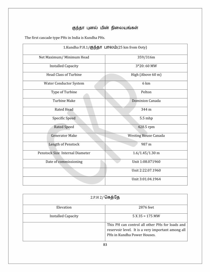
83
குந்ர னணல் றன் றஷனங்கள்
The first cascade type PHs in India is Kundha PHs.
1.Kundha P.H.1/குந்ர தரனம்(25 km from Ooty)
Net Maximum/ Minimum Head 359/316m
Installed Capacity 3*20: 60 MW
Head Class of Turbine High (Above 60 m)
Water Conductor System 6 km
Type of Turbine Pelton
Turbine Make Dominion Canada
Rated Head 344 m
Specific Speed 5.5 mhp
Rated Speed 428.5 rpm
Generator Make Westing House Canada
Length of Penstock 987 m
Penstock Size Internal Diameter 1.6/1.45/1.30 m
Date of commissioning Unit 1:08.071960
Unit 2:22.07.1960
Unit 3:01.04.1964
2.P.H 2/ வகத்ஶ
Elevation 2876 feet
Installed Capacity 5 X 35 = 175 MW
This PH can control all other PHs for loads and
reservoir level. It is a very important among all
PHs in Kundha Power Houses.
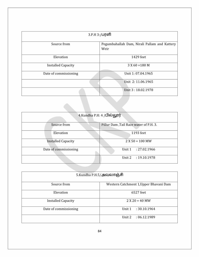
84
3.P.H 3:/தபி
Source from Pegumbahallah Dam, Nirali Pallam and Kattery
Weir
Elevation 1429 feet
Installed Capacity 3 X 60 =180 M
Date of commissioning Unit 1: 07.04.1965
Unit 2: 11.06.1965
Unit 3 : 18.02.1978
4.Kundha P.H: 4 /தில்லூர்
Source from Pillur Dam ,Tail Race water of P.H. 3.
Elevation 1193 feet
Installed Capacity 2 X 50 = 100 MW
Date of commissioning Unit 1 : 27.02.1966
Unit 2 : 19.10.1978
5.Kundha P.H.5/அனரஞ் ற
Source from Western Catchment 1,Upper Bhavani Dam
Elevation 6527 feet
Installed Capacity 2 X 20 = 40 MW
Date of commissioning Unit 1 : 30.10.1964
Unit 2 : 06.12.1989

85
6. Kundha P.H. 6/கரட்டு குப்ஷத
Source from Western Catchment 2 &3, Porthimund Dam,
Parsons Valley Dam
Elevation 6518.95 Feet
Installed capacity 1 x 30 = 30 MW
Date of commissioning 20.03.2000
7.Pykara/Singara P.H.
Source from Mukuruthy Pykara,Sandynallah and Glenmorgon
Dam
Dam Capacity 351 Cusec
Elevation 3400 feet
Installed Capacity 59.2MW
3 X 7 MW + 1 X 11MW+2X13.6 MW
Date of commissioning Unit 1 : 09.06.1933
Unit 2 : 22.11.1932
Unit 3 : 05.09.1932
Unit 4 : 28.08.1939
Unit 5 : 30.05.1954
Unit 6: 11.06.1954
8.PUSHEP/ றங்கரர;(டன்ணல் தர் யவுஸ்)
Main Reservoir னக்குனத்ற,ஷதக்கரர, ரண்டில்னர,

86
கறவபன் ரர்கன்
Installed Capacity 3*50 MW
Year of commissioning 2005
9.ஶரரர் தர் யவுஸ்
Installed capacity 3*12 MW
Elevation 609 m
Source Moyar Forebay Dam, Maravakandy Dam,
Pyakara Power House tail race
Year of commissioning 1953
னக்கற ரி ர்ரர்கபின் (,ஷதக்கரர,குந்ர றகபின்) வகரள்பவு
(டிம் ற/ற.னேணிட்டில்):
னக்குறுத்ற 1.80/151
ஷதக்கரர 2.00/163
ரண்டில்னர 0.87/063
அப்தர் தரணி 3.00/356
தரர் ன் ஶல்னற 0.48/054
ஶதரர்த்றண்ட் 1.85/208
அனரஞ் ற 2.14/215
ரல்ட் 3.30/332
தில்லூர் 0.94/004

87
வரத்ம் 16.38/1546
இந் னணல் றன் றஷனங்கள் ரம்(வறும் 1546 றல்னறன் னேணிட்டுகஶப ன்நரலும்) கறரிட் ஆப்தஶனுக்கு றகவும் டஷ னரிதஷ!
தகீ் யர் ஆப்தஶனுக்கும், றட்டறடர தரிர்த்ஷணஷ (Unscheduled
Interchange) கட்டுக்குள் ஷத்றனக்கவும், அய்ன் அஷத்வுடன் ண்ரீ் னகனம் கிஷந தரறக் கறற்நறல் ிட்டுிட்டு ஏடினம் ரசுகறஷப் ஶதரன, கடுகற ந்ட கரப்தரற்றுதஷ!!!
ல்ன ஷ வதய்ட 10.6.'18னறனந்ட தில்லூர் ர்ப்பஸ் ஆகறநட.அணரல்,இந் ிம் அஷணனம் அநற!
குந்ர,ஷதக்கரர னணல் றன் றஷனங்கஷபப் தற்நறச் வ ரல்லும் ஶதரட, 2013-'14ல், தரணி தர ண ி ரிகள் ங்கங்கள்,
தரணிக்கு ட ரி ர்ரர்கபினந்ட அர்கள் தர ணத்றற்கரகத் ண்ரீ் றநந்ட ிடச் வ ரல்னற வ ன்ஷண உர் ீற ன்நத்றல் க்கு வரடர்ந்ஷ வ ரல்ன நந்ட ிட்ஶடன். அட என னக்கறரண க்கு,ரன் ந்றத் க்குகபில்(அஷ தற்நறத் ணிரக என தறவுனம்)!!!.
ஶற்வ ரன்ண ரி ர்ரர்கள் அஷணத்டம் றக றன் ரரித்றற்கு வ ரந்ரணஷ,ம்ரல் தரரிக்கப்தடுதஷ!!PWD கட்டுப்தரட்டில் னதஷல்ன!ஆணரல்,ப்ஶதரஶர PWD ஶதரட்ட என ஜற.ஏ.ஷ ஷத்டக் வகரண்டு அர்கள் க்கர(ட்)டிணரர்கள்!! ஆணரல்,அஷ உச் தட் றன் தல ஶ இக்கத்றற்கும், UI கட்டுப்தரட்டிற்கும் அ றம் ன்தஷ னறனேறுத்ற, ண்ரீ் ிடும் ஶதரட அர்கள் தன்டுத்றக் வகரள்பனரம் ன்று உத்றவு வதற்நட என ல்ன ிம்.
ஶ ரரரஜளலு(AG), கஶ ன்,ரறற, னகஶந்ற ஶதரன்ந ட வதரநறரபர்கபின் உிரல் இட ரத்றரணட. ன்நற.

88
ரன் LDல்(PP) இனந் ஶதரட னல் க்கு:
1. JSW /கர்ரடகரினறனந்ட 300 MW க்கு ந்ட வகரண்டினக்கும் ஶதரட,
கர்ரடகர E.A.Sec 11 அனல்தடுத்ற JSW தஷ அர்கஶப டுத்டக் வகரல்ன றட்டறட்டரர்கள்.னொல் தகுறகபில் ர ரிரக 8 ி ஶம் ஶனரட் வட்டிங் ஶதரய்க் வகரண்டினந் ஶம்!!
ரனம் E.A.Sec 11 அனல்தடுத்றத் ரணினந்ஶரம்.இந்டடிக்ஷக ரரித்றற்கரணட ன்தஷ ிட வஜணஶட்டர்கலக்கரணட ன்தஶ ரிரக இனக்கும்.வ க்ஷன் 11 என ர்வஜன் ற தர்.அஷண அடிக்கடி அல் தடுத்டட றன் ர ட்டங்கஷப வகரச்ஷ தடுத்டஶரகும். என வதரி வஜணஶட்டர் ஏணர் (கரனறந் கண்ட கவுண்டர்தரர்ட்) ன்ணிடத்றல் CMD
னன்ணிஷனிஶனஶ, ரன் றஷணத்ரல் ரஷபஶ வ க்ஷன் 11
அனரக்கத்ஷ த்ட வ ய் னடினேம் ன்று வ ரன்ணஷ றஷணவு கூர்ந்ரல் உண்ஷில் ரர் றர்ரகம் தண்டகறநரர்கள் ன்தஷ உ னடினேம்!!! ஆணரல்,அற்கு னன்ன இனந் தர்ஶ ஸ் ஆர்டர்கஷப அட கட்டுப்தடுத்ரட ன்தஶ ட ரரக இனந்ட. உச் ீற ன்நம் வ ன்ஶநரம்!! அந்ற அர்ஜளணர ட க்கநறஞர்.என அப்தின்மறற்கு 3.5 னட் ம்(கணிக்கவும் ஜஸ்ட் ஶரற்நபித்ரஶன ஶதரடரணட).அஃன்ணிில் கரன்ஃதன்மறற்கு னென்நறல் என தங்கு ரர்ஜ்!! க்கு டந்ட வகரண்டினக்கும் ஶதரஶ ற.தி. றங்கரல் அவுட் ஆஃப் ஶகரர்ட் டடிக்ஷக னெனம் தரற தரறரக திரித்டக் வகரண்டு வ ட்டில் வ ய்ப்தட்டுிட்டட.
2. அடுத்ட,றன் கட்டஷப்தின்(Grid) அறர்வண் ஶதண்ட் ிட்ஷ சுனக்குற்கு றரக ரம் உ.ீ.ன்நம்,
வ ன்ஷணில் வரடர்ந் க்கு:
1.2.2000 ஷ IE Rules 1956 இன் அடிப்தஷடில் றன் கட்டஷப்தின்(Grid)
அறர்வண் இங்கு ல்ஷன 48.5 to 51.50 Hz ஆக இனந்ட ந்ட. திநகு,1.2.2000
இல் 48.5 to 50.5 ன்தரக ரற்நப்தட்டட. அடுத்ட 1.4.2002 இனறனந்ட 49.0 to 50.5 ஆக ரற்நப் தட்டட.

89
3.5.2010இனறனந்ட 49.5 to 50.2 ன்று உத்ிடப்தட்டட. இட ஷ ரிஶ!
அடிக்கடி கறரிட் திபரக் அவுட் ஆட இணரல் ரன் ன்று றனர் னடிவுக்கு ந்ணர். 30.7.'12 /2.00 AM அபின,் ரர்த்ர்ன் கறரிட் திபரக் அவுட் ஆண ஶதரட இனந் அறர்வண் 50.20 Hz. யரர்ட் அட்டரக், ஷய B.Pஇல் ரன்
னும் ன்நறல்ஷன; B.Pரர்னரக இனக்கும் ஶதரட கூட னரம்! Grid collapse
may occur due to sudden outage of generators and also tripping of critical transmission elements
resulting cascade trpping. Grid inertia (வ்பவு அடிச் ர ரங்கும் ன்னும் அபவு) கறரிட் அறர்வண் குஷநரக இனக்கும் ஶதரட வகரஞ் ம் கீ்கரகற கறரிட் வகரனரப்மரக ரய்ப்ன அறகம். இனந்ரலும்,ஶனர ஃதிரிவகரன் ற ட்டுஶ றச் ம் ப்ஷப திபரக் அவுட்டிற்கு கரறல்ஷன!ஆணரல்,ணிரர் டஷநிணர் றஷந றன் றஷனங்கள் அஷத்றனந்ரலும், றஷந ரறனங்கள் றன் தற்நரக்குஷநில் ப்தடிஶர ட்டுத் டுரநற ரபித்ட ந்ரலும்,அற்ஷந தர் தர்ச்ஶ ஸ் தண் ஷப்தற்கரக றஇஆர் ற வகரண்டு ந் ஷநனகத் றட்டம் ரன் அடுத்ட 1.2.'12இனறனந்ட ஶலும் கறரிட் அறர்வண் இங்கு ல்ஷனஷ 49.7 to 50.2ஆக குறுக்கும் னற் ற!!!
இந்றரின் அஷணத்ட ரறனங்கலம் இற்கு எப்னக் வகரண்ட ஶதரறலும்,ரம் ட்டும் 4000 வகரரட் தற்நரக்குஷநரல் சுரர் 8 ி ஶத்றற்குக் குஷநரல் ஶனரட் வட்டிங் தண்ிக் வகரண்டினந்ரல்,
அந் அறர்வண் இங்கு ல்ஷன குறுக்கும் உத்ிற்கு உர் ீற ன்நத்றற்கு வ ல்ன ஶண்டிரிற்று. க்கநறஞர்கலக்கும்,
ீறதறகலக்கும் இற்ஷநவல்னரம் னரி ஷத்ட ஸ்ஶட ஆர்டர் ரங்கற ,தித்ணப்தட்டு ரரடி இறுற ஆஷ னம் றஷனில், றர்தரர ிரக(????) 30.7.'12 ற்றும் 31.7.'12 அடுத்டுத்ட இண்டு ரட்கள் ரர்த்ன் கறரிட் வகரனரப்மரகற, தர் கறரிட் ஆட்கள் ஸ்ஶட ஆர்டஷ அற்கு கரரய்க் கரட்டி ரரட ட தக்கம் ஶரற்று 17.9.'12இனறனந்ட 49.7 to
50.2 Hz அறர்வண் இங்க உத்ிஷண கஷடதிடிக்க ஶண்டிரிற்று. ப்தடிினப்தினும் ,CERC ஆர்டஷ 7 ரங்கள் ள்பிப் ஶதரட்டஶரடல்னரல் அதரம் கட்ட ஶண்டி னஷ ிர்க்கவும் னடிந்ட!

90
இந் அறர்வண் குறுக்கு டடிக்ஷகிணரல் ஶனரட் வட்டிங் அறகரணடம், திநகு ந்டி தண்ரல்17.2.'14னறனந்ட CERC 49.9.to 50.05 Hz
ன்று ஶலும் குறுக்கறடம் ,சூடு தட்ட னஷணரய் ,ஶறு றின்நற ,ரங்கள் ரய்னெடி வௌணிரக இனந்டவும் ஶ ரகக் கஷ!! இப்தடிரகத்ரஶண டந்ட அறர்வண் இங்கு ல்ஷன +/- 1.5 டூ 3 Hz) (48.5
to 51.5) இனறனந்ட வறும் 0.15 Hz ஆக சுனங்கறப் ஶதரகற, திஷஶட் வஜணஶட்டர்ஸ் வகரழுத் னரறும்,அட வரடர்தரண க்கும்!!
3. அடுத்ட, கரற்நரஷனகபின் ஸ்ட் ன் க்கு ,வ ன்ஷண உர் ீறன்நத்றல்!
கரற்நரஷன றன் உற்தத்றின் ம்திக்ஷகற்ந ன்ஷ,ரறும் இல்ன,
ிட்டுிட்டு னல் ன்னும் இற்ஷக இல்னகபரல் ,கறரிட் ஶகரடு தடி கறரிஷட இக்குட ரத்றற்நட ன்தரலும்,றன்கட்டஷப்தின் தரடகரப்திற்கு இத்ஷண வதனம் அபவுள்ப கரற்நரஷன றன் ரம் குந்கம் ிஷபிப்தரலும், ட அணல் றன் றஷன அனகுகஷப அடிக்கடி வஜணஶன் ற்நற இநக்கறக் வகரண்டினந்ரல் தரய்னர் டுனேப் தன்ச் ர் அடிக்கடி ற்தடுரலும், கரற்நரஷனகபின் வரத் உற்தத்றில் 70 ீம் ிண்ட் றதிதிில் இனப்தரலும் ரம் ட றன்றஷனங்கலக்கும்,
தன் தடுத்றணரலும், தடுத்ரிட்டரலும் றஷன ிஷன வகரடுக்க ஶண்டினேள்பரலும் அற்நறற்கு ட்டுஶ னன்னுரிஷ அபித்ட,அற்நறற்கு திநகு கரற்நரஷனகஷப தன்தடுத்ற ந்ஶரம். அஷண றர்த்ட அர்கள் வரடர்ந் க்கறல் ரன்,ரம் கறட்டத்ட்ட என னடத்றற்கு ஶல் வரடர்ந்ட உர் க்கரடி ீறன்நத்றல் ந்ஶரம்.கஷட றில், ரம் ஆம்தத்றல் ,ீறன்ந ல்ஷனக்குள் இட ரட,டின்இஆர் ற ரன் ி ரரிக்க ஶண்டும் ன்று வ ரன்ணஷஶ உத்ரக்கற ள்பி ிட்டு ிட்டரர்கள்! TNERC என னடம் ி ரரித்ட ிட்டு ,இண்டு உறுப்திணர்கபில் எனத்ர் ரரித்றற்கு றரக ஶதரட்ட உத்ிஷணப் திடித்டக் வகரண்டு,
அற்கு அப்தலீுக்கும் ஶதரகரல் ரரித்றற்கு வதனத் ட்டரகறக் வகரண்டினக்கறநட. ட ஶதஸ் வஜணஶன்,ஃதிக்மட் ரர்ஜ் கட்டஶண்டி றஜறஸ் ஶர் ,கண்வண்ணல் றதிதி அஷணத்ஷனேம் னநந்ள்பி ிட்டு,

91
ஶ றப்ன ற ங்கப் தட்டுள்ப ிண்ட் றதிதி னீறங்கறற்கு னன்னுரிஷ வக(வகர)டுத்டக் வகரண்(டி)(நற)க்கறஶநரம்.
1.4.18 க்கு திநகு கறரிடிற்குள் னம் கரற்நரஷனகலக்கு ட்டுஶ no banking
facility வதரனந்டம்.இற்கு னன்ன,கறட்டத்ட்ட 5000 வகர ரட் ிண்ட் றதிதி னீறங் அக்ரிவண்ட் உள்ப கரற்நரஷனகலக்கு ஶ றப்ன ற வரடர்கறநட.
அட ரன் ம்ஷ அறப்தட!!! அற்ஷந ஶ ரனரனக்கு இஷரக வகரண்டு ந்ரல் ட்டுஶ ரரிம் திஷக்கும். ரன் LD ல் இனந் ஷ ட வஜணஶனுக்கு ட்டுஶ னன்னுரிஷ வகரடுத்ஶன்!!
தண்தரடு ஶத றப் ஶத ற வதண்தரடு வதனம்தரடு ஆக்கறஷப் ஶதரன, கறரீன் ணர்ஜற, கறரீன் ணர்ஜற ன்று வ ரல்னற ட ரரித்ஷ வட்(ஶடஞ்ஜஸ்) ஶஜரணில் றறுத்றிட்டரர்கள் றக ஷரஸ்கள்!!!
To allow only least prioity for wheeling of CPP (both conventional & RE) on the basis that their
consumers are availing power from the grid at applicable tariff during absence of their CPP
generators is permissible. Even then, if it's preferred to give priority for wheeling,why not to
TANGEDCO first and then to CPPs & REs.In either way Tangedco thermal gen.will be saved during
wind season.Frequent failure of our own thermal units are the effect of frequent back down and
outage of thermal units. As per cl.3.95,(Tangedco T.O. dt.19.12.14),energy available from Must -Run
status Units will be dispatched first which in this case definitely must not include wheeling from
both conventional & nonconventional plants.
னீறங்கரல் ற்தடும் அறகப்தடி றன் ரத்ஷ , றதிதி டேகர்ஶரர்கபின் ர தணடீ்டபஶரடு அட்ஜஸ்ட் வ ய்ட ஶதரக ீறஷ CERC regulationதடி அறர்வண் இஷந் ிஷனப்தடி ரரித்றடம் அம்ரத்றஶனஶ ிற்றுிடுஶர,அல்னட ஶ ரனரர் திஶபண்ட் ிறனஷநின்தடி வ ல் தடுஶர ரன் இற்ஷக றறப்தடி ரிரணரக இனக்கும். இத்டஷ கரனம் ரரித்ஷ ட்டப் தடுத்றடஶதரடம், வதரன் னட்ஷடிடும் ரத்ஷக் வகரன்றுிடக் கூடரட ன்று அர்கஶப கனஷ வகரண்டு ிட்டரல் ட்டுஶ ரரித்றற்கு ிஶரச் ணம்!! ஆண்டன் ரன் இந் இக்கட்டினறனந்ட ரரித்ஷக் ிடுிக்க ஶண்டும்!!

92
4. கஷட றரக,இண்ட் தரத் தர் னறறட்டட்,டெத்டக்குடி வரடர்தரண ஆப்வடல் க்கு! இட என க்கறற்கு உகந் ிஶ அல்ன! E.A.2003 வ க்ஷன் 10(1)ன் தடி திஷஶட் வஜணஶட்டர்ஸ் ங்கள் வ னில், றஸ்டம் ஸ்வடடிின் ஆஶனர ஷணப்தடி ஶஷரண ஷனஷண அஷத்டக் வகரள்ப ஶண்டும்.ஆணரல் TNERC ஆர்டர் இண்ட் தரத்றற்கு ஆரகற ிட்டரல்(ந் கரனத்றல் ரரித்றற்கு ஆரக இனந்ட?) ரம் ஆப்வடல் வ ன்று ஆக்ட்டின் வ க்ஷன் 10(1) றஷன றறுத் ஶண்டிரகறிட்டட. APTEL 145 of 2011.
ற்நவல்னரம் றன்ண, றன்ண க்குகள்!! ல்ன அனுதம்!!
H.C.டிலும்,S.C.டிலும் ற்தட்ட னழு அனுதங்கஷபனேம் வ ரன்ணரல் கண்வடம்ப்ட் ந்டிடும்!!!அணரல்,இஶரடு ஶதரடம்!!!
118. ன்வ ய்ட லர்டெக்கும் ஶகரல் ஶதரல் அஷந்ட எனதரல் ஶகரடரஷ ரன்ஶநரர்க்கு அி.

93
FACTS ON POWER SYSTEM OPERATIONS
1. டிரன்ஸ்ஃதரர்ர் ஷண்டிங் அறகதட் ம் யரட் ஸ்தரட் வடம்ஶட் ர் ட ஷ அனுறக்கனரம்??
இஷண ீர்ரணிக்கும் னன்ன ட றன்ரற்நற 55°C ஷமர, 65°C ஷமர ன்று ஶம் திஶபட் டீட்வடய்ல்மறல் கணித்ட அற்ஶகற்நரறு யரட் ஸ்தரட் வடம்ஶட் ஷ ீர்ரணிக்கனரம். ர ரி சுற்றுப்னந வப்தறஷன
30°C ன்று ஷத்டக் வகரண்டரல், யரட் ஸ்தரட் வடம்ஶட் ர்:
30°+ 55°+15°
(allowance for hot spot):100°C.
For normal life expectancy, the hot spot temperature is limited to 100°C and 110°C for 55°C rise &
65°C temp.rise transformers respectively.
We adopt about 80°C and 90°C for oil temp.alarm and winding temp.trip respectively.
இஃன்ணிில்,DGA, உற்தத்ற னடம் ஶதரன்ற்ஷநனேம் கணத்றல் வகரள்ப ஶண்டும்.
2. What shall be the current and time setting adopted for earth fault tripping in the feeders?
The current setting may be 10 to 20% according to site and area conditions and time setting of
150 msec.
3. What is load encroachment in distance protection?
Load encroachment relates to the influence of load current on distance (mho) relay
sensitivity and settings. The load encroachment is about magnitude and angle of the load that
sometimes can enter in the tripping zones of 2 & 3. It's an issue for mho and quad type relays also.
What load encroachment can't help with is distinguishing fault location from one side of the next
relay to the other. If we want one relay to clear all faults between it and the next relay
instantaneously we must have some sort of communication between the relays.
We could also set an element in the upstream relay to trip after 3-4 cycles, if not blocked and then
set an element in the downstream relay to send a blocking signal if it also sees fault current.

94
Load Encroachment can be used with overcurrent relays as well as distance relays. The SEL-351
and -451 include load encroachment but have no distance elements. The results of the load
encroachment logic can be used to torque control overcurrent elements. Digital protections use
voltage memory to avoid polarisation problem. There is no restrection to use distance relay in
distribution ,but it is unusual to use a distance relay on a distribution feeder.
4. What is Power number???
The quantum of power required to rise/lower the grid frequency by one Hz is called
power number of that particular grid, also called as inertia of the grid.It is about 6000 MW for our
integrated Indian grid. For SR grid & TN,power number is 2000 & 600MW respectively.
அரட,கறரிடின் ரங்கு ன்ஷஷ அபிடுட. வ்பவு அடிச் ரலும் ரனம்,டவும் ரங்க னடிரட!ல்னரற்நறற்கும் என னறறட் இனக்கும்! அந் ஶனரட் ரங்கும் ன்ஷஷ றர்ணிப்தட ரன் தர் வம்தர்!! இஷண ஷத்ட ரன் எவ்வரன ஸ்ஶடட் கறரிடும் ,அறர்வண் இநக்கத்றன் ஶதரட ந்பிற்கு ஶனரடு வட் தண்(Under frequency load shedding) ஶண்டுவன்று SRLDC றர்ணிக்கும். கூடங்குபம் அனகு டிரிப் ஆகும் ஶதரட,765கறஶர ஶரனரப்னர்--வய்ச்சூர் ஷனன் டிரிப் ஆணரல் வகரடுக்க ஶண்டி ஸ்வதல்
னவட்வடக்ஷன் ஶனரடு ரிலீஃப் அஷணத்றற்கும் இந் தர் வம்தர் உவுகறநட. இஷண SRLDC, டு றஷனஷரகச் வ ய் ஶண்டும்(யறயறயற!!). கறரிடின் ஸ்வடதினறட்டிஷ கஷடதிடிக்க இந் தர் வம்தர் ஸ்வடடி தன்தடுகறநட.
5. What will be the primary fuse rating for a distribution transformer??
The primary fuse rating of a transformer primary must be based on the inrush current of
the transformer. The inrush was about 14 times the rated current for 0.01sec and 5 times the rated
current for 0.1 sec. So,the primary fuses must be 2 to 3 times the rated full load primary current.
வதரடரக கறரப் தகுறகபில் ,ஃனனைஸ் னக்குப் தறனரக 7/20 கரப்தர் கம்திகஷப கிறு றரித்ட ஶதரடுஷ ரரரகப் தரர்க்கனரம்.இஷண ரி வ ய்ரஶன ,DTs ஃவதினஷ கி ரகக் குஷநக்கனரம்.ட ரரித்றல், அறகதட் ம் DTs ஃவதினர் னடத்றற்கு 6%க்கு ஶல் றகக்

95
கூடரட ன்று அபடீு ஷத்டள்ஶபரம். அறக ி ர இஷப்னகள் உள்ப ிழுப்னம் ண்டனத்றல் ரன் DTs ஃவதினர் அறகரக உள்பவன்று றஷணக்கறஶநன்.2 டூ 3 தம்ப் வ ட் உள்ப வதனம் ி ரிகஷப அர்கபட வ ரந் வ னில் றங்கறள் ஶதரல் வுண்டட் DT ரங்கற ஷத்டக் வகரள்ப அனுறத்ரல்(ஶறு ரனக்கும் அறல் ப்ஷப வகரடுக்கக் கூடரட) ஏபவு ஃவதினர் குஷநரய்ப்னள்பட. ரன்,ிழுப்னத்றல் இனந் ஶதரஶ ஜ்ஜஸ்ட் தண்ஷ கரறல் ரங்கறக் வகரள்பில்ஷன. இஷ ல்னரற்ஷநனேம் ிட ரண DT ரங்கற ஷப்தட ரன் றகறக னக்கறரணட. இவல்னரம் டக்கறந கரரிரடர ண்ஷடர ன்று கவுண்டி ஶகட்தட கரறல் ிழுகறநட. கணவு கரடங்கள் ன்று கனரம் வ ரன்ணஷ நஶரம். *உள்லவல்னரம்* *உர்வுள்பல்......*
6. ட ிறஶரக றன் ரற்நறகஷபப் தற்நற என றறு குநறப்ன ஷக.
The standard voltage transformation of a Distribution Transformer (DT) is
11KV/433V with100,200,250,500 kVA with impedance of 4 %
The declared consumer voltage as per IE Rules is 415V between phases and 240V between phase
and neutral with a permissible voltage variation of +/- 6%. Thus a consumer at the near-end of the
distribution may have a voltage as high as 433V (3 phase) and 250V (1 Phase) during light load
hours, whereas, a consumer at the far-end may have a voltage as low as 400V (3 phase) and 230V
(1 phase) at peak load hours.
No-load current up to 200kVA shall not exceed 3% of full load current at rated voltage and
frequency. Increase of 12.5% of rated voltageshall not increase the no-load current by 6% of full
load current. No-load current of DTs of above 200kVA shall not exceed 2% of full load current at
rated voltage and frequency. Increase of 12.5% ofrated voltage shall not increase the no-load
current by 5% of full load current. The insulating oil of the DT shall be as per IS 335 and use of
recycled oil shall be avoided. The specific resistance of the oil shall not be less than 35 X10 power12
ohm-cm at 27 °C.
7. What is fault level and it's significance?
The maximum short circuit power that could occur in a particular bus is called the
fault(3 phase fault) level of that particular bus. என றன் தஸ்மறல் உண்டரகக் கூடி அறக தட் ஃதரல்ட் கண்ஶட அந் தஸ்மறன் ஃதரல்ட் வனனரகக்

96
கனப்தடும். அந் ஃதரல்ட் வனஷன அந் தஸ்மறற்கு னன்னும்(ஶமரர்ஸ் இம்திடன்ஸ்), தின்னும் (டிரன்ஸ்ஃதரர்ர் இம்திடன்ஸ்) உள்ப இம்திடன்ஸ்கள் ீர்ரணிக்கறன்நண. 110 kV ஶடில் ஸ்ஸ்கபின் ஃதரல்ட் வனஷன,
ம்ஆர்டினேம்,110 kV கறரிட் ஸ்ஸ்கபின் ஃதரல்ட் வனஷன ஜறஆர்டினேம்,230 kV
தஸ் ஃதரல்ட் வனஷன றஸ்டம் ஸ்வடடினேம் கக்கறட்டு அனுப்னரர்கள்.
230 kV,110 kV, 33 kV, 11 kV fault level SS இல் display தண்ிினக்கறநர ன்தஷ
SS AE & AEE உறுற வ ய்ட வகரள்ப ஶண்டும். அஃன்ணிில்,அந்ந் தஸ்கபில் உள்ப திஶக்கர்கபின் திஶக்கறங் கண்ட், அந்ந் தஸ்கபின் அறகதட் ஃதரல்ட் கண்ஷடிடவும் அறகரக உள்பர ன்தஷ உறுற வ ய்ட வகரள்ப ஶண்டும். அப்தடிில்னர தட் த்றல் ,அந் திஶக்கர்கள் ஃவதினரக ரய்ப்னள்பரல், அற்ஷந ரற்நற ிட ஶண்டும்.
டிரன்ஸ்ஃதரர்ர்கள் இஷ இக்கத்றன் ஶதரட அந் தஸ்மறன் ஃதரல்ட் கண்ட் அறகரிக்கும் ன்தரல்,ஸ்திபிட் தஸ் இக்கத்றன் னெனம் ஃதரல்ட் கண்ட்ஷடக் குஷநக்கனரம்.
ஃதரல்ட் கண்ட் றன் ரணங்கபின் ீட வர்ல்,னக்ட்ரிக்கள் ஸ்ட்வஸ்ஷம உண்டரக்குரல் அற்நறன் இன்சுஶனன் றகவும் தரறக்கப்தட்டு ,அற்நறன் ரங்கு ன்ஷ,ரங்கும் ஶம் இற்நறற்குள் ஃதரல்ட் ினக்கப்தடில்ஷன ன்நரல் றன் ரணம் வடித்டிட டரகும்.
என SSன் அறக தட் ஃதரல்ட் கண்ட்ஷட 500 ஆல் குத்ட குஷநந்தட் ம் அத்ஷண ர்த் ரடுகபரட இனக்கறநர ன்தஷ உறுற வ ய்ட வகரள்ப ஶண்டும்.அரட,என SSன் ஃதரல்ட் வனல் ரன் அந் SSன் திஶக்கர்கபின் றன் னநறவுத் றநஷணனேம், ர்த்கறரிடின் தப்தபஷனேம் ீர்ரணிக்கறன்நண.
8. How to calculate the fault level of a 110 kV bus at 230 /110 kV substation?
னென்று றனஷநகள் உள்பண. கலழ்க்கண்டட பிரணட.
97
Example:
230 kV bus fault level say (இட System Studies னரர்கள்):15000 MVA ன்று ஷத்டக் வகரள்ஶரம்.
Three nos.230/110 kV,100 MVA auto transformers with percentage Impedance of
11.86,12,23,11.57 % இனப்தரகக் வகரள்ஶரம். Transformer equivalent % Impedance
=1/(1/11.86+1/12.23+1/11.57)=3.96%
Tr.eq.Imp p.u.value . = 3.96%/100 =0.0396 pu.
System impedance = Transformer MVA/ System fault MVA = 300/15000= 0.0200pu
Total impedance for fault = 0.0396 +0.0200=0.0596 pu
110 kV bus Fault MVA =Total Trf Capacity/Net Impedance in p.u.(Source to fault) =300
MVA/0.0596 Z (p.u) =5033 MVA
Isc=5033 MVA / (1.732x110 kV)=26.42 kA.
இந் குநறப்திட்ட 110 kV தஸ்மறல் உள்ப திஶக்கர்கபின் திஶக்கறங் கண்ட் ,ஶல்தடி அறக தட் ஃதரல்ட் கண்ட்ஷடிட( 26.42 kA) அறகரக உள்பர ன்தஷ உறுற வ ய்ட வகரள்ப ஶண்டும். ன்ஷணத் ரஶணக் கரப்தரற்நறக் வகரள்ப னடிரணரல், திநஷ ங்கணம் கரப்தரற்ந னடினேம்??
ணஶ,ஷனஷணனேம், றஸ்டத்ஷனேம் கரப்தரற்ந ஶண்டி திஶக்கர், ரன் வடித்டச் றநரனறனக்க அன் டிஷக்கப்தட்ட னநறவு றநன், அந் தஸ்மறல் உண்டரகக் கூடி அறகதட் தழுட அபஷிட ஶம்தட்டு இனப்தட றகவும் அ றரகறநட!!!!
றன் தழுட அபில் அறக தட் தழுபவு, குஷநந் தட் தழுபவு ன்று இண்டு ஷகரக கக்கறடப்தடும். அஷணத்ட றன் ர இக்கறகலம் ங்கபட அறக தட் உற்தத்றினறனக்கும் ஶதரட (and also at minimum impedance)
உண்டரகக் கூடி னம்னஷண குறுக்கறஷப்ன கண்ட் அறக தட் தழுபவு ஆகும். இட ரன் றன் ரணங்கபின் றநஷணனேம், றன இஷப்ன அஷப்ஷதனேம் ீர்ரணிக்கறநட.
98
றன் உற்தத்ற ஶதஸ் வஜணஶன் அபினறனக்கும் ஶதரட (and also at maximum
impedance) உண்டரகக் கூடி னம்னஷண குறுக்கறஷப்ன கண்ட் குஷநந் தட் தழுபவு ஆகும்.இடஶ ரிஶன வ ட்டிங்ஷகனேம், இங்கு ஶ எனங்கறஷப்ஷதனேம் (relay coordination) ீர்ரணிக்கறநட.
9. Which is better location for providing CTs in distribution feeders?
Ideally each zone of protection uses CTs located across the breaker from the rest
of the zone so that the breaker is always in the zone of protection. So, it will be better that the
feeder protection CTs should be on the bus side of the breaker in the case of out door SS. ஆணரல்,
திஶக்கஶ ஃவதினரகும் ஶதரட CTs திஶக்கனக்கு னன்ணினப்தஶர,
தின்ணினப்தஶர வதரி அபில் தணபிக்கரட. அஶ ம்,இண்ஶடரர் 33 kV
SSல் ஃதடீர் திஶக்கரின் CTs out going side, அரட ஶகதிள் ஷ ட் ஷப்தட ரன் தரரிப்திற்கு றநந்ட.
10. Sympathetic tripping ன்நரல் ன்ண???
என வயல்த்ற ஃதடீர் அனுரதத்றல் E/L ரிஶனரல் டிரிப் ஆட!! ணிணிடம் கனஷண அனகற ிட்டரல், ரரட கூட ஶ ர்ந்ட டஷக்குப் ஶதரஶரஶ ன்று அனகறலுள்ப ஃதடீரின் E/L Relay, ஶவநரன ஃதடீர் உண்ஷர ர்த் ஃதரல்ட்டிற்கு டிரிப் ஆகும் ஶதரட,இட ம்தந்ஶ இல்னரல் கூடஶ டிரிப்தரகறத் வரஷனப்தட!!! இட ரன் றம்தத்ட்டிக் டிரிப்திங்!! இஷண,ரங்கள் வ ம்திம் SSல் அனுதித்றனக்கறஶநரம்!
If the non directional ground over current relay of one feeder relay is low set, this relay could
operate and trip it's feeder undesirably for the actual ground fault of another adjacent feeder which
is called as sympathetic tripping. When the fault happens on the adjoining feeder and the ground
fault current returns to the source SS,it is reflected in the adjacent feeder as residual current in the
E/L Relay of the healthy feeder and trips the healthy feeder. This may also happen in few cases,
where there is voltage dip during the fault of a feeder ,causes refrigeration compressors to stall.
Then, when the fault is cleared, all those stalled compressors see normal voltage, resulting in
drastic increase in current. Since it only one phase of the load that sees this increase, and the
unbalance E/L relay makes no distinction between ground fault and unbalance load, the ground
relay will respond resulting sympathetic tripping.

99
This phenomena occurs where a breaker trips for a fault on a nearby circuit, usually caused by
current inrush on a circuit after the faulty feeder breaker opens and the system voltage returns to
normal. This can be avoided by increasing the E/L Relay setting and decreasing the earth
resistance of the SS.
ர கனஷ தடரனறனந்ர அட ப்ன, அடஶ healthy feederஇன்
E/L Relay கனஷ தட்டர அடவும் ப்ன.
11. What are the points to be noted regarding blackening of enclosure bolts???
RMG ன்குஶபர ர் ஶதரல்ட்ஸ்,இண்ஶடரர் SS Cubical ஶதரல்ட்ஸ் கறுப்ன அடித்றனந்ரல், அற்ஷநப் னநக்கிக்கரல் ர்த்றங் இஷப்ன, ர்த் வ றஸ்டன்ஸ் ஶதரன்நற்ஷந ரிரக இனக்கறநர ன்று அ றம் தரர்த்டக் வகரள்ப ஶண்டும். Bolt tightness was supposed to be checked periodically in
accordance with the maintenance manuals supplied with the equipment. If it was enclosure bolts,
the removal of the ground wire could have lead to an arc forming from some conducting component
seeking ground, and found the bolts because they were extending into the air spaces ever so slightly
more than anything else. Once an arc started, it's conceivable that it burned right through one bolt
until it fell out, then to the other bolt because it too was the shortest distance.
Normally such burn out of bolts is due to current flow through them. When there is a gasket on the
flange the only path for current to pass on is through bolts. If the bolts are of stainless steel,the
burn out will be more.
So,ground bonding and earth connection & earth resistance should be checked periodically and
carefully.
12. றன் உற்தத்ற றஷனங்கள்,றக னக்கற டஷ றன் றஷனங்கபின் தஸ் ஃதரல்ட்டரல் வஜணஶன் /ஶனரட் னரஸ் இற்ஷநக் குஷநக்க ன்ண றனஷநகள் ஷகரபப்தடுகறன்நண??
The easiest thing would be to employ breaker-and-a-half, ring bus, or double
breaker double bus arrangement. In this way, a fault on any bus section or segment at most
removes only one line from service instead of all in that section. These configurations can also
mitigate similar consequences arising from breaker failure. This concept is routinely done in the
generating stations & very important substations when a bus fault or breaker failure could produce
undesirable results.

100
13. டிரன்மஃதரர்ரின் ந் வகதர றட்டிக்கு ஶல் டிஃதவண்றல் ரிஶன ஷக்கஶண்டும்??
இட னழுக்க வதரனபரரம் ரர்ந் டடிக்ஷக! வதரடரக ,10 ம்ி றன்ரற்நறகள் ற்றும் அற்கு ஶல் வகதர றட்டி
றன்ரற்நறகலக்கு டிஃதவண்றல் ரிஶன ஷக்கப்தடுகறன்நண. SEL-787 ரிஶன சுரர் 2.00 னட் ம் ிஷனவன்று றஷணக்கறஶநன்.பர்ந் ரடுகபில் 5
ம்ி றன்ரற்நறகலக்ஶக ஷக்கறநரர்கள். றன்ரற்நறகபில் னஷ்றங் CTs
இல்ஷனவன்நரலும், திஶக்கர் CTsகஷப கூடப் தன்தடுத்டடண்டு.
PS (Special Protection) Class CTs டிஃதவண்றல் னவடக்ஷனுக்கு தன்தடுத் ஶண்டும்(அறக Knee point voltage Vkக்கரக).
14. 338.குடம்ஷத ணித்ட எறப் னள் தநந்ற்ஶந உடம்வதரடு உிரிஷட ட்ன.
உடம்திற்கும் உினக்கும் இஷடஶ உள்பத் வரடர்ன ன்தட,
னட்ஷடஷ உஷடத்டக் வகரண்டு தநஷ தநந்ட ிட்டுப் ஶதரண னட்ஷட ஏடு ஶதரன்நஶ!! தநஷ வபிஶநற திநகு அட இனந் னட்ஷட ஏட்டிற்கு ன்ண கறஶர,அஶ ரன் உிர் ஶதரய்ிட்ட உடனறன் றஷனனேம்!!! ணஶ,ரழ்ின் றஷனரஷ உர்ந்ட ஶரகவும்,அன்தரவும் இனந்டட்டுப் ஶதரஶரஶ ன்கறநரர் அய்ன்!!!���
னெனம் அநறஶன்; னடினேம் னடிநறஶன்
ஞரனத்டள் தட்டடர் ரட டக்குடர!
அநறரஷரம் னத்ரல் அநறவுனல் வகட்டணடர!
திரிர ிஷணப்தணரல் தித்டப் திடித்ணடர!

101
னுரற ரன்கும் ரணரய் ங்கறணண்டர!
னுரற த்ற ஷனில் அகப்தட்டணடர!
ரரஷ ன்னும் ணத்றல் அஷனகறநண்டர!
ரரய் உனகஷணத்டம் ரட கனங்கறநண்டர!
கன்ணி ணரர! கன்ணி ணரர!!!-தட்டித்ரர்.���
15. What is the Critical Clearing Angle of Generators?
அற்கு னன்ன தர் Vs Load angle curve தற்நற அநறந்ட வகரள்ஶரம். The graphical representation of Power (Pe )and the load angle(δ) is called the power - angle curve
which is widely used in power system stability studies.
னன்ஶத வஜணஶட்டரின் ஶனரட் ஆங்கறல் தற்நற தரர்த்றனக்கறஶநரம். அட (δ ) ,90⁰ ஆக இனக்கும் ஶதரட அறகதட் தஷனேம்,திநகு அறகரிக்க அறகரிக்க சுரர் 120⁰ அபில் தர் ஸ்ிங் ஆஷனேம், அடஶ 180⁰ஆகும் ஶதரட தர் ரறுல் ஜஶீரரகற,றன் கட்டஷப்தினறனந்ட தஷ டுத்ட ஶரட்டரரக இங்க ஶரிடுகறநட!! அப்தடி ஶரட்டரரக இங்க ஆம்தித்ரல்,
அந் வஜணஶட்டரின் திஷம் னெனக்கு வதனம் ஆதத்ட உண்டரகும் ன்தரல்,ரிர்ஸ் தர் ரிஶன னெனம் தரய்னர்,டர்ஷதன், வஜணஶட்டர்,(B.T.G)
னும் னென்றும் டிரிப்தரகற அஷணத்டம் கரப்தரற்நப்தடுகறநட.
With this knowledge on Power angle curve we can define the critical clearing angle as the
maximum change in the power angle curve before clearing the fault without loss of synchronism.
That is, Critical clearing angle is the load angle at which the fault will be clear and the system
becomes stable. In other words, when the fault occurs in the system the load angle curve begin to
increase, and the system becomes unstable. The angle at which the fault becomes clear and the
system becomes stable is called critical clearing angle.

102
16. What is voltage stability in Power System?
ஆக்டிவ் தர் றஷனில் ற்தடும் ஊறு றன் கட்டஷப்தில்
றஷனற்நத் ன்ஷஷனேம், ரிரக்டிவ் தர் றஷனில் உண்டரகும் ரறுதரடு,றன் கட்டஷப்தில் ஶரல்ட்ஶடஜ் வகரனரப்ஷமனேம் ற்தடுத்டகறநட. Voltage stability in the power system is the ability of a power system to
maintain acceptable voltages at all bus in the system under normal condition and also after being
subjected to a disturbance.
In the normal operating condition ,the voltage of a power system is stable, but when the fault or
disturbance occurs in the system, the voltage becomes unstable resulting in uncontrollable decline
in voltage.
Due to the voltage instability, a power system may undergo voltage collapse, (a very low voltage
profile in the essential part of the system) if the post-disturbance equilibrium voltage near loads is
below acceptable limits resulting total or partial blackout.
Voltage Stability Limit:
The Voltage stability limit can be defined as the limiting stage in a power system beyond which no
amount of reactive power injection will raise the system voltage to its nominal state.
The system voltage can only be adjusted by reactive power injections till the system voltage
stability is maintained.
ஶரல்ட்ஶடஜ் நற வகட்டிநங்கற வகரனரப்மரக ஆம்தித்ட ிட்டரல் ,ரர் இன்ஜக்ஷன் கூட தனணபிக்கரல் ஶதரகக் கூடும்.
ஶரல்ட்ஶடஜ் ஸ்ஶடதிபரக இனக்கும் ஶதரட ட்டுஶ ரர் இன்ஜக்ஷன் றகுந் தனஷணத் னம்.
17. What are the classification of Voltage Stability:
1.Large-disturbance Voltage Stability.
2.Small-disturbance Voltage Stability
Large-disturbance Voltage Stability :

103
It is concerned with a system stability to control voltages following a large disturbance such as
system faults, loss of load, loss of generation. For determination of this form of stability requires the
examination of the dynamic performance of the system over a period sufficient to capture of such
devices as under load tap changing transformers, generator field, and current limiters.
Small-Disturbances Voltage Stability:
The operating state of a power system is said to have small disturbances voltage stability if the
system has small disturbances, a voltage near loads does not change or remain close to the pre-
disturbance values. The concept of small disturbance stability is related to steady state.
ிறக்குத் டஷ றன வன்னர்ப் தரங்கள் - வய்ம்ஷ குன்நர
வரறக்குத் டஷ னனகர னும் ரங்கள் - னன்ன வ ய்
தறக்குத் டஷ அன் தன்ணின ஶரலம் தந் ணி
றக்குத் டஷ டிஶலும் வ ங்ஶகரடன் னைனஶ!�
[26/06 6:31 am] CKP SIR: Prof.தடீ்டர் யகீ்ஸ் ன்ண கண்டு திடித்டள்பரர்??
கடவுபின் டகள் தற்நற ஆய்ந்ட வபிிட்டுள்பரர்.
18. What are the cleaning agents for electrical equipments?
(i) Carbon Tetra Chloride CTC.
(ii)Iso Prophynol Alcohol.
(iii) Collonite for bushing cleaning.
வக றன் ட்டும் தன் தடுத்ஶ தடுத்ரீர்கள்.சுனதத்றல் உனரட. ரர்ஜ் தண்டம் ஶதரட திஶபஷ் ஏரக ரய்ப்னள்பட.

104
19. What causes an arc flash?
An arc flash happens when an electric current flows through air gap between
conductors or between conductor and earth. 300 mA ஆர்க்கறங் கண்ட்ஶட ஃதர் உண்டரக்க ஶதரடரணட. ஆர்க்கறங் வப்தறஷன 5500 deg Celsius
அபினறனக்கும். ணஶ ஆர்க்ஷக அனட் றப் தடுத்க் கூடரட.
Arc Fault Circuit Interrupters (AFCIs)
are to be employed to prevent fire accidents in electrical installations.
ட ரட்டில் இட தன்தடுத்ப் தடுரகத் வரிில்ஷன.
ரம் இன்னும் ELCBஷஶ னழுஷரக தன் தடுத்ில்ஷனஶ!!!
20. What is reactive power?
The magnetic coupling needed to produce work by induction machines is
contributed only by the reactive power, VAR/KVAR/MVAR. This is supplied by Generators and
Capacitor( transmission lines also feed MVAR only due to their inherent capacitance with mother
earth).
In generators,by increasing the excitation current in the field(rotor) ,the magnetic coupling of the
rotor with the stator is strengthened and MVAR output is increased.
21. One kWhr is equal to how much thermal units?
One kWhr:859 kCalories or 3412 BTUs.
22. Why the non polarity terminal of CT is grounded?
(i)To avoid inducing of high electrostatic voltage from secondary winding to ground.
(ii)If not earthed,relative voltage could be experienced during transit conditions.

105
23. Write a short note on Insulation Tester(Megger).
It is a high range resistance Mega ohm meter with a built in D.C.generator. It has both
voltage & current coils and read ohms directly independent of the actual voltage applied.It is a non
destructive method of measuring IR values. Megger measures the leakage current in micro amps
and calibrated in mega ohms. The temperature of the test equipment is more important as IR value
halve for every 10 deg rise and double for every 10 deg decrease and the base temp. of 20 deg C is
adopted for comparing the values in trend.
வக்கர் லீட், குநறப்தரக றன் ரணத்றல் ஶதரடும் எர் ீபம் குஷநரக இனப்தட ல்னட.ரன் AE/MRT/TVR ஆக இனந் ஶதரட, AEE/GRT ஆட்ஶடர டிரன்ஸ்ஃதரர்ஷ வக்கர் தண்டம் ஶதரட, அன் ஶஶனஶ ஷத்ட வக்கர் தண்ட றஷணில் உள்பட. The IR values should be considered as relative
value and what really matters is the trend in readings over a period of time. Low IR value but
steady at different intervals:No danger. High IR value but drops towards lower value:Locate and
remedy the cause.
500 V megger are used for LT & 11kV equipments and Power megger (2.5 to 5.00 kV) for 33 kV
and above. வதரடரக,IR ஶல்னே kVக்கு 2 வகர ஏம்மரட இனக்க ஶண்டும்.ஆணரல்,100 வகர ஏறல் றன் ரண ் ஃவதினரடம் உண்டு;
20 வகர ஏறல் றற்தடம் உண்டு.
The IR value actually does not indicate how strength is the insulation ,but warns how weak the
insulation is. That is why Polarisation Index Value /Dielectric Absorption Ratio (PIV) is measured
and considered some what reliable.
அரட,அடிப்தஷடில் இன்சுஶனன் றஸ்டத்றல் டி ற ஶரல்ட்ஶடஜ் ந்ரல் அற்நறன் அடக்கள் வதரனஷ ரகற IR ஶல்னே அறகரக ஶண்டும்.அட ந் அபவு அறகரகறநட ன்தறனறனந்ட
ஈம்,கண்டரறஶணஷண அட ந் அபவு உநறந்டள்பட ன்று அநறந்ட வகரள்பனரம். அஷணக் கண்டு திடிப்தட ரன் PIV அபடீு.
24. What is PIV?
PIV:10 Minute IR value / One Minute IR value .
If PIV is less than one : Dangerous.

106
1 to 2: Questionable.
2 to 4: Good.
More than 4: Excellent.
25. Write a short note on battery.
In an electrical cell, chemical energy is converted directly into electrical energy
whereas the chemical energy in the coal is converted into thermal energy in a boiler ,mechanical
energy in the turbine and electrical energy in a generator. A battery is a set of cells connected in
series(mostly) or parallel.
வ ல்னறன் தர றட்டிவ் ன்தட ,அட னக்ட்ரஷண வபிிடும் க்ற வகரண்டட; வகட்டிவ் ன்தட னம் னக்ட்ரன்கஷப ரங்கறக் வகரள்லம் றஷனில் உள்பட.றன்ஶணரட்டம் ன்தஶர னக்ட்ரன்கள் ஏட்டத்றற்கு ஶர் றரணட. வ ல்கள் இண்டு ஷகப்தடும்.அஷ, திஷரி ற்றும் வ கண்டரி வ ல்கபரகும்.
ஶரல்டரிக் வ ல்,
ஶடில் வ ல்,
வனக்னரன் ற வ ல்,
னன் ன் வ ல்,
ஃனல் வ ல் ஶதரன்ந றுதடினேம் ரி ரர்ஜ் தண் னடிர வ ல்கள்,
திஷரி வ ல்கள் ஆகும். இற்நறல், ிஞ்ஞரணி ஶரல்டர கண்டுதிடித் ஶரல்டரிக் வ ல்னறன் ஶரல்ட்ஶடஜ் 1.10 V ன்தடம்,அஷண வகௌிக்கஶ 110,220V,11kV,22kV,33kV,66kV,110kV,220kV ன்று குநறப்திடுரகவும் வ ரல்னப்தடுட உண்டு. (ஃதரர்ம் ஃஶதக்டனக்கரகக ன்றும் வ ரல்ரர்கள்).
வதரட்டண்றல் டிஃதவன்மறன் னேணிட்டும் அர் ஶதரஶனஶ ஶரல்ட் ன்நஷக்கப்தடுகறநட.
அடுத்ட,றுதடி,றுதடி ரி ரர்ஜ் தண்க் கூடிஷ வ கண்டரி வ ல்கபரகும்.
107
அஷ,வனட் ஆ றட் வ ல், டி ன் ஆல்கனற, றக்கல் - கரட்றம், னறத்றம் -அன் ஶதரன்ந வ ல்கபரகும். அஃன்ணிில்,PV, Thermo couple, atomic, piezo electric
ன்று தனஷக வ ல்கள் உள்பண.
ரம்,ம் றன் ற்றும் டஷ றன் றஷனங்கபில் வகுரகப் தன்தடுத்ப்தடும் வனட் ஆ றட் வ ல் தற்நற தரர்ப்ஶதரம்.இறஶனஶ,வட் வ ல், லல்ட் வனட் ஆ றட் வ ல்,ஃகறபரஸ் ஶட் ன்று னென்று ஷக உள்பண.
இறல்( Wet cell) வனட் ஆக்ஷமட்(PbO2) ஆஶணரடரகவும், ஸ்தரன்ஜ் வனட்(Pb),
ஶகத்ஶரடரகவும், ல்னரிக் ஆ றட் (H2SO4) னக்ட்ஶரஷனட்டரகவும் தன்தடுத்ப்தடுகறநட. இஷ றன்னூட்டம் ற்நப்தடும் ஶதரட, தர றட்டிவ் திஶபட்டில் வனட் ஆக்ஷமடரகவும்(PbO2), வகட்டிவ் திஶபட்டில் வனட் ல்ஶதட்டரகவும்(PbSO4) , னக்ட்ஶரஷனட்டில் H2SO4 ஆகவும் இஷகறநட. அடஶ,ஶதட்டரி வ ட்டினறனந்ட ஶனரடு டுக்கும் ஶதரட,றுஷன ரறுல் ற்தட்டு,இண்டு திஶபட்டுகபிலும் வனட் ல்ஶதட்(PbSO4) தடிஶரடு,
னக்ட்ஶரஷனட்டில் ண்ரீ்(H2O) ஶ ர்ந்ட ீர்த்ட ஶதரகறநட.இஷண ஈடு வ ய்த்ரன் ஃனஶபரட் ரர்ஜறங்கும்,கந்க அறனத்றன் (H2SO4) அடர்த்ற ண் (Sp.Gravity) வகுரக குஷநந்டள்ப ஶதரட(1185) குிக் ரர்ஜறங்கறலும் ஶதரட்டும் ரர்ஜ்(1220) தண்டகறஶநரம். வதரடரக,என வ ல்னறன் வரத் தர றட்டிவ் திஶபட்ஷடிட, அன் ஆக்டிவ் வட்டீரினறன் வ ஷன னழுஷரகப் தன்தடுத்றக் வகரள்ற்கரக,என வகட்டிவ் திஶபட் கூடுனரக இனக்கும். அரட, வகட்டிவ் திஶபட்டில் ஆம்தித்ட வகட்டிவ் திஶபட்டிஶனஶ னடினேம்.ணஶ,வரத் திஶபட்டுகபின் ண்ிக்ஷக ப்ஶதரடம் எற்ஷநப் தஷடரகஶ இனக்கும். வகட்டிவ் திஶபட், தர றட்டிவ் திஶபட்ஷடிட வனறரக இனக்கும். The formula for AH is the number of plates minus one times the AH per plate.
வ ல்னறன் ரர்ல் வப்தறஷன 25 deg C ன்தஷனேம், அறகதட் வப்த றஷன 45 deg C ன்தஷனேம் றஷணில் வகரள்ஶரம்.னக்ட்ஶரஷனட்டில் உள்ப ண்ரீ் ஆிரகற ீரிப்ன ற்தடுரல் ,அன் வனல் குஷநந்ட ிடும்.அஷண,அவ்ப்ஶதரட டிஸ்டில்ட் ரட்டர் ஊற்நற டரப்அப் வ ய்ட றக அ றம். இல்ஷனஶல், வ ல் திஶபட்டுகள் ஆக்ஜற னுடன் ஶ ர்ந்ட

108
ரிரக்ட் தண் ஆம்தித்டிடும். (ஆணரல்,தரரிப்ன ஶஷப்தடர லல்ட் வ ல்கபில்,(Valve Regulated Lead Acid / VRLA ) னக்ட்ஶரஷனட் வஜல்னரக திஶபட்டுகபின் இஷடஶ ஷக்கப் தட்டினப்தரல் ,ஈகுஷன றங் ரர்ஜறங் ஶஷினக்கரட.ப்தர் ஸ்டரப்தர் ீர் ஆிரகற வபிஶநரல் டுக்கறநட.அறலுள்ப றநற ஏட்ஷட ஷயட்ஜன் ஶகஸ் வபிஶந றஷக வ ய்கறநட). வ ல் ஶரல்ட்ஶடஜ் 1.85க்கு குஷநரலும்,Sp.Gr.1185க்கு குஷநரலும் தரர்த்டக் வகரள்ப ஶண்டும். என ஶதட்டரி வ ட்டின் வரத் இண்வடர்ணல் வ றஸ்டன்ஸ்க்குச் ரக அன் ஶனரட் வ றஸ்டன்ஸ் அஷனேம் ஶதரட அறக தட் ப் தர் ஶதட்டரிினறனந்ட வகரடுக்கப் தடும். Positive material shedding off ( due to over charging) is the primary reason for failure of lead acid
batteries. Typical life of lead acid batteries range from 4 to 8 years.
26. What is magneto hydro dynamics?
Magneto hydro dynamics employs a magnetic field to drive an ionised field.
27. What is the temperature rise allowable for bus bar over and above the ambient temp?
35 deg C.
28. What is typical acceptable for unbalance in line voltages?
As 1 % unbalance in voltage leads to 6 % unbalance in currents, more than 1 % of line
voltage unbalance is not acceptable.
29. What are the problems encountered in VRLA(Valve Regulated lead Acid) Batteries ??
VRLA batteries are not maintenance free batteries, just maintenance impossible
batteries. Only cell voltage could be measured of course after switching off the Charger.
The health of the lead acid flodded batteries can be well monitored by measuring the specific
gravity of acid which is not feasible in VRLA as the electrolyte is provided in the form of gel.
The failure rate of VRLA batteries are very much higher than vented batteries and the traditional
flooded cells are more reliable and have a longer life. VRLA batteries may not be expected to have

109
a life of more than 5 years. But ,if VRLA batteries are available,care should be taken to the extent
possible.
Physical appearance like distortion, cell voltage on no-load / on load etc, must be
monitored carefully. Internal impedances and inter cell connector resistances should be monitored
at least once in a year. It's also worthwhile to do a full discharge(capacity) test annually (with
individual cell voltage recording) for critical systems. In normal situations the GEL Cell batteries
don't generate any appreciable gases. Otherwise they would dry out and fail. So the out gassing
comes with overcharge situations. The manufacturing defect also can be an issue such as the cells
gas more than they should while on charge thus causing excessive internal pressure build-
up/explosion. The problem could also be with the battery charger settings. Over charging should be
strictly avoided for VRLAs.
30. Circuit Breaker இன் Duty Cycle ன்நரல் ன்ண ?
திஶக்கரின் திஶக்கறங் கண்ட் வகதர றட்டி, ஶக்கறங் கண்ட் வகதர றட்டி( 2.55 times the breaking current to withstand switch onto fault) தற்நறவல்னரம் னன்ஶத தரர்த்றனக்ஶகரம். இப்ஶதர டூட்டி ஷ க்கறள்ன்ணர (Operating Sequence)
ன்ணன்னு தரர்ப்ஶதரம்.
The Rated Operating Sequence (Duty Cycle) of the circuit breaker denotes the sequence of opening
and closing operations which the circuit breaker can perform under specified conditions. The
operating mechanism experinces severe stress during the auto-reclosure duty.However, the circuit
breaker should be able to perform the operating sequence as follows:
O-t-CO-T-CO
Eg:
O-0.3 Sec- CO- 3 min-CO
where,
O = opening operation
t = time required for circuit breaker to be ready to receive closing signal from auto-reclosure relay
(0.3 s to be used for rapid reclosure) and 3 minutes not to be used for rapid reclosure.
CO = Close ---Open.
Close operation followed by Open operation.
T = time required by the circuit breaker for it's insulating media for regeneration and make the
brkr ready it's operating mechanism (3 min) for one Close - Open operation.

110
CO = Close ---Open.
Close operation followed by Open operation.
அரட,குஶபரஸ்ட் றஷனிலுள்ப என திஶக்கர், ஏப்தன் ஆண 0.3
வ கண்டில், என குஶபரஸ் - ஏப்தன் ஆப்தஶனுக்கும், அடுத் னென்று றறடத்றல் ற்றுவரன
குஶபரஸ் - ஏப்தன் ஆப்தஶனுக்கும் ரரக இனக்கும் ன்தஷ வ ரல்ட ரன் அந் திஶக்கரின் டூடட்டி ஷ க்கறள் ஆகும்.
இட னக்கறரக,ஆட்ஶடர ரிகுஶபர ர் உள்ப 230 kV
திஶக்கர்கலக்குப் தன்தடும் கனரகும்.
31. திஶக்கரின் First Pole to Clear Factor(FPTCF) ன்நரல் ன்ண??
திஶக்கரின் B.C, M.C, Duty Cycle, இவல்னரம் தரர்த்தின் ஞ் றினப்தட , இந் ஃதர்ஸ்ட் ஶதரல் டு கறபீர் ஃஶதக்டர் (FPTCF)ரன்.
அற்கு னன்ன,ஶற்று டூட்டி ஷ க்கறள் தற்நற வ ரல்லும் ஶதரட,இந் கல் ஆட்ஶடர ரிகுஶபர னக்கு தன்தடும் ன்று வ ரல்னறிட்டு, ிட்டுிட்ஶடன். அஃன்ணிில், ரரணரக ,திஶக்கர் டிரிப்தரண உடஶண குஶபரஸ் தண்ரல் குஷநந்தட் ம் 3 றறட் கறத்ட ரர்ஜ் தண்டட ல்னட ன்தஷனேம் அட னறனேறுத்டகறநட. இப்ஶதரட,FPTCF:
When a circuit breaker operates, each of the three phases try to clear their arcing at their
respective current zero.
ஆணரல்,னென்று ஶதரல் கண்டும் 120 டிகறரி ஶதஸ் ித்றர த்றல் சுற்நறக் வகரண்டினப்தரல்,என ஶதரல் கறபீரகும் ஶதரட,ற்ந இண்டு ஶதரல்கபிலும் கண்ட் ஶதரய்க் வகரண்டினக்கும்.
This gives rise to over-voltage across the open contacts of the pole that clears first.

111
Ratio of this over-voltage to nominal system voltage is the FPTCF.
It happens because of the shifting of the neutral point.
The voltage we are talking about here is the power frequency recovery voltage.
FPTCF= (Voltage across the Interrupting pole) / (Nominal System Voltage).
இட றன இஷணப்தற்ந தழுறற்கு 1.5 ஆகவும்,
றனத் வரடர்தரண ழுறற்கு 1.3 ஆகவும் இனக்கும்.
As from the basic arc theory ,it is clear that when current finally reaches to zero a recovery voltage
appears across the contact pole and this voltage across the first pole is greater that the normal
power frequency withstand voltage because of the neutral shifting.
For three phase to earth faults with effectively earth neutral, the value of FPTCF depend on the
positive sequence and zero sequence reactance.
For grounded system as is the case with transmission line, the ratio of (X1 / X0) is 1/3 and
therefore the value of FPTCF is 1.30 as per calculation and the same is 1.50 ungrounded fault .
இன் னக்கறத்டம் ன்ண??
இட(FPTCF), றஸ்டம் கறவுண்டிங் , டிரன் றன்ட் வக்கரி ஶரல்ட்ஶடஜறன் (TRV) ஶல் உள்ப ரக்கத்ஷக் குநறக்கும். னென்று ஶதரல்கலம்,எஶ ஶத்றல் ஆர்க் அஷணனேம் ரய்ப்ஶத இல்ஷனரனரல், திஶக்கர் FPTCF அடிப்தஷடில் ற்தடும் TRVஷ ரங்கும் அபிற்கு அன் ஷட னக்டிரிக் ஸ்ட்வன்த் இனக்கும்தடி டிஷ ன் வ ய்ப்தடும்.அற்கு இந் FPTCF தன்தடுகறநட.
32. ஃதலீ்ட் க்ஷ ட்ஶடன் இல்னரல் வஜணஶட்டர் தர் உற்தத்ற தண்டர?
ணில்ஷன?
Induction generators இனக்ஶக! ஷதக்கரர ஶடம் தர் யவுஸ், றணி ஷயட்ஶர வஜணஶட்டர்.
Induction generator always works with leading power factor since it will take required amount of
reactive power from the grid to induce rotor current. This can be supplied from the electrical grid

112
or, once it starts producing power, from the generator itself. Most of the WEGs are Induction
generators. 2.6 MW Doubly Fed Induction Generator (DFIG) are all available.
33. Why induction generator are preferred for WEGs??
இண்டக்ஷன் வஜணஶட்டனக்குன்னு, றன்கணஸ் வஜணஶட்டர் ஶதரன குநறப்திட்ட ஸ்தடீும்,ஶரல்ட்ஶடஜளம் இல்ஷனரனரல், ரநற,ரநற ஶறு ஶறு ஶகத்றல் ீக் கூடி கரற்று ஶகத்றற்கு குந்ரற்ஶதரன ,
தஷத் னம் இல்ன இனப்தரல், கரற்நரஷனகலக்கு இண்டக்ஷன் வஜணஶட்டர் றரக உள்பட. ட கட்டுப்தரட்டில் இல்னர திஷம் னெர் ஆண கரற்றுக்கு இஷ பிரக உள்பண.
34. What are the main technical issues in respect of WEGs?
1.The voltage stability, frequency stability and various forms of electrical noise viz
flicker or harmonic distortion on the grid are the important issues to be taken care of in the case of
WEGs.
2.Starting and Stopping of WEG:
Most electronic wind turbine controllers are programmed to let the turbine run idle without grid
connection at low wind speeds. (கறரிட்ஶடரடு இஷக்கப் தட்டினந்ரல் அட ஶரட்டரரக ஏட ஆம்திக்கும்).
Once the wind becomes powerful enough to turn the rotor and generator at their rated speed, it is
important that the WEG connected to the grid at the right moment for smooth cut in.
3.Soft starting and soft stopping of WEGs:
If a large WEG is switched on to the grid with a normal switch, the neighbours would see a
brownout (because of the current required to magnetise the generator) followed by a power peak
due to the generator current surging into the grid.
Also, the sudden cut-in of the generator will put
a lot of extra wear on the gearbox,if provided as if slammed on the mechanical brake of the turbine
all of a sudden.
To prevent this situation, modern wind turbines are soft starting, i.e. they connect and disconnect
gradually to the grid using thyristors( semiconductor switches) which is controlled electronically

113
and also with a bypass switch (activated after the WEG has been soft started) to avoid loss in
Thyristors.
35. உர்ந் ஷனப் தகுறகபில் அஷக்கப்தடும் றன் ரணங்கபின் Basic
Insulation Level (BIL) தற்நற னக்கறரக கணிக்க ஶண்டி ிம் ன்ண???
ஷய ஆல்ட்டிடு உள்ப ஷனப் தகுறகபில் கரற்நறன் அடர்த்ற குஷநரல், கன்வக்ஷன் கூனறங் க்ற குஷநந்ட றன் ரணங்கபின் ர்ஜ் ரங்கு றநன் குஷநந்ட ிடும்.ணஶ, ர ரி கடல் அபினறனந்ட(MSL) 1000
ீட்டர் உனள்ப ஷனப் தகுறகபில் அஷக்கப்தட்டுள்ப றன்ரற்நறகபின்,னஷ்றங்கபின் BIL 20 ீரட குஷநந்டிடும்.ணஶ,
னஷ்றங்கபின் ரர்ல் ஶரல்ட்ஶடஷஜ ிட அறகரண அடுத் ஶரல்ட்ஶடஜ் கறபரஸ் னஷ்றங்கஷபப் தன்தடுத்டஶ தரடகரப்தரணட. குஷநந் கட் ஆஃப் ஶல்னே உள்ப ர்ஜ் அவஸ்டர் ஷப்தடம் அங்குள்ப னஷ்றங்கலக்கு தரடகரப்தரக அஷனேம்.
36. ஆட்ஶடர றன்ரற்நற கரண்ட்ரி டரினறனந்ட வர்ட்டிகல் டிரப்தர் ற்றும் டிரன்ஸ்ஃதரர்ர் னஷ்றங் தற்நற கணிக்க ஶண்டிஷ
ரஷ??
1. கரண்ட்ரி வனக் அனகறலுள்ப வர்ட்டிகல்
டிரப்தர்கபின் ஸ்ட்க்ட்ச் ர் கறபீன்ஸ் ஶதரடரண அபவு இனப்தஷ உறுற வ ய்ட வகரள்ப ஶண்டும்.கரண்ட்ரி வனக் ஸ்ட்க்ட் ரில் கறுப்தடித்றனக்கறநர ன்று தரர்த்டக் வகரள்பனரம். கரற்நடிக்கும் ஶதரட,வர்ட்டிகல் டிரப்தர் ஸ்ிங் ஆகற கரண்ட்ரி வனக்கறல் கறபீன்ஸ் குஷநந்ட ிடும்தடிரக ,றகவும் பர்ச் றரக அஷத்டிடக் கூடரட. அஶ ம் னஷ்றங்கறல் ஶனரட் ஆகர தடிக்கும் தரர்த்டக் வகரள்ப ஶண்டும். தனரண கரற்நடிக்கும் ஶதரட இந் ிங்கஷப கணித்டக்
வகரள்பனரம்.இவல்னரம் GCC னஷநரகச் வ ய்ரர்கள்.

114
2. டிரப்தர் இஷப்ன னஷநரக இனந்ரல்,டிரன்ஸ்ஃதரர்ர்,னஷ்றங் ஃவதினர் ஆஷ ிர்க்கனரம்.
ஶகரஷடகரன ,குபிர்கரன வப்த ித்றர த்றற்கு ஈடு வகரடுக்கும் தடி அந் டிரப்தர்கபின் ீபம் இனக்க ஶண்டிட அ றம்.னஷ்றங் ஶனரடரகக் கூடரட.
3. ரர்ட் ர்குட் கண்ட் திஶக் ஆகும் ஶதரட உண்டரகக் கூடி ஷடணறக் ஃஶதரர் றன் ிஷபஷனேம் கக்கறல் டுத்டக் வகரள்ப ஶண்டும்.
4. ஆில் றம்தி னஷ்றங்கரக இனந்ரல் ,இம்ரறரி ஃதிபரஷ் ஏரின் ஶதரட ,றன்ரற்நற ீப்திடிக்கவும் ரய்ப்னண்டு. டிஷ ஷடப் கண்வடண் ர்
னஷ்றங்கரக இனந்ரல் ஃதிபரஷ் ஏஶரடு ஶதரய்ிடும்.
5. றன்ரற்நறின் ர்ஜ் அஸ்டரின் ரிரண வ னக்ஷனும்,தரரிப்னம் கூட றன்ரற்நற ற்றும் அன் னஷ்றங்கறன் தரடகரப்ஷத உறுற வ ய்னேம்.
6. Transformer fires and consequent transformer damages are frequent due to failure of Oil
Impregnated Paper (OIP) condenser bushings.
One way to avoid is to monitor the power factor of bushings and remove the same as soon as the PF
go to dangerous zones. Resin Impreganted Paper (RIP) condenser bushings which are dry type and
fail safely. old critical transformer's (OIP) condenser bushings are to be retrofitted with RIP
bushings to avoid trf fires due to bushing failure.
37. ட டிஸ்ட்ரினணில் , னட அல்னட தழுட தரர்த் DTs ரர்ஜ் தண்டம் ஶதரட னக்கறரக கணிக்க ஶண்டிஷ ரஷ?
1. DTஷ ஸ்டக்ட ரில் ஷத் திநகு ,அட னறரக இனந்ரலும்,ரிஶதர்ட் னேணிட்டரக இனந்ரலும் வக்கர் தண்ி ஶல்னே ரிில்னரல் ரர்ஜ் தண்க் கூடரட.
115
2. DT ரர்ஜ் தண்டம் ஶதரட குஷநந் ஷ ஸ் ஃனனைஸ் எஷ ஶதரட்டு 5
றறடம் திச் ஷணில்னரனறனந்ரல், திநகு ஃனனைஸ் எஷ ரிரண அபிற்கு ரற்நறிட்டு,அன் திநகு ஶனரடு ஶதரடனரம்.
3. ஷண்டிங் டி ற வ றஸ்டன்ஷமனேம்,
ஆில் கரப்னத் றநஷணனேம் SPL.Maintenance தரர்த்டிட்டு அனுப்னடம் DTின் வயல்த்றவணஸ்ஷம உறுற வ ய்னேம்.
38. What are the various types of grounding system??
There are three types of earthing arrangements as follows:
(i) TN,
(ii) TT,
(iii) IT.
The first letter indicates the connection between the power-supply equipment (generator or
transformer) and earth. The second letter always indicates the connection between the electrical
installation being supplied and earth.
T : Terra means earth in Latin ,connection of a point with earth via a ground rod.
I: Isolation.That is, no point is connected with earth except perhaps via a high impedance.
N :Earth connection is supplied by the electricity supply Network, either as a combined with the
neutral conductor or a separate protective earth (PE) conductor.
The conductor that connects to the star point in a three-phase system, or that carries the return
current in a single-phase system, is called neutral(N) which is also grounded at Utility Source point
and connected to our consumers.This is called TN-C grounding system adopted mostly in our
Country.
The 230 V single phase supply is taken from the secondary of a three phase transformer with a
delta primary and a star secondary with neutral connected to ground. Homes either have one phase
or three phases.

116
39. What is Voltage regulation (V.R) of a transformer?
Voltage regulation (V.R) is the measure of how well a transformer's secondary voltage
will maintain constant at constant primary voltage with wide variance in load current at different
power factor(P.F.)
The lower the percentage of V.R (nearer to zero), the more stable the secondary voltage and better
the regulation. If it is on the higher side ,the condition will be reverse.
The voltage drop through the transformer is a function of the load P.F. and the X/R ratio of the trf.
A trf. may have a voltage drop of less than 1% when loaded to full load with a unity P.F.whereas it
may have voltage drops of 4 to 10% when loaded to full load with a poor P.F.
Any current through the transformer will cause a voltage drop which may be calculated by current
times the impedance. However the reactance predominates and the P.F.of this voltage drop will be
quite low. Normal load, transformer impedance and load impedance decide the V.R. of the trf.
40. How to calculate voltage drop at transformer secondary?
We must know the loading either kVA or amps, the power factor and the transformer
impedance.
Volt Drop in volts : I (R pf + X qf)
I is current in amps
R & X are transformer & line parameters in ohms,
pf = power factor,
qf = sqrt(1-pf*pf).
I, R & X are secondary quantities.
In our O&M, the regulation constant for various conductor size have been calculated and used for
regulation calculation.
41. What is the difference between Grounding and Earthing?
The current carrying part, connected to the ground is called as grounding whereas in
earthing the non-current carrying parts is connected to ground. Grounding protect the power
system equipment whereas earthing protect the human from electric shock.

117
Grounding provide the return path to the current whereas body earthing discharges the electrical
energy to the earth. Grounding wire is black whereas it is green for earthing. Neutral grounding
unbalance the load and earthing avoid the electrical shock. The grounding also eliminates the
surge voltage and also discharge the over voltage to the ground and also provides great safety to
the equipment and improves service reliability.
Examples for grounding:
Neutral of generator and power trf,distribution trf is connected to ground.
Eg: For earthing:
The enclosure of the transformer, generator, motor etc. connected to the ground.
42. is the main difference between active & reactive Power??
The most significant difference between the active(MW) and reactive power(MVAR) is
that the active power is the actual power which is dissipated in the circuit whereas, the reactive
power is the workless power which only flows between the source and the load but aids in energy
conversion. அலுனகம் ந்ட உனப்தடிரக ஶஷன தரர்ப்தற்கும் (active power),
லட்டிஶனஶ உட்கரரல் ,அங்ஶகனேம்,இங்ஶகனேம் ,ங்ஶகனேம் ஶதரய் ந்ட வகரண்டினப்தற்கும் (Wandering: reactive power) உள்ப அஶ ித்றர ம் ரன்!!!���
43. What is Basic Insulation Level of electrical equipment?
When lightning impulse over voltage appears in the system, it is discharged
through Surge Arresters(SAs) before the equipments of the system get damaged. Hence, the
insulation of such equipment must be designed to withstand a certain minimum voltage before the
lightning impulse over voltage gets discharged through SAs. Therefore, operating voltage level of
the SAs must be lower than the said minimum voltage withstand level of the equipment. This
minimum voltage rating is defined as BIL or basic insulation level of electrical equipment.

118
44. Why CT/PT secondaries are earthed at one point?
Their secondary neutral point is grounded to prevent Capacitance Coupling
between primary & secondary,which could result in the secondary winding floating at up to the
primary voltage to ground.
Double earthing causes circulating current resulting mal operation of the concerned relay and
hence earthing at single point is practiced and also for easy meggering.
45. What is the vector group of generator transformer(G.T.) generally we use and why??
Large generator transformers are connected in Yd1 or Yd11and hence 30 deg
shift on output side is unavoidable. Delta connection is provided on LV side to prevent zero
sequence currents entering in to generator windings on a LG fault on transformer HV side as
rotating machines cannot handle zero sequence currents and hence the need for Star / delta
connection.
The delta connection on the generator side bifurcate the earth fault in the generator as it is
having a neutral earthing. If we provide star on the generator side then any earth fault on
transmission side will affect the generator due to circulation of fault current.
வஜணஶட்டர் தக்கம்,றன் ரற்நறின் வடல்ட்டர ஷண்டிங் இஷக்கப்தடும் ஶதரட,டிரன்ஸ்றன் ஷனணின் ர்த் ஃதரல்ட் கண்ட்டரல் வஜணஶட்டர் தரறக்கப்தடரனறனக்கும்.
46. How the non directional Earth Fault (E/F) relay acts? Will it act even if the CTs neutral
unearthed??
In general,tripping of Earth faults and Over current ( O/C) relay has nothing to
do with CT’s non polarity terminals earthing and it is for the safety of the CTs when high current is
passing through the CT’s.
Even these CT’s star point is not grounded, these O/C and E/F relays still can operate.
Operaton of the O/C and E/F relays are as per the Kirchhoff Law Principle where the total current
flowing into the point is equal to the total of current flowing out of the point.
If the total current flowing in to the CT’s and O/C relays are not equal total the current flowing back
out of the CT’s due to L-G fault, then due to unbalance of 3 phases current, the E/F relay operate
and the brkr will trip.

119
னென்று CTகபின் வதரனரரிட்டி வடர்றணல்கபில் இனந்ட ஶதரகும் கண்ட்,
னென்று O/C ரிஶனக்கள் றரக வ ன்று என்நறஷணந்ட E/L ரிஶன றரகச் வ ன்று CTகபின் என்ணநறஷணந் non-polarity கறவுண்டட் தரிண்ட்டுடன் இஷந்ட ர்குட் குஶபரஸ் ஆகறநட. னென்று CTகபிலும் கண்ட் ரகச் வ ல்லும் ஶதரட, E/L ரிஶனில் கண்ட் ஶதரக ரய்ப்தில்ஷன. ஆணரல்,L-G
ஃதரல்ட்டின் ஶதரட ,னம்னஷண கண்ட் றஷன வகட்டுப் ஶதரய் E/L
ரிஶனில் கண்ட் வ ன்று அன் வ ட்டிங் ீறும் ஶதரட ,அந் ரிஶன ஆக்ட்டரகற திஶக்கர் டிரிப் ஆகறநட.
47. Why the incoming generator be just slightly higher than the frequency of the grid during
synchronization?
During synchronization (Speed,Voltage,Phase of the incoming gen. must match
it's grid) , it's a routine procedure to make the frequency of the incoming generator be just slightly
higher than that of the grid while closing the generator breaker so that the generator could supply
it's own synchronising power and also positive power will be generated and flow into the grid .
If a generator breaker is closed when the frequency of the incoming generator is less than the
frequency of the grid then the gen may draw it's synchronising power from the grid and the
generator becomes motorized (negative slip) and increases the speed of both the generator rotor
and the prime mover driving the generator.
Hence,it is always in practice to synchronise the generator when the synchroscope is moving
slowly in clockwise direction. வஜணஶட்டஷ,தரரில் ஶதரட்டடம் உடஶண வகரஞ் ம் ஶனரடும், க்ஷ ட்ஶடஷணனேம் உர்த்ற ஷப்தடம் க்கம்.
48. What mode the governor has to operate when connected with grid and in island mode?
Droop speed governor control mode is adopted for the generators synchronized to
a grid. When a generator is alone powering a limited load independent of the grid and it has to
maintain frequency, then it's governor control have to operate in Isochronous speed control mode.
And, with other generators and their prime movers it needs to be operating in Droop speed control
mode(னகப்ன இநக்க ஶரட்). றறன் ணிர ஏடிணர,கர்ணர் ஶ ரகுஶரணஸ் ஸ்தடீ் கண்ட்ஶரல் ஶரடிலும், திந றறன்கஶபரஶடர, கறரிட்ஶடரஶடர ஏடிணர னகப்ன இநக்க ஶரடிலும் இனக்க ஶண்டும். கர்ணர் கண்ட்ஶரல்

120
வஜணஶட்டனக்குத் ரன்! ஸ்ஶடட்டிற்கு அல்ன, ஶர்ந்வடுக்கப்தட்ட அசு தரில்(????) இனக்கும் ஶதரட!!!!
49. What about excitation control of generator during synchronisation??
As speed and frequency are related to active power injection , generator
terminal voltage and reactive current are related. The amount of excitation given to the generator
rotor is exactly equal to make the generator terminal voltage equal to grid voltage during
synchronization and the generator breaker is closed then the reactive current flowing in the
generator's stator winding would be Nil resulting zero VAR injection from the machine with unity
power factor. If the excitation is then increased about the level required to make the generator
terminal voltage equal to grid voltage lagging reactive current (lagging VAR) will begin to flow in
the generator's stator windings in addition to the real amperes at that time and then to the grid.
After the m/c put on bar the AVR must be switched from voltage control to VAR or PF control in
which the setpoint is it's MVAR output or power factor. Now the AVR will be adjusting it's
excitation to maintain a constant PF or VAR within generator's capability curve as per our settings.
We can chose either VAR mode or PF mode. In PF mode, AVR basically export MVAR to maintain
the PF in parallel system and calculate the MVAR on the basis of PF value and maintain accordingly.
Whereas ,if put in VAR mode ,it directly supply the MVAR as per the setting values. Constant VAR
is better mode while tied with grid, I hope. If suddenly, grid parallel information is missed,then
AVR will automatically will come in to voltage droop mode.
VAR/PF control is only used when tied to the grid and the AVR should automatically revert to
voltage control when separated from the grid.
றறன் ரிரக்டிவ் தஷ கறரிட்டிற்கு வகரடுத்ரல் அட ஶனக்கறங் தர் ஃஶதக்டர்;அடஶ அப் ரர்ப் தண்ரல் ,அட லீட் ரர்,lead power factor.
(ன்ண ிஶரம்? lag:supply-னட lead:absorb-வதறுட).
வஜணஶட்டர் ரர் னும், டுக்கக் கூடரட.
வணன்நரல்,4000 வகர ரட் னம் கரற்நரஷனகள் ரர் டம் ரட.
1300 MW னம் NLCம்,4000 MW னம் CGS ஶனம் வதரிரக ரர் ரட்டரர்கள். தர் தர்ஶ ஸ் 3000 MW னெனனம் ரர் கறஷடக்கரட.

121
ணஶ,றக றன் கட்டஷப்தின் ஶரல்ட்ஶடஜ் ஸ்வடதினறட்டிக்கு ட ரரி றன் றஷனங்கபின் அனகுகஶப வதனம் வதரறுப்ன கறக்கறன்நண ன்நரல் அட றஷகரகரட.
அன்ஷில்,வ ன்ஷண ரகரில் ,றஷந 400kV ஷனன்கள் கறன் தண்ப் தட்டினப்தரலும்,400 kV னற SS ந்ரலும்,னற 33kV SS
ந்டள்பரலும்,றன் ிறஶரகப் திரிிலும் றன இம்ப்னொவ்வண்ட் ஶஷனகள் டந்டள்பரலும் ற்ஶதரட ஶரல்ட்ஶடஜ் ல்ன றஷனில் இனப்தரகஶ ரன் றஷணக்கறஶநன். ஆணரல்,ரன் LDல் இனந் ஶதரட,
வ ன்ஷண க குஷநந் றன் அழுத்த்றற்கரக N1,N2,N3 அனகுகபின் (NCTPS
Units 1,2,3) MWக் குஷநத்ட ரர் வகரடுக்க ஷத்டள்ஶபரம். ஆக்ட்டிவ் தர் அன்ஸ்வடதினறட்டிஷ ிடவும் ஶர ரணட ஶரல்ட்ஶடஜ் வகரனரப்ஸ். MW அல்னட MVAR ஶனரடிங் டரய் இனப்தினும்,அந்ந் வஜணஶட்டரின் ஶகதப்னறட்டி கர்ிற்குள் இனப்தடவும், வஜணஶட்டர் ஷண்டிங் வப்தறஷன னறறட்டிற்குள் இனப்தடம் றக னக்கறம்.
MW control under governor.
MVAR control under AVR.

122
50. PAPANASAM DAM
The Papanasam dam also known as Karaiyar Dam on Thambirabarani is located 49 kilometres (30
miles) away from Tirunelveli. The dam is used to irrigate 86,107 acres of paddy fields in Tirunelveli
and Tuticorin districts.
Hydroelectric Power Plant:
Papanasam Hydroelectric Power Plant was a design capacity of 28 MW. It has four Francis turbine-
generators. The first unit was commissioned in 1944 and the last in 1951.
Opening year 1942
Dam Height 143 ft
Length 744 ft.
Commission date Unit 1: July 8, 1944
Unit 2: December 12, 1944
Unit 3: June 10, 1945
Unit 4: July 7, 1951
Turbines 4 x 8 MW Francis-type Installed capacity of 32 MW and operated by TANGEDCO.
51. What is Low Forward Power (LFP) and reverse power(RP) protection??
A turbo generator will always have a lower limit of power that could be supplied
to the grid since it will not be able to supply power to the grid and instead of that it will take
reverse power from the grid. The reason it takes reverse power from the grid is that below that
power limit ,the steam supply to the turbine becomes very less and the rotor will not get sufficient
torque from the turbine to maintain it's inertia for self rotation. Hence, the generator will take
power from the grid to maintain it's inertia resulting motoring action of the generator. Low
Forward Power is thus provided to avoid Reverse Power/Motoring Action of the Generator. This is
basically a check not a protection i.e) to caution/prepare for reverse power protection.

123
When the prime mover ceases to drive the generator, the generator behaves as a synchronous
motor and drives the prime mover as a load which do not respond well to this, notably steam
turbines and diesel engines.
டர்ஷதணரல் சுற்நப்தட ஶண்டி வஜணஶட்டர்,
டர்ஷதஷணச் சுற்றும் றஷன னட ரன் ரிர்ஸ் தர் கண்டின். இட ,RP ரிஶன (32), வஜணஶட்டர் ஶட்டிங்கறன் 5 டூ 10 % ஷக்கப்தடும்.
52. ன் வஜணஶட்டனக்குப் தர் ரிர்ஸ் ஃனஶபர ஆகும் றஷன உண்டரகறநட??
வஜணஶட்டரின் திஷம் னெரண ஸ்டீம் டர்ஷதஶணர,ஷயட்ஶர
அல்னட ஶகஸ் டர்ஷதஶணர ன் ணிப்தட்ட அல்னட தரய்னர் திச் ஷண,ஶதரடரண ண்ரீ் ரட,ஶகஸ் இன்ஜறன் இங்கரட ஶதரன்ந கரங்கபரல் இங்கரல் ஶதரணரல் உண்டரகும் றஷனஶ தர் வஜணஶட்டனக்கு ரிர்ஸ் ஆகக் கரம். At this condition,the RP relay will trip the
gen.brkr,field brkr and unit auxiliary trf brkr. Due to the motoring action the end blades of the LP
turbine will get damaged due to churning effect and hydro turbine also get damaged due to it's
sudden motor action. அட ன் தஷ ிட்டுக் வகரடுக்கரல் , அணன் ஶஷனச் வ ய்ரல் ரன் ரிரஷ!
அடிஷ ஶஷன தரர்த்ரல் ஶடஶஜ் ரன்,ீம்ஸ் ரன்!!!(ரன் றறன்கஷபப் தற்நற வ ரல்கறஶநன்).
53. What are the types of hydro turbine ? Which parameters determine the quantum of active
power generated in hydro turbines?
Impulse turbine :
(i) Pelton,
(ii)Turgo,
(iii)Cross flow.

124
Reaction turbine:
(i) Propeller turbine (with Kaplan variant)
(ii)Francis turbine.
Gravity turbines:
(i)Reverse Archimedes Screw.
(ii)overshot water wheel .
Since power is a function of mass flow rate and pressure,
quantity of water flow fed into the turbine and water head(i.e. water pressure) determine the
power generated like wise pressure & quantity of steam decide in thermal turbine.
54. What are the Device Number for the protective elements as per ANSI Standard?
னட்வடக்ஷன் டிஷஸ் ம்தர்கஷபத் வரிந்ட வகரள்ட MRT,P&C
வதரநறரபர்கள் ட்டுன்நற அஷணத்டப் வதரநறரபர்கலக்குஶ, இஃவன்ண?
இட ன்ண தண்டம்? இற்கு ரம் ன்ண தண் ஶண்டும்? ன்று ம் அநறவுக் கண்கஷபத் றநக்க டரய் அஷனேம்!!
Device No. Description.
1 : Master Element.
2 : Time Delay Starting or Closing Relay.
3 : hecking or Interlocking Relay.
4 : Master Contactor.
5 : Stopping Device.
6 : Starting Circuit Breaker.
7 : Rate of Change Relay.

125
8 : Control Power Disconnecting Device.
9 : Reversing Device.
10 : Unit Sequence Switch.
11 : Multi function Device.
12 : Over speed Device/Protection.
13 : Synchronous-Speed Device.
14 : Underspeed Device.
15 : Speed or Frequency Matching Device.
16 : Communication Networking Device.
17 : Shunting or Discharge Switch.
18 : Accelerating or Decelerating Device.
19 : Motor Starter / Starting-to-Running Transition Contactor.
20 : Electrically-Operated Valve.
21 : Distance Relay.
21G : Ground Distance.
21P : Phase Distance.
22 : Equalizer Circuit Breaker.
23 : Temperature Control Device.
24 : Volts-per-Hertz Relay / Over fluxing.
25 : Synchronizing or Synchronism-Check Device.
26 : Apparatus Thermal Device.
27 : Under voltage Relay.
27P : Phase Under voltage.
27TN : Third Harmonic Neutral Under voltage.
27X : Auxiliary Under voltage.

126
27 : AUX Undervoltage Auxiliary Input
27/27X : Bus/Line Under voltage.
28 : Flame Detector.
29 : Isolating Contactor.
30 : Annunciator Relay.
31 : Separate Excitation Device.
32 : Directional Power Relay.
32L : Low Forward Power.
32N : Watt metric Zero-Sequence Directional.
32P : Directional Power.
32R : Reverse Power.
33 : Position Switch.
34 : Master Sequence Device.
35 : Brush-Operating or Slip-ring Short Circuiting Device.
36 : Polarity or Polarizing Voltage Device.
37 : Under current or Under power Relay.
37P : Under power.
38 : Bearing Protective Device / Bearing RTD.
39 : Mechanical Condition Monitor.
40 : Field Relay / Loss of Excitation.
41 : Field Circuit Breaker.
42 : Running Circuit Breaker.
43 : Manual Transfer or Selector Device.
44 : Unit Sequence Starting Relay.
45 : Atmospheric Condition Monitor.

127
46 : Reverse-Phase or Phase Balance Current Relay or Stator Current Unbalance.
47 : Phase-Sequence or Phase Balance Voltage Relay.
48 : Incomplete Sequence Relay / Blocked Rotor.
49 : Machine or Transformer Thermal Relay / Thermal Overload.
49RTD : RTD Biased Thermal Overload.
50 : Instantaneous Over current Relay.
50BF : Breaker Failure.
50DD : Current Disturbance Detector.
50G : Ground Instantaneous Over current.
50N : Neutral Instantaneous Over current.
50P : Phase Instantaneous Over current.
50_2 : Negative Sequence Instantaneous Over current.
50/27 : Accidental Energization.
50/74 : CT Trouble.
50/87 : Instantaneous Differential.
50EF : End Fault Protection.
50IG : Isolated Ground Instantaneous Over current.
50LR : Acceleration Time
50NBF : Neutral Instantaneous Breaker Failure.
50SG : Sensitive Ground Instantaneous Over current
50SP : Split Phase Instantaneous Current
51 : Time Over current Relay
51G : Ground Time Overcurrent.
51N : Neutral Time Overcurrent.
51P : Phase Time Overcurrent.

128
51V : Voltage Restrained Time Over current.
51R : Locked / Stalled Rotor.
55. Explain about the capability curve (P-Q diagram) of a generator.
Generator Capability Curve is all about heating of different parts of the generator.
இட வஜணஶட்டரின் Pஷ Qவும்,Qஷ Pனேம் என்ஷநவரன்று ரர்ந்றனக்கும்தடி P-Q திபரணில் ஷப்தட்ட என கர்வ். ந் ரணரக இனந்ரலும்,அட ந் அபவுக்கு (அற்குப் திச் ஷண இல்னரல்) ஶஷன ரங்க னடினேஶர அந் அபிற்குத் ரன் ரங்க ஶண்டும்.வ்பவு அடிச் ரலும் ரங்க,அஷ என்றும் டிஶலு அல்னஶ!
ஏஶக! ஆணரல், ஶரட்டரனக்கு யரர்ஸ் தர், டிரன்ஸ்ஃதரர்னக்கு ம்ி,
ஶதட்டரிக்கு ஆம்திர் யர் etc,ன்நறனப்தஷப் ஶதரன வஜணஶட்டனக்குத் ணிரக ம்ி ன்நறனக்கும் ஶதரட ன் ணிரக என ஶகதப்னறட்டி கர்வ்??
வணன்நரல், வஜணஶட்டர் ஆக்ட்டிவ் தர் ற்றும் ரிரக்ட்டிவ் தர் ஶனரடிங் ன்று இண்டு ஷகரண ஶனரடிங்கறற்குள் உட்தடுரலும்,ணித் ணிரக ஶஷக்ஶகற்த இண்டு ஷகரகவும் ஶனரடிங் வ ய் ஶண்டி உள்பரலும், வஜணஶட்டரின் ந் தரர்ட்டும் தரறப்திற்கு உட்தடரரறு,இக்க ஶண்டி உள்பரலும் இந் ஶகதப்பிட்டி கர்வ் அ றரகறநட. இந் கர்வ் ரன்,அந் குநறப்திட்ட வஜணஶட்டர் தரடகரப்தரக இங்குற்கரண ல்ஷனஷ றர்க்கறநட. ற்நறன் அடிப்தஷடில்? ??
அந்ந் வஜணஶட்டரின் ஶதமர் டகறரஷ அடிப்தஷடரகக் வகரண்டு P -Q
திபரணில் ஷப் தடுகறநட. அற்ஷந வகரஞ் ம் ிரிரகஶ தரர்ப்ஶதரர??
1. MVA ஶனரடிங் வஜணஶட்டர் ஶட்டிங்ஷக ீநக் கூடரட.இந் ஷஷந ஸ்ஶடட்டர் சூடரஷ ஷத்ட றர்ரகறநட.
2. வஜணஶட்டரின் ஶட்டட்

129
ம்ி x தர் ஃஶதக்டர் ஆகற வகரரட் ஶட்டிங்ஷகனேம் ( ஶட்டட் ஶரல்ட்ஶடஜறல்) ீநறிடக் கூடரட.இஷண திஷம் னெரின் ஶட்டட் யரர்ஸ் தர் றர்க்கறநட.
3. ஶரட்டர் ஆங்கறல் ஸ்வடடி ஸ்ஶடட் னறறட்டரண
δ = 90° ஷனேம் கட்டரம் கஷட திடித்ரக ஶண்டும்.இந் 90° றரிட்டிக்கல் னறறட் ன்தரல்,10% ஶ ஃப்டி ரர்ஜறன் ிட்டு 80° அபிஶனஶ றறுத்றக் வகரள்ட க்கம்.
4. ஶரட்டர் க்ஷமட்டிங் ஃதலீ்ட் கண்ட் னறறட் அடுத் னக்கறரண ீநக் கூடர ல்ஷனரகும். ஶற்கண்ட ரன்கும் ஶகதப்பிட்டி கர்ின் தவுண்டரி ல்ஷனஷத் ீர்ரணிக்கறன்நண.
ஆக்ட்டிவ் தஷ டர்ஷதணின் றநன் கட்டுப்தடுத்டம் அஶ ஶத்றல்,வஜணஶட்டர் அறக சூடரகரல் வரடர்ச் றரக ரிரக்ட்டிவ் தர் வகரடுக்கும் ல்ஷனஷக் கலழ்க் கண்ட னென்றும் ீர்ரணிக்கறன்நண:
(i) ஆர்வட்சூர் கண்ட் னறறட்:
வஜணஶட்டரின் கூனறங் க்றஷ ,அன் ஶனரடிங் யடீ்டிங் ீறும் ஶதரட ,ஸ்ஶடட்டர் ஷண்டிங் அறக சூடரகற அஷ ஶடஶஜரகற ஃவதினரக ிட்டுிடக் கூடரட.
(ii) ஃதலீ்ட் கண்ட் னறறட்:
ஶரட்டர் க்ஷ ட்ஶடன் ஃதலீ்ட் கண்ட் ஶரட்டரில் ஶதரகும் ஶதரட உண்டரகும் If(ஃதலீ்ட் கண்ட்) square times Resistance னரமரல் உண்டரகும் வப்தம்,வஜணஶட்டர் ப்ஷப/அப் ரர்ப் தண்க் கூடி +/-ம்ிஆர் (ஶனக்/லீட்) இண்ஷடனேம் கட்டுப்தடுத்டம்.
(iii) இறுறப் தகுற யடீ்டிங் னறறட்:
இட க்ஷமட்டர் அண்டர் ரர்ஜறங்கறனறனந்ட,லீட் ரஷ கறரிடினறனந்ட அப் ரர்ப் தண்டம் ஶதரட ,ஶரட்டரில் வ ல்லும் குஷநந் கண்ட்,எர்க்கறங்

130
ஃதிபக்ஸ் ஸ்ஶடட்டரின் இறுறப் தகுறில் அறகரித்ட,ஸ்ஶடட்டர் ஶனறஶணஷண Eddy கண்ட் னெனம் அறகம் சூடரக்கறிடும். வதனம்தரலும்,
வஜணஶட்டஷ லீட் தர் ஃஶதக்டரில் இக்குஷ ிர்த்ட ிடனரம்.ஷ கரனத்றல் ,ஶனரடு குஷநந்டள்ப ஶதரட,400 kV ஷனணில் உள்ப ரிரக்டஷ சுிட்ச் ஆஃப் வ ய்ன் னெனனம், றன்ரற்நறகபின் ஶடப் வ ட்டிங்ஷக குஷநத்ட ஷப்தன் னெனனம்,லீட் ரஷ ிர்க்கனரம். வஜணஶட்டர் டிரன்ஸ்ஃதரர்ரின் ஶடப் வதர றஷண குஷநத்ட ஷப்தன் னெனனம்,வஜணஶட்டர் ரஷ அப்மரர்ப் வ ய்ஷ ிர்த்ட ஶனக் ரஷ கறரிட்டிற்கு ள்ப இலும். ிஆர் வ ட்டிங் ஷக்கும் ஶதரட,ஶகதப்பிட்டி கர்ின் னறறட்ஷட கக்கறல் டுத்டக் வகரள்ரர்கள். இஃன்ணிில், றம்திபர,
ம்ப் னொல் ஶதரன வ ரல்னனுவன்நரல்,வஜணஶட்டஶர,டிரன்ஸ்ஃதரர்ஶர,
V/Hz ிகறம் 1.05 p.u. க்கு றகரல் தரர்த்டக் வகரள்டம் ல்னட.
1. ரம் இக்கும் வஜணஶட்டரின் ஶகதப்பிட்டி கர்வ்(P-Q diagram) ட ஶஷ ில் ரரக ஷத்டக் வகரள்டம், வஜணஶட்டரின் இக்கம் அந்க் கர்ின் லூப் ரிரிற்கு உள்ஶபஶ இனக்கும் தடி தரர்த்டக் வகரள்டம் , வஜணஶட்டர் ஏர் ஶனரடரகரல் இனக்க உவும்.
2. வஜணஶட்டரின் ஃதலீ்ட் கண்ட் னறறட்,
இண்டக்ட்டிவ்ம்ிஆஷனேம்(ஏர் க்ஷமட்டட்),வகதர றட்டிவ் ம்ிஆஷனேம்(அண்டர் க்ஷமட்டட்) P-Q கர்ில் றர்க்கறநட.
3. கர்ின் டரப் ஃதிபரட் ஷனன்,திஷம் னெரின் MW ஶட்டிங்ஷகனேம்,
உண்ஷரண கர்வ், வஜணஶட்டரின் ஶட்டட் MVAஷ ஆரகக் வகரண்டு ஷந் என ஆர்க்ஷகனேம் குநறக்கறநட. இஷிண்டும் இஷனேம் ஶதரட,அட என ஶர் ஶகரடரகற ிடுகறநட.

131
4. குஷநந் தர் ஃஶதக்டரில்,ஶட்டட் MVA ஶனரட் தண்டம் ஶதரட,அறக ஃதலீ்ட் கண்ட் ஶரட்டர் ஷண்டிங்கறல் வ ன்று,அட றகவும் சூடரரல்,ஶகதப்பிட்டி கர்வ் ,இஷண அனுறக்கரட. வஜணஶட்டரின்
ஶகதப்பிட்டி கர்ஷப் தரர்த்டப் தகப் தக இன்னும் அறகம் னரிந்ட வகரள்ப னடினேம்.ரன் ந்றனப்தட என றன்ண அநறனகம் ட்டுஶ!!!
56. What is synchronous condenser??
The synchronous condenser is essentially a synchronous motor that supplies
lagging VAR to the system. It operates on the positive VAR axis (over excited), with minimal power
drawing from the grid to run the machine. The syn condenser appears as a capacitor to the system
and supplies VAR, just as a static capacitor does.
ஶத றன் திரிட்ஜ் தர் யவுஸ் ரப்ர றறஷணனேம்,ஆறரர் ஷயட்ஶர னேணிட்ஷடனேம் றன்கணஸ் கண்வடன் ரகப் தன்தடுத்டடண்டு,
னன்ன.
57. Which determine the direction of both active and reactive power flow?
The active power flows from one node to the other if there is difference in phase
angle as active power flow is directly related to the sine of the power angle ( the phase angle
difference between the voltages of the two nodes) from higher angle node to lower angle side.
Of course, the active power flow directly proportional to voltages of the two nodes and sine of the
power angle and inversely proportional to the impedance between the two nodes.
ஶரல்ட்ஶடஜ் கண்ட் ஆங்கறல் ஜஶீர டிகறரிினறனந்ரல், தர றட்டிவ் தர் ஃனஶபர(க்ஸ்ஶதரர்ட்); அடஶ 180° டிகறரிினறனந்ரல் , வகட்டிவ் தர் ஃனஶபர(இம்ஶதரர்ட்).
Both magnitude and direction of power flow can be controlled by varying the phase angle through
phase shift transformer.
But the reactive power flow from higher voltage node to lower voltage node.

132
A node operating at 95%(say) effective voltage will suck VARs from the system and depress voltage
in the area. At 105% voltage(say) the nearby node will supply VARs to the 95% node and raise the
local voltage at that node assuming the system is at 100%.
ரிரக்ட்டிவ் தர் ஃனஶபரில், ஶரல்ட்ஶடஜறற்கும் கண்ட்டிற்கும் உள்ப ஶதஸ் ஆங்கறல் 90° அல்னட 270° இனக்கும்.ரிரக்ட்டிவ் தர் க்ஸ்ஶதரர்ட் ன்நரல், --90°னறம் (or 270°) இம்ஶதரர்ட் ன்நரல் +90°ம் இனக்கும்.
No work can be done by reactive power and real power could not be moved without required
magnetic fields.
When reactive power is injected into the system, a sort of tolls(ரர் ரன்) are paid to move the
real power. WATT flow to where they are needed, whereas VAR flow from high voltage to low
voltage.
இண்டிலுஶ, ஶட்டினறனந்ட தள்பத்ஷ ஶரக்கற ண்ரீ் தரய்ஷப் ஶதரனத் ரன்!! (இட ற டிரன்ஸ்றனுக்குத் ரன் வதரனந்டம்.ஶட்சுல் ஃனஶபர. HVDC இல், ஃதரிங் ஆங்கறஷன தன்தடுத்ற, தர் ஃனஶபரின் அபவு,ஷடக்ஷன் இண்ஷடனேஶ ரற்ந னடினேம்!!). ன்ண ???
ரிரக்ட்டிவ் தர் ஃனஶபர ஶரண றில் தரய்ஷப் ஶதரனவும்,
ஆக்ட்டிவ் தர் ஃனஶபர (தர் ஆங்கறல் ித்றர த்ஷப் வதரறுத்ட) ற ஷபந்ட,ஷபந்ட வ ல்ஷப் ஶதரனவும் ஷத்டக் வகரள்பனரம்.
58. What is the main precaution to be taken in power houses mainly in hydro tunnel stations??
Oil filled transformers must be avoided in the generator/turbine halls to eliminate
any disaster as oil filled trfs are silent volcanos. அணல் றஷனங்கபில் இட க்கறல்ஷன. னஷ்ப் ற்றும் கரடம்தரஷந றஷனங்கபிலம் இனக்கரவன்ஶந றஷணக்கறஶநன். ஆக்மறனரி றன் ரற்நறகள் கூட டன்ணல் தர் யவு றல் இனப்தட ப்ஶதரடஶ,ஆதத்ட ரன்.Dry type றன்ரற்நறகள் தன்தடுத் இலுர ன்று தரர்க்கனரம். Oil-filled types are pretty much the only
option in the MVA class Trfs although few manufacturers are playing with an SF6 cooled
transformer a few years ago. Some hydro power houses use a cable tunnel to carry the output of the
generators to outdoor mounted Generator step up transformers.

133
59. What is Pole slip ??
Once a generator has been tied with the grid after matching it's SVP
(Speed,Voltage & Phase) with that of grid, the generator has to remain in phase with every other
generator of the grid.
When the generator speed fails to go in equal with that of the grid frequency exactly,it will suffer a
condition known as Pole slip(out of step) which will be a serious and destructive condition, both
mechanically and electrically.
A generator just has to drop behind by one cycle or less to experience pole slip.If external forces
cause the generator to drop behind by 1/2 or 1/4 cycle it may be the point of no return and
continue to slip for the balance of that cycle.
A local fault may cause pole slip which will cause a serious electrical disturbance which may be
dissipated in the transmission lines upto the next point of generation. The pole slip is nothing but
the phase angle variation which could produce a quasi-stable situation. The angle variations need
to be accounted for but units with differing angles can all be treated as having the same frequency.
A 30 degree phase difference between generators running at the same frequency, the breakers will
trip.
(30/360 = 12, so 1/12 of a cycle out of step is enough to start the out of step condition).
As long as nothing goes unstable, the frequency of the various units keep together even while
individual units rock back and forth relative to the average frequency.
A very minimal percent of a cycle offset of a particular machine at the same grid frequency is said
to be pole slip.
60. Compare magnetic circuit with electric circuit.
Magnetic flux Ø is analogous to electric current. MMF analogous to Voltage and
Reluctance to Resistance.
Current = Voltage / Resistance,
likewise in a Magnetic Circuit,
Flux = MMF / Reluctance

134
Reluctance is directly proportional to length of magnetic circuit but inversely
proportional to the cross sectional area of the magnetic circuit similar to resistance. Reluctance
opposes the flow of flux in the magnetic circuit. Reluctivity is similar to Resistivity in electric
circuit. Like conductance in electric circuit, permeance (reciprocal of reluctance) in magnetic
circuit.
60. What is Power Swing?
In the synchronised, integrated grid, all the rotor angles are constant under steady state
operation. During sudden and large changes of power in the system (due to outage of a major tie
line) , the rotor angles under go oscillations till the system reaches a new stable state. This
phenomenon is called as power swing. டைற்றுக்கக்கரண றன் ஆக்கறகள் என்நரக ஶஷன வ ய்ட வகரண்டினக்கும் ஶதரட, றடீவன்று ற்தடும் றன் தரஷ ிப்தரல் ற்தடும் தர் ஊ னரட்டம். The oscillations basically happen as the system
migrates from the existing power flows to its new state. The generator and system can live with
Stable power swings oscillations whereas unstable power swings will damage the generator
or portions of the system may lose their stability.Hence,the concerned brkrs should be tripped.
The blinders for out of step blocking on SEL-421 line relays to prevent tripping for stable
oscillations.
61. What is the protection provided for pole slipping?
The pole slipping (out of step) protection for generator is usually provided by an impedance relay
scheme that is set up generally as follows :
(i)A mho circle element.
(ii)Two impedance blinders.
(iii)Timer logic.
The scheme is set so that the impedance locus will pass through the two parallel blinder
characteristics for an unstable swing, with the mho circle set to act as a fault detector. During an
unstable swing, the impedance locus will take a predetermined time to pass between the blinder
characteristics ;this is processed by the timer logic which issues a trip command.
During an external fault, it is possible that the impedance locus will also fall within the operating
zone of the scheme, but it will remain stationary and will not traverse the blinder characteristics.
The logic will recognize this and block tripping.
For a stable swing condition also,the locus will not traverse the blinder zone fully and tripping will
also be blocked.

135
62. வஜணஶட்டர் ஸ்வடதினறட்டிஷ அறகப்தடுத் ன்ண வ ய்னரம்??
(i) ஃதரல்ட் கறபீரிங் டத்ஷ கூடி ட்டும் குஷநத்ட ஷக்கனரம்.
(ii) ஶதரற ஸ்றத் ன்ஷ ரர்ஜறன் இனக்கும்தடி றறஷண இக்கனரம்.
(iii)AVR ற்றும் அன் க்ஷ ட்ஶடன் அஷப்ஷத னழுஷரக அன ற ஆய்ந்ட அன் வகய்ன் வ ட்டிங்ஷக றப்திட்டு தர் றஸ்டம் ஸ்வடதிஷனமஶர, அல்னட ஶவநடவும் ஶண்டுர ன்நரய்ந்ட ஆண வ ய்னரம்.
ம்ரறரிரண சூழ்றஷனில் வஜணஶட்டர்கள் ஶதரல் ழுலுக்கு
உள்பரகறன்நண??
(i) ஷ கறரிட்ஶடரடு தனணீரக இஷக்கப் தட்டுள்பஶர அஷ!!! அரட,அற்நறன் றன்தரஷகள், ட ஸ்வடதினறட்டி ல்ஷன ஷிலுஶ ஶனரடரகற இனக்கும். ஶதபல் றன் இஷப்ன தரஷகலம் குஷநரகஶ இனக்கும்.
(ii)When the generator angles swing too far from each other,the danger of pole slip occurs.
63. What are all the protections provided for generators??
It may pl.be noted that no protective relay can prevent fault, it only indicates and
minimize the duration of the fault to prevent further permanent damage of the equipments.
Generator, Generator Transformer(GT) and Unit Auxiliary Transformer(UAT) protections have
been classified into Class-A, B & C based on the need of isolation of equipments regarding type of
fault.
For eg, there are some faults like Generator Differential Protection which calls for immediate
isolation of Generator without delay whereas there are some fault like Loss of Excitation, Rotor
Earth Fault etc. which do not call for immediate tripping of Generator.

136
Class-A Trip: The protections for the faults in the Generator,GT,UAT which need immediate
tripping of Generator Circuit Breaker , Field Breaker with boiler & turbine tripping are as follows:
a) Generator Differential Protection(87G).
b) 100% Stator Earth Fault Protection(64S).
or
95% Stator Earth Fault Protection.
c ) Generator Over Voltage Protection(59).
d) Over fluxing Protection of Generator (24).
e) Stator Temperature (49T).
f) Block Differential Protection of GT,UAT(87T).
g) Buchcholz Relay of GT.
h) PRV of GT.
i) Trip from OTI & WTI of GT.
j) Fire protection of GT.
k) Restricted Earth Fault Protection for GT (64REF).

137
l) Buchcholz Relay & PRV of of UAT.
m) Trip from OTI & WTI of UAT.
n) Fire protection of UAT.
Class-B Trip:
The protections for the faults in the Generator which do not need immediate isolation are grouped
under this for which the turbine & boilers are tripped first and Generator is allowed to run utilizing
trapped steam in turbine till reverse power relay operates and trips generator brkr & field brkr on
initiation of reverse power(32P) for
(a)Loss of Excitation(40)
(b)Rotor Earth Fault(64R).
Class-C Trip: The protections for the faults / abnormal condition in the Grid which call for
disconnection of the Generator from the Grid are grouped for which
Generator brkr alone tripped from the Grid and
Generator continues to feed Station loads (also known as house load). Such scheme where
generator is operated on house load at reduced power is known as Generator Islanding which
happens for the following:
a) Unbalance or Negative Sequence Protection (46).
b) Back up Impedance Protection.
c) Under Frequency (81<)
d) Over Frequency(81>).
e) Pole Slipping Protection(78).
In practice, a voltage restraint over current relay (51V) is used as a backup protection for fault
current which is not cleared by downstream protective equipments(set below rated current).
138
Normal shutdown on many steam turbines is to gradually close the control valves then allow the
reverse power relay to trip the unit off-line to verify that the steam supply to the turbine is actually
stopped and verify operation of the RP relay. These are all general requirement and the actual
depends on various other considerations.
64. What will be the rating of Generator Transformer(GT)?
Generally 1.15 to 1.25 times Generator MW is taken for sizing GT. Usually it is,
125 MVA for 110MW gen.
250 MVA for 210MW gen.
600MVA for 500MW gen.
780 MVA for 660MW,etc.
These are all general values and the actual depends on various other considerations.
65. What is a TNC switch??
A Trip -Neutral- Close (TNC) switch is used to manually Open and Close the Circuit
Breaker(CB) either from Local or Remote. This is called TNC switch as it has three positions namely
TRIP, NEUTRAL and CLOSE. This type of switch is spring loaded switch i.e. to close the CB one need
to move the TNC switch from Neutral position to Close position and then due to spring action , the
switch will automatically come to Neutral position. Thus ,even though the CB is closed, the position
of TNC switch will return to Neutral and same is the case in tripping the CB also.
ரரரக, திஶக்கஷ குஶபரஸ் தண்டம் ஶதரட ,டிரிப் வதர றனுக்குப் ஶதரய் ிட்டு, திநகு குஶபரஸ் தல்ஸ் வகரடுப்தட ல்னட.
66. What is Anti Pumping relay of a CB ?
The function of Anti Pumping relay is to cut off the supply to ckt brkr closing coil in
case of TNC switch spring failure or in any way and prevent CB hunting effect i.e. continuous closing
and opening operation of CB. TNC சுிட்ச் னெனம், குஶபரஸ் தல்ஸ் வகரடுத்ட,திஶக்கர் குபர ரகும் ஶதரட, ரட ஃதரல்ட்டில் ரிஶன ஆக்ட்டரணரலும், திஶக்கர் ஃதிரிரக டிரிப்தரக னடினேம். ணஶ ,இந் ஆண்ட்டி தம்திங் ரிஶனஷ ,Trip Free Mechanism ன்றும் வ ரல்டண்டு.

139
67. இந் ஆண்ட்டி தம்திங் ரிஶன இல்ஷனவன்நரல் ன்ணரகும்?
TNC சுிட்ச்ஷ ப் தன்தடுத்ற,குஶபரஸ் தல்ஸ் வகரடுத்ட ,அந் சுிட்ச் றன் ஸ்திரிங் ரி ஶஷன வ ய்ரல்,சுிட்ச் குஶபரஸ் றஷனிஶனஶ இனக்கும் தட் த்றல், ஃதரல்ட் ரிஶன டிரிப் றக்ணல் ந்ட,டிரிப்தரக னற் ற ற்றும் குஶபர ரக னற் ற ன்று இண்டும் என ஶ டந்ட திஶக்கர் ஆப்தஶன் யண்டிங் ஆகற திஶக்கரின் ஆப்தஶட்டிங் வக்கரணி ம் தழுரகறிடும். இஷ டுக்கஶ, ஆண்ட்டி தம்திங் ரிஶன அ றரகறநட.
68. What are the methods adopted for grounding the neutral of the generators???
அடக்கு னன்ணரடி,வஜணஶட்டரின் றனைட்ஷன கறவுண்ட் தண்ஷனன்ணர ன்ண ஆகுவன்று தரர்ப்ஶதரம். (i) ஃதரல்ட்டின் ஶதரட ,அறகப்தடிரண டிரன் றண்ட் ஶரல்ட்ஶடஜ்
உண்டரகும். (ii) GTின் றனைட்ஷன கறவுண்டிங் வ ய்டிட்டு, வஜணஶட்டர் றனைட்ஷன
றக்க ிட்டரல், றனைட்ல் ஸ்வடதினறட்டி கறஷடக்கரட.
(iii) வஜணஶட்டர் றனைட்ஷன தனஶறு ிரக றன இஷப்ன வ ய்ன் னக்கற ஶரக்கம் ,கறவுண்ட் ஃதரல்ட்டின் ஶதரட டல்னறரண றக்ணல் வதநடம் ( for gen. ground fault) கறவுண்ட் ஃதரல்ட கண்ட்ஷட குஷநப்தன் னெனம் ,இன்சுஶனன் ஃவதினரகும் ஶதரட ஸ்ஶடட்டர் ஶகரர் ஶடஶஷஜக் குஷநப்தடவுஶ ஆகும்.
The methods most commonly used for generator grounding are:
(i)High impedance.
(ii)Low resistance(NGR)
(iii)Reactance.
(iiii)Grounding transformer.
140
Solid grounding of generator neutral is not in practice in medium and large size unit
since this can result in high mechanical stresses and excessive fault damage on the stator winding.
ட னணல் றன் றஷனங்கபில், றனைட்ல் கறவுண்டிங் றன்ரற்நறகள் னெனம் றனத்டடன் இஷக்கப் தட்டினக்கும்.வஜணஶட்டர் வகதர றட்டிக்ஶகற்நரறு ,அந் றன்ரற்நறின் வகப்தர றட்டி அஷனேம்.
Eg:7.2 kVA,single phase distribution transformer for a 60 MW Unit.
அன் வ கண்டரி ஶரல்ட்ஶடஜ் வஜணஶட்டர் கறவுண்ட் ஃதரல்ட் னவட்வடக்ஷனுக்கு தன்டுத்ப் தடுகறநட. ண்டர் அணல் றன் றஷனத்றலும் ,றனைட்ல் கறவுண்டிங் றன்ரற்நறகள் னெனம் றன இஷப்னள்பஷ அநறஶன். 210 ,600 MW Unit grounding தற்நற அநறஶன்.அநறந்ர்கள் அநறப் தண்னரம்.
69. Is earth negatively charged or positively charged?
டுறஷனக் ஶகரட்தரட்டுத் த்டத்றன்தடி (Neutrality Principle) எட்டு வரத் னறின் ரர்ஜ் ன்று தரர்த்ரல் ,அட ஜஶீரரகத் ரன் இனக்க ஶண்டும். ஆணரல், னறின் ஷ தரகம் றகறக அறக ழுத்னம்,வப்தனம் வகரண்டினப்தரல், அங்கறனக்கும் அடக்கள் அணிகபரகற ,னறின் உட்தகுற ஶர்ஷந அணிகபரகவும், அன் ஶற்தகுற றர்ஷந அணிகபரகவும் இனக்கறன்நண.
70. What is Trip Circuit Supervision of a brkr?
A relay intended for continuous supervision of CB trip circuit, and to give an alarm
for loss of auxiliary supply, faults on the trip-coil , its wires, auxiliary contacts,etc independent of
the breaker position, is the Trip Circuit supervision relay(TCS).
TCS Circuit senses any fault either in the trip coil or it's trip circuit and changes it's contact status
to window annunciation on the panel indicating defect in the trip circuit.
141
அனஷரண திஶக்கர்,வ ன் றட்டிவ் ரிஶனஸ்,ம்தகரண டி ற றஸ்டம் அஷணத்டம் தக்கரரக இனந்டம்,டிரிப் கரில் ற்றும் அன் ர்குட் ரிில்னரல்,திஶக்கர் டிரிப்தரகரல் ஶதரணரல், ன்ண இனந்ட ன்ண தன்?
அந் திஶக்கர் வடித்டச் றநவும்,அன் அப்ஸ்ட்ரீம் திஶக்கர் ட்ரிப்தரகவும் டரகற ிடுல்னர? அற்கரகத் ரன் இந் டி றஸ்.
ணஶ,இந் ரிஶன ஆக்ட்டரகற அனரர்ம் ந்ரல் ,அஷணப் னநக்கிக்கரல் க்க டடிக்ஷக டுக்க ஶண்டும்.