hand winch models - wintech winches series parts.pdfhand winch models r14/r14w 10 ton bw14/bw14w 10...
TRANSCRIPT

OPERATION AND MAINTENANCE MANUALfor
HAND WINCH MODELS R14/R14W
10 TON
BW14/BW14W10 TON
R10/R10W15 TON
BW10/BW10W15 TON
Note: "W" denotes handwheel 1 ton= 2000 lbs
Model BWModel R
Form MHD56033
READ THIS MANUAL BEFORE USING THESE PRODUCTS. This manualcontains important safety, installation, operation and maintenance information.Make this manual available to all persons responsible for the operation, installationand maintenance of these products.
Do not use this winch for lifting, supporting, or transporting people or lifting or supporting loads overpeople.
Always operate, inspect and maintain this winch in accordance with American National StandardsInstitute Safety Code (ANSI B30.7) and any other applicable safety codes and regulations.
Refer all communications to Wintech International Inc. or your nearest Distributor.
Form MHD56033Edition 1June 200171059125© 1999 Wintech International Inc.
WARNING
TECH

SAFETY INFORMATION
This manual provides important information for all personnel involved with the safe installation, operation and propermaintenance of this product. Even if you feel you are familiar with this or similar equipment, you must read and understandthis manual before operating the product.
Danger, Warning, Caution and NoticeThroughout this manual there are steps and procedures which, if not followed, may result in a hazard. The following signalwords are used to identify the level of potential hazard.
Danger is used to indicate the presence of a hazard which will cause severe personal injury, death, orsubstantial property damage if the warning is ignored.
Warning is used to indicate the presence of a hazard which can cause severe personal injury, death, orsubstantial property damage if the warning is ignored.
Caution is used to indicate the presence of a hazard which will or can cause minor personal injury orproperty damage if the warning is ignored.
Notice is used to notify people of installation, operation, or maintenance information which is importantbut not hazard-related.
Safety Summary
Do not use this winch for lifting, supporting, or transporting people or lifting or supporting loads over people.
The supporting structures and load-attaching devices used in conjunction with this winch must provide an adequatesafety factor to handle the rated load, plus the weight of the winch and attached equipment. This is the customer’sresponsibility. If in doubt, consult a qualified structural engineer.
The National Safety Council, Accident Prevention Manual for Industrial Operations, Eighth Edition and other recognizedsafety sources make a common point: Employees who work near cranes or assist in hooking on or arranging a load should beinstructed to keep out from under the load. From a safety standpoint, one factor is paramount: conduct all lifting operationsin such a manner that if there were an equipment failure, no personnel would be injured. This means keep out from under araised load and keep out of the line of force of any load.
To the best of our knowledge, WINTECH INTERNATIONAL winches are manufactured in accordance with the latest standards ineffect at time of manufacture.
However, contrary to common belief, the Occupational Safety and Health Act of 1970, as we understand it, generally placesthe burden of compliance with the user, not the manufacturer. Many OSHA requirements are not concerned or connectedwith the manufactured product but are, rather, connected with the final installation: “It is the owner’s responsibility anduser’s responsibility to determine the suitability of a product for any particular use. Check all applicable industry, tradeassociation, federal, state and local regulations. Read all operating instructions and warnings before operation.”
Rigging: It is the responsibility of the operator to exercise caution, use common sense and be familiar with proper riggingtechniques. See ANSI/ASME B30.9 for rigging information, American National Standards Institute, 1430 Broadway, NewYork, NY 10018.
Using other than genuine WINTECH INTERNATIONAL parts will result in the void of warranty.
2
NOTICE
DANGER
WARNING
CAUTION
NOTICE
WARNING

The following warnings and operating instructions havebeen adapted in part from American National (Safety)Standard ANSI B30.7 and are intended to avoid unsafeoperating practices which might lead to personal injury orproperty damage.
WINTECH INTERNATIONAL recognizes that most companieswho use winches have a safety program in force in theirplants. In the event that some conflict exists between a ruleset forth in this publication and a similar rule already set byan individual company, the more stringent of the twoshould take precedence.
Safe Operating Instructions are provided to make anoperator aware of dangerous practices to avoid and are notnecessarily limited to the following list. Refer to specificsections in the manual for additional safety information.
1. Only allow qualified personnel (trained in safety andoperation) to operate and maintain a winch.
2. Only operate a winch if you are physically fit to do so.3. When a “DO NOT OPERATE” sign is placed on the
winch, do not operate the winch until the sign has beenremoved by designated personnel.
4. Before each shift, check the winch for wear or damage.5. Never lift a load greater than the rated capacity of the
winch. See warning labels and tags attached to winch.6. Keep hands, clothing, etc., clear of moving parts.7. Never place your hand in the throat area of a hook.8. Always rig loads properly and carefully.9. Be certain the load is properly seated in the saddle of the
hook. Do not tipload the hook as this leads to spreadingand eventual failure of the hook.
10. Do not “side pull” or “yard”.11. Make sure everyone is clear of the load path. Do not lift
a load over people.12. Never use the winch for lifting or lowering people, and
never allow anyone to stand on a suspended load.13. Ease the slack out of the wire rope when starting a lift.
Do not jerk the load.14. Do not swing a suspended load.15. Never suspend a load for an extended period of time.16. Never leave a suspended load unattended.17. After use, properly secure winch and all loads.18. The operator must maintain an unobstructed view of
the load at all times.19. Never use the wire rope as a sling.
SAFE OPERATING INSTRUCTIONS
WARNING LABELS AND TAGS
3
Each winch is supplied from the factory with thewarning label and tag shown. If the label or tag are notattached to your unit, order a new label or tag andinstall it. Refer to the parts list for the part number.Read and obey all warnings and other safety informa-tion attached to this winch. Label and tag may not beshown actual size.

Model Capacity 1st Gear Static Drum Capacities (ft)*** Net Wt.No. Layer US tons Ratio** Pull (dog) 1/2" 5/8" 3/4" 1" 1-1/8" (lbs)*
Winching Tightening US tonsR10/R10W 15 20 4:1,19:1,109:1 30 1120 675 520 290 - 644R14/R14W 10 15 4:1,19:1,109:1 30 842 510 360 218 142 683BW10/BW10W 15 20 4:1,19:1,109:1 30 1120 675 520 290 - 758BW14/BW14W 10 15 4:1,19:1,109:1 30 842 510 360 218 142 787
* Winch without wire rope. (Add 19 lbs. for 28 in. dia. handwheel)** 4:1 and 19:1 ratios for fast take-up of slack unloaded line only. 109:1 ratio for winching load.*** Drum capacities shown are for a 10 in. dia. x 12.5 in. long drum.
SPECIFICATIONS
• Owners and users are advised to examine specific,local or other regulations, including American NationalStandard Institute and/or OSHA Regulations whichmay apply to a particular type of use of this productbefore installing or putting winch to use.
Mounting1. If product is to be mounted in one position be sure the
mounting surface is even and of sufficient strength tohandle the rated load and prevent possible binding ofthe winch.
2. Make sure the winch is positioned so handle can rotatea full 360 degrees unobstructed. Reposition winch ifnecessary.
3. Make sure the mounting surface is flat to within1/16 in. (2 mm). Shim if necessary.
4. Mounting bolts must be 3/4 in. (19 mm) Grade 5 orbetter. Use self-locking nuts or nuts with lockwashers.
5. Torque mounting bolts evenly.6. Maintain a fleet angle between the sheave and winch
of no more than 1-1/2 degrees. The lead sheave mustbe on a center line with the drum and for every inch ofdrum length must be at least 1.6 feet (0.5 m) from thedrum.
7. Do not weld to any part of the winch.
INSTALLATION
Wire Rope SelectionConsult a reputable wire rope manufacturer or distributorfor assistance in selecting the appropriate type and size ofwire rope and, where necessary, a protective coating. Use awire rope which provides an adequate safety factor tohandle the actual working load and meets all applicableindustry, trade association, federal, state and localregulations.
When considering wire rope requirements the actualworking load must include not only the static or dead loadbut also loads resulting from acceleration, retardation andshock load. Consideration must also be given to the size ofthe winch wire rope drum, sheaves and method of reeving.Minimum and maximum wire rope diameters are listedbelow. The maximum diameter of the wire rope is limitedby the size of the wire rope anchor.
• Check wire rope diameter provides adequete safetyfactor.
Bolt Pattern DimensionsModel "A" "B" "C"No. in. (mm) in. (mm) in. (mm)R10/R10W 24-5/16 618 12-5/8 321 15/16 24R14/R14W 24-5/16 618 12-5/8 321 15/16 24BW10/BW10W 24-5/16 618 12-5/8 321 15/16 24BW14/BW14W 24-5/16 618 12-5/8 321 15/16 24
Wire Rope DiameterModel Minimum MaximumNo. in. (mm) in. (mm)R10/R10W 1/2 13 1 25R14/R14W 1/2 13 1-1/8 28BW10/BW10W 1/2 13 1 25BW14/BW14W 1/2 13 1-1/8 28
4
(Dwg. MHTPA0132)
CAUTION
WARNING

Installing a Wire Rope
• Position the wire rope so that it comes off the top ofthe drum.
1. Cut wire rope to length and fuse end to preventfraying of strands in accordance with the wire ropemanufacturers instructions.
(Dwg. MHTPA0158)
2. Feed the fused end of the wire rope into the anchorhole in the drum and clamp in position with setscrew.Tighten locknut on setscrew.
Safe Wire Rope Handling Procedures1. Always use gloves when handling wire rope.2. Never use wire rope which is frayed or kinked.3. Never use wire rope as a sling.4. Always ensure wire rope is correctly spooled and the
first layer on the drum is tight.
Wire Rope SpoolingTo allow for uneven spooling and decrease in line pullcapacity as the drum fills up, use as short a wire rope aspractical. Always maintain three or more wraps of wirerope on the drum. To rewind wire rope apply tension toeliminate slack. This helps achieve level winding, tightspooling and avoids “Birdnesting”.
RiggingMake sure all wire rope blocks, tackle and fastenings havesufficient safety margin to handle the required load. Do notallow wire rope to contact sharp edges or make sharp bendswhich will cause damage to wire rope, use a sheave. Referto wire rope manufacturers handbook for proper sizing, useand care of wire rope.
Safe Installation Procedures1. Do not use wire rope as a ground for welding.2. Do not attach a welding electrode to winch or wire
rope.3. Never run the wire rope over a sharp edge. Use a
correctly sized sheave.4. When a lead sheave is used, it must be aligned with the
center of the drum. The diameter of the lead sheavemust be at least 18 times the diameter of the wire rope.
5. Always maintain at least three full wraps of wire ropeon the drum.
5
CAUTION

low speed pinion position and locked in. Crank load upso that dog is free for release. If it is difficult to crankthe load up to release the dog the winch maybeoverloaded and the load must be reduced beforeattempting to lower. Maintain a firm grip on handle(53) with one hand and disengage dog with the other.Release or lower load slowly with two hands onhandle, an alternate load release method is to dragbrake with one hand and crank handle with the otherafter dog is disengaged.
DogsEach winch is supplied with two dogs. To determine whichdog must be used to support the load check the direction ofdrum rotation when taking up wire rope. Use dog (47)when wire rope is overwound on the drum. For under-wound applications on Model R winches use dog (21) andon BW winches use dog (60).
The four most important aspects of winch operation are:1. Follow all safety instructions when operating the
winch.2. Allow only qualified people to operate the winch.3. Subject each winch to a regular inspection and
maintenance procedure.4. Be aware of the winch capacity and weight of load at
all times.
• WINTECH INTERNATIONAL products are not designed orsuitable for lifting, lowering or moving persons. Neverlift loads over people.• Always maintain at least three full wraps of wire ropeon the drum.
Handle Attachment(ref. Dwg. MHTPB0148)Insert handle (53) through the slot in pinion (57) andclamp in required position with lockscrew (56). Handlelength is adjustable. Install handle retainer capscrew (54)and nut (55) in the hole provided at the end of handle (53)arm. Pinion (57) is retained by the spring loaded lockdowel (52) when the pinion (57) is installed in the lowspeed pinion position.
OperationWhen lifting or pulling always:1. Operate with handle and pinion assembly in the low
speed pinion position.2. Ensure spring loaded lock dowel (52) is engaged in the
pinion shaft groove. Check that spring loaded lockdowel is fully engaged by pulling on handle and pinionassembly.
3. Engage dog before moving load.4. For releasing or lowering load make sure handle is in
6
(Dwg. MHTPA0162)
WARNING
OPERATION
HandlePosition
Low SpeedPinion
"Star Hole" inGear
"Star Hole" inCluster ShaftAssembly
OperatingCondition
Take-up or payout ofloaded or slack wire rope.
Take-up or payout of slackwire rope only.
Rapid take-up or payout ofslack wire rope only.
GearRatio
109:1
19:1
4:1
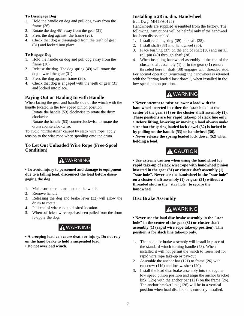
To Disengage Dog1. Hold the handle on dog and pull dog away from the
frame (26).2. Rotate the dog 45° away from the gear (31).3. Press the dog against the frame (26).4. Check that dog is disengaged from the teeth of gear
(31) and locked into place.
To Engage Dog1. Hold the handle on dog and pull dog away from the
frame (26).2. Release the dog. The dog spring (49) will rotate the
dog toward the gear (31).3. Press the dog against frame (26).4. Check that dog is engaged with the teeth of gear (31)
and locked into place.
Paying Out or Hauling In with HandleWhen facing the gear and handle side of the winch with thehandle located in the low speed pinion position:
Rotate the handle (53) clockwise to rotate the drumclockwise.Rotate the handle (53) counterclockwise to rotate thedrum counterclockwise.
To avoid “birdnesting” caused by slack wire rope, applytension to the wire rope when spooling onto the drum.
To Let Out Unloaded Wire Rope (Free-SpoolCondition)
• To avoid injury to personnel and damage to equipmentdue to a falling load, disconnect the load before disen-gaging the dog.
1. Make sure there is no load on the winch.2. Remove handle.3. Releasing the dog and brake lever (32) will allow the
drum to rotate.4. Pull end of wire rope to desired location.5. When sufficient wire rope has been pulled from the drum
re-apply the dog.
• A creeping load can cause death or injury. Do not relyon the hand brake to hold a suspended load.• Do not overload winch.
Installing a 28 in. dia. Handwheel(ref. Dwg. MHTPA0125)Handwheels are supplied assembled from the factory. Thefollowing instructions will be helpful only if the handweelhas been disassembled.1. Install retaining ring (39) on shaft (38).2. Install shaft (38) into handwheel (36).3. Place bushing (37) on the end of shaft (38) and install
roll pin (40) through shaft (38).4. When installing handwheel assembly in the end of the
cluster shaft assembly (1) or in the gear (31) ensurethreaded bore in shaft (38) engages with threaded stud.
For normal operation (winching) the handwheel is retainedwith the "spring loaded lock dowel", when installed in thelow-speed pinion position.
• Never attempt to raise or lower a load with thehandwheel inserted in either the "star hole" at thecenter of the gear (31) or the cluster shaft assembly (1).These positions are for rapid take-up of slack line only.• Before lifting, lowering or moving a load always makesure that the spring loaded lock dowel (52) is locked inby pulling on the handle (53) or handwheel (36).• Never release the spring loaded lock dowel (52) whenholding a load.
• Use extreme caution when using the handwheel forrapid take-up of slack wire rope with handwheel pinioninserted in the gear (31) or cluster shaft assembly (1)"star hole". Never use the handwheel in the "star hole"on a cluster shaft assembly (1) or gear (31) without athreaded stud in the "star hole" to secure thehandwheel.
Disc Brake Assembly
• Never use the load disc brake assembly in the "starhole" in the center of the gear (31) or cluster shaftassembly (1) (rapid wire rope take-up position). Thisposition is for slack line take-up only.
1. The load disc brake assembly will install in place ofthe standard winch turning handle (53). Wheninstalled it will not permit the winch to freewheel forrapid wire rope take-up or pay-out.
2. Assemble the anchor bar (121) to frame (26) withcapscrew (119) and lockwasher (120).
3. Install the load disc brake assembly into the regularlow speed pinion position and align the anchor bracketlink (126) with the anchor bar (121) on the frame (26).The anchor bracket link (126) will be in a verticalposition when load disc brake is correctly installed.
7
WARNING
WARNING
WARNING
CAUTION
WARNING

8
4. When load disc brake is correctly positioned install thecotter pin (123) through the anchor bar (121) to securethe load disc brake assembly.
5. Check that the load disc brake assembly is fully lockedin place by the spring loaded lock dowel (52). Checkthat spring loaded lock dowel is engaged by pulling onthe handle.
6. To adjust handle length loosen lockscrew (56), sethandle (53) to required position then tighten lockscrew(56).
7. To take-up wire rope rotate handle in a clockwisedirection. This causes the actuating screw (107) toclamp the friction discs (105) against the ratchet wheel(106). Continued turning of the handle will disengagethe ratchet dog (113) and allow the ratchet wheel (106)to turn. An audible clicking will be noticed as eachtooth on the ratchet wheel rotates past the ratchet dogand the ratchet dog spring (112) causes the ratchet dogto engage the next tooth.
8. To payout wire rope rotate handle in a counterclock-wise direction. This will rotate the actuating screw(107) to release the friction discs (105) from theratchet wheel (106) which is held stationary by theratchet dog. When handle rotation ceases, tension onthe wire rope will tighten the actuating screw (107) toclamp the friction discs (105) and hold the load.
• The load disc brake assembly requires no adjustment.
NOTICE

3. DRUM. Check for cracks, wear or damage. Replace orrepair if necessary.
4. ALL COMPONENTS. Inspect for wear, damage,distortion and cleanliness. If external evidence indi-cates the need, for example poor performance orexcessive noise, disassemble and inspect. Check pins,gears, shafts, bushings, sheaves, covers, etc. Replaceworn or damaged parts.
5. BRAKE. Check the thickness of the brake shoe lining.Replace the brake shoe if the lining is less than.062 in. (2 mm) thick anywhere along its edge. Checkability of brake to hold rated load. Adjust brake asrequired. Refer to brake adjustment procedures in"MAINTENANCE" section.
6. SUPPORTING STRUCTURE. Check for distortion,wear and continued ability to support the winch andload.
7. LABELS AND TAGS. Check for presence andlegibility. Replace if necessary.
8. WIRE ROPE. Besides the items in a frequent inspec-tion, inspect for the following:a. Loose or damaged connections to wire rope. Check
for build-up of dirt and corrosion. Clean ifnecessary. Make sure the wire rope anchor screwis tight and check for signs of slippage of the wirerope end. If slippage is evident, reinstall per wirerope anchor installation procedure.
b. Check for changes in the size of the wire ropediameter. Measure the diameter from crown-to-crown. (See Dwg. MHTPA0056). If the nominaldiameter of the wire rope has decreased more than1/64 in. (0.4 mm), replace the wire rope.
(Dwg. MHTPA0056)
• Never use a winch that inspection indicates is defec-tive.
There are two types of inspection, the frequent inspectionperformed by the operator and more thorough periodicinspections performed by qualified personnel.
Frequent InspectionOn winches in continuous service, frequent inspectionshould be made at the beginning of each shift. In addition,visual observations should be conducted during regularservice for any damage or evidence of malfunction.1. OPERATION. To make sure the drive mechanism
operates properly, check for sticking or other signs ofmalfunction. Repair if necessary. Test brake operationby lifting a load 1 to 2 in. (25 to 50 mm) off the floorand check that the brake holds the load.
2. LIMIT DEVICES. If used, check that they operateproperly.
3. WIRE ROPE. Lubricate if necessary. Replace the wirerope if damaged or excessively worn. Consult the wirerope manufacturer’s inspection information or arecognized safety source, such as the latest edition ofNational Safety Council, Accident Prevention Manualfor Industrial Operations or ANSI/ASME B30.7. Thefollowing list is a users guide to the accepted standardsby which wire rope must be judged and is not pre-sented as a substitute for an experienced inspector.a. Damage, such as: bird cages, kinking, core
protrusion, crushing, heat damage, and mainstrand displacement.
b. Corrosion, nicking and wear of crown wires.c. Wear of crown wires. Replace at 1/3 wear of the
original diameter of any crown wire.d. Broken wires or strands, particularly at connec-
tions. Replacement is necessary if one wire isbroken at a connection; six broken wires withinone lay; three broken wires in one strand withinone lay.
4. WIRE ROPE REEVING. Check reeving and ensurewire rope is properly secured to the drum.
Periodic InspectionAccording to ANSI/ASME B30.7, frequency of periodicinspection depends on the severity of usage: NORMAL,yearly; HEAVY, semi-annually; SEVERE, quarterly.Disassembly may be required for HEAVY or SEVEREusage. Keep accumulative records of periodic inspections toprovide a basis for continuing evaluation.
Inspect all items in “Frequent Inspection” also inspect thefollowing:1. MEMBERS. Check for deformed, cracked or corroded
main components. Replace damaged parts if necessary.2. FASTENERS. Check rivets, cotter pins, capscrews and
nuts on winch, including mounting bolts. Replace ifmissing and tighten if loose.
INSPECTION
9
CROWNTO
CROWN
WARNING

10
• Lubricate the winch regularly using only the recom-mended lubricants.
GearsIf winch is disassembled, clean all parts thoroughly andcoat gears with clean grease. Lubricate working surfaces ofall gear teeth. Brush with grease as often as necessary tokeep the teeth liberally covered. If the grease becomescontaminated with sand, dirt or other abrasive materialsclean off old grease and relubricate. For temperatures -20°
to 50° F (-29° to 10° C) use a multipurpose lithium-basedEP 1 grease. For temperatures 30° to 120° F (-1° to 49° C)use a multipurpose lithium-based EP 2 grease.
Pivot Points and BushingsLubricate all grease fittings monthly with 2 or 3 pumpsfrom a grease gun, or more frequently, depending onseverity of service. Rotate drum and gearing slowly asgrease is applied. Use the same grease recommended forthe gears.
Wire RopeFollow the wire rope manufacturer’s instructions. At aminimum, observe the following guidelines.
• Do not use an acid-based solvent. Only use cleaningfluids specified by the wire rope manufacturer.
1. If there is dirt, rock dust or other foreign material onthe surface of the rope, clean with a brush or steam.
2. Apply a wire rope lubricant or SAE 30 W oil.3. Brush, drip or spray lubricant weekly, or more fre-
quently, depending on severity of service.
LUBRICATION
CAUTION
Winches Not in Regular UseA winch which has been idle for a period of one month ormore, but less than six months, shall be given an inspectionconforming with the requirements of "Frequent Inspection"before being placed into service.
A winch which has been idle for a period of over sixmonths shall be given a complete inspection conformingwith the requirements of "Periodic Inspection". Standbywinches shall be inspected at least semi-annually inaccordance with the requirements of "Frequent Inspection".If adnormal operating conditions apply winches mayrequire a more frequent inspection.
TestingOperational TestsPrior to initial use, all new, altered or repaired winchesshall be tested to ensure proper operation.1. Operate winch in both directions with no load.2. Check operation of brake and dogs.3. Check operation of limit switches, and locking or
safety devices when provided.4. Check all tie-downs are secure.
Rated Load TestPrior to initial use, all new, extensively reparied, or alteredwinches shall be tested by or under the direction of aqualified person, and a written report furnished confirmingthe rating of the winch. Test loads shall not be more than110% of the rated line pull.
CAUTION

• Never perform adjustments or maintenance on thewinch while it is supporting a load.• Before performing maintenance, tag winch handle:DANGER - DO NOT OPERATE - EQUIPMENTBEING REPAIRED.• Only allow qualified service personnel to performmaintenance.• After performing any maintenance on the winch, testwinch to 110% of its rated capacity before returning toservice.
Make sure that all parts are in place and operatingcorrectly. Replace worn or missing parts with genuineWINTECH INTERNATIONAL factory replacement parts.
BrakeAdjustment (ref. Dwg. MHTPA0127)1. Remove cotter pin (43) and dowel (42). Pull out gear
(31).2. Loosen nut (29) and adjusting screw (28).3. Tighten adjusting screw (28) to increase brake
torque.4. Lock adjusting screw (28) with nut (29).5. Replace gear (31). Secure in position with dowel (42).
Install cotter pin (43) through frame (26) and dowel(42).
6. Brake is adjusted properly when drum is locked withbrake lever (32) approximately 1.0 in. (25 mm) awayfrom the stop. Drum should turn freely when brakelever is against stop and dog is disengaged.
• Brake shoe (34) should be replaced if lining is less than.062 in. (2 mm) thick anywhere along its edge.
(Dwg. MHTPA0127)
General DisassemblyThe following instructions provide the necessaryinformation to disassemble, inspect, repair, and assemblethe winch. An exploded drawing of the winch is providedin the Parts Section to assist part identification.If a winch is being completely disassembled for any reason,follow the order of the topics as they are presented. It isrecommended that all maintenance work on the winch beperformed in a clean and spacious work area.In the process of disassembling the winch, observe thefollowing:1. Never disassemble the winch any further than is
necessary to accomplish the needed repair. A good partcan be damaged during the course of disassembly.
2. Never use excessive force when removing parts.Tapping gently around the perimeter of a part with asoft hammer should be sufficient to loosen the part.
3. Do not heat a part with a torch to free it for removal,unless the part being heated is already worn ordamaged beyond repair.
In general, the winch is designed to permit easydisassembly and assembly. The use of heat or excessiveforce should not be required.
4. When grasping a part in a vise, always use leather-covered or copper-covered vise jaws to protect thesurface of the part and help prevent distortion. This isparticularly true of threaded members and shafts.
5. Do not remove any part which is press fit in or on asubassembly unless the removal of that part isnecessary for repairs or replacement.
Winch DisassemblyModel R Winch(ref. dwg. MHTPB0147)1. Remove the wire rope from the drum (6).2. Remove the winch from its mounting and set in a clean
work area.3. Remove drum gear guard (7) if equipped.4. Remove capscrews (10), lockwashers (12), nuts (13)
and spacer washers (11). Note position and quantity ofspacer washers for reassembly.
5. Unhook dog spring (49) from large dog (21).6. Support the weight of the cluster shaft assembly (1)
and remove the assembled frame (26) and set to oneside for later disassembly.
7. Slide cluster shaft assembly (1) from frame (19).8. Remove setscrews (14) and (22) in frame (19).9. Pull large dog (21) and dog pin (20) from the end of
drum shaft (18).10. Using an overhead hoist support the weight of the
drum (6) and drive out drum shaft (18). Care must betaken to avoid damage to the pins located in the end ofthe drum shaft.
11
WARNING
MAINTENANCE
CAUTION
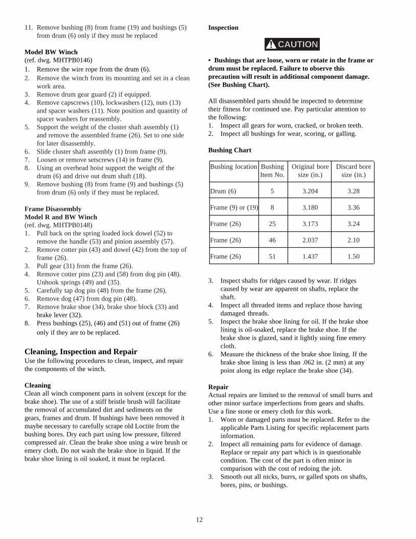
Inspection
• Bushings that are loose, worn or rotate in the frame ordrum must be replaced. Failure to observe thisprecaution will result in additional component damage.(See Bushing Chart).
All disassembled parts should be inspected to determinetheir fitness for continued use. Pay particular attention tothe following:1. Inspect all gears for worn, cracked, or broken teeth.2. Inspect all bushings for wear, scoring, or galling.
Bushing Chart
3. Inspect shafts for ridges caused by wear. If ridgescaused by wear are apparent on shafts, replace theshaft.
4. Inspect all threaded items and replace those havingdamaged threads.
5. Inspect the brake shoe lining for oil. If the brake shoelining is oil-soaked, replace the brake shoe. If thebrake shoe is glazed, sand it lightly using fine emerycloth.
6. Measure the thickness of the brake shoe lining. If thebrake shoe lining is less than .062 in. (2 mm) at anypoint along its edge replace the brake shoe (34).
RepairActual repairs are limited to the removal of small burrs andother minor surface imperfections from gears and shafts.Use a fine stone or emery cloth for this work.1. Worn or damaged parts must be replaced. Refer to the
applicable Parts Listing for specific replacement partsinformation.
2. Inspect all remaining parts for evidence of damage.Replace or repair any part which is in questionablecondition. The cost of the part is often minor incomparison with the cost of redoing the job.
3. Smooth out all nicks, burrs, or galled spots on shafts,bores, pins, or bushings.
12
CAUTION
11. Remove bushing (8) from frame (19) and bushings (5)from drum (6) only if they must be replaced
Model BW Winch(ref. dwg. MHTPB0146)1. Remove the wire rope from the drum (6).2. Remove the winch from its mounting and set in a clean
work area.3. Remove drum gear guard (2) if equipped.4. Remove capscrews (10), lockwashers (12), nuts (13)
and spacer washers (11). Note position and quantity ofspacer washers for reassembly.
5. Support the weight of the cluster shaft assembly (1)and remove the assembled frame (26). Set to one sidefor later disassembly.
6. Slide cluster shaft assembly (1) from frame (9).7. Loosen or remove setscrews (14) in frame (9).8. Using an overhead hoist support the weight of the
drum (6) and drive out drum shaft (18).9. Remove bushing (8) from frame (9) and bushings (5)
from drum (6) only if they must be replaced.
Frame DisassemblyModel R and BW Winch(ref. dwg. MHTPB0148)1. Pull back on the spring loaded lock dowel (52) to
remove the handle (53) and pinion assembly (57).2. Remove cotter pin (43) and dowel (42) from the top of
frame (26).3. Pull gear (31) from the frame (26).4. Remove cotter pins (23) and (58) from dog pin (48).
Unhook springs (49) and (35).5. Carefully tap dog pin (48) from the frame (26).6. Remove dog (47) from dog pin (48).7. Remove brake shoe (34), brake shoe block (33) and
brake lever (32).8. Press bushings (25), (46) and (51) out of frame (26)
only if they are to be replaced.
Cleaning, Inspection and RepairUse the following procedures to clean, inspect, and repairthe components of the winch.
CleaningClean all winch component parts in solvent (except for thebrake shoe). The use of a stiff bristle brush will facilitatethe removal of accumulated dirt and sediments on thegears, frames and drum. If bushings have been removed itmaybe necessary to carefully scrape old Loctite from thebushing bores. Dry each part using low pressure, filteredcompressed air. Clean the brake shoe using a wire brush oremery cloth. Do not wash the brake shoe in liquid. If thebrake shoe lining is oil soaked, it must be replaced.
Bushing location
Drum (6)
Frame (9) or (19)
Frame (26)
Frame (26)
Frame (26)
Discard boresize (in.)
3.28
3.36
3.24
2.10
1.50
Original boresize (in.)
3.204
3.180
3.173
2.037
1.437
BushingItem No.
5
8
25
46
51

13
4. Examine all gear teeth carefully, and remove nicks orburrs.
5. Polish the edges of all shaft shoulders to remove smallnicks which may have been caused during handling.
6. Remove all nicks and burrs caused by lockwashers.
Winch AssemblyFrame AssemblyModel R and BW Winch(ref. dwg. MHTPB0148)1. Press new bushings (25), (46) and (51) into frame (26)
so they are 1/16 in. (2 mm) below the outer surface ofthe frame. Check bores to ensure bushings do notrestrict the grease fitting passages. If needed drill a 1/8in. (3 mm) diameter hole through the bushing toprovide a grease passage. Use existing grease fittinghole in frame as a guide. Install grease fittings (41) inframe (26).
2. Slide dog (47) onto dog pin (48). Align cotter pin holein dog pin (48) with hole in frame (26) and tap dog pininto frame. Install cotter pin (23). If a new dog pin isbeing used it will be necessary to drill a 3/16 in. (5mm) diameter hole through the dog pin using the holein the frame as a guide.
3. Connect spring (49) between dog (47) and frame.4. Install setscrew (28) and nut (29) in brake shoe block
(33). Assemble brake lever (32), brake shoe block (33)and brake shoe to frame (26) so the pivot hole in thebrake shoe fits on the dog pin (48). Secure in positionwith cotter pin (58).
5. Connect spring (35) from brake shoe (34) to frame(26). Install spring loaded lock dowel (52) in largeframe (26) and secure with cotter pin (43). Cotter pin(43) must pass through slot and between spring coils inthe spring loaded lock dowel (52).
• The flat of the 90 degree cut out in the spring loadedlock dowel (52) must face toward the drum.
6. Install gear (31) in frame (26). Install dowel (42) sothe flat of the 90° cut out faces toward the drum.Secure in position with cotter pin (43).
7. Check movement of dog (47) and that it freely clicksinto position against the teeth on the gear (31).
8. Adjust brake shoe in accordance with instructions fordrum brake adjustment in the "MAINTENANCE"section.
9. Install pinion (57) in frame (26). Ensure the springloaded lock dowel (52) is fully engaged in the pinionshaft groove.
10. Lubricate all grease fittings as instructed in the"LUBRICATION" section.
11. Install handle (53) through the slot in the pinion (57),adjust to the required length and clamp in positionwith lockscrew (56). Install handle retainer capscrew(54) and nut (55) in the end of handle (53).
Model R Winch(ref. dwg. MHTPB0147)1. Press new bushings (5) into the drum (6) if they are
being replaced. Install bushings (5) so lubrication holelines up with grease fitting hole in drum. Check drumshaft (18) slides into bushings (5) without binding.
2. Using an overhead hoist position the drum (6) in frame(19) and install drum shaft (18) through drum andframe. Install drum shaft (18) so the end with thedrilled hole is on the side where frame (26) will mount.
3. Rotate drum shaft (18) to align locating hole withsetscrew (22). If a new drum shaft is being installeduse the setscrew hole in frame (19) as a guide to markthe position of locating hole. Remove drum shaft. Drillone 0.781 in. (20 mm) diameter hole deep enough forit to fully break through into the cross hole. Reinstallthe drum shaft.
4. Install dog (21) on dog pin (20) and press dog pin intothe end of drum shaft (18). Lock drum shaft (18) anddog pin (20) in position with setscrew (22). Tightensetscrews (22) and (14) and locknuts (15). Connect dogspring (49).
5. Press new bushing (8) into frame (19) if it is beingreplaced. Check bore to ensure bushing does notrestrict the grease fitting passage. If needed drill a1/8 in. (3 mm) diameter hole through the bushing toprovide a grease passage. Use existing grease fittinghole in frame as a guide. Install grease fittings (41) inframe (19).
6. Install cluster shaft assembly (1) in frame (19).7. Support cluster shaft assembly (1) and install pre-
assembled frame (26).8. Secure in position with capscrews (10), lockwashers
(12), nuts (13) and spacer washers (11). Positionspacer washers as noted on disassembly. Check clustershaft assembly and gear rotate freely and do notinterfere with frame. Adjust spacer washers (11) toprovide correct clearance.
9. Install drum guard (7) if equipped.
Model BW Winch(ref. dwg. MHTPB0146)1. Press new bushings (5) into the drum (6) if they are
being replaced. Install bushings (5) so lubrication holelines up with grease fitting hole in drum. Check drumshaft (18) slides into bushings without binding.
2. Using an overhead hoist position the drum (6) in frame(9) and install drum shaft (18) through drum (6) andframe (9).
3. Lock drum shaft in position with setscrews (14).Tighten locknuts (15).
4. Press new bushing (8) into frame (9) if it is being
CAUTION

14
The use of replacement parts other thanWINTECH INTERNATIONAL parts will invalidate theCompany’s warranty. For prompt service and genuineWINTECH INTERNATIONAL parts, provide your nearestDistributor with the following:1. Complete model number: R10/R10W, R14/R14W,
BW10/BW10W or BW14/BW14W.2. Part number and part description as shown in this
manual.3. Quantity required.
PARTS ORDERING INFORMATION
Return Goods PolicyWINTECH Interna-
• Continuing improvement and advancement of designmay cause changes to this winch which are not includedin this manual. Manuals are periodically revised toincorporate changes. Always check the manual editionnumber on the front cover for the latest issue.
NOTICE
replaced. Check cluster gear shaft (1) slides intobushing (8) without binding. Check bore to ensurebushing does not restrict the grease fitting passage. Ifneeded drill a 1/8 in. (3 mm) diameter hole throughthe bushing to provide a grease passage. Use existinggrease fitting hole in frame as a guide. Install greasefittings (41) in frame (9).
5. Install cluster shaft assembly (1) in frame (9).6. Support cluster shaft assembly (1) and install pre-
assembled frame (26).7. Secure in position with capscrews (10), lockwashers
(12), nuts (13) and spacer washers (11). Positionspacer washers as noted on disassembly.
8. Install drum guard (2) if equipped.
Test CheckCheck that all warning labels and tags are attached to thewinch and clearly visible. Inspect guards for properinstallation. Check all fasteners are secure.Upon completion of all winch maintenance and repairscheck winch operation following procedures in the"INSTALLATION" section.

15
R WINCH ASSEMBLY DRAWING
(Dwg. MHTPB0147)
4 1
1
4
3
4 1
5
7
5
6
2 02 1
4 92 2
1 51 0
1 1
1 4
1 5
1 8
4 1
8
1 0
1 91 2
1 3
1 3
1 2
1 1
1 6
1 7

16
BW WINCH ASSEMBLY DRAWING
(Dwg. MHTPB0146)
4 1
1
2
34
4 1
5
6
4 1
8
1 51 4
5
1 8
1 01 1
1 21 3
1 7
1 61 2
1 3
1 0
1 4
1 5
9

17
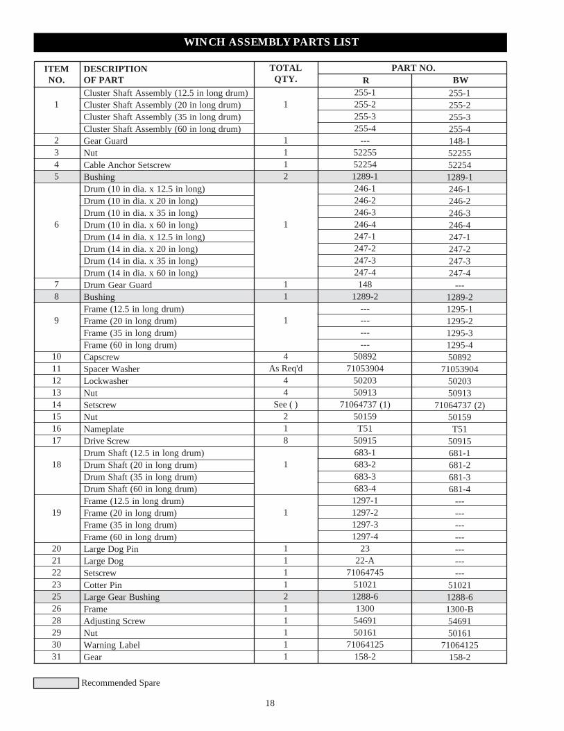
R AND BW WINCH ASSEMBLY DRAWING
18
ITEMNO.
TOTALQTY.
1
1112
1
11
1
4As Req'd
44
See ( )218
1
1
1111211111
255-1255-2255-3255-4
---52255522541289-1246-1246-2246-3246-4247-1247-2247-3247-4148
1289-2------------
5089271053904
5020350913
71064737 (1)50159T51
50915683-1683-2683-3683-4
1297-11297-21297-31297-4
2322-A
71064745510211288-61300
5469150161
71064125158-2
255-1255-2255-3255-4148-152255522541289-1246-1246-2246-3246-4247-1247-2247-3247-4
---1289-21295-11295-21295-31295-450892
710539045020350913
71064737 (2)50159T51
50915681-1681-2681-3681-4
---------------------
510211288-61300-B5469150161
71064125158-2
DESCRIPTIONOF PART
PART NO.R BW
Recommended Spare
Cluster Shaft Assembly (12.5 in long drum)Cluster Shaft Assembly (20 in long drum)Cluster Shaft Assembly (35 in long drum)Cluster Shaft Assembly (60 in long drum)Gear GuardNutCable Anchor SetscrewBushingDrum (10 in dia. x 12.5 in long)Drum (10 in dia. x 20 in long)Drum (10 in dia. x 35 in long)Drum (10 in dia. x 60 in long)Drum (14 in dia. x 12.5 in long)Drum (14 in dia. x 20 in long)Drum (14 in dia. x 35 in long)Drum (14 in dia. x 60 in long)Drum Gear GuardBushingFrame (12.5 in long drum)Frame (20 in long drum)Frame (35 in long drum)Frame (60 in long drum)CapscrewSpacer WasherLockwasherNutSetscrewNutNameplateDrive ScrewDrum Shaft (12.5 in long drum)Drum Shaft (20 in long drum)Drum Shaft (35 in long drum)Drum Shaft (60 in long drum)Frame (12.5 in long drum)Frame (20 in long drum)Frame (35 in long drum)Frame (60 in long drum)Large Dog PinLarge DogSetscrewCotter PinLarge Gear BushingFrameAdjusting ScrewNutWarning LabelGear
WINCH ASSEMBLY PARTS LIST
1
2345
6
78
9
1011121314151617
18
19
20212223252628293031

WINCH ASSEMBLY PARTS LIST
19
ITEMNO.
TOTALQTY.
1111
See ( )12111112121111111111
1307937
22031352
53839 (8)290-B5416550040710564101288-5
391353
509181288-4
303286
5285653541
239165B54447
---249---
DESCRIPTIONOF PART
PART NO.R BW
1307937
22031352
53839 (7)290-B5416550040710564101288-5
391353
509181288-4
303286
5285653541
239165B54447
367249
Brake LeverBrake Shoe BlockBrake ShoeBrake SpringGrease FittingDowelCotter PinLabel RingWarning TagCluster Shaft BushingDogDog PinDog SpringSpacer WasherPinion BushingSpring Loaded Lock DowelHandleCapscrewNutLockscrewPinionCotter PinReverse DogGear GuardReverse Dog Bracket
DESCRIPTIONOF PART
Pinion and Handle Assembly(Incl's items 53 thru 57)Brake Assembly(Incl's items 28, 29 and 32 thru 35)Dog Assembly(Incl's items 41, 47 thru 50 and 58)Load Disc Brake Assembly(Incl's items 53, 56 and 100 thru 126)
Recommended Spare
32333435414243444546474849505152535455565758606162
Not sold separately
ASSEMBLIES
289
796
795
3677
289
796
795
3677
PART NO.
Not sold separately
R BW

LOAD DISC BRAKE ASSEMBLY PARTS LIST
20
PART NO.
11122111211
111
1111
Load Disc Brake AssemblyHandleLockscrewHousing PlateNutHousing CylinderPinFlange Head PinionFriction DiscRatchet WheelActuating ScrewActuating Screw (Reverse Dog)PinRetainer BushingActuating Flange NutActuating Flange Nut (Reverse Dog)SetscrewRatchet Dog SpringRatchet DogSpacer Sleeve
5356
100101102103104105106107
108109110
111112113114
3677286239
199951682199839812005220721781992
1992-12046619932004
2004-15085520021996
1996-1
ITEMNO.
DESCRIPTIONOF PART
TOTALQTY.
(Dwg. MHTPA0163)
1 0 6
1 0 5
1 0 41 0 3
1 0 2
1 0 01 0 1
1 2 2
1 0 5
1 0 71 0 8
1 0 9
1 1 0
1 1 2
1 1 3
1 1 4
1 0 0
1 1 5
1 1 6
1 1 7
5 6
1 1 8
5 3
1 2 2
1 2 6
1 2 31 2 1
1 2 51 1 1
1 2 4
1 2 01 1 9

21
* Used only with optional handwheel item 36.
PART NO.
2111111211211
CapscrewSetscrewNutHandle SocketCapscrewLockwasherAnchor BarLink NutCotter PinHousing Anchor StudSpacer SleeveAnchor Bracket LinkHandwheel 28 in. Dia. (Optional)
115116117118119120121122123124125126
127*
5283154173501981990
7106876171027734
22062199
5102120465199721933628
ITEMNO.
DESCRIPTIONOF PART
TOTALQTY.
ITEMNO.
DESCRIPTIONOF PART
TOTALQTY.
3136
37*38*39*40*
GearHandwheel 28 in. dia. (Optional)BushingShaftRetainer RingPin
158-HM1580-1
778780
7103893971038947
PART NO.
111111
(Dwg. MHTPA0125)
R AND BW HANDWHEEL ASSEMBLY
* Not Shown. Handwheel replaces items 53, 56 and 118 when used.

SERVICE NOTES
22

HOIST AND WINCH LIMITED WARRANTY
Wintech International warrants to the originaluser its Hoists and Winches (Products) to be freeof defects in material and workmanship for aperiod of one year from the date of purchase.Wintech will repair, without cost, any Product foundto be defective, including parts and labor charges,or at its option, will replace such Products orrefund the purchase price less a reasonableallowance for depreciation, in exchange for theProduct. Repairs or replacements are warranted forthe remainder of the original warranty period.
If any Product proves defective within its originalone year warranty period, it should be returned toany Authorized Hoist and Winch Service Distribu-tor, transportation prepaid with proof of purchaseor warranty card.
This warranty does not apply to Products whichWintech has determined to have been misused orabused, improperly maintained by the user, orwhere the malfunction or defect can be attributedto the use of non-genuine Wintech parts.
It is our policy to promote safe delivery of allorders.This shipment has been thoroughly checked,packed and inspected before leaving our plant andreceipt for it in good condition has been receivedfrom the carrier. Any loss or damage which occursto this shipment while enroute is not due to anyaction or conduct of the manufacturer.
VISIBLE LOSS OR DAMAGEIf any of the goods called for on the bill of ladingor express receipt are damaged or the quantity isshort, do not accept them until the freight orexpress agent makes an appropriate notation onyour freight bill or express receipt.
CONCEALED LOSS OR DAMAGEWhen a shipment has been delivered to you in
IMPORTANT NOTICE
WARRANTY
Wintech makes no other warranty, and all impliedwarranties including any warranty ofmerchantability or fitness for a particularpurpose are limited to the duration of theexpressed warranty period as set forth above.Wintech’s maximum liability is limited to thepurchase price of the Product and in no eventshall Wintech be liable for any consequential,indirect, incidental, or special damages of anynature rising from the sale or use of the Prod-uct, whether based on contract, tort, or other-wise.
Note: Some states do not allow limitations onincidental or consequential damages or how longan implied warranty lasts so that the abovelimitations may not apply to you.
This warranty gives you specific legal rights andyou may also have other rights which may varyfrom state to state.
apparent good condition, but upon opening thecrate or container, loss or damage has taken placewhile in transit, notify the carrier’s agent immedi-ately.
DAMAGE CLAIMSYou must file claims for damage with the carrier. Itis the transportation company’s responsibility toreimburse you for repair or replacement of goodsdamaged in shipment. Claims for loss or damage inshipment must not be deducted from theWintech International invoice, nor should payment ofWintech International invoice be withheld awaitingadjustment of such claims as the carrier guaranteessafe delivery.You may return products damaged in shipment tous for repair, which services will be for youraccount and form your basis for claim against thecarrier.
23

Printed in USA
For Order Entry, Order Status, and Technical Support: Wintech International, L.L.C. 5319 Shreveport/Blanchard Hwy. Shreveport, LA. 71107 Phone: (318) 929-1242 1-888-946-8325 Fax: (318) 929-1245 www.wintech-winches.com
United States Office Location