hammond drawbar assembly servicing clifford rote 10/23/2006 revised 10/18/2008
TRANSCRIPT
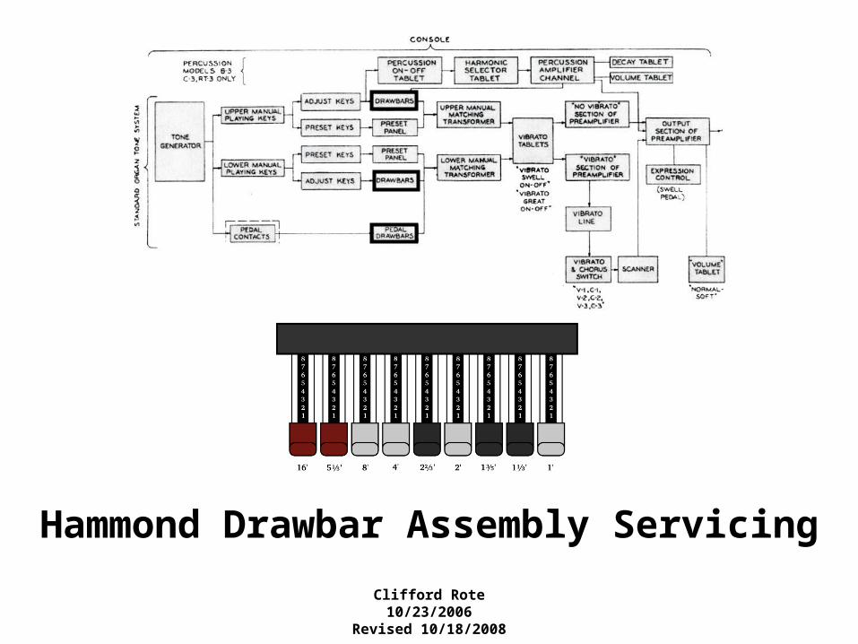
Hammond Drawbar Assembly Servicing
Clifford Rote10/23/2006
Revised 10/18/2008

1
1
2 3 4 5 6 7 8 9 10 11 12 13 14 15 16 17 18 19 20 21 22 23 24 25 26 27 28 29 30 31 32 33 34 35 36 37 38 39
1 2 3 4 5 6 7 8 9 10 11 12 13 14 15 16 17 18 19 20 21 22 23 24 25 26 27 28 29 30 31 32 33 34 35 36 37 38 39
Left-rear row of screws
Left-front row of screws
1. Drawbar clamshell fasteners viewed from above
Drawbar Assembly Components
n 6-32 x 1” screws with lock washers on TOP of clamshell. These pass THRU clamshell to screw into drawbar desk to attach clamshell to the desk.
n 6-32 x 1” screws with lock washers and nuts on BOTTOM of clamshell. These attach top of clamshell to bottom of clamshell with spacers in between.
Pedal DBSection
6-32 x 1½” screw passes through drawbar desk to screw into Chorus-Vibrato switch assembly located under desk. (A105)
2. Drawbar bus wire colorsBlack,Brown
RedOrangeYellowGreen
BlueVioletGrey
Black,BrownRedOrangeYellowGreenBlueVioletGrey
Clamshell
Left-front
Left-rear Right-rear
Right-front
3. Drawbar specifications
DB # 1 2 3 4 5 6 7 8 9 ------Pedals------
Footage 16’ 51/3’ 8’ 4’ 22/3’ 2’ 13/5’ 11/3’ 1’ 16’ 8’
Wire Color brown red orange yellow green blue violet grey white brown red
Knob Color brown brown white white black white black black white brown brown
This page drawn and annotated by C. Rote
Upper Manual DB Bus Bars
on Left
Lower Manual & Pedal DB Bus Bars on Right
4. Drawbar clamshell front and rear spacers
Upper Manual-A# Upper Manual-B Lower Manual-A# Lower Manual-BPedals
Rear Spacer openings to accommodate both the drawbar and the spring-contact
are larger than Front Spacer openings
Bottom
Top
#2-Rear is longer to accommodate the bus wire bracket
#38-Rear is longer to accommodate the bus wire bracket
Alignment posts have a lock washer and nut on bottom of clamshell.
Alignment posts only on older organs up to early 1960s
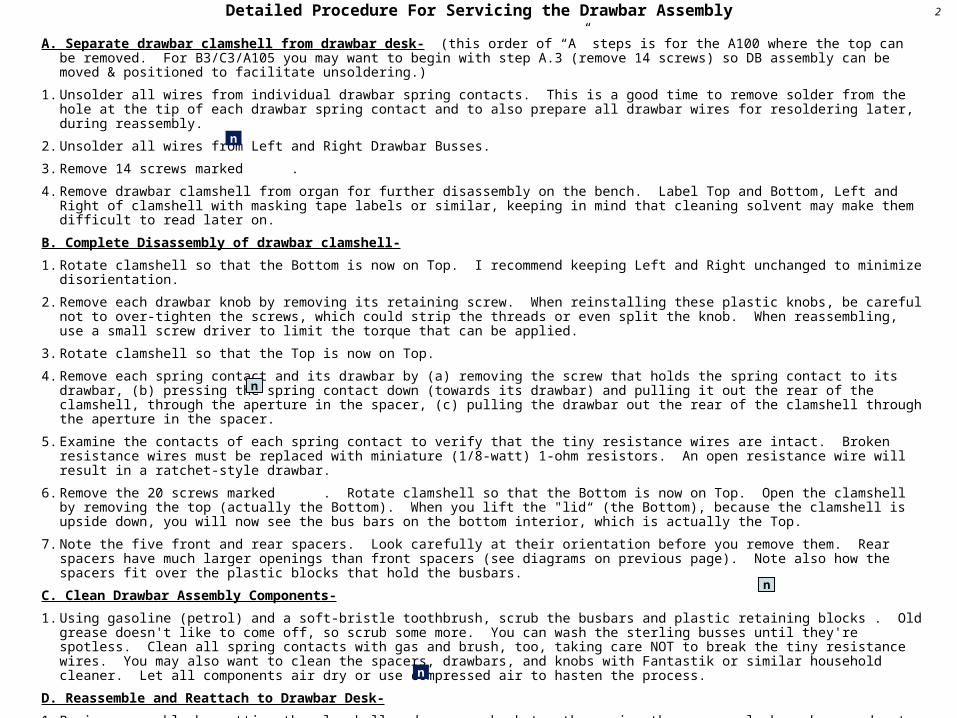
A. Separate drawbar clamshell from drawbar desk- (this order of “A” steps is for the A100 where the top can be removed. For B3/C3/A105 you may want to begin with step A.3 (remove 14 screws) so DB assembly can be moved & positioned to facilitate unsoldering.)
1. Unsolder all wires from individual drawbar spring contacts. This is a good time to remove solder from the hole at the tip of each drawbar spring contact and to also prepare all drawbar wires for resoldering later, during reassembly.
2. Unsolder all wires from Left and Right Drawbar Busses.
3. Remove 14 screws marked .
4. Remove drawbar clamshell from organ for further disassembly on the bench. Label Top and Bottom, Left and Right of clamshell with masking tape labels or similar, keeping in mind that cleaning solvent may make them difficult to read later on.
B. Complete Disassembly of drawbar clamshell-
1. Rotate clamshell so that the Bottom is now on Top. I recommend keeping Left and Right unchanged to minimize disorientation.
2. Remove each drawbar knob by removing its retaining screw. When reinstalling these plastic knobs, be careful not to over-tighten the screws, which could strip the threads or even split the knob. When reassembling, use a small screw driver to limit the torque that can be applied.
3. Rotate clamshell so that the Top is now on Top.
4. Remove each spring contact and its drawbar by (a) removing the screw that holds the spring contact to its drawbar, (b) pressing the spring contact down (towards its drawbar) and pulling it out the rear of the clamshell, through the aperture in the spacer, (c) pulling the drawbar out the rear of the clamshell through the aperture in the spacer.
5. Examine the contacts of each spring contact to verify that the tiny resistance wires are intact. Broken resistance wires must be replaced with miniature (1/8-watt) 1-ohm resistors. An open resistance wire will result in a ratchet-style drawbar.
6. Remove the 20 screws marked . Rotate clamshell so that the Bottom is now on Top. Open the clamshell by removing the top (actually the Bottom). When you lift the "lid“ (the Bottom), because the clamshell is upside down, you will now see the bus bars on the bottom interior, which is actually the Top.
7. Note the five front and rear spacers. Look carefully at their orientation before you remove them. Rear spacers have much larger openings than front spacers (see diagrams on previous page). Note also how the spacers fit over the plastic blocks that hold the busbars.
C. Clean Drawbar Assembly Components-
1. Using gasoline (petrol) and a soft-bristle toothbrush, scrub the busbars and plastic retaining blocks . Old grease doesn't like to come off, so scrub some more. You can wash the sterling busses until they're spotless. Clean all spring contacts with gas and brush, too, taking care NOT to break the tiny resistance wires. You may also want to clean the spacers, drawbars, and knobs with Fantastik or similar household cleaner. Let all components air dry or use compressed air to hasten the process.
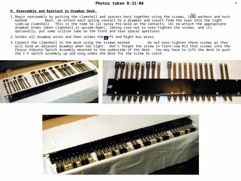
D. Reassemble and Reattach to Drawbar Desk-
1. Begin reassembly by putting the clamshell and spacers back together using the screws, lock washers and nuts marked . Next, re-attach each spring contact to a drawbar and insert from the rear into the right side-up clamshell. This is the time to (a) spray Pro Gold on the contacts, (b) re-attach the appropriate drawbar knobs (when clamshell is upside-down), taking care not to over-tighten the screws, and (C) optionally, put some silicon lube on the front and rear spacer apertures.
2. Solder all drawbar wires and then solder the Left and Right bus wires.
3. Connect the clamshell to the desk using the screws marked . Do not over-tighten these screws as they will bind an adjacent drawbar when too tight. Don’t forget the screw in Front-row #13 that screws into the Chorus Vibrato Switch Assembly mounted to the underside of the desk. You may have to lift the desk to push the C-V switch assembly up and snug under the desk for the screw to catch.
2
n
Detailed Procedure For Servicing the Drawbar Assembly
n
n
n
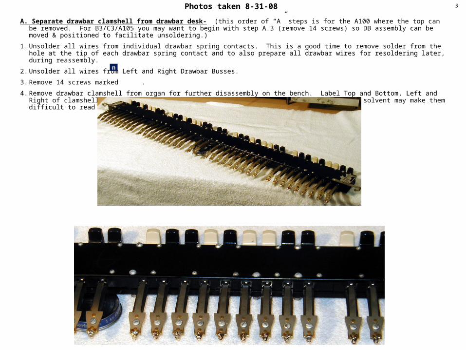
Photos taken 8-31-08 3
A. Separate drawbar clamshell from drawbar desk- (this order of “A” steps is for the A100 where the top can be removed. For B3/C3/A105 you may want to begin with step A.3 (remove 14 screws) so DB assembly can be moved & positioned to facilitate unsoldering.)
1. Unsolder all wires from individual drawbar spring contacts. This is a good time to remove solder from the hole at the tip of each drawbar spring contact and to also prepare all drawbar wires for resoldering later, during reassembly.
2. Unsolder all wires from Left and Right Drawbar Busses.
3. Remove 14 screws marked .
4. Remove drawbar clamshell from organ for further disassembly on the bench. Label Top and Bottom, Left and Right of clamshell with masking tape labels or similar, keeping in mind that cleaning solvent may make them difficult to read later on.
n
Photos taken 8-31-08 4
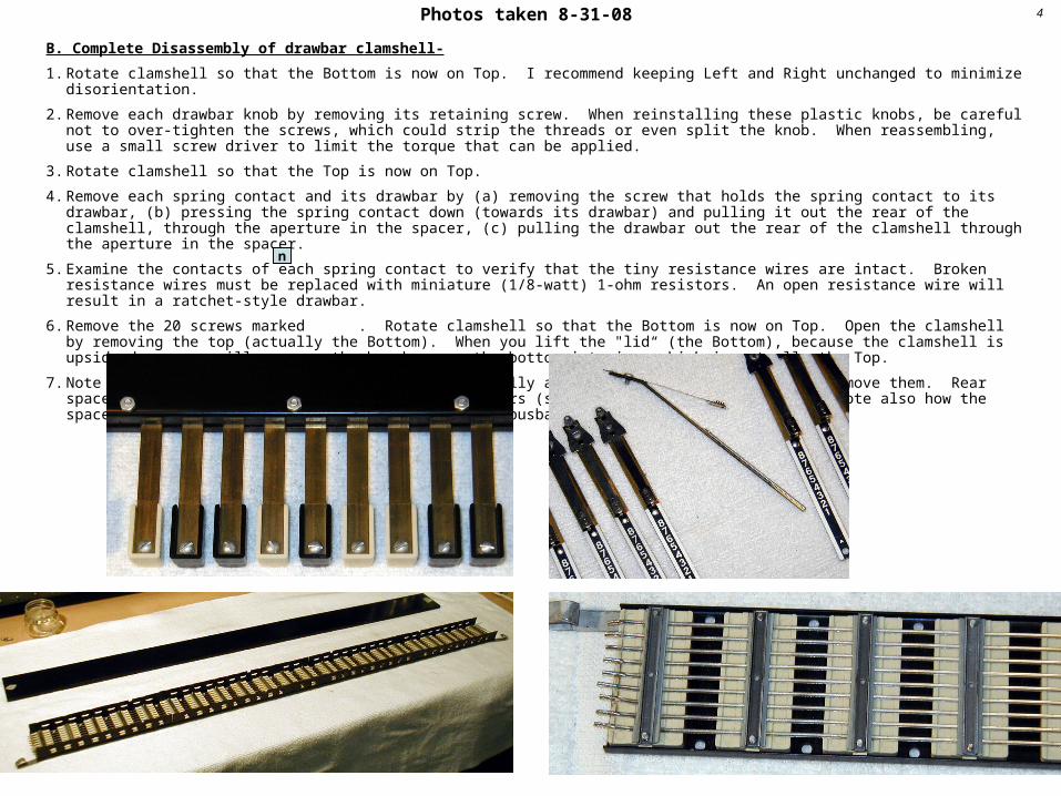
B. Complete Disassembly of drawbar clamshell-
1. Rotate clamshell so that the Bottom is now on Top. I recommend keeping Left and Right unchanged to minimize disorientation.
2. Remove each drawbar knob by removing its retaining screw. When reinstalling these plastic knobs, be careful not to over-tighten the screws, which could strip the threads or even split the knob. When reassembling, use a small screw driver to limit the torque that can be applied.
3. Rotate clamshell so that the Top is now on Top.
4. Remove each spring contact and its drawbar by (a) removing the screw that holds the spring contact to its drawbar, (b) pressing the spring contact down (towards its drawbar) and pulling it out the rear of the clamshell, through the aperture in the spacer, (c) pulling the drawbar out the rear of the clamshell through the aperture in the spacer.
5. Examine the contacts of each spring contact to verify that the tiny resistance wires are intact. Broken resistance wires must be replaced with miniature (1/8-watt) 1-ohm resistors. An open resistance wire will result in a ratchet-style drawbar.
6. Remove the 20 screws marked . Rotate clamshell so that the Bottom is now on Top. Open the clamshell by removing the top (actually the Bottom). When you lift the "lid“ (the Bottom), because the clamshell is upside down, you will now see the bus bars on the bottom interior, which is actually the Top.
7. Note the five front and rear spacers. Look carefully at their orientation before you remove them. Rear spacers have much larger openings than front spacers (see diagrams on previous page). Note also how the spacers fit over the plastic blocks that hold the busbars.
n

Photos taken 8-31-08 5
C. Clean Drawbar Assembly Components-
1. Using gasoline (petrol) and a soft-bristle toothbrush, scrub the busbars and plastic retaining blocks . Old grease doesn't like to come off, so scrub some more. You can wash the sterling busses until they're spotless. Clean all spring contacts with gas and brush, too, taking care NOT to break the tiny resistance wires. You may also want to clean the spacers, drawbars, and knobs with Fantastik or similar household cleaner. Let all components air dry or use compressed air to hasten the process.
Photos taken 8-31-08 6
D. Reassemble and Reattach to Drawbar Desk-
1. Begin reassembly by putting the clamshell and spacers back together using the screws, lock washers and nuts marked . Next, re-attach each spring contact to a drawbar and insert from the rear into the right side-up clamshell. This is the time to (a) spray Pro Gold on the contacts, (b) re-attach the appropriate drawbar knobs (when clamshell is upside-down), taking care not to over-tighten the screws, and (C) optionally, put some silicon lube on the front and rear spacer apertures.
2. Solder all drawbar wires and then solder the Left and Right bus wires.
3. Connect the clamshell to the desk using the screws marked . Do not over-tighten these screws as they will bind an adjacent drawbar when too tight. Don’t forget the screw in Front-row #13 that screws into the Chorus Vibrato Switch Assembly mounted to the underside of the desk. You may have to lift the desk to push the C-V switch assembly up and snug under the desk for the screw to catch.
n
n
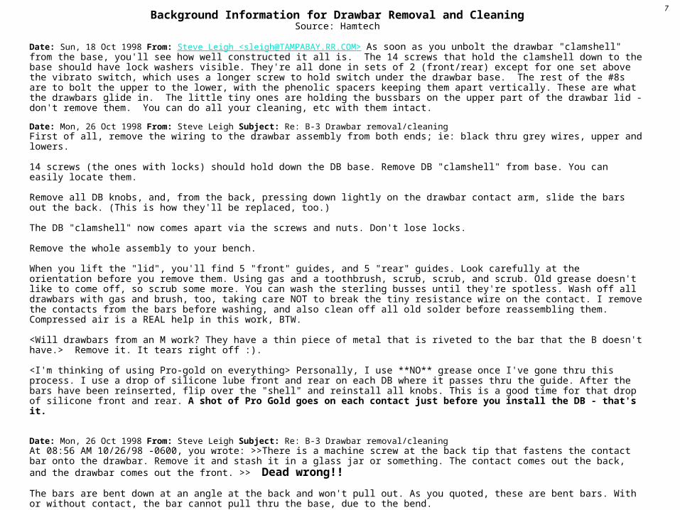
Background Information for Drawbar Removal and CleaningSource: Hamtech
Date: Sun, 18 Oct 1998 From: Steve Leigh <[email protected]> As soon as you unbolt the drawbar "clamshell" from the base, you'll see how well constructed it all is. The 14 screws that hold the clamshell down to the base should have lock washers visible. They're all done in sets of 2 (front/rear) except for one set above the vibrato switch, which uses a longer screw to hold switch under the drawbar base. The rest of the #8s are to bolt the upper to the lower, with the phenolic spacers keeping them apart vertically. These are what the drawbars glide in. The little tiny ones are holding the bussbars on the upper part of the drawbar lid - don't remove them. You can do all your cleaning, etc with them intact.
Date: Mon, 26 Oct 1998 From: Steve Leigh Subject: Re: B-3 Drawbar removal/cleaning First of all, remove the wiring to the drawbar assembly from both ends; ie: black thru grey wires, upper and lowers.
14 screws (the ones with locks) should hold down the DB base. Remove DB "clamshell" from base. You can easily locate them.
Remove all DB knobs, and, from the back, pressing down lightly on the drawbar contact arm, slide the bars out the back. (This is how they'll be replaced, too.)
The DB "clamshell" now comes apart via the screws and nuts. Don't lose locks.
Remove the whole assembly to your bench.
When you lift the "lid", you'll find 5 "front" guides, and 5 "rear" guides. Look carefully at the orientation before you remove them. Using gas and a toothbrush, scrub, scrub, and scrub. Old grease doesn't like to come off, so scrub some more. You can wash the sterling busses until they're spotless. Wash off all drawbars with gas and brush, too, taking care NOT to break the tiny resistance wire on the contact. I remove the contacts from the bars before washing, and also clean off all old solder before reassembling them. Compressed air is a REAL help in this work, BTW.
<Will drawbars from an M work? They have a thin piece of metal that is riveted to the bar that the B doesn't have.> Remove it. It tears right off :).
<I'm thinking of using Pro-gold on everything> Personally, I use **NO** grease once I've gone thru this process. I use a drop of silicone lube front and rear on each DB where it passes thru the guide. After the bars have been reinserted, flip over the "shell" and reinstall all knobs. This is a good time for that drop of silicone front and rear. A shot of Pro Gold goes on each contact just before you install the DB - that's it.
Date: Mon, 26 Oct 1998 From: Steve Leigh Subject: Re: B-3 Drawbar removal/cleaningAt 08:56 AM 10/26/98 -0600, you wrote: >>There is a machine screw at the back tip that fastens the contact bar onto the drawbar. Remove it and stash it in a glass jar or something. The contact comes out the back, and the drawbar comes out the front. >> Dead wrong!!
The bars are bent down at an angle at the back and won't pull out. As you quoted, these are bent bars. With or without contact, the bar cannot pull thru the base, due to the bend.
The only way to remove, is to remove DB knob first, and slide the assembly out the rear. Removing the contact is not necessary.
Date: Sat, 30 Mar 2002 From: john freund <[email protected]> Subject: Drawbar cleaning When taking your drawbar assembly apart for cleaning, not only should you take copious notes about which screws go where and do what, but also mark the assembly so that when you put it back together the lower manual and pedals are on the same busses
7

Background Information for Drawbar Removal and CleaningSource: Hamtech
Date: Thu, 9 Jul 1998 From: Steve Blair <[email protected]> Subject: Re: Drawbarspaul l perron wrote: > I > have problem with static in the drawbars. The sound cuts in & out and they have to be jiggled sometimes. Any advice?
Paul- Here's a previous post on the subject. This assumes you have the more modern "non-rachet" drawbars. I'm surprised more Hammond owners on the list have not brought up this problem. The symptoms are very subtle, but there should be absolutely *no* "tonus interuptus" as a drawbar is slowly pulled out. Good Luck. Steve Blair ------------------------
" Be sure the nichrome resistance wire (1 ohm) is not broken. If it (they) are, do not try to solder them. Go forth and buy 1/8 watt 1 ohm resistors and solder them where the wire was. They fit just duckey and work great." (Wise words from Bob S. in the Hammond FAQ.)
If the tone goes on and off as you slowly pull a drawbar out, then the nichrome wire on that drawbar is broken. Last night I repaired 10 of the 38 drawbars on my A100 using the above info. I was surprised that more than 25% of the little wires were broken in the first place. After all, they are so well protected inside the drawbar assembly.
The repair is very simple, especially on an A100. With the top of the organ off, and working from the backside, simply remove the tiny screw at the end of the drawbar, just above where the large preset wire is soldered on. This separates the upper arched strip of the drawbar from the main sliding arm. On the top end of the strip are the 2 metal tips that contact the busbars. On the underside, the 2 metal tips should be connected with the nichrome wire (it's more like a metal hair). I could barely see the wire and had to use a toothpick to verify that it was indeed broken. One wire was still intact but there was no electrical continuity across the tips. In 2 cases, it appeared that a wire was never installed (no wire or solder marks).
The tiny 1 ohm resistor was easy to tie off, solder into place, then trim the excess leads. All my drawbars work "continuously" now with no more interruptus. So check all your drawbars, and don't be afraid to try this repair. Resistors are about $0.10 each. Just be careful not to drop any screws down into the tone generator. Steve in Berkeley
And a tip for replacement: The original resistors are welded to the DB body and contact. If you clip out the original resistor body leaving most of the leads, this leaves nice tin-plated pieces of wire to solder the new one to; also it allows you to use a heat sink clip to avoid melting any plastic. Eric Tucker
8
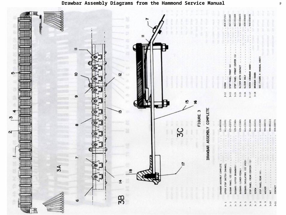
9Drawbar Assembly Diagrams from the Hammond Service Manual

10A different kind of draw at the bar
Edouard ManetLe Bar aux Folies-Bergère
1881-82; Courtauld Institute Galleries, London This sparkling portrayal shows extensive use of peinture claire, a technique Manet himself evolved.
(b. Jan. 23, 1832, Paris, France--d. April 30, 1883, Paris) French painter and printmaker who in his own work accomplished the transition from the realism of Gustave Courbet to Impressionism. Manet broke new ground in choosing subjects from the events and appearances of his own time and in stressing the definition of painting as the arrangement of paint areas on a canvas over and above its function as representation. Exhibited in 1863 at the Salon des Refusés, his Le Déjeuner sur l'herbe ("Luncheon on the Grass") aroused the hostility of the critics and the enthusiasm of a group of young painters who later formed the nucleus of the Impressionists. His other notable works include Olympia (1863) and A Bar at the Folies-Bergère (1882).