halomethyllithium carbenoid cyclopropanation reactions: a...
TRANSCRIPT
Cyclopropanation Reactions of Halomethyllithium Carbenoids:
A Computational Study of the Effects of Aggregation and Solvation
Lawrence M. Pratt*1
Phương Thảo Thị Trần
Department of Chemistry
Fisk University 1000 17th Ave. N.
Nashville, TN 37209 [email protected]
2
B. Ramachandran*
and Ngân Văn Nguỹên
University of Pedagogy 280 An Duong Vuong
District 5, Ho Chi Minh City, Vietnam
3
1 E-mail: [email protected] 2 Current address: Gia Dinh High School,195/29, Xo Viet Nghe Tinh Street, Binh Thanh District, Ho Chi Minh
City, Vietnam. 3 E-mail: [email protected]
Chemistry, College of Engineering & Science
Louisiana Tech University Ruston, LA 71272
BCSJ Manuscript No.:O-08227 Submitted: September 10, 2008 Accepted: May 25, 2009
Running title: Cyclopropanation Reactions of Halomethyllithium Carbenoids
1
ABSTRACT
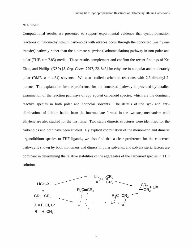
Computational results are presented to support experimental evidence that cyclopropanation
reactions of halomethyllithium carbenoids with alkenes occur through the concerted (methylene
transfer) pathway rather than the alternate stepwise (carbometalation) pathway in non-polar and
polar (THF, ε = 7.85) media. These results complement and confirm the recent findings of Ke,
Zhao, and Phillips (KZP) [J. Org. Chem. 2007, 72, 848] for ethylene in nonpolar and moderately
polar (DME, ε = 4.34) solvents. We also studied carbenoid reactions with 2,3-dimethyl-2-
butene. The explanation for the preference for the concerted pathway is provided by detailed
examination of the reaction pathways of aggregated carbenoid species, which are the dominant
reactive species in both polar and nonpolar solvents. The details of the syn- and anti-
eliminations of lithium halide from the intermediate formed in the two-step mechanism with
ethylene are also studied for the first time. Two stable dimeric structures were identified for the
carbenoids and both have been studied. By explicit coordination of the monomeric and dimeric
organolithium species to THF ligands, we also find that a clear preference for the concerted
pathway is shown by both monomers and dimers in polar solvents, and solvent steric factors are
dominant in determining the relative stabilities of the aggregates of the carbenoid species in THF
solution.
CR2CR2X
Li
LiX
R2C CR2
LiCH2X
+CR2 CR2
CR2CR2
+ LiX
R2C CR2
Li XX = F, Cl, Br
R = H, CH3
Running title: Cyclopropanation Reactions of Halomethyllithium Carbenoids
2
1. Introduction This paper presents a detailed computational study of the reactions leading to the
formation of cyclopropane rings by the insertion of a methylene group into a carbon-carbon
double bond by halomethyllithium carbenoids Li-CH2-X, where X = F, Cl, and Br. This work
complements, and indeed confirms, many of the results recently reported by Ke, Zhao, and
Phillips (KZP),1
The widespread use of organometallic carbenoid species for synthesizing cyclopropane
rings has a long history dating back at least to the 1958 report by Simmons and Smith [using the
“Simmons-Smith” (SS) reagent IZnCH2I]
but we also report several novel findings.
2 which was followed up by a more detailed report in
1959.3 On the basis of the stereospecificity of the reaction and other experimental observations,
Simmons and Smith proposed a direct, or concerted, addition of CH2 to the double bond as the
mechanism. A two-step mechanism involving carbometalation of the alkene, resulting in X-
(CH2)3-M (where X is the halogen and M the metal) as intermediate, was proposed by Hoberg in
1962.4 Although Burger and Huisgen in 19705 ruled out this mechanism for X = Cl and M = Li
on the basis of the stereospecificity of the reaction, the collection of available experimental
evidence is not conclusive. For example, Stiasny and Hoffmann6 studied intramolecular
cyclopropanation reactions using bromolithium carbenoids and observed that the direct
mechanism appears to have the lowest activation energy, proceeding quite readily even at
extremely low temperatures (–110 °C). However, they also concluded that Lewis-acid assisted
carbolithiation leading to cyclopropanation (the two-step mechanism) was competitive at higher
temperatures (–20 °C or higher). The possibility of free carbenes (rather than lithiocarbenoids)
being responsible for the reaction has been ruled out by the complete absence of hydrocarbon
isomerization products in these experiments.
Running title: Cyclopropanation Reactions of Halomethyllithium Carbenoids
3
One of the first computational studies of the reactions considered here appear to be that
of Nakamura et al.7 who briefly examined the case of Li-CH2-Cl for comparison while
conducting a study of the SS reactions. Based on the Born-Oppenheimer (or classical) energy
barrier heights of gas phase (or nonpolar solvent) reactions involving monomeric carbenoid
species at the B3LYP/6-31G(d) level, Nakamura et al. concluded that no preference exists
between the two pathways for the case of Li (in contrast, the SS reaction showed a clear
preference for the concerted mechanism). Hermann et al. studied the concerted pathway only, in
a study of the influence of leaving groups (X = F, Cl, Br, I, and OH).8 The most recent and most
detailed study to date, and the only one to consider the influence of aggregates and explicit
solvation, is that of KZP1 in which X = F and OH are studied at the B3LYP/6-311G(d,p) level of
theory. That paper is part of a long series of outstanding computational investigations of
metalocarbenoid-mediated cyclopropanation reactions from Phillips and coworkers.9,10,11,12,13 In
this paper, we present a detailed study of the reactions of halomethyllithium species with
ethylene and examine the relative viability of the two reaction pathways for X = F, Cl, and Br, at
HF, B3LYP, and MP2 levels of theory using the 6-31+G(d) basis set. Many aspects of our work
complement and confirm the results of KZP but several aspects are also novel and are
summarized towards the end of this Section. It is important to note that although the fluoro
substituent is easier to handle computationally compared to the chloro and bromo substituents,
the chemistry of fluoro compounds can be quite different. An investigation of the Fritsch-
Buttenberg-Wiechell (FBW) rearrangement of lithium vinylidine carbenoids is currently in
progress in Pratt’s laboratory. Preliminary results show that the fluoro substituent affects not
only the barrier height, but in some cases, even the mechanism of rearrangement.14 This can be
attributed to not only the greater electronegativity of fluorine, but the acid-base properties as
Running title: Cyclopropanation Reactions of Halomethyllithium Carbenoids
4
well. Fluoride ion is a hard base, while chloride and bromide ions are comparatively soft bases,
and bind less strongly with the hard lithium cation and proton. Thus, fluoromethyllithium
reactions may parallel those of the more synthetically useful chloro- and bromomethyllithium
carbenoids in some cases, but we cannot generally expect to find similar barrier heights or even
the same mechanism.
Lithium carbenoids are important reagents in synthetic organic chemistry. In addition to
halomethyllithiums, carbene-like reactivity has been observed in 1-halo-1-lithioalkenes and α-
lithioethers, particularly oxiranyllithium compounds. As carbene-like species, lithium
carbenoids undergo a variety of single and double bond insertion reactions. Nucleophilic
reactions of related oxiranyllithium carbenoids are also known.15,16,17,18 The chemistry of
organolithium compounds in general is quite complex because of their tendency to form
aggregates in solution. The reactivity and the thermochemistry often depend sensitively on the
aggregation state and solvation effects.19,20 The precise nature of the reactive species is difficult
to characterize experimentally and, therefore, computational investigations are necessary to
further our understanding. However, computational investigations of organolithium chemistry
also present many challenges. Semi-empirical methods are poorly parameterized for lithium
compounds.21 Moreover, electron correlation effects appear to be quite important in the
intermolecular interactions in these species, which means that relatively high levels of theory are
necessary. Ethereal solvents like THF bind quite strongly as ligands to the lithium atoms,
forming a “supermolecule” consisting of the organolithium molecule and its first solvation
sphere.22,23 Steric and electronic effects of the coordinated ligands are important and the steric
effects, in particular, cannot be adequately represented by continuum solvation models.
Running title: Cyclopropanation Reactions of Halomethyllithium Carbenoids
5
The present work studies the cyclopropanation reactions of (Li-CH2-X)n (n = 1,2,4)
where X = F, Cl, or Br, with ethylene and (Li-CH2-X)2 with 2,3-dimethyl-2-butene (DMB),
using Hartree-Fock, hybrid density functional theory (B3LYP), and second order Møller-Plesset
perturbation theory (MP2), all using the 6-31+G(d) basis set. Reactions of the monomers and
dimers with ethylene are modeled both in the gas phase and in THF solution. Gas phase
reactions provide a standard against which to gauge the influence of solvation on reaction
energetics, but the results should also be reasonable approximations to non-coordinating solvent
environments which were employed in the experiments of Burger and Huisgen5 and those of
Stiasni and Hoffmann.6 We consider single-step insertion of the methylene group into the
ethylene double bond as well as the stepwise pathways in which a 3-halo-1-propyllithium is first
formed which then undergoes a syn or anti elimination of the lithium halide to yield the
cyclopropane ring. Analogous reactions of the dimeric species are also studied in detail along
with a brief examination of the direct insertion mechanism of the tetramer. The reactions of (Li-
CH2-X)2 with dimethylbutene are studied in the gas phase so as to confirm that the trends
emerging from the detailed studies on ethylene are also observed for other alkene species.
Given the uncertainties as to the reaction mechanisms, Intrinsic Reaction Coordinate
(IRC) calculations24,25 have been performed to verify whether the transition states identified are,
in fact, the ones that connect the reactants to the intermediates or products. Finally, these
reactions are also modeled in THF solution, represented by THF molecules coordinated to the
lithium atoms. In addition to full optimization of all reactants, products, and transition state (TS)
structures at the HF, B3LYP, and MP2 levels of theory, we also compare energies (minima as
well as saddle-points) from single point MP2 calculations at B3LYP-optimized geometries
(MP2//B3LYP) to evaluate the reliability of the hybrid DFT approach to the study of these
Running title: Cyclopropanation Reactions of Halomethyllithium Carbenoids
6
reactions. A few stationary points along the gas phase reaction paths have also been examined at
the CCSD(T)/6-31+G(d) level of theory.
Some of novel findings reported in the current work are the following:
1. First detailed study of cyclopropanation reactions of (Li-CH2-X)n, (n > 1) for X = Cl and
Br, which are more widely used for synthetic work than the X = F case studied by KZP.
2. The first detailed study of the reactions of (Li-CH2-X)2 with dimethylbutene.
3. First study of the details of the second step of the two-step process proposed by Hoberg.4
We find that, contrary to earlier assumptions, the reaction barriers for the eliminiation of
LiX from the intermediate 1-halo-3-propyllithiums are comparable to those of the first
step.
4. The MP2/6-31+G(d) level IRC calculations reveal that a pre-reactive complex is formed
only in the case of the stepwise (carbometalation) mechanism for monomers and dimers.
5. Study of the reactions in THF solvent reveal interesting differences in the properties of
the molecules from the dimethyl ether (DME) environment studied by KZP.
6. Comparison of MP2 and MP2//B3LYP (i.e., MP2 single point calculation at B3LYP
geometry) energies for the relevant species involved in the various pathways reveal that
B3LYP geometries are quite close to the MP2 ones in the gas phase, but there are
important differences between the THF-solvated structures predicted by the two methods.
7. In addition to the dimeric species studied by KZP (labeled 6 below), the reactions of a
constitutional isomer (labeled 7 below) are also examined, and the latter is found to
provide a lower energy pathway to products.
Running title: Cyclopropanation Reactions of Halomethyllithium Carbenoids
7
8. The stability of solvated tetramers relative to the solvated dimers is examined. We
conclude that dimers are the predominant aggregated species of LiCH2X in THF solvent.
9. Comparison of continuum solvation (PCM) results and explicit solvation for the
tetramers reveal that the relative instability of solvated tetramers (see item 8 above) is
primarily due to steric effects in the primary solvation sphere, not electrostatic effects in a
polar solvent.
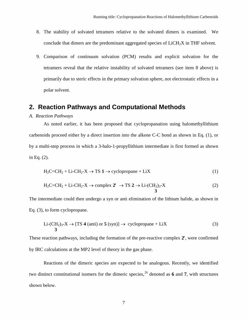
2. Reaction Pathways and Computational Methods A. Reaction Pathways As noted earlier, it has been proposed that cyclopropanation using halomethyllithium
carbenoids proceed either by a direct insertion into the alkene C-C bond as shown in Eq. (1), or
by a multi-step process in which a 3-halo-1-propyllithium intermediate is first formed as shown
in Eq. (2).
H2C=CH2 + Li-CH2-X → TS 1 → cyclopropane + LiX (1)
H2C=CH2 + Li-CH2-X → complex 2′ → TS 2 → Li-(CH2)3-X (2) 3 The intermediate could then undergo a syn or anti elimination of the lithium halide, as shown in
Eq. (3), to form cyclopropane.
Li-(CH2)3-X → [TS 4 (anti) or 5 (syn)] → cyclopropane + LiX (3) 3
These reaction pathways, including the formation of the pre-reactive complex 2′, were confirmed
by IRC calculations at the MP2 level of theory in the gas phase.
Reactions of the dimeric species are expected to be analogous. Recently, we identified
two distinct constitutional isomers for the dimeric species,26 denoted as 6 and 7, with structures
shown below.
Running title: Cyclopropanation Reactions of Halomethyllithium Carbenoids
8
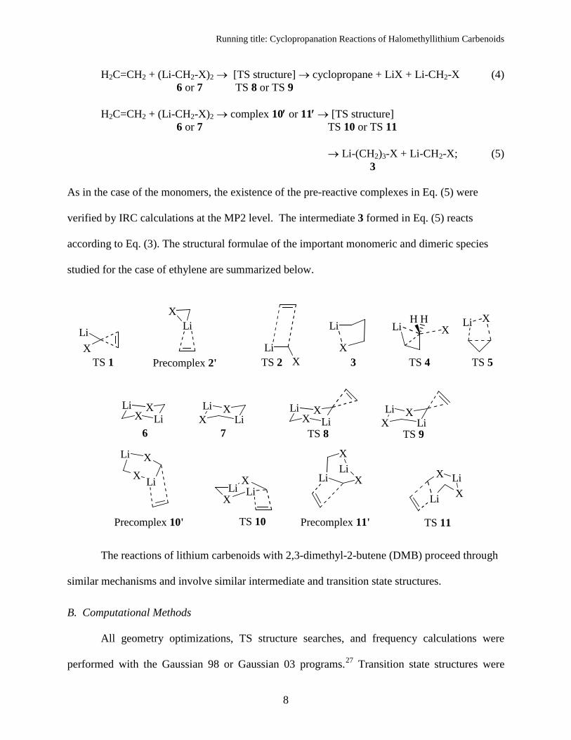
H2C=CH2 + (Li-CH2-X)2 → [TS structure] → cyclopropane + LiX + Li-CH2-X (4) 6 or 7 TS 8 or TS 9 H2C=CH2 + (Li-CH2-X)2 → complex 10′ or 11′ → [TS structure] 6 or 7 TS 10 or TS 11 → Li-(CH2)3-X + Li-CH2-X; (5) 3 As in the case of the monomers, the existence of the pre-reactive complexes in Eq. (5) were
verified by IRC calculations at the MP2 level. The intermediate 3 formed in Eq. (5) reacts
according to Eq. (3). The structural formulae of the important monomeric and dimeric species
studied for the case of ethylene are summarized below.
XLi
TS 1Li
XTS 2X
Li
3
Li XH H
TS 4
Li X
TS 5
LiX Li
X LiX Li
X
6 7
LiX Li
X LiX Li
X
TS 9TS 8
XLi
XLi
TS 10
X LiXLi
TS 11
LiX
Precomplex 2'
Precomplex 10' Precomplex 11'
Li
XX
Li
XLi
XLi
The reactions of lithium carbenoids with 2,3-dimethyl-2-butene (DMB) proceed through
similar mechanisms and involve similar intermediate and transition state structures.
B. Computational Methods
All geometry optimizations, TS structure searches, and frequency calculations were
performed with the Gaussian 98 or Gaussian 03 programs.27 Transition state structures were
Running title: Cyclopropanation Reactions of Halomethyllithium Carbenoids
9
located with either the QST3 method, or by further optimization of a previously located
transition structure at a different level of theory using the Opt=TS keyword. Geometry
optimizations were performed at the HF/6-31+G(d), B3LYP/6-31+G(d), and MP2/6-31+G(d)
levels of theory for both the reactants and transition structures. MP2 single point energy
calculations were performed at the B3LYP geometries to determine whether B3LYP generates
satisfactory geometries at a fraction of the computational cost of full MP2 optimizations.
Harmonic frequencies of the reactants and transition structures were calculated at the HF/6-
31+G(d) level. Since cyclopropanation reactions are typically carried out at very low
temperatures, free energy corrections were calculated at 173.15 K from these frequency
calculations and added to the electronic energies at each level of theory, in order to obtain
approximate free energies of each reactant and TS structure.
Intrinsic reaction coordinate (IRC) calculations were performed using the algorithms of
Gonzalez and Schlegel28
Solvent effects were modeled by placing explicit THF ligands on the lithium atoms. Two
ligands were used for each carbenoid monomer, and either three or four ligands for the dimers.
Special care is taken to ensure consistent handling of standard states.
as implemented in Gaussian 03. The reaction coordinate is expressed
as a mass-weighted distance along the path of steepest descent from its origin at the saddle point
towards the reactants (negative values) and towards products (positive values).
29,30 Specifically, a
correction term RTln(c°RT/P°) must be added per mole of each species in the reaction under
consideration, which represents the change in free energy involved in compressing the system
from standard pressure P° (or a concentration of P°/RT) used in gas phase calculations to the
standard concentration of c° = 1 mol/L commonly used for solutions. This term is numerically
equal to +0.9131 kcal/mol at 173.15 K and, while it cancels from both sides when the net change
Running title: Cyclopropanation Reactions of Halomethyllithium Carbenoids
10
in the number of moles due to reaction ∆n = 0, it is a non-negligible correction in cases where ∆n
≠ 0. Yet another correction is required for cases where a THF ligand dissociates, as in
RLi·nTHF → ← RLi·mTHF + (n – m)THF
for which
∆G° = –RTln[RLi·mTHF][RLi·nTHF] – (n –m) RTln
[THF]c° . (6)
Since the concentration of pure THF is different from the standard concentration c°, it was
evaluated from its molar volume at 1 atm and 173.15 K using the empirical expression provided
by Govender et al.31 and incorporated into the second term of Eq. (6). Numerically, this
correction to ∆G° amounts to –0.9014 kcal per mole of free THF at 173.15 K. This approach to
modeling solvation effects on organolithium compounds has been used in other
studies,30,32,33,34,35,36,37
3. Results and Discussion
and has been found to give results in agreement with available
experimental results.
A. Reactions of gas phase monomers with ethylene
The MP2/6-31+G(d) level IRC’s for the reactions of the gas phase monomers given in
Eqs. (1) and (2) are presented in Figure 1, for the case of X = Br. The solid symbols connected
by the solid line represents the IRC of the concerted mechanism (Eq. 1). The point A represents
the farthest point along the IRC for which structures could be converged, starting from the
transition state TS 1 and proceeding towards the reactants. The empty symbols connected by the
solid line represents the IRC for the first step of the stepwise mechanism (Eq. 2), and the point D
represents the minimum value of the IRC for which structures could be converged, starting from
the transition state TS 2 and proceeding towards the reactants. The nature of this IRC suggested
Running title: Cyclopropanation Reactions of Halomethyllithium Carbenoids
11
that a pre-reactive complex 2′ is being formed. The optimized structure of this complex is
represented by the point C, which is placed schematically on the IRC (i.e., the value of the
reaction coordinate for this point is guided only by the physically reasonable expectation that the
IRC should smoothly connect the point D to the reactants while passing through C). Spline
interpolations connecting these calculated points to the asymptotic reactants in a physically
reasonable manner are shown as dashed lines. The molecular structures corresponding to the
labeled points are shown in Figure 2. We have examined and confirmed that the IRC’s and
structures for the cases X = F and Cl are qualitatively similar.
*** Suggested location for Figs. 1 and 2 ***
We first consider the concerted mechanism via TS 1. It is clear from the IRC shown in
Figure 1 and the structures shown on the top row of Figure 2 that the reaction is initiated by the
interaction of the methylene group with the π-bond of the alkene, leading to the direct insertion
of the CH2 group into the ethylene double bond, resulting in the formation of the cyclopropane
ring. The essential stages of the stepwise mechanism are quite different. This pathway starts by
the interaction of the lithium with the π-bond of the alkene, leading to the formation of a pre-
reactive complex 2′. A rearrangement of this complex leads to the structure D, then to the four-
membered ring structure of TS 2 and eventually the intermediate 3.
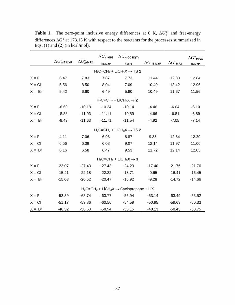
The zero-point inclusive relative (with respect to reactants) energies at 0 K, ∆U°0 , and
Gibbs free energy changes at 173.15 K and standard pressure, ∆G°, for the processes
summarized in Eqs. 1 and 2 are given in Table 1 for all three halogens and the different levels of
theory examined. We have omitted the Hartree-Fock results in the Table. Because of the
correction term mentioned in the paragraph above Eq. (6), the ∆G° for the formation of TS 1,
pre-reactive complex 2′, and TS 2 will each be lowered by 0.91 kcal/mol in non-polar solvents.
Running title: Cyclopropanation Reactions of Halomethyllithium Carbenoids
12
*** Suggested location for Table 1 ***
The zero-point-energy inclusive reaction barrier ( ‡0U∆ ) of KZP1 [B3LYP/6-311G(d,p)]
to form TS 1 (X = F) is 7.8 kcal/mol, compared to our own B3LYP/6-31+G(d) result of
6.47 kcal/mol. For TS 2, KZP report a ‡0U∆ of 4.3 kcal/mol, which compares well with the
4.11 kcal/mol reported in Table 1. The ∆U°0 for the pre-reactive complex C is –8.2 kcal/mol in
Ref. 1, and –8.60 kcal/mol in our work. The ∆U°0 for the formation of cyclopropane and the
intermediate 3 are –60.3 kcal/mol and –23.2 kcal/mol, respectively in Ref. 1, compared to –53.39
and –23.07 kcal/mol, respectively, in our work. We conclude that the methods and basis sets
used in this paper are of sufficiently high quality to yield qualitatively correct results while
remaining small enough for MP2 level calculations on the aggregates of the X = Cl and Br cases.
Table 1 also shows that the MP2//B3LYP energies are within ±1 kcal/mol to the MP2 results,
indicating that B3LYP geometries are consistently of MP2 quality in this case. We will see
below that there are some instances where this is not the case.
The IRC’s in Figure 1 and the results tabulated in Table 1 show that the ‡0U∆ for the
formation of TS 1 and TS 2 are comparable for all three halogens. As mentioned in the
Introduction, this is contrary to experimental evidence which indicates a clear preference for the
concerted pathway. Examination of aggregated structures, first reported by KZP in Ref. 1 and
which we will present shortly, yields results that support existing experimental evidence.
In contrast to KZP’s Figure 1, we were not able to identify a pre- reactive complex on the
IRC for the concerted mechanism, using B3LYP or MP2. As indicated by Figure 1, the IRC for
the concerted reaction rapidly approaches its asymptotic value and shows no indication of
dipping below that value. We could not force the IRC calculation beyond the point labeled A in
Running title: Cyclopropanation Reactions of Halomethyllithium Carbenoids
13
Figure 1, presumably because the energy landscape becomes very flat quite rapidly. In sharp
contrast, the IRC for the carbometalation mechanism could be extended beyond the point D
towards C with no difficulty.
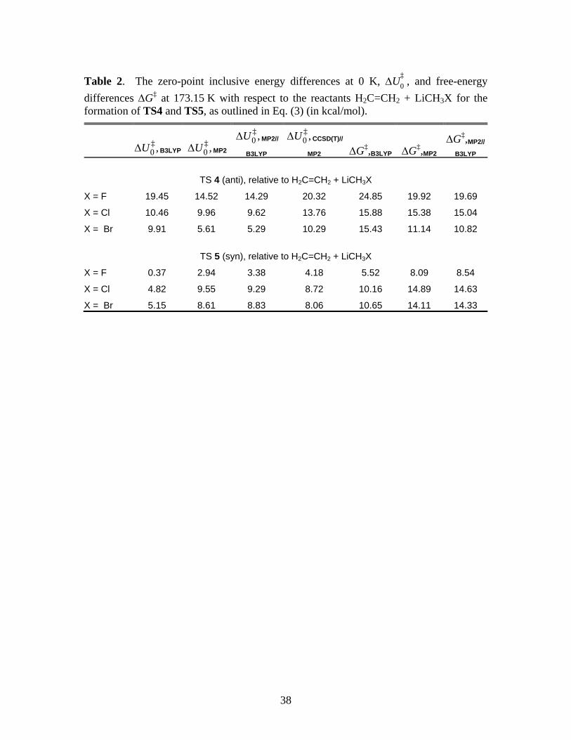
To the best of our knowledge, there has been no study of the details of the second step of
the two-step mechanism in which the LiX is eliminated, leaving behind the cyclopropane ring.
As shown in Eq. (3), the second step could occur in either an anti geometry, similar to an SN2
reaction (TS 4), or in a syn fashion (TS 5), with the lithium and halide ions eliminating from the
same side of the intermediate. As a representative of the methods and molecules studied, we
show the B3LYP/6-31+G(d) IRC’s in Figure 3 for LiCH2Cl. The relevant structures are
presented in Figure 4. For anti elimination (TS 4), we encountered convergence difficulties
beyond either extremes of the IRC shown. Comparing the structures in panels F, TS2, and G of
Figure 4, it appears that anti-elimination results in a cyclopropane ring that continues to interact
with the lithium cation as the chloride ion is leaving. The ‡0U∆ and ∆G‡ for the anti and syn
eliminations are summarized in Table 2.
*** Suggested location for Figs. 3 and 4 ***
*** Suggested location for Table 2 ***
There are significant differences between the ∆G‡ for the different halogen species for the
second step of the two-step mechanism. Focusing on MP2 and MP2//B3LYP energies, there
appears to be a clear preference for syn elimination in the case of X = F, a preference for the anti
elimination in the case of X = Br, and no clear preference in the case of X = Cl. These results
can be rationalized on the basis of Lewis acid-base interactions. The hard fluoride ion binds
strongly to the hard lithium ion in the transition state, thus favoring syn elimination. In contrast,
Running title: Cyclopropanation Reactions of Halomethyllithium Carbenoids
14
the bromo carbenoid favors a backside, SN2-like elimination mechanism. Once again, all free
energy values will decrease by 0.91 kcal/mol in non-polar solvent environment.
B. Reactions of gas phase dimers with ethylene
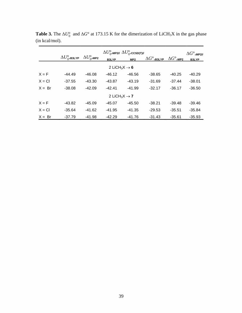
Our previous work suggested that halomethyllithium carbenoids are gas phase dimers,
and may be largely dimeric in ethereal solvents.38
*** Suggested location for Table 3 ***
As noted earlier, we have identified two
distinct constitutional isomers for the dimeric species.26 The dimerization free energies are
found to be substantial, as shown in Table 3. Since both dimeric species are of comparable
stability, we consider the reactions of both species.
The MP2/6-31+G(d) IRC’s for the concerted and stepwise reactions of 6 (X = Br) are
shown in Figure 5(a), and the analogous IRC’s for 7 (X = Br) are shown in Figure 5(b). The
structures corresponding to the labeled points in Figure 5(a) are presented in Figure 6, and those
for Figure 5(b) are in Figure 7. The pre-reactive complex leading to TS 10 is designated as 10′
and that leading to TS 11 as 11′, both denoted by the points C on the IRC’s in the panels of Fig.
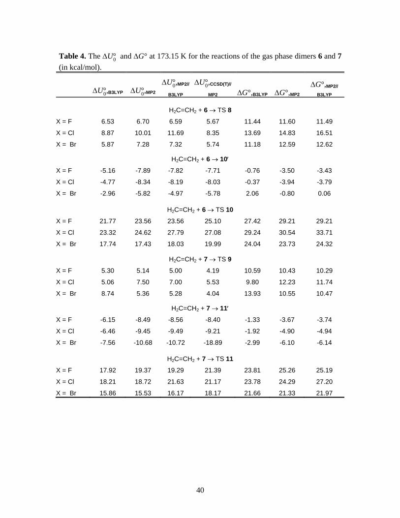
5. Table 4 summarizes the ∆U°0 and ∆G° data.
*** Suggested location for Figs. 5, 6, and 7 ***
*** Suggested location for Table 4 ***
The two panels of Figure 5 immediately reveal that the reaction barrier for the stepwise
mechanism is substantially higher than that for the direct insertion pathway for both dimeric
species. The ∆U°0 and ∆G° data in Table 4 reveal that this is true for all three halomethyllithium
species studied. Recall that in the case of gas-phase monomers, there was no clear preference
between the direct and stepwise mechanisms on the basis of barrier heights (Figure 1 and Table
Running title: Cyclopropanation Reactions of Halomethyllithium Carbenoids
15
1). Since the dimers are markedly more stable than the monomeric species (Table 3), they are
among the dominant reactive species present. Therefore, it appears that one of the reasons
computational studies prior to those of KZP failed to establish the preference for the concerted
pathway over the carbometalation pathway for cyclopropanation reactions of halomethyllithiums
was because they did not consider dimeric species.
Tables 1-4 also contain the ∆U°0 values calculated at CCSD(T)/6-31+G(d) level of theory
at MP2 geometries. There are no qualitative differences between the MP2 and CCSD(T) results
in any case and, in many cases, the calculated energy differences are comparable. In Table 1,
CCSD(T)//MP2 energy barriers for TS2 are higher than those for TS1, indicating a slight
preference for the concerted mechanism even in the case of the monomeric LiCH2X. A notable
difference between the MP2 and CCSD(T) results are in the ∆U°0 for the formation of the pre-
reactive complex of dimer 7 [Table 4, 11′ (from 7)] for X = Br. We are unable to explain the
nearly 9 kcal/mol difference between the MP2 and CCSD(T) results in this case, especially given
that the two sets of results are comparable for the formation of 10′ (from 6) for X = Br and for
the other halogens.
The data in Table 4 show that the highest barrier height is found in the reaction of the
chloromethyllithium dimers. Comparison of the bromo- and chloromethyllithium reactions
suggests that the breaking of the weaker C-Br bond is significant in the transition state.
However, the C-F bond is even stronger than the C-Cl bond, so fluoromethyllithium would be
expected to have the highest barrier height based on bond strengths. Closer examination of the
transition state geometries shows the product to be a carbenoid-LiX mixed aggregate. The
strong hard acid-hard base interaction between lithium and fluorine apparently stabilizes the
transition state leading to that product.
Running title: Cyclopropanation Reactions of Halomethyllithium Carbenoids
16
C. Reactions of THF solvated monomers with ethylene
The primary solvation shell of lithium carbenoids in THF appears to consist of two THF
ligands strongly bound to the Li. Steric factors inhibit the coordination by additional solvent
molecules. These bis-THF solvated carbenoid monomers were found to undergo similar
reactions to those in the gas phase. The direct insertion is initiated by the interaction of the
methylene group with the alkene double bond, leading to TS 1·2THF.
Unlike the gas-phase carbometalation reactions and the calculations of KZP with
coordinated DME ligands, we were unable to identify a pre-reactive complex for the bis-THF
solvated monomers. An intermediate similar to the gas phase pre-reactive complex 2′ in Figure
1 was found for the monosolvated case:
H2C=CH2 + LiCH2Cl·1THF → 2′·1THF (X = Cl); ∆U °0,B3LYP = –2.90 kcal/mol (7)
However, relative to ethylene and LiCH2Cl·2THF, the formation of the monosolvated complex is
energetically unfavorable:
H2C=CH2 + LiCH2X·2THF → 2′·1THF (X = Cl) + THF; ∆U °0,B3LYP = 8.55 kcal/mol (8)
The formation of the pre-reactive complex is also unfavorable on the basis of free energy change,
which is found to be ∆G° = +4.13 kcal/mol for Eq. (7) and +9.90 kcal/mol for Eq. (8) at
B3LYP/6-31+G(d) level.
KZP report a weakly bound ( 0,B3LYP/6-311G( , )d pU∆ = –1.4 kcal/mol) complex between
LiCH2F·2DME and ethylene, but the alkene is more than 5 Å away from the solvated species
(Figure 4 of Ref. 1). We searched for, but could not find, a similar complex for LiCH2X·2THF
at the DFT or MP2 levels of theory. It appears that the more rigid structure of the THF ligands
and their stronger interaction with the Li atom introduces greater steric and energetic constraints
Running title: Cyclopropanation Reactions of Halomethyllithium Carbenoids
17
that are not present in the DME solvent. In spite of the absence of a stable pre-reactive complex
in the case of the bis-THF solvated monomers, the stepwise addition appears to follow the
essential stages of the gas phase reaction, including the formation of the four-membered TS
2·2THF leading to the intermediate 3·2THF.
The MP2/6-31+G(d) optimized TS structures for the concerted and stepwise insertions
(TS 1·2THF and TS 2·2THF, respectively) and the intermediate 3·2THF are shown in Supporting
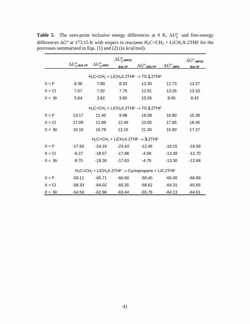
Information. The related free energy data are summarized in Table 5.
*** Suggested location for Table 5 ***
Comparison of the MP2 and MP2//B3LYP results in Tables 1 and 5 show that, with the
exception of X = Br, solvation has no significant effect on the ∆G‡ for direct insertion while
solvation increases the barrier heights for the stepwise reaction by 3 to 7 kcal/mol. (The
difference in the ∆G‡ of TS 2 and TS 2·2THF are much larger at the B3LYP level of theory,
ranging from 9 to 11 kcal/mol). Unlike the gas phase, the concerted mechanism is preferred over
the stepwise reaction of monomers when explicit THF solvation is considered. These
observations are consistent with the trends in the energy barriers reported by KZP (Table 1 of
Ref. 1) for the case of two coordinated dimethylether (DME) solvent molecules.
The effect of THF solvation on the next step in the stepwise mechanism, namely, the
elimination of the lithium halide through syn or anti pathways, also appears to be quite
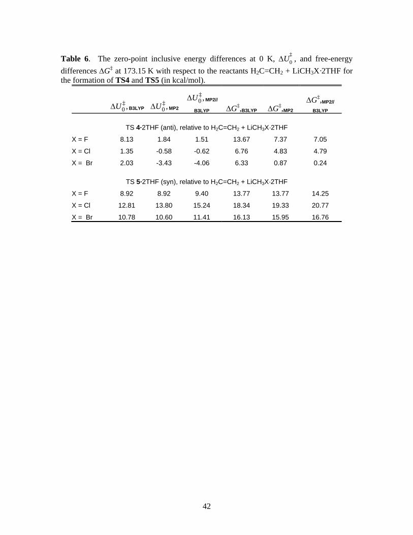
significant as shown in Table 6. When compared to the gas phase (Table 2), THF solvation
appears to uniformly lower the energy of TS 4·2THF for anti elimination relative to the reactants
while raising the energy of the transition state TS 5·2THF for syn elimination. This is likely a
result of increased stability of the separated ions X– and Li+ in the presence of a strongly
coordinating polar solvent while the direct formation of LiX from TS 5 is more favorable in the
Running title: Cyclopropanation Reactions of Halomethyllithium Carbenoids
18
gas phase. The structures of TS 4·2THF and TS 5·2THF are shown in Supporting Information.
Note that, as in the case of Table 2, Table 6 reports the energies of the transition states for anti
and syn eliminations relative to the starting materials H2C=CH2 + LiCH2X·2THF. The
energetics relative to the reactive intermediate 3·2THF is easily recovered by subtracting from
these numbers the appropriate values given in Table 5 for the formation of 3·2THF. So, for
example, the ‡0,MP2U∆ of TS 4·2THF for X = Br is –3.43 kcal/mol relative to H2C=CH2 +
LiCH2X·2THF but –3.43 – (–18.26) = 14.83 kcal/mol relative to 3·2THF.
*** Suggested location of Table 6 ***
Another aspect of Tables 5 and 6 deserves comment, namely, the rather large differences
in the B3LYP and MP2 energy differences in the formation of TS 2·2THF and 3·2THF (Table 5),
and the energy of TS 4·2THF relative to the reactants (Table 6). In these cases, the MP2 and
MP2//B3LYP results are reasonably close, indicating that the B3LYP geometries are close to
those found by MP2, but the B3LYP functional yields a rather different energy.
As mentioned above, we also examined the reactions of monosolvated monomers in the
case of X = Cl at the B3LYP/6-31+G(d) level, including IRC calculations of reaction paths.
Except for the discovery of the pre-reactive complex for the stepwise reaction (See Eq. 7), the
results were qualitatively similar to those reported by KZP for X = F in DME, and the gas phase
results reported above, in this work. Since the monosolvated monomers are unstable relative to
the disolvated species (see Eq. 8), they are not discussed further.
Running title: Cyclopropanation Reactions of Halomethyllithium Carbenoids
19
D. Reactions of THF solvated dimers with ethylene
The dimeric halomethyllithium carbenoids exist largely as the tetrasolvates in THF
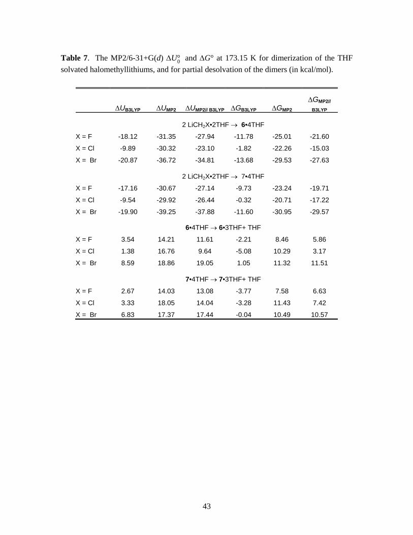
solution.38 On the other hand, dissociation to the trisolvated forms is reasonably facile. The ∆U°0
and ∆G° for the following equilibria at 173.15 K are summarized in Table 7.
2 LiCH2X•2THF → (LiCH2X)2•4THF (9)
(LiCH2X)2•4THF → (LiCH2X)2•3THF + THF (10)
*** Suggested location of Table 7 ***
The most striking aspects of Table 7 are the large differences between B3LYP and MP2
results and the less dramatic, but significant, differences between MP2 and MP2//B3LYP results.
The B3LYP method yields qualitatively different results for the dimerization free energies,
indicating that the trisolvated species are more stable. The appreciable differences between MP2
and MP2//B3LYP energies indicate non-negligible differences in the predicted equilibrium
structures.
The following analysis is presented to substantiate the last statement. The three panels of
Figure 8 show the equilibrium structures of 6•4THF for X = F obtained from (a) B3LYP/6-
31+G(d) starting with the HF/6-31+G(d) equilibrium structure, (b) MP2/6-31+G(d) starting with
the structure in panel (a), and (c) the B3LYP/6-31+G(d) structure obtained from the structure in
panel (b). The Li-O distances are quite comparable in all cases, suggesting that the B3LYP and
MP2 descriptions of the coordination of THF to the Li atoms are quite comparable. On the other
hand, there are significant differences between the hexagonal rings of the dimer obtained from
the two treatments. We note the Li-Li, the F-F, and the C-C distances in particular. Panel (c)
shows that the DFT equilibrium structure can be recovered from the MP2 structure quite
accurately, eliminating the possibility that there may be local minima in the energy landscape
Running title: Cyclopropanation Reactions of Halomethyllithium Carbenoids
20
corresponding to both structures. We have examined the case of X = Cl and found similar
behavior.
*** Suggested location of Fig 8 ***
The structural differences are reflected in the differences in the MP2 energy between the
structures in panels (b) and (a) id Fig. 8, which we designate as EMP2//MP2 – EMP2//B3LYP. These
differences are –6.23 kcal/mol for X = F, –11.16 kcal/mol for X = Cl, and –3.78 kcal/mol for X =
Br. The analogous energy differences for 7•4THF for X = F, Cl and Br are, respectively, –6.35,
–7.32, and –3.25 kcal/mol respectively. The energy differences for the trisolvated species range
from –3.15 kcal/mol for 7•4THF (X=Br) to –5.23 kcal/mol for 7•4THF (X=F), once again the
MP2//B3LYP energy being always higher than the MP2//MP2 energy. At the same time,
EMP2//MP2 – EMP2//B3LYP for THF is only –0.17 kcal/mol. It is easy to see now that these absolute
energy differences quoted above account for the large differences between the ∆U°0 and ∆G°
differences between MP2 and MP2//B3LYP levels of theory in Table 7. On the other hand, the
difference EMP2//MP2 – EMP2//B3LYP for gas phase dimers 6 and 7 are very small, ranging from –
0.22 kcal/mol for 6 (X=F) to –1.1 kcal/mol for 7 (X=Cl). This suggests that the interaction of the
Li with the THF solvent molecules has a significant influence on the structural and energetic
predictions of the two levels of theory for parts of the molecule other than the Li-O bond.
The physically unreasonable prediction of the B3LYP in Table 7, that the trisolvated
species is more stable, leads us to attach more importance to the MP2 results for these cases. The
long range interactions that determine the structural parameters of the dimeric ring are also
among the types of interactions with which the second-generation density functionals, even a
highly successful hybrid functional like B3LYP, have difficulty.39 Therefore, we focus mainly
on MP2 results for solvated species from this point forward, with the exception of Table 11.
Running title: Cyclopropanation Reactions of Halomethyllithium Carbenoids
21
Several attempts were made to locate a TS structure for the concerted insertion reaction
of the tetrasolvated dimer with ethylene, but steric constraints proved to be too hard to overcome.
KZP report tetrasolvated dimeric TS structures in DME solvent,1 which points to yet another
difference in the cyclopropanation reactions of LiCH2X in DME and THF. As mentioned earlier,
it is possible that the more rigid structure of the THF ring and its stronger binding to the Li atom
introduce steric effects not present in the case of more flexible ethereal solvent molecules.
TS structures were successfully located for the reaction of the trisolvated form, which are
labeled as TS 8·3THF and TS 9·3THF for the concerted and stepwise reactions of 6, respectively,
and TS 10·3THF and TS 11·3THF respectively for the analogous reactions of 7. Table 8
summarizes the MP2 free energy changes associated with the reactions. The figures of the TS
structures are provided in the Supporting Information.
*** Suggested location of Table 8 ***
The results tabulated in Table 8 show that, compared to the case of the gas-phase dimers
(Table 4), the barriers are significantly higher for both the concerted and stepwise mechanisms.
For example, the ‡0,MP2U∆ and ‡
MP2G∆ for TS 8 (X=F) for the gas phase dimer 6 are 6.70 and
11.60 kcal/mol, respectively (Table 4), compared to 19.76 and 17.85 kcal/mol respectively in
THF. The barriers for the stepwise reaction also increase for this species, from 23.56 and 29.21
kcal/mol in the gas phase (∆U‡0 and ∆G‡, respectively, Table 4) to 33.46 and 32.68 kcal/mol in
THF. This trend appears to be absent in DME solvent. For that case, KZP report ∆U‡0 for 6 (the
only dimeric form they studied) of 5.9 kcal/mol in gas phase (B3LYP/6-311G(d,p); Figure 3 of
Ref. 1) and 5.8 kcal/mol for the tetrasolvated case (Figure 6 of Ref. 1). However, similar to the
gas phase, the barriers for the stepwise pathway for the solvated dimeric species remain higher
than that for the concerted mechanism in both THF and DME. Thus, combining our results, the
Running title: Cyclopropanation Reactions of Halomethyllithium Carbenoids
22
experimentally observed preference for the concerted pathway can be confirmed by
computational results in DME and THF for the dimeric species.
Another significant difference between the behavior of gas phase and THF-solvated
dimers is that the formation of intermediate 3·2THF according to
H2C=CH2 + (Li-CH2-X)2·4THF → Li-(CH2)3-X·2THF + Li-CH2-X·2THF (11) 3·2THF
is thermodynamically unfavorable at 173.15 K, as shown in Table 9. Therefore, in additional to
the higher barriers, the stepwise mechanism may be frustrated in THF by the relative instability
of the required reactive intermediate. KZP did not study the carbometalation pathway for the
DME-solvated dimer and, therefore, a comparison cannot be made.
*** Suggested location of Table 9 ***
The MP2 free energy profiles of the monomeric and dimeric LiCH2X in THF solvent are
presented in Figure 11. For clarity, only dimer 6 is shown. As can be ascertained from Tables 7-
9, the energy profile for dimer 7 is not qualitatively different.
*** Suggested location of Fig 9 ***
E. Reactions of gas phase and THF solvated tetramers with ethylene
The formation of the tetramer from the dimer is highly favored in the gas phase. Since
dimers are much more stable than the monomers, we examine the formation of tetramers from
the dimers, taking dimer 6 as a representative.
2 (LiCH2X)2 → (LiCH2X)4 (12) 6
The relevant ∆U°0 and ∆G° data are summarized in Table 10. Note that tetramerization is even
more favorable in nonpolar solvents, in which case each free energy change shown will further
Running title: Cyclopropanation Reactions of Halomethyllithium Carbenoids
23
decrease by 2 × 0.91 = 1.82 kcal/mol at 173.15 K (see the paragraph above Eq. 6). Also
summarized in Table 10 are the ∆U‡0 and ∆G‡ for the concerted and stepwise reactions,
proceeding through TS 12 and TS 13, respectively:
H2C=CH2 + (LiCHX)4 → TS 12 (concerted mechanism) (13)
H2C=CH2 + (LiCH2X)4 → TS 13 (stepwise mechanism) (14)
The MP2 structures for the tetramer, TS 12, and TS 13 are given in Figure 10. Simply as
a visual aid, the tetramer is visualized in these figures as two units of dimer 6. While the
structure of TS 12 in the vicinity of the alkene double bond and the methylene group being
inserted into it are comparable to TS 1 and TS 8, the tetrameric transition state for the stepwise
insertion, TS 13, does not have a four-membered structure similar to the analogous reactions of
the monomer (Figure 2, TS 2) and dimer 6 (Figure 6, TS 10).
*** Suggested location of Fig. 10 ***
*** Suggested location of Table 10 ***
The ‡0,B3LYPU∆ for the concerted and stepwise mechanisms of 4.53 and 30.94 kcal/mol,
respectively, for X = F compares well with the 4.9 and 30.8 kcal/mol reported by KZP (Figure
3(C) of Ref. 1) for the same processes. In the case of the tetramers also, a very clear preference
for the concerted mechanism is observed.
We also examined the energetics of tetramerization in THF solvent, relative to the
tetrasolvated dimer 6. For steric reasons, it appears unlikely that the primary solvation sphere of
the tetramer will contain more than one THF coordinated to each lithium, an assumption
supported by x-ray structures of other tetrameric organolithium species.40
2 (LiCH2X)2·4THF → (LiCH2X)4·4THF + 4THF (15)
Thus, Table 11 reports
the energy changes associated with the process
Running title: Cyclopropanation Reactions of Halomethyllithium Carbenoids
24
6 In Table 11, we also include B3LYP and MP2//B3LYP results to show, for the final time, the
great discrepancy between B3LYP and MP2 geometries and energies when coordinated THF
molecules are involved.
*** Suggested location of Table 11 ***
As in the case of Table 7, Table 11 displays large discrepancies between the B3LYP and
MP2, and also between MP2 and MP2//B3LYP energies, implying that the geometries found by
B3LYP are significantly different from those obtained by MP2. The energy differences EMP2//MP2
– EMP2//B3LYP for the solvated tetramers for X = F, Cl, and Br are, respectively, –7.11, –9.04, and
–4.68 kcal/mol. The energy differences noted earlier for the tetra-solvated dimeric species get
magnified by a factor of 2 in Eq. (15). The combined differences in absolute energies are
sufficient to account for the large differences between the MP2 and MP2//B3LYP results
tabulated in Table 11. As one would expect from Table 10, the differences EMP2//MP2 –
EMP2//B3LYP for the gas phase tetramers are quite small, ranging from –0.16 kcal/mol for X = F to
–1.42 kcal/mol for X = Cl.
In striking contrast to the gas phase or nonpolar solvents (Table 10), the ∆U°0 values in
Table 11 shows that the formation of the tetramer is endoergic and its formation is
thermodynamically unfavorable at the MP2 level of theory. This dramatic reversal of gas-phase
thermodynamics appear to be primarily due to the steric effects introduced by the explicit
coordination of THF ligands. This conclusion is suggested by comparing the MP2 free energies
in Table 11 to the results of taking solvent effects into account through the Polarizable
Continuum Model (PCM)41,42 for the dimer and tetramer, shown in Table 12. The PCM
calculations for Table 12 were done for dimer 6 and the tetramer at gas phase MP2 geometries
Running title: Cyclopropanation Reactions of Halomethyllithium Carbenoids
25
using HF/6-31+G(d) and UAHF radii. Table 12 shows the gas phase MP2G∆ for Eq. (12), adds
the solvation free energy, and includes the correction for changing the standard state from 1 atm
at 173.15 K (1 mol/14.21 L) to 1 mol/L that was mentioned in Section 2. In spite of the slight
destabilization of the tetramer relative to the dimer due to solvation, this treatment still predicts
that tetramerization is a thermodynamically favorable process in a solvent with ε = 7.85.
Therefore, the positive MP2G∆ for tetramerization in Table 11 must be the result of further
destabilization of the tetramer due to steric effects which, of course, are not described by
continuum solvation models.
Since MP2 results indicate that the dominant species of LiCH2X in THF solution is likely
to be the dimer, and also because of the computational difficulties associated with treating such
large systems at MP2 level of theory (72 atoms for the tetrasolvated tetramer), we did not
examine the barrier heights for the reactions of the tetrasolvated tetramer with ethylene.
*** Suggested location for Table 12 ***
F. Reactions of gas phase dimers with dimethylbutene
In this Section, we report on the reactions of (LiCH2X)2 with 2,3-dimethyl-2-butene,
(CH3)2C=C(CH3)2, abbreviated as DMB for convenience. These studies were undertaken to
examine whether the conclusions drawn from the preceding sections and the studies of KZP were
applicable only to ethylene.
The transition state structures for the direct and stepwise pathways are given in Figure 11
for the representative case of X = Br, and are oriented so that comparisons can be made with the
structures of transition states 8 and 9 for ethylene in Figures 6 and 7. The concerted mechanism
involving dimer 6 passes through TS 14 while dimer 7 undergoing the same reaction passes
through TS 15. Many structural aspects of the transition states 14 and 15 are comparable to
Running title: Cyclopropanation Reactions of Halomethyllithium Carbenoids
26
analogous structures involving ethylene, namely, TS 8 (Figure 6) and 9 (Figure 7). The stepwise
reactions of dimers 6 and 7 with DMB pass through transition states 16 and 17, respectively,
which are structurally similar to TS 10 (Figure 6) and TS 11 (Figure 7). As in the case of
ethylene, we were able to identify relatively stable pre-reactive complexes in which one of the Li
atoms of the dimer interacted strongly with the alkene double bond. In keeping with the
numbering conventions adopted earlier, these are designated as 16′ and 17′, respectively for
dimers 6 (leading to TS 16) and 7 (leading to TS 17), and are shown in Figure 13. Structurally,
these are similar to the structures for 10′ (Figure 6) and 11′ (Figure 7).
*** Suggested location for Fig. 11 ***
The zero-point inclusive relative (with respect to reactants) energies at 0 K, ∆U°0 , and
relative free-energies at 173.15 K and standard pressure, ∆G°, for the processes studied are
summarized in Table 13. The analogous results for ethylene are given in Table 4. It is clear
from Table 13 that the concerted mechanism is clearly preferred over the stepwise pathway at all
levels of theory examined. The barriers for the concerted pathway are generally lower than those
for ethylene (compare to TS 8 and TS 9 in Table 4), especially in the case of dimer 7, while those
for the stepwise pathway are higher, indicating an even stronger preference for the direct
pathway compared to that of ethylene.
*** Suggested location for Table 13 ***
A couple of “anomalies” to be noted in Table 13 are the negative values for 0U∆ at the
MP2 and MP2//B3LYP levels of theory for TS 15 for the case of X = Br. To investigate these
further, we performed MP2 level IRC calculations for both dimers. These calculations reveal
that as the carbenoid dimer approaches the alkene to form transition states 14 or 15 (dimer 6 or 7,
respectively) one of the lithium atoms starts to interact with one of the sp3 carbons of the DMB.
Running title: Cyclopropanation Reactions of Halomethyllithium Carbenoids
27
These interactions are long-range and appear to be electrostatic in nature. Figure 12 shows the
MP2/6-31+G(d) structures of transition states 14 and 15 from perspectives that make it easier to
visualize these interactions, along with charges fitted to the electrostatic potential using the
Merz-Singh-Kollman algorithm.43
*** Suggested location for Fig. 12 ***
In the case of bromo dimer 7, the IRC shows clear indications that the interaction gives
rise to a weak pre-reactive complex, since its energy becomes even more negative relative to the
reactants for negative values of the reaction coordinate. As shown in Figure 13, a “physically
reasonable” interpolation from the last calculated point on the IRC to the asymptotic reactants at
E = 0 kcal/mol suggest that the minimum energy of the IRC may be around –3.8 kcal/mol at a
value of the reaction coordinate of approximately –2.4. The formation of this complex is
sufficient to lower the zero-point energy inclusive reaction barriers ‡0U∆ for TS 15 to the small
negative values reported in Table 13.
*** Suggested location for Fig. 13 ***
The interactions responsible for this pre-complex formation appear to be much weaker in
the case of dimer 6. A simplistic electrostatic potential calculation can be done to estimate the
strength of the interactions using the ESP fitted charges and Li-C distances shown in Fig. 12
(~ q1q2/r). This shows that the electrostatic potential in the case of TS 14 for X = Br (dimer 6) is
only 62% as strong as that in TS 15 (dimer 7). The IRC leading to the reactants from TS 14 for
X = Br, interpolated as described earlier and shown in Fig. 13, suggests the presence of a shallow
minimum of about –0.50 kcal/mol relative to the reactants at a value of the reaction coordinate of
approximately –3.0. The simplistic electrostatic potential calculation mentioned above also
shows that similar interactions between Li and the sp3 carbons of the alkene in the case of dimer
Running title: Cyclopropanation Reactions of Halomethyllithium Carbenoids
28
7 for X = Cl is about 71% as strong as that in TS 15 (dimer 7) for X = Br. The MP2/6-31+G(d)
IRC for the chloro dimer 7 (TS 15) offers strong hints that it may fall to small negative energies
with respect to asymptotic reactants, but convergence difficulties for large enough negative
values of the reaction coordinate prevented us from confirming this. When interpolated as
before, the IRC shows a minimum of about –0.60 kcal/mol at a value of the reaction coordinate
of approximately –4.0, as shown in Fig. 13.
The MP2/6-31+G(d) IRC calculation for both fluoro dimers could not be extended far
from the transition states towards the reactants because of convergence difficulties. However,
the overall shape of the IRC that could be mapped out provided no hints of pre-reactive complex
formation in either case. Whether or not the relative energy along the IRC falls below zero for
negative values of the reaction coordinate (the “reactant” side of the barrier), the relatively
stronger long-range interactions in the case of dimers 7 may be responsible for lowering the
reaction barriers for forming TS 15 for all three halogens compared to those for the formation of
TS 14 from dimer 6. It is possible that similar interactions may cause the barriers for the
concerted mechanism to remain low for longer chain alkenes, thus favoring the concerted
mechanism in general for the insertion of a methylene group into a carbon-carbon double bond.
Although hydrogens are not shown in the structures in Fig. 12 for the sake of clarity, we
also considered the interactions between the hydrogens bonded to the sp3 carbon which interacts
with the lithium in Fig. 14. The Merz-Singh-Kollman algorithm assigns partial positive charges
(+0.10 to +0.16 depending on the dimer and the halogen) to these hydrogens and none of them
are directed towards the Li atom. However, metal-hydrogen interactions are common in
organolithium chemistry and they may also play a role in determining the relative strengths of
the long-range interactions discussed above.
Running title: Cyclopropanation Reactions of Halomethyllithium Carbenoids
29
Even though B3LYP transition state structures are qualitatively similar to those predicted
by MP2, the IRC’s calculated using B3LYP/6-31+G(d) show no indication that pre-reactive
complexes are being formed in the case of either dimer for any halogen. The electrostatic
interactions are strongest in the case of TS 15 for X = Br in the case of DFT also, but the IRC in
this case is such that the distance between the Li of the dimer and the sp3 carbons of DMB
increases rapidly as the reaction coordinate assumes negative values. This may be a reflection of
the relative inability of B3LYP to account for long-range non-bonded interactions,39 on which
we commented earlier, in connection with THF-solvated structures.
Given these gas phase results for DMB and their qualitative similarity in essential aspects
to the gas phase results for ethylene (concerted reaction significantly favored over the stepwise
mechanism), we expect the mechanisms of DMB reacting with the carbenoid dimers in THF
solution to also be qualitatively similar to those observed in the case of ethylene.
4. Summary and Conclusions This paper describes a detailed computational study of the cyclopropanation reactions of
halomethyllithiums. Two mechanisms have been proposed for these reactions, namely the direct
insertion of CH2 into the alkene double bond,2,3,5 (methylene transfer) and a stepwise mechanism
involving carbolithiation.4 Although experimental evidence for the concerted mechanism is
strong, it has been difficult to completely rule out the stepwise pathway. Until recently,
computational chemistry was also not very helpful because calculations were limited to
monomeric species in the gas phase, which have yielded comparable reaction barriers for both
processes.6,7 One novelty of the work of KZP1 and the present report is the consideration of the
reactions of the halomethyllithium dimers and tetramers which are significantly more stable than
the monomers and thus expected to be the dominant reagent species. The calculated reaction
Running title: Cyclopropanation Reactions of Halomethyllithium Carbenoids
30
barriers for the reactions of dimers show a clear preference for the concerted pathway in the gas
phase, non-polar solvents, and in two polar solvents – DME (Ref. 1), and THF (present work).
In the case of tetramers, there is a clear preference for the concerted reaction in the gas phase and
in non-polar solvents. The computational challenges of dealing with a fully solvated tetramer
prevented us from calculating barrier heights for the reaction in THF but, based on the
comparison of the barrier heights for the gas phase and THF-solvated dimers, it is reasonable to
expect that the barrier heights for the solvated tetramer for the concerted reaction will be
comparable to, or lower than that for the gas phase tetramer, and that the barrier height for the
stepwise pathway will be comparable or higher than that for the gas-phase tetramer. Thus
consideration of the aggregated species in computational modeling establishes a clear preference
for direct methylene transfer mechanism for the cyclopropanation reactions of
halomethyllithiums. The work of KZP and the present report thus resolve a question that has
been open since the proposal of the two-step pathway by Hoberg in 1962 and its refutation by
Burger and Huisgen in 1970, both on the basis of experimental evidence.
Our work shows that ethylene dimer 7, which was not investigated by KZP, provides a
slightly lower energy pathway for the concerted gas phase reaction (Table 4). In the reactions of
DMB with the dimeric carbenoids in the gas phase, reported here for the first time, the reaction
barriers for the concerted gas phase reactions of dimer 7 are significantly lower than those for
dimer 6 (Table 13), thanks to long-range interactions between the approaching lithium carbenoid
and the sp3 carbons of the butene. These interactions and their tendency to lower the reaction
barriers for the concerted reaction offer strong indication that the preference for the concerted
pathway observed in the case of ethylene and dimethylbutene may be generalized to other
alkenes.
Running title: Cyclopropanation Reactions of Halomethyllithium Carbenoids
31
The greater polarity of THF (ε = 7.85) compared to DME (ε = 4.34) and the rigidity of
the ring-structure gives rise to interesting differences in steric and energetic effects. The
carbolithiation pathway of bis-THF solvated monomers and dimers do not appear to pass through
pre-reactive complexes while Ref. 1 indicates that such complexes are formed in DME. The
tetrasolvated dimers in THF appear to have difficulty forming tetrasolvated transition states
(trisolvated transition states were easily identified) because of the strongly coordinated THF
ligands while KZP report tetrasolvated transition states in DME. In connection to Table 8, we
observed that, compared to the gas phase reactions, THF solvation increased the barrier heights
for both the concerted and carbolithiation pathways for dimers 6 and 7. In contrast, at least for
dimer 6 and the X = F case, KZP report that reaction barriers in DME are comparable to those in
the gas phase.
Since the halogens are not directly involved in the reaction, the significant differences in
electronegativity and ionic radii of the three halogens play only an indirect role in determining
the energetic of the reaction. Reaction barriers for X = F and Br are found to be generally lower
than those for X = Cl but for different reasons. In the case of X = F, the great affinity of Li for F
is responsible for the formation of transition states which are stabilized by the interaction of Li
and F while the lower barriers in the case of X = Br are related to the relatively weaker bonding
of Br to the methyl carbon and Li. The affinity of the Li and F towards each other is reflected in
the ∆G° for the formation of the Li-CH3-X⋅LiX mixed aggregates. At the B3LYP and MP2
levels, the ∆G° for the formation of the fluoro mixed aggregates is more negative by about 10
kcal/mol than for the bromo, with the chloro falling in between. In the concerted reactions of
DMB, long-range interactions between the carbenoid dimer 7 and the sp3 carbons of the alkene
lead to the formation of weak pre-reactive complexes in the case of the relatively easily
Running title: Cyclopropanation Reactions of Halomethyllithium Carbenoids
32
polarizable Br. The strong interaction of F with Li and its significantly lower polarizability
appear to weaken such long-range interactions with carbon in the case of X = F. Once again, the
X = Cl case falls in between, as discussed in the previous section.
Structure optimization using B3LYP followed by single-point MP2 calculation
(MP2//B3LYP) appears to be a highly economical and reliable procedure in the case of gas phase
molecules and an acceptable compromise in the case of solvated monomers. In these cases, the
energy differences calculated from MP2-optimized structures are quite close to the MP2//B3LYP
results. However, the non-covalent and weak interactions responsible for dimerization and the
dipole interactions in the solvated species appear to cause problems for B3LYP. The analysis
presented in Fig. 8 and the related discussion reveals that the B3LYP and MP2 descriptions of
the coordination of THF to the Li atoms are quite similar. However, the presence of the solvent
molecules leads the two methods to predict equilibrium structures with large structural
differences (see Tables 7 and 11) for parts of the molecule other than the Li-O bond. In these
cases, contradictory predictions of relative stabilities for solvated dimers by B3LYP and MP2
suggest that the MP2 predictions are more reliable.
The comparison of PCM vs. explicit solvation by THF ligands (Tables 11 and 12) offer
support to the statement made in the Introduction that explicit inclusion of solvent molecules is
often necessary in organolithium chemistry to describe the steric effects in the primary solvation
sphere. In this context, the apparent failure of B3LYP at predicting THF-coordinated structures
comparable to those obtained with MP2, at considerably greater computational cost, is rather
disheartening. We are currently exploring the performance of the most recent generation of
DFT functionals39 for these systems.
Running title: Cyclopropanation Reactions of Halomethyllithium Carbenoids
33
Acknowledgments
This work was supported in part by NSF grant INT-0454045, CHE-0643629, and DMR-
0414903. This research used resources of the National Energy Research Scientific Computing
Center, which is supported by the Office of Science of the U.S. Department of Energy under
Contract No. DE-AC03-76SF00098. The use of the IBM p5-575 computers provided by the
Louisiana Optical Network Initiative (LONI) is gratefully acknowledged.
Supporting Information Available: Optimized MP2 structures, energies of all reactants,
products, and TS structures are provided in PDF format. Calculations of ∆E, ∆U°0 and ∆G° at the
HF, B3LYP, MP2, MP2//B3LYP levels for the results reported in this paper are provided in the
form of an Excel file. This material is available free of charge on the web at
http://www.csj.jp/journals/bcsj/.
Running title: Cyclopropanation Reactions of Halomethyllithium Carbenoids
34
References 1 Z. Ke, C. Zhao, D. L. Phillips, J. Org. Chem. 2007, 72, 848.
2 H.E. Simmons, R.D. Smith, J. Am. Chem. Soc. 1958, 80, 5323.
3 H.E. Simmons, R.D. Smith, J. Am. Chem. Soc. 1959, 81, 4256.
4 H. Hoberg, Leibigs Ann. Chem. 1962, 656, 1.
5 U. Burger, R. Huisgen, Tetrahedron Lett. 1970, 3049.
6 H. C. Stiasny, R. W. Hoffmann, Chem. Eur. J. 1995, 1, 619.
7 M. Nakamura, A. Hirai, E. Nakamura, J. Am. Chem. Soc. 2003, 125, 2341.
8 H. Hermann, J. C. Lohrenz, A. Kuhn, G. Boche Tetrahedron, 2000, 56, 4109.
9 C. Y. Zhao, D. Q. Wang, D. L. Phillips, J. Am. Chem. Soc. 2002, 124, 12903.
10 D. Q. Wang, D.L. Phillips, W. H. Fang, Organometallics, 2002, 21, 5901.
11 C. Y. Zhao, D. Q. Wang, D. L. Phillips, J. Am. Chem. Soc. 2003, 125, 15200.
12 D. Q. Wang, C. Y. Zhao, D. L. Phillips, J. Org. Chem. 2004, 69, 5512.
13 Z. Ke, Y. Zhou, H. Gao, C. Y. Zhao, D. L. Phillips, Chem. Eur. J. 2007, 13, 6724.
14 L. M. Pratt, N. V. Nguyen, O. Kwon Chem. Lett. 2009, 38, 574.
15 V. Capriati, L. Degennaro, R. Favia, S. Florio, R. Luisi, Org. Lett. 2002, 4, 1551.
16 D. M. Hodgson, N. J. Reynolds, S. J. Coote, Org. Lett. 2004, 6, 4187.
17 S. H. Wiedemann, A. Ramirez, D. B. Collum, J. Am. Chem. Soc. 2003, 125, 15893.
18 T. Satoh, Chem. Rev. 1996, 96, 3303.
19 P. J. Campos, D. Sampedro, M. A. Rodriguez, Organometallics 1998, 17, 5390.
20 L. M. Pratt, B. Ramachandran, J. D. Xidos, C. J. Cramer, D. G. Truhlar, J. Org. Chem. 2002,
67, 7607.
21 L. M. Pratt, I. M. Khan, J. Comp. Chem. 1995, 16, 1067.
Running title: Cyclopropanation Reactions of Halomethyllithium Carbenoids
35
22 F. E. Romesberg, D. B. Collum, J. Am. Chem. Soc. 1992, 114, 2112.
23 J. L. Rutherford, D. B. Collum, J. Am. Chem. Soc. 2001, 123, 199.
24 C. Gonzalez, H. B. Schlegel, J. Chem. Phys. 1989, 90, 2154.
25 C. Gonzalez, H. B. Schlegel, J. Phys. Chem. 1990, 94, 5523.
26 L. M. Pratt, S. Merry, S. C. Nguyen, P. Quan, B. T. Thanh, Tetrahedron, 2006, 62, 10821.
27 M. J. Frisch, G. W. Trucks, H. B. Schlegel, G. E. Scuseria, M. A. Robb, J. R. Cheeseman, J.
A. Montgomery Jr., T. Vreven, K. N. Kudin, J. C. Burant, J. M. Millam, S. S. Iyengar, J.
Tomasi, V. Barone. B. Mennucci, M. Cossi, G. Scalmani, N. Rega, G. A. Petersson, H.
Nakatsuji, M. Hada, M. Ehara, K. Toyota, R. Fukuda, J. Hasegawa, M. Ishida, T. Nakajima,
Y. Honda, O. Kitao, H. Nakai, M. Klene, X. Li, J. E. Knox, H. P. Hratchian, J. B. Cross, C.
Adamo, J. Jaramillo, R. Gomperts, R. E. Stratmann, O. Yazyev, A. J. Austin, R. Cammi, C.
Pomelli, J. W. Ochterski, P. Y. Ayala, K. Morokuma, G. A. Voth, P. Salvador, J. J.
Dannenberg, V. G. Zakrzewski, S. Dapprich, A. D. Daniels, M. C. Strain, O. Farkas, D. K.
Malick, A. D. Rabuck, K. Raghavachari, J. B. Foresman, J. V. Ortiz, Q. Cui, A. G. Baboul,
S. Clifford, J. Cioslowski, B. B. Stefanov, G. Liu, A. Liashenko, P. Piskortz, I. Komaromi, R.
L. Martin, D. J. Fox, T. Keith, M. A. Al-Laham, C. Y. Peng, A. Nanayakkara, M.
Challacombe, P. M. W. Gill, B. Johnson, W. Chen, M. W. Wong, C. Gonzalez, J. A. Pople,
GAUSSIAN 03 Gaussian, Inc., Pittsburgh. PA, 2003.
28 C. Gonzalez and H. B. Schlegel, J. Chem. Phys. 1989, 90, 2154; J. Phys. Chem. 1990, 94,
5523.
29 J. D. Thompson, C. J. Cramer, D. G. Truhlar, J. Chem. Phys. 2003, 119, 1661.
30 L. M. Pratt, V. N. Nguyen, B. Ramachandran, J. Org. Chem., 2005, 70, 4279.
Running title: Cyclopropanation Reactions of Halomethyllithium Carbenoids
36
31 U. P. Govender, T. M. Letcher, S. K. Garg, J. C. Ahluwalia, J. Chem. Eng. Data 1996, 41,
147.
32 L. M. Pratt, A. Streitwieser, J. Org. Chem., 2003, 68, 2830.
33 L. M. Pratt, S. Mogali, K. Glinton, J. Org. Chem., 2003, 68, 6484.
34 L. M. Pratt, R. Mu, J. Org. Chem., 2004, 69, 7519.
35 L. M. Pratt, Bull. Chem. Soc. Japan, 2005, 78, 890.
36 L. M. Pratt, N. V. Nguyen, L. T. Le, J. Org. Chem., 2005, 70, 2294.
37 L. M. Pratt, N. V. Nguyen, J. Phys. Chem. A 2006, 110, 687.
38 L. M. Pratt, D. H. Phan-Tran, P. T. T Tran, N. V. Nguyen, Bull. Chem. Soc. Japan, 2007, 80,
1587.
39 Y. Zhao, D. G. Truhlar, J. Chem. Theory and Comput. 2007, 3, 289.
40 R. Amstutz, W. B. Schweizer, D. Seebach, J. D. Dunitz, Helv. Chim. Acta 1981, 64, 2617.
41 M. T. Cancès, B. Mennucci, and J. Tomasi, J. Chem. Phys. 1997, 107, 3032; M. Cossi, V.
Barone, B. Mennucci, and J. Tomasi, Chem. Phys. Lett. 1998, 286, 253; B. Mennucci and
J.Tomasi, J. Chem. Phys. 1997, 106, 5151.
42 M. Cossi, G. Scalmani, N. Rega, and V. Barone, J. Chem. Phys. 2002, 117, 43.
43 U. C. Singh and P. A. Kollman, J. Comp. Chem. 1984, 5, 129; B. H. Besler, K. M. Merz Jr.,
and P. A. Kollman, J. Comp. Chem. 1990, 11, 431.
37
Table 1. The zero-point inclusive energy differences at 0 K, U°0 and free-energy
differences G° at 173.15 K with respect to the reactants for the processes summarized in Eqs. (1) and (2) (in kcal/mol).
U°0,B3LYP U°0,MP2U°0,MP2
//B3LYPU°0,CCSD(T)
//MP2 G°B3LYP G°MP2G°MP2//
B3LYP
H2C=CH2 + LiCH3X TS 1
X = F 6.47 7.83 7.87 7.73 11.44 12.80 12.84
X = Cl 5.56 8.50 8.04 7.09 10.49 13.42 12.96
X = Br 5.42 6.60 6.49 5.90 10.49 11.67 11.56
H2C=CH2 + LiCH3X 2
X = F -8.60 -10.18 -10.24 -10.14 -4.46 -6.04 -6.10
X = Cl -8.88 -11.03 -11.11 -10.89 -4.66 -6.81 -6.89
X = Br -9.49 -11.63 -11.71 -11.54 -4.92 -7.05 -7.14
H2C=CH2 + LiCH3X TS 2
X = F 4.11 7.06 6.93 8.87 9.38 12.34 12.20
X = Cl 6.56 6.39 6.08 9.07 12.14 11.97 11.66
X = Br 6.16 6.58 6.47 9.53 11.72 12.14 12.03
H2C=CH2 + LiCH3X 3
X = F -23.07 -27.43 -27.43 -24.29 -17.40 -21.76 -21.76
X = Cl -15.41 -22.18 -22.22 -18.71 -9.65 -16.41 -16.45
X = Br -15.08 -20.52 -20.47 -16.92 -9.28 -14.72 -14.66
H2C=CH2 + LiCH3X Cyclopropane + LiX
X = F -53.39 -63.74 -63.77 -56.94 -53.14 -63.49 -63.52
X = Cl -51.17 -59.86 -60.56 -54.59 -50.95 -59.63 -60.33
X = Br -48.32 -58.63 -58.94 -53.15 -48.13 -58.43 -58.75
38
Table 2. The zero-point inclusive energy differences at 0 K, U‡
0 , and free-energy
differences G‡ at 173.15 K with respect to the reactants H2C=CH2 + LiCH3X for the formation of TS4 and TS5, as outlined in Eq. (3) (in kcal/mol).
‡0 ,U B3LYP
‡0 ,U MP2
‡0 ,U MP2//
B3LYP
‡0 ,U CCSD(T)//
MP2 G‡,B3LYP G‡,MP2G‡,MP2//
B3LYP
TS 4 (anti), relative to H2C=CH2 + LiCH3X
X = F 19.45 14.52 14.29 20.32 24.85 19.92 19.69
X = Cl 10.46 9.96 9.62 13.76 15.88 15.38 15.04
X = Br 9.91 5.61 5.29 10.29 15.43 11.14 10.82
TS 5 (syn), relative to H2C=CH2 + LiCH3X
X = F 0.37 2.94 3.38 4.18 5.52 8.09 8.54
X = Cl 4.82 9.55 9.29 8.72 10.16 14.89 14.63
X = Br 5.15 8.61 8.83 8.06 10.65 14.11 14.33
39
Table 3. The U°0 and G° at 173.15 K for the dimerization of LiCH3X in the gas phase
(in kcal/mol).
U°0,B3LYP U°0,MP2U°0,MP2//
B3LYPU°0,CCSD(T)//
MP2 G°,B3LYP G°,MP2G°,MP2//
B3LYP
2 LiCH3X 6
X = F -44.49 -46.08 -46.12 -46.56 -38.65 -40.25 -40.29
X = Cl -37.55 -43.30 -43.87 -43.19 -31.69 -37.44 -38.01
X = Br -38.08 -42.09 -42.41 -41.99 -32.17 -36.17 -36.50
2 LiCH3X 7
X = F -43.82 -45.09 -45.07 -45.50 -38.21 -39.48 -39.46
X = Cl -35.64 -41.62 -41.95 -41.35 -29.53 -35.51 -35.84
X = Br -37.79 -41.98 -42.29 -41.76 -31.43 -35.61 -35.93
40
Table 4. The U°0 and G° at 173.15 K for the reactions of the gas phase dimers 6 and 7
(in kcal/mol).
U°0,B3LYP U°0,MP2U°0,MP2//
B3LYPU°0,CCSD(T)//
MP2 G°,B3LYP G°,MP2G°,MP2//
B3LYP
H2C=CH2 + 6 TS 8
X = F 6.53 6.70 6.59 5.67 11.44 11.60 11.49
X = Cl 8.87 10.01 11.69 8.35 13.69 14.83 16.51
X = Br 5.87 7.28 7.32 5.74 11.18 12.59 12.62
H2C=CH2 + 6 10
X = F -5.16 -7.89 -7.82 -7.71 -0.76 -3.50 -3.43
X = Cl -4.77 -8.34 -8.19 -8.03 -0.37 -3.94 -3.79
X = Br -2.96 -5.82 -4.97 -5.78 2.06 -0.80 0.06
H2C=CH2 + 6 TS 10
X = F 21.77 23.56 23.56 25.10 27.42 29.21 29.21
X = Cl 23.32 24.62 27.79 27.08 29.24 30.54 33.71
X = Br 17.74 17.43 18.03 19.99 24.04 23.73 24.32
H2C=CH2 + 7 TS 9
X = F 5.30 5.14 5.00 4.19 10.59 10.43 10.29
X = Cl 5.06 7.50 7.00 5.53 9.80 12.23 11.74
X = Br 8.74 5.36 5.28 4.04 13.93 10.55 10.47
H2C=CH2 + 7 11
X = F -6.15 -8.49 -8.56 -8.40 -1.33 -3.67 -3.74
X = Cl -6.46 -9.45 -9.49 -9.21 -1.92 -4.90 -4.94
X = Br -7.56 -10.68 -10.72 -18.89 -2.99 -6.10 -6.14
H2C=CH2 + 7 TS 11
X = F 17.92 19.37 19.29 21.39 23.81 25.26 25.19
X = Cl 18.21 18.72 21.63 21.17 23.78 24.29 27.20
X = Br 15.86 15.53 16.17 18.17 21.66 21.33 21.97
41
Table 5. The zero-point inclusive energy differences at 0 K, U°0 and free-energy
differences G° at 173.15 K with respect to reactants H2C=CH2 + LiCH3X·2THF for the processes summarized in Eqs. (1) and (2) (in kcal/mol).
U°0,B3LYP U°0,MP2U°0,MP2//
B3LYP G°,B3LYP G°,MP2G°,MP2//
B3LYP
H2C=CH2 + LiCH3X.2THF TS 1.2THF
X = F 8.36 7.80 8.33 13.30 12.73 13.27
X = Cl 7.57 7.92 7.76 12.91 13.26 13.10
X = Br 5.64 3.82 3.80 10.26 8.45 8.42
H2C=CH2 + LiCH3X.2THF TS 2.2THF
X = F 13.17 11.40 9.98 18.58 16.80 15.38
X = Cl 17.09 11.89 12.49 23.05 17.85 18.45
X = Br 16.18 10.78 12.15 21.30 15.90 17.27
H2C=CH2 + LiCH3X.2THF 3.2THF
X = F -17.50 -24.19 -23.63 -12.46 -19.15 -18.59
X = Cl -9.27 -18.57 -17.88 -4.09 -13.39 -12.70
X = Br -9.70 -18.26 -17.63 -4.75 -13.30 -12.68
H2C=CH2 + LiCH3X.2THF Cyclopropane + LiX.2THF
X = F -59.11 -65.71 -66.60 -59.40 -66.00 -66.89
X = Cl -58.33 -64.02 -65.35 -58.62 -64.31 -65.65
X = Br -54.59 -62.96 -63.44 -55.76 -64.13 -64.61
42
Table 6. The zero-point inclusive energy differences at 0 K, U‡
0 , and free-energy
differences G‡ at 173.15 K with respect to the reactants H2C=CH2 + LiCH3X·2THF for the formation of TS4 and TS5 (in kcal/mol).
‡0 ,U B3LYP
‡0 ,U MP2
‡0 ,U MP2//
B3LYP G‡,B3LYP G‡,MP2G‡,MP2//
B3LYP
TS 4·2THF (anti), relative to H2C=CH2 + LiCH3X·2THF
X = F 8.13 1.84 1.51 13.67 7.37 7.05
X = Cl 1.35 -0.58 -0.62 6.76 4.83 4.79
X = Br 2.03 -3.43 -4.06 6.33 0.87 0.24
TS 5·2THF (syn), relative to H2C=CH2 + LiCH3X·2THF
X = F 8.92 8.92 9.40 13.77 13.77 14.25
X = Cl 12.81 13.80 15.24 18.34 19.33 20.77
X = Br 10.78 10.60 11.41 16.13 15.95 16.76
43
Table 7. The MP2/6-31+G(d) U°0 and G° at 173.15 K for dimerization of the THF
solvated halomethyllithiums, and for partial desolvation of the dimers (in kcal/mol).
UB3LYP UMP2 UMP2// B3LYP GB3LYP GMP2GMP2//
B3LYP
2 LiCH2X•2THF 6•4THF
X = F -18.12 -31.35 -27.94 -11.78 -25.01 -21.60
X = Cl -9.89 -30.32 -23.10 -1.82 -22.26 -15.03
X = Br -20.87 -36.72 -34.81 -13.68 -29.53 -27.63
2 LiCH2X•2THF 7•4THF
X = F -17.16 -30.67 -27.14 -9.73 -23.24 -19.71
X = Cl -9.54 -29.92 -26.44 -0.32 -20.71 -17.22
X = Br -19.90 -39.25 -37.88 -11.60 -30.95 -29.57
6•4THF 6•3THF+ THF
X = F 3.54 14.21 11.61 -2.21 8.46 5.86
X = Cl 1.38 16.76 9.64 -5.08 10.29 3.17
X = Br 8.59 18.86 19.05 1.05 11.32 11.51
7•4THF 7•3THF+ THF
X = F 2.67 14.03 13.08 -3.77 7.58 6.63
X = Cl 3.33 18.05 14.04 -3.28 11.43 7.42
X = Br 6.83 17.37 17.44 -0.04 10.49 10.57
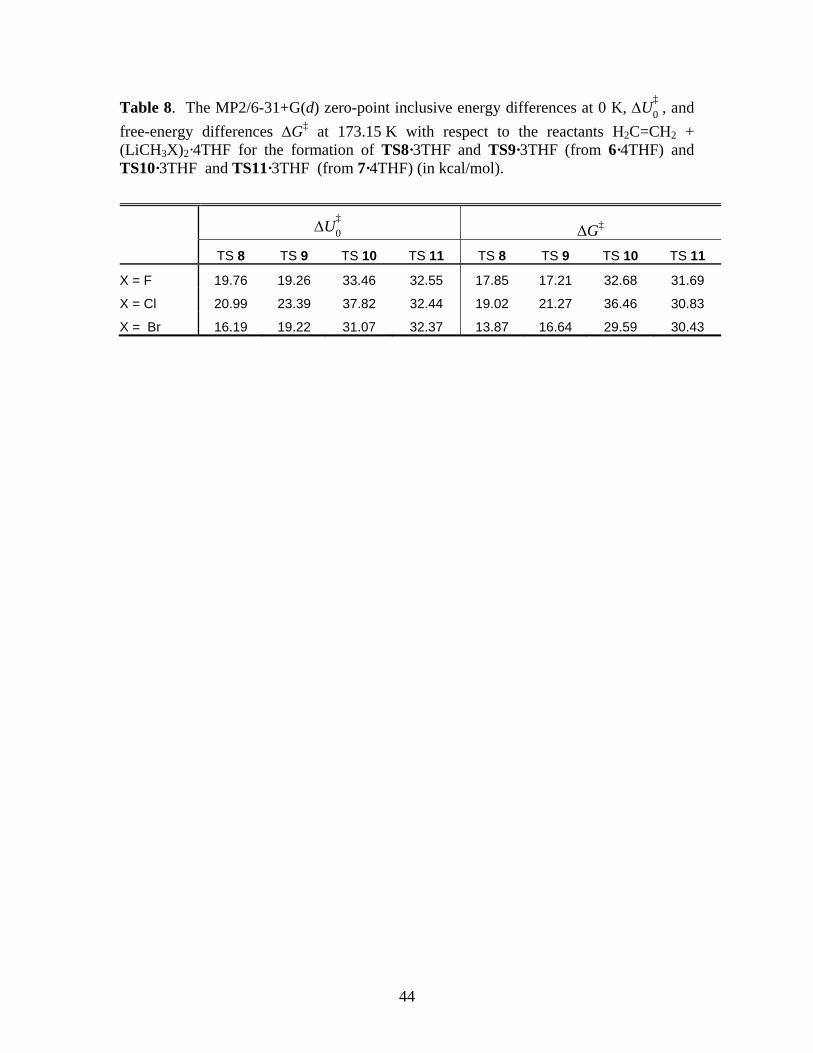
44
Table 8. The MP2/6-31+G(d) zero-point inclusive energy differences at 0 K, U‡
0 , and
free-energy differences G‡ at 173.15 K with respect to the reactants H2C=CH2 + (LiCH3X)2·4THF for the formation of TS8·3THF and TS9·3THF (from 6·4THF) and TS10·3THF and TS11·3THF (from 7·4THF) (in kcal/mol).
U‡
0 G‡
TS 8 TS 9 TS 10 TS 11 TS 8 TS 9 TS 10 TS 11
X = F 19.76 19.26 33.46 32.55 17.85 17.21 32.68 31.69
X = Cl 20.99 23.39 37.82 32.44 19.02 21.27 36.46 30.83
X = Br 16.19 19.22 31.07 32.37 13.87 16.64 29.59 30.43
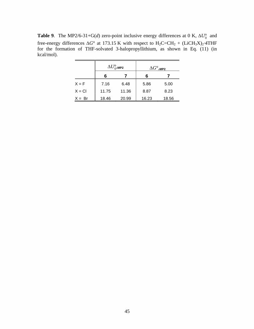
45
Table 9. The MP2/6-31+G(d) zero-point inclusive energy differences at 0 K, U°0 and
free-energy differences G° at 173.15 K with respect to H2C=CH2 + (LiCH3X)2·4THF for the formation of THF-solvated 3-halopropyllithium, as shown in Eq. (11) (in kcal/mol).
U°0,MP2 G°,MP2
6 7 6 7
X = F 7.16 6.48 5.86 5.00
X = Cl 11.75 11.36 8.87 8.23
X = Br 18.46 20.99 16.23 18.56
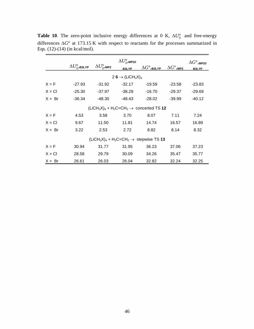
46
Table 10. The zero-point inclusive energy differences at 0 K, U°0 and free-energy
differences G° at 173.15 K with respect to reactants for the processes summarized in Eqs. (12)-(14) (in kcal/mol).
U°0,B3LYP U°0,MP2U°0,MP2//
B3LYP G°,B3LYP G°,MP2G°,MP2//
B3LYP
2 6 (LiCH3X)4
X = F -27.93 -31.92 -32.17 -19.59 -23.58 -23.83
X = Cl -25.30 -37.97 -38.29 -16.70 -29.37 -29.69
X = Br -36.34 -48.30 -48.43 -28.02 -39.99 -40.12
(LiCH3X)4 + H2C=CH2 concerted TS 12
X = F 4.53 3.58 3.70 8.07 7.11 7.24
X = Cl 9.67 11.50 11.81 14.74 16.57 16.89
X = Br 3.22 2.53 2.72 8.82 8.14 8.32
(LiCH3X)4 + H2C=CH2 stepwise TS 13
X = F 30.94 31.77 31.95 36.23 37.06 37.23
X = Cl 28.58 29.79 30.09 34.26 35.47 35.77
X = Br 26.61 26.03 26.04 32.82 32.24 32.25
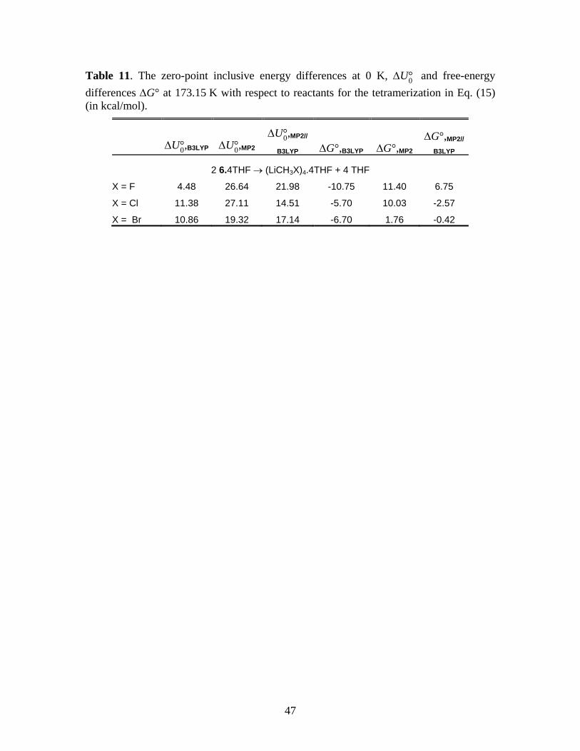
47
Table 11. The zero-point inclusive energy differences at 0 K, U°0 and free-energy
differences G° at 173.15 K with respect to reactants for the tetramerization in Eq. (15) (in kcal/mol).
U°0,B3LYP U°0,MP2U°0,MP2//
B3LYP G°,B3LYP G°,MP2G°,MP2//
B3LYP
2 6.4THF (LiCH3X)4.4THF + 4 THF
X = F 4.48 26.64 21.98 -10.75 11.40 6.75
X = Cl 11.38 27.11 14.51 -5.70 10.03 -2.57
X = Br 10.86 19.32 17.14 -6.70 1.76 -0.42
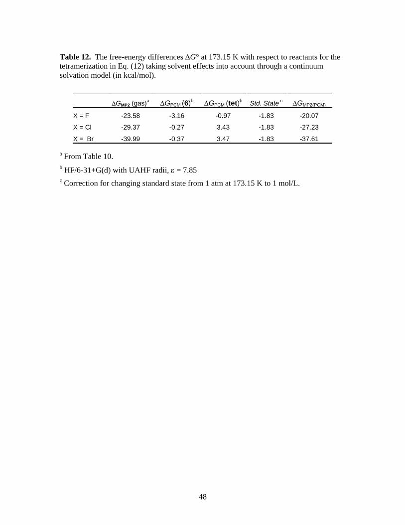
48
Table 12. The free-energy differences G° at 173.15 K with respect to reactants for the tetramerization in Eq. (12) taking solvent effects into account through a continuum solvation model (in kcal/mol).
GMP2 (gas)a GPCM (6)b GPCM (tet)b Std. State c GMP2(PCM)
X = F -23.58 -3.16 -0.97 -1.83 -20.07
X = Cl -29.37 -0.27 3.43 -1.83 -27.23
X = Br -39.99 -0.37 3.47 -1.83 -37.61
a From Table 10. b HF/6-31+G(d) with UAHF radii, = 7.85 c Correction for changing standard state from 1 atm at 173.15 K to 1 mol/L.
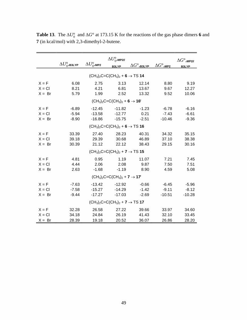
49
Table 13. The U°0 and G° at 173.15 K for the reactions of the gas phase dimers 6 and
7 (in kcal/mol) with 2,3-dimethyl-2-butene.
U°0,B3LYP U°0,MP2U°0,MP2//
B3LYP G°,B3LYP G°,MP2G°,MP2//
B3LYP
(CH3)2C=C(CH3)2 + 6 TS 14
X = F 6.08 2.75 3.13 12.14 8.80 9.19 X = Cl 8.21 4.21 6.81 13.67 9.67 12.27 X = Br 5.79 1.99 2.52 13.32 9.52 10.06
(CH3)2C=C(CH3)2 + 6 16
X = F -6.89 -12.45 -11.82 -1.23 -6.78 -6.16 X = Cl -5.94 -13.58 -12.77 0.21 -7.43 -6.61 X = Br -8.90 -16.86 -15.75 -2.51 -10.46 -9.36
(CH3)2C=C(CH3)2 + 6 TS 16
X = F 33.39 27.40 28.23 40.31 34.32 35.15 X = Cl 39.18 29.39 30.68 46.89 37.10 38.38 X = Br 30.39 21.12 22.12 38.43 29.15 30.16
(CH3)2C=C(CH3)2 + 7 TS 15
X = F 4.81 0.95 1.19 11.07 7.21 7.45 X = Cl 4.44 2.06 2.08 9.87 7.50 7.51 X = Br 2.63 -1.68 -1.19 8.90 4.59 5.08
(CH3)2C=C(CH3)2 + 7 17
X = F -7.63 -13.42 -12.92 -0.66 -6.45 -5.96 X = Cl -7.58 -15.27 -14.29 -1.42 -9.11 -8.12 X = Br -9.44 -17.27 -17.03 -2.69 -10.51 -10.28
(CH3)2C=C(CH3)2 + 7 TS 17
X = F 32.28 26.58 27.22 39.66 33.97 34.60 X = Cl 34.18 24.84 26.19 41.43 32.10 33.45 X = Br 28.39 19.18 20.52 36.07 26.86 28.20
50
Figure Captions
1. The MP2/6-31+G(d) intrinsic reaction coordinate (IRC) in (amu)1/2 bohr for the concerted reaction and the first step of the stepwise mechanism for the gas phase monomer LiCH2Br. All energies are relative to the asymptotic reactants. The point B is at an energy of –27.9 kcal/mol, at reaction coordinate value of 2.99. Solid lines with symbols are based on IRC calculations while the dashed lines are “physically reasonable” interpolations through available data. The zero of the energy axis represents the reactants at infinite separation.
2. The structures corresponding to the labeled points on the IRC’s shown in Figure 1 for LiCH2X, X = Br. The corresponding structures for X = F and Cl are similar.
3. The B3LYP/6-31+G(d) IRC’s in (amu)1/2 bohr for the anti (solid symbols) and syn (open symbols) elimination of LiCl from the intermediate Li-(CH2)3-Cl. All energies are relative to asymptotic reactants H2C=CH2 + LiCH2Cl. Point I is at Erel = –31.6 kcal/mol at reaction coordinate value of 3.96.
4. The structures corresponding to the labeled points on the B3LYP/6-31+G(d) IRC’s shown in Figure 3 for LiCH2Cl. The corresponding structures for X = F and Cl are similar. Bond lengths shown are in Angstroms.
5. The MP2/6-31+G(d) IRC in (amu)1/2 bohr for the concerted and stepwise reactions of gas phase dimers of LiCH2Br. All energies are relative to the asymptotic reactants H2C=CH2 + LiCH2Br. (a) IRC’s of dimer 6. The point B is at an energy of –13.8 kcal/mol, at reaction coordinate value of 2.97. (b) IRC’s of dimer 7. The point B is at an energy of –15.2 kcal/mol, at reaction coordinate value of 2.69. The significance of the dashed lines are the same as in Figure 1. The zero of the energy axis represents the reactants at infinite separation.
6. The structures corresponding to the labeled points on the IRC’s of dimer 6 shown in Figure 5(a) for LiCH2X, X = Br. The corresponding structures for X = F and Cl are similar. Bond lengths shown are in Angstroms.
7. The structures corresponding to the labeled points on the IRC’s of dimer 7 shown in Figure 5(b), for LiCH2X, X = Br. Structures for X = F and Cl are similar. Bond lengths shown are in Angstroms.
8. Equilibrium structures of 6•4THF for X = F obtained from (a) B3LYP/6-31+G(d) starting with the HF/6-31+G(d) equilibrium structure, (b) MP2/6-31+G(d) starting with the structure in panel (a), and (c) the B3LYP/6-31+G(d) structure obtained from the structure in panel (b). Hydrogens are not shown for clarity.
9. MP2 free energy profiles of the reactions of the (a) THF-solvated monomer and (b) dimer 6 with ethylene. The energy levels are color-coded based on X: blue (F), green (Cl), and red (Br). The lines connect the average energy of the three derivatives of each species. All energies are relative to the reactants. For clarity, the products LiX + cyclopropane, which are at very large negative values, are not shown.
10. The MP2/6-31+G(d) structures of the tetramer, the transition state for the concerted (TS 12) and stepwise (TS 13) reactions for the case X = F.
11. Upper panels: The MP2/6-31+G(d) transition states for the concerted reactions of dimer 6 (TS 14) and dimer 7 (TS 15) with 2,3-dimethylbutene for the case X = Br. Lower panels: The
51
MP2/6-31+G(d) structures of the pre-reactive complex 16 and TS 16 for dimer 6, and the pre-reactive complex 17 and TS 17 for dimer 7 for the stepwise reactions with 2,3-dimethylbutene for the case X = Br. Hydrogens are not shown for clarity.
12. MP2/6-31+G(d) structures of TS 14 (top row) and TS 15 (bottom row) showing Merz-Singh-Kollman charges and Li-C distances in Angstroms. Left: LiCH2F; Center: LiCH2Cl; Right: LiCH2Br. The stronger interaction in TS 15 for X = Br leads to a weakly bound pre-reactive complex in the intrinsic reaction coordinate and a negative reaction barrier relative to reactants.
13. MP2/6-31+G(d) IRC’s in (amu)1/2 bohr for dimers 6 and 7 for X = Cl and Br reacting with dimethylbutene. The symbols connected by solid lines indicate the extent to which IRC calculations could be converged. The dashed lines are “physically reasonable” spline interpolations reach zero energy at –10. The zero of the energy axis represents the reactants at infinite separation.
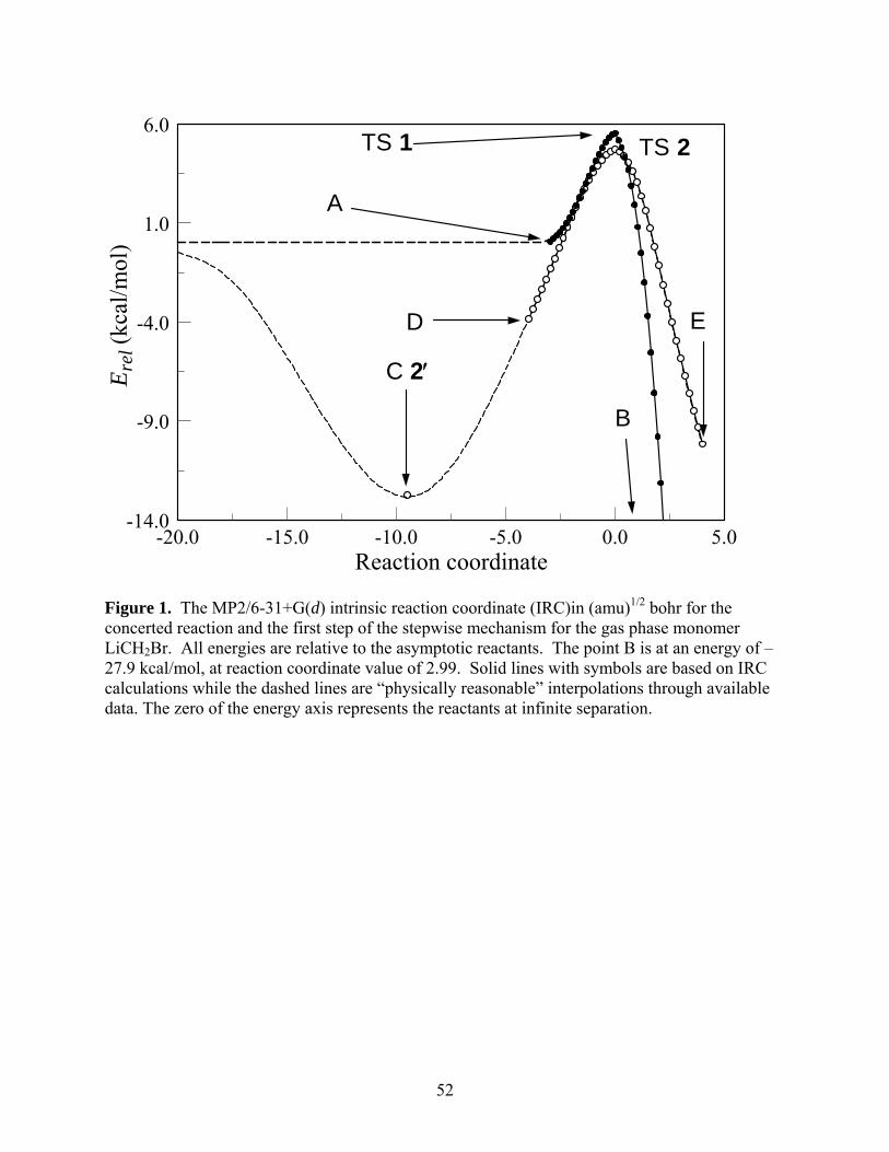
52
Reaction coordinate-20.0 -15.0 -10.0 -5.0 0.0 5.0
Ere
l (kc
al/m
ol)
-14.0
-9.0
-4.0
1.0
6.0
A
D
C 2
B
E
TS 1 TS 2
Figure 1. The MP2/6-31+G(d) intrinsic reaction coordinate (IRC)in (amu)1/2 bohr for the concerted reaction and the first step of the stepwise mechanism for the gas phase monomer LiCH2Br. All energies are relative to the asymptotic reactants. The point B is at an energy of –27.9 kcal/mol, at reaction coordinate value of 2.99. Solid lines with symbols are based on IRC calculations while the dashed lines are “physically reasonable” interpolations through available data. The zero of the energy axis represents the reactants at infinite separation.
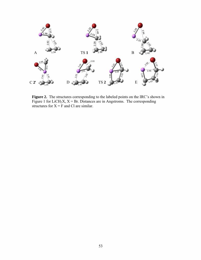
53
Figure 2. The structures corresponding to the labeled points on the IRC’s shown in Figure 1 for LiCH2X, X = Br. Distances are in Angstroms. The corresponding structures for X = F and Cl are similar.
PSI-Plot Working Demo
www.polysoftware.com
PSI-Plot Working Demo
www.polysoftware.com
PSI-Plot Working Demo
www.polysoftware.com
PSI-Plot Working Demo
www.polysoftware.com
PSI-Plot Working Demo
www.polysoftware.com
PSI-Plot Working
www.polysoftware
PSI-Plot Working Demo
www.polysoftware.com
PSI-Plot Working
www.polysoftware2.
82 3.02
1.98
2.40
1.34
2.10
A
PSI-Plot Working Demo
www.polysoftware.com
PSI-Plot Working Demo
www.polysoftware.com
PSI-Plot Working Demo
www.polysoftware.com
PSI-Plot Working Demo
www.polysoftware.com
PSI-Plot Working Demo
www.polysoftware.com
PSI-Plot Working D
www.polysoftware
PSI-Plot Working Demo
www.polysoftware.com
PSI-Plot Working D
www.polysoftware
1.68
2.02
2.24
2.28
1.42
2.94
B
PSI-Plot Working Demo
www.polysoftware.com
PSI-Plot Working Demo
www.polysoftware.com
PSI-Plot Working Demo
www.polysoftware.com
PSI-Plot Working Demo
www.polysoftware.com
PSI-Plot Working Demo
www.polysoftware.com
PSI-Plot Work
www.polysoftw
PSI-Plot Working Demo
www.polysoftware.com
PSI-Plot Work
www.polysoftw
2.23 2.66
1.35
2.01
2.03
2.40
PSI-Plot Working Demo
www.polysoftware.com
PSI-Plot Working Demo
www.polysoftware.com
PSI-Plot Working Demo
www.polysoftware.com
PSI-Plot Working Demo
www.polysoftware.com
PSI-Plot Working Demo
www.polysoftware.com
PSI-Plot Worki
www.polysoftw
PSI-Plot Working Demo
www.polysoftware.com
PSI-Plot Worki
www.polysoftw
2.50
2.00
1.53
1.57
2.12
2.45
PSI-Plot Working Demo
www.polysoftware.com
PSI-Plot Working Demo
www.polysoftware.com
PSI-Plot Working Demo
www.polysoftware.com
PSI-Plot Working Demo
www.polysoftware.com
PSI-Plot Working Demo
www.polysoftware.com
PSI-Plot Working
www.polysoftwar
PSI-Plot Working Demo
www.polysoftware.com
PSI-Plot Working
www.polysoftwar
2.28
2.53
1.36
2.03
2.32 2.49
TS 1
PSI-Plot Working Demo
www.polysoftware.com
PSI-Plot Working Demo
www.polysoftware.com
PSI-Plot Working Demo
www.polysoftware.com
PSI-Plot Working Demo
www.polysoftware.com
PSI-Plot Working Demo
www.polysoftware.com
PSI-Plot Work
www.polysoft
PSI-Plot Working Demo
www.polysoftware.com
PSI-Plot Work
www.polysoft
1.41
2.03
2.06
2.09
2.43
2.04
TS 2
PSI-Plot Working Demo
www.polysoftware.com
PSI-Plot Working Demo
www.polysoftware.com
PSI-Plot Working Demo
www.polysoftware.com
PSI-Plot Working Demo
www.polysoftware.com
PSI-Plot Working Demo
www.polysoftware.com
PSI-Plot Workin
www.polysoftwa
PSI-Plot Working Demo
www.polysoftware.com
PSI-Plot Workin
www.polysoftwa
2.43
2.41
1.35
2.45
2.00
2.08
C 2 ED
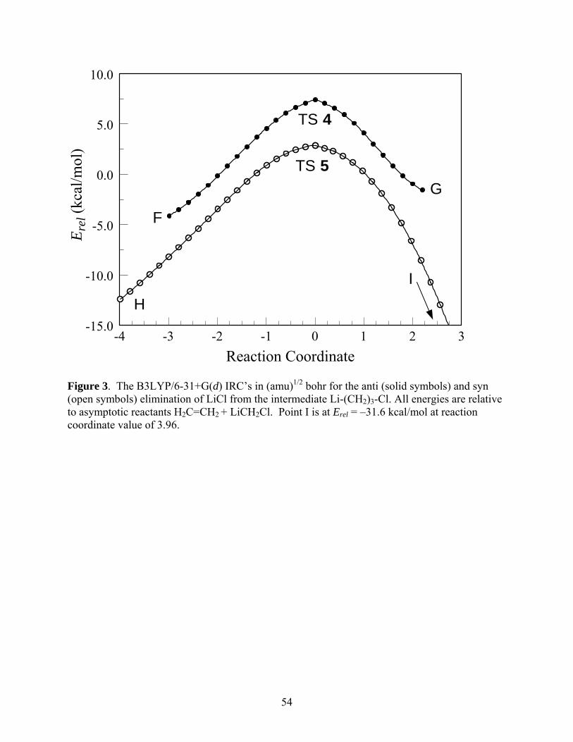
54
Reaction Coordinate-4 -3 -2 -1 0 1 2 3
Ere
l (kc
al/m
ol)
-15.0
-10.0
-5.0
0.0
5.0
10.0
H
TS 5
I
F
TS 4
G
Figure 3. The B3LYP/6-31+G(d) IRC’s in (amu)1/2 bohr for the anti (solid symbols) and syn (open symbols) elimination of LiCl from the intermediate Li-(CH2)3-Cl. All energies are relative to asymptotic reactants H2C=CH2 + LiCH2Cl. Point I is at Erel = –31.6 kcal/mol at reaction coordinate value of 3.96.
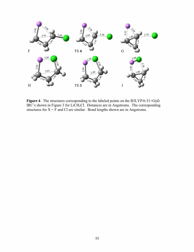
55
Figure 4. The structures corresponding to the labeled points on the B3LYP/6-31+G(d) IRC’s shown in Figure 3 for LiCH2Cl. Distances are in Angstroms. The corresponding structures for X = F and Cl are similar. Bond lengths shown are in Angstroms.
PSI-Plot Working Demo
www.polysoftware.com
PSI-Plot Working Demo
www.polysoftware.com
PSI-Plot Working Demo
www.polysoftware.com
PSI-Plot Working Demo
www.polysoftware.com
PSI-Plot Working Demo
www.polysoftware.com
PSI-Plot Working D
www.polysoftware
PSI-Plot Working Demo
www.polysoftware.com
PSI-Plot Working D
www.polysoftware
2.05
1.55 1.54
1.93
2.56
2.41
F
PSI-Plot Working Demo
www.polysoftware.com
PSI-Plot Working Demo
www.polysoftware.com
PSI-Plot Working Demo
www.polysoftware.com
PSI-Plot Working Demo
www.polysoftware.com
PSI-Plot Working Demo
www.polysoftware.com
PSI-Plot Working D
www.polysoftware
PSI-Plot Working Demo
www.polysoftware.com
PSI-Plot Working D
www.polysoftware
2.09
1.53
1.47
2.28
2.352.04
TS 4
PSI-Plot Working Demo
www.polysoftware.com
PSI-Plot Working Demo
www.polysoftware.com
PSI-Plot Working Demo
www.polysoftware.com
PSI-Plot Working Demo
www.polysoftware.com
PSI-Plot Working Demo
www.polysoftware.com
PSI-Plot Working D
www.polysoftware
PSI-Plot Working Demo
www.polysoftware.com
PSI-Plot Working D
www.polysoftware
2.12
2.03
1.602.75
1.52
1.47
G
PSI-Plot Working Demo
www.polysoftware.com
PSI-Plot Working Demo
www.polysoftware.com
PSI-Plot Working Demo
www.polysoftware.com
PSI-Plot Working Demo
www.polysoftware.com
PSI-Plot Working Demo
www.polysoftware.com
PSI-Plot Working D
www.polysoftware
PSI-Plot Working Demo
www.polysoftware.com
PSI-Plot Working D
www.polysoftware
2.30
2.01
2.61
2.05
1.54 1.53
H
PSI-Plot Working Demo
www.polysoftware.com
PSI-Plot Working Demo
www.polysoftware.com
PSI-Plot Working Demo
www.polysoftware.com
PSI-Plot Working Demo
www.polysoftware.com
PSI-Plot Working Demo
www.polysoftware.com
PSI-Plot Working D
www.polysoftware
PSI-Plot Working Demo
www.polysoftware.com
PSI-Plot Working D
www.polysoftware
2.18
2.0
4
2.49
2.39
1.54
1.48
TS 5
PSI-Plot Working Demo
www.polysoftware.com
PSI-Plot Working Demo
www.polysoftware.com
PSI-Plot Working Demo
www.polysoftware.com
PSI-Plot Working Demo
www.polysoftware.com
PSI-Plot Working Demo
www.polysoftware.com
PSI-Plot Working D
www.polysoftware
PSI-Plot Working Demo
www.polysoftware.com
PSI-Plot Working D
www.polysoftware
2.08
2.08
2.78
1.85
1.50 1.45
I
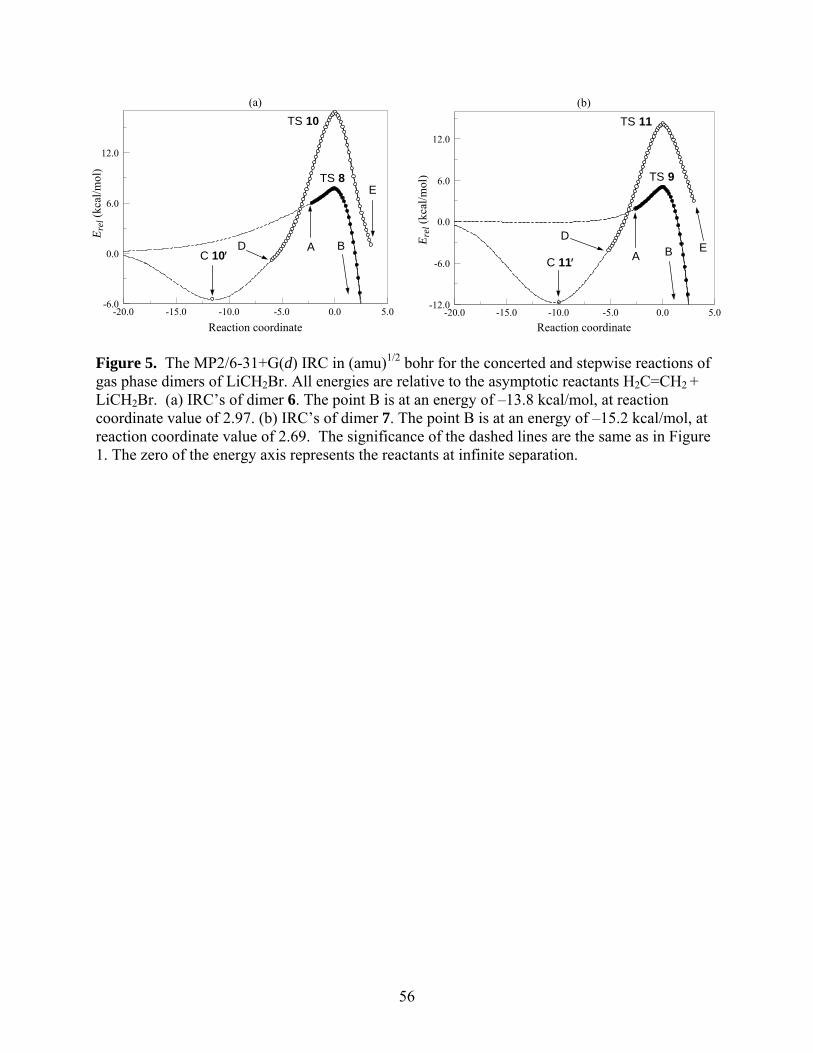
56
Reaction coordinate-20.0 -15.0 -10.0 -5.0 0.0 5.0
Ere
l (kc
al/m
ol)
-6.0
0.0
6.0
12.0
(a)
ADC 10
TS 8
TS 10
B
E
Reaction coordinate-20.0 -15.0 -10.0 -5.0 0.0 5.0
Ere
l (kc
al/m
ol)
-12.0
-6.0
0.0
6.0
12.0
(b)
A
D
C 11
TS 9
TS 11
B E
Figure 5. The MP2/6-31+G(d) IRC in (amu)1/2 bohr for the concerted and stepwise reactions of gas phase dimers of LiCH2Br. All energies are relative to the asymptotic reactants H2C=CH2 + LiCH2Br. (a) IRC’s of dimer 6. The point B is at an energy of –13.8 kcal/mol, at reaction coordinate value of 2.97. (b) IRC’s of dimer 7. The point B is at an energy of –15.2 kcal/mol, at reaction coordinate value of 2.69. The significance of the dashed lines are the same as in Figure 1. The zero of the energy axis represents the reactants at infinite separation.
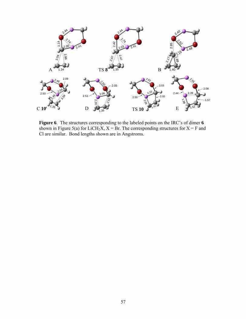
57
Figure 6. The structures corresponding to the labeled points on the IRC’s of dimer 6 shown in Figure 5(a) for LiCH2X, X = Br. The corresponding structures for X = F and Cl are similar. Bond lengths shown are in Angstroms.
PSI-Plot Working Demo
www.polysoftware.com
PSI-Plot Working Demo
www.polysoftware.com
PSI-Plot Working Demo
www.polysoftware.com
PSI-Plot Working Demo
www.polysoftware.com
PSI-Plot Working Demo
www.polysoftware.com
PSI-Plot Workin
www.polysoftwa
PSI-Plot Working Demo
www.polysoftware.com
PSI-Plot Workin
www.polysoftwa
3.04
2.86
2.002.1
4
1.34
2.74
2.41
2.44
A
PSI-Plot Working Demo
www.polysoftware.com
PSI-Plot Working Demo
www.polysoftware.com
PSI-Plot Working Demo
www.polysoftware.com
PSI-Plot Working Demo
www.polysoftware.com
PSI-Plot Working Demo
www.polysoftware.com
PSI-Plot Workin
www.polysoftw
PSI-Plot Working Demo
www.polysoftware.com
PSI-Plot Workin
www.polysoftw
1.35
2.67
2.47
2.032.4
2
2.44
2.74
2.41
TS 8
PSI-Plot Working Demo
www.polysoftware.com
PSI-Plot Working Demo
www.polysoftware.com
PSI-Plot Working Demo
www.polysoftware.com
PSI-Plot Working Demo
www.polysoftware.com
PSI-Plot Working Demo
www.polysoftware.com
PSI-Plot Workin
www.polysoftw
PSI-Plot Working Demo
www.polysoftware.com
PSI-Plot Workin
www.polysoftw2.17
1.401.88
2.19
2.85
2.52
2.48
2.40
B
PSI-Plot Working Demo
www.polysoftware.com
PSI-Plot Working Demo
www.polysoftware.com
PSI-Plot Working Demo
www.polysoftware.com
PSI-Plot Working Demo
www.polysoftware.com
PSI-Plot Working Demo
www.polysoftware.com
PSI-Plot Workin
www.polysoftw
PSI-Plot Working Demo
www.polysoftware.com
PSI-Plot Workin
www.polysoftw
2.46
3.59
1.35
2.04
2.092.46
2.50
C 10
PSI-Plot Working Demo
www.polysoftware.com
PSI-Plot Working Demo
www.polysoftware.com
PSI-Plot Working Demo
www.polysoftware.com
PSI-Plot Working Demo
www.polysoftware.com
PSI-Plot Working Demo
www.polysoftware.com
PSI-Plot Working
www.polysoftwa
PSI-Plot Working Demo
www.polysoftware.com
PSI-Plot Working
www.polysoftwa
2.20
1.352.
52
2.06
2.05
2.50
2.51
D
PSI-Plot Working Demo
www.polysoftware.com
PSI-Plot Working Demo
www.polysoftware.com
PSI-Plot Working Demo
www.polysoftware.com
PSI-Plot Working Demo
www.polysoftware.com
PSI-Plot Working Demo
www.polysoftware.com
PSI-Plot Workin
www.polysoftw
PSI-Plot Working Demo
www.polysoftware.com
PSI-Plot Workin
www.polysoftw1.41
2.05
2.002.15
2.50
2.03
2.52
TS 10
PSI-Plot Working Demo
www.polysoftware.com
PSI-Plot Working Demo
www.polysoftware.com
PSI-Plot Working Demo
www.polysoftware.com
PSI-Plot Working Demo
www.polysoftware.com
PSI-Plot Working Demo
www.polysoftware.com
PSI-Plot Working
www.polysoftwa
PSI-Plot Working Demo
www.polysoftware.com
PSI-Plot Working
www.polysoftwa
1.52
1.57
2.39
1.98
2.08
2.44
2.55
E
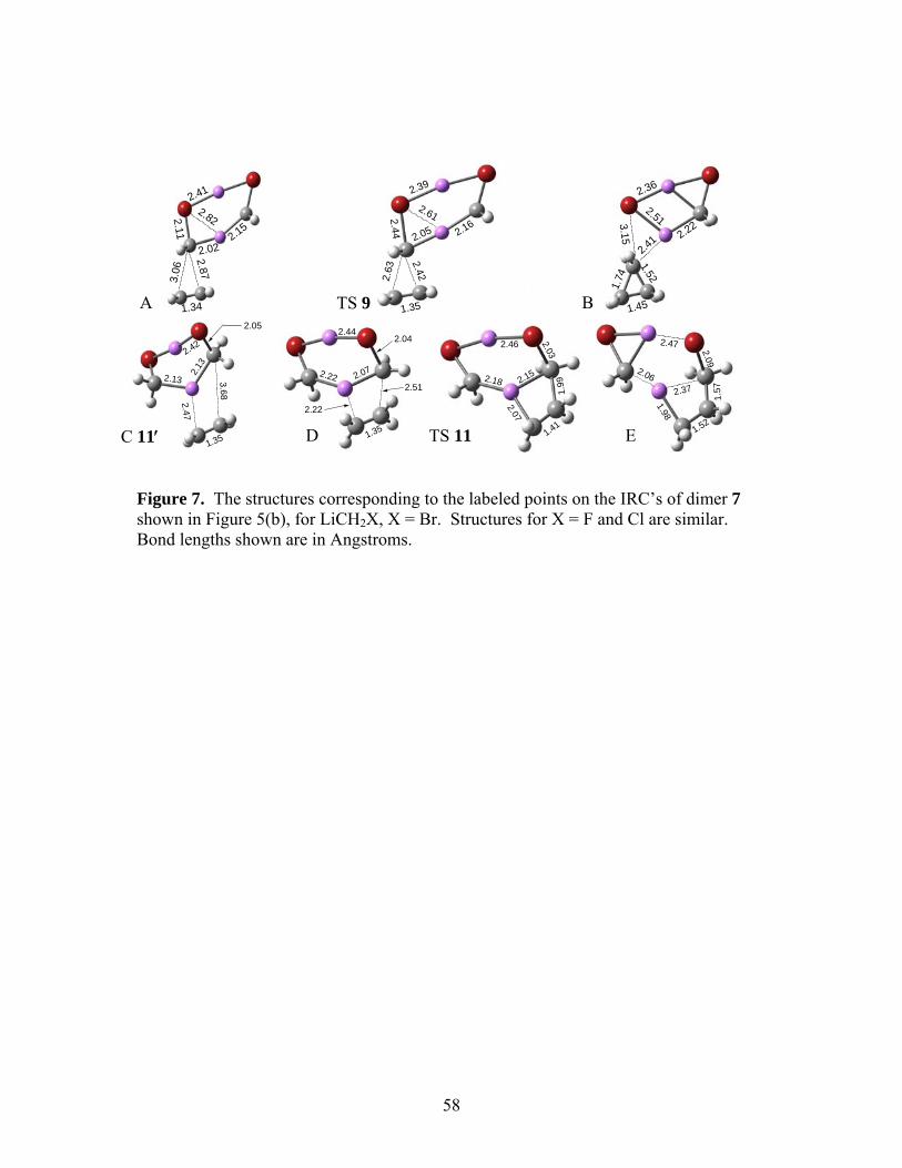
58
PSI-Plot Working Demo
www.polysoftware.com
PSI-Plot Working Demo
www.polysoftware.com
PSI-Plot Working Demo
www.polysoftware.com
PSI-Plot Working Demo
www.polysoftware.com
PSI-Plot Working Demo
www.polysoftware.com
PSI-Plot Working D
www.polysoftware
PSI-Plot Working Demo
www.polysoftware.com
PSI-Plot Working D
www.polysoftware1.41
2.07
1.992.152.18
2.032.46
Figure 7. The structures corresponding to the labeled points on the IRC’s of dimer 7 shown in Figure 5(b), for LiCH2X, X = Br. Structures for X = F and Cl are similar. Bond lengths shown are in Angstroms.
PSI-Plot Working Demo
www.polysoftware.com
PSI-Plot Working Demo
www.polysoftware.com
PSI-Plot Working Demo
www.polysoftware.com
PSI-Plot Working Demo
www.polysoftware.com
PSI-Plot Working Demo
www.polysoftware.com
PSI-Plot Working D
www.polysoftware
PSI-Plot Working Demo
www.polysoftware.com
PSI-Plot Working D
www.polysoftware
3.06
2.87
1.34
2.02
2.11
2.41
2.15
2.82
PSI-Plot Working Demo
www.polysoftware.com
PSI-Plot Working Demo
www.polysoftware.com
PSI-Plot Working Demo
www.polysoftware.com
PSI-Plot Working Demo
www.polysoftware.com
PSI-Plot Working Demo
www.polysoftware.com
PSI-Plot Working D
www.polysoftware.
PSI-Plot Working Demo
www.polysoftware.com
PSI-Plot Working D
www.polysoftware.
2.63
2.42
1.35
2.05
2.44 2.16
2.39
2.61
PSI-Plot Working Demo
www.polysoftware.com
PSI-Plot Working Demo
www.polysoftware.com
PSI-Plot Working Demo
www.polysoftware.com
PSI-Plot Working Demo
www.polysoftware.com
PSI-Plot Working Demo
www.polysoftware.com
PSI-Plot Working D
www.polysoftware
PSI-Plot Working Demo
www.polysoftware.com
PSI-Plot Working D
www.polysoftware1.74
1.52
1.45
3.15
2.41
2.51
2.36
2.22
PSI-Plot Working Demo
www.polysoftware.com
PSI-Plot Working Demo
www.polysoftware.com
PSI-Plot Working Demo
www.polysoftware.com
PSI-Plot Working Demo
www.polysoftware.com
PSI-Plot Working Demo
www.polysoftware.com
PSI-Plot Working D
www.polysoftware
PSI-Plot Working Demo
www.polysoftware.com
PSI-Plot Working D
www.polysoftware1.35
2.22
2.512.072.22
2.042.44
PSI-Plot Working Demo
www.polysoftware.com
PSI-Plot Working Demo
www.polysoftware.com
PSI-Plot Working Demo
www.polysoftware.com
PSI-Plot Working Demo
www.polysoftware.com
PSI-Plot Working Demo
www.polysoftware.com
PSI-Plot Working D
www.polysoftware
PSI-Plot Working Demo
www.polysoftware.com
PSI-Plot Working D
www.polysoftware1.52
1.98
1.57
2.09
2.37
2.06
2.47PSI-Plot Working Demo
www.polysoftware.com
PSI-Plot Working Demo
www.polysoftware.com
PSI-Plot Working Demo
www.polysoftware.com
PSI-Plot Working Demo
www.polysoftware.com
PSI-Plot Working Demo
www.polysoftware.com
PSI-Plot Working D
www.polysoftware
PSI-Plot Working Demo
www.polysoftware.com
PSI-Plot Working D
www.polysoftware
2.47
3.68
2.13
2.13
1.35
2.05
2.42
A TS 9 B
C 11 D TS 11 E
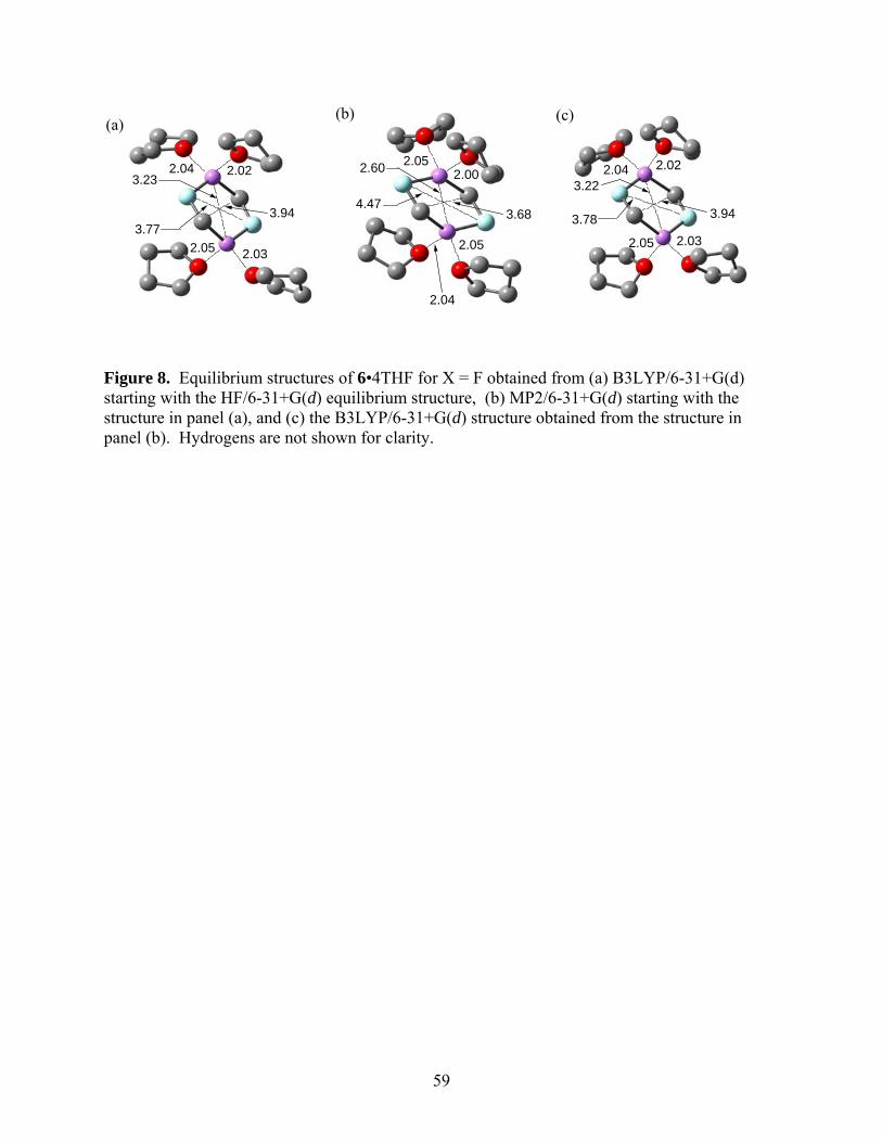
59
(a)
2.04 2.02
2.05 2.03
3.23
3.773.94
(b)
2.052.00
2.04
2.05
2.60
3.684.47
(c)
2.04 2.02
2.05 2.03
3.78
3.22
3.94
Figure 8. Equilibrium structures of 6•4THF for X = F obtained from (a) B3LYP/6-31+G(d) starting with the HF/6-31+G(d) equilibrium structure, (b) MP2/6-31+G(d) starting with the structure in panel (a), and (c) the B3LYP/6-31+G(d) structure obtained from the structure in panel (b). Hydrogens are not shown for clarity.
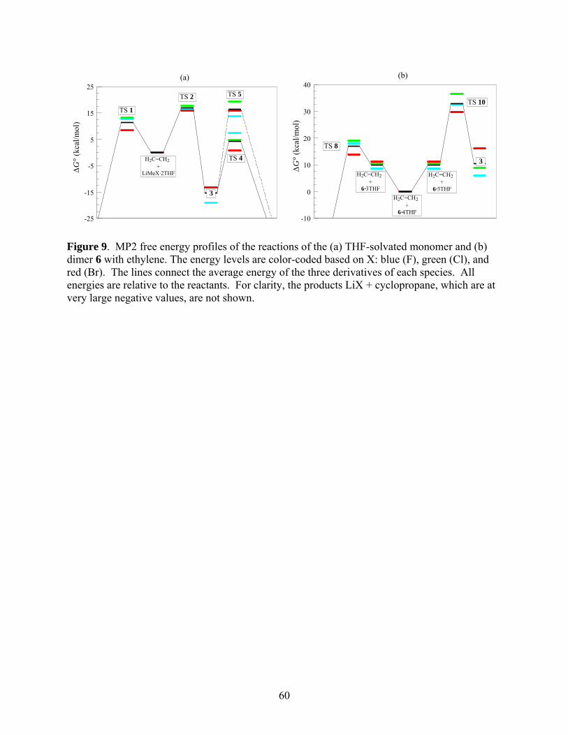
60
G
° (k
cal/
mol
)
-25
-15
-5
5
15
25(a)
H2C=CH2 + LiMeX·2THF
TS 1
TS 2
3
TS 5
TS 4
G
° (k
cal/m
ol)
-10
0
10
20
30
40(b)
H2C=CH2 + 6·4THF
TS 8
3
TS 10
H2C=CH2 + 6·3THF
H2C=CH2 + 6·3THF
Figure 9. MP2 free energy profiles of the reactions of the (a) THF-solvated monomer and (b) dimer 6 with ethylene. The energy levels are color-coded based on X: blue (F), green (Cl), and red (Br). The lines connect the average energy of the three derivatives of each species. All energies are relative to the reactants. For clarity, the products LiX + cyclopropane, which are at very large negative values, are not shown.
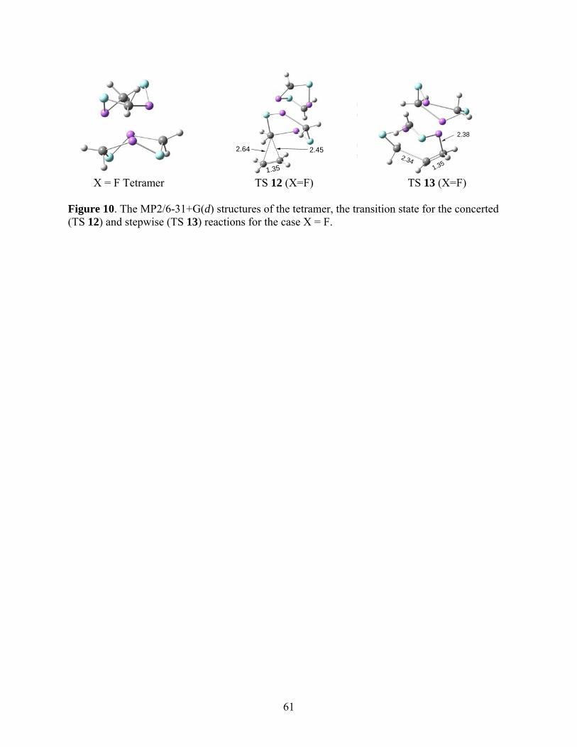
61
PSI-Plot Working Demo
www.polysoftware.com
PSI-Plot Working Demo
www.polysoftware.com
PSI-Plot Working Demo
www.polysoftware.com
PSI-Plot Working Demo
www.polysoftware.com
PSI-Plot Working Demo
www.polysoftware.com
PSI-Plot Working D
www.polysoftware
PSI-Plot Working Demo
www.polysoftware.com
PSI-Plot Working D
www.polysoftware2.64 2.45
1.35
PSI-Plot Working Demo
www.polysoftware.com
PSI-Plot Working Demo
www.polysoftware.com
PSI-Plot Working Demo
www.polysoftware.com
PSI-Plot Working Demo
www.polysoftware.com
PSI-Plot Working Demo
www.polysoftware.com
PSI-Plot Working D
www.polysoftware
PSI-Plot Working Demo
www.polysoftware.com
PSI-Plot Working D
www.polysoftware2.341.35
2.38
X = F Tetramer TS 12 (X=F) TS 13 (X=F) Figure 10. The MP2/6-31+G(d) structures of the tetramer, the transition state for the concerted (TS 12) and stepwise (TS 13) reactions for the case X = F.
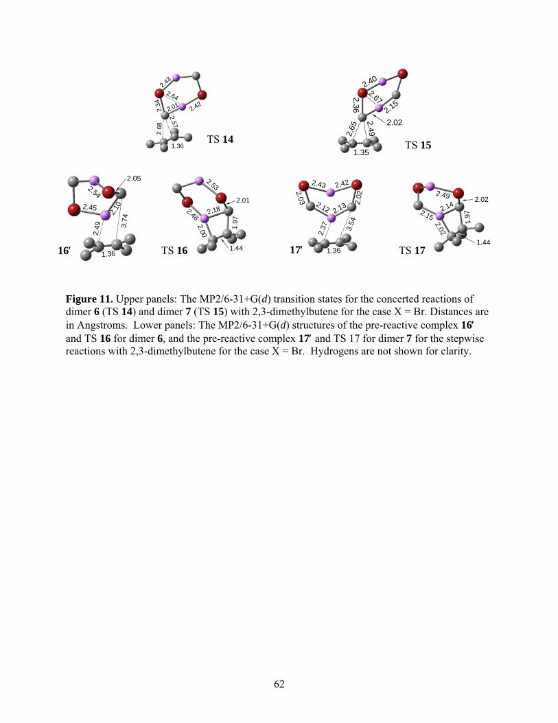
62
Figure 11. Upper panels: The MP2/6-31+G(d) transition states for the concerted reactions of dimer 6 (TS 14) and dimer 7 (TS 15) with 2,3-dimethylbutene for the case X = Br. Distances are in Angstroms. Lower panels: The MP2/6-31+G(d) structures of the pre-reactive complex 16 and TS 16 for dimer 6, and the pre-reactive complex 17 and TS 17 for dimer 7 for the stepwise reactions with 2,3-dimethylbutene for the case X = Br. Hydrogens are not shown for clarity.
2.68
2.57
1.36
2.012.34
2.42
2.43
2.64
1.35
2.65
2.49
2.02
2.36
2.40
2.15
2.67
TS 14 TS 15
1.36
2.49 3.
74
2.45
2.10
2.052.54
1.44
2.00
1.97
2.182.01
2.48
2.53
1.36
2.37 3.
54
2.13 2.02
2.12
2.422.43
2.03
1.44
2.02
1.97
2.142.02
2.49
2.15
TS 16 TS 17 16 17
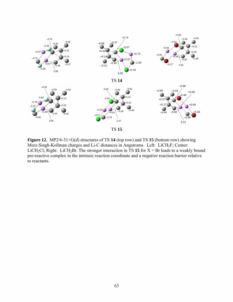
63
3.88
+0.18
+0.14
+0.67
+0.67
–0.45–0.48
–0.46 –0.47
–0.75
–0.39
–0.30
–0.75
3.30
+0.20
+0.14+0.57
+0.72
–1.00
–0.18
–0.57
–0.74
–0.37–0.56
–0.41–0.30
–0.52 –0.48+0.48
–0.50
+0.22
+0.18
–0.27
–0.52
+0.65
–0.91
–0.45 –0.55
3.26
TS 14
3.84
+0.13
+0.25
+0.48
+0.76
–0.44 –0.46
–0.53–0.50 –0.50
–0.60
–0.37
–0.55
3.47
+0.12
+0.32
+0.54+0.62
–0.64 –0.46 –0.56
–0.56 –0.45
–0.55
–0.22–0.78
–0.80
–0.60–0.44
+0.66
3.21
+0.55
+0.27
+0.17
–0.59 –0.44
–0.99
–0.49
–0.16
TS 15 Figure 12. MP2/6-31+G(d) structures of TS 14 (top row) and TS 15 (bottom row) showing Merz-Singh-Kollman charges and Li-C distances in Angstroms. Left: LiCH2F; Center: LiCH2Cl; Right: LiCH2Br. The stronger interaction in TS 15 for X = Br leads to a weakly bound pre-reactive complex in the intrinsic reaction coordinate and a negative reaction barrier relative to reactants.
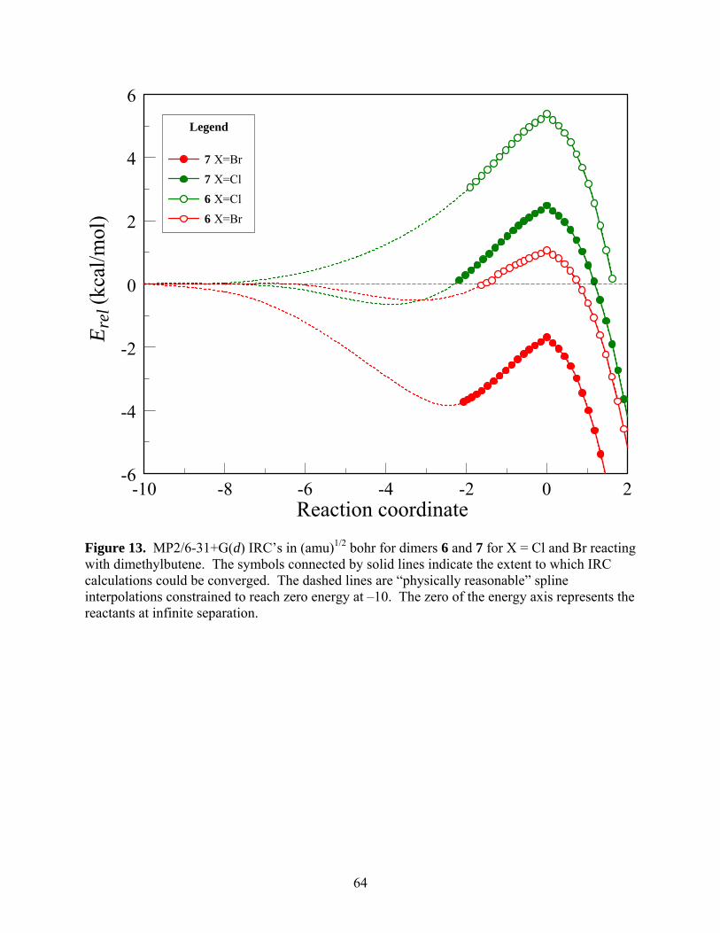
64
Reaction coordinate-10 -8 -6 -4 -2 0 2
Ere
l (kc
al/m
ol)
-6
-4
-2
0
2
4
6
Legend
7 X=Br
7 X=Cl
6 X=Cl
6 X=Br
Figure 13. MP2/6-31+G(d) IRC’s in (amu)1/2 bohr for dimers 6 and 7 for X = Cl and Br reacting with dimethylbutene. The symbols connected by solid lines indicate the extent to which IRC calculations could be converged. The dashed lines are “physically reasonable” spline interpolations constrained to reach zero energy at –10. The zero of the energy axis represents the reactants at infinite separation.
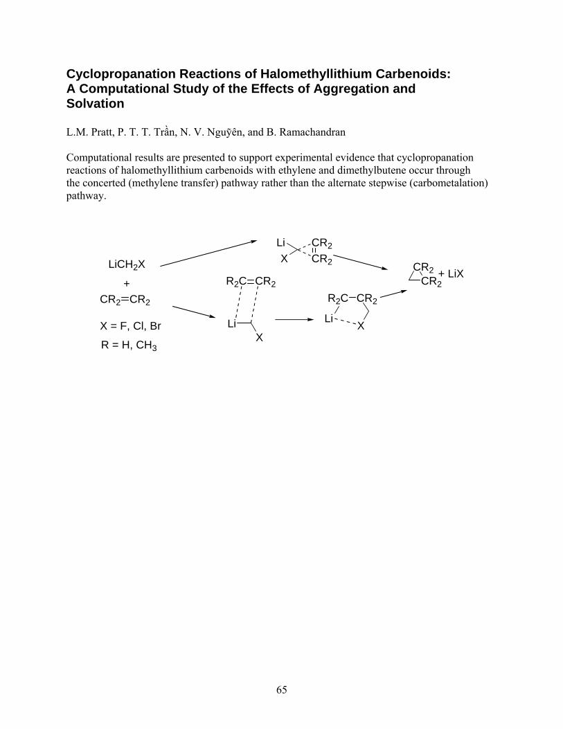
65
Cyclopropanation Reactions of Halomethyllithium Carbenoids: A Computational Study of the Effects of Aggregation and Solvation L.M. Pratt, P. T. T. Trần, N. V. Nguỹên, and B. Ramachandran Computational results are presented to support experimental evidence that cyclopropanation reactions of halomethyllithium carbenoids with ethylene and dimethylbutene occur through the concerted (methylene transfer) pathway rather than the alternate stepwise (carbometalation) pathway.
CR2
CR2X
Li
LiX
R2C CR2
LiCH2X
+CR2 CR2
CR2CR2
+ LiX
R2C CR2
LiXX = F, Cl, Br
R = H, CH3