halogen-free security cables - maryland metricsmdmetric.com/prod/helukabel/g.halogen-free...
TRANSCRIPT

Photo: HELUKABEL�
Halogen-free Security Cables
�G

Halogen-free Security Cables
In all locations, due to damages of large amount ofmaterials and more of importance to protect humanlife and technical equipment against damages causedby fire and also for technical enquiries of insurance,the installation of halogen-free security cables arerequired.
You will find on the next following pages the instruc-tions for installation as well as the test methods andlaying indications of the halogen-free security cables.
The most important advantages:
* No fire propagation at local flame influence
* Functionallity for important systems
* No corrosion and damage by released corrosivegases and vapours
* Protection of human life and valuable materials,especially for high quality machines, EDP-systems etc.
* Prevention of heavy and unexpected subsequentdamages
* Low smoke density helps rescue and fire extin-guishing works
�
G
G

Contents and IndexDescription Type Page
G Halogen-free cables
Halogen-free Installation Cables
Installation cable . . . . . . . . . . . . . . . . . . . . . . . . . . . . . . . . . . . . . . . . . . . . . . . . . . . . . . . . . . . . . . . . . . . . . . . . . . . . . . . . . . J-H(St)H . . . . . . . . . . . . . . . . . . . . . . . . . . . . . . . . . . . . . . . . . . . . . . . . . . G4Installation cable . . . . . . . . . . . . . . . . . . . . . . . . . . . . . . . . . . . . . . . . . . . . . . . . . . . . . . . . . . . . . . . . . . . . . . . . . . . . . . . . . . J-2Y(St)H . . . . . . . . . . . . . . . . . . . . . . . . . . . . . . . . . . . . . . . . . . . . . . . . . G5Fire warning cable. . . . . . . . . . . . . . . . . . . . . . . . . . . . . . . . . . . . . . . . . . . . . . . . . . . . . . . . . . . . . . . . . . . . . . . . . . . . . . . . J-H(St)H . . . . . . . . . . . . . . . . . . . . . . . . . . . . . . . . . . . . . . . . . . . . . . . . . . G6Industry-electronic cable E 90, outer jacket orange. . . . . . . . . . . . . . . . . . . . . . . . . . . . JE-H(St)H . . . . . . . . . . . . . . . . . . . . . . . . . . . . . . . . . . . . . . . . . . . . . . . . G7Industry-electronic cable, bunched cable . . . . . . . . . . . . . . . . . . . . . . . . . . . . . . . . . . . . . . . . . . . . JE-LiHCH. . . . . . . . . . . . . . . . . . . . . . . . . . . . . . . . . . . . . . . . . . . . . . . . . G8Fire warning cable E 90, outer jacket red. . . . . . . . . . . . . . . . . . . . . . . . . . . . . . . . . . . . . . . . . . . . JE-H(St)H . . . . . . . . . . . . . . . . . . . . . . . . . . . . . . . . . . . . . . . . . . . . . . . . G9Fire warning cable E 90, galv. steel wire braiding, outer jacket red . . . JE-H(St)HRH. . . . . . . . . . . . . . . . . . . . . . . . . . . . . . . . . . . . . . . . . G10Power cable, VDE approved, without functional endurance . . . . . . . . . . . . . . . N2XH. . . . . . . . . . . . . . . . . . . . . . . . . . . . . . . . . . . . . . . . . G11–G12Power cable, VDE approved, with concentric conductor,without functional endurance . . . . . . . . . . . . . . . . . . . . . . . . . . . . . . . . . . . . . . . . . . . . . . . . . . . . . . . . . . . . . N2XCH. . . . . . . . . . . . . . . . . . . . . . . . . . . . . . . . . . . . . . . . . . . . . . . . . G13Installation security cable, outer jacket orange. . . . . . . . . . . . . . . . . . . . . . . . . . . . . . . . . . . N2XH-FE 180/E 30. . . . . . . . . . . . . . . . . . . . G14–G15Installation security cable, outer jacket orange, copper screened. . . . . . N2XCH-FE 180/E 30. . . . . . . . . . . . . . . . . . G16–G17Installation security cable, outer jacket orange. . . . . . . . . . . . . . . . . . . . . . . . . . . . . . . . . . . NHXH-FE 180/E 30 . . . . . . . . . . . . . . . . . . . G18–G19Installation security cable, outer jacket orange, copper screened. . . . . . NHXCH-FE 180/E 30 . . . . . . . . . . . . . . . . . . . . . . . . . . . G20Installation security cable, outer jacket orange. . . . . . . . . . . . . . . . . . . . . . . . . . . . . . . . . . . N2XH-FE 180/E 90. . . . . . . . . . . . . . . . . . . . G21–G22Installation security cable, outer jacket orange, copper screened. . . . . . N2XCH-FE 180/E 90. . . . . . . . . . . . . . . . . . G23–G24Installation security cable, outer jacket orange. . . . . . . . . . . . . . . . . . . . . . . . . . . . . . . . . . . NHXH-FE 180/E 90 . . . . . . . . . . . . . . . . . . . G25–G26Installation security cable, outer jacket orange, copper screened. . . . . . NHXCH-FE 180/E 90 . . . . . . . . . . . . . . . . . G27–G28
Halogen-free Control Cables
Flexible, number coded cores. . . . . . . . . . . . . . . . . . . . . . . . . . . . . . . . . . . . . . . . . . . . . . . . . . . . . . . . . . . . . . JZ-500 HMH. . . . . . . . . . . . . . . . . . . . . . . . . . . . . . G29–G30Flexible, copper screened . . . . . . . . . . . . . . . . . . . . . . . . . . . . . . . . . . . . . . . . . . . . . . . . . . . . . . . . . . . . . . . . . . . . JZ-500 HMH-C. . . . . . . . . . . . . . . . . . . . . . . . . . . G31–G32
Single cores, rubber-insulated, VDE approved. . . . . . . . . . . . . . . . . . . . . . . . . . . . . . . . . . . . . H05 Z-K, H07 Z-K . . . . . . . . . . . . . . . . . . . . . . . . . . . . . . . . G33PUR single core, low temperature resistant . . . . . . . . . . . . . . . . . . . . . . . . . . . . . . . . . . . . . . . . PUR-Single core. . . . . . . . . . . . . . . . . . . . . . . . . . . . . . . . . . G34
Halogen-free Data Cables
Implementation cable, cores laid up in pairs . . . . . . . . . . . . . . . . . . . . . . . . . . . . . . . . . . . . . . RD-H(St)H Bd. . . . . . . . . . . . . . . . . . . . . . . . . . . . . . . . . . . . . . . G35
Data cable . . . . . . . . . . . . . . . . . . . . . . . . . . . . . . . . . . . . . . . . . . . . . . . . . . . . . . . . . . . . . . . . . . . . . . . . . . . . . . . . . . . . . . . . . . . . DATAFLAMM. . . . . . . . . . . . . . . . . . . . . . . . . . . . . . . . . . . . . . . . G36Data cable, copper screened . . . . . . . . . . . . . . . . . . . . . . . . . . . . . . . . . . . . . . . . . . . . . . . . . . . . . . . . . . . . . . . DATAFLAMM-C. . . . . . . . . . . . . . . . . . . . . . . . . . . . . . . . . . . . . G37Data cable, cores laid up in pairs, copper screened . . . . . . . . . . . . . . . . . . . . . . . . . . . DATAFLAMM-C-PAAR . . . . . . . . . . . . . . . . . . . . . . . . . . . G38
�G

Halogen-free Security Cables and Wires
What are halogens?
Halogens “formation of salt“ are the elements asfluorine, chlorine, bromine and iodine.Fluorine and chlorine are important for cables andwires as atoms in the plastic molecules, for examplefluorine plastics or PVC (polyvinyl chloride) are ofsignificance; and bromine as component of flameprotection additives.
When is a cable halogen-free?
The burning behaviour of cables and wires is veryimportant for the installation in buildings and alsoin control plants.
Thereby the following points are very important:
* Behaviour under flame influence i. e. the inflam-mability as well as the propagation of fire
* Subsequent damage by formation of corrosiveand toxic gases
* Development of smoke density (darkening ofemergency exits hindered the fire extinguishingworks)
Cables produced of not halogen-free (halogenated)materials such as mainly the materials with chlorinein the molecule-chain: Polyvinyl chloride (PVC), chlor-oprene rubber (CR), chlorinated polyethylene (CM),chlorsulfonated polyethylene (CSM) and fluorhydro-carbons.
Polytetrafluorethylene (PTFE)Fluorethylenepropylene (FEP)Perfluoralkoxypolymeric (PFA)
These materials have a better behaviour in case offire.These are hardly combustible or not flammable andvastly self-extinguishing. Due to this effect and incase of fire the released molecules constituentschlorine and fluorine, which hinder the admittanceof oxygen to the fire location and suffocate theflame.The remarkable disadvantages of these materialsare existing in the fact that the released chlorineand florine atoms composite themselves withhydrogen which is decomposed from plastic mate-rial as well as with hydraulic acid or hydrofloric acidfrom the existing air.These compositions are extremely corrosive andalso toxic. In consequence the damages by corro-sion are often higher than the actual damagecaused by fire.
Halogen-free cables contain no halogens, i. e. theinsulation and sheath materials of these cables arecomposed with polymers on the basis of purehydrocarbons. By burning such kind of materials,produce no corrosive and toxic gases but only watervapour and carbondioxide.Polymers like polyethelene (PE) or polypropylene (PP)are halogen-free. These materials are easy flam-mable and not self-extinguishing.Halogen-free cables for the security requirementsmust be hardly flammable and self-extinguishing.This happens by using the special polymercompounds, containing the considerable percentageof flame protective materials.Such kind of protective materials consist forexample, of an aluminium hydroxide which on oneside cools the fire location by setting free of crystalwater and on the other side the released watervapour hinders the admittance of oxygen andthereby this suffocates the flame. By using of addi-tional supporting tapes and filling yarns of glassweb, mica and similar materials the functionallity forexample of E 90 can be realised with the suitablecable accessories.
Application
The application of halogen-free security cables andwires are specified more and more with increasingnumbers for the buildings where people gather oreverywhere, where safety conciousness to protectthe human life and valuable materials take a specialsignificance. For example,
* Hospitals, airports, in multi-storey buildings, storesand shops, hotels, theaters, cinemas, schools etc.
* Fire warning plants, alarm systems, ventilation sys-tems, escalators, lifts, safety lights, operation andintensive stations, maintenance equipment
* Underground railways and other railway plants* Data processing installations* Power stations and industrial plants with high
valuable machines and materials or risky poten-tials
* Mining works* Shipbuilding and offshore plants* Emergency power supply works
HELUKABEL-Security Cables andWires and the advantages
* Flame retardant and hardly combustibility sothat no flame propagation in case of fire can beresulted
* Halogen-free; no evolution of corrosive gases* In case of burning, the halogen-free cables emits
low smoke
�G 1
G

Halogen-free Security Cables and Wires
* The danger of toxic gases caused by fire is farinferior
* Low caloric load
* Remarkable longer electrical functionallity andflame influence
* Insulation integrity for at least 30 minutes as wellas 180 minutes at 8008C under fire condition
* Suitable for emergency service up to 180 minutes
* Radiation resistance up to 200x106 cJ/kg (up to200 Mrad)
These characteristics are obtained by using of a flex-ible halogen-free basis material – aluminium hydro-xide Al (OH)3.
Caloric load values(heat of combustion)
For designing a building the criterions of the caloricload values are very important. The caloric loadvalues of the modern halogen-free cables arereduced by corresponding additives.
The specific heating values of the non-metallic rawmaterials for cables are specified to DIN 51900. Thevalues of the caloric load or heat of combustion forelectrical cables are given per running meter in thefollowing tables.
Combustible cable insulations or open buildingmaterials of class B1 are regarded as harmless sofar as the resulted caloric load is distributed asproportionale as possible and is valid % 7 kWh/m2.
The conversion of the values:
1 MJ/m2 = 0,278 kWh/m2
1 kWh/m2 = 3,6 MJ/m2
Regulations
According to DIN VDE 0108 supplement 1:
* The total caloric load of the cables are allowed upto 14 kWh per m2 of the field areas if only halo-gen-free cables with improved characteristics inthe case of fire are used.
If you use PVC cables the total caloric load is only upto 7 kWh per m2.
Tests
The characteristics of the security cables are testedaccording to DIN VDE specifications:
Behaviour in fire
According to DIN VDE 0472 part 804, test method A,test method B and test method C.
* Test method A – test on single cable=IEC 60332-2
* Test sample of 600 mm cable length shall be in aposition vertically hanging. A propane gas burner(1 8 mm) shall be at an angle of 458 to the axisand the flame of approx. 100 mm below the loweredge of the sample. Flame influence max. 20 s.
* The test is passed, if the sample has not burnedor the flame extinguished by itselfs and thedamage by fire doesnt reach the remotest upperside of the sample.
* Test method B – test on single cable=IEC 60332-1, HD 405.1, EN 50265-2-1,DIN VDE 0482 part 265-2-1
* Test sample of 600 mm cable length shall be in aposition vertically hanging. A propane gas burner(1 8 mm) shall be at an angle of 458 to the axisand the flame of approx. 100 mm below the loweredge of the sample. Flame influence, dependingon cable weight, 1 to 2 minutes.
* The test is passed, if the sample has not burnedor the flame extinguished by itselfs and thedamage by fire doesnt reach the remotest upperside of the sample.
* Test method C – test on bunched cablessimilar IEC 60332-3, HD 405.3, EN 50266-2,DIN VDE 0482 part 2
* Test samples of 360 cm cable length are layingparallel side-by-side attached to a test-ladder,which is hanging vertically with a distance of150 mm to the furnace. The sample should beflamed with a flame length of 60 cm on the testsample at approx. temperature 8008C by a burnerwidth of approx. 250 mm. The test durationshould be 20 minutes.
* The test is passed, if the sample has not burnedor the flame extinguished by itself and thedamage by fire does not reach the remotestupper side of the sample.
Corrosivity of cumbustion gases
According to DIN VDE 0472 part 813, IEC 60754-2and HD 602, DIN VDE 0482 part 267, EN 50267-2-2
For the performance of the test procedure the insula-tion and sheath materials are to be put in the move-able furnace, preheated to 750 to 8008C. The burninggas is conducted through two gas-washing bottles.
* The test shall be regarded as passed when themeasured pH-value is ^ 4,3 and the electricalconductivity % 100 mS.cm-1.
* During this test all the not desired components ofthe materials are precipitated such as all halo-gens, sulphur and nitrogen.
�G 2

Halogen-free Security Cables and Wires
Continuance of insulation effectunder direct fire conditions
According to DIN VDE 0472 partl 814 = IEC 60331
Test sample of 1200 mm cable length is fixed in ahorizontal position, 75 mm over the gas brenner. Therated voltage of 3 A fuse is fixed between the coregroups. The burner flame is so to regulate that thetemperature on cable should be 800+508C. Themeasuring can be effected until the fuse is blown.Test voltage 400 V for power cables and wiresTest voltage 110 V for telecommunication cables
* The test shall be regarded as passed when no 3 Afuse has blown during the test period between20 to 180 minutes.
Non-Halogen verification
According to DIN VDE 0472 part 815, IEC 60754-1,DIN VDE 0482 part 267 and EN 50267-2-1
The corrosion test of gases caused by fire is carriedout to the test materials, not of complete cablesamples. The proof of halogen is effected bychemical analysis.Materials with a content of:% 0,2% chlorine and% 0,1% fluorineare regarded as halogen-free.
Smoke density
According to DIN VDE 0472 part 816 = IEC 61034-1and IEC 61034-2, EN 50268-1/EN 50268-2, HD 606and BS 7622 part 1 and 2
The test of smoke density is effected to a singlecable, laid in a horizontal position within a room of3 meter cube. The photometrically measuredabsorption of light is a measuring unit (in %) of lighttransmittance for the smoke density.
The test is regarded as passed when the light ab-sorbtion appears within 40 minutes and the follow-ing values shall be obtained for light transmission.
Cable 1 Transmission of Light
4 3– 5 mm 40%4 5–10 mm 50%410–20 mm 60%420–40 mm 60%440 70%
Functionality of electric cable systems
According to DIN 4102 part 12 (system test)DIN 4102 part 12 describes the requirements andmeasurements necessary in achieving circuit integ-rity of a complete electric cable system in case offire.
Cable systems
Regarded as cable systems are power cables, insu-lated power cables and wires, telecommunicationinstallation cables for telephone and data transmis-sion and rail-distributors including their correspond-ing connecting devices such as the necessary ductsand conduits, coatings and coverings, connectingelements, supporting devices, cable trays andclamps.
Functionality
According to DIN VDE 4102 part 12
The functionality is given, when during the testunder fire no short circuit and no interruption ofcurrent flow occure in the tested electrical cablesystem.
According to this standard, the security cables arealways to be tested together with the correspond-ing supporting devices, clamps, holder and mount-ing accessories.
Note: The above defined functionality has no rela-tionship with the continuance of insulation effectunder fire conditions according to DIN VDE 0472part 814.
Test
During this test under fire a complete cable installa-tion will be tested in a large combustion chamber,i. e. cables and wires including clamps, supportingdevices, holders, dowels etc.
Test voltage for power cables: 380 VTest voltage for telecommunication cables: 110 VCurrent load: 3 A
The combustion chamber is to be heated upaccording to ETK (Standard temperature curve).
The test period is distinguished in 3 classes:* E30 for the functionality ^ 30 minutes* E60 for the functionality ^ 60 minutes* E90 for the functionality ^ 90 minutes
Raise of temperature in combustion chamber:* For E30 to approx. 8208C* For E60 to approx. 8708C* For E90 to approx. 9808C
After passing the functionality test, this will be certi-fied with the class identification as E30, E60 or E90.
Note: At the moment the class E60, which is speci-fied in DIN-VDE standards, is not applied foreconomical and technical reasons.
�G 3
G

J-H(St)H . . . BdInstallation Cable, halogen-freeaccording to DIN VDE 0815
Technical data– Flame retardant, halogen-free installa-tion cable to DIN VDE 0815
– Temperature rangeflexing – 58C to +508Cfixed installation –308C to +708C
Conductor 1 mm 0,6 0,8
– Loop resistance at 208Cmax. Ohm/km 130 73,2
– Operating voltage (peak value)V 300 300
(not for purposes of high current andpower installation)
– Test voltagecore/core U eff. V 800 800core/screen 800 800
– Insulation resistancemin. MOhmxkm 100 100
– Mutual capacitance at 800 Hzmax. nF/km 1201) 1201)
– Capacitance unbalances at 800 HzK1 max. pF/100 m 3002) 3002)
K9–12 max. pF/100 m 1003) 1003)
– Line attenuation at 800 Hzapprox. 1,5 dB/km
– Minimum bending radiusduring delivery 7,5 xcable 1
single bendingwithout tension 2,5xcable 1
repeated bendingunder tension 7,5xcable 1
– Radiation resistanceup to 100x106 cJ/kg (up to 100 Mrad)
Cable structure– Bare copper conductor, solid, 0,6 mm 1
and 0,8 mm 1
– Core insulation of halogen-freecompound type HI2, to DIN VDE 0207part 23insulation wall thickness 0,3 or 0,4 mm
– Core and star-quad identificationto DIN VDE 0815
– Cores twisted in quads– The cores to quads and the quads arestranded to units
– Core wrapping with plastic tape– Electrostatic screen (St) of plasticcoated aluminium foil and drain wire
– Drain wire solid– Separator– Halogen-free outer jacket type HM2to DIN VDE 0207 part 24jacket colour grey
Tests– Flame test to DIN VDE 0482 part 266-2/HD 405.3, BS 4066 part 3/EN 50266-2/IEC 60332-3 (equivalent DIN VDE 0472part 804 test method C)
– Corrosiveness of combustion gasesaccording to DIN VDE 0482 part 267/EN 50267-2-2/IEC 60754-2 (equivalentDIN VDE 0472 part 813)
– Smokedensity according to DIN VDE0482part 268, HD 606, EN 50268-1+2/IEC 61034-1+2, BS 7622 part 1+2(equivalent DIN VDE 0472 part 816)
– Caloric load values see page T 68
ApplicationThe halogen-free installation cables withimproved characteristics in the case offire are used for the telephone transmis-sion, measurement and control technol-ogy.The static screen protects the transmis-sion circuits against outer electrical inter-ferences. A fire propagation is preventedthrough high oxygen index of the insula-tion material and produce no corrosivegases in case of fire. Those cables arepreferably used for telecommunicationindoor installations and in special casesthe outdoor installation is permittedunder protection against sunlight.These cables are suitable for fixed instal-lation in areas with danger of fire, in dryand damp environments as well as on, inand under plaster.Not for purposes of high current andpower installation as well as undergroundlaying.
= The product is conformed with the EC Low-Voltage Directive 73/23/EEC and 93/68/EEC.
J-H(St)H . . . x2x0,6 Bd
PartNo.
No. pairs xdiametermm
Outer 1ca. mm
Cop.weightkg/km
Weigthca. kg/km
PreisDM/100mCu 200,–
34050 2 x 2 x 0,6 5,8 14 5034051 4 x 2 x 0,6 8,6 25 9134052 6 x 2 x 0,6 9,0 37 10034053 10 x 2 x 0,6 10,3 59 147
34054 20 x 2 x 0,6 15,5 116 30834055 30 x 2 x 0,6 16,5 172 35034056 40 x 2 x 0,6 18,6 229 46534057 50 x 2 x 0,6 20,7 286 571
34058 60 x 2 x 0,6 22,8 342 66234059 80 x 2 x 0,6 26,6 455 87734060 100 x 2 x 0,6 28,2 568 1055
J-H(St)H . . . x2x0,8 Bd
PartNo.
No. pairs xdiametermm
Outer 1ca. mm
Cop.weightkg/km
Weigthca. kg/km
PreisDM/100mCu 200,–
34061 2 x 2 x 0,8 6,8 25 7034062 4 x 2 x 0,8 10,5 45 13534063 6 x 2 x 0,8 10,9 65 15134064 10 x 2 x 0,8 13,1 106 230
34065 20 x 2 x 0,8 20,4 206 50734066 30 x 2 x 0,8 21,5 307 60034067 40 x 2 x 0,8 24,5 407 78834068 50 x 2 x 0,8 27,1 508 972
34069 60 x 2 x 0,8 29,4 608 112034070 80 x 2 x 0,8 33,2 809 147534071 100 x 2 x 0,8 37,2 1010 1804
1) This value may be extended by 20% with a make-up up to 4 pairs.2) 20% of the values, but one value up to 500 pF is allowed.3) 10% of the values, but four values (relationship) up to 300 pF are allowed.
�G 4

J-2Y(St)H St. III Bd 16 Mbit/s (Kat. 3) ISDN/EDV (Z = 100 Ohm), halogen-free
Technical data– Special core insulation of PE– Adapted to DIN VDE 0815 and 0816– Conductor loop-resistancemax. 130 Ohm/km
– Temperature rangeflexing – 58C to +708Cfixed installation –308C to +708C
– Operating peak voltage 300 V(not for purposes of high current andpower installation)
– Test voltage 800 V– Insulation resistancemin. 5 GOhmxkm
– Mutual capacitance 48 nF/km– Characteristic impedance (Z)at 4–16 MHz: 100 Ohm+ 15%
– Capacitance unbalanceK1 max. 400 pF/300 mK9–12 max. 100 pF/300 m
– Rel. velocity ratio approx. 0,66– Attenuation at
1 MHz: 28 dB/km4 MHz: 47 dB/km5 MHz: 51 dB/km
10 MHz: 65 dB/km15 MHz: 76 dB/km16 MHz: 78 dB/km20 MHz: 89 dB/km
– Cross-talk attenuationfrom 4 MHz up to 16 MHz for 2 pairs:min. 40 dB4 pairs and above: min. 25 dB
– Minimum bending radiusstationary approx. 10xcable 1
Cable structure– Bare, solid copper conductor 0,6 mm 1
– Core insulation of PE (2Y)– Colour coding to DIN VDE 0815– Conductors twisted to quads– 5 quads twisted to units– Static screen of plastics coated alu foilwith drain wire 0,6 mm 1
– Outer jacket flame retardant, halogen-free polymer-compound
– Outer jacketFlame test toDIN VDE 0482 part 266-2/HD 405.3, BS 4066 part 3/EN 50266-2/IEC 60332-3 (equivalent DIN VDE 0472part 804 test method C)
ApplicationUsed as data transmission and connec-tion cable suitable for fixed installation inand under plaster, for data transmissionapplications, for periphery instrumentdata processing computers.Suitable for transmission of analog- anddigital signals up to 16 Mbit/s. High cross-talk attenuation values.Suitable as connecting cable forperiphery equipment, data processingsystems, monitors, Printers and cashregister systems.
The static screen (St) screen assures adisturbance-free data and signal trans-mission for measuring and controlsystems.
These cables are not allowed forpurposes of high current and powerinstallation.
= The product is conformed with the EC Low-Voltage Directive 73/23/EEC and 93/68/EEC.
PartNo.
No. pairs xdiametermm
Outer 1ca. mm
Cop.weightkg/km
Weigthca. kg/km
PreisDM/100mCu 200,–
34166 2 x 2 x 0,6 5,8 13 4434167 4 x 2 x 0,6 9,2 24 8034168 6 x 2 x 0,6 9,3 35 8634169 8 x 2 x 0,6 9,5 46 105
34170 10 x 2 x 0,6 9,8 58 11234171 20 x 2 x 0,6 12,7 116 21834172 30 x 2 x 0,6 15,0 172 30234173 40 x 2 x 0,6 16,8 229 376
PartNo.
No. pairs xdiametermm
Outer 1ca. mm
Cop.weightkg/km
Weigthca. kg/km
PreisDM/100mCu 200,–
34174 50 x 2 x 0,6 18,5 266 48034175 60 x 2 x 0,6 20,2 342 56034176 80 x 2 x 0,6 23,0 455 74834177 100 x 2 x 0,6 25,2 588 940
For further computer cables please see pages I26– I27
�G 5
G

J-H(St)H . . . Bd Fire Warning Installation Cable, halogen-free
Technical data– Flame retardant, halogen-free installa-tion cable adapted to DIN VDE 0815
– Temperature rangeflexing – 58C to +508Cfixed installation –308C to +708C
– Loop resistance at 208Cmax. Ohm/km 73,2
– Operating voltage (peak value)V 300
(not for purposes of high current andpower installation)
– Test voltagecore/core U eff. V 800core/screen 800
– Insulation resistancemin. MOhmxkm 100
– Mutual capacitance at 800 Hzmax. nF/km 1201)
– Capacitance unbalances at 800 HzK1 max. pF/100 m 3002)
K9–12 max. pF/100 m 1003)
– Line attenuation at 800 Hzapprox. 1,5 dB/km
– Minimum bending radiusduring delivery 7,5 xcable 1
single bendingwithout tension 2,5xcable 1
repeated bendingunder tension 7,5xcable 1
– Radiation resistanceup to 100x106 cJ/kg (up to 100 Mrad)
Cable structure– Bare copper conductor, solid, 0,8 mm 1
– Core insulation of halogen-freecompound type HI2, to DIN VDE 0207part 23insulation wall thickness 0,3 or 0,4 mm
– Core and star-quad identificationto DIN VDE 0815
– Cores twisted in quads– The cores to quads and the quads arestranded to units
– Core wrapping with plastic tape– Electrostatic screen (St) of plasticcoated aluminium foil and drain wire
– Drain wire solid– Separator– Halogen-free outer jacket type HM2to DIN VDE 0207 part 24jacket colour red with imprint “BRAND-MELDEKABEL“
Tests– Flame test to DIN VDE 0482 part 266-2/HD 405.3, BS 4066 part 3/EN 50266-2/IEC 60332-3 (equivalent DIN VDE 0472part 804 test method C)
– Corrosiveness of combustion gasesaccording to DIN VDE 0482 part 267/EN 50267-2-2/IEC 60754-2 (equivalentDIN VDE 0472 part 813)
– Smokedensity according to DIN VDE0482part 268, HD 606, EN 50268-1+2/IEC 61034-1+2, BS 7622 part 1+2(equivalent DIN VDE 0472 part 816)
– Caloric load values see page T 68
ApplicationThe halogen-free installation cables withimproved characteristics in the case offire are used for the telephone transmis-sion, measurement and control technol-ogy.The static screen protects the transmis-sion circuits against outer electrical inter-ferences. A fire propagation is preventedthrough high oxygen index of the insula-tion material and produce no corrosivegases in case of fire. Those cables arepreferably used for telecommunicationindoor installations and in special casesthe outdoor installation is permittedunder protection against sunlight.These cables are suitable for fixed instal-lation in areas with danger of fire, in dryand damp environments as well as on, inand under plaster.Not for purposes of high current andpower installation as well as undergroundlaying.
= The product is conformed with the EC Low-Voltage Directive 73/23/EEC and 93/68/EEC.
PartNo.
No. pairs xdiametermm
Outer 1ca. mm
Cop.weightkg/km
Weigthca. kg/km
PreisDM/100mCu 200,–
34116 2 x 2 x 0,8 6,8 25 7034117 4 x 2 x 0,8 10,5 45 13534118 6 x 2 x 0,8 10,9 65 15134119 10 x 2 x 0,8 13,1 106 230
34120 20 x 2 x 0,8 20,4 206 50734121 30 x 2 x 0,8 21,5 307 600
PartNo.
No. pairs xdiametermm
Outer 1ca. mm
Cop.weightkg/km
Weigthca. kg/km
PreisDM/100mCu 200,–
34122 40 x 2 x 0,8 24,5 407 78834123 50 x 2 x 0,8 27,1 508 972
34124 60 x 2 x 0,8 29,4 608 112034125 80 x 2 x 0,8 33,2 809 147534126 100 x 2 x 0,8 37,2 1010 1804
1) This value may be extended by 20% with a make-up up to 4 pairs.2) 20% of the values, but one value up to 500 pF is allowed.3) 10% of the values, but four values (relationship) up to 300 pF are allowed.
�G 6

JE-H(St)H . . . Bd FE 180/E 30 bis E 90* (orange) halogen-free
Technical data– Flame retardant, halogen-free installa-tion cable, adapted to DIN VDE 0815
– Insulation integrity 180 min tested toDIN VDE 0472 part 814 and IEC 60331
– Functionality E 30 to E 90 min(dependant on corresponding installa-tion technique)
– Loop resistance max. 73,2 Ohm/km– Temperature rangeflexing – 58C to +508Cfixed installation –308C to +708C
– Operating voltage(peak voltage) 225 V (not for purposesof high current and power installation)
– Test voltagecore/core 500 V core/screen 2000 V
– Insulation resistancemin. 100 MOhmxkm
– Mutual capacitancemax. 120 nF/km at 800 Hz(this values may be extended at 20%with a make-up up to 4 pairs)
– Capacitance unbalancemax. 200 pF/100 m (20% of the values,but one value up to 400 pF is allowed)
– Minimum bending radiusapprox. 6 xcable 1
– Radiation resistanceup to 100x106 cJ/kg (up to 100 Mrad)
Tests– Flame test to DIN VDE 0482 part 266-2/HD 405.3, BS 4066 part 3/EN 50266-2/IEC 60332-3 (equivalent DIN VDE 0472part 804 test method C)
– Corrosiveness of combustion gasesaccording to DIN VDE 0482 part 267/EN 50267-2-2/IEC 60754-2 (equivalentDIN VDE 0472 part 813)
– Smokedensity according to DIN VDE0482part 268, HD 606, EN 50268-1+2/IEC 61034-1+2, BS 7622 part 1+2(equivalent DIN VDE 0472 part 816)
Note: E 30 to E 90Functionality is dependant on installationtechnique– Caloric load values see page T 68
Cable structure– Bare copper conductor, solid,0,8 mm 1
– Special core insulation with mica tapeand halogen-free cross-linked polymerto DIN VDE 0207 part 23, HI1 flameretardant
– Core identification with colour ringsand ring-groups to DIN VDE 0815
– Cores twisted to pairs, 4 pairs consist tounit, several units stranded to layers
– Units identified by numbered tape– Core wrapping with special polyesterand glass-fibre tape
– Screening with alu-laminated polyestertape and solid tinned copper drain wire0,8 mm 1
– Halogen-free outer jacket, flame retar-dant to DIN VDE 0207 part 24 HM2,jacket colour orange
Advantages– No fire propagation– Low smoke density
ApplicationFlame resistant, halogen-free, staticscreened installation cables for telecom-munication purpose. The static screenprevents strong interference impulse.Suitable for fixed installation everywhere,where in case of fire human life andmaterial assets are to be protected and asafety conciousness take a special signifi-cance, e.g. in industrial complexes, publicbuildings, hotels, airports, under groundrailway networks, hospitals.
* FE 180: Insulation integrity for180 minutes. Tests to DIN VDE 0472part 814 = IEC 60331.Insulation integrity under directflame propagation for the test periodof 180 minutes.
* E 30: Functionality of electrical cablesystems for minimum 30 minutes. Testto DIN 4102 part 12.The functionality for 30 minutesassures when persons and animals areto be saved from a burning building.30 minutes secures the functional per-formance of the fire warning and alarmsystems, safety and spare lighting, pas-senger lifts with evacuation circuits,except the cables which are installedwithin the ladder shafts and enginerooms.
* E 90: Functionality of electrical cablesystems for minimum 90 minutes. Testmethod to DIN 4102 part 12.The functionality for 90 minutesassures the functional performance ofwater-pressure-rising stations for thesupply to avoid smoke and heat insafety-stairs and inner rooms, laddershafts and engine rooms for fire bri-gade lifts, emergency lifts for sickbedsin hospitals and the fire brigade lifts.
NoteNot for purposes of high current andpower installation as well as undergroundlaying.
= The product is conformed with the EC Low-Voltage Directive 73/23/EEC and 93/68/EEC.
Functionality E 30 to E 90*
PartNo.
No. pairs xdiametermm
Outer 1ca. mm
Cop.weightkg/km
Weigthca. kg/km
PreisDM/100mCu 200,–
34081 2 x 2 x 0,8 7,4 25 7434082 4 x 2 x 0,8 10,8 45 12734083 8 x 2 x 0,8 16,9 85 30034084 12 x 2 x 0,8 18,5 126 33634085 16 x 2 x 0,8 20,1 166 42634086 20 x 2 x 0,8 22,2 206 52934087 32 x 2 x 0,8 29,1 326 85934088 40 x 2 x 0,8 34,2 407 109434089 52 x 2 x 0,8 37,3 529 1280
Functionality E 30
PartNo.
No. pairs xdiametermm
Outer 1ca. mm
Cop.weightkg/km
Weigthca. kg/km
PreisDM/100mCu 200,–
34148 2 x 2 x 0,8 7,5 25 7434149 4 x 2 x 0,8 9,3 45 12734150 8 x 2 x 0,8 11,4 85 30034151 12 x 2 x 0,8 13,0 126 33634152 16 x 2 x 0,8 15,7 166 42634153 20 x 2 x 0,8 16,5 206 52934154 32 x 2 x 0,8 20,3 326 85934155 40 x 2 x 0,8 23,4 407 109434156 52 x 2 x 0,8 25,2 529 1280
* Functionality (burning behaviour) is dependant on corresponding installation technique. Industry-Electronic cables of PVC, please see pages C 29 and C 30.
Burn-test
�G 7
G

JE-LiHCH . . . BdIndustry-Electronic Cable, halogen-freeaccording to DIN VDE 0815
Technical data– Industry-Electronic cableaccording to DIN VDE 0815
– Loop resistanceat 208C 78,4 Ohm/km
– Temperature rangeflexing – 58C to +508Cfixed installation –308C to +708C
– Operating voltage(peak value) 225 V(not for purposes of high current andpower installation)
– Test voltage U eff.core/core 500 Vcore/screen 2000 V
– Insulation resistancemin. 100 MOhmxkm
– Mutual capacitancemax. 120 nF/km at 800 Hz(this values may be extended at20% with a make-up up to 4 pairs)
– Capacitance unbalancemax. 200 pF/100 m(20% of the values, but one value up to400 pF is allowed)
– Minimum bending radiusapprox. 7,5 xcabel 1
– Radiation resistanceup to 100x106 cJ/kg (up to 100 Mrad)
Tests– Flame test to DIN VDE 0482 part 266-2/HD 405.3, BS 4066 part 3/EN 50266-2/IEC 60332-3 (equivalent DIN VDE 0472part 804 test method C)
– Corrosiveness of combustion gasesaccording to DIN VDE 0482 part 267/EN 50267-2-2/IEC 60754-2 (equivalentDIN VDE 0472 part 813)
– Smokedensity according to DIN VDE0482part 268, HD 606, EN 50268-1+2/IEC 61034-1+2, BS 7622 part 1+2(equivalent DIN VDE 0472 part 816)
– Caloric load values see page T 68
Cable structure– Bare copper, 7x0,3 mm = 0,5 mm2
– Halogen-free core insulation,compound type HI1 or HI2to DIN VDE 0207 part 23, insulation wallthickness 0,3 mm
– Core identificationto DIN VDE 0815 (with ring colours andring groups)
– 2 cores twisted in pair, 4 pairs to a unitand several units stranded in layers (for2 pairs cable, 4 cores stranded to aquad)
– Core wrapping with plastic tape– Copper braided screening, wire 0,2 mm,approx. 85% coverage
– Outer jacket halogen-free, greyRAL 7032, compound type HM1 or HM2to DIN VDE 0207 part 24
– Jacket wall-thickness to DIN VDE 0815
ApplicationHalogen-free installation cables withimproved characteristics in the case offire are used for telephone transmission,measuring and signal purposes.The copper screened design (C) protectsthe transmission circuits against electricalinterferences.A fire propagation is prevented throughhigh oxygen index of the insulation mate-rial and produce no corrosive gases incase of fire. Those are preferably used fortelecommunication indoor installationsand in special cases the outdoor installa-tion is permitted under protectionagainst sunlight.These cables are suitable for fixed instal-lation in areas with danger of fire, in dryand damp environments as well as onand under plaster.Not for purposes of high current andpower installation as well as undergroundlaying.
= The product is conformed with the EC Low-Voltage Directive 73/23/EEC and 93/68/EEC.
PartNo.
No. pairs xcross-sec.mm2
No. wires xsingle wire 1
mm
Core 1
ca.mmNo.units
Outer 1ca.mm
Cop.weightkg/km
Weightca. kg/km
AWG-no.*)
34350 2 x 2 x 0,5 7 x 0,3 1,6 – 9,0 44 102 2034351 4 x 2 x 0,5 7 x 0,3 1,6 1 12,0 80 168 2034352 8 x 2 x 0,5 7 x 0,3 1,6 2 17,0 152 297 2034353 12 x 2 x 0,5 7 x 0,3 1,6 3 18,0 192 357 2034354 20 x 2 x 0,5 7 x 0,3 1,6 5 22,0 288 555 2034355 32 x 2 x 0,5 7 x 0,3 1,6 8 26,0 439 852 2034356 40 x 2 x 0,5 7 x 0,3 1,6 10 29,0 531 1005 20
*) NoteAWG sizes are approximate equivalent values.The actual cross-section is in mm2 – see page T 15.
Industry-Electronic cables of PVC, please see pages C 29 and C 30.
�G 8

JE-H(St)HFire Warning Cable
. . . Bd FE 180/E 30 up to E 90* (jacket colour red) halogen-free
Technical data– Flame retardant, halogen-free installa-tion cable, adapted to DIN VDE 0815
– Insulation integrity 180 min, testedto DIN VDE 0472 part 814 and IEC 60331
– Functionality (burning behaviour)E 30 to E 90 min (dependant on corre-sponding installation technique)
– Loop resistancemax. 73,2 Ohm/km
– Temperature rangeflexing – 58C to +508Cfixed installation –308C to +708C
– Operating voltage(peak voltage) 225 V(not for purposes of high current andpower installation)
– Test voltagecore/core 500 V core/screen 2000 V
– Insulation resistancemin. 100 MOhmxkm
– Mutual capacitancemax. 120 nF/km at 800 Hz(this values may be extended at 20%with a make-up up to 4 pairs)
– Capacitance unbalancemax. 200 pF/100 m (20% of the values,but one value up to 400 pF is allowed)
– Minimum bending radiusapprox. 6 xcable 1
– Radiation resistanceup to 100x106 cJ/kg (up to 100 Mrad)
Tests– Flame test to DIN VDE 0482 part 266-2/HD 405.3, BS 4066 part 3/EN 50266-2/IEC 60332-3 (equivalent DIN VDE 0472part 804 test method C)
– Corrosiveness of combustion gasesaccording to DIN VDE 0482 part 267/EN 50267-2-2/IEC 60754-2 (equivalentDIN VDE 0472 part 813)
– Smokedensity according to DIN VDE0482part 268, HD 606, EN 50268-1+2/IEC 61034-1+2, BS 7622 part 1+2(equivalent DIN VDE 0472 part 816)
– Caloric load values see page T 68
Cable structure– Bare copper conductor, solid,0,8 mm 1
– Special core insulation with mica tapeand halogen-free cross-linked polymerto DIN VDE 0207 part 23, HI1, flameretardant
– Core identification with colour ringsand ring-groups to DIN VDE 0815
– Cores twisted to pairs, each 4 pairsconsist to unit, several units strandedto layers
– Units identified with numbered tape– Core wrapping with special polyesterand glass-fibre tape
– Screening with alu-laminated polyestertape and solid copper drain wire0,8 mm 1
– Halogen-free outer jacket, flame retar-dant to DIN VDE 0207 part 24, HM2,jacket colour red, RAL 3000 with imprint“BRANDMELDEKABEL“
Advantages– No fire propagation– Low smoke density
NoteE 30 to E 90Functionality is dependant on installationtechniqueNot for purposes of high current andpower installation as well as undergroundlaying.
ApplicationFlame resistant, halogen-free, staticscreened installation cables for telecom-munication purpose. The static screenprevents strong interference impulse.Suitable for fixed installation everywhere,where in case of fire human life andmaterial assets are to be protected and asafety conciousness take a special signifi-cance, e.g. in industrial complexes, publicbuildings, hotels, airports, under groundrailway networks, hospitals.
* FE 180: Insulation integrity for180 minutes. Tests to DIN VDE 0472part 814 = IEC 60331.Insulation integrity under directflame propagation for the test periodof 180 minutes.
* E 30: Functionality of electrical cablesystems for minimum 30 minutes. Testto DIN 4102 part 12.The functionality for 30 minutesassures when persons and animals areto be saved from a burning building.30 minutes secures the functional per-formance of the fire warning and alarmsystems, safety and spare lighting, pas-senger lifts with evacuation circuits,except the cables which are installedwithin the ladder shafts and enginerooms.
* E 90: Functionality of electrical cablesystems for minimum 90 minutes. Testmethod to DIN 4102 part 12.The functionality for 90 minutesassures the functional performance ofwater-pressure-rising stations for thesupply to avoid smoke and heat insafety-stairs and inner rooms, laddershafts and engine rooms for fire bri-gade lifts, emergency lifts for sickbedsin hospitals and the fire brigade lifts.
= The product is conformed with the EC Low-Voltage Directive 73/23/EEC and 93/68/EEC.
Functionality E 30 to E 90*
PartNo.
No. pairs xdiametermm
Outer 1ca. mm
Cop.weightkg/km
Weigthca. kg/km
PreisDM/100mCu 200,–
34091 2 x 2 x 0,8 7,4 25 7434092 4 x 2 x 0,8 10,8 45 12734093 8 x 2 x 0,8 16,9 85 30034094 12 x 2 x 0,8 18,5 126 33634095 16 x 2 x 0,8 20,1 166 42634096 20 x 2 x 0,8 22,2 206 52934097 32 x 2 x 0,8 29,1 326 85934098 40 x 2 x 0,8 34,2 407 109434099 52 x 2 x 0,8 37,3 529 1280
Functionality E 30
PartNo.
No. pairs xdiametermm
Outer 1ca. mm
Cop.weightkg/km
Weigthca. kg/km
PreisDM/100mCu 200,–
34157 2 x 2 x 0,8 7,5 25 6734158 4 x 2 x 0,8 9,3 45 10334159 8 x 2 x 0,8 11,4 85 16834160 12 x 2 x 0,8 13,0 126 23734161 16 x 2 x 0,8 15,7 166 30334162 20 x 2 x 0,8 16,5 206 36134163 32 x 2 x 0,8 20,3 326 55334164 40 x 2 x 0,8 23,4 407 69934165 52 x 2 x 0,8 25,2 529 865
* Functionality (burning behaviour) is dependant on corresponding installationtechnique. Fire warning cables of PVC, please see page M 5.
�G 9
G

JE-H(St)HRHFire Warning Cable
. . . Bd FE 180/E 30 to E 90* halogen-free
Technical data– Special insulation for cores and outerjacket
– According to DIN VDE 0815– Compound to DIN VDE 0207 part 23HI 1, flame resistant
– Insulation integrity 180 mintested to DIN VDE 0472 part 814 andIEC 60331, to DIN 4102 adapted to E 30,IBMB-report 8516/1676
– Functionality E 90 min– Loop resistancemax. 73 Ohm/km
– Operating voltage(peak voltage) max. 225 V(not for purposes of high current andpower installation)
– Test voltagecore/core 500 Vcore/screen 2000 V
– Insulation resistancemin. 100 MOhmxkm
– Mutual capacitancemax. 120 nF/km at 800 Hz
– Minimum bending radiusapprox. 6 xcable 1
Tests– Flame test to DIN VDE 0482 part 266-2/HD 405.3, BS 4066 part 3/EN 50266-2/IEC 60332-3 (equivalent DIN VDE 0472part 804 test method C)
– Corrosiveness of combustion gasesaccording to DIN VDE 0482 part 267/EN 50267-2-2/IEC 60754-2 (equivalentDIN VDE 0472 part 813)
– Smokedensity according to DIN VDE0482part 268, HD 606, EN 50268-1+2/IEC 61034-1+2, BS 7622 part 1+2(equivalent DIN VDE 0472 part 816)
NoteE 30 to E 90Functionality is dependant on installationtechniqueNot for purposes of high current andpower installation as well as undergroundlaying.
– Caloric load values see page T 68
Cable structure– Bare solid copper conductor, 0,8 mm 1
– Polymer compound core insulation HI1and mica tape DIN VDE 0207part 23
– 2 cores twisted to pair and each 4 pairslayed up in bunches, the bunchesstranded in layers
– Glass-fibre taped– Screening with alu-laminated polyestertape and solid copper drain wire0,8 mm 1
– Inner sheath, flame retardant polyolefincompound to DIN VDE 0207 part 24HM3
– Galvanized steel wire braided screen– Special outer jacket HM2 to DINVDE 0207 part 24, flame resistant
– Outer jacket red (RAL 3000) with imprint“BRANDMELDEKABEL“
Advantages– No fire propagation– Low smoke density
ApplicationFlame resistant, halogen-free, staticscreened installation cables for telecom-munication purpose. The static screenprevents strong interference impulse.Suitable for fixed installation everywhere,where in case of fire human life andmaterial assets are to be protected and asafety conciousness take a special signifi-cance, e.g. in industrial complexes, publicbuildings, hotels, airports, under groundrailway networks, hospitals.
* FE 180: Insulation integrity for180 minutes. Tests to DIN VDE 0472part 814 = IEC 60331.Insulation integrity under directflame propagation for the test periodof 180 minutes.
* E 30: Functionality of electrical cablesystems for minimum 30 minutes. Testto DIN 4102 part 12.The functionality for 30 minutesassures when persons and animals areto be saved from a burning building.30 minutes secures the functional per-formance of the fire warning and alarmsystems, safety and spare lighting, pas-senger lifts with evacuation circuits,except the cables which are installedwithin the ladder shafts and enginerooms.
* E 90: Functionality of electrical cablesystems for minimum 90 minutes. Testmethod to DIN 4102 part 12.The functionality for 90 minutesassures the functional performance ofwater-pressure-rising stations for thesupply to avoid smoke and heat insafety-stairs and inner rooms, laddershafts and engine rooms for fire bri-gade lifts, emergency lifts for sickbedsin hospitals and the fire brigade lifts.
= The product is conformed with the EC Low-Voltage Directive 73/23/EEC and 93/68/EEC.
PartNo.
No. pairs xdiametermm
Outer 1ca. mm
Cop.weightkg/km
Weigthca. kg/km
PreisDM/100mCu 200,–
34075 2 x 2 x 0,8 10,5 25 15034076 4 x 2 x 0,8 14,8 45 27534077 8 x 2 x 0,8 21,1 85 54534078 12 x 2 x 0,8 22,7 126 60234079 16 x 2 x 0,8 25,0 166 734
PartNo.
No. pairs xdiametermm
Outer 1ca. mm
Cop.weightkg/km
Weigthca. kg/km
PreisDM/100mCu 200,–
34080 20 x 2 x 0,8 26,9 206 87034072 32 x 2 x 0,8 35,0 326 136034073 40 x 2 x 0,8 41,0 407 180034074 52 x 2 x 0,8 44,0 529 2038
* Further dimensions available on request.Fire warning cables of PVC, please see page M 5.
Burn-test, horizontal
�G 10

N2XH Power cable, 0,6/1 kV, VDE testedhalogen-free, without functionality
Technical data– Power and control cable according toDIN VDE 0276 part 604, HD 604 S1part 1 and part 5G
– Conductor resistance (at 208C)according to VDE 0295 cl. 1 or 2 andIEC 60228 cl. 1 or 2 and HD 383 cl. 1and cl. 2
– Temperature rangeduring installation – 58C to +508Cfixed installation –308C to +908C
– Permissible operating temperature atconductor +908C
– Nominal voltage U0/U 0,6/1 kV– Test voltage 4 kV– Minimum bending radiussingle-core approx. 15xcable 1
multi-core approx. 12xcable 1
Tests– Flame test to DIN VDE 0482 part 266-2/HD 405.3, BS 4066 part 3/EN 50266-2/IEC 60332-3 (equivalent DIN VDE 0472part 804 test method C)
– Corrosiveness of combustion gasesaccording to DIN VDE 0482 part 267/EN 50267-2-2/IEC 60754-2 (equivalentDIN VDE 0472 part 813)
– Halogen-free according toDIN VDE 0482part 267/EN 50267-2-1/IEC 60754-1(equivalent DIN VDE 0472 part 815)
– Smokedensity according to DIN VDE0482part 268, HD 606, EN 50268-1+2/IEC 61034-1+2, BS 7622 part 1+2(equivalent DIN VDE 0472 part 816)
Cable structure– Plain Cu wire conductor, single ormultiple-wire, according toDIN VDE 0295 cl. 1 or 2, BS 6360 cl. 1 or2 and IEC 60228 cl. 1 or 2, HD 383
– Halogen-free core insulation, cross-linked polyethylene compound 2XI1, toHD 604 S1
– Colour coding of cores according toDIN VDE 0293 and HD 186
– Green-yellow earth-core, 3 cores andabove
– Cores stranded in layers (for multi-corecables)
– Overall filled inner sheath, covered byfilling compound or wrapped tape
– Outer sheath of thermoplastic polyole-fine compound HM4, to HD 604 S1,halogen-free
– Sheath colour black
Advantages– Halogen-free, no separation of corrosiveor toxic gases
– Limited propagation of fire– Low smoke development
– Caloric load values see page T 64
ApplicationHalogen-free power cables withenhanced characteristics in case of fireare used for applications where harm tohuman life and damage to property mustbe prevented in the event of fire, e.g. inindustrial installations, communal estab-lishments, hotels, airports, undergroundstations, railway stations, hospitals depart-ment stores, banks, schools theaters,multi-storey buildings, process controlcentres etc.Suitable for fixed installation in dry, dampor wet environments, in, above, on andbeneath plaster as well as in masonarywalls and in concrete. These cables aresuitable for outdoor applications and inunderground by using in conduits ortubes.Additionally valid also DIN VDE 0298part 1 and 2.
– The materials used in manufacture arecadmium-free and contain no siliconeand free from substances harmful tothe wetting properties of lacquers
= The product is conformed with the EC Low-Voltage Directive 73/23/EEC and 93/68/EEC.
PartNo.
No. of cores xcross-sectionmm2
Outer 1ca. mm
Cop.weightkg/km
Weigthca. kg/km
AWG-no.*)
53100 O 1 x 4 re 8,0 39 68 1253101 O 1 x 6 re 9,0 58 90 1053102 O 1 x 10 re 9,0 96 140 853103 O 1 x 16 re 10,0 154 190 653104 O 1 x 25 rm 11,0 240 290 453105 O 1 x 35 rm 12,0 336 390 253106 O 1 x 50 rm 15,0 480 510 153107 O 1 x 70 rm 17,0 672 710 2/053108 O 1 x 95 rm 19,0 912 960 3/053109 O 1 x 120 rm 21,0 1152 1200 4/053110 O 1 x 150 rm 23,0 1440 1480 300 kcmil53111 O 1 x 185 rm 25,0 1776 1910 350 kcmil53112 O 1 x 240 rm 28,0 2304 2370 500 kcmil53113 O 1 x 300 rm 30,0 2880 2970 600 kcmil
53114 O 2 x 1,5 re 12,0 29 185 1653115 O 2 x 2,5 re 12,2 48 220 1453116 O 2 x 4 re 13,2 77 275 1253117 O 2 x 6 re 14,1 115 335 1053118 O 2 x 10 re 16,2 192 450 853119 O 2 x 16 re 17,8 307 620 653120 O 2 x 25 rm 21,0 480 930 4
PartNo.
No. of cores xcross-sectionmm2
Outer 1ca. mm
Cop.weightkg/km
Weigthca. kg/km
AWG-no.*)
53121 3 x 1,5 re 13,0 43 220 1653122 3 x 2,5 re 14,0 72 280 1453123 3 x 4 re 15,0 115 350 1253124 3 x 6 re 16,0 173 420 1053125 3 x 10 re 18,0 288 600 853126 3 x 16 re 20,0 461 770 653127 3 x 25 rm 21,8 720 1120 453128 3 x 35 rm 24,9 1008 1550 253129 3 x 50 rm 25,2 1440 1750 153130 3 x 70 rm 29,2 2016 2450 2/053131 3 x 95 rm 32,0 2736 3250 3/053132 3 x 120 rm 34,9 3456 4000 4/0
53133 3 x 150 rm 39,2 4320 5000 300 kcmil53134 3 x 185 rm 44,1 5328 6150 350 kcmil53135 3 x 240 rm 49,2 6912 8000 500 kcmil53136 3 x 50/25 rm 28,5 1680 2100 153137 3 x 70/35 rm 31,4 2352 2800 2/053138 3 x 95/50 rm 34,9 3216 3750 3/053139 3 x 120/70 rm 38,0 4128 4750 4/053140 3 x 150/70 rm 43,3 4992 5750 300 kcmil53141 3 x 185/95 rm 47,2 6240 7200 350 kcmil53142 3 x 240/120 rm 53,4 8064 9300 500 kcmil
Continuation "
rm = round conductor, multiple-wire,re = round conductor, single-wire
The materials used in manufacture are cadmium-free and contain no silicone andfree from substances harmful to the wetting properties of lacquers
*) NoteAWG sizes are approximate equivalent values.
The actual cross-section is in mm2 – see page T 15.
�G 11
G

N2XH Power cable, 0,6/1 kV, VDE testedhalogen-free, without functionality
= The product is conformed with the EC Low-Voltage Directive 73/23/EEC and 93/68/EEC.
PartNo.
No. of cores xcross-sectionmm2
Outer 1ca. mm
Cop.weightkg/km
Weigthca. kg/km
AWG-no.*)
53143 4 x 1,5 re 13,0 58 235 1653144 4 x 2,5 re 14,0 96 290 1453145 4 x 4 re 15,0 154 370 1253146 4 x 6 re 16,0 230 470 1053147 4 x 10 re 18,0 384 670 853148 4 x 16 re 20,0 614 930 653149 4 x 25 rm 25,0 960 1440 453150 4 x 35 rm 27,0 1344 1890 253151 4 x 50 rm 28,0 1920 2300 153152 4 x 70 rm 32,0 2668 3200 2/053153 4 x 95 rm 36,0 3648 4250 3/053154 4 x 120 rm 40,2 4608 5350 4/053155 4 x 150 rm 45,8 5760 6550 300 kcmil53156 4 x 185 rm 49,5 7104 8100 350 kcmil53157 4 x 240 rm 56,0 9216 10550 500 kcmil
53158 5 x 1,5 re 14,5 72 280 1653159 5 x 2,5 re 16,0 120 350 1453160 5 x 4 re 17,0 192 450 1253161 5 x 6 re 18,5 288 600 1053162 5 x 10 re 21,0 480 850 853163 5 x 16 re 24,0 768 1200 6
PartNo.
No. of cores xcross-sectionmm2
Outer 1ca. mm
Cop.weightkg/km
Weigthca. kg/km
AWG-no.*)
53164 7 x 1,5 re 15,5 101 350 1653165 10 x 1,5 re 18,5 144 480 1653166 12 x 1,5 re 19,0 173 520 1653167 14 x 1,5 re 20,0 202 550 1653168 19 x 1,5 re 22,0 274 700 1653169 24 x 1,5 re 25,0 346 850 1653170 30 x 1,5 re 26,0 432 950 16
53171 7 x 2,5 re 17,0 168 370 1453172 10 x 2,5 re 20,5 240 500 1453173 12 x 2,5 re 21,0 288 560 1453174 14 x 2,5 re 22,0 336 630 1453175 19 x 2,5 re 24,0 456 800 1453176 24 x 2,5 re 27,0 576 990 1453177 30 x 2,5 re 28,0 720 1180 14
53178 7 x 4 re 17,2 269 530 1253179 12 x 4 re 21,2 461 800 12
re = round conductor, single-wirerm = round conductor, multiple-wire
*) NoteAWG sizes are approximate equivalent values.The actual cross-section is in mm2 – see page T 15.
�G 12
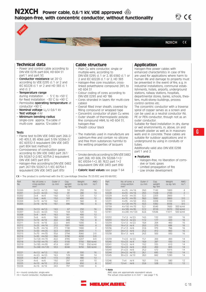
N2XCH Power cable, 0,6/1 kV, VDE approvedhalogen-free, with concentric conductor, without functionality
Technical data– Power and control cable according toDIN VDE 0276 part 604, HD 604 S1part 1 and part 5G
– Conductor resistance (at 208C)according to VDE 0295 cl. 1 or 2 andIEC 60228 cl. 1 or 2 and HD 383 cl. 1and cl. 2
– Temperature rangeduring installation – 58C to +508Cfor fixed installation –308C to +908C
– Permissible operating temperature atconductor +908C
– Nominal voltage U0/U 0,6/1 kV– Test voltage 4 kV– Minimum bending radiussingle-core approx. 15xcable 1
multi-core approx. 12xcable 1
Tests– Flame test to DIN VDE 0482 part 266-2/HD 405.3, BS 4066 part 3/EN 50266-2/IEC 60332-3 (equivalent DIN VDE 0472part 804 test method C)
– Corrosiveness of combustion gasesaccording to DIN VDE 0482 part 267/EN 50267-2-2/IEC 60754-2 (equivalentDIN VDE 0472 part 813)
– Halogen-free according toDIN VDE 0482part 267/EN 50267-2-1/IEC 60754-1(equivalent DIN VDE 0472 part 815)
Cable structure– Plain Cu wire conductor, single ormultiple-wire, according toDIN VDE 0295 cl. 1 or 2, BS 6360 cl. 1 or2 and IEC 60228 cl. 1 or 2, HD 383
– Halogen-free core insulation, cross-linked polyethylene compound 2XI1, toHD 604 S1
– Colour coding of cores according toDIN VDE 0293 and HD 186
– Cores stranded in layers (for multi-corecables)
– Overall filled inner sheath, covered byfilling compound or wrapped tape
– Concentric conductor of plain Cu wires– Outer sheath of thermoplastic polyole-fine compound HM4, to HD 604 S1,halogen-free
– Sheath colour black
– The materials used in manufacture arecadmium-free and contain no siliconeand free from substances harmful tothe wetting properties of lacquers
– Smokedensity according to DIN VDE0482part 268, HD 606, EN 50268-1+2/IEC 61034-1+2, BS 7622 part 1+2(equivalent DIN VDE 0472 part 816)
– Caloric load values see page T 64
ApplicationHalogen-free power cables withenhanced characteristics in case of fireare used for applications where harm tohuman life and damage to property mustbe prevented in the event of fire, e.g. inindustrial installations, communal estab-lishments, hotels, airports, undergroundstations, railway stations, hospitals,departmental stores, banks, schools, thea-ters, multi-storey buildings, processcontrol centres etc.The concentric conductor with a traversespiral of copper serves as a screen andcan be used as a neutral conductor (N),PE or PEN conductor, though not as anouter conductor.Suitable for fixed installation in dry, dampor wet environments, in, above, on andbeneath plaster as well as in masonarywalls and in concrete. These cables aresuitable for outdoor applications and inunderground by using in conduits ortubes.Additionally valid also DIN VDE 0298part 1 and 2.
* Features– Halogen-free, no liberation of corro-sive or toxic gases
– Limited propagation of fire– Low smoke development
= The product is conformed with the EC Low-Voltage Directive 73/23/EEC and 93/68/EEC.
PartNo.
No. of cores xcross-sectionmm2
Outer 1ca. mm
Cop.weightkg/km
Weightca. kg/km
AWG-no.*)
53200 2 x 1,5 re/1,5 14,0 53 250 1653201 2 x 2,5 re/2,5 15,0 81 280 1453202 2 x 4 re/4 14,0 122 320 1253203 2 x 6 re/6 15,0 183 400 1053204 2 x 10 re/10 16,0 311 560 853205 2 x 16 re/16 19,1 490 780 6
53206 3 x 1,5 re/1,5 14,5 67 250 1653207 3 x 2,5 re/2,5 15,5 104 320 1453208 3 x 4 re/4 16,5 161 400 1253209 3 x 6 re/6 18,0 242 500 1053210 3 x 10 re/10 20,0 408 750 853211 3 x 16 re/16 22,5 643 1000 653212 3 x 25 rm/16 27,0 1001 1600 453213 3 x 35 rm/16 27,5 1190 1900 253214 3 x 50 rm/25 32,3 2003 2400 153215 3 x 70 rm/35 35,6 2794 3060 2/053216 3 x 95 rm/50 39,0 3790 4200 3/053217 3 x 120 rm/70 42,0 4785 5207 4/053218 3 x 150 rm/70 43,5 5100 5700 300 kcmil53219 3 x 185 rm/95 47,4 6381 7150 350 kcmil53220 3 x 240 rm/120 53,5 8240 9250 500 kcmil
53221 4 x 1,5 re/1,5 15,5 81 300 1653222 4 x 2,5 re/2,5 16,5 129 380 1453223 4 x 4 re/4 17,5 202 480 1253224 4 x 6 re/6 19,0 297 600 1053225 4 x 10 re/10 21,5 504 850 853226 4 x 16 re/16 24,5 797 1200 6
PartNo.
No. of cores xcross-sectionmm2
Outer 1ca. mm
Cop.weightkg/km
Weightca. kg/km
AWG-no.*)
53227 4 x 25 rm/16 29,0 1142 1800 453228 4 x 35 rm/16 29,5 1528 2100 253229 4 x 50 rm/25 32,5 2203 2800 153230 4 x 70 rm/35 38,0 3082 3800 2/053231 4 x 95 rm/50 43,5 4208 5100 3/053758 4 x 120 rm/70 50,5 5382 6556 4/053759 4 x 150 rm/70 52,1 6540 7600 300 kcmil53760 4 x 185 rm/95 57,2 8159 9370 350 kcmil53761 4 x 240 rm/120 62,6 10546 11611 500 kcmil
53232 7 x 1,5 re/2,5 14,5 132 320 1653233 10 x 1,5 re/2,5 17,2 177 420 1653234 12 x 1,5 re/2,5 18,4 204 460 1653235 16 x 1,5 re/4 20,0 275 686 1653236 21 x 1,5 re/6 22,6 370 766 1653237 24 x 1,5 re/6 23,2 412 860 1653238 30 x 1,5 re/6 24,3 500 930 16
53239 7 x 2,5 re/2,5 15,1 200 400 1453240 10 x 2,5 re/4 18,9 287 550 1453241 12 x 2,5 re/4 19,2 335 610 1453242 16 x 2,5 re/6 20,9 450 805 1453243 21 x 2,5 re/6 25,2 572 1015 1453244 24 x 2,5 re/10 26,1 695 1100 1453245 30 x 2,5 re/10 28,0 842 1290 14
53246 7 x 4 re/4 18,1 316 580 1253247 12 x 4 re/6 22,6 528 910 12
re = round conductor, single-wirerm = round conductor, multiple-wire
*) NoteAWG sizes are approximate equivalent values.The actual cross-section is in mm2 – see page T 15.
�G 13
G

N2XH-FE 180/E 30Security Cable, halogen-free, 0,6/1 kVwith improved fire characteristics
Technical data– Halogen-free security cable withimproved characteristics in the case offire to DIN VDE 0266
– Insulation integrity 180 minutes toDIN VDE 0472 part 814
– Functionality 30 minutes toDIN VDE 4102 part 12
– Temperature range–308C to +708C
– Permissible operating temperature atconductor +908C
– Nominal voltage U0/U 0,6/1 kV– Test voltage 4000 V– Minimum bending radiusapprox. 15xcable 1
– Radiation resistanceup to 200x106 cJ/kg (up to 200 Mrad)
Tests– Flame test to DIN VDE 0482 part 266-2/HD 405.3, BS 4066 part 3/EN 50266-2/IEC 60332-3 (equivalent DIN VDE 0472part 804 test method C)
– Corrosiveness of combustion gasesaccording to DIN VDE 0482 part 267/EN 50267-2-2/IEC 60754-2 (equivalentDIN VDE 0472 part 813)
– Halogen-free according toDIN VDE 0482part 267/EN 50267-2-1/IEC 60754-1(equivalent DIN VDE 0472 part 815)
– Smokedensity according to DIN VDE0482part 268, HD 606, EN 50268-1+2/IEC 61034-1+2, BS 7622 part 1+2(equivalent DIN VDE 0472 part 816)
– Insulation integrity under flame propa-gation to VDE 0472 part 814 = IEC 60331
– Burning behaviour in fire(functionality) of the complete cablesystem to DIN 4102 part 12 (30 minutes)
– Caloric load values see page T 65
Cable structure– Bare copper conductor, solid orstranded, to DIN VDE 0295 cl. 1 or cl. 2,BS 6360 cl. 1 or 2, IEC 60228 cl. 1/2,HD 383
– Core with double insulation:* Flame retardant MICA-tapeover conductor
* Core insulation with cross-linked poly-ethylene, compound type 2XI1 toDIN VDE 0276 part 604
– Cores colour coding to DIN VDE 0293and 0276 part 604
– Green-yellow earth-core, 3 cores andabove
– Cores stranded in layers– Overall core covering, halogen-freefilling compound, pressed
– Outer jacket of thermoplastic halogen-free polyolefine, compound type HM4to DIN VDE 0276 part 604, flame retar-dant, colour orange
Advantages– Halogen-free; no evolution of corrosiveand toxic gases
– Flame retardant– Hardly flammable– Self-extinguished and fire resistant– No flame propagation, thereforesecurity from fire
– Low smoke density, no darkening ofemergency exits without hindering thefire extinguishing works
– Toxicological harmless– No self-ignition– Maintenance of functionality during theincreased current load
* FE 180: Insulation integrity for180 minutes. Tests to DIN VDE 0472part 814 = IEC 60331.Insulation integrity under directflame propagation for the test periodof 180 minutes.
ApplicationSecurity cables are ideal for use every-where, where in case of fire human lifeand material assets are to be protectedand safety conciousness take a specialsignificance, e.g. in industrial complexes,power stations, communal establishment,hotels, airports, underground railway net-works, hospitals and outpatients clinic(DIN VDE 0107), department stores, dataprocessing centres, theaters, cinemas, inmulti-storey buildings, public gatherings,schools etc. (DIN VDE 0108), mining works,offshore plants, leading centres, trafficcommunication, emergency power supplyand alarm systems. The cables are suit-able for fixed installation in dry and moistrooms, in, above, on and beneath plasteras well as in masonary walls and in con-crete. These cables are suitable for out-door applications and in underground byusing in conduits or tubes.Additionally valid also DIN VDE 0298part 1 and 2.For the installation in conduit all precau-tions must be taken that no accumula-tion of water can occur in the pipes.
* E 30: Functionality of electrical cablesystems for minimum 30 minutes. Testto DIN 4102 part 12. This fulfils thedemands of technical guide lines forfire protection (supplement 1 toDIN VDE 0108 part 1).The functionality for 30 minutesassures when persons and animals areto be saved from a burning building.30 minutes secures the functional per-formance of the fire warning and alarmsystems, safety and spare lighting, pas-senger lifts with evacuation circuits, ex-cept the cables which are installed withinthe ladder shafts and engine rooms.
= The product is conformed with the EC Low-Voltage Directive 73/23/EEC and 93/68/EEC.
PartNo.
No. of cores xcross-sectionmm2
Outer 1ca. mm
Cop.weightkg/km
Weightca. kg/km
AWG-no.*)
52058 1 x 4 re 8,0 38 155 1252059 1 x 6 re 9,0 58 190 1052060 1 x 10 re 10,0 96 215 852061 1 x 16 re 10,5 154 240 652062 1 x 25 rm 13,0 240 380 452063 1 x 35 rm 14,0 336 460 252064 1 x 50 rm 15,5 480 590 152065 1 x 70 rm 17,5 672 820 2/052066 1 x 95 rm 19,5 912 1090 3/052067 1 x 120 rm 21,0 1152 1350 4/052068 1 x 150 rm 23,0 1440 1650 300 kcmil52069 1 x 185 rm 25,0 1776 2030 350 kcmil52070 1 x 240 rm 29,0 2304 2590 500 kcmil
PartNo.
No. of cores xcross-sectionmm2
Outer 1ca. mm
Cop.weightkg/km
Weightca. kg/km
AWG-no.*)
52071 2 x 1,5 re 11,5 29 170 1652072 2 x 2,5 re 12,0 48 190 1452073 2 x 4 re 13,0 77 260 1252074 2 x 6 re 14,0 115 310 1052075 2 x 10 re 15,5 192 430 852076 2 x 16 re 17,5 307 600 652077 2 x 25 rm 22,0 480 930 4
re = round conductor, single-wirerm = round conductor, multiple-wire
*) Note Continuation "
AWG sizes are approximate equivalent values.The actual cross-section is in mm2
– see page T 15.
�G 14

N2XH-FE 180/E 30Security Cable, halogen-free, 0,6/1 kVwith improved fire characteristics
= The product is conformed with the EC Low-Voltage Directive 73/23/EEC and 93/68/EEC.
PartNo.
No. of cores xcross-sectionmm2
Outer 1ca. mm
Cop.weightkg/km
Weigthca. kg/km
AWG-no.*)
52078 3 x 1,5 re 12,0 43 170 1652079 3 x 2,5 re 12,5 72 220 1452080 3 x 4 re 13,5 115 290 1252081 3 x 6 re 14,5 173 370 1052082 3 x 10 re 16,5 288 530 852083 3 x 16 re 18,5 461 760 652084 3 x 25 rm 23,5 720 1160 452085 3 x 35 rm 26,0 1080 1560 252086 3 x 50 rm 29,0 1440 2030 152087 3 x 70 rm 34,0 2016 2890 2/052088 3 x 25/16 rm 22,5 874 1430 452089 3 x 35/16 rm 28,0 1162 1810 252090 3 x 50/25 rm 32,0 1680 2340 152091 3 x 70/35 rm 35,0 2352 3190 2/052092 3 x 95/50 rm 40,0 3216 4350 3/052093 3 x 120/70 rm 45,0 4128 5550 4/052094 3 x 150/70 rm 48,5 4992 6560 300 kcmil52095 3 x 185/95 rm 54,0 6240 8240 350 kcmil
PartNo.
No. of cores xcross-sectionmm2
Outer 1ca. mm
Cop.weightkg/km
Weigthca. kg/km
AWG-no.*)
52096 4 x 1,5 re 12,5 58 210 1652097 4 x 2,5 re 13,0 96 260 1452614 4 x 4 re 13,0 154 310 1252615 4 x 6 re 14,5 230 410 1052616 4 x 10 re 16,0 384 620 852617 4 x 16 re 18,0 614 900 6
52618 5 x 1,5 re 12,0 72 210 1652619 5 x 2,5 re 13,0 120 280 1452620 5 x 4 re 14,5 192 380 1252621 5 x 6 re 15,5 288 510 1052622 5 x 10 re 18,0 480 760 852623 5 x 16 re 20,0 768 1120 6
52624 7 x 1,5 re 13,0 101 250 16
52625 12 x 1,5 re 16,5 173 390 16
re = round conductor, single-wirerm = round conductor, multiple-wire
*) NoteAWG sizes are approximate equivalent values.The actual cross-section is in mm2
– see page T 15.
�G 15
G

N2XCH-FE 180/E 30Security Cable, halogen-free, 0,6/1 kVwith improved fire characteristics
Technical data– Halogen-free security cable withimproved characteristics in the case offire to DIN VDE 0266
– Insulation integrity 180 minutes toDIN VDE 0472 part 814
– Functionality 30 minutes toDIN VDE 4102 part 12
– Temperature range–308C to +708C
– Permissible operating temperature atconductor +908C
– Nominal voltage U0/U 0,6/1 kV– Test voltage 4000 V– Minimum bending radiusapprox. 15xcable 1
– Radiation resistanceup to 200x106 cJ/kg (up to 200 Mrad)
Tests– Flame test to DIN VDE 0482 part 266-2/HD 405.3, BS 4066 part 3/EN 50266-2/IEC 60332-3 (equivalent DIN VDE 0472part 804 test method C)
– Corrosiveness of combustion gasesaccording to DIN VDE 0482 part 267/EN 50267-2-2/IEC 60754-2 (equivalentDIN VDE 0472 part 813)
– Halogen-free according toDIN VDE 0482part 267/EN 50267-2-1/IEC 60754-1(equivalent DIN VDE 0472 part 815)
– Smokedensity according to DIN VDE0482part 268, HD 606, EN 50268-1+2/IEC 61034-1+2, BS 7622 part 1+2(equivalent DIN VDE 0472 part 816)
– Insulation integrity under flame propa-gation to VDE 0472 part 814 = IEC 60331
– Burning behaviour in fire(functionality) of the complete cablesystem to DIN 4102 part 12 (30 minutes)
– Caloric load values see page T 65
Cable structure– Bare copper conductor, solid orstranded, to DIN VDE 0295 cl. 1 or cl. 2,BS 6360 cl. 1 or 2, IEC 60228 cl. 1 or 2,HD 383
– Core with double insulation:* Flame retardant MICA-tapeover conductor
* Core insulation with cross-linked poly-ethylene, compound type 2XI1 toDIN VDE 0276 part 604
– Cores colour coding to DIN VDE 0293and 0276 part 604
– Cores stranded in layers– Overall core covering, halogen-freefilling compound, pressed
– Concentric conductor of Cu-bare wireswith helix of copper tape
– Outer jacket of thermoplastic halogen-free polyolefine, compound type HM4to DIN VDE 0276 part 604, flame retar-dant, colour orange
Advantages– Halogen-free; no evolution of corrosiveand toxic gases
– Flame retardant / Hardly flammable– Self-extinguished and fire resistant– No flame propagation, thereforesecurity from fire
– Low smoke density, no darkening ofemergency exits without hindering thefire extinguishing works
– Toxicological harmless– No self-ignition– Maintenance of functionality during theincreased current load
* FE 180: Insulation integrity for180 minutes. Tests to DIN VDE 0472part 814 = IEC 60331.Insulation integrity under directflame propagation for the test periodof 180 minutes.
ApplicationEverywhere, where in case of fire humanlife and material assets are to be protectedand safety conciousness take a specialsignificance, e.g. in industrial complexes,power stations, communal establishment,hotels, airports, underground railway net-works, hospitals and outpatients clinic(DIN VDE 0107), department stores, dataprocessing centres, theaters, cinemas, inmulti-storey buildings, public gatherings,schools etc. (DIN VDE 0108), mining works,offshore plants, leading centres, trafficcommunication, emergency power supplyand alarm systems. Suitable for fixed instal-lation in dry and moist rooms, in, above,on and beneath plaster as well as in ma-sonary walls and in concrete. These cablesare suitable for outdoor applications andin underground by using in conduits ortubes. Additionally valid also DIN VDE 0298part 1 and 2. For the installation in conduitall precautions must be taken that noaccumulation of water can occur in thepipes.
* E 30: Functionality of electrical cablesystems for minimum 30 minutes. Testmethod to DIN 4102 part 12. This fulfilsthe demands of technical guide linesfor fire protection (supplement 1 toDIN VDE 0108 part 1).The functionality for 30 minutesassures when persons and animals areto be saved from a burning building.30 minutes secures the functional per-formance of the fire warning and alarmsystems, safety and spare lighting, pas-senger lifts with evacuation circuits, ex-cept the cables which are installed withinthe ladder shafts and engine rooms.
= The product is conformed with the EC Low-Voltage Directive 73/23/EEC and 93/68/EEC.
PartNo.
No. of cores xcross-sectionmm2
Outer 1ca. mm
Cop.weightkg/km
Weightca. kg/km
AWG-no.*)
52098 2 x 1,5/1,5 re 13,0 52 200 1652099 2 x 2,5/2,5 re 14,0 80 250 1452100 2 x 4/4 re 15,0 123 310 1252101 2 x 6/6 re 16,0 182 400 1052102 2 x 10/10 re 17,5 312 570 8
52103 3 x 1,5/1,5 re 13,0 66 220 1652104 3 x 2,5/2,5 re 14,0 104 270 1452105 3 x 4/4 re 15,5 161 360 1252106 3 x 6/6 re 16,5 240 470 1052107 3 x 10/10 re 18,5 408 680 8
PartNo.
No. of cores xcross-sectionmm2
Outer 1ca. mm
Cop.weightkg/km
Weightca. kg/km
AWG-no.*)
52108 3 x 16/16 re 21,0 643 960 652109 3 x 25/16 rm 25,5 902 1390 452110 3 x 35/16 rm 29,0 1190 1720 252111 3 x 50/25 rm 31,5 1723 2320 152112 3 x 70/35 rm 36,5 2410 3260 2/052113 3 x 95/50 rm 40,0 3296 4310 3/052114 3 x 120/70 rm 46,0 4236 5520 4/052115 3 x 150/70 rm 50,5 5100 6620 300 kcmil52116 3 x 185/95 rm 55,0 6383 8180 350 kcmil52117 3 x 240/120 rm 61,5 8242 10620 500 kcmil
Continuation "
re = round conductor, single-wirerm = round conductor, multiple-wire
*) NoteAWG sizes are approximate equivalent values.The actual cross-section is in mm2 – see page T 15.
�G 16

N2XCH-FE 180/E 30Security Cable, halogen-free, 0,6/1 kVwith improved fire characteristics
= The product is conformed with the EC Low-Voltage Directive 73/23/EEC and 93/68/EEC.
PartNo.
No. of cores xcross-sectionmm2
Outer 1ca. mm
Cop.weightkg/km
Weigthca. kg/km
AWG-no.*)
52118 4 x 1,5/1,5 re 15,0 81 260 1652119 4 x 2,5/2,5 re 16,0 128 310 1452120 4 x 4/4 re 17,0 200 420 1252121 4 x 6/6 re 18,0 297 540 1052122 4 x 10/10 re 20,0 504 800 852123 4 x 16/16 re 22,5 796 1150 652124 4 x 25/16 rm 28,0 1142 1670 452125 4 x 35/16 rm 30,5 1526 2160 252126 4 x 50/25 rm 32,0 2203 2860 1
PartNo.
No. of cores xcross-sectionmm2
Outer 1ca. mm
Cop.weightkg/km
Weigthca. kg/km
AWG-no.*)
52127 4 x 70/35 rm 39,5 3082 3980 2/052128 4 x 95/50 rm 43,5 4208 5300 3/052129 4 x 120/70 rm 49,5 5388 6740 4/052130 4 x 150/70 rm 55,5 6558 8210 300 kcmil52131 4 x 185/95 rm 60,0 8159 10200 350 kcmil52132 4 x 240/120 rm 68,0 10546 12900 500 kcmil
52133 7 x 1,5/2,5 re 16,5 133 360 1652134 30 x 1,5/6 re 29,0 499 1070 16
re = round conductor, single-wirerm = round conductor, multiple-wire
*) NoteAWG sizes are approximate equivalent values.The actual cross-section is in mm2
– see page T 15.
�G 17
G

NHXH-FE 180/E 30Security Cable, halogen-free, 0,6/1 kVwith improved fire characteristics
Technical data– Halogen-free security cable withimproved characteristics in the case offire to DIN VDE 0266
– Insulation integrity 180 minutes toDIN VDE 0472 part 814
– Functionality 30 minutes toDIN VDE 4102 part 12
– Temperature range–308C to +708C
– Permissible operating temperatureat conductor +908C
– Nominal voltage U0/U 0,6/1 kV– Test voltage 4000 V– Minimum bending radiusapprox. 15xcable 1
– Radiation resistanceup to 200x106 cJ/kg (up to 200 Mrad)
Tests– Flame-test to VDE 0472 part 804, testmethod C, IEC 60332-3 cat. C andHD 405.3
– Corrosiveness of combustion gases toVDE 0472 part 813, IEC 60754-2 andHD 602
– Halogen-free to VDE 0472 part 815 andIEC 60754-1
– Smoke density to VDE 0472 part 816,test method C, IEC 61034-1/61034-2,HD 606 and BS 7622 part 1 and 2
– Insulation integrity under flame propa-gation to VDE 0472 part 814 = IEC 60331
– Burning behaviour in fire(functionality) of the complete cablesystem to DIN 4102 part 12 (30 minutes)
– Caloric load values see page T 65
Cable structure– Bare copper conductor, solid orstranded, to DIN VDE 0295 cl. 1 or cl. 2
– Double core insulation of mica tapeand cross-linked polymer HI1, toDIN VDE 0207 part 23
– Colour coding of cores according toDIN VDE 0293
– Green-yellow earth-core, 3 cores andabove
– Cores stranded in layer– Core wrapping with glass-fibre tape asflame-protection
– Outer jacket orange, polymer-compound DIN VDE 0207 part 24,flame retardant
Advantages– Halogen-free; no evolution of corrosiveand toxic gases
– Flame retardant– Hardly flammable– Self-extinguished and fire resistant– No flame propagation, thereforesecurity from fire
– Low smoke density, no darkening ofemergency exits without hindering thefire extinguishing works
– Toxicological harmless– No self-ignition– Maintenance of functionality during theincreased current load
* FE 180: Insulation integrity for180 minutes. Tests to DIN VDE 0472part 814 = IEC 60331.Insulation integrity under directflame propagation for the test periodof 180 minutes.
ApplicationSecurity cables are ideal for use every-where, where in case of fire human lifeand material assets are to be protectedand safety conciousness take a specialsignificance, e.g. in industrial complexes,power stations, communal establishment,hotels, airports, underground railway net-works, hospitals and outpatients clinic(DIN VDE 0107), department stores, dataprocessing centres, theaters, cinemas, inmulti-storey buildings, public gatherings,schools etc. (DIN VDE 0108), mining works,offshore plants, leading centres, trafficcommunication, emergency power supplyand alarm systems. The cables are suit-able for fixed installation in dry and moistrooms, in, above, on and beneath plasteras well as in masonary walls and in con-crete. These cables are suitable for out-door applications and in underground byusing in conduits or tubes.Additionally valid also DIN VDE 0298part 1 and 2.For the installation in conduit all precau-tions must be taken that no accumula-tion of water can occur in the pipes.
* E 30: Functionality of electrical cablesystems for minimum 30 minutes. Testto DIN 4102 part 12. This fulfils thedemands of technical guide lines forfire protection (supplement 1 toDIN VDE 0108 part 1).The functionality for 30 minutesassures when persons and animals areto be saved from a burning building.30 minutes secures the functional per-formance of the fire warning and alarmsystems, safety and spare lighting, pas-senger lifts with evacuation circuits, ex-cept the cables which are installed withinthe ladder shafts and engine rooms.
= The product is conformed with the EC Low-Voltage Directive 73/23/EEC and 93/68/EEC.
PartNo.
No. of cores xcross-sectionmm2
Outer 1ca. mm
Cop.weightkg/km
Weightca. kg/km
AWG-no.*)
52700 1 x 4 re 7,0 38 98 1252701 1 x 6 re 7,5 58 125 1052702 1 x 10 re 8,0 96 165 852703 1 x 16 rm 9,0 154 230 652704 1 x 25 rm 10,5 240 345 452705 1 x 35 rm 11,5 336 450 252706 1 x 50 rm 12,0 480 590 152707 1 x 70 rm 15,0 672 800 2/052708 1 x 95 rm 16,5 912 1100 3/052709 1 x 120 rm 18,5 1152 1350 4/052710 1 x 150 rm 20,5 1440 1650 300 kcmil
PartNo.
No. of cores xcross-sectionmm2
Outer 1ca. mm
Cop.weightkg/km
Weightca. kg/km
AWG-no.*)
52711 1 x 185 rm 23,0 1776 2000 350 kcmil52712 1 x 240 rm 25,5 2304 2650 500 kcmil52713 1 x 300 rm 31,8 2880 3200 600 kcmil
52714 OB 2 x 2,5 re 12,5 48 290 1452715 OB 2 x 4 re 13,5 77 345 1252716 OB 2 x 6 re 14,5 115 410 1052717 OB 2 x 10 re 16,0 192 540 852718 OB 2 x 16 rm 18,0 307 720 652719 OB 2 x 25 rm 21,0 480 1100 452720 OB 2 x 35 rm 24,0 672 1120 2
Continuation "
re = round conductor, single-wirerm = round conductor, multiple-wire
*) NoteAWG sizes are approximate equivalent values.The actual cross-section is in mm2 – see page T 15.
�G 18

NHXH-FE 180/E 30Security Cable, halogen-free, 0,6/1 kVwith improved fire characteristics
= The product is conformed with the EC Low-Voltage Directive 73/23/EEC and 93/68/EEC.
PartNo.
No. of cores xcross-sectionmm2
Outer 1ca. mm
Cop.weightkg/km
Weightca. kg/km
AWG-no.*)
52721 3 x 1,5 re 12,5 43 280 1652722 3 x 2,5 re 13,5 72 330 1452723 3 x 4 re 14,5 115 400 1252724 3 x 6 re 15,5 173 480 1052725 3 x 10 re 17,0 288 650 852726 3 x 16 rm 19,0 461 850 652727 3 x 25 rm 22,5 720 1300 452728 3 x 35 rm 24,5 1080 1700 252729 3 x 50 rm 27,5 1440 2200 152730 3 x 70 rm 32,0 2016 3000 2/052731 3 x 95 rm 35,5 2736 4000 3/052732 3 x 120 rm 39,5 3456 4850 4/052733 3 x 150 rm 44,0 4320 5950 300 kcmil52734 3 x 185 rm 49,5 5328 7450 350 kcmil52735 3 x 240 rm 60,0 6910 8600 500 kcmil
52736 4 x 1,5 re 13,5 58 325 1652737 4 x 2,5 re 14,0 96 385 1452738 4 x 4 re 15,5 154 470 1252739 4 x 6 re 16,5 230 580 1052740 4 x 10 re 18,5 384 790 852741 4 x 16 rm 20,5 614 1100 652742 4 x 25 rm 24,5 960 1650 452743 4 x 35 rm 27,0 1344 2150 252744 4 x 50 rm 30,0 1920 2800 152745 4 x 70 rm 35,0 2688 3800 2/052746 4 x 95 rm 39,5 3648 5050 3/052747 4 x 120 rm 43,5 4608 6150 4/052748 4 x 150 rm 49,0 5760 7650 300 kcmil
PartNo.
No. of cores xcross-sectionmm2
Outer 1ca. mm
Cop.weightkg/km
Weightca. kg/km
AWG-no.*)
52749 5 x 1,5 re 14,0 72 375 1652750 5 x 2,5 re 15,0 120 445 1452751 5 x 4 re 16,5 192 560 1252752 5 x 6 re 18,0 288 690 1052753 5 x 10 re 20,0 480 950 852754 5 x 16 rm 22,5 768 1300 652755 5 x 25 rm 26,5 1200 1980 452756 5 x 35 rm 36,0 1680 2600 2
52757 7 x 1,5 re 15,0 101 365 1652758 7 x 2,5 re 16,5 168 540 14
52759 10 x 1,5 re 18,0 144 580 1652760 10 x 2,5 re 20,0 240 710 14
52761 12 x 1,5 re 19,0 173 640 1652762 12 x 2,5 re 20,5 288 790 14
52763 14 x 1,5 re 20,0 202 740 1652764 14 x 2,5 re 21,5 336 880 14
52765 19 x 1,5 re 21,5 274 880 1652766 19 x 2,5 re 23,5 456 1150 14
52767 24 x 1,5 re 25,0 346 1100 1652768 24 x 2,5 re 27,0 576 1400 14
52769 30 x 1,5 re 26,0 432 1300 1652770 30 x 2,5 re 28,5 720 1650 14
Burn-test Burn-test chamber
re = round solid corerm = round strandet core Further cross-sections in stock available on request.
*) NoteAWG sizes are approximate equivalent values.The actual cross-section is in mm2
– see page T 15.
�G 19
G

NHXCH-FE 180/E 30Security Cable, halogen-free, 0,6/1 kVwith improved fire characteristics
Technical data– Halogen-free security cable withimproved characteristics in the case offire to DIN VDE 0266
– Insulation integrity 180 minutes toDIN VDE 0472 part 814
– Functionality 30 minutes toDIN VDE 4102 part 12
– Permissible operating temperatureat conductor +908C
– Nominal voltage U0/U 0,6/1 kV– Test voltage 4000 V– Minimum bending radiusapprox. 15xcable 1
– Radiation resistanceup to 200x106 cJ/kg (up to 200 Mrad)
Tests– Flame test to DIN VDE 0482 part 266-2/HD 405.3, BS 4066 part 3/EN 50266-2/IEC 60332-3 (equivalent DIN VDE 0472part 804 test method C)
– Corrosiveness of combustion gasesaccording to DIN VDE 0482 part 267/EN 50267-2-2/IEC 60754-2 (equivalentDIN VDE 0472 part 813)
– Halogen-free according toDIN VDE 0482part 267/EN 50267-2-1/IEC 60754-1(equivalent DIN VDE 0472 part 815)
– Smokedensity according to DIN VDE0482part 268, HD 606, EN 50268-1+2/IEC 61034-1+2, BS 7622 part 1+2(equivalent DIN VDE 0472 part 816)
– Insulation integrity under flame propa-gation to VDE 0472 part 814 = IEC 60331
– Burning behaviour in fire(functionality) of the complete cablesystem to DIN 4102 part 12 (30 minutes)
– Caloric load values see page T 65
Cable structure– Bare copper conductor, solid orstranded, to DIN VDE 0295 cl. 1 or cl. 2,BS 6360 cl. 1 or 2, IEC 60228 cl. 1 orcl. 2, HD 383
– Special core insulation of mica tapeand cross-linked polymer HI1 toDIN VDE 0207 part 23
– Core stranded in layer– Core wrapping with glass-fibre tape– Copper wire screening with helix ofcopper tape
– Separator of special tape– Outer jacket orange, polymer-compound HM4, to DIN VDE 0207part 24, flame retardant
* FE 180: Insulation integrity for180 minutes. Tests to DIN VDE 0472part 814 = IEC 60331.Insulation integrity under directflame propagation for the test periodof 180 minutes.
* E 30: Functionality of electrical cablesystems for minimum 30 minutes. Testmethod to DIN 4102 part 12. This fulfilsthe demands of technical guide linesfor fire protection (supplement 1 toDIN VDE 0108 part 1).The functionality for 30 minutesassures when persons and animals areto be saved from a burning building. 30minutes secures the functional perfor-mance of the fire warning and alarm sys-tems, safety and spare lighting, passen-ger lifts with evacuation circuits, exceptthe cables which are installed within theladder shafts and engine rooms.
ApplicationEverywhere, where in case of fire humanlife and material assets are to be protectedand safety conciousness take a specialsignificance, e.g. in industrial complexes,power stations, communal establishment,hotels, airports, underground railway net-works, hospitals and outpatients clinic(DIN VDE 0107), department stores, dataprocessing centres, theaters, cinemas, inmulti-storey buildings, public gatherings,schools etc. (DIN VDE 0108), mining works,offshore plants, leading centres, trafficcommunication, emergency power supplyand alarm systems. Suitable for fixed instal-lation in dry and moist rooms, in, above,on and beneath plaster as well as in ma-sonary walls and in concrete. These cablesare suitable for outdoor applications andin underground by using in conduits ortubes. Additionally valid also DIN VDE 0298part 1 and 2. For the installation in conduitall precautions must be taken that no accu-mulation of water can occur in the pipes.Advantages– Halogen-free; no evolution of corrosiveand toxic gases
– Flame retardant / Hardly flammable– Self-extinguished and fire resistant– No flame propagation, thereforesecurity from fire
– Low smoke density, no darkening ofemergency exits without hindering thefire extinguishing works
– Toxicological harmless– No self-ignition– Maintenance of functionality during theincreased current load
= The product is conformed with the EC Low-Voltage Directive 73/23/EEC and 93/68/EEC.
PartNo.
No. of cores xcross-sectionmm2
Outer 1ca. mm
Cop.weightkg/km
Weightca. kg/km
AWG-no.*)
52900 OB 2 x 1,5/1,5 re 15,0 52 220 1652901 OB 2 x 2,5/2,5 re 13,5 80 385 1452902 OB 2 x 4/4 re 14,5 123 470 1252903 OB 2 x 6/6 re 16,0 182 550 1052904 OB 2 x 10/10 re 18,0 312 730 8
52905 3 x 1,5/1,5 re 13,5 66 380 1652906 3 x 2,5/2,5 re 14,5 104 430 1452907 3 x 4/4 re 15,5 161 530 1252908 3 x 6/6 re 16,5 240 630 1052909 3 x 10/10 re 18,5 408 850 852910 3 x 16/16 rm 20,5 643 1150 652911 3 x 25/16 rm 24,0 902 1700 452912 3 x 35/16 rm 26,5 1190 2150 252913 3 x 50/25 rm 29,5 1723 2800 152914 3 x 70/35 rm 33,0 2410 3800 2/052915 3 x 95/50 rm 37,5 3296 5100 3/052916 3 x 120/70 rm 42,5 4236 6250 4/052917 3 x 150/70 rm 47,0 5100 6900 300 kcmil52918 3 x 185/95 rm 52,5 6383 8550 350 kcmil52919 3 x 240/120 rm 58,5 8242 11150 500 kcmil
52920 4 x 1,5/1,5 re 14,5 81 435 1652921 4 x 2,5/2,5 re 15,5 128 500 14
PartNo.
No. of cores xcross-sectionmm2
Outer 1ca. mm
Cop.weightkg/km
Weightca. kg/km
AWG-no.*)
52922 4 x 4/4 re 16,5 200 610 1252923 4 x 6/6 re 17,5 297 740 1052924 4 x 10/10 re 20,0 504 1050 852925 4 x 16/16 re 22,0 796 1350 652926 4 x 25/16 rm 26,0 1142 1950 452927 4 x 35/16 rm 28,5 1526 2400 252928 4 x 50/25 rm 32,0 2203 3200 152929 4 x 70/35 rm 37,0 3082 4300 2/052930 4 x 95/50 rm 41,5 4208 5750 3/052931 4 x 120/70 rm 47,0 5388 7100 4/052932 4 x 150/70 rm 52,0 6558 8550 300 kcmil52933 4 x 185/95 rm 58,0 8159 10700 350 kcmil52934 4 x 240/120 rm 64,0 10546 13930 500 kcmil
52935 7 x 1,5/2,5 re 16,5 133 635 1652936 7 x 2,5/2,5 re 17,5 200 680 1452937 10 x 1,5/2,5 re 19,5 176 870 1652938 10 x 2,5/4 re 21,0 286 980 1452939 12 x 1,5/2,5 re 20,0 205 1050 1652940 12 x 2,5/4 re 21,5 334 1050 1452941 24 x 1,5/6 re 26,0 413 1900 1652942 24 x 2,5/10 re 28,5 696 1900 1452943 30 x 1,5/6 re 27,0 499 2200 1652944 30 x 2,5/10 re 30,0 840 2200 14
�G 20

N2XH-FE 180/E 90Security Cable, halogen-free, 0,6/1 kVwith improved fire characteristics
Technical data– Halogen-free security cable withimproved characteristics in the case offire to DIN VDE 0266
– Insulation integrity 180 minutes toDIN VDE 0472 part 814
– Functionality 90 minutes toDIN VDE 4102 part 12
– Temperature range –308C to 708C– Permissible operating temperature atconductor +908C
– Nominal voltage U0/U 0,6/1 kV– Test voltage 4000 V– Minimum bending radiusapprox. 12xcable 1
– Radiation resistanceup to 200x106 cJ/kg (up to 200 Mrad)
Tests– Flame test to DIN VDE 0482 part 266-2/HD 405.3, BS 4066 part 3/EN 50266-2/IEC 60332-3 (equivalent DIN VDE 0472part 804 test method C)
– Corrosiveness of combustion gasesaccording to DIN VDE 0482 part 267/EN 50267-2-2/IEC 60754-2 (equivalentDIN VDE 0472 part 813)
– Halogen-free according toDIN VDE 0482part 267/EN 50267-2-1/IEC 60754-1(equivalent DIN VDE 0472 part 815)
– Smokedensity according to DIN VDE0482part 268, HD 606, EN 50268-1+2/IEC 61034-1+2, BS 7622 part 1+2(equivalent DIN VDE 0472 part 816)
– Insulation integrity under flame propa-gation to VDE 0472 part 814 = IEC 60331
– Burning behaviour in fire(functionality) of the complete cablesystem to DIN 4102 part 12 (90 minutes)
– Caloric load values see page T 65
*) NoteAWG sizes are approximate equivalent values.The actual cross-section is in mm2
– see page T 15.
Cable structure– Bare copper conductor, solid orstranded, to DIN VDE 0295 cl. 1 or cl. 2,BS 6360 cl. 1 or 2, IEC 60228 cl. 1 orcl. 2, HD 383
– Core with double insulation:* Flame retardant MICA-tapeover conductor
* Core insulation with cross-linkedpolyethylene, compound type 2XI1 toDIN VDE 0276 part 604
– Cores colour coding to DIN VDE 0293and 0276 part 604
– Green-yellow earth-core, 3 cores andabove
– Cores stranded in layers– Overall core covering, halogen-freefilling compound, pressed
– Outer jacket of thermoplastic halogen-free polyolefine, compound type HM4to DIN VDE 0276 part 604, flame retar-dant, colour orange
Advantages– Halogen-free; no evolution of corrosiveand toxic gases
– Flame retardant / Hardly flammable– Self-extinguished and fire resistant– No flame propagation, thereforesecurity from fire
– Low smoke density, no darkening ofemergency exits without hindering thefire extinguishing works
– Toxicological harmless– No self-ignition– Maintenance of functionality during theincreased current load
The functionality for 90 minutes assuresthe functional performance of water-pres-sure-rising stations for the supply toavoid smoke and heat in safety-stairs and
ApplicationEverywhere, where in case of fire humanlife and material assets are to be protectedand safety conciousness take a specialsignificance, e.g. in industrial complexes,power stations, communal establishment,hotels, airports, underground railway net-works, hospitals and outpatients clinic(DIN VDE 0107), department stores, dataprocessing centres, theaters, cinemas, inmulti-storey buildings, public gatherings,schools etc. (DIN VDE 0108), mining works,offshore plants, leading centres, trafficcommunication, emergency power supplyand alarm systems. Suitable for fixed instal-lation in dry and moist rooms, in, above,on and beneath plaster as well as in ma-sonary walls and in concrete. These cablesare suitable for outdoor applications andin underground by using in conduits ortubes. Additionally valid also DIN VDE 0298part 1 and 2. For the installation in conduitall precautions must be taken that no ac-cumulation of water can occur in the pipes.* FE 180: Insulation integrity for
180 minutes. Tests to DIN VDE 0472part 814 = IEC 60331.Insulation integrity under directflame propagation for the test periodof 180 minutes.
* E 90: Functionality of electrical cablesystems for minimum 90 minutes. Testmethod to DIN 4102 part 12. This fulfilsthe demands of technical guide linesfor fire protection (supplement 1 toDIN VDE 0108 part 1).
inner rooms, ladder shafts and enginerooms for fire brigade lifts, emergencylifts for sickbeds in hospitals and the firebrigade lifts.
= The product is conformed with the EC Low-Voltage Directive 73/23/EEC and 93/68/EEC.
PartNo.
No. of cores xcross-sectionmm2
Outer 1ca. mm
Cop.weightkg/km
Weightca. kg/km
AWG-no.*)
52534 1 x 16 rm 11,5 154 250 652535 1 x 25 rm 13,0 240 360 452536 1 x 35 rm 14,0 336 460 252537 1 x 50 rm 15,5 480 610 152538 1 x 70 rm 17,5 672 840 2/052539 1 x 95 rm 19,5 912 1120 3/052540 1 x 120 rm 21,5 1152 1390 4/052541 1 x 150 rm 23,5 1440 1690 300 kcmil52542 1 x 185 rm 25,5 1776 2090 350 kcmil52543 1 x 300 rm 31,0 2880 3350 600 kcmil52544 1 x 400 rm 34,5 3840 4230 750 kcmil
52545 2 x 1,5 re 14,5 29 270 1652546 2 x 2,5 re 15,5 48 310 1452547 2 x 4 re 16,5 77 370 1252548 2 x 6 re 17,5 115 440 1052549 2 x 10 rm 19,5 192 600 8
PartNo.
No. of cores xcross-sectionmm2
Outer 1ca. mm
Cop.weightkg/km
Weightca. kg/km
AWG-no.*)
52550 2 x 16 rm 21,0 307 780 652551 2 x 25 rm 23,5 480 1100 452552 2 x 35 rm 26,5 672 1400 252553 2 x 50 rm 30,0 960 1830 152554 2 x 70 rm 33,0 1344 2420 2/052555 2 x 95 rm 37,5 1824 3240 3/052556 2 x 120 rm 41,0 2304 3940 4/0
52557 3 x 1,5 re 15,0 43 260 1252558 3 x 2,5 re 16,0 72 350 1452559 3 x 4 re 17,0 115 420 1652560 3 x 6 re 18,0 173 520 1052561 3 x 10 rm 20,5 288 710 852562 3 x 16 rm 22,5 461 950 652563 3 x 25 rm 26,0 720 1370 452564 3 x 35 rm 28,0 1008 1750 252565 3 x 50 rm 32,0 1440 2310 1
Continuation "
�G 21
G

N2XH-FE 180/E 90Security Cable, halogen-free, 0,6/1 kVwith improved fire characteristics
= The product is conformed with the EC Low-Voltage Directive 73/23/EEC and 93/68/EEC.
PartNo.
No. of cores xcross-sectionmm2
Outer 1ca. mm
Cop.weightkg/km
Weightca. kg/km
AWG-no.*)
52566 3 x 70 rm 35,5 2016 3100 2/052567 3 x 95 rm 40,5 2736 4180 3/052568 3 x 120 rm 44,0 3456 5130 4/052569 3 x 150 rm 48,5 4320 6260 300 kcmil52570 3 x 185 rm 53,0 5328 7720 350 kcmil52571 3 x 240 rm 59,5 6912 9990 500 kcmil52572 3 x 35+1 x 16 rm 29,5 1162 1950 252573 3 x 50+1 x 25 rm 33,5 1680 2640 152574 3 x 70+1 x 35 rm 37,0 2352 3520 2/052575 3 x 95+1 x 50 rm 42,0 3216 4710 3/052576 3 x 120+1 x 70 rm 46,5 4128 5910 4/052577 3 x 150+1 x 70 rm 50,0 4992 6970 300 kcmil52578 3 x 185+1 x 95 rm 55,5 6240 8750 350 kcmil52579 3 x 240+1 x 120 rm 61,5 8064 11180 500 kcmil
52580 4 x 1,5 re 16,5 58 350 1652581 4 x 2,5 re 17,5 96 420 1452582 4 x 4 re 18,5 154 510 1252583 4 x 6 re 19,5 230 630 1052584 4 x 10 rm 22,5 384 880 852585 4 x 16 rm 24,5 614 1180 652586 4 x 25 rm 28,5 960 1730 452587 4 x 35 rm 31,0 1344 2220 252588 4 x 50 rm 35,0 1920 2940 152589 4 x 70 rm 39,0 2688 3960 2/052590 4 x 95 rm 45,0 3648 5360 3/052591 4 x 120 rm 48,5 4608 6550 4/0
PartNo.
No. of cores xcross-sectionmm2
Outer 1ca. mm
Cop.weightkg/km
Weightca. kg/km
AWG-no.*)
52592 4 x 150 rm 54,0 5760 8070 300 kcmil52593 4 x 185 rm 59,0 7104 9970 350 kcmil52594 4 x 240 rm 66,0 9216 12830 500 kcmil
52595 5 x 1,5 re 18,0 72 420 1652596 5 x 2,5 re 19,0 120 500 1452597 5 x 4 re 20,0 192 610 1252598 5 x 6 re 21,5 288 760 1052599 5 x 10 rm 24,5 480 1070 852600 5 x 16 rm 27,0 768 1450 652601 5 x 25 rm 31,0 1200 2120 452602 5 x 35 rm 34,0 1680 2730 252603 5 x 50 rm 38,5 2400 3620 152604 5 x 70 rm 43,5 3360 4940 2/0
52605 7 x 1,5 re 19,5 101 480 1652606 7 x 2,5 re 20,5 168 580 1452607 7 x 4 re 22,0 269 730 12
52608 10 x 1,5 re 24,0 144 650 1652609 10 x 2,5 re 25,5 240 790 14
52610 12 x 1,5 re 24,5 173 720 1652611 12 x 2,5 re 26,0 288 890 14
52612 24 x 1,5 re 33,0 346 1270 16
re = round conductor, single-wirerm = round conductor, multiple-wire
*) NoteAWG sizes are approximate equivalent values.The actual cross-section is in mm2
– see page T 15.
�G 22

N2XCH-FE 180/E 90Security Cable, halogen-free, 0,6/1 kVwith improved fire characteristics
Technical data– Halogen-free security cable withimproved characteristics in the case offire to DIN VDE 0266
– Insulation integrity 180 minutes toDIN VDE 0472 part 814
– Functionality 90 minutes toDIN VDE 4102 part 12
– Temperature range –308C to 708C– Permissible operating temperatureat conductor +908C
– Nominal voltage U0/U 0,6/1 kV– Test voltage 4000 V– Minimum bending radiusapprox. 12xcable 1
– Radiation resistanceup to 200x106 cJ/kg (up to 200 Mrad)
Tests– Flame test to DIN VDE 0482 part 266-2/HD 405.3, BS 4066 part 3/EN 50266-2/IEC 60332-3 (equivalent DIN VDE 0472part 804 test method C)
– Corrosiveness of combustion gasesaccording to DIN VDE 0482 part 267/EN 50267-2-2/IEC 60754-2 (equivalentDIN VDE 0472 part 813)
– Halogen-free according toDIN VDE 0482part 267/EN 50267-2-1/IEC 60754-1(equivalent DIN VDE 0472 part 815)
– Smokedensity according to DIN VDE0482part 268, HD 606, EN 50268-1+2/IEC 61034-1+2, BS 7622 part 1+2(equivalent DIN VDE 0472 part 816)
– Insulation integrity under flame propa-gation to VDE 0472 part 814 = IEC 60331
– Burning behaviour in fire(functionality) of the complete cablesystem to DIN 4102 part 12 (90 minutes)
– Caloric load values see page T 65
Cable structure– Bare copper conductor, solid orstranded, to DIN VDE 0295 cl. 1 andcl. 2, BS 6360 cl. 1 or 2, IEC 60228 cl. 1or 2, HD 383
– Core with double insulation:* Flame retardant MICA-tapeover conductor
* Core insulation with cross-linkedpolyethylene, compound type 2XI1 toDIN VDE 0276 part 604
– Cores colour coding to DIN VDE 0293and 0276 part 604
– Cores stranded in layers– Overall core covering, halogen-freefilling compound, pressed
– Concentric conductor of Cu-bare wireswith helix of copper tape
– Outer jacket of thermoplastic halogen-free polyolefine, compound type HM4to DIN VDE 0276 part 604, flame retar-dant, colour orange
Advantages– Halogen-free; no evolution of corrosiveand toxic gases
– Flame retardant– Hardly flammable– Self-extinguished and fire resistant– No flame propagation, thereforesecurity from fire
– Low smoke density, no darkening ofemergency exits without hindering thefire extinguishing works
– Toxicological harmless– No self-ignition– Maintenance of functionallity duringthe increased current load
ApplicationEverywhere, where in case of fire humanlife and material assets are to be protectedand safety conciousness take a specialsignificance, e.g. in industrial complexes,power stations, communal establishment,hotels, airports, underground railway net-works, hospitals and outpatients clinic(DIN VDE 0107), department stores, dataprocessing centres, theaters, cinemas, inmulti-storey buildings, public gatherings,schools etc. (DIN VDE 0108), mining works,offshore plants, leading centres, trafficcommunication, emergency power supplyand alarm systems. Suitable for fixed instal-lation in dry and moist rooms, in, above,on and beneath plaster as well as in ma-sonary walls and in concrete. These cablesare suitable for outdoor applications andin underground by using in conduits ortubes. Additionally valid also DIN VDE 0298part 1 and 2. For the installation in conduitall precautions must be taken that no ac-cumulation of water can occur in the pipes.
* FE 180: Insulation integrity for180 minutes. Tests to DIN VDE 0472part 814 = IEC 60331.Insulation integrity under directflame propagation for the test periodof 180 minutes.
* E 90: Functionality of electrical cablesystems for minimum 90 minutes. Testmethod to DIN 4102 part 12. This fulfilsthe demands of technical guide linesfor fire protection (supplement 1 toDIN VDE 0108 part 1).The functionality for 90 minutesassures the functional performance ofwater-pressure-rising stations for thesupply to avoid smoke and heat insafety-stairs and inner rooms, laddershafts and engine rooms for fire bri-gade lifts, emergency lifts for sickbedsin hospitals and the fire brigade lifts.
= The product is conformed with the EC Low-Voltage Directive 73/23/EEC and 93/68/EEC.
PartNo.
No. of cores xcross-sectionmm2
Outer 1ca. mm
Cop.weightkg/km
Weightca. kg/km
AWG-no.*)
52771 3 x 1,5/1,5 re 16,5 66 330 1652772 3 x 2,5/2,5 re 17,5 104 400 1452773 3 x 4/4 re 18,5 161 480 1252774 3 x 6/6 re 20,0 240 600 1052775 3 x 10/10 rm 22,0 408 840 852776 3 x 16/16 rm 24,5 643 1130 652777 3 x 25/16 rm 28,0 902 1560 452778 3 x 35/16 rm 30,5 1190 1960 252779 3 x 50/25 rm 34,0 1723 2610 152780 3 x 70/35 rm 37,5 2410 3500 2/052781 3 x 95/50 rm 43,0 3296 4700 3/0
PartNo.
No. of cores xcross-sectionmm2
Outer 1ca. mm
Cop.weightkg/km
Weightca. kg/km
AWG-no.*)
52782 3 x 120/70 rm 48,0 4236 5880 4/052783 3 x 150/70 rm 52,0 4992 7300 300 kcmil52784 3 x 185/95 rm 57,5 6383 8760 350 kcmil52785 3 x 240/120 rm 63,5 8242 11280 500 kcmil
52786 4 x 1,5/1,5 re 17,5 81 390 1652787 4 x 2,5/2,5 re 19,0 128 470 1452788 4 x 4/4 re 20,0 200 570 1252789 4 x 6/6 re 21,5 297 720 1052790 4 x 10/10 rm 24,0 504 1010 852791 4 x 16/16 rm 26,5 796 1370 6
re = round solid corerm = stranded core
Continuation "
*) NoteAWG sizes are approximate equivalent values.The actual cross-section is in mm2
– see page T 15.
�G 23
G

N2XCH-FE 180/E 90Security Cable, halogen-free, 0,6/1 kVwith improved fire characteristics
= The product is conformed with the EC Low-Voltage Directive 73/23/EEC and 93/68/EEC.
PartNo.
No. of cores xcross-sectionmm2
Outer 1ca. mm
Cop.weightkg/km
Weightca. kg/km
AWG-no.*)
52792 4 x 25/16 rm 30,5 1142 1940 452793 4 x 35/16 rm 33,0 1526 2420 252794 4 x 50/25 rm 37,5 2203 3240 152795 4 x 70/35 rm 41,5 3082 4360 2/052796 4 x 95/50 rm 47,5 4208 5900 3/052797 4 x 120/70 rm 52,5 5388 7340 4/052798 4 x 150/70 rm 57,5 6540 8840 300 kcmil52799 4 x 185/95 rm 63,5 8159 11020 350 kcmil52800 4 x 240/120 rm 70,0 10546 14140 500 kcmil
PartNo.
No. of cores xcross-sectionmm2
Outer 1ca. mm
Cop.weightkg/km
Weightca. kg/km
AWG-no.*)
52801 7 x 1,5/2,5 re 20,5 133 520 1652802 12 x 1,5/2,5 re 26,0 205 770 1652803 24 x 1,5/6 re 35,0 413 1380 1652804 30 x 1,5/6 re 37,0 499 1630 16
52805 7 x 2,5/2,5 re 22,0 200 630 1452806 12 x 2,5/4 re 28,0 334 950 1452807 24 x 2,5/10 re 37,5 696 1750 1452808 30 x 2,5/10 re 39,5 840 2080 14
re = round solid corerm = stranded core
*) NoteAWG sizes are approximate equivalent values.The actual cross-section is in mm2
– see page T 15.
�G 24

NHXH-FE 180/E 90Security Cable, halogen-free, 0,6/1 kVwith improved fire characteristics
Technical data– Halogen-free security cable withimproved characteristics in the case offire to DIN VDE 0266
– Insulation integrity 180 minutes toDIN VDE 0472 part 814
– Functionality 90 minutes toDIN VDE 4102 part 12
– Temperature range –308C to +708C– Permissible operating temperatureat conductor +908C
– Nominal voltage U0/U 0,6/1 kV– Test voltage 4000 V– Minimum bending radiusapprox. 12xcable 1
– Radiation resistanceup to 200x106 cJ/kg (up to 200 Mrad)
Tests– Flame test to DIN VDE 0482 part 266-2/HD 405.3, BS 4066 part 3/EN 50266-2/IEC 60332-3 (equivalent DIN VDE 0472part 804 test method C)
– Corrosiveness of combustion gasesaccording to DIN VDE 0482 part 267/EN 50267-2-2/IEC 60754-2 (equivalentDIN VDE 0472 part 813)
– Halogen-free according toDIN VDE 0482part 267/EN 50267-2-1/IEC 60754-1(equivalent DIN VDE 0472 part 815)
– Smokedensity according to DIN VDE0482part 268, HD 606, EN 50268-1+2/IEC 61034-1+2, BS 7622 part 1+2(equivalent DIN VDE 0472 part 816)
– Insulation integrity under flame propa-gation to VDE 0472 part 814 = IEC 60331
– Burning behaviour in fire(functionality) of the complete cablesystem to DIN 4102 part 12 (90 minutes)
– Caloric load values see page T 65
Cable structure– Bare copper conductor, solid orstranded, to DIN VDE 0295 cl. 1 or cl. 2,BS 6360 cl. 1 or 2, IEC 60228 cl. 1 orcl. 2, HD 383
– Double core insulation of mica tapeand cross-linked polymer HI1, toDIN VDE 0207 part 23
– Each single core covering with flameresistant glass-fibre tape
– Cores stranded in layer– Core wrapping with glass-fibre tape asflame-protection
– Outer jacket orange, polyolefincompound HM4, to DIN VDE 0207part 24, flame retardant
Advantages– Halogen-free; no evolution of corrosiveand toxic gases
– Flame retardant– Hardly flammable– Self-extinguished and fire resistant– No flame propagation, thereforesecurity from fire
– Low smoke density, no darkening ofemergency exits without hindering thefire extinguishing works
– Toxicological harmless– No self-ignition– Maintenance of functionallity duringthe increased current load
*) NoteAWG sizes are approximate equivalent values.The actual cross-section is in mm2 – see page T 15.
ApplicationEverywhere, where in case of fire humanlife and material assets are to be protectedand safety conciousness take a specialsignificance, e.g. in industrial complexes,power stations, communal establishment,hotels, airports, underground railway net-works, hospitals and outpatients clinic(DIN VDE 0107), department stores, dataprocessing centres, theaters, cinemas, inmulti-storey buildings, public gatherings,schools etc. (DIN VDE 0108), mining works,offshore plants, leading centres, trafficcommunication, emergency power supplyand alarm systems. Suitable for fixed instal-lation in dry and moist rooms, in, above,on and beneath plaster as well as in ma-sonary walls and in concrete. These cablesare suitable for outdoor applications andin underground by using in conduits ortubes. Additionally valid also DIN VDE 0298part 1 and 2. For the installation in conduitall precautions must be taken that no ac-cumulation of water can occur in the pipes.* FE 180: Insulation integrity for
180 minutes. Tests to DIN VDE 0472part 814 = IEC 60331.Insulation integrity under directflame propagation for the test periodof 180 minutes.
* E 90: Functionality of electrical cablesystems for minimum 90 minutes. Testmethod to DIN 4102 part 12. This fulfilsthe demands of technical guide linesfor fire protection (supplement 1 toDIN VDE 0108 part 1).The functionality for 90 minutesassures the functional performance ofwater-pressure-rising stations for thesupply to avoid smoke and heat insafety-stairs and inner rooms, laddershafts and engine rooms for fire bri-gade lifts, emergency lifts for sickbedsin hospitals and the fire brigade lifts.
= The product is conformed with the EC Low-Voltage Directive 73/23/EEC and 93/68/EEC.
PartNo.
No. of cores xcross-sectionmm2
Outer 1ca. mm
Cop.weightkg/km
Weightca. kg/km
AWG-no.*)
53000 3 x 1,5 re 14,0 43 280 1653001 3 x 2,5 re 15,0 72 330 1453002 3 x 4 re 16,0 115 400 1253003 3 x 6 re 17,0 173 480 1053004 3 x 10 re 19,0 288 650 853005 3 x 16 rm 21,0 461 850 652990 3 x 25 rm 25,0 720 1300 452991 3 x 35 rm 28,0 1008 1700 252992 3 x 35+1 x 16 rm 28,0 1162 1850 252993 3 x 50+1 x 25 rm 32,0 1680 2500 152994 3 x 70+1 x 35 rm 36,0 2352 3350 2/0
52995 3 x 95+1 x 50 rm 42,0 3216 4500 3/052996 3 x 120+1 x 70 rm 45,0 4128 5600 4/0
PartNo.
No. of cores xcross-sectionmm2
Outer 1ca. mm
Cop.weightkg/km
Weightca. kg/km
AWG-no.*)
52997 3 x 150+1 x 70 rm 49,0 4992 6700 300 kcmil52998 3 x 185+1 x 95 rm 55,0 6240 8350 350 kcmil52999 3 x 240+1 x 120 rm 63,0 8064 10000 500 kcmil
53006 4 x 1,5 re 15,0 58 325 1653007 4 x 2,5 re 16,0 96 385 1453008 4 x 4 re 17,0 154 470 1253009 4 x 6 re 18,0 230 580 1053010 4 x 10 re 20,0 384 790 853011 4 x 16 rm 22,0 614 1100 653012 4 x 25 rm 27,0 960 1650 453013 4 x 35 rm 30,0 1344 2150 253014 4 x 50 rm 34,0 1920 2800 153030 4 x 70 rm 39,0 2688 3800 2/0
re = round solid core rm = stranded coreContinuation "
�G 25
G

NHXH-FE 180/E 90Security Cable, halogen-free, 0,6/1 kVwith improved fire characteristics
= The product is conformed with the EC Low-Voltage Directive 73/23/EEC and 93/68/EEC.
PartNo.
No. of cores xcross-sectionmm2
Outer 1ca. mm
Cop.weightkg/km
Weightca. kg/km
AWG-no.*)
53031 4 x 95 rm 44,0 3648 5050 3/053070 4 x 120 rm 47,0 4608 6150 4/0
53015 5 x 1,5 re 16,0 72 375 1653016 5 x 2,5 re 17,0 120 445 1453017 5 x 4 re 18,0 192 560 1253018 5 x 6 re 20,0 288 690 1053019 5 x 10 re 22,0 480 950 853020 5 x 16 rm 24,0 768 1300 653021 5 x 25 rm 29,0 1200 1980 453028 5 x 35 rm 33,0 1680 2350 253029 5 x 50 rm 38,0 2500 3100 1
PartNo.
No. of cores xcross-sectionmm2
Outer 1ca. mm
Cop.weightkg/km
Weightca. kg/km
AWG-no.*)
53022 7 x 1,5 re 19,0 101 560 1653027 7 x 2,5 re 21,0 168 650 14
53025 10 x 1,5 re 23,0 144 750 1653026 10 x 2,5 re 25,0 240 910 14
53023 12 x 1,5 re 25,0 173 850 1653024 12 x 2,5 re 26,0 288 1000 14
re = round solid corerm = stranded core
*) NoteAWG sizes are approximate equivalent values.The actual cross-section is in mm2 – see page T 15.
before burn-test.
after burn-test.
�G 26

NHXCH-FE 180/E 90Security Cable, halogen-free, 0,6/1 kVwith improved fire characteristics
Technical data– Halogen-free security cable withimproved characteristics in the case offire to DIN VDE 0266
– Insulation integrity 180 minutes toDIN VDE 0472 part 814
– Functionality 90 minutes toDIN VDE 4102 part 12
– Temperature range –308C to +708C– Permissible operating temperatureat conductor +908C
– Nominal voltage U0/U 0,6/1 kV– Test voltage 4000 V– Minimum bending radiusapprox. 12xcable 1
– Radiation resistanceup to 200x106 cJ/kg (up to 200 Mrad)
Tests– Flame test to DIN VDE 0482 part 266-2/HD 405.3, BS 4066 part 3/EN 50266-2/IEC 60332-3 (equivalent DIN VDE 0472part 804 test method C)
– Corrosiveness of combustion gasesaccording to DIN VDE 0482 part 267/EN 50267-2-2/IEC 60754-2 (equivalentDIN VDE 0472 part 813)
– Halogen-free according toDIN VDE 0482part 267/EN 50267-2-1/IEC 60754-1(equivalent DIN VDE 0472 part 815)
– Smokedensity according to DIN VDE0482part 268, HD 606, EN 50268-1+2/IEC 61034-1+2, BS 7622 part 1+2(equivalent DIN VDE 0472 part 816)
– Insulation integrity under flame propa-gation to VDE 0472 part 814 = IEC 60331
– Burning behaviour in fire(functionality) of the complete cablesystem to DIN 4102 part 12 (90 minutes)
– Caloric load values see page T 65
Cable structure– Bare copper conductor, solid orstranded, to DIN VDE 0295 cl. 1 andcl. 2, BS 6360 cl. 1 or 2, IEC 60228 cl. 1or cl. 2, HD 383
– Double core insulation of mica tapeand cross-linked polymer HI1, toDIN VDE 0207 part 23
– Each single core covering with flameresistant glass-fibre tape
– Cores stranded in layer– Core wire screening with helix ofcopper tape
– Bare copper wire screening with helixof copper tape
– Outer jacket orange, polyolefincompound HM4, to DIN VDE 0207part 24, flame retardant
Advantages– Halogen-free; no evolution of corrosiveand toxic gases
– Flame retardant– Hardly flammable– Self-extinguished and fire resistant– No flame propagation, thereforesecurity from fire
– Low smoke density, no darkening ofemergency exits without hindering thefire extinguishing works
– Toxicological harmless– No self-ignition– Maintenance of functionallity duringthe increased current load
*) NoteAWG sizes are approximate equivalent values.The actual cross-section is in mm2 – see page T 15.
re = round solid corerm = stranded core
ApplicationEverywhere, where in case of fire humanlife and material assets are to be protectedand safety conciousness take a specialsignificance, e.g. in industrial complexes,power stations, communal establishment,hotels, airports, underground railway net-works, hospitals and outpatients clinic(DIN VDE 0107), department stores, dataprocessing centres, theaters, cinemas, inmulti-storey buildings, public gatherings,schools etc. (DIN VDE 0108), mining works,offshore plants, leading centres, trafficcommunication, emergency power supplyand alarm systems. Suitable for fixed instal-lation in dry and moist rooms, in, above,on and beneath plaster as well as in ma-sonary walls and in concrete. These cablesare suitable for outdoor applications andin underground by using in conduits ortubes. Additionally valid also DIN VDE 0298part 1 and 2. For the installation in conduitall precautions must be taken that no ac-cumulation of water can occur in the pipes.* FE 180: Insulation integrity for
180 minutes. Tests to DIN VDE 0472part 814 = IEC 60331.Insulation integrity under directflame propagation for the test periodof 180 minutes.
* E 90: Functionality of electrical cablesystems for minimum 90 minutes. Testmethod to DIN 4102 part 12. This fulfilsthe demands of technical guide linesfor fire protection (supplement 1 toDIN VDE 0108 part 1).The functionality for 90 minutesassures the functional performance ofwater-pressure-rising stations for thesupply to avoid smoke and heat insafety-stairs and inner rooms, laddershafts and engine rooms for fire bri-gade lifts, emergency lifts for sickbedsin hospitals and the fire brigade lifts.
= The product is conformed with the EC Low-Voltage Directive 73/23/EEC and 93/68/EEC.
PartNo.
No. of cores xcross-sectionmm2
Outer 1ca. mm
Cop.weightkg/km
Weightca. kg/km
AWG-no.*)
53032 3 x 1,5/1,5 re 16,9 66 380 1653033 3 x 2,5/2,5 re 18,0 104 430 1453034 3 x 4/4 re 19,0 161 530 1253035 3 x 6/6 re 20,1 240 640 1053036 3 x 10/10 re 22,0 408 850 853037 3 x 16/16 rm 24,0 643 1150 653038 3 x 25/16 rm 28,0 902 1700 453039 3 x 35/16 rm 30,0 1190 2150 253040 3 x 50/25 rm 34,0 1723 2800 153041 3 x 70/35 rm 38,0 2410 3800 2/053042 3 x 95/50 rm 44,0 3296 5100 3/053043 3 x 120/70 rm 47,0 4236 6250 4/053044 3 x 150/70 rm 51,0 4992 6900 300 kcmil53045 3 x 185/95 rm 56,0 6383 8550 350 kcmil53046 3 x 240/120 rm 65,0 8242 11150 500 kcmil
PartNo.
No. of cores xcross-sectionmm2
Outer 1ca. mm
Cop.weightkg/km
Weightca. kg/km
AWG-no.*)
53047 4 x 1,5/1,5 re 18,0 81 435 1653048 4 x 2,5/2,5 re 18,9 128 500 1453049 4 x 4/4 re 20,0 200 610 1253050 4 x 6/6 re 21,0 297 740 1053051 4 x 10/10 re 23,0 504 1050 853052 4 x 16/16 rm 25,0 796 1350 653053 4 x 25/16 rm 30,0 1142 1950 453054 4 x 35/16 rm 33,0 1526 2400 253055 4 x 50/25 rm 37,0 2203 3200 153056 4 x 70/35 rm 42,0 3082 4300 2/053057 4 x 95/50 rm 47,0 4208 5750 3/053058 4 x 120/70 rm 51,0 5388 7100 4/053059 4 x 150/70 rm 56,0 6540 8550 300 kcmil53060 4 x 185/95 rm 68,0 8159 10700 350 kcmil53061 4 x 240/120 rm 70,0 10546 13930 500 kcmil
Continuation "
�G 27
G

NHXCH-FE 180/E 90Security Cable, halogen-free, 0,6/1 kVwith improved fire characteristics
= The product is conformed with the EC Low-Voltage Directive 73/23/EEC and 93/68/EEC.
PartNo.
No. of cores xcross-sectionmm2
Outer 1ca. mm
Cop.weightkg/km
Weightca. kg/km
AWG-no.*)
53062 7 x 1,5/2,5 re 21,0 133 680 1653063 12 x 1,5/2,5 re 27,0 205 1050 1653064 24 x 1,5/6 re 37,0 413 1900 1653065 30 x 1,5/6 re 39,0 499 2200 16
PartNo.
No. of cores xcross-sectionmm2
Outer 1ca. mm
Cop.weightkg/km
Weightca. kg/km
AWG-no.*)
53066 7 x 2,5/2,5 re 21,0 200 680 1453067 12 x 2,5/4 re 28,0 334 1050 1453068 24 x 2,5/10 re 37,5 696 1900 1453069 30 x 2,5/10 re 39,5 840 2200 14
Works photo: LIEBHERR
re = round solid corerm = stranded core
*) NoteAWG sizes are approximate equivalent values.The actual cross-section is in mm2
– see page T 15.
�G 28

HELUKABEL JZ-500 HMH flexible Control Cable,halogen-free, extremely fire resistant, oil resistant1)
�
Technical data– Halogen-free flexible control cable,adapted to E DIN VDE 0281 part 14 andDIN VDE 0281 part 13
– Conductor resistanceto DIN VDE 0295 tab. 3
– Temperature rangeflexing – 58C to +708Cfixed installation –408C to +708C
– Nominal voltage U0/U 300/500 V– Test voltage 2000 V– Minimum bending radiusfor permanent approx. 15xcable 1
– Radiation resistanceup to 100x106 cJ/kg (up to 100 Mrad)
Tests– Flame test to DIN VDE 0482 part 266-2/HD 405.3, BS 4066 part 3/EN 50266-2/IEC 60332-3 (equivalent DIN VDE 0472part 804 test method C)
– Self-extinguishing and flame retardantaccording toDIN VDE0482 part 265-2-1/EN 50265-2-1/IEC 60332-1 (equivalentDIN VDE 0472 part 804 test method B)
– Corrosiveness of combustion gasesaccording to DIN VDE 0482 part 267/EN 50267-2-2/IEC 60754-2 (equivalentDIN VDE 0472 part 813)
– Halogen-free according toDIN VDE 0482part 267/EN 50267-2-1/IEC 60754-1(equivalent DIN VDE 0472 part 815)
– Smokedensity according to DIN VDE0482part 268, HD 606, EN 50268-1+2/IEC 61034-1+2, BS 7622 part 1+2(equivalent DIN VDE 0472 part 816)
Cable structure– Bare copper conductor, finely stranded,to DIN VDE 0295 cl. 5, BS 6360 cl. 5 andIEC 60228 cl. 5
– Core insulation of halogen-freecompound TI6, to E DIN VDE 0281part 14
– Black cores with white continuousnumbering to DIN VDE 0293
– Green-yellow earth core in the outerlayer (3 cores and above)
– Cores stranded in layer with optimallay-length
– Halogen-free sheath compound TM7, toE DIN VDE 0281 part 14,outer jacket colour grey (RAL 7001)
Note:1)For the critical applications we advise forconsultation.
– The materials used in manufacture arecadmium-free and contain no siliconeand free from substances harmful tothe wetting properties of lacquers
ApplicationHalogen-free, flame retardant cables areused as measuring and control cable inmachine tools, conveyor belts, productionlines as well as in plant installations, inair-conditioning and steel productionworks. For fixed installation or flexibleapplication, directed without forcing byfree movements and without tensilestress, for medium mechanical strain.This cable is suitable for the applicationin dry, damp and wet environments andalso for laying on, in and under plaster aswell as in concrete and masonry exclud-ing in direct laying in shaked or stampedconcrete, not suitable for imbedding insolidified or compressed concrete.
= The product is conformed with the EC Low-Voltage Directive 73/23/EEC and 93/68/EEC.
PartNo.
No. cores xcross-sec.mm2
Outer 1ca. mm
Cop.weightkg/km
Weightca. kg/km
AWG-no.*)
11201 OZ 2 x 0,5 4,8 9,6 45 2011202 3G0,5 5,1 14,4 60 2011203 4G0,5 5,7 19,0 70 2011204 5G0,5 6,2 24,0 90 2011205 7G0,5 7,4 33,6 125 2011206 8G0,5 8,0 38,0 140 2011207 10G0,5 8,8 48,0 160 2011208 12G0,5 9,1 58,0 180 2011209 16G0,5 10,0 76,0 215 2011210 18G0,5 10,7 86,0 280 2011211 20G0,5 11,2 96,0 310 2011212 25G0,5 13,0 120,0 330 2011213 30G0,5 13,5 144,0 390 2011214 34G0,5 14,5 163,0 420 2011215 37G0,5 15,0 178,0 480 2011216 41G0,5 15,8 197,0 510 2011217 42G0,5 15,8 202,0 530 2011218 50G0,5 17,3 240,0 580 2011219 61G0,5 19,4 293,0 980 2011220 65G0,5 19,4 312,0 1020 20
PartNo.
No. cores xcross-sec.mm2
Outer 1ca. mm
Cop.weightkg/km
Weightca. kg/km
AWG-no.*)
11221 OZ 2 x 0,75 5,2 14,4 60 1811222 3G0,75 5,5 21,6 75 1811223 4G0,75 6,2 29,0 100 1811224 5G0,75 6,8 36,0 125 1811225 7G0,75 8,1 50,0 170 1811226 8G0,75 8,9 58,0 190 1811227 10G0,75 9,6 72,0 215 1811228 12G0,75 9,9 86,0 250 1811229 16G0,75 11,5 115,0 330 1811230 18G0,75 11,9 130,0 360 1811231 20G0,75 12,6 144,0 500 1811232 25G0,75 14,5 180,0 698 1811233 30G0,75 15,4 216,0 720 1811234 34G0,75 16,4 245,0 770 1811235 37G0,75 17,2 260,0 795 1811236 41G0,75 17,6 296,0 800 1811237 42G0,75 17,6 302,0 840 1811238 50G0,75 19,8 360,0 990 1811239 61G0,75 20,9 439,0 1280 1811240 65G0,75 21,5 468,0 1330 18
G = with green-yellow earth coreX = without green-yellow earth core (OZ)
Continuation "
*) NoteAWG sizes are approximate equivalent values.The actual cross-section is in mm2
– see page T 15.1) Please note the cleanroom qualification when ordering. Further informations onpage 16.
1)
�G 29
G

HELUKABEL JZ-500 HMH flexible Control Cable,halogen-free, extremely fire resistant, oil resistant1)
�
= The product is conformed with the EC Low-Voltage Directive 73/23/EEC and 93/68/EEC.
PartNo.
No. cores xcross-sec.mm2
Outer 1ca. mm
Cop.weightkg/km
Weightca. kg/km
AWG-no.*)
11241 OZ 2 x 1 5,5 19,2 66 1711242 3G1 6,0 29,0 90 1711243 4G1 6,6 38,4 120 1711244 5G1 7,2 48,0 146 1711245 7G1 8,6 67,0 210 1711246 8G1 9,4 77,0 225 1711247 10G1 10,4 96,0 270 1711248 12G1 10,7 115,0 303 1711249 16G1 12,0 154,0 406 1711250 18G1 12,7 173,0 425 1711251 20G1 13,5 192,0 505 1711252 25G1 15,6 240,0 600 1711253 34G1 17,4 326,0 776 1711254 37G1 18,4 355,0 833 1711255 41G1 18,9 394,0 925 1711256 42G1 18,9 403,0 950 1711257 50G1 21,0 480,0 1030 1711258 61G1 22,2 586,0 1140 1711259 65G1 22,8 628,0 1304 17
11260 OZ 2 x 1,5 6,3 29,0 100 1611261 3G1,5 6,7 43,0 120 1611262 4G1,5 7,3 58,0 155 1611263 5G1,5 8,2 72,0 200 1611264 7G1,5 9,8 101,0 208 1611265 8G1,5 10,6 115,0 340 1611266 10G1,5 11,7 144,0 360 1611267 12G1,5 12,1 173,0 375 1611268 16G1,5 13,6 230,0 440 1611269 18G1,5 14,5 259,0 590 1611270 20G1,5 15,2 288,0 680 1611271 25G1,5 17,8 360,0 801 1611272 34G1,5 19,8 490,0 1050 1611273 37G1,5 20,2 533,0 1140 1611274 50G1,5 23,7 720,0 1410 1611275 61G1,5 25,3 878,0 1630 1611276 65G1,5 26,0 936,0 1810 16
11277 OZ 2 x 2,5 7,6 48,0 150 1411278 3G2,5 8,3 72,0 180 1411279 4G2,5 9,1 96,0 236 1411280 5G2,5 10,2 120,0 296 1411281 7G2,5 12,1 168,0 363 1411282 8G2,5 13,2 192,0 378 1411283 10G2,5 14,7 240,0 444 1411284 12G2,5 15,2 288,0 571 1411285 16G2,5 17,5 384,0 730 1411286 18G2,5 18,1 432,0 800 1411287 20G2,5 18,7 480,0 1070 1411288 25G2,5 22,2 600,0 1100 1411289 30G2,5 23,7 720,0 1280 14
PartNo.
No. cores xcross-sec.mm2
Outer 1ca. mm
Cop.weightkg/km
Weightca. kg/km
AWG-no.*)
11290 OZ 2 x 4 9,8 77,0 199 1211291 3G4 10,6 115,0 282 1211292 4G4 11,7 154,0 369 1211293 5G4 13,2 192,0 444 1211294 7G4 16,0 269,0 525 1211295 8G4 17,8 307,0 603 1211296 10G4 19,6 384,0 798 1211297 12G4 20,2 461,0 984 1211298 16G4 22,8 614,0 1350 1211299 18G4 24,2 691,0 1510 12
11300 OZ 2 x 6 12,0 115,0 266 1011301 3G6 12,7 173,0 399 1011302 4G6 14,1 230,0 590 1011303 5G6 15,8 288,0 715 1011304 7G6 17,6 403,0 963 10
11305 OZ 2 x 10 15,0 192,0 490 811306 3G10 16,2 288,0 750 811307 4G10 18,0 384,0 908 811308 5G10 19,8 480,0 1120 811309 7G10 22,5 672,0 1460 8
11310 OZ 2 x 16 17,3 307,0 665 611311 3G16 18,7 461,0 998 611312 4G16 20,6 614,0 1338 611313 5G16 23,5 768,0 1485 611314 7G16 26,2 1075,0 1869 6
11315 3G25 24,5 720,0 1245 411316 4G25 27,7 960,0 1661 411317 5G25 30,8 1200,0 2099 4
11318 3G35 29,8 1008,0 1664 211319 4G35 33,7 1344,0 2210 211320 5G35 37,7 1680,0 2765 2
11321 3G50 33,8 1440,0 2678 111322 4G50 38,0 1920,0 3087 111323 5G50 42,1 2400,0 4133 1
11324 3G70 40,2 2016,0 3339 2/011325 4G70 44,2 2688,0 4295 2/011326 5G70 48,5 3360,0 5715 2/0
11327 3G95 46,6 2736,0 4914 3/011328 4G95 51,2 3648,0 5817 3/011329 5G95 56,3 4560,0 7278 3/0
11330 3G120 49,8 3456,0 5515 4/011331 4G120 54,8 4608,0 7350 4/0
1)
*) NoteAWG sizes are approximate equivalent values.The actual cross-section is in mm2
– see page T 15.
G = with green-yellow earth coreX = without green-yellow earth core (OZ)
Note:1)For the critical applications we advise for consultation.
1) Please note the cleanroom qualification when ordering. Further informations onpage 16.
�G 30

HELUKABEL JZ-500 HMH-C halogen-free, extremely fire resistantflexible Control Cable, oil resistant1), Cu screened, EMV*-preferred type
�
Technical data– Halogen-free core flexible control cableadapted to E DIN VDE 0281 part 14 andDIN VDE 0281 part 13
– Conductor resistanceaccording to DIN VDE 0295 table 3
– Temperature rangeflexing – 58C to +708Cfixed installation –408C to +708C
– Nominal voltage U0/U 300/500 V– Test voltage 2000 V– Minimum bending radiusfor permanent approx. 15xcable 1
– Coupling resistancemax. 250 Ohm/km
– Radiation resistanceup to 100x106 cJ/kg (up to 100 Mrad)
Tests– Flame test to DIN VDE 0482 part 266-2/HD 405.3, BS 4066 part 3/EN 50266-2/IEC 60332-3 (equivalent DIN VDE 0472part 804 test method C)
– Self-extinguishing and flame retardantaccording toDIN VDE0482 part 265-2-1/EN 50265-2-1/IEC 60332-1 (equivalentDIN VDE 0472 part 804 test method B)
– Corrosiveness of combustion gasesaccording to DIN VDE 0482 part 267/EN 50267-2-2/IEC 60754-2 (equivalentDIN VDE 0472 part 813)
– Halogen-free according toDIN VDE 0482part 267/EN 50267-2-1/IEC 60754-1(equivalent DIN VDE 0472 part 815)
– Smokedensity according to DIN VDE0482part 268, HD 606, EN 50268-1+2/IEC 61034-1+2, BS 7622 part 1+2(equivalent DIN VDE 0472 part 816)
Cable structure– Bare copper conductor, finely stranded,to DIN VDE 0295 cl. 5, BS 6360 cl. 5 andIEC 60228 cl. 5
– Core insulation of halogen-freecompound TI6, to E DIN VDE 0281part 14
– Black cores with continuous numberingin white to DIN VDE 0293
– Green-yellow earth core in the outerlayer (3 cores and above)
– Cores laid up in layers with optimal lay-length
– Separating layer– Screen braid of tinned copper wires,coverage approx. 85%
– Halogen-free sheath compound TM7, toE DIN VDE 0281 part 14,jacket colour grey (RAL 7001)
– The materials used in manufacture arecadmium-free and contain no siliconeand free from substances harmful tothe wetting properties of lacquers
– The materials used in manufacture arecadmium-free and contain no siliconeand free from substances harmful tothe wetting properties of lacquers
ApplicationHalogen-free, flame retardant controlcables are used for instrumentation andcontrol cables in tooling machinery,conveyor and transportation belts,production lines, in plant construction,air-conditioning systems as well as in ironand steel works. For fixed installation orfor flexing applications, for free move-ment without forced motion and withouttensile stress for medium mechanicalloads.The cable is suitable for use in dry, dampand wet environments for installationabove, on, in and beneath plaster as wellas in masonry and concrete walls exceptfor direct embedding in vibrated,compacted or tamped concrete, notsuitable for imbedding in solidified orcompressed concrete.An interference-free transmission ofsignals and pulse in assured by the highdegree of screening.
* EMC = Electromagnetic compatibilityNote To optimise the EMC features werecommend a large round contact of thecopper braiding on both ends.
Note:1)For the critical applications we advise forconsultation.
= The product is conformed with the EC Low-Voltage Directive 73/23/EEC and 93/68/EEC.
PartNo.
No. cores xcross-sec.mm2
Outer 1ca. mm
Cop.weightkg/km
Weightca. kg/km
AWG-no.*)
11656 OZ 2 x 0,5 5,7 32,1 46 2011657 3G0,5 6,0 39,2 56 2011658 4G0,5 6,5 46,1 62 2011659 5G0,5 7,0 52,1 75 2011660 7G0,5 7,9 68,3 98 2011663 12G0,5 9,6 117,0 158 2011665 18G0,5 11,2 156,2 216 2011667 25G0,5 13,5 205,5 315 20
11678 OZ 2 x 0,75 6,1 39,3 60 1811679 3G0,75 6,4 49,4 68 1811680 4G0,75 6,9 57,2 78 1811681 5G0,75 7,4 69,0 95 1811682 7G0,75 8,6 87,1 130 1811685 12G0,75 10,4 151,2 203 1811687 18G0,75 12,4 207,5 290 1811689 25G0,75 15,1 275,8 413 18
PartNo.
No. cores xcross-sec.mm2
Outer 1ca. mm
Cop.weightkg/km
Weightca. kg/km
AWG-no.*)
11700 OZ 2 x 1 6,4 46,3 66 1711701 3G1 6,7 56,4 80 1711702 4G1 7,3 69,7 100 1711703 5G1 7,8 85,4 130 1711704 7G1 9,1 107,3 160 1711707 12G1 11,2 187,0 260 1711709 18G1 13,2 253,5 382 1711711 25G1 16,2 342,6 540 17
11722 OZ 2 x 1,5 7,0 63,3 88 1611723 3G1,5 7,4 76,2 100 1611724 4G1,5 8,1 96,2 125 1611725 5G1,5 8,9 111,5 158 1611726 7G1,5 10,5 148,0 210 1611729 12G1,5 12,8 254,5 340 1611731 18G1,5 15,2 367,7 480 1611733 25G1,5 18,5 492,4 702 16
G = with green-yellow earth coreX = without green-yellow earth core (OZ)
Further sizes are available upon request.
Continuation "
*) NoteAWG sizes are approximate equivalent values.The actual cross-section is in mm2
– see page T 15.
2) Cleanroom qualification tested with analog type. Please note ‘‘cleanroom qualified“when ordering. Further informations on page 16.
2)
�G 31
G

HELUKABEL JZ-500 HMH-C halogen-free, extremely fire resistantflexible Control Cable, oil resistant1), Cu screened, EMV*-preferred type
�
= The product is conformed with the EC Low-Voltage Directive 73/23/EEC and 93/68/EEC.
PartNo.
No. cores xcross-sec.mm2
Outer 1ca. mm
Cop.weightkg/km
Weightca. kg/km
AWG-no.*)
11744 OZ 2 x 2,5 8,3 96,4 132 1411745 3G2,5 9,0 148,5 168 1411746 4G2,5 9,8 174,2 195 1411747 5G2,5 10,9 200,8 222 1411748 7G2,5 12,9 235,6 345 1411751 12G2,5 15,9 441,0 572 14
11766 OZ 2 x 4 9,8 135,5 184 1211768 3G4 10,6 178,1 238 1211769 4G4 11,5 220,3 305 1211770 5G4 12,7 328,0 388 1211771 7G4 14,0 355,2 504 12
11781 OZ 2 x 6 11,5 175,3 270 1011782 3G6 12,4 240,0 328 1011783 4G6 13,8 305,7 416 1011784 5G6 15,7 441,8 510 1011785 7G6 16,6 506,0 670 10
11786 OZ 2 x 10 14,9 265,2 420 811787 3G10 15,9 370,5 495 811788 4G10 17,8 486,0 785 811789 5G10 19,6 611,2 855 811790 7G10 21,6 820,5 1308 8
11793 4G16 20,8 810,2 882 611794 5G16 22,9 1050,7 1293 611812 7G16 25,2 1183,0 2149 6
PartNo.
No. cores xcross-sec.mm2
Outer 1ca. mm
Cop.weightkg/km
Weightca. kg/km
AWG-no.*)
11795 3G25 24,8 792,0 1432 411796 4G25 26,2 1280,0 1911 411797 5G25 29,4 1440,0 2414 4
11798 3G35 27,9 1110,0 1914 211799 4G35 30,4 1690,0 2542 211800 5G35 33,8 1930,0 3180 2
11801 3G50 35,7 1584,0 3080 111802 4G50 39,2 2315,0 3550 111803 5G50 43,3 2694,0 4753 1
11804 3G70 41,4 2218,0 3840 2/011805 4G70 45,3 3020,0 4939 2/011806 5G70 49,6 3696,0 6572 2/0
11807 3G95 47,7 3010,0 5651 3/011808 4G95 52,4 4013,0 6690 3/011809 5G95 57,5 5016,0 8370 3/0
11810 3G120 51,0 3802,0 6342 4/011811 4G120 56,0 5067,0 8453 4/0
G = with green-yellow earth coreX = without green-yellow earth core (OZ)
Further sizes are available upon request.
*) NoteAWG sizes are approximate equivalent values.The actual cross-section is in mm2
– see page T 15.
2) Cleanroom qualification tested with analog type. Please note ‘‘cleanroom qualified“when ordering. Further informations on page 16.
2)
�G 32

H05Z-K/H07Z-KRubber-insulated Single cores,halogen-free VDE approved v HAR x
Technical data– Rubber-insulated single core cables forlow emission of smoke and corrosivegases in case of fire to VDE 0282 part 9and HD 22.9 S2
– Conductor resistanceaccording to DIN VDE 0295 cl. 5
– Temperature range–408C to +908C
– Permissible working temperatureat the conductor 908C
– Nominal voltageH05Z-K U0/U 300/500 VH07Z-K U0/U 450/750 V
– Test voltage 2500 V– Minimum bending radiusapprox. 8 xcable 1
– Radiation resistanceup to 20x106 cJ/kg (up to 20 Mrad)
Cable structure– Bare or tinned copper conductor, finewirestranded according to DIN VDE 0295 cl. 5,BS 6360 cl. 5, IEC 60228, HD 383
– Core identification according toDIN VDE 0293
– Separator over conductor permitted– Core insulation of cross-linked polyole-fin, compound type EI5 toDIN VDE 0282 part 1
– Core colours, see below
Tests– Self-extinguishing and flame retardantaccording toDIN VDE0482 part 265-2-1/EN 50265-2-1/IEC 60332-1 (equivalentDIN VDE 0472 part 804 test method B)
– Ozone resistant according to HD505.2.1 and 811
– Smokedensity according to DIN VDE0482part 268, HD 606, EN 50268-1+2/IEC 61034-1+2, BS 7622 part 1+2(equivalent DIN VDE 0472 part 816)
ApplicationHalogen-free single-core wires are usedfor installation in dry environments forwiring up lighting fixtures and unitswhere valuable assets are to protectedfrom further damage resulting from fire.These cables may be installed on, in andbeneath plaster, as well as in closedinstallation ducts. The direct operatingvoltage is permitted up to 900 V againstground when they are used in rail-coaches. For the inner wiring of switchboards and distributors are to be usedwith an alternating nominal voltage up to1000 V or a direct voltage up to 750 Vagainst ground.
– The materials used in manufacture arecadmium-free and contain no siliconeand free from substances harmful tothe wetting properties of lacquers
= The product is conformed with the EC Low-Voltage Directive 73/23/EEC and 93/68/EEC.
Part No.cross-sec.mm2
Outer 1ca.mm
Cop.weightkg/km
Weightca. kg/km
PreisDM%mblack
PreisDM%mgn/ye
PreisDM%mblue
PreisDM%mbrown
PreisDM%mred
PreisDM%mwhite
PreisDM%mgrey
PreisDM%mviolet
PreisDM%myellow
H05Z-KPart No.0,5 2,3 4,8 9,0
52872 52873 52874 52875 52876 52877 52878 52879 52880
Part No.0,75 2,5 7,2 12,4
52881 52882 52883 52884 52885 52886 52887 52888 52889
Part No.1,0 2,6 9,6 15,0
52890 52891 52892 52893 52894 52895 52896 52897 52898
H07Z-KPart No.1,5 3,5 14,4 24
51768 51769 51770 51771 51772 51773 51774 51775 51776
Part No.2,5 4,0 24,0 35
51777 51778 51779 51780 51781 51782 51783 51784 51785
Part No.4 4,8 38,0 51
51786 51787 51788 51789 51790 51791 51792 51793 51794
Part No.6 6,0 58,0 71
51795 51796 51797 51798 51799 51800 51801 51802 51803
Part No.10 6,7 96,0 118
51804 51805 51806 51807 51808 51809 51810 51811 51812
Part No.16 8,2 154,0 180
51813 51814 51815 51816 51817 51818 51819 51820 51821
Part No.25 10,2 240,0 278
51822 51823 51824 51825 51826 51827 51828 51829 51830
Part No.35 11,5 336,0 375
51831 51832 51833 51834 51835 51836 51837 51838 51839
Part No.50 13,6 480,0 560
51840 51841 51842 51843 51844 51845 51846 51847 51848
Part No.70 16,0 672,0 780
51849 51850 51851 51852 51853 51854 51855 51856 51857
Part No.95 18,4 912,0 952
51858 51859 51860 51861 51862 51863 51864 51865 51866
Part No.120 20,3 1152,0 1200
51867 51868 51869 51870 51871 51872 51873 51874 51875
Part No.150 22,7 1440,0 1505
51876 51877 51878 51879 51880 51881 51882 51883 51884
Part No.185 25,3 1776,0 1845
51885 51886 51887 51888 51889 51890 51891 51892 51893
Part No.240 28,3 2304,0 2400
51894 51895 51896 51897 51898 51899 51900 51901 51902
For further single cores please see the following pages:– for PVC, see pages D 1–D 10, A 3–A 4.– for rubber, see page G 35, O 15.– halogen-free, see pages G 33–G 34, E 8, E10, E 20–E 21, E 24–E 31.– to overseas standard, see pages F 1–F 7, F 13.
– heat-reasistant, see pages E 5–E 6, E 10–E 11, E 13–E 16, E 21, E 24–E 26.– vehicle cables, see pages K 1–K 4.
**) NoteAWG equivalet values – see page T 15.
�G 33
G

PUR-Single Cores cold resistant, halogen-free
Technical data– PUR-single cores, halogen-free– Temperature range–408C to +808C(up to 1008C for short time)
– Operating voltage1000 V
– Test voltage3500 V, 15 minutes
– Minimum bending radiusoccasionally moved10x cable 1
without movement 5x cable 1
– Radiation resistanceup to 100x106 cJ/kg (up to 100 Mrad)
Cable structure– Tinned copper conductors 2,5;4; 6 mm2, all other sizes plain copperfine stranded to DIN VDE 0295 cl. 5,BS 6360 cl. 5 and IEC 60228 cl. 5
– Special PUR core insulation
Advantages– Halogen-free– Flexible at low temperatures up to –408C
– Resistant against pressure– Overroll steady– Cut and scratchproof
ApplicationPUR-single cores are suited for installa-tion in switch cabinets, cable assembliesand electronic equipment. Inductive loopsin the road surface for controlling of lightsignalling equipment
Resistant to– Oil– Petrol– See and waste water– Acids– Lye– UV-radiation
= The product is conformed with the EC Low-Voltage Directive 73/23/EEC and 93/68/EEC.
Part No.cross-sec.mm2
Outer 1
ca.mmCop.weightkg/km
PreisDM%mCu300,-gn/ye
PreisDM%mCu300,-black
PreisDM%mCu300,-blue
PreisDM%mCu300,-brown
PreisDM%mCu300,-red
PreisDM%mCu300,-white
PreisDM%mCu300,-grey
PreisDM%mCu300,-violet
PreisDM%mCu300,-yellow
PreisDM%mCu300,-orange
PreisDM%mCu300,-transp.
PreisDM%mCu300,-pink
PreisDM%mCu300,-dk.-blue
PreisDM%mCu300,-beige
PreisDM%mCu300,-twintone
Part No.0,5 2,2 4,8
50650 50651 50652 50653 50654 50655 50656 50657 50658 50659 50660 50661 50662 50663 50664
Part No.0,75 2,4 7,2
50665 50666 50667 50668 50669 50670 50671 50672 50673 50674 50675 50676 50677 50678 50679
Part No.1 2,5 9,6
50680 50681 50682 50683 50684 50685 50686 50687 50688 50689 50690 50691 50692 50693 50694
Part No.1,5 3,0 14,4
50695 50696 50697 50698 50699 50700 50701 50702 50703 50704 50705 50706 50707 50708 50709
Part No.2,5 3,7 24,0
50710 50711 50712 50713 50714 50715 50716 50717 50718 50719 50720 50721 50722 50723 50724
Part No.4 4,3 38,0
50725 50726 50727 50728 50729 50730 50731 50732 50733 50734 50735 50736 50737 50738 50739
Part No.6 5,1 58,0
50740 50741 50742 50743 50744 50745 50746 50747 50748 50749 50750 50751 50752 50753 50754
Part No.10 6,8 96,0
50755 50756 50757 50758 50759 50760 50761 50762 50763 50764 50765 50766 50767 50768 50769
Part No.16 7,8 154,0
50770 50771 50772 50773 50774 50775 50776 50777 50778 50779 50780 50781 50782 50783 50784
Part No.25 10,0 240,0
50785 50786 50787 50788 50789 50790 50791 50792 50793 50794 50795 50796 50797 50798 50799
Part No.35 11,4 336,0
50800 50801 50802 50803 50804 50805 50806 50807 50808 50809 50810 50811 50812 50813 50814
Part No.50 mm2 13,2 480,0
50815 50816 50817 50818 50819 50820 50821 50822 50823 50824 50825 50826 50827 50828 50829
Part No.70 15,4 672,0
50830 50831 50832 50833 50834 50835 50836 50837 50838 50839 50840 50841 50842 50843 50844
Part No.95 17,7 912,0
50845 50846 50847 50848 50849 50850 50851 50852 50853 50854 50855 50856 50857 50858 50859
Part No.120 19,2 1152,0
50860 50861 50862 50863 50864 50865 50866 50867 50868 50869 50870 50871 50872 50873 50874
Part No.150 22,0 1440,0
50875 50876 50877 50878 50879 50880 50881 50882 50883 50884 50885 50886 50887 50888 50889
**) NoteAWG equivalet values – see page T 15.
Also available in 185 mm2 and 240 mm2.
For further single cores please see the following pages:– for PVC, see pages D 1–D 10, A3–A4.– for rubber, see page G 34.– halogen-free, see pages G 35, O 15.– to overseas standard, see pages F 1–F 7, F 13.– heat-reasistant, see pages E 5–E 6, E 10–E 11, E 13–E 16, E 21, E 24–E 26.– vehicle cables, see pages K 1–K 4.
�G 34

RD-H(St)H . . . Bd Instrumentation Cable, halogen-free
Technical data– Halogen-free data transmission cableadapted to DIN VDE 0815
– Conductor resistancemax. 73,6 Ohm/km (0,5 mm2)max. 36,8 Ohm/km (1,0 mm2)
– Temperature rangeflexing –58C to +508Cfixed installation to +708C
– Nominal voltage max. 225 V– Test voltagecore/core 500 Vcore/screen 2000 V
– Insulation resistancemin. 100 MOhmxkm
– Mutual capacitanceat 800 Hz max. 100 nF/km(this value may be exceeded by 20%with a make-up up to 4 pairs)
– Impedanceat 1 kHz (nominal values)450 Ohm (0,5 mm2)320 Ohm (1,0 mm2)
– Capacity unbalanceat 800 Hz max. 200 pF/100 m(20% of the values, but one value up to200 pF is allowed)
– Cross-talk attenuationat min. 10 kHz, 60 dB/500 m
– Line attenuationat 1 kHz (nominal values)1,2 dB/km (0,5 mm2)0,9 dB/km (1,0 mm2)
– Bending radius approx. 7,5xcable 1
Cable structure– Bare copper stranded wires 0,5 mm2
(7x0,3) or 1,0 mm2 (7x0,43)– Core insulation, halogen-free polymercompound
– Cores twisted in pairs, with short lay-length(approx. 20 pitch/m=50 mm)
– 4 pairs stranded to a unit– Holding tape units with number coding– Units stranded in concentric layers– Core wrapping– Electrostatic screen of plastic coatedaluminium foil and drain wire tinned,0,5 mm2
– Outer jacket, halogen-free, polymercompound, flame resistant, colour greyCore colourspair no. a-core b-core
1 blue red2 grey yellow3 green brown4 white black(4 pairs = 1 unit)
Tests– Flame test to DIN VDE 0482 part 266-2/HD 405.3, BS 4066 part 3/EN 50266-2/IEC 60332-3 (equivalent DIN VDE 0472part 804 test method C)
– Corrosiveness of combustion gasesaccording to DIN VDE 0482 part 267/EN 50267-2-2/IEC 60754-2 (equivalentDIN VDE 0472 part 813)
– Smokedensity according to DIN VDE0482part 268, HD 606, EN 50268-1+2/IEC 61034-1+2, BS 7622 part 1+2(equivalent DIN VDE 0472 part 816)
ApplicationThe halogen-free data transmission cableRD-H(St)H are used for measurement andcontrol technology for transmission ofanalog and digital signals up to frequen-cies of approx. 10 kHz. The twisted pairswith short pitches ( <50 mm for 0,5 mm2)and different lay-lengths which lead goodcross-talk attenuation values in a unit.The static screen protects the transmis-sion circuits against outer electrical inter-ferences.The halogen-free cables prevent the firepropagation and compared to PVC cablesexist only a low smoke density underflame influence. This results no decompo-sition products which destroy equip-ments, machines and buildings by corro-sion.These cables are used in inside buildings(in special cases in open air, but withsufficient protection against sunlight isnecessary).
= The product is conformed with the EC Low-Voltage Directive 73/23/EEC and 93/68/EEC.
PartNo.
No. pairs xcross-sec.mm2
Outer 1
ca. mmCop.weightkg/km
Weightca. kg/km
AWG-no.*)
20200 2 x 2 x 0,5 8,5 26 92 2020201 4 x 2 x 0,5 10,5 46 137 2020202 8 x 2 x 0,5 13,5 86 233 2020203 12 x 2 x 0,5 14,5 127 283 2020204 16 x 2 x 0,5 16,5 167 350 20
20205 20 x 2 x 0,5 18,0 209 423 2020206 24 x 2 x 0,5 20,0 250 508 2020207 28 x 2 x 0,5 21,0 290 574 2020208 32 x 2 x 0,5 22,5 331 616 2020209 36 x 2 x 0,5 23,5 372 683 2020210 40 x 2 x 0,5 25,0 412 768 2020211 44 x 2 x 0,5 26,0 453 825 2020212 48 x 2 x 0,5 27,0 494 890 2020213 64 x 2 x 0,5 31,0 658 1175 2020214 80 x 2 x 0,5 34,0 821 1415 2020215 96 x 2 x 0,5 37,0 986 1660 20
PartNo.
No. pairs xcross-sec.mm2
Outer 1
ca. mmCop.weightkg/km
Weightca. kg/km
AWG-no.*)
20216 2 x 2 x 1 9,5 47 127 1720217 4 x 2 x 1 13,0 89 207 1720218 8 x 2 x 1 16,5 172 366 1720219 12 x 2 x 1 18,5 255 470 1720220 16 x 2 x 1 21,5 338 622 1720221 20 x 2 x 1 18,5 423 466 1720222 24 x 2 x 1 23,5 507 752 1720223 28 x 2 x 1 26,0 590 905 1720225 32 x 2 x 1 30,0 674 1155 1720226 36 x 2 x 1 31,5 757 1260 17
20227 40 x 2 x 1 32,5 841 1380 1720228 44 x 2 x 1 34,0 924 1520 1720229 48 x 2 x 1 35,5 1008 1625 1720230 64 x 2 x 1 40,5 1342 2110 1720231 80 x 2 x 1 45,0 1676 2560 1720232 96 x 2 x 1 49,0 2016 3030 17
*) NoteAWG sizes are approximate equivalent values.The actual cross-section is in mm2 – see page T 15.
Not halogen-free instrumentation cables, see pages C 23–C 24.
�G 35
G

DATAFLAMM halogen-free
Technical data– Special data cable– Special core insulation, PE– Temperature rangeflexing + 58C to +708Cfixed installation –408C to +708C
– Nominal voltage 0,14 mm2 = 350 V40,14 mm2 = 500 V
– Test voltage 0,14 mm2 = 800 V40,14 mm2 = 1200 V
– Insulation resistancemin. 2 GOhmxkm
– Capacitance core/core < 70 nF/km– Minimum bending radiusapprox. 7,5 xcable 1
– Halogen-free according to DIN VDE0482 part 267/EN 50267-2-1/IEC 60754-1(equivalent DIN VDE 0472 part 815)
– Corrosiveness of combustion gasesaccording to DIN VDE 0482 part 267/EN 50267-2-2/IEC 60754-2 (equivalentDIN VDE 0472 part 813)
– Radiation resistanceup to 100x106 cJ/kg (up to 100 Mrad)
Cable structure– Bare copper, fine wire conductors toDIN VDE 0812, conductor make-up for0,34 mm2 – 7x0,25 mm
– PE-insulation, compound type 2YJ1 toDIN VDE 0207 part 2
– Cores colour coded to DIN 47100, seepage T 46
– Cores twisted in layers with optimallay-length
– Halogen-free outer sheath, toDIN VDE 0207 part 24, compoundtype HM2, sheath colour grey, RAL 7005
– Halogen-free sheath compound, self-extinguishing and flame retardantaccording toDIN VDE0482 part 265-2-1/EN 50265-2-1/IEC 60332-1 (equivalentDIN VDE 0472 part 804 test method B)
ApplicationDATAFLAMM halogen-free data cables areused as connecting cable for signal,measuring, control, call-announcing andtwo-way intercom speaking systems, clockinstallations, electronic weighing equip-ment and electrical apparatus for officerequirements. The cables are suitable forinstallation in dry, damp and wet environ-ments as well as in masonry andconcrete.PE-insulated-cores, compared with theconventional PVC-insulated cores, assurea remarkable and more favourable capa-citance values. These cables are generallyinstalled in telecommunication apparatusand data transmission systems in publicbuildings, laboratories, trading centreswhere the freedom from halogen in caseof fire and the flame propagation mustbe avoided.The halogen-free thermoplastic sheathproduce neither corrosive nor toxic gases.
= The product is conformed with the EC Low-Voltage Directive 73/23/EEC and 93/68/EEC.
PartNo.
No. cores xcross-sec.mm2
Outer 1ca. mm
Cop.weightkg/km
Weightca. kg/km
AWG-no.*)
52300 2 x 0,14 3,3 2,6 14 2652301 3 x 0,14 3,5 4,0 17 2652302 4 x 0,14 3,7 5,3 19 2652303 5 x 0,14 4,1 6,6 23 2652304 6 x 0,14 4,2 7,9 25 2652305 7 x 0,14 4,4 9,2 27 2652306 8 x 0,14 4,8 10,3 30 2652307 10 x 0,14 5,5 13,2 38 2652308 12 x 0,14 6,0 16,0 45 2652309 15 x 0,14 6,5 20,1 57 2652310 18 x 0,14 7,0 23,7 65 2652311 21 x 0,14 7,8 27,9 76 2652312 25 x 0,14 8,3 33,4 88 2652313 30 x 0,14 8,8 39,3 98 2652314 34 x 0,14 9,2 45,5 111 2652315 40 x 0,14 10,4 53,6 139 2652316 50 x 0,14 12,5 64,9 164 26
52317 2 x 0,25 3,6 4,7 18 2452318 3 x 0,25 3,8 7,1 21 2452319 4 x 0,25 4,1 9,5 26 2452320 5 x 0,25 4,5 12,0 31 2452321 7 x 0,25 5,0 16,6 40 2452322 10 x 0,25 6,3 24,0 56 2452323 12 x 0,25 6,5 28,6 64 2452324 15 x 0,25 7,3 36,0 80 2452430 18 x 0,25 7,9 43,2 90 2452431 21 x 0,25 8,6 50,4 105 2452325 25 x 0,25 9,2 59,8 121 2452326 34 x 0,25 10,8 81,3 168 2452327 40 x 0,25 11,4 96,0 196 24
PartNo.
No. cores xcross-sec.mm2
Outer 1ca. mm
Cop.weightkg/km
Weightca. kg/km
AWG-no.*)
52328 2 x 0,34 4,3 6,4 25 2252329 3 x 0,34 4,5 9,7 30 2252330 4 x 0,34 4,8 13,0 35 2252331 5 x 0,34 5,3 16,4 43 2252332 7 x 0,34 6,0 22,7 58 2252333 10 x 0,34 7,7 32,4 80 2252334 12 x 0,34 8,0 39,1 91 2252335 15 x 0,34 8,8 49,1 115 2252336 18 x 0,34 9,6 59,1 135 2252337 21 x 0,34 10,4 68,3 154 2252338 25 x 0,34 11,4 81,4 180 2252339 34 x 0,34 12,8 111,1 233 2252340 40 x 0,34 13,7 130,5 272 22
52341 2 x 0,5 4,5 9,5 30 2052342 3 x 0,5 4,8 14,2 36 2052343 4 x 0,5 5,2 19,2 43 2052344 5 x 0,5 6,0 24,0 56 2052345 7 x 0,5 6,4 33,7 70 2052346 10 x 0,5 8,3 48,0 101 2052347 12 x 0,5 8,6 57,4 117 2052348 15 x 0,5 9,5 72,0 145 2052349 18 x 0,5 10,5 86,4 171 2052350 21 x 0,5 11,3 101,0 197 2052351 25 x 0,5 12,4 120,0 230 2052352 30 x 0,5 13,1 142,6 269 2052353 34 x 0,5 13,8 163,1 301 2052354 40 x 0,5 15,2 192,0 365 20
52355 2 x 0,75 5,2 14,3 40 1852356 3 x 0,75 5,5 21,5 51 1852357 4 x 0,75 6,1 28,6 61 1852358 5 x 0,75 6,7 36,1 76 1852359 7 x 0,75 7,3 50,3 97 1852360 10 x 0,75 9,5 72,0 137 1852361 12 x 0,75 10,2 86,2 167 18
*) NoteAWG sizes are approximate equivalent values.The actual cross-section is in mm2 – see page T 15.
Further sizes on request.
�G 36

DATAFLAMM-CEMC*-preferred typehalogen-free, screened
Technical data– Special data cable– Special core insulation, PE– Temperature rangeflexing + 58C to +708Cfixed installation –408C to +708C
– Nominal voltage 0,14 mm2 = 350 V40,14 mm2 = 500 V
– Test voltage 0,14 mm2 = 800 V40,14 mm2 = 1200 V
– Insulation resistancemin. 2 GOhmxkm
– Capacitance core/core < 70 nF/km– Minimum bending radiusapprox. 7,5 xcable 1
– Halogen-free according to DIN VDE0482 part 267/EN 50267-2-1/IEC 60754-1(equivalent DIN VDE 0472 part 815)
– Corrosiveness of combustion gasesaccording to DIN VDE 0482 part 267/EN 50267-2-2/IEC 60754-2 (equivalentDIN VDE 0472 part 813)
– Coupling resistancemax. 250 Ohm/km
– Radiation resistanceup to 100x106 cJ/kg (up to 100 Mrad)
Cable structure– Bare copper, fine wire conductors toDIN VDE 0812, conductor make-up for0,34 mm2 – 7x0,25 mm
– PE-insulation, compound type 2YJ1 toDIN VDE 0207 part 2
– Cores colour coded to DIN 47100, seepage T 46
– Cores twisted in layers with optimallay-length
– Core wrapping with polyester (PETP) foil– Tinned copper screened braiding,approx. 85% coverage
– Halogen-free outer sheath, toDIN VDE 0207 part 24, compound typeHM2, sheath colour grey (RAL 7005)
– Halogen-free sheath compound, self-extinguishing and flame retardantaccording toDIN VDE0482 part 265-2-1/EN 50265-2-1/IEC 60332-1 (equivalentDIN VDE 0472 part 804 test method B)
* EMC = Electromagnetic compatibilityNote To optimise the EMC features werecommend a large round contact of thecopper braiding on both ends
ApplicationDATAFLAMM-C halogen-free screeneddata cables are used as connecting cablefor signal, measuring, control, call-announcing and two-way intercom speak-ing systems, clock installations, electronicweighing equipment and electrical appa-ratus for office requirements. The cablesare suitable for installation in dry, dampand wet environments as well as inmasonry and concrete. PE-insulatedcores, compared with the conventionalPVC-insulated cores, assure a remarkableand more favourable capacitance values.These cables are generally installed intelecommunication apparatus and datatransmission systems in public buildings,laboratories, trading centres where thefreedom from halogen in case of fire andthe flame propagation must be avoided.DATAFLAMM-C with screened braidingoffers interference-free signal transfer.The halogen-free thermoplastic sheathproduce neither corrosive nor toxic gases.
= The product is conformed with the EC Low-Voltage Directive 73/23/EEC and 93/68/EEC.
PartNo.
No. cores xcross-sec.mm2
Outer 1ca. mm
Cop.weightkg/km
Weightca. kg/km
AWG-no.*)
52365 2 x 0,14 3,8 12,4 21 2652366 3 x 0,14 4,0 14,0 25 2652367 4 x 0,14 4,2 15,8 26 2652368 5 x 0,14 4,6 19,5 32 2652369 7 x 0,14 5,1 23,4 39 2652370 10 x 0,14 6,4 28,4 54 2652371 12 x 0,14 6,8 31,4 69 2652372 14 x 0,14 7,0 37,5 76 2652373 16 x 0,14 7,2 43,4 82 2652374 18 x 0,14 7,7 51,4 90 2652375 21 x 0,14 8,3 61,8 102 2652376 25 x 0,14 9,4 76,0 121 2652377 30 x 0,14 9,9 92,7 146 2652378 34 x 0,14 10,4 121,0 167 2652379 40 x 0,14 11,0 126,1 170 26
52380 2 x 0,25 4,4 14,6 23 2452381 3 x 0,25 4,5 17,0 28 2452382 4 x 0,25 4,6 20,6 34 2452384 5 x 0,25 5,2 24,7 42 2452385 7 x 0,25 5,6 31,2 49 2452386 10 x 0,25 7,2 42,1 81 2452387 12 x 0,25 7,4 47,5 88 2452388 14 x 0,25 7,9 52,7 100 2452389 16 x 0,25 8,5 58,1 113 2452390 18 x 0,25 9,0 78,0 126 2452391 21 x 0,25 9,5 94,3 144 2452392 25 x 0,25 10,3 116,5 164 2452393 30 x 0,25 11,0 132,2 191 2452394 34 x 0,25 11,7 144,6 214 2452395 40 x 0,25 12,5 163,3 245 24
PartNo.
No. cores xcross-sec.mm2
Outer 1ca. mm
Cop.weightkg/km
Weightca. kg/km
AWG-no.*)
52396 2 x 0,34 4,9 16,9 31 2252397 3 x 0,34 5,1 20,6 38 2252398 4 x 0,34 5,5 24,5 47 2252399 5 x 0,34 6,2 30,0 58 2252400 7 x 0,34 6,9 38,2 76 2252401 10 x 0,34 8,9 62,2 110 2252402 12 x 0,34 9,1 69,4 123 2252403 14 x 0,34 9,4 82,1 140 2252404 16 x 0,34 9,9 95,0 157 2252405 18 x 0,34 10,4 107,3 172 2252406 21 x 0,34 11,3 122,4 195 2252407 25 x 0,34 12,5 142,2 226 2252408 30 x 0,34 13,1 162,6 261 2252409 34 x 0,34 13,9 178,9 285 2252410 40 x 0,34 14,8 203,3 330 22
52411 2 x 0,5 5,2 23,0 37 2052412 3 x 0,5 5,5 30,0 46 2052413 4 x 0,5 6,1 35,3 57 2052414 5 x 0,5 6,9 52,5 77 2052415 7 x 0,5 7,3 65,3 92 2052416 10 x 0,5 9,4 88,7 135 2052417 12 x 0,5 9,7 98,7 148 2052418 18 x 0,5 11,1 141,2 210 2052419 21 x 0,5 12,2 161,0 242 2052420 25 x 0,5 13,5 187,2 285 2052421 30 x 0,5 14,5 223,2 340 2052422 40 x 0,5 16,5 294,9 445 20
52423 2 x 0,75 5,9 30,6 45 1852424 3 x 0,75 6,3 38,1 60 1852425 4 x 0,75 7,1 58,0 80 1852426 5 x 0,75 7,6 68,4 97 1852427 7 x 0,75 8,5 88,4 127 1852428 10 x 0,75 10,5 122,5 175 1852429 12 x 0,75 11,2 137,2 196 18
*) NoteAWG sizes are approximate equivalent values.The actual cross-section is in mm2 – see page T 15.
In case you do not find the suitable cable for your special application please do nothesitate to contact us.
�G 37
G

DATAFLAMM-C-PAAREMV*-perferred typehalogen-free, screened
Technical data– Special data cable– Special core insulation, PE– Temperature rangeflexing + 58C to +708Cfixed installation –408C to +708C
– Nominal voltage 0,14 mm2 = 350 V40,14 mm2 = 500 V
– Test voltage 0,14 mm2 = 800 V40,14 mm2 = 1200 V
– Insulation resistancemin. 2 GOhmxkm
– Capacitance core/core < 70 nF/km– Minimum bending radiusapprox. 7,5 xcable 1
– Halogen-free according to DIN VDE0482 part 267/EN 50267-2-1/IEC 60754-1(equivalent DIN VDE 0472 part 815)
– Corrosiveness of combustion gasesaccording to DIN VDE 0482 part 267/EN 50267-2-2/IEC 60754-2 (equivalentDIN VDE 0472 part 813)
– Coupling resistancemax. 250 Ohm/km
– Radiation resistanceup to 100x106 cJ/kg (up to 100 Mrad)
Cable structure– Bare copper, fine wire conductors toDIN VDE 0812, conductor make-up for0,34 mm2 – 7x0,25 mm
– PE-insulation, compound type 2YJ1 toDIN VDE 0207 part 2
– Cores colour coded to DIN 47100, seepage T 47
– Cores twisted in layers– Core wrapping with polyester (PETP) foil– Tinned copper screened braiding,approx. 85% coverage
– Halogen-free outer sheath, toDIN VDE 0207 part 24, compound typeHM2, sheath colour grey (RAL 7005)
– Halogen-free sheath compound, self-extinguishing and flame retardantaccording toDIN VDE0482 part 265-2-1/EN 50265-2-1/IEC 60332-1 (equivalentDIN VDE 0472 part 804 test method B)
* EMC = Electromagnetic compatibilityNote To optimise the EMC features werecommend a large round contact of thecopper braiding on both ends
ApplicationDATAFLAMM-C halogen-free screeneddata cables are used as connecting cablefor signal, measuring, control, call-announcing and two-way intercom speak-ing systems, clock installations, electronicweighing equipment and electrical appa-ratus for office requirements. The cablesare suitable for installation in dry, dampand wet environments as well as inmasonry and concrete. PE-insulatedcores, compared with the conventionalPVC-insulated cores, assure a remarkableand more favourable capacitance values.These cables are generally installed intelecommunication apparatus and datatransmission systems in public buildings,laboratories, trading centres where thefreedom from halogen in case of fire andthe flame propagation must be avoided.DATAFLAMM-C with screened braidingoffers interference-free signal transfer.The halogen-free thermoplastic sheathproduce neither corrosive nor toxic gases.
= The product is conformed with the EC Low-Voltage Directive 73/23/EEC and 93/68/EEC.
PartNo.
No. pairs xcross-sec.mm2
Outer 1ca. mm
Cop.weightkg/km
Weightca. kg/km
AWG-no.*)
52435 2 x 2 x 0,14 5,4 22,5 37 2652436 3 x 2 x 0,14 6,2 25,6 47 2652437 4 x 2 x 0,14 7,3 39,1 66 2652438 5 x 2 x 0,14 7,9 45,3 76 2652439 6 x 2 x 0,14 8,2 51,4 87 2652440 7 x 2 x 0,14 8,7 54,2 94 2652441 10 x 2 x 0,14 9,9 68,7 119 2652442 12 x 2 x 0,14 10,7 78,3 135 2652443 15 x 2 x 0,14 11,3 79,9 157 2652444 18 x 2 x 0,14 12,5 99,2 190 26
52445 2 x 2 x 0,25 5,9 27,1 44 2452446 3 x 2 x 0,25 7,0 42,4 66 2452447 4 x 2 x 0,25 8,0 54,5 81 2452448 5 x 2 x 0,25 8,6 59,8 98 2452449 6 x 2 x 0,25 9,1 64,6 116 2452450 7 x 2 x 0,25 9,4 71,3 120 2452451 10 x 2 x 0,25 10,9 93,3 153 2452452 12 x 2 x 0,25 12,0 108,0 175 2452453 15 x 2 x 0,25 12,9 123,4 213 2452454 18 x 2 x 0,25 13,7 139,7 248 24
52455 2 x 2 x 0,34 7,3 43,3 68 2252456 3 x 2 x 0,34 8,6 55,0 92 2252457 4 x 2 x 0,34 9,6 64,0 110 2252458 5 x 2 x 0,34 10,1 74,5 128 2252459 6 x 2 x 0,34 10,6 85,0 147 2252460 7 x 2 x 0,34 11,0 89,8 154 2252461 10 x 2 x 0,34 13,1 119,8 209 2252462 12 x 2 x 0,34 14,4 139,4 245 2252463 15 x 2 x 0,34 15,2 160,0 279 2252464 18 x 2 x 0,34 16,9 207,2 363 22
PartNo.
No. pairs xcross-sec.mm2
Outer 1ca. mm
Cop.weightkg/km
Weightca. kg/km
AWG-no.*)
52465 2 x 2 x 0,5 7,6 50,2 76 2052466 3 x 2 x 0,5 9,0 64,5 107 2052467 4 x 2 x 0,5 10,3 77,2 134 2052468 5 x 2 x 0,5 10,8 96,2 150 2052469 6 x 2 x 0,5 11,4 107,4 176 2052470 7 x 2 x 0,5 11,8 117,3 185 2052471 10 x 2 x 0,5 14,3 158,2 275 2052472 12 x 2 x 0,5 16,0 177,8 330 2052473 15 x 2 x 0,5 17,0 236,4 380 2052474 18 x 2 x 0,5 18,3 265,4 450 20
52475 2 x 2 x 0,75 9,0 64,6 105 1852476 3 x 2 x 0,75 10,1 81,7 137 1852477 4 x 2 x 0,75 11,5 107,6 166 1852478 5 x 2 x 0,75 12,4 126,1 200 1852479 6 x 2 x 0,75 13,4 138,6 236 1852480 7 x 2 x 0,75 13,6 153,7 255 1852481 10 x 2 x 0,75 15,7 220,0 363 1852482 12 x 2 x 0,75 18,3 265,5 434 1852483 15 x 2 x 0,75 19,3 327,6 500 1852484 18 x 2 x 0,75 20,6 374,6 580 18
*) NoteAWG sizes are approximate equivalent values.The actual cross-section is in mm2 – see page T 15.
�G 38

Data- & Network EngineeringThe complete program, from delivery advice to
installation.
LAN and WAN Networks have steadily increased inimportance in the last few years, and have become thebackbone of company communication.HELUKABEL can offer an extensive range of equipment fornetworking heterogenous systems using Fibre Optic andCopper techniques Products developed by us for passiveapplications, and active components from well-knownmanufacturers form the basis of our portfolio.Our activities can be recognized by the tradenamesHELUCOM, HELUKAT, HELUCOM CONNECTING SYSTEMS andHELUKAT CONNECTING SYSTEMS.HELUKABEL offers the complete spectrum of professionalconsultation from supply to installation – all from onesource.
�
G 39