halfen hlb loop boxdownloads.halfen.com/.../catalogues/reinforcementsystems/hlb_16-e.… · halfen...
TRANSCRIPT

HLB 16-EHALFEN HLB LOOP BOX
CONCRETE

2 © 2016 HALFEN · HLB 16-E · www.halfen.com
HALFEN HLB LOOP BOX
Introduction
• Sturdy steel case - ensures stability when nailing to the formwork and during concreting
• Solid steel cover - the HLB Loop Box element can be glued to steel formwork
• Pre-punched nail holes for easy fi xing to the formwork
• The loops pop up automatically - time saving: no rebending is required
• Flexible wire loops can spring back during setting up - closing a gap can be easily carried out
• Offi cially approved system - guarantees reliability of the design
• Ideal product dimensions, the HLB Loop Box elements are packed in standard euro-pallet dimensions - advantageous for logistics and storage
• HLB Spacer (foam recess body) used as modules for interspaces - can be sim-ply cut to length using a common cutter or sharp knife and allow fl exible and quick assembly
Economical solutions with HALFEN HLB Loop Box

3
HLB S
HLB Spacer
HLB M
HLB M- 50
HLB M- 50/250HLB M- 20/250 + HLB M-100/250
HLB M- 20 HLB M-100
HLB Mix
© 2016 HALFEN · HLB 16-E · www.halfen.com
HALFEN HLB LOOP BOX
HLB Application
Product overview
HLB Loop Box - The Complete Range
Single Loop Box → Page 10for constructive junctions
→ Page 11
Multi Loop Box → Pages 4 - 9for load bearing or constructive junctions
→ Pages 8 - 9
→ Pages 6 - 7
→ Page 16→ Pages 12 - 15
Approved DIBt
Approved DIBt

4
HLB M- 50 HLB M- 20 HLB M-100
[ mm ] [ mm ] [ mm ]
© 2016 HALFEN · HLB 16-E · www.halfen.com
HALFEN HLB LOOP BOX
Product description
for the junction between precast concrete elements under transverse loads perpendicular and parallel to the joint
HLB M Multi Loop Box
Materials:Casing: steel, galvanised; profiled back, with pre-punched nail holes; cover with pre-punched opening for removing
after striking the formworkSteel wire loop: high strength, galvanised; steel ferrule
Standard gap width: 20 mmInstallation dimensions → Pages 14 - 15Directives for installation → Pages 14 - 15Notes for the constructive load bearing behaviour → Pages 12 - 13
HLB M- 50/250 offi cially approved by DIBt: → see Pages 6 - 7
HLB M- 20/250 in combination with HLB M-100/250 offi cially approved by DIBt: → see Pages 8 - 9

5
[mm]
1180
s
58a 1a 2
[mm]
1180
s
58a 1a 2
HLB M-100HLB M- 50HLB M- 20
© 2016 HALFEN · HLB 16-E · www.halfen.com
HALFEN HLB LOOP BOX
Product group - TypeLoop Box sizeNominal spacing of the loops [mm]
Product description
Type selection
DimensionsHLB M- 20; M- 50; M-100
s = 300 mm4 Loops
s = 249 mm5 Loops
s = 199 mm6 Loops
s = 143 mm8 Loops
Order example for HALFEN Loop Box:
HLB M Multi Loop Box
Product range HALFEN HLB M Multi Loop Box
Item name Article no. No. of loops
s [mm]
a1 [mm]
a2 [mm]
Weight [kg]
Packing unit [pieces]
HLB M- 20/300 0058.030-00003 4 300 175 105 1.5 80
HLB M- 20/250 0058.030-00004 5 249 133 51 1.7 80
HLB M- 20/200 0058.030-00005 6 199 133 52 1.8 80
HLB M- 20/150 0058.030-00006 8 143 133 46 2.1 80
HLB M- 50/300 0058.040-00003 4 300 175 105 1.8 60
HLB M- 50/250 0058.040-00004 5 249 133 51 1.9 60
HLB M- 50/200 0058.040-00005 6 199 133 52 2.1 60
HLB M- 50/150 0058.040-00006 8 143 133 46 2.4 60
HLB M-100/300 0058.050-00003 4 300 175 105 2.5 40
HLB M-100/250 0058.050-00004 5 249 133 51 2.6 40
HLB M-100/200 0058.050-00005 6 199 133 52 2.8 40
HLB M-100/150 0058.050-00006 8 143 133 46 3.0 40
HLB M-100 / 250
Approved DIBt
6
[ mm ]
© 2016 HALFEN · HLB 16-E · www.halfen.com
HALFEN HLB LOOP BOX
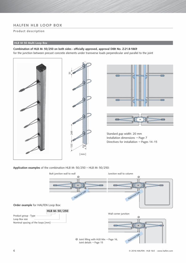
Combination of HLB M- 50/250 on both sides - offi cially approved, approval DIBt No. Z-21.8-1869for the junction between precast concrete elements under transverse loads perpendicular and parallel to the joint
Product description
Standard gap width: 20 mmInstallation dimensions → Page 7Directives for installation → Pages 14 - 15
HLB M 50 Multi Loop Box
Order example for HALFEN Loop Box:
Product group - TypeLoop Box sizeNominal spacing of the loops [mm]
Application examples of the combination HLB M- 50/250 + HLB M- 50/250:
Butt junction wall to wall
Wall corner junction
Junction wall to column
Joint filling with HLB Mix → Page 16, Joint details → Page 15
Approved DIBt
Approved DIBt
Approved DIBt
HLB M- 50 / 250

7
© 2016 HALFEN · HLB 16-E · www.halfen.com
HALFEN HLB LOOP BOXV
Rd,
II [
kN/m
]
VRd, [% of the values of Tab. 'B']
60.0
55.0
50.0
45.0
40.0
35.0
30.0
25.0
20.0
15.0
10.0
5.0
0.0
0.0 20.0 40.0 60.0 80.0 100.0 120.0
Product description, load capacity according to EC 2, application examples
Bar B 500 A, diam. 12 mmBar B 500 A, diam. 10 mmStirrup B 500 A, diam. 8 mm, anchoring according to EC2HLB M- 50
HLB M- 50 installation scheme with additional reinforcement
The official approval applies for construction elements under predominantly static loads. If imposed deformations due to e.g. temperature changes or outdoor weathering can not be excluded, the crack width of the junction has to be restricted to wk ≤ 0.3 mm. Transverse loads do not lead to an additional crack opening. The product is not designed for regular tension loads. To include the expansion forces arising in the joint, an exterior tensional force has to be taken into consideration according to DAfStb booklet 525, which is at least 1.5 times the shear force to be transferred perpendicularly over the joint. The official approval is to be observed.
Equation:VRd, II [kN/m] = – 0.45 · VRd, [%] + 45
Load capacity for applications according to EC 2 Minimum reinforcement, alignment
Design value of the transverse load capacity perpendicular to the joint (plane of the wall)VRd. [kN/m] (Table 'B')
Wall thickness [cm]
HLB M- 50/250 + HLB M- 50/250C30/37 C35/45 C40/50 C45/55
14 8.8 10.0 10.7 11.415 10.2 11.6 12.4 13.316 11.7 13.3 14.3 15.217 13.2 15.0 16.1 17.218 14.8 16.9 18.1 19.319 16.4 18.7 20.1 21.420 18.1 20.6 22.2 23.621 19.9 22.6 24.3 25.922 21.6 24.7 26.5 28.223 23.5 26.8 28.7 30.624 25.4 28.9 31.0 33.025 27.3 31.1 33.3 35.5
≥ 26 29.2 33.3 35.7 37.5
Interaction diagram of the design values of the transverse load capacities parallel and perpendicular to the joint
Design value of the transverse load capacity parallel to the joint (plane of the wall) VRd. II [kN/m]
Wall thickness [cm]
HLB M- 50/250 + HLB M- 50/250C30/37 C35/45 C40/50 C45/55
≥ 14 45.0 *
* Moreover, no further limitation of the absorbable shear stresses in the joint of diaphragms according to EC2, chapter 10.9.3 (12) is required.

8
[ mm ] [ mm ]
© 2016 HALFEN · HLB 16-E · www.halfen.com
HALFEN HLB LOOP BOX
Product description
Order examples for HALFEN Loop Box:
Combination of HLB M- 20/250 + HLB M-100/250 - offi cially approved, approval DIBt No. Z-21.8-1871for the junction between precast concrete elements under transverse loads perpendicular and parallel to the joint
HLB M 20 and HLB M 100 Multi Loop Box
T-shaped wall junction
Application examples of the combination HLB M- 20/250 + HLB M-100/250:
Butt junction wall to wall
Wall corner junction
Joint filling with HLB Mix → Page 16, Joint details → Page 15
Product group - TypeLoop Box sizeNominal spacing of the loops [mm]
Standard gap width: 20 mmInstallation dimensions → Page 9Directives for installation → Pages 14 - 15
Approved DIBt
Approved DIBt
Approved DIBtHLB M-100 / 250
HLB M- 20 / 250

9
© 2016 HALFEN · HLB 16-E · www.halfen.com
HALFEN HLB LOOP BOXV
Rd,
II [
kN/m
]
VRd. [% of the values of Tab. 'C' ]
60.0
50.0
40.0
30.0
20.0
10.0
0.0
0.0 20.0 40.0 60.0 80.0 100.0 120.0
Product description, load capacity according to EC 2, application examples
HLB M- 20/250 + HLB M-100/250 installation scheme with additional reinforcement
Bar B 500 A, diam. 12 mmBar B 500 A, diam. 10 mmStirrup B 500 A, diam. 8 mm, anchoring according to EC2HLB M- 20/250HLB M-100/250
Equation:VRd, II [kN/m] = – 0.5 · VRd, [%] + 50
Load capacity for applications according to EC 2 Minimum reinforcement, alignment
The official approval applies for construction elements under predominantly static loads. If imposed deformations due to e.g. temperature changes or outdoor weathering can not be excluded, the crack width of the junction has to be restricted to wk ≤ 0.3 mm. Transverse loads do not lead to an additional crack opening. The product is not designed for regular tension loads. To include the expansion forces arising in the joint, an exterior tensional force has to be taken into consideration according to DAfStb booklet 525, which is at least 1.5 times the shear force to be transferred perpendicularly over the joint. The official approval is to be observed.
Design value of the transverse load capacity parallel to the joint (plane of the wall)VRd. II [kN/m]
Wall thickness [cm]
HLB M- 20/250 + HLB M-100/250C30/37 C35/45 C40/50 C45/55
≥ 14 50.0 *
* Moreover, no further limitation of the absorbable shear stresses in the joint of diaphragms according to EC2, chapter 10.9.3 (12) is required.
Design value of the transverse load capacity perpendicular to the joint (plane of the wall)VRd. [kN/m] (Table 'C')
Wall thickness [cm]
HLB M- 20/250 + HLB M-100/250C30/37 C35/45 C40/50 C45/55
14 8.8 10.0 10.7 11.415 10.2 11.6 12.4 13.316 11.7 13.3 14.3 15.217 13.2 15.0 16.1 17.218 14.8 16.9 18.1 19.319 16.4 18.7 20.1 21.420 18.1 20.6 22.2 23.621 19.9 22.6 24.3 25.922 21.6 24.7 26.5 28.223 23.5 26.8 28.7 30.624 25.4 28.9 31.0 33.025 27.3 31.1 33.3 35.5
≥ 26 29.2 33.3 35.7 37.5
Interaction diagram of the design values of the transverse load capacities parallel and perpendicular to the joint
10
HLB S
[ mm ]
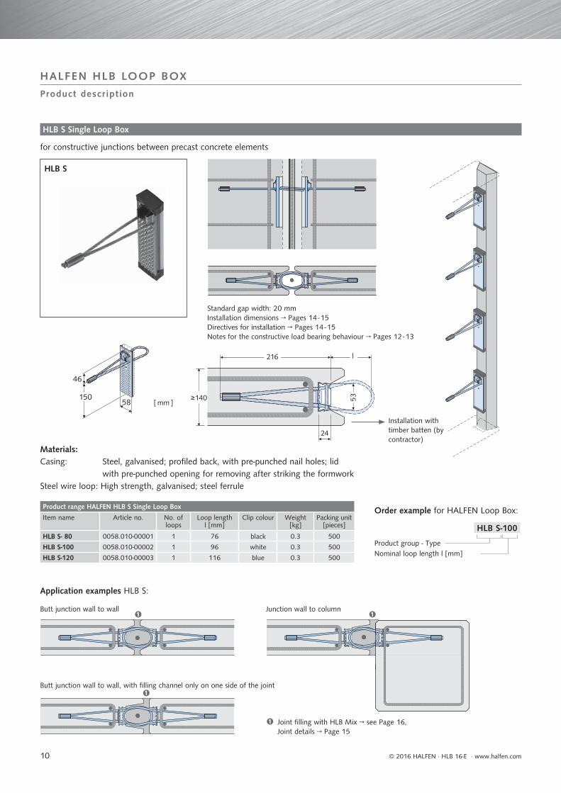
HLB S-100
© 2016 HALFEN · HLB 16-E · www.halfen.com
HALFEN HLB LOOP BOX
Product description
Order example for HALFEN Loop Box:
Product group - TypeNominal loop length l [mm]
HLB S Single Loop Box
Installation with timber batten (by contractor)
Application examples HLB S:
for constructive junctions between precast concrete elements
Materials:Casing: Steel, galvanised; profi led back, with pre-punched nail holes; lid
with pre-punched opening for removing after striking the formwork Steel wire loop: High strength, galvanised; steel ferrule
Joint filling with HLB Mix → see Page 16, Joint details → Page 15
Butt junction wall to wall
Butt junction wall to wall, with filling channel only on one side of the joint
Junction wall to column
Standard gap width: 20 mmInstallation dimensions → Pages 14 - 15Directives for installation → Pages 14 - 15Notes for the constructive load bearing behaviour → Pages 12 - 13
Product range HALFEN HLB S Single Loop Box
Item name Article no. No. of loops
Loop length l [mm]
Clip colour Weight [kg]
Packing unit [pieces]
HLB S- 80 0058.010-00001 1 76 black 0.3 500
HLB S-100 0058.010-00002 1 96 white 0.3 500
HLB S-120 0058.010-00003 1 116 blue 0.3 500

11
HLB Spacer- 20
HLB Loop Box
HLB SpacerHLB Spacer
HLB Loop Box
HLB Spacer- 50 HLB Spacer-100
HLB Spacer- 50
© 2016 HALFEN · HLB 16-E · www.halfen.com
HALFEN HLB LOOP BOX
Economical and time saving method for producing a continuous joint fi lling channel, which is requested, if HALFEN Multi Loop Box elements are applied with interspacing for length adaption.
Material: foam profi le strip, dimensionally stable
Application
Order example HLB Spacer:
Product group - Typefits to Loop Box HLB M size
HLB Spacer for Loop Box
Type range HALFEN HLB Spacer for Loop Box
Item name Article no. fits toLoop Box
Packing unit
[pieces]
Length[mm]
HLB Spacer- 20 0058.070-00001 HLB M- 20 80 1000
HLB Spacer- 50 0058.070-00002 HLB M- 50 60 1000
HLB Spacer-100 0058.070-00003 HLB M-100 40 1000
Application:
• Select the HLB Spacer type suitable to the Loop Box
• Cut to the required length using a common cutter or sharp knife
• Attach the HLB Spacer to the formwork using nails, glue or adhesive tape

12 © 2016 HALFEN · HLB 16-E · www.halfen.com
HALFEN HLB LOOP BOX
Information on the constructive load bearing behaviour
1. Transfer of tension loads perpendicular to the joint
2. Transfer of shear loads parallel to the joint
Fig. 2: Model for the tension load vertical to the joint
Fig. 4: Model for shear load parallel to the joint
plan viewplan view
D, ZD, Z
Fig. 1: Tension loads perpen-dicular to the joint
Fig. 3: Shear load parallel to the joint
The transfer of tension loads results from the overlap of the wire loops (fi g. 1). In the area of the loops the compression loads are transmitted to the grout fi ll. A tension load acts vertically to the plane of the loop, which must be taken up by a vertical reinforcement bar, as shown in fi g. 2.
Assuming a global safety factor = 3.0 and a minimum breaking load of the cable of Fmin = 22.7 kN the maximum applicable tension load Zmax,l is 15.1 kN per wire loop.
Considering the serviceability limit state we recommend to specify a load not exceeding 10 kN per loop (characteristic value). Experimental tests, which have been carried out with concrete grade C30/37 and a clearance between the HLB S elements of 11 cm in the longitudinal direction of the joint, resulted in a widening of the joint of 0.4 mm at this load.
B 500 Adiam. 12 mm
Note: for the offi cially approved product combinations refer to the information given in this brochure (→ Pages 6 - 9) and in the offi cial approval documents.
The following notes provide a basic understanding of the load bearing behaviour for the constructive application. However they are not to be considered as normative proofs.
Bar B 500 Adiam. 12 mm
Shear loads can act parallel to the joint (fi g. 3). A model for the transfer of these shear loads across the joint is shown in fi g. 4. Therein the shear load acting in the joint is divided into a tension and a compression strut. The values of the tension and compression loads depend on the angle .
HALFEN Single Loop Box: According to the model scheme shown in fi g. 4 a strut is formed between the recess boxes of the precast elements facing each other. The tension load is transferred to the overlapping cable loops.
Zmax,l = ——————Fmin · 2
= —————— = 15.1 kN
22.7 · 23.0

13© 2016 HALFEN · HLB 16-E · www.halfen.com
HALFEN HLB LOOP BOX
Information on the constructive load bearing behaviour
3. Transfer of shear loads perpendicular to the joint
Notes for fi re protection
Fig. 6: Model for shear load perpendicular to the joint
Fig. 5: Shear load perpendicular to the jointFor the transfer of shear loads perpendicular to the joint
(fi g. 5) the geometry of the joint is particularly important. It can be assumed, that between the concrete fl anks of the opposing precast elements a strut is formed according to fi g. 6. The tension load is transferred to the overlapping cable loops.
It is recommended to carry out the calculation in the same way as for unreinforced slab joints, wherein the geometry is to be considered.
Regarding the fi re protection the relevant regulations apply.
The cable loop of the HALFEN HLB Loop Box consists of a steel wire strength class 1770. It is commonly used in rein-forced concrete structures. Therefore the regulations for rein-forcement steel and for tensioning cables are to be observed.
In this connection the breaking stresses of the reinforcement steel and the cable loops at high temperatures have to be checked.
Furthermore, diff erent demands are made on the centre distances for reinforcement steel and for tensioning cables. The minimum dimensions for the centre distances and further details of the constructive design depend on the required fi re resistance class.
Bar B 500 Adiam. 12 mm

14 © 2016 HALFEN · HLB 16-E · www.halfen.com
HALFEN HLB LOOP BOX
Joint filling grout HLB Mix → Page 16
Joint for in-situ grout fi ll
Installation instructions
Construction details:
HLB Spacer, cut to length, see → Page 11
HLB Multi Loop Box
HLB Single Loop Box
HLB Multi Loop Box
HLB Multi Loop Box
Timber batten (by contractor)
HLB MMulti Loop Box:Continuous casing
HLB MMulti Loop Box:Continuous casing + interspace filled with HLB Spacer
HLB S Single Loop Boxsingle elements on timber batten
The joint for the in-situ grout fi ll has to be provided through-out the entire height of the concrete element. An adequate joint depth must be provided, depending on the length of the cable loop. It must be ensured that - the cable loops have a suffi cient overlapping and that - popped up loops have enough space without abutting.
After setting up the precast elements, a reinforcement bar (reinforcing steel B 500 A) diam. 12 mm must be inserted into the joint through the overlapping cable loops.For applications designed as constructive junction it is recom-mended to provide U-shaped stirrups (reinforcing steel grade B 500 A) diam. 8 mm, so that an overlap junction between the tail of the cable loops and the U-shaped stirrup is created as with the offi cially approved HLB Loop Boxes.
- Examples for HLB Loop Box applications designed as constructive junction:
- surface area reinforcement - centric area reinforcement - without area reinforcement
Reinforcement
Joint width
Joint filling channel Reinforcement bar
B 500 A, diam. 12 mm
U
HLB S: joint depth t, overlapping U [mm]at 20 mm gap width, HLB elements in pairsHLB S t U- 80 40 52-100 50 72-120 60 92
15
mm
© 2016 HALFEN · HLB 16-E · www.halfen.com
HALFEN HLB LOOP BOX
Installation instructions
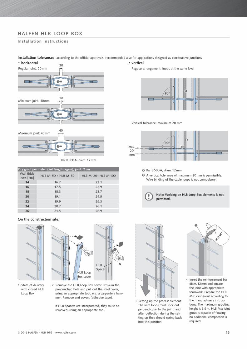
Regular joint: 20 mm Regular arrangement: loops at the same level
Vertical tolerance: maximum 20 mm
Minimum joint: 10 mm
Maximum joint: 40 mm
1. State of delivery with closed HLB Loop Box
2. Remove the HLB Loop Box cover: strike-in the pre-punched hole and pull out the steel cover, using an appropriate tool, e.g. a carpenters ham-mer. Remove end covers (adhesive tape).
If HLB Spacers are incorporated, they must be removed, using an appropriate tool.
Installation tolerances
On the construction site:
• horizontal • vertical
Bar B 500 A, diam. 12 mm
Bar B 500 A, diam. 12 mm
A vertical tolerance of maximum 20 mm is permissible. Wire binding of the cable loops is not compulsory.
HLB Loop Box cover
HLB Spacer
3. Setting up the precast element. The wire loops must stick out perpendicular to the joint, and after deflection during the set-ting up they should spring back into this position.
4. Insert the reinforcement bar diam. 12 mm and encase the joint with appropriate formwork. Prepare the HLB Mix joint grout according to the manufacturers instruc-tions. The maximum grouting height is 3.5 m. HLB Mix joint grout is capable of flowing, no additional compaction is required.
according to the official approvals, recommended also for applications designed as constructive junctions
Dry grout per meter joint length [kg/m]; joint: 2 cmWall thick-ness [cm]
HLB M- 50 + HLB M- 50 HLB M- 20+ HLB M-100
14 16.7 22.116 17.5 22.918 18.3 23.7
20 19.1 24.5
22 19.9 25.324 20.7 26.126 21.5 26.9
Note: Welding on HLB Loop Box elements is not permitted.
16
© 2016 HALFEN · HLB 16-E · www.halfen.com
HALFEN HLB LOOP BOX
In-situ joint grout filling
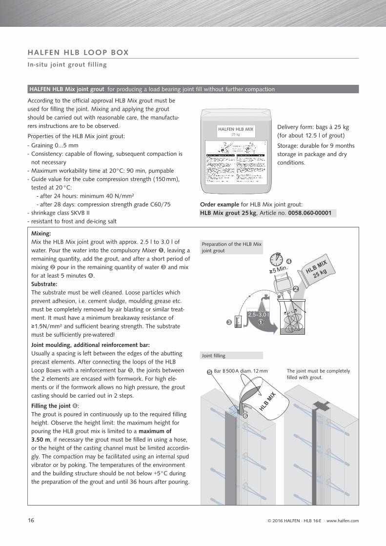
HALFEN HLB Mix joint grout
According to the offi cial approval HLB Mix grout must be used for fi lling the joint. Mixing and applying the grout should be carried out with reasonable care, the manufactu-rers instructions are to be observed.
Properties of the HLB Mix joint grout:
Mixing:Mix the HLB Mix joint grout with approx. 2.5 l to 3.0 l of water. Pour the water into the compulsory Mixer , leaving a remaining quantity, add the grout, and after a short period of mixing pour in the remaining quantity of water and mix for at least 5 minutes .Substrate:The substrate must be well cleaned. Loose particles which prevent adhesion, i.e. cement sludge, moulding grease etc. must be completely removed by air blasting or similar treat-ment. It must have a minimum breakaway resistance of ≥1.5N/mm² and suffi cient bearing strength. The substrate must be suffi ciently pre-watered!
Joint moulding, additional reinforcement bar:Usually a spacing is left between the edges of the abutting precast elements. After connecting the loops of the HLB Loop Boxes with a reinforcement bar , the joints between the 2 elements are encased with formwork. For high ele-ments or if the formwork allows no high pressure, the grout casting should be carried out in 2 steps.
Filling the joint : The grout is poured in continuously up to the required fi lling height. Observe the height limit: the maximum height for pouring the HLB grout mix is limited to a maximum of 3.50 m, if necessary the grout must be fi lled in using a hose, or the height of the casting channel must be limited accordin-gly. The compaction may be facilitated using an internal spud vibrator or by poking. The temperatures of the environment and the building structure should be not below +5°C during the preparation of the grout and until 36 hours after pouring.
Delivery form: bags à 25 kg (for about 12.5 l of grout)
Storage: durable for 9 months storage in package and dry conditions.
Preparation of the HLB Mix joint grout
Joint filling
Bar B 500 A diam. 12 mm The joint must be completely filled with grout.
- Graining 0…5 mm - Consistency: capable of fl owing, subsequent compaction is not necessary
- Maximum workability time at 20°C: 90 min, pumpable - Guide value for the cube compression strength (150 mm), tested at 20 °C: - after 24 hours: minimum 40 N/mm² - after 28 days: compression strength grade C60/75
- shrinkage class SKVB II - resistant to frost and de-icing salt
Order example for HLB Mix joint grout:HLB Mix grout 25 kg, Article no. 0058.060-00001
for producing a load bearing joint fi ll without further compaction
17
HLB M- 20
HLB Spacer- 20HLB Spacer- 50HLB Spacer-100HLB S HLB M- 50 HLB M-100
© 2016 HALFEN · HLB 16-E · www.halfen.com
HALFEN HLB LOOP BOX
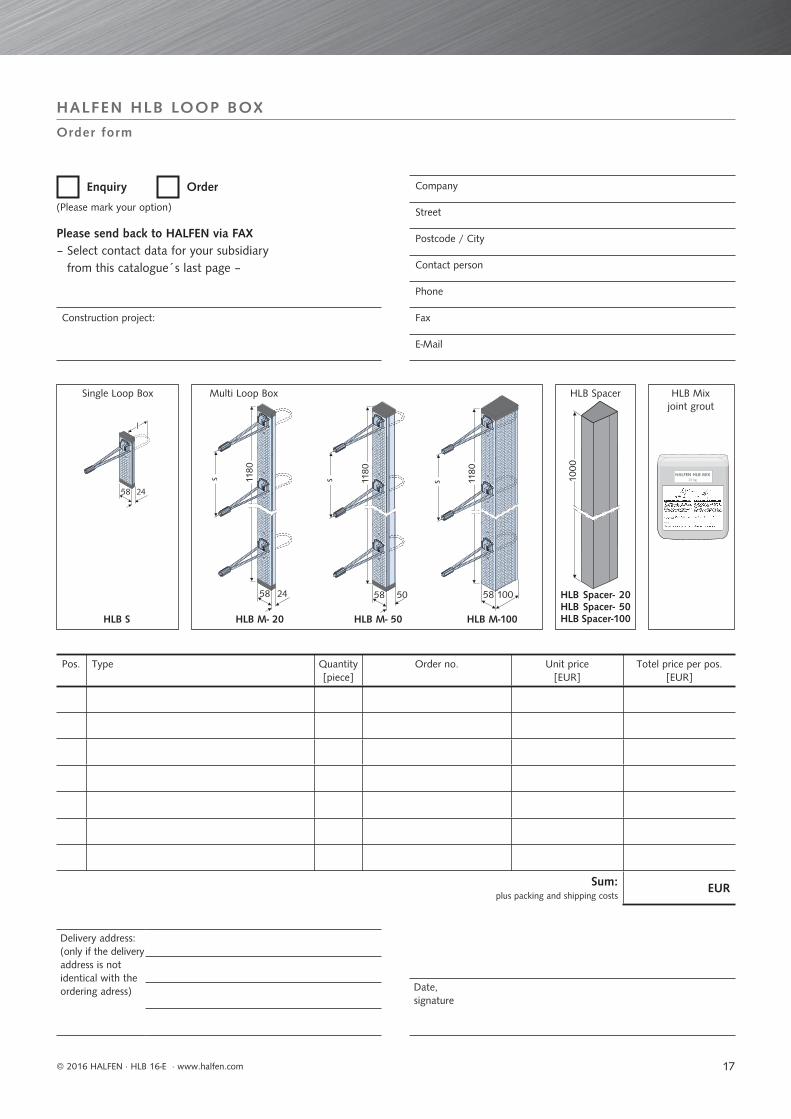
Order form
Enquiry Order
(Please mark your option)
Company
Street
Postcode / City
Contact person
Phone
Fax
Pos. Type Quantity[piece]
Order no. Unit price[EUR]
Totel price per pos.[EUR]
Sum:plus packing and shipping costs
EUR
Construction project:
Delivery address: (only if the delivery address is not identical with the ordering adress) Date,
signature
Single Loop Boxjoint grout
Multi Loop Box HLB Spacer HLB Mix
Please send back to HALFEN via FAX– Select contact data for your subsidiary
from this catalogue´s last page –

18 © 2016 HALFEN · HLB 16-E · www.halfen.com
HALFEN HLB LOOP BOX
Notes
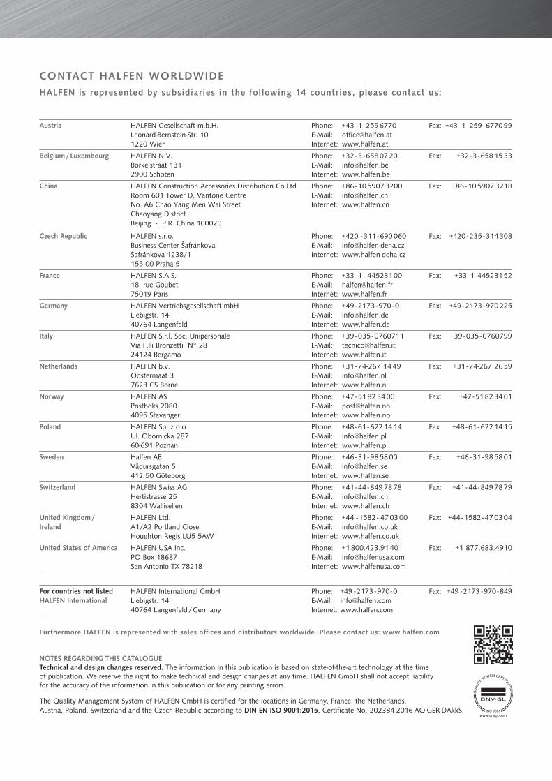
Austria HALFEN Gesellschaft m.b.H.Leonard-Bernstein-Str. 101220 Wien
Phone: +43 - 1 - 259 6770 E-Mail: [email protected]: www.halfen.at
Fax: +43 - 1 - 259 - 6770 99
Belgium / Luxembourg HALFEN N.V.Borkelstraat 1312900 Schoten
Phone: +32 - 3 - 658 07 20E-Mail: [email protected]: www.halfen.be
Fax: +32 - 3 - 658 15 33
China HALFEN Construction Accessories Distribution Co.Ltd.Room 601 Tower D, Vantone CentreNo. A6 Chao Yang Men Wai StreetChaoyang District Beijing · P.R. China 100020
Phone: +86 - 10 5907 3200E-Mail: [email protected]: www.halfen.cn
Fax: +86 - 10 5907 3218
Czech Republic HALFEN s.r.o.Business Center ŠafránkovaŠafránkova 1238/1155 00 Praha 5
Phone: +420 - 311 - 690 060E-Mail: [email protected]: www.halfen-deha.cz
Fax: +420 - 235 - 314 308
France HALFEN S.A.S.18, rue Goubet75019 Paris
Phone: +33 - 1 - 445231 00E-Mail: [email protected]: www.halfen.fr
Fax: +33 - 1 - 445231 52
Germany HALFEN Vertriebsgesellschaft mbHLiebigstr. 14 40764 Langenfeld
Phone: +49 - 2173 - 970 - 0E-Mail: [email protected]: www.halfen.de
Fax: +49 - 2173 - 970 225
Italy HALFEN S.r.l. Soc. UnipersonaleVia F.lli Bronzetti N° 2824124 Bergamo
Phone: +39 - 035 - 0760711E-Mail: [email protected]: www.halfen.it
Fax: +39 - 035 - 0760799
Netherlands HALFEN b.v.Oostermaat 37623 CS Borne
Phone: +31 - 74-267 14 49E-Mail: [email protected]: www.halfen.nl
Fax: +31 - 74-267 26 59
Norway HALFEN ASPostboks 20804095 Stavanger
Phone: +47 - 51 82 34 00E-Mail: [email protected]: www.halfen.no
Fax: +47 - 51 82 34 01
Poland HALFEN Sp. z o.o.Ul. Obornicka 28760-691 Poznan
Phone: +48 - 61 - 622 14 14E-Mail: [email protected]: www.halfen.pl
Fax: +48 - 61 - 622 14 15
Sweden Halfen ABVädursgatan 5412 50 Göteborg
Phone: +46 - 31 - 98 58 00E-Mail: [email protected]: www.halfen.se
Fax: +46 - 31 - 98 58 01
Switzerland HALFEN Swiss AGHertistrasse 25 8304 Wallisellen
Phone: +41 - 44 - 849 78 78E-Mail: [email protected]: www.halfen.ch
Fax: +41 - 44 - 849 78 79
United Kingdom /Ireland
HALFEN Ltd.A1/A2 Portland CloseHoughton Regis LU5 5AW
Phone: +44 - 1582 - 47 03 00E-Mail: [email protected]: www.halfen.co.uk
Fax: +44 - 1582 - 47 03 04
United States of America HALFEN USA Inc. PO Box 18687 San Antonio TX 78218
Phone: +1 800.423.91 40E-Mail: [email protected]: www.halfenusa.com
Fax: +1 877.683.4910
For countries not listed HALFEN International
HALFEN International GmbHLiebigstr. 14 40764 Langenfeld / Germany
Phone: +49 - 2173 - 970 - 0 E-Mail: [email protected]: www.halfen.com
Fax: +49 - 2173 - 970 - 849
CONTACT HALFEN WORLDWIDEHALFEN is represented by subsidiaries in the following 14 countries, please contact us:
NOTES REGARDING THIS CATALOGUETechnical and design changes reserved. The information in this publication is based on state-of-the-art technology at the time of publication. We reserve the right to make technical and design changes at any time. HALFEN GmbH shall not accept liability for the accuracy of the information in this publication or for any printing errors.
The Quality Management System of HALFEN GmbH is certified for the locations in Germany, France, the Netherlands, Austria, Poland, Switzerland and the Czech Republic according to DIN EN ISO 9001:2015, Certificate No. 202384-2016-AQ-GER-DAkkS.
Furthermore HALFEN is represented with sales offi ces and distributors worldwide. Please contact us: www.halfen.com
www.dnvgl.com

For further information please contact: www.halfen.com
© 2
016
HA
LFEN
Gm
bH, G
erm
any
appl
ies
also
to
copy
ing
in e
xtra
cts.
R -
035
- E -
12/1
6 PD
F 1
2/16