halfen balcony connections hit - construnario.com · halfen balcony connections hit deha studrail...
TRANSCRIPT
HALFEN BALCONY CONNECTIONS HIT
CONCRETE
CONCRETE FACADE
HALFEN PRECAST PANEL ANCHORS
FACADE
LUTZ STONE SUPPORT SYSTEMS
STONE SUPPORT SYSTEMS
FACADE
FACADE
TENSION ROD SYSTEMSDEHA SLEEVE SANDWICH PANEL ANCHORS
FACADE
FACADE
FRAMING
FRAMING
FRAMING
CONCRETE
CONCRETE
CONCRETE
CONCRETE
CONCRETE
CONCRETE
CONCRETE
CONCRETE
CONCRETE
CONCRETE
CONCRETE
CONCRETE
CONCRETE
CONCRETE
FACADE
CONCRETE
FACADE
FACADE
CONCRETE
CONCRETE
CONCRETE
CONCRETE
CONCRETE
CONCRETE
CONCRETE
ANCHORING TECHNOLOGY
HALFEN CORNER GUARDS
HALFEN SHEAR BOLT ANCHORS
DEMU SOCKETS/INSERTS
HALFEN BALUSTRADE FIXINGS
HALFEN BRICK TIE CHANNELS
HALFEN HTU CAST IN CHANNELS
HALFEN CAST IN CHANNELS
HALFEN BRICK TIES
HALFEN BRICKWORK SUPPORT
BRICKWORK SUPPORT SYSTEMS
REINFORCEMENT TECHNOLOGY
CRET SHEAR LOAD CONNECTOR
HALFEN BALCONY CONNECTIONS HIT
DEHA STUDRAIL
HALFEN SHEAR REINFORCEMENT HDB
REINFORCEMENT COUPLERS MBT
HALFEN REBEND CONNECTION HBT
DEMU SCREW CONNECTION
SCREW CONNECTIONS WD 90
HALFEN SCREW CONNECTIONS HBS
DEHA REINFORCEMENT SPACERS
HALFEN WIRE SANDWICH PANEL ANCHORS
TRANSPORT ANCHORAGE SYSTEMS
HALFEN POWERCLICK
HALFEN FRAMING CONSTRUCTIONS
HALFEN FRAMING CHANNELS AND ACCESSORIES
DEHA LIFTING DEVICES
DEHA LIFTING LOOPS
DEHA SOCKET ANCHOR SYSTEM
DEHA TRANSPORT ANCHOR SYSTEM
FRIMEDA TRANSPORT ANCHOR SYSTEM
DETAN TENSION ROD SYSTEM
FRAMING SYSTEMS
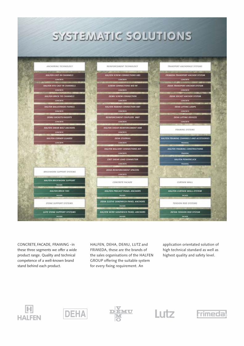
HALFEN, DEHA, DEMU, LUTZ andFRIMEDA, these are the brands ofthe sales organisations of the HALFENGROUP offering the suitable systemfor every fixing requirement. An
application orientated solution ofhigh technical standard as well ashighest quality and safety level.
CONCRETE,FACADE, FRAMING -inthese three segments we offer a wideproduct range. Quality and technicalcompetence of a well-known brandstand behind each product.
HALFEN CURTAIN WALL-SYSTEM
CURTAIN WALL
3
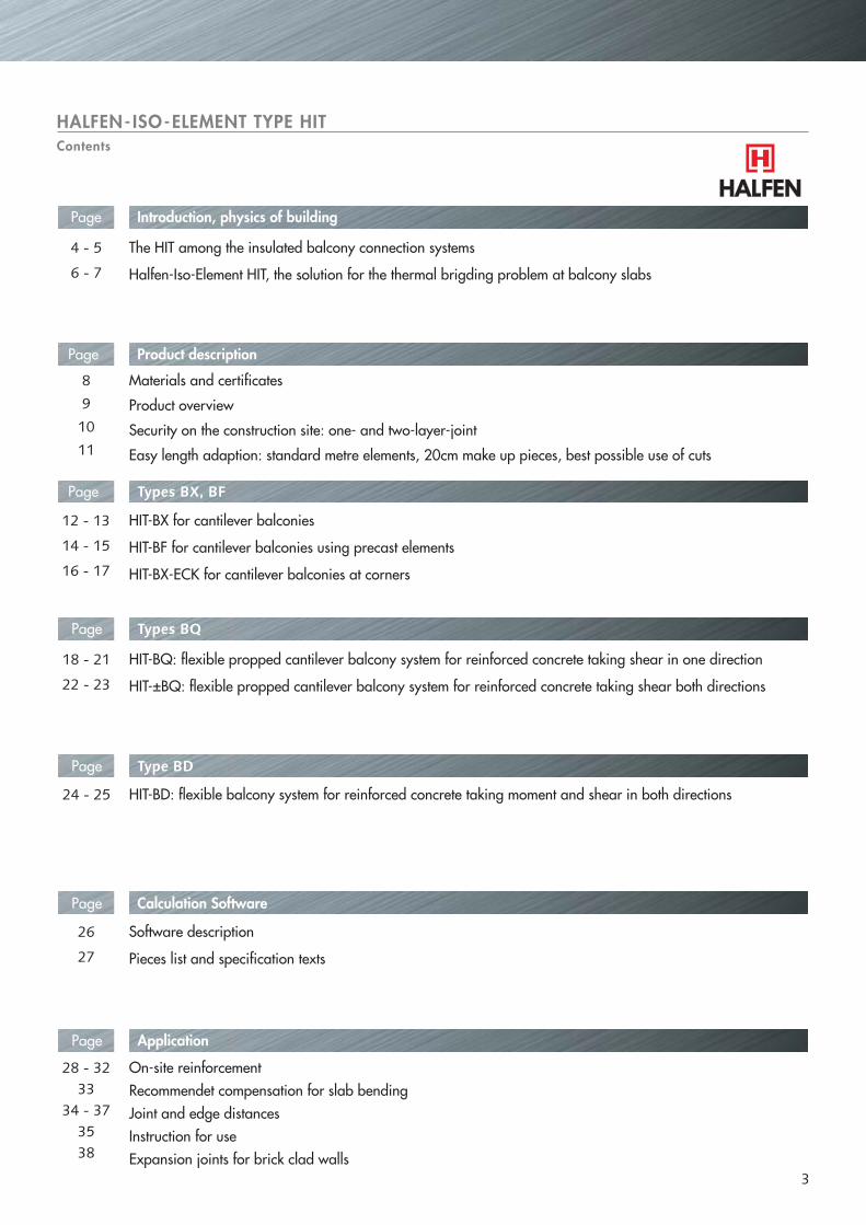
Introduction, physics of building
The HIT among the insulated balcony connection systems
Halfen-Iso-Element HIT, the solution for the thermal brigding problem at balcony slabs
Product descriptionPage
Materials and certificates
Product overview
Security on the construction site: one- and two-layer-joint
Easy length adaption: standard metre elements, 20cm make up pieces, best possible use of cuts
HIT-BX for cantilever balconies
HIT-BF for cantilever balconies using precast elements
HIT-BX-ECK for cantilever balconies at corners
Page
Page
HIT-BQ: flexible propped cantilever balcony system for reinforced concrete taking shear in one direction
HIT-±BQ: flexible propped cantilever balcony system for reinforced concrete taking shear both directions
Page
HIT-BD: flexible balcony system for reinforced concrete taking moment and shear in both directions
Calculation SoftwarePage
Software description
Pieces list and specification texts
ApplicationPage
On-site reinforcementRecommendet compensation for slab bendingJoint and edge distancesInstruction for useExpansion joints for brick clad walls
HALFEN- ISO-ELEMENT TYPE HITContents
Page
Types BX, BF
Types BQ
Type BD
4 - 5
6 - 7
8
9
10
11
12 - 13
14 - 15
16 - 17
18 - 21
22 - 23
24 - 25
26
27
28 - 32
3538
3334 - 37
HITHIT
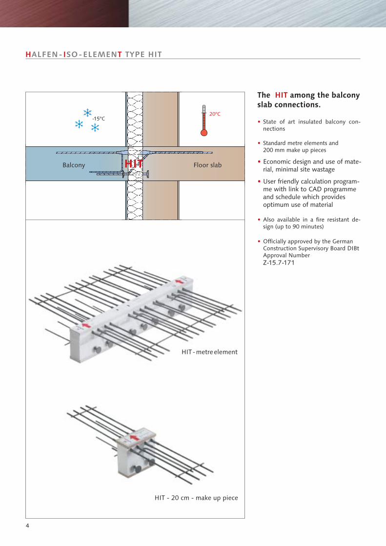
20°C-15°C
4
H I TALFEN- SO-ELEMEN TYPE HIT
• State of art insulated balcony con-nections
•
•
•
Standard metre elements and200 mm make up pieces
Economic design and use of mate-rial, minimal site wastage
User friendly calculation program-me with link to CAD programmeand schedule which providesoptimum use of material
• Also available in a fire resistant de-sign (up to 90 minutes)
• Officially approved by the GermanConstruction Supervisory Board DIBtApproval NumberZ-15.7-171
HIT-metreelement
HIT - 20 cm - make up piece
The among the balconyslab connections.
HIT
Balcony Floor slab
5
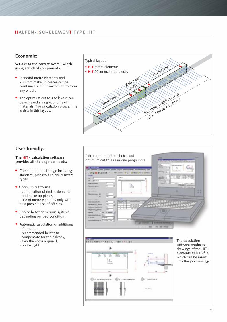
Calculation, product choice andoptimum cut to size in one programme.
The calculationsoftware producesdrawings of the HIT-elements as DXF-file,which can be insertinto the job drawings.
User friendly:
H I TALFEN- SO-ELEMEN TYPE HIT
1m-element
1m-element
1m-element
1m-element
•
•
•
•
Complete product range including:standard, precast- and fire resistanttypes.
Optimum cut to size:- combination of metre elements and make up pieces,- use of metre elements only withbest possible use of off cuts.
Choice between various systemsdepending on load condition.
Automatic calculation of additionalinformation- recommended height to compensate for the balcony,- slab thickness required,- unit weight.
Make up
pieceMake up
piece
Example: w
idth 2,20 m
( 2 × 1,00 m + 0,20 m)
Economic:
Set out to the correct overall widthusing standard components.
Typical layout:
metre elements20cm make up pieces
• HIT• HIT
•
•
Standard metre elements and200 mm make up pieces can becombined without restriction to formany width.
The optimum cut to size layout canbe achieved giving economy ofmaterials. The calculation programmeassists in this layout.
Make up
piece
The - calculation softwareprovides all the engineer needs:
HIT
6
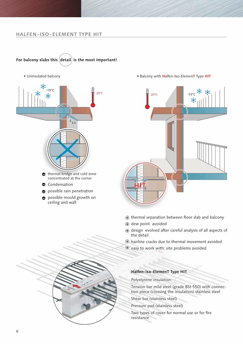
20°C -15°C20°C-15°C
HALFEN-ISO-ELEMENT TYPE HIT
thermal bridge and cold zoneconcentrated at the corner
Condensation
possible rain penetration
possible mould growth onceiling and wall
• Uninsulated balcony
For balcony slabs this detail is the most important!
thermal separation between floor slab and balcony
dew point avoided
design evolved after careful analysis of all aspects ofthe detail
hairline cracks due to thermal movement avoided
easy to work with: site problems avoided
Polystyrene insulation
Tension bar mild steel (grade BSt 550) with connec-tion piece (crossing the insulation) stainless steel
Shear bar (stainless steel)
Pressure pad (stainless steel)
Two types of cover for normal use or for fireresistance
Halfen-Iso-ElemenT Type HIT
• Balcony with alfen- so-Elemen TypeH I T HIT
–
–
––
7
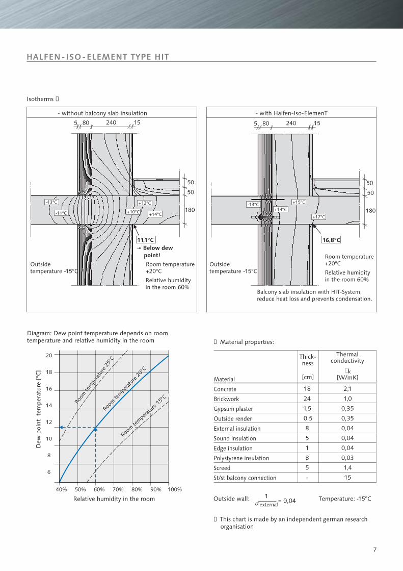
16,8°C
+14°C
+15°C
+17°C
80 152405
50
180
50
-13°C-13°C
-11°C +10°C
+12°C
+14°C
80 152405
50
180
50
11,1°C
20
18
16
14
12
10
8
6
40% 50% 60% 70% 80% 90% 100%
HALFEN-ISO-ELEMENT TYPE HIT
Raum
luftt
empe
ratu
r 20°
C
Room
tem
pera
ture
25°C
Raumluf
ttempe
ratur
20°C
Raumluf
ttempe
ratur
20°C
Room
tem
pera
ture
20°C
Room
tem
pera
ture
25°C
Room te
mperat
ure 1
5°C
Diagram: Dew point temperature depends on roomtemperature and relative humidity in the room
Relative humidity in the room
Dew
poi
nt t
empe
ratu
re [
°C]
Temperature:
➀ Material properties:
➀ This chart is made by an independent german researchorganisation
Outside wall:
Thermalconductivity
Thick-ness
Room temperature+20°C
Outsidetemperature -15°C
Outsidetemperature -15°C
Room temperature+20°C
Balcony slab insulation with HIT-System,reduce heat loss and prevents condensation.
→ Below dewpoint!
Isotherms ➀
- without balcony slab insulation - with Halfen-Iso-ElemenT
Relative humidityin the room 60%
Relative humidityin the room 60%
Material
Concrete
Brickwork
Gypsum plaster
Outside render
External insulation
Sound insulation
Edge insulation
Polystyrene insulation
Screed
St/st balcony connection
1αexternal
-15°C
[W/mK]� k
[cm]
–––––– = 0,04
18
24
1,5
0,5
8
5
1
8
5
-
2,1
1,0
0,35
0,35
0,04
0,04
0,04
0,03
1,4
15
8
�
�
�
�
�
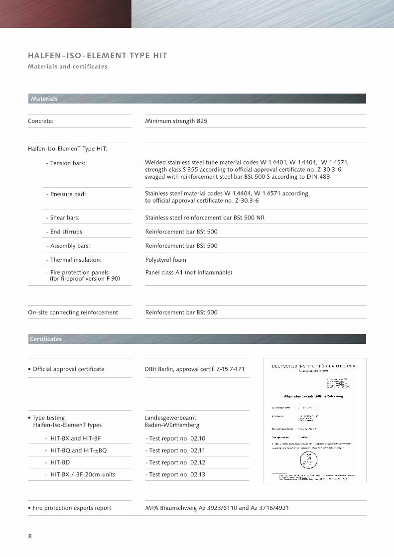
HALFEN-ISO-ELEMENT TYPE HIT
Materials
Certificates
Concrete: Minimum strength B25
Halfen-Iso-ElemenT Type HIT:
- Tension bars:
- Pressure pad:
- Shear bars:
- End stirrups:
- Assembly bars:
- Thermal insulation:
Stainless steel reinforcement bar BSt 500 NR
R BSt 500einforcement bar
Reinforcement bar BSt 500
Polystyrol foam
Reinforcement bar BSt 500
- Fire protection panels(for fireproof version F 90)
Panel class A1 (not inflammable)
Welded stainless steel tube material codes W 1.4401, W 1.4571,strength class S 355 according to official approval certificate no. Z-30.3-6,swaged with reinforcement steel bar BSt 500 S according to DIN 488
W 1.4404,
Stainless steel material codes W 1.4571 accordingto official approval certificate no. Z-30.3-6
W 1.4404,
On-site connecting reinforcement
• Official approval certificate DIBt Berlin, approval certif. Z-15.7-171
• Type testingHalfen-Iso-ElemenT types
LandesgewerbeamtBaden-Württemberg
- HIT- and HIT-BFBX
- HIT-BQ and HIT-±BQ
- HIT-BD
- HIT-BX-/-BF-20cm-units
- Test report no. 02.10
- Test report no. 02.11
- Test report no. 02.12
- Test report no. 02.13
• Fire protection experts report MPA Braunschweig Az 3923/6110 and Az 3716/4921
Materials and certificates
9
Materials
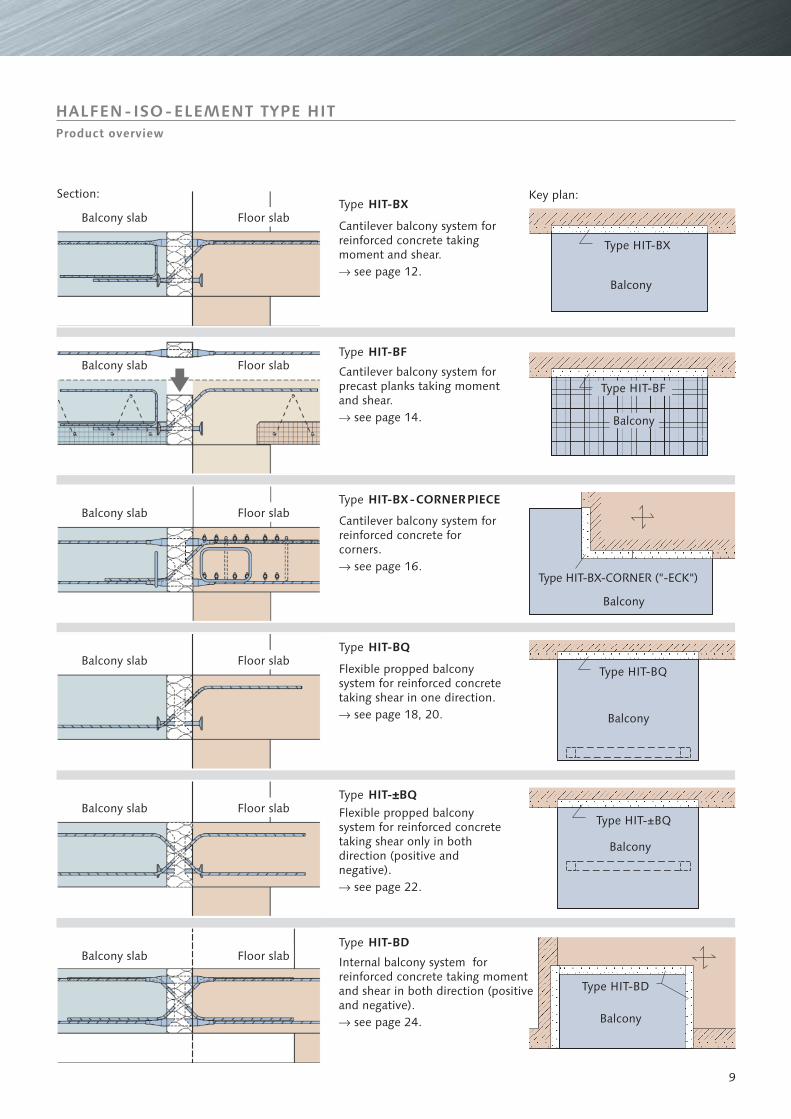
Product overview
Type HIT-BX
Type HIT-BQ
Type HIT-BD
Type HIT- BQ±
Type HIT-BX-CORNER ("-ECK")
Type HIT-BF
Balcony
Balcony
Balcony
Balcony
Balcony
Balcony
Type HIT-BX
Cantilever balcony system forreinforced concrete takingmoment and shear.� see page 12.
Cantilever balcony system forprecast planks taking momentand shear.� see page 14.
Cantilever balcony system forreinforced concrete forcorners.� see page 16.
Flexible propped balconysystem for reinforced concretetaking shear in one direction.� see page 18, 20.
Flexible propped balconysystem for reinforced concretetaking shear only in bothdirection (positive andnegative).
see page 22.�
Internal balcony system forreinforced concrete taking momentand shear in both direction (positiveand negative).� see page 24.
Type HIT-BF
Type HIT-BX-CORNERPIECE
Type HIT-BQ
Type HIT-±BQ
Type HIT-BD
Balcony slab
Balcony slab
Balcony slab
Balcony slab
Balcony slab
Balcony slab
Floor slab
Floor slab
Floor slab
Floor slab
Floor slab
Floor slab
Section: Key plan:
HALFEN-ISO-ELEMENT TYPE HIT
10
��
�
��
� �
� �
� �� �
lü lü
�
�
�
�
�
��
605 60580
1290
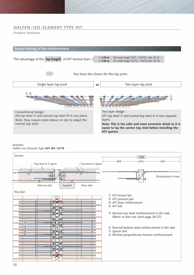
HALFEN-ISO-ELEMENT TYPE HITProduct Features
Example:Halfen-Iso-Element Type HIT-BX-12/10
Floor slabSupportBalcony slab
Key plan
Section
Top steel in 2 layers Top steel in 2 layers
Floo
r sl
ab
Secure setting of the reinforcement
The advantage of the of HIT tension bars:lap length for load range 10/7 - 12/10,for load range 12/12 - 14/12,
• 1,29 m• 1,48 m
bar- Ø 8bar- Ø 10
You have the choice for the lap joint:
Single layer lap joint
Conventional design:Hit top steel and normal top steel in one plane.Note: May require extra labour on site to adapt thenormal top steel.
� �
Two layer design:HIT top steel and normal top steel in two separatelayers.
� �
Note: This is the safer and more economic detail as it iseasier to lay the correct top steel before installing theHIT system.
or Two layer lap joint
Normal top steel reinforcement in the slab(fabric or bars see chart page 26-27)
HIT tension barHIT pressure padHIT shear reinforcementHIT link
Normal bottom steel reinforcement in the slabSpacer linkNormal perpendicular tension reinforcement
Dimensions in mm
Bal
cony
sla
b
�
�
�
�
�
�
�
�

11
2,10
2,30
2,50
2,70
2,90
1,00
Mo
Mo
Mo
Mo
Mo
Mo
Mo Mo
MoMo
Mo
Mo
Mo
Metre element
Metre element
Metre element
Metre element
Make up
pieceMake up
piece
Make up
pieceMake up
piece
Filler
pieceFiller
piece
Metre element
Metre element
Metre element
Metre element
Metre element
Metre element
Metre element
50 cm piece
for furth
er use
Cut remain
s
HALFEN-ISO-ELEMENT TYPE HITProduct features
Metre element
Metre element
Metre element
Example: Length 2,20 m
( 2 × 1,00 m + 0,20 m)
Example: Length 2,30 m
( 2 × 1,00 m + 0,20 m + 2 × 0,05 m)
Example: Length 2,00 m
( 2 × 1,00 m)
Make up
piece
Make up
piece
Filler
piece
Filler
piece
Metre element
Metre element
Metre element
Metre element
Metre elementExam
ple: Length 2,50 m
( 2 × 1,00 m + 0,50 m)
50 cm off c
ut
Metre element
Modular lengths and optimum cut to size
Standard metre elements and 200 mmmake up pieces can be combinedwithout restrictions to formany length. Adapted toany modular lengthusing polystyrenefiller pieces ifnecessary.
Optimum cut to size fromHIT metre elements
Metre element
Metre element
Metre element
Metre element
Metre element
Metre element
Metre element
Metre element
Metre element
Metre element
Length of balcony slab
• Diagram showing the balcony length achieved using metreelements, make up pieces and filler pieces
Metre element
Metre element
Metre element Metre element
Metre element
Metre element
Metre element
Metre element
Metre element
Metre element
Metre element
Metre element
Metre element
Metre element
Metre element
Metre element
Length of balcony slab
• Diagram showing the balcony length achievedusing modular length and site cuts.
Note:The arrangement of site cut elements must be checkedusing the calculation programme.
If you use filler pieces the calculation programme reducesthe load capacity automatically. Consider , see below.
HIT-element cut to length in accordance with officialapproval certificate.
➀➁
= HIT make up pieces (20 cm)
➀ To be checked in accordance with official approv. certificate:- max spacing of reinforcement bars: 30 cm;- min./max. distance of reinforcement from edge ormovement joint: 5 cm/15 cm.
Metre element
Metre element Metre element
Metre element 0,5 El.
Mo
Metre element
Metre element
Types= Filler, length 5 cm or less
Types HIT-FK-5HIT-FK-5-F90
HIT-. . -MOD,HIT-. . -MOD-F90
2,00
2,10
2,20
2,30
2,40
2,50
2,60
2,70
2,80
2,90
3,00
[m]
2,00
2,50
3,00
[m]
12
HIT-BX HIT
-BX
-ECK
d 1
8 cm
HIT-BX
HIT
-BQ
HIT
-BQ
HIT-BX
HIT
-BX
HIT-BX
BB
BB
2. layer
2. la
yer
Balcony
balcony
HIT-BX-20cm-makeuppiece
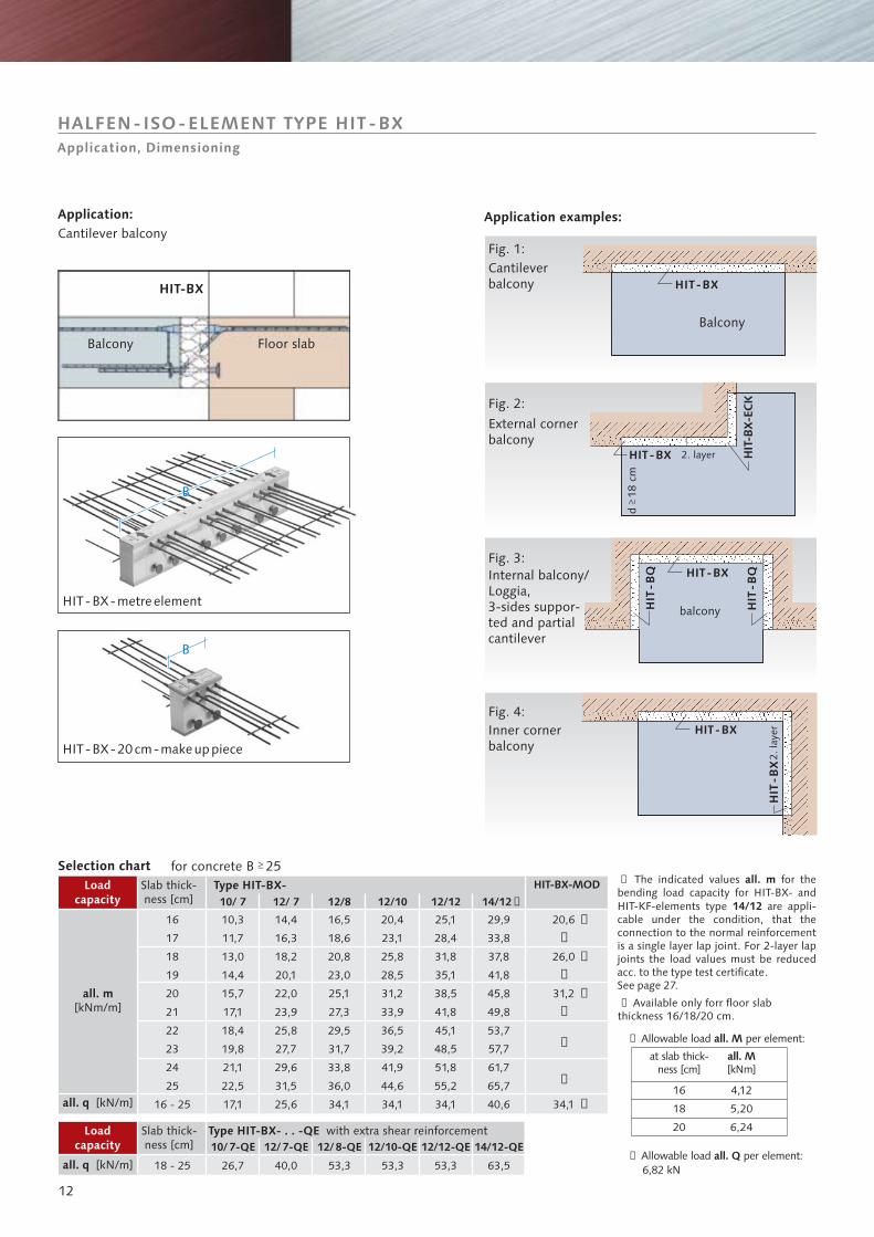
Application:Cantilever balcony
Application examples:
Cantileverbalcony
Fig. 1:
Fig. 2:
Fig. 3:
Fig. 4:
Internal balcony/Loggia,3-sides suppor-ted and partialcantilever
External cornerbalcony
Inner cornerbalcony
Selection chartSlab thick-ness [cm]
Slab thick-ness [cm]
Loadcapacity
for concrete B 25
Loadcapacity
all. m[kNm/m]
all. q [kN/m]
all. q [kN/m]
HIT-BX-metreelement
Type HIT-BX-
Type HIT-BX- . . -QE with extra shear reinforcement
Balcony Floor slab
HIT-BX
HALFEN-ISO-ELEMENT TYPE HIT-BXApplication, Dimensioning
all. m
14/12
➀ The indicated values for thebending load capacity for HIT-BX- andHIT-KF-elements type are appli-cable under the condition, that theconnection to the normal reinforcementis a single layer lap joint. For 2-layer lapjoints the load values must be reducedacc. to the type test certificate.See page 27.
➁ Available only forr floor slabthickness 16/18/20 cm.
➂ Allowable load per element:all. M
at slab thick-ness [cm]
all. M[kNm]
➃ Allowable load per element:6,82 kN
all. Q
➁
➁
➁
➁
➁
HIT-BX-MOD
20,6
26,0
31,2
34,1
10/ 7
10/7-QE
12/ 7
12/7-QE 12/10-QE
12/10
14/12-QE
14/1212/12
16
17
18
19
20
21
22
23
24
25
16 - 25
18 - 25
10,3
11,7
13,0
14,4
15,7
17,1
18,4
19,8
21,1
22,5
17,1
26,7
14,4
16,3
18,2
20,1
22,0
23,9
25,8
27,7
29,6
31,5
25,6
40,0 53,3
20,4
23,1
25,8
28,5
31,2
33,9
36,5
39,2
41,9
44,6
34,1
29,9
33,8
37,8
41,8
45,8
49,8
53,7
57,7
61,7
65,7
40,6
25,1
28,4
31,8
35,1
38,5
41,8
45,1
48,5
51,8
55,2
34,1
63,553,3
12/8-QE 12/12-QE
12/8
53,3
16,5
18,6
20,8
23,0
25,1
27,3
29,5
31,7
33,8
36,0
34,1
➂
➂
➂
➃16
18
20
4,12
5,20
6,24
➀
13
160
-250 30
50
➃
➀
➁
➂
Z
D
z
30 50
80
50
50
180
-250
➃
➀
➁
➂
30 50
Z
D
z
80
Load range
• 2L (increased top cover)
Order example:
Order examplemake up piece:
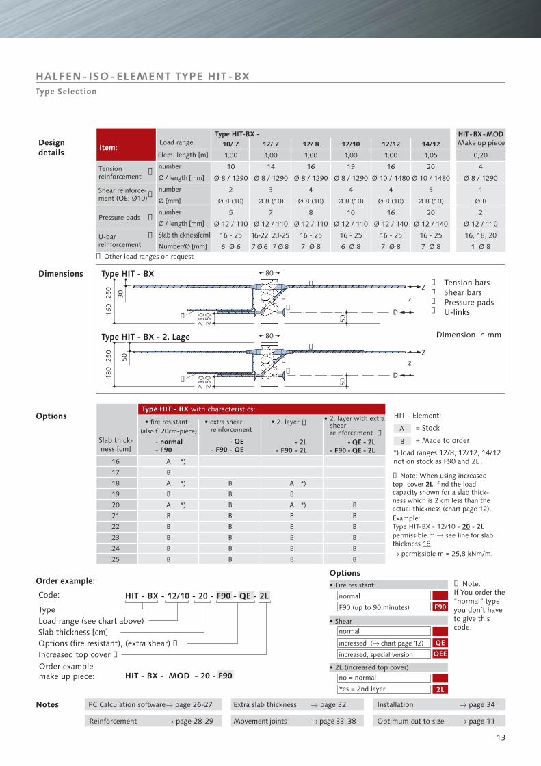
➄ Note:If You order the“normal” typeyou don´t haveto give thiscode.
Options• Fire resistant
• Shearnormal
chart page 12�increased ( )
increased, special version
no = normal
Yes = 2nd layer
normal
F90 (up to 90 minutes)
Notes PC Calculation software page 26-27�
Movement joints page 33, 38�Reinforcement page 28-29�
Installation page 34�Extra slab thickness page 32�
Optimum cut to size page 11�
Code:
• fire resistant(also f. 20cm-piece)
• extra shearreinforcement
• 2. layer • 2. layer with extrashearreinforcement
➅ Note: When using increasedtop cover , find the loadcapacity shown for a slab thick-ness which is
.Example:Type HIT-BX - 12/10 - -permissible m see line for slabthickness
2L
2L
2 cm less than theactual thickness (chart page 12)
permissible m = 25,8 kNm/m.
20�
�
18
Designdetails
Item:Elem. length [m]
Type HIT - BX
Type HIT - BX - 2. Lage
Tension barsShear barsPressure padsU-links
Dimension in mm
Type HIT-BX -Make up piece
number
n
Ø / length [mm]
umber
Ø [mm]
number
Ø / length [mm]
Slab thickness[cm]
Number/Ø [mm]
Tensionreinforcement
Shear reinforce-ment (QE: Ø10)
U-barreinforcement
Slab thick-ness [cm]
Type HIT - BX with characteristics:Options
Dimensions
HALFEN-ISO-ELEMENT TYPE HIT-BXType Selection
= Stock
= Made to order
*) load rangesas F90 and 2L .12/8, 12/12, 14/12
not on stock
HIT - Element:
Pressure pads
Other load ranges on request
TypeLoad range (see chart above)Slab thickness [cm]Options (fire resistant), (extra shear)Increased top cover
➃
➄
➀
➁
➂
➃
➀
➁
➂
➃
10/ 7 12/ 7 12/10 14/12HIT-BX-MOD
1,00
10
Ø 8 / 1290
2
Ø 8
5
16 - 25
6 Ø 6
(10)
Ø 12 / 110
0,20
4
1
Ø 8
2
16, 18, 20
1 Ø 8
Ø 8 / 1290
Ø 12 / 110
1,00
14
Ø 8 / 1290
3
Ø 8 (10)
7
Ø 12 / 110
16-22
7 Ø 6
23-25
7 Ø 8
1,00
19
Ø 8 / 1290
4
Ø 8 (10)
10
Ø 12 / 110
16 - 25
6 Ø 8
1,05
20
Ø 10 / 1480
5
Ø 8 (10)
20
Ø 12 / 140
16 - 25
7 Ø 8
A
*)
*)
*)
*)
*)
B
F90
QE
QEE
2L
HIT - BX - 12/10 - 20 - F90 - QE - 2L
HIT - BX - MOD - 20 - F90
- normal- F90
- QE - 2L- F90 - QE - 2L
- QE- F90 - QE
- 2L- F90 - 2L
16
17
18
19
20
21
22
23
24
25
A
B
A
B
A
B
B
B
B
B
B
B
B
B
B
B
B
B
A
B
A
B
B
B
B
B
➅
➅
B
B
B
B
B
B
12/ 8
1,00
16
4
Ø 8
8
16 - 25
7 Ø 8
Ø 8 / 1290
(10)
Ø 12 / 110
12/12
1,00
16
Ø 10 / 1480
4
Ø 8 (10)
16
Ø 12 / 140
16 - 25
7 Ø 8➆
14
HIT-BF
HIT-BF
HIT
-BQ
HIT
-BQ
BB
BB
HIT-BF
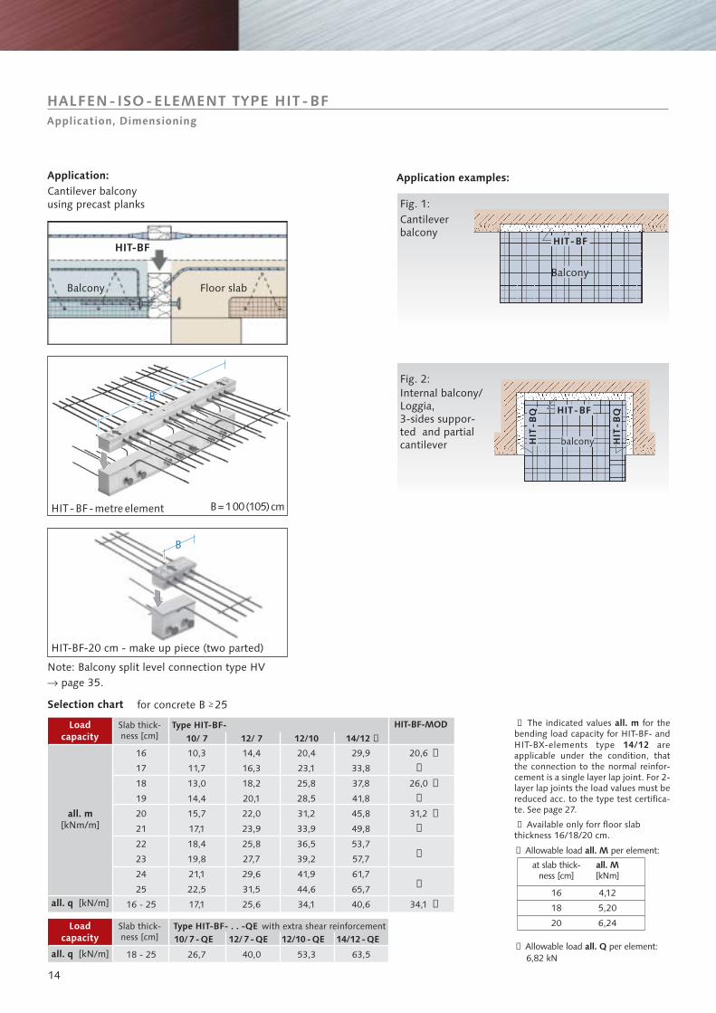
Note: Balcony connection type HVpage 35.
split level�
HALFEN-ISO-ELEMENT TYPE HIT-BFApplication, Dimensioning
all. m
14/12
➀ The indicated values for thebending load capacity for HIT-BF- andHIT-BX-elements type areapplicable under the condition, thatthe connection to the normal reinfor-cement is a single layer lap joint. For 2-layer lap joints the load values must bereduced acc. to the type test certifica-te. See page 27.
➁ Available only forr floor slabthickness 16/18/20 cm.
Balcony
balcony
HIT-BF-20 cm - make up piece (two parted)
Application:Cantilever balconyusing precast planks
Application examples:
Cantileverbalcony
Fig. 1:
Fig. 2:Internal balcony/Loggia,3-sides suppor-ted and partialcantilever
Selection chart
Slab thick-ness [cm]
Slab thick-ness [cm]
Loadcapacity
for concrete B 25
Loadcapacity
all. m[kNm/m]
all. q [kN/m]
all. q [kN/m]
HIT-BF-metreelement
Type HIT-BF-
Type HIT-BF- . . -QE with extra shear reinforcement
Balcony Floor slab
➂ Allowable load per element:all. M
at slab thick-ness [cm]
all. M[kNm]
➃ Allowable load per element:6,82 kN
all. Q
B=100(105)cm
➁
➁
➁
➁
➁
20,6
26,0
31,2
34,1
➂
➂
➂
➃16
18
20
4,12
5,20
6,24
HIT-BF-MOD
10/ 7
10/7 -QE
12/ 7
12/7 -QE 12/10- QE
12/10
14/12 - QE
14/12
16
17
18
19
20
21
22
23
24
25
16 - 25
18 - 25
10,3
11,7
13,0
14,4
15,7
17,1
18,4
19,8
21,1
22,5
17,1
26,7
14,4
16,3
18,2
20,1
22,0
23,9
25,8
27,7
29,6
31,5
25,6
40,0 53,3
20,4
23,1
25,8
28,5
31,2
33,9
36,5
39,2
41,9
44,6
34,1
29,9
33,8
37,8
41,8
45,8
49,8
53,7
57,7
61,7
65,7
40,6
63,5
➀
15
160
-250 30
50
�
�
�
�
Z
D
z
30 50
80
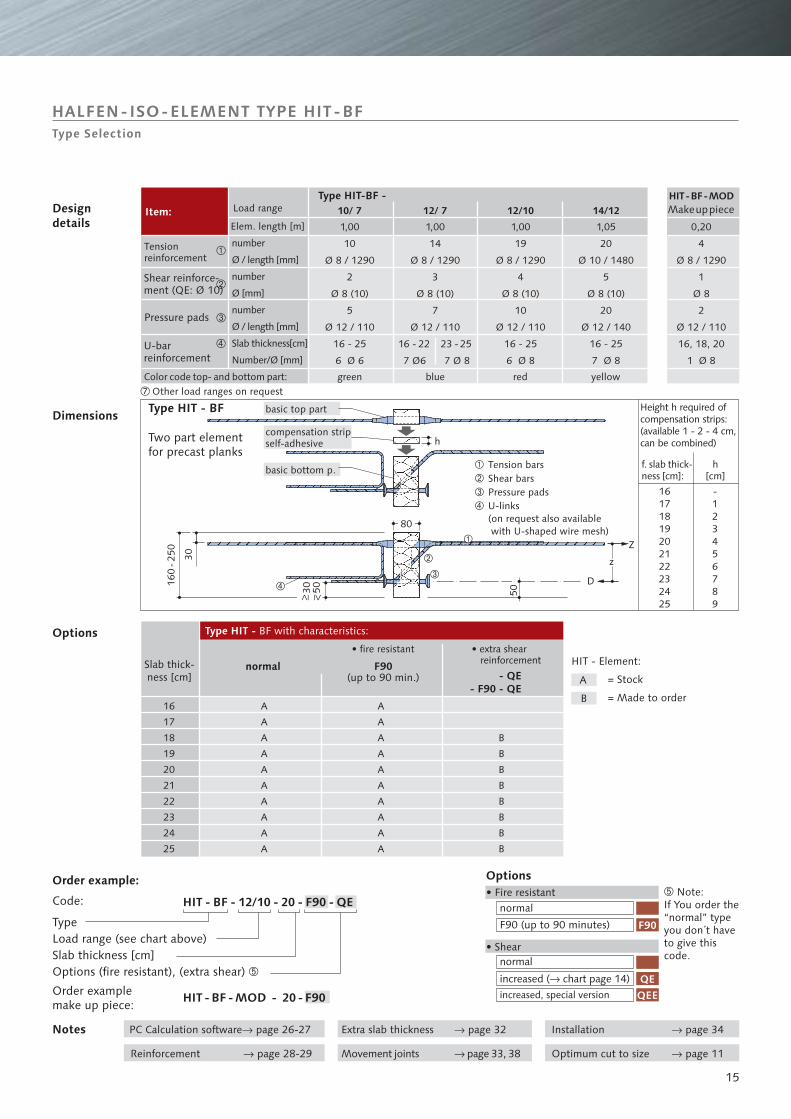
h
f. slab thick-ness [cm]:
Height h required ofcompensation strips:(available 1 - 2 - 4 cm,can be combined)
basic top part
compensation stripself-adhesive
basic bottom p.
green blue red yellowColor code top- and bottom part:
F90(up to 90 min.)
normal
Two part elementfor precast planks
HALFEN-ISO-ELEMENT TYPE HIT-BFType Selection
Order example:
Order examplemake up piece:
� Note:If You order the“normal” typeyou don´t haveto give thiscode.
Options• Fire resistant
• Shearnormal
chart page 14�
increased, special version
increased ( )
normal
F90 (up to 90 minutes)
Notes PC Calculation s �oftware page 26-27
Movement joints page 33, 38�Reinforcement page 28-29�
Installation page 34�Extra slab thickness page 32�
Optimum cut to size page 11�
Code:
TypeLoad range (see chart above)Slab thickness [cm]Options (fire resistant), (extra shear) �
• fire resistant • extra shearreinforcement
Designdetails
Item:Elem. length [m]
Type HIT - BF
Type HIT-BF -Makeuppiece
number
Ø / length [mm]
number
Ø [mm]
number
Ø / length [mm]
Slab thickness[cm]
Number/Ø [mm]
Tensionreinforcement
Shear reinforce-ment (QE: Ø 10)
U-barreinforcement
Slab thick-ness [cm]
Type HIT - BF with characteristics:Options
Dimensions
= Stock
= Made to order
HIT - Element:
Pressure pads
Load range
Other load ranges on request
Tension barsShear barsPressure padsU-links(on request also availablewith U-shaped wire mesh)
h[cm]
�
�
�
�
10/ 7 12/ 7 12/10 14/12HIT-BF-MOD
1,00
10
Ø 8 / 1290
2
Ø 8 (10)
5
Ø 12 / 110
16 - 25
6 Ø 6
0,20
4
Ø 8 / 1290
1
Ø 8
2
Ø 12 / 110
16, 18, 20
1 Ø 8
1,00
14
Ø 8 / 1290
3
Ø 8 (10)
7
Ø 12 / 110
16 - 22
7 Ø6
23 - 25
7 Ø 8
1,00
19
Ø 8 / 1290
4
Ø 8 (10)
10
Ø 12 / 110
16 - 25
6 Ø 8
1,05
20
Ø 10 / 1480
5
Ø 8 (10)
20
Ø 12 / 140
16 - 25
7 Ø 8
HIT - BF - MOD - 20 - F90
HIT - BF - 12/10 - 20 - F90 - QE
- QE- F90 - QE
16
17
18
19
20
21
22
23
24
25
A
B
F90
QEQEE
B
B
B
B
B
B
B
B
-123456789
16171819202122232425
A
A
A
A
A
A
A
A
A
A
A
A
A
A
A
A
A
A
A
A
�
�
�
�
�
16
HIT-BX
BB
BB
HIT-BX-CORNER
HIT-BX-CORNER HIT-BX-CORNER
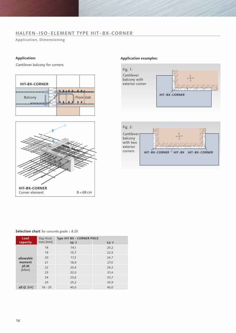
Cantileverbalcony withexterior corner
Cantileverbalconywith twoexteriorcorners
Fig. 1:
Fig. 2:
HALFEN-ISO-ELEMENT TYPE HIT-BX-CORNERApplication, Dimensioning
Balcony Floor slab
HIT-BX-CORNER
HIT-BX-CORNERCorner element
Selection chart
Slap thick-ness [mm]
Loadcapacity
allowablemoment
all.M[kNm]
all.Q [kN]
Type HIT BX - CORNER PIECE
for concrete grade B 25
Application examples:Application:
Cantilever balcony for corners
10/ 7 12/ 7
18
19
20
21
22
23
24
25
18 - 25
14,1
15,7
17,3
18,9
20,4
22,0
23,6
25,2
40,0
20,2
22,5
24,7
27,0
29,2
31,4
33,7
35,9
40,0
B = 68 cm
17
B =
0,6
8 m
B = 0,68 m
0,60
m
B =
0,6
8 m
B = 0,68 m
0,60
m
� �,
�
�
d=
180
-250
mm 50
30
��
�
Z
D
z
80
�
Dimensions in mm
on request
F90normal
Cuntilever slab
Cantilever slab
Floor slab
Floor slabFloor slab
Support
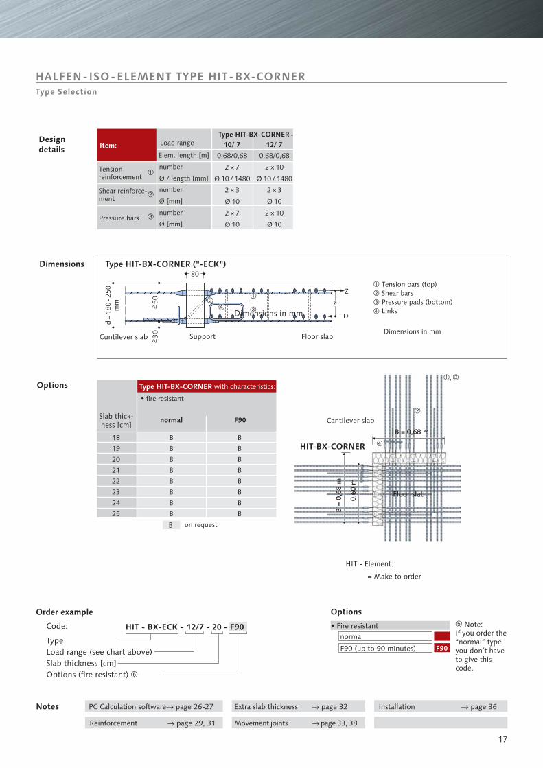
Order example� Note:If you order the“normal” typeyou don´t haveto give thiscode.
Options
• Fire resistantnormal
F90 (up to 90 minutes)
Notes
Code:
TypeLoad range (see chart above)Slab thickness [cm]Options (fire resistant) �
• fire resistant
Type HIT-BX-CORNER ("-ECK")
Tension bars (top)Shear barsPressure pads (bottom)LinksDimensions in mm
Type HIT-BX-CORNER -
number
Ø / length [mm]
number
Ø [mm]
number
Ø [mm]
Slab thick-ness [cm]
Type HIT-BX-CORNER with characteristics:Options
Dimensions
Designdetails
= Make to order
HIT - Element:
HALFEN-ISO-ELEMENT TYPE HIT-BX-CORNERType Selection
Item:Elem. length [m]
Tensionreinforcement
Pressure bars
Shear reinforce-ment
PC Calculation software page 26-27�
Movement joints page 33, 38�Reinforcement page 29, 31�
Installation page 36�Extra slab thickness page 32�
Load range
HIT-BX-CORNER18
19
20
21
22
23
24
25
B
B
B
B
B
B
B
B
B
�
�
�
10/ 7 12/ 7
0,68/0,68
2 × 7
Ø 10 / 1480
2 × 3
Ø 10
2 × 7
Ø 10
0,68/0,68
2 × 10
Ø 10 / 1480
2 × 3
Ø 10
2 × 10
Ø 10
F90
HIT - BX-ECK - 12/7 - 20 - F90
�
�
�
�
B
B
B
B
B
B
B
B
18
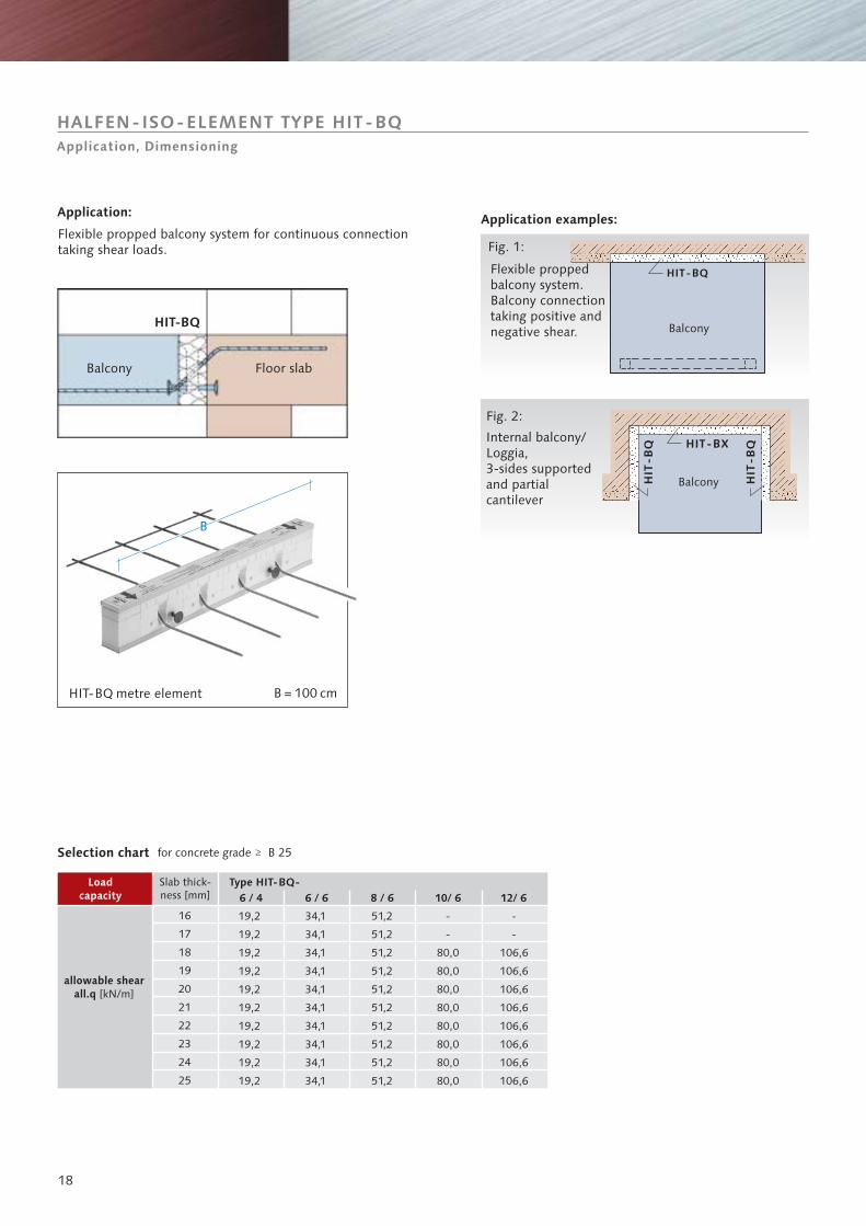
HIT-BQ
HIT-BX
HIT
-BQ
HIT
-BQ
BB
HIT-BQ
Balcony
Fig. 2:
Internal balcony/Loggia,3-sides supportedand partialcantilever
HALFEN-ISO-ELEMENT TYPE HIT-BQApplication, Dimensioning
Application: Application examples:
Flexible proppedbalcony system.Balcony connectiontaking positive andnegative shear.
Fig. 1:
HIT-BQ metre element
Balcony Floor slab
Balcony
Flexible propped balcony system for continuous connectiontaking shear loads.
Selection chart
Slab thick-ness [mm]
Loadcapacity
Type HIT-BQ-
for concrete grade B 25
allowable shearall.q [kN/m]
B = 100 cm
6 / 4 6 / 6 8 / 6 10/ 6 12/ 6
16
17
18
19
20
21
22
23
24
25
19,2
19,2
19,2
19,2
19,2
19,2
19,2
19,2
19,2
19,2
34,1
34,1
34,1
34,1
34,1
34,1
34,1
34,1
34,1
34,1
51,2
51,2
51,2
51,2
51,2
51,2
51,2
51,2
51,2
51,2
-
-
80,0
80,0
80,0
80,0
80,0
80,0
80,0
80,0
-
-
106,6
106,6
106,6
106,6
106,6
106,6
106,6
106,6
19
160
-250
5030
80
�
30
�
80
�
�
�
�
353 / 448Ø 8 / Ø 10
267Ø 6
138
L L
Shape of the shear
reinforcm. Ø 6 mm
Load range
Notes
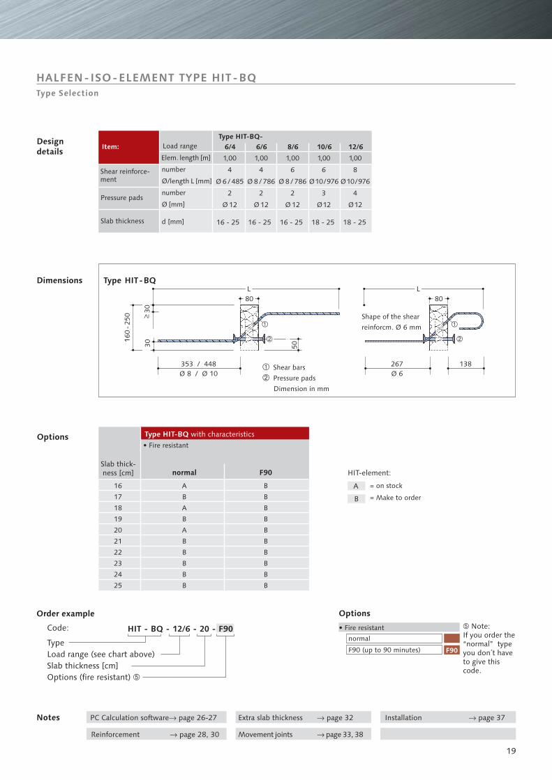
HALFEN-ISO-ELEMENT TYPE HIT-BQType Selection
HIT-element:
Type HIT-BQ
Shear bars
Pressure pads
Dimension in mm
Options
Dimensions
Order example
Code:
TypeLoad range (see chart above)Slab thickness [cm]Options (fire resistant) �
Options
• Fire resistant
Item:Type HIT-BQ-
number
Ø/length L [mm]
number
Ø [mm]
d [mm]
Slab thick-ness [cm]
Type HIT-BQ with characteristics
normal
F90 (up to 90 minutes)
� Note:If you order the“normal” typeyou don´t haveto give thiscode.
• Fire resistant
F90normal
Designdetails
= on stock
= Make to order
Shear reinforce-ment
PC Calculation software page 26-27�
Movement joints page 33, 38�Reinforcement page 28, 30�
Installation page 37�Extra slab thickness page 32�
Elem. length [m]
Pressure pads
Slab thickness
A
B
HIT - BQ - 12/6 - 20 - F90
F90
6/4 6/6 8/6 10/6 12/6
1,00
4
Ø 6 / 485
2
Ø 12
16 - 25 16 - 25 16 - 25 18 - 25 18 - 25
1,00
8
Ø10/976
4
Ø12
1,00
6
Ø10/976
3
Ø12
1,00
6
Ø 8 / 786
2
Ø 12
1,00
4
Ø 8 / 786
2
Ø 12
A
B
A
B
A
B
B
B
B
B
B
B
B
B
B
B
B
B
B
B
16
17
18
19
20
21
22
23
24
25
20
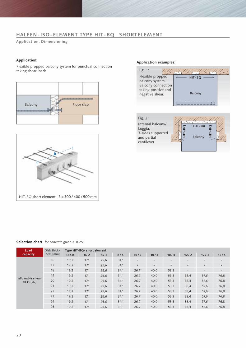
HIT-BQ
HIT-BX
HIT
-BQ
HIT
-BQ
BBBB
Balcony
Fig. 2:
Internal balcony/Loggia,3-sides supportedand partialcantilever
HALFEN-ISO-ELEMENT TYPE HIT-BQ SHORTELEMENTApplication, Dimensioning
Application: Application examples:
Flexible proppedbalcony system.Balcony connectiontaking positive andnegative shear.
Fig. 1:
HIT-BQ short element
Balcony Floor slab
Balcony
Flexible propped balcony system for punctual connectiontaking shear loads.
Selection chart
Slab thick-ness [mm]
Loadcapacity
Type HIT-BQ- short element
for concrete grade B 25
allowable shearall.Q [kN]
B = 300 / 400 / 500 mm
6 / 4 K 8 / 2 8 / 3 8 / 4 10 / 2 10 / 3 10 / 4 12 / 3 12 / 4
16
17
18
19
20
21
22
23
24
25
19,2
19,2
19,2
19,2
19,2
19,2
19,2
19,2
19,2
19,2
17,1
17,1
17,1
17,1
17,1
17,1
17,1
17,1
17,1
17,1
25,6
25,6
25,6
25,6
25,6
25,6
25,6
25,6
25,6
25,6
34,1
34,1
34,1
34,1
34,1
34,1
34,1
34,1
34,1
34,1
-
-
26,7
26,7
26,7
26,7
26,7
26,7
26,7
26,7
-
-
40,0
40,0
40,0
40,0
40,0
40,0
40,0
40,0
-
-
53,3
53,3
53,3
53,3
53,3
53,3
53,3
53,3
-
-
-
57,6
57,6
57,6
57,6
57,6
57,6
57,6
-
-
-
76,8
76,8
76,8
76,8
76,8
76,8
76,8
12 / 2
-
-
-
38,4
38,4
38,4
38,4
38,4
38,4
38,4
21
160
-250
5030
80
�
30
�
80
�
�
�
�
353 / 448 / 531Ø 8 / Ø 10 / Ø 12
267Ø 6
138
LL
number
Ø/length L [mm]
number
Ø [mm]
= on stock
= Make to order
= not available for types HIT-BQ-10/2, -/3, -/4
= not available for types HIT-BQ-12/2, -/3, -/4
Load range
Notes
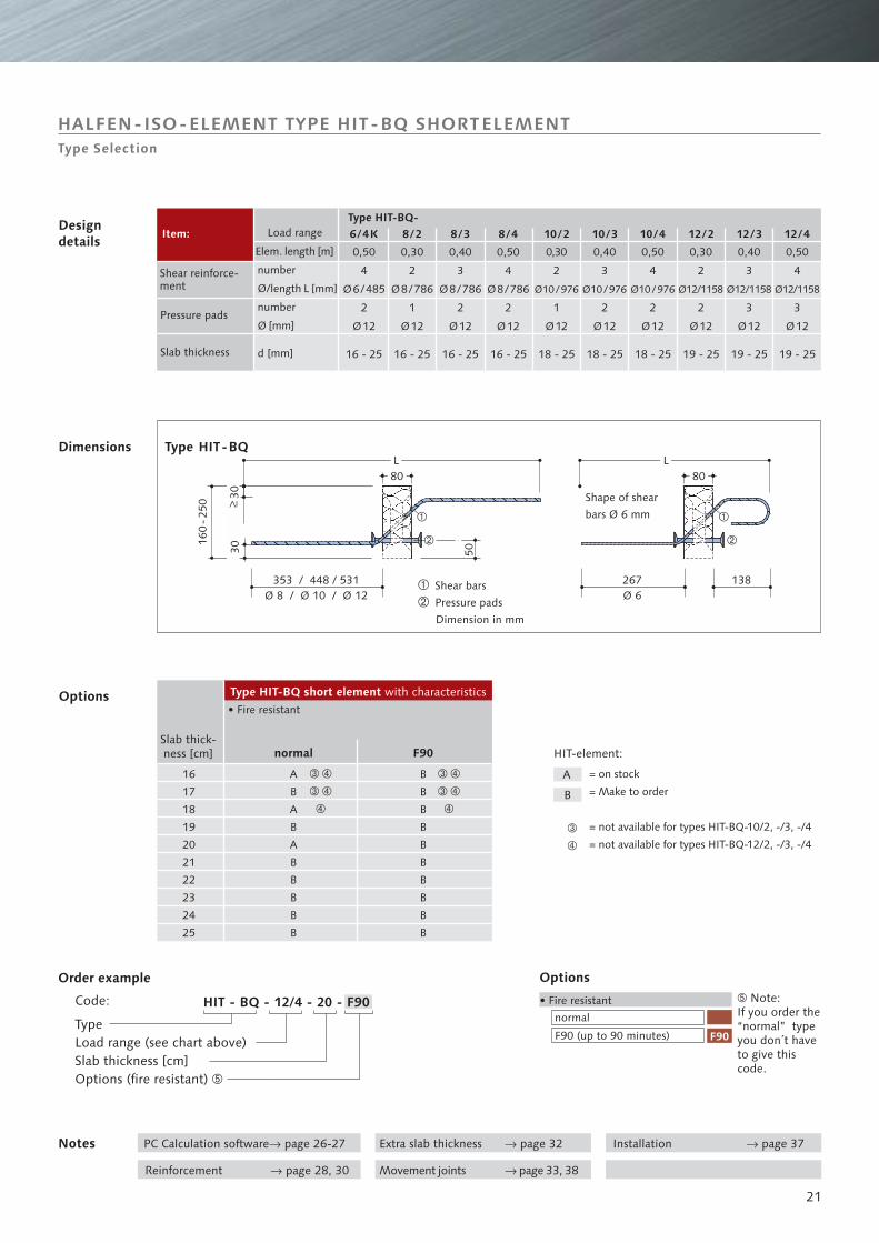
HALFEN-ISO-ELEMENT TYPE HIT-BQ SHORTELEMENTType Selection
HIT-element:
Type HIT-BQ
Shear bars
Pressure pads
Dimension in mm
Options
Dimensions
Order example
Code:
TypeLoad range (see chart above)Slab thickness [cm]Options (fire resistant) �
Options
• Fire resistant
Item:Type HIT-BQ-
d [mm]
Slab thick-ness [cm]
Type HIT-BQ short element with characteristics
normal
F90 (up to 90 minutes)
� Note:If you order the“normal” typeyou don´t haveto give thiscode.
• Fire resistant
F90normal
Designdetails
Shear reinforce-ment
PC Calculation software page 26-27�
Movement joints page 33, 38�Reinforcement page 28, 30�
Installation page 37�Extra slab thickness page 32�
Elem. length [m]
Pressure pads
Slab thickness
Shape of shear
bars Ø 6 mm
A
B
HIT - BQ - 12/4 - 20 - F90
F90
6/4K 8/2 8/3 8/4 10/2
0,50
4
Ø6/485
2
Ø12
16 - 25 16 - 25 16 - 25 16 - 25 18 - 25
0,30
2
1
Ø12
Ø10/976
0,50
4
Ø8/786
2
Ø12
0,40
3
Ø8/786
2
Ø12
0,30
2
Ø8/786
1
Ø12
A
B
A
B
A
B
B
B
B
B
���
���
�
B
B
B
B
B
B
B
B
B
B
16
17
18
19
20
21
22
23
24
25
10/3 10/4 12/2 12/3 12/4
0,40
3
2
Ø12
0,50
4
2
Ø12
0,30
2
2
Ø12
0,40
3
3
Ø12
0,50
4
3
Ø12
18 - 25 18 - 25 19 - 25 19 - 25 19 - 25
���
���
�
�
�
Ø12/1158 Ø12/1158 Ø12/1158Ø10/976 Ø10/976
22
HIT-±BQ
BBB
Selection chart
Slab thick-ness [mm]
Loadcapacity
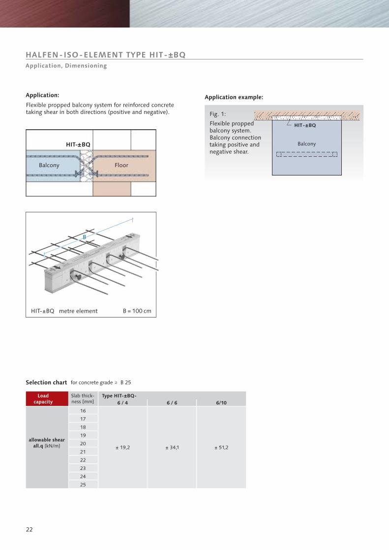
Application: Application example:
Flexible proppedbalcony system.Balcony connectiontaking positive andnegative shear.
Fig. 1:
HIT-±BQ metre element
Balcony Floor
HIT- BQ± Balcony
Flexible propped balcony system for reinforced concretetaking shear in both directions (positive and negative).
Type HIT-±BQ-
for concrete grade B 25
HALFEN-ISO-ELEMENT TYPE HIT-±BQApplication, Dimensioning
allowable shearall.q [kN/m]
B = 100 cm
6 / 4 6 / 6 6/10
16
17
18
19
20
21
22
23
24
25
± 19,2 ± 34,1 ± 51,2
23
80
�
�
�
160
-250
5030
80
�
30
�
50
353Ø 8
267Ø 6
�
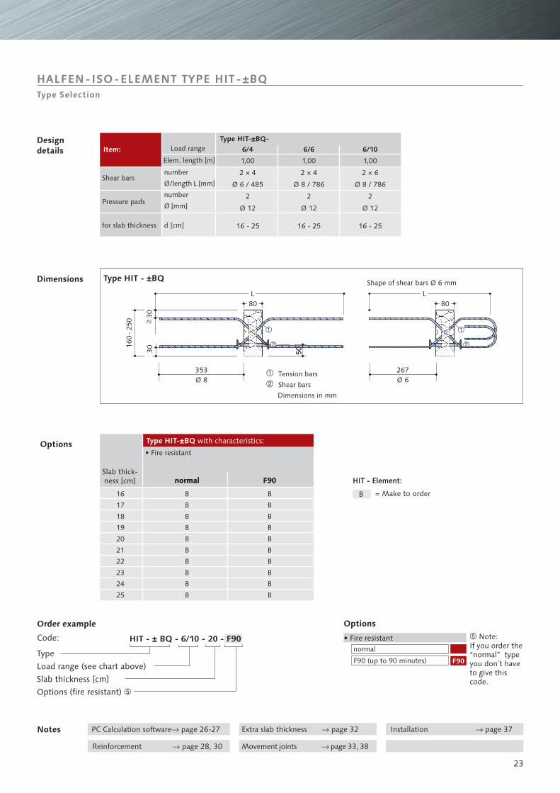
Shape of shear bars Ø 6 mm
Load range
Tension bars
Shear bars
Dimensions in mm
Type HIT - ±BQ
Item:Type HIT-±BQ-
HALFEN-ISO-ELEMENT TYPE HIT-±BQType Selection
Dimensions
Designdetails
number
Ø/length L [mm]
number
Ø [mm]
Elem. length [m]
Shear bars
Pressure pads
for slab thickness
F90
= Make to order
HIT - Element:
Type HIT-±BQ with characteristics:
normal
Notes
HIT - Element:
Options
Order example
Code:
Type
Load range (see chart above)
Slab thickness [cm]
Options (fire resistant) �
Options
• Fire resistant
Slab thick-ness [cm]
normal
F90 (up to 90 minutes)
� Note:If you order the“normal” typeyou don´t haveto give thiscode.
• Fire resistant
F90normal
PC Calculation software page 26-27�
Movement joints page 33, 38�Reinforcement page 28, 30�
Installation page 37�Extra slab thickness page 32�
d [cm]
B
1,00
2 × 4
Ø 6 / 485
2
Ø 12
16 - 25 16 - 25
1,00
2 × 4
Ø 8 / 786
2
Ø 12
B
B
B
B
B
B
B
B
B
B
B
B
B
B
B
B
B
B
B
B
16
17
18
19
20
21
22
23
24
25
1,00
2 × 6
Ø 8 / 786
2
Ø 12
16 - 25
6/4 6/6 6/10
HIT - ± BQ - 6/10 - 20 - F90
F90
L L
24
�
HIT
-BD
HIT
-BQ
HIT-BD
HIT
-BD
HIT
-BQ
BBB
Fig. 2:
Balcony
Balcony
2nd layer
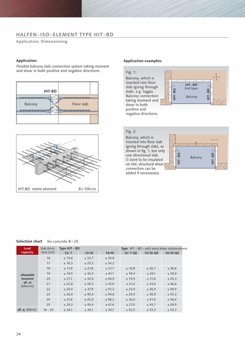
Application:
Balcony, which isinserted into floorslab (going throughslab), e.g. loggia.Balcony connectiontaking moment andshear in bothpositive andnegative directions.
Balcony, which isinserted into floor slab(going through slab), asshown in fig. 1, but onlyone-directional slab.
Joint to be insulatedon site; structural shearconnection can beadded if necessesary.
�
Fig. 1:
Type HIT - BD Type -HIT - BD with extra shear reinforcement
Balcony Floor slab
HIT-BD
Flexible balcony slab connection system taking momentand shear in both directions.positive and negative
Application examples:
HIT-BD metre element
HALFEN-ISO-ELEMENT TYPE HIT-BDApplication, Dimensioning
Selection chart
Slab thick-ness [cm]
Loadcapacity
for concrete B 25
allowablemoment
all. m[kNm/m]
all. q [kN/m]
B=100cm
12/ 7 12/10 14/10 12/ 7-QE 12/10-QE 14/10-QE
16
17
18
19
20
21
22
23
24
25
16 - 25
± 14,6
± 16,3
± 17,9
± 19,5
± 21,1
± 22,8
± 24,4
± 26,0
± 27,6
± 29,3
± 34,1
± 22,7
± 25,2
± 27,8
± 30,3
± 32,8
± 35,3
± 37,9
± 40,4
± 42,9
± 45,4
± 34,1
± 30,8
± 34,2
± 37,7
± 41,1
± 44,5
± 47,9
± 51,3
± 54,8
± 58,2
± 61,6
± 34,1
± 16,8
± 18,4
± 19,9
± 21,4
± 23,0
± 24,5
± 26,0
± 27,5
± 53,3
± 26,7
± 29,1
± 31,6
± 34,0
± 36,4
± 38,9
± 41,3
± 43,7
± 53,3
± 36,6
± 39,9
± 43,3
± 46,6
± 49,9
± 53,2
± 56,6
± 59,9
± 53,3
25
Z
D
z
160
-250 30
30
80
�
�
Z
D
z
200
-250 50
50
�
�
80
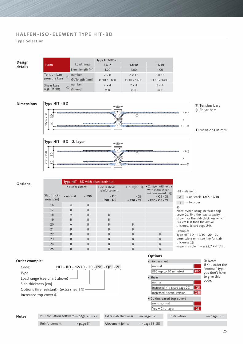
Note: When using increased topcover , find the load capacityshown for the slab thickness whichis 4
.
Example:Type HIT-BD - 12/10 - -permissible m see line for slabthickness
2L
2L
cm less than the actualthickness (chart page 24)
permissible m = ± 22,7 kNm/m .
20�
16�
HIT - element:
Load range
• Fire resistant • extra shearreinforcement
• 2. layer • 2. layer with extrawith extra shearreinforcement
Slab thick-ness [cm]
Type HIT - BD with characteristics:
Tension barsShear bars
Dimensions in mm
Type HIT - BD
Item:Type HIT-BD-
number
Ø / length [mm]
number
Ø [mm]
Tension bars,pressure bars
HALFEN-ISO-ELEMENT TYPE HIT-BDType Selection
Options
Dimensions
Designdetails
Shear bars(QE: Ø 10)
Elem. length [m]
• 2L (increased top cover)
Order example:Options• Fire resistant
• Shear
no = normal
Yes = 2nd layer
normal
F90 (up to 90 minutes)
Notes PC Calculation software page 26 - 27�
Movement joints page 33, 38�Reinforcement page 31�
Installation page 36�Extra slab thickness page 32�
Code:
� Note:If You order the“normal” typeyou don´t haveto give thiscode.
TypeLoad range (see chart above)Slab thickness [cm]Options (fire resistant), (extra shear)Increased top cover
�
�
normal
chart page 22�increased ( )
increased, special version
= on stock: ,12/7 12/10
= to order
Type HIT - BD - 2. layer
�
�
12/ 7 12/10 14/10
1,00
2 × 8
Ø 10 / 1480
2 × 4
Ø 8
1,00
2 × 12
Ø 10 / 1480
2 × 4
Ø 8
1,00
2 × 16
Ø 10 / 1480
2 × 4
Ø 8
- normal - QE - 2L- F90 - QE - 2L
- QE- F90 - QE
- 2L- F90 - 2L
A
B
F90
QE
QEE
2L
16
17
18
19
20
21
22
23
24
25
A
B
A
B
A
B
B
B
B
B
B
B
B
B
B
B
B
B
B
B
B
B
B
B
�
�
�
B
B
B
B
�
�
HIT - BD - 12/10 - 20 - F90 - QE - 2L
- F90
B
B
B
B
B
B
B
B
B
B
26
➀ ➁
➃
➅
➄
➂
➆
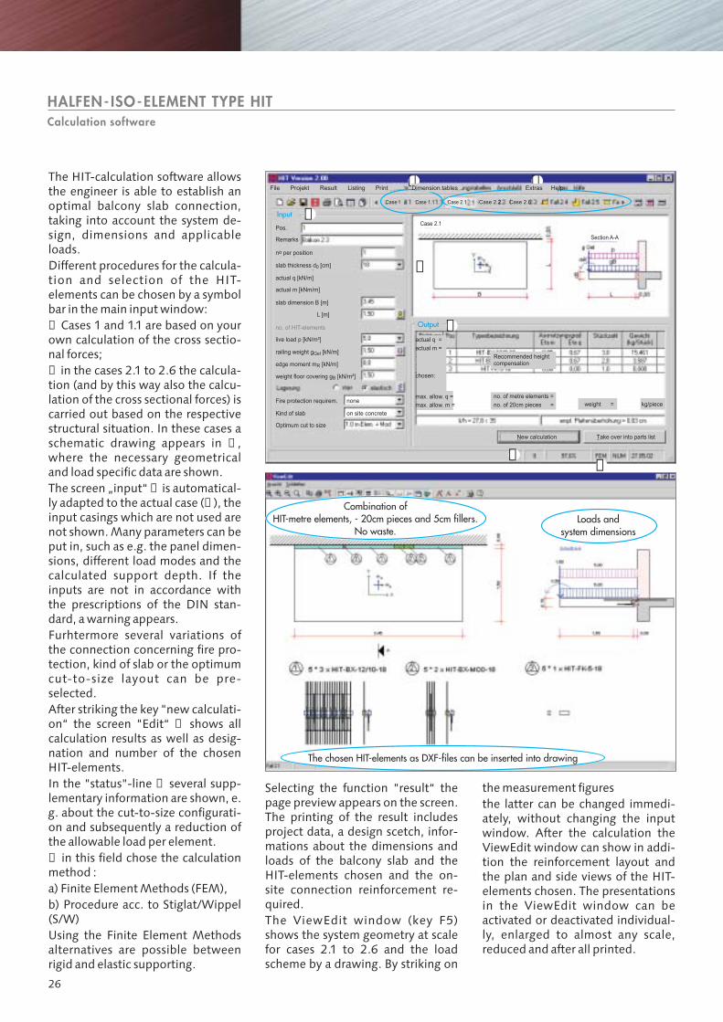
The chosen HIT-elements as DXF-files can be inserted into drawing
Combination ofHIT-metre elements, - 20cm pieces and 5cm fillers.
No waste.Loads and
system dimensions
HALFEN- ISO-ELEMENT TYPE HITCalculation software
Case 2.6
HelpExtrasDimension.tablesPrintListingResultFile Projekt
Case 2.2Case 2.1
Case 2.1
Section A-A
Case 1.1Case1
Pos.
Remarks
n per positiono
slab thickness d [cm]0
actual q [kN/m]
actual q =
Recommended heightcompensation
no. of metre elements =
no. of 20cm pieces = weight = kg/piece
max. allow. q =
max. allow. m =
chosen:
New calculation Take over into parts list
actual m [kNm/m]
actual m =
slab dimension B [m]
L [m]
no. of HIT-elements
live load p [kN/m²]
railing weight g [kN/m]Gel
edge moment m [kN/m]R
weight floor covering g [kN/m²]B
Fire protection requirem. none
Kind of slab on site concrete
Optimum cut to size
Input
Output
The HIT-calculation software allowsthe engineer is able to establish anoptimal balcony slab connection,taking into account the system de-sign, dimensions and applicableloads.
Furhtermore several variations ofthe connection concerning fire pro-tection, kind of slab or the optimumcut-to-size layout can be pre-selected.
In the "status"-line several supp-lementary information are shown, e.g. about the cut-to-size configurati-on and subsequently a reduction ofthe allowable load per element.in this field chose the calculation
method :a) Finite ElementMethods (FEM),b) Procedure acc. to Stiglat/Wippel(S/W)Using the Finite Element Methodsalternatives are possible betweenrigid and elastic supporting.
Different procedures for the calcula-tion and selection of the HIT-elements can be chosen by a symbolbar in themain inputwindow:Cases 1 and 1.1 are based on your
own calculation of the cross sectio-nal forces;in the cases 2.1 to 2.6 the calcula-
tion (and by this way also the calcu-lation of the cross sectional forces) iscarried out based on the respectivestructural situation. In these cases aschematic drawing appears in ,where the necessary geometricaland load specific data are shown.The screen „input“ is automatical-ly adapted to the actual case ( ), theinput casings which are not used arenot shown.Many parameters can beput in, such as e.g. the panel dimen-sions, different load modes and thecalculated support depth. If theinputs are not in accordance withthe prescriptions of the DIN stan-dard, awarning appears.
After striking the key "new calculati-on“ the screen "Edit“ shows allcalculation results as well as desig-nation and number of the chosenHIT-elements.
➀
➁
➃
➂➀
➄
➅
➆
Selecting the function "result“ thepage preview appears on the screen.The printing of the result includesproject data, a design scetch, infor-mations about the dimensions andloads of the balcony slab and theHIT-elements chosen and the on-site connection reinforcement re-quired.The ViewEdit window (key
2.1 to 2.6 and the loadscheme by a drawing. By striking on
F5)shows the system geometry at scalefor cases
themeasurement figuresthe latter can be changed immedi-ately, without changing the inputwindow. After the calculation theViewEdit window can show in addi-tion the reinforcement layout andthe plan and side views of the HIT-elements chosen. The presentationsin the ViewEdit window can beactivated or deactivated individual-ly, enlarged to almost any scale,reduced and after all printed.
27
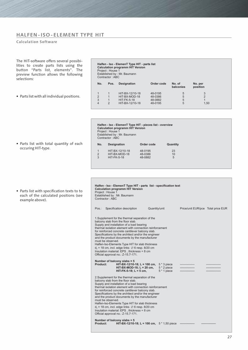
Halfen - Iso - ElemenT Type HIT - parts list - specification text
Number of balcony slabs = 5Product: HIT-BX-12/10-18; L = 100 cm,
HIT-BX-MOD-18; L = 20 cm,HIT-FK-5-18; L = 5 cm,
Calculation programm HIT Version
Number of balcony slabs = 5Product: HIT-BX-12/10-18; L = 100 cm,
Project : House 1Established by : Mr. BaumannContractor : ABC
cantilever
piecepiece
2.Supplement for the thermal separation of thebalcony slab from the floor slab.Supply and installation of a load bearingthermal isolation element with connection reinforcementfor reinforced concrete cantilever balcony slab.Specifications by the architect and/or the engineerand the product documents by the manufacturermust be observed.Halfen-Iso-Elements Type HIT for slab thickness
5 * 1,50 piece --------------- ---------------
Pos.: Specification description Quantity/unit Price/unit EUR/pce Total price EUR
1.Supplement for the thermal separation of thebalcony slab from the floor slab.Supply and installation of a load bearingthermal isolation element with connection reinforcementfor reinforced concrete balcony slab.Specifications by the architect and/or the engineerand the product documents by the manufacturermust be observed.Halfen-Iso-Elements Type HIT for slab thickness
d = 18 cm, incl. edge links 6 resp. 8/20 cm
Insulation material: EPS , thickness = 8 cmOfficial approval no.: Z-15.7-171.
5 * 3 piece --------------- ---------------5 * 2 --------------- ---------------5 * 1 --------------- ---------------
d = 18 cm, incl. edge links 6 resp. 8/20 cm
Insulation material: EPS , thickness = 8 cmOfficial approval no.: Z-15.7-171.
0
0
�
�
Halfen - Iso - ElemenT Type HIT - parts listCalculation programm HIT Version
No. Pos. Designation Order code No. of No. perbalconies position
Project : House 1Established by : Mr. BaumannContractor : ABC
1 1 HIT-BX-12/10-18 48-0195 5 32 1 HIT-BX-MOD-18 48-0386 5 23 1 HIT-FK-5-18 48-0882 5 14 2 HIT-BX-12/10-18 48-0195 5 1,50
Halfen - Iso - ElemenT Type HIT - pieces list - overviewCalculation programm HIT Version
No. Designation Order code Quantity
Project : House 1Established by : Mr. BaumannContractor : ABC
1 HIT-BX-12/10-18 48-0195 232 HIT-BX-MOD-18 48-0386 103 HIT-FK-5-18 48-0882 5
HALFEN-ISO-ELEMENT TYPE HITCalculation Software
• Parts list with all individual positions.
• Parts list with total quantity of eachoccuringHIT-type.
• Parts list with specification texts to toeach of the calculated positions (seeexample above).
The HIT-software offers several possibi-lities to create parts lists using thebutton “Parts list, elements”. Thepreview function allows the followingselections:
28
B 25
➄
➂
➃➁➂
➀➀➈
➄ ➄
➅ ➅
➆ ➆➇ ➇ B 25B 25
A
A
d=
160
-250
mm 30
30 30
30
➆ ➆
30
➆
➀➂➃
2,00
m
➄
➅
➄
➅
➇➇
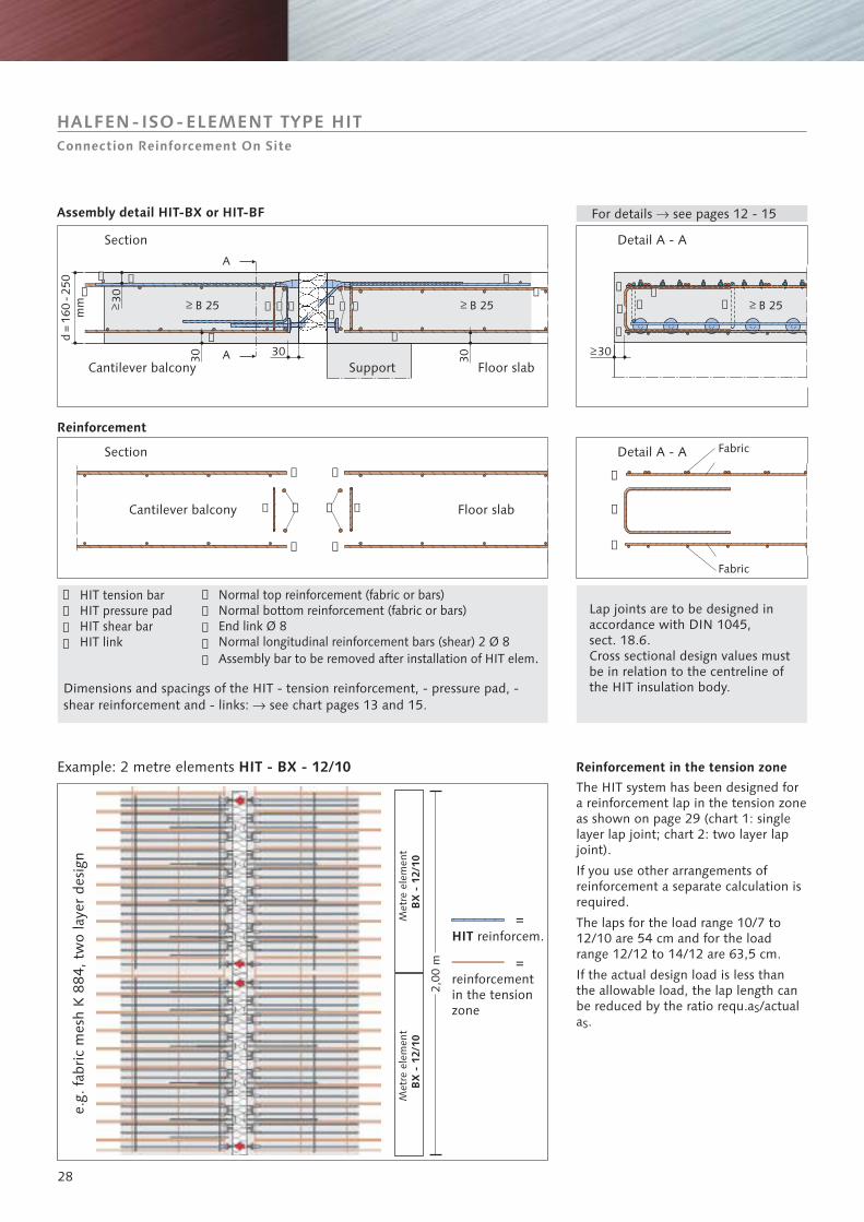
The HIT system has been designed fora reinforcement lap in the tension zoneas shown on page 29 (chart 1: singlelayer lap joint; chart 2: two layer lapjoint).
If you use other arrangements ofreinforcement a separate calculation isrequired.
The laps for the load range 10/7 to12/10 are 54 cm and for the loadrange 12/12 to 14/12 are 63,5 cm.
If the actual design load is less thanthe allowable load, the lap length canbe reduced by the ratio requ.a /actuala .
S
S
For details see pages 12 - 15�
Detail A - A
Detail A - A
Section
Assembly detail HIT-BX or HIT-BF
Reinforcement
Reinforcement in the tension zone
Section
Support Floor slab
Floor slab
Cantilever balcony
Cantilever balcony
HIT tension barHIT pressure padHIT shear barHIT link
Dimensions and spacings of the HIT - tension reinforcement, - pressure pad, -shear reinforcement and - links: see chart pages 13 and 15.�
Example: 2 metre elements HIT - BX - 12/10
e.g.
fabr
ic m
esh
K 8
84, t
wo
laye
r de
sign
Normal top reinforcement (fabric or bars)Normal bottom reinforcement (fabric or bars)End link Ø 8Normal longitudinal reinforcement bars (shear) 2 Ø 8Assembly bar to be removed after installation of HIT elem.
Lap joints are to be designed inaccordance with DIN 1045,sect. 18.6.Cross sectional design values mustbe in relation to the centreline ofthe HIT insulation body.
Fabric
Fabric
Met
re e
lem
ent
Met
re e
lem
ent
=reinforcementin the tensionzone
=HIT reinforcem.
HALFEN-ISO-ELEMENT TYPE HITConnection Reinforcement On Site
BX
- 1
2/10
BX
- 1
2/10
➀
➁
➂
➃
➄
➅
➆
➇
➈
➄
➅
➆
29
�
�
��
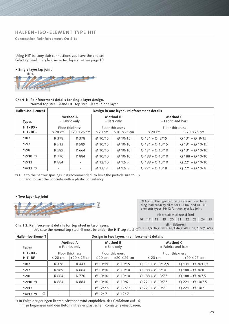
� Acc. to the type test certificateall.m for HIT-BX- and HIT-BF-
elements types 14/12 for two layer lap joint
reduced ben-ding load capacity
all.m [kNm/m]
Floor slab thickness d [cm]
Types
*) Due to the narrow spacings it is recommended, to limit the particle size to 16mm and to cast the concrete with a plastic consistency.
HALFEN-ISO-ELEMENT TYPE HITConnection Reinforcement On Site
Using balcony slab connections you have the choice:HITSelect top steel in single layer or two layers see page 10.�
• Single layer lap joint
Chart 1: Reinforcement details for single layer design.HITNormal top steel and top steel are in one layer.� �
Chart 2: Reinforcement details for top steel in two layers.HITIn this case the normal top steel must be the top steel� �under
• Two layer lap joint
Halfen-Iso-ElemenT
Halfen-Iso-ElemenT
Design in one layer - reinforcement details
Design in two layers - reinforcement details
Floor thickness
Floor thickness
Floor thickness
Floor thickness
Floor thickness
Floor thickness
Method A= Fabric only
Method A= Fabrics only
Method B= Bars only
Method B= Bars only
Method C= Fabric and bars
Method C= Fabrics and barsTypes
HIT-BX-HIT-BF-
16
29,9
17
33,5
18
36,7
19
39,9
20
43,3
21
46,7
22
49,9
23
53,7
24
57,1
25
60,7
20 cm 20 cm 20 cm
Q 131 + Ø 8/15
Q 131 + Ø 10/15
Q 131 + Ø 10/10
Q 188 + Ø 10/10
Q 188 + Ø 10/10
Q 221 + Ø 10/ 8
Q 131 + Ø 8/15
Q 131 + Ø 10/15
Q 131 + Ø 10/10
Q 188 + Ø 10/10
Q 221 + Ø 10/10
Q 221 + Ø 10/ 8
Q 131 + Ø 8/12,5
Q 188 + Ø 8/10
Q 188 + Ø 8/7,5
Q 221 + Ø 10/7,5
Q 221 + Ø 10/7
-
Q 131 + Ø 8/12,5
Q 188 + Ø 8/10
Q 188 + Ø 8/7,5
Q 221 + Ø 10/7,5
Q 221 + Ø 10/7
-
R 378
R 513
R 589
K 770
K 884
-
R 378
R 589
R 664
K 884
-
-
Ø 10/15
Ø 10/10
Ø 10/10
Ø 10/10
Ø 12/7,5
Ø 12/ 7
Ø 10/15
Ø 10/10
Ø 10/10
Ø 10/6
Ø 12/7,5
Ø 12/ 7
10/7
12/7
12/8
12/10 *)
12/12
14/12 *)
*) In Folge der geringen lichten Abstände wird empfohlen, das Größtkorn auf 16mm zu begrenzen und den Beton mit einer plastischen Konsistenz einzubauen.
R 378
R 589
K 664
K 884
-
-
Ø 10/15
Ø 10/15
Ø 10/10
Ø 10/10
Ø 12/10
Ø 12/ 8
Ø 10/15
Ø 10/10
Ø 10/10
Ø 10/10
Ø 12/ 9
Ø 12/ 8
R 443
K 664
K 770
K 884
-
-
>20 25 cm >20 25 cm >20 25 cm
20 cm 20 cm 20 cm>20 25 cm >20 25 cm >20 25 cm
�
10/7
12/7
12/8
12/10
12/12
14/12
*)
*)
HIT-BX-HIT-BF-
d=
160
-250
mm
d=
160
-250
mm
➆
➆
➆
➄
➅
➄
➅
➄
➅
➄
➅
lü
lü
lü
lü➇ ➇
➇ ➆ ➇
B 25
B 25
B 25
B 25
30
➈ ➈
➈ ➈
5050
3030
80
80
➀➀
➀
3030
➁
➁
Connection Reinforcement On Site
Links: requ. cross section per elementaS
Connection Reinforcement On Site
Longitudinal section
Longitudinal section
Floor slab
Floor slab
Balcony slab
Balcony slab
Longitudinal section
Longitudinal section
Support
Support
Floor slab
Floor slab
Balcony slab
Balcony slab
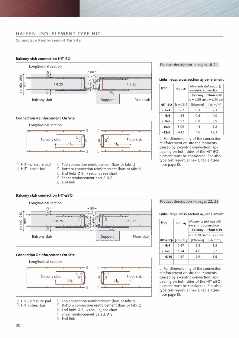
Balcony slab connection HIT-BQ
Balcony slab connection HIT-±BQ
HIT - pressure padHIT - shear bar
HIT - pressure padHIT - shear bar
Top connection reinforcement (bars or fabric).
End links Ø 8 requ. a see chartShear reinforcement bars 2 Ø 8
�
Bottom connection reinforcement (bars or fabric).
End link
S
➉ For dimensioning of the connectionreinforcement on site the momentscaused by excentric connection, ap-pearing on both sides of the HIT-BQ-element must be considered. See alsotype test report, annex 1, table 1(seenote page 8).
Top connection reinforcement (bars or fabric).Bottom connection reinforcement (bars or fabric).End links Ø 8 requ. a see chartShear reinforcement bars 2 Ø 8End link
� S
Type requ.aSMoments M out ofexcentric connection
∆
Balcony Floor slab
Product description pages 18-21�
HALFEN-ISO-ELEMENT TYPE HITConnection Reinforcement On Site
Links: requ. cross section per elementaS
Type requ.aSMoments M out ofexcentric connection
∆
Balcony Floor slab
Product description pages 22, 23�
➉ For dimensioning of the connectionreinforcement on site the momentscaused by excentric connection, ap-pearing on both sides of the HIT-±BQ-element must be considered. See alsotype test report, annex 1, table 1(seenote page 8).
[cm²/El.] [kNm/m]
d = 25 cm
[kNm/m]
d = 20 cm
- 6/4
- 6/6
- 8/6
-10/6
-12/6
HIT-BQ-
0,67
1,24
1,97
3,09
4,12
0,3
0,6
0,9
1,4
1,8
2,3
4,0
5,9
9,2
12,3
➁
➂
➁
➂
➄
➅
➆
➇
➈
➄
➅
➆
➇
➈
➉
[cm²/El.] [kNm/m]
d = 20 cm
[kNm/m]
d = 25 cm
- 6/4
- 6/6
- 6/10
HIT-±BQ-
0,67
1,24
1,97
2,3
4,0
5,9
3,2
5,7
8,5
➉
31
11
1
22
2
33
3
��
�
�
�
�
160
-250
3030
80�
�
�
�
A
A 30
�
�
�
�
�
�
�
�
�
�
�
300 300 l1� �
B 25B 25B 25 �
4 4
4
6
6
5
5
7
7
5 7
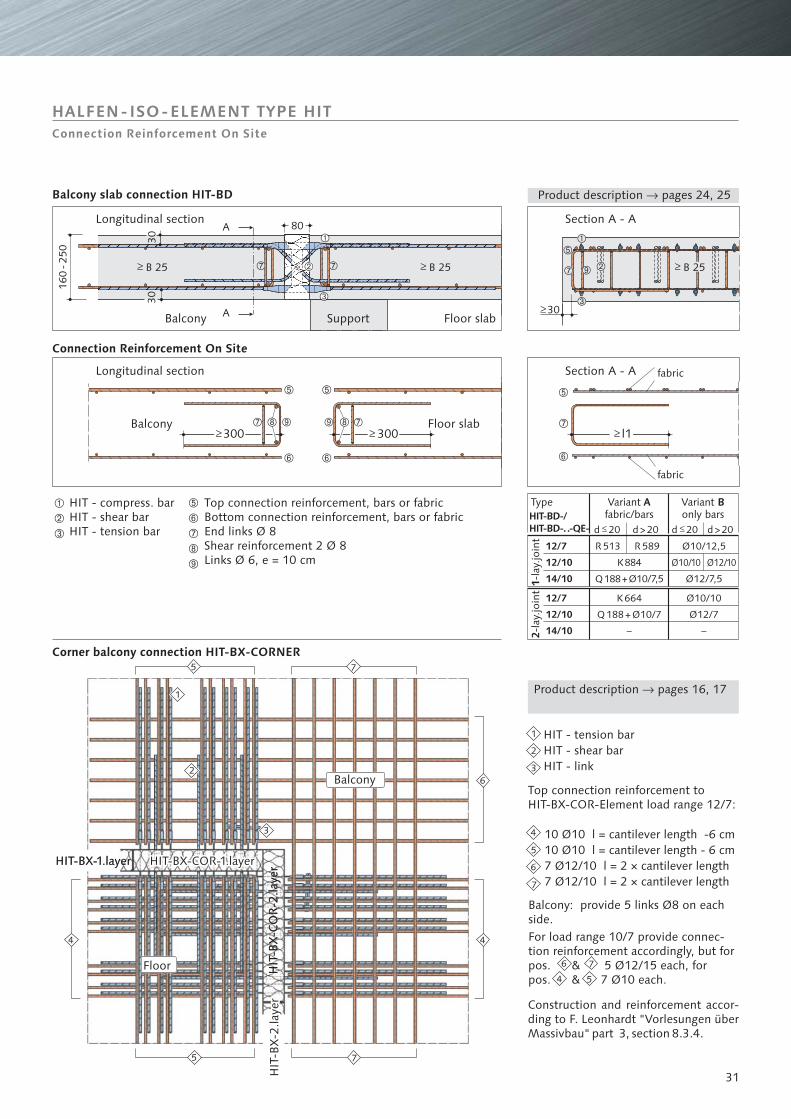
Product description pages 24, 25�
Section A - A
Section A - A fabric
fabric
Connection Reinforcement On Site
Longitudinal section
Floor slabBalcony
Longitudinal section
Support Floor slabBalcony
Balcony slab connection HIT-BD
HIT - compress. barHIT - shear barHIT - tension bar
HIT - tension barHIT - shear barHIT - link
Top connection reinforcement,bars or fabric
bars or fabricBottom connection reinforcement,End links Ø 8Shear reinforcement 2 Ø 8Links Ø 6, e = 10 cm
10 Ø10 l = cantilever length -6 cm10 Ø10 l = cantilever length - 6 cm7 Ø12/10 l = 2 × cantilever length7 Ø12/10 l = 2 × cantilever length
Construction and reinforcement accor-ding to F. Leonhardt "Vorlesungen überMassivbau" part 3, section 8.3.4.
Top connection reinforcement toElement load range 12/7:HIT-BX-COR-
Balcony: provide 5 links Ø8 on eachside.For load range 10/7 provide connec-tion reinforcement accordingly, but forpos. & 5 Ø12/15 each, forpos. & 7 Ø10 each.
Corner balcony connection HIT-BX-CORNER
Product description pages 16, 17�
Balcony
HIT-BX-COR-1.layerHIT-BX-COR-1.layer
HIT
-BX
-CO
R-2
.laye
rHIT-BX-COR-1.layer
HIT
-BX
-CO
R-2
.laye
rHIT-BX-1.layer
HIT
-BX
-2.la
yer
HIT
-BX
-2.la
yer
HIT
-BX
-2.la
yer
HIT-BX-1.layer
Floor
Variantfabric/bars
AType
1-la
y.jo
int
2-la
y.jo
int
Variantonly bars
B
HALFEN-ISO-ELEMENT TYPE HITConnection Reinforcement On Site
4
6
5
7
12/7
12/10
14/10
K884
Q188+Ø10/7,5
R 513
Ø10/10
R 589
Ø12/10
Ø10/12,5
Ø12/7,5
12/7
12/10
14/10
K664
Q188+Ø10/7
–
Ø10/10
Ø12/7
–
HIT-BD-/HIT-BD-..-QE- d 20 d 20d>20 d>20
�
�
�
�
�
�
�
�
32
lK8 cm b
2b2 �
�lK
ü
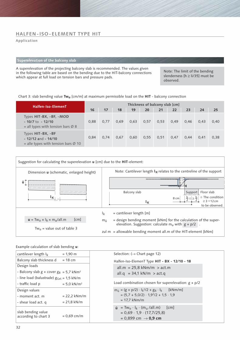
Superelevation of the balcony slab
Halfen-Iso-ElemenT Thickness of balcony slab [cm]
Note: Cantilever length relates to the centreline of the supportlK
Support Floor slab
The condition
to be observed.
Balcony slab
Types HIT-BX, -BF, -MOD
Types HIT-BX, -BF
- 10/7 - 12/10to
- 12/12 a - 14/10nd
= all types with tension bars Ø 8
= alle types with tension bars Ø 10
Design values
- moment act. m
- shear load act. q
Design loads
- Balcony slab g + cover g
- line load (balustrade) g
- traffic load p
B
Gel.
cantilever length l
Balcony slab thickness dk
slab bending valueaccording to chart 3
Selection: ( Chart page 12)�
Halfen-Iso-ElemenT Type
Load combination chosen for superelevation: g + p/2
all.m = 25,8 kNm/m > act.mall.q = 34,1 kN/m > act.q
Tw = value out of table 3u
u = × l × m /all.mk uTwu
Dimension (schematic, enlarged height)u
Example calculation of slab bending :u
= cantilever length [m]
= design bending moment [kNm] for the calculation of the super-elevation. Suggestion: calculate m with g + p/2 .u
= allowable bending moment all.m of the HIT-element [kNm]
= · l · (m /all.m) [cm]= 0,69 · 1,9 · (17,7/25,8)= 0,899 cm
Twu k u
� 0,9 cm
Suggestion for calculating the superelevation [cm] due to the -element:u HIT
A superelevation of the projecting balcony slab is recommended. The values givenin the following table are based on the bending due to the HIT-balcony connectionswhich appear at full load on tension bars and pressure pads.
Note: The limit of the bendingslenderness [h li/35] must beobserved.
�
Chart 3: slab bending value [cm/m] at maximum permissible load on the - balcony connectionTw HITu
HALFEN-ISO-ELEMENT TYPE HITApplication
3 12cm
mü
ü
= (g + p/2) · l ²/2 + g · l [kNm/m]= (5,7 + 5,0/2) · 1,9²/2 + 1,5 · 1,9= 17,7 kNm/m
k R k
HIT - BX - 12/10 - 18
16 17 18 19 20 21 22 23 24 25
0,88
0,84
0,77
0,74
0,69
0,67
0,63
0,60
0,57
0,55
0,53
0,51
0,49
0,47
0,46
0,44
0,43
0,41
0,40
0,38
= 1,90 m
= 18 cm
= 5,7 kNm²
= 1,5 kN/m
= 5,0 kN/m²
= 22,2 kNm/m
= 21,8 kN/m
= 0,69 cm/m
lk
mü
zul m
[cm]
33
11,30 m 5,65 m
L
5,65
m
HIT-BX HIT-BX
HIT-BX
HIT-BX
HIT-BX-ECK
80mm
515 cm
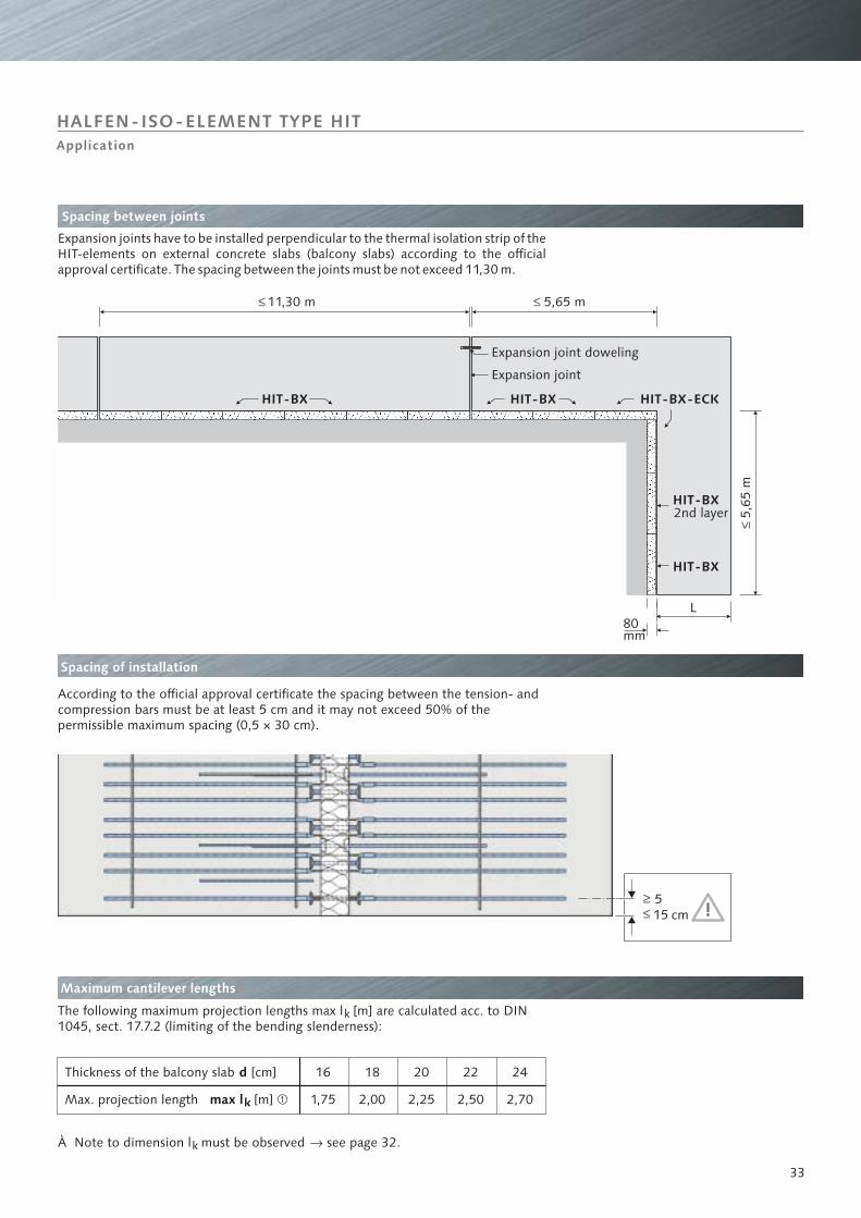
Spacing between joints
Expansion joints have to be installed perpendicular to the thermal isolation strip of theHIT-elements on external concrete slabs (balcony slabs) according to the officialapproval certificate. The spacing between the joints must be not exceed 11,30 m.
2nd layer
Spacing of installation
According to the official approval certificate the spacing between the tension- andcompression bars must be at least 5 cm and it may not exceed 50% of thepermissible maximum spacing (0,5 × 30 cm).
Maximum cantilever lengths
The following maximum projection lengths max l [m] are calculated acc. to DIN1045, sect. 17.7.2 (limiting of the bending slenderness):
k
Thickness of the balcony slab
Max. projection length
À Note to dimension l must be observed see page 32.k �
Expansion joint
HALFEN-ISO-ELEMENT TYPE HIT
Expansion joint doweling
Application
d [cm]
max lk [m] �
16
1,75
18
2,00
20
2,25
22
2,50
24
2,70
34
➆ ➅
HIT-BF
➄
➄
➄
➇
➀ ➂➃
➅
➄➆
➅
➀
➁
➃➂
HIT - BX
*)
HIT-BF
*)
➁
➂
➂➃➀
*) HIT-BX-elementalsowithout linkson request
available
BalconySupport FloorBalcony
On siteAt the precast yard - bottom part
- top part
Beam FloorBalcony
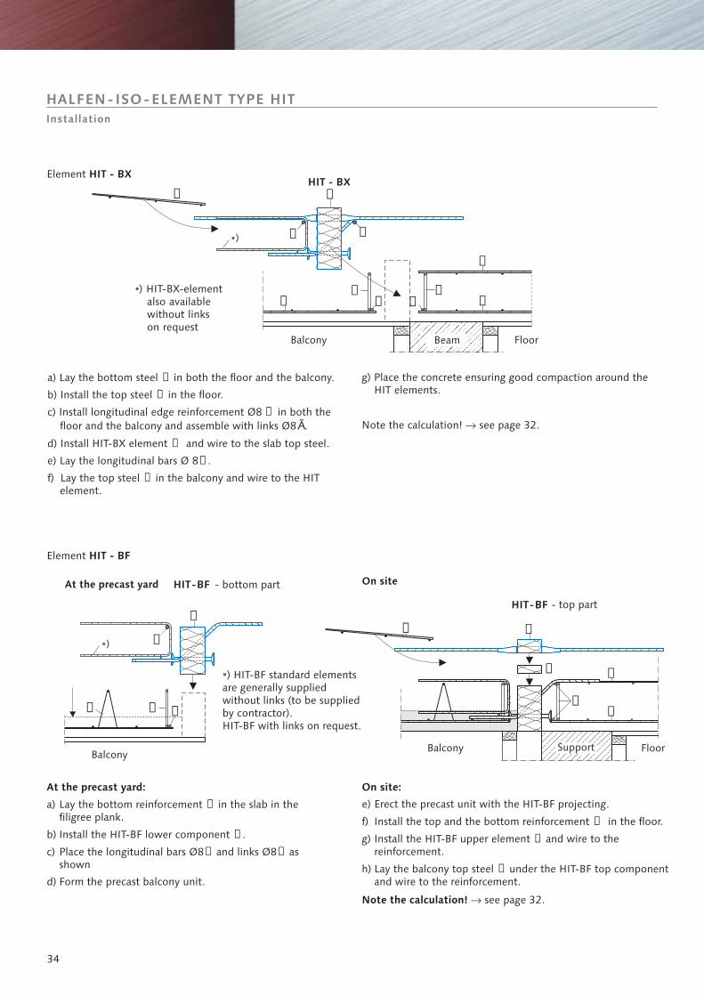
Element HIT - BX
a) Lay the bottom steel in both the floor and the balcony.
b) Install the top steel in the floor.
➀
➁
c) Install longitudinal edge reinforcement Ø8 in both thefloor and the balcony and assemble with links Ø8 .
d) Install HIT-BX element and wire to the slab top steel.
e) Lay the longitudinal bars Ø 8 .
f) Lay the top steel in the balcony and wire to the HITelement.
➂
➄
➅
➆
Ã
g) Place the concrete ensuring good compaction around theHIT elements.
Note the calculation! see page 32.�
At the precast yard:
a) Lay the bottom reinforcement in the slab in thefiligree plank.
b) Install the HIT-BF lower component .
d) Form the precast balcony unit.
➀
➁
c) Place the longitudinal bars Ø8 and links Ø8 asshown
➂ ➃
On site:
Note the calculation!
e) Erect the precast unit with the HIT-BF projecting.
f) Install the top and the bottom reinforcement in the floor.
g) Install the HIT-BF upper element and wire to thereinforcement.
h) Lay the balcony top steel under the HIT-BF top componentand wire to the reinforcement.
see page 32.
➄
➅
➆
�
Element HIT - BF
HALFEN-ISO-ELEMENT TYPE HITInstallation
*) HIT-BF standard elementsare generally suppliedwithout links (to be suppliedby contractor).HIT-BF with links on request.
35
�
�
�
�
�
�
�
CB
oC
Bo
dH
V HIT-BX/BF-HV 10HIT-BX/BF-HV 15
CD
ud D
d s
CD
o
3
3
20
CB
u
lü
��
�
�
�
�
HIT-BX/-BF
CB
o
dH
V
CD
ud Dd s
CB
u
CD
o
�
lü
�
�
l1
�
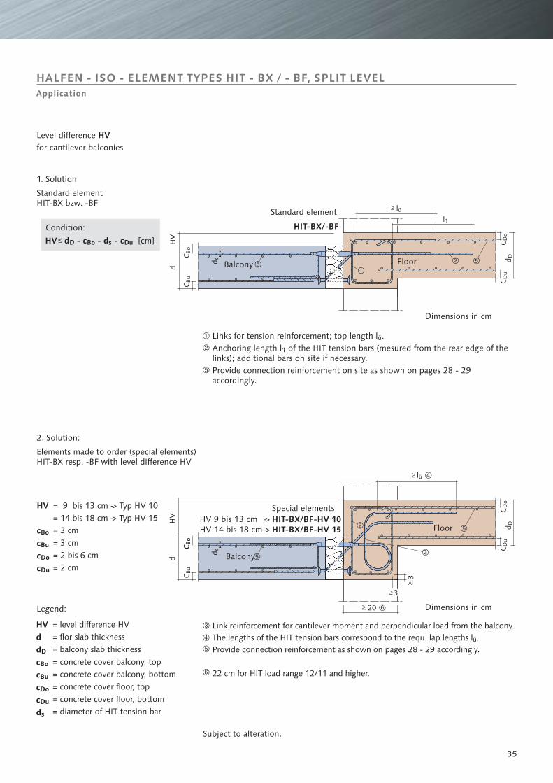
HALFEN - ISO - ELEMENT TYPES HIT - BX / - BF, SPLIT LEVELApplication
Balcony Floor
Balcony
Floor
Condition:
HV 9 bis 13 cmHV 14 bis 18 cm
Dimensions in cm
Dimensions in cm
Legend:
Standard element
Special elements
Links for tension reinforcement; top length l .
Provide connection reinforcement on site as shown on pages 28 - 29.
ü
Anchoring length l of the HIT tension bars (mesured from the rear edge of thelinks); additional bars on site if necessary.
accordingly
1
1. Solution
Standard elementHIT-BX bzw. -BF
2. Solution:
Elements made to order (special elements)HIT-BX resp. -BF with level difference HV
Link reinforcement for cantilever moment and perpendicular load from the balcony.
Provide connection reinforcement as shown on pages accordingly.
22 cm for HIT load range 12/11 and higher.
The lengths of the HIT tension bars correspond to the requ. lap lengths l .28 - 29
ü
Level differencefor cantilever balconies
HV
->->
= 9 bis 13 cm -> Typ HV 10= 14 bis 18 cm -> Typ HV 15= 3 cm= 3 cm= 2 bis 6 cm= 2 cm
Subject to alteration.
HV d - c - d - cD Bo s Du [cm]
= level difference HV= flor slab thickness= balcony slab thickness= concrete cover balcony, top= concrete cover balcony, bottom= concrete cover floor, top= concrete cover floor, bottom= diameter of HIT tension bar
HVddccccd
D
Bo
Bu
Do
Du
s
HV
cccc
Bo
Bu
Do
Du
36
HIT-BD
➁
➂
➇➆
➈
➅
➄
➃➀
➆
➁➄
➀➃ ➅
➂➂ HIT-BXHIT-BXHIT-BX-CORN.HIT-BX-CORN.H
IT-B
X-C
OR
NER
HIT
-BX
-CO
RN
ERBalcony 2L
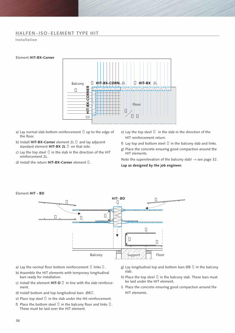
a) Lay normal slab bottom reinforcement up to the edge ofthe floor.
c) Lay the top steel in the slab in the direction of the HITreinforcement 2L.
➀
➁➂
➃
➄
b) Install element 2L and lay adjacentstandard element on that side.
d) Install the return element .
HIT-BX-CornerHIT-BX 2L
HIT-BX-Corner
e) Lay the top steel in the slab in the direction of the
HIT reinforcement return.
f) Lay top and bottom steel in the balcony slab and links.
g) Place the concrete ensuring good compaction around theHIT elements.
Note the superelevation of the balcony slab! see page 32.
➅
➆
Lap as designed by the job engineer.
�
Element HIT-BX-Corner
a) Lay the normal floor bottom reinforcement links .
c) Install the element in line with the slab reinforce-ment.
d) Install bottom and top longitudinal bars Ø8 .
e) Place top steel in the slab under the Hit reinforcement.
➀ ➁
➂
➃
➄
➅ ➆
b) Assemble the HIT elements with temporary longitudinalbars ready for installation.
f) Place the bottom steel in the balcony floor and links .These must be laid over the HIT element.
HIT-D
g) Lay longitudinal top and bottom bars Ø8 in the balconyslab.
h) Place the top steel in the balcony slab. These bars mustbe laid under the HIT element.
i) Place the concrete ensuring good compaction around the
HIT elements.
➇
➈
Support FloorBalcony
Element HIT - BD
Floor
2L
HALFEN-ISO-ELEMENT TYPE HITInstallation
HIT - BQ
HIT - ±BQ
37
➆ ➄➅
➂➇
➄ ➄➃ ➃
➀
➁
➅➄
➄ ➄➃ ➃
➀➅
➄➂➅
➄
➁➆
➇
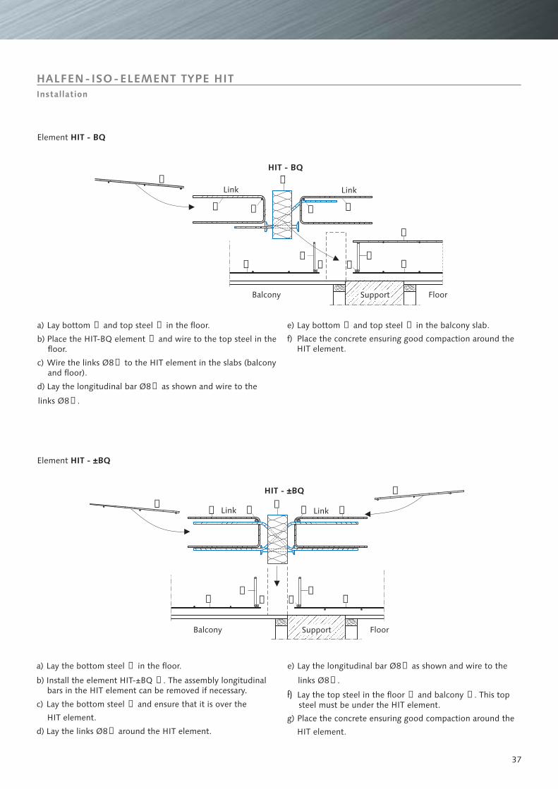
a) Lay the bottom steel in the floor.
b) Install the element HIT-±BQ The assembly longitudinalbars in the HIT element can be removed if necessary.
c) Lay the bottom steel and ensure that it is over the
HIT element.
d) Lay the links Ø8 around the HIT element.
➀
➁
➂
➃
.
e) Lay the longitudinal bar Ø8 as shown and wire to the
links Ø8
Lay the top steel in the floor and balcony This topsteel must be under the HIT element.
g) Place the concrete ensuring good compaction around the
HIT element.
➄
➅
➆ ➇
.
f) .
a) Lay bottom and top steel in the floor.
b) Place the HIT-BQ element and wire to the top steel in thefloor.
c) Wire the links Ø8 to the HIT element in the slabs (balconyand floor).
d) Lay the longitudinal bar Ø8 as shown and wire to the
links Ø8
➀ ➁
➂
➃
➄
➅ .
e) Lay bottom and top steel in the balcony slab.
f) Place the concrete ensuring good compaction around theHIT element.
➆ ➇
Element HIT - BQ
Element HIT - ±BQ
Support
Support
Floor
Floor
Link
Link
Link
Link
Balcony
HALFEN-ISO-ELEMENT TYPE HITInstallation
Balcony
38
➀➁
A A
➂
➀
➀➀
➀
➁➁
➁
➂➂
➂
➂
➀ ➁
➂
➀ ➁
➂
➀
➁
➀➁
A A
B B
➂➀
➀➁
B B
HIT
HIT➃
➃
➄
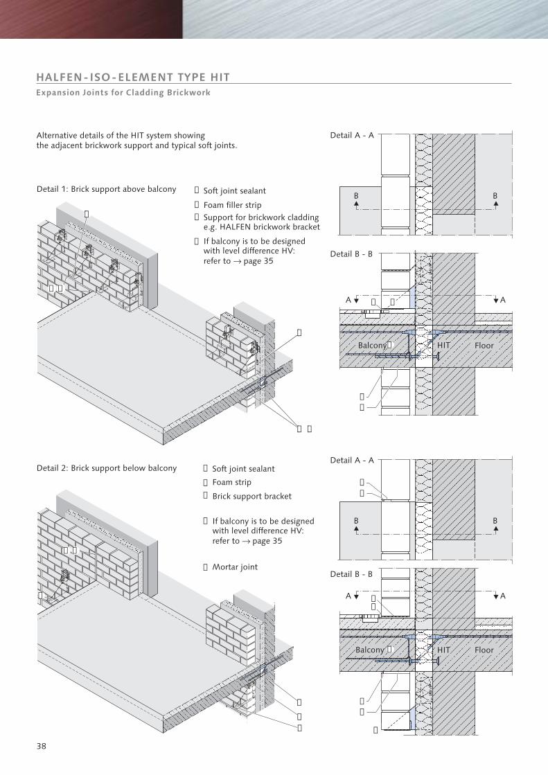
HALFEN-ISO-ELEMENT TYPE HITExpansion Joints for Cladding Brickwork
Balcony
Detail B - B
Floor
Detail 1: Brick support above balcony
Detail 2: Brick support below balcony
Alternative details of the HIT system showingthe adjacent brickwork support and typical soft joints.
Balcony
Detail B - B
Detail A - A
Detail A - A
Foam strip
Support for brickwork claddinge.g. HALFEN brickwork bracket
If balcony is to be designedwith level difference HV:refer to � page 35
Brick support bracket
Soft joint sealant
Foam filler strip
Soft joint sealant
Floor
If balcony is to be designedwith level difference HV:refer to � page 35
Mortar joint
➀
➁
➂
➀
➁
➂
➃
➃
➄
39
CONTACT
HALFEN-DEHA is represented in more than 35 countries worldwide. Please contact our Export ServiceCenter, if you wish to receiveinformation about the HALFEN-DEHA foreign representatives.
HALFEN-DEHA WORLDWIDE
HALFEN-DEHAVertriebsgesellschaft mbH-Export ServiceCenter-Liebigstr. 14D-40764 LangenfeldGERMANY
Please contact the Export ServiceCenter for:
Northern Europe Phone: +49 (0) 2173-970-842Fax: +49 (0) 2173-970-850
Eastern Europe Phone:
Middle Europe Phone: +49 (0) 2173-970-193Fax: +49 (0) 2173-970-849
South Europe Phone: +49 (0) 2173-970-839Fax: +49 (0) 2173-970-850
Asia / Australia Phone: +49 (0) 2173-970-842Fax: +49 (0) 2173-970-850
Arab Countries / Africa Phone:
North America Phone: +49 (0) 2173-970-193Fax: +49 (0) 2173-970-849
+49 (0) 2173-970-834Fax: +49 (0) 2173-970-850
+49 (0) 2173-970-842Fax: +49 (0) 2173-970-850
South America Phone: +49 (0) 2173-970-839Fax: +49 (0) 2173-970-850
Phone:Fax:
e-Mail:Internet:
+49 (0) 2173-970-831+49 (0) 2173-970-849
INTERNET
www.halfen-deha.com •Products •Catalogues •News •Download •Contact •Practice •About HALFEN-DEHA
NOTES REGARDING THIS CATALOGUE:
Technical and design changes reservedThe information in this publication is based on state-of-the-art technology at the time of publication. We reserve the right to maketechnical and design changes at any time. HALFEN-DEHA shall not accept liability for the accuracy of the information in this publicationor for any printing errors.
The HALFEN-DEHA Quality Management System is certified for the locations in Gemany and Switzerlandaccording to , Certificate No. QS-281 HH.DIN EN ISO 9001
RE-050-02/03
0.00
002
/03
HALFEN-DEHA Vertriebsgesellschaft mbH · Liebigstraße 14 · 40764 LangenfeldTelephone: + 49 (0) 2173-970-0 · Telefax: + 49 (0) 2173-970-849 · www.halfen-deha.com
© 2
003
HA
LFEN
-DEH
A V
ertr
iebs
gese
llsch
aft
mbH
,ap
plie
s al
so t
o co
pyin
g in
ext
ract
s