halfen anchor bolt systems - halfen-moment.com · 1 injection system hb-vmz gv 5 zz z zzz 2...
TRANSCRIPT
HALFEN ANCHOR BOLT SYSTEMS
CONCRETE
HB 10-E

2
Chemical Anchor Bolt Systems
Injection System - chemicalfor cracked and non-cracked concrete
1. Injection System HB -VMZ GV Zinc plated 5 - 8
2. Injection System HB -VMZ A4/HCR Stainless steel A4 / HCR 9 - 13
Chemical Anchor Boltfor non-cracked concrete
3. Chemical Anchor Bolt HB -V GV/FV Zinc plated / hot-dip galvanized 14 - 16
4. Chemical Anchor Bolt HB -V A4/HCR Stainless steel A4 / HCR 17 - 19
Injection System - chemicalfor non-cracked concrete + masonry
5. Injection System HB -VMU GV/A4 Zinc plated/stainless steel A4 20 - 28
Mechanical Heavy Duty Anchors
Wedge Anchorsfor cracked and non-cracked concrete
6. Wedge Anchor HB -BZ GV Zinc plated 30 - 32
7. Wedge Anchor HB -BZ A4/HCR Stainless steel A4 /HCR 33 - 36
Wedge Anchorsfor non-cracked concrete
8. Wedge Anchor HB -B GV/FV Zinc plated / hot-dip galvanized 37 - 40
9. Wedge Anchor HB -B A4/HCR Stainless steel A4 / HCR 40 - 42
Highload Anchorfor cracked and non-cracked concrete
10. Highload Anchor HB -SZ GV Zinc plated
43 - 45
Drop-in Anchorfor non-cracked concrete
11. Drop-in Anchor HB -E GV/A4/HCR Zinc plated / stainless steel A4 / HCR 46 - 50
Service
12. Fire Resistance Tables52 - 53
13. Load tables, for individual anchors and groups of anchors 54 - 71
Page
Table of contents
HALFEN ANCHOR BOLT SYSTEMS
All statements in this product range overview are subject to technical change without notice.
© 2010 HALFEN · HB 10 - E ⋅ www.halfen.com

3
European Technical Approval -Option 7
European Technical Approval
(ETA) with CE mark
National approval of the German
Institut für Bautechnik
DIN EN ISO 9001 certification
Factory Mutual (FM), U.S. appro-
val for installations of sprinkler
systems
Equates to VDS regulations for
pipeline fastenings of sprinkler
systems
Material sign for stainless steel
(A4 or HCR quality 1.4529)
Fire resistance tested in accor-
dance with DIN 4102-2, fire
resistance classes F30, F60, F90
and F120
Page
Cra
cked
con
cret
e
Non
-cra
cked
con
cret
e
Perf
orat
ed b
rickw
ork
Solid
bric
kwor
k
ETA
app
rova
l
DIB
T ap
prov
al
Fire
tes
ted
VdS
FM Stee
l, zi
nc p
late
d
Stee
l, ho
t-dip
gal
vani
zed
Stai
nles
s st
eel A
4
Stai
nles
s st
eel H
CR,
1.45
29
Cal
cula
tion
prog
ram
Chemical Anchor Bolt Systems
1 Injection System HB-VMZ GV 5
2 Injection System HB-VMZ A4 / HCR 9
3 Chemical Anchor Bolt HB-V GV/FV 14
4 Chemical Anchor Bolt HB-V A4 / HCR 17
5 Injection System HB-VMU GV/A4 20
Mechanical Heavy Duty Anchors
6 Wedge Anchor HB-BZ GV 30
7 Wedge Anchor HB-BZ A4 / HCR 33
8 Wedge Anchor HB-B GV/FV 37
9 Wedge Anchor HB-B A4 / HCR 40
10 Highload Anchor HB-SZ GV 43
11 Drop-in Anchor HB-E A4 /GV 46
Europäische Technische Zulassung -Option 7
Overview
HALFEN ANCHOR BOLT SYSTEMS
© 2010 HALFEN · HB 10 - E · www.halfen.com
4
Fire testetFire testet
Chemical Anchor Bolt SystemsHALFEN ANCHOR BOLTS
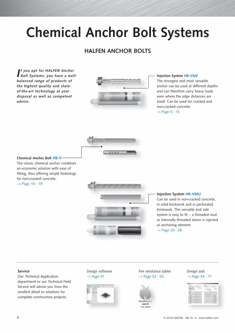
Chemical Anchor Bolt HB -VThe classic chemical anchor combines an economic solution with ease of fi tting, thus off ering simple fastenings for non-cracked concrete.→ Page 14 - 19
I f you opt for HALFEN Anchor Bolt Systems, you have a well-
balanced range of products of the highest quality and state-of-the-art technology at your disposal as well as competent advice.
Injection System HB -VMZThe strongest and most versatile anchor can be used at diff erent depths and can therefore carry heavy loads even where the edge distances are small. Can be used for cracked and non-cracked concrete.→ Page 5 - 13
Injection System HB -VMUCan be used in non-cracked concrete, in solid brickwork and in perforated brickwork. This versatile and safe system is easy to fi t – a threaded stud or internally threaded sleeve is injected as anchoring element. → Page 20 - 28
ServiceOur Technical Application department or our Technical Field Service will advise you from the smallest detail to solutions for complete construction projects.
Design software → Page 51
Fire resistance tables → Page 52 - 53
Design aids→ Page 54 - 71
© 2010 HALFEN · HB 10 - E ⋅ www.halfen.com
5
Anchor Stud HB -VMZ-A GV Table 1/2
Steel zinc plated; M 8 - M 12
Approved for cracked and non-cracked concrete
Designation Article number Drill holeØ x depth
mm
Setting depth
mm
Max.fixture thickness
tfixmm
Anchor length
mm
Thread
mm
Unit
pieces
Weight per package
kg
HB -VMZ-A 40 M8-15/65 GV 0432.380-00080 10 x 42 41 15 65 M8x22 10 0.30
HB -VMZ-A 50 M8-15/80 GV 0432.380-00027 10 x 55 52 15 80 M8x22 10 0.36
HB -VMZ-A 50 M8-30/95 GV 0432.380-00028 10 x 55 52 30 95 M8x31 10 0.41
HB -VMZ-A 50 M8-45/110 GV 0432.380-00029 10 x 55 52 45 110 M8x31 10 0.47
HB -VMZ-A 60 M10-10/85 GV 0432.380-00030 12 x 65 63 10 85 M10x18 10 0.61
HB -VMZ-A 60 M10-20/95 GV 0432.380-00031 12 x 65 63 20 95 M10x27 10 0.66
HB -VMZ-A 60 M10-30/105 GV 0432.380-00032 12 x 65 63 30 105 M10x27 10 0.72
HB -VMZ-A 60 M10-60/135 GV 0432.380-00033 12 x 65 63 60 135 M10x47 10 0.87
HB -VMZ-A 60 M10-100/175 GV 0432.380-00034 12 x 65 63 100 175 M10x57 10 1.10
HB -VMZ-A 75 M10-20/110 GV 0432.380-00081 12 x 80 78 20 110 M10x27 10 0.75
HB -VMZ-A 70 M12-25/115 GV 0432.380-00082 14 x 75 74 25 115 M12x36 10 1.20
HB -VMZ-A 80 M12-10/110 GV 0432.380-00035 14 x 85 84 10 110 M12x21 10 1.17
HB -VMZ-A 80 M12-25/125 GV 0432.380-00036 14 x 85 84 25 125 M12x36 10 1.28
HB -VMZ-A 80 M12-50/150 GV 0432.380-00037 14 x 85 84 50 150 M12x46 10 1.49
HB -VMZ-A 80 M12-100/200 GV 0432.380-00038 14 x 85 84 100 200 M12x71 10 1.93
HB -VMZ-A 80 M12-125/225 GV 0432.380-00039 14 x 85 84 125 225 M12x71 10 2.17
HB -VMZ-A 80 M12-165/265 GV 0432.380-00040 14 x 85 84 165 265 M12x71 10 2.57
HB -VMZ-A 95 M12-25/140 GV 0432.380-00083 14 x 100 99 25 140 M12x36 10 1.40
HB -VMZ-A 100 M12-25/145 GV 0432.380-00041 14 x 105 104 25 145 M12x36 10 1.46
HB -VMZ-A 100 M12-60/180 GV 0432.380-00042 14 x 105 104 60 180 M12x56 10 1.75
HB -VMZ-A 100 M12-100/220 GV 0432.380-00043 14 x 105 104 100 220 M12x61 10 2.12
HB -VMZ-A 110 M12-25/155 GV 0432.380-00084 14 x 115 114 25 155 M12x36 10 1.55
HB -VMZ-A 125 M12-25/170 GV 0432.380-00085 14 x 130 129 25 170 M12x36 10 1.75
Fire testet
ETA-07/02461
Injection System HB-VMZ zinc plated - for cracked and non-cracked concrete
CHEMICAL ANCHOR BOLT SYSTEMS
Description
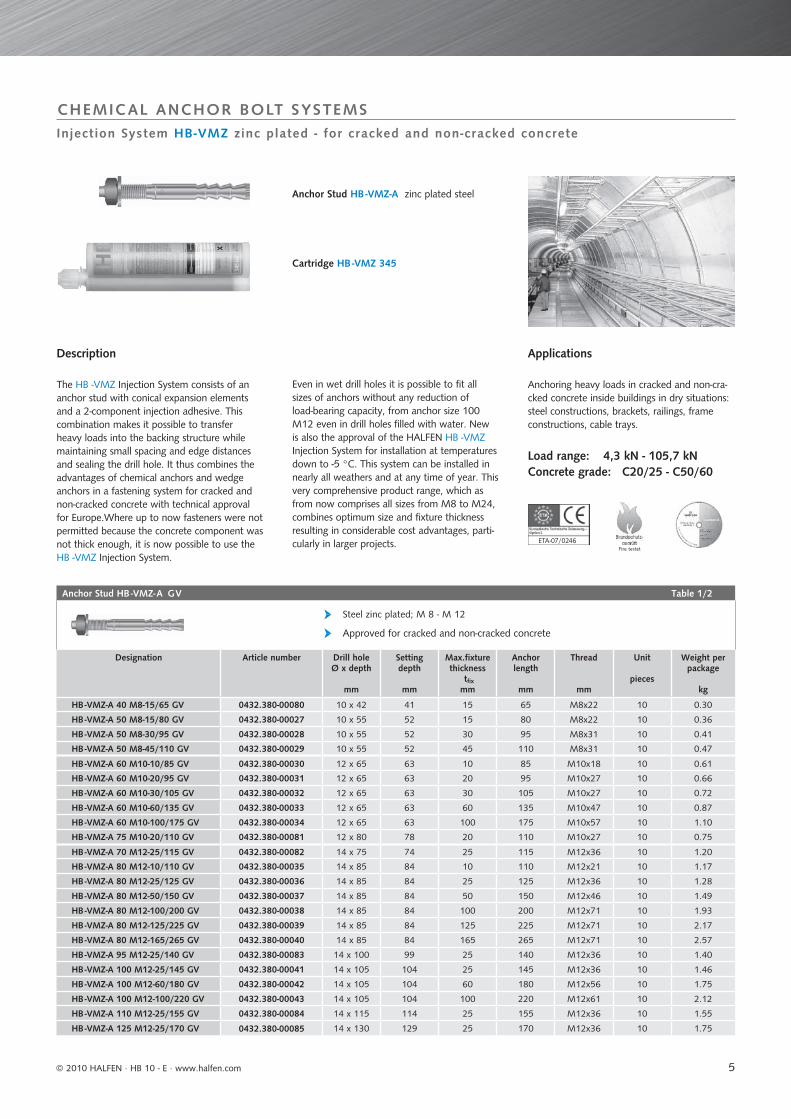
The HB -VMZ Injection System consists of an anchor stud with conical expansion elements and a 2-component injection adhesive. This combination makes it possible to transfer heavy loads into the backing structure while maintaining small spacing and edge distances and sealing the drill hole. It thus combines the advantages of chemical anchors and wedge anchors in a fastening system for cracked and non-cracked concrete with technical approval for Europe.Where up to now fasteners were not permitted because the concrete component was not thick enough, it is now possible to use the HB -VMZ Injection System.
Cartridge HB -VMZ 345
Anchor Stud HB -VMZ-A zinc plated steel
Even in wet drill holes it is possible to fit all sizes of anchors without any reduction of load-bearing capacity, from anchor size 100 M12 even in drill holes filled with water. New is also the approval of the HALFEN HB -VMZ Injection System for installation at temperatures down to -5 °C. This system can be installed in nearly all weathers and at any time of year. This very comprehensive product range, which as from now comprises all sizes from M8 to M24, combines optimum size and fixture thickness resulting in considerable cost advantages, parti-cularly in larger projects.
Applications
Anchoring heavy loads in cracked and non-cra-cked concrete inside buildings in dry situations: steel constructions, brackets, railings, frame constructions, cable trays.
Load range: 4,3 kN - 105,7 kNConcrete grade: C20/25 - C50/60
© 2010 HALFEN · HB 10 - E · www.halfen.com
6
Cleaning Brush HB -RB
Accessory for cleaning drill hole
Attachment for power drill
Designation Article number Drill-Ø
mm
Suitable for Unit
piece
Weight per piecekg
HB -RB 10 0433.040-00104 10 HB -VMZ M8 1 0.02
HB -RB 12 0433.040-00105 12 HB -VMZ M10 1 0.02
HB -RB 14 0433.040-00106 14 HB -VMZ M12 1 0.03
HB -RB 18 0433.040-00107 18 HB -VMZ M16 1 0.04
HB -RB 22 0433.040-00108 22 HB -VMZ 115 M20 1 0.05
HB -RB 24 0433.040-00113 24 HB -VMZ M20 1 0.05
HB -RB 26 0433.040-00109 26 HB -VMZ M24 1 0.06
Anchor Stud HB -VMZ-A GV Table 2/2
Steel zinc plated; M 16 - M 24
Approved for cracked and non-cracked concrete
Designation Article number
Drill holeØ x depth
mm
Setting depth
mm
Max.fixture thickness
tfixmm
Anchor length
mm
Thread
mm
Unit
pieces
Weight per package
kg
HB -VMZ-A 90 M16-30/145 GV 0432.380-00086 18 x 98 94 30 145 M16x44 10 2.20
HB -VMZ-A 105 M16-30/160 GV 0432.380-00087 18 x 113 109 30 160 M16x44 10 2.45
HB -VMZ-A 125 M16-30/180 GV 0432.380-00044 18 x 133 130 30 180 M16x44 10 2.78
HB -VMZ-A 125 M16-60/210 GV 0432.380-00045 18 x 133 130 60 210 M16x55 10 3.60
HB -VMZ-A 125 M16-100/250 GV 0432.380-00046 18 x 133 130 100 250 M16x65 10 4.23
HB -VMZ-A 125 M16-165/315 GV 0432.380-00047 18 x 133 130 165 315 M16x90 10 5.25
HB -VMZ-A 145 M16-30/200 GV 0432.380-00088 18 x 153 150 30 200 M16x44 10 3.70
HB -VMZ-A 115 M20-30/175 GV 0432.380-00089 22 x 120 120 30 175 M20x46 5 2.40
HB -VMZ-A 170 M20-20/225 LG GV 0432.380-00090 24 x 180 180 20 225 M20x41 5 3.40
HB -VMZ-A 170 M20-25/230 GV 0432.380-00049 24 x 180 180 25 230 M20x33 5 3.52
HB -VMZ-A 170 M20-50/255 GV 0432.380-00050 24 x 180 180 50 255 M20x46 5 3.83
HB -VMZ-A 170 M20-100/305 GV 0432.380-00051 24 x 180 180 100 305 M20x71 5 4.46
HB -VMZ-A 190 M20-50/275 GV 0432.380-00091 24 x 200 200 50 275 M20x46 5 4.20
HB -VMZ-A 200 M24-50/290 LG GV 0432.380-00092 26 x 215 212 50 290 M24x75 5 5.11
HB -VMZ-A 200 M24-50/290 GV 0432.380-00052 26 x 215 212 50 290 M24x50 5 5.11
HB -VMZ-A 200 M24-100/340 GV 0432.380-00053 26 x 215 212 100 340 M24x75 5 6.01
HB -VMZ-A 225 M24-50/315 GV 0432.380-00093 26 x 240 237 50 315 M24x50 5 6.50
Injection System HB -VMZ / Mixing Nozzle
Designation Article number Content
ml
Content of master
box cartridges
Weight per master box
kg
Weight per piecekg
Cartridge HB -VMZ 345 0433.040-00102 345 12 4.20 0.34
Mixing Nozzle HB -VM-X 0433.040-00039 - 12 0.12 0.01
Mixer Extension HB -VM-XE 0433.040-00076 - - - 0.01
Brush Gauge HB -VM-BL 0433.040-00103 - - - 0.02
Installation Wedge HB -VMZ-MK 0433.040-00116 - - - 0.01
Air gun / Blow-out Pump
Designation Article number
0433.040-
Suitable for drill hole Ø
mm
Unit
piece
Weight per
piecekg
HB-VM-AP 360 -00110 10-35 1 0.27
HB-VM-ABP -00111 22-26 1 1.00
HB-VM-ABP HB-VM-AP
Accessory for cleaning drill hole
Dispenser HB -VM-P
Designation Article number
0433.040-
Weight per piece kg
Dispenser HB-VM-P 345 -00077 0.87
Dispenser HB-VM-P 345 Profi -00078 1.20
The dispenser is also suitable for conventional silicone cartridges.
HB-VM-P
2-component adhesive, styrene free
Injection System HB-VMZ zinc plated - for cracked and non-cracked concrete
CHEMICAL ANCHOR BOLT SYSTEMS
One mixing nozzle is included with each cartridge Possible number of drill holes per cartridge , → p. 7 and 8 Single cartridges can also be supplied.
Version LG with thread to the surface of the concrete Further dimensions and thread lengths on request.
© 2010 HALFEN · HB 10 - E ⋅ www.halfen.com

7
Extract from Admissible Service Conditions of ETA-07/0246 (M 8 - M 12) Table 1/2
Loads and performance data Injection System HB -VMZ
40 M
8
50 M
8
60 M
10
75 M
10
70 M
12
80 M
12
95 M
12
100
M 1
2
110
M 1
2
125
M 1
2
cracked concreteC20/25 App. N [kN] 4.3 6.1 8.0 11.1 10.0 12.3 15.9 17.1 19.8 24.0
C25/30 App. N [kN] 4.8 6.7 8.8 11.9 11.0 13.5 17.5 18.9 21.8 26.4
Approved loads, tension C30/37 App. N [kN] 5.3 7.4 9.7 11.9 12.2 15.0 19.4 20.9 24.1 27.1
C40/50 App. N [kN] 6.1 8.5 11.2 11.9 14.2 17.3 22.4 24.2 27.1 27.1
C50/60 App. N [kN] 6.7 8.6 11.9 11.9 15.6 19.0 24.6 26.6 27.1 27.1
non-cracked concrete
Approved loads, tension C20/25 App. N [kN] 4.3 8.5 11.2 11.9 14.1 17.2 19.0 24.0 23.8 23.8
C25/30 App. N [kN] 4.7 8.6 11.9 11.9 15.5 18.9 21.0 26.4 26.2 26.2
Approved loads, tension C30/37 App. N [kN] 5.2 8.6 11.9 11.9 17.1 21.0 23.2 27.1 27.1 27.1
C40/50 App. N [kN] 6.0 8.6 11.9 11.9 19.8 24.2 25.7 27.1 27.1 27.1
C50/60 App. N [kN] 6.6 8.6 11.9 11.9 21.8 25.7 25.7 27.1 27.1 27.1
cracked and non-cracked concreteApproved loads, shear C20/25 App. V [kN] 8.0 8.0 12.0 12.0 19.4 19.4 19.4 19.4 19.4 19.4
Approved loads, shear Version LG C20/25 App. V [kN] 8.0 8.0 12.0 12.0 19.4 19.4 19.4 19.4 19.4 19.4
Approved bending moment App. M [Nm] 17.1 17.1 34.3 34.3 60.0 60.0 60.0 60.0 60.0 60.0
Spacing and edge distancesEffective anchorage depth hef [mm] 40 50 60 75 70 80 95 100 110 125
Characteristic spacing scr,N [mm] 120 150 180 225 210 240 285 300 330 375
Characteristic edge distance ccr,N [mm] 60 75 90 112.5 105 120 142.5 150 165 187.5
Standard thickness of building component - cracked concreteMinimum thickness of building component hmin [mm] 100 100 120 150 140 160 190 200 220 250
Minimum spacing/for egde distance c smin / c [mm] 40/40 40/40 50/55 50/55 55/90 55/80 55/80 55/80 55/80 55/80
Minimum edge distance/for spacing s cmin / s [mm] 40/40 40/40 50/55 50/55 55/90 55/80 55/80 55/80 55/80 55/80
Reduced thickness of building component - cracked concreteMinimum thickness of building component hmin, red [mm] 80 80 100 100 100 110 130 130 140 160
Minimum spacing/for egde distance c smin / c [mm] 40/40 40/40 50/120 50/120 70/100 60/120 60/120 55/120 55/120 55/120
Minimum edge distance/for spacing s cmin / s [mm] 40/40 40/40 50/120 50/120 75/150 70/160 70/160 60/140 60/140 60/140
Installation parametersDrill hole diameter do [mm] 10 10 12 12 14 14 14 14 14 14
Diameter of clearance hole in the fixture df [mm] 9 9 12 12 14 14 14 14 14 14
Depth of drill hole ho [mm] 42 55 65 80 75 85 100 105 115 130
Installation torque Tinst [Nm] 10 10 20 20 40 40 40 40 40 40
Width across nut SW [mm] 13 13 17 17 19 19 19 19 19 19
Drill hole fill quantity, scale on cartridge [mm] 2 3 4 4 4 5 6 6 6 6Adhesive required per drill hole [ml] 3.4 4.1 6.1 7.0 6.8 8.6 9.0 9.2 9.4 9.6
Drill holes per cartridges VMZ 345 [piece] 88 73 49 43 44 34 33 32 32 31
Processing and curing timesTemperature (°C)in the drill hole
Processing time Curing time
dry concrete damp concrete
Minutes Minutes Minutes≥ +40 °C 1.4 15 30≥ +35 °C 2 20 40≥ +30 °C 4 25 50≥ +20 °C 6 45 90≥ +10 °C 12 80 160≥ +5 °C 20 120 240≥ 0 °C 45 180 360≥ -5 °C 90 330 660
M
h0
Tinst
d0
hef
≥ hmin
tfi x
ETA-07/02461
CHEMICAL ANCHOR BOLT SYSTEMS
Ask for our easy to operate design software on CD-ROM or download from www.halfen.com
Extract from Admissible Service Conditions of ETA-07/0246 (M 8 - M 12)Approved loads for anchors without influence of spacing and edge distance.Total safety factor as per ETAG included (γM and γF)
Injection System HB-VMZ zinc plated - for cracked and non-cracked concrete
© 2010 HALFEN · HB 10 - E · www.halfen.com

8
Extract from Admissible Service Conditions of ETA-07/0246 (M 16 - M 24) Table 2/2
Loads and performance data Injection System HB -VMZ
90 M
16
105
M16
125
M 1
6
145
M 1
6
115
M 2
0
170
M 2
017
0 M
20
LG
190
M 2
019
0 M
20
LG
200
M 2
420
0 M
24
LG
225
M 2
422
5 M
24
LG
cracked concrete
Approved loads, tension C20/25 App. N [kN] 14.6 18.4 24.0 29.9 21.1 38.0 44.9 48.5 57.9
C25/30 App. N [kN] 16.1 20.3 26.4 32.9 23.3 41.8 49.4 53.3 63.6
C30/37 App. N [kN] 17.9 22.5 29.2 36.5 25.8 46.4 54.8 59.2 70.6
C40/50 App. N [kN] 20.6 26.0 33.8 42.2 29.8 53.6 63.3 68.4 81.6
C50/60 App. N [kN] 22.7 28.8 37.1 46.4 32.8 58.9 69.6 75.2 89.7
non-cracked concrete
Approved loads, tension C20/25 App. N [kN] 20.5 25.8 33.5 35.7 29.6 53.2 62.9 67.9 81.0
C25/30 App. N [kN] 22.5 28.4 36.9 39.3 32.6 58.5 69.1 74.7 89.1
C30/37 App. N [kN] 25.0 31.5 40.9 43.6 36.1 64.9 76.7 82.8 98.8
C40/50 App. N [kN] 28.9 36.4 47.3 50.4 41.7 75.0 88.6 95.7 105.7
C50/60 App. N [kN] 31.8 40.0 52.0 52.9 45.9 82.5 89.5 105.2 105.7
cracked and non-cracked concreteApproved loads, shear C20/25 App. V [kN] 29.3 36.0 36.0 36.0 35.7 76.0 85.1 97.0 101.7
Approved loads, shear Version LG C20/25 App. V [kN] 29.3 36.0 36.0 36.0 35.7 56.0 56.0 80.6 80.6
Approved bending moment App. M [Nm] 152.0 152.0 152.0 152.0 200.0 296.6 296.6 512.0 512.0
Spacing and edge distancesEffective anchorage depth hef [mm] 90 105 125 145 115 170 190 200 225
Characteristic spacing scr.N [mm] 270 315 375 435 345 510 570 600 675
Characteristic edge distance ccr.N [mm] 135 157.5 187.5 217.5 172.5 255 285 300 337.5
Standard thickness of building component - cracked concreteMinimum thickness of building component hmin [mm] 180 200 250 290 230 340 380 400 450
Minimum spacing/for egde distance c smin / c [mm] 70/120 70/120 70/90 70/90 80/80 90/90 90/90 100/100 100/100
Minimum edge distance/for spacing s cmin / s [mm] 70/130 70/130 70/110 70/110 80/80 90/90 90/90 100/100 100/100
Reduced thickness of building component - cracked concreteMinimum thickness of building component hmin. red [mm] 130 150 160 180 160 220 240 260 290
Minimum spacing/for egde distance c smin / c [mm] 70/140 70/120 70/140 70/140 80/80 95/95 95/95 105/105 105/105
Minimum edge distance/for spacing s cmin / s [mm] 70/150 70/150 70/140 70/140 80/80 95/95 95/95 105/105 105/105
Installation parametersDrill hole diameter do [mm] 18 18 18 18 22 24 24 26 26
Diameter of clearance hole in the fixture df [mm] 18 18 18 18 22 24 (22) 24 (22) 26 26
Depth of drill hole ho [mm] 98 113 133 153 120 180 200 215 240
Installation torque Tinst [Nm] 60 60 60 60 80 80 80 120 120
Width across nut SW [mm] 24 24 24 24 30 30 30 36 36
Drill hole fill quantity, scale on cartridge [mm] 7 8 9 9 12 17 19 21 23Adhesive required per drill hole [ml] 11.1 12.6 14.5 15.8 20.8 30.1 32.2 36.6 41.3
Drill holes per cartridges VMZ 345 [piece] 27 23 20 19 14 10 9 8 7
s
cc
h
s
45min
+20 °C
Nm
90°
ETA-07/02461
CHEMICAL ANCHOR BOLT SYSTEMS
Values in brackets apply to version LG. Approved values for the temperature range -40°C to +120°C see ETA 07/0246.Ask for our easy to operate design software on CD-ROM or download from www.halfen.com.
Extract from Admissible Service Conditions of ETA-07/0246 (M 16 - M 24)Approved loads for anchors without influence of spacing and edge distance in the temperature range -40°C to +80°C .Total safety factor as per ETAG included (γM and γF)
Injection System HB-VMZ zinc plated - for cracked and non-cracked concrete
Installation
Spacing and edge distance:
© 2010 HALFEN · HB 10 - E ⋅ www.halfen.com

9
Anchor stud HB -VMZ-A A4 Table 1/2
Stainless steel A4; M 8 - M 12
Approved for cracked and non-cracked concrete
Designation Article number Drill holeØ x depth
mm
Setting depthmm
Max.fixture thickness tfix
mm
Anchor lengthmm
Thread
mm
Unit
piece
Weight per package
kg
HB -VMZ-A 40 M8-15/65 A4 0432.380-00060 10 x 42 41 15 65 M8x22 10 0.30HB -VMZ-A 50 M8-15/80 A4 0432.380-00001 10 x 55 52 15 80 M8x22 10 0.36HB -VMZ-A 50 M8-30/95 A4 0432.380-00002 10 x 55 52 30 95 M8x31 10 0.41HB -VMZ-A 50 M8-45/110 A4 0432.380-00003 10 x 55 52 45 110 M8x31 10 0.47HB -VMZ-A 60 M10-10/85 A4 0432.380-00004 12 x 65 63 10 85 M10x18 10 0.61HB -VMZ-A 60 M10-20/95 A4 0432.380-00005 12 x 65 63 20 95 M10x27 10 0.66HB -VMZ-A 60 M10-30/105 A4 0432.380-00006 12 x 65 63 30 105 M10x27 10 0.72HB -VMZ-A 60 M10-60/135 A4 0432.380-00007 12 x 65 63 60 135 M10x47 10 0.87HB -VMZ-A 60 M10-100/175 A4 0432.380-00008 12 x 65 63 100 175 M10x57 10 1.10HB -VMZ-A 75 M10-20/110 A4 0432.380-00061 12 x 80 78 20 110 M10x27 10 0.75HB -VMZ-A 75 M10-40/130 A4 0432.380-00094 12 x 80 78 40 130 M10x47 10 0.86HB -VMZ-A 70 M12-25/115 A4 0432.380-00062 14 x 75 74 25 115 M12x36 10 1.20HB -VMZ-A 70 M12-40/130 A4 0432.380-00095 14 x 75 74 40 130 M12x36 10 1.33HB -VMZ-A 80 M12-10/110 A4 0432.380-00009 14 x 85 84 10 110 M12x21 10 1.17HB -VMZ-A 80 M12-25/125 A4 0432.380-00010 14 x 85 84 25 125 M12x36 10 1.28HB -VMZ-A 80 M12-50/150 A4 0432.380-00011 14 x 85 84 50 150 M12x46 10 1.49HB -VMZ-A 80 M12-60/160 A4 0432.380-00096 14 x 85 84 60 160 M12x56 10 1.56HB -VMZ-A 80 M12-100/200 A4 0432.380-00012 14 x 85 84 100 200 M12x71 10 1.93HB -VMZ-A 80 M12-125/225 A4 0432.380-00013 14 x 85 84 125 225 M12x71 10 2.17HB -VMZ-A 80 M12-165/265 A4 0432.380-00014 14 x 85 84 165 265 M12x71 10 2.57HB -VMZ-A 95 M12-25/140 A4 0432.380-00063 14 x 100 99 25 140 M12x36 10 1.40HB -VMZ-A 100 M12-25/145 A4 0432.380-00015 14 x 105 104 25 145 M12x36 10 1.46HB -VMZ-A 100 M12-60/180 A4 0432.380-00016 14 x 105 104 60 180 M12x56 10 1.75HB -VMZ-A 100 M12-100/220 A4 0432.380-00017 14 x 105 104 100 220 M12x61 10 2.12HB -VMZ-A 110 M12-25/155 A4 0432.380-00064 14 x 115 114 25 155 M12x36 10 1.55HB -VMZ-A 125 M12-25/170 A4 0432.380-00065 14 x 130 129 25 170 M12x36 10 1.75HB -VMZ-A 125 M12-60/205 A4 0432.380-00097 14 x 130 129 60 205 M12x56 10 2.11
Suitable for fixing HALFEN Support Brackets.=
Preference anchor, HALFEN applications=
Fire testetETA-07/02561
Injection System HB-VMZ A4 - for cracked and non-cracked concrete
CHEMICAL ANCHOR BOLT SYSTEMS
Cartridge HB -VMZ 345
Anchor Stud HB -VMZ-A A4
Description
The HB -VMZ Injection System consists of an anchor stud with conical expansion elements and a 2-component injection adhesive. This combination makes it possible to transfer heavy loads into the backing structure while maintaining small spacing and edge distances and sealing the drill hole. It thus combines the advantages of chemical anchors and wedge anchors in a fastening system for cracked and non-cracked concrete with technical approval for Europe. Where up to now fasteners were not permitted because the concrete component was not thick enough, it is now possible to use the HB -VMZ Injection System. Even in wet drill holes it is possible to fit all sizes of anchors without any reduction of load bearing capacity, from anchor size 100 M12 even in drill holes filled with water. New is also the approval of the HALFEN HB -VMZ Injection System for
installation at temperatures down to -5 °C.Consequently, this system can be installed innearly all weathers and at any time of year.This very comprehensive product range, whichas from now comprises twelve new sizes fromM8 to M24, combines optimum size andfixture thickness, resulting in considerable costadvantages, particularly in larger projects.
Applications
Anchoring heavy loads in cracked and non-cracked concrete inside buildings and in theopen or in damp rooms without aggressiveconditions. Steel constructions, brackets,railings, façade constructions, bracket anchors,cable trays, fastenings for bridge railings inaccordance with specification drawingGEL 14 (HB -VMZ 70 M12-40/130 A4)and GEL 33 (HB -VMZ 90 M16-60/175 A4).
Load range: 4,3 kN - 92,4 kNConcrete grade: C20/25 - C50/60
© 2010 HALFEN · HB 10 - E · www.halfen.com

10
Anchor stud HB -VMZ-A A4 Table 2/2
Stainless steel A4; M 16 - M 24
Approved for cracked and non-cracked concrete
Designation Article number Drill holeØ x depth
mm
Setting depth
mm
Max.fixture thickness tfix
mm
Anchorlength
mm
Thread
mm
Unit
piece
Weight per package
kg
HB -VMZ-A 90 M16-30/145 A4 0432.380-00066 18 x 98 94 30 145 M16x44 10 2.20
HB -VMZ-A 90 M16-45/160 A4 0432.380-00067 18 x 98 94 45 160 M16x44 10 2.78
HB -VMZ-A 90 M16-60/175 A4 0432.380-00098 18 x 98 94 60 190 M16x50 10 3.08
HB -VMZ-A 105 M16-30/160 A4 0432.380-00068 18 x 113 109 30 160 M16x44 10 2.45
HB -VMZ-A 105 M16-60/190 A4 0432.380-00099 18 x 113 109 60 190 M16x50 10 2.90
HB -VMZ-A 125 M16-30/180 A4 0432.380-00018 18 x 133 130 30 180 M16x44 10 2.78
HB -VMZ-A 125 M16-60/210 A4 0432.380-00019 18 x 133 130 60 210 M16x55 10 3.60
HB -VMZ-A 125 M16-100/250 A4 0432.380-00020 18 x 133 130 100 250 M16x65 10 4.23
HB -VMZ-A 125 M16-165/315 A4 0432.380-00021 18 x 133 130 165 315 M16x90 10 5.25
HB -VMZ-A 145 M16-30/200 A4 0432.380-00069 18 x 153 150 30 200 M16x44 10 3.70
HB -VMZ-A 115 M20-30/175 A4 0432.380-00070 22 x 120 120 30 175 M20x46 5 2.40
HB -VMZ-A 170 M20-20/225 LG A4 0432.380-00071 24 x 180 180 20 225 M20x41 5 3.40
HB -VMZ-A 170 M20-25/230 A4 0432.380-00022 24 x 180 180 25 230 M20x33 5 3.52
HB -VMZ-A 170 M20-50/255 A4 0432.380-00023 24 x 180 180 50 255 M20x46 5 3.83
HB -VMZ-A 170 M20-100/305 A4 0432.380-00024 24 x 180 180 100 305 M20x71 5 4.46
HB -VMZ-A 190 M20-50/275 A4 0432.380-00072 24 x 200 200 50 275 M20x46 5 4.20
HB -VMZ-A 200 M24-50/290 LG A4 0432.380-00073 26 x 215 212 50 290 M24x75 5 5.11
HB -VMZ-A 200 M24-50/290 A4 0432.380-00025 26 x 215 212 50 290 M24x50 5 5.11
HB -VMZ-A 200 M24-100/340 A4 0432.380-00026 26 x 215 212 100 340 M24x75 5 6.01
HB -VMZ-A 225 M24-50/315 A4 0432.380-00074 26 x 240 237 50 315 M24x50 5 6.50
Cleaning Brush HB -RB
Accessory for cleaning drill hole
Attachment for power drill
Designation Article number
0433.040-
Drill-Ø
mm
Suitable for Unit
piece
Weight per piecekg
HB -RB 10 -00104 10 HB -VMZ M8 1 0.02
HB -RB 12 -00105 12 HB -VMZ M10 1 0.02
HB -RB 14 -00106 14 HB -VMZ M12 1 0.03
HB -RB 18 -00107 18 HB -VMZ M16 1 0.04
HB -RB 22 -00108 22 HB -VMZ 115 M20 1 0.05
HB -RB 24 -00113 24 HB -VMZ M20 1 0.05
HB -RB 26 -00109 26 HB -VMZ M24 1 0.06
Dispenser HB -VM-P
Designation Article number
0433.040-
Weight per piece kg
Dispenser HB-VM-P 345 -00077 0.87
Dispenser HB-VM-P 345 Profi -00078 1.20
Dispenser is also suitable for conventional silicone cartridges.
Air gun / Blow-out Pump
Designation Article number
0433.040-
Suitable for holes
Ømm
Unit
piece
Weight per
piecekg
HB-VM-AP 360 -00110 10-35 1 0.27
HB-VM-ABP -00111 22 - 26 1 1.00
HB-VM-ABP HB-VM-AP
Accessory for cleaning drill hole
Injection System HB -VMZ / Mixing Nozzle
Designation Article number Content
ml
Content of master
box cartridges
Weight per master box
kg
Weight per piecekg
Cartridge HB -VMZ 345 0433.040-00102 345 12 4.20 0.34
Mixing Nozzle HB -VM-X 0433.040-00039 - 12 0.12 0.01
Mixer Extension HB -VM-XE 0433.040.00076 - - - 0.01
Brush gauge HB -VM-BL 0433.040.00103 - - - 0.02
Installation Wedge HB -VMZ-MK 0433.040-00116 - - - 0.01
2-component adhesive, styrene free
Suitable for fixing HALFEN Support Brackets.=
Preference anchor, HALFEN applications=
Injection System HB-VMZ A4 - for cracked and non-cracked concrete
CHEMICAL ANCHOR BOLT SYSTEMS
Version LG with thread to the surface of the concrete. Further dimensions and thread lengths on request.
One mixing nozzle is included with each cartridge Possible number of drill holes per cartridge, → p. 11 and 12
Single cartridges can also be supplied.
HB-VM-P
© 2010 HALFEN · HB 10 - E ⋅ www.halfen.com
11
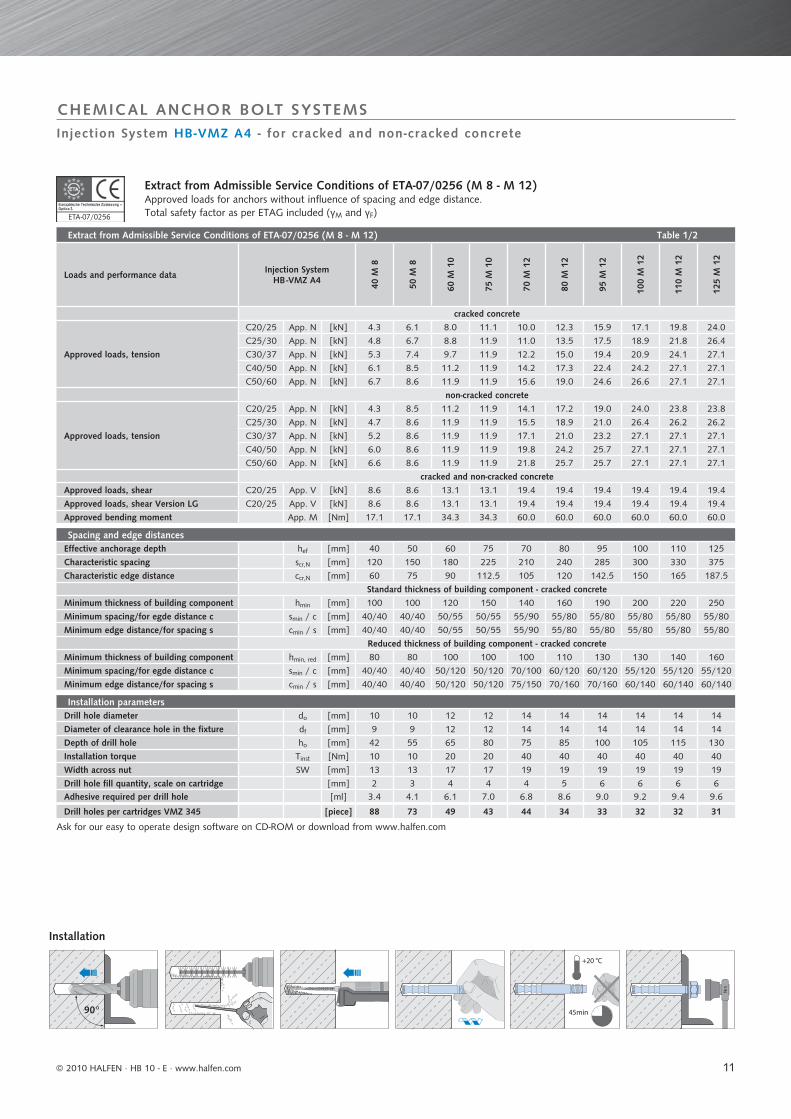
Extract from Admissible Service Conditions of ETA-07/0256 (M 8 - M 12) Table 1/2
Loads and performance data Injection System HB -VMZ A4
40 M
8
50 M
8
60 M
10
75 M
10
70 M
12
80 M
12
95 M
12
100
M 1
2
110
M 1
2
125
M 1
2
cracked concrete
Approved loads, tension
C20/25 App. N [kN] 4.3 6.1 8.0 11.1 10.0 12.3 15.9 17.1 19.8 24.0
C25/30 App. N [kN] 4.8 6.7 8.8 11.9 11.0 13.5 17.5 18.9 21.8 26.4
C30/37 App. N [kN] 5.3 7.4 9.7 11.9 12.2 15.0 19.4 20.9 24.1 27.1
C40/50 App. N [kN] 6.1 8.5 11.2 11.9 14.2 17.3 22.4 24.2 27.1 27.1
C50/60 App. N [kN] 6.7 8.6 11.9 11.9 15.6 19.0 24.6 26.6 27.1 27.1
non-cracked concrete
Approved loads, tension
C20/25 App. N [kN] 4.3 8.5 11.2 11.9 14.1 17.2 19.0 24.0 23.8 23.8
C25/30 App. N [kN] 4.7 8.6 11.9 11.9 15.5 18.9 21.0 26.4 26.2 26.2
C30/37 App. N [kN] 5.2 8.6 11.9 11.9 17.1 21.0 23.2 27.1 27.1 27.1
C40/50 App. N [kN] 6.0 8.6 11.9 11.9 19.8 24.2 25.7 27.1 27.1 27.1
C50/60 App. N [kN] 6.6 8.6 11.9 11.9 21.8 25.7 25.7 27.1 27.1 27.1
cracked and non-cracked concreteApproved loads, shear C20/25 App. V [kN] 8.6 8.6 13.1 13.1 19.4 19.4 19.4 19.4 19.4 19.4
Approved loads, shear Version LG C20/25 App. V [kN] 8.6 8.6 13.1 13.1 19.4 19.4 19.4 19.4 19.4 19.4
Approved bending moment App. M [Nm] 17.1 17.1 34.3 34.3 60.0 60.0 60.0 60.0 60.0 60.0
Spacing and edge distancesEffective anchorage depth hef [mm] 40 50 60 75 70 80 95 100 110 125
Characteristic spacing scr,N [mm] 120 150 180 225 210 240 285 300 330 375
Characteristic edge distance ccr,N [mm] 60 75 90 112.5 105 120 142.5 150 165 187.5
Standard thickness of building component - cracked concreteMinimum thickness of building component hmin [mm] 100 100 120 150 140 160 190 200 220 250
Minimum spacing/for egde distance c smin / c [mm] 40/40 40/40 50/55 50/55 55/90 55/80 55/80 55/80 55/80 55/80
Minimum edge distance/for spacing s cmin / s [mm] 40/40 40/40 50/55 50/55 55/90 55/80 55/80 55/80 55/80 55/80
Reduced thickness of building component - cracked concreteMinimum thickness of building component hmin, red [mm] 80 80 100 100 100 110 130 130 140 160
Minimum spacing/for egde distance c smin / c [mm] 40/40 40/40 50/120 50/120 70/100 60/120 60/120 55/120 55/120 55/120
Minimum edge distance/for spacing s cmin / s [mm] 40/40 40/40 50/120 50/120 75/150 70/160 70/160 60/140 60/140 60/140
Installation parametersDrill hole diameter do [mm] 10 10 12 12 14 14 14 14 14 14
Diameter of clearance hole in the fixture df [mm] 9 9 12 12 14 14 14 14 14 14
Depth of drill hole ho [mm] 42 55 65 80 75 85 100 105 115 130
Installation torque Tinst [Nm] 10 10 20 20 40 40 40 40 40 40
Width across nut SW [mm] 13 13 17 17 19 19 19 19 19 19
Drill hole fill quantity, scale on cartridge [mm] 2 3 4 4 4 5 6 6 6 6Adhesive required per drill hole [ml] 3.4 4.1 6.1 7.0 6.8 8.6 9.0 9.2 9.4 9.6
Drill holes per cartridges VMZ 345 [piece] 88 73 49 43 44 34 33 32 32 31
45min
+20 °C
Nm
90°
ETA-07/02561
CHEMICAL ANCHOR BOLT SYSTEMS
Ask for our easy to operate design software on CD-ROM or download from www.halfen.com
Extract from Admissible Service Conditions of ETA-07/0256 (M 8 - M 12)Approved loads for anchors without influence of spacing and edge distance.Total safety factor as per ETAG included (γM and γF)
Installation
Injection System HB-VMZ A4 - for cracked and non-cracked concrete
© 2010 HALFEN · HB 10 - E · www.halfen.com
12
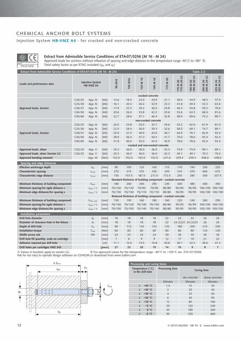
Extract from Admissible Service Conditions of ETA-07/0256 (M 16 - M 24) Table 2/2
Loads and performance data Injection System HB -VMZ A4
90 M
16
105
M16
125
M 1
6
145
M 1
6
115
M 2
0
170
M 2
017
0 M
20
LG
190
M 2
019
0 M
20
LG
200
M 2
420
0 M
24
LG
225
M 2
422
5 M
24
LG
cracked concrete
Approved loads, tension
C20/25 App. N [kN] 14.6 18.4 24.0 29.9 21.1 38.0 44.9 48.5 57.9
C25/30 App. N [kN] 16.1 20.3 26.4 32.9 23.3 41.8 49.4 53.3 63.6
C30/37 App. N [kN] 17.9 22.5 29.2 36.5 25.8 46.4 54.8 59.2 70.6
C40/50 App. N [kN] 20.6 26.0 33.8 42.2 29.8 53.6 63.3 68.4 81.6
C50/60 App. N [kN] 22.7 28.6 37.1 46.4 32.8 58.9 69.6 75.2 89.7
non-cracked concrete
Approved loads, tension
C20/25 App. N [kN] 20.5 25.8 33.5 35.7 29.6 53.2 62.9 67.9 81.0
C25/30 App. N [kN] 22.5 28.4 36.9 39.3 32.6 58.5 69.1 74.7 89.1
C30/37 App. N [kN] 25.0 31.5 40.9 43.6 36.1 64.9 76.7 82.8 92.4
C40/50 App. N [kN] 28.9 36.4 47.3 50.4 41.7 75.0 78.6 92.4 92.4
C50/60 App. N [kN] 31.8 40.0 52.0 52.9 45.9 78.6 78.6 92.4 92.4
cracked and non-cracked concreteApproved loads, shear C20/25 App. V [kN] 29.3 36.0 36.0 36.0 42.3 74.9 74.9 89.1 89.1
Approved loads, shear Version LG C20/25 App. V [kN] 29.3 36.0 36.0 36.0 42.3 49.1 49.1 70.3 70.3
Approved bending moment App. M [Nm] 152.0 152.0 152.0 152.0 231.6 259.4 259.4 448.0 448.0
Spacing and edge distancesEffective anchorage depth hef [mm] 90 105 125 145 115 170 190 200 225
Characteristic spacing scr,N [mm] 270 315 375 435 345 510 570 600 675
Characteristic edge distance ccr,N [mm] 135 157.5 187.5 217.5 172.5 255 285 300 337.5
Standard thickness of building component - cracked concreteMinimum thickness of building component hmin [mm] 180 200 250 290 230 340 380 400 450
Minimum spacing/for egde distance c smin / c [mm] 70/120 70/120 70/90 70/90 80/80 90/90 90/90 100/100 100/100
Minimum edge distance/for spacing s cmin / s [mm] 70/130 70/130 70/110 70/110 80/80 90/90 90/90 100/100 100/100
Reduced thickness of building component - cracked concreteMinimum thickness of building component hmin, red [mm] 130 150 160 180 160 220 240 260 290
Minimum spacing/for egde distance c smin / c [mm] 70/140 70/120 70/140 70/140 80/80 95/95 95/95 105/105 105/105
Minimum edge distance/for spacing s cmin / s [mm] 70/150 70/150 70/140 70/140 80/80 95/95 95/95 105/105 105/105
Installation parametersDrill hole diameter do [mm] 18 18 18 18 22 24 24 26 26
Diameter of clearance hole in the fixture df [mm] 18 18 18 18 22 24 (22) 24 (22) 26 26
Depth of drill hole ho [mm] 98 113 133 153 120 180 200 215 240
Installation torque Tinst [Nm] 60 60 60 60 80 80 80 120 120
Width across nut SW [mm] 24 24 24 24 30 30 30 36 36
Drill hole fill quantity, scale on cartridge [mm] 7 8 9 9 12 17 19 21 23Adhesive required per drill hole [ml] 11.1 12.6 14.5 15.8 20.8 30.1 32.2 36.6 41.3
Drill holes per cartridges VMZ 345 [piece] 27 23 20 19 14 10 9 8 7
Processing and curing timesTemperature (°C)in the drill hole
Processing time Curing time
dry concrete damp concrete
Minutes Minutes Minutes≥ +40 °C 1,4 15 30≥ +35 °C 2 20 40≥ +30 °C 4 25 50≥ +20 °C 6 45 90≥ +10 °C 12 80 160≥ +5 °C 20 120 240≥ 0 °C 45 180 360≥ -5 °C 90 330 660
Md0
h0
≥ hmin
heftfi x
Tinst
ETA-07/02561
CHEMICAL ANCHOR BOLT SYSTEMS
Values in brackets apply to version LG. For approved values for the temperature range -40°C to +120°C see ETA 07/0256.Ask for our easy to operate design software on CD-ROM or download from www.halfen.com
Extract from Admissible Service Conditions of ETA-07/0256 (M 16 - M 24)Approved loads for anchors without influence of spacing and edge distance in the temperature range -40°C to +80° .Total safety factor as per ETAG included (γM and γF)
Injection System HB-VMZ A4 - for cracked and non-cracked concrete
© 2010 HALFEN · HB 10 - E ⋅ www.halfen.com
13
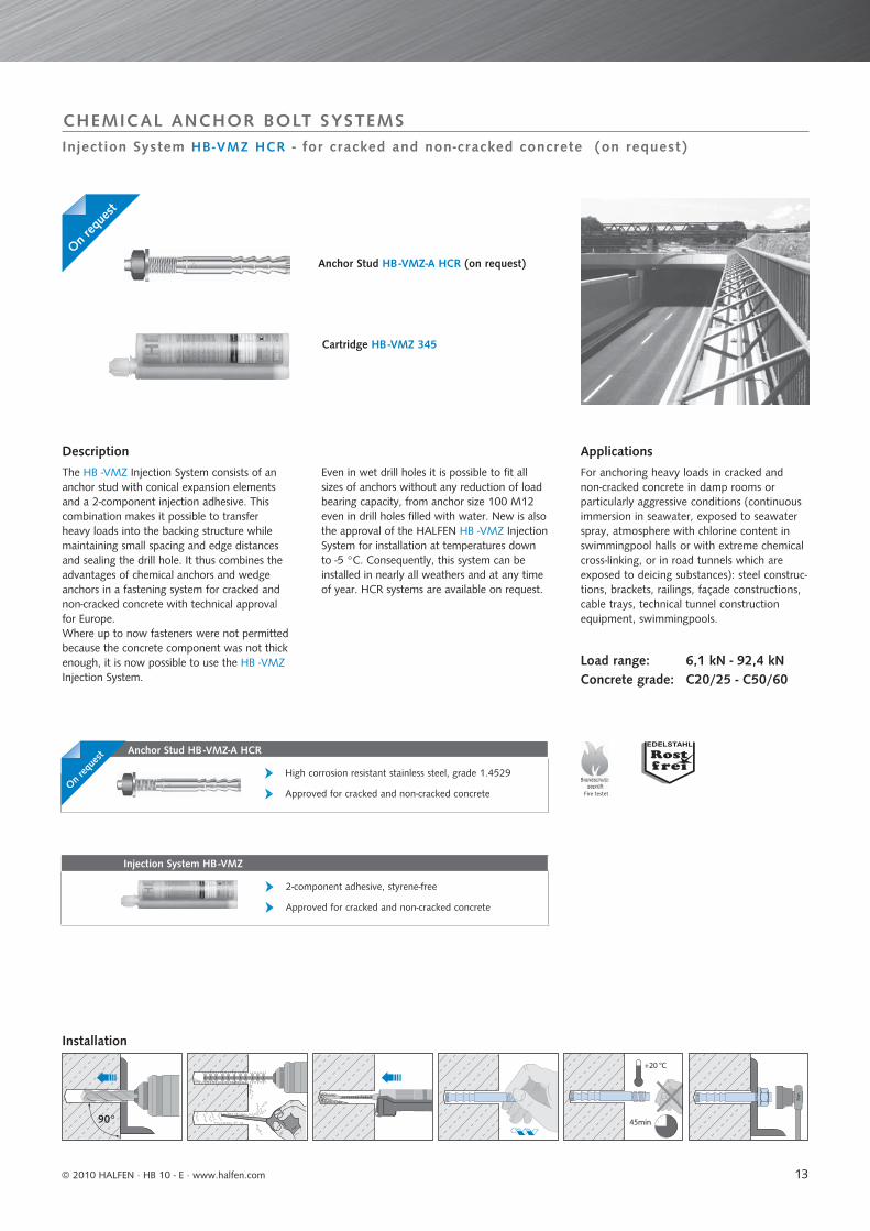
Anchor Stud HB -VMZ-A HCR
High corrosion resistant stainless steel, grade 1.4529
Approved for cracked and non-cracked concrete
Injection System HB -VMZ
2-component adhesive, styrene-free
Approved for cracked and non-cracked concrete
Fire testet
45min
+20 °C
Nm
90°
Injection System HB-VMZ HCR - for cracked and non-cracked concrete (on request)
CHEMICAL ANCHOR BOLT SYSTEMS
Cartridge HB -VMZ 345
Anchor Stud HB -VMZ-A HCR (on request)
Description
The HB -VMZ Injection System consists of ananchor stud with conical expansion elementsand a 2-component injection adhesive. Thiscombination makes it possible to transferheavy loads into the backing structure whilemaintaining small spacing and edge distancesand sealing the drill hole. It thus combines theadvantages of chemical anchors and wedgeanchors in a fastening system for cracked andnon-cracked concrete with technical approvalfor Europe.Where up to now fasteners were not permittedbecause the concrete component was not thickenough, it is now possible to use the HB -VMZInjection System.
Installation
Applications
For anchoring heavy loads in cracked andnon-cracked concrete in damp rooms orparticularly aggressive conditions (continuousimmersion in seawater, exposed to seawaterspray, atmosphere with chlorine content inswimmingpool halls or with extreme chemicalcross-linking, or in road tunnels which areexposed to deicing substances): steel construc-tions, brackets, railings, façade constructions,cable trays, technical tunnel constructionequipment, swimmingpools.
Load range: 6,1 kN - 92,4 kNConcrete grade: C20/25 - C50/60
On req
uest
On req
uest
Even in wet drill holes it is possible to fit allsizes of anchors without any reduction of load bearing capacity, from anchor size 100 M12even in drill holes filled with water. New is alsothe approval of the HALFEN HB -VMZ InjectionSystem for installation at temperatures downto -5 °C. Consequently, this system can beinstalled in nearly all weathers and at any timeof year. HCR systems are available on request.
© 2010 HALFEN · HB 10 - E · www.halfen.com
14
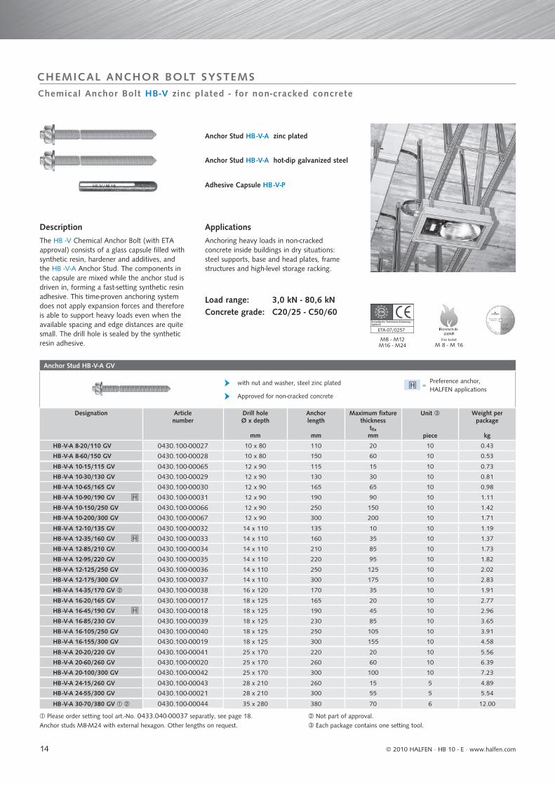
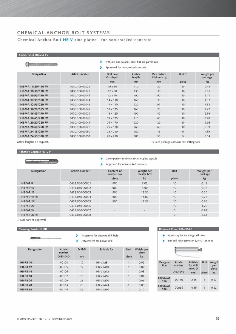
Anchor Stud HB -V-A GV
with nut and washer, steel zinc plated
Approved for non-cracked concrete
Designation Articlenumber
Drill holeØ x depth
mm
Anchorlength
mm
Maximum fixture thickness
tfixmm
Unit
piece
Weight per package
kg
HB -V-A 8-20/110 GV 0430.100-00027 10 x 80 110 20 10 0.43
HB -V-A 8-60/150 GV 0430.100-00028 10 x 80 150 60 10 0.53
HB -V-A 10-15/115 GV 0430.100-00065 12 x 90 115 15 10 0.73
HB -V-A 10-30/130 GV 0430.100-00029 12 x 90 130 30 10 0.81
HB -V-A 10-65/165 GV 0430.100-00030 12 x 90 165 65 10 0.98
HB -V-A 10-90/190 GV 0430.100-00031 12 x 90 190 90 10 1.11
HB -V-A 10-150/250 GV 0430.100-00066 12 x 90 250 150 10 1.42
HB -V-A 10-200/300 GV 0430.100-00067 12 x 90 300 200 10 1.71
HB -V-A 12-10/135 GV 0430.100-00032 14 x 110 135 10 10 1.19
HB -V-A 12-35/160 GV 0430.100-00033 14 x 110 160 35 10 1.37
HB -V-A 12-85/210 GV 0430.100-00034 14 x 110 210 85 10 1.73
HB -V-A 12-95/220 GV 0430.100-00035 14 x 110 220 95 10 1.82
HB -V-A 12-125/250 GV 0430.100-00036 14 x 110 250 125 10 2.02
HB -V-A 12-175/300 GV 0430.100-00037 14 x 110 300 175 10 2.83
HB -V-A 14-35/170 GV 0430.100-00038 16 x 120 170 35 10 1.91
HB -V-A 16-20/165 GV 0430.100-00017 18 x 125 165 20 10 2.77
HB -V-A 16-45/190 GV 0430.100-00018 18 x 125 190 45 10 2.96
HB -V-A 16-85/230 GV 0430.100-00039 18 x 125 230 85 10 3.65
HB -V-A 16-105/250 GV 0430.100-00040 18 x 125 250 105 10 3.91
HB -V-A 16-155/300 GV 0430.100-00019 18 x 125 300 155 10 4.58
HB -V-A 20-20/220 GV 0430.100-00041 25 x 170 220 20 10 5.56
HB -V-A 20-60/260 GV 0430.100-00020 25 x 170 260 60 10 6.39
HB -V-A 20-100/300 GV 0430.100-00042 25 x 170 300 100 10 7.23
HB -V-A 24-15/260 GV 0430.100-00043 28 x 210 260 15 5 4.89
HB -V-A 24-55/300 GV 0430.100-00021 28 x 210 300 55 5 5.54
HB -V-A 30-70/380 GV 0430.100-00044 35 x 280 380 70 6 12.00
Fire testet
M 8 - M 16M8 - M12M16 - M24
ETA-07/0257
Chemical Anchor Bolt HB-V zinc plated - for non-cracked concrete
CHEMICAL ANCHOR BOLT SYSTEMS
Please order setting tool art.-No. 0433.040-00037 separatly, see page 18. Not part of approval.Anchor studs M8-M24 with external hexagon. Other lengths on request. Each package contains one setting tool.
Adhesive Capsule HB -V-P
Description
The HB -V Chemical Anchor Bolt (with ETAapproval) consists of a glass capsule filled withsynthetic resin, hardener and additives, andthe HB -V-A Anchor Stud. The components inthe capsule are mixed while the anchor stud isdriven in, forming a fast-setting synthetic resinadhesive. This time-proven anchoring systemdoes not apply expansion forces and thereforeis able to support heavy loads even when theavailable spacing and edge distances are quitesmall. The drill hole is sealed by the syntheticresin adhesive.
Anchor Stud HB -V-A zinc plated
Anchor Stud HB -V-A hot-dip galvanized steel
Applications
Anchoring heavy loads in non-cracked concrete inside buildings in dry situations: steel supports, base and head plates, frame structures and high-level storage racking.
Load range: 3,0 kN - 80,6 kNConcrete grade: C20/25 - C50/60
Preference anchor, HALFEN applications=
© 2010 HALFEN · HB 10 - E ⋅ www.halfen.com
15
Adhesive Capsule HB -V-P
2-component synthetic resin in glass capsule
Approved for non-cracked concrete
Designation Article number Content of master box
piece
Weight per master box
kg
Unit
piece
Weight per package
kg
HB -V-P 8 0433.050-00001 500 7.02 10 0.13
HB -V-P 10 0433.050-00002 500 8.50 10 0.16
HB -V-P 12 0433.050-00003 500 12.30 10 0.25
HB -V-P 14 0433.050-00004 500 15.82 10 0.27
HB -V-P 16 0433.050-00005 500 19.36 10 0.36
HB -V-P 20 0433.050-00006 - - 10 1.20
HB -V-P 24 0433.050-00007 - - 5 0.87
HB -V-P 30 0433.050-00008 - - 6 2.64
Anchor Stud HB -V-A FV
with nut and washer, steel hot-dip galvanized
Approved for non-cracked concrete
Designation Article number Drill holeØ x depth
mm
Anchor length
mm
Max. fixture thickness tfix
mm
Unit
piece
Weigth per package
kg
HB -V-A 8-20/110 FV 0430.100.00022 10 x 80 110 20 10 0.43
HB -V-A 10-30/130 FV 0430.100.00023 12 x 90 130 30 10 0.81
HB -V-A 10-90/190 FV 0430.100.00045 12 x 90 190 90 10 1.11
HB -V-A 12-35/160 FV 0430.100.00024 14 x 110 160 35 10 1.37
HB -V-A 12-95/220 FV 0430.100.00046 14 x 110 220 95 10 1.82
HB -V-A 16-20/165 FV 0430.100.00047 18 x 125 165 20 10 2.77
HB -V-A 16-45/190 FV 0430.100.00025 18 x 125 190 45 10 2.96
HB -V-A 16-65/210 FV 0430.100.00048 18 x 125 210 65 10 3.20
HB -V-A 20-20/220 FV 0430.100.00049 25 x 170 220 20 10 5.56
HB -V-A 20-60/260 FV 0430.100.00026 25 x 170 260 60 10 6.39
HB -V-A 24-15/260 FV 0430.100.00050 28 x 210 260 15 5 4.89
HB -V-A 24-55/300 FV 0430.100.00051 28 x 210 300 55 5 5.54
Cleaning Brush HB -RB
Accessory for cleaning drill hole
Attachment for power drill
Designation Article number
0433.040-
Drill-Ø
mm
Suitable for Unit
piece
Weight per piecekg
HB -RB 10 -00104 10 HB -V M8 1 0,02
HB -RB 12 -00105 12 HB -V M10 1 0,02
HB -RB 14 -00106 14 HB -V M12 1 0,03
HB -RB 18 -00107 18 HB -V M16 1 0,04
HB -RB 26 -00109 26 HB -V M20 1 0,06
HB -RB 28 -00114 28 HB -V M24 1 0,08
HB -RB 35 -00115 35 HB -V M30 1 0,10
Blow-out Pump HB-VM-AP
Accessory for cleaning drill hole
For drill hole diameter 12/10 - 35 mm
Designa-tion
Article number
0433.040-
Suitable for drill holes Ø
mm
Unit
piece
Weight per
piecekg
HB-VM-AP 270 -00110 12-35 1 0,27
HB-VM-AP 360 -00069 10-35 1 0,22
CHEMICAL ANCHOR BOLT SYSTEMS
Not part of approval.
Other lengths on request. Each package contains one setting tool
Chemical Anchor Bolt HB-V zinc plated - for non-cracked concrete
© 2010 HALFEN · HB 10 - E · www.halfen.com
16
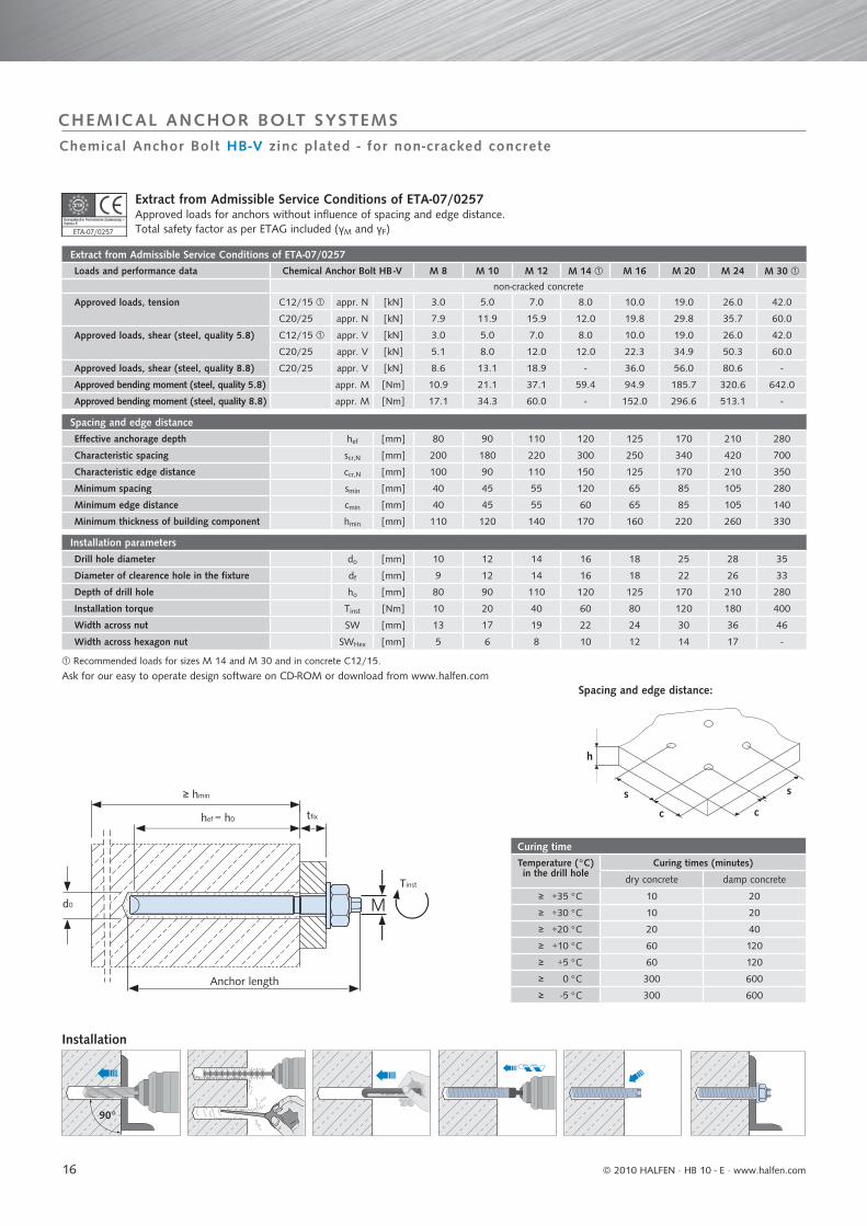
Extract from Admissible Service Conditions of ETA-07/0257 Loads and performance data Chemical Anchor Bolt HB -V M 8 M 10 M 12 M 14 M 16 M 20 M 24 M 30
non-cracked concrete
Approved loads, tension C12/15 appr. N [kN] 3.0 5.0 7.0 8.0 10.0 19.0 26.0 42.0
C20/25 appr. N [kN] 7.9 11.9 15.9 12.0 19.8 29.8 35.7 60.0
Approved loads, shear (steel, quality 5.8) C12/15 appr. V [kN] 3.0 5.0 7.0 8.0 10.0 19.0 26.0 42.0
C20/25 appr. V [kN] 5.1 8.0 12.0 12.0 22.3 34.9 50.3 60.0
Approved loads, shear (steel, quality 8.8) C20/25 appr. V [kN] 8.6 13.1 18.9 - 36.0 56.0 80.6 -
Approved bending moment (steel, quality 5.8) appr. M [Nm] 10.9 21.1 37.1 59.4 94.9 185.7 320.6 642.0
Approved bending moment (steel, quality 8.8) appr. M [Nm] 17.1 34.3 60.0 - 152.0 296.6 513.1 -
Spacing and edge distance
Effective anchorage depth hef [mm] 80 90 110 120 125 170 210 280
Characteristic spacing scr,N [mm] 200 180 220 300 250 340 420 700
Characteristic edge distance ccr,N [mm] 100 90 110 150 125 170 210 350
Minimum spacing smin [mm] 40 45 55 120 65 85 105 280
Minimum edge distance cmin [mm] 40 45 55 60 65 85 105 140
Minimum thickness of building component hmin [mm] 110 120 140 170 160 220 260 330
Installation parameters
Drill hole diameter do [mm] 10 12 14 16 18 25 28 35
Diameter of clearence hole in the fixture df [mm] 9 12 14 16 18 22 26 33
Depth of drill hole ho [mm] 80 90 110 120 125 170 210 280
Installation torque Tinst [Nm] 10 20 40 60 80 120 180 400
Width across nut SW [mm] 13 17 19 22 24 30 36 46
Width across hexagon nut SWHex [mm] 5 6 8 10 12 14 17 -
Curing timeTemperature (°C) in the drill hole
Curing times (minutes)
dry concrete damp concrete
≥ +35 °C 10 20
≥ +30 °C 10 20
≥ +20 °C 20 40
≥ +10 °C 60 120
≥ +5 °C 60 120
≥ 0 °C 300 600
≥ -5 °C 300 600
VERBUND ANKER VA
90°
s
cc
h
s
M
≥ hmin
hef = h0 tfi x
Tinst
d0
ETA-07/0257
CHEMICAL ANCHOR BOLT SYSTEMS
Extract from Admissible Service Conditions of ETA-07/0257 Approved loads for anchors without influence of spacing and edge distance.Total safety factor as per ETAG included (γM and γF)
Recommended loads for sizes M 14 and M 30 and in concrete C12/15.
Chemical Anchor Bolt HB-V zinc plated - for non-cracked concrete
Installation
Ask for our easy to operate design software on CD-ROM or download from www.halfen.com
Anchor length
Spacing and edge distance:
© 2010 HALFEN · HB 10 - E ⋅ www.halfen.com

17
Anchor Stud HB -V-A A4
with nut and washer, stainless steel A4
Approved for non-cracked concrete
Designation Article number Drill holeØ x depth
mm
Anchor lengthmm
Maximum fixture thicknesstfix mm
Unit
piece
Weight per package
kg
HB -V-A 8-20/110 A4 0430.100-00001 10 x 80 110 20 10 0.43
HB -V-A 8-60/150 A4 0430.100-00052 10 x 80 150 60 10 0.53
HB -V-A 10-15/115 A4 0430.100-00002 12 x 90 115 15 10 0.73
HB -V-A 10-30/130 A4 0430.100-00003 12 x 90 130 30 10 0.81
HB -V-A 10-65/165 A4 0430.100-00004 12 x 90 165 65 10 0.98
HB -V-A 10-90/190 A4 0430.100-00053 12 x 90 190 90 10 1.11
HB -V-A 10-150/250 A4 0430.100-00068 12 x 90 250 150 10 1.42
HB -V-A 10-200/300 A4 0430.100-00069 12 x 90 300 200 10 1.71
HB -V-A 12-10/135 A4 0430.100-00005 14 x 110 135 10 10 1.19
HB -V-A 12-35/160 A4 0430.100-00006 14 x 110 160 35 10 1.37
HB -V-A 12-55/180 A4 0430.100-00007 14 x 110 180 55 10 1.51
HB -V-A 12-65/190 A4 0430.100-00064 14 x 110 190 65 10 1.58
HB -V-A 12-85/210 A4 0430.100-00054 14 x 110 210 85 10 1.73
HB -V-A 12-95/220 A4 0430.100-00055 14 x 110 220 95 10 1.82
HB -V-A 12-125/250 A4 0430.100-00056 14 x 110 250 125 10 2.02
HB -V-A 12-175/300 A4 0430.100-00008 14 x 110 300 175 10 2.83
HB -V-A 14-35/170 A4 0430.100-00057 16 x 120 170 35 10 1.91
HB -V-A 16-5/150 A4 0430.100-00009 18 x 125 150 5 10 2.38
HB -V-A 16-20/165 A4 0430.100-00010 18 x 125 165 20 10 2.77
HB -V-A 16-45/190 A4 0430.100-00011 18 x 125 190 45 10 2.96
HB -V-A 16-65/210 A4 0430.100-00012 18 x 125 210 65 10 3.20
HB -V-A 16-85/230 A4 0430.100-00058 18 x 125 130 85 10 3.65
HB -V-A 16-105/250 A4 0430.100-00013 18 x 125 250 105 10 3.91
HB -V-A 16-155/300 A4 0430.100-00059 18 x 125 300 155 10 4.58
HB -V-A 20-20/220 A4 0430.100-00014 25 x 170 220 20 10 5.56
HB -V-A 20-60/260 A4 0430.100-00015 25 x 170 260 60 10 6.39
HB -V-A 20-100/300 A4 0430.100-00060 25 x 170 300 100 10 7.23
HB -V-A 24-15/260 A4 0430.100-00061 28 x 210 260 15 5 4.89
HB -V-A 24-55/300 A4 0430.100-00016 28 x 210 300 55 5 5.54
HB -V-A 30-70/380 A4 0430.100-00062 35 x 280 380 70 6 12.00
M 8 - M 16M8 - M12M16 - M24
Chemical Anchor Bolt HB-V A4 - for non-cracked concrete
CHEMICAL ANCHOR BOLT SYSTEMS
Anchor Studs M 8 - M 24 with external hexagon head. Other lengths on request. Please order setting tool art.-No. 0433.040-00037 separately. See → p. 18 Not part of approval. Each package contains one setting tool.
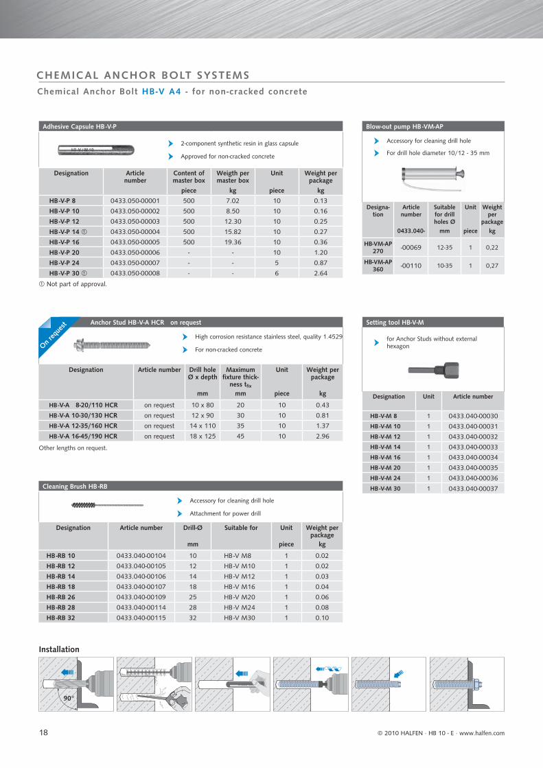
Adhesive Capsule HB -V-P
Description
The HB -V A4 Chemical Anchor Bolt (with ETAapproval) consists of a glass capsule filled withsynthetic resin, hardener and quartz additives,as well as the HB -V-A Anchor Stud. The components in the capsule are mixed while the anchor stud is driven in, forming a fast setting synthetic resin adhesive. This time proven an-choring system does not apply expansion forces and therefore is able to support heavy loads even when the available spacing and edge distances are quite small. The drill hole is sealed by the synthetic resin adhesive.
Anchor Stud HB -V-A A4
Applications
Anchoring heavy loads in non-crackedconcrete inside buildings, outside buildingsand in damp rooms without aggressiveconditions: supports, base and head plates,brackets, façades, crash barriers, railings,noise protection walls.
Load range: 3,0 kN - 60,0 kNConcrete grade: C12/15 - C50/60
suitable for fixing HALFEN Support Brackets.=
ETA-07/0257
Preference anchor, HALFEN applications=
© 2010 HALFEN · HB 10 - E · www.halfen.com
18
Anchor Stud HB -V-A HCR on request
High corrosion resistance stainless steel, quality 1.4529
For non-cracked concrete
Designation Article number Drill holeØ x depth
mm
Maximum fixture thick-
ness tfixmm
Unit
piece
Weight per package
kg
HB -V-A 8-20/110 HCR on request 10 x 80 20 10 0.43
HB -V-A 10-30/130 HCR on request 12 x 90 30 10 0.81
HB -V-A 12-35/160 HCR on request 14 x 110 35 10 1.37
HB -V-A 16-45/190 HCR on request 18 x 125 45 10 2.96
Setting tool HB-V-M
for Anchor Studs without external hexagon
Designation Unit Article number
HB -V-M 8 1 0433.040-00030
HB -V-M 10 1 0433.040-00031
HB -V-M 12 1 0433.040-00032
HB -V-M 14 1 0433.040-00033
HB -V-M 16 1 0433.040-00034
HB -V-M 20 1 0433.040-00035
HB -V-M 24 1 0433.040-00036
HB -V-M 30 1 0433.040-00037Cleaning Brush HB -RB
Accessory for cleaning drill hole
Attachment for power drill
Designation Article number Drill-Ø
mm
Suitable for Unit
piece
Weight per package
kg
HB -RB 10 0433.040-00104 10 HB -V M8 1 0.02
HB -RB 12 0433.040-00105 12 HB -V M10 1 0.02
HB -RB 14 0433.040-00106 14 HB -V M12 1 0.03
HB -RB 18 0433.040-00107 18 HB -V M16 1 0.04
HB -RB 26 0433.040-00109 25 HB -V M20 1 0.06
HB -RB 28 0433.040-00114 28 HB -V M24 1 0.08
HB -RB 32 0433.040-00115 32 HB -V M30 1 0.10
Adhesive Capsule HB -V-P
2-component synthetic resin in glass capsule
Approved for non-cracked concrete
Designation Article number
Content of master box
piece
Weigth per master box
kg
Unit
piece
Weight per package
kg
HB -V-P 8 0433.050-00001 500 7.02 10 0.13
HB -V-P 10 0433.050-00002 500 8.50 10 0.16
HB -V-P 12 0433.050-00003 500 12.30 10 0.25
HB -V-P 14 0433.050-00004 500 15.82 10 0.27
HB -V-P 16 0433.050-00005 500 19.36 10 0.36
HB -V-P 20 0433.050-00006 - - 10 1.20
HB -V-P 24 0433.050-00007 - - 5 0.87
HB -V-P 30 0433.050-00008 - - 6 2.64
Blow-out pump HB -VM-AP
Accessory for cleaning drill hole
For drill hole diameter 10/12 - 35 mm
Designa-tion
Article number
0433.040-
Suitable for drill holes Ø
mm
Unit
piece
Weight per
packagekg
HB-VM-AP 270 -00069 12-35 1 0,22
HB-VM-AP 360 -00110 10-35 1 0,27
VERBUND ANKER VA
90°
Chemical Anchor Bolt HB-V A4 - for non-cracked concrete
CHEMICAL ANCHOR BOLT SYSTEMS
Installation
Other lengths on request.
Not part of approval.
On req
uest
© 2010 HALFEN · HB 10 - E ⋅ www.halfen.com
19
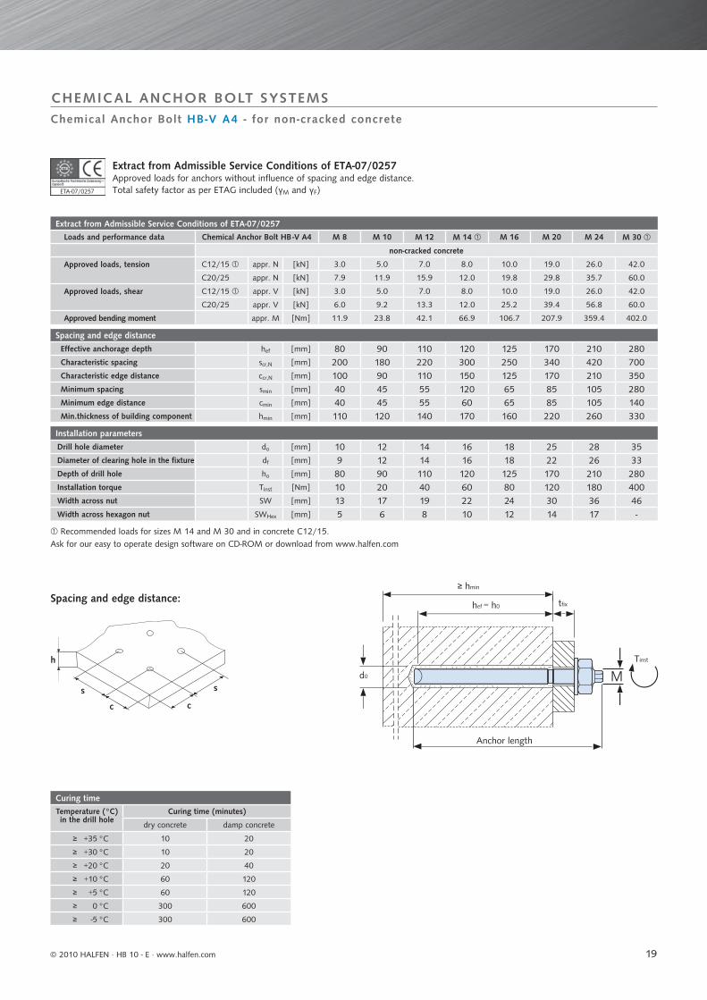
Extract from Admissible Service Conditions of ETA-07/0257 Loads and performance data Chemical Anchor Bolt HB -V A4 M 8 M 10 M 12 M 14 M 16 M 20 M 24 M 30
non-cracked concrete
Approved loads, tension C12/15 appr. N [kN] 3.0 5.0 7.0 8.0 10.0 19.0 26.0 42.0
C20/25 appr. N [kN] 7.9 11.9 15.9 12.0 19.8 29.8 35.7 60.0
Approved loads, shear C12/15 appr. V [kN] 3.0 5.0 7.0 8.0 10.0 19.0 26.0 42.0
C20/25 appr. V [kN] 6.0 9.2 13.3 12.0 25.2 39.4 56.8 60.0
Approved bending moment appr. M [Nm] 11.9 23.8 42.1 66.9 106.7 207.9 359.4 402.0
Spacing and edge distance
Effective anchorage depth hef [mm] 80 90 110 120 125 170 210 280Characteristic spacing scr,N [mm] 200 180 220 300 250 340 420 700Characteristic edge distance ccr,N [mm] 100 90 110 150 125 170 210 350Minimum spacing smin [mm] 40 45 55 120 65 85 105 280Minimum edge distance cmin [mm] 40 45 55 60 65 85 105 140Min.thickness of building component hmin [mm] 110 120 140 170 160 220 260 330
Installation parameters
Drill hole diameter do [mm] 10 12 14 16 18 25 28 35Diameter of clearing hole in the fixture df [mm] 9 12 14 16 18 22 26 33Depth of drill hole ho [mm] 80 90 110 120 125 170 210 280Installation torque Tinst [Nm] 10 20 40 60 80 120 180 400Width across nut SW [mm] 13 17 19 22 24 30 36 46Width across hexagon nut SWHex [mm] 5 6 8 10 12 14 17 -
Curing timeTemperature (°C) in the drill hole
Curing time (minutes)
dry concrete damp concrete
≥ +35 °C 10 20
≥ +30 °C 10 20
≥ +20 °C 20 40
≥ +10 °C 60 120
≥ +5 °C 60 120
≥ 0 °C 300 600
≥ -5 °C 300 600
s
cc
h
sM
≥ hmin
hef = h0 tfi x
Tinst
d0
CHEMICAL ANCHOR BOLT SYSTEMS
Extract from Admissible Service Conditions of ETA-07/0257 Approved loads for anchors without influence of spacing and edge distance.Total safety factor as per ETAG included (γM and γF)
Recommended loads for sizes M 14 and M 30 and in concrete C12/15.
Chemical Anchor Bolt HB-V A4 - for non-cracked concrete
Ask for our easy to operate design software on CD-ROM or download from www.halfen.com
ETA-07/0257
Anchor length
Spacing and edge distance:
© 2010 HALFEN · HB 10 - E · www.halfen.com
20
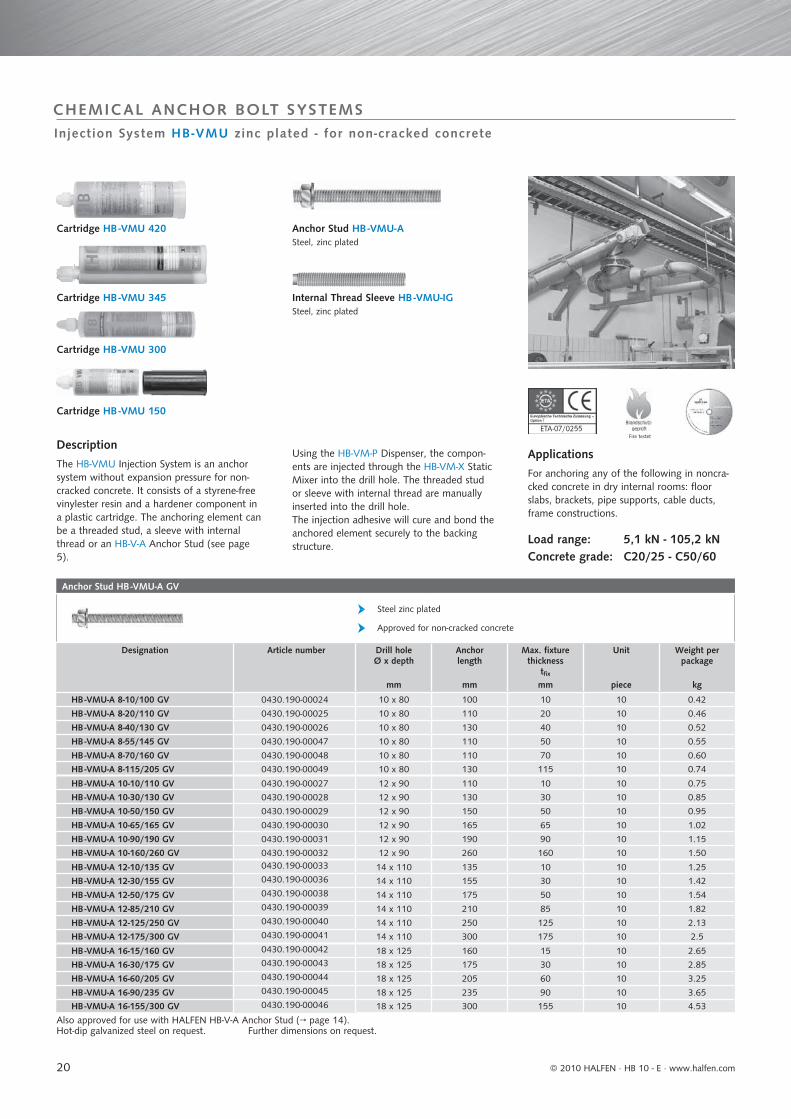
Anchor Stud HB -VMU-A GV
Steel zinc plated
Approved for non-cracked concrete
Designation Article number Drill holeØ x depth
mm
Anchor length
mm
Max. fixture thickness
tfixmm
Unit
piece
Weight per package
kg
HB -VMU-A 8-10/100 GV 0430.190-00024 10 x 80 100 10 10 0.42
HB -VMU-A 8-20/110 GV 0430.190-00025 10 x 80 110 20 10 0.46
HB -VMU-A 8-40/130 GV 0430.190-00026 10 x 80 130 40 10 0.52
HB -VMU-A 8-55/145 GV 0430.190-00047 10 x 80 110 50 10 0.55
HB -VMU-A 8-70/160 GV 0430.190-00048 10 x 80 110 70 10 0.60
HB -VMU-A 8-115/205 GV 0430.190-00049 10 x 80 130 115 10 0.74
HB -VMU-A 10-10/110 GV 0430.190-00027 12 x 90 110 10 10 0.75
HB -VMU-A 10-30/130 GV 0430.190-00028 12 x 90 130 30 10 0.85
HB -VMU-A 10-50/150 GV 0430.190-00029 12 x 90 150 50 10 0.95
HB -VMU-A 10-65/165 GV 0430.190-00030 12 x 90 165 65 10 1.02
HB -VMU-A 10-90/190 GV 0430.190-00031 12 x 90 190 90 10 1.15
HB -VMU-A 10-160/260 GV 0430.190-00032 12 x 90 260 160 10 1.50
HB -VMU-A 12-10/135 GV 0430.190-00033 14 x 110 135 10 10 1.25
HB -VMU-A 12-30/155 GV 0430.190-00036 14 x 110 155 30 10 1.42
HB -VMU-A 12-50/175 GV 0430.190-00038 14 x 110 175 50 10 1.54
HB -VMU-A 12-85/210 GV 0430.190-00039 14 x 110 210 85 10 1.82
HB -VMU-A 12-125/250 GV 0430.190-00040 14 x 110 250 125 10 2.13
HB -VMU-A 12-175/300 GV 0430.190-00041 14 x 110 300 175 10 2.5
HB -VMU-A 16-15/160 GV 0430.190-00042 18 x 125 160 15 10 2.65
HB -VMU-A 16-30/175 GV 0430.190-00043 18 x 125 175 30 10 2.85
HB -VMU-A 16-60/205 GV 0430.190-00044 18 x 125 205 60 10 3.25
HB -VMU-A 16-90/235 GV 0430.190-00045 18 x 125 235 90 10 3.65
HB -VMU-A 16-155/300 GV 0430.190-00046 18 x 125 300 155 10 4.53
Fire testetETA-07/02557
Injection System HB-VMU zinc plated - for non-cracked concrete
CHEMICAL ANCHOR BOLT SYSTEMS
Description
The HB-VMU Injection System is an anchorsystem without expansion pressure for non-cracked concrete. It consists of a styrene-free vinylester resin and a hardener component in a plastic cartridge. The anchoring element can be a threaded stud, a sleeve with internalthread or an HB-V-A Anchor Stud (see page 5).
Cartridge HB -VMU 345
Cartridge HB -VMU 300
Cartridge HB -VMU 420
Internal Thread Sleeve HB -VMU-IG Steel, zinc plated
Cartridge HB -VMU 150
Anchor Stud HB -VMU-A Steel, zinc plated
Using the HB-VM-P Dispenser, the compon-ents are injected through the HB-VM-X Static Mixer into the drill hole. The threaded stud or sleeve with internal thread are manually inserted into the drill hole. The injection adhesive will cure and bond theanchored element securely to the backingstructure.
Also approved for use with HALFEN HB-V-A Anchor Stud (→ page 14).Hot-dip galvanized steel on request. Further dimensions on request.
Applications
For anchoring any of the following in noncra-cked concrete in dry internal rooms: floorslabs, brackets, pipe supports, cable ducts,frame constructions.
Load range: 5,1 kN - 105,2 kNConcrete grade: C20/25 - C50/60
© 2010 HALFEN · HB 10 - E ⋅ www.halfen.com
21
Internally Threaded Sleeve HB -VMU-IG
Steel, zinc plated
For non-cracked concrete
Designation Article number Drill holeØ x depth
mm
Outer-Ø x Anchor length
mm
Screwing depthmin s / max s
mm
Unit
piece
Weight per package
kg
HB -VMU-IG M6 GV 0430.230-00003 12 x 98 10 x 93 8 / 20 10 0.65
HB -VMU-IG M8 GV 0430.230-00004 14 x 98 12 x 93 8 / 20 10 0.95
Dispenser HB -VM-P
Designation Article number
0433.040-
Weight per piece kg
Dispenser HB-VM-P 345 -00077 0.87
DispenserHB-VM-P 345 Profi -00078 1.20
Dispenser HB-VM-P 420 -00079 1.80
Dispenser HB-VM-P 420 Profi -00080 1.22
also appropriate to 345ml cartridge
Blow-out pump HB -VM-AP
Accessory for cleaning drill hole
For drill hole diameter 10 - 35 mm
Designation Article number
0433.040-
for drill holes
Ømm
Unit
piece
Weight per
packagekg
HB-VM-AP 360 -00110 10 - 35 1 0.27
Injection System HB -VMU / Mixing Nozzle
Designation Article number
0433.040-
Content
ml
Content of master box
piece
Weight per master box
kg
Weight per piecekg
Cartridge HB-VMU 150 -00129 150 12 4.20 0.34
Cartridge HB-VMU 300 -00130 300 12 6.40 0.53
Cartridge HB-VMU 345 -00131 345 12 8.00 0.65
Cartridge HB-VMU 420 -00134 420 12 10.1 0.83
Mixing Nozzle HB-VM-X -00039 - 12 0.12 0.01
Mixing Nozzle HB-VMU-X -00135 - 10 0.10 0.01
Mixer Extension HB-VM-XE (200mm) -00076 - - - 0.01
HB-VMU 150 and HB -VMU 300 can also be dispensed with a standard silicone dispenser. Single cartridges can also be supplied. Only cartridge HB-VMU 420
One mixing nozzle is included with each cartridge.
Cleaning Brush HB -RB
Accessory for cleaning drill hole
For non-cracked concrete
Designation Article number0433.040-
Drill-Ø
mm
Suitable for Unit
piece
Weight per piecekg
HB -RB 10 -00104 10 HB -VMU M8 1 0.02
HB -RB 12 -00105 12 HB -VMU M10 1 0.02
HB -RB 14 -00106 14 HB -VMU M12 1 0.03
HB -RB 18 -00107 18 HB -VMU M16 1 0.04
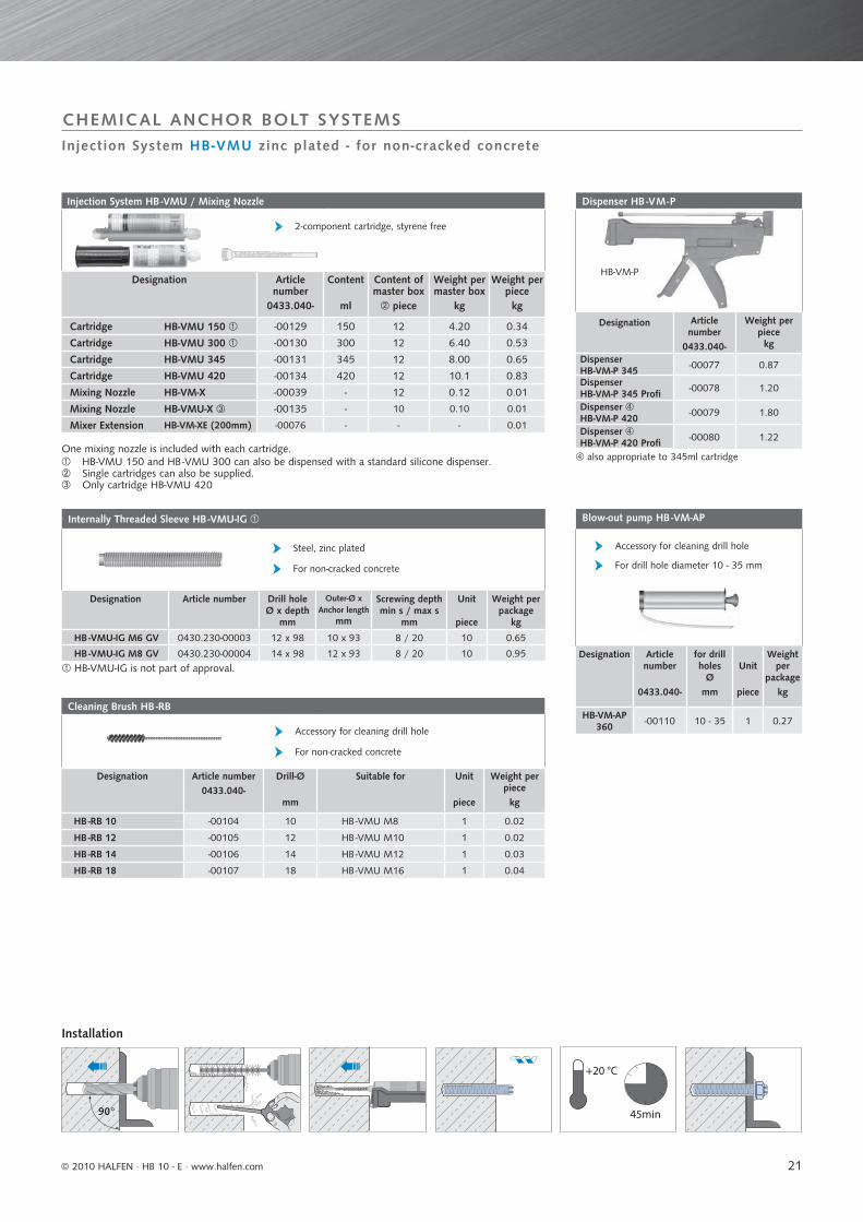
2-component cartridge, styrene free
90° 45min
+20 °C
Injection System HB-VMU zinc plated - for non-cracked concrete
CHEMICAL ANCHOR BOLT SYSTEMS
Installation
HB-VMU-IG is not part of approval.
HB-VM-P
© 2010 HALFEN · HB 10 - E · www.halfen.com

22
Extract from Admissible Service Conditions of ETA-07/0255.Loads and performance data Injection System HB -VMU M8 M 10 M 12 M 16 M20 M24 M30
non-cracked concrete
Approved loads, tension (steel 5.8) C20/25 appr. N [kN] 7.6 11.9 16.7 23.8 45.2 54.8 81.0
C25/30 appr. N [kN] 8.1 12.6 17.7 25.2 48.0 58.0 85.8
C30/37 appr. N [kN] 8.5 13.3 18.7 26.7 50.7 61.3 90.7
C40/50 appr. N [kN] 8.6 13.8 20.0 29.3 55.6 67.4 99.6
C50/60 appr. N [kN] 8.6 13.8 20.0 31.0 58.6 71.2 105.2
Approved loads, shear (steel 5.8) C20/25 appr. V [kN] 5.1 8.6 12.0 22.3 34.9 50.3 80.0
Approved bending moment (steel 5.8) appr. M [Nm] 10.9 21.1 37.1 94.3 185.7 320.6 642.3
Spacing and edge distanceEffective anchorage depth hef [mm] 80 90 110 125 170 210 270
Characteristic spacing scr,N [mm] 160 180 220 250 340 420 540
Characteristic edge distance ccr,N [mm] 80 90 110 125 170 210 270
Minimum spacing hmin [mm] 100 130 160 200 220 280 350
Minimum edge distance hmin,red [mm] - 120 140 160 - - -
Minimum thickness of building component smin [mm] 40 45 55 65 85 105 135
Minimum thickness of building cmin [mm] 40 45 55 65 85 105 135
Installation parametersDrill hole diameter do [mm] 10 12 14 18 22 26 32
Diameter of clearing hole in the fixture df [mm] 9 12 14 18 22 26 33
Depth of drill hole ho [mm] 80 90 110 125 170 210 270
Installation torque Tinst [Nm] 10 20 40 60 120 150 300
Width across nut SW [mm] 13 17 19 24 30 36 46
Drill hole fill quantity, scaling on 300/345 Cartridge [mm] 4/3 5/4 7/6 11/10 21/17 35/27 57/49
Adhesive required per drill hole [ml] 5.2 7.3 10.8 17.1 30.4 51.0 82.0
Drill holes per VMU 300 / VMU 345 Cartridge [piece] 50/58 35/41 24/28 15/17 8/10 5/6 3/3.5
Processing and curing timesTemperature (°C)in the drill hole
Processing time Curing time
dry concrete damp concrete
Minutes Minutes Minutes≥ +40 °C 1.4 15 30≥ +35 °C 2 20 40≥ +30 °C 4 25 50≥ +20 °C 6 45 90≥ +10 °C 12 80 160≥ +5 °C 20 120 240≥ 0 °C 45 180 360≥ -5 °C 90 330 660
M
≥ hmin
hef = h0 tfi x
Tinst
d0
s
cc
h
s
ETA-07/02557
Injection System HB-VMU zinc plated - for non-cracked concrete
CHEMICAL ANCHOR BOLT SYSTEMS
Extract from Admissible Service Conditions of ETA-07/0255.Approved loads for anchors without influence of spacing and edge distance. Total safety factor as per ETAG included (γM and γF)
For technical data for solid and perforated brickwork see page 28.
Spacing and edge distance:
Anchor lenght
© 2010 HALFEN · HB 10 - E ⋅ www.halfen.com
23
Anchor Stud HB -VMU-A A4
Stainless steel A4
Approved for non-cracked concrete
Designation Articlenumber
Drill holeØ x depth
mm
Anchor length
mm
Max. fixturethickness
tfixmm
Unit
piece
Weight per package
kg
HB -VMU-A 8-10/100 A4 0430.190-00001 10 x 80 100 10 10 0.42
HB -VMU-A 8-20/110 A4 0430.190-00002 10 x 80 110 20 10 0.46
HB -VMU-A 8-40/130 A4 0430.190-00003 10 x 80 130 40 10 0.52
HB -VMU-A 8-55/145 A4 0430.190-00050 10 x 80 145 55 10 0.55
HB -VMU-A 8-70/160 A4 0430.190-00051 10 x 80 160 70 10 0.60
HB -VMU-A 8-115/205 A4 0430.190-00052 10 x 80 205 115 10 0.74
HB -VMU-A 10-10/110 A4 0430.190-00004 12 x 90 110 10 10 0.75
HB -VMU-A 10-30/130 A4 0430.190-00005 12 x 90 130 30 10 0.85
HB -VMU-A 10-50/150 A4 0430.190-00006 12 x 90 150 50 10 0.95
HB -VMU-A 10-65/165 A4 0430.190-00007 12 x 90 165 65 10 1.02
HB -VMU-A 10-90/190 A4 0430.190-00008 12 x 90 190 90 10 1.15
HB -VMU-A 10-160/260 A4 0430.190-00009 12 x 90 260 160 10 1.50
HB -VMU-A 12-10/135 A4 0430.190-00010 14 x 110 135 10 10 1.25
HB -VMU-A 12-30/155 A4 0430.190-00013 14 x 110 155 30 10 1.42
HB -VMU-A 12-50/175 A4 0430.190-00015 14 x 110 175 50 10 1.54
HB -VMU-A 12-85/210 A4 0430.190-00016 14 x 110 210 85 10 1.82
HB -VMU-A 12-125/250 A4 0430.190-00017 14 x 110 250 125 10 2.13
HB -VMU-A 12-175/300 A4 0430.190-00018 14 x 110 300 175 10 2.50
HB -VMU-A 16-15/160 A4 0430.190-00019 18 x 125 160 15 10 2.65
HB -VMU-A 16-30/175 A4 0430.190-00020 18 x 125 175 30 10 2.85
HB -VMU-A 16-60/205 A4 0430.190-00021 18 x 125 205 60 10 3.25
HB -VMU-A 16-90/235 A4 0430.190-00022 18 x 125 235 90 10 3.65
HB -VMU-A 16-155/300 A4 0430.190-00023 18 x 125 300 155 10 4.53
Also approved for use with HALFEN HB-V-A A4 Anchor Stud (→ page 17). HCR stainless steel on request.
Fire testet
ETA-07/02557
Injection System HB-VMU A4 - for non-cracked concrete
CHEMICAL ANCHOR BOLT SYSTEMS
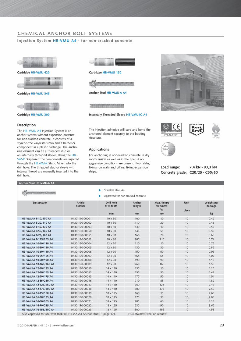
Description
The HB -VMU A4 Injection System is ananchor system without expansion pressurefor non-cracked concrete. It consists of astyrene-free vinylester resin and a hardenercomponent in a plastic cartridge. The ancho-ring element can be a threaded stud oran internally threaded sleeve. Using the HB -VM-P Dispenser, the components are injectedthrough the HB -VM-X Static Mixer into thedrill hole. The threaded stud or sleeve withinternal thread are manually inserted into thedrill hole.
Cartridge HB -VMU 345
Cartridge HB -VMU 300
Cartridge HB -VMU 420
Internally Threaded Sleeve HB -VMU-IG A4
Cartridge HB -VMU 150
Anchor Stud HB -VMU-A A4
The injection adhesive will cure and bond theanchored element securely to the backingstructure.
Applications
For anchoring in non-cracked concrete in dryrooms inside as well as in the open if no aggressive conditions are present: floor slabs, fixings on walls and pillars, fixing expansion strips.
Load range: 7,4 kN - 83,3 kNConcrete grade: C20/25 - C50/60
© 2010 HALFEN · HB 10 - E · www.halfen.com
24
Internally Threaded Sleeve HB -VMU-IG A4
Stainless steel A4
Approved for non-cracked concrete
Designation Article0430.230-
Drill holeØ x depth
mm
Outer-Ø x Anchor lengthmm
Screwing depthmin s / max s
mm
Unit
piece
Weight per package
kg
HB -VMU-IG M6 A4 -00001 12 x 98 10 x 93 8 / 20 10 0,65
HB -VMU-IG M8 A4 -00002 14 x 98 12 x 93 8 / 20 10 0,95
Blow-out pump HB -VM-AP
Accessory for cleaning drill hole
For drill hole diameter 10 - 35 mm
Designa-tion
Article number
0433.040-
Suitable for drill holes Ø
mm
Unit
piece
Weight per
piecekg
HB-VM-AP 360 -00110 10 - 35 1 0,27
Dispenser HB -VM-P
Designation Article number
0433.040-
Weight per piece kg
Dispenser HB-VM-P 345 -00077 0,87
Dispenser HB-VM-P 345 Profi -00078 1,20
Dispenser HB-VM-P 420 -00079 1.80
Dispenser HB-VM-P 420 Profi -00080 1.22
also appropriate to 345ml cartridge
Injection System HB -VMU / Mixing Nozzle
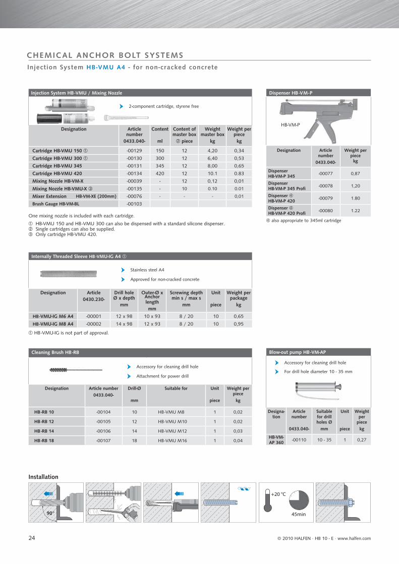
2-component cartridge, styrene free
Designation Article number
0433.040-
Content
ml
Content of master box
piece
Weight master box
kg
Weight per piecekg
Cartridge HB-VMU 150 -00129 150 12 4,20 0,34
Cartridge HB-VMU 300 -00130 300 12 6,40 0,53
Cartridge HB-VMU 345 -00131 345 12 8,00 0,65
Cartridge HB-VMU 420 -00134 420 12 10.1 0.83
Mixing Nozzle HB-VM-X -00039 - 12 0,12 0,01
Mixing Nozzle HB-VMU-X -00135 - 10 0.10 0.01
Mixer Extension HB-VM-XE (200mm) -00076 - - - 0,01
Brush Gauge HB-VM-BL -00103
Cleaning Brush HB -RB
Accessory for cleaning drill hole
Attachment for power drill
Designation Article number0433.040-
Drill-Ø
mm
Suitable for Unit
piece
Weight per piecekg
HB -RB 10 -00104 10 HB -VMU M8 1 0,02
HB -RB 12 -00105 12 HB -VMU M10 1 0,02
HB -RB 14 -00106 14 HB -VMU M12 1 0,03
HB -RB 18 -00107 18 HB -VMU M16 1 0,04
45min
+20 °C
90°
HB-VM-P
Injection System HB-VMU A4 - for non-cracked concrete
CHEMICAL ANCHOR BOLT SYSTEMS
HB -VMU-IG is not part of approval.
HB-VMU 150 and HB -VMU 300 can also be dispensed with a standard silicone dispenser. Single cartridges can also be supplied. Only cartridge HB-VMU 420.
One mixing nozzle is included with each cartridge.
Installation
© 2010 HALFEN · HB 10 - E ⋅ www.halfen.com
25
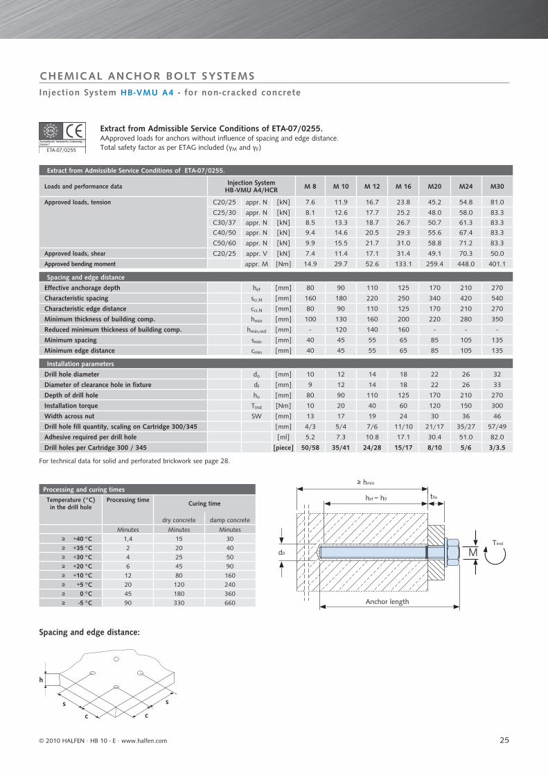
Extract from Admissible Service Conditions of ETA-07/0255.
Loads and performance data Injection System HB -VMU A4/HCR M 8 M 10 M 12 M 16 M20 M24 M30
Approved loads, tension C20/25 appr. N [kN] 7.6 11.9 16.7 23.8 45.2 54.8 81.0
C25/30 appr. N [kN] 8.1 12.6 17.7 25.2 48.0 58.0 83.3
C30/37 appr. N [kN] 8.5 13.3 18.7 26.7 50.7 61.3 83.3
C40/50 appr. N [kN] 9.4 14.6 20.5 29.3 55.6 67.4 83.3
C50/60 appr. N [kN] 9.9 15.5 21.7 31.0 58.8 71.2 83.3
Approved loads, shear C20/25 appr. V [kN] 7.4 11.4 17.1 31.4 49.1 70.3 50.0
Approved bending moment appr. M [Nm] 14.9 29.7 52.6 133.1 259.4 448.0 401.1
Spacing and edge distance
Effective anchorage depth hef [mm] 80 90 110 125 170 210 270
Characteristic spacing scr,N [mm] 160 180 220 250 340 420 540
Characteristic edge distance ccr,N [mm] 80 90 110 125 170 210 270
Minimum thickness of building comp. hmin [mm] 100 130 160 200 220 280 350
Reduced minimum thickness of building comp. hmin,red [mm] - 120 140 160 - - -
Minimum spacing smin [mm] 40 45 55 65 85 105 135
Minimum edge distance cmin [mm] 40 45 55 65 85 105 135
Installation parameters
Drill hole diameter do [mm] 10 12 14 18 22 26 32
Diameter of clearance hole in fixture df [mm] 9 12 14 18 22 26 33
Depth of drill hole ho [mm] 80 90 110 125 170 210 270
Installation torque Tinst [Nm] 10 20 40 60 120 150 300
Width across nut SW [mm] 13 17 19 24 30 36 46
Drill hole fill quantity, scaling on Cartridge 300/345 [mm] 4/3 5/4 7/6 11/10 21/17 35/27 57/49
Adhesive required per drill hole [ml] 5.2 7.3 10.8 17.1 30.4 51.0 82.0
Drill holes per Cartridge 300 / 345 [piece] 50/58 35/41 24/28 15/17 8/10 5/6 3/3.5
Processing and curing timesTemperature (°C)in the drill hole
Processing time Curing time
dry concrete damp concrete
Minutes Minutes Minutes≥ +40 °C 1,4 15 30≥ +35 °C 2 20 40≥ +30 °C 4 25 50≥ +20 °C 6 45 90≥ +10 °C 12 80 160≥ +5 °C 20 120 240≥ 0 °C 45 180 360≥ -5 °C 90 330 660
M
≥ hmin
hef = h0 tfi x
Tinst
d0
s
cc
h
s
ETA-07/02557
CHEMICAL ANCHOR BOLT SYSTEMS
Extract from Admissible Service Conditions of ETA-07/0255. AApproved loads for anchors without influence of spacing and edge distance.Total safety factor as per ETAG included (γM and γF)
For technical data for solid and perforated brickwork see page 28.
Injection System HB-VMU A4 - for non-cracked concrete
Spacing and edge distance:
Anchor length
© 2010 HALFEN · HB 10 - E · www.halfen.com

26
Anchor Stud HB -VMU-A / HB -VMU-AH GV / A4
Steel zinc plated / stainless steel A4
Approved for solid and perforated brickwork
Designation Zinc plated
Article number
Stainless steel A4
Article number
Anchor length
mm
Fixture thickness
tfixmm
Unit
piece
Weight per package
kg
HB -VMU-A 8-10/100 ... 0430.190-00024 0430.190-00001 100 10 10 0.42
HB -VMU-A 8-20/110 ... 0430.190-00025 0430.190-00002 110 20 10 0.46
HB -VMU-A 8-40/130 ... 0430.190-00026 0430.190-00003 130 40 10 0.52
HB -VMU-A 8-55/145 ... 0430.190-00047 0430.190-00050 145 55 10 0.55
HB -VMU-A 8-70/160 ... 0430.190-00048 0430.190-00051 160 70 10 0.60
HB -VMU-A 8-115/205 ... 0430.190-00049 0430.190-00052 205 115 10 0.74
HB -VMU-A 10-10/110 ... 0430.190-00027 0430.190-00004 110 10 10 0.75
HB -VMU-A 10-30/130 ... 0430.190-00028 0430.190-00005 130 30 10 0.85
HB -VMU-A 10-50/150 ... 0430.190-00029 0430.190-00006 150 50 10 0.95
HB -VMU-A 10-65/165 ... 0430.190-00030 0430.190-00007 165 65 10 1.02
HB -VMU-A 10-90/190 ... 0430.190-00031 0430.190-00008 190 90 10 1.15
HB -VMU-A 10-160/260 ... 0430.190-00032 0430.190-00009 260 160 10 1.50
HB -VMU-A 12-15/120 ... 0430.190-00034 0430.190-00011 120 15 10 1.14
HB -VMU-A 12-25/130 ... 0430.190-00035 0430.190-00012 130 25 10 1.21
HB -VMU-A 12-50/155 ... 0430.190-00037 0430.190-00014 155 50 10 1.42
HB -VMU-A 12-80/185 ... 0430.190-00053 0430.190-00056 185 80 10 1.63
HB -VMU-A 12-120/225 ... 0430.190-00054 0430.190-00057 225 120 10 1.89
HB -VMU-A 12-160/265 ... 0430.190-00055 0430.190-00058 265 160 10 2.18
HB -VMU-AH 12-15/120 ... 0430.250-00004 0430.250-00001 120 15 10 0.92
HB -VMU-AH 12-25/130 ... 0430.250-00005 0430.250-00002 130 25 10 0.99
HB -VMU-AH 12-50/155 ... 0430.250-00006 0430.250-00003 155 50 10 1.18
HB -VMU-AH 12-80/185 ... 0430.250-00010 0430.250-00007 185 80 10 1.38
HB -VMU-AH 12-120/225 ... 0430.250-00011 0430.250-00008 225 120 10 1.68
HB -VMU-AH 12-160/265 ... 0430.250-00012 0430.250-00009 265 160 10 1.97 HB -VMU-A 12 for use in solid brick without Perfo Sleeve. HB -VMU-AH 12 for use in solid and perforated brickwork with Perfo Sleeve.
HCR stainless steel or hot-dip galvanized steel on request.
+ Please state GV or A4
Fire testet
Z-21.3-1853
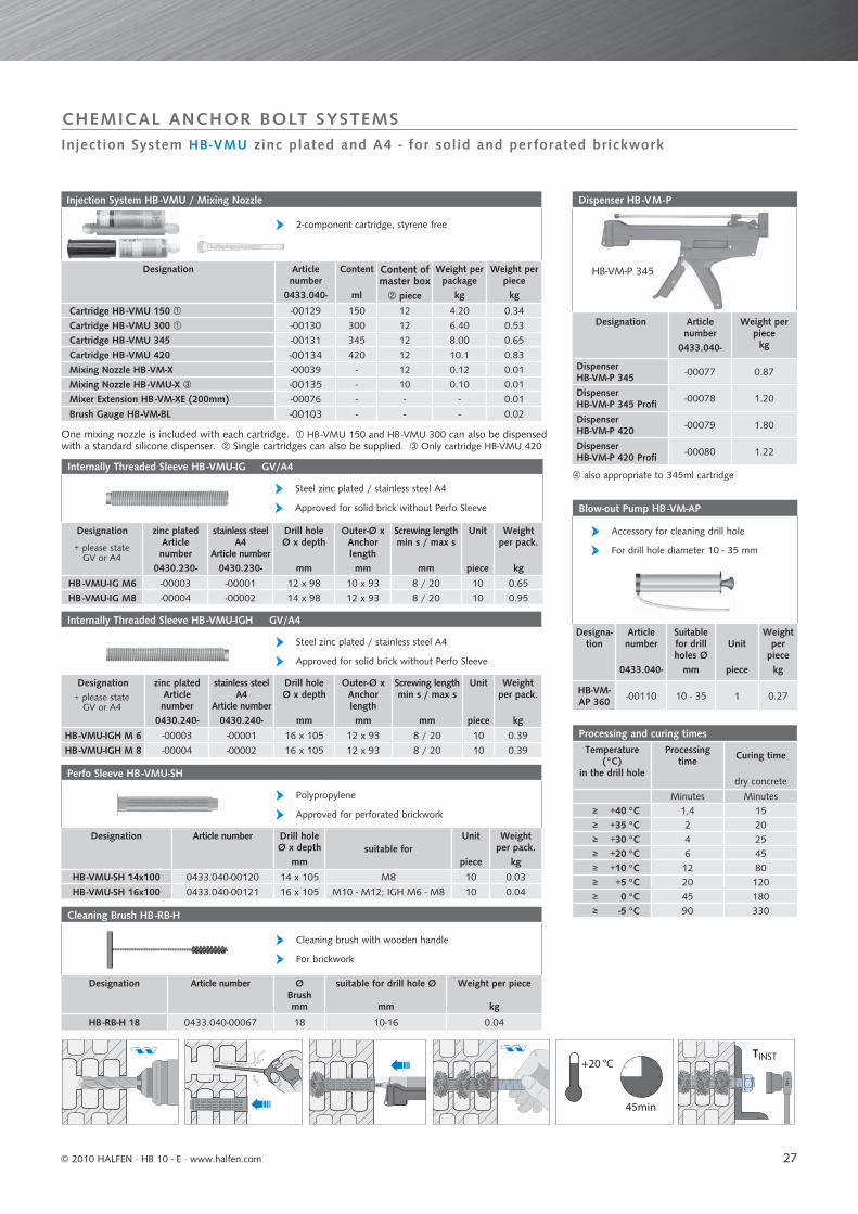
Injection System HB-VMU zinc plated and A4 - for solid and per forated brickwork
CHEMICAL ANCHOR BOLT SYSTEMS
Description
The HB-VMU Injection System is an anchorbolt system without expansion pressure forsolid and perforated brickwork. It consists ofa styrene-free vinylester resin and a hardenercomponent in a plastic cartridge. The ancho-ring element can be a threaded stud or an internally threaded sleeve. Using the HB-VM-P
Perfo Sleeve HB -VMU-SH
Cartridge HB -VMU 345
Cartridge HB -VMU 300
Cartridge HB -VMU 420
Cartridge HB -VMU 150
Anchor Stud HB -VMU-A GV or A4
Anchor Stud HB -VMU-AH GV or A4
Internal Threaded Sleeve HB -VMU-IG GV or A4
Internal Threaded Sleeve HB -VMU-IGH GV or A4
Dispenser, the components are injected through the HB-VM-X Static Mixer intothe drill hole (solid bricks) or the Perfo Sleeve(perforated bricks). The threaded stud or slee-ve with internal thread are manually inserted into the drill hole. The injection adhesive will cure and bond the anchored element securely to the backing structure.
Applications
For anchoring in perforated brickwork in dryinternal walls, with A4 also in the open or indamp rooms without aggressive conditions:canopies, door and window frames, façadesubstructures, battening.
Load range: 0,3 kN - 1,7 kN
© 2010 HALFEN · HB 10 - E ⋅ www.halfen.com
27
Internally Threaded Sleeve HB -VMU-IGH GV/A4
Steel zinc plated / stainless steel A4
Approved for solid brick without Perfo Sleeve
Designation zinc platedArticle number
0430.240-
stainless steel A4
Article number0430.240-
Drill holeØ x depth
mm
Outer-Ø x Anchor lengthmm
Screwing lengthmin s / max s
mm
Unit
piece
Weight per pack.
kg
HB -VMU-IGH M 6 -00003 -00001 16 x 105 12 x 93 8 / 20 10 0.39
HB -VMU-IGH M 8 -00004 -00002 16 x 105 12 x 93 8 / 20 10 0.39
Perfo Sleeve HB -VMU-SH
Polypropylene
Approved for perforated brickwork
Designation Article number Drill holeØ x depth
mmsuitable for
Unit
piece
Weight per pack.
kg
HB -VMU-SH 14x100 0433.040-00120 14 x 105 M8 10 0.03
HB -VMU-SH 16x100 0433.040-00121 16 x 105 M10 - M12; IGH M6 - M8 10 0.04
Cleaning Brush HB -RB-H
Cleaning brush with wooden handle
For brickwork
Designation Article number ØBrushmm
suitable for drill hole Ø
mm
Weight per piece
kg
HB -RB-H 18 0433.040-00067 18 10-16 0.04
Injection System HB -VMU / Mixing Nozzle
2-component cartridge, styrene free
Designation Article number
0433.040-
Content
ml
Content of master box
piece
Weight per package
kg
Weight per piecekg
Cartridge HB -VMU 150 -00129 150 12 4.20 0.34
Cartridge HB -VMU 300 -00130 300 12 6.40 0.53
Cartridge HB -VMU 345 -00131 345 12 8.00 0.65
Cartridge HB -VMU 420 -00134 420 12 10.1 0.83
Mixing Nozzle HB -VM-X -00039 - 12 0.12 0.01
Mixing Nozzle HB -VMU-X -00135 - 10 0.10 0.01
Mixer Extension HB -VM-XE (200mm) -00076 - - - 0.01
Brush Gauge HB -VM-BL -00103 - - - 0.02
Blow-out Pump HB -VM-AP
Accessory for cleaning drill hole
For drill hole diameter 10 - 35 mm
Designa-tion
Article number
0433.040-
Suitable for drill holes Ø
mm
Unit
piece
Weight per
piecekg
HB-VM-AP 360 -00110 10 - 35 1 0.27
Internally Threaded Sleeve HB -VMU-IG GV/A4
Steel zinc plated / stainless steel A4
Approved for solid brick without Perfo Sleeve
Designation zinc platedArticle number
0430.230-
stainless steel A4
Article number0430.230-
Drill holeØ x depth
mm
Outer-Ø x Anchor lengthmm
Screwing lengthmin s / max s
mm
Unit
piece
Weight per pack.
kg
HB -VMU-IG M6 -00003 -00001 12 x 98 10 x 93 8 / 20 10 0.65
HB -VMU-IG M8 -00004 -00002 14 x 98 12 x 93 8 / 20 10 0.95
+ please stateGV or A4
+ please stateGV or A4
Processing and curing timesTemperature
(°C)in the drill hole
Processing time Curing time
dry concrete
Minutes Minutes≥ +40 °C 1,4 15≥ +35 °C 2 20≥ +30 °C 4 25≥ +20 °C 6 45≥ +10 °C 12 80≥ +5 °C 20 120≥ 0 °C 45 180≥ -5 °C 90 330
Dispenser HB -VM-P
Designation Article number
0433.040-
Weight per piece kg
Dispenser HB-VM-P 345 -00077 0.87
Dispenser HB-VM-P 345 Profi -00078 1.20
Dispenser HB-VM-P 420 -00079 1.80
Dispenser HB-VM-P 420 Profi -00080 1.22
45min
+20 °C
Nm
TINST
Injection System HB-VMU zinc plated and A4 - for solid and per forated brickwork
CHEMICAL ANCHOR BOLT SYSTEMS
One mixing nozzle is included with each cartridge. HB -VMU 150 and HB -VMU 300 can also be dispensed with a standard silicone dispenser. Single cartridges can also be supplied. Only cartridge HB-VMU 420
also appropriate to 345ml cartridge
HB-VM-P 345
© 2010 HALFEN · HB 10 - E · www.halfen.com

28
Approved loads for tension, shear anddiagonal tension for all angles(HB -VMU-AM8-M12; HB -VMU-IG M6-M8)
Solid brick
Solid sand/lime
Vertical perforated brick Perforated sand/lime brick
Hollow core ae-rated concrete
Hollow core concrete
Mz 12 KS 12 HLz 4 HLz 6 HLz 12 KSL 4 KSL 6 KSL 12 Hbl 2 Hbl 4 Hbn 4Drilling with rotation only [kN] 1.7 1.7 0.6 0.8 1.0 0.6 0.8 1.4 0.5 0.8 0.8
Drilling with hammer action [kN] 1.7 1.7 0.3 0.4 0.8 0.4 0.6 0.8 0.3 0.6 0.6
Extract from Admissible Service Conditions of Z-21.3-1853
Loads and performance data Injection System HB -VMU
HB -VMU-A HB -VMU-AH HB -VMU-IG/VMU-IGHM 8 M 10 M 12 M 12 M 6 M8
Approved bending moment (steel zinc plated) appr. M [Nm] 11.0 21.0 37.0 37.0 4.4 11.0
Approved bending moment (stainless steel A4) appr. M [Nm] 12.0 24.0 42.0 42.0 4.9 12.0
Approved bending moment (stainless steel HCR 1.4529) appr. M [Nm] 9.4 19.0 33.0 33.0 4.9 9.4
Spacing and edge distanceEffective anchorage depth hef [mm] 80 90 93 93 93 93
Spacing (anchor group) a ≥ [mm] 100 (200)
Minimum spacing min a [mm] 50
Minimum distance between anchors (individual anchors) az [mm] 250
Edge distance ar ≥ [mm] 200 (250)
Edge distance under special conditions ar [mm] 50 (60)
Minimum thickness of building component (brickwork) hmin [mm] 110
Installation parameters
Screwing depth of screw/threaded stud min s [mm] - - - - 8 8
max s [mm] - - - - 20 20
Drill hole diameter with Perfo Sleeve do [mm] 14 16 - 16 16 16
Drill hole diameter with Perfo Sleeve (solid brick) do [mm] 10 12 14 - 12 14
Diameter of clearance hole in the fixture df [mm] 9 12 14 14 7 9
Depth of drill hole with Perfo Sleeve h0 [mm] 105 105 - 105 105 105
Depth of drill hole without Perfo Sleeve (solid brick) h0 [mm] 85 95 98 - 98 98
Installation torque Tinst [Nm] 8 8 8 8 8 8
Diameter of Cleaning Brush dB [mm] 18 18 18 18 18 18
Adhesive required per drill hole with (scaling) VMU 300 / VMU 345 Perfo Sleeve [mm] 10/9 13/12 - 13/12 13/12 13/12
Adhesive required per drill hole with Perfo Sleeve [ml] 15.0 21.0 - 21.0 21.0 21.0
Adhesive required per drill hole without (scaling) VMU 300 / VMU 345 Perfo Sleeve [mm] 4/3 5/4 7/6 - 5/4 6/5
Adhesive required per drill hole without Perfo Sleeve [ml] 5.2 7.3 9.8 - 7.3 9.8
Drill holes per Cartridge with VMU 300 / VMU 345 Perfo Sleeve [piece] 17/20 12/14 - 12/14 12/14 12/14
Drill holes per Cartridge without VMU 300 / VMU 345 Perfo Sleeve [piece] 50/58 35/41 26/31 - 35/41 26/31
Maximum loads for each block ≤ 3 DF 4 to 10 DF ≥ 10 DF
without imposed load max. F [kN] 1.0 1.4 2.0
with imposed load max. F [kN] 1.4 1.7 2.5
ho
hef
≥ hmin
tfi x
M
≥ hmin
ho
hef tfi x
d0
Z-21.3-1853
Injection System HB-VMU zinc plated and A4 - for solid and per forated brickwork
CHEMICAL ANCHOR BOLT SYSTEMS
The spacings of pairs of anchors and groups of 4 anchors can be reduced to the minimumvalue, if the permitted loads are reduced. This does not apply to Hbl and Hbn brickwork. Themaximum loads for each individual block must not be exceeded (see approval Z-21.3-1853).
Value in brackets for Hbl (Hollow block concrete, according to DIN 18151) and Hbn (Hollow
Extract from Admissible Service Conditions of Z-21.3-1853Approved loads for anchors without influence of spacing and edge distance.
Outer web ≥ 30mm
Installation in perforated bricks: with Perfo Sleeve
Installation in solid bricks:without Perfo Sleeve
HB-VMU-Perfo Sleeve
to fit
- A M8 SH 14
- A M10 SH 16
- AH M12 SH 16
- IGH M6 SH 16
- IGH M8 SH 16
HB-VMU-
- A M8
- A M10
- A M12
- IG M6
- IG M8
block concrete, DIN 18153) min a does not apply to Hbl and Hbn brickwork Value in brackets applies to use in solid brick. 2 Nm if anchor plate is not seated solidly on surface of base material.
© 2010 HALFEN · HB 10 - E ⋅ www.halfen.com
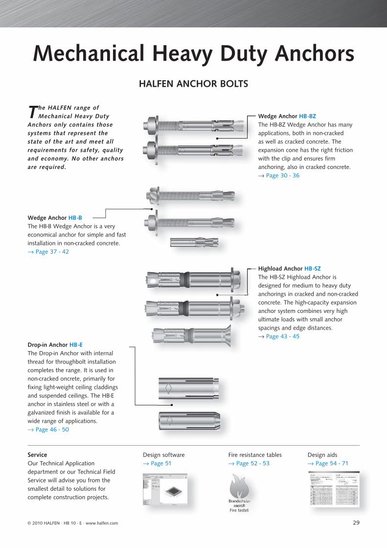
29
Mechanical Heavy Duty AnchorsHALFEN ANCHOR BOLTS
Wedge Anchor HB -BThe HB-B Wedge Anchor is a veryeconomical anchor for simple and fastinstallation in non-cracked concrete.→ Page 37 - 42
The HALFEN range of Mechanical Heavy Duty
Anchors only contains those systems that represent the state of the art and meet all requirements for safety, quality and economy. No other anchors are required.
Wedge Anchor HB -BZThe HB-BZ Wedge Anchor has manyapplications, both in non-crackedas well as cracked concrete. Theexpansion cone has the right frictionwith the clip and ensures fi rmanchoring, also in cracked concrete.→ Page 30 - 36
Highload Anchor HB -SZThe HB-SZ Highload Anchor is designed for medium to heavy duty anchorings in cracked and non-cracked concrete. The high-capacity expansion anchor system combines very high ultimate loads with small anchor spacings and edge distances.→ Page 43 - 45
Drop-in Anchor HB -EThe Drop-in Anchor with internalthread for throughbolt installationcompletes the range. It is used in non-cracked oncrete, primarily for fi xing light-weight ceiling claddings and suspended ceilings. The HB-E anchor in stainless steel or with a galvanized fi nish is available for a wide range of applications. → Page 46 - 50
ServiceOur Technical Applicationdepartment or our Technical FieldService will advise you from thesmallest detail to solutions forcomplete construction projects.
Design software → Page 51
Fire resistance tables → Page 52 - 53
Design aids→ Page 54 - 71
Fire testet
© 2010 HALFEN · HB 10 - E · www.halfen.com
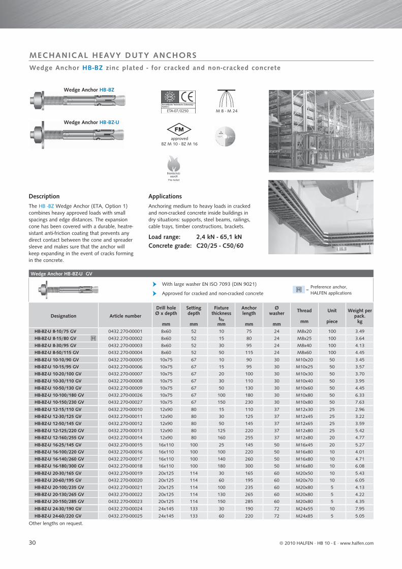
30
Wedge Anchor HB -BZ-U GV
With large washer EN ISO 7093 (DIN 9021)
Approved for cracked and non-cracked concrete
Designation Article number
Drill holeØ x depth
mm
Setting depth
mm
Fixture thickness
tfixmm
Anchor length
mm
Ø washer
mm
Thread
mm
Unit
piece
Weight per pack.
kg
HB-BZ-U 8-10/75 GV 0432.270-00001 8x60 52 10 75 24 M8x20 100 3.49
HB-BZ-U 8-15/80 GV 0432.270-00002 8x60 52 15 80 24 M8x25 100 3.64
HB-BZ-U 8-30/95 GV 0432.270-00003 8x60 52 30 95 24 M8x40 100 4.13
HB-BZ-U 8-50/115 GV 0432.270-00004 8x60 52 50 115 24 M8x60 100 4.45
HB-BZ-U 10-10/90 GV 0432.270-00005 10x75 67 10 90 30 M10x20 50 3.45
HB-BZ-U 10-15/95 GV 0432.270-00006 10x75 67 15 95 30 M10x25 50 3.57
HB-BZ-U 10-20/100 GV 0432.270-00007 10x75 67 20 100 30 M10x30 50 3.70
HB-BZ-U 10-30/110 GV 0432.270-00008 10x75 67 30 110 30 M10x40 50 3.95
HB-BZ-U 10-50/130 GV 0432.270-00009 10x75 67 50 130 30 M10x60 50 4.45
HB-BZ-U 10-100/180 GV 0432.270-00026 10x75 67 100 180 30 M10x80 50 6.33
HB-BZ-U 10-150/230 GV 0432.270-00027 10x75 67 150 230 30 M10x80 50 7.63
HB-BZ-U 12-15/110 GV 0432.270-00010 12x90 80 15 110 37 M12x30 25 2.96
HB-BZ-U 12-30/125 GV 0432.270-00011 12x90 80 30 125 37 M12x45 25 3.22
HB-BZ-U 12-50/145 GV 0432.270-00012 12x90 80 50 145 37 M12x65 25 3.59
HB-BZ-U 12-125/220 GV 0432.270-00013 12x90 80 125 220 37 M12x80 25 5.42
HB-BZ-U 12-160/255 GV 0432.270-00014 12x90 80 160 255 37 M12x80 20 4.77
HB-BZ-U 16-25/145 GV 0432.270-00015 16x110 100 25 145 50 M16x45 20 5.27
HB-BZ-U 16-100/220 GV 0432.270-00016 16x110 100 100 220 50 M16x80 10 4.01
HB-BZ-U 16-140/260 GV 0432.270-00017 16x110 100 140 260 50 M16x80 10 4.71
HB-BZ-U 16-180/300 GV 0432.270-00018 16x110 100 180 300 50 M16x80 10 6.08
HB-BZ-U 20-30/165 GV 0432.270-00019 20x125 114 30 165 60 M20x50 10 5.43
HB-BZ-U 20-60/195 GV 0432.270-00020 20x125 114 60 195 60 M20x70 10 6.05
HB-BZ-U 20-100/235 GV 0432.270-00021 20x125 114 100 235 60 M20x80 5 4.13
HB-BZ-U 20-130/265 GV 0432.270-00022 20x125 114 130 265 60 M20x80 5 4.22
HB-BZ-U 20-150/285 GV 0432.270-00023 20x125 114 150 285 60 M20x80 5 4.35
HB-BZ-U 24-30/190 GV 0432.270-00024 24x145 133 30 190 72 M24x55 10 7.95
HB-BZ-U 24-60/220 GV 0432.270-00025 24x145 133 60 220 72 M24x85 5 5.05
Other lengths on request.
ETA-07/02501
Wedge Anchor HB-BZ zinc plated - for cracked and non-cracked concrete
MECHANICAL HEAVY DUTY ANCHORS
Wedge Anchor HB -BZ
Wedge Anchor HB -BZ-U
Description
The HB -BZ Wedge Anchor (ETA, Option 1)combines heavy approved loads with smallspacings and edge distances. The expansioncone has been covered with a durable, heatre-sistant anti-friction coating that prevents any direct contact between the cone and spreader sleeve and makes sure that the anchor will keep expanding in the event of cracks forming in the concrete.
Applications
Anchoring medium to heavy loads in crackedand non-cracked concrete inside buildings indry situations: supports, steel beams, railings,cable trays, timber constructions, brackets.
Load range: 2,4 kN - 65,1 kNConcrete grade: C20/25 - C50/60
M 8 - M 24
approvedBZ M 10 - BZ M 16
Preference anchor, HALFEN applications
=
Fire testet
© 2010 HALFEN · HB 10 - E ⋅ www.halfen.com
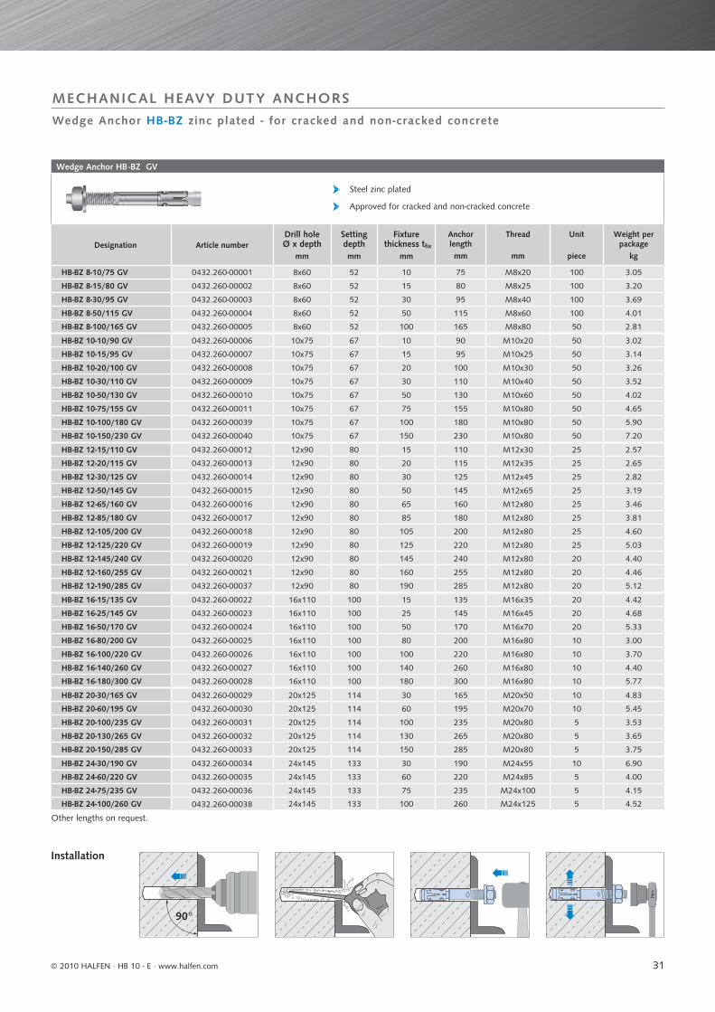
31
Wedge Anchor HB -BZ GV
Steel zinc plated
Approved for cracked and non-cracked concrete
Designation Article numberDrill holeØ x depth
mm
Setting depthmm
Fixture thickness tfix
mm
Anchor length mm
Thread
mm
Unit
piece
Weight per package
kg
HB-BZ 8-10/75 GV 0432.260-00001 8x60 52 10 75 M8x20 100 3.05
HB-BZ 8-15/80 GV 0432.260-00002 8x60 52 15 80 M8x25 100 3.20
HB-BZ 8-30/95 GV 0432.260-00003 8x60 52 30 95 M8x40 100 3.69
HB-BZ 8-50/115 GV 0432.260-00004 8x60 52 50 115 M8x60 100 4.01
HB-BZ 8-100/165 GV 0432.260-00005 8x60 52 100 165 M8x80 50 2.81
HB-BZ 10-10/90 GV 0432.260-00006 10x75 67 10 90 M10x20 50 3.02
HB-BZ 10-15/95 GV 0432.260-00007 10x75 67 15 95 M10x25 50 3.14
HB-BZ 10-20/100 GV 0432.260-00008 10x75 67 20 100 M10x30 50 3.26
HB-BZ 10-30/110 GV 0432.260-00009 10x75 67 30 110 M10x40 50 3.52
HB-BZ 10-50/130 GV 0432.260-00010 10x75 67 50 130 M10x60 50 4.02
HB-BZ 10-75/155 GV 0432.260-00011 10x75 67 75 155 M10x80 50 4.65
HB-BZ 10-100/180 GV 0432.260-00039 10x75 67 100 180 M10x80 50 5.90
HB-BZ 10-150/230 GV 0432.260-00040 10x75 67 150 230 M10x80 50 7.20
HB-BZ 12-15/110 GV 0432.260-00012 12x90 80 15 110 M12x30 25 2.57
HB-BZ 12-20/115 GV 0432.260-00013 12x90 80 20 115 M12x35 25 2.65
HB-BZ 12-30/125 GV 0432.260-00014 12x90 80 30 125 M12x45 25 2.82
HB-BZ 12-50/145 GV 0432.260-00015 12x90 80 50 145 M12x65 25 3.19
HB-BZ 12-65/160 GV 0432.260-00016 12x90 80 65 160 M12x80 25 3.46
HB-BZ 12-85/180 GV 0432.260-00017 12x90 80 85 180 M12x80 25 3.81
HB-BZ 12-105/200 GV 0432.260-00018 12x90 80 105 200 M12x80 25 4.60
HB-BZ 12-125/220 GV 0432.260-00019 12x90 80 125 220 M12x80 25 5.03
HB-BZ 12-145/240 GV 0432.260-00020 12x90 80 145 240 M12x80 20 4.40
HB-BZ 12-160/255 GV 0432.260-00021 12x90 80 160 255 M12x80 20 4.46
HB-BZ 12-190/285 GV 0432.260-00037 12x90 80 190 285 M12x80 20 5.12
HB-BZ 16-15/135 GV 0432.260-00022 16x110 100 15 135 M16x35 20 4.42
HB-BZ 16-25/145 GV 0432.260-00023 16x110 100 25 145 M16x45 20 4.68
HB-BZ 16-50/170 GV 0432.260-00024 16x110 100 50 170 M16x70 20 5.33
HB-BZ 16-80/200 GV 0432.260-00025 16x110 100 80 200 M16x80 10 3.00
HB-BZ 16-100/220 GV 0432.260-00026 16x110 100 100 220 M16x80 10 3.70
HB-BZ 16-140/260 GV 0432.260-00027 16x110 100 140 260 M16x80 10 4.40
HB-BZ 16-180/300 GV 0432.260-00028 16x110 100 180 300 M16x80 10 5.77
HB-BZ 20-30/165 GV 0432.260-00029 20x125 114 30 165 M20x50 10 4.83
HB-BZ 20-60/195 GV 0432.260-00030 20x125 114 60 195 M20x70 10 5.45
HB-BZ 20-100/235 GV 0432.260-00031 20x125 114 100 235 M20x80 5 3.53
HB-BZ 20-130/265 GV 0432.260-00032 20x125 114 130 265 M20x80 5 3.65
HB-BZ 20-150/285 GV 0432.260-00033 20x125 114 150 285 M20x80 5 3.75
HB-BZ 24-30/190 GV 0432.260-00034 24x145 133 30 190 M24x55 10 6.90
HB-BZ 24-60/220 GV 0432.260-00035 24x145 133 60 220 M24x85 5 4.00
HB-BZ 24-75/235 GV 0432.260-00036 24x145 133 75 235 M24x100 5 4.15
HB-BZ 24-100/260 GV 0432.260-00038 24x145 133 100 260 M24x125 5 4.52
Other lengths on request.
Nm
90°
Wedge Anchor HB-BZ zinc plated - for cracked and non-cracked concrete
MECHANICAL HEAVY DUTY ANCHORS
Installation
© 2010 HALFEN · HB 10 - E · www.halfen.com
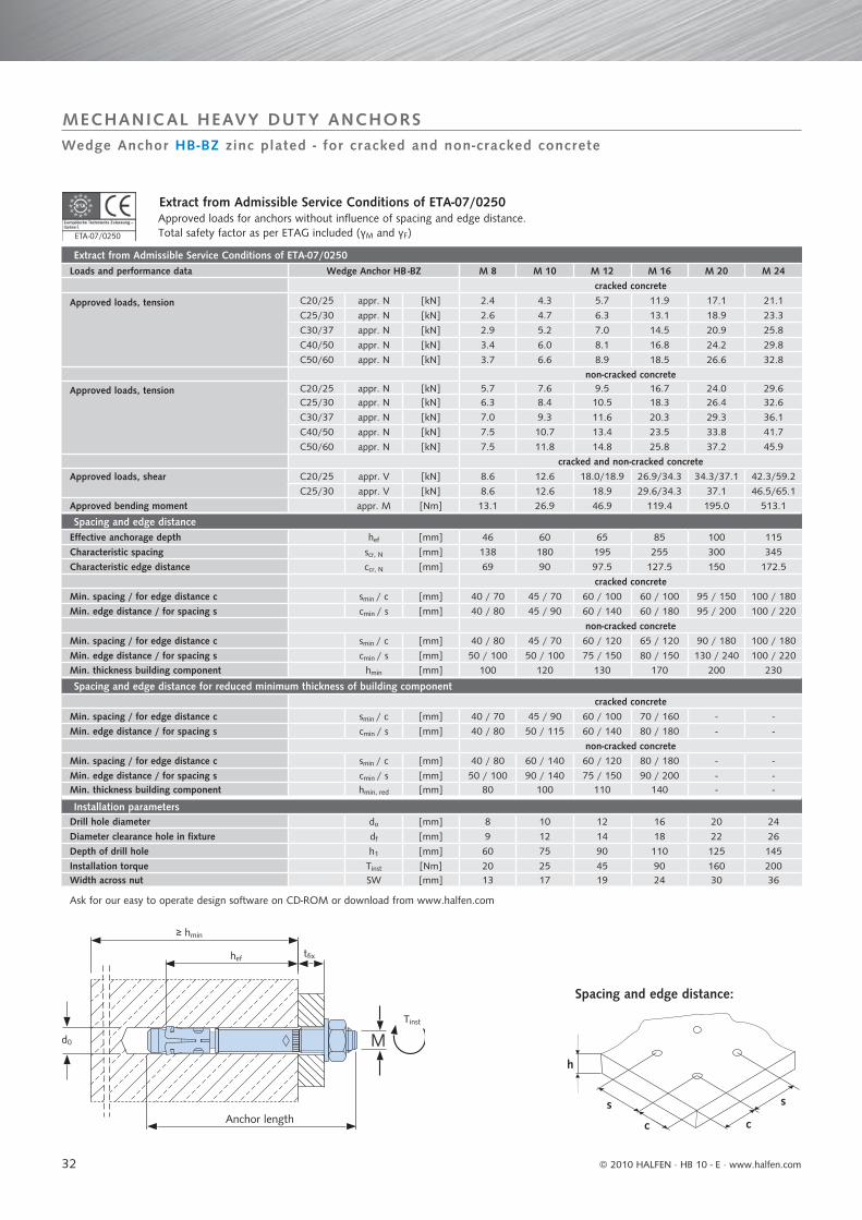
32
Extract from Admissible Service Conditions of ETA-07/0250Loads and performance data Wedge Anchor HB -BZ M 8 M 10 M 12 M 16 M 20 M 24
cracked concrete
Approved loads, tension C20/25 appr. N [kN] 2.4 4.3 5.7 11.9 17.1 21.1
C25/30 appr. N [kN] 2.6 4.7 6.3 13.1 18.9 23.3
C30/37 appr. N [kN] 2.9 5.2 7.0 14.5 20.9 25.8
C40/50 appr. N [kN] 3.4 6.0 8.1 16.8 24.2 29.8
C50/60 appr. N [kN] 3.7 6.6 8.9 18.5 26.6 32.8
non-cracked concrete
Approved loads, tension C20/25 appr. N [kN] 5.7 7.6 9.5 16.7 24.0 29.6C25/30 appr. N [kN] 6.3 8.4 10.5 18.3 26.4 32.6
C30/37 appr. N [kN] 7.0 9.3 11.6 20.3 29.3 36.1
C40/50 appr. N [kN] 7.5 10.7 13.4 23.5 33.8 41.7
C50/60 appr. N [kN] 7.5 11.8 14.8 25.8 37.2 45.9
cracked and non-cracked concrete
Approved loads, shear C20/25 appr. V [kN] 8.6 12.6 18.0/18.9 26.9/34.3 34.3/37.1 42.3/59.2
C25/30 appr. V [kN] 8.6 12.6 18.9 29.6/34.3 37.1 46.5/65.1
Approved bending moment appr. M [Nm] 13.1 26.9 46.9 119.4 195.0 513.1
Spacing and edge distanceEffective anchorage depth hef [mm] 46 60 65 85 100 115
Characteristic spacing scr, N [mm] 138 180 195 255 300 345
Characteristic edge distance ccr, N [mm] 69 90 97.5 127.5 150 172.5
cracked concreteMin. spacing / for edge distance c smin / c [mm] 40 / 70 45 / 70 60 / 100 60 / 100 95 / 150 100 / 180
Min. edge distance / for spacing s cmin / s [mm] 40 / 80 45 / 90 60 / 140 60 / 180 95 / 200 100 / 220
non-cracked concreteMin. spacing / for edge distance c smin / c [mm] 40 / 80 45 / 70 60 / 120 65 / 120 90 / 180 100 / 180
Min. edge distance / for spacing s cmin / s [mm] 50 / 100 50 / 100 75 / 150 80 / 150 130 / 240 100 / 220
Min. thickness building component hmin [mm] 100 120 130 170 200 230
Spacing and edge distance for reduced minimum thickness of building componentcracked concrete
Min. spacing / for edge distance c smin / c [mm] 40 / 70 45 / 90 60 / 100 70 / 160 - -
Min. edge distance / for spacing s cmin / s [mm] 40 / 80 50 / 115 60 / 140 80 / 180 - -
non-cracked concreteMin. spacing / for edge distance c smin / c [mm] 40 / 80 60 / 140 60 / 120 80 / 180 - -
Min. edge distance / for spacing s cmin / s [mm] 50 / 100 90 / 140 75 / 150 90 / 200 - -Min. thickness building component hmin, red [mm] 80 100 110 140 - -
Installation parametersDrill hole diameter do [mm] 8 10 12 16 20 24
Diameter clearance hole in fixture df [mm] 9 12 14 18 22 26
Depth of drill hole h1 [mm] 60 75 90 110 125 145
Installation torque Tinst [Nm] 20 25 45 90 160 200Width across nut SW [mm] 13 17 19 24 30 36
Ask for our easy to operate design software on CD-ROM or download from www.halfen.com
Tinst
M
≥ hmin
hef
d0
tfix
s
cc
h
s
ETA-07/02501
Wedge Anchor HB-BZ zinc plated - for cracked and non-cracked concrete
MECHANICAL HEAVY DUTY ANCHORS
Extract from Admissible Service Conditions of ETA-07/0250Approved loads for anchors without influence of spacing and edge distance.Total safety factor as per ETAG included (γM and γF)
Anchor length
Spacing and edge distance:
© 2010 HALFEN · HB 10 - E ⋅ www.halfen.com
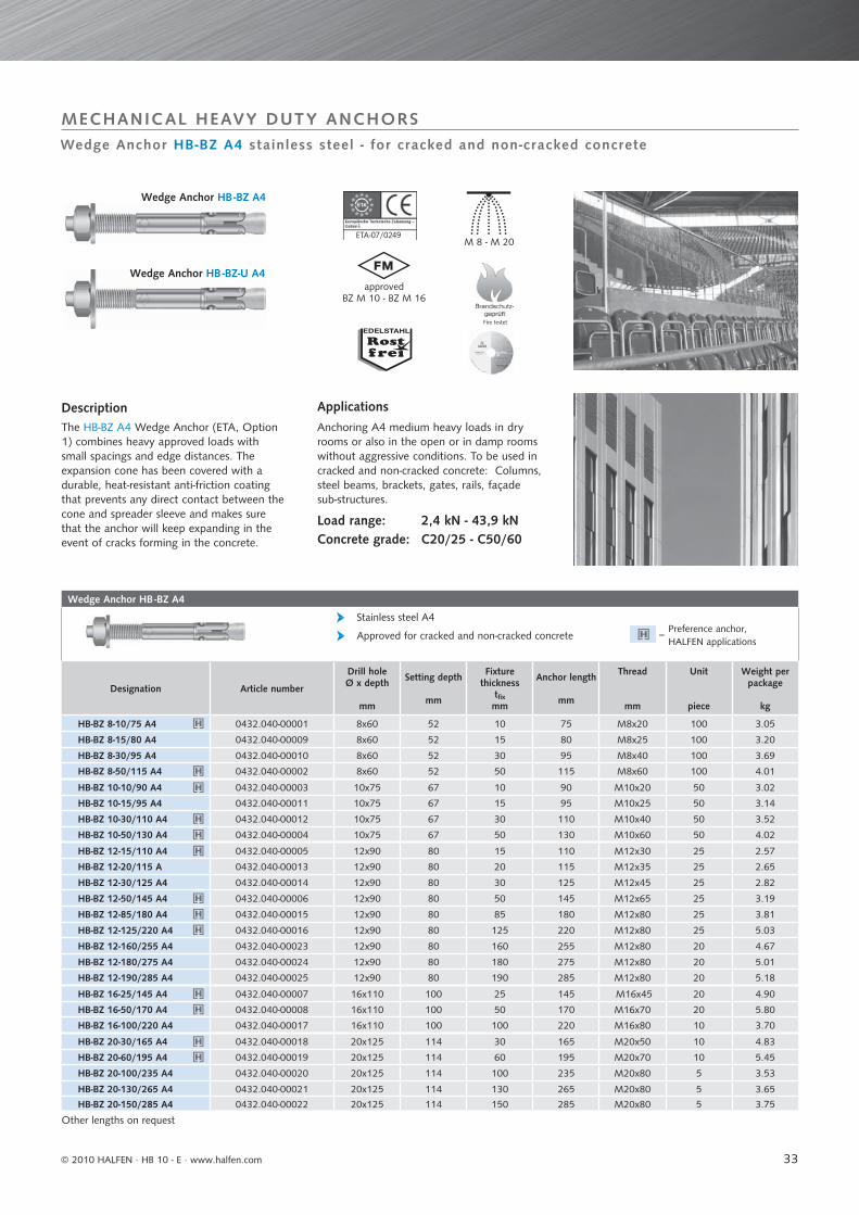
33
Wedge Anchor HB -BZ A4
Designation Article number
Drill holeØ x depth
mm
Setting depth
mm
Fixture thickness
tfixmm
Anchor length
mm
Thread
mm
Unit
piece
Weight per package
kg
HB-BZ 8-10/75 A4 0432.040-00001 8x60 52 10 75 M8x20 100 3.05
HB-BZ 8-15/80 A4 0432.040-00009 8x60 52 15 80 M8x25 100 3.20
HB-BZ 8-30/95 A4 0432.040-00010 8x60 52 30 95 M8x40 100 3.69
HB-BZ 8-50/115 A4 0432.040-00002 8x60 52 50 115 M8x60 100 4.01
HB-BZ 10-10/90 A4 0432.040-00003 10x75 67 10 90 M10x20 50 3.02
HB-BZ 10-15/95 A4 0432.040-00011 10x75 67 15 95 M10x25 50 3.14
HB-BZ 10-30/110 A4 0432.040-00012 10x75 67 30 110 M10x40 50 3.52
HB-BZ 10-50/130 A4 0432.040-00004 10x75 67 50 130 M10x60 50 4.02
HB-BZ 12-15/110 A4 0432.040-00005 12x90 80 15 110 M12x30 25 2.57
HB-BZ 12-20/115 A 0432.040-00013 12x90 80 20 115 M12x35 25 2.65
HB-BZ 12-30/125 A4 0432.040-00014 12x90 80 30 125 M12x45 25 2.82
HB-BZ 12-50/145 A4 0432.040-00006 12x90 80 50 145 M12x65 25 3.19
HB-BZ 12-85/180 A4 0432.040-00015 12x90 80 85 180 M12x80 25 3.81
HB-BZ 12-125/220 A4 0432.040-00016 12x90 80 125 220 M12x80 25 5.03
HB-BZ 12-160/255 A4 0432.040-00023 12x90 80 160 255 M12x80 20 4.67
HB-BZ 12-180/275 A4 0432.040-00024 12x90 80 180 275 M12x80 20 5.01
HB-BZ 12-190/285 A4 0432.040-00025 12x90 80 190 285 M12x80 20 5.18
HB-BZ 16-25/145 A4 0432.040-00007 16x110 100 25 145 M16x45 20 4.90
HB-BZ 16-50/170 A4 0432.040-00008 16x110 100 50 170 M16x70 20 5.80
HB-BZ 16-100/220 A4 0432.040-00017 16x110 100 100 220 M16x80 10 3.70
HB-BZ 20-30/165 A4 0432.040-00018 20x125 114 30 165 M20x50 10 4.83
HB-BZ 20-60/195 A4 0432.040-00019 20x125 114 60 195 M20x70 10 5.45
HB-BZ 20-100/235 A4 0432.040-00020 20x125 114 100 235 M20x80 5 3.53
HB-BZ 20-130/265 A4 0432.040-00021 20x125 114 130 265 M20x80 5 3.65
HB-BZ 20-150/285 A4 0432.040-00022 20x125 114 150 285 M20x80 5 3.75
Other lengths on request
Approved for cracked and non-cracked concrete
Stainless steel A4
Fire testet
M 8 - M 20
approvedBZ M 10 - BZ M 16
ETA-07/02491
Wedge Anchor HB-BZ A4 stainless steel - for cracked and non-cracked concrete
MECHANICAL HEAVY DUTY ANCHORS
DescriptionThe HB-BZ A4 Wedge Anchor (ETA, Option 1) combines heavy approved loads with small spacings and edge distances. The expansion cone has been covered with a durable, heat-resistant anti-friction coating that prevents any direct contact between the cone and spreader sleeve and makes sure that the anchor will keep expanding in the event of cracks forming in the concrete.
Wedge Anchor HB -BZ-U A4
Wedge Anchor HB -BZ A4
ApplicationsAnchoring A4 medium heavy loads in dry rooms or also in the open or in damp rooms without aggressive conditions. To be used in cracked and non-cracked concrete: Columns, steel beams, brackets, gates, rails, façade sub-structures.
Load range: 2,4 kN - 43,9 kNConcrete grade: C20/25 - C50/60
Preference anchor, HALFEN applications
=
© 2010 HALFEN · HB 10 - E · www.halfen.com
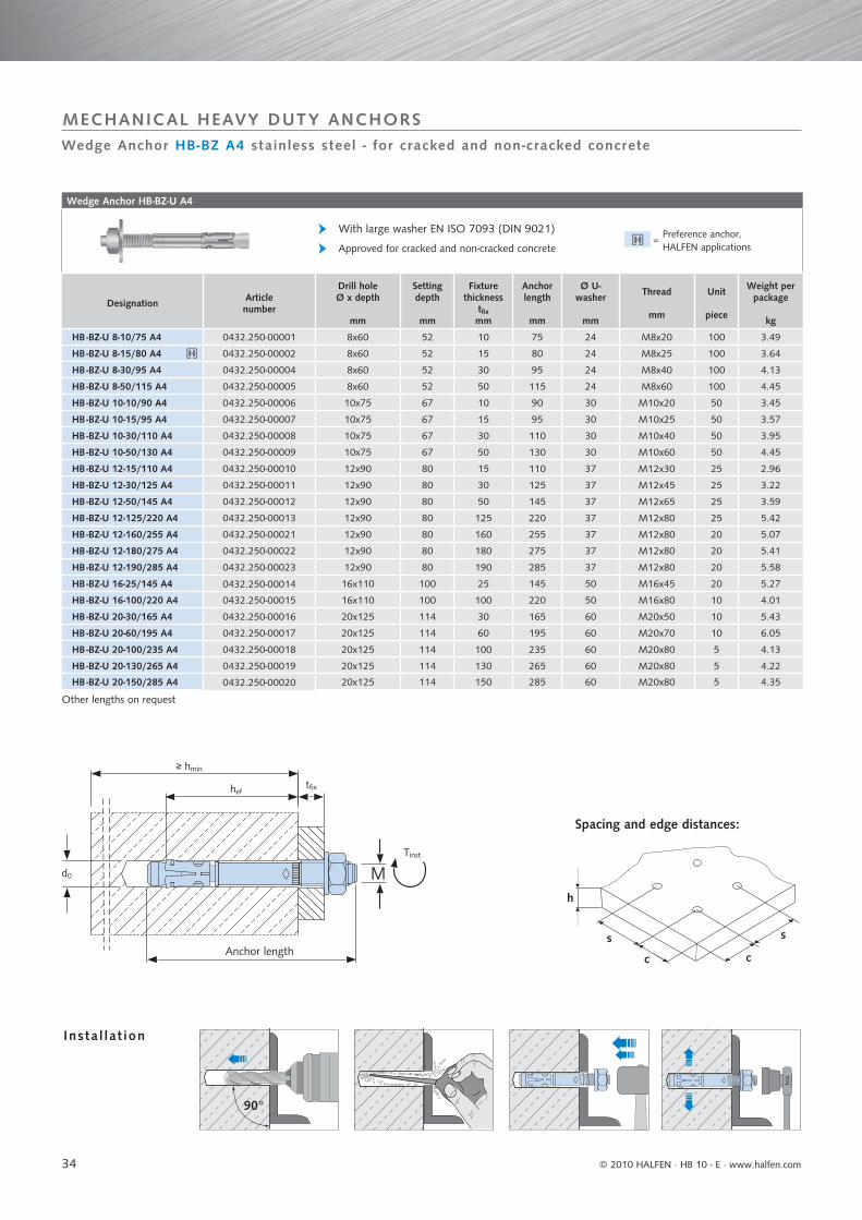
34
Wedge Anchor HB-BZ-U A4
Designation Article number
Drill holeØ x depth
mm
Setting depth
mm
Fixture thickness
tfixmm
Anchor length
mm
Ø U-washer
mm
Thread
mm
Unit
piece
Weight per package
kg
HB -BZ-U 8-10/75 A4 0432.250-00001 8x60 52 10 75 24 M8x20 100 3.49
HB -BZ-U 8-15/80 A4 0432.250-00002 8x60 52 15 80 24 M8x25 100 3.64
HB -BZ-U 8-30/95 A4 0432.250-00004 8x60 52 30 95 24 M8x40 100 4.13
HB -BZ-U 8-50/115 A4 0432.250-00005 8x60 52 50 115 24 M8x60 100 4.45
HB -BZ-U 10-10/90 A4 0432.250-00006 10x75 67 10 90 30 M10x20 50 3.45
HB -BZ-U 10-15/95 A4 0432.250-00007 10x75 67 15 95 30 M10x25 50 3.57
HB -BZ-U 10-30/110 A4 0432.250-00008 10x75 67 30 110 30 M10x40 50 3.95
HB -BZ-U 10-50/130 A4 0432.250-00009 10x75 67 50 130 30 M10x60 50 4.45
HB -BZ-U 12-15/110 A4 0432.250-00010 12x90 80 15 110 37 M12x30 25 2.96
HB -BZ-U 12-30/125 A4 0432.250-00011 12x90 80 30 125 37 M12x45 25 3.22
HB -BZ-U 12-50/145 A4 0432.250-00012 12x90 80 50 145 37 M12x65 25 3.59
HB -BZ-U 12-125/220 A4 0432.250-00013 12x90 80 125 220 37 M12x80 25 5.42
HB -BZ-U 12-160/255 A4 0432.250-00021 12x90 80 160 255 37 M12x80 20 5.07
HB -BZ-U 12-180/275 A4 0432.250-00022 12x90 80 180 275 37 M12x80 20 5.41
HB -BZ-U 12-190/285 A4 0432.250-00023 12x90 80 190 285 37 M12x80 20 5.58
HB -BZ-U 16-25/145 A4 0432.250-00014 16x110 100 25 145 50 M16x45 20 5.27
HB -BZ-U 16-100/220 A4 0432.250-00015 16x110 100 100 220 50 M16x80 10 4.01
HB -BZ-U 20-30/165 A4 0432.250-00016 20x125 114 30 165 60 M20x50 10 5.43
HB -BZ-U 20-60/195 A4 0432.250-00017 20x125 114 60 195 60 M20x70 10 6.05
HB -BZ-U 20-100/235 A4 0432.250-00018 20x125 114 100 235 60 M20x80 5 4.13
HB -BZ-U 20-130/265 A4 0432.250-00019 20x125 114 130 265 60 M20x80 5 4.22
HB -BZ-U 20-150/285 A4 0432.250-00020 20x125 114 150 285 60 M20x80 5 4.35
Other lengths on request
Approved for cracked and non-cracked concrete
With large washer EN ISO 7093 (DIN 9021)
M
s
cc
h
s
Tinst
≥ hmin
hef
d0
tfix
90°
Nm
Wedge Anchor HB-BZ A4 stainless steel - for cracked and non-cracked concrete
MECHANICAL HEAVY DUTY ANCHORS
Insta l la t ion
Preference anchor, HALFEN applications
=
Spacing and edge distances:
Anchor length
© 2010 HALFEN · HB 10 - E ⋅ www.halfen.com

35
Extract from Admissible Service Conditions of ETA-07/0249
Loads and performance data Wedge Anchor HB -BZ A4 M 8 M 10 M 12 M 16 M 20
cracked concrete
Approved loads, tension C20/25 app. N [kN] 2.4 4.3 5.7 11.9 17.1
C25/30 app. N [kN] 2.6 4.7 6.3 13.1 18.9
C30/37 app. N [kN] 2.9 5.2 7.0 14.5 20.9
C40/50 app. N [kN] 3.4 6.0 8.1 16.8 24.2
C50/60 app. N [kN] 3.7 6.6 8.9 18.5 26.6
non-cracked concrete
Approved loads, tension C20/25 app. N [kN] 5.7 7.6 9.5 16.7 24.0
C25/30 app. N [kN] 6.3 8.4 10.5 18.3 26.4
C30/37 app. N [kN] 7.0 9.3 11.6 20.3 29.3
C40/50 app. N [kN] 7.6 10.7 13.4 23.5 33.8
C50/60 app. N [kN] 7.6 11.8 14.8 25.8 37.2
cracked and non-cracked concrete
Approved loads, shear C20/25 app. V [kN] 7.4 11.4 17.1 26.9/31.4 34.3/43.9
≥ C25/30 app. V [kN] 7.4 11.4 17.1 29.6/31.4 37.7/43.9
Approved bending moment app. M [Nm] 14.9 29.7 52.6 133.1 231.6
Spacing and edge distance
Effective anchorage depth hef [mm] 46 60 65 85 100
Characteristic spacing scr. N [mm] 138 180 195 255 300
Characteristic edge distance ccr. N [mm] 69 90 97.5 127.5 150
cracked concrete
Min. spacing / for edge distance c smin / c [mm] 40 / 70 50 / 75 60 / 100 60 / 100 95 / 150
Min. edge distance / for spacing s cmin / s [mm] 40 / 80 55 / 90 60 / 140 60 / 180 95 / 200
non-cracked concrete
Min. spacing / for edge distance c smin / c [mm] 40 / 80 50 / 75 60 / 120 65 / 120 90 / 180
Min. edge distance / for spacing s cmin / s [mm] 50 / 100 60 / 120 75 / 150 80 / 150 130 / 240
Min. thickness building component hmin [mm] 100 120 130 160 200
Spacing and edge distance for reduced minimum thickness of building component
cracked concrete
Min. spacing / for edge distance c smin / c [mm] 40 / 70 45 / 90 60 / 100 70 / 160 -
Min. edge distance / for spacing s cmin / s [mm] 40 / 80 50 / 115 60 / 140 80 / 180 -
non-cracked concrete
Min. spacing / for edge distance c smin / c [mm] 40 / 80 60 / 140 60 / 120 80 / 180 -
Min. edge distance / for spacing s cmin / s [mm] 50 / 100 90 / 140 75 / 150 90 / 200 -
Min. thickness building component hmin. red [mm] 80 100 110 140 -
Installation parameters
Drill hole diameter do [mm] 8 10 12 16 20
Diameter clearance hole in fixture df [mm] 9 12 14 18 22
Depth of drill hole h1 [mm] 60 75 90 110 125
Installation torque Tinst [Nm] 20 35 50 110 200
Width across nut SW [mm] 13 17 19 24 30
Ask for our easy to operate design software on CD-ROM or download from www.halfen.com
ETA07/02491
Wedge Anchor HB-BZ A4 stainless steel - for cracked and non-cracked concrete
MECHANICAL HEAVY DUTY ANCHORS
Extract from Admissible Service Conditions of ETA-07/0249Approved loads for anchors without influence of spacing and edge distance.Total safety factor as per ETAG included (γM and γF)
© 2010 HALFEN · HB 10 - E · www.halfen.com
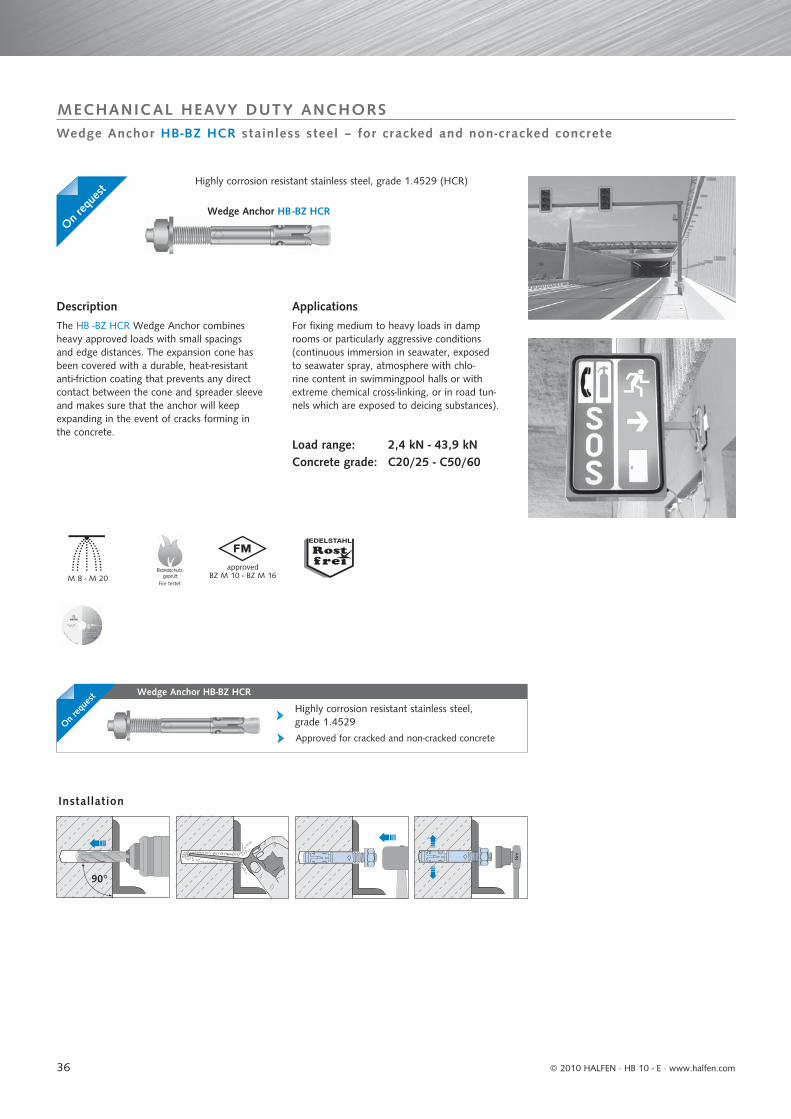
36
Wedge Anchor HB-BZ HCR
Approved for cracked and non-cracked concrete
Highly corrosion resistant stainless steel, grade 1.4529
M 8 - M 20
Nm
90°
Wedge Anchor HB-BZ HCR stainless steel – for cracked and non-cracked concrete
MECHANICAL HEAVY DUTY ANCHORS
Description
The HB -BZ HCR Wedge Anchor combines heavy approved loads with small spacings and edge distances. The expansion cone has been covered with a durable, heat-resistant anti-friction coating that prevents any direct contact between the cone and spreader sleeve and makes sure that the anchor will keep expanding in the event of cracks forming in the concrete.
Applications
For fixing medium to heavy loads in damp rooms or particularly aggressive conditions (continuous immersion in seawater, exposed to seawater spray, atmosphere with chlo-rine content in swimmingpool halls or with extreme chemical cross-linking, or in road tun-nels which are exposed to deicing substances).
Load range: 2,4 kN - 43,9 kNConcrete grade: C20/25 - C50/60
Highly corrosion resistant stainless steel, grade 1.4529 (HCR)
Wedge Anchor HB -BZ HCR
Installation
On req
uest
On req
uest
approvedBZ M 10 - BZ M 16
Fire testet
© 2010 HALFEN · HB 10 - E ⋅ www.halfen.com
37
Wedge Anchor HB -B - U G V
Steel zinc plated; with large washer EN ISO 7094 (DIN 440)
Approved for non-cracked concrete
Designation Article number Drill holeØ
mm
Drill holedepthmm
Setting depth
mm
Fixture thickness tfixmm
Anchor lengthmm
Thread
mm
Unit
piece
Weight per pack.
kg
h1 h1,red hnom hnom,red tfi x tfi x,red
HB-B-U 12-85-100/180 GV 0432.310-00001 12 90 75 80 65 85 100 180 M12x80 25 4,61
HB-B-U 12-105-120/200 GV 0432.310-00002 12 90 75 80 65 105 120 200 M12x80 25 5,06
HB-B-U 12-125-140/220 GV 0432.310-00003 12 90 75 80 65 125 140 220 M12x80 25 5,47
HB-B-U 12-145-160/240 GV 0432.310-00004 12 90 75 80 65 145 160 240 M12x80 20 4,80
HB-B-U 12-160-175/255 GV 0432.310-00005 12 90 75 80 65 160 175 255 M12x80 20 5,07
HB-B-U 12-190-205/285 GV 0432.310-00006 12 90 75 80 65 190 205 285 M12x80 20 5,62
HB-B-U 12-230-245/325 GV 0432.310-00007 12 90 75 80 65 230 245 325 M12x80 20 6,60
HB-B-U 12-260-275/355 GV 0432.310-00008 12 90 75 80 65 260 275 355 M12x80 10 3,48
HB-B-U 16-80-98/200 GV 0432.310-00009 16 110 95 98 65 80 98 200 M16x80 10 3,75
HB-B-U 16-100-118/220 GV 0432.310-00010 16 110 95 98 65 100 118 220 M16x80 10 4,07
HB-B-U 16-130-148/250 GV 0432.310-00011 16 110 95 98 65 130 148 250 M16x80 10 4,55
HB-B-U 16-165-183/285 GV 0432.310-00012 16 110 95 98 65 165 183 285 M16x80 10 5,21
HB-B-U 16-200-218/320 GV 0432.310-00013 16 110 95 98 65 200 218 320 M16x80 10 5,64
Ø Washer M12 EN ISO 7094 = 44 mm Ø Washer M16 EN ISO 7094 = 56 mm. Reduced effective anchorage depth (observe reduced loads).
M 8, M 10approved
M 10 - M 16
Nm
90°
ETA-07/02487
Wedge Anchor HB-B zinc plated steel - for non-cracked concrete
MECHANICAL HEAVY DUTY ANCHORS
Installation
Description
The HB -B Wedge Anchor (ETA option 7) is a highly efficient throughbolt for fixing suspen-ded ceilings and similar fixtures in non-cracked concrete. It combines high load-bearing capa-bilities with small anchor spacings and edge distances. There are 150 different sizes and models for a wide range of uses in medium to heavy-duty applications. Approved sizes with stainless steel expansion sleeve.
Applications
For anchoring any of the following in non -cracked concrete in dry interior rooms: suspended ceilings as per DIN 18 168 and similar fastenings (M6 – M10), supports, metal constructions, steel beams, shelf feet, pipe lines.
Load range: 2,9 kN - 37,1 kNConcrete grade: C20/25 - C50/60
Wedge Anchor HB -B Wedge Anchor HB -B-U
Fire tested
© 2010 HALFEN · HB 10 - E · www.halfen.com
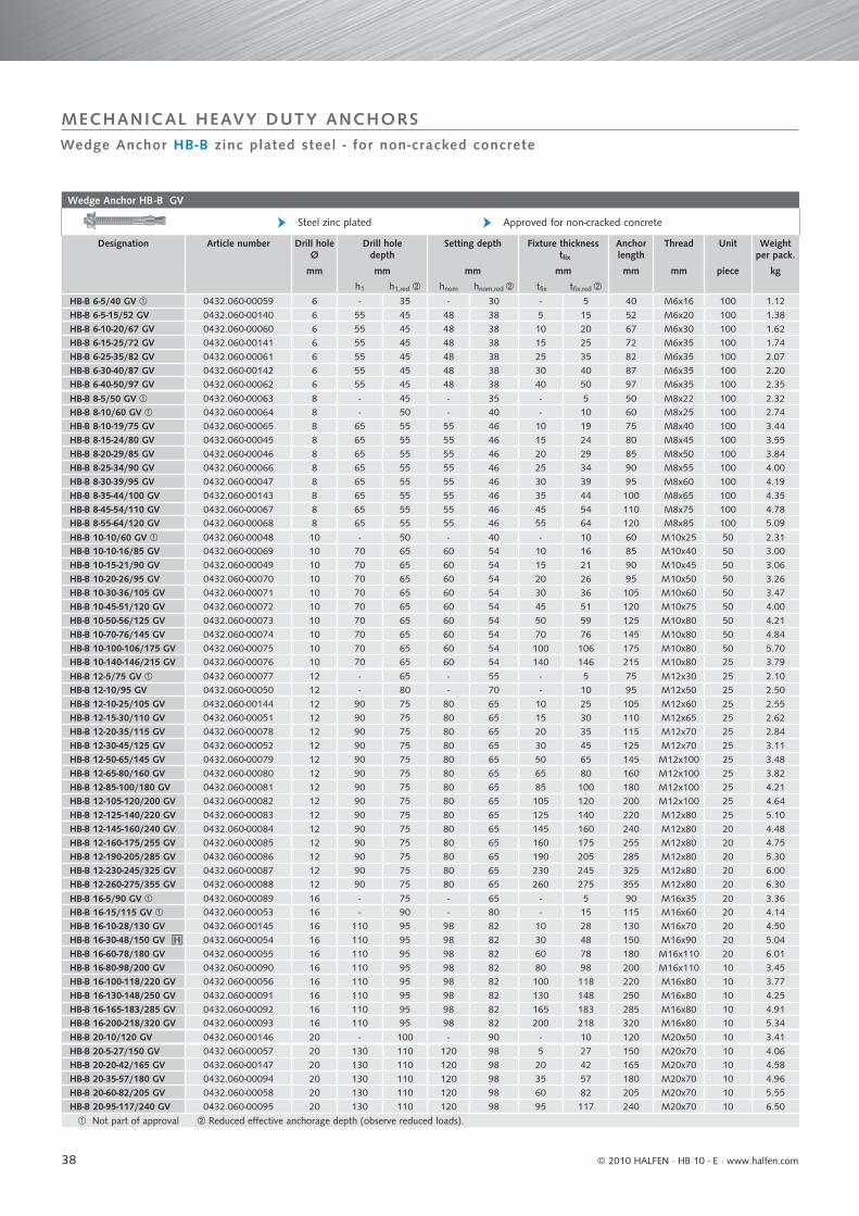
38
Wedge Anchor HB -B GV
Designation Article number Drill holeØ
mm
Drill holedepth
mm
Setting depth
mm
Fixture thickness tfixmm
Anchor length
mm
Thread
mm
Unit
piece
Weight per pack.
kg
h1 h1,red hnom hnom,red tfi x tfi x,red
HB-B 6-5/40 GV 0432.060-00059 6 - 35 - 30 - 5 40 M6x16 100 1.12HB-B 6-5-15/52 GV 0432.060-00140 6 55 45 48 38 5 15 52 M6x20 100 1.38HB-B 6-10-20/67 GV 0432.060-00060 6 55 45 48 38 10 20 67 M6x30 100 1.62HB-B 6-15-25/72 GV 0432.060-00141 6 55 45 48 38 15 25 72 M6x35 100 1.74HB-B 6-25-35/82 GV 0432.060-00061 6 55 45 48 38 25 35 82 M6x35 100 2.07HB-B 6-30-40/87 GV 0432.060-00142 6 55 45 48 38 30 40 87 M6x35 100 2.20HB-B 6-40-50/97 GV 0432.060-00062 6 55 45 48 38 40 50 97 M6x35 100 2.35
HB-B 8-5/50 GV 0432.060-00063 8 - 45 - 35 - 5 50 M8x22 100 2.32HB-B 8-10/60 GV 0432.060-00064 8 - 50 - 40 - 10 60 M8x25 100 2.74HB-B 8-10-19/75 GV 0432.060-00065 8 65 55 55 46 10 19 75 M8x40 100 3.44HB-B 8-15-24/80 GV 0432.060-00045 8 65 55 55 46 15 24 80 M8x45 100 3.55HB-B 8-20-29/85 GV 0432.060-00046 8 65 55 55 46 20 29 85 M8x50 100 3.84HB-B 8-25-34/90 GV 0432.060-00066 8 65 55 55 46 25 34 90 M8x55 100 4.00HB-B 8-30-39/95 GV 0432.060-00047 8 65 55 55 46 30 39 95 M8x60 100 4.19HB-B 8-35-44/100 GV 0432.060-00143 8 65 55 55 46 35 44 100 M8x65 100 4.35HB-B 8-45-54/110 GV 0432.060-00067 8 65 55 55 46 45 54 110 M8x75 100 4.78HB-B 8-55-64/120 GV 0432.060-00068 8 65 55 55 46 55 64 120 M8x85 100 5.09
HB-B 10-10/60 GV 0432.060-00048 10 - 50 - 40 - 10 60 M10x25 50 2.31HB-B 10-10-16/85 GV 0432.060-00069 10 70 65 60 54 10 16 85 M10x40 50 3.00HB-B 10-15-21/90 GV 0432.060-00049 10 70 65 60 54 15 21 90 M10x45 50 3.06HB-B 10-20-26/95 GV 0432.060-00070 10 70 65 60 54 20 26 95 M10x50 50 3.26HB-B 10-30-36/105 GV 0432.060-00071 10 70 65 60 54 30 36 105 M10x60 50 3.47HB-B 10-45-51/120 GV 0432.060-00072 10 70 65 60 54 45 51 120 M10x75 50 4.00HB-B 10-50-56/125 GV 0432.060-00073 10 70 65 60 54 50 59 125 M10x80 50 4.21HB-B 10-70-76/145 GV 0432.060-00074 10 70 65 60 54 70 76 145 M10x80 50 4.84HB-B 10-100-106/175 GV 0432.060-00075 10 70 65 60 54 100 106 175 M10x80 50 5.70HB-B 10-140-146/215 GV 0432.060-00076 10 70 65 60 54 140 146 215 M10x80 25 3.79
HB-B 12-5/75 GV 0432.060-00077 12 - 65 - 55 - 5 75 M12x30 25 2.10HB-B 12-10/95 GV 0432.060-00050 12 - 80 - 70 - 10 95 M12x50 25 2.50HB-B 12-10-25/105 GV 0432.060-00144 12 90 75 80 65 10 25 105 M12x60 25 2.55HB-B 12-15-30/110 GV 0432.060-00051 12 90 75 80 65 15 30 110 M12x65 25 2.62HB-B 12-20-35/115 GV 0432.060-00078 12 90 75 80 65 20 35 115 M12x70 25 2.84HB-B 12-30-45/125 GV 0432.060-00052 12 90 75 80 65 30 45 125 M12x70 25 3.11HB-B 12-50-65/145 GV 0432.060-00079 12 90 75 80 65 50 65 145 M12x100 25 3.48HB-B 12-65-80/160 GV 0432.060-00080 12 90 75 80 65 65 80 160 M12x100 25 3.82HB-B 12-85-100/180 GV 0432.060-00081 12 90 75 80 65 85 100 180 M12x100 25 4.21HB-B 12-105-120/200 GV 0432.060-00082 12 90 75 80 65 105 120 200 M12x100 25 4.64HB-B 12-125-140/220 GV 0432.060-00083 12 90 75 80 65 125 140 220 M12x80 25 5.10HB-B 12-145-160/240 GV 0432.060-00084 12 90 75 80 65 145 160 240 M12x80 20 4.48HB-B 12-160-175/255 GV 0432.060-00085 12 90 75 80 65 160 175 255 M12x80 20 4.75HB-B 12-190-205/285 GV 0432.060-00086 12 90 75 80 65 190 205 285 M12x80 20 5.30HB-B 12-230-245/325 GV 0432.060-00087 12 90 75 80 65 230 245 325 M12x80 20 6.00HB-B 12-260-275/355 GV 0432.060-00088 12 90 75 80 65 260 275 355 M12x80 20 6.30
HB-B 16-5/90 GV 0432.060-00089 16 - 75 - 65 - 5 90 M16x35 20 3.36HB-B 16-15/115 GV 0432.060-00053 16 - 90 - 80 - 15 115 M16x60 20 4.14HB-B 16-10-28/130 GV 0432.060-00145 16 110 95 98 82 10 28 130 M16x70 20 4.50HB-B 16-30-48/150 GV 0432.060-00054 16 110 95 98 82 30 48 150 M16x90 20 5.04HB-B 16-60-78/180 GV 0432.060-00055 16 110 95 98 82 60 78 180 M16x110 20 6.01HB-B 16-80-98/200 GV 0432.060-00090 16 110 95 98 82 80 98 200 M16x110 10 3.45HB-B 16-100-118/220 GV 0432.060-00056 16 110 95 98 82 100 118 220 M16x80 10 3.77HB-B 16-130-148/250 GV 0432.060-00091 16 110 95 98 82 130 148 250 M16x80 10 4.25HB-B 16-165-183/285 GV 0432.060-00092 16 110 95 98 82 165 183 285 M16x80 10 4.91HB-B 16-200-218/320 GV 0432.060-00093 16 110 95 98 82 200 218 320 M16x80 10 5.34
HB-B 20-10/120 GV 0432.060-00146 20 - 100 - 90 - 10 120 M20x50 10 3.41
HB-B 20-5-27/150 GV 0432.060-00057 20 130 110 120 98 5 27 150 M20x70 10 4.06HB-B 20-20-42/165 GV 0432.060-00147 20 130 110 120 98 20 42 165 M20x70 10 4.58HB-B 20-35-57/180 GV 0432.060-00094 20 130 110 120 98 35 57 180 M20x70 10 4.96HB-B 20-60-82/205 GV 0432.060-00058 20 130 110 120 98 60 82 205 M20x70 10 5.55HB-B 20-95-117/240 GV 0432.060-00095 20 130 110 120 98 95 117 240 M20x70 10 6.50
Not part of approval Reduced effective anchorage depth (observe reduced loads).
Approved for non-cracked concreteSteel zinc plated
Wedge Anchor HB-B zinc plated steel - for non-cracked concrete
MECHANICAL HEAVY DUTY ANCHORS
© 2010 HALFEN · HB 10 - E ⋅ www.halfen.com
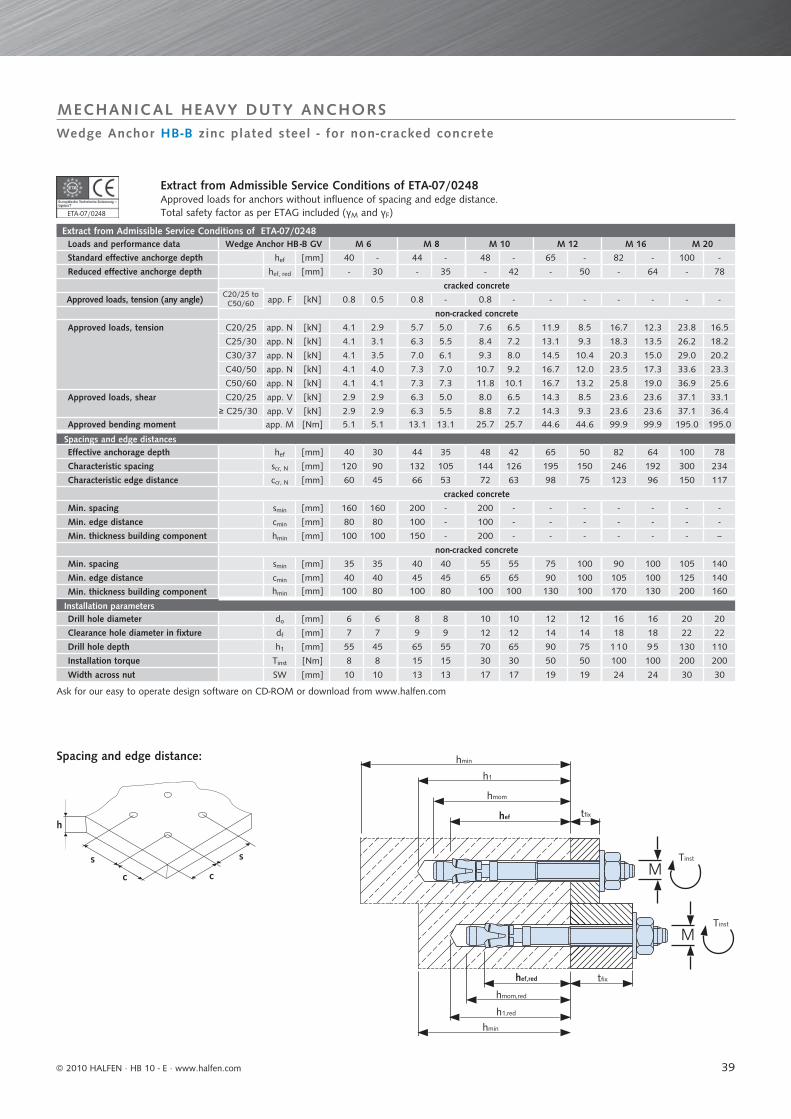
39
Extract from Admissible Service Conditions of ETA-07/0248Loads and performance data Wedge Anchor HB -B GV M 6 M 8 M 10 M 12 M 16 M 20
Standard effective anchorge depth hef [mm] 40 - 44 - 48 - 65 - 82 - 100 -
Reduced effective anchorge depth hef, red [mm] - 30 - 35 - 42 - 50 - 64 - 78
cracked concrete
Approved loads, tension (any angle) app. F [kN] 0.8 0.5 0.8 - 0.8 - - - - - - -
non-cracked concrete
Approved loads, tension C20/25 app. N [kN] 4.1 2.9 5.7 5.0 7.6 6.5 11.9 8.5 16.7 12.3 23.8 16.5
C25/30 app. N [kN] 4.1 3.1 6.3 5.5 8.4 7.2 13.1 9.3 18.3 13.5 26.2 18.2
C30/37 app. N [kN] 4.1 3.5 7.0 6.1 9.3 8.0 14.5 10.4 20.3 15.0 29.0 20.2
C40/50 app. N [kN] 4.1 4.0 7.3 7.0 10.7 9.2 16.7 12.0 23.5 17.3 33.6 23.3
C50/60 app. N [kN] 4.1 4.1 7.3 7.3 11.8 10.1 16.7 13.2 25.8 19.0 36.9 25.6
Approved loads, shear C20/25 app. V [kN] 2.9 2.9 6.3 5.0 8.0 6.5 14.3 8.5 23.6 23.6 37.1 33.1
≥ C25/30 app. V [kN] 2.9 2.9 6.3 5.5 8.8 7.2 14.3 9.3 23.6 23.6 37.1 36.4Approved bending moment app. M [Nm] 5.1 5.1 13.1 13.1 25.7 25.7 44.6 44.6 99.9 99.9 195.0 195.0
Spacings and edge distancesEffective anchorage depth hef [mm] 40 30 44 35 48 42 65 50 82 64 100 78
Characteristic spacing scr, N [mm] 120 90 132 105 144 126 195 150 246 192 300 234
Characteristic edge distance ccr, N [mm] 60 45 66 53 72 63 98 75 123 96 150 117
cracked concrete
Min. spacing smin [mm] 160 160 200 - 200 - - - - - - -
Min. edge distance cmin [mm] 80 80 100 - 100 - - - - - - -
Min. thickness building component hmin [mm] 100 100 150 - 200 - - - - - - --
non-cracked concrete
Min. spacing smin [mm] 35 35 40 40 55 55 75 100 90 100 105 140
Min. edge distance cmin [mm] 40 40 45 45 65 65 90 100 105 100 125 140
Min. thickness building component hmin [mm] 100 80 100 80 100 100 130 100 170 130 200 160
Installation parametersDrill hole diameter do [mm] 6 6 8 8 10 10 12 12 16 16 20 20
Clearance hole diameter in fixture df [mm] 7 7 9 9 12 12 14 14 18 18 22 22
Drill hole depth h1 [mm] 55 45 65 55 70 65 90 75 110 95 130 110
Installation torque Tinst [Nm] 8 8 15 15 30 30 50 50 100 100 200 200
Width across nut SW [mm] 10 10 13 13 17 17 19 19 24 24 30 30
s
cc
h
s
M
M
hmin
hef tfi x
Tinst
h1
hmom
Tinst
hef,red tfi x
hmom,red
h1,red
hmin
ETA-07/02487
Extract from Admissible Service Conditions of ETA-07/0248Approved loads for anchors without influence of spacing and edge distance.Total safety factor as per ETAG included (γM and γF)
Wedge Anchor HB-B zinc plated steel - for non-cracked concrete
MECHANICAL HEAVY DUTY ANCHORS
C20/25 toC50/60
Ask for our easy to operate design software on CD-ROM or download from www.halfen.com
Spacing and edge distance:
© 2010 HALFEN · HB 10 - E · www.halfen.com
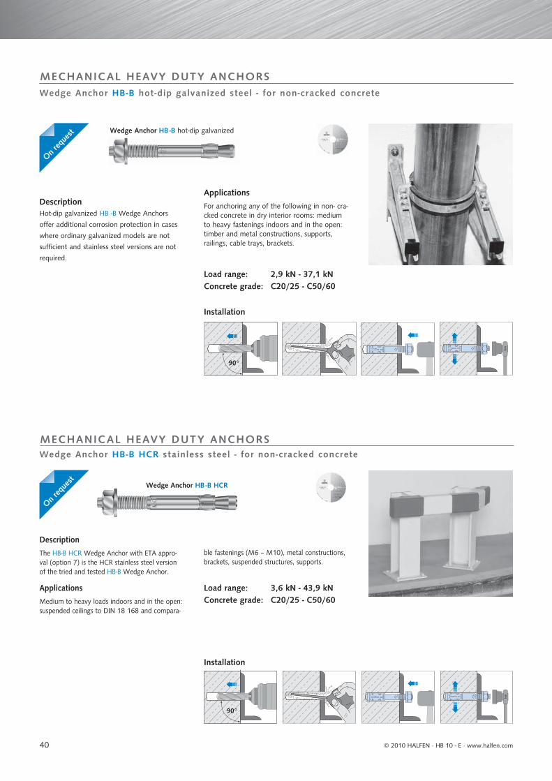
40
90°
Nm
90°
Nm
Wedge Anchor HB-B HCR stainless steel - for non-cracked concrete
MECHANICAL HEAVY DUTY ANCHORS
Wedge Anchor HB-B hot-dip galvanized steel - for non-cracked concrete
MECHANICAL HEAVY DUTY ANCHORS
DescriptionHot-dip galvanized HB -B Wedge Anchors
offer additional corrosion protection in cases
where ordinary galvanized models are not
sufficient and stainless steel versions are not
required.
Applications
For anchoring any of the following in non- cra-cked concrete in dry interior rooms: medium to heavy fastenings indoors and in the open: timber and metal constructions, supports, railings, cable trays, brackets.
Load range: 2,9 kN - 37,1 kNConcrete grade: C20/25 - C50/60
Wedge Anchor HB -B hot-dip galvanized
Description
The HB-B HCR Wedge Anchor with ETA appro-val (option 7) is the HCR stainless steel version of the tried and tested HB-B Wedge Anchor.
Applications
Medium to heavy loads indoors and in the open: suspended ceilings to DIN 18 168 and compara-
ble fastenings (M6 – M10), metal constructions, brackets, suspended structures, supports.
Load range: 3,6 kN - 43,9 kNConcrete grade: C20/25 - C50/60
Wedge Anchor HB -B HCR
Installation
Installation
On req
uest
On req
uest
© 2010 HALFEN · HB 10 - E ⋅ www.halfen.com

41
Wedge Anchor HB -B A4
Stainless steel A4
Approved for non-cracked concrete
Designation Article number
0432.060-
Drill holeØ
mm
Drill holedepth
mm
Setting depth
mm
Fixture thickness
tfix mm
An-chor
lengthmm
Thread
mm
Unit
piece
Weight per
pack.
kg
h1 h1,red hnom hnom,red tfi x tfi x,red
HB-B 6-5/40 A4 -00001 6 - 35 - 30 - 5 40 M6x16 100 1.12
HB-B 6-5-15/52 A4 -00133 6 - 45 - 38 - 5 52 M6x20 100 1.62
HB-B 6-10-20/67 A4 -00002 6 55 45 48 38 10 20 67 M6x20 100 2.07
HB-B 6-25-35/82 A4 -00003 6 55 45 48 38 25 35 82 M6x20 100 2.35HB-B 6-40-50/97 A4 -00004 6 55 45 48 38 40 50 97 M8x22 100 2.32
HB-B 8-5/50 A4 -00005 8 - 45 - 35 - 5 50 M8x25 100 2.74
HB-B 8-10/60 A4 -00023 8 - 50 - 40 - 10 60 M8x25 100 3.44
HB-B 8-10-19/75 A4 -00024 8 65 55 55 46 10 19 75 M8x25 100 3.55
HB-B 8-15-24/80 A4 -00006 8 65 55 55 46 15 24 80 M8x25 100 3.84
HB-B 8-20-29/85 A4 -00025 8 65 55 55 46 20 29 85 M8x25 100 4.00
HB-B 8-30-39/95 A4 -00007 8 65 55 55 46 30 39 95 M8x25 100 4.19
HB-B 8-45-54/110 A4 -00008 8 65 55 55 46 45 54 110 M8x25 100 4.78HB-B 8-55-64/120 A4 -00009 8 65 55 55 46 55 64 120 M8x25 100 5.09
HB-B 10-10/60 A4 -00026 10 - 50 - 40 - 10 60 M10x25 50 2.31HB-B 10-10-16/85 A4 -00027 10 70 65 60 54 10 16 85 M10x30 50 3.00
HB-B 10-15-21/90 A4 -00010 10 70 65 60 54 15 21 90 M10x30 50 3.06
HB-B 10-20-26/95 A4 -00028 10 70 65 60 54 20 26 95 M10x30 50 3.26
HB-B 10-30-36/105 A4 -00029 10 70 65 60 54 30 36 105 M10x30 50 3.47
HB-B 10-45-51/120 A4 -00011 10 70 65 60 54 45 51 120 M10x30 50 4.00
HB-B 10-50-56/125 A4 -00030 10 70 65 60 54 50 56 125 M10x30 50 4.21
HB-B 10-70-76/145 A4 -00031 10 70 65 60 54 70 76 145 M10x30 50 4.84
HB-B 10-100-106/175 A4 -00012 10 70 65 60 54 100 106 175 M10x30 50 5.70HB-B 10-140-146/215 A4 -00032 10 70 65 60 54 140 146 215 M10x30 25 3.79
HB-B 12-5/75 A4 -00033 12 - 65 - 55 - 5 75 M12x30 25 2.10HB-B 12-10/95 A4 -00034 12 - 80 - 70 - 10 95 M12x50 25 2.50
HB-B 12-10-25/105 A4 -00135 12 90 75 80 65 10 25 105 M12x35 25 2.62
HB-B 12-15-30/110 A4 -00013 12 90 75 80 65 15 30 110 M12x35 25 2.84
HB-B 12-20-35/115 A4 -00014 12 90 75 80 65 20 35 115 M12x35 25 3.11
HB-B 12-30-45/125 A4 -00015 12 90 75 80 65 30 45 125 M12x35 25 3.48
HB-B 12-50-65/145 A4 -00016 12 90 75 80 65 50 65 145 M12x35 25 3.82
HB-B 12-65-80/160 A4 -00035 12 90 75 80 65 65 80 160 M12x80 25 4.21
HB-B 12-85-100/180 A4 -00017 12 90 75 80 65 85 100 180 M12x80 25 4.64
HB-B 12-105-120/200 A4 -00036 12 90 75 80 65 105 120 200 M12x80 25 5.10
HB-B 12-125-140/220 A4 -00037 12 90 75 80 65 125 140 220 M12x80 20 4.48HB-B 12-145-160/240 A4 -00038 12 90 75 80 65 145 160 240 M12x80 20 4.75
HB-B 16-5/90 A4 -00136 16 - 75 - 65 - 5 90 M16x35 20 3.36
HB-B 16-15/115 A4 -00018 16 - 90 - 80 - 15 115 M16x40 20 4.14
HB-B 16-10-28-/130 A4 -00137 16 110 95 98 82 10 28 150 M16x40 20 5.04
HB-B 16-30-48/150 A4 -00019 16 110 95 98 82 30 48 180 M16x40 20 6.01
HB-B 16-60-78/180 A4 -00020 16 110 95 98 82 60 78 200 M16x80 10 3.45
HB-B 16-80-98/200 A4 -00021 16 110 95 98 82 80 98 220 M16x80 10 3.77
HB-B 16-100-118/220 A4 -00039 16 110 95 98 82 100 118 250 M16x80 10 4.25
HB-B 16-130-148/250 A4 -00040 16 110 95 98 82 130 148 285 M16x80 10 4.91HB-B 16-200-218/320 A4 -00138 16 110 95 98 82 200 218 320 M16x80 10 5.34
HB-B 20-5-27/150 A4 -00041 20 130 110 120 98 5 27 150 M20x45 10 4.06HB-B 20-35-57/180 A4 -00042 20 130 110 120 98 35 57 180 M20x45 10 4.96
HB-B 20-60-82/205 A4 -00022 20 130 110 120 98 60 82 205 M20x45 10 5.55
HB-B 20-95-117/240 A4 -00043 20 130 110 120 98 95 117 240 M20x45 10 6.50
Not part of approval. Reduced effective anchorage depth (observe reduced loads).
M 8 - M 10approved
M 10 - M 16
90°
Nm
ETA-07/02477
Fire testet
Wedge Anchor HB-B A4 - for non-cracked concrete
MECHANICAL HEAVY DUTY ANCHORS
Wedge Anchor HB-B A4
Description
The HB-B A4 Wedge Anchor with ETA approval (option 7) is the stainless steel version of the tried and tested HB-B Wedge Anchor.
Applications
Medium to heavy loads indoors and in the open: suspended ceilings as per DIN 18 168 and compa-rable fastenings (M6 - M10), metal constructions, brackets, suspended structures, supports.
Load range: 3,6 kN - 43,9 kNConcrete grade: C20/25 - C50/60
Installation
Preference anchor, HALFEN applications
=
© 2010 HALFEN · HB 10 - E · www.halfen.com
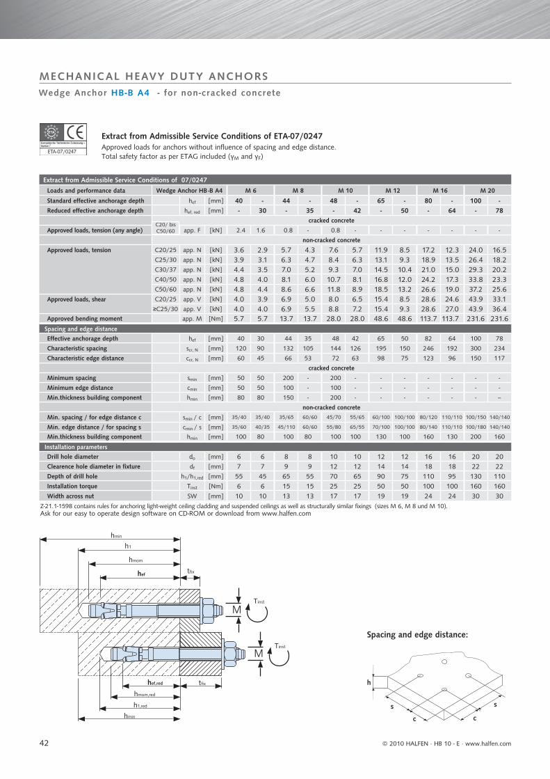
42
Extract from Admissible Service Conditions of 07/0247
Loads and performance data Wedge Anchor HB -B A4 M 6 M 8 M 10 M 12 M 16 M 20
Standard effective anchorage depth hef [mm] 40 - 44 - 48 - 65 - 80 - 100 -Reduced effective anchorage depth hef, red [mm] - 30 - 35 - 42 - 50 - 64 - 78
cracked concrete
Approved loads, tension (any angle) app. F [kN] 2.4 1.6 0.8 - 0.8 - - - - - - -
non-cracked concrete
Approved loads, tension C20/25 app. N [kN] 3.6 2.9 5.7 4.3 7.6 5.7 11.9 8.5 17.2 12.3 24.0 16.5C25/30 app. N [kN] 3.9 3.1 6.3 4.7 8.4 6.3 13.1 9.3 18.9 13.5 26.4 18.2C30/37 app. N [kN] 4.4 3.5 7.0 5.2 9.3 7.0 14.5 10.4 21.0 15.0 29.3 20.2C40/50 app. N [kN] 4.8 4.0 8.1 6.0 10.7 8.1 16.8 12.0 24.2 17.3 33.8 23.3C50/60 app. N [kN] 4.8 4.4 8.6 6.6 11.8 8.9 18.5 13.2 26.6 19.0 37.2 25.6
Approved loads, shear C20/25 app. V [kN] 4.0 3.9 6.9 5.0 8.0 6.5 15.4 8.5 28.6 24.6 43.9 33.1≥C25/30 app. V [kN] 4.0 4.0 6.9 5.5 8.8 7.2 15.4 9.3 28.6 27.0 43.9 36.4
Approved bending moment app. M [Nm] 5.7 5.7 13.7 13.7 28.0 28.0 48.6 48.6 113.7 113.7 231.6 231.6Spacing and edge distance
Effective anchorage depth hef [mm] 40 30 44 35 48 42 65 50 82 64 100 78
Characteristic spacing scr, N [mm] 120 90 132 105 144 126 195 150 246 192 300 234
Characteristic edge distance ccr, N [mm] 60 45 66 53 72 63 98 75 123 96 150 117
cracked concrete
Minimum spacing smin [mm] 50 50 200 - 200 - - - - - - -
Minimum edge distance cmin [mm] 50 50 100 - 100 - - - - - - -
Min.thickness building component hmin [mm] 80 80 150 - 200 - - - - - - --
non-cracked concrete
Min. spacing / for edge distance c smin / c [mm] 35/40 35/40 35/65 60/60 45/70 55/65 60/100 100/100 80/120 110/110 100/150 140/140
Min. edge distance / for spacing s cmin / s [mm] 35/60 40/35 45/110 60/60 55/80 65/55 70/100 100/100 80/140 110/110 100/180 140/140
Min.thickness building component hmin [mm] 100 80 100 80 100 100 130 100 160 130 200 160
Installation parameters
Drill hole diameter do [mm] 6 6 8 8 10 10 12 12 16 16 20 20Clearence hole diameter in fixture df [mm] 7 7 9 9 12 12 14 14 18 18 22 22Depth of drill hole h1/h1,red [mm] 55 45 65 55 70 65 90 75 110 95 130 110Installation torque Tinst [Nm] 6 6 15 15 25 25 50 50 100 100 160 160Width across nut SW [mm] 10 10 13 13 17 17 19 19 24 24 30 30
s
cc
h
s
M
M
hmin
hef tfi x
Tinst
h1
hmom
Tinst
hef,red tfi x
hmom,red
h1,red
hmin
ETA-07/02477
Wedge Anchor HB-B A4 - for non-cracked concrete
MECHANICAL HEAVY DUTY ANCHORS
Extract from Admissible Service Conditions of ETA-07/0247 Approved loads for anchors without influence of spacing and edge distance.Total safety factor as per ETAG included (γM and γF)
Z-21.1-1598 contains rules for anchoring light-weight ceiling cladding and suspended ceilings as well as structurally similar fixings (sizes M 6, M 8 und M 10).Ask for our easy to operate design software on CD-ROM or download from www.halfen.com
Spacing and edge distance:
C20/ bisC50/60
© 2010 HALFEN · HB 10 - E ⋅ www.halfen.com
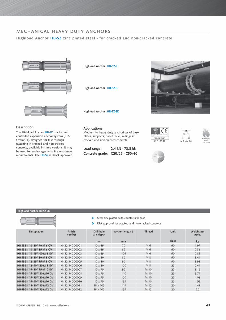
43
Highload Anchor HB-SZ-SK
Steel zinc plated, with countersunk head
ETA approval for cracked and non-cracked concrete
Designation Articlenumber
Drill holeØ x depth
mm
Anchor length L
mm
Thread Unit
piece
Weight per pack.
kgHB-SZ-SK 10- 10/ 70-M 6 GV 0432.340-00001 10 x 65 70 M 6 50 1.97HB-SZ-SK 10- 25/ 85-M 6 GV 0432.340-00002 10 x 65 85 M 6 50 2.36HB-SZ-SK 10- 45/100-M 6 GV 0432.340-00003 10 x 65 105 M 6 50 2.89HB-SZ-SK 12- 10/ 80-M 8 GV 0432.340-00004 12 x 80 80 M 8 50 3.41HB-SZ-SK 12- 25/ 95-M 8 GV 0432.340-00005 12 x 80 95 M 8 50 3.98HB-SZ-SK 12- 50/120-M 8 GV 0432.340-00006 12 x 80 120 M 8 25 2.41HB-SZ-SK 15- 10/ 95-M10 GV 0432.340-00007 15 x 95 95 M 10 25 3.16HB-SZ-SK 15- 25/110-M10 GV 0432.340-00008 15 x 95 110 M 10 25 3.71HB-SZ-SK 15- 35/120-M10 GV 0432.340-00009 15 x 95 120 M 10 25 4.08HB-SZ-SK 15- 50/135-M10 GV 0432.340-00010 15 x 95 135 M 10 25 4.53HB-SZ-SK 18- 20/115-M12 GV 0432.340-00011 18 x 105 115 M 12 20 4.49HB-SZ-SK 18- 40/135-M12 GV 0432.340-00012 18 x 105 135 M 12 20 5.2
M 8 - M 20M 6 - M 12ETA-09/04161
MECHANICAL HEAVY DUTY ANCHORSHighload Anchor HB-SZ zinc plated steel - for cracked and non-cracked concrete
Highload Anchor HB -SZ-S
DescriptionThe Highload Anchor HB-SZ is a torque controlled expansion anchor system (ETA, Option 1), designed for fast through fastening in cracked and non-cracked concrete, available in three versions. It may be used for anchorages with fi re resistance requirements. The HB-SZ is shock approved.
ApplicationsMedium to heavy duty anchorings of base plates, supports, pallet racks, railings in cracked and non-cracked concrete.
Load range: 2,4 kN - 73,8 kNConcrete grade: C20/25 - C50/60
Highload Anchor HB -SZ-B
Highload Anchor HB -SZ-SK
Fire tested
© 2010 HALFEN · HB 10 - E · www.halfen.com
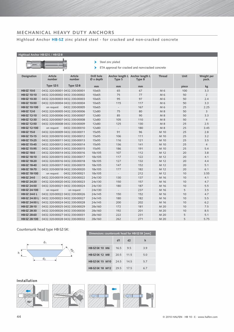
44
Highload Anchor HB-SZ-S / HB-SZ-B
Steel zinc plated
ETA approval for cracked and non-cracked concrete
Designation Articlenumber
Type SZ-S
Articlenumber
Type SZ-B
Drill holeØ x depth
mm
Anchor length LType S
mm
Anchor length LType B
mm
Thread Unit
piece
Weight per pack.
kgHB-SZ 10-0 0432.320-00001 0432.330-00001 10x65 65 67 M 6 100 3.3HB-SZ 10-10 0432.320-00002 0432.330-00002 10x65 75 77 M 6 50 2HB-SZ 10-30 0432.320-00003 0432.330-00003 10x65 95 97 M 6 50 2.4HB-SZ 10-50 0432.320-00004 0432.330-00004 10x65 115 117 M 6 50 3.3HB-SZ 10-100 on request 0432.330-00005 10x65 - 167 M 6 25 2.25HB-SZ 12-0 0432.320-00005 0432.330-00006 12x80 75 80 M 8 50 3HB-SZ 12-10 0432.320-00006 0432.330-00007 12x80 85 90 M 8 50 3.3HB-SZ 12-30 0432.320-00007 0432.330-00008 12x80 105 110 M 8 50 4HB-SZ 12-50 0432.320-00008 0432.330-00009 12x80 125 130 M 8 25 2.5HB-SZ 12-100 on request 0432.330-00010 12x80 - 180 M 8 25 3.45HB-SZ 15-0 0432.320-00009 0432.330-00011 15x95 91 96 M 10 25 2.8HB-SZ 15-15 0432.320-00010 0432.330-00012 15x95 106 111 M 10 25 3.2HB-SZ 15-25 0432.320-00011 0432.330-00013 15x95 116 121 M 10 25 3.5HB-SZ 15-45 0432.320-00012 0432.330-00014 15x95 136 141 M 10 25 4HB-SZ 15-95 0432.320-00013 0432.330-00015 15x95 186 191 M 10 25 5.4HB-SZ 18-0 0432.320-00014 0432.330-00016 18x105 107 112 M 12 20 3.8HB-SZ 18-10 0432.320-00015 0432.330-00017 18x105 117 122 M 12 20 4.1HB-SZ 18-20 0432.320-00016 0432.330-00018 18x105 127 132 M 12 20 4.4HB-SZ 18-40 0432.320-00017 0432.330-00019 18x105 147 152 M 12 20 5.1HB-SZ 18-70 0432.320-00018 0432.330-00020 18x105 177 182 M 12 20 6.1HB-SZ 18-100 on request 0432.330-00021 18x105 - 212 M 12 10 3.55HB-SZ 24-0 0432.320-00019 0432.330-00022 24x130 130 137 M 16 10 4.1HB-SZ 24-20 0432.320-00020 0432.330-00023 24x130 150 157 M 16 10 4.7HB-SZ 24-50 0432.320-00021 0432.330-00024 24x130 180 187 M 16 10 5.5HB-SZ 24-100 on request on request 24x130 - 237 M 16 5 3.5HB-SZ 24-0 L 0432.320-00022 0432.330-00026 24x145 150 152 M 16 10 4.7HB-SZ 24-30 L 0432.320-00023 0432.330-00027 24x145 180 182 M 16 10 5.5HB-SZ 24-50 L 0432.320-00024 0432.330-00028 24x145 200 202 M 16 10 6.2HB-SZ 28-10 0432.320-00025 0432.330-00029 28x160 172 181 M 20 10 7.5HB-SZ 28-30 0432.320-00026 0432.330-00030 28x160 192 201 M 20 10 8.5HB-SZ 28-60 0432.320-00027 0432.330-00031 28x160 222 231 M 20 5 5.1HB-SZ 28-100 0432.320-00028 0432.330-00032 28x160 262 271 M 20 5 5.75
Dimensions countersunk head for HB-SZ-SK [mm]
d1 d2 h
HB-SZ-SK 10 M6 16.5 9.5 3.9
HB-SZ-SK 12 M8 20.5 11.5 5.0
HB-SZ-SK 15 M10 24.5 14.5 5.7
HB-SZ-SK 18 M12 29.5 17.5 6.7
Nm
90°
d1
d2
h
45°
Highload Anchor HB-SZ zinc plated steel - for cracked and non-cracked concrete
Installation
Countersunk head type HB-SZ-SK:
MECHANICAL HEAVY DUTY ANCHORS
© 2010 HALFEN · HB 10 - E ⋅ www.halfen.com
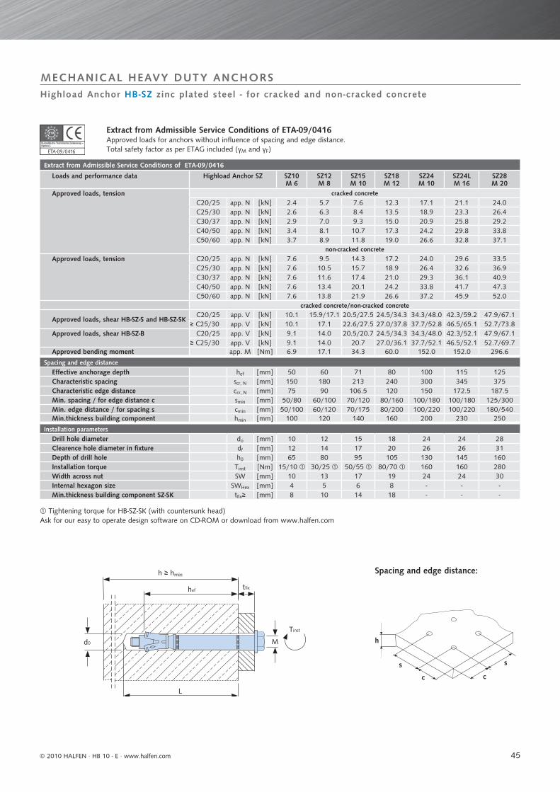
45
Tightening torque for HB-SZ-SK (with countersunk head)Ask for our easy to operate design software on CD-ROM or download from www.halfen.com
Extract from Admissible Service Conditions of ETA-09/0416
Loads and performance data Highload Anchor SZ SZ10M 6
SZ12M 8
SZ15M 10
SZ18M 12
SZ24M 10
SZ24LM 16
SZ28M 20
Approved loads, tension cracked concreteC20/25 app. N [kN] 2.4 5.7 7.6 12.3 17.1 21.1 24.0C25/30 app. N [kN] 2.6 6.3 8.4 13.5 18.9 23.3 26.4C30/37 app. N [kN] 2.9 7.0 9.3 15.0 20.9 25.8 29.2C40/50 app. N [kN] 3.4 8.1 10.7 17.3 24.2 29.8 33.8C50/60 app. N [kN] 3.7 8.9 11.8 19.0 26.6 32.8 37.1
non-cracked concreteApproved loads, tension C20/25 app. N [kN] 7.6 9.5 14.3 17.2 24.0 29.6 33.5
C25/30 app. N [kN] 7.6 10.5 15.7 18.9 26.4 32.6 36.9C30/37 app. N [kN] 7.6 11.6 17.4 21.0 29.3 36.1 40.9C40/50 app. N [kN] 7.6 13.4 20.1 24.2 33.8 41.7 47.3C50/60 app. N [kN] 7.6 13.8 21.9 26.6 37.2 45.9 52.0
cracked concrete/non-cracked concrete
Approved loads, shear HB-SZ-S and HB-SZ-SKC20/25 app. V [kN] 10.1 15.9/17.1 20.5/27.5 24.5/34.3 34.3/48.0 42.3/59.2 47.9/67.1
≥ C25/30 app. V [kN] 10.1 17.1 22.6/27.5 27.0/37.8 37.7/52.8 46.5/65.1 52.7/73.8Approved loads, shear HB-SZ-B C20/25 app. V [kN] 9.1 14.0 20.5/20.7 24.5/34.3 34.3/48.0 42.3/52.1 47.9/67.1
≥ C25/30 app. V [kN] 9.1 14.0 20.7 27.0/36.1 37.7/52.1 46.5/52.1 52.7/69.7Approved bending moment app. M [Nm] 6.9 17.1 34.3 60.0 152.0 152.0 296.6
Spacing and edge distance
Effective anchorage depth hef [mm] 50 60 71 80 100 115 125Characteristic spacing scr, N [mm] 150 180 213 240 300 345 375Characteristic edge distance ccr, N [mm] 75 90 106.5 120 150 172.5 187.5Min. spacing / for edge distance c smin [mm] 50/80 60/100 70/120 80/160 100/180 100/180 125/300Min. edge distance / for spacing s cmin [mm] 50/100 60/120 70/175 80/200 100/220 100/220 180/540Min.thickness building component hmin [mm] 100 120 140 160 200 230 250
Installation parameters
Drill hole diameter do [mm] 10 12 15 18 24 24 28Clearence hole diameter in fixture df [mm] 12 14 17 20 26 26 31Depth of drill hole h0 [mm] 65 80 95 105 130 145 160Installation torque Tinst [Nm] 15/10 30/25 50/55 80/70 160 160 280Width across nut SW [mm] 10 13 17 19 24 24 30Internal hexagon size SWHex [mm] 4 5 6 8 - - -Min.thickness building component SZ-SK tfix≥ [mm] 8 10 14 18 - - -
ETA-09/04161
h ≥ hmin
M
L
hef
Tinst
d0
tfi x
s
cc
h
s
Highload Anchor HB-SZ zinc plated steel - for cracked and non-cracked concrete
MECHANICAL HEAVY DUTY ANCHORS
Spacing and edge distance:
Extract from Admissible Service Conditions of ETA-09/0416 Approved loads for anchors without influence of spacing and edge distance.Total safety factor as per ETAG included (γM and γF)
© 2010 HALFEN · HB 10 - E · www.halfen.com
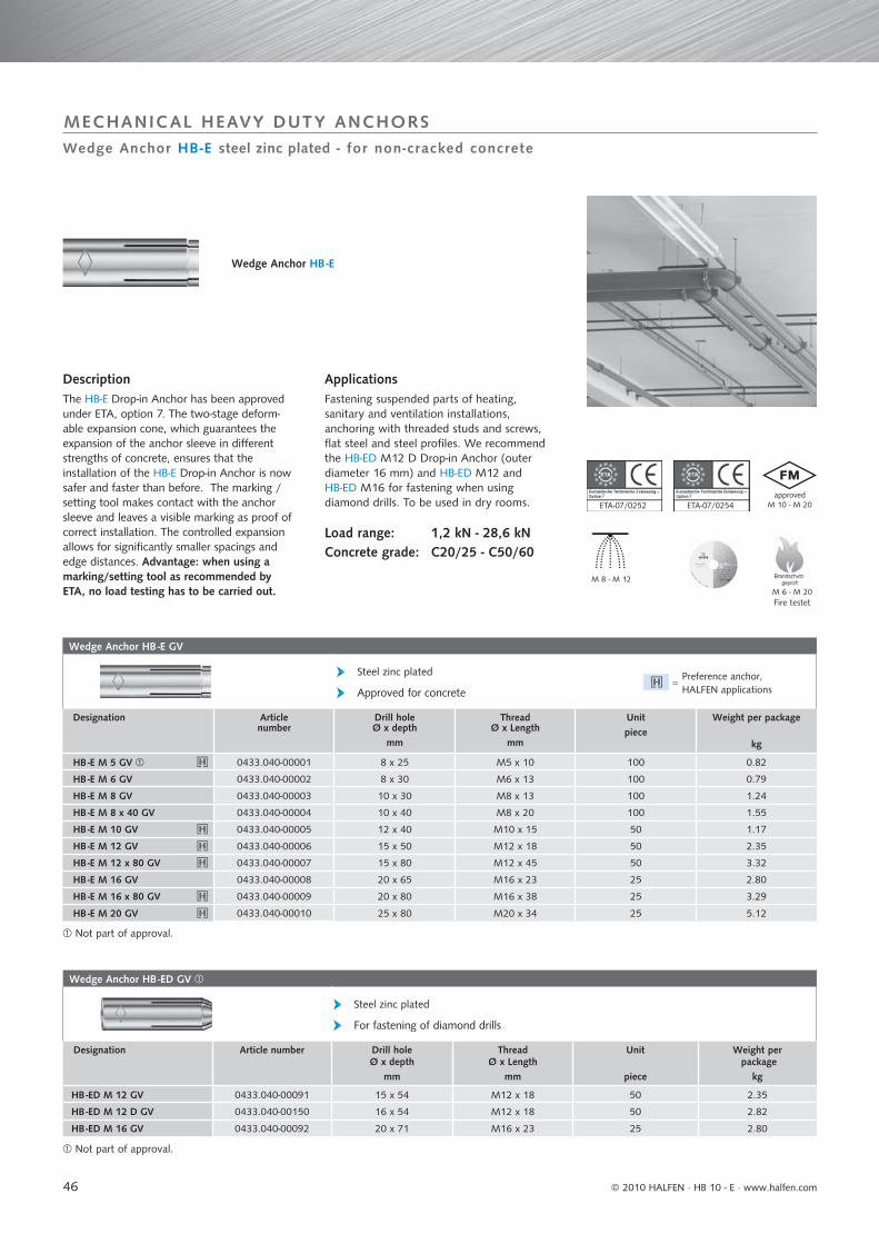
46
Wedge Anchor HB -E GV
Steel zinc plated
Approved for concrete
Designation Articlenumber
Drill holeØ x depth
mm
ThreadØ x Length
mm
Unitpiece
Weight per package
kg
HB -E M 5 GV 0433.040-00001 8 x 25 M5 x 10 100 0.82
HB -E M 6 GV 0433.040-00002 8 x 30 M6 x 13 100 0.79
HB -E M 8 GV 0433.040-00003 10 x 30 M8 x 13 100 1.24
HB -E M 8 x 40 GV 0433.040-00004 10 x 40 M8 x 20 100 1.55
HB -E M 10 GV 0433.040-00005 12 x 40 M10 x 15 50 1.17
HB -E M 12 GV 0433.040-00006 15 x 50 M12 x 18 50 2.35
HB -E M 12 x 80 GV 0433.040-00007 15 x 80 M12 x 45 50 3.32
HB -E M 16 GV 0433.040-00008 20 x 65 M16 x 23 25 2.80
HB -E M 16 x 80 GV 0433.040-00009 20 x 80 M16 x 38 25 3.29
HB -E M 20 GV 0433.040-00010 25 x 80 M20 x 34 25 5.12
Wedge Anchor HB -ED GV
Steel zinc plated
For fastening of diamond drills
Designation Article number Drill holeØ x depth
mm
ThreadØ x Length
mm
Unit
piece
Weight per package
kg
HB -ED M 12 GV 0433.040-00091 15 x 54 M12 x 18 50 2.35
HB -ED M 12 D GV 0433.040-00150 16 x 54 M12 x 18 50 2.82
HB -ED M 16 GV 0433.040-00092 20 x 71 M16 x 23 25 2.80
M 8 - M 12
approvedM 10 - M 20
M 6 - M 20
ETA-07/0252 ETA-07/02547 7
Wedge Anchor HB-E steel zinc plated - for non-cracked concrete
MECHANICAL HEAVY DUTY ANCHORS
DescriptionThe HB-E Drop-in Anchor has been approved under ETA, option 7. The two-stage deform-able expansion cone, which guarantees the expansion of the anchor sleeve in diff erent strengths of concrete, ensures that the installation of the HB-E Drop-in Anchor is now safer and faster than before. The marking /setting tool makes contact with the anchor sleeve and leaves a visible marking as proof of correct installation. The controlled expansion allows for signifi cantly smaller spacings and edge distances. Advantage: when using a marking/setting tool as recommended by ETA, no load testing has to be carried out.
Wedge Anchor HB -E
ApplicationsFastening suspended parts of heating, sanitary and ventilation installations, anchoring with threaded studs and screws, fl at steel and steel profi les. We recommend the HB-ED M12 D Drop-in Anchor (outer diameter 16 mm) and HB-ED M12 and HB-ED M16 for fastening when using diamond drills. To be used in dry rooms.
Load range: 1,2 kN - 28,6 kNConcrete grade: C20/25 - C50/60
Not part of approval.
Not part of approval.
Preference anchor, HALFEN applications
=
Fire testet
© 2010 HALFEN · HB 10 - E ⋅ www.halfen.com

47
Extract from Admissible Service Conditions of ETA-07/0252
Loads and performance data Drop-in Anchor HB -EM 5 M 6 M 8 M
8x40M 10 M 12 M
12x80M 16 M
16x80M 20
non-cracked concrete
Approved loads, tension (Screw 5.6 to 8.8) C20/25 app. N [kN] 1.4 3.3 2.8 3.6 5.1 7.1 7.1 10.5 10.5 14.3
C25/30 app. N [kN] 1.5 3.6 3.1 3.9 5.6 7.8 7.8 11.5 11.5 15.7
C30/37 app. N [kN] 1.7 3.6 3.4 4.1 6.2 8.6 8.6 12.8 12.8 17.5
C40/50 app. N [kN] 1.9 3.6 4.0 4.4 7.1 10.0 10.0 14.8 14.8 20.2
C50/60 app. N [kN] 2.1 3.6 4.4 4.6 7.8 11.0 11.0 16.2 16.2 22.2
Approved loads, shear (Screw 5.6) C20/25 app. V [kN] 1.5 2.1 3.9 3.9 4.1 9.0 9.0 16.8 16.8 26.2
Approved loads, shear (Screw 5.8 to 8.8) C20/25 app. V [kN] 2.0 2.9 3.9 3.9 4.1 12.0 12.0 18.0 18.0 28.6
Approved bending moment (Screw 5.6) app. M [Nm] - 2.7 8.1 8.1 15.8 27.8 27.8 71.0 71.0 138.6
Approved bending moment (Screw 5.8) app. M [Nm] - 3.7 10.9 10.9 21.1 37.1 37.1 94.9 94.9 185.1
Approved bending moment (Screw 8.8) app. M [Nm] - 5.8 17.1 17.1 34.3 60.0 60.0 152.0 152.0 296.6
Spacing and edge distance
Effective anchorage depth hef [mm] 25 30 30 40 40 50 80 65 80 80
Characteristic spacing scr, N [mm] 75 90 90 120 120 150 150 195 195 240
Characteristic edge distance ccr, N [mm] 37.5 45 45 60 60 75 75 97.5 97.5 120
Minimum spacing smin [mm] 60 55 60 80 100 120 120 150 150 160
Minimum edge distance cmin [mm] 95 95 95 95 135 165 165 200 200 260
Minimum thickness of building component hmin [mm] 100 100 100 100 120 130 130 160 160 200
Installation parameters
Drill hole diameter do [mm] 8 8 10 10 12 15 15 20 20 25
Clearance hole diameter in the fixture df [mm] 6 7 9 9 12 14 14 18 18 22
Drill hole depth h0 [mm] 25 30 30 40 40 50 80 65 80 80
Installation torque Tinst [Nm] 3 4 8 8 15 35 35 60 60 120
Standard setting tool HB-E-SW
Designation Article Nr
HB -E-SW 5 0433.040-00020
HB -E-SW 6 0433.040-00021
HB -E-SW 8 0433.040-00022
HB -E-SW 8 x 40 0433.040-00023
HB -E-SW 10 0433.040-00024
HB -E-SW 12 0433.040-00025
HB -E-SW 12 x 80 0433.040-00026
HB -E-SW 16 0433.040-00027
HB -E-SW 16 x 80 0433.040-00028
HB -E-SW 20 0433.040-00029
Marking/setting tool HB-E-MSW / HB-E-MSH
without hand guard with hand guard
Designation Articlenumber
Designation Articlenumber
HB -E-MSW 8 0433.040-00060 HB -E-MSH 8 0433.040-00170HB -E-MSW 8 x 40 0433.040-00061 HB -E-MSH 8 x 40 0433.040-00171HB -E-MSW 10 0433.040-00062 HB -E-MSH 10 0433.040-00172HB -E-MSW 12 0433.040-00063 HB -E-MSH 12 0433.040-00173HB -E-MSW 12 x 80 0433.040-00089 HB -E-MSH 12 x 80 0433.040-00174HB -E-MSW 16 0433.040-00064 HB -E-MSH 16 0433.040-00175HB -E-MSW 16 x 80 0433.040-00090 HB -E-MSH 16 x 80 0433.040-00176HB -E-MSW 20 0433.040-00065 HB -E-MSH 20 0433.040-00177
s
cc
h
s
ETA-07/02527
Drop-in anchor HB-E zinc plated steel - for non-cracked concrete
MECHANICAL HEAVY DUTY ANCHORS
Extract from Admissible Service Conditions of ETA-07/0252Approved loads for anchors without influence of spacing and edge distance.Total safety factor as per ETAG included (γM and γF)
Application only for structurally indeterminate systems. Size M 5 is not part of the approval.Ask for our easy to operate design software on CD-ROM or download from www.halfen.com
for Drop-in Anchor HB-E for Drop-in Anchors HB -E and HB -ED
Drop-in anchor HB -EDrill hole, made with new drill bit in concrete grade C20/25:→ no deformation of cone during installation
Drop-in anchor HB -EDrill hole, made with worn drill bit in high-strength concrete (e.g. C50/60): → cone deforms during installation
The HB-E -MSW marking/setting tool marks the an-chor sleeve as an indication of correct installation.
Spacing and edge distance:
© 2010 HALFEN · HB 10 - E · www.halfen.com
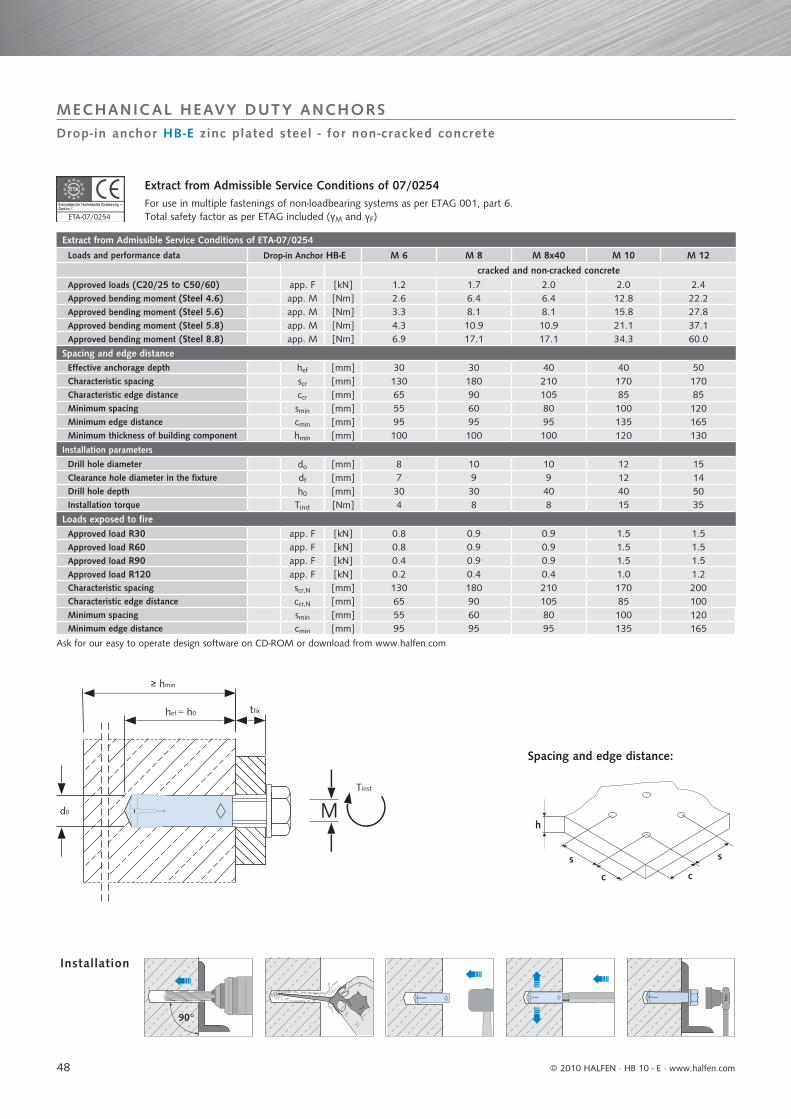
48
Extract from Admissible Service Conditions of 07/0254For use in multiple fastenings of non-loadbearing systems as per ETAG 001, part 6.Total safety factor as per ETAG included (γM and γF)
Extract from Admissible Service Conditions of ETA-07/0254
Loads and performance data Drop-in Anchor HB-E M 6 M 8 M 8x40 M 10 M 12
cracked and non-cracked concreteApproved loads (C20/25 to C50/60) app. F [kN] 1.2 1.7 2.0 2.0 2.4Approved bending moment (Steel 4.6) app. M [Nm] 2.6 6.4 6.4 12.8 22.2Approved bending moment (Steel 5.6) app. M [Nm] 3.3 8.1 8.1 15.8 27.8Approved bending moment (Steel 5.8) app. M [Nm] 4.3 10.9 10.9 21.1 37.1Approved bending moment (Steel 8.8) app. M [Nm] 6.9 17.1 17.1 34.3 60.0
Spacing and edge distanceEffective anchorage depth hef [mm] 30 30 40 40 50Characteristic spacing scr [mm] 130 180 210 170 170Characteristic edge distance ccr [mm] 65 90 105 85 85Minimum spacing smin [mm] 55 60 80 100 120Minimum edge distance cmin [mm] 95 95 95 135 165Minimum thickness of building component hmin [mm] 100 100 100 120 130
Installation parameters
Drill hole diameter do [mm] 8 10 10 12 15Clearance hole diameter in the fixture df [mm] 7 9 9 12 14Drill hole depth h0 [mm] 30 30 40 40 50Installation torque Tinst [Nm] 4 8 8 15 35
Loads exposed to fireApproved load R30 app. F [kN] 0.8 0.9 0.9 1.5 1.5Approved load R60 app. F [kN] 0.8 0.9 0.9 1.5 1.5Approved load R90 app. F [kN] 0.4 0.9 0.9 1.5 1.5Approved load R120 app. F [kN] 0.2 0.4 0.4 1.0 1.2Characteristic spacing scr,N [mm] 130 180 210 170 200Characteristic edge distance ccr,N [mm] 65 90 105 85 100Minimum spacing smin [mm] 55 60 80 100 120Minimum edge distance cmin [mm] 95 95 95 135 165
Ask for our easy to operate design software on CD-ROM or download from www.halfen.com
Nm
90°
ETA-07/0254
s
cc
h
s
M
≥ hmin
hef = h0
Tinst
d0
tfi x
7
MECHANICAL HEAVY DUTY ANCHORS
Installation
Drop-in anchor HB-E zinc plated steel - for non-cracked concrete
Spacing and edge distance:
© 2010 HALFEN · HB 10 - E ⋅ www.halfen.com
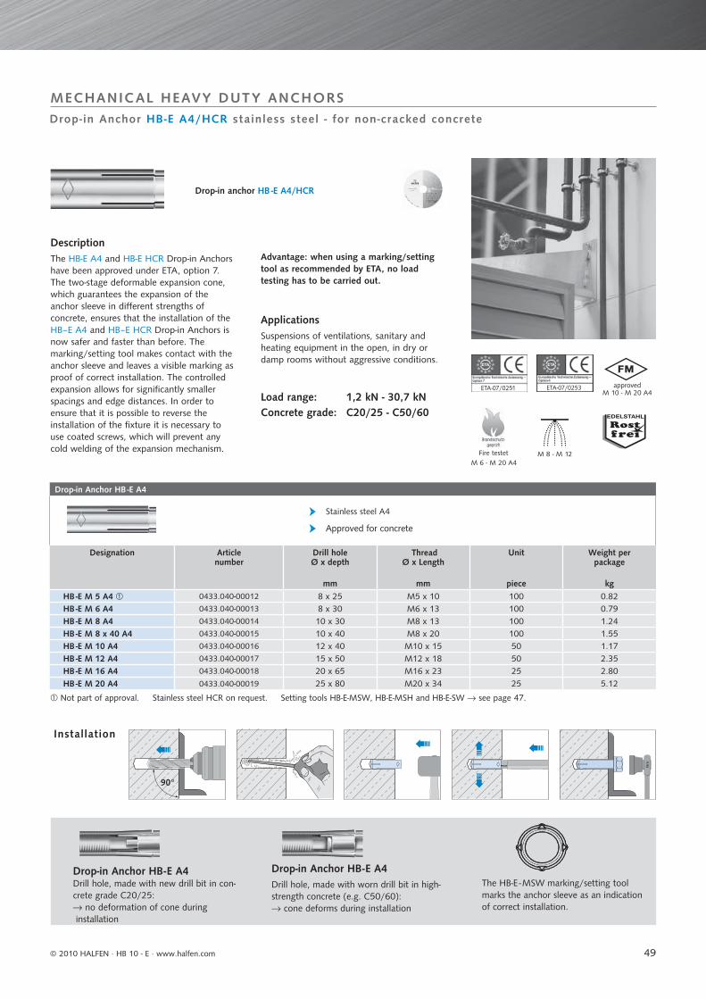
49
Drop-in Anchor HB -E A4
Stainless steel A4
Approved for concrete
Designation Articlenumber
Drill holeØ x depth
mm
ThreadØ x Length
mm
Unit
piece
Weight per package
kgHB -E M 5 A4 0433.040-00012 8 x 25 M5 x 10 100 0.82HB -E M 6 A4 0433.040-00013 8 x 30 M6 x 13 100 0.79HB -E M 8 A4 0433.040-00014 10 x 30 M8 x 13 100 1.24HB -E M 8 x 40 A4 0433.040-00015 10 x 40 M8 x 20 100 1.55HB -E M 10 A4 0433.040-00016 12 x 40 M10 x 15 50 1.17HB -E M 12 A4 0433.040-00017 15 x 50 M12 x 18 50 2.35HB -E M 16 A4 0433.040-00018 20 x 65 M16 x 23 25 2.80HB -E M 20 A4 0433.040-00019 25 x 80 M20 x 34 25 5.12
M 8 - M 12
approvedM 10 - M 20 A4
M 6 - M 20 A4
ETA-07/0251
Nm
90°
ETA-07/02537 4
Drop-in Anchor HB-E A4/HCR stainless steel - for non-cracked concrete
MECHANICAL HEAVY DUTY ANCHORS
DescriptionThe HB-E A4 and HB-E HCR Drop-in Anchors have been approved under ETA, option 7. The two-stage deformable expansion cone, which guarantees the expansion of the anchor sleeve in diff erent strengths of concrete, ensures that the installation of the HB–E A4 and HB–E HCR Drop-in Anchors is now safer and faster than before. The marking/setting tool makes contact with the anchor sleeve and leaves a visible marking as proof of correct installation. The controlled expansion allows for signifi cantly smaller spacings and edge distances. In order to ensure that it is possible to reverse the installation of the fi xture it is necessary to use coated screws, which will prevent any cold welding of the expansion mechanism.
Drop-in Anchor HB-E A4 Drill hole, made with new drill bit in con-crete grade C20/25:→ no deformation of cone during installation
Drop-in Anchor HB-E A4Drill hole, made with worn drill bit in high-strength concrete (e.g. C50/60):→ cone deforms during installation
The HB-E -MSW marking/setting tool marks the anchor sleeve as an indication of correct installation.
Advantage: when using a marking/setting tool as recommended by ETA, no load testing has to be carried out.
ApplicationsSuspensions of ventilations, sanitary and heating equipment in the open, in dry or damp rooms without aggressive conditions.
Load range: 1,2 kN - 30,7 kNConcrete grade: C20/25 - C50/60
Drop-in anchor HB -E A4/HCR
Not part of approval. Stainless steel HCR on request. Setting tools HB-E-MSW, HB-E-MSH and HB-E-SW → see page 47.
Installation
Fire testet
© 2010 HALFEN · HB 10 - E · www.halfen.com
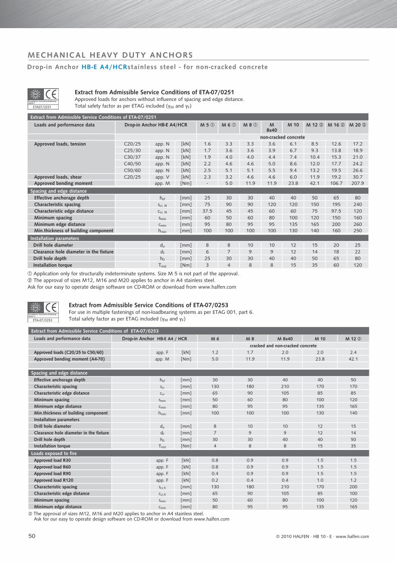
50
Extract from Admissible Service Conditions of ETA-07/0251
Loads and performance data Drop-in Anchor HB-E A4/HCR M 5 M 6 M 8 M8x40
M 10 M 12 M 16 M 20
non-cracked concreteApproved loads, tension C20/25 app. N [kN] 1.6 3.3 3.3 3.6 6.1 8.5 12.6 17.2
C25/30 app. N [kN] 1.7 3.6 3.6 3.9 6.7 9.3 13.8 18.9C30/37 app. N [kN] 1.9 4.0 4.0 4.4 7.4 10.4 15.3 21.0C40/50 app. N [kN] 2.2 4.6 4.6 5.0 8.6 12.0 17.7 24.2C50/60 app. N [kN] 2.5 5.1 5.1 5.5 9.4 13.2 19.5 26.6
Approved loads, shear C20/25 app. V [kN] 2.3 3.2 4.6 4.6 6.0 11.9 19.2 30.7Approved bending moment app. M [Nm] - 5.0 11.9 11.9 23.8 42.1 106.7 207.9
Spacing and edge distanceEffective anchorage depth hef [mm] 25 30 30 40 40 50 65 80Characteristic spacing scr, N [mm] 75 90 90 120 120 150 195 240Characteristic edge distance ccr, N [mm] 37.5 45 45 60 60 75 97.5 120Minimum spacing smin [mm] 60 50 60 80 100 120 150 160Minimum edge distance cmin [mm] 95 80 95 95 135 165 200 260Min.thickness of building component hmin [mm] 100 100 100 100 130 140 160 250
Installation parametersDrill hole diameter do [mm] 8 8 10 10 12 15 20 25Clearance hole diameter in the fixture df [mm] 6 7 9 9 12 14 18 22Drill hole depth h0 [mm] 25 30 30 40 40 50 65 80Installation torque Tinst [Nm] 3 4 8 8 15 35 60 120
Extract from Admissible Service Conditions of ETA-07/0253For use in multiple fastenings of non-loadbearing systems as per ETAG 001, part 6.Total safety factor as per ETAG included (γM and γF)
Extract from Admissible Service Conditions of ETA-07/0253Loads and performance data Drop-in Anchor HB-E A4 / HCR M 6 M 8 M 8x40 M 10 M 12
cracked and non-cracked concreteApproved loads (C20/25 to C50/60) app. F [kN] 1.2 1.7 2.0 2.0 2.4Approved bending moment (A4-70) app. M [Nm] 5.0 11.9 11.9 23.8 42.1
Spacing and edge distanceEffective anchorage depth hef [mm] 30 30 40 40 50Characteristic spacing scr [mm] 130 180 210 170 170Characteristic edge distance ccr [mm] 65 90 105 85 85Minimum spacing smin [mm] 50 60 80 100 120Minimum edge distance cmin [mm] 80 95 95 135 165Min.thickness of building component hmin [mm] 100 100 100 130 140Installation parametersDrill hole diameter do [mm] 8 10 10 12 15Clearance hole diameter in the fixture df [mm] 7 9 9 12 14Drill hole depth h0 [mm] 30 30 40 40 50Installation torque Tinst [Nm] 4 8 8 15 35
Loads exposed to fireApproved load R30 app. F [kN] 0.8 0.9 0.9 1.5 1.5Approved load R60 app. F [kN] 0.8 0.9 0.9 1.5 1.5Approved load R90 app. F [kN] 0.4 0.9 0.9 1.5 1.5Approved load R120 app. F [kN] 0.2 0.4 0.4 1.0 1.2Characteristic spacing scr,fi [mm] 130 180 210 170 200Characteristic edge distance ccr,fi [mm] 65 90 105 85 100Minimum spacing smin [mm] 50 60 80 100 120Minimum edge distance cmin [mm] 80 95 95 135 165
The approval of sizes M12, M16 and M20 applies to anchor in A4 stainless steel. Ask for our easy to operate design software on CD-ROM or download from www.halfen.com
ETA07/0251
ETA-07/02534
7
Drop-in Anchor HB-E A4/HCRstainless steel - for non-cracked concrete
MECHANICAL HEAVY DUTY ANCHORS
Extract from Admissible Service Conditions of ETA-07/0251Approved loads for anchors without influence of spacing and edge distance.Total safety factor as per ETAG included (γM and γF)
Application only for structurally indeterminate systems. Size M 5 is not part of the approval. The approval of sizes M12, M16 and M20 applies to anchor in A4 stainless steel.
Ask for our easy to operate design software on CD-ROM or download from www.halfen.com
© 2010 HALFEN · HB 10 - E · www.halfen.com
51
Tested for fire resistance
Tested for fire resistance
The Windows software for quick and easy structural calculations and sizing of anchor fastenings.
PC requirements:• Windows 2000 / XP / Vista / Windows 7• Screen resolution at least 600 x 800 pixel
Easy-to-use structural calculations for anchor fastenings
clear entry layout, printout self-explanatory
design using the CC procedure as per ETAG appendix C.
ServiceHALFEN ANCHOR BOLTS
Fire Resistance TablesHALFEN Anchors have the benefi t of fi re resistance testing → Pages 53 - 54.We are happy to send you the complete test reports on request.
We off er a comprehensive service to our customers. Talk to us
directly to obtain competent technical support for your projects. Or ask us about any details – we are happy to help.
Design aids Use these to quickly determine the load-bearing capacities of different standard anchor arrangements. → Pages 55 - 70
Support We also offer our support via tele-phone.Our Technical Competence-Center will advise you in questions of detail or work out complete projects for you. → You will fi nd our contact data on the last page of this catalogue.
DesignWe design and calculate fastening solutions for complete projects, for example for supporting brick or natu-ral stone claddings.
Ask for our design software or use our free-of-charge down-load service at www.halfen.com
Hal fen Des ign Sof tware
© 2010 HALFEN · HB 10 - E · www.halfen.com

52
Anchor Bolt system IBMB-test report Size Maximum tensile load [kN] in fire testsas per DIN 4102-2 for fire resistant classes
F 30(30 min)
F 60(60 min)
F 90(90 min)
F 120(120 min)
Injection System HB -VMZSteel, zinc plated / stainless steel A4 / stainless steel 1.4529
3191/5064
M 8 3.00 0.30 --- ---
M 10 7.00 0.95 0.30 ---
M 12 10.00 2.80 1.35 0.80
M 16 12.00 6.40 4.40 3.40
M 20 17.00 8.80 6.00 4.50
M 24 24.50 12.70 8.60 6.50
Injection System HB -VMUSteel, zinc plated / stainless steel A4 / stainless steel 1.4529
3440/5853
M 8 1.90 0.85 0.55 0.40
M 10 4.50 2.10 1.35 1.00
M 12 6.00 3.00 2.00 1.50
M 16 11.00 6.60 4.90 4.00
M 20 16.00 9.00 6.40 5.00
Wedge Anchor HB -BZSteel zinc plated
ETA-07/0250
M 8 1.30 1.10 0.80 0.70
M 10 2.20 1.80 1.40 1.20
M 12 3.00 2.80 2.40 2.20
M 16 6.00 5.20 4.40 4.00
M 20 9.00 8.20 6.90 6.30
M 24 11.00 11.00 10.00 8.80
Wedge Anchor HB -BZ A4Stainless steel A4
ETA-07/0249
M 8 1.30 1.10 0.80 0.70
M 10 2.20 1.80 1.40 1.20
M 12 3.00 2.80 2.40 2.20
M 16 6.00 5.20 4.40 4.00
M 20 9.00 8.20 6.90 6.30
Wedge Anchor HB -BZ HCRStainless steel 1.4529
M 8 1.30 1.10 0.80 0.70
M 10 2.20 1.80 1.40 1.20
M 12 3.00 2.80 2.40 2.20
M 16 6.00 5.20 4.40 4.00
M 20 9.00 8.20 6.90 6.30
Wedge Anchor HB -B, HB -B-U, HB -B-LSteel zinc plated
3174/1748-1
M 6 0.90 0.50 0.30 0.25
M 8 1.40 0.80 0.50 0.40
M 10 2.20 1.20 0.80 0.60
M 12 3.20 1.80 1.20 0.90
M 16 6.00 3.40 2.20 1.70
M 20 10.00 5.25 3.60 2.75
Wedge Anchor HB -B A4Stainless steel A4
3174/1748-1
M 6 0.90 0.50 0.30 0.25
M 8 2.30 1.70 1.40 1.30
M 10 3.60 2.60 2.20 2.00
M 12 5.20 3.80 3.20 2.90
M 16 9.70 7.00 6.00 5.40
M 20 15.00 10.20 8.20 7.00
Tested for fire resistance
Fire Resistant Anchor Systems
WEDGE ANCHORS
Tested in accordance with standardised tempe-rature curve (ISO 834, DIN EN 1363-1:1999-10, DIN 4102-2: 1977-09) in the cracked tension zone (concrete), exposed to open flames, without insulating or protecting coatings. The full test reports are available on request.
On req
uest
© 2010 HALFEN · HB 10 - E ⋅ www.halfen.com
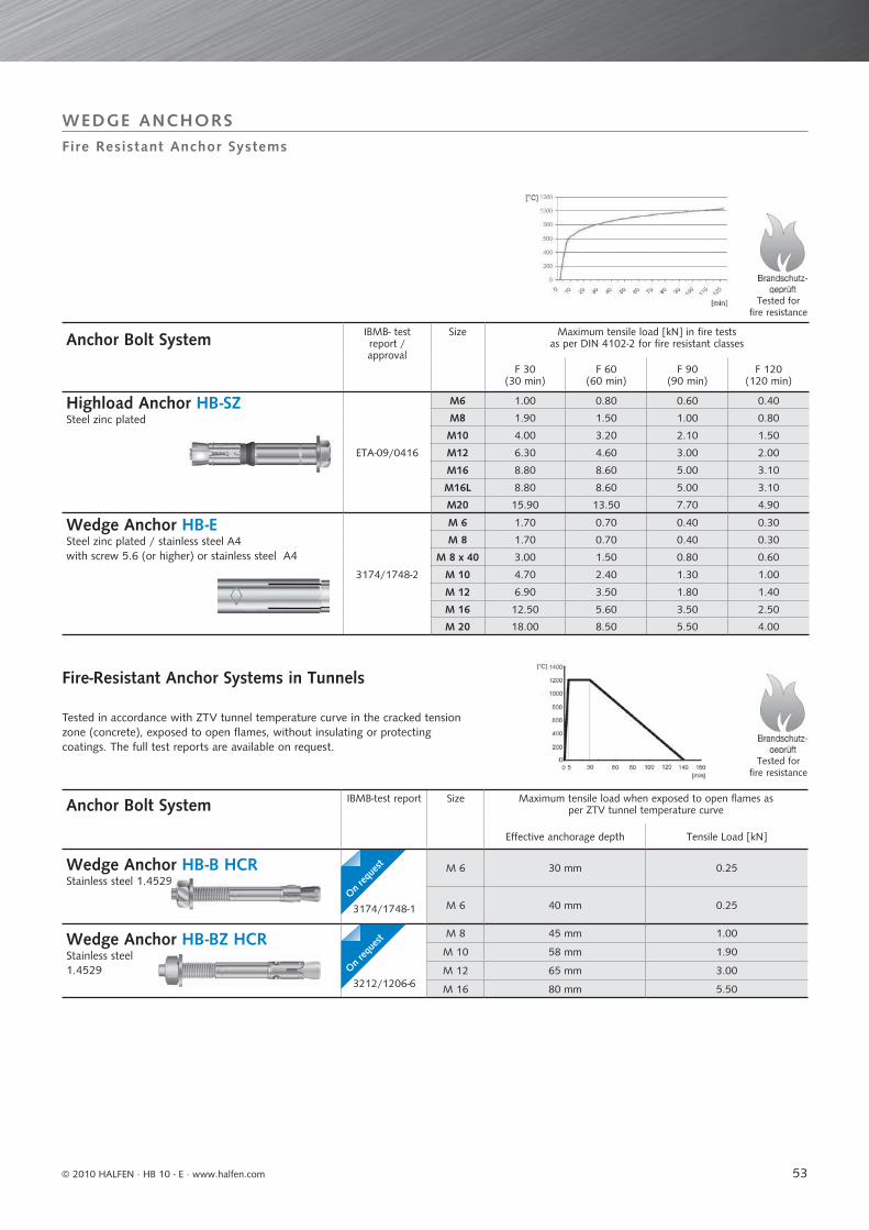
53
Anchor Bolt System IBMB- test report /approval
Size Maximum tensile load [kN] in fire testsas per DIN 4102-2 for fire resistant classes
F 30(30 min)
F 60(60 min)
F 90(90 min)
F 120(120 min)
Highload Anchor HB -SZSteel zinc plated
ETA-09/0416
M6 1.00 0.80 0.60 0.40
M8 1.90 1.50 1.00 0.80
M10 4.00 3.20 2.10 1.50
M12 6.30 4.60 3.00 2.00
M16 8.80 8.60 5.00 3.10
M16L 8.80 8.60 5.00 3.10
M20 15.90 13.50 7.70 4.90
Wedge Anchor HB -ESteel zinc plated / stainless steel A4with screw 5.6 (or higher) or stainless steel A4
3174/1748-2
M 6 1.70 0.70 0.40 0.30
M 8 1.70 0.70 0.40 0.30
M 8 x 40 3.00 1.50 0.80 0.60
M 10 4.70 2.40 1.30 1.00
M 12 6.90 3.50 1.80 1.40
M 16 12.50 5.60 3.50 2.50
M 20 18.00 8.50 5.50 4.00
Anchor Bolt System IBMB-test report Size Maximum tensile load when exposed to open flames as per ZTV tunnel temperature curve
Effective anchorage depth Tensile Load [kN]
Wedge Anchor HB -B HCRStainless steel 1.4529
3174/1748-1
M 6 30 mm 0.25
M 6 40 mm 0.25
Wedge Anchor HB -BZ HCRStainless steel1.4529
3212/1206-6
M 8 45 mm 1.00
M 10 58 mm 1.90
M 12 65 mm 3.00
M 16 80 mm 5.50
Tested for fire resistance
Tested for fire resistance
9
Fire Resistant Anchor Systems
WEDGE ANCHORS
Tested in accordance with ZTV tunnel temperature curve in the cracked tension zone (concrete), exposed to open fl ames, without insulating or protecting coatings. The full test reports are available on request.
Fire-Resistant Anchor Systems in Tunnels
On req
uest
On req
uest
© 2010 HALFEN · HB 10 - E · www.halfen.com
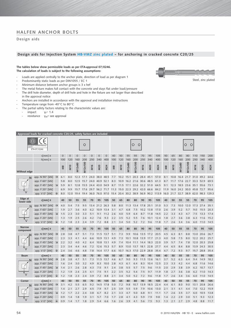
54
Approved loads for cracked concrete C20/25, safety factors are included
ETA-07/0246
s[mm] ≥ 0 0 0 0 0 0 0 40 50 55 55 70 95 105 50 65 80 80 110 150 200h[mm] ≥ 100 120 160 200 250 340 400 100 120 160 200 250 340 400 100 120 160 200 250 340 400
Without edge
M8
M10
M12
x80
M12
x100
M16
M20
M24
M8
M10
M12
x80
M12
x100
M16
M20
M24
M8
M10
M12
x80
M12
x100
M16
M20
M24
app. N 90° [kN] 6.1 8.0 12.3 17.1 24.0 38.0 48.5 7.7 10.2 15.1 20.3 28.4 45.1 57.0 8.1 10.8 16.4 21.7 31.0 49.2 64.6
app. F 60° [kN] 5.8 8.0 12.5 15.7 24.0 40.9 52.1 8.3 10.9 16.2 21.6 30.6 48.5 61.3 8.7 11.7 17.6 22.7 33.3 52.9 69.5
app. F 45° [kN] 5.9 8.1 12.8 15.5 24.4 43.0 54.9 8.7 11.5 17.1 22.6 32.2 51.0 64.5 9.1 12.3 18.5 23.6 35.1 55.6 73.1
app. F 20° [kN] 6.9 9.9 15.7 17.6 29.7 56.2 71.7 11.3 15.0 22.3 29.2 42.0 66.6 84.2 11.9 16.0 24.2 30.0 45.8 72.7 95.6
app. V 0° [kN] 8.0 12.0 19.4 19.4 36.0 76.0 97.0 15.4 20.4 30.2 38.9 56.9 90.2 113.9 16.0 21.7 32.7 38.9 62.0 98.3 129.3
Edge at lower side c[mm] ≥ 40 50 55 55 70 95 105 50 65 80 80 90 95 105 40 50 55 55 70 95 105
app. N 90° [kN] 4.0 5.4 7.5 9.5 13.4 21.2 26.3 5.8 8.0 11.3 13.4 17.8 25.1 31.0 5.3 7.3 10.0 12.0 17.3 27.4 35.1
app. F 60° [kN] 1.9 2.7 3.6 4.0 6.2 10.9 13.4 3.1 4.7 6.8 7.5 10.2 13.8 17.0 2.6 3.9 5.2 5.7 9.0 15.5 20.3
app. F 45° [kN] 1.5 2.3 3.0 3.3 5.1 9.1 11.2 2.6 4.0 5.9 6.4 8.7 11.8 14.5 2.2 3.3 4.3 4.7 7.5 13.3 17.4
app. F 20° [kN] 1.3 1.9 2.5 2.6 4.2 7.6 9.3 2.2 3.5 5.2 5.5 7.6 10.1 12.4 1.8 2.7 3.6 3.8 6.3 11.6 15.2
app. V 0° [kN] 1.2 1.8 2.3 2.4 3.9 7.2 8.8 2.1 3.4 5.0 5.2 7.2 9.6 11.8 1.7 2.6 3.4 3.6 6.0 11.0 14.5
Narrow component c[mm] ≥ 40 50 55 55 70 95 105 50 65 80 80 90 95 105 40 50 55 55 70 95 105
app. N 90° [kN] 2.8 3.8 4.7 5.1 7.3 11.5 13.7 5.1 7.3 9.9 10.6 13.5 17.2 20.5 4.5 6.3 8.1 8.8 13.0 20.6 26.7
app. F 60° [kN] 2.3 3.3 4.1 4.4 6.6 10.9 13.1 4.9 7.3 10.1 10.8 13.9 17.7 21.3 4.0 5.8 7.5 8.0 12.2 20.2 25.7
app. F 45° [kN] 2.2 3.2 4.0 4.2 6.4 10.8 13.1 4.9 7.4 10.4 11.1 14.4 18.3 22.0 3.9 5.7 7.4 7.8 12.0 20.3 25.8
app. F 20° [kN] 2.3 3.4 4.4 4.6 7.2 12.6 15.3 5.7 8.9 13.0 13.7 18.1 22.8 27.7 4.4 6.5 8.4 8.8 13.9 24.3 30.5
app. V 0° [kN] 2.4 3.6 4.6 4.8 7.8 14.4 17.7 6.6 10.7 16.3 17.0 22.9 28.8 35.4 4.7 7.2 9.3 9.7 15.7 28.8 35.4
Beam c[mm] ≥ 40 50 55 55 70 95 105 50 65 80 80 90 95 105 40 50 55 55 70 95 105app. N 90° [kN] 2.8 3.8 4.7 5.1 7.3 11.5 13.7 4.6 6.7 9.0 9.3 11.5 13.6 16.1 3.7 5.2 6.3 6.4 9.4 14.9 18.2
app. F 60° [kN] 1.6 2.4 3.0 3.2 4.9 8.3 10.0 2.8 4.3 6.1 6.4 8.3 10.4 12.5 2.3 3.3 4.2 4.4 6.8 11.6 14.6
app. F 45° [kN] 1.4 2.1 2.6 2.8 4.3 7.5 9.1 2.4 3.8 5.5 5.7 7.5 9.6 11.5 2.0 2.9 3.8 3.9 6.2 10.7 13.7
app. F 20° [kN] 1.2 1.9 2.4 2.5 4.1 7.5 9.1 2.2 3.5 5.2 5.4 7.5 9.7 11.9 1.8 2.7 3.6 3.8 6.2 11.0 14.3
app. V 0° [kN] 1.2 1.8 2.3 2.4 3.9 7.2 8.8 2.1 3.4 5.0 5.2 7.2 9.6 11.8 1.7 2.6 3.4 3.6 6.0 11.0 14.5
Corner c[mm] ≥ 40 50 55 55 70 95 105 50 65 80 80 90 95 105 40 50 55 55 70 95 105app. N 90° [kN] 3.1 4.2 5.5 6.5 9.2 14.5 17.8 5.0 7.2 9.8 10.7 13.9 18.5 22.4 4.4 6.1 8.0 9.0 13.1 20.8 26.6
app. F 60° [kN] 1.4 2.1 2.7 2.9 4.5 7.9 9.7 2.5 3.9 5.5 5.9 7.9 10.6 13.0 2.1 3.1 4.1 4.4 7.0 12.2 15.9
app. F 45° [kN] 1.2 1.7 2.2 2.4 3.8 6.7 8.2 2.1 3.3 4.7 5.0 6.8 9.1 11.1 1.7 2.6 3.5 3.7 6.0 10.5 13.8
app. F 20° [kN] 0.9 1.4 1.8 1.9 3.1 5.7 7.0 1.7 2.8 4.1 4.3 5.9 7.9 9.8 1.4 2.2 2.9 3.0 5.1 9.3 12.3
app. V 0° [kN] 0.9 1.4 1.7 1.8 2.9 5.4 6.6 1.6 2.6 3.9 4.1 5.6 7.5 9.3 1.3 2.1 2.7 2.9 4.8 8.8 11.7
Design aids
HALFEN ANCHOR BOLTS
The tables below show permissible loads as per ETA-approval 07/0246.The calculation of loads is subject to the following assumptions:
- Loads are applied centrally to the anchor plate, direction of load as per diagram 1- Predominantly static loads as per DIN1055 / EC 1- Minimum distance between anchor groups is 3 x hef- The metal fixture makes full contact with the concrete and stays flat under load/pressure- The drill hole diameter, depth of drill hole and hole in the fixture are not larger than described in the approval notice- Anchors are installed in accordance with the approval and installation instructions- Temperature range from -40°C to 80°C- The partial safety factors relating to the characteristic values are: - impact γF= 1.4 - resistance γM= see approval
Design aids for Injection System HB-VMZ zinc plated – for anchoring in cracked concrete C20/25
Steel, zinc plated
© 2010 HALFEN · HB 10 - E ⋅ www.halfen.com
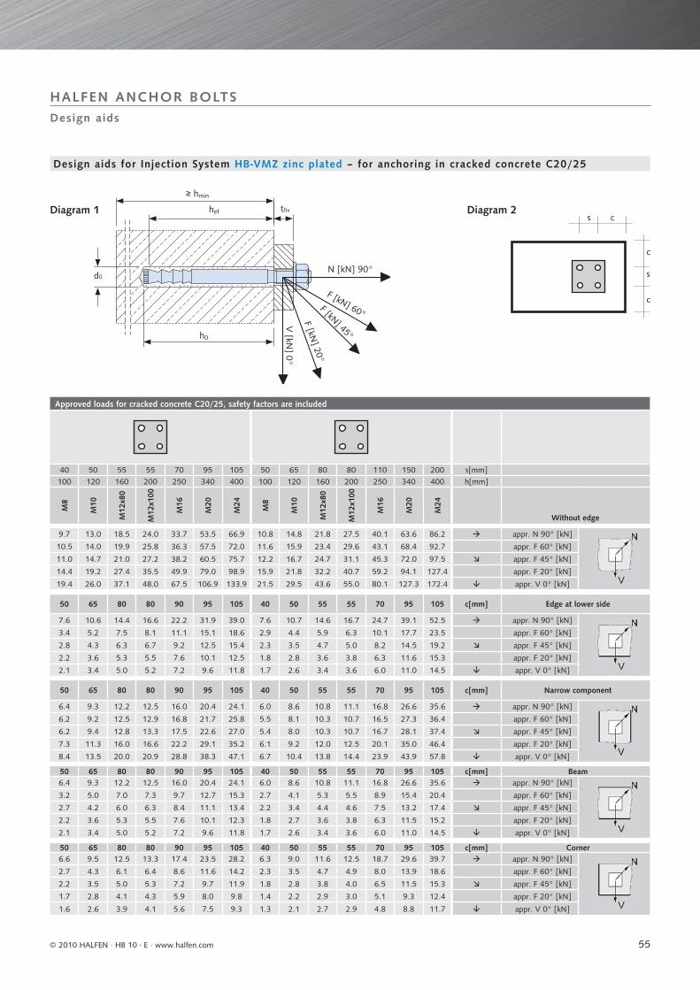
55
Approved loads for cracked concrete C20/25, safety factors are included
40 50 55 55 70 95 105 50 65 80 80 110 150 200 s[mm]100 120 160 200 250 340 400 100 120 160 200 250 340 400 h[mm]
M8
M10
M12
x80
M12
x100
M16
M20
M24
M8
M10
M12
x80
M12
x100
M16
M20
M24
Without edge
9.7 13.0 18.5 24.0 33.7 53.5 66.9 10.8 14.8 21.8 27.5 40.1 63.6 86.2 appr. N 90° [kN]
10.5 14.0 19.9 25.8 36.3 57.5 72.0 11.6 15.9 23.4 29.6 43.1 68.4 92.7 appr. F 60° [kN]
11.0 14.7 21.0 27.2 38.2 60.5 75.7 12.2 16.7 24.7 31.1 45.3 72.0 97.5 appr. F 45° [kN]
14.4 19.2 27.4 35.5 49.9 79.0 98.9 15.9 21.8 32.2 40.7 59.2 94.1 127.4 appr. F 20° [kN]
19.4 26.0 37.1 48.0 67.5 106.9 133.9 21.5 29.5 43.6 55.0 80.1 127.3 172.4 appr. V 0° [kN]
50 65 80 80 90 95 105 40 50 55 55 70 95 105 c[mm] Edge at lower side
7.6 10.6 14.4 16.6 22.2 31.9 39.0 7.6 10.7 14.6 16.7 24.7 39.1 52.5 appr. N 90° [kN]
3.4 5.2 7.5 8.1 11.1 15.1 18.6 2.9 4.4 5.9 6.3 10.1 17.7 23.5 appr. F 60° [kN]
2.8 4.3 6.3 6.7 9.2 12.5 15.4 2.3 3.5 4.7 5.0 8.2 14.5 19.2 appr. F 45° [kN]
2.2 3.6 5.3 5.5 7.6 10.1 12.5 1.8 2.8 3.6 3.8 6.3 11.6 15.3 appr. F 20° [kN]
2.1 3.4 5.0 5.2 7.2 9.6 11.8 1.7 2.6 3.4 3.6 6.0 11.0 14.5 appr. V 0° [kN]
50 65 80 80 90 95 105 40 50 55 55 70 95 105 c[mm] Narrow component
6.4 9.3 12.2 12.5 16.0 20.4 24.1 6.0 8.6 10.8 11.1 16.8 26.6 35.6 appr. N 90° [kN]
6.2 9.2 12.5 12.9 16.8 21.7 25.8 5.5 8.1 10.3 10.7 16.5 27.3 36.4 appr. F 60° [kN]
6.2 9.4 12.8 13.3 17.5 22.6 27.0 5.4 8.0 10.3 10.7 16.7 28.1 37.4 appr. F 45° [kN]
7.3 11.3 16.0 16.6 22.2 29.1 35.2 6.1 9.2 12.0 12.5 20.1 35.0 46.4 appr. F 20° [kN]
8.4 13.5 20.0 20.9 28.8 38.3 47.1 6.7 10.4 13.8 14.4 23.9 43.9 57.8 appr. V 0° [kN]
50 65 80 80 90 95 105 40 50 55 55 70 95 105 c[mm] Beam6.4 9.3 12.2 12.5 16.0 20.4 24.1 6.0 8.6 10.8 11.1 16.8 26.6 35.6 appr. N 90° [kN]
3.2 5.0 7.0 7.3 9.7 12.7 15.3 2.7 4.1 5.3 5.5 8.9 15.4 20.4 appr. F 60° [kN]
2.7 4.2 6.0 6.3 8.4 11.1 13.4 2.2 3.4 4.4 4.6 7.5 13.2 17.4 appr. F 45° [kN]
2.2 3.6 5.3 5.5 7.6 10.1 12.3 1.8 2.7 3.6 3.8 6.3 11.5 15.2 appr. F 20° [kN]
2.1 3.4 5.0 5.2 7.2 9.6 11.8 1.7 2.6 3.4 3.6 6.0 11.0 14.5 appr. V 0° [kN]
50 65 80 80 90 95 105 40 50 55 55 70 95 105 c[mm] Corner6.6 9.5 12.5 13.3 17.4 23.5 28.2 6.3 9.0 11.6 12.5 18.7 29.6 39.7 appr. N 90° [kN]
2.7 4.3 6.1 6.4 8.6 11.6 14.2 2.3 3.5 4.7 4.9 8.0 13.9 18.6 appr. F 60° [kN]
2.2 3.5 5.0 5.3 7.2 9.7 11.9 1.8 2.8 3.8 4.0 6.5 11.5 15.3 appr. F 45° [kN]
1.7 2.8 4.1 4.3 5.9 8.0 9.8 1.4 2.2 2.9 3.0 5.1 9.3 12.4 appr. F 20° [kN]
1.6 2.6 3.9 4.1 5.6 7.5 9.3 1.3 2.1 2.7 2.9 4.8 8.8 11.7 appr. V 0° [kN]
c
c
s
s c
d0
≥ hmin
hef tfix
N [kN] 90°
F [kN] 60°F [kN] 45°
F [kN] 20°
V [kN
] 0°
h0
Design aids
HALFEN ANCHOR BOLTS
Design aids for Injection System HB-VMZ zinc plated – for anchoring in cracked concrete C20/25
Diagram 1 Diagram 2
© 2010 HALFEN · HB 10 - E · www.halfen.com
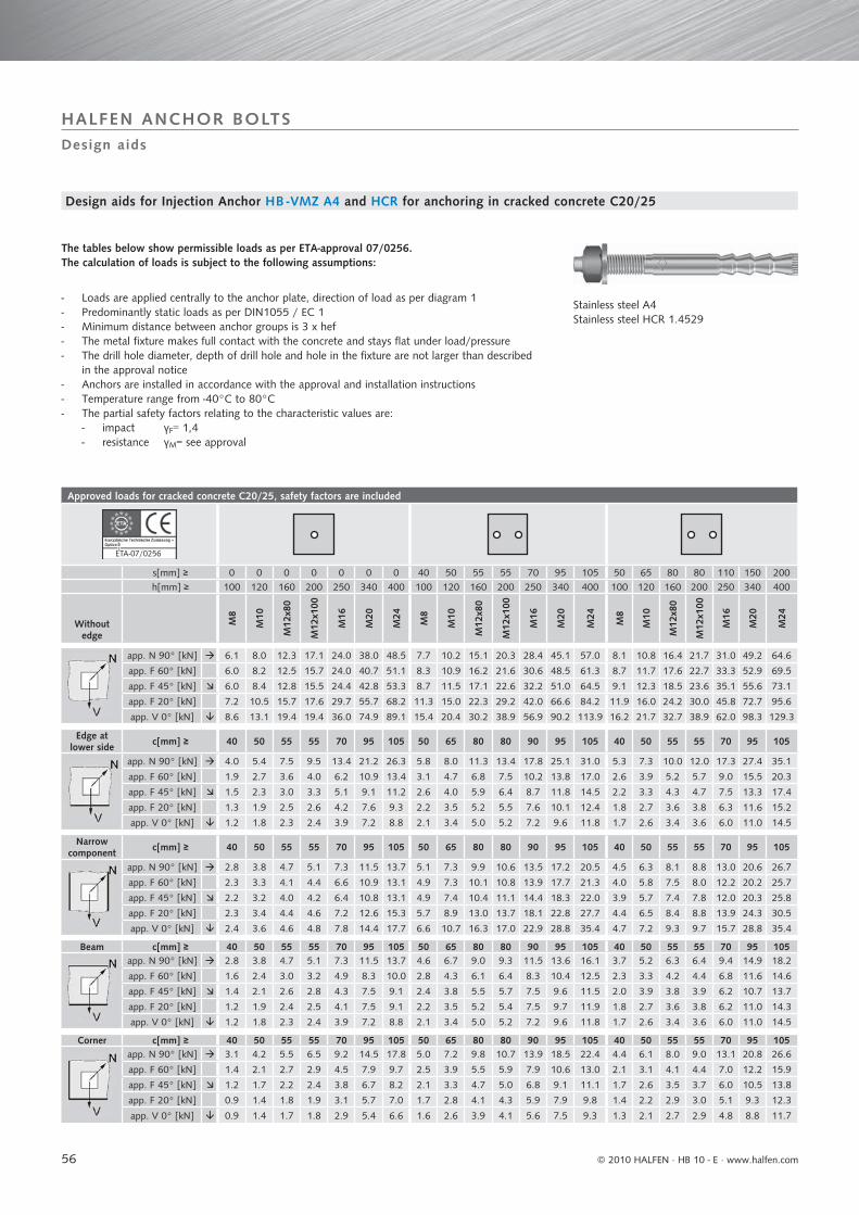
56
Approved loads for cracked concrete C20/25, safety factors are included
ETA-07/0256
s[mm] ≥ 0 0 0 0 0 0 0 40 50 55 55 70 95 105 50 65 80 80 110 150 200h[mm] ≥ 100 120 160 200 250 340 400 100 120 160 200 250 340 400 100 120 160 200 250 340 400
Without edge
M8
M10
M12
x80
M12
x100
M16
M20
M24
M8
M10
M12
x80
M12
x100
M16
M20
M24
M8
M10
M12
x80
M12
x100
M16
M20
M24
app. N 90° [kN] 6.1 8.0 12.3 17.1 24.0 38.0 48.5 7.7 10.2 15.1 20.3 28.4 45.1 57.0 8.1 10.8 16.4 21.7 31.0 49.2 64.6
app. F 60° [kN] 6.0 8.2 12.5 15.7 24.0 40.7 51.1 8.3 10.9 16.2 21.6 30.6 48.5 61.3 8.7 11.7 17.6 22.7 33.3 52.9 69.5
app. F 45° [kN] 6.0 8.4 12.8 15.5 24.4 42.8 53.3 8.7 11.5 17.1 22.6 32.2 51.0 64.5 9.1 12.3 18.5 23.6 35.1 55.6 73.1
app. F 20° [kN] 7.2 10.5 15.7 17.6 29.7 55.7 68.2 11.3 15.0 22.3 29.2 42.0 66.6 84.2 11.9 16.0 24.2 30.0 45.8 72.7 95.6
app. V 0° [kN] 8.6 13.1 19.4 19.4 36.0 74.9 89.1 15.4 20.4 30.2 38.9 56.9 90.2 113.9 16.2 21.7 32.7 38.9 62.0 98.3 129.3
Edge at lower side c[mm] ≥ 40 50 55 55 70 95 105 50 65 80 80 90 95 105 40 50 55 55 70 95 105
app. N 90° [kN] 4.0 5.4 7.5 9.5 13.4 21.2 26.3 5.8 8.0 11.3 13.4 17.8 25.1 31.0 5.3 7.3 10.0 12.0 17.3 27.4 35.1
app. F 60° [kN] 1.9 2.7 3.6 4.0 6.2 10.9 13.4 3.1 4.7 6.8 7.5 10.2 13.8 17.0 2.6 3.9 5.2 5.7 9.0 15.5 20.3
app. F 45° [kN] 1.5 2.3 3.0 3.3 5.1 9.1 11.2 2.6 4.0 5.9 6.4 8.7 11.8 14.5 2.2 3.3 4.3 4.7 7.5 13.3 17.4
app. F 20° [kN] 1.3 1.9 2.5 2.6 4.2 7.6 9.3 2.2 3.5 5.2 5.5 7.6 10.1 12.4 1.8 2.7 3.6 3.8 6.3 11.6 15.2
app. V 0° [kN] 1.2 1.8 2.3 2.4 3.9 7.2 8.8 2.1 3.4 5.0 5.2 7.2 9.6 11.8 1.7 2.6 3.4 3.6 6.0 11.0 14.5
Narrow component c[mm] ≥ 40 50 55 55 70 95 105 50 65 80 80 90 95 105 40 50 55 55 70 95 105
app. N 90° [kN] 2.8 3.8 4.7 5.1 7.3 11.5 13.7 5.1 7.3 9.9 10.6 13.5 17.2 20.5 4.5 6.3 8.1 8.8 13.0 20.6 26.7
app. F 60° [kN] 2.3 3.3 4.1 4.4 6.6 10.9 13.1 4.9 7.3 10.1 10.8 13.9 17.7 21.3 4.0 5.8 7.5 8.0 12.2 20.2 25.7
app. F 45° [kN] 2.2 3.2 4.0 4.2 6.4 10.8 13.1 4.9 7.4 10.4 11.1 14.4 18.3 22.0 3.9 5.7 7.4 7.8 12.0 20.3 25.8
app. F 20° [kN] 2.3 3.4 4.4 4.6 7.2 12.6 15.3 5.7 8.9 13.0 13.7 18.1 22.8 27.7 4.4 6.5 8.4 8.8 13.9 24.3 30.5
app. V 0° [kN] 2.4 3.6 4.6 4.8 7.8 14.4 17.7 6.6 10.7 16.3 17.0 22.9 28.8 35.4 4.7 7.2 9.3 9.7 15.7 28.8 35.4
Beam c[mm] ≥ 40 50 55 55 70 95 105 50 65 80 80 90 95 105 40 50 55 55 70 95 105app. N 90° [kN] 2.8 3.8 4.7 5.1 7.3 11.5 13.7 4.6 6.7 9.0 9.3 11.5 13.6 16.1 3.7 5.2 6.3 6.4 9.4 14.9 18.2
app. F 60° [kN] 1.6 2.4 3.0 3.2 4.9 8.3 10.0 2.8 4.3 6.1 6.4 8.3 10.4 12.5 2.3 3.3 4.2 4.4 6.8 11.6 14.6
app. F 45° [kN] 1.4 2.1 2.6 2.8 4.3 7.5 9.1 2.4 3.8 5.5 5.7 7.5 9.6 11.5 2.0 3.9 3.8 3.9 6.2 10.7 13.7
app. F 20° [kN] 1.2 1.9 2.4 2.5 4.1 7.5 9.1 2.2 3.5 5.2 5.4 7.5 9.7 11.9 1.8 2.7 3.6 3.8 6.2 11.0 14.3
app. V 0° [kN] 1.2 1.8 2.3 2.4 3.9 7.2 8.8 2.1 3.4 5.0 5.2 7.2 9.6 11.8 1.7 2.6 3.4 3.6 6.0 11.0 14.5
Corner c[mm] ≥ 40 50 55 55 70 95 105 50 65 80 80 90 95 105 40 50 55 55 70 95 105app. N 90° [kN] 3.1 4.2 5.5 6.5 9.2 14.5 17.8 5.0 7.2 9.8 10.7 13.9 18.5 22.4 4.4 6.1 8.0 9.0 13.1 20.8 26.6
app. F 60° [kN] 1.4 2.1 2.7 2.9 4.5 7.9 9.7 2.5 3.9 5.5 5.9 7.9 10.6 13.0 2.1 3.1 4.1 4.4 7.0 12.2 15.9
app. F 45° [kN] 1.2 1.7 2.2 2.4 3.8 6.7 8.2 2.1 3.3 4.7 5.0 6.8 9.1 11.1 1.7 2.6 3.5 3.7 6.0 10.5 13.8
app. F 20° [kN] 0.9 1.4 1.8 1.9 3.1 5.7 7.0 1.7 2.8 4.1 4.3 5.9 7.9 9.8 1.4 2.2 2.9 3.0 5.1 9.3 12.3
app. V 0° [kN] 0.9 1.4 1.7 1.8 2.9 5.4 6.6 1.6 2.6 3.9 4.1 5.6 7.5 9.3 1.3 2.1 2.7 2.9 4.8 8.8 11.7
1
Design aids
HALFEN ANCHOR BOLTS
The tables below show permissible loads as per ETA-approval 07/0256. The calculation of loads is subject to the following assumptions:
- Loads are applied centrally to the anchor plate, direction of load as per diagram 1- Predominantly static loads as per DIN1055 / EC 1- Minimum distance between anchor groups is 3 x hef- The metal fixture makes full contact with the concrete and stays flat under load/pressure- The drill hole diameter, depth of drill hole and hole in the fixture are not larger than described in the approval notice- Anchors are installed in accordance with the approval and installation instructions- Temperature range from -40°C to 80°C- The partial safety factors relating to the characteristic values are: - impact γF= 1,4 - resistance γM= see approval
Stainless steel A4Stainless steel HCR 1.4529
Design aids for Injection Anchor HB -VMZ A4 and HCR for anchoring in cracked concrete C20/25
© 2010 HALFEN · HB 10 - E ⋅ www.halfen.com

57
Approved loads for cracked concrete C20/25, safety factors are included
40 50 55 55 70 95 105 50 65 80 80 110 150 200 s[mm]100 120 160 200 250 340 400 100 120 160 200 250 340 400 h[mm]
M8
M10
M12
x80
M12
x100
M16
M20
M24
M8
M10
M12
x80
M12
x100
M16
M20
M24
Without edge
9.7 13.0 18.5 24.0 33.7 53.5 66.9 10.8 14.8 21.8 27.5 40.1 63.6 86.2 app. N 90° [kN] 10.5 14.0 19.9 25.8 36.3 57.5 72.0 11.6 15.9 23.4 29.6 43.1 68.4 92.7 app. F 60° [kN]11.0 14.7 21.0 27.2 38.2 60.5 75.7 12.2 16.7 24.7 31.1 45.3 72.0 97.5 app. F 45° [kN]14.4 19.2 27.4 35.5 49.9 79.0 98.9 15.9 21.8 32.2 40.7 59.2 94.1 127.4 app. F 20° [kN]19.4 26.0 37.1 48.0 67.5 106.9 133.9 21.5 29.5 43.6 55.0 80.1 127.3 172.4 app. V 0° [kN]
50 65 80 80 90 95 105 40 50 55 55 70 95 105 c[mm] Edge at lower side
7.6 10.6 14.4 16.6 22.2 31.9 39.0 7.6 10.7 14.6 16.7 24.7 39.1 52.5 app. N 90° [kN]3.4 5.2 7.5 8.1 11.1 15.1 18.6 2.9 4.4 5.9 6.3 10.1 17.7 23.5 app. F 60° [kN]2.8 4.3 6.3 6.7 9.2 12.5 15.4 2.3 3.5 4.7 5.0 8.2 14.5 19.2 app. F 45° [kN]2.2 3.6 5.3 5.5 7.6 10.1 12.5 1.8 2.8 3.6 3.8 6.3 11.6 15.3 app. F 20° [kN]2.1 3.4 5.0 5.2 7.2 9.6 11.8 1.7 2.6 3.4 3.6 6.0 11.0 14.5 app. V 0° [kN]
50 65 80 80 90 95 105 40 50 55 55 70 95 105 c[mm] Narrow component
6.4 9.3 12.2 12.5 16.0 20.4 24.1 6.0 8.6 10.8 11.1 16.8 26.6 35.6 app. N 90° [kN]6.2 9.2 12.5 12.9 16.8 21.7 25.8 5.5 8.1 10.3 10.7 16.5 27.3 36.4 app. F 60° [kN]6.2 9.4 12.8 13.3 17.5 22.6 27.0 5.4 8.0 10.3 10.7 16.7 28.1 37.4 app. F 45° [kN]7.3 11.3 16.0 16.6 22.2 29.1 35.2 6.1 9.2 12.0 12.5 20.1 35.0 46.4 app. F 20° [kN]8.4 13.5 20.0 20.9 28.8 38.3 47.1 6.7 10.4 13.8 14.4 23.9 43.9 57.8 app. V 0° [kN]
50 65 80 80 90 95 105 40 50 55 55 70 95 105 c[mm] Beam6.4 9.3 12.2 12.5 16.0 20.4 24.1 6.0 8.6 10.8 11.1 16.8 26.6 35.6 app. N 90° [kN]3.2 5.0 7.0 7.3 9.7 12.7 15.3 2.7 4.1 5.3 5.5 8.9 15.4 20.4 app. F 60° [kN]2.7 4.2 6.0 6.3 8.4 11.1 13.4 2.2 3.4 4.4 4.6 7.5 13.2 17.4 app. F 45° [kN]2.2 3.6 5.3 5.5 7.6 10.1 12.3 1.8 2.7 3.6 3.8 6.3 11.5 15.2 app. F 20° [kN]2.1 3.4 5.0 5.2 7.2 9.6 11.8 1.7 2.6 3.4 3.6 6.0 11.0 14.5 app. V 0° [kN]
50 65 80 80 90 95 105 40 50 55 55 70 95 105 c[mm] Corner6.6 9.5 12.5 13.3 17.4 23.5 28.2 6.3 9.0 11.6 12.5 18.7 29.6 39.7 app. N 90° [kN]2.7 4.3 6.1 6.4 8.6 11.6 14.2 2.3 3.5 4.7 4.9 8.0 13.9 18.6 app. F 60° [kN]2.2 3.5 5.0 5.3 7.2 9.7 11.9 1.8 2.8 3.8 4.0 6.5 11.5 15.3 app. F 45° [kN]1.7 2.8 4.1 4.3 5.9 8.0 9.8 1.4 2.2 2.9 3.0 5.1 9.3 12.4 app. F 20° [kN]1.6 2.6 3.9 4.1 5.6 7.5 9.3 1.3 2.1 2.7 2.9 4.8 8.8 11.7 app. V 0° [kN]
c
c
s
s chef
d0
tfix
N [kN] 90°
F [kN] 60°F [kN] 45°
F [kN] 20°
V [kN
] 0°
h0
≥ hmin
Design aids
HALFEN ANCHOR BOLTS
Diagram 2
Design aids for Injection Anchor HB -VMZ A4 and HCR for anchoring in cracked concrete C20/25
Diagram 1
© 2010 HALFEN · HB 10 - E · www.halfen.com
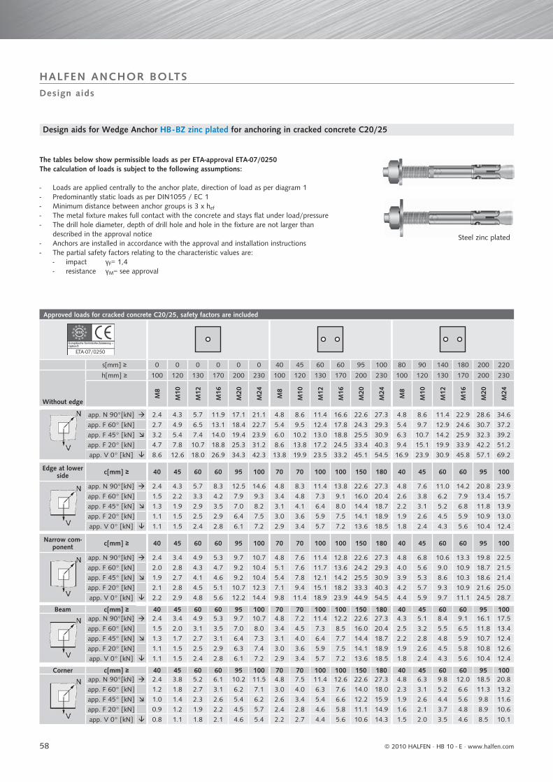
58
Approved loads for cracked concrete C20/25, safety factors are included
ETA-07/0250
s[mm] ≥ 0 0 0 0 0 0 40 45 60 60 95 100 80 90 140 180 200 220
Without edge
h[mm] ≥ 100 120 130 170 200 230 100 120 130 170 200 230 100 120 130 170 200 230
M8
M10
M12
M16
M20
M24
M8
M10
M12
M16
M20
M24
M8
M10
M12
M16
M20
M24
app. N 90°[kN] 2.4 4.3 5.7 11.9 17.1 21.1 4.8 8.6 11.4 16.6 22.6 27.3 4.8 8.6 11.4 22.9 28.6 34.6
app. F 60° [kN] 2.7 4.9 6.5 13.1 18.4 22.7 5.4 9.5 12.4 17.8 24.3 29.3 5.4 9.7 12.9 24.6 30.7 37.2
app. F 45° [kN] 3.2 5.4 7.4 14.0 19.4 23.9 6.0 10.2 13.0 18.8 25.5 30.9 6.3 10.7 14.2 25.9 32.3 39.2
app. F 20° [kN] 4.7 7.8 10.7 18.8 25.3 31.2 8.6 13.8 17.2 24.5 33.4 40.3 9.4 15.1 19.9 33.9 42.2 51.2
app. V 0° [kN] 8.6 12.6 18.0 26.9 34.3 42.3 13.8 19.9 23.5 33.2 45.1 54.5 16.9 23.9 30.9 45.8 57.1 69.2
Edge at lower side c[mm] ≥ 40 45 60 60 95 100 70 70 100 100 150 180 40 45 60 60 95 100
app. N 90°[kN] 2.4 4.3 5.7 8.3 12.5 14.6 4.8 8.3 11.4 13.8 22.6 27.3 4.8 7.6 11.0 14.2 20.8 23.9
app. F 60° [kN] 1.5 2.2 3.3 4.2 7.9 9.3 3.4 4.8 7.3 9.1 16.0 20.4 2.6 3.8 6.2 7.9 13.4 15.7
app. F 45° [kN] 1.3 1.9 2.9 3.5 7.0 8.2 3.1 4.1 6.4 8.0 14.4 18.7 2.2 3.1 5.2 6.8 11.8 13.9
app. F 20° [kN] 1.1 1.5 2.5 2.9 6.4 7.5 3.0 3.6 5.9 7.5 14.1 18.9 1.9 2.6 4.5 5.9 10.9 13.0
app. V 0° [kN] 1.1 1.5 2.4 2.8 6.1 7.2 2.9 3.4 5.7 7.2 13.6 18.5 1.8 2.4 4.3 5.6 10.4 12.4
Narrow com-ponent c[mm] ≥ 40 45 60 60 95 100 70 70 100 100 150 180 40 45 60 60 95 100
app. N 90°[kN] 2.4 3.4 4.9 5.3 9.7 10.7 4.8 7.6 11.4 12.8 22.6 27.3 4.8 6.8 10.6 13.3 19.8 22.5
app. F 60° [kN] 2.0 2.8 4.3 4.7 9.2 10.4 5.1 7.6 11.7 13.6 24.2 29.3 4.0 5.6 9.0 10.9 18.7 21.5
app. F 45° [kN] 1.9 2.7 4.1 4.6 9.2 10.4 5.4 7.8 12.1 14.2 25.5 30.9 3.9 5.3 8.6 10.3 18.6 21.4
app. F 20° [kN] 2.1 2.8 4.5 5.1 10.7 12.3 7.1 9.4 15.1 18.2 33.3 40.3 4.2 5.7 9.3 10.9 21.6 25.0
app. V 0° [kN] 2.2 2.9 4.8 5.6 12.2 14.4 9.8 11.4 18.9 23.9 44.9 54.5 4.4 5.9 9.7 11.1 24.5 28.7
Beam c[mm] ≥ 40 45 60 60 95 100 70 70 100 100 150 180 40 45 60 60 95 100app. N 90°[kN] 2.4 3.4 4.9 5.3 9.7 10.7 4.8 7.2 11.4 12.2 22.6 27.3 4.3 5.1 8.4 9.1 16.1 17.5
app. F 60° [kN] 1.5 2.0 3.1 3.5 7.0 8.0 3.4 4.5 7.3 8.5 16.0 20.4 2.5 3.2 5.5 6.5 11.8 13.4
app. F 45° [kN] 1.3 1.7 2.7 3.1 6.4 7.3 3.1 4.0 6.4 7.7 14.4 18.7 2.2 2.8 4.8 5.9 10.7 12.4
app. F 20° [kN] 1.1 1.5 2.5 2.9 6.3 7.4 3.0 3.6 5.9 7.5 14.1 18.9 1.9 2.6 4.5 5.8 10.8 12.6
app. V 0° [kN] 1.1 1.5 2.4 2.8 6.1 7.2 2.9 3.4 5.7 7.2 13.6 18.5 1.8 2.4 4.3 5.6 10.4 12.4
Corner c[mm] ≥ 40 45 60 60 95 100 70 70 100 100 150 180 40 45 60 60 95 100app. N 90°[kN] 2.4 3.8 5.2 6.1 10.2 11.5 4.8 7.5 11.4 12.6 22.6 27.3 4.8 6.3 9.8 12.0 18.5 20.8
app. F 60° [kN] 1.2 1.8 2.7 3.1 6.2 7.1 3.0 4.0 6.3 7.6 14.0 18.0 2.3 3.1 5.2 6.6 11.3 13.2
app. F 45° [kN] 1.0 1.4 2.3 2.6 5.4 6.2 2.6 3.4 5.4 6.6 12.2 15.9 1.9 2.6 4.4 5.6 9.8 11.6
app. F 20° [kN] 0.9 1.2 1.9 2.2 4.5 5.7 2.4 2.8 4.6 5.8 11.1 14.9 1.6 2.1 3.7 4.8 8.9 10.6
app. V 0° [kN] 0.8 1.1 1.8 2.1 4.6 5.4 2.2 2.7 4.4 5.6 10.6 14.3 1.5 2.0 3.5 4.6 8.5 10.1
1
Design aids
HALFEN ANCHOR BOLTS
Design aids for Wedge Anchor HB - BZ zinc plated for anchoring in cracked concrete C20/25
The tables below show permissible loads as per ETA-approval ETA-07/0250The calculation of loads is subject to the following assumptions:
- Loads are applied centrally to the anchor plate, direction of load as per diagram 1- Predominantly static loads as per DIN1055 / EC 1- Minimum distance between anchor groups is 3 x hef
- The metal fixture makes full contact with the concrete and stays flat under load/pressure- The drill hole diameter, depth of drill hole and hole in the fixture are not larger than described in the approval notice- Anchors are installed in accordance with the approval and installation instructions- The partial safety factors relating to the characteristic values are: - impact γF= 1,4 - resistance γM= see approval
Steel zinc plated
© 2010 HALFEN · HB 10 - E ⋅ www.halfen.com

59
Approved loads for cracked concrete C20/25, safety factors are included
40 45 60 60 95 100 80 90 140 180 200 220 s[mm]
100 120 130 170 200 230 100 120 130 170 200 230 h[mm]
M8
M10
M12
M16
M20
M24
M8
M10
M12
M16
M20
M24
Without edge
8.9 12.4 15.4 20.5 29.7 35.2 9.5 17.1 22.9 39.1 47.6 56.7 app. N 90° [kN] 9.6 13.4 16.5 22.0 32.0 37.2 10.8 18.6 25.4 42.0 51.2 61.0 app. F 60° [kN]10.1 14.1 17.4 23.2 33.6 39.8 11.9 19.7 27.1 44.2 53.9 64.1 app. F 45° [kN]13.2 18.4 22.7 30.3 43.9 52.0 16.9 26.0 36.7 57.8 70.4 83.8 app. F 20° [kN]17.8 24.9 30.7 41.0 59.4 70.3 26.7 35.9 53.0 78.2 95.2 113.4 app. V 0° [kN]
70 70 100 100 150 180 40 45 60 60 95 100 c[mm] Edge at lower side
8.9 10.6 15.4 17.5 29.7 35.2 9.5 12.7 20.8 27.8 37.7 43.2 app. N 90° [kN]4.5 5.3 8.3 10.1 18.2 23.2 3.3 4.4 7.6 9.9 16.9 19.9 app. F 60° [kN]3.7 4.4 7.0 8.6 15.8 20.6 2.5 3.4 6.0 7.7 13.9 16.4 app. F 45° [kN]3.1 3.6 6.0 7.6 14.3 19.3 1.9 2.6 4.6 5.9 11.0 13.2 app. F 20° [kN]2.9 3.4 5.7 7.2 13.6 18.5 1.8 2.4 4.3 5.6 10.4 12.4 app. V 0° [kN]
70 70 100 100 150 180 40 45 60 60 95 100 c[mm] Narrow component
8.9 9.6 15.4 15.8 29.7 35.2 8.6 10.2 18.2 22.7 33.1 36.8 app. N 90° [kN]8.5 9.5 15.3 16.6 31.3 37.8 7.1 8.8 15.7 19.8 31.4 35.8 app. F 60° [kN]8.5 9.6 15.5 17.3 32.6 39.8 6.7 8.4 15.0 19.1 31.3 35.9 app. F 45° [kN]10.1 11.5 18.9 22.1 41.7 52.0 7.1 9.2 16.3 20.9 36.5 42.6 app. F 20° [kN]11.6 13.8 22.7 28.7 54.4 70.3 7.3 9.8 17.2 22.3 41.7 49.8 app. V 0° [kN]
70 70 100 100 150 180 40 45 60 60 95 100 c[mm] Beam8.9 9.6 15.4 15.8 29.7 35.2 8.6 10.2 18.2 22.7 33.1 36.8 app. N 90° [kN]4.5 5.1 8.3 9.7 18.2 23.2 3.2 4.1 7.3 9.4 16.2 18.8 app. F 60° [kN]3.7 4.3 7.0 8.4 15.8 20.6 2.5 3.3 5.9 7.6 13.4 15.8 app. F 45° [kN]3.1 3.6 6.0 7.5 14.3 19.3 1.9 2.6 4.6 5.9 11.0 13.1 app. F 20° [kN]2.9 3.4 5.7 7.2 13.6 18.5 1.8 2.4 4.3 5.6 10.4 12.4 app. V 0° [kN]
70 70 100 100 150 180 40 45 60 60 95 100 c[mm] Corner8.9 9.6 15.4 16.0 29.7 35.2 8.8 10.6 18.5 23.5 33.6 37.7 app. N 90° [kN]3.8 4.3 7.1 8.3 15.7 20.1 2.7 3.6 6.3 8.2 14.1 16.6 app. F 60° [kN]3.0 3.6 5.8 7.0 13.2 17.2 2.0 2.7 4.9 6.4 11.5 13.5 app. F 45° [kN]2.4 2.8 4.7 5.9 11.1 15.0 1.6 2.1 3.7 4.9 9.0 10.7 app. F 20° [kN]2.2 2.7 4.4 5.6 10.6 14.3 1.5 2.0 3.5 4.6 8.5 10.1 app. V 0° [kN]
c
c
s
s chef
d0
tfix
N [kN] 90°
F [kN] 60°F [kN] 45°
F [kN] 20°
V [kN
] 0°
h1
≥ hmin
Design aids
HALFEN ANCHOR BOLTS
Diagram 2
Design aids for Wedge Anchor HB - BZ zinc plated for anchoring in cracked concrete C20/25
Diagram 1
© 2010 HALFEN · HB 10 - E · www.halfen.com

60
Approved loads for cracked concrete C20/25, safety factors are included
ETA07/0249
Without edge
s[mm] ≥ 0 0 0 0 0 40 50 60 60 95 80 90 140 180 200h[mm] ≥ 100 120 130 160 200 100 120 130 160 200 100 120 130 160 200
M8
M10
M12
M16
M20
M8
M10
M12
M16
M20
M8
M10
M12
M16
M20
app. N 90° [kN] 2.4 4.3 5.7 11.9 17.1 4.8 8.6 11.4 16.6 22.6 4.8 8.6 11.4 22.9 28.6
app. F 60° [kN] 2.7 4.8 6.5 13.1 18.4 5.4 9.6 12.4 17.8 24.3 5.4 9.7 12.9 24.6 30.7
app. F 45° [kN] 3.1 5.3 7.3 14.0 19.4 6.0 10.2 13.0 18.8 25.5 6.1 10.6 14.2 25.9 32.3
app. F 20° [kN] 4.4 7.4 10.5 18.8 25.3 8.6 13.9 17.2 24.5 33.4 8.9 14.8 19.9 33.9 42.2
app. V 0° [kN] 7.4 11.4 17.1 26.9 34.3 13.8 20.4 23.5 33.2 45.1 14.9 22.9 30.9 45.8 57.1
Edge at lower side c[mm] ≥ 40 55 60 60 95 70 75 100 100 150 40 55 60 60 95
app. N 90° [kN] 2.4 4.3 5.7 8.3 12.5 4.8 8.6 11.4 13.8 22.6 4.8 8.5 11.0 14.2 20.8
app. F 60° [kN] 1.5 2.6 3.3 4.2 7.9 3.4 5.2 7.3 9.1 16.0 2.6 4.5 6.2 7.9 13.4
app. F 45° [kN] 1.3 2.3 2.9 3.5 7.0 3.1 4.5 6.4 8.0 14.4 2.2 3.8 5.2 6.8 11.8
app. F 20° [kN] 1.1 2.1 2.5 2.9 6.4 3.0 4.0 5.9 7.5 14.1 1.9 3.2 4.5 5.9 10.9
app. V 0° [kN] 1.1 2.0 2.4 2.8 6.1 2.9 3.8 5.7 7.2 13.6 1.8 3.1 4.3 5.6 10.4
Narrow compo-nent c[mm] ≥ 40 55 60 60 95 70 75 100 100 150 40 55 60 60 95
app. N 90° [kN] 2.4 4.3 4.9 5.3 9.7 4.8 8.4 11.4 12.8 22.6 4.8 7.8 10.6 13.3 19.8
app. F 60° [kN] 2.0 3.7 4.3 4.7 9.2 5.1 8.4 11.7 13.6 24.2 4.0 6.9 9.0 10.9 18.7
app. F 45° [kN] 1.9 3.5 4.1 4.6 9.2 5.4 8.6 12.1 14.2 25.5 3.9 6.7 8.6 10.3 18.6
app. F 20° [kN] 2.1 3.8 4.5 5.1 10.7 7.1 10.4 15.1 18.2 33.3 4.2 7.4 9.3 10.9 21.6
app. V 0° [kN] 2.2 4.0 4.8 5.6 12.2 9.8 12.6 18.9 23.9 44.9 4.4 7.9 9.7 11.1 24.5
Beam c[mm] ≥ 40 55 60 60 95 70 75 100 100 150 40 55 60 60 95app. N 90° [kN] 2.4 4.3 4.9 5.3 9.7 4.8 8.1 11.4 12.2 22.6 4.3 6.5 8.4 9.1 16.1
app. F 60° [kN] 1.5 2.6 3.1 3.5 7.0 3.4 5.1 7.3 8.5 16.0 2.5 4.0 5.5 6.5 11.8
app. F 45° [kN] 1.3 2.3 2.7 3.1 6.4 3.1 4.4 6.4 7.7 14.4 2.2 3.5 4.8 5.9 10.7
app. F 20° [kN] 1.1 2.1 2.5 2.9 6.3 3.0 4.0 5.9 7.5 14.1 1.9 3.2 4.5 5.8 10.8
app. V 0° [kN] 1.1 2.0 2.4 2.8 6.1 2.9 3.8 5.7 7.2 13.6 1.8 3.1 4.3 5.6 10.4
Corner c[mm] ≥ 40 55 60 60 95 70 75 100 100 150 40 55 60 60 95app. N 90° [kN] 2.4 4.3 5.2 6.1 10.2 4.8 8.3 11.4 12.6 22.6 4.8 7.4 9.8 12.0 18.5
app. F 60° [kN] 1.2 2.2 2.7 3.1 6.2 3.0 4.4 6.3 7.6 14.0 2.3 3.7 5.2 6.6 11.3
app. F 45° [kN] 1.0 1.9 2.3 2.6 5.4 2.6 3.7 5.4 6.6 12.2 1.9 3.1 4.4 5.6 9.8
app. F 20° [kN] 0.9 1.6 1.9 2.2 4.8 2.4 3.2 4.6 5.8 11.1 1.6 2.6 3.7 4.8 8.9
app. V 0° [kN] 0.8 1.5 1.8 2.1 4.6 2.2 3.0 4.4 5.6 10.6 1.5 2.5 3.5 4.6 8.5
1
Design aids
HALFEN ANCHOR BOLTS
Stainless steel A4Stainless steel HCR 1.4529
The tables below show permissible loads as per ETA-approval ETA-07/0249The calculation of loads is subject to the following assumptions:
- Loads are applied centrally to the anchor plate, direction of load as per diagram 1- Predominantly static loads as per DIN1055 / EC 1- Minimum distance between anchor groups is 3 x hef
- The metal fixture makes full contact with the concrete and stays flat under load/pressure- The drill hole diameter, depth of drill hole and hole in the fixture are not larger than described in the approval notice- Anchors are installed in accordance with the approval and installation instructions- The partial safety factors relating to the characteristic values are: - impact γF= 1,4 - resistance γM= see approval
Design aids for Wedge Anchor HB -BZ A4 and HCR for anchoring in cracked concrete C20/25
© 2010 HALFEN · HB 10 - E ⋅ www.halfen.com

61
Approved loads for cracked concrete C20/25, safety factors are included
40 50 60 60 95 80 90 140 180 200 s[mm]100 120 130 160 200 100 120 130 160 200 h[mm]
M8
M10
M12
M16
M20
M8
M10
M12
M16
M20
Without edge
8.9 13.0 15.4 20.5 29.7 9.5 17.1 22.9 39.1 47.6 app. N 90° [kN] 9.6 14.0 16.5 22.0 32.0 10.8 18.6 25.4 42.0 51.2 app. F 60° [kN]10.1 14.7 17.4 23.2 33.6 11.9 19.7 27.1 44.2 53.9 app. F 45° [kN]13.2 19.2 22.7 30.3 43.9 16.9 26.0 36.7 57.8 70.4 app. F 20° [kN]17.8 26.0 30.7 41.0 59.4 26.7 35.9 53.0 78.2 95.2 app. V 0° [kN]
70 75 100 100 150 40 55 60 60 95 c[mm] Edge at lower side
8.9 11.6 15.4 17.5 29.7 9.5 13.8 20.8 27.8 37.7 app. N 90° [kN]4.5 5.9 8.3 10.1 18.2 3.3 5.3 7.6 9.9 16.9 app. F 60° [kN]3.7 4.9 7.0 8.6 15.8 2.5 4.2 6.0 7.7 13.9 app. F 45° [kN]3.1 4.1 6.0 7.6 14.3 1.9 3.2 4.6 5.9 11.0 app. F 20° [kN]2.9 3.8 5.7 7.2 13.6 1.8 3.1 4.3 5.6 10.4 app. V 0° [kN]
70 75 100 100 150 40 55 60 60 95 c[mm] Narrow component
8.9 10.7 15.4 15.8 29.7 8.6 11.7 18.2 22.7 33.1 app. N 90° [kN]8.5 10.6 15.3 16.6 31.3 7.1 10.5 15.7 19.8 31.4 app. F 60° [kN]8.5 10.7 15.5 17.3 32.6 6.7 10.2 15.0 19.1 31.3 app. F 45° [kN]10.1 12.9 18.9 22.1 41.7 7.1 11.3 16.3 20.9 36.5 app. F 20° [kN]11.6 15.4 22.7 28.7 54.4 7.3 12.2 17.2 22.3 41.7 app. V 0° [kN]
70 75 100 100 150 40 55 60 60 95 c[mm] Beam8.9 10.7 15.4 15.8 29.7 8.6 11.7 18.2 22.7 33.1 app. N 90° [kN]4.5 5.7 8.3 9.7 18.2 3.2 5.1 7.3 9.4 16.2 app. F 60° [kN]3.7 4.8 7.0 8.4 15.8 2.5 4.1 5.9 7.6 13.4 app. F 45° [kN]3.1 4.1 6.0 7.5 14.3 1.9 3.2 4.6 5.9 11.0 app. F 20° [kN]2.9 3.8 5.7 7.2 13.6 1.8 3.1 4.3 5.6 10.4 app. V 0° [kN]
70 75 100 100 150 40 55 60 60 95 c[mm] Corner8.9 10.8 15.4 16.0 29.7 8.8 12.0 18.5 23.5 33.6 app. N 90° [kN]3.8 4.9 7.1 8.3 25.7 2.7 4.3 6.3 8.2 14.1 app. F 60° [kN]3.0 4.0 5.8 7.0 13.2 2.0 3.4 4.9 6.4 11.5 app. F 45° [kN]2.4 3.2 4.7 5.9 11.1 1.6 2.6 3.7 4.9 9.0 app. F 20° [kN]2.2 3.0 4.4 5.6 10.6 1.5 2.5 3.5 4.6 8.5 app. V 0° [kN]
c
c
s
s c
hef
d0
tfix
N [kN] 90°
F [kN] 60°F [kN] 45°
F [kN] 20°
V [kN
] 0°
h1
≥ hmin
Design aids
HALFEN ANCHOR BOLTS
Design aids for Wedge Anchor HB -BZ A4 and HCR for anchoring in cracked concrete C20/25
Diagram 2Diagram 1
© 2010 HALFEN · HB 10 - E · www.halfen.com
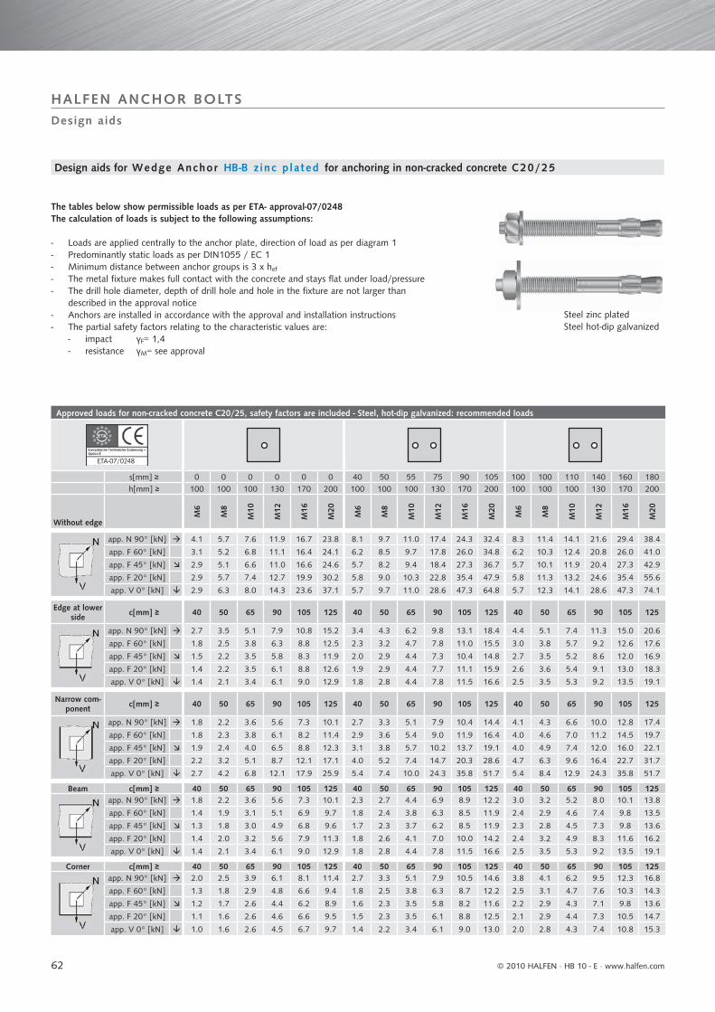
62
Approved loads for non-cracked concrete C20/25, safety factors are included - Steel, hot-dip galvanized: recommended loads
ETA-07/0248
s[mm] ≥ 0 0 0 0 0 0 40 50 55 75 90 105 100 100 110 140 160 180h[mm] ≥ 100 100 100 130 170 200 100 100 100 130 170 200 100 100 100 130 170 200
Without edge
M6
M8
M10
M12
M16
M20
M6
M8
M10
M12
M16
M20
M6
M8
M10
M12
M16
M20
app. N 90° [kN] 4.1 5.7 7.6 11.9 16.7 23.8 8.1 9.7 11.0 17.4 24.3 32.4 8.3 11.4 14.1 21.6 29.4 38.4
app. F 60° [kN] 3.1 5.2 6.8 11.1 16.4 24.1 6.2 8.5 9.7 17.8 26.0 34.8 6.2 10.3 12.4 20.8 26.0 41.0
app. F 45° [kN] 2.9 5.1 6.6 11.0 16.6 24.6 5.7 8.2 9.4 18.4 27.3 36.7 5.7 10.1 11.9 20.4 27.3 42.9
app. F 20° [kN] 2.9 5.7 7.4 12.7 19.9 30.2 5.8 9.0 10.3 22.8 35.4 47.9 5.8 11.3 13.2 24.6 35.4 55.6
app. V 0° [kN] 2.9 6.3 8.0 14.3 23.6 37.1 5.7 9.7 11.0 28.6 47.3 64.8 5.7 12.3 14.1 28.6 47.3 74.1
Edge at lower side c[mm] ≥ 40 50 65 90 105 125 40 50 65 90 105 125 40 50 65 90 105 125
app. N 90° [kN] 2.7 3.5 5.1 7.9 10.8 15.2 3.4 4.3 6.2 9.8 13.1 18.4 4.4 5.1 7.4 11.3 15.0 20.6
app. F 60° [kN] 1.8 2.5 3.8 6.3 8.8 12.5 2.3 3.2 4.7 7.8 11.0 15.5 3.0 3.8 5.7 9.2 12.6 17.6
app. F 45° [kN] 1.5 2.2 3.5 5.8 8.3 11.9 2.0 2.9 4.4 7.3 10.4 14.8 2.7 3.5 5.2 8.6 12.0 16.9
app. F 20° [kN] 1.4 2.2 3.5 6.1 8.8 12.6 1.9 2.9 4.4 7.7 11.1 15.9 2.6 3.6 5.4 9.1 13.0 18.3
app. V 0° [kN] 1.4 2.1 3.4 6.1 9.0 12.9 1.8 2.8 4.4 7.8 11.5 16.6 2.5 3.5 5.3 9.2 13.5 19.1
Narrow com-ponent c[mm] ≥ 40 50 65 90 105 125 40 50 65 90 105 125 40 50 65 90 105 125
app. N 90° [kN] 1.8 2.2 3.6 5.6 7.3 10.1 2.7 3.3 5.1 7.9 10.4 14.4 4.1 4.3 6.6 10.0 12.8 17.4
app. F 60° [kN] 1.8 2.3 3.8 6.1 8.2 11.4 2.9 3.6 5.4 9.0 11.9 16.4 4.0 4.6 7.0 11.2 14.5 19.7
app. F 45° [kN] 1.9 2.4 4.0 6.5 8.8 12.3 3.1 3.8 5.7 10.2 13.7 19.1 4.0 4.9 7.4 12.0 16.0 22.1
app. F 20° [kN] 2.2 3.2 5.1 8.7 12.1 17.1 4.0 5.2 7.4 14.7 20.3 28.6 4.7 6.3 9.6 16.4 22.7 31.7
app. V 0° [kN] 2.7 4.2 6.8 12.1 17.9 25.9 5.4 7.4 10.0 24.3 35.8 51.7 5.4 8.4 12.9 24.3 35.8 51.7
Beam c[mm] ≥ 40 50 65 90 105 125 40 50 65 90 105 125 40 50 65 90 105 125app. N 90° [kN] 1.8 2.2 3.6 5.6 7.3 10.1 2.3 2.7 4.4 6.9 8.9 12.2 3.0 3.2 5.2 8.0 10.1 13.8
app. F 60° [kN] 1.4 1.9 3.1 5.1 6.9 9.7 1.8 2.4 3.8 6.3 8.5 11.9 2.4 2.9 4.6 7.4 9.8 13.5
app. F 45° [kN] 1.3 1.8 3.0 4.9 6.8 9.6 1.7 2.3 3.7 6.2 8.5 11.9 2.3 2.8 4.5 7.3 9.8 13.6
app. F 20° [kN] 1.4 2.0 3.2 5.6 7.9 11.3 1.8 2.6 4.1 7.0 10.0 14.2 2.4 3.2 4.9 8.3 11.6 16.2
app. V 0° [kN] 1.4 2.1 3.4 6.1 9.0 12.9 1.8 2.8 4.4 7.8 11.5 16.6 2.5 3.5 5.3 9.2 13.5 19.1
Corner c[mm] ≥ 40 50 65 90 105 125 40 50 65 90 105 125 40 50 65 90 105 125app. N 90° [kN] 2.0 2.5 3.9 6.1 8.1 11.4 2.7 3.3 5.1 7.9 10.5 14.6 3.8 4.1 6.2 9.5 12.3 16.8
app. F 60° [kN] 1.3 1.8 2.9 4.8 6.6 9.4 1.8 2.5 3.8 6.3 8.7 12.2 2.5 3.1 4.7 7.6 10.3 14.3
app. F 45° [kN] 1.2 1.7 2.6 4.4 6.2 8.9 1.6 2.3 3.5 5.8 8.2 11.6 2.2 2.9 4.3 7.1 9.8 13.6
app. F 20° [kN] 1.1 1.6 2.6 4.6 6.6 9.5 1.5 2.3 3.5 6.1 8.8 12.5 2.1 2.9 4.4 7.3 10.5 14.7
app. V 0° [kN] 1.0 1.6 2.6 4.5 6.7 9.7 1.4 2.2 3.4 6.1 9.0 13.0 2.0 2.8 4.3 7.4 10.8 15.3
7
Design aids
HALFEN ANCHOR BOLTS
The tables below show permissible loads as per ETA- approval-07/0248 The calculation of loads is subject to the following assumptions:
- Loads are applied centrally to the anchor plate, direction of load as per diagram 1- Predominantly static loads as per DIN1055 / EC 1- Minimum distance between anchor groups is 3 x hef
- The metal fixture makes full contact with the concrete and stays flat under load/pressure- The drill hole diameter, depth of drill hole and hole in the fixture are not larger than described in the approval notice- Anchors are installed in accordance with the approval and installation instructions- The partial safety factors relating to the characteristic values are: - impact γF= 1,4 - resistance γM= see approval
Design aids for Wedge Anchor HB -B z inc p lated for anchoring in non-cracked concrete C20/25
Steel zinc platedSteel hot-dip galvanized
© 2010 HALFEN · HB 10 - E ⋅ www.halfen.com
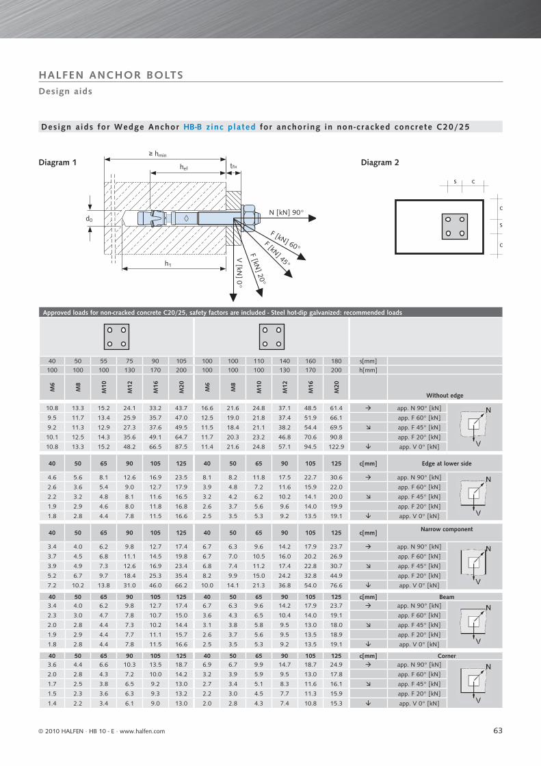
63
Approved loads for non-cracked concrete C20/25, safety factors are included - Steel hot-dip galvanized: recommended loads
40 50 55 75 90 105 100 100 110 140 160 180 s[mm]100 100 100 130 170 200 100 100 100 130 170 200 h[mm]
M6
M8
M10
M12
M16
M20
M6
M8
M10
M12
M16
M20
Without edge
10.8 13.3 15.2 24.1 33.2 43.7 16.6 21.6 24.8 37.1 48.5 61.4 app. N 90° [kN]
9.5 11.7 13.4 25.9 35.7 47.0 12.5 19.0 21.8 37.4 51.9 66.1 app. F 60° [kN]
9.2 11.3 12.9 27.3 37.6 49.5 11.5 18.4 21.1 38.2 54.4 69.5 app. F 45° [kN]
10.1 12.5 14.3 35.6 49.1 64.7 11.7 20.3 23.2 46.8 70.6 90.8 app. F 20° [kN]
10.8 13.3 15.2 48.2 66.5 87.5 11.4 21.6 24.8 57.1 94.5 122.9 app. V 0° [kN]
40 50 65 90 105 125 40 50 65 90 105 125 c[mm] Edge at lower side
4.6 5.6 8.1 12.6 16.9 23.5 8.1 8.2 11.8 17.5 22.7 30.6 app. N 90° [kN]
2.6 3.6 5.4 9.0 12.7 17.9 3.9 4.8 7.2 11.6 15.9 22.0 app. F 60° [kN]
2.2 3.2 4.8 8.1 11.6 16.5 3.2 4.2 6.2 10.2 14.1 20.0 app. F 45° [kN]
1.9 2.9 4.6 8.0 11.8 16.8 2.6 3.7 5.6 9.6 14.0 19.9 app. F 20° [kN]
1.8 2.8 4.4 7.8 11.5 16.6 2.5 3.5 5.3 9.2 13.5 19.1 app. V 0° [kN]
40 50 65 90 105 125 40 50 65 90 105 125 c[mm] Narrow component
3.4 4.0 6.2 9.8 12.7 17.4 6.7 6.3 9.6 14.2 17.9 23.7 app. N 90° [kN]
3.7 4.5 6.8 11.1 14.5 19.8 6.7 7.0 10.5 16.0 20.2 26.9 app. F 60° [kN]
3.9 4.9 7.3 12.6 16.9 23.4 6.8 7.4 11.2 17.4 22.8 30.7 app. F 45° [kN]
5.2 6.7 9.7 18.4 25.3 35.4 8.2 9.9 15.0 24.2 32.8 44.9 app. F 20° [kN]
7.2 10.2 13.8 31.0 46.0 66.2 10.0 14.1 21.3 36.8 54.0 76.6 app. V 0° [kN]
40 50 65 90 105 125 40 50 65 90 105 125 c[mm] Beam3.4 4.0 6.2 9.8 12.7 17.4 6.7 6.3 9.6 14.2 17.9 23.7 app. N 90° [kN]
2.3 3.0 4.7 7.8 10.7 15.0 3.6 4.3 6.5 10.4 14.0 19.1 app. F 60° [kN]
2.0 2.8 4.4 7.3 10.2 14.4 3.1 3.8 5.8 9.5 13.0 18.0 app. F 45° [kN]
1.9 2.9 4.4 7.7 11.1 15.7 2.6 3.7 5.6 9.5 13.5 18.9 app. F 20° [kN]
1.8 2.8 4.4 7.8 11.5 16.6 2.5 3.5 5.3 9.2 13.5 19.1 app. V 0° [kN]
40 50 65 90 105 125 40 50 65 90 105 125 c[mm] Corner3.6 4.4 6.6 10.3 13.5 18.7 6.9 6.7 9.9 14.7 18.7 24.9 app. N 90° [kN]
2.0 2.8 4.3 7.2 10.0 14.2 3.2 3.9 5.9 9.5 13.0 17.8 app. F 60° [kN]
1.7 2.5 3.8 6.5 9.2 13.0 2.7 3.4 5.1 8.3 11.6 16.1 app. F 45° [kN]
1.5 2.3 3.6 6.3 9.3 13.2 2.2 3.0 4.5 7.7 11.3 15.9 app. F 20° [kN]
1.4 2.2 3.4 6.1 9.0 13.0 2.0 2.8 4.3 7.4 10.8 15.3 app. V 0° [kN]
c
c
s
s c
hef
d0
tfix
N [kN] 90°
F [kN] 60°F [kN] 45°
F [kN] 20°
V [kN
] 0°
h1
≥ hmin
Design aids
HALFEN ANCHOR BOLTS
Diagram 2
Des ign a ids for Wedge Anchor HB -B z inc p lated for anchor ing in non-cracked concrete C20/25
Diagram 1
© 2010 HALFEN · HB 10 - E · www.halfen.com
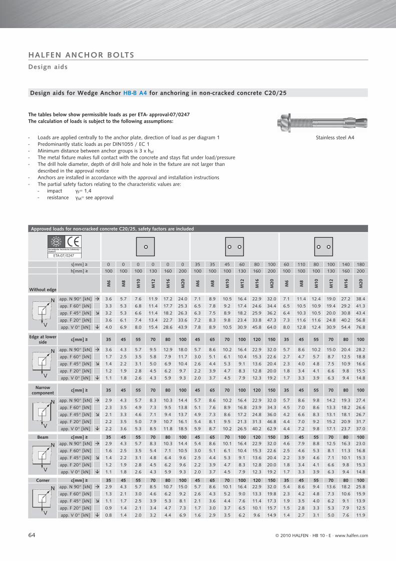
64
Approved loads for non-cracked concrete C20/25, safety factors are included
ETA-07/0247
s[mm] ≥ 0 0 0 0 0 0 35 35 45 60 80 100 60 110 80 100 140 180h[mm] ≥ 100 100 100 130 160 200 100 100 100 130 160 200 100 100 100 130 160 200
Without edge
M6
M8
M10
M12
M16
M20
M6
M8
M10
M12
M16
M20
M6
M8
M10
M12
M16
M20
app. N 90° [kN] 3.6 5.7 7.6 11.9 17.2 24.0 7.1 8.9 10.5 16.4 22.9 32.0 7.1 11.4 12.4 19.0 27.2 38.4
app. F 60° [kN] 3.3 5.3 6.8 11.4 17.7 25.3 6.5 7.8 9.2 17.4 24.6 34.4 6.5 10.5 10.9 19.4 29.2 41.3
app. F 45° [kN] 3.2 5.3 6.6 11.4 18.2 26.3 6.3 7.5 8.9 18.2 25.9 36.2 6.4 10.3 10.5 20.0 30.8 43.4
app. F 20° [kN] 3.6 6.1 7.4 13.4 22.7 33.6 7.2 8.3 9.8 23.4 33.8 47.3 7.3 11.6 11.6 24.8 40.2 56.8
app. V 0° [kN] 4.0 6.9 8.0 15.4 28.6 43.9 7.8 8.9 10.5 30.9 45.8 64.0 8.0 12.8 12.4 30.9 54.4 76.8
Edge at lower side c[mm] ≥ 35 45 55 70 80 100 45 65 70 100 120 150 35 45 55 70 80 100
app. N 90° [kN] 3.6 4.3 5.7 9.5 12.9 18.0 5.7 8.6 10.2 16.4 22.9 32.0 5.7 8.6 10.2 15.0 20.4 28.2
app. F 60° [kN] 1.7 2.5 3.5 5.8 7.9 11.7 3.0 5.1 6.1 10.4 15.3 22.6 2.7 4.7 5.7 8.7 12.5 18.8
app. F 45° [kN] 1.4 2.2 3.1 5.0 6.9 10.4 2.6 4.4 5.3 9.1 13.6 20.4 2.3 4.0 4.8 7.5 10.9 16.6
app. F 20° [kN] 1.2 1.9 2.8 4.5 6.2 9.7 2.2 3.9 4.7 8.3 12.8 20.0 1.8 3.4 4.1 6.6 9.8 15.5
app. V 0° [kN] 1.1 1.8 2.6 4.3 5.9 9.3 2.0 3.7 4.5 7.9 12.3 19.2 1.7 3.3 3.9 6.3 9.4 14.8
Narrow component c[mm] ≥ 35 45 55 70 80 100 45 65 70 100 120 150 35 45 55 70 80 100
app. N 90° [kN] 2.9 4.3 5.7 8.3 10.3 14.4 5.7 8.6 10.2 16.4 22.9 32.0 5.7 8.6 9.8 14.2 19.3 27.4
app. F 60° [kN] 2.3 3.5 4.9 7.3 9.5 13.8 5.1 7.6 8.9 16.8 23.9 34.3 4.5 7.0 8.6 13.3 18.2 26.6
app. F 45° [kN] 2.1 3.3 4.6 7.1 9.4 13.7 4.9 7.3 8.6 17.2 24.8 36.0 4.2 6.6 8.3 13.1 18.1 26.7
app. F 20° [kN] 2.2 3.5 5.0 7.9 10.7 16.1 5.4 8.1 9.5 21.3 31.3 46.8 4.4 7.0 9.2 15.2 20.9 31.7
app. V 0° [kN] 2.2 3.6 5.3 8.5 11.8 18.5 5.9 8.7 10.2 26.5 40.2 62.9 4.4 7.2 9.8 17.1 23.7 37.0
Beam c[mm] ≥ 35 45 55 70 80 100 45 65 70 100 120 150 35 45 55 70 80 100app. N 90° [kN] 2.9 4.3 5.7 8.3 10.3 14.4 5.4 8.6 10.1 16.4 22.9 32.0 4.6 7.9 8.8 12.5 16.3 23.0
app. F 60° [kN] 1.6 2.5 3.5 5.4 7.1 10.5 3.0 5.1 6.1 10.4 15.3 22.6 2.5 4.6 5.3 8.1 11.3 16.8
app. F 45° [kN] 1.4 2.2 3.1 4.8 6.4 9.6 2.5 4.4 5.3 9.1 13.6 20.4 2.2 3.9 4.6 7.1 10.1 15.3
app. F 20° [kN] 1.2 1.9 2.8 4.5 6.2 9.6 2.2 3.9 4.7 8.3 12.8 20.0 1.8 3.4 4.1 6.6 9.8 15.3
app. V 0° [kN] 1.1 1.8 2.6 4.3 5.9 9.3 2.0 3.7 4.5 7.9 12.3 19.2 1.7 3.3 3.9 6.3 9.4 14.8
Corner c[mm] ≥ 35 45 55 70 80 100 45 65 70 100 120 150 35 45 55 70 80 100app. N 90° [kN] 2.9 4.3 5.7 8.5 10.7 15.0 5.7 8.6 10.1 16.4 22.9 32.0 5.4 8.6 9.4 13.6 18.2 25.8
app. F 60° [kN] 1.3 2.1 3.0 4.6 6.2 9.2 2.6 4.3 5.2 9.0 13.3 19.8 2.3 4.2 4.8 7.3 10.6 15.9
app. F 45° [kN] 1.1 1.7 2.5 3.9 5.3 8.1 2.1 3.6 4.4 7.6 11.4 17.3 1.9 3.5 4.0 6.2 9.1 13.9
app. F 20° [kN] 0.9 1.4 2.1 3.4 4.7 7.3 1.7 3.0 3.7 6.5 10.1 15.7 1.5 2.8 3.3 5.3 7.9 12.5
app. V 0° [kN] 0.8 1.4 2.0 3.2 4.4 6.9 1.6 2.9 3.5 6.2 9.6 14.9 1.4 2.7 3.1 5.0 7.6 11.9
7
Design aids
HALFEN ANCHOR BOLTS
The tables below show permissible loads as per ETA- approval-07/0247The calculation of loads is subject to the following assumptions:
- Loads are applied centrally to the anchor plate, direction of load as per diagram 1- Predominantly static loads as per DIN1055 / EC 1- Minimum distance between anchor groups is 3 x hef
- The metal fixture makes full contact with the concrete and stays flat under load/pressure- The drill hole diameter, depth of drill hole and hole in the fixture are not larger than described in the approval notice- Anchors are installed in accordance with the approval and installation instructions- The partial safety factors relating to the characteristic values are: - impact γF= 1,4 - resistance γM= see approval
Stainless steel A4
Design aids for Wedge Anchor HB -B A4 for anchoring in non-cracked concrete C20/25
© 2010 HALFEN · HB 10 - E ⋅ www.halfen.com

65
Approved loads for non-cracked concrete C20/25, safety factors are included
35 35 45 60 80 100 60 110 80 100 140 180 s[mm]100 100 100 130 160 200 100 100 100 130 160 200 h[mm]
M6
M8
M10
M12
M16
M20
M6
M8
M10
M12
M16
M20
Without edge
10.1 11.2 13.7 21.5 30.5 42.7 13.7 22.9 19.3 28.8 43.1 61.4 app. N 90° [kN]
8.9 9.8 12.1 23.1 32.8 45.9 12.0 20.3 17.0 31.0 46.3 66.1 app. F 60° [kN]
8.6 9.5 11.7 24.3 34.5 48.3 11.6 19.7 16.4 32.6 48.7 69.5 app. F 45° [kN]
9.5 10.5 12.9 31.8 45.1 63.1 12.8 21.9 18.1 42.5 63.6 90.8 app. F 20° [kN]
10.1 11.2 13.7 43.0 61.1 85.3 13.7 23.5 19.3 57.6 86.1 122.9 app. V 0° [kN]
45 65 70 100 120 150 35 45 55 70 80 100 c[mm] Edge at lower side
8.5 11.1 13.5 21.5 30.5 42.7 10.3 17.1 16.6 23.9 34.7 49.5 app. N 90° [kN]
3.5 5.6 6.8 11.6 17.4 25.9 3.2 5.9 6.7 10.4 15.3 23.4 app. F 60° [kN]
2.8 4.7 5.7 9.8 14.9 22.5 2.4 4.5 5.4 8.5 12.5 19.3 app. F 45° [kN]
2.2 3.9 4.7 8.4 12.9 20.2 1.9 3.5 4.2 6.7 9.9 15.7 app. F 20° [kN]
2.0 3.7 4.5 7.9 12.3 19.2 1.7 3.3 3.9 6.3 9.4 14.8 app. V 0° [kN]
45 65 70 100 120 150 35 45 55 70 80 100 c[mm] Narrow component
7.6 11.0 13.3 21.5 30.5 42.7 8.6 17.1 15.2 21.4 30.6 43.8 app. N 90° [kN]
y
6.6 9.7 11.7 21.4 31.1 44.8 7.0 13.5 13.4 19.9 28.8 42.5 app. F 60° [kN]
6.4 9.4 11.3 21.8 32.0 46.6 6.6 12.6 12.9 19.7 28.6 42.7 app. F 45° [kN]
7.1 10.3 12.5 26.4 39.6 59.3 6.9 13.1 14.3 22.5 33.1 50.7 app. F 20° [kN]
7.6 11.0 13.3 31.8 49.2 76.9 7.0 13.1 15.2 25.2 37.5 59.2 app. V 0° [kN]
45 65 70 100 120 150 35 45 55 70 80 100 c[mm] Beam7.6 11.0 13.3 21.5 30.5 42.7 8.6 17.1 15.2 21.4 30.6 43.8 app. N 90° [kN]
3.3 5.6 6.8 11.6 17.4 25.9 3.1 5.9 6.5 10.0 14.7 22.4 app. F 60° [kN]
2.7 4.7 5.7 9.8 14.9 22.5 2.4 4.5 5.3 8.3 12.2 18.8 app. F 45° [kN]
2.2 3.9 4.7 8.4 12.9 20.2 1.9 3.5 4.2 6.7 9.9 15.6 app. F 20° [kN]
2.0 3.7 4.5 7.9 12.3 19.2 1.7 3.3 3.9 6.3 9.4 14.8 app. V 0° [kN]
45 65 70 100 120 150 35 45 55 70 80 100 c[mm] Corner7.6 11.0 13.3 21.5 30.5 42.7 8.9 17.1 15.3 21.7 31.0 44.4 app. N 90° [kN]
2.8 4.7 5.7 9.9 14.9 22.3 2.6 5.0 5.6 8.6 12.7 19.5 app. F 60° [kN]
2.2 3.8 4.7 8.1 12.4 18.8 2.0 3.7 4.4 6.9 10.3 16.0 app. F 45° [kN]
1.7 3.0 3.7 6.5 10.1 15.8 1.5 2.8 3.3 5.3 8.0 12.6 app. F 20° [kN]
1.6 2.9 3.5 6.2 9.6 14.9 1.4 2.7 3.1 5.0 7.6 11.9 app. V 0° [kN]
c
c
s
s c
hef
d0
tfix
N [kN] 90°
F [kN] 60°F [kN] 45°
F [kN] 20°
V [kN
] 0°
h1
≥ hmin
Design aids
HALFEN ANCHOR BOLTS
Diagram 2
Design aids for Wedge Anchor HB -B A4 for anchoring in non-cracked concrete C20/25
Diagram 1
© 2010 HALFEN · HB 10 - E · www.halfen.com
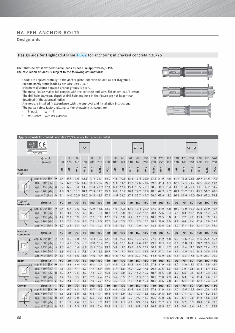
66
Approved loads for cracked concrete C20/25, safety factors are included
ETA09/0416
Without edge
s[mm] ≥ 0 0 0 0 0 0 0 50 60 70 80 100 100 125 100 120 175 200 220 220 540h[mm] ≥ 100 120 140 160 200 230 250 100 120 140 160 200 230 250 100 120 140 160 200 230 250
M6
M8
M10
M12
M16
M16
L
M20
M6
M8
M10
M12
M16
M16
L
M20
M6
M8
M10
M12
M16
M16
L
M20
app. N 90° [kN] 2.4 5.7 7.6 12.3 17.1 21.1 24.0 4.8 10.6 13.6 16.4 22.9 27.3 31.9 4.8 11.4 15.2 22.5 29.7 34.6 47.9app. F 60° [kN] 2.7 6.4 8.6 13.2 18.4 22.7 25.8 5.4 11.4 14.7 17.6 24.6 29.3 34.3 5.4 12.7 17.1 24.2 32.0 37.2 51.5app. F 45° [kN] 3.2 6.9 9.4 13.9 19.4 23.9 27.1 6.1 12.0 15.4 18.5 25.9 30.9 36.1 6.4 13.6 18.4 25.4 33.6 39.2 54.2app. F 20° [kN] 4.9 9.5 13.2 18.1 25.3 31.2 35.4 8.8 15.7 20.1 24.2 33.8 40.3 47.2 9.7 18.4 25.2 33.2 43.9 51.2 70.8app. V 0° [kN] 9.1 14.0 20.5 24.5 34.3 42.3 47.9 14.5 21.2 27.3 32.7 45.7 54.5 63.9 18.2 26.6 37.4 45.0 59.4 69.2 95.8
Edge at lower side c[mm] ≥ 50 60 70 80 100 100 180 80 100 120 160 180 180 300 50 60 70 80 100 100 180
app. N 90° [kN] 2.4 5.7 7.6 9.2 12.9 14.6 23.2 4.8 10.6 13.6 16.4 22.9 27.3 31.9 4.8 10.0 13.9 16.9 22.3 23.9 46.4app. F 60° [kN] 1.8 3.3 4.5 5.8 8.6 9.3 18.2 3.7 6.8 9.2 12.2 17.5 20.4 27.6 3.3 5.6 8.3 10.6 15.0 15.7 36.5
app. F 45° [kN] 1.7 2.9 3.9 5.0 7.7 8.2 17.0 3.5 6.0 8.2 11.2 16.2 18.7 26.5 3.0 4.8 7.2 9.2 13.3 13.9 33.9
app. F 20° [kN] 1.7 2.5 3.5 4.6 7.3 7.5 17.6 3.6 5.5 7.8 11.3 16.6 18.9 29.0 2.9 4.2 6.4 8.4 12.6 13.0 35.1
app. V 0° [kN] 1.7 2.4 3.3 4.4 7.0 7.2 17.5 3.6 5.3 7.5 11.0 16.4 18.5 30.6 2.8 4.0 6.1 8.0 12.1 12.4 35.1
Narrow component c[mm] ≥ 50 60 70 80 100 100 180 80 100 120 160 180 180 300 50 60 70 80 100 100 180
app. N 90° [kN] 2.4 4.8 6.0 7.4 10.3 10.7 22.7 4.8 10.6 13.6 16.4 22.9 27.3 31.9 4.8 9.6 13.6 16.6 21.6 22.5 46.4
app. F 60° [kN] 2.3 4.2 5.5 6.9 10.0 10.4 22.9 5.4 10.9 14.4 17.6 24.6 29.3 34.3 4.7 8.4 11.8 14.8 20.7 21.5 46.5
app. F 45° [kN] 2.3 4.0 5.4 6.8 10.1 10.4 23.4 5.8 11.3 15.0 18.5 25.9 30.9 36.1 4.7 8.1 11.4 14.5 20.7 21.4 47.4
app. F 20° [kN] 2.8 4.5 6.1 7.8 11.9 12.3 28.7 7.9 14.0 19.2 24.2 33.8 40.3 47.2 5.6 8.9 12.5 16.2 24.3 25.0 57.8
app. V 0° [kN] 3.3 4.8 6.6 8.8 14.0 14.4 35.1 11.8 17.7 25.2 32.7 45.7 54.5 63.9 6.6 9.5 13.3 17.5 27.9 28.7 70.2
Beam c[mm] ≥ 50 60 70 80 100 100 180 80 100 120 160 180 180 300 50 60 70 80 100 100 180app. N 90° [kN] 2.4 4.8 6.0 7.4 10.3 10.7 22.7 4.8 10.6 13.6 16.4 22.9 27.3 31.9 4.8 8.0 11.0 13.5 17.8 17.5 45.4
app. F 60° [kN] 1.8 3.1 4.1 5.2 7.7 8.0 18.0 3.7 6.8 9.2 12.2 17.5 20.4 27.6 3.3 5.1 7.5 9.5 13.4 13.4 36.0
app. F 45° [kN] 1.7 2.7 3.6 4.7 7.1 7.3 16.8 3.5 6.0 8.2 11.2 16.2 18.7 26.5 3.0 4.5 6.6 8.5 12.2 12.4 33.6
app. F 20° [kN] 1.7 2.5 3.5 4.6 7.2 7.4 17.5 3.6 5.5 7.8 11.3 16.6 18.9 29.0 2.9 4.2 6.3 8.4 12.4 12.6 35.0app. V 0° [kN] 1.7 2.4 3.3 4.4 7.0 7.2 17.5 3.6 5.3 7.5 11.0 16.4 18.5 30.6 2.8 4.0 6.1 8.0 12.1 12.4 35.1
Corner c[mm] ≥ 50 60 70 80 100 100 180 80 100 120 160 180 180 300 50 60 70 80 100 100 180app. N 90° [kN] 2.4 5.0 6.3 7.7 10.7 11.5 22.7 4.8 10.6 13.6 16.4 22.9 27.3 31.9 4.8 9.0 12.6 15.3 20.1 20.8 45.9
app. F 60° [kN] 1.6 2.6 3.5 4.5 6.8 7.1 15.8 3.3 5.9 8.0 10.7 15.5 18.0 24.8 3.0 4.8 7.1 9.1 12.8 13.2 36.7
app. F 45° [kN] 1.4 2.2 3.0 3.9 6.0 6.2 14.1 3.0 5.0 6.9 9.5 13.8 15.9 23.0 2.6 4.0 6.1 7.8 11.2 11.6 32.4
app. F 20° [kN] 1.3 1.9 2.6 3.5 5.5 5.7 13.7 2.9 4.3 6.1 8.9 13.2 14.9 23.7 2.3 3.4 5.2 6.9 10.3 10.6 30.3
app. V 0° [kN] 1.2 1.8 2.5 3.3 5.2 5.4 13.2 2.8 4.1 5.8 8.5 12.7 14.3 23.5 2.2 3.2 5.0 6.6 9.8 10.1 28.9
Design aids for Highload Anchor HB -SZ for anchoring in cracked concrete C20/25
The tables below show permissible loads as per ETA- approval-09/0416 The calculation of loads is subject to the following assumptions:
- Loads are applied centrally to the anchor plate, direction of load as per diagram 1- Predominantly static loads as per DIN1055 / EC 1- Minimum distance between anchor groups is 3 x hef
- The metal fixture makes full contact with the concrete and stays flat under load/pressure- The drill hole diameter, depth of drill hole and hole in the fixture are not larger than described in the approval notice- Anchors are installed in accordance with the approval and installation instructions- The partial safety factors relating to the characteristic values are: - impact γF= 1,4 - resistance γM= see approval
Design aids
HALFEN ANCHOR BOLTS
© 2010 HALFEN · HB 10 - E ⋅ www.halfen.com
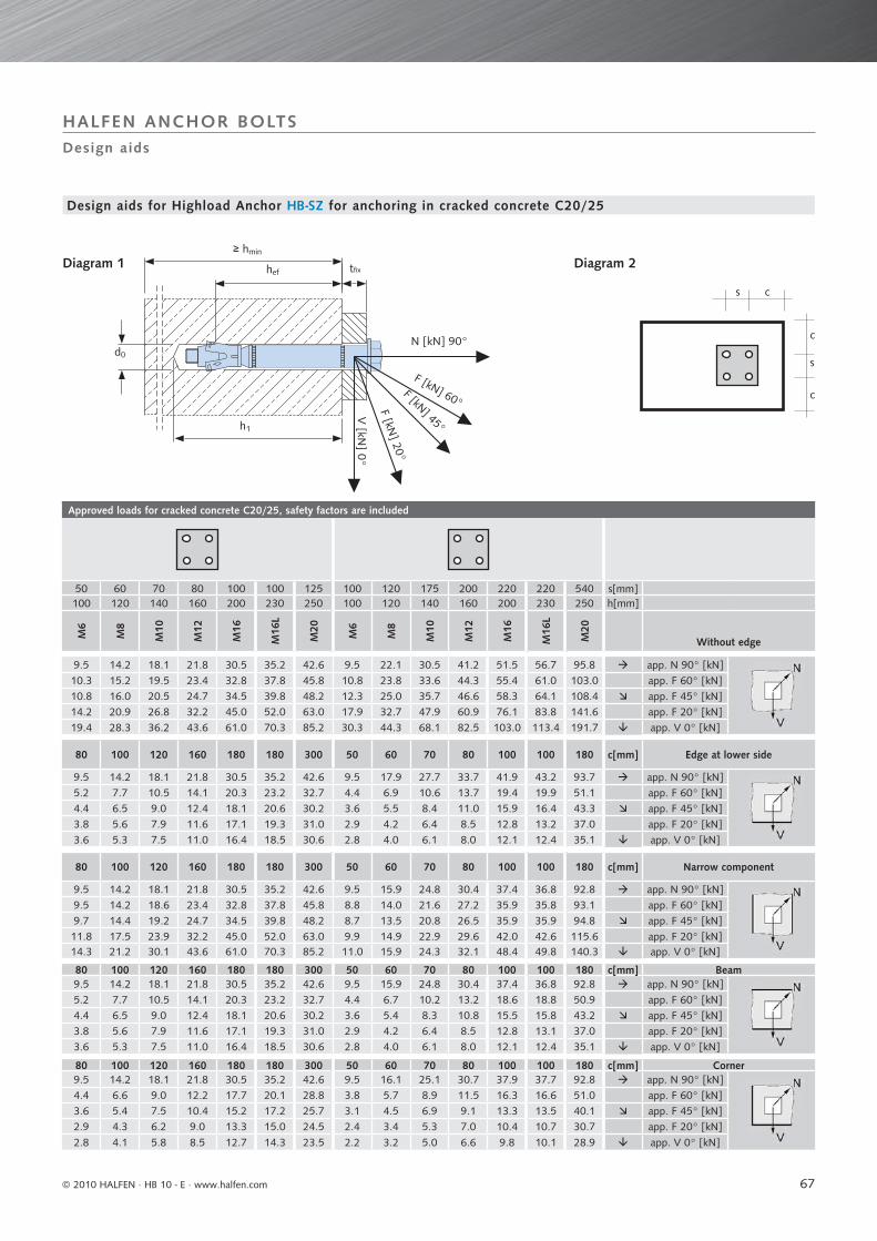
67
Approved loads for cracked concrete C20/25, safety factors are included
50 60 70 80 100 100 125 100 120 175 200 220 220 540 s[mm]100 120 140 160 200 230 250 100 120 140 160 200 230 250 h[mm]
M6
M8
M10
M12
M16
M16
L
M20
M6
M8
M10
M12
M16
M16
L
M20
Without edge
9.5 14.2 18.1 21.8 30.5 35.2 42.6 9.5 22.1 30.5 41.2 51.5 56.7 95.8 app. N 90° [kN] 10.3 15.2 19.5 23.4 32.8 37.8 45.8 10.8 23.8 33.6 44.3 55.4 61.0 103.0 app. F 60° [kN]10.8 16.0 20.5 24.7 34.5 39.8 48.2 12.3 25.0 35.7 46.6 58.3 64.1 108.4 app. F 45° [kN]14.2 20.9 26.8 32.2 45.0 52.0 63.0 17.9 32.7 47.9 60.9 76.1 83.8 141.6 app. F 20° [kN]19.4 28.3 36.2 43.6 61.0 70.3 85.2 30.3 44.3 68.1 82.5 103.0 113.4 191.7 app. V 0° [kN]
80 100 120 160 180 180 300 50 60 70 80 100 100 180 c[mm] Edge at lower side
9.5 14.2 18.1 21.8 30.5 35.2 42.6 9.5 17.9 27.7 33.7 41.9 43.2 93.7 app. N 90° [kN]5.2 7.7 10.5 14.1 20.3 23.2 32.7 4.4 6.9 10.6 13.7 19.4 19.9 51.1 app. F 60° [kN]4.4 6.5 9.0 12.4 18.1 20.6 30.2 3.6 5.5 8.4 11.0 15.9 16.4 43.3 app. F 45° [kN]3.8 5.6 7.9 11.6 17.1 19.3 31.0 2.9 4.2 6.4 8.5 12.8 13.2 37.0 app. F 20° [kN]3.6 5.3 7.5 11.0 16.4 18.5 30.6 2.8 4.0 6.1 8.0 12.1 12.4 35.1 app. V 0° [kN]
80 100 120 160 180 180 300 50 60 70 80 100 100 180 c[mm] Narrow component
9.5 14.2 18.1 21.8 30.5 35.2 42.6 9.5 15.9 24.8 30.4 37.4 36.8 92.8 app. N 90° [kN]9.5 14.2 18.6 23.4 32.8 37.8 45.8 8.8 14.0 21.6 27.2 35.9 35.8 93.1 app. F 60° [kN]9.7 14.4 19.2 24.7 34.5 39.8 48.2 8.7 13.5 20.8 26.5 35.9 35.9 94.8 app. F 45° [kN]11.8 17.5 23.9 32.2 45.0 52.0 63.0 9.9 14.9 22.9 29.6 42.0 42.6 115.6 app. F 20° [kN]14.3 21.2 30.1 43.6 61.0 70.3 85.2 11.0 15.9 24.3 32.1 48.4 49.8 140.3 app. V 0° [kN]
80 100 120 160 180 180 300 50 60 70 80 100 100 180 c[mm] Beam9.5 14.2 18.1 21.8 30.5 35.2 42.6 9.5 15.9 24.8 30.4 37.4 36.8 92.8 app. N 90° [kN]5.2 7.7 10.5 14.1 20.3 23.2 32.7 4.4 6.7 10.2 13.2 18.6 18.8 50.9 app. F 60° [kN]4.4 6.5 9.0 12.4 18.1 20.6 30.2 3.6 5.4 8.3 10.8 15.5 15.8 43.2 app. F 45° [kN]3.8 5.6 7.9 11.6 17.1 19.3 31.0 2.9 4.2 6.4 8.5 12.8 13.1 37.0 app. F 20° [kN]3.6 5.3 7.5 11.0 16.4 18.5 30.6 2.8 4.0 6.1 8.0 12.1 12.4 35.1 app. V 0° [kN]
80 100 120 160 180 180 300 50 60 70 80 100 100 180 c[mm] Corner9.5 14.2 18.1 21.8 30.5 35.2 42.6 9.5 16.1 25.1 30.7 37.9 37.7 92.8 app. N 90° [kN]4.4 6.6 9.0 12.2 17.7 20.1 28.8 3.8 5.7 8.9 11.5 16.3 16.6 51.0 app. F 60° [kN]3.6 5.4 7.5 10.4 15.2 17.2 25.7 3.1 4.5 6.9 9.1 13.3 13.5 40.1 app. F 45° [kN]2.9 4.3 6.2 9.0 13.3 15.0 24.5 2.4 3.4 5.3 7.0 10.4 10.7 30.7 app. F 20° [kN]2.8 4.1 5.8 8.5 12.7 14.3 23.5 2.2 3.2 5.0 6.6 9.8 10.1 28.9 app. V 0° [kN]
c
c
s
s c
hef
d0
tfix
N [kN] 90°
F [kN] 60°F [kN] 45°
F [kN] 20°
V [kN
] 0°
h1
≥ hmin
Design aids for Highload Anchor HB -SZ for anchoring in cracked concrete C20/25
Design aids
HALFEN ANCHOR BOLTS
Diagram 2Diagram 1
© 2010 HALFEN · HB 10 - E · www.halfen.com
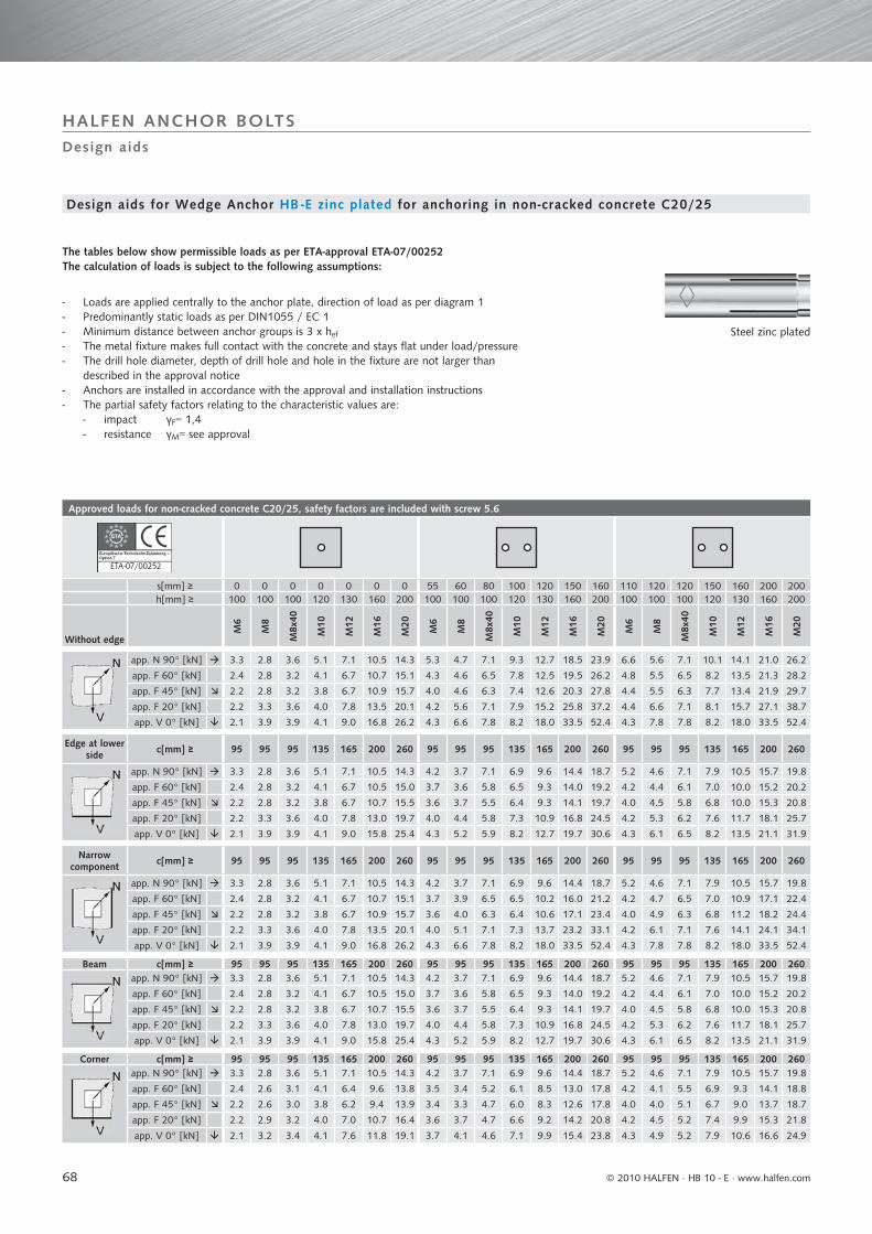
68
Approved loads for non-cracked concrete C20/25, safety factors are included with screw 5.6
s[mm] ≥ 0 0 0 0 0 0 0 55 60 80 100 120 150 160 110 120 120 150 160 200 200h[mm] ≥ 100 100 100 120 130 160 200 100 100 100 120 130 160 200 100 100 100 120 130 160 200
Without edge
M6
M8
M8x
40
M10
M12
M16
M20
M6
M8
M8x
40
M10
M12
M16
M20
M6
M8
M8x
40
M10
M12
M16
M20
app. N 90° [kN] 3.3 2.8 3.6 5.1 7.1 10.5 14.3 5.3 4.7 7.1 9.3 12.7 18.5 23.9 6.6 5.6 7.1 10.1 14.1 21.0 26.2
app. F 60° [kN] 2.4 2.8 3.2 4.1 6.7 10.7 15.1 4.3 4.6 6.5 7.8 12.5 19.5 26.2 4.8 5.5 6.5 8.2 13.5 21.3 28.2
app. F 45° [kN] 2.2 2.8 3.2 3.8 6.7 10.9 15.7 4.0 4.6 6.3 7.4 12.6 20.3 27.8 4.4 5.5 6.3 7.7 13.4 21.9 29.7
app. F 20° [kN] 2.2 3.3 3.6 4.0 7.8 13.5 20.1 4.2 5.6 7.1 7.9 15.2 25.8 37.2 4.4 6.6 7.1 8.1 15.7 27.1 38.7
app. V 0° [kN] 2.1 3.9 3.9 4.1 9.0 16.8 26.2 4.3 6.6 7.8 8.2 18.0 33.5 52.4 4.3 7.8 7.8 8.2 18.0 33.5 52.4
Edge at lower side c[mm] ≥ 95 95 95 135 165 200 260 95 95 95 135 165 200 260 95 95 95 135 165 200 260
app. N 90° [kN] 3.3 2.8 3.6 5.1 7.1 10.5 14.3 4.2 3.7 7.1 6.9 9.6 14.4 18.7 5.2 4.6 7.1 7.9 10.5 15.7 19.8
app. F 60° [kN] 2.4 2.8 3.2 4.1 6.7 10.5 15.0 3.7 3.6 5.8 6.5 9.3 14.0 19.2 4.2 4.4 6.1 7.0 10.0 15.2 20.2
app. F 45° [kN] 2.2 2.8 3.2 3.8 6.7 10.7 15.5 3.6 3.7 5.5 6.4 9.3 14.1 19.7 4.0 4.5 5.8 6.8 10.0 15.3 20.8
app. F 20° [kN] 2.2 3.3 3.6 4.0 7.8 13.0 19.7 4.0 4.4 5.8 7.3 10.9 16.8 24.5 4.2 5.3 6.2 7.6 11.7 18.1 25.7
app. V 0° [kN] 2.1 3.9 3.9 4.1 9.0 15.8 25.4 4.3 5.2 5.9 8.2 12.7 19.7 30.6 4.3 6.1 6.5 8.2 13.5 21.1 31.9
Narrow component c[mm] ≥ 95 95 95 135 165 200 260 95 95 95 135 165 200 260 95 95 95 135 165 200 260
app. N 90° [kN] 3.3 2.8 3.6 5.1 7.1 10.5 14.3 4.2 3.7 7.1 6.9 9.6 14.4 18.7 5.2 4.6 7.1 7.9 10.5 15.7 19.8
app. F 60° [kN] 2.4 2.8 3.2 4.1 6.7 10.7 15.1 3.7 3.9 6.5 6.5 10.2 16.0 21.2 4.2 4.7 6.5 7.0 10.9 17.1 22.4
app. F 45° [kN] 2.2 2.8 3.2 3.8 6.7 10.9 15.7 3.6 4.0 6.3 6.4 10.6 17.1 23.4 4.0 4.9 6.3 6.8 11.2 18.2 24.4
app. F 20° [kN] 2.2 3.3 3.6 4.0 7.8 13.5 20.1 4.0 5.1 7.1 7.3 13.7 23.2 33.1 4.2 6.1 7.1 7.6 14.1 24.1 34.1
app. V 0° [kN] 2.1 3.9 3.9 4.1 9.0 16.8 26.2 4.3 6.6 7.8 8.2 18.0 33.5 52.4 4.3 7.8 7.8 8.2 18.0 33.5 52.4
Beam c[mm] ≥ 95 95 95 135 165 200 260 95 95 95 135 165 200 260 95 95 95 135 165 200 260app. N 90° [kN] 3.3 2.8 3.6 5.1 7.1 10.5 14.3 4.2 3.7 7.1 6.9 9.6 14.4 18.7 5.2 4.6 7.1 7.9 10.5 15.7 19.8
app. F 60° [kN] 2.4 2.8 3.2 4.1 6.7 10.5 15.0 3.7 3.6 5.8 6.5 9.3 14.0 19.2 4.2 4.4 6.1 7.0 10.0 15.2 20.2
app. F 45° [kN] 2.2 2.8 3.2 3.8 6.7 10.7 15.5 3.6 3.7 5.5 6.4 9.3 14.1 19.7 4.0 4.5 5.8 6.8 10.0 15.3 20.8
app. F 20° [kN] 2.2 3.3 3.6 4.0 7.8 13.0 19.7 4.0 4.4 5.8 7.3 10.9 16.8 24.5 4.2 5.3 6.2 7.6 11.7 18.1 25.7
app. V 0° [kN] 2.1 3.9 3.9 4.1 9.0 15.8 25.4 4.3 5.2 5.9 8.2 12.7 19.7 30.6 4.3 6.1 6.5 8.2 13.5 21.1 31.9
Corner c[mm] ≥ 95 95 95 135 165 200 260 95 95 95 135 165 200 260 95 95 95 135 165 200 260app. N 90° [kN] 3.3 2.8 3.6 5.1 7.1 10.5 14.3 4.2 3.7 7.1 6.9 9.6 14.4 18.7 5.2 4.6 7.1 7.9 10.5 15.7 19.8
app. F 60° [kN] 2.4 2.6 3.1 4.1 6.4 9.6 13.8 3.5 3.4 5.2 6.1 8.5 13.0 17.8 4.2 4.1 5.5 6.9 9.3 14.1 18.8
app. F 45° [kN] 2.2 2.6 3.0 3.8 6.2 9.4 13.9 3.4 3.3 4.7 6.0 8.3 12.6 17.8 4.0 4.0 5.1 6.7 9.0 13.7 18.7
app. F 20° [kN] 2.2 2.9 3.2 4.0 7.0 10.7 16.4 3.6 3.7 4.7 6.6 9.2 14.2 20.8 4.2 4.5 5.2 7.4 9.9 15.3 21.8
app. V 0° [kN] 2.1 3.2 3.4 4.1 7.6 11.8 19.1 3.7 4.1 4.6 7.1 9.9 15.4 23.8 4.3 4.9 5.2 7.9 10.6 16.6 24.9
ETA-07/002527
Design aids
HALFEN ANCHOR BOLTS
Steel zinc plated
The tables below show permissible loads as per ETA-approval ETA-07/00252The calculation of loads is subject to the following assumptions:
- Loads are applied centrally to the anchor plate, direction of load as per diagram 1- Predominantly static loads as per DIN1055 / EC 1- Minimum distance between anchor groups is 3 x hef
- The metal fixture makes full contact with the concrete and stays flat under load/pressure- The drill hole diameter, depth of drill hole and hole in the fixture are not larger than described in the approval notice- Anchors are installed in accordance with the approval and installation instructions- The partial safety factors relating to the characteristic values are: - impact γF= 1,4 - resistance γM= see approval
Design aids for Wedge Anchor HB -E zinc plated for anchoring in non-cracked concrete C20/25
© 2010 HALFEN · HB 10 - E ⋅ www.halfen.com
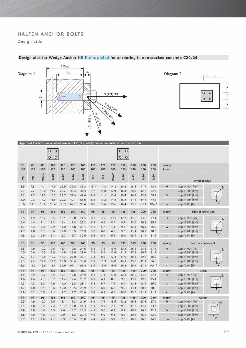
69
Approved loads for non-cracked concrete C20/25, safety factors are included with screw 5.6
55 60 80 100 120 150 160 110 120 120 150 160 200 200 s[mm]100 100 100 120 130 160 200 100 100 100 120 130 160 200 h[mm]
M6
M8
M8x
40
M10
M12
M16
M20
M6
M8
M8x
40
M10
M12
M16
M20
Without edge
8.5 7.8 14.1 17.0 22.9 32.8 39.8 13.1 11.3 14.3 20.2 28.3 41.9 48.1 app. N 90° [kN]
7.5 7.7 12.8 14.7 23.2 35.4 44.4 9.7 11.0 12.9 16.4 26.9 42.7 52.7 app. F 60° [kN]
7.2 7.7 12.5 14.2 23.7 37.4 47.6 8.8 11.1 12.6 15.4 26.9 43.8 55.9 app. F 45° [kN]
8.0 9.3 14.2 15.5 29.2 49.1 65.0 8.8 13.2 14.2 16.2 31.4 54.1 74.6 app. F 20° [kN]
8.6 11.0 15.6 16.4 35.9 67.1 95.4 8.6 15.6 15.6 16.4 35.9 67.1 104.7 app. V 0° [kN]
95 95 95 135 165 200 260 95 95 95 135 165 200 260 c[mm] Edge at lower side
5.5 4.9 10.2 9.5 13.1 19.8 24.5 8.2 7.5 13.5 12.2 15.6 23.6 27.4 app. N 90° [kN]
4.6 4.4 7.1 8.2 11.4 17.4 23.2 6.2 6.1 8.5 9.9 13.0 19.8 25.4 app. F 60° [kN]
4.3 4.3 6.3 7.9 11.0 16.8 23.1 5.6 5.7 7.4 9.4 12.3 18.9 25.0 app. F 45° [kN]
4.7 4.8 6.1 8.6 12.0 18.5 26.9 5.7 6.0 6.8 9.9 13.1 20.3 28.6 app. F 20° [kN]
4.8 5.2 5.9 9.1 12.7 19.7 30.6 5.6 6.1 6.5 10.0 13.5 21.1 31.9 app. V 0° [kN]
95 95 95 135 165 200 260 95 95 95 135 165 200 260 c[mm] Narrow component
5.5 4.9 10.2 9.5 13.1 19.8 24.5 8.2 7.5 13.5 12.2 15.6 23.6 27.4 app. N 90° [kN]5.5 5.4 10.3 9.9 14.9 22.6 28.0 7.3 8.1 12.4 11.9 17.3 26.7 31.3 app. F 60° [kN]
5.7 5.7 10.5 10.2 16.3 26.0 33.1 7.1 8.6 12.3 11.9 18.5 29.6 36.9 app. F 45° [kN]
7.0 7.7 12.8 12.9 23.0 38.4 50.4 7.9 11.3 14.0 14.1 25.0 42.1 56.0 app. F 20° [kN]
8.6 11.0 15.6 16.4 35.9 67.1 95.4 8.6 15.6 15.6 16.4 35.9 67.1 104.7 app. V 0° [kN]
95 95 95 135 165 200 260 95 95 95 135 165 200 260 c[mm] Beam5.5 4.9 10.2 9.5 13.1 19.8 24.5 8.2 7.5 13.5 12.2 15.6 23.6 27.4 app. N 90° [kN]
4.6 4.4 7.1 8.2 11.4 17.4 23.2 6.2 6.1 8.5 9.9 13.0 19.8 25.4 app. F 60° [kN]
4.3 4.3 6.3 7.9 11.0 16.8 23.1 5.6 5.7 7.4 9.4 12.3 18.9 25.0 app. F 45° [kN]
4.7 4.8 6.1 8.6 12.0 18.5 26.9 5.7 6.0 6.8 9.9 13.1 20.3 28.6 app. F 20° [kN]
4.8 5.2 5.9 9.1 12.7 19.7 30.6 5.6 6.1 6.5 10.0 13.5 21.1 31.9 app. V 0° [kN]
95 95 95 135 165 200 260 95 95 95 135 165 200 260 c[mm] Corner5.5 4.9 10.2 9.5 13.1 19.8 24.5 8.2 7.5 13.5 12.2 15.6 23.6 27.4 app. N 90° [kN]
4.1 4.0 6.2 7.4 10.3 15.8 21.3 5.5 5.5 7.5 9.0 11.7 17.9 23.2 app. F 60° [kN]
3.8 3.8 5.4 6.9 9.6 14.7 20.5 4.9 5.0 6.3 8.2 10.7 16.5 22.2 app. F 45° [kN]
3.8 4.0 4.8 7.1 9.9 15.3 22.4 4.6 5.0 5.4 8.2 10.9 16.9 23.9 app. F 20° [kN]
3.7 4.1 4.6 7.1 9.9 15.4 23.8 4.4 4.9 5.2 7.9 10.6 16.6 24.9 app. V 0° [kN]
c
c
s
s chef
d0
tfix
N [kN] 90°
F [kN] 60°F [kN] 45°
F [kN] 20°
V [kN
] 0°
≥ hmin
Design aids
HALFEN ANCHOR BOLTS
Diagram 2
Design aids for Wedge Anchor HB -E zinc plated for anchoring in non-cracked concrete C20/25
Diagram 1
© 2010 HALFEN · HB 10 - E · www.halfen.com
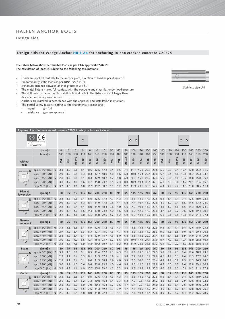
70
Approved loads for non-cracked concrete C20/25, safety factors are included
ETA-007/0251
s[mm] ≥ 0 0 0 0 0 0 0 50 60 80 100 120 150 160 100 120 120 150 160 200 200h[mm] ≥ 100 100 100 130 140 160 250 100 100 100 130 140 160 250 100 100 100 130 140 160 250
Without edge
M6
M8
M8x
40
M10
M12
M16
M20
M6
M8
M8x
40
M10
M12
M16
M20
M6
M8
M8x
40
M10
M12
M16
M20
app. N 90° [kN] 3.3 3.3 3.6 6.1 8.5 12.6 17.2 5.1 5.5 7.1 11.1 15.3 22.3 28.6 6.6 6.6 7.1 12.1 17.0 25.2 31.5
app. F 60° [kN] 2.9 3.2 3.4 5.3 8.3 12.7 18.0 4.8 5.6 6.8 10.0 15.4 23.1 30.8 5.7 6.4 6.8 10.6 16.7 25.3 33.7
app. F 45° [kN] 2.8 3.2 3.4 5.1 8.4 12.9 18.7 4.7 5.8 6.8 9.8 15.8 23.9 32.4 5.5 6.5 6.8 10.2 16.8 25.8 35.3
app. F 20° [kN] 3.0 3.9 4.0 5.6 10.1 15.8 23.7 5.5 7.3 8.0 10.9 19.4 30.1 42.3 6.0 7.8 8.0 11.2 20.1 31.6 45.8
app. V 0° [kN] 3.2 4.6 4.6 6.0 11.9 19.2 30.7 6.1 9.2 9.2 11.9 23.8 38.5 57.2 6.4 9.2 9.2 11.9 23.8 38.5 61.4
Edge at lower side c[mm] ≥ 80 95 95 135 165 200 260 80 95 95 135 165 200 260 80 95 95 135 165 200 260
app. N 90° [kN] 3.3 3.3 3.6 6.1 8.5 12.6 17.2 4.3 4.3 7.1 8.3 11.6 17.3 22.5 5.3 5.4 7.1 9.4 12.6 18.9 23.8
app. F 60° [kN] 2.9 3.2 3.4 5.3 8.1 11.9 17.8 3.8 4.1 5.8 7.7 10.7 15.9 22.8 4.6 4.9 6.1 8.6 11.5 17.2 24.0
app. F 45° [kN] 2.8 3.2 3.4 5.1 8.0 11.9 18.4 3.6 4.0 5.5 7.6 10.5 15.6 23.4 4.4 4.9 5.8 8.5 11.3 16.9 24.6
app. F 20° [kN] 3.0 3.7 4.0 5.6 9.4 13.8 23.2 4.0 4.6 5.8 8.6 12.0 17.8 28.8 4.7 5.5 6.2 9.6 12.8 19.1 30.2
app. V 0° [kN] 3.2 4.3 4.6 6.0 10.7 15.8 29.5 4.2 5.2 5.9 9.6 13.3 19.7 35.5 5.0 6.1 6.5 10.6 14.2 21.1 37.1
Narrow component c[mm] ≥ 80 95 95 135 165 200 260 80 95 95 135 165 200 260 80 95 95 135 165 200 260
app. N 90° [kN] 3.3 3.3 3.6 6.1 8.5 12.6 17.2 4.3 4.3 7.1 8.3 11.3 17.3 22.5 5.3 5.4 7.1 9.4 12.6 18.9 23.8
app. F 60° [kN] 2.9 3.2 3.4 5.3 8.3 12.7 18.0 4.3 4.7 6.8 8.2 12.5 19.0 25.3 5.0 5.6 6.8 9.0 13.4 20.4 26.8
app. F 45° [kN] 2.8 3.2 3.4 5.1 8.4 12.9 18.7 4.3 5.0 6.8 8.3 13.2 20.2 27.4 4.9 5.7 6.8 8.9 14.0 21.5 29.1
app. F 20° [kN] 3.0 3.9 4.0 5.6 10.1 15.8 23.7 5.2 6.6 8.0 10.0 17.4 27.1 37.9 5.7 7.2 8.0 10.4 18.0 28.2 40.4
app. V 0° [kN] 3.2 4.6 4.6 6.0 11.9 19.2 30.7 6.1 9.2 9.2 11.9 23.8 38.5 57.2 6.4 9.2 9.2 11.9 23.8 38.5 61.4
Beam c[mm] ≥ 80 95 95 135 165 200 260 80 95 95 135 165 200 260 80 95 95 135 165 200 260app. N 90° [kN] 3.3 3.3 3.6 6.1 8.5 12.6 17.2 4.3 4.3 7.1 8.3 11.6 17.3 22.5 5.3 5.4 7.1 9.4 12.6 18.9 23.8
app. F 60° [kN] 2.9 3.2 3.4 5.3 8.1 11.9 17.8 3.8 4.1 5.8 7.7 10.7 15.9 22.8 4.6 4.9 6.1 8.6 11.5 17.2 24.0
app. F 45° [kN] 2.8 3.2 3.4 5.1 8.0 11.9 18.4 3.6 4.0 5.5 7.6 10.5 15.6 23.4 4.4 4.9 5.8 8.5 11.3 16.9 24.6
app. F 20° [kN] 3.0 3.7 4.0 5.6 9.4 13.8 23.2 4.0 4.6 5.8 8.6 12.0 17.8 28.8 4.7 5.5 6.2 9.6 12.8 19.1 30.2
app. V 0° [kN] 3.2 4.3 4.6 6.0 10.7 15.8 29.5 4.2 5.2 5.9 9.6 13.3 19.7 35.5 5.0 6.1 6.5 10.6 14.2 21.1 37.1
Corner c[mm] ≥ 80 95 95 135 165 200 260 80 95 95 135 165 200 260 80 95 95 135 165 200 260app. N 90° [kN] 3.3 3.3 3.6 6.1 8.5 12.6 17.2 4.3 4.3 7.1 8.3 11.6 17.3 22.5 5.3 5.4 7.1 9.4 12.6 18.9 23.8
app. F 60° [kN] 2.6 2.9 3.1 5.2 7.3 10.8 16.4 3.4 3.7 5.2 7.0 9.8 14.5 21.2 4.2 4.5 5.5 7.9 10.6 15.8 22.3
app. F 45° [kN] 2.5 2.8 3.0 5.0 7.0 10.4 16.4 3.2 3.6 4.7 6.7 9.3 13.8 21.0 3.8 4.3 5.1 7.5 10.0 15.0 22.1
app. F 20° [kN] 2.6 3.0 3.2 5.5 7.6 11.3 19.2 3.3 3.9 4.7 7.2 10.0 14.9 24.3 4.0 4.7 5.2 8.1 10.8 16.0 25.6
app. V 0° [kN] 2.6 3.2 3.4 5.8 8.0 11.8 22.1 3.3 4.1 4.6 7.5 10.4 15.4 27.6 3.9 4.9 5.2 8.4 11.2 16.6 28.9
7
Design aids
HALFEN ANCHOR BOLTS
Stainless steel A4
The tables below show permissible loads as per ETA- approval-07/0251The calculation of loads is subject to the following assumptions:
- Loads are applied centrally to the anchor plate, direction of load as per diagram 1- Predominantly static loads as per DIN1055 / EC 1- Minimum distance between anchor groups is 3 x hef
- The metal fixture makes full contact with the concrete and stays flat under load/pressure- The drill hole diameter, depth of drill hole and hole in the fixture are not larger than described in the approval notice- Anchors are installed in accordance with the approval and installation instructions- The partial safety factors relating to the characteristic values are: - impact γF= 1,4 - resistance γM= see approval
Design aids for Wedge Anchor HB -E A4 for anchoring in non-cracked concrete C20/25
© 2010 HALFEN · HB 10 - E ⋅ www.halfen.com
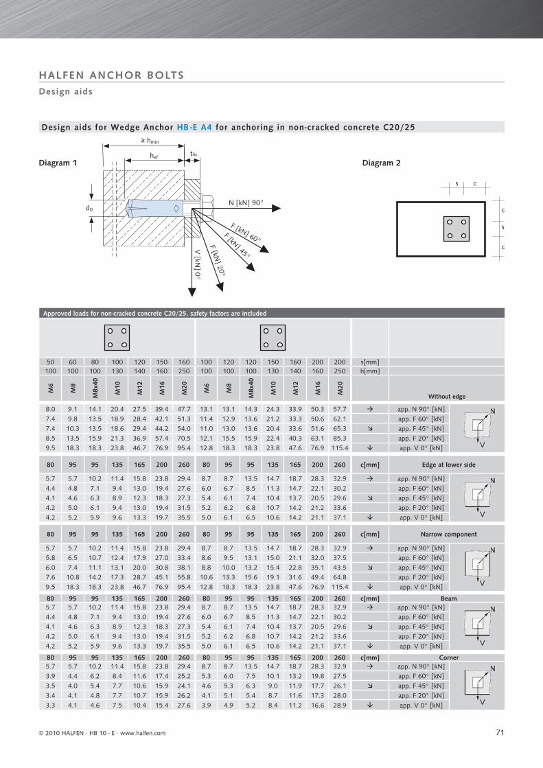
71
Approved loads for non-cracked concrete C20/25, safety factors are included
50 60 80 100 120 150 160 100 120 120 150 160 200 200 s[mm]100 100 100 130 140 160 250 100 100 100 130 140 160 250 h[mm]
M6
M8
M8x
40
M10
M12
M16
M20
M6
M8
M8x
40
M10
M12
M16
M20
Without edge
8.0 9.1 14.1 20.4 27.5 39.4 47.7 13.1 13.1 14.3 24.3 33.9 50.3 57.7 app. N 90° [kN] 7.4 9.8 13.5 18.9 28.4 42.1 51.3 11.4 12.9 13.6 21.2 33.3 50.6 62.1 app. F 60° [kN]7.4 10.3 13.5 18.6 29.4 44.2 54.0 11.0 13.0 13.6 20.4 33.6 51.6 65.3 app. F 45° [kN]8.5 13.5 15.9 21.3 36.9 57.4 70.5 12.1 15.5 15.9 22.4 40.3 63.1 85.3 app. F 20° [kN]9.5 18.3 18.3 23.8 46.7 76.9 95.4 12.8 18.3 18.3 23.8 47.6 76.9 115.4 app. V 0° [kN]
80 95 95 135 165 200 260 80 95 95 135 165 200 260 c[mm] Edge at lower side
5.7 5.7 10.2 11.4 15.8 23.8 29.4 8.7 8.7 13.5 14.7 18.7 28.3 32.9 app. N 90° [kN]4.4 4.8 7.1 9.4 13.0 19.4 27.6 6.0 6.7 8.5 11.3 14.7 22.1 30.2 app. F 60° [kN]4.1 4.6 6.3 8.9 12.3 18.3 27.3 5.4 6.1 7.4 10.4 13.7 20.5 29.6 app. F 45° [kN]4.2 5.0 6.1 9.4 13.0 19.4 31.5 5.2 6.2 6.8 10.7 14.2 21.2 33.6 app. F 20° [kN]4.2 5.2 5.9 9.6 13.3 19.7 35.5 5.0 6.1 6.5 10.6 14.2 21.1 37.1 app. V 0° [kN]
80 95 95 135 165 200 260 80 95 95 135 165 200 260 c[mm] Narrow component
5.7 5.7 10.2 11.4 15.8 23.8 29.4 8.7 8.7 13.5 14.7 18.7 28.3 32.9 app. N 90° [kN]5.8 6.5 10.7 12.4 17.9 27.0 33.4 8.6 9.5 13.1 15.0 21.1 32.0 37.5 app. F 60° [kN]6.0 7.4 11.1 13.1 20.0 30.8 38.1 8.8 10.0 13.2 15.4 22.8 35.1 43.5 app. F 45° [kN]7.6 10.8 14.2 17.3 28.7 45.1 55.8 10.6 13.3 15.6 19.1 31.6 49.4 64.8 app. F 20° [kN]9.5 18.3 18.3 23.8 46.7 76.9 95.4 12.8 18.3 18.3 23.8 47.6 76.9 115.4 app. V 0° [kN]
80 95 95 135 165 200 260 80 95 95 135 165 200 260 c[mm] Beam5.7 5.7 10.2 11.4 15.8 23.8 29.4 8.7 8.7 13.5 14.7 18.7 28.3 32.9 app. N 90° [kN]4.4 4.8 7.1 9.4 13.0 19.4 27.6 6.0 6.7 8.5 11.3 14.7 22.1 30.2 app. F 60° [kN]4.1 4.6 6.3 8.9 12.3 18.3 27.3 5.4 6.1 7.4 10.4 13.7 20.5 29.6 app. F 45° [kN]4.2 5.0 6.1 9.4 13.0 19.4 31.5 5.2 6.2 6.8 10.7 14.2 21.2 33.6 app. F 20° [kN]4.2 5.2 5.9 9.6 13.3 19.7 35.5 5.0 6.1 6.5 10.6 14.2 21.1 37.1 app. V 0° [kN]
80 95 95 135 165 200 260 80 95 95 135 165 200 260 c[mm] Corner5.7 5.7 10.2 11.4 15.8 23.8 29.4 8.7 8.7 13.5 14.7 18.7 28.3 32.9 app. N 90° [kN]3.9 4.4 6.2 8.4 11.6 17.4 25.2 5.3 6.0 7.5 10.1 13.2 19.8 27.5 app. F 60° [kN]3.5 4.0 5.4 7.7 10.6 15.9 24.1 4.6 5.3 6.3 9.0 11.9 17.7 26.1 app. F 45° [kN]3.4 4.1 4.8 7.7 10.7 15.9 26.2 4.1 5.1 5.4 8.7 11.6 17.3 28.0 app. F 20° [kN]3.3 4.1 4.6 7.5 10.4 15.4 27.6 3.9 4.9 5.2 8.4 11.2 16.6 28.9 app. V 0° [kN]
c
c
s
s c
hef
d0
tfix
N [kN] 90°
F [kN] 60°F [kN] 45°
F [kN] 20°
V [kN
] 0°
≥ hmin
Design aids
HALFEN ANCHOR BOLTS
Diagram 2
Design aids for Wedge Anchor HB -E A4 for anchoring in non-cracked concrete C20/25
Diagram 1
© 2010 HALFEN · HB 10 - E · www.halfen.com
© 2
010
HA
LFEN
Gm
bH, G
erm
any
appl
ies
also
to
copy
ing
in e
xtra
cts.
B - 0
23 -
E - 0
8/10
x.
xxx
08/
10
CONTACT HALFEN WORLDWIDE
HALFEN is represented by subs id iar ies in the fo l lowing 14 countr ies , p lease contact us :
NOTES REGARDING THIS CATALOGUETechnical and design changes reserved. The information in this publication is based on state-of-the-art technology at the time of publica-tion. We reserve the right to make technical and design changes at any time. HALFEN GmbH shall not accept liability for the accuracy of the information in this publication or for any printing errors.
The Quality Management System of Halfen GmbH is certified for the locations in Germany, Austria, Poland, Switzerland and the Czech Republic according to DIN EN ISO 9001:2008, Certificate No. QS-281 HH.
Austria HALFEN Gesellschaft m.b.H.Leonard-Bernstein-Str. 101220 Wien
Phone: +43 - 1 - 259 6770 E-Mail: [email protected]: www.halfen.at
Fax: +43 - 1 - 259 - 6770 99
Belgium/Luxembourg HALFEN N.V.Borkelstraat 1312900 Schoten
Phone: +32 - 3 - 658 07 20E-Mail: [email protected]: www.halfen.be
Fax: +32 - 3 - 658 15 33
China HALFEN Construction Accessories Distribution Co.Ltd.Room 601 Tower D, Vantone CentreNo.A6 Chao Yang Men Wai StreetChaoyang District Beijing · P.R. China 100020
Phone: +86 - 10 5907 3200E-Mail: [email protected]: www.halfen.cn
Fax: +86 - 10 5907 3218
Czech Republic HALFEN-DEHA s.r.o.K Vypichu 986 · Komerčni zóna Rudná, hala 625219 Rudná
Phone: +420 - 311 - 690 060E-Mail: [email protected]: www.halfen-deha.cz
Fax: +420 - 311 - 671 416
France HALFEN S.A.S.18, rue Goubet75019 Paris
Phone: +33 - 1 - 445231 00E-Mail: [email protected]: www.halfen.fr
Fax: +33 - 1 - 445231 52
Germany HALFEN Vertriebsgesellschaft mbHKatzbergstrasse 3 40764 Langenfeld
Phone: +49 - 2173 - 970 0E-Mail: [email protected]: www.halfen.de
Fax: +49 - 2173 - 970 225
Italy HALFEN-DEHA S.r.l. Soc. UnipersonaleVia F.lli Bronzetti N° 2824124 Bergamo
Phone: +39 - 035 - 0760711E-Mail: [email protected]: www.halfen.it
Fax: +39 - 035 - 0760799
Netherlands HALFEN b.v.Oostermaat 37623 CS Borne
Phone: +31 - 742 - 6714 49E-Mail: [email protected]: www.halfen.nl
Fax: +31 - 742 6726 59
Norway HALFEN ASPostboks 20804095 Stavanger
Phone: +47 - 51 82 34 00E-Mail: [email protected]: www.halfen.no
Fax: +47 - 51 82 34 01
Poland HALFEN Sp. z o.o.Ul. Obornicka 28760-691 Poznan
Phone: +48 - 61 - 622 14 14E-Mail: [email protected]: www.halfen.pl
Fax: +48 - 61 - 622 14 15
Spain HALFEN-DEHA S.L.c/ Fuente de la Mora 2, 2° D28050 Madrid
Phone: +34 - 91 - 632 18 40E-Mail: [email protected]: www.halfen.es
Fax: +34 - 91 - 633 42 57
Sweden Halfen ABBox 150435 23 Mölnlycke
Phone: +46 - 31 - 98 58 00E-Mail: [email protected]: www.halfen.se
Fax: +46 - 31 - 98 58 01
Switzerland HALFEN Swiss AGHertistrasse 25 8304 Wallisellen
Phone: +41 - 44 - 849 78 78E-Mail: [email protected]: www.halfen.ch
Fax: +41 - 44 - 849 78 79
United Kingdom /Ireland
HALFEN Ltd.Humphrys Road · Woodside EstateDunstable LU5 4TP
Phone: +44 - 1582 - 47 03 00E-Mail: [email protected]: www.halfen.co.uk
Fax: +44 - 1582 - 47 03 04
Furthermore HALFEN is represented with sales offices and distributors worldwide. Please contact us: www.halfen.com