habasitlink® plastic modular belts · pdf file7 4178bro.mod-en0712hqr habasitlink®...
TRANSCRIPT

HabasitLINK®Plastic Modular BeltsAccessories

4178BRO.MOD-en0712HQR
2
Product liability, application considerationsIf the proper selection and application of Habasit products are not recommended by an authorized Habasit sales specialist, the selection and application of Habasit products, including the related area of product safety, are the responsibility of the customer. All indications / information are recommendations and believed to be reliable, but no representations, guarantees, or warranties of any kind are made as to their accuracy or suitability for particular applications. The data provided herein are based on laboratory work with small-scale test equipment, running at standard conditions, and do not necessarily match product performance in industrial use. New knowledge and experiences can lead to modifi cations and changes within a short time without prior notice. BECAUSE CONDITIONS OF USE ARE OUTSIDE OF HABASIT’S AND ITS AFFILIATED COMPANIES’ CONTROL, WE CANNOT ASSUME ANY LIABILITY CONCERNING THE SUITABILITY AND PROCESS ABILITY OF THE PRODUCTS MENTIONED HEREIN. THIS ALSO APPLIES TO PROCESS RESULTS / OUTPUT / MANUFACTURING GOODS AS WELL AS TO POSSIBLE DEFECTS, DAMAGES, CONSEQUENTIAL DAMAGES, AND FURTHER-REACHING CONSEQUENCES.
! WARNINGHabasit belts and chains are made of various plastics that WILL BURN if exposed to sparks, incendiaries, open fl ame or excessive heat. NEVER expose plastic belts and chains to a potential source of ignition. Flames resulting from burning plastics may emit TOXIC SMOKE and gasses as well as cause SERIOUS INJURIES and PROPERTY DAMAGE. See the Fire Hazard Data Sheet for additional information.
Protection type of all belts IP 2x (DIN EN 60259 / IEC 529) Exceptions (IP1x) : F51, F52, F53, F54, SP615, IS615, SP620, IS620, PR620, PR620 SPS, PR 620TTR, PR620 SPS CT, M2586, M3892, M5290, M5293

3
4178BRO.MOD-en0712HQR
Contents
Accessories for series M1200 4 – 5
Accessories for series M2500 6 – 14
Accessories for series M3800 15 – 19
Accessories for series M5000 20 – 27
Accessories for series M5200 28 – 27
Accessories for series M6300 28
Accessories for series M6400 29

4178BRO.MOD-en0712HQR
4HabasitLINK® accessories – 1/2" pitch beltingFlights and side guards M1200
HabasitLINK® modular belts are available with flights to convey products on inclined conveyors. The flight modules are injection-molded one-piece designs that, when assembled, become an integral part of the belt. Flight modules are designed with ribs on one or both sides (no-cling) for improved release of wet or sticky food products and can also be cut to nonstandard heights. The flights fit all series M1200 belts except M1230, side guards fit to M1220 only.
25.4 (
H
1")
Indents (E)The flight indent E is the distance between the edge of the belt and the edge of the flight. It is required for adequate support of the belt on its return way and hold-down during back bending applications (elevators). On short conveyors or with special support structure, the flights may also be applied over the full belt width (E = 0).
L
H
12.7 (0.5")
wear strip
transp.side
M
F
belt
N
returnway
transport side
return way
wear strip
belt
M1220F05 M1234F05 M1220G05
Flight straightribs on one side
Flight straightribs on both sides
Sideguards
Code M1220F05 M1234F05 M1220G05
height H
lenght LH L H L H
mm
inch502
1506
502
1004
502
Notch (N)The notch N is a gap in each row of flights, longitudinally aligned to allow the support of belts wider than 600 mm (24") on their return way or in back bending applications. The notch width (N) and the distance (M) from the belt edge is a multiple of the link increment 16.67 mm (0.66"). For M1200 series the minimum notch width is 33.3 mm (1.31").
Installation of flights and side guards; indentsThe side guards have a pitch of 25.4 mm (1"), that is twice the module pitch. Therefore only one link per module needs to be cut for the side guard installation. This special solution provides higher strength. The smallest applicable sprocket size is M12S15 (15 teeth). The distance E1 between the flight end and the hold-down and support-shoes/wear strips should not be smaller than 5 mm (0.2").
H
L
12.7 (0.5“) 25.4 (1“)
H

5
4178BRO.MOD-en0712HQR
HabasitLINK® accessories – 1/2" pitch beltingFlights and side guards M1200
M1220G05/F05Double pitch side guard, fi xed every second module row
Possible flight indents E
Flight onlyFlight + side guard
with gap (G ~8 mm (0.3“)Flight + side guard
without gap (G ~2 mm (0.08“)
E E F E F
mm inch mm inch mm inch mm inch mm inch
Flight over full belt width 0 0 – – – – – – – –
Module cutting necessary 33 1.3 – – – – 33 1.3 25 1
Standard, no module cutting 50 2 50 2 33 1.3 50 2 41 1.6
Module cutting necessary 66 2.6 66 2.6 50 2 66 2.6 58 2.3
Module cutting necessary 83 3.2 83 3.2 66 2.6 83 3.2 75 3
Standard, no module cutting 100 4 100 4 83 3.2 100 4 93 3.7
4178BRO.MOD-en0712HQR
6HabasitLINK® accessories – 1" pitch beltingFlights, side guards and scoops M2500 (straight belts)
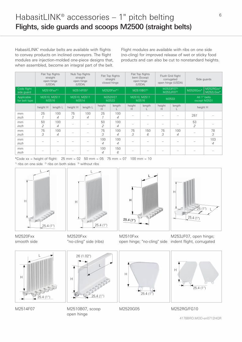
HabasitLINK® modular belts are available with flights to convey products on inclined conveyors. The flight modules are injection-molded one-piece designs that, when assembled, become an integral part of the belt.
Flight modules are available with ribs on one side (no-cling) for improved release of wet or sticky food products and can also be cut to nonstandard heights.
L
H
25.4 (1")
L
H
25.4 (1")
25.4 (1")
L
H
H
25.4 (1")
L25 (1")
Flat Top flights straight
open hinge (USDA)
Nub Top flights straight
open hinge (USDA)
Flat Top flights straight
closed hinge
Flat Top flights bent (Scoop)open hinge
(USDA)
Flush Grid flight corrugated
open hinge (USDA)Side guards
Code flight side guard
M2510Fxx*1) M2514F052) M2520Fxx*1) M2510B073) M2533F073) M253JF073) M2520Gxx*
M252RGxx*M252LGxx*
Applicablefor belt type
M2510, M2511M2516
M2510, M2511M2514
M2520/27M2533
M2510, M2511M2516
M2533All 1" belts
except M2531
height H length L height H length Lheight
Hlength
Lheight
Hlength
Lheight
Hlength
Lheight H
mminch
251
1004
753
1004
251
1004
– – – – 281 –
mminch
502
1004
– –502
1004
– – – –532
–
mminch
753
1004
– –753
1004
753
1506
753
1004
–783
mminch
– – – –1004
1004
– – – – –1034
mminch
– – – –1004
1506
– – – – – –
*Code xx = height of flight: 25 mm = 02 50 mm = 05 75 mm = 07 100 mm = 101) ribs on one side 2) ribs on both sides 3) without ribs
M2520Fxx smooth side
M2520Fxx"no-cling" side (ribs)
M2510Fxx open hinge; "no-cling" side
M253JF07, open hinge; indent flight, corrugated
M2510B07, scoopopen hinge
M2520G05 M252RG/FG10
H
H
L
26 (1.02")
M2514F07
H
L
H
L
25.4 (1“)
25.4 (1“)
25.4 (1“)
H
25.4 (1“)

7
4178BRO.MOD-en0712HQR
HabasitLINK® accessories – 1" pitch beltingFlights and side guards M2500 (straight belts)
Indents (E)The flight indent E is the distance between the edge of the belt and the edge of the flight, and F is the distance between belt edge and side guard. It is required for adequate support of the belt on its return way and hold-down during back bending applications (elevators). On short conveyors or with special support structure, the flights may also be applied over the full belt width (E = 0). For the Flush Grid, flight edge modules with indents are available (fixed indent see illustration).
Notch (N)The notch N is a gap in each row of flights, longitudinally aligned to allow the support of belts wider than 600 mm (24") on its return way or in back-bending applications. The notch width (N) and the distance M from the belt edge is a multiple of the link increment 16.67 mm (0.66"). For M2500 series the minimum notch width is 33.3 mm (1.31"). wear strip
transp.side
M
F
belt
N
returnway
transport side
return way
wear strip
belt
wear strip
belt

4178BRO.MOD-en0712HQR
8HabasitLINK® accessories – 1" pitch beltingFlights and side guards M2500 (straight belts)
Installation of flights and side guards; indents (For radius belts please refer to the specific data sheets.)The side guards are usually installed with a gap (G) between the side guards and the flights. It is also possible to install the side guards with a minimum gap
between flight and side guard of approx. 2 mm (0.08"). There is a certain risk for rubbing and abrasion between the flights and the side guards. The distance E1 between the side guards and the hold-down- and support shoes/wear strips should not be smaller than 5 mm (0.2").
n x L
E
b0
F
F
mid + edge modules
25 (1") 25 (1")0b
M2510 with flights M2510F05 and side guards M2520G05 (top view)
Flush Grid flight M2533F07 + M253JF07
M2510 with flights M2510F05 and side guards M2520G05 (bottom view)
Possible flight indents E (not for M2533F05 edge flight)
Flight onlyFlight + side guard
with gap (G ~8 mm (0.3“)Flight + side guard
without gap (G ~2 mm (0.08“)
E E F E F
mm inch mm inch mm inch mm inch mm inch
Flight over full belt width 0 0 – – – – – – – –
Module cutting necessary 33 1.3 33 1.3 16 0.65 33 1.3 25 1
Standard, no module cutting 50 2 50 2 33 1.3 50 2 41 1.6
Module cutting necessary 66 2.6 66 2.6 50 2 66 2.6 58 2.3
Module cutting necessary 83 3.2 83 3.2 66 2.6 83 3.2 75 3
Standard, no module cutting 100 4 100 4 83 3.2 100 4 93 3.7
9
4178BRO.MOD-en0712HQR
HabasitLINK® accessories – 1" pitch beltingHold-down devices for M2500 (straight belts)
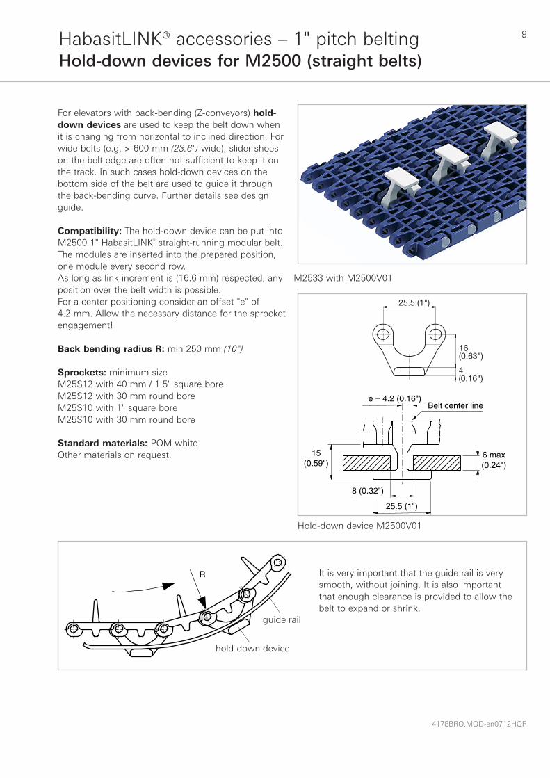
For elevators with back-bending (Z-conveyors) hold-down devices are used to keep the belt down when it is changing from horizontal to inclined direction. For wide belts (e.g. > 600 mm (23.6") wide), slider shoes on the belt edge are often not sufficient to keep it on the track. In such cases hold-down devices on the bottom side of the belt are used to guide it through the back-bending curve. Further details see design guide.
Compatibility: The hold-down device can be put into M2500 1" HabasitLINK® straight-running modular belt. The modules are inserted into the prepared position, one module every second row. As long as link increment is (16.6 mm) respected, any position over the belt width is possible. For a center positioning consider an offset "e" of 4.2 mm. Allow the necessary distance for the sprocket engagement!
Back bending radius R: min 250 mm (10")
Sprockets: minimum sizeM25S12 with 40 mm / 1.5" square boreM25S12 with 30 mm round boreM25S10 with 1" square boreM25S10 with 30 mm round bore
Standard materials: POM whiteOther materials on request.
M2533 with M2500V01
15(0.59")
8 (0.32")
e = 4.2 (0.16")Belt center line
25.5 (1")
6 max(0.24")
R
guide rail
hold down device
It is very important that the guide rail is very smooth, without joining. It is also important that enough clearance is provided to allow the belt to expand or shrink.
Hold-down device M2500V01
25.5 (1")
16 (0.63")
4 (0.16")
hold-down device
guide rail
4178BRO.MOD-en0712HQR
10HabasitLINK® accessories – 1" pitch beltingCombs for M2531
X3 X2
comb
K
X4
X4
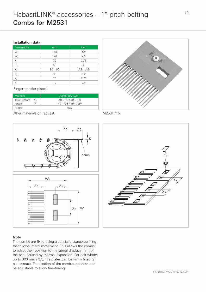
NoteThe combs are fixed using a special distance bushing that allows lateral movement. This allows the combs to adapt their position to the lateral displacement of the belt, caused by thermal expansion. For belt widths up to 300 mm (12"), the plates can be firmly fixed (2 plates max). The fixation of the comb support should be adjustable to allow fine-tuning.
Installation dataDimensions mm inch
W 148 5.8
WL 170 7.5
X1 70 2.75
X2 50 2
X3 80 – 90 3.2 – 3.5
X4 80 3.2
X5 70 2.75
K 10 0.4
(Finger transfer plates)
Material Acetal dry (wet)
Temperature °Crange °F
-40 – 90 (-40 – 60)-40 –195 (-40 –140)
Color grey
Other materials on request. M2531C15

11
4178BRO.MOD-en0712HQR
HabasitLINK® accessories – 1" pitch beltingFlights, side guards and lane dividers M2540
M2540 with middle and edge flights M2540 with side guards and lane divider
Flights are available in 50 mm (2") height, side guards and lane dividers in 25 mm (1") height, see illustrations below. Flights are available with ribs on one side for
better release of wet or sticky food products (no-cling). They can be cut to specific width and height if required. The collapse factor remains unchanged.
Middle flightM2540F05
Standard range of belt widths b0 for belts with flights
25.6 (1")
100(4")
50(2")
25.6 (1")
50(2")
25 (1") L
25(1")
28 (1.1")
11(0.4")
Real belt widths are in most cases 0.1% to 0.3% smaller.
mm 200 300 400 500 600 700 800 900 1000 1100 1200 1300 1400 1500 etc.
inch (nom.) 8 12 16 20 24 28 32 36 40 44 48 52 56 60 etc.
Lane dividerM2540W20
25(1")
Edge flightM254RF05 (right side)M254LF05 (left side)
Clip-on side guardsM254RG02 (right side)M254LG02 (left side)
4178BRO.MOD-en0712HQR
12HabasitLINK® accessories – 1" pitch beltingFlights, side guards and lane dividers M2540
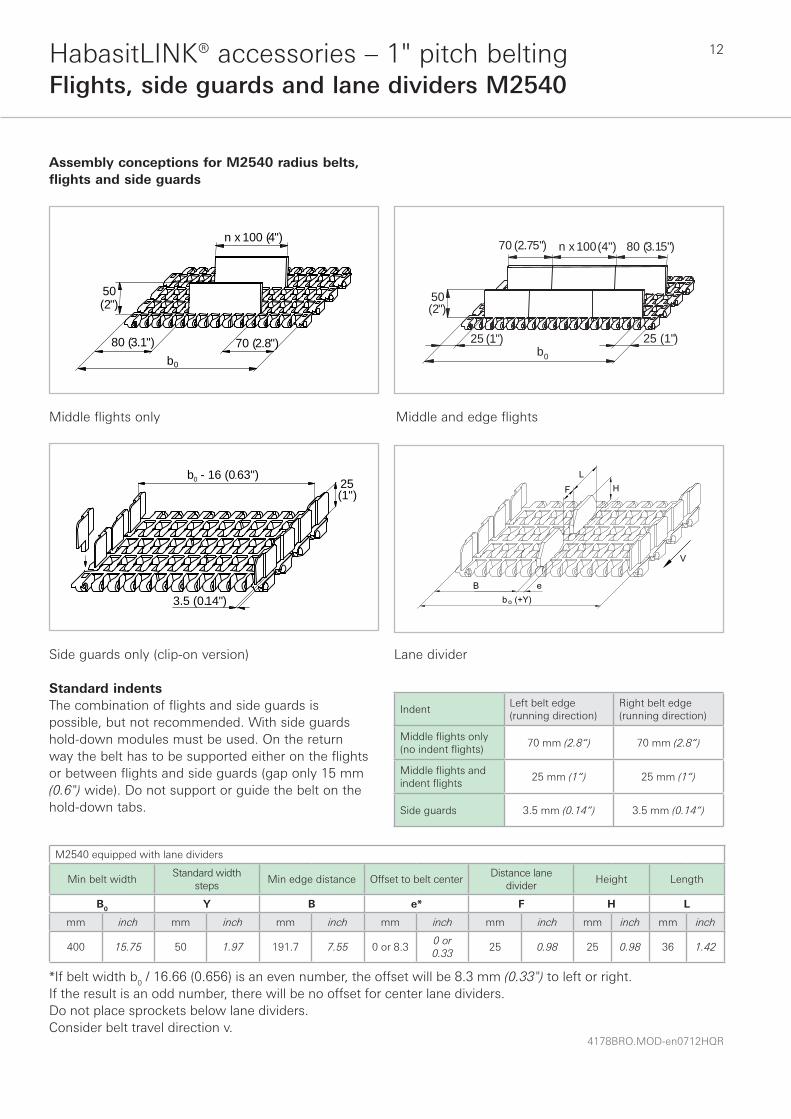
Assembly conceptions for M2540 radius belts, flights and side guards
Middle flights only Middle and edge flights
25 (1")25 (1")
50(2")
n x 100 (4")70 (2.75") 80 (3.15")
b0
80 (3.1")
b
n x 100 (4")
70 (2.8")
50(2")
0
25(1")
3.5 (0.14")
b - 16 (0.63")0
Side guards only (clip-on version)
Standard indentsThe combination of flights and side guards is possible, but not recommended. With side guards hold-down modules must be used. On the return way the belt has to be supported either on the flights or between flights and side guards (gap only 15 mm (0.6") wide). Do not support or guide the belt on the hold-down tabs.
Lane divider
IndentLeft belt edge(running direction)
Right belt edge(running direction)
Middle fl ights only (no indent fl ights)
70 mm (2.8“) 70 mm (2.8“)
Middle fl ights and indent fl ights
25 mm (1“) 25 mm (1“)
Side guards 3.5 mm (0.14“) 3.5 mm (0.14“)
M2540 equipped with lane dividers
Min belt widthStandard width
stepsMin edge distance Offset to belt center
Distance lane divider
Height Length
B0 Y B e* F H L
mm inch mm inch mm inch mm inch mm inch mm inch mm inch
400 15.75 50 1.97 191.7 7.55 0 or 8.30 or 0.33
25 0.98 25 0.98 36 1.42
*If belt width b0 / 16.66 (0.656) is an even number, the offset will be 8.3 mm (0.33") to left or right.If the result is an odd number, there will be no offset for center lane dividers. Do not place sprockets below lane dividers.Consider belt travel direction v.

13
4178BRO.MOD-en0712HQR
HabasitLINK® accessories – 1" pitch beltingHold-down tabs for M2540
To avoid the belt flipping over or slipping off the inner guide rail in the curve, hold-down guides are normally used. They are, however, not suitable if the conveyed goods are larger than the belt width or if side transfer over the belt edge is required. For these cases special modules equipped with hold-down tabs (hook modules) are available for both belt edges.
Hold-down edge modules M2540Hxx* and M2540 MTWHold-down tabs are used for all applications where the products must be able to move over the belt edge. The use of hold-down modules is also mandatory when applying side guards.
8.5 (0.33") 22 (0.86")
9 (0.35") 12.6 (0.5")
11 (0.43")
27.5 (1.1")
M2540Hxx M2540 MTW
M2540Hxx M2540 MTW
InstallationMake sure to keep clearance between guides, sprockets and hold-down tabs. They are meant to act as lift-off safety devices and not as guides! They will, if in contact with the guides, wear off quickly and may increase the tension in the belt.For these reasons the conveyor needs to be designed with the appropriate accuracy.Minimum belt width 150 mm (6") (2 sprockets) for use of hold-down edge modules and 250 mm for hold-down middle modules.

4178BRO.MOD-en0712HQR
14HabasitLINK® accessories – 1" pitch beltingHold-down device for M2540
Hold-down middle module (M2540V00)For elevators with back bending (Z-conveyors) hold-down devices are needed to keep the belt down when it is changing from horizontal to inclined direction. For wide belts (e.g. > 600 mm (23.5") wide) slider shoes on the belt edge are often not sufficient to keep it on the track. In such cases hold-down devices on the bottom side of the belt are used every second row to guide it through the back-bending curve. For belt width 300 mm + n * 100 mm the hook is placed in the belt center. For belt width 250 mm + n * 100 mm the hook has an offset of 25 mm left or right to the belt center. Please see table below.
Belt widthOffset
eRunning direction
ARunning direction
B
300 0 – –
350 25 to the left to the right
400 0 – –
450 25 to the left to the right
500 0 – –
550 25 to the left to the right
600 0 – –
650 25 to the left to the right
700 0 – –
750 25 to the left to the right
800 0 – –
850 25 to the left to the right
900 0 – –
Sprocket sizesThe combination sprocket/shaft size has to be selected in such a way to avoid collision of the hold-down tabs with the shaft. Minimum sprocket sizes: M25S1002Q, M25S1030R, M25S1240Q.
NoteThe hold-down device is not recommended to be used for radial guidance. They can be worn away quickly. Also, they should not be used to hang-up the belt on the return path.Further design indications see Design Guide Radius Belts and Slider Support Systems.
* Available edge module length same as with standard edge module
M2540V10
M2540V10

15
4178BRO.MOD-en0712HQR
HabasitLINK® accessories – 1-1/2" pitch beltingFlights, side guards and lane dividers M3840
M3840 with flights M3840 with side guards and lane dividers
Flights are available in 100 mm (4") height, clip-on side guards in 50 mm (2") height, see illustrations below. Flights are available with ribs on one side for better
release of wet or sticky food products (no-cling). They can be cut to specific width and height if required. The collapse factor remains unchanged.
Middle flightM3840F10
38.2 (1.5")
100(4")
100(4")
38.2 (1.5")
100(4")
25 (1")
L
50(2")
43 (1.7")
17.6(0.7")
Standard range of belt widths b0 for belts with flights
Real belt widths are in most cases 0.1% to 0.3% smaller.
mm 200 300 400 500 600 700 800 900 1000 1100 1200 1300 1400 1500 etc.
inch (nom.) 8 12 16 20 24 28 32 36 40 44 48 52 56 60 etc.
Lane dividerM3840W02
Edge flightM384RF10 (right side)M384LF10 (left side)The total length L of the right and left type add to 200 mm (8")
Side guardsM384RG05 (right side)M384LG05 (left side)Left and right version can be put on the opposite edge (no functional problems) but they cannot be mixed.
25(1")

4178BRO.MOD-en0712HQR
16HabasitLINK® accessories – 1-1/2" pitch beltingFlights, side guards and lane dividers M3840
Assembly conceptions for M3840 radius belts, flights and side guards
Middle flights only Middle and edge flights
25 (1")
b0
25 (1")
100(4")
n x 100 (4")70 (2.75") 80 (3.15")n x 100 (4")
80 (3.1")b0
70 (2. 8")
100(4")
50(2")
b - 24 (0.94")0
5 (0.2")
Side guards only (clip-on version)
Standard indentsThe combination of flights and side guards is possible but not recommended. With side guards, hold-down modules must be used. On the return way the belt has to be supported either on the flights or between flights and side guards (gap only 15 mm (0.6") wide). Do not support or guide the belt on the hold-down tabs.
IndentLeft belt edge(running direction)
Right belt edge(running direction)
Middle fl ights only (no indent fl ights)
70 mm (2.8“) 70 mm (2.8“)
Middle fl ights and indent fl ights
25 mm (1“) 25 mm (1“)
Side guards 3.5 mm (0.14“) 3.5 mm (0.14“)
Lane divider
M2544 equipped with lane dividers
Min belt widthStandard width
stepsMin edge distance Offset to belt center
Distance lane divider
Height Length
B0 Y B e* F H L
mm inch mm inch mm inch mm inch mm inch mm inch mm inch
400 15.75 50 1.97 191.7 7.55 0 or 8.30 or 0.33
16 0.63 25 0.98 34.8 1.37
*If belt width b0 / 25 (0.98) is an even number, the offset will be 12.5 mm (0.5") to left or right.If the result is an odd number, there will be no offset for center lane dividers. Do not place sprockets below lane dividers.Consider belt travel direction v.

17
4178BRO.MOD-en0712HQR
HabasitLINK® accessories – 1-1/2" pitch beltingHold-down tabs for M3840
To avoid the belt flipping over or slipping off the inner guide rail in the curve, hold-down guides are normally used. They are, however, not suitable if the conveyed goods are larger than the belt width or if side transfer over the belt edge is required. For these cases special modules equipped with hold-down tabs (hook modules) are available for both belt edges.
Hold-down modules (M3840H)Hold-down tabs are used for all applications where the products must be able to move over the belt edge. The use of hold-down modules is also mandatory when applying side guards.
InstallationMake sure to keep clearance between guides and hold-down tabs. They are meant to act as lift-off safety devices and not as guides! They will, if in contact with the guides, wear off quickly and may increase the tension in the belt.For these reasons the conveyor needs to be designed with the appropriate accuracy. Minimum belt width 175 mm (7") (2 sprockets).
Sprocket sizesThe combination sprocket/shaft size has to be selected in such a way to avoid collision of the hold-down tabs with the shaft. Minimum sprocket sizes: M38S1240Q, M38S1260Q.
NoteThe hold-down tabs are not recommended to be used for radial guidance. They can be worn away too quickly. They should not be used to hang up the belt on its return way.Further design indications see Design Guide Radius Belts and Slider Support Systems.
10 ( 0.39")
10 ( 0.39")14.5
(0.57")
17.2 ( 0.68 ")
6 (0.24 ")
18(0.71")

4178BRO.MOD-en0712HQR
18
M3843 with side guards
HabasitLINK® accessories – 1-1/2" pitch beltingSide guards M3843
Side guards are available in 50 mm height only.
15 (0.59")
b - 44 (1.73")050(2")
The snap-on side guards for M3843 cannot be used in combination with snap-on hold-down tabs (hooks or side tabs). To avoid the belt in the curve to flip over or slip off the inner guide rail, hold-down guides can be applied.

19
4178BRO.MOD-en0712HQR
HabasitLINK® accessories – 1-1/2" pitch beltingHold-down tabs and side tabs for M3843
To avoid the belt flipping over or slipping off the inner guide rail in the curve, hold-down guides are normally used. They are, however, not suitable if the conveyed goods are larger than the belt width or if side transfer over the belt edge is required. For these cases special modules equipped with hold-down tabs (hook modules) or side tabs are available for both belt edges.
Hold-down modules (M3843H00)Hold-down tabs are used for all applications where the products must be able to move over the belt edge.
Side tabs (M3843V00)Side tabs can be used instead of hold-down tabs for all applications where the products must be able to move over the belt edge.
InstallationBoth hold-down tabs and side tabs are snapped into the square hole provided at the outermost link of the edge modules. If ordered accordingly, M3843 belts are already furnished with these hold-down tabs when delivered.When installing on the conveyor frame, make sure to keep clearance between guides and tabs. They are meant to act as lift-off safety devices and not as guides! They will, if in contact with the guides, wear off quickly and may increase the tension in the belt.For these reasons the conveyor needs to be designed with the appropriate accuracy. Minimum belt width 175 mm (7") (2 sprockets).
Sprocket sizesThe combination sprocket/shaft size has to be selected in such a way to avoid collision of the hold-down tabs with the shaft. Minimum sprocket sizes: M38S1240Q, M38S1260Q.
NoteThe hold-down tabs are not recommended to be used for radial guidance. They can be worn away too quickly. Neither hold-down tabs nor side tabs should be used to hang up the belt on its return way.Further design indications see Design Guide Radius Belts and Slider Support Systems.
M3843H00
M3843V00
M3843H00
M3843V00
4178BRO.MOD-en0712HQR
20HabasitLINK® accessories – 2" pitch beltingFlights and side guards M5000
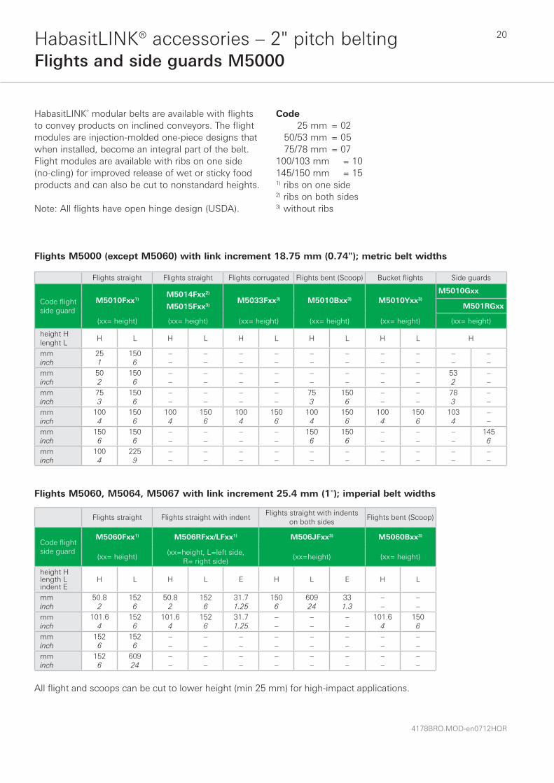
HabasitLINK® modular belts are available with flights to convey products on inclined conveyors. The flight modules are injection-molded one-piece designs that when installed, become an integral part of the belt. Flight modules are available with ribs on one side (no-cling) for improved release of wet or sticky food products and can also be cut to nonstandard heights.
Flights M5000 (except M5060) with link increment 18.75 mm (0.74"); metric belt widths
Flights straight Flights straight Flights corrugated Flights bent (Scoop) Bucket fl ights Side guards
Code fl ight side guard
M5010Fxx1)M5014Fxx2)
M5015Fxx3)M5033Fxx3) M5010Bxx3) M5010Yxx3)
M5010Gxx
M501RGxx
(xx= height) (xx= height) (xx= height) (xx= height) (xx= height) (xx= height)
height Hlenght L
H L H L H L H L H L H
mminch
251
1506
––
––
––
––
––
––
––
––
––
––
mminch
502
1506
––
––
––
––
––
––
––
––
532
––
mminch
753
1506
––
––
––
––
753
1506
––
––
783
––
mminch
1004
1506
1004
1506
1004
1506
1004
1506
1004
1506
1034
––
mminch
1506
1506
––
––
––
––
1506
1506
––
––
––
1456
mminch
1004
2259
––
––
––
––
––
––
––
––
––
––
Flights M5060, M5064, M5067 with link increment 25.4 mm (1"); imperial belt widths
Flights straight Flights straight with indentFlights straight with indents
on both sidesFlights bent (Scoop)
Code fl ight side guard
M5060Fxx1) M506RFxx/LFxx1) M506JFxx3) M5060Bxx3)
(xx= height)(xx=height, L=left side,
R= right side)(xx=height) (xx= height)
height Hlength Lindent E
H L H L E H L E H L
mminch
50.82
1526
50.82
1526
31.71.25
1506
60924
331.3
––
––
mminch
101.64
1526
101.64
1526
31.71.25
––
––
––
101.64
1506
mminch
1526
1526
––
––
––
––
––
––
––
––
mminch
1526
60924
––
––
––
––
––
––
––
––
All flight and scoops can be cut to lower height (min 25 mm) for high-impact applications.
Note: All flights have open hinge design (USDA).
Code 25 mm = 02 50/53 mm = 05 75/78 mm = 07 100/103 mm = 10 145/150 mm = 151) ribs on one side2) ribs on both sides3) without ribs

21
4178BRO.MOD-en0712HQR
L
H
50.8 (2")
L
H
50.8 (2")
H
50.8 (2")
L
H
50.8 (2")
L
H
50.8 (2")
54 (2.13")
HabasitLINK® accessories – 2" pitch beltingFlights and side guards M5000
M5010Fxx smooth side M5010Fxx “no-cling” side M5010Gxx
M5033F10 M5010Bxx
M501RGxx / LG
M5010Y10 M5014F10
M5015F10 M5060Fxx M506RFxx indent flight M5060B10
H
H
L
L
H
H
L
H
L
H
L
54 (2.13")
M506JF15
H
L
33 (1.3)
L
50.8 (2")
50.8 (2") 50.8 (2")
50.8 (2")
50.8 (2")50.8 (2")50.8 (2")
33 (1.3)
50.8 (2")
H
L
50.8 (2")31.7 (1.25")
4178BRO.MOD-en0712HQR
22HabasitLINK® accessories – 2" pitch beltingFlights and side guards M5000
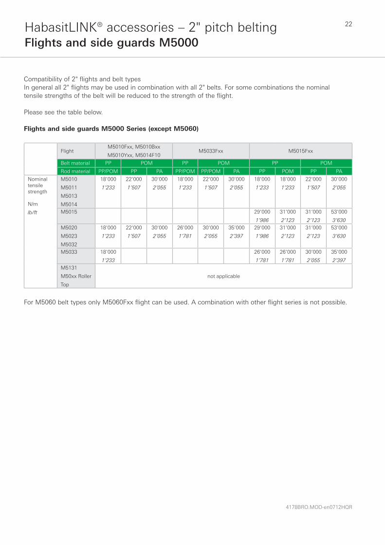
Compatibility of 2" flights and belt typesIn general all 2" flights may be used in combination with all 2" belts. For some combinations the nominal tensile strengths of the belt will be reduced to the strength of the flight.
Please see the table below.
Flights and side guards M5000 Series (except M5060)
FlightM5010Fxx, M5010Bxx
M5010Yxx, M5014F10M5033Fxx M5015Fxx
Belt material PP POM PP POM PP POM
Rod material PP/POM PP PA PP/POM PP/POM PA PP POM PP PA
Nominal tensile strength
N/m
lb/ft
M5010
M5011
M5013
M5014
18’000
1’233
22’000
1’507
30’000
2’055
18’000
1’233
22’000
1’507
30’000
2’055
18’000
1’233
18’000
1’233
22’000
1’507
30’000
2’055
M5015 29’000
1’986
31’000
2’123
31’000
2’123
53’000
3’630M5020
M5023
M5032
18’000
1’233
22’000
1’507
30’000
2’055
26’000
1’781
30’000
2’055
35’000
2’397
29’000
1’986
31’000
2’123
31’000
2’123
53’000
3’630
M5033 18’000
1’233
26’000
1’781
26’000
1’781
30’000
2’055
35’000
2’397M5131
M50xx Roller
Top
not applicable
For M5060 belt types only M5060Fxx flight can be used. A combination with other flight series is not possible.

23
4178BRO.MOD-en0712HQR
HabasitLINK® accessories – 2" pitch beltingFlights and side guards M5000
Indents (E)The flight indent E is the distance between the edge of the belt and the edge of the flight, and F is the distance between belt edge and side guard. It is required for adequate support of the belt on its return way and hold-down during back-bending applications (elevators). On short conveyors or with special support structure, the flights may also be applied over the full belt width (E = 0).
Notch (N)The notch N is a gap in each row of flights, longitudinally aligned to allow the support of belts wider than 600 mm (24") on their return way or in back-bending applications. The notch width (N) and the distance (M) from the belt edge is a multiple of the link increment 18.75 mm (0.74"). or 25.4 mm (1") for M5060 series. For metric M5000 series the minimum notch width is 37.5 mm (1.48") and for M5060 50.8 mm (2").
wear strip
transp.side
M
F
belt
N
returnway

4178BRO.MOD-en0712HQR
24HabasitLINK® accessories – 2" pitch beltingFlights and side guards M5000
n x L
EEb0
Installation of flights and side guards; indents The side guards are usually installed with a gap (G) between the side guards and the flights. It is also possible to install the side guards with a minimum gap between flight and side guards of approx. 2 mm
(0.08"). There is a certain risk for rubbing and abrasion between the flights and the side guards. The distance E1 between the side guards and the hold-down and support shoes/wear strips should not be smaller than 5 mm (0.2").
b0 FF
Possible fl ight indents E
Flight onlyFlight + side guard
with gap (G ~ 8 mm (0.31“))Flight + side guard
without gap (G ~2 mm (0.08“))
E E F E F
M5000 except M5060 mm inch mm inch mm inch mm inch mm inch
Flight over full belt width 0 0 – – – – – – – –
Module cutting necessary 37.5 1.47 37.5 1.47 18 0.47 37.5 1.47 28 1.1
Module cutting necessary 56 2.2 56 2.2 37 1.47 56 2.2 46 1.83
Standard, no module cutting 75 3 75 3 56 2.2 75 3 66 2.6
Module cutting necessary 112 4.4 112 4.4 93 3.7 112 4.4 103 4.1
Module cutting necessary 131 5.2 131 5.2 112 4.4 131 5.2 122 4.8
M5060
Flight over full belt width 0 0 – – – – – – – –
Module cutting necessary 50.8 2 50.8 2 34.2 1.35 – – – –
Module cutting necessary 76.2 3 76.2 3 59.6 2.35 – – – –
Standard, no module cutting 101.6 4 101.6 4 85 3.35 – – – –
Module cutting necessary 127 5 127 5 110.4 4.35 – – – –
Module cutting necessary 152.4 6 152.4 6 135.8 5.35 – – – –
Flight with molded indent 33 1.3 – – – – – – – –

25
4178BRO.MOD-en0712HQR
HabasitLINK® accessories – 2" pitch beltingHold-down device for M5000
For elevators with back-bending (Z-conveyors) hold-down devices are used to keep the belt down when it is changing from horizontal to inclined direction. For wide belts (e.g. > 800 mm (31.5") wide) slider shoes on the belt edge are often not sufficient to keep it on the track. In such cases hold-down devices on the bottom side of the belt are used to guide it through the back-bending curve.
Compatibility: The hold-down device can be put into any M5000 HabasitLINK® modular belt. The modules are inserted into the prepared position, one module every second row. As long as link steps are respected, any position over the belt width is possible.
M5000V01For a center positioning consider an offset “e” of 4.8 mm. Allow the necessary distance for the sprocket engagement!
Back-bending radius R: min 250 mm (10")Sprockets: minimum size M50S0840Q (8 teeth) and M50S1060Q (10 teeth)Standard materials: POM white, other materials possible on requestCompatible belts series: M5010, M5020, M5030
M5060V05The tab module M5060V05 is designed as 2" mid module to be brick-layed as a regular module. The length of two link indents give stability to the tab. This module cannot be used as edge module.
Back-bending radius R: min 250 mm (10")Sprockets: minimum size 8 teeth (M50S08)Standard materials: POM white, other materials possible on requestCompatible belts series: only M5060
R
guide rail
hold down device
It is very important that the guide rail is very smooth, without joining. It is also important that enough clearance is provided to allow the belt to expand or shrink.
50.8 (2" )
22(0.86")
8(0.3")
e = 4.8 (0.19")
Belt center line
22(0.86")
30 (1.2")
12 (0.5")
10 max (0.4")
hold-down device
guide rail

4178BRO.MOD-en0712HQR
26HabasitLINK® accessories – 2" pitch beltingCombs for M5131
Long-tooth comb M5131C15Installation data
Dimensions mm inch
W 151 5.9
WL 190 7.5
X1 76 3.0
X2 50 2.0
X3 100 – 110 3.9 – 4.3
X4 76 3.0
X5 90 3.5
K 12 0.5
Y dp/2+4 dp/2+0.2
Short-tooth comb M5131C16Installation data
Dimensions mm inch
W 151 5.9
WL 165 6.5
X1 76 3.0
X2 50 2.0
X3 100 3.9
X4 76 3.0
X5 40 1.6
K 12 0.5
Y dp/2+4 dp/2+0.2
Material dataMaterial Acetal dry (wet)
Temperature °Crange °F
-40 – 90 (-40 – 60)-40 –195 ( -40 –140)
Color grey
Other materials on request.
NoteThe combs are fixed using a special distance bushing that allows lateral movement. This allows the combs to adapt their position to the lateral displacement of the belt, caused by thermal expansion. For belt widths up to 300 mm (12"), the plates can be firmly fixed (2 plates max). The fixation of the comb support should be adjustable to allow fine-tuning.
pD
X 3
Y
comb
K
X 2

27
4178BRO.MOD-en0712HQR
HabasitLINK® accessories – 2" pitch beltingSide guards and lane dividers M5200
M5290 with side guards and lane dividers
Side guardM5290G02
Lane dividerM5290W02
M5290/93 equipped with lane dividers
Min. belt widthStandard width
stepsMin. edge distance Offset to belt center
Distance lane divider
Height Length
B0 Y B e* F H L
mm inch mm inch mm inch mm inch mm inch mm inch mm inch
508 20 25.4 1.0 127 5.00 or 12.7
0 or 0.5 22 0.87 25 0.98 29 1.14
*If belt width b0 / 25.4 (1) is an even number, the offset will be 12.7 mm (0.5") to left or right.If the result is an odd number, there will be no offset for center lane dividers. Do not place sprockets below lane dividers.
Side guards and lane dividers are used to separate products on one belt. Both modules are clip-on versions.
Assembly conceptions for M5290/93 radius belts, side guards and lane dividers
HH
4178BRO.MOD-en0712HQR
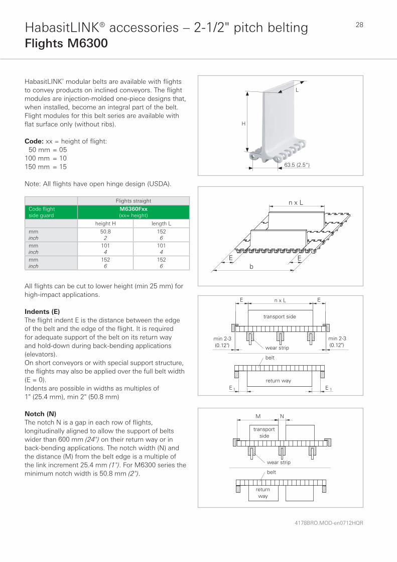
28HabasitLINK® accessories – 2-1/2" pitch beltingFlights M6300
HabasitLINK® modular belts are available with flights to convey products on inclined conveyors. The flight modules are injection-molded one-piece designs that, when installed, become an integral part of the belt. Flight modules for this belt series are available with flat surface only (without ribs). Code: xx = height of flight: 50 mm = 05100 mm = 10150 mm = 15
Note: All flights have open hinge design (USDA).
Flights straight
Code fl ight side guard
M6360Fxx(xx= height)
height H length L
mminch
50.82
1526
mminch
1014
1014
mminch
1526
1526
All flights can be cut to lower height (min 25 mm) for high-impact applications.
Indents (E)The flight indent E is the distance between the edge of the belt and the edge of the flight. It is required for adequate support of the belt on its return way and hold-down during back-bending applications (elevators). On short conveyors or with special support structure, the flights may also be applied over the full belt width (E = 0).Indents are possible in widths as multiples of 1" (25.4 mm), min 2" (50.8 mm)
Notch (N)The notch N is a gap in each row of flights, longitudinally aligned to allow the support of belts wider than 600 mm (24") on their return way or in back-bending applications. The notch width (N) and the distance (M) from the belt edge is a multiple of the link increment 25.4 mm (1"). For M6300 series the minimum notch width is 50.8 mm (2").
H
L
63.5 (2.5“)

29
4178BRO.MOD-en0712HQR
HabasitLINK® accessories – 2-1/2“ pitch beltingSkid guard module and stopper module M6400
M6400 skid guard modules have been developed for longitudinal skid conveying applications to avoid move off from 100 mm wide belts.The admissible tensile strength is limited to 60,000 N/m (4,111 lbf/ft).
Tire stopper modules are developed to keep car tires on a defined position on a belt. The modules are an integral part of the entire belt.The admissible tensile strength is limited to 60,000 N/m (4,111 lbf/ft).
Skid guard moduleM6420XB1
Stopper moduleM6420S04

HeadquartersHabasit AG Römerstrasse 1CH-4153 Reinach, Switzerland Phone +41 61 715 15 15Fax +41 61 715 15 55E-mail [email protected] www.habasit.com
Registered trademarks Copyright Habasit AGSubject to alterationsPrinted in SwitzerlandPublication data: 4178BRO.MOD-en0712HQR
Austria Habasit GmbH, Wien Phone: +43 1 690 66www.habasit.at
BelgiumHabasit Belgium N.V., ZaventemPhone: +32 27 250 430www.habasit.be
CanadaHabasit Canada Ltd., OakvillePhone: +1 905 827 41 31www.habasit.ca
ChinaHabasit East Asia Ltd., Hong KongPhone: +85 221 450 150 www.habasit.com.hk
Habasit (Shanghai) Co. Ltd.ShanghaiPhone: +8621 5488 1228Phone: +8621 5488 1218www.habasit.com.hk
FranceHabasit France S.A.S., MulhousePhone: +33 389 338 903 www.habasit.fr
Germany Habasit GmbHEppertshausenPhone: +49 6071 969 0 www.habasit.de
IndiaHabasit-Iakoka Pvt. Ltd., CoimbatorePhone: +91 422 262 78 79www.habasitiakoka.com
ItalyHabasit Italiana SpACustomer Care:Phone: 199 199 333For int. calls: +39 0438 911 444 www.habasit.it
JapanHabasit Nippon Co. Ltd., YokohamaPhone: +81 454 760 371 www.habasit.co.jp
NetherlandsHabasit Netherlands BV, NijkerkPhone: +31 332 472 030 www.habasit.nl
New Zealand Habasit Australasia Ltd., Hornby Phone: +64 3348 5600 www.habasit.co.nz
NorwayHabasit Norge A/S, OsloPhone: +47 815 58 458www.habasit.no
PolandHabasit Polska Sp. zo.o.Dàbrowa Górnicza,Phone: +48 32639 02 40www.habasit.pl
RussiaOOO Habasit Ltd., St. PetersburgPhone: +7 812 600 40 80www.habasit.ru
SingaporeHabasit Far East Pte. Ltd., SingaporePhone: +65 686 255 66 www.habasit.com.sg
SpainHabasit Hispanica S.A.Barberà del VallèsPhone: +34 937 191 912 www.habasit.es
SwedenHabasit AB, HindasPhone: +46 30 122 600www.habasit.se
SwitzerlandHabasit GmbH, ReinachPhone: +41 61 577 51 00www.habasit.ch
TaiwanHabasit Rossi (Taiwan) Ltd.Taipei HsienPhone: +886 2 2267 0538www.habasit.com.tw
TurkeyHabasit Kayis San. Ve Tic. Ltd. Sti.Yenibosna - Bahcelievler - IstanbulPhone: +90 212 654 94 04www.habasit.com.tr
UkraineHabasit Ukraina, VinnicaPhone: +38 0432 58 47 35www.habasit.ua
United Kingdom and IrelandHabasit Rossi (UK) Ltd., Silsden Phone: +44 844 835 9555 www.habasitrossi.co.uk
USAHabasit America Conveyor belts, power transmission belts, gearmotors Suwanee, Georgia Phone: +1 800 458 6431 www.habasitamerica.com
Habasit America Seamless belts, timing belts Middletown, Connecticut Phone: +1 860 632 2211 www.habasitamerica.com
Rossi is one of Europe’s largest manufacturers of gear reducers, gearmotors, inverters, standard and brakemotors, and is a member of the Habasit Group.
Rossi S.p.A. Via Emilia Ovest 915/A41123 Modena – ItalyPhone: +39 059 33 02 [email protected]