haas-mill-programming-manual.pdf
TRANSCRIPT

8/20/2019 Haas-Mill-Programming-Manual.pdf
http://slidepdf.com/reader/full/haas-mill-programming-manualpdf 1/115

8/20/2019 Haas-Mill-Programming-Manual.pdf
http://slidepdf.com/reader/full/haas-mill-programming-manualpdf 2/115
8/20/2019 Haas-Mill-Programming-Manual.pdf
http://slidepdf.com/reader/full/haas-mill-programming-manualpdf 3/115

8/20/2019 Haas-Mill-Programming-Manual.pdf
http://slidepdf.com/reader/full/haas-mill-programming-manualpdf 4/115

8/20/2019 Haas-Mill-Programming-Manual.pdf
http://slidepdf.com/reader/full/haas-mill-programming-manualpdf 5/115

8/20/2019 Haas-Mill-Programming-Manual.pdf
http://slidepdf.com/reader/full/haas-mill-programming-manualpdf 6/115
8/20/2019 Haas-Mill-Programming-Manual.pdf
http://slidepdf.com/reader/full/haas-mill-programming-manualpdf 7/115

8/20/2019 Haas-Mill-Programming-Manual.pdf
http://slidepdf.com/reader/full/haas-mill-programming-manualpdf 8/115

8/20/2019 Haas-Mill-Programming-Manual.pdf
http://slidepdf.com/reader/full/haas-mill-programming-manualpdf 9/115

8/20/2019 Haas-Mill-Programming-Manual.pdf
http://slidepdf.com/reader/full/haas-mill-programming-manualpdf 10/115

8/20/2019 Haas-Mill-Programming-Manual.pdf
http://slidepdf.com/reader/full/haas-mill-programming-manualpdf 11/115

8/20/2019 Haas-Mill-Programming-Manual.pdf
http://slidepdf.com/reader/full/haas-mill-programming-manualpdf 12/115

8/20/2019 Haas-Mill-Programming-Manual.pdf
http://slidepdf.com/reader/full/haas-mill-programming-manualpdf 13/115

8/20/2019 Haas-Mill-Programming-Manual.pdf
http://slidepdf.com/reader/full/haas-mill-programming-manualpdf 14/115

8/20/2019 Haas-Mill-Programming-Manual.pdf
http://slidepdf.com/reader/full/haas-mill-programming-manualpdf 15/115

8/20/2019 Haas-Mill-Programming-Manual.pdf
http://slidepdf.com/reader/full/haas-mill-programming-manualpdf 16/115

8/20/2019 Haas-Mill-Programming-Manual.pdf
http://slidepdf.com/reader/full/haas-mill-programming-manualpdf 17/115

8/20/2019 Haas-Mill-Programming-Manual.pdf
http://slidepdf.com/reader/full/haas-mill-programming-manualpdf 18/115
8/20/2019 Haas-Mill-Programming-Manual.pdf
http://slidepdf.com/reader/full/haas-mill-programming-manualpdf 19/115

8/20/2019 Haas-Mill-Programming-Manual.pdf
http://slidepdf.com/reader/full/haas-mill-programming-manualpdf 20/115
8/20/2019 Haas-Mill-Programming-Manual.pdf
http://slidepdf.com/reader/full/haas-mill-programming-manualpdf 21/115
8/20/2019 Haas-Mill-Programming-Manual.pdf
http://slidepdf.com/reader/full/haas-mill-programming-manualpdf 22/115
8/20/2019 Haas-Mill-Programming-Manual.pdf
http://slidepdf.com/reader/full/haas-mill-programming-manualpdf 23/115

8/20/2019 Haas-Mill-Programming-Manual.pdf
http://slidepdf.com/reader/full/haas-mill-programming-manualpdf 24/115
8/20/2019 Haas-Mill-Programming-Manual.pdf
http://slidepdf.com/reader/full/haas-mill-programming-manualpdf 25/115

8/20/2019 Haas-Mill-Programming-Manual.pdf
http://slidepdf.com/reader/full/haas-mill-programming-manualpdf 26/115

8/20/2019 Haas-Mill-Programming-Manual.pdf
http://slidepdf.com/reader/full/haas-mill-programming-manualpdf 27/115

8/20/2019 Haas-Mill-Programming-Manual.pdf
http://slidepdf.com/reader/full/haas-mill-programming-manualpdf 28/115

8/20/2019 Haas-Mill-Programming-Manual.pdf
http://slidepdf.com/reader/full/haas-mill-programming-manualpdf 29/115

8/20/2019 Haas-Mill-Programming-Manual.pdf
http://slidepdf.com/reader/full/haas-mill-programming-manualpdf 30/115
8/20/2019 Haas-Mill-Programming-Manual.pdf
http://slidepdf.com/reader/full/haas-mill-programming-manualpdf 31/115

8/20/2019 Haas-Mill-Programming-Manual.pdf
http://slidepdf.com/reader/full/haas-mill-programming-manualpdf 32/115

8/20/2019 Haas-Mill-Programming-Manual.pdf
http://slidepdf.com/reader/full/haas-mill-programming-manualpdf 33/115

8/20/2019 Haas-Mill-Programming-Manual.pdf
http://slidepdf.com/reader/full/haas-mill-programming-manualpdf 34/115
Productivity Inc - Haas CNC Mill Programming Manual Page 32
Linear and Circular Tool Paths
Tool paths are the movements that we program once we have loaded our tool, turned our spindle on, andhave approached the part. It is the motion that we generate with a particular tool to generate the shapes
and sizes we need to complete our parts.
Objectives:
Upon completion of this unit, the student will:
1) Understand the major differences in G01 and G00.
2) Understand and apply the five criteria needed to produce an arc.
3) Understand the principles of programming and applications with and without cutter
compensation and the advantages and disadvantages of each.
4) Be capable of producing a tool path program, containing lines and arcs, with and without cuttercompensation.
5) Be capable of determining feeds and speeds given an SFM and cutting tool, and be capable ofdetermining feed rate given an RPM and chip load.
6) Be able to integrate a tool path into a part program.
7) Understand the rules governing the use of cutter compensation.
8) Have a basic understanding of the concept of arc in/arc out and some of its applications.

8/20/2019 Haas-Mill-Programming-Manual.pdf
http://slidepdf.com/reader/full/haas-mill-programming-manualpdf 35/115
Productivity Inc - Haas CNC Mill Programming Manual Page 33
Linear/Circular Movement Creating Tool Path
Rapid Position Commands
G00 Rapid Motion Positioning
X Optional X-axis motion commandY Optional Y-axis motion commandZ Optional Z-axis motion commandA Optional A-axis motion command
This G code is for rapid traverse of the axes of our machine. The human mind thinks point to point, and asin the example below, we will move from X-3.0 Y-1.0 to X2.25 Y1.25 and we want to think the machine willmove strait or as the crow flies . The code G00, means MOVE AS FAST AS POSSIBLE, which means moveall axis at full speed. Since all of the axis will move at the same speed, the machine will make a 45 degreemove till it achieves the position in one axis (Y in the example below) and finish the other till the point isachieved.
If we need to move in a strait line, the machine will only move in a strait line when told so, and that iswhat G01 is for.
8/20/2019 Haas-Mill-Programming-Manual.pdf
http://slidepdf.com/reader/full/haas-mill-programming-manualpdf 36/115
Productivity Inc - Haas CNC Mill Programming Manual Page 34
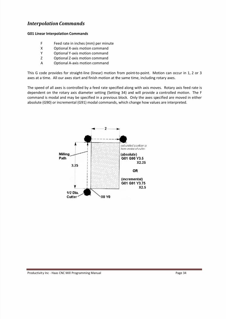
Interpolation Commands
G01 Linear Interpolation Commands
F Feed rate in inches (mm) per minuteX Optional X-axis motion commandY Optional Y-axis motion commandZ Optional Z-axis motion commandA Optional A-axis motion command
This G code provides for straight-line (linear) motion from point-to-point. Motion can occur in 1, 2 or 3axes at a time. All our axes start and finish motion at the same time, including rotary axes.
The speed of all axes is controlled by a feed rate specified along with axis moves. Rotary axis feed rate isdependent on the rotary axis diameter setting (Setting 34) and will provide a controlled motion. The Fcommand is modal and may be specified in a previous block. Only the axes specified are moved in eitherabsolute (G90) or incremental (G91) modal commands, which change how values are interpreted.
8/20/2019 Haas-Mill-Programming-Manual.pdf
http://slidepdf.com/reader/full/haas-mill-programming-manualpdf 37/115
Productivity Inc - Haas CNC Mill Programming Manual Page 35
Circular Interpolation (G02 and G03) Commands
G02 CW Circular Interpolation Motion
F Feed rate in inches (mm) per minuteI Optional distance along X-axis to center of circleJ Optional distance along Y-axis to center of circle
K Optional distance along Z-axis to center of circleR Optional radius of circleX Optional X-axis motion commandY Optional Y-axis motion commandZ Optional Z-axis motion commandA Optional A-axis motion command
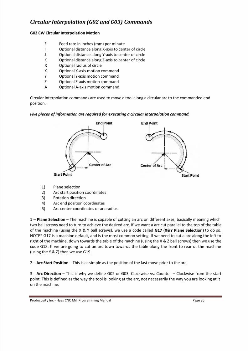
Circular interpolation commands are used to move a tool along a circular arc to the commanded endposition.
Five pieces of information are required for executing a circular interpolation command :
1) Plane selection2) Arc start position coordinates3) Rotation direction4) Arc end position coordinates5) Arc center coordinates or arc radius.
1 Plane Selection The machine is capable of cutting an arc on different axes, basically meaning whichtwo ball screws need to turn to achieve the desired arc. If we want a arc cut parallel to the top of the tableof the machine (using the X & Y ball screws), we use a code called G17 (X&Y Plane Selection) to do so.NOTE* G17 is a machine default, and is the most common setting. If we need to cut a arc along the left toright of the machine, down towards the table of the machine (using the X & Z ball screws) then we use the
code G18. If we are going to cut an arc town towards the table along the front to rear of the machine(using the Y & Z) then we use G19.
2 Arc Start Position This is as simple as the position of the last move prior to the arc.
3 - Arc Direction This is why we define G02 or G03, Clockwise vs. Counter Clockwise from the startpoint. This is defined as the way the tool is looking at the arc, not necessarily the way you are looking at iton the machine.

8/20/2019 Haas-Mill-Programming-Manual.pdf
http://slidepdf.com/reader/full/haas-mill-programming-manualpdf 38/115
Productivity Inc - Haas CNC Mill Programming Manual Page 36
4 Arc End Co-Ordinates This is where we want the arc to end. We define the end point of the arc ineither G90 or G91, and we can use up to 3 axis to do so.
5 Center of Arc Location I, J, and K method or R method
I,J,K are used to define the distance from our known Start Point of our arc to the center of the arc. I = theincremental distance in X, J = the incremental distance in Y, and in the case of G18 and G19, K = theincremental distance in Z. All of these values tell the machine our arc hinges on a point so far from thearc start point.
R method enables the machine to find the location on it s own. In our arc command line we define the endpoint, then tell the machine to maintain a certain radius between the points. The R method will work onarcs from 0 359.9999 degrees. If it is a full circle, we use I,J,K
Either system is valid. The R method arrived after machines were smart enough to calculate an arc.
G02 Circular Interpolation Clockwise Command
The circular interpolation contouring control uses the axis information contained in a block to move thetool in a CLOCKWISE arc of a circle up to 360 degrees.
The velocity at which the tool is moved is controlled by the feedrate (F) command.
All circles are defined and machined by programming three pieces of information to the control:
1) START POINT of the arc2) END POINT of the arc3) ARC CENTER distance from the start point
The START POINT is defined prior to the G02 line, usually by a G01 linear positioning move.
The END POINT is defined by the X and Y coordinates within the G02 line when in the G17 XY PLANE.
The ARC CENTER is defined in the G02 line by the I and J values, when in the G17-XY PLANE,or by aR value. Note the above will cut a .500 radius on the part.

8/20/2019 Haas-Mill-Programming-Manual.pdf
http://slidepdf.com/reader/full/haas-mill-programming-manualpdf 39/115
8/20/2019 Haas-Mill-Programming-Manual.pdf
http://slidepdf.com/reader/full/haas-mill-programming-manualpdf 40/115
Productivity Inc - Haas CNC Mill Programming Manual Page 38
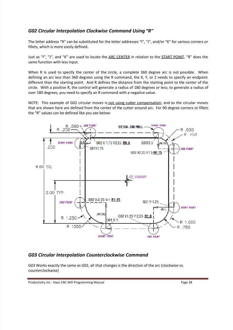
G02 Circular Interpolation Clockwise Command Using R
The letter address R can be substituted for the letter addresses I , J , and/or K for various corners orfillets, which is more easily defined.
Just as I , J , and K are used to locate the ARC CENTER in relation to the START POINT, R does thesame function with less input.
When R is used to specify the center of the circle, a complete 360 degree arc is not possible. Whendefining an arc less than 360 degrees using the R command, the X, Y, or Z needs to specify an endpointdifferent than the starting point. And R defines the distance from the starting point to the center of thecircle. With a positive R, the control will generate a radius of 180 degrees or less; to generate a radius ofover 180 degrees, you need to specify an R command with a negative value.
NOTE: This example of G02 circular moves is not using cutter compensation, and so the circular movesthat are shown here are defined from the center of the cutter around arc. For 90 degree corners or filletsthe R values can be defined like you see below:
G03 Circular Interpolation Counterclockwise Command
G03 Works exactly the same as G02, all that changes is the direction of the arc (clockwise vs.counterclockwise)

8/20/2019 Haas-Mill-Programming-Manual.pdf
http://slidepdf.com/reader/full/haas-mill-programming-manualpdf 41/115
Productivity Inc - Haas CNC Mill Programming Manual Page 39
Positive R vs. Negative R
The first R capable controls were able to use the R, but only up to 180 degrees. The reason being, is thatfor any two points in space, when a radius is defined, there are actually two paths that will use both pointsand that defined arc that are correct. One is less than 180 degrees, one is greater. We only could use thearcs less than 90 degrees. Eventually, we had enough computing power to tell the machine which one wewant. Examples are below.
The following line will cut an arc less than 180 degrees using an R positive :
G90 G54 G00 X-.25 Y-.25G01 Y1.5 F12.G02 X1.884 Y2.384 R1.25
To generate an arc of more than 180 degrees using a negative R minus :
G90 G54 G00 X-.25 Y-.25G01 Y1.5 F12G02 X1.884 Y.616 R-1.25

8/20/2019 Haas-Mill-Programming-Manual.pdf
http://slidepdf.com/reader/full/haas-mill-programming-manualpdf 42/115
Productivity Inc - Haas CNC Mill Programming Manual Page 40
8/20/2019 Haas-Mill-Programming-Manual.pdf
http://slidepdf.com/reader/full/haas-mill-programming-manualpdf 43/115
Productivity Inc - Haas CNC Mill Programming Manual Page 41
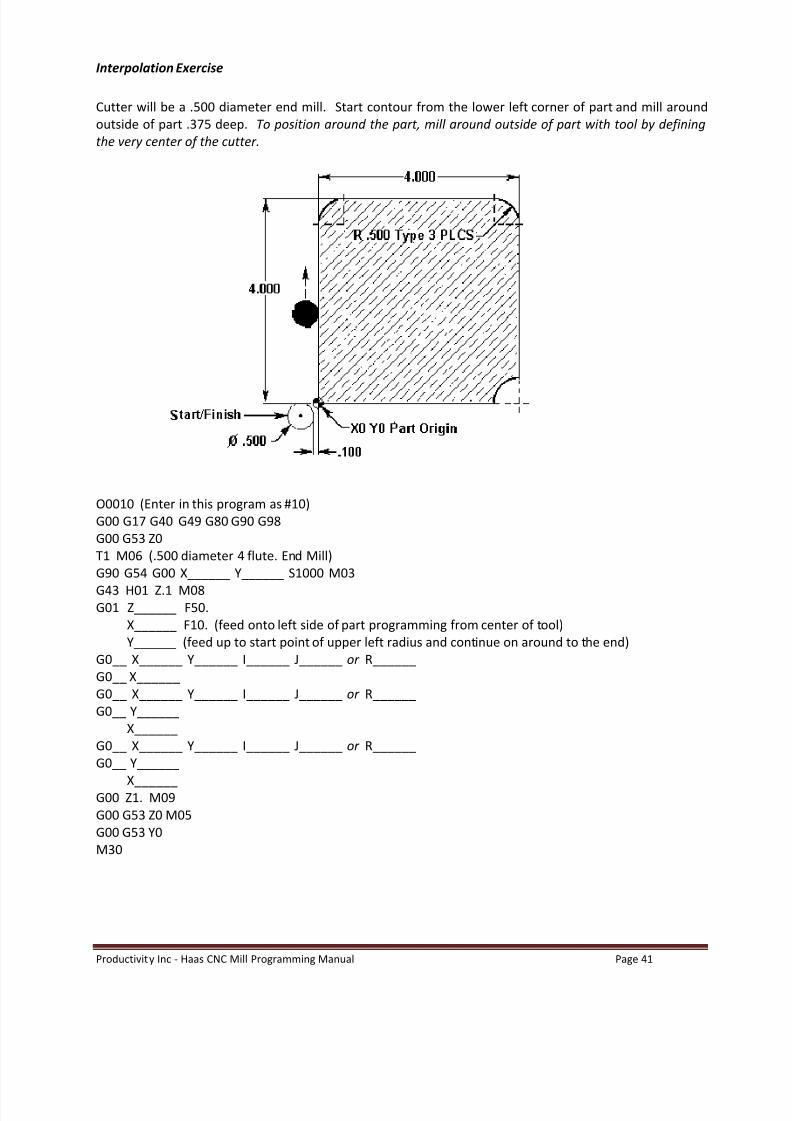
Interpolation Exercise
Cutter will be a .500 diameter end mill. Start contour from the lower left corner of part and mill aroundoutside of part .375 deep. To position around the part, mill around outside of part with tool by definingthe very center of the cutter.
O0010 (Enter in this program as #10)G00 G17 G40 G49 G80 G90 G98G00 G53 Z0T1 M06 (.500 diameter 4 flute. End Mill)G90 G54 G00 X______ Y______ S1000 M03
G43 H01 Z.1 M08G01 Z______ F50.
X______ F10. (feed onto left side of part programming from center of tool)Y______ (feed up to start point of upper left radius and continue on around to the end)
G0__ X______ Y______ I______ J______ or R______G0__ X______G0__ X______ Y______ I______ J______ or R______G0__ Y______
X______G0__ X______ Y______ I______ J______ or R______G0__ Y______
X______G00 Z1. M09G00 G53 Z0 M05G00 G53 Y0M30

8/20/2019 Haas-Mill-Programming-Manual.pdf
http://slidepdf.com/reader/full/haas-mill-programming-manualpdf 44/115
Productivity Inc - Haas CNC Mill Programming Manual Page 42
Cutter Compensation (G41, G42)
As you can see with the above examples, programming our contours can require a certain amount ofthinking and math to work with our tool diameters. The math isn t hard, as long as we have sharp cornersand even sized end mills and even sized parts. When we start running re-grind tooling, have special angelsor arcs, or any other no-typical variables on our part, programming becomes more difficult.
As time progressed, the machine computer controls became sophisticated enough to self-compensate forour tool diameters. We could tell the machine we had a .500 roughing tool and finish with another toolthat was .375 and still the same program. We just had to tell the machine our tool was of a different size.
We do this by using a feature called Cutter Compensation, or Cutter Comp. for short. With cutter comp weprogram the contour of our part, tell the machine what side of the profile to keep the tool on, and the tooldiameter.
Advantages of Cutter Compensation
1) The mathematical computations for determining a tool path are greatly simplified.
2) The part, and not the tool center, is programmed. Therefore, the same program can be usedfor a variety of different cutter diameters.
3) The same program path can be used for roughing, as well as finishing cuts, by using differentcutter offsets.
4) Inside, as well as outside, cuts can be performed.
Some Restrictions with Cutter Compensation
1) A cutter compensation command (G41 or G42) must be on the same block with an X and/or Ylinear move when ramping on to the part using cutter compensation.
2) You can only use cutter compensation in the G17 XY plane.
3) Cancel of cutter compensation command (G40) must be on the same block with an X and/orY linear move when ramping off the part using cutter compensation.
When activating cutter compensation, use this type of procedure
1) Position our tool at a X & Y location that is off of our part with enough room to allow us tomove from un-compensated to fully compensated, at least ½ our tool diameter.
2) Bring the Z axis down without cutter compensation in effect.
3) From our position in (1) above, program a X & Y location that would put us exactly on theprofile that we are trying to cut. Then include a G41 (LH) or a G42 (RH) compensationcommand to tell the machine what side of the profile to keep the tool on. Also include the Dnumber of your tool. This move has to as large or larger than the amount of offset (radius)that we are compensating for.

8/20/2019 Haas-Mill-Programming-Manual.pdf
http://slidepdf.com/reader/full/haas-mill-programming-manualpdf 45/115
Productivity Inc - Haas CNC Mill Programming Manual Page 43
When canceling cutter compensation, care must be taken to:
1) Select a clearance point in X and/or Y axis off the part.
2) DO NOT cancel cutter compensation on any line that is still cutting the part.
3) Cancel of cutter compensation may be a one or two axis move.
4) Cancel of cutter compensation (G40) may need values entered for both X and Y axis. Thismay need to be done to ensure that both axes will position to the location you want orremain fixed and not move during the cancel (G40) process. This is a programming techniquethat may be a programmer s preference.
5) Linear move equal to or greater than the amount being compensated for (radius of the tool).
The cutter compensation commands are:
1) Cutter Comp Off (G40)2) Cutter Comp Left (G41)3) Cutter Comp Right (G42).
G40 Cutter Compensation Cancel
G40 will cancel the G41 or G42 cutter compensation commands. The tool will change from acompensated position to an uncompensated position. Programming D00 will also cancel cuttercompensation.
G41 Cutter Compensation Left
G41 will select cutter compensation left ; that is, the tool is moved to the left of the programmed path tocompensate for the radius of the tool. A Dnn must also be programmed to select the correct tool sizefrom the Tool Offset Register (D01 = Diameter Offset #1, D2 = #2, etc..)
G42 Cutter Compensation Right
G42 will select cutter compensation right ; that is, the tool is moved to the right of the programmed pathto compensate for the size of the tool. A Dnn must also be programmed to select the correct tool sizefrom the Tool Offset Register (D01 = Diameter Offset #1, D2 = #2, etc..)
G41 G42

8/20/2019 Haas-Mill-Programming-Manual.pdf
http://slidepdf.com/reader/full/haas-mill-programming-manualpdf 46/115
Productivity Inc - Haas CNC Mill Programming Manual Page 44
Dnn Cutter Compensation Value The actual offset amount must be input in the specified tool offsetdisplay number. On the HAAS you have 200 tool offsets to use. Usually, you will have only one cutteroffset for a tool, and it is best to use the same cutter offset number as is the tool number. The cutterGEOMETRY column, in the offset display, is to set the initial cutter offset value. It can be designated aseither a DIAMETER value or a RADIUS value by selecting the one you would like to use with SETTING 40.The selection chosen will be listed at the top of the offset geometry column. The WEAR column on theright of the tool GEOMETRY column is for any adjustments needed to make the initial tool GEOMETRYoffset. These values are added together by the control and used as one value.
Understanding cutter compensation can be simplified if one has a basic understanding of manualmachining. There are two common types of cutting conditions associated with milling machines:
1) CLIMB2) CONVENTIONAL
Two common rules for these types of cuts are:
If the programmed cutter path needs to mill CLIMB cutting and it is a standard right handed tool,it will then be programmed with G41 cutter LEFT of the programmed path.
If the programmed cutter path needs to mill with CONVENTIONAL cutting and it is a standardright handed tool, it will then be programmed with the G42 cutter RIGHT of the programmedpath.
Program without cutter compensation:G00 X-2.35 Y-2.G01 Z-.45 F10X-2.25Y1.5G02 X-1.5 Y2.25 R.75G01 X1.5G02 X2.25 Y1.5 R.75G01 Y-1.5G02 X1.5 Y-2.25 R.75G01 X-1.5G02 X-2.25 Y-1.5 R.75G01 X-2.25

8/20/2019 Haas-Mill-Programming-Manual.pdf
http://slidepdf.com/reader/full/haas-mill-programming-manualpdf 47/115
Productivity Inc - Haas CNC Mill Programming Manual Page 45
Program with cutter compensation (Diameter value for D01 would be .500 entered into diameter offsetregister #1):
G00 X-2.35 Y-2.0G01 Z-.45 F10G41 X-2. D01 (turn on CC with an X and/or Y move)Y1.5G02 X-1.5 Y2. R.5G01 X1.5G02 X2. Y1.5 R.5G01 Y-1.5G02 X1.5 Y-2. R.5G01 X-1.5G02 X-2. Y-1.5 R.5G40 G01 X-2.35 (turn off CC with an X and/or Y move off part)
8/20/2019 Haas-Mill-Programming-Manual.pdf
http://slidepdf.com/reader/full/haas-mill-programming-manualpdf 48/115
Productivity Inc - Haas CNC Mill Programming Manual Page 46
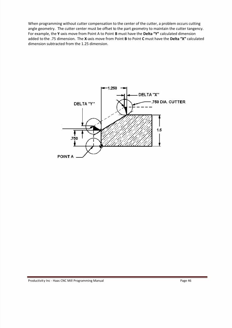
When programming without cutter compensation to the center of the cutter, a problem occurs cuttingangle geometry. The cutter center must be offset to the part geometry to maintain the cutter tangency.For example, the Y-axis move from Point A to Point B must have the Delta Y calculated dimensionadded to the .75 dimension. The X-axis move from Point B to Point C must have the Delta X calculateddimension subtracted from the 1.25 dimension.

8/20/2019 Haas-Mill-Programming-Manual.pdf
http://slidepdf.com/reader/full/haas-mill-programming-manualpdf 49/115
Productivity Inc - Haas CNC Mill Programming Manual Page 47
Cutter Compensation Exercise #1
Cutter will be a .500 diameter end mill. Start contour from the lower left corner of part and mill aroundoutside of part .375 deep. Mill around outside of part using cutter compensation for cutter offset andthen define the actual geometry of the part to position tool around part.
Cutter will be a ½ diameter End Mill; Mill around outside contour of part .375 deep using CutterCompensation.
O0020G00 G17 G40 G49 G80 G90 G98G00 G53 Z0T1 M06 (1/2 Diameter 4 flute. End Mill)G90 G54 G00 X______ Y_____ S1000 M03G43 H01 Z.1 M08G01 Z_____ F50.G__ X______ D_____ F10. (turn on cutter compensation)
Y______G0_ X______ Y_____ R_____G0_ X______G0_ X______ Y_____ R_____G0_ Y______
G0_ X______ Y_____ R_____G0_ X______G__ X______ Y_____ (turn off cutter compensation)G00 Z1. M09G00 G53 Z0 M05G00 G53 Y0M30
8/20/2019 Haas-Mill-Programming-Manual.pdf
http://slidepdf.com/reader/full/haas-mill-programming-manualpdf 50/115
Productivity Inc - Haas CNC Mill Programming Manual Page 48
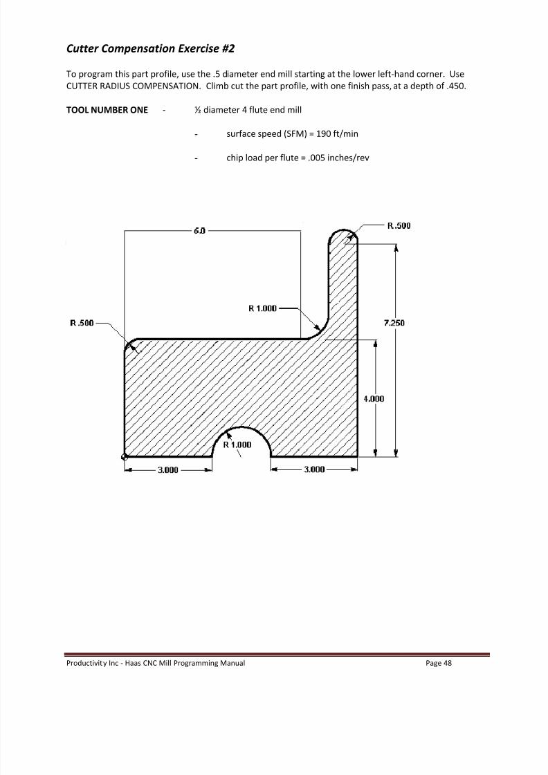
Cutter Compensation Exercise #2
To program this part profile, use the .5 diameter end mill starting at the lower left-hand corner. UseCUTTER RADIUS COMPENSATION. Climb cut the part profile, with one finish pass, at a depth of .450.
TOOL NUMBER ONE - ½ diameter 4 flute end mill
- surface speed (SFM) = 190 ft/min
- chip load per flute = .005 inches/rev

8/20/2019 Haas-Mill-Programming-Manual.pdf
http://slidepdf.com/reader/full/haas-mill-programming-manualpdf 51/115
Productivity Inc - Haas CNC Mill Programming Manual Page 49
O0057 (CUTTER COMPENSATION EXERCISE)
N1 G___G___G___G___G___G___G___ (SAFETY LINE)N2 G00 G53 Z0N3 T01 M__ (TOOL CHANGE)N4 G___ G___ G___ X-.35 Y-.25 M___S____N5 G___ Z.___ H___ M___N6 G___ Z-.____ F___N7 G4_ X____ D__N8 Y____N9 G___ X.____ Y____ R____N10 G___ X____N11 G___ X____ Y____ R____N12 G___ Y____N13 G___ X____ Y____ R____N14 G___ Y____N15 X____N16 G___ X____ Y____ R____N17 G___ X-.____N18 G4_ X-.____ Y-._____N19 G___ Z___ M___N20 G___ G___ Z____N21 G___ G___ Y____N22 M___

8/20/2019 Haas-Mill-Programming-Manual.pdf
http://slidepdf.com/reader/full/haas-mill-programming-manualpdf 52/115
Productivity Inc - Haas CNC Mill Programming Manual Page 50
Formulas Tapping, Speeds and Feeds
Tapping
STANDARD thread formula:
Feed rate in inches per minute = Revolutions per minute (RPM) divided by threads per inch (TPI)
F = RPM/TPIMETRIC thread formula:
Feed rate in inches per minute = Pitch (P) multiplied by .03937 multiplied by RPM
F = (P x .03937) x RPM
Speeds and Feeds
S.F.M. (Surface Feet per Minute):
SFM = .262 multiplied by the cutter diameter multiplied by the RPM
SFM = .262 x Cutter Diameter x RPM
R.P.M. (Revolutions per Minute):
RPM = 3.82 multiplied by the recommended SFM divided by the cutter diameter
RPM = 3.82 x SFM / Cutter Diameter
Feed (Inch per Minute) for twist drills :
F(inch/min) = F(inch /rev) x RPM
Feed (Inch per Minute) for end mills :
Feed rate in inches per minute = Feed per tooth (Inch/rev) multiplied by the number of cutterteeth multiplied by the RPM =
F (inch/min) = (Feed/tooth x n) x RPM
CUBIC INCH PER MINUTE:
Cubic inch per minute = Effective diameter of cut multiplied by the depth of cut multiplied by theinch per minute feed rate.
CIPM = (E Diameter x d) x IPM

8/20/2019 Haas-Mill-Programming-Manual.pdf
http://slidepdf.com/reader/full/haas-mill-programming-manualpdf 53/115

8/20/2019 Haas-Mill-Programming-Manual.pdf
http://slidepdf.com/reader/full/haas-mill-programming-manualpdf 54/115
Productivity Inc - Haas CNC Mill Programming Manual Page 52
Canned Cycles
A canned cycle is used to simplify programming of a part. Canned cycles are defined for the mostcommon Z-axis repetitive operations such as drilling, tapping, and boring. There are 13 canned cycles tochoose from. Once selected, a canned cycle is active until canceled with G80.
There are five operations involved in every canned cycle:1) positioning of X and Y axes (and optional A),2) rapid traverse to R plane,3) drilling, tapping and boring,4) operation at bottom of hole,5) retraction to R plane.
Once a Canned Cycle code is turned on, every time we move to a new X & Y location the machine will drill
a hole. This will continue until we cancel the drilling with a G80 code. This is how canned cycles save time.If we had 100 holes in a part, we would save 6000 lines of code in the example above.
Canned cycles are presently limited to only operations in the Z-axis. That is, only the G17 X-Y plane isallowed. This means that the canned cycle will be executed in the Z-axis whenever a position is selectedin the X or Y axes. The operation of a canned cycle will vary according to whether incremental (G91) orabsolute (G90) is active.
G98 and G99 are modal commands that change the way canned cycles operate. When G98 is active, theZ-axis will return to the start position (initial plane) when it completes an single operation. When G99 isactive, the Z-axis will be returned to the R point (plane) when the canned cycle completes a single hole.Then the machine will go to the next hole.

8/20/2019 Haas-Mill-Programming-Manual.pdf
http://slidepdf.com/reader/full/haas-mill-programming-manualpdf 55/115
Productivity Inc - Haas CNC Mill Programming Manual Page 53
The following is a summary of the canned cycles defined for the VF Series Mill:
GCode
Z DrillingDirection
Operation at Bottom ofHole
RetractionZ Direction Application
G73 Intermittent Feed None Rapid High Speed Peck DrillingG74 Feed Spindle CW Feed Left Hand TappingG76 Feed then Stop Orient Spindle Rapid Fine BoringG77 Rapid to Bottom Orient Spindle Back Bore/Rapid Back BoringG81 Feed None Rapid Spot DrillingG82 Feed Dwell Rapid Counter BoringG83 Intermittent Feed None Rapid Peck DrillingG84 Feed Spindle CCW Feed Tapping CycleG85 Feed None Feed Boring CycleG86 Feed Spindle Stop Rapid Boring CycleG87 Feed Spindle Stop Manual/Rapid Back BoringG88 Feed Dwell, then Spindle Stop Manual/Rapid Boring CycleG89 eed Dwell Feed Boring Cycle
Incremental motion in a canned cycle is often useful as a loop ( L) count, which can be used to repeat theoperation with an incremental X or Y move between each cycle.
NOTE : If an L0 is in the canned cycle line, the cycle will not execute until the control reads the next X or Y location.
The G80 code is used to cancel a canned cycle. In addition to this, a G00 or G01 code will also cancel anyactive canned cycle.
Once a canned cycle is defined, the canned cycle is repeated at every X-Y position in sequential blocks.
Some of the canned cycle numerical values can also be changed after the canned cycle is defined. Themost important of these are the R plane value and the Z depth value.
If these are changed in a block with an X-Y, the change doesn t take effect until the next block. Allsubsequent blocks are performed with the new R or Z value.
Changes to the G98/G99 selection can also be made after the canned cycle is active. If changed, the newG98/G99 value will be active in the next block and all subsequent blocks.

8/20/2019 Haas-Mill-Programming-Manual.pdf
http://slidepdf.com/reader/full/haas-mill-programming-manualpdf 56/115
Productivity Inc - Haas CNC Mill Programming Manual Page 54
G80 Canned Cycle Cancel
This G code is modal in that it deactivates all canned cycles G73, G74, G76, G77 , or G81-G89 until a newone is selected. Note that the use of G00 or G01 will also cancel a canned cycle.
G81 Drill Canned Cycle Straight Drilling without Peck
F Feed Rate in inches (mm) per minuteR Position of the R planeX Optional X-axis motion commandY Optional Y-axis motion commandZ Position of bottom of hole
N1 T1 M06N2 G90 G54 G00 X.3 Y.3N3 S1200 M03N4 G43 H01 Z1. M08N5 G81 Z-.6 R.1 F10.N6 X1.2 Y1.2N7 G80 G00 Z1. M09
N8 G28 G91 Z0. M05N9 M30
This G code is modal in that it activates the canned cycle until it is canceled or another canned cycle isselected. Once activated, every motion of X or Y will cause this canned cycle to be executed.

8/20/2019 Haas-Mill-Programming-Manual.pdf
http://slidepdf.com/reader/full/haas-mill-programming-manualpdf 57/115
Productivity Inc - Haas CNC Mill Programming Manual Page 55
G82 Spot Drill Canned Cycle Spot Drilling / Dwell
F Feed Rate in inches (mm) per minuteP The dwell time at the bottom of the hole in secondsR Position of the R planeX Optional X-axis motion commandY Optional Y-axis motion commandZ Position of bottom of hole
N1 T1 M06N2 G90 G54 G00 X.3 Y.3N3 S1200 M03N4 G43 H01 Z1. M08N5 G82 Z-.125 P1.5 R.1 F10.N6 X1.2 Y1.2N7 G80 G00 Z1. M09N8 G91 G28 Z0. M05N9 M30
This G code is modal in that it activates the canned cycle until it is canceled or another canned cycle isselected. Once activated, every motion of X or Y will cause this canned cycle to be executed.
8/20/2019 Haas-Mill-Programming-Manual.pdf
http://slidepdf.com/reader/full/haas-mill-programming-manualpdf 58/115
Productivity Inc - Haas CNC Mill Programming Manual Page 56
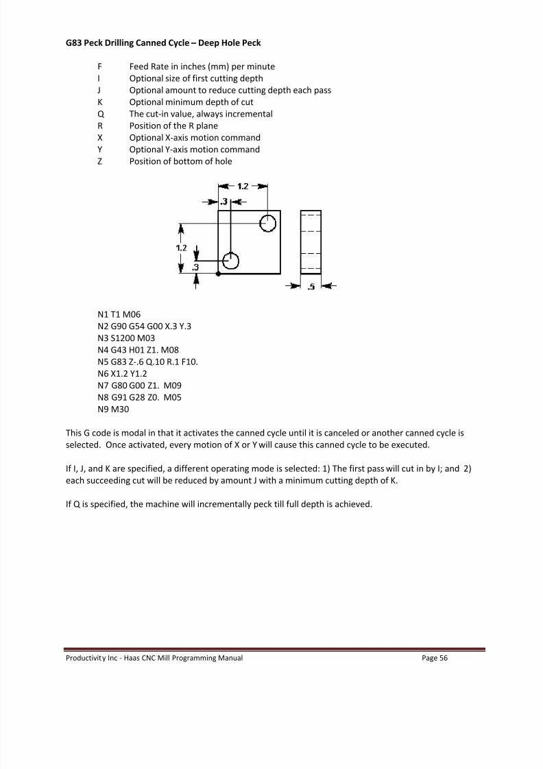
G83 Peck Drilling Canned Cycle Deep Hole Peck
F Feed Rate in inches (mm) per minuteI Optional size of first cutting depthJ Optional amount to reduce cutting depth each passK Optional minimum depth of cutQ The cut-in value, always incrementalR Position of the R planeX Optional X-axis motion commandY Optional Y-axis motion commandZ Position of bottom of hole
N1 T1 M06N2 G90 G54 G00 X.3 Y.3N3 S1200 M03N4 G43 H01 Z1. M08N5 G83 Z-.6 Q.10 R.1 F10.N6 X1.2 Y1.2N7 G80 G00 Z1. M09N8 G91 G28 Z0. M05N9 M30
This G code is modal in that it activates the canned cycle until it is canceled or another canned cycle isselected. Once activated, every motion of X or Y will cause this canned cycle to be executed.
If I, J, and K are specified, a different operating mode is selected: 1) The first pass will cut in by I; and 2)each succeeding cut will be reduced by amount J with a minimum cutting depth of K.
If Q is specified, the machine will incrementally peck till full depth is achieved.

8/20/2019 Haas-Mill-Programming-Manual.pdf
http://slidepdf.com/reader/full/haas-mill-programming-manualpdf 59/115
Productivity Inc - Haas CNC Mill Programming Manual Page 57

8/20/2019 Haas-Mill-Programming-Manual.pdf
http://slidepdf.com/reader/full/haas-mill-programming-manualpdf 60/115
Productivity Inc - Haas CNC Mill Programming Manual Page 58
Canned Cycle Exercise #1
TOOL NUMBER ONE
· ½ Diameter 90 Degree Spot Drill (use G81 cycle) · surface speed (SFM) = 190 ft/min· feed per. rev. = .0035 in/rev·
Drill to depth that will put .01 break on 3/8 counter bore
TOOL NUMBER TWO
· ¼ Diameter Drill, standard 118 degree (use G83 cycle)· surface speed (SFM) = 190 ft/min· feed per. rev. = .006 in/rev· Drill deep enough so flute goes .02 below bottom of part
TOOL NUMBER THREE
· 3/8 Diameter End Mill, 2 flute (use G82 cycle)· surface speed (SFM) = 190 ft/min· feed per. rev, per tooth. = .006 in/rev-tooth

8/20/2019 Haas-Mill-Programming-Manual.pdf
http://slidepdf.com/reader/full/haas-mill-programming-manualpdf 61/115
Productivity Inc - Haas CNC Mill Programming Manual Page 59
O0067 (CANNED CYCLE EXERCISE)
G___G___G___G___G___G___G___ (SAFETY LINE)N1 (1/2 DIA. SPOT DRILL)G___ G___ Z_____T___ M___G___ G___ G___ X.____ Y.____ M___S_____G___ Z____. H___ M____G___ Z-.____ R___ F____Y____X____Y____G___ G___ Z___ M___G___ G___ Z___M___N2 (1/4 DIA. DRILL)T___ M____G___ G___ G___ X____ Y____ M___ S_____G___ Z____ H___ M___G___ Z-___ R__ F____ Q____Y____X____Y____G___ G___ Z____ M___G___ G___ Z____M__N3 (3/8 DIA. ENDMILL)T___ M____G___ G___ G___ X____ Y____ M___ S_____G___ Z____ H___ M___G___ Z-____ R____ F___ P_____Y____X____Y____G___ G___ Z____ M___G___ G___ Z____G___ G___ Y____M___

8/20/2019 Haas-Mill-Programming-Manual.pdf
http://slidepdf.com/reader/full/haas-mill-programming-manualpdf 62/115
Productivity Inc - Haas CNC Mill Programming Manual Page 60
G84 Tapping Canned Cycle Tapping with RH ThreadsG74 Tapping Canned Cycle Tapping with LH Threads
You do not need to turn on the spindle for a tap when using G84 because G84 will do it for you.G84 or G74 do however require a (S) spindle speed value described in the code.
F Feed Rate in inches (mm) per minuteR Position of the R planeX Optional X-axis motion commandY Optional Y-axis motion commandZ Position of bottom of hole
N1 T1 M06N2 G90 G54 G00 X.3 Y.3N3 S1200 (you do not need to turn spindle on)N4 G43 H01 Z1. M08N5 G84 Z-.85 R.1 F60.N6 X1.2 Y1.2N7 G80 G00 Z1. M09N8 G91 G28 Z0. M05N9 M30
This G code is modal in that it activates the canned cycle until it is canceled or another canned cycle isselected. Once activated, every motion of X or Y will cause this canned cycle to be executed. When rigidtapping is used, the ratio between the feed rate and spindle speed must be precisely the thread pitchbeing cut.
You do not need to start the spindle CW before this canned cycle. The control does this automatically.
Setting 130 Tap Retract Speed (Allows retract to be two to four times faster)
Setting 133 Repeat Rigid Tap (Allows holes to be re-tapped)
8/20/2019 Haas-Mill-Programming-Manual.pdf
http://slidepdf.com/reader/full/haas-mill-programming-manualpdf 63/115
Productivity Inc - Haas CNC Mill Programming Manual Page 61
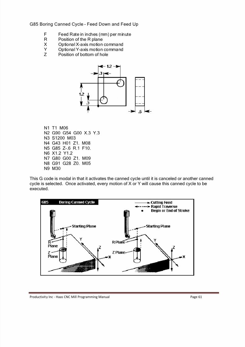
G85 Boring Canned Cycle Feed Down and Feed Up
F Feed Rate in inches (mm) per minuteR Position of the R planeX Optional X-axis motion commandY Optional Y-axis motion commandZ Position of bottom of hole
N1 T1 M06N2 G90 G54 G00 X.3 Y.3N3 S1200 M03N4 G43 H01 Z1. M08N5 G85 Z-.6 R.1 F10.N6 X1.2 Y1.2N7 G80 G00 Z1. M09N8 G91 G28 Z0. M05N9 M30
This G code is modal in that it activates the canned cycle until it is canceled or another cannedcycle is selected. Once activated, every motion of X or Y will cause this canned cycle to beexecuted.

8/20/2019 Haas-Mill-Programming-Manual.pdf
http://slidepdf.com/reader/full/haas-mill-programming-manualpdf 64/115

8/20/2019 Haas-Mill-Programming-Manual.pdf
http://slidepdf.com/reader/full/haas-mill-programming-manualpdf 65/115
Productivity Inc - Haas CNC Mill Programming Manual Page 63
O0071 (CANNED CYCLE EXERCISE)
N1 (5/8 DIA. SPOT DRILL)G00 G17 G40 G49 G80 G90G98G___ G____ Z____
T___ M___G___ G___ G___ X.____ Y.____ M___S_____G___ Z____ H___ M___G___ Z-.____ R___ F____X_____X_____X_____Y_____X_____X_____Y_____
X_____X_____G___ G___ Z____ M___G___ G___ Z____M__N2 (27/64 DIA. DRILL)T___ M___G___ G___ G___ X____ Y____ M___ S_____G___ Z____ H___ M____
G___Z-____ R____ F____ Q____X_____X_____X_____Y_____X_____X_____Y_____X_____X_____G___ G___ Z____ M___
G___ G___ Z____M__
8/20/2019 Haas-Mill-Programming-Manual.pdf
http://slidepdf.com/reader/full/haas-mill-programming-manualpdf 66/115
Productivity Inc - Haas CNC Mill Programming Manual Page 64
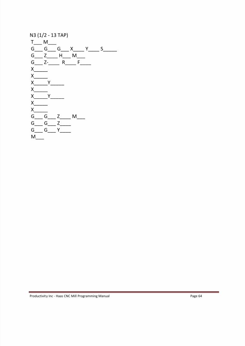
N3 (1/2 - 13 TAP)T___ M___G___ G___ G___ X____ Y____ S_____G___ Z____ H___ M___G___ Z-____ R____ F____X_____X_____X_____Y_____X_____X_____Y_____X_____X_____G___ G___ Z____ M___G___ G___ Z____G___ G___ Y____M___

8/20/2019 Haas-Mill-Programming-Manual.pdf
http://slidepdf.com/reader/full/haas-mill-programming-manualpdf 67/115
Productivity Inc - Haas CNC Mill Programming Manual Page 65
G89 Bore Canned Cycle (feed down, dwell, jog out)
F Feed Rate in inches (mm) per minuteP The dwell time at the bottom of the holeR Position of the R planeX Optional X-axis motion commandY Optional Y-axis motion commandZ Position of bottom of hole
N1 T1 M06N2 G90 G54 G00 X.3 Y.3N3 S1200 M03N4 G43 H01 Z1. M08N5 G89 Z-.6 P1.0 R.1 F10.N6 X1.2 Y1.2N7 G80 G00 1Z M09N8 G91 G28 Z0. M05N9 M30
This G code is modal in that it activates the canned cycle until it is canceled or another canned cycle isselected. Once activated, every motion of X or Y will cause this canned cycle to be executed.

8/20/2019 Haas-Mill-Programming-Manual.pdf
http://slidepdf.com/reader/full/haas-mill-programming-manualpdf 68/115
Productivity Inc - Haas CNC Mill Programming Manual Page 66
G73 High Speed Peck Drilling Canned Cycle
F Feed Rate in inches (mm) per minuteI Optional size of first cutting depthJ Optional amount to reduce cutting depth each passK Optional minimum depth of cutQ The cut-in value, always incrementalR Position of the R planeX Optional X-axis motion commandY Optional Y-axis motion commandZ Position of bottom of hole
N1 T1 M06N2 G90 G54 G00 X.3 Y.3N3 S1200 M03N4 G43 H01 Z1. M08N5 G73 Z-.6 Q.25 R.1 F10.N6 X1.2 Y1.2N7 G80 G00 Z1. M09N8 G91 G28 Z0. M05N9 M30
This G code is modal in that it activates the canned cycle until it is canceled or another canned cycle isselected. Once activated, every motion of X or Y will cause this canned cycle to be executed. This cycle isa high speed peck cycle where a retract distance is set by Setting 22 .
I, J, K, and Q are always positive numbers.
Setting 52 also changes the way G73 works when it returns to the R plane. Most programmers set the Rplane well above the cut to ensure that the chip clear motion actually allows the chips to get out of thehole, but this causes a wasted motion when first drilling through this empty space. If Setting 52 is set tothe distance required to clear chips, the R plane can be put much closer to the part being drilled. Whenthe clear move to R occurs, the Z will be moved above R by this setting.
If I, J, and K are specified with G73, a different operating mode is selected. The first pass will cut in by I,each succeeding cut will be reduced by amount J with a minimum cutting depth of K.
If K and Q are both specified, a different operating mode is selected for this canned cycle. In this mode,the tool is returned to the R plane after a number of passes totals up to the K amount. This allows muchfaster drilling than G83, but still returns to the R plane occasionally to clear chips.

8/20/2019 Haas-Mill-Programming-Manual.pdf
http://slidepdf.com/reader/full/haas-mill-programming-manualpdf 69/115
Productivity Inc - Haas CNC Mill Programming Manual Page 67
G74 Reverse Tap Canned Cycle
F Feed Rate in inches (mm) per minuteR Position of the R planeX Optional X-axis motion commandY Optional Y-axis motion commandZ Position of bottom of hole
N1 T1 M06N2 G90 G54 G00 X.3 Y.3N3 S1200N4 G43 H01 Z1. M08N5 G74 Z-.6 R.1 F60.N6 X1.2 Y1.2N7 G80 G00 Z1. M09N8 G91 G28 Z0. M05N9 M30
This G code is modal in that it activates the canned cycle until it is canceled or another canned cycle isselected. Once activated, every motion of X or Y will cause this canned cycle to be executed. Note thatoperation of this cycle is different if the rigid tapping option is installed and selected. When rigid tappingis used, the ratio between the feed rate and spindle speed must be precisely the thread pitch being cut.
You do not need to start the spindle CCW before this canned cycle. The control does this automatically.

8/20/2019 Haas-Mill-Programming-Manual.pdf
http://slidepdf.com/reader/full/haas-mill-programming-manualpdf 70/115
Productivity Inc - Haas CNC Mill Programming Manual Page 68
G76 Fine Boring Canned Cycle (feed down, spindle stop, orient spindle, step over, rapid out)
F Feed Rate in inches (mm) per minuteI Optional shift value (in x-axis), if Q is not specifiedJ Optional shift value (in y-axis), if Q is not specified.P The dwell time at the bottom of the holeQ The shift value, always incrementalR Position of the R planeX Optional X-axis motion commandY Optional Y-axis motion commandZ Position of bottom of hole
N1 T1 M06N2 G90 G54 G00 X.3 Y.3N3 S1200 M03N4 G43 H01 Z1. M08N5 G76 Z-.6 R.1 F10. Q.02N6 X1.2 Y1.2N7 G80 G00 Z1. M09
N8 G91 G28 Z0. M05N9 M30
This cycle will shift the X and/or Y-axis prior to retracting in order to clear the tool while exiting the part.This shift direction is set by Setting 27 .
The Q value distance will shift in the direction set by Setting 27. If Q is not specified, the optional I and Jvalues are used to determine the shift direction and distance.

8/20/2019 Haas-Mill-Programming-Manual.pdf
http://slidepdf.com/reader/full/haas-mill-programming-manualpdf 71/115
Productivity Inc - Haas CNC Mill Programming Manual Page 69
CANNED CYCLE AUXILIARY FUNCTIONS
G98 Canned Cycle Initial Point Return
This G code is modal and changes the way canned cycles operate. With G98, the canned cycle will return
to the initial starting point of the canned cycle when it completes a hole before moving to the next hole.
G99 Canned Cycle R Plane Return
This G code is modal and changes the way canned cycles operate. With G99, the canned cycle will returnto the R plane when the canned cycle completes before moving to the next hole.
8/20/2019 Haas-Mill-Programming-Manual.pdf
http://slidepdf.com/reader/full/haas-mill-programming-manualpdf 72/115
Productivity Inc - Haas CNC Mill Programming Manual Page 70
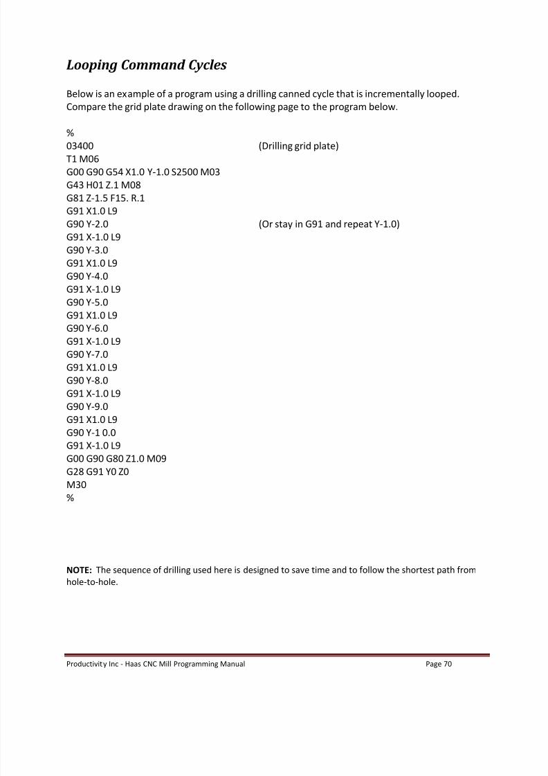
Looping Command Cycles
Below is an example of a program using a drilling canned cycle that is incrementally looped.Compare the grid plate drawing on the following page to the program below.
%03400 (Drilling grid plate)T1 M06G00 G90 G54 X1.0 Y-1.0 S2500 M03G43 H01 Z.1 M08G81 Z-1.5 F15. R.1G91 X1.0 L9G90 Y-2.0 (Or stay in G91 and repeat Y-1.0)G91 X-1.0 L9G90 Y-3.0G91 X1.0 L9G90 Y-4.0G91 X-1.0 L9G90 Y-5.0G91 X1.0 L9G90 Y-6.0G91 X-1.0 L9G90 Y-7.0G91 X1.0 L9G90 Y-8.0G91 X-1.0 L9
G90 Y-9.0G91 X1.0 L9G90 Y-1 0.0G91 X-1.0 L9G00 G90 G80 Z1.0 M09G28 G91 Y0 Z0M30%
NOTE: The sequence of drilling used here is designed to save time and to follow the shortest path fromhole-to-hole.

8/20/2019 Haas-Mill-Programming-Manual.pdf
http://slidepdf.com/reader/full/haas-mill-programming-manualpdf 73/115
Productivity Inc - Haas CNC Mill Programming Manual Page 71

8/20/2019 Haas-Mill-Programming-Manual.pdf
http://slidepdf.com/reader/full/haas-mill-programming-manualpdf 74/115
Productivity Inc - Haas CNC Mill Programming Manual Page 72
Bolt Hole Patterns
There are three G codes that provide patterns usually used for bolt holes. These are G70, G71, and G72.These G codes must be used with one of the canned cycles G73, G74, G76, G77, or G81-G89. The startingangle is from 0 to 360.0 degrees CCW from horizontal starting from Three o clock.
G70 Bolt Hole Circle
I Radius (Minus Reverses Starting Position)J Starting angle (0 to 360.0 degrees CCW from horizontal)L Number of holes evenly spaced around the circle
The tool must be positioned at the center of the circle either in a previous block or in the G70 block. G70belongs to Group zero and thus is non-modal. For a G70 to work correctly, a canned cycle should be activeso that at each of the positions, some type of drill or tap cycle is performed.
G71 Bolt Hole Arc
I RadiusJ Starting angle (degrees CCW from horizontal)K Angular spacing of holes (+ or -)L Number of holes)
This G code is similar to G70 except that it is not limited at one complete circle. G71 belongs to Groupzero and thus is non-modal. For a G71 to work correctly, a canned cycle should be active so that at each ofthe positions, some type of drill or tap cycle is performed.
G72 Bolt Holes Along An Angle
This G code drills L holes in a straight line at the specified angle. It operates similarly to G70 and G71. G72belongs to Group zero and thus is non-modal. For a G72 to work correctly, a canned cycle should be activeso that at each of the positions, some type of drill or tap cycle is performed.
Example of G70 Bolt Hole Circle program used in conjunction with G83 Peck Drill Cycle.
%O100T1 M6G0 G90 G54 X0 Y0 S1000 M3G43 H1 Z1.0 M8
G83 Z-2.0 R.1 Q.2 F1.5 L0G70 I1.0 J0 L8G00 G80 Z1.0 M9G53 Z0G53 Y0M30%

8/20/2019 Haas-Mill-Programming-Manual.pdf
http://slidepdf.com/reader/full/haas-mill-programming-manualpdf 75/115

8/20/2019 Haas-Mill-Programming-Manual.pdf
http://slidepdf.com/reader/full/haas-mill-programming-manualpdf 76/115
Productivity Inc - Haas CNC Mill Programming Manual Page 74
Four Bolt Hole Circle Exercise: Drill 1/8 holes ¼ deep in .5 thick plate. Spot drill deep to leave .012chamfer on 1/8 holes.
T1 1/4 90 DEG SPOT DRILL 80 FT/MIN .003 IN/REVT2 1/8 CONVENTIONAL DRILL 80 FT/MIN ., .003 IN/REV
O03901 (1 Ø BHC)N1 (1/2 DIAM SPOT DRILL)G00 G17 G40 G49 G80 G90 G98G00 G53 Z0T1 M06 (1/4 90 DEG SPOT DRILL)G00 G90 G54 X______ Y______ M03 S_____G43 H01 Z1. M08G___ Z-______ R____ F____ L___G___ I____ J____ L__X____ Y____ L__G___ I___ J__ L___X____ Y____ L___
G___ I____ J__ L__X____ Y____ L__G___ I____ J___ L__G00 G____ Z1. M09G00 G53 Z0M01
8/20/2019 Haas-Mill-Programming-Manual.pdf
http://slidepdf.com/reader/full/haas-mill-programming-manualpdf 77/115
Productivity Inc - Haas CNC Mill Programming Manual Page 75
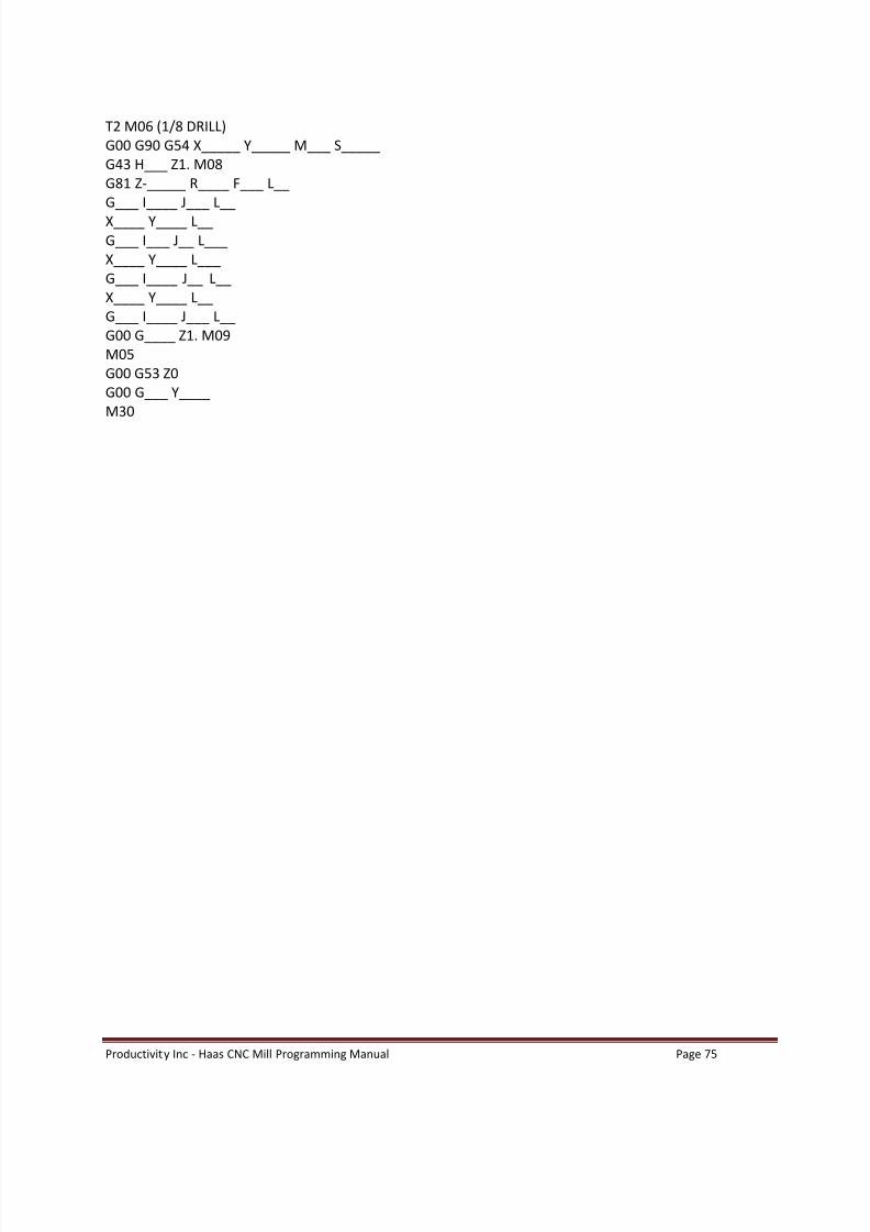
T2 M06 (1/8 DRILL)G00 G90 G54 X_____ Y_____ M___ S_____G43 H___ Z1. M08G81 Z-_____ R____ F___ L__G___ I____ J___ L__X____ Y____ L__G___ I___ J__ L___X____ Y____ L___G___ I____ J__ L__X____ Y____ L__G___ I____ J___ L__G00 G____ Z1. M09M05G00 G53 Z0G00 G___ Y____M30

8/20/2019 Haas-Mill-Programming-Manual.pdf
http://slidepdf.com/reader/full/haas-mill-programming-manualpdf 78/115
Productivity Inc - Haas CNC Mill Programming Manual Page 76

8/20/2019 Haas-Mill-Programming-Manual.pdf
http://slidepdf.com/reader/full/haas-mill-programming-manualpdf 79/115
Productivity Inc - Haas CNC Mill Programming Manual Page 77
Canned Cycle Exercise #3
Program with a 1/4 Diameter Drill, 118 at 210 SFM with feed of .005 in/rev. (Use the HAAS calculator toget the spindle speed and feed.) Define A rapid plane .050 up from the bottom of circular pocket for BoltHole Circle and Bolt Hole Arc . Rapid plane for Bolt Holes at an Angle changes back to .1 above Z zero topof part.
NOTE : If an L0 is in the canned cycle line, the cycle will not execute that command until the
control reads the next X and/or Y location.
O0010 (put this in after tool #2, but right before the M30 on program O0010)T03 M06 (T3 1/4 Diameter Carbide Stub Drill)G____ G____ G____ X____ Y____ S____ M____ (XY position to center of bolt circle)G____ H____ Z____ M____G____ G____ Z____ R____ F____ (drilling canned cycle with initial point return )G____ I____ J____ L____ (Bolt Hole Circle Command)X____ Y____ L____ (XY position center of bolt hole arc, but do not drill a hole here)G____ I____ J____ K ____L ____G____ X____ Y____ I____ J____ L____ R____ Z____ (Bolt hole at an angle and change the R plane)G____ G____ Z____ M____G____ G____ Y____ Z____M____

8/20/2019 Haas-Mill-Programming-Manual.pdf
http://slidepdf.com/reader/full/haas-mill-programming-manualpdf 80/115
Productivity Inc - Haas CNC Mill Programming Manual Page 78
Additional G Codes
G04 Dwell
P code The dwell time in seconds or milliseconds.
G04 is used to cause a delay or dwell in the program. The block containing G04 will delay for the timespecified in the P code. When programmed on a line following some motion, such as G00, G01, G02 andG03, all motion will be stopped for the amount of time specified in the P command in seconds. If the P has no fraction part, the delay is in milliseconds (0.001 seconds); otherwise, the delay is in seconds.
The slide motion is stopped, but the spindle will continue to rotate at the requested RPM and the coolantwill stay on.
G04 P____
Minimum value P.001 of a secondMaximum value P1000. Seconds

8/20/2019 Haas-Mill-Programming-Manual.pdf
http://slidepdf.com/reader/full/haas-mill-programming-manualpdf 81/115
Productivity Inc - Haas CNC Mill Programming Manual Page 79
Milling Circles with Cutter Comp
Cutter compensation may be turned on when milling circles. This provides control over the size of thecircular pocket by making small changes in the wear of the diameter of the tool used.
Below G3 I-.500 J0 will create a counter clockwise 1.0 inch pocket after turning on the G41 cutter comp.Tool is placed at the center X and Y coordinates of the pocket to be milled.Tool is taken to depth. Then G41 is turned on to go to the X coordinate of the edge of the finish pocket. Acounter clockwise arc is then created with G3 I-.500 J0 going along the outside of the pocket giving a 1.0inch pocket. Then G40 is turned on return to the center of the pocket.
O10000;G0 G90 G53 G49 Z0;T1 M6 (1/2 E-Mill D1=.250);G0 G90 G54 X.750 Y-.750 M3 S3500;G43 H1 Z1.0 M8;Z.1;
G1 Z-.375 F5.;G41 X1.25 D1 F20.;G3 I-.500 J0;G1 G40 X.750 Y-.750;G0 Z1.0 M9;G0 G90 G53 G49 Z0 M5;M30;%

8/20/2019 Haas-Mill-Programming-Manual.pdf
http://slidepdf.com/reader/full/haas-mill-programming-manualpdf 82/115
Productivity Inc - Haas CNC Mill Programming Manual Page 80
Thread Milling
Thread milling uses a standard G02 or G03 move to create the circular move in X-Y, then adds a Z move onthe same block to create the thread pitch. This generates one turn of the thread; the multiple teeth of thecutter generate the rest.
Typical line of code: N100 G02 I-1.0 Z-.05 F5 . (this will generate an 1-inch radius for a 20-pitch thread)Thread Milling notes: Internal holes smaller than 3/8 inch may not be possible or practical. Always climbcut the cutter. Use a G03 to cut I.D. threads or a G02 to cut O.D. threads. An I.D. right hand thread willmove up in the Z-axis by the amount of one thread pitch. An O.D.right hand thread will move down in the Z-axis by the amount of one thread pitch. PITCH = 1/Threads perinch (Example - 1.0 divided by 8 TPI = .125)
Thread Milling Example:
O02300 (Thread milling 1.5 x 8 TPI)T1 M06 (0.5 DIA 2FLT. THREAD MILL)
G00 G90 G54 X0. Y0. S1910 M03 (X0. Y0. is at the center of the hole)G43 H01 Z0.1 M08 (Z0. is at the top of the part - using .5 thick material)G00 Z-0.6N1 G01 G41 D01 X0.125 F30. (Turn on Cutter Comp)N2 G03 X0.75 Y0. R0.3125 F11.5 (Arc on to the I.D. of bored hole)N3 G03 I-0.75 Z-0.475 (One full revolution with Z moving up .125)N4 G03 X0.125 Y0. R0.3125 F30. (Move away from the new threads)N5 G01 G40 X0. Y0. (Cancel Cutter Comp)G00 Z0.1 M09G28 G91 Y0. Z0.M30
This program will I.D. thread mill a 1.5 x 8 TPI hole using a .750 diameter x 1.0 thread hob.To start, take the hole diameter (1.500). Subtract the cutter diameter .750 andThen divide by 2. (1.500 - .75) / 2 = .375The result (.375) is the distance the cutter starts from the I.D. of the part. After the initial positioning, thenext step of the program is to turn on cutter compensation and move to the I.D. of the circle. The nextstep is to program a complete circle (G02 or G03) with a Z-axis command of the amount of one full pitch ofthe thread (this is called helical interpolation )The last step is to move away from the I.D. of the circle and turn off cutter compensationCutter compensation cannot be turned off or on during an arc movement. A linear move must be made,either in the X or Y axis to move the tool to and from the diameter to cut. This move will be the maximumcompensation amount that can be adjusted

8/20/2019 Haas-Mill-Programming-Manual.pdf
http://slidepdf.com/reader/full/haas-mill-programming-manualpdf 83/115
Productivity Inc - Haas CNC Mill Programming Manual Page 81
Circular Pocket Milling using G12 and G13
The Haas control has included in its software a Yasnac style circular pocket milling program (G12 clockwisecircular pocket.G13 Counterclockwise Pocket). These G codes imply the use of cutter compensation, i.e., aG41 or G42 is not required to be stated in the program line. However, a D -- offset number for cutterradius or diameter is required for the ability to adjust the circle diameter.In this section, we will cover the G12 and G13 format, as well as the different ways these programs can bewritten for many various applications:
SINGLE PASS: UsingI only.
APPLICATIONS: One-pass counter boring; rough and finish pocketing of smaller holes; I.D. keyway cutting;"O"-ring grooves.
MULTIPLE PASS: UsingI, K, and Q .
APPLICATIONS: Multiple-pass counter boring, rough and finish pocketing of large holes with
cutter overlap
MULTIPLE Z DEPTH PASS: Using I only, or, I, K, and Q . (G91 and L)
APPLICATIONS: Deep rough and finish pocketing; incremental Z depth stepping.
NOTE: The tool must be positioned at the center of the circle, either in a previous block orin the G12/Gl3 line by using Xand Y.
There are two G codes, G12 and G13, that will provide for pocket milling of a circular shape. They aredifferent only in the direction of rotation that is used.
G12, G13 Circular Pocket Milling Group 00
D* Tool Geometry Offset SelectionI Radius Of First Circle (Or Finish If No K)K Radius Of Finished Circle (if using I, K, and Q)L Loop Count For Incremental Z Depth SteppingQ Radius Increment Or StepoverF Feed Rate in Inches (mm) per minuteZ Z Depth Of Cut Or Increment
*In order to get the exact programmed circle diameter, the control uses the selected D code tool size. Ifthis compensation is not desired, program D0.
This G12 Code implies the use of G42 and will mill clockwise.

8/20/2019 Haas-Mill-Programming-Manual.pdf
http://slidepdf.com/reader/full/haas-mill-programming-manualpdf 84/115
Productivity Inc - Haas CNC Mill Programming Manual Page 82
The tool must be positioned at the center of the circular pocket, either in a previous block or in thiscommand using X and Y position. The cut is performed entirely with circular motions of varying radius .G12 belongs to Group zero and thus is non-modal. If G91 (incremental) is specified and an L count isincluded, the Z increment is repeated L times at the F feed rate command. If no K is specified, the centerroughing passes of this command are removed completely and only one finish pass of the circular pocketis performed.
G13 Circular Pocket Milling Counterclockwise
This G code implies the use of G41 and is otherwise the same as G12. G13 belongs to Group 00 and thus isnon-modal.
EXAMPLE: G13 Single Pass Using I Only
02345 (.500 entered in the radius/diameter offset column)T1 M06 (Tool #1 is a .500 diameter end mill)G90 G54 G00 X1.5 Y1.5 (XY position of center on circular pocket)S3600 M03G43 H01 Z.1 M08G13 Z-.75 I.5 D01 F15. (will complete a 1.0 diameter hole in one pass)G00 Z1.0 M09G28 G91 Y0 Z0M30
EXAMPLE: G13 Multiple Pass Using I , K , and Q
03456 (.750 entered in the radius/diameter offset column)T3 M06 (Tool #3 is a .750 diameter end mill)G90 G54 G00 X.5 Y1.5 (XY position of center on circular pocket)S3600 M03G43 H01 Z.1 M08G1 Z0 F15.G13 G91 Z-.5 I.65 K2. Q.65 D03 L4 F15. (will complete a 4.0 diameter hole in four passes)G00 Z1.0 M09G28 G91 Y0 Z0M30
The last program uses G91 and an L count of four. This cycle is multiplied by the L command and willexecute a total of four times at the Z depth increment of .500 to a total depth of 2.0 inches.
The G91 and L count can also be used in G12 and G13 I only line.
The figure below shows the tool path during the G12 and G13 cycles. One uses I only and the other uses I,K, and Q .

8/20/2019 Haas-Mill-Programming-Manual.pdf
http://slidepdf.com/reader/full/haas-mill-programming-manualpdf 85/115
Productivity Inc - Haas CNC Mill Programming Manual Page 83
Example of one pass milling using only the I variable.
Milling a 0.8 diameter 0.5 deep pocket using a 0.5 end mill. The picture shows the tool path for thecode given. Note with G12 a clockwise rotation is created where the mill is conventional cutting.
G12 Z-0.5 I0.4 D01 F15
Example of multiple pass milling using I, K, and Q variables. The code is also turned into incrementalpositioning with G91 and an L added. So the code is repeated 3 times stepping down Z-.5 each pass.
Milling a 3.0 diameter 1.5 deep pocket using a 0.5 end mill.
O0010 ;T1 M06 ;G90 G54 G00 X1.0 Y1.0 ;S1500 M03 ;G43 Z0.1 H1 M08;
G1 Z0 F30.G13 G91 Z-0.5 I0.3 K1.5 Q0.3 D01 F15. L3;G90 ;G00 Z0.1 M09 ;G28 G91 Y0 Z0 ;M30 ;
Note the motion of the cutter is counter clockwise using G13 instead of G12. The radius of the first pass isdetermined by I.3. First the ½ end mill plunges in creating ½ hole, then the first cut creates a .6 diameterpocket with I .3. The second cut adds Q.3 to the I.3 to equal a .6 radius cut out to a 1.2 diameter.
Additional cuts are added with the Q.3 step over until the final K radius or finish pass is completed. Thenthe whole process is repeated two more times stepping down incrementally the Z-.5. The final pocketdepth equals 3 x .5 to give 1.5. The above illustrations just show the initial step of three.
Note the end mill is positioned at the center of the pocket and fed down to Z0 the top face of the part.
The above illustrations and some text taken from Haas Microsoft PowerPoint titled Unique G-Codes.

8/20/2019 Haas-Mill-Programming-Manual.pdf
http://slidepdf.com/reader/full/haas-mill-programming-manualpdf 86/115
Productivity Inc - Haas CNC Mill Programming Manual Page 84
Circular Pocket Milling Exercise
G12 Circular Pocket Milling CWOr
G13 Circular Pocket Milling CCWD - Tool Radius or Diameter Selection
I - Radius of First Circle(Or finish If K is not used)
K - Radius of Finished Circle(if specified)
L - Loop count for repeating deeper cutsQ - Radius step over Increment
(must be used with K)F - Feedrate in inches (mm) per minuteZ - Z Depth of cuts or increments
CPM1
Circular Pocket Mill CPM 1 to a depth of .250 and spiral out to size using I, K and Q. Pocket mill anothercommand to run on CPM 1 using I only as a finish pass.
CPM2
Circular Pocket Mill CPM 2 a 2.0 Diameter x .250 depth pocket and incremental stepping down .05 depthusing an L count and a G91 incremental command.
Program with a ¾ Diameter 2 flute E.M. at 190 SFM with .0065 in/rev per flute. (Use the HAAS calculatorto get the spindle speed and feed.)
(Put this program in after tool #1, but right before the T3 on program O0010)

8/20/2019 Haas-Mill-Programming-Manual.pdf
http://slidepdf.com/reader/full/haas-mill-programming-manualpdf 87/115

8/20/2019 Haas-Mill-Programming-Manual.pdf
http://slidepdf.com/reader/full/haas-mill-programming-manualpdf 88/115
Productivity Inc - Haas CNC Mill Programming Manual Page 86
Circular Plane Selection
The plane used for circular motions must be comprised of two of the X, Y, or Z axes. The plane selection ismodal and will stay in effect for all subsequent circular interpolation commands until canceled by another
plane selection code. There are three G codes used to select the circular plane: G17 for XY, G18 for XZ, andG19 for YZ.
G17 XY Circular Plane Selection
The G17 code is used to select the XY plane for circular motion. In this plane, circular motion is defined asclockwise for the operator looking down onto the X-Y table from above.
G18 XZ Circular Plane Selection
The G18 code is used to select the XZ plane for circular motion. In the X-Z plane (G18), circular motion isdefined as clockwise for the operator looking towards the rear of the machine from the front controlpanel.
G19 YZ Circular Plane Selection
The G19 code is used to select the YZ plane for circular motion. In the Y-Z plane (G19), circular motion isdefined as clockwise for the operator looking across the table from the side of the machine the controlpanel is mounted.
The default plane selection, when the machine is powered on, is G17 for the X-Y plane. This means that acircular motion in the plane of the X-Y table may be programmed without first selecting G17. A helicalmotion is possible with G02 or G03 by programming the linear axis, which is not in the selected plane.
This third axis will be interpolated along the specified axis in a linear manner while the other two axes willbe moved in the circular motion. The speed of each axis will be controlled so that the helical rate matchesthe programmed feed rate.
If cutter radius compensation is selected (G41 or G42), you may only use the X-Y plane for circular motions(G17). Cutter radius compensation is only available in the X and Y axes.

8/20/2019 Haas-Mill-Programming-Manual.pdf
http://slidepdf.com/reader/full/haas-mill-programming-manualpdf 89/115
Productivity Inc - Haas CNC Mill Programming Manual Page 87
Inch / Metric Selection (G20, G21)
G20 Inch Programming SelectionG21 Metric Programming Selection
Selection between inch and metric programming can only be done from Setting 9 . Inch programmingallows displacements up to 838 inches and a resolution of 0.0001 inches. Metric programming usesmillimeter units with a maximum displacement of 8380 mm and a resolution of 0.001 mm.
When in metric, the feed rate is also defined as millimeters per minute with a range of 1000 to 0.001mm/min.
When jogging in metric, the speeds and units on the keypad are interpreted as mm/min, but the valueused is ten times larger than shown on the keypad.
The optional fourth or fifth axis programming is not affected by the selection of metric; it is alwaysprogrammed in degrees. The auxiliary C axis is also always in degrees.
Changing the setting from inches to metric or back again will change the content of any programs alreadystored in memory. Programs must be reloaded with metric values after changing this setting.
The standard G codes, G20 and G21, are sometimes used to select between inch and metric, however , inthis control, the G20 (inch) and G21 (mm) codes can only be used to ensure that the inch/metric setting isset correctly for that program.
Reference Point Definition and Return
G28 Return To Reference Point, Set Optional Intermediate Point
The G28 code is used to return to the machine zero position on all axes. If an X, Y, Z, or A axis is on thesame block and specifies a location, only those axes will move and return to the machine s zero referencepoint and the movement to the machine s zero reference point will be through that specified location.This point is called the intermediate point and is saved, if needed, for use in G29. If you do not want toposition through an intermediate point while specifying a specific axis to position to machine zero, thenadd an incremental (G91) command to this line along with a Z0, Y0, and/or X0 for the specific axis youwant to send to machine zero. This will command those axes specified to position incrementally to a zerodistance as an intermediate point, and then those axes specified will then position to machine zero. Besure to program in an absolute (G90) command in the startup lines for the next tool, which is usuallyneeded for the beginning of each tool.
If no X, Y, Z, or A is specified, all axes will be moved directly to machine zero. Any auxiliary axes (B, C, )are returned to their machine home after the X, Y, Z, and A axes. G28 also cancels tool length offsets.

8/20/2019 Haas-Mill-Programming-Manual.pdf
http://slidepdf.com/reader/full/haas-mill-programming-manualpdf 90/115
Productivity Inc - Haas CNC Mill Programming Manual Page 88
Setting Work, Tool Offsets through the Program (G10)
The G10 code can set or change tool and work offset within the program. This code may be used whendedicated work holding fixtures and tools are used to reduce set up time.
Definitions: L- Selects an offset categoryL2 Work coordinate offset for G52 and G54-G59L20 Auxiliary work coordinate offsets for G110-G129, G154L10 Tool Length offset (for H code)L1 or L11 Tool wear offset (for H code)L12 Diameter Offset (for D code)L13 Diameter Wear offset (for D code)
P- Selects a specific offsetP0 G52 references work coordinate (L2)P1-P6 references work coordinates respectively G54-G59 (L2)P1-P20 references auxiliary work coordinates G110-G129 (L20)P1-P99 references auxiliary work coordinates G154 P1-P99 (L20)
Q- Offset value or increment for length of diameter.X-axis zero location
Y-axis zero location
Z-axis zero locationA-axis zero location
Examples:G10 L2 P1 G90 X-16.8420 Y-4.9700 Z-0.0100 (SETS G54 OFF)G10 L20 P50 G90 X-16.8420 Y-4.9700 Z-0.0100 (SETS G154 P50 OFF) G10 L10 G90 P1 R-13.2760 (SETS T1 LENGTH OFF)G10 L12 G90 P1 R3.0000 (SETS T1 DIAM OFF)G10 L2 P1 G91 X6.0 (INCREMENTAL MOVE OF OFFSET G54 X6.0)

8/20/2019 Haas-Mill-Programming-Manual.pdf
http://slidepdf.com/reader/full/haas-mill-programming-manualpdf 91/115
Productivity Inc - Haas CNC Mill Programming Manual Page 89
General Purpose Pocket Milling (G150)
G150 General Purpose Pocket Milling
D Cutter size selectionF Feed rateI X-axis cut incrementJ Y-axis cut incrementK Finishing cut allowanceL Optional repetition countP Subroutine number defining outside of shapeQ Incremental Z axis cut depth per passR R plane positionS Optional spindle speedX X position of starting holeY Y position of starting holeZ Final depth of the pocket
This G code provides for general purpose pocket milling. The shape of the pocket to be cut must bedefined by a series of motions within a subroutine. A series of motions in either the X or Y-axis will beused to cut out the specified shape followed by a finishing pass to clean up the outer edge - either I or Jmust be specified. If I is used, the pocket is cut from a series of strokes in the X-axis. If J is used, thepocket is cut from a series of strokes in the Y-axis. I and J must be positive numbers.
Multiple passes over the area can be selected to control the depth of the cut. At least one pass is madeover the pocket. Multiple passes are made after feeding down by Q amount until the Z depth is reached.Q must be positive. If an L count is specified, the entire block is repeated and an incremental X or Y (G91)will reposition the pocket.
The subroutine must define a closed area by a series of G01, G02, or G03 motions in X and Y and must endwith an M99. G codes G90 and G91 can also be used in the subroutine to select absolute or incremental.Any codes other than G, I, J, R, X, or Y are ignored in the subroutine. This subroutine must consist of lessthan 20 strokes.
Pocket milling should begin from a clearance hole, which has been previously drilled to the Z depth inorder to clear the tool on entry to the pocket. The G150 block must specify this hole location with X and Y.
The first motion in the subroutine should move from this clearance hole to the starting point of the blockshape. The final motion in the subroutine should return to the same point as the starting motion of thesubroutine, i.e., the example on the following page. The start point of the G150 line is X3.25 Y4.5 and thefirst move of the sub is Y7.0. Therefore, the end of the sub must return to X3.25 Y7.0.
If a K is specified, the finishing pass is taken along the outside edge, but is done at the full pocket depth,and the previous cuts will cut inside the programmed pocket size by K.

8/20/2019 Haas-Mill-Programming-Manual.pdf
http://slidepdf.com/reader/full/haas-mill-programming-manualpdf 92/115
Productivity Inc - Haas CNC Mill Programming Manual Page 90
O0040 (G150 pocket example)T1 M06 (tool #1 cuts entry for end mill)G90 G56 G00 X3.25 Y4.5 (starting hole position)S2000 M03G43 H01 Z1.0 M08G83 Z-2.0 R.1 Q.5 F10.G80 G00 Z1.0 M09G28 G91 Z0 M05
T2 M06 (tool #2 ½ diameter end mill cuts pocket, four passes to Z depth)G90 G56 G00 X3.25 Y4.5 (starting hole position)S2000 M03G43 Z1.0 H02 M08G1 Z0 F15.0G150 P200 J0.4 K0.01 G41 D02 Z-2. Q0.5 R.1 F15.G01 G40 X3.25 Y4.5 (be sure to cancel cutter comp.)G00 Z.1 M09
G28 G91 Y0 Z0 M05M30
SUBROUTINE
O0200 (G150 pocket geometry)G01 Y7.X1.5G03 Y5.25 R0.875G01 Y2.25G03 Y0.5 R0.875G01 X5.G03 Y2.25 R.875G01 Y5.25G03 Y7. R0.875G01 X3.25M99 (return to main program)

8/20/2019 Haas-Mill-Programming-Manual.pdf
http://slidepdf.com/reader/full/haas-mill-programming-manualpdf 93/115
Productivity Inc - Haas CNC Mill Programming Manual Page 91
PROGRAM LINE REQUIREMENTS:
X = X-axis position of the starting holeY = Y-axis position of the starting holeZ = Final depth of the holeF = Feed rateR = Reference planeQ = Incremental Z-axis cut depth per passI = X-axis cut incrementorJ = Y-axis cut incrementK = finish cut allowanceP = Subprogram numberD = Geometry offset numberG41 or G42 = Cutter compensation turn ON
The shape of the pocket to be cut must be defined by a series of motions within a subprogram. One ofeither I or J must be specified. If I is used, the pocket is cut from a series of strokes in the X-axis. If J isused, the pocket is cut from a series of strokes in the Y-axis. The value entered with the I or J will be theshift amount or cutter overlap. The Kamount is the finishing allowance for the walls of the pocket.
The subprogram must define a closed area by a series of G01, G02, or G03 motions on X- and Y-axes, andmust end with an M99. The only other codes that can be used in the subprogram are: G90, G91, I, J, R, X,and Y. Any other codes are ignored. This subprogram must not exceed 20 strokes.
NOTE: When defining the contour in the subprogram, the idea to keep in mind is to only connect thecontour - not to return to the starting point.
G150 EXAMPLES-4.0 x 4.0 x .500 DP. SQUARE POCKET:
01000T1 M06 (Tool #1 is a .500 diameter end mill)G00 G90 G54 XO YO S2000 M03G43 H01 Z.1 M08G01 Z0 Fl 0.G150 X0 Y0 Z-.5 F10. R.1 Q.25 I.4 K.01 P500 D01 G41
G01 G90 X0 Y0G00 Z1.0 M09G40 G28 G91 Y0 Z0M30

8/20/2019 Haas-Mill-Programming-Manual.pdf
http://slidepdf.com/reader/full/haas-mill-programming-manualpdf 94/115
Productivity Inc - Haas CNC Mill Programming Manual Page 92
Fig. 8-6 Pocket Milling exercise for G150 operation .
ABSOLUTE SUBPROGRAM: 00500G01 Y2.0X-2.0Y-2.0X2.0Y2.0X0M99INCREMENTAL SUBPROGRAM: 00500G01 G91 Y2.0X-2.0Y-4.0X4. 0Y4. 0X-2.0G90M99
SQUARE ISLAND:
01000T1 M06 (Tool is a .500 diameter end mill)G00 G90 G54 S2500 M03G43 H01 Z.1 M08G01 Z0 Fl 0.G150 X1.0 Y1.0 Z-.5 F15. R.1 Q.25 I.4 K.01 P500 D01 G41G00 Z1.0 M09G40 G28 G91 Y0 Z0M30

8/20/2019 Haas-Mill-Programming-Manual.pdf
http://slidepdf.com/reader/full/haas-mill-programming-manualpdf 95/115
Productivity Inc - Haas CNC Mill Programming Manual Page 93
Fig. 8 - 7 Square island programming exercise using G150.
00500G01 X0 Y0X6.0Y6.0X0Y3.0X2.0Y4.0X4.0Y2.0X2.0Y3.0X0Y0M99
ROUND ISLAND:
01000
T1 M06 (Tool is a .500 diameter end mill)G00 G90 G54 S2500 M03G43 H01 Z.1 M08G01 Z0 Fl 0.G150 X1.0 Y1.0 Z-.5 F15. R.1 Q.25 I.4 K-01 P500 D01 G41G00 Z1.0 M09G40 G28 G91 Y0 Z0M30

8/20/2019 Haas-Mill-Programming-Manual.pdf
http://slidepdf.com/reader/full/haas-mill-programming-manualpdf 96/115
Productivity Inc - Haas CNC Mill Programming Manual Page 94
Fig. 8 - 8 Round island programming using G150
O0500G01 X0 Y0X6.0Y6. 0X0Y3.0X2.0G02 I1.0G01 X 0 Y0M99 .
8/20/2019 Haas-Mill-Programming-Manual.pdf
http://slidepdf.com/reader/full/haas-mill-programming-manualpdf 97/115
Productivity Inc - Haas CNC Mill Programming Manual Page 95
G150 EXERCISE:
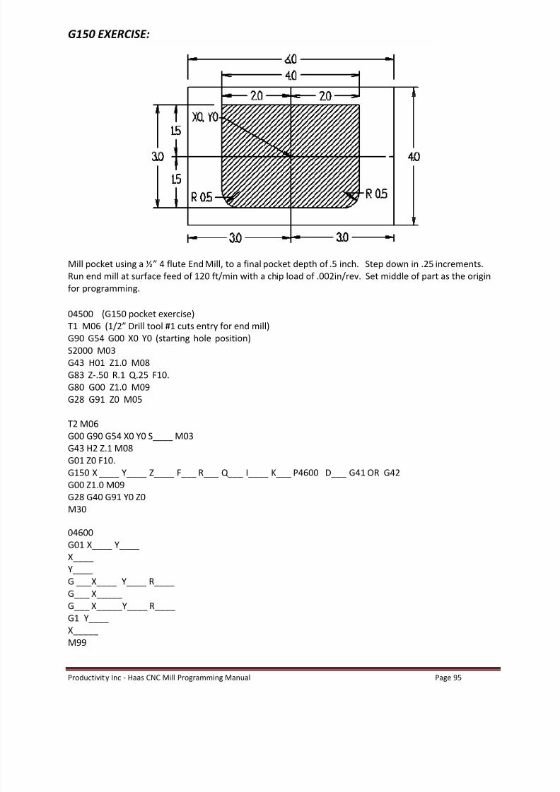
Mill pocket using a ½ 4 flute End Mill, to a final pocket depth of .5 inch. Step down in .25 increments.
Run end mill at surface feed of 120 ft/min with a chip load of .002in/rev. Set middle of part as the originfor programming.
04500 (G150 pocket exercise)T1 M06 (1/2 Drill tool #1 cuts entry for end mill)G90 G54 G00 X0 Y0 (starting hole position)S2000 M03G43 H01 Z1.0 M08G83 Z-.50 R.1 Q.25 F10.G80 G00 Z1.0 M09G28 G91 Z0 M05
T2 M06G00 G90 G54 X0 Y0 S____ M03G43 H2 Z.1 M08G01 Z0 F10.G150 X ____ Y____ Z____ F___ R___ Q___ I____ K___ P4600 D___ G41 OR G42G00 Z1.0 M09G28 G40 G91 Y0 Z0M30
04600G01 X____ Y____X____Y____G ___X____ Y____ R____G___ X_____G___ X_____Y____ R____G1 Y____X_____M99

8/20/2019 Haas-Mill-Programming-Manual.pdf
http://slidepdf.com/reader/full/haas-mill-programming-manualpdf 98/115
Productivity Inc - Haas CNC Mill Programming Manual Page 96
Engraving (G47)
G47 ENGRAVING GROUP 00
E = Plunge rate (units/min)F = Engraving feed rate (units/min)I = Angle of rotation (-360. to +360.), default is 0.J = Scaling factor in inches (minimum = 0.001 inches), default is 1.0 inchP = l for Sequential Serial Number Engraving
= 0 for Literal String EngravingR = Return planeX = X start of engravingY = Y start of engravingZ = Depth of cut
The text to engrave should be in the form of a comment on the same line as G47, with either a P1 or P0before it. P1 selects Sequential Serial Number Engraving and P0 selects Literal String Engraving.
SEQUENTIAL SERIAL NUMBER ENGRAVING
This method is used to engrave numbers on a series of parts, with the number being incremented by oneeach time. The '#' symbol is used to select the number of digits in the serial number. For example: G47
P1 (####) will limit the serial number to four digits.
The initial serial number can be either programmed or set manually. If it is programmed , for example:G47 P1 (1234) This code will set the initial serial number to "1234".
The initial serial number can also be set manually into a macro variable. The "MACROS" option does nothave to be enabled to do this. Macro variables are temporary storage locations for numbers. Macrovariable #599 is used to hold the initial serial number to be engraved. To set this variable, go to theCURNT COMDS page and press the PAGE DOWN key until the "Macro Variables" page appears. Then typein "599" and press the (DOWN ARROW). Now enter the desired initial serial number at the cursor andpress the WRITE key. For example, when macro variable #599 is set to "1234",
G47 P1 (####) will produce this: 1234
If the number in macro variable #599 has more characters than specified in the format string, only thequantity specified will be printed. For example, if #599 is set to"12345" and only four places are specifiedin the format string, only "2345" will be engraved.

8/20/2019 Haas-Mill-Programming-Manual.pdf
http://slidepdf.com/reader/full/haas-mill-programming-manualpdf 99/115
Productivity Inc - Haas CNC Mill Programming Manual Page 97
LITERAL STRING ENGRAVING
This method is used to engrave desired text on a part. The characters available for engraving are:
A..Za..z0..9! # & ( ) * + , / : ; < = > ? [ \ ] ^ { }
However, programs downloaded through the serial port or the floppy drive can take advantage ofcharacters not available on the mill keypad. For Literal String Engraving, the text should be in the form ofa comment on the same line as the P0 statement.
For example: G47 P0 (ENGRAVE THIS)will produce: ENGRAVE THIS
Note that P0 is used, instead of P1 , for Literal String Engraving.
8/20/2019 Haas-Mill-Programming-Manual.pdf
http://slidepdf.com/reader/full/haas-mill-programming-manualpdf 100/115
Productivity Inc - Haas CNC Mill Programming Manual Page 98
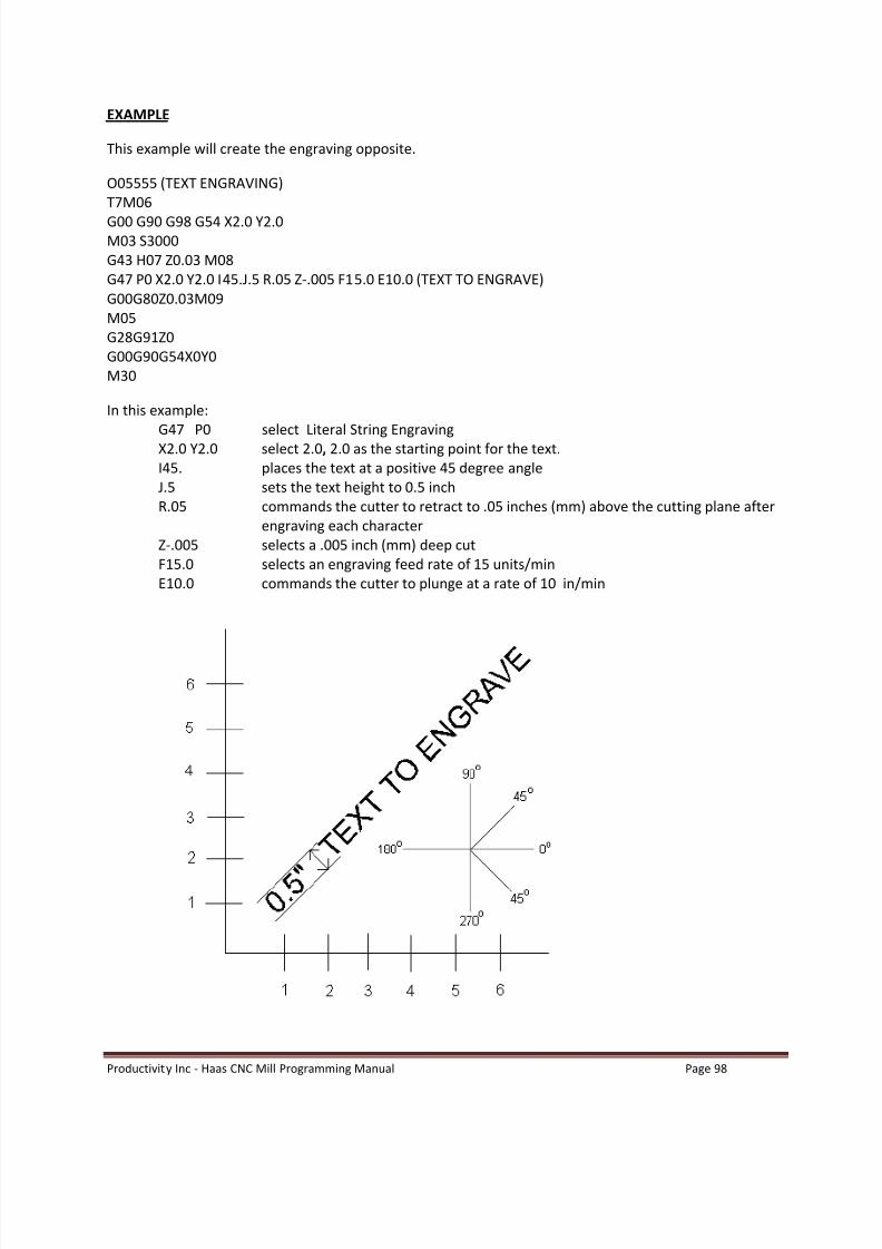
EXAMPLE
This example will create the engraving opposite.
O05555 (TEXT ENGRAVING)T7M06G00 G90 G98 G54 X2.0 Y2.0M03 S3000G43 H07 Z0.03 M08G47 P0 X2.0 Y2.0 I45.J.5 R.05 Z-.005 F15.0 E10.0 (TEXT TO ENGRAVE)G00G80Z0.03M09M05G28G91Z0G00G90G54X0Y0M30
In this example:G47 P0 select Literal String EngravingX2.0 Y2.0 select 2.0 , 2.0 as the starting point for the text.I45. places the text at a positive 45 degree angleJ.5 sets the text height to 0.5 inchR.05 commands the cutter to retract to .05 inches (mm) above the cutting plane after
engraving each characterZ-.005 selects a .005 inch (mm) deep cutF15.0 selects an engraving feed rate of 15 units/minE10.0 commands the cutter to plunge at a rate of 10 in/min

8/20/2019 Haas-Mill-Programming-Manual.pdf
http://slidepdf.com/reader/full/haas-mill-programming-manualpdf 101/115

8/20/2019 Haas-Mill-Programming-Manual.pdf
http://slidepdf.com/reader/full/haas-mill-programming-manualpdf 102/115
Productivity Inc - Haas CNC Mill Programming Manual Page 100

8/20/2019 Haas-Mill-Programming-Manual.pdf
http://slidepdf.com/reader/full/haas-mill-programming-manualpdf 103/115
Productivity Inc - Haas CNC Mill Programming Manual Page 101
Subroutines (Subprograms)
Subprograms are a very important part of CNC programming, however, they can make programmingbecome more complicated. This unit will give a brief introduction to subprograms and some of their basicapplications.
Objectives:
Upon completion of this unit, the student will:
1) Have a good working definition of a subprogram.
2) Understand the basic application and deployment of subprograms.
3) Know the differences between M97 (local) and M98 (separate) subprogram options.
4) Be able to integrate a subprogram into a standard program to achieve the desired results.
5) Looping subprograms with an L variable.*
*Denotes exposure only subject not covered in detail.

8/20/2019 Haas-Mill-Programming-Manual.pdf
http://slidepdf.com/reader/full/haas-mill-programming-manualpdf 104/115
Productivity Inc - Haas CNC Mill Programming Manual Page 102
Subroutines
A subprogram is a separate program called up by another program. The use of subprograms cansignificantly reduce the amount of programming on some parts. Subroutines allow the CNC programmerto define a series of commands that might be repeated several times in a program and, instead ofrepeating them many times, can be called up when needed.
A subroutine call is performed using an M97 or M98 and a Pnnnn . The P code command identifies the Oprogram number being used when executed with M98 or an N sequence number to identify the blockwhere a local subroutine starts when executed with M97.
Local subroutines are called with an M97 . This can be easier to use than the M98 because the subroutineis contained within the main program without the need to define a separate Onnnn program. With localsubroutines, you define an M30 for the end of your main program portion followed by a sequencenumber to define the beginning of your subroutine.
This subroutine call causes the blocks in the subroutine to be executed as if they were included in themain program. To return back to the main program, you need to end the subroutines with an M99 , whichsends it back to the next line after the subroutine call in the main program.
Another important feature of a subroutine call is that the M98 block may also include an L (loop) orrepeat count. If there is an Ln with the subroutine call, it is repeated that number of times before themain program continues with the next block.
The most common use of subroutines is in the definition of a series of holes, which may need to be centerdrilled, peck drilled, taped, and/or chamfered. If a subroutine is defined that consists only of the X-Yposition of the holes, the main program can define the canned cycles and the hole locations can be calledup in the subroutine to do each of the tool operations. Thus, the X-Y positions can be entered only onceand used several times for each tool.
O0100 (main program using subroutines);T01 M06 (center drill);G90 G54 G00 X0.5 Y0.5;S2000 M03;G43 Z0.5 H01;G81 Z-0.3 R0.1 F15. (define canned cycle);M98 P0200 (call subroutine O200);
T02 M06 (peck drill);G90 G54 G00 X0. 5Y 0.5;S1500 M03;G43 Z0.5 H02;
G83 Z-1. R0.1 Q.100 F10. (define canned cycle);M98 P0200 (call subroutine O200);
T03 M06 (1/4 20 tap);G90 G54 G00 X.5 Y.5;S400 (G84 will turn spindle on, no M03 is needed);G43 Z1. H03;G84 Z-1. R.1 F10. (define canned cycle);M98 P0200 (call subroutine O200);

8/20/2019 Haas-Mill-Programming-Manual.pdf
http://slidepdf.com/reader/full/haas-mill-programming-manualpdf 105/115
Productivity Inc - Haas CNC Mill Programming Manual Page 103
T04 M06 (chamfer);G90 G54 G00 X.5 Y.5;S2500 M03;G43 Z0.1 H04;G81 Z-0.1 R0.1 F20. (define canned cycle);M98 P0200 (call subroutine O200);G28 Y0.;M30 (end of main program);(SUBROUTINE) (LISTING ALL THE HOLE POSITIONS)
O0200X1.5;X2.5;X2. Y1.;X1.;X.5 Y1.5;X1.5;X2.5;G80 Z1.0 M09;G28 G91 Z0. M05;M99 (end of subroutine);
To return back to the main program, you need to end the subroutines with an M99, which sends it back to the next line afterthe subroutine call in the main program.
O0300 (example using a local subroutine);T1 M06;G90 G54 G00 X.5 Y.5;S2000 M03;G43 Z1.0 H01;G81 Z-0.1 R0.1 F20 (define canned cycle);M97 P0500 (call local subroutine using sequence N#);
T02 M06 (peck drill);G90 G54 G00 X.5 Y.5;S1000 M03;G43 Z1. H02 M08;G83 R0.1 Z-1. F10. (define canned cycle);M97 P0500 (call local subroutine using sequence number 500);
G28 Y0.;M30 (end of main program);
N0500 (local subroutine example listing all hole positions);X1.5;X2.5;Y1. X2.;X1.;X0.5 Y1.5;X1.5;X2.5;G80 G00 Z1. M09;G91 G28 Z0. M05;M99 (end of local subroutine);

8/20/2019 Haas-Mill-Programming-Manual.pdf
http://slidepdf.com/reader/full/haas-mill-programming-manualpdf 106/115
Productivity Inc - Haas CNC Mill Programming Manual Page 104
Exercises
Canned Cycle Exercise #1
TOOL NUMBER ONE
· ½ Diameter Center/Spot Drill (use G81 canned cycle) · surface speed (SFM) = 190· feed inch/rev = .0035
TOOL NUMBER TWO
· ¼ Diameter Drill (use G83 canned cycle)· surface speed (SFM) = 190· feed inch/rev = .006
TOOL NUMBER THREE
· 3/8 Diameter 4 flute End Mill (use G82 canned cycle)· surface speed (SFM) = 190· inch/rev/tooth = .003

8/20/2019 Haas-Mill-Programming-Manual.pdf
http://slidepdf.com/reader/full/haas-mill-programming-manualpdf 107/115
Productivity Inc - Haas CNC Mill Programming Manual Page 105
O0068 (CANNED CYCLE EXERCISE)
N1 (1/2 DIA. SPOT DRILL)G53 Z0 G49T__ M__G__ G__ G__ X.__ Y.__ M__S____G__ Z._ H__ M__G__ Z-.___ R__ F__ L_M__ P___M_N2 (1/4 DIA. DRILL)T_ M__G__ G__ G__ X___ Y___ M__ S____G__ Z___ H__ M__G__ Z-___ R__ F__ Q.____ L_M__ P____M__N3 (3/8 DIA. ENDMILL)T__ M__G__ G__ G__ X___ Y___ M__ S____G__ Z___ H__ M__G__ Z-___ R___ F___ P___ L_M__ P____G__ G__ Y_M__
N1000 (HOLE SUBROUTINE)X___ Y___Y___X___Y___G__ G__ Z___ M___G__ G__ Z___M__

8/20/2019 Haas-Mill-Programming-Manual.pdf
http://slidepdf.com/reader/full/haas-mill-programming-manualpdf 108/115
Productivity Inc - Haas CNC Mill Programming Manual Page 106
Canned Cycle Exercise #2
TOOL NUMBER ONE
· 5/8 Diameter Spot Drill (use G81 canned cycle) · surface speed (SFM) = 190· feed in/rev. = .0035
TOOL NUMBER TWO
· 27/64 Diameter Drill (use G73 canned cycle)· surface speed (SFM) = 190· feed in/rev = .006
TOOL NUMBER THREE
· ½-13 Tap (use G84 canned cycle)· 600 RPM
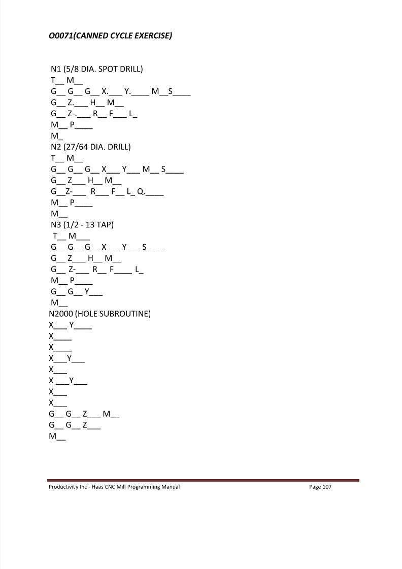
8/20/2019 Haas-Mill-Programming-Manual.pdf
http://slidepdf.com/reader/full/haas-mill-programming-manualpdf 109/115

8/20/2019 Haas-Mill-Programming-Manual.pdf
http://slidepdf.com/reader/full/haas-mill-programming-manualpdf 110/115
Productivity Inc - Haas CNC Mill Programming Manual Page 108
FINAL EXERCISES
Tool #1 - 2.00 diameter 4 flute end mill finish diamond shape contour 1 pass at .3 depth275 SFM - .005 inch/rev per tooth
Tool #2 1 ¾ diameter insert drill rough 1.800 circular pocket at .480 depth250 SFM - .0075 inch/rev
Tool #3 5/8 diameter 4 flute end mill finish mill 1.800 diameter circular pocket .5 depth220 SFM - .0045 inch/rev per tooth
Tool #4 ½ diameter spot drill drill 6 holes .2 depth200 SFM - .005 inch/rev
Tool #5
5/16 diameter drill (6) holes through200 SFM - .005 inch/rev
Tool #6 3/8 16 tap (6) holes throughTap at 600 RPM and your machine has rigid tapping
Tool #7- Engrave your name anywhere on the part using a1/8 inch ball end millEngrave at 200ft/min - .001 in/rev
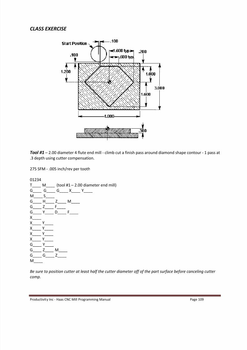
8/20/2019 Haas-Mill-Programming-Manual.pdf
http://slidepdf.com/reader/full/haas-mill-programming-manualpdf 111/115
Productivity Inc - Haas CNC Mill Programming Manual Page 109
CLASS EXERCISE
Tool #1 2.00 diameter 4 flute end mill - climb cut a finish pass around diamond shape contour - 1 pass at.3 depth using cutter compensation.
275 SFM - .005 inch/rev per tooth
01234T____ M____ (tool #1 2.00 diameter end mill)G____ G____ G____ X____ Y____M____ S____G____ H____ Z____ M____G____ Z____ F____G____ Y____ D____ F____X____X____ Y____X____ Y____X____ Y____X____ Y____
G____ Y____G____ Z____ M____G____ G____ Z____M____
Be sure to position cutter at least half the cutter diameter off of the part surface before canceling cuttercomp.
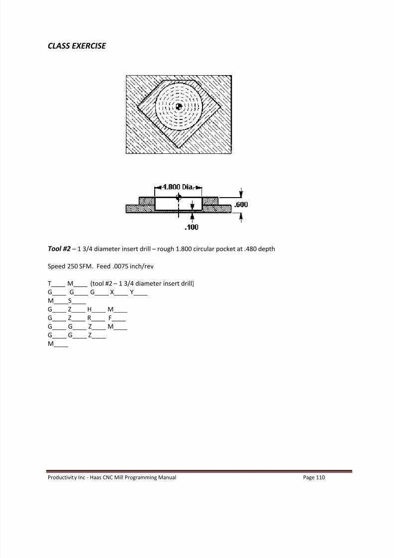
8/20/2019 Haas-Mill-Programming-Manual.pdf
http://slidepdf.com/reader/full/haas-mill-programming-manualpdf 112/115
Productivity Inc - Haas CNC Mill Programming Manual Page 110
CLASS EXERCISE
Tool #2 1 3/4 diameter insert drill rough 1.800 circular pocket at .480 depth
Speed 250 SFM. Feed .0075 inch/rev
T____ M____ (tool #2 1 3/4 diameter insert drill)
G____ G____ G____ X____ Y____M____S____G____ Z____ H____ M____G____ Z____ R____ F____G____ G____ Z____ M____G____ G____ Z____M____

8/20/2019 Haas-Mill-Programming-Manual.pdf
http://slidepdf.com/reader/full/haas-mill-programming-manualpdf 113/115
Productivity Inc - Haas CNC Mill Programming Manual Page 111
CLASS EXERCISE
Tool #3 5/8 diameter 4 flute end mill mill a 1.800 diameter circular pocket .5 depth
220 SFM - .0045 inch/rev per tooth
T____ M____ (tool #3 5/8 diameter 4 flute end mill)G____ G____ G____ X____ Y____M____S____G____ Z____ H____ M____G____ I____ K____ Q____ Z____ D____ F____G____ Z____ M____G____ G____ Z____M____

8/20/2019 Haas-Mill-Programming-Manual.pdf
http://slidepdf.com/reader/full/haas-mill-programming-manualpdf 114/115
Productivity Inc - Haas CNC Mill Programming Manual Page 112
CLASS EXERCISE
Tool #4 1/2 diameter spot drill spot drill 6 holes .2 depth200 SFM - .005 inch/rev
Tool #5 5/16 diameter drill drill 6 holes through200 SFM - .005 inch/rev
Tool #6 3/8 16 Tap (6) holes through tap at 600 RPM
Your machine has rigid tapping
T____ M____ (tool #4 1/2 diameter spot drill)G____ G____ G____ X____ Y____M____ S____G____ Z____ H____ M____G____ G____ Z____ R____ F____ L____M____ P____G____ G____ Z____M____
T____ M____ (tool #5 5/16 diameter drill)G____ G____ G____ X____ Y____S____ M____G____ Z____ H____ M____G____ G____ Z____ R____ F____ L____M____ P____G____ G____ Z____M____

8/20/2019 Haas-Mill-Programming-Manual.pdf
http://slidepdf.com/reader/full/haas-mill-programming-manualpdf 115/115
T____ M____ (tool #6 3/8-16 tap)G____ G____ G____ X____ Y____S____G____ Z____ H____ M____G____ G____ Z____ R____ F____ L___M____ P____G____ G____ Z____M____
T____M____ (tool #7 1/8 ball end mill)G____ G____ G____ X____ Y____M___ S____G___ H___ Z____ M____G____ P___ X____ Y____I____J____ R____ Z____ F____ E____ (YOUR NAME)G____G____Z____M____M____G____G____Z____
G____G____Y____M___
(Subprogram)
O1000 (subprogram)X-.___ Y-__.__G__ __ X-___ Y-.___Y.____X__.__G__ __ Y-.____X.____ Y-__.__G__ G__ Z__M__M__ __