ha 70/140h-8 ha 106 7/14 mpa double acting … · 70/140h-8 7/14 mpa double acting hydraulic...
TRANSCRIPT

7/14 MPa Double Acting Hydraulic Cylinder70/140H-870/140H-8 General Hydraulic Cylinders
106HA
7/14 MPa Double Acting Hydraulic Cylinder 70/140H-8General H
ydraulic Cylinders
70/140H-8
107HA
Nominal pressure
Maximum allowable pressure
Proof test pressure
Minimum operating pressure
Working speed range
Structure of cushioning
Adaptable fluid
Tolerance for thread
Tolerance of stroke
Tube material
Mounting style
Accessories
High-performance cushion built in hydraulic cylinders
Standard Specifications
General purpose type, cutting oil proof typeType
Petroleum-based fluid(When using another fluid, refer to the table of fluid adaptability.)
Cap side:0.3 MPa or lessRod side:(A) 0.6 MPa or less
(B) 0.45 MPa or less:(C) 0.4 MPa or less
Working temperature range (ambient temperature)
aPM41aPM7
f32 to f63:8 to 400mm/s f80 to f125:8 to 300mm/s f140 to f250:8 to 200mm/s
Metal fitting system
JIS 6g/6H
SD・LA・LB・LC・FA・FB・FC・FD・FK・FE・FY・FZ・CA・CB・CS・TA・TC
Cap side:9 MPaRod side:(A) 15 MPa
Cap side:18 MPa
(B) 13.5 MPa(C) 11 MPa
Rod side:(A) 18 MPa(B) 18 MPa(C) 14 MPa
● Rod eye (T-end), rod eye with spherical bearing (S-end), rod clevis (Y-end) with pin, lock nutFloating joint (F-end) : Only 7 MPa typeBoots : Only general purpose type Standard : Nylon tarpaulin Semi-standard : Chloroprene, Conex
●
●
Standard type …………● Carbon steel for machine structural useSwitch Set ………………
Standard type ・・・・・・・・・・・・・・ -10 to +80℃(Notes)Switch Set AX type WR/WS type
・・・・・・・・ -10 to +70℃・・・・ -10 to +60℃
(No freezing)
0 to 100mm 101 to 250mm 0251 to 630mm
631 to 1000mm 1001 to 1600mm 1601 to 2000mm
+0.8 0+1.4 0
+1.0 0+1.6 0
+1.25 0+1.8 0
SD・LA・LC・FC・FD・FE・FK・FY・FZ・CA・CB・CS・TA・TC
● Double acting hydraulic cylinders for 7/14 MPa with bore from 32 mm to 250 mm.
● High-performance cushion reduces a shock at stroke-end.
● Newly designed cushion valve allows easy cushion adjustment.
● The drop prevention mechanism and looseness preventive lock nut have been adopted as safety measures for the cushion valve.
● Wide variety of new-type small sensors for better maintainability.
Nominal pressurePressure given to a cylinder for convenience of naming.It is not always the same as the working pressure (rated pressure) that guarantees performance under the specified conditions.
Maximum allowable pressureThe maximum allowable pressure generated in a cylinder. (surge pressure, etc.)
Proof test pressureTest pressure against which a cylinder can withstand without unreliable performance at the return to nominal pressure.
Minimum operating pressureThe minimum pressure that a cylinder placed horizontally without a load can work.
Terminologies
Notes) ● The hydraulic pressure generated in a cylinder due to the inertia of load must be lower than the maximum allowable pressure.
● The working temperature range depends on the seal material. For details, refer to the selection materials at the beginning of this catalog.
● The standard type cylinders can be used up to the working temperature range shown in the selection materials by using seal material 6, HNBR.
● In case that the lock nut is attached to the piston rod end thread part, increase the thread length (dimension A).
● The FE style in the mounting style column can be used only for the rod A.
● For the internal structure, refer to the sectional drawings at the end of this catalog.
● Conex, material of the boots, is the registered trademark of Teijin Limited.
● The mounting style LB cylinders with rod A have bores of up to 125 mm.
● Stainless steel
10.5 MPa 21 MPa
Product Lineup
Double acting single rod
Series Variations Type
Standard Stroke Range Unit: mm
Bore
f32 to f50
f63・f80
f100 to f140
f150 to f250
Standard type
1200
1600
2000
2000
Switch Set
1200
1600
2000
―
L LCushion Stroke Length Unit: mm
Cushion ring length L
Cushion ring parallel part length ℓ
R side
H side
f40 to f63
f80 to f125
f140 to f160
f180 to f224
f250
Bore
25
23
25
25
30
40
45
7
7
7
8
12
20
25
f40 f50 f80 f100 f125 f140 f150 f160 f180 f200f224f250f63f32
Standard type70/140H-8
Switch Set70/140H-8R
70/140H-8D
70/140H-8RD
70/140HW-8
70/140HW-8R
Double acting single rod
Double acting double rod
Double acting double rod
General purpose type
Cutting oil proof type
Rod B
Rod B
Rod B
Rod B
Rod B
Rod B
Rod C
Rod C
Rod C
Rod C
Rod C
Rod A
Rod C
Rod A
Unit: mm
Rod dia.
f32
Double acting single rod
Double acting single rod
Standard type
Standard type
Switch Set
Switch Set
Notes) ● When using a sensor, use a Switch Set Cylinder. ● No sensor can be mounted onto the standard type cylinder.
● The above strokes indicate the maximum available strokes for the standard type. Contact us for longer strokes.
● For the rod buckling, check with the buckling chart in the selection materials. Contact us for longer strokes.
● The cushion stroke lengths in case of cylinders used up to the stroke end.
● In the case that a cylinder is not used up to the stroke end, and it is stopped 5 mm or more before the stroke end, the cushioning effect will be weakened. In such a case, consult us.

7/14 MPa Double Acting Hydraulic Cylinder70/140H-870/140H-8 General Hydraulic Cylinders
108HA
7/14 MPa Double Acting Hydraulic Cylinder 70/140H-8General H
ydraulic Cylinders
70/140H-8
109HA
General Purpose Type Semi-standard specification
Seal ma
terial❷
Type❶
Cushion
ing❻
Cylinder bore❹
Mounting s
tyle❸
Stroke❼
Rod type❺
The item enclosed by broken line needs not to be entered, if unnecessary.
Port position❾
Rod en
d attac
hment13
Boots15
Cushio
n valve
positi
on10
Lock nu
t14
Sensor symb
ol11
Sensor quantity12
140HW-8 6 LA 80 B B 200 - A B C 2 -
140HW-8R 6 LA 80 B B 200 - A B 5 2 -
Nitrile rubber (φ32 to φ250)Urethane rubber (φ32 to φ160)Fluorocarbon (φ32 to φ250)HNBR (φ32 to φ160)Slipper seal (φ32 to φ100)
Mounting style
Cylinder stroke (mm)
Double acting single rod● For 7 MPa 70H-8 :Standard type 70H-8R :Switch Set● For 14 MPa 140H-8 :Standard type 140H-8R :Switch Set
Double acting double rod● For 7 MPa 70H-8D :Standard type 70H-8RD :Switch Set● For 14 MPa 140H-8D :Standard type 140H-8RD:Switch Set
!
Rod AStandard type:φ40 to φ160Switch Set: φ40 to φ125Rod B/CStandard type:φ32 to φ250Switch Set: φ32 to φ140
● Switch Set
Cutting Oil Proof Type
HNBR
Cylinder bore (mm) φ32 to φ125
Double acting single rod● For 7 MPa 70HW-8 :Standard type 70HW-8R :Switch Set● For 14 MPa 140HW-8 :Standard type 140HW-8R:Switch Set
Nylon tarpaulinChloropreneConex
NJNJNJK
Rod eye (T-end)Rod eye with spherical bearing (S-end)Rod clevis (Y-end)Floating joint (F-end) (for 7 MPa)
With lock nut
Rod ARod BRod C
Note) The available minimum dia. of the rod C is φ40.
With cushions on both endsWith cushion on the rod sideWith cushion on the cap sideNo cushion
140H-8R 2 LA 80 B B 200 - A B AH 2 - -
140H-8 2 LA 80 B B 200 - A B C 2 - -
T L J
T L J
Notes) The material of Slipper seal is nitrile rubber except for the piston. Switch Set Cylinders are not provided with Slipper seals.
T L
T L
G
G
G
G
● Standard type
WR505(w/ 5 m cord)WR505F(w/ 5 m cord/flexible tube attached)WR515(w/ 5 m cord)/cord type)AX205W(w/ 5 m cord)AZ205W(w/ 5 m cord)WS215-1(w/ 5 m cord)WS215-1F(w/ 5 m cord/flexible tube attached)WS225-1(w/ 5 m cord/cord type)
Reed sensor
Solid state sensor RA
RB
Port type❽
● Standard type
● Switch Set
□□□□
□□□
A
□T
□L
□S
□Y□F
BC
□□□
BRH□N
□
Sensor symbolNote) Select applicable sensors
out of the Sensor List.
Sensor quantity(1, 2, to n)
●Notes on ordering Switch Set●
●
When no sensor is required, specify 0 for the sensor symbol 11 and the sensor quantity 12.Sensors are not mounted on cylinders at delivery.
Sensor symbol(A, B, C, D)
Cushion valve position(A, B, C, D, 0)
G thread (order made) (order made)□
Rc threadGNPT thread (order made)□N
●For the details of types other than the above, refer to the specifications of the general purpose type.●These types of cylinders with boots are not available.
Notes)
12368
576
243
Sensor List
B contact output
5 to 300mAAC/DC:90 to 240V
AF AG AH AJ AE AK AL AP AR AS AT AN AU AW 5 7 6 AM AY S BE BF CE CF CH CJ BM BN CM CN RA RB RE RF 2 4 3
AX101CE AX105CE AX111CE AX115CE AX125CE AX11ACE AX11BCE AZ101CE AZ105CE AZ111CE AZ115CE AZ125CE AZ11ACE AZ11BCEWR505 WR505F WR515 AX135CE AZ135CE SR405 AX201CE-1 AX205CE-1 AX211CE-1 AX215CE-1 AX21CCE-1 AX21DCE-1 AZ201CE-1 AZ205CE-1 AZ211CE-1 AZ215CE-1 AX205WCE AZ205WCE AX215WCEAZ215WCEWS215-1 WS215-1F WS225-1
1.5m 5m 1.5m 5m 5m 0.5m 0.5m 1.5m 5m 1.5m 5m 5m 0.5m 0.5m 5m 5m 5m 5m 5m 5m 1.5m 5m 1.5m 5m 0.5m 1m 1.5m 5m 1.5m 5m 5m 5m 5m 5m 5m 5m 5m
DC:1.5W AC:2VA
DC:1.5W AC:2VA
DC:5 to 30V 5 to 40mA ―
AC:5 to 120V DC:5 to 30V
5 to 20mA 5 to 40mA
2VA 1.5W
2VA 1.5W
5 to 20mA 5 to 40mA
AC:5 to 120V DC:5 to 30V
None
Provided
Provided
Provided
None
Provided
Provided
Provided
Provided
Provided
Provided
Provided
None
None
None
None
None
DC:5 to 50V AC:5 to 120V
DC:3 to 40mA AC:3 to 20mA
DC:1.5W AC:2VA
DC:10 to 30V 5 to 20mA ―
DC:5 to 30V AC:5 to 120V
DC: 30 V or lessAC: 120 V or less
DC: 40 mA or lessAD: 20 mA or less
DC: 30 V or lessAC: 120 V or less
DC: 40 mA or lessAD: 20 mA or less
DC:5 to 40mA AC:5 to 20mA
DC:5 to 30V AC:5 to 120V
DC:5 to 40mA AC:5 to 20mA
CT AX211CE-1CU AX215CE-1CV AX21BCE-1CW AZ211CE-1CX AZ215CE-1CY AZ21BCE-1
1.5m5m0.5m1.5m5m0.5m
― 5 to 40mA
DC:5 to 30V5 to 40mA
5 to 20mA―
DC:5 to 30V
AC:80 to 220V 2 to 300mA Neon lamp (Lights when not sensing)30VA
Type Sensor symbol Load voltage range Load current range Max. switching capacity
Protective circuit Indicating lamp Wiring method Cord length Applicable load
Reed sensor
Solid state sensor
Solid state
sensor
Solid state sensor
Cutting oil
proof type
LED (Lights in red when sensing)
LED (Lights in red when sensing)
LED (Lights in red when sensing)
LED (Lights in red when sensing)
LED (Lights in red when sensing)
LED (Lights in red when sensing)
LED (Lights in red when sensing)
LED (Lights in red when sensing)
LED(2-LED type in red/green)
LED(2-LED type in red/green)
LED(2-LED type in red/green)
LED(2-LED type in red/green)
LED(2-LED type in red/green)
LED(Lights in red
when not sensing)
0.3 mm², 2-core, outer dia. φ4 mmRear wiring
0.3 mm², 2-core, outer dia. φ4 mmRear wiring
0.3 mm², 2-core, outer dia. φ4 mmRear wiring
0.3 mm², 2-core, outer dia. φ4 mmRear wiring
0.3 mm², 2-core, outer dia. φ4 mmRear wiring
0.3 mm², 2-core, outer dia. φ4 mmUpper wiring
0.3 mm², 2-core, outer dia. φ4 mmUpper wiring
0.3 mm², 2-core, outer dia. φ4 mmUpper wiring
4-pin connector type, Rear wiring
4-pin connector type, Rear wiring
4-pin connector type, Upper wiring
0.3 mm², 2-core, outer dia.φ4 mm, Rear wiring
0.5 mm², 2-core, outer dia.φ6 mm, Rear wiring
0.3 mm², 2-core, outer dia.φ4 mm, Upper wiring
0.3 mm², 2-core, outer dia.φ4 mm, Rear wiring
0.3 mm², 2-core, outer dia.φ4 mm, Upper wiring
0.3 mm², 2-core, outer dia.φ4 mm, Rear wiring
0.3 mm², 2-core, outer dia.φ4 mm, Upper wiring
4-pin connector type,Upper wiring
4-pin connector type,Rear wiring
Small relay, programmable controller
Small relay, programmable controller
Notes) ● For the sensors without a protective circuit, be sure to provide a protective circuit (SK-100) with the load when using any induction load (relay, etc.).● The output logic of AX and AZ135CE is B contact. When the piston is detected, the sensor contact turns off (the lamp turns on).● For the details of sensors, be sure to read the sensor specifications at the end of this catalog.● WR and WS type sensors are cutting oil proof. (Bores from 32 mm to 125 mm)● Sensor SR405 can be mounted only to cylinders with bores from 32 mm to 125 mm.● We recommend AND Unit (AU series) for multiple sensors connected in series. For details, refer to AND Unit at the end of this catalog.
● Standard type AX type (rear wiring)
● Cutting oil proof type WR/WS type sensor
● When ordering the cutting oil proof type sensors, WR and WS types, please be carefully the followingnotification.□ WR505□ WS215-1
The sensor and straight box connector (F-SB) are combined (the flexible tube (F-0.5: 4.8 m) is required).
□ WR505F□ WS215-1F
The flexible tube (F-0.5: 4.8 m) is attached to the sensor and straight box connector (F-SB).
AZ type (upper wiring)
5
2
7
4
●How to order

7/14 MPa Double Acting Hydraulic Cylinder70/140H-870/140H-8 General Hydraulic Cylinders
110HA
7/14 MPa Double Acting Hydraulic Cylinder 70/140H-8General H
ydraulic Cylinders
70/140H-8
111HA
Cushion valve and air vent positions depending on cylinder bore (for rod A only)
Air vent Air ventCushion valve Cushion valve
Bore f63, f80, f125, f160
Standard Stroke Range
●
●
Adaptability of Fluid to Seal Material
Seal material
○
△
○
◎
○
△
○
◎
×
×
○
×
○
×
×
◎
○
◎
○
○
Boref40, f50, f100, f140, f150
Bore
f32 to f50
f63・f80
f100 to f140
f150 to f250
Standard type
1200
1600
2000
2000
Switch Set
1200
1600
2000
―
Cutting Oil Proof Type/Adaptability of cutting oil to seal material
○: Applicable ×: Inapplicable
Nonaqueous cutting oil
○
Type 1 Type 2Aqueous cutting oil
× ○
For the working temperature range of seal materials, refer to the selection materials at the beginning of this catalog.
Port, cushion and air vent positions for LA style
Port position Ⓐ Port position Ⓑ
Port position Ⓒ Port position Ⓓ
A
B B
B B
C C
C C
D D
D D
A
A A
Mounting styleSD SD style (basic style)
FB FB style (cap rectangular flange) (for 7 MPa)
CB CB style (cap clevis)Cap clevis mounting according to former JIS
FD FD style (cap square flange)LA LA style (side lugs)
FY FY style (rod rectangular flange)FE FE style (for rod A)
FK FK style (intermediate flange)
CA CA style (cap eye)Cap eye mounting according to former JIS
LB LB style (end angles)(for 7MPa)
FZ FZ style (cap rectangular flange)
CS CS style (cap eye with spherical bearing)FA FA style (rod rectangular flange) (for 7 MPa) (for rod B/C)
FC FC style (rod square flange) (for rod B/C)
Note) The mounting styles for 7 MPa cannot be used at a pressure exceeding 7 MPa as a rule. For the usage, consult us.
LC LC style (end angles with rib) TC TC style (intermediate trunnion)
TA TA style (rod trunnion)
Adaptable fluid
Water in oil fluid
Oil in water fluid
Phosphate ester fluid
Water-glycol fluid
Petroleum-based fluid
□Nitrile rubber
□Urethane rubber
□Fluorocarbon
□HNBR
1
2
3
6
□HNBR6
Notes)1. ◎○: Applicable ×: Inapplicable Consult us before using the △-marked items. 2. The ◎-marked items are recommended seal materials in case of giving the first priority to abrasion resistance.
Seal material
The above strokes indicate the maximum available strokes for the standard type. For the rod buckling, check with the buckling chart in the selection materials. Contact us for longer strokes.If a cylinder with a bore of 63 to 160 mm should be used with a stroke exceeding the above values (up to 3000), select one from 140L-1 Series.However, the series differs from H-8 Series in external dimensions.
Standard specifications●●With cushions on both endsPort position Ⓐ, cushion valve position Ⓑ
●●
●
●●●
With bootsMagnetic proximity sensors, WR and WS typesNote) The WR and WS types are the standard types for the cutting oil proof models.Change in TC accessory position (dimensional symbol: PH)Change in dimension PN of the FK stylePlated cylinder tube (hard chrome plating thickness: 0.02 mm)Change in piston rod end (dimensional symbol: W, A, KK)Refer to the “Change of Rod End Shape” page.
Semi-standard range
Port position(A, B, C, D)
Cushion valve position(A, B, C, D, 0)
A
BD
C
Unit: mm
Mounting style
Sensor quantity
Sensor type
φ32
φ40
φ50
φ63
φ80
φ100
φ125
φ140
Sensor Mountable Minimum Stroke
Boremm
Styles other than TC
20
20
20
20
20
20
20
20
With one sensor
45(35)
45(35)40
(30)
35(25)35
(25)
40(30)
40(30)
45(35)
40(30)40
(25)
25
25
25
25
25
25
25
With two sensors
45(35)
45(35)40
(30)
35(25)35
(25)
40(30)
40(30)
45(35)
40(30)40
(25)
TC style
50
50
50
60
60
65
70
With one sensor
70(60)70
(60)70
(60)
85(75)90
(80)
110
115
115
125
130
135
150
With two sensors
85(75)
85(75)
75(65)75
(65)75
(65)
95(85)95
(85)
155(135)155
(135)155
(135)170
(150)170
(150)175
(150)185
(160)
165(145)165
(145)165
(145)175
(155)175
(155)190
(170)195
(170)
- - 25 - - 95 - - 175 - -
Change of port and cushion valve positionsThe standard port position is Ⓐ, and the standard cushion valve position is Ⓑ.When modifying the positions, enter the symbol shown inthe dimensional drawings.
Example) 70H-8R 2SD80BB100- B C AH2
● For the TA style, the standard port position and cushion valve position are Ⓐ and Ⓒ on the rod side and Ⓐ and Ⓑ on the cap side.In case that the cushion is not equipped, the cushion valve position is “0”.
●
FF
AE
DE
Port G (ISO 1179-1) or NPT(order made)
For a port G thread type cylinder, make an order in accordance with the following procedure.(Example) 70H-8 2LA50BB100-G A BG: Port G thread type N: NPT thread typePort positionCushion valve position
Bore
f32f40f50f63f80f100f125f140f150f160
AE12121414161618181818
f25.5f25.5f30f30f36.9f36.9f46.1f46.1f46.1f46.1
G3/8G3/8G1/2G1/2G3/4G3/4G1G1G1G1
DE FF
Thread Dimension Table Unit: mmG thread
NPT thread
NPT3/8NPT3/8NPT1/2NPT1/2NPT3/4NPT3/4NPT1NPT1NPT1NPT1
Delivery of rod end attachment (T-end or Y-end)
AX type AX type AX type AX typeWR type WS type WR type WS type WR type WS type WR type WS type
Notes)● For the TC style with one sensor, the cylinder strokes when the TC accessory is positionedat the place other than the center (as shown in the right figures) are shown in the table.
● For the minimum dimension PH of TC style for mounting sensor, refer to the dimensional drawings of TC style.
● The parenthesized values in the WR and WS type columns are the minimum strokes in case of WR515 or WS225.
There are check valves on two sides out of the four outer sides of cap and rod cover except the port and cushion sides. The check valve is concurrently used with air vent.
A delivery method for a cylinder provided with a lock nut and a rod end attachment differs from that for a cylinder provided with a rod end attachment only (without a lock nut). For details, refer to the dimensional drawings of rod end attachments.
Notes)

7/14 MPa Double Acting Hydraulic Cylinder70/140H-870/140H-8 General Hydraulic Cylinders
112HA
7/14 MPa Double Acting Hydraulic Cylinder 70/140H-8General H
ydraulic Cylinders
70/140H-8
113HA
Weight Table/General purpose type and cutting oil proof type Unit: kg
Calculation formula
Calculation example
BABCABCABCABCABCABCABCABCABCBCBCBCBC
3.33.83.53.45.55.04.99.17.97.618.016.215.529.626.024.949.242.942.567.559.656.077.969.667.993.084.379.9115.1108.5155.2147.3203.8190.9283.7264.1
4.1-4.44.3-6.46.2-10.29.8-20.319.4-32.731.1-53.652.7-73.969.6-86.583.6-114.699.1149.9140.1201.4189.0268.7247.7374.5344.1
0.0060.0130.0110.0100.0170.0140.0120.0240.0190.0170.0390.0320.0270.0600.0480.0420.0960.0770.0650.1220.1000.0850.1480.1180.1010.1480.1210.1020.1790.1570.2200.1920.2680.2340.3330.290
0.008-0.0140.012-0.0190.014-0.0270.022-0.0450.035-0.0670.055-0.1070.084-0.1400.111-0.1620.127-0.1710.1320.2120.1680.2640.2090.3310.2620.4110.324
0.3
0.5
0.9
1.0
1.8
2.1
3.2
3.8
4.8
5.4
7.9
11.4
12.7
18.3
0.3
0.5
0.7
1.2
2.0
2.9
5.5
7.7
9.6
10.0
13.8
21.0
32.0
46.7
0.1-
0.2
-
0.7
-
1.0
-
1.1
-
1.8
-
2.9
-
3.2
-
4.9
-
5.3
7.7
10.6
11.6
17.5
0.6
0.7
1.2
1.8
3.0
4.8
8.4
11.1
13.7
16.5
22.7
31.6
41.5
55.1
0.6
0.7
1.5
2.2
2.8
4.6
8.0
9.2
16.6
19.0
25.0
28.8
33.2
48.2
0.9
1.1
2.0
3.0
4.7
7.4
13.0
17.1
22.4
25.2
33.6
48.7
63.1
88.3
- 0.9
-
1.5
-
2.3
-
3.9
-
6.6
-
11.4
-
14.9
-
17.9
-
21.5
-
-
-
-
-
0.2
0.3
1.1
1.6
2.1
3.9
6.2
8.2
10.7
11.3
17.5
22.6
30.6
42.5
0.7
0.8
1.6
2.4
4.0
6.9
12.1
16.1
19.5
22.5
32.5
43.6
60.5
80.1
0.4
0.5
1.0
2.0
3.0
5.5
9.9
16.7
18.2
22.9
33.8
51.4
65.6
74.5
0.5
0.6
1.2
2.6
3.6
6.7
12.1
21.0
26.8
28.4
42.9
65.4
82.7
91.6
0.1
0.1
0.4
0.6
0.6
1.0
2.1
4.1
4.6
5.2
18.617.924.323.436.535.127.026.1
0.5
0.6
1.0
1.2
2.1
3.8
6.2
11.1
10.9
14.8
19.4
27.2
36.5
43.3
φ32
φ40
φ50
φ63
φ80
φ100
φ125
φ140
φ150
φ160
φ180
φ200
φ224
φ250
Bore (mm)
Rod type
LA LB FA FB FC FD FE FY FZ CA CB TA TC
Basic weight (SD style)
Additional weight per mm of stroke
Standard typeSwitch Set
Standard typeSwitch Set
Double rod type
Double rod type
Mounting accessory weight
Sensor Additional Weight Unit: kg
Cord length 1.5 m
0.05
0.07
0.07
0.09
0.09
Cord length 5 m
0.13
0.14
0.15
0.16
0.16
Connector type
0.04
0.06
0.06
0.07
0.08
Sensor
Bore mm
φ32 to φ50
φ63
φ80・φ100
φ125
φ140
0.5
AX/AX205W typeWR/WS type
Cord length 5 m
0.22
0.22
0.22
0.22
-
SR type
0.48-
0.63
-
0.88
-
1.5
-
2.5
-
3.63
-
6.88
-
9.63
-
12.0
-
13.0
24.4
36.3
57.0
77.6
LC
1.1-
1.2
-
2.2
-
3.6
-
4.7
-
8.9
-
12.6
-
20.4
-
22.9
-
31.2
-
-
-
-
FK
-
0.6
1.1
1.9
3.6
6.7
12.8
-
-
-
-
-
-
-
CS
Cylinder weight (kg)=basic weight+(cylinder stroke (mm)×additional weight per mm of stroke)+(sensor additional weight×sensor quantity)+mounting accessory weight+rod end attachment weight140H-8R, bore φ80, rod B, cylinder stroke 200 mm, 2 pcs of AX215 (cord length 5 m), LA style
0.7
1.2
3.9
3.7
7.7
14.6
Unit: kg
BABCABCABCABCABCABCABCABCABCBCBCBCBC
φ32
φ40
φ50
φ63
φ80
φ100
φ125
φ140
φ150
φ160
φ180
φ200
φ224
φ250
Bore (mm)
Rod type
Rod end attachment weight
Rod eye (T-end)
Rod eye (S-end)
Rod clevis (Y-end) w/ pin
Separate flange joint (M-end)
Floating joint (F-end)
Lock nut
0.5
1.0
2.7
2.2
4.2
8.0
0.5-
-
-
-
-
-
-
19.0
-
18.9
-
22.7
37.6
53.9
77.2
74.4
--0.70.7-1.11.2-2.12.3-3.23.6-6.77.3-12.413.7-----------------
0.39-0.750.39-1.410.75-2.681.41--2.68-----------------------
0.020.050.030.020.110.050.030.240.110.050.520.240.111.100.520.241.931.100.522.901.440.773.241.650.943.241.931.102.901.443.241.935.972.907.773.24
0.7-
-
-
-
-
-
-
28.8
-
28.3
-
34.2
53.7
87.4
128.3
123.9
0.30.60.4-0.80.6-1.40.8-3.01.4-5.33.0-10.65.3--7.0--9.3--10.6---------

7/14 MPa Double Acting Hydraulic CylinderDouble Acting Single Rod/Double Rod 70/140H-8
70/140H-8 General Hydraulic Cylinders
Unit: mm114HA 7/14 MPa Double Acting Hydraulic Cylinder
Double Acting Single Rod/Double Rod 70/140H-8General H
ydraulic Cylinders
70/140H-8
Unit: mm 115HA
SD070H-80 1 SD B B - A B
140H-8 1 SD B B - A B
Double rod type (φ32 to φ250/rod B or C) for loading on both sides
● The Switch Set (φ32 to φ140) is also within the standard stroke range.
Cushion valves
2-EESL
LPPFW
4-DD
Y
PJ+stroke
ZJ+stroke
JG H+stroke
BBHL+stroke
F
A
A
C
D B
φ32 to φ100:Max. 7φ125 to φ150:Max. 11φ160 to φ250:Max. 13E
TG
MM
KK
2-EE
LZ+strokeW
PJ+stroke W+stroke
ZK+stroke
ZM+stroke×2
AA
MMMM
KKKK
PFY
FOB
VD
S
2-DF
35
DFOF
f99.5
f111.5
f124.5
f139.5
f100
f112
f125
f140
f12
f15
f15
f15
Rod dia.
φWW
W
Drill hole for rod dia. of φ100 or more
70-140H-8/TH8 Bore KWith Boots
Nylon tarpaulin f32 1/3 stroke+XChloroprene f40・f50 1/3.5 stroke+X
f63 to f100 1/4 stroke+Xf125 to f200 1/5 stroke+Xf224 to f250 1/6 stroke+X
Conex f32 1/2 stroke+Xf40・f50 1/2.5 stroke+Xf63 to f100 1/3 stroke+Xf125・f140 1/3.5 stroke+Xf150 to f200 1/4 stroke+Xf224・f250 1/4.5 stroke+X
⎞⎟⎟⎟⎠
⎞⎟⎟⎟⎟⎠
⎞⎟
⎟⎟
⎠⎞
⎟⎟
⎟⎟
⎠
Nylon tarpaulinRod A
f40 1/3.5 stroke+XChloroprene f50 to f80 1/4 stroke+X
f100 to f160 1/5 stroke+XConex f40 1/2.5 stroke+X
f50 to f80 1/3 stroke+Xf100 1/3.5 stroke+Xf125 to f160 1/4 stroke+X
⎞⎟⎠
⎞⎟
⎠⎞⎟⎟⎠
⎞⎟
⎟⎠
Dimension W Rod B/C
● If the calculated value has a fractional part, round it up.
Bore Stroke
Bore Stroke
● When using the SD style, be sure to see “4. Mounting” in “Precautions for use” at the beginning of this catalog.
● For the thread length (dimension A) in case of using the lock nut, refer to “Accessories.”● For the mounting of sensors, refer to the dimensional drawings of “Switch Set.” All the contents other than “Sensor mounting dimensions” are the same.
● If the port size exceeds 1 inch, it is recommended to order G thread or pipe flange. In such a case, contact us. (Order made)
Notes)● Remember that the heat proof field in the table above shows the allowable temperatures for the boots, not for the cylinder.
● Conex is the registered trademark of Teijin Limited.● The boots have been mounted at our factory prior to delivery.
130℃ 200℃80℃
Material
Heat proof
Standard
Chloroprene
Semi-standard
ConexNylon tarpaulin
ZK
196
196
212
229
257
272
309
326
338
359
377
409
422
477
f32
f40
f50
f63
f80
f100
f125
f140
f150
f160
f180
f200
f224
f250
BB
11
11
11
13
16
18
21
22
25
25
27
29
34
37
F
11
11
13
15
18
20
24
26
28
31
33
37
41
46
DD
M10×1.25
M10×1.25
M10×1.25
M12×1.5
M16×1.5
M18×1.5
M22×1.5
M24×1.5
M27×1.5
M27×1.5
M30×1.5
M33×1.5
M39×1.5
M42×1.5
E
□58
□65
□76
□90
□110
□135
□165
□185
□196
□210
□235
□262
□292
□325
EE
Rc3/8
Rc3/8
Rc1/2
Rc1/2
Rc3/4
Rc3/4
Rc1
Rc1
Rc1
Rc1
Rc11/4
Rc11/2
Rc11/2
Rc2
FP
38
38
42
46
56
58
67
69
71
74
75
85
89
106
G
50
50
54
56
66
66
76
76
76
81
85
95
95
115
LZ
166
166
182
194
222
232
264
276
288
304
322
354
362
412
PJ
90
90
98
102
110
116
130
138
146
156
172
184
184
200
PL
13
13
15
15
18
18
23
23
23
23
28
32
32
40
TG
□38
□45
□52
□63
□80
□102
□122
□138
□148
□160
□182
□200
□225
□250
B・C
30
30
30
35
35
40
45
50
50
55
55
55
60
65
A
―
35
41
48
51
57
57
57
57
57
―
―
―
―
B・C
68
68
72
81
91
98
112
119
121
129
130
140
149
171
A
―
73
83
94
107
115
124
126
128
131
―
―
―
―
B・C
171
171
185
198
219
232
265
280
290
308
330
356
365
411
A
―
176
196
211
235
249
277
287
297
310
―
―
―
―
H
44
44
48
52
54
60
64
72
80
80
86
90
90
90
WHL
141
141
155
163
184
192
220
230
240
253
275
301
305
346
J
36
36
40
40
46
46
56
56
56
61
71
79
79
95
Y ZJZM
226
226
242
264
292
312
354
376
388
414
432
464
482
542
f32
f40
f50
f63
f80
f100
f125
f140
f150
f160
f180
f200
f224
f250
A
25
30
35
45
60
75
95
110
115
120
140
150
180
195
B
f34
f40
f46
f55
f65
f80
f95
f105
f110
f115
f125
f140
f150
f170
KK
M16×1.5
M20×1.5
M24×1.5
M30×1.5
M39×1.5
M48×1.5
M64×2
M72×2
M76×2
M80×2
M95×2
M100×2
M120×2
M130×2
MM
f18
f22.4
f28
f35.5
f45
f56
f71
f80
f85
f90
f100
f112
f125
f140
S
14
19
24
30
41
50
65
75
80
85
―
―
―
―
VD
10
10
10
10
10
10
10
10
10
10
10
10
10
10
A
―
25
30
35
45
60
75
80
85
95
110
120
140
150
B
―
f36
f40
f46
f55
f65
f80
f85
f90
f95
f105
f115
f125
f140
KK
―
M16×1.5
M20×1.5
M24×1.5
M30×1.5
M39×1.5
M48×1.5
M56×2
M60×2
M64×2
M72×2
M80×2
M95×2
M100×2
MM
―
f18
f22.4
f28
f35.5
f45
f56
f63
f67
f71
f80
f90
f100
f112
S
―
14
19
24
30
41
50
55
60
65
75
85
―
―
VD
―
10
10
10
9
10
10
10
10
10
10
10
10
10
A
―
35
45
60
75
95
120
140
140
150
―
―
―
―
B
―
f43
f50
f65
f80
f95
f115
f125
f125
f140
―
―
―
―
KK
―
M24×1.5
M30×1.5
M39×1.5
M48×1.5
M64×2
M80×2
M95×2
M95×2
M100×2
―
―
―
―
MM
―
f28
f35.5
f45
f56
f71
f90
f100
f100
f112
―
―
―
―
S
―
24
30
41
50
65
85
―
―
―
―
―
―
―
VD
―
17
17
19
20
23
17
17
15
16
―
―
―
―
SL
10
11
14
16
20
23
27
31
33
33
SL
―
10
11
14
16
20
23
24
30
27
31
33
SL
―
14
16
20
23
27
33
―
―
―
―
f32
40
―
―
45
―
―
f50
63
50
71
45
45
55
f63
71
63
80
55
55
55
f80
80
71
100
55
55
55
f100
100
80
125
55
55
65
f125
125
100
140
65
65
65
f140
125
125
160
65
65
65
f150
140
125
160
65
65
65
f160
140
125
180
65
65
65
f180
160
125
―
65
65
―
f200
180
140
―
65
65
―
f224
180
160
―
80
80
―
f250
200
180
―
80
80
―
WW
X
f40
50
50
63
45
45
45
Dimensional TableSymbol
Bore
Symbol
Bore
Rod C Rod ARod B
With BootsSymbol
Bore
Rod B
Rod C
Rod A
Rod B
Rod C
Rod A
● The tolerance of B is h8, and that of MM is f8.
Drill hole
Drill holeDrill hole
Drill holeDrill holeDrill hole
Drill holeDrill holeDrill hole
CAD/DATAis available.70-140H-8/TH8 Bore A. C

7/14 MPa Double Acting Hydraulic CylinderDouble Acting Single Rod/Double Rod 70/140H-8
70/140H-8 General Hydraulic Cylinders
Unit: mm116HA 7/14 MPa Double Acting Hydraulic Cylinder
Double Acting Single Rod/Double Rod 70/140H-8General H
ydraulic Cylinders
70/140H-8
Unit: mm 117HA
LA070H-80 1 LA Bore B B Stroke - A B
140H-8 1 LA Bore B B Stroke - A B
Double rod type (φ32 to φ250/rod B or C) for loading on both sides
● The Switch Set (φ32 to φ140) is also within the standard stroke range.
● Bore φ32 to φ160 ●Bore φ180 to φ250
ZB+strokePJ+stroke
SS+stroke
XB+stroke
XS
US
4-SB
KK
TS
YSYS USUS
A WSL 2-EE
FP E
STLH
EHMM
φ32 to φ100:Max. 7 φ125 to φ150:Max. 11 φ160 to φ250:Max. 13
A
C
D B
ZB+stroke PJ+stroke
SS+stroke
XB+stroke
2-EE
KK
XS
SY SYSX SW
A W FP
MM
Cushion valves
Cushion valves
W+stroke
XS+stroke XS
KKKK
SV+stroke
PJ+stroke AFPFPWA
MMMM
OF
f99.5
f111.5
f124.5
f139.5
f100
f112
f125
f140
f12
f15
f15
f15
Rod dia.
70-140H-8/TH8 Bore KWith Boots
130℃ 200℃80℃
FOB
VD
S
2-DF
35
DFDrill hole for rod dia. of φ100 or more
φWW
W
Nylon tarpaulinChloroprene
Conex Nylon tarpaulinChloroprene
Conex
Rod A
Dimension WRod B/C
● If the calculated value has a fractional part, round it up.
● For dimensions not shown in these figures, refer to the SD style (basic style).
● For the mounting of sensors, refer to the dimensional drawings of “Switch Set.” All the contents other than “Sensor mounting dimensions” are the same.
● If the port size exceeds 1 inch, it is recommended to order G thread or pipe flange. In such a case, contact us. (Order made)
Material
Heat proof
Standard
Chloroprene
Semi-standard
ConexNylon tarpaulin
Notes)● Remember that the heat proof field in the table above shows the allowable temperatures for the boots, not for the cylinder.
● Conex is the registered trademark of Teijin Limited.● The boots have been mounted at our factory prior to delivery.
f32 1/3 stroke+Xf40・f50 1/3.5 stroke+Xf63 to f100 1/4 stroke+Xf125 to f200 1/5 stroke+Xf224 to f250 1/6 stroke+Xf32 1/2 stroke+Xf40・f50 1/2.5 stroke+Xf63 to f100 1/3 stroke+Xf125・f140 1/3.5 stroke+Xf150 to f200 1/4 stroke+Xf224・f250 1/4.5 stroke+X
⎞⎟⎟⎟⎠
⎞⎟⎟⎟⎟⎠
⎞⎟
⎟⎟
⎠⎞
⎟⎟
⎟⎟
⎠
f40 1/3.5 stroke+Xf50 to f80 1/4 stroke+Xf100 to f160 1/5 stroke+Xf40 1/2.5 stroke+Xf50 to f80 1/3 stroke+Xf100 1/3.5 stroke+Xf125 to f160 1/4 stroke+X
⎞⎟⎠
⎞⎟
⎠
⎞⎟⎟⎠
⎞⎟
⎟⎠
Dimensional Table
f32
f40
f50
f63
f80
f100
f125
f140
f150
f160
f180
f200
f224
f250
A
25
30
35
45
60
75
95
110
115
120
140
150
180
195
B
f34
f40
f46
f55
f65
f80
f95
f105
f110
f115
f125
f140
f150
f170
KK
M16×1.5
M20×1.5
M24×1.5
M30×1.5
M39×1.5
M48×1.5
M64×2
M72×2
M76×2
M80×2
M95×2
M100×2
M120×2
M130×2
MM
f18
f22.4
f28
f35.5
f45
f56
f71
f80
f85
f90
f100
f112
f125
f140
S
14
19
24
30
41
50
65
75
80
85
―
―
―
―
VD
10
10
10
10
10
10
10
10
10
10
10
10
10
10
A
―
25
30
35
45
60
75
80
85
95
110
120
140
150
B
―
f36
f40
f46
f55
f65
f80
f85
f90
f95
f105
f115
f125
f140
KK
―
M16×1.5
M20×1.5
M24×1.5
M30×1.5
M39×1.5
M48×1.5
M56×2
M60×2
M64×2
M72×2
M80×2
M95×2
M100×2
MM
―
f18
f22.4
f28
f35.5
f45
f56
f63
f67
f71
f80
f90
f100
f112
S
―
14
19
24
30
41
50
55
60
65
75
85
―
―
VD
―
10
10
10
9
10
10
10
10
10
10
10
10
10
A
―
35
45
60
75
95
120
140
140
150
―
―
―
―
B
―
f43
f50
f65
f80
f95
f115
f125
f125
f140
―
―
―
―
KK
―
M24×1.5
M30×1.5
M39×1.5
M48×1.5
M64×2
M80×2
M95×2
M95×2
M100×2
―
―
―
―
MM
―
f28
f35.5
f45
f56
f71
f90
f100
f100
f112
―
―
―
―
S
―
24
30
41
50
65
85
―
―
―
―
―
―
―
VD
―
17
17
19
20
23
17
17
15
16
―
―
―
―
B・C
182
182
196
211
235
250
286
302
315
333
357
385
399
448
f32
f40
f50
f63
f80
f100
f125
f140
f150
f160
f180
f200
f224
f250
B・C
30
30
30
35
35
40
45
50
50
55
55
55
60
65
A
35
41
48
51
57
57
57
57
57
―
―
―
―
B・C
155
155
168
177
198
207
235
250
257
272
295
317
326
364
A
――
160
179
190
214
224
247
257
264
274
―
―
―
―
B・C
57
57
60
71
74
85
99
106
111
122
123
131
140
158
A
―
62
71
84
90
102
111
113
118
124
―
―
―
―
W XB XS
A
―
187
207
224
251
267
298
309
322
335
―
―
―
―
E
□58
□65
□76
□90
□110
□135
□165
□185
□196
□210
□235
□262
□292
□325
EE
Rc3/8
Rc3/8
Rc1/2
Rc1/2
Rc3/4
Rc3/4
Rc1
Rc1
Rc1
Rc1
Rc11/4
Rc11/2
Rc11/2
Rc2
EH
64
70
83
95
115
138.5
167.5
187.5
204
217
242.5
271
296
332.5
FP
38
38
42
46
56
58
67
69
71
74
75
85
89
106
LH
35±0.15
37.5±0.15
45±0.15
50±0.15
60±0.25
71±0.25
85±0.25
95±0.25
106±0.25
112±0.25
125±0.25
140±0.25
150±0.25
170±0.25
PJ
90
90
98
102
110
116
130
138
146
156
172
184
184
200
SB
f11
f11
f14
f18
f18
f22
f26
f26
f30
f33
f33
f36
f42
f45
SS
98
98
108
106
124
122
136
144
146
150
172
186
186
206
ST
12
14
17
19
25
27
32
35
37
42
47
52
52
57
SU
31
31
34
32
42
38
41
41
38
40
―
―
―
―
SV
112
112
122
122
144
142
156
164
166
170
186
202
202
226
SW
―
―
―
―
―
―
―
―
―
―
36
40
40
48
SX
―
―
―
―
―
―
―
―
―
―
50
56
56
68
SY
13
13
14
18
18
22
25
25
28
31
35
39
39
47
TS
88
95
115
132
155
190
224
250
270
285
315
355
395
425
US
109
118
145
165
190
230
272
300
320
345
375
425
475
515
ZB
SL
10
11
14
16
20
23
27
31
33
33
SL
―
10
11
14
16
20
23
24
30
27
31
33
SL
―
14
16
20
23
27
33
―
―
―
―
f32
40
―
―
45
―
―
f50
63
50
71
45
45
55
f63
71
63
80
55
55
55
f80
80
71
100
55
55
55
f100
100
80
125
55
55
65
f125
125
100
140
65
65
65
f140
125
125
160
65
65
65
f150
140
125
160
65
65
65
f160
140
125
180
65
65
65
f180
160
125
―
65
65
―
f200
180
140
―
65
65
―
f224
180
160
―
80
80
―
f250
200
180
―
80
80
―
WW
X
f40
50
50
63
45
45
45
Symbol
Bore
Symbol
Bore
Rod C Rod ARod B
With BootsSymbol
Bore
Rod B
Rod C
Rod A
Rod B
Rod C
Rod A
The tolerance of B is h8, and that of MM is f8.●
Drill holeDrill holeDrill holeDrill hole
Drill holeDrill hole
Drill holeDrill holeDrill hole
CAD/DATAis available.70-140H-8/TH8 Bore A. C

7/14 MPa Double Acting Hydraulic CylinderDouble Acting Single Rod/Double Rod 70/140H-8
70/140H-8 General Hydraulic Cylinders
Unit: mm118HA 7/14 MPa Double Acting Hydraulic Cylinder
Double Acting Single Rod/Double Rod 70/140H-8General H
ydraulic Cylinders
70/140H-8
Unit: mm 119HA
for 7MPa070H-80 1 LB Bore B B Stroke - A B
XA+strokeZA+stroke
PJ+stroke
HL+stroke
SA+stroke AO AO
2-EE
AU AU
UA4-AB
KK
TR
A WSL
FPE
AT
AH
AE MM
A
C
BD
Cushion valves
φ32 to φ100:Max. 7φ125 to φ150:Max. 11φ160 to φ250:Max. 13
DFOF
f99.5
f111.5
f124.5
f139.5
f100
f112
f125
f140
f12
f15
f15
f15
Rod dia.
LB accessory working face (φ32 to φ80)
Drill hole for rod dia. of φ100 or more
FOB
VD
S
2-DF
35
70-140H-8/TH8 Bore K
●The Switch Set (φ32 to φ140) is also within the standard stroke range.
W+stroke
XM+stroke
KK
PJ+stroke AFPFPWA
MM
KK
MM
SM+stroke
Double rod type (φ32 to φ250/rod B or C) for loading on both sides
● If the calculated value has a fractional part, round it up.
With Boots
φWW
W130℃ 200℃80℃
Nylon tarpaulinChloroprene
Conex
Dimension WRod B/C
~~~~~~~~~~~~~~~~~~~~~~~~~~~~~~~~~~~
Notes)● Remember that the heat proof field in the table above shows the allowable temperatures for the boots, not for the cylinder.
● Conex is the registered trademark of Teijin Limited.● The boots have been mounted at our factory prior to delivery.● The boots are not available for the rod A in LB mounting.
LB
● For dimensions not shown in these figures, refer to the SD style (basic style).
● For the mounting of sensors, refer to the dimensional drawings of “Switch Set.” All the contents other than “Sensor mounting dimensions” are the same.
● If the port size exceeds 1 inch, it is recommended to order G thread or pipe flange. In such a case, contact us. (Order made)
Material
Heat proof
Standard
Chloroprene
Semi-standard
ConexNylon tarpaulin
f32 1/3 stroke+Xf40・f50 1/3.5 stroke+Xf63 to f100 1/4 stroke+Xf125 to f200 1/5 stroke+Xf224 to f250 1/6 stroke+Xf32 1/2 stroke+Xf40・f50 1/2.5 stroke+Xf63 to f100 1/3 stroke+Xf125・f140 1/3.5 stroke+Xf150 to f200 1/4 stroke+Xf224・f250 1/4.5 stroke+X
⎞⎟⎟⎟⎠
⎞⎟⎟⎟⎟⎠
⎞⎟
⎟⎟
⎠⎞
⎟⎟
⎟⎟
⎠
● The tolerance of B is h8, and that of MM is f8.
XM
228
228
247
271
307
327
375
396
413
434
462
507
537
607
f32
f40
f50
f63
f80
f100
f125
f140
f150
f160
f180
f200
f224
f250
AB
f11
f11
f14
f18
f18
f22
f26
f26
f30
f33
f33
f36
f42
f45
AO
13
13
15
18
20
23
29
30
30
35
40
40
45
50
AH
40±0.15
43±0.15
50±0.15
60±0.15
72±0.25
85±0.25
105±0.25
115±0.25
123±0.25
132±0.25
148±0.25
165±0.25
185±0.25
208±0.25
AE
69
75.5
88
105
127
152.5
187.5
207.5
221
237
265.5
296
331
370.5
EE
Rc3/8
Rc3/8
Rc1/2
Rc1/2
Rc3/4
Rc3/4
Rc1
Rc1
Rc1
Rc1
Rc11/4
Rc11/2
Rc11/2
Rc2
AT
8
8
8
10
12
12
15
18
18
18
20
25
30
35
AU
32
32
35
42
50
55
66
70
75
75
85
98
115
130
PJ
90
90
98
102
110
116
130
138
146
156
172
184
184
200
SA
205
205
225
247
284
302
352
370
390
403
445
497
535
606
SM
230
230
252
278
322
342
396
416
438
454
492
550
592
672
B・C
30
30
30
35
35
40
45
50
50
55
55
55
60
65
A
―
35
41
48
51
57
57
―
―
―
―
―
―
―
B・C
203
203
220
240
269
287
331
350
365
383
415
454
480
541
A
―
208
231
253
285
304
343
―
―
―
―
―
―
―
B・C
216
216
235
258
289
310
360
380
395
418
455
494
525
591
A
―
221
246
271
305
327
372
―
―
―
―
―
―
―
E
58
65
76
90
110
135
165
185
196
210
235
262
292
325
WFP
38
38
42
46
56
58
67
69
71
74
75
85
89
106
HL
141
141
155
163
184
192
220
230
240
253
275
301
305
346
XA ZATR
40
46
58
65
87
109
130
145
155
170
185
206
230
250
UA
62
69
85
98
118
150
175
195
210
225
243
272
310
335
Dimensional Table
f32
f40
f50
f63
f80
f100
f125
f140
f150
f160
f180
f200
f224
f250
A
25
30
35
45
60
75
95
110
115
120
140
150
180
195
B
f34
f40
f46
f55
f65
f80
f95
f105
f110
f115
f125
f140
f150
f170
KK
M16×1.5
M20×1.5
M24×1.5
M30×1.5
M39×1.5
M48×1.5
M64×2
M72×2
M76×2
M80×2
M95×2
M100×2
M120×2
M130×2
MM
f18
f22.4
f28
f35.5
f45
f56
f71
f80
f85
f90
f100
f112
f125
f140
S
14
19
24
30
41
50
65
75
80
85
―
―
―
―
VD
10
10
10
10
10
10
10
10
10
10
10
10
10
10
A
―
25
30
35
45
60
75
80
85
95
110
120
140
150
B
―
f36
f40
f46
f55
f65
f80
f85
f90
f95
f105
f115
f125
f140
KK
―
M16×1.5
M20×1.5
M24×1.5
M30×1.5
M39×1.5
M48×1.5
M56×2
M60×2
M64×2
M72×2
M80×2
M95×2
M100×2
MM
―
f18
f22.4
f28
f35.5
f45
f56
f63
f67
f71
f80
f90
f100
f112
S
―
14
19
24
30
41
50
55
60
65
75
85
―
―
VD
―
10
10
10
9
10
10
10
10
10
10
10
10
10
A
―
35
45
60
75
95
120
―
―
―
―
―
―
―
B
―
f43
f50
f65
f80
f95
f115
―
―
―
―
―
―
―
KK
―
M24×1.5
M30×1.5
M39×1.5
M48×1.5
M64×2
M80×2
―
―
―
―
―
―
―
MM
―
f28
f35.5
f45
f56
f71
f90
―
―
―
―
―
―
―
S
―
24
30
41
50
65
85
―
―
―
―
―
―
―
VD
―
17
17
19
20
23
17
―
―
―
―
―
―
―
SL
10
11
14
16
20
23
27
31
33
33
SL
―
10
11
14
16
20
23
24
30
27
31
33
SL
―
14
16
20
23
27
33
―
―
―
―
―
―
―
With Boots
f32
40
―
45
―
f50
63
50
45
45
f63
71
63
55
55
f80
80
71
55
55
f100
100
80
55
55
f125
125
100
65
65
f140
125
125
65
65
f150
140
125
65
65
f160
140
125
65
65
f180
160
125
65
65
f200
180
140
65
65
f224
180
160
80
80
f250
200
180
80
80
WW
X
f40
50
50
45
45
Symbol
Bore
Symbol
Bore
Symbol
Bore
Rod C Rod ARod B
Drill holeDrill hole
Drill holeDrill holeDrill holeDrill hole
Rod B
Rod C
Rod B
Rod C
CAD/DATAis available.70-140H-8/TH8 Bore A. C

7/14 MPa Double Acting Hydraulic CylinderDouble Acting Single Rod/Double Rod 70/140H-8
70/140H-8 General Hydraulic Cylinders
Unit: mm120HA 7/14 MPa Double Acting Hydraulic Cylinder
Double Acting Single Rod/Double Rod 70/140H-8General H
ydraulic Cylinders
70/140H-8
Unit: mm 121HA
LC
Double rod type (φ32 to φ250/rod B or C) for loading on both sides
● If the calculated value has a fractional part, round it up.
With Boots
130℃ 200℃80℃
A
B
C
D
VD
B
S
ATAH
AE
TR
UA
MM
KK
Rib
ALHL+strokeAM
AOSA+strokeAO
SL
PJ+strokePFWA
XA+stroke
2-EE
φ32 to φ100:Max. 7φ125 to φ150:Max. 11 φ160 to φ250:Max. 13E
4-AB
Cushion valves
KK
MM
A W FP PJ+stroke
KK
MM
A FP W+stroke
SM+strokeXM+stroke Rib
φWW
W
070H-80 1 LC Bore B B Stroke - A B
140H-8 1 LC Bore B B Stroke - A B
Nylon tarpaulinChloroprene
Conex
Dimension WRod B/C
DFOF
f99.5
f111.5
f124.5
f139.5
f100
f112
f125
f140
f12
f15
f15
f15
Rod dia.
OF
2-DF
35
LC accessory working face (φ32 to φ80)
Interference Rib
70-140H-8/TH8 Bore K
● The Switch Set (φ32 to φ140) is also within the standard stroke range.
● For dimensions not shown in these figures, refer to the SD style (basic style).
● For the mounting of sensors, refer to the dimensional drawings of “Switch Set.” All the contents other than “Sensor mounting dimensions” are the same.● Cylinders with a bore of 63 mm or less are not provided with ribs.
● If the port size exceeds 1 inch, it is recommended to order G thread or pipe flange. In such a case, contact us. (Order made)
Note) If the rod clevis (Y-end) is mounted as shown in the following drawing, it may interere with the rib of the LC accessory. In such a case, consult us.
Notes)● Remember that the heat proof field in the table above shows the allowable temperatures for the boots, not for the cylinder.
● Conex is the registered trademark of Teijin Limited.● The boots have been mounted at our factory prior to delivery.
Material
Heat proof
Standard
Chloroprene
Semi-standard
ConexNylon tarpaulin
Rib
f32 1/3 stroke+Xf40・f50 1/3.5 stroke+Xf63 to f100 1/4 stroke+Xf125 to f200 1/5 stroke+Xf224 to f250 1/6 stroke+Xf32 1/2 stroke+Xf40・f50 1/2.5 stroke+Xf63 to f100 1/3 stroke+Xf125・f140 1/3.5 stroke+Xf150 to f200 1/4 stroke+Xf224・f250 1/4.5 stroke+X
⎞⎟⎟⎟⎠
⎞⎟⎟⎟⎟⎠
⎞⎟
⎟⎟
⎠⎞
⎟⎟
⎟⎟
⎠
f32
f40
f50
f63
f80
f100
f125
f140
f150
f160
f180
f200
f224
f250
AB
f11
f11
f14
f18
f18
f22
f26
f26
f30
f33
f33
f36
f42
f45
f32
f40
f50
f63
f80
f100
f125
f140
f150
f160
f180
f200
f224
f250
A
25
30
35
45
60
75
95
110
115
120
140
150
180
195
B
f34
f40
f46
f55
f65
f80
f95
f105
f110
f115
f125
f140
f150
f170
KK
M16×1.5
M20×1.5
M24×1.5
M30×1.5
M39×1.5
M48×1.5
M64×2
M72×2
M76×2
M80×2
M95×2
M100×2
M120×2
M130×2
MM
f18
f22.4
f28
f35.5
f45
f56
f71
f80
f85
f90
f100
f112
f125
f140
S
14
19
24
30
41
50
65
75
80
85
-
-
-
-
VD
10
10
10
10
10
10
10
10
10
10
10
10
10
10
A
―
25
30
35
45
60
75
80
85
95
110
120
140
150
B
―
f36
f40
f46
f55
f65
f80
f85
f90
f95
f105
f115
f125
f140
KK
―
M16×1.5
M20×1.5
M24×1.5
M30×1.5
M39×1.5
M48×1.5
M56×2
M60×2
M64×2
M72×2
M80×2
M95×2
M100×2
MM
―
f18
f22.4
f28
f35.5
f45
f56
f63
f67
f71
f80
f90
f100
f112
S
―
14
19
24
30
41
50
55
60
65
75
85
-
-
VD
―
10
10
10
9
10
10
10
10
10
10
10
10
10
f32
40
―
45
―
f40
50
50
45
45
f50
63
50
45
45
f63
71
63
55
55
f80
80
71
55
55
f100
100
80
55
55
f125
125
100
65
65
f140
125
125
65
65
f150
140
125
65
65
f160
140
125
65
65
WW
X
SL
10
11
14
16
20
23
27
31
33
33
SL
―
10
11
14
16
20
23
24
30
27
31
33
AE
69
75.5
88
105
127
152.5
187.5
207.5
221
237
265.5
296
331
370.5
AH
40±0.15
43±0.15
50±0.15
60±0.15
72±0.25
85±0.25
105±0.25
115±0.25
123±0.25
132±0.25
148±0.25
165±0.25
185±0.25
208±0.25
AL
32
32
35
42
50
55
66
70
75
75
85
98
115
130
AM
43
43
48
57
68
75
90
96
103
106
118
135
156
176
AO
13
13
15
18
20
23
29
30
30
35
40
40
45
50
AT
8
8
8
10
12
12
15
18
18
18
20
25
30
35
E
58
65
76
90
110
135
165
185
196
210
235
262
292
325
EE
Rc3/8
Rc3/8
Rc1/2
Rc1/2
Rc3/4
Rc3/4
Rc1
Rc1
Rc1
Rc1
Rc1 1/4
Rc1 1/2
Rc1 1/2
Rc2
FP
38
38
42
46
56
58
67
69
71
74
75
85
89
106
HL
130
130
142
148
166
172
196
204
212
222
242
264
264
300
PJ
90
90
98
102
110
116
130
138
146
156
172
184
184
200
SA
205
205
225
247
284
302
352
370
390
403
445
497
535
606
TR
40
46
58
65
87
109
130
145
155
170
185
206
230
250
UA
62
69
85
98
118
150
175
195
210
225
243
272
310
335
W
30
30
30
35
35
40
45
50
50
55
55
55
60
65
XA
203
203
220
240
269
287
331
350
365
383
415
454
480
541
XM
228
228
247
271
307
327
375
396
413
434
462
507
537
607
SM
230
230
252
278
322
342
396
416
438
454
492
550
592
672
f180
160
125
65
65
f200
180
140
65
65
f224
180
160
80
80
f250
200
180
80
80
Dimensional TableSymbol
Bore
Symbol
Bore
Rod CRod B
With BootsSymbol
Bore
Rod B
Rod C
Rod B
Rod C
● The tolerance of B is h8, and that of MM is f8.
Drill holeDrill holeDrill holeDrill hole
Drill holeDrill hole
CAD/DATAis available.70-140H-8/TH8 Bore A. C

7/14 MPa Double Acting Hydraulic CylinderDouble Acting Single Rod/Double Rod 70/140H-8
70/140H-8 General Hydraulic Cylinders
Unit: mm122HA 7/14 MPa Double Acting Hydraulic Cylinder
Double Acting Single Rod/Double Rod 70/140H-8General H
ydraulic Cylinders
70/140H-8
Unit: mm 123HA
W+strokePJ+strokeYPF
LZ+stroke
KK
ZR+stroke×2
A
A W
MMMM
KK
70-140H-8/TH8 KWith Boots
FA for 7MPa070H-80 1 FA Bore B B Stroke - A B
Cushion valves
2-EE
YPA SL PJ+stroke
LL+strokeDV
HL+stroke BBW
F
A
C
D B
4-FB
UF
TF
RFE
E
MMB
KK
FOB
VD
S
2-DF
35
Drill hole for rod dia. of φ100 or more
φWW
W
DFOF
f99.5
f111.5
f124.5
f139.5
f100
f112
f125
f140
f12
f15
f15
f15
Rod dia.
φ32 to φ100:Max. 7φ125 to φ150:Max. 11 φ160 to φ250:Max. 13
Double rod type (φ32 to φ250/rod B or C) for loading on both sides
● The Switch Set (φ32 to φ140) is also within the standard stroke range.
Bore
● For dimensions not shown in these figures, refer to the SD style (basic style).
● For the mounting of sensors, refer to the dimensional drawings of “Switch Set.” All the contents other than “Sensor mounting dimensions” are the same.
● If the port size exceeds 1 inch, it is recom-mended to order G thread or pipe flange. In such a case, contact us. (Order made)
130℃ 200℃80℃
Notes)● Remember that the heat proof field in the table above shows the allowable temperatures for the boots, not for the cylinder.
● Conex is the registered trademark of Teijin Limited.● The boots have been mounted at our factory prior to delivery.
Material
Heat proof
Standard
Chloroprene
Semi-standard
ConexNylon tarpaulin
● If the calculated value has a fractional part, round it up.
Nylon tarpaulinChloroprene
Conex
Dimension WRod B/C
f32 1/3 stroke+Xf40・f50 1/3.5 stroke+Xf63 to f100 1/4 stroke+Xf125 to f200 1/5 stroke+Xf224 to f250 1/6 stroke+Xf32 1/2 stroke+Xf40・f50 1/2.5 stroke+Xf63 to f100 1/3 stroke+Xf125・f140 1/3.5 stroke+Xf150 to f200 1/4 stroke+Xf224・f250 1/4.5 stroke+X
⎞⎟⎟⎟⎠
⎞⎟⎟⎟⎟⎠
⎞⎟
⎟⎟
⎠⎞
⎟⎟
⎟⎟
⎠
f32
f40
f50
f63
f80
f100
f125
f140
f150
f160
f180
f200
f224
f250
BB
11
11
11
13
16
18
21
22
25
25
27
29
34
37
E
□58
□65
□76
□90
□110
□135
□165
□185
□196
□210
□235
□262
□292
□325
EE
Rc3/8
Rc3/8
Rc1/2
Rc1/2
Rc3/4
Rc3/4
Rc1
Rc1
Rc1
Rc1
Rc11/4
Rc11/2
Rc11/2
Rc2
F
11
11
13
15
18
20
24
26
28
31
33
37
41
46
FB
f11
f11
f14
f18
f18
f22
f26
f26
f30
f33
f33
f36
f42
f45
FE
62
69
85
98
118
150
175
195
210
225
243
272
310
335
HL
141
141
155
163
184
192
220
230
240
253
275
301
305
346
LL
130
130
142
148
166
172
196
204
212
222
242
264
264
300
LZ
166
166
182
194
222
232
264
276
288
304
322
354
362
412
PJ
90
90
98
102
110
116
130
138
146
156
172
184
184
200
R
40
46
58
65
87
109
130
145
155
170
185
206
230
250
TF
88
95
115
132
155
190
224
250
270
285
315
355
395
425
UF
109
118
145
165
190
230
272
300
320
345
375
425
475
515
W
30
30
30
35
35
40
45
50
50
55
55
55
60
65
YP
27
27
29
31
38
38
43
43
43
43
42
48
48
60
ZR
196
196
212
229
257
272
309
326
338
359
377
409
422
477
f32
f40
f50
f63
f80
f100
f125
f140
f150
f160
f180
f200
f224
f250
A
25
30
35
45
60
75
95
110
115
120
140
150
180
195
B
f34
f40
f46
f55
f65
f80
f95
f105
f110
f115
f125
f140
f150
f170
KK
M16×1.5
M20×1.5
M24×1.5
M30×1.5
M39×1.5
M48×1.5
M64×2
M72×2
M76×2
M80×2
M95×2
M100×2
M120×2
M130×2
MM
f18
f22.4
f28
f35.5
f45
f56
f71
f80
f85
f90
f100
f112
f125
f140
S
14
19
24
30
41
50
65
75
80
85
―
―
―
―
VD
10
10
10
10
10
10
10
10
10
10
10
10
10
10
A
―
25
30
35
45
60
75
80
85
95
110
120
140
150
B
―
f36
f40
f46
f55
f65
f80
f85
f90
f95
f105
f115
f125
f140
KK
―
M16×1.5
M20×1.5
M24×1.5
M30×1.5
M39×1.5
M48×1.5
M56×2
M60×2
M64×2
M72×2
M80×2
M95×2
M100×2
MM
―
f18
f22.4
f28
f35.5
f45
f56
f63
f67
f71
f80
f90
f100
f112
S
―
14
19
24
30
41
50
55
60
65
75
85
―
―
VD
―
10
10
10
9
10
10
10
10
10
10
10
10
10
f32
40
―
45
―
f40
50
50
45
45
f50
63
50
45
45
f63
71
63
55
55
f80
80
71
55
55
f100
100
80
55
55
f125
125
100
65
65
f140
125
125
65
65
f150
140
125
65
65
f160
140
125
65
65
f180
160
125
65
65
f200
180
140
65
65
f224
180
160
80
80
f250
200
180
80
80
WW
X
SL
10
11
14
16
20
23
27
31
33
33
SL
―
10
11
14
16
20
23
24
30
27
31
33
Dimensional TableSymbol
Bore
Symbol
Bore
Rod CRod B
With BootsSymbol
Bore
Rod B
Rod C
Rod B
Rod A
● The tolerance of B is h8, and that of MM is f8.
Drill holeDrill holeDrill holeDrill hole
Drill holeDrill hole
CAD/DATAis available.70-140H-8/TH8 Bore B

7/14 MPa Double Acting Hydraulic CylinderDouble Acting Single Rod 70/140H-8
70/140H-8 General Hydraulic Cylinders
Unit: mm124HA 7/14 MPa Double Acting Hydraulic Cylinder
Double Acting Single Rod 70/140H-8General H
ydraulic Cylinders
70/140H-8
Unit: mm 125HA
FK070H-80 1 FK B B - A B
140H-8 1 FK B B - A B
With Boots
φWW
W
A
B
C
D
φ32 to φ100:Max.7 φ125 to φ150:Max.11 φ160:Max.13
VD
B
S
MM
KK
SLA W FP
2-EEE
TF
UF
RFE
PJ+stroke
HL+stroke
BBZJ+stroke
XY+1/2 stroke=PN
NF4-FB
・For dimensions not shown in these figures, refer to the SD style (basic style).・For the mounting of sensors, refer to the dimensional drawings of“Switch Set.”All the contents other than“Sensor mounting dimensions”and“Minimum dimension PN of Switch Set Cylinders” are the same.
Cushion valves
Nylon tarpaulinChloroprene
Conex
Rod ANylon tarpaulin f32 1/3 stroke+XChloroprene f40・f50 1/3.5 stroke+X
f63 to f100 1/4 stroke+Xf125 to f160 1/5 stroke+X
Conex f32 1/2 stroke+Xf40・f50 1/2.5 stroke+Xf63 to f100 1/3 stroke+Xf125・f140 1/3.5 stroke+Xf150 to f160 1/4 stroke+X
⎞⎟
⎟⎟
⎠⎞
⎟⎟
⎟⎟
⎠
⎞⎟⎟⎟⎠⎞⎟⎟⎟⎟⎠
Dimension W Rod B/C
70-140H-8/TH8 K
Bore Stroke
Bore Stroke
Bore
130℃ 200℃80℃
Notes)● Remember that the heat proof field in the table above shows the allowable temperatures for the boots, not for the cylinder.
● Conex is the registered trademark of Teijin Limited.● If the calculated value has a fractional part, round it up.● The boots have been mounted at our factory prior to delivery.
Material
Heat proof
Standard
Chloroprene
Semi-standard
ConexNylon tarpaulin
f40 1/3.5 stroke+Xf50 to f80 1/4 stroke+Xf100 to f160 1/5 stroke+Xf40 1/2.5 stroke+Xf50 to f80 1/3 stroke+Xf100 1/3.5 stroke+Xf125 to f160 1/4 stroke+X
⎞⎟⎠
⎞⎟
⎠
⎞⎟⎟⎠
⎞⎟
⎟⎠
f32
f40
f50
f63
f80
f100
f125
f140
f150
f160
f32
f40
f50
f63
f80
f100
f125
f140
f150
f160
A
25
30
35
45
60
75
95
110
115
120
S
14
19
24
30
41
50
65
75
80
85
S
―
14
19
24
30
41
50
55
60
65
S
―
24
30
41
50
65
85
―
―
―
VD
―
17
17
19
20
23
17
17
15
16
SL
―
14
16
20
23
27
33
SL
―
10
11
14
16
20
23
24
30
27
VD
―
10
10
10
9
10
10
10
10
10
A
―
35
45
60
75
95
120
140
140
150
B
―
f43
f50
f65
f80
f95
f115
f125
f125
f140
SL
10
11
14
16
20
23
27
31
33
33
VD
10
10
10
10
10
10
10
10
10
10
A
―
25
30
35
45
60
75
80
85
95
B
―
f36
f40
f46
f55
f65
f80
f85
f90
f95
B
f34
f40
f46
f55
f65
f80
f95
f105
f110
f115
MM
f18
f22.4
f28
f35.5
f45
f56
f71
f80
f85
f90
MM
―
f18
f22.4
f28
f35.5
f45
f56
f63
f67
f71
MM
―
f28
f35.5
f45
f56
f71
f90
f100
f100
f112
KK
M16×1.5
M20×1.5
M24×1.5
M30×1.5
M39×1.5
M48×1.5
M64×2
M72×2
M76×2
M80×2
KK
―
M16×1.5
M20×1.5
M24×1.5
M30×1.5
M39×1.5
M48×1.5
M56×2
M60×2
M64×2
KK
―
M24×1.5
M30×1.5
M39×1.5
M48×1.5
M64×2
M80×2
M95×2
M95×2
M100×2
BB
11
11
11
13
16
18
21
22
25
25
FB
f11
f11
f14
f18
f18
f22
f26
f26
f30
f33
FE
62
69
85
98
118
150
175
195
210
225
FP
38
38
42
46
56
58
67
69
71
74
HL
141
141
155
163
184
192
220
230
240
253
NF
28
28
33
43
43
53
58
78
78
88
PJ
90
90
98
102
110
116
130
138
146
156
Min. PNR
40
46
58
65
87
109
130
145
155
170
TF
88
95
115
132
155
190
224
250
270
285
UF
109
118
145
165
190
230
272
300
320
345
B.C
30
30
30
35
35
40
45
50
50
55
A
-
35
41
48
51
57
57
57
57
57
B.C
99
99
104.5
110.5
124.5
129.5
148
149
155
163
A
-
104
115.5
123.5
140.5
146.5
160
156
162
165
B.C
171
171
185
198
219
232
265
280
290
308
A
-
176
196
211
235
249
277
287
297
310
A
-
96
108
119
135
143
157
159
161
169
E
□58
□65
□76
□90
□110
□135
□165
□185
□196
□210
EE
Rc3/8
Rc3/8
Rc1/2
Rc1/2
Rc3/4
Rc3/4
Rc1
Rc1
Rc1
Rc1
W XY ZJ
WW
X
f32
40
―
―
45
―
―
f40
50
50
63
45
45
45
f50
63
50
71
45
45
55
f63
71
63
80
55
55
55
f80
80
71
100
55
55
55
f100
100
80
125
55
55
65
f125
125
100
140
65
65
65
f140
125
125
160
65
65
65
f150
140
125
160
65
65
65
f160
140
125
180
65
65
65
B.C
91
91
97
106
119
126
145
152
154
167
Dimensional TableSymbol
Bore
Symbol
Bore
Rod ARod B Rod C
With BootsSymbol
Bore
● The tolerance of B is h8, and that of MM is f8.
Rod B
Rod C
Rod A
Rod B
Rod C
Rod A
Drill holeDrill holeDrill hole
CAD/DATAis available.70-140H-8/TH8 Bore A. C

7/14 MPa Double Acting Hydraulic CylinderDouble Acting Single Rod/Double Rod 70/140H-8
70/140H-8 General Hydraulic Cylinders
Unit: mm126HA 7/14 MPa Double Acting Hydraulic Cylinder
Double Acting Single Rod/Double Rod 70/140H-8General H
ydraulic Cylinders
70/140H-8
Unit: mm 127HA
70-140H-8/TH8 KWith Boots
φWW
W
FB for 7MPa070H-80 1 FB B B - A B
FOB
VD
S
2-DF
35
DFOF
f99.5
f111.5
f124.5
f139.5
f100
f112
f125
f140
f12
f15
f15
f15
Rod dia.
φ32 to φ100:Max.7 φ125 to φ150:Max.11 φ160 to φ250:Max.13
2-EESLFP PJ+strokeWA
HL+stroke
ZF+stroke
A
C
DB
4-FB
UF
TF
R FE
E
MM
KK
W+ strokePJ+strokeFP FPWA
LZ+stroke
KKKK
YR+stroke×2
A
MMMM
Drill hole for rod dia. of φ100 or more
Rod A
Bore Stroke
● The Switch Set (φ32 to φ140) is also within the standard stroke range.
Bore
130℃ 200℃80℃
Notes)● Remember that the heat proof field in the table above shows the allowable temperatures for the boots, not for the cylinder.
● Conex is the registered trademark of Teijin Limited.● If the calculated value has a fractional part, round it up.● The boots have been mounted at our factory prior to delivery.
Material
Heat proof
Standard
Chloroprene
Semi-standard
ConexNylon tarpaulin
Nylon tarpaulinChloroprene
Conex
Dimension WRod B/C
Nylon tarpaulinChloroprene
Conex
● For dimensions not shown in these figures, refer to the SD style (basic style).
● For the mounting of sensors, refer to the dimensional drawings of “Switch Set.” All the contents other than “Sensor mounting dimensions” are the same.
● If the port size exceeds 1 inch, it is recommended to order G thread or pipe flange. In such a case, contact us. (Order made)
Cushion valves
Double rod type (φ32 to φ250/rod B or C) for loading on both sides
f32 1/3 stroke+Xf40・f50 1/3.5 stroke+Xf63 to f100 1/4 stroke+Xf125 to f200 1/5 stroke+Xf224 to f250 1/6 stroke+Xf32 1/2 stroke+Xf40・f50 1/2.5 stroke+Xf63 to f100 1/3 stroke+Xf125・f140 1/3.5 stroke+Xf150 to f200 1/4 stroke+Xf224・f250 1/4.5 stroke+X
⎞⎟⎟⎟⎠
⎞⎟⎟⎟⎟⎠
⎞⎟
⎟⎟
⎠⎞
⎟⎟
⎟⎟
⎠
f40 1/3.5 stroke+Xf50 to f80 1/4 stroke+Xf100 to f160 1/5 stroke+Xf40 1/2.5 stroke+Xf50 to f80 1/3 stroke+Xf100 1/3.5 stroke+Xf125 to f160 1/4 stroke+X
⎞⎟⎠
⎞⎟
⎠
⎞⎟⎟⎠
⎞⎟
⎟⎠
F
f32
f40
f50
f63
f80
f100
f125
f140
f150
f160
f180
f200
f224
f250
E
□58
□65
□76
□90
□110
□135
□165
□185
□196
□210
□235
□262
□292
□325
EE
Rc3/8
Rc3/8
Rc1/2
Rc1/2
Rc3/4
Rc3/4
Rc1
Rc1
Rc1
Rc1
Rc11/4
Rc11/2
Rc11/2
Rc2
F
11
11
13
15
18
20
24
26
28
31
33
37
41
46
FB
f11
f11
f14
f18
f18
f22
f26
f26
f30
f33
f33
f36
f42
f45
FE
62
69
85
98
118
150
175
195
210
225
243
272
310
335
FP
38
38
42
46
56
58
67
69
71
74
75
85
89
106
HL
141
141
155
163
184
192
220
230
240
253
275
301
305
346
LZ
166
166
182
194
222
232
264
276
288
304
322
354
362
412
PJ
90
90
98
102
110
116
130
138
146
156
172
184
184
200
R
40
46
58
65
87
109
130
145
155
170
185
206
230
250
TF
88
95
115
132
155
190
224
250
270
285
315
355
395
425
UF
109
118
145
165
190
230
272
300
320
345
375
425
475
515
B・C
30
30
30
35
35
40
45
50
50
55
55
55
60
65
YR
226
226
242
264
292
312
354
376
388
414
432
464
482
542
B・C
182
182
198
213
237
252
289
306
318
339
363
393
406
457
f32
f40
f50
f63
f80
f100
f125
f140
f150
f160
f180
f200
f224
f250
A
25
30
35
45
60
75
95
110
115
120
140
150
180
195
B
f34
f40
f46
f55
f65
f80
f95
f105
f110
f115
f125
f140
f150
f170
KK
M16×1.5
M20×1.5
M24×1.5
M30×1.5
M39×1.5
M48×1.5
M64×2
M72×2
M76×2
M80×2
M95×2
M100×2
M120×2
M130×2
MM
f18
f22.4
f28
f35.5
f45
f56
f71
f80
f85
f90
f100
f112
f125
f140
S
14
19
24
30
41
50
65
75
80
85
―
―
―
―
VD
10
10
10
10
10
10
10
10
10
10
10
10
10
10
A
―
25
30
35
45
60
75
80
85
95
110
120
140
150
B
―
f36
f40
f46
f55
f65
f80
f85
f90
f95
f105
f115
f125
f140
KK
―
M16×1.5
M20×1.5
M24×1.5
M30×1.5
M39×1.5
M48×1.5
M56×2
M60×2
M64×2
M72×2
M80×2
M95×2
M100×2
MM
―
f18
f22.4
f28
f35.5
f45
f56
f63
f67
f71
f80
f90
f100
f112
S
―
14
19
24
30
41
50
55
60
65
75
85
―
―
VD
―
10
10
10
9
10
10
10
10
10
10
10
10
10
A
―
35
45
60
75
95
120
140
140
150
―
―
―
―
B
―
f43
f50
f65
f80
f95
f115
f125
f125
f140
―
―
―
―
KK
―
M24×1.5
M30×1.5
M39×1.5
M48×1.5
M64×2
M80×2
M95×2
M95×2
M100×2
―
―
―
―
MM
―
f28
f35.5
f45
f56
f71
f90
f100
f100
f112
―
―
―
―
S
―
24
30
41
50
65
85
―
―
―
―
―
―
―
VD
―
17
17
19
20
23
17
17
15
16
―
―
―
―
SL
10
11
14
16
20
23
27
31
33
33
SL
―
10
11
14
16
20
23
24
30
27
31
33
SL
―
14
16
20
23
27
33
―
―
―
―
f32
40
―
―
45
―
―
f50
63
50
71
45
45
55
f63
71
63
80
55
55
55
f80
80
71
100
55
55
55
f100
100
80
125
55
55
65
f125
125
100
140
65
65
65
f140
125
125
160
65
65
65
f150
140
125
160
65
65
65
f160
140
125
180
65
65
65
f180
160
125
―
65
65
―
f200
180
140
―
65
65
―
f224
180
160
―
80
80
―
f250
200
180
―
80
80
―
WW
X
f40
50
50
63
45
45
45
A
―
187
209
226
253
269
301
313
325
341
―
―
―
―
A
―
35
41
48
51
57
57
57
57
57
―
―
―
―
W ZF
Dimensional TableSymbol
Bore
Symbol
Bore
Rod C Rod ARod B
With BootsSymbol
Bore
Rod B
Rod C
Rod A
Rod B
Rod C
Rod A
● The tolerance of B is h8, and that of MM is f8.
Drill holeDrill holeDrill holeDrill hole
Drill holeDrill hole
Drill holeDrill hole
Drill hole
CAD/DATAis available.70-140H-8/TH8 Bore B

7/14 MPa Double Acting Hydraulic CylinderDouble Acting Single Rod 70/140H-8
70/140H-8 General Hydraulic Cylinders
Unit: mm128HA 7/14 MPa Double Acting Hydraulic Cylinder
Double Acting Single Rod 70/140H-8General H
ydraulic Cylinders
70/140H-8
Unit: mm 129HA
f40
f50
f63
f80
f100
f125
f140
f150
f160
A
35
45
60
75
95
120
140
140
150
Rod A
B
f43
f50
f65
f80
f95
f115
f125
f125
f140
KK
M24×1.5
M30×1.5
M39×1.5
M48×1.5
M64×2
M80×2
M95×2
M95×2
M100×2
MM
f28
f35.5
f45
f56
f71
f90
f100
f100
f112
S
24
30
41
50
65
85
‒
‒
‒
VD
10
10
10
8
11
10
13
13
15
BB
11
11
13
16
18
21
22
25
25
E
□65
□76
□90
□110
□135
□165
□185
□196
□210
EE
Rc3/8
Rc1/2
Rc1/2
Rc3/4
Rc3/4
Rc1
Rc1
Rc1
Rc1
FB
f11
f14
f18
f18
f22
f26
f26
f30
f33
FE
69
85
98
118
150
175
195
210
225
FY
18
20
24
30
32
41
43
43
46
LL
130
142
148
166
172
196
204
212
222
LY
148
162
172
196
204
237
247
255
268
PJ
90
98
102
110
116
130
138
146
156
R
46
58
65
87
109
130
145
155
170
TF
95
115
132
155
190
224
250
270
285
UF
118
145
165
190
230
272
300
320
345
W
35
41
48
51
57
57
57
57
57
YP
27
29
31
38
38
43
43
43
43
WY
53
61
72
81
89
98
100
100
103
SL
14
16
20
23
27
33
f40
63
45
WW
X
f50
71
55
f63
80
55
f80
100
55
f100
125
65
f125
140
65
f140
160
65
f150
160
65
f160
180
65
Dimensional TableSymbol
Bore
● The tolerance of B is h8, and that of MM is f8.
With BootsSymbol
Bore
Rod A
Rod A
Drill holeDrill holeDrill hole
FE for rod A070H-80 1 FE A B - A B
140H-8 1 FE A B - A B
●・For dimensions not shown in these figures, refer to the SD style (basic style).
2-EE
KK
W
FYVD
LY+stroke BB
LL+stroke
ASL
WY YP PJ+stroke4-FB
E
TF
FE R
UF
MMB
φ40 to φ100:Max.7 φ125 :Max.11
Ⓐ
ⒶⒹ
Ⓒ
70-140H-8/TH8 KWith Boots
φWW
W
2-DF
35
VD
B OFS
Drill hole for rod dia. of φ100 or more
DFOF
f99.5
f111.5
f100
f112
f12
f15
Dimension WRod A
Bore Stroke
Bore Stroke Rod dia.
130℃ 200℃80℃
Notes)● Remember that the heat proof field in the table above shows the allowable temperatures for the boots, not for the cylinder.
● Conex is the registered trademark of Teijin Limited.● If the calculated value has a fractional part, round it up.● The boots have been mounted at our factory prior to delivery.
Material
Heat proof
Standard
Chloroprene
Semi-standard
ConexNylon tarpaulin
Nylon tarpaulinChloroprene
Conex
Bore
Cushion valves
f40 1/3.5 stroke+Xf50 to f80 1/4 stroke+Xf100 to f160 1/5 stroke+Xf40 1/2.5 stroke+Xf50 to f80 1/3 stroke+Xf100 1/3.5 stroke+Xf125 to f160 1/4 stroke+X
⎞⎟⎠
⎞⎟
⎠
⎞⎟⎟⎠
⎞⎟
⎟⎠
CAD/DATAis available.70-140H-8/TH8 Bore C

7/14 MPa Double Acting Hydraulic CylinderDouble Acting Single Rod/Double Rod 70/140H-8
70/140H-8 General Hydraulic Cylinders
Unit: mm130HA 7/14 MPa Double Acting Hydraulic Cylinder
Double Acting Single Rod/Double Rod 70/140H-8General H
ydraulic Cylinders
70/140H-8
Unit: mm 131HA
70-140H-8/TH8 KWith Boots
FY070H-80 1 FY B B - A B
140H-8 1 FY B B - A B
FOB
VD
S
2-DF
35
DFOF
f99.5
f111.5
f124.5
f139.5
f100
f112
f125
f140
f12
f15
f15
f15
2-EE
KK
W
FYVD
BBLY+stroke
LL+stroke
PJ+stroke4-FB
EA
D B
C
TF
FE R
UF
MMB
φ32 to φ100:Max.7 φ125 to φ150:Max.11 φ160 to φ250:Max.13
MMMM
KKKK
VD FY
PJ+strokeALX+stroke
W+ strokeA W
φWW
W
Drill hole for rod dia. of φ100 or more
Bore Stroke
Bore Stroke
Cushion valves
Double rod type (φ32 to φ250/rod B or C) for loading on both sides
● The Switch Set (φ32 to φ140) is also within the standard stroke range.
Bore
130℃ 200℃80℃
Notes)● Remember that the heat proof field in the table above shows the allowable temperatures for the boots, not for the cylinder.
● Conex is the registered trademark of Teijin Limited.● If the calculated value has a fractional part, round it up.● The boots have been mounted at our factory prior to delivery.
Material
Heat proof
Standard
Chloroprene
Semi-standard
ConexNylon tarpaulin
Nylon tarpaulinChloroprene
Conex
Dimension WRod B/C
● For dimensions not shown in these figures, refer to the SD style (basic style).
● For the mounting of sensors, refer to the dimensional drawings of “Switch Set.” All the contents other than “Sensor mounting dimensions” are the same.
● If the port size exceeds 1 inch, it is recommended to order G thread or pipe flange. In such a case, contact us. (Order made)
f32 1/3 stroke+Xf40・f50 1/3.5 stroke+Xf63 to f100 1/4 stroke+Xf125 to f200 1/5 stroke+Xf224 to f250 1/6 stroke+Xf32 1/2 stroke+Xf40・f50 1/2.5 stroke+Xf63 to f100 1/3 stroke+Xf125・f140 1/3.5 stroke+Xf150 to f200 1/4 stroke+Xf224・f250 1/4.5 stroke+X
⎞⎟⎟⎟⎠
⎞⎟⎟⎟⎟⎠
⎞⎟
⎟⎟
⎠⎞
⎟⎟
⎟⎟
⎠
A SL YP
YP
Rod dia.
f32
f40
f50
f63
f80
f100
f125
f140
f150
f160
f180
f200
f224
f250
E
□58
□65
□76
□90
□110
□135
□165
□185
□196
□210
□235
□262
□292
□325
EE
Rc3/8
Rc3/8
Rc1/2
Rc1/2
Rc3/4
Rc3/4
Rc1
Rc1
Rc1
Rc1
Rc11/4
Rc11/2
Rc11/2
Rc2
FB
f11
f11
f14
f18
f18
f22
f26
f26
f30
f33
f33
f36
f42
f45
FE
62
69
85
98
118
150
175
195
210
225
243
272
310
335
FY
13
13
18
20
24
28
33
37
39
41
46
51
58
65
LL
130
130
142
148
166
172
196
204
212
222
242
264
264
300
LX
168
168
187
199
228
240
273
287
299
314
335
368
379
431
LY
143
143
160
168
190
200
229
241
251
263
288
315
322
365
PJ
90
90
98
102
110
116
130
138
146
156
172
184
184
200
R
40
46
58
65
87
109
130
145
155
170
185
206
230
250
TF
88
95
115
132
155
190
224
250
270
285
315
355
395
425
UF
109
118
145
165
190
230
272
300
320
345
375
425
475
515
W
30
30
30
35
35
40
45
50
50
55
55
55
60
65
BB
11
11
11
13
16
18
21
22
25
25
27
29
34
37
YP
27
27
29
31
38
38
43
43
43
43
42
48
48
60
f32
f40
f50
f63
f80
f100
f125
f140
f150
f160
f180
f200
f224
f250
A
25
30
35
45
60
75
95
110
115
120
140
150
180
195
B
f34
f40
f46
f55
f65
f80
f95
f105
f110
f115
f125
f140
f150
f170
KK
M16×1.5
M20×1.5
M24×1.5
M30×1.5
M39×1.5
M48×1.5
M64×2
M72×2
M76×2
M80×2
M95×2
M100×2
M120×2
M130×2
MM
f18
f22.4
f28
f35.5
f45
f56
f71
f80
f85
f90
f100
f112
f125
f140
S
14
19
24
30
41
50
65
75
80
85
―
―
―
―
VD
10
10
10
10
10
10
10
10
10
10
10
10
10
10
A
―
25
30
35
45
60
75
80
85
95
110
120
140
150
B
―
f36
f40
f46
f55
f65
f80
f85
f90
f95
f105
f115
f125
f140
KK
―
M16×1.5
M20×1.5
M24×1.5
M30×1.5
M39×1.5
M48×1.5
M56×2
M60×2
M64×2
M72×2
M80×2
M95×2
M100×2
MM
―
f18
f22.4
f28
f35.5
f45
f56
f63
f67
f71
f80
f90
f100
f112
S
―
14
19
24
30
41
50
55
60
65
75
85
―
―
VD
―
10
10
10
10
10
10
10
10
10
10
10
10
10
f32
40
―
45
―
f40
50
50
45
45
f50
63
50
45
45
f63
71
63
55
55
f80
80
71
55
55
f100
100
80
55
55
f125
125
100
65
65
f140
125
125
65
65
f150
140
125
65
65
f160
140
125
65
65
f180
160
125
65
65
f200
180
140
65
65
f224
180
160
80
80
f250
200
180
80
80
WW
X
SL
10
11
14
16
20
23
27
31
33
33
SL
―
10
11
14
16
20
23
24
30
27
31
33
Dimensional TableSymbol
Bore
Symbol
Bore
Rod CRod B
With BootsSymbol
Bore
Rod B
Rod C
Rod B
Rod C
● The tolerance of B is h8, and that of MM is f8.
Drill holeDrill holeDrill holeDrill hole
Drill holeDrill hole
CAD/DATAis available.70-140H-8/TH8 Bore B

7/14 MPa Double Acting Hydraulic CylinderDouble Acting Single Rod/Double Rod 70/140H-8
70/140H-8 General Hydraulic Cylinders
Unit: mm132HA 7/14 MPa Double Acting Hydraulic Cylinder
Double Acting Single Rod/Double Rod 70/140H-8General H
ydraulic Cylinders
70/140H-8
Unit: mm 133HA
70-140H-8/TH8 KWith Boots
φWW
W
FZ070H-80 1 FZ B B - A B
140H-8 1 FZ B B - A B
FOB
VD
S
2-DF
35
DFOF
f99.5
f111.5
f124.5
f139.5
f100
f112
f125
f140
f12
f15
f15
f15
2-EESL
KK
FY
ZY+stroke
HL+stroke
A FP PJ+strokeW 4-FB
FER
EA
DB
C
TF
UF
MM
φ32 to φ100:Max.7 φ125 to φ150:Max.11 φ160 to φ250:Max.13
MM
KK
MM
KK
PJ+stroke
LX+stroke
ARFPFWAW+ stroke
● If the calculated value has a fractional part, round it up.
Bore Stroke
Bore StrokeDrill hole for rod dia. of φ100 or more Rod dia.
● The Switch Set (φ32 to φ140) is also within the standard stroke range.
Bore
Rod A
130℃ 200℃80℃
Notes)● Remember that the heat proof field in the table above shows the allowable temperatures for the boots, not for the cylinder.
● Conex is the registered trademark of Teijin Limited.● The boots have been mounted at our factory prior to delivery.
Material
Heat proof
Standard
Chloroprene
Semi-standard
ConexNylon tarpaulin
Nylon tarpaulinChloroprene
Conex
Cushion valves
Double rod type (φ32 to φ250/rod B or C) for loading on both sides
● For dimensions not shown in these figures, refer to the SD style (basic style).
● For the mounting of sensors, refer to the dimensional drawings of “Switch Set.” All the contents other than “Sensor mounting dimensions” are the same.
● If the port size exceeds 1 inch, it is recommended to order G thread or pipe flange. In such a case, contact us. (Order made)
Nylon tarpaulinChloroprene
Conex
Dimension WRod B/C
f32 1/3 stroke+Xf40・f50 1/3.5 stroke+Xf63 to f100 1/4 stroke+Xf125 to f200 1/5 stroke+Xf224 to f250 1/6 stroke+Xf32 1/2 stroke+Xf40・f50 1/2.5 stroke+Xf63 to f100 1/3 stroke+Xf125・f140 1/3.5 stroke+Xf150 to f200 1/4 stroke+Xf224・f250 1/4.5 stroke+X
⎞⎟⎟⎟⎠
⎞⎟⎟⎟⎟⎠
⎞⎟
⎟⎟
⎠⎞
⎟⎟
⎟⎟
⎠
f40 1/3.5 stroke+Xf50 to f80 1/4 stroke+Xf100 to f160 1/5 stroke+Xf40 1/2.5 stroke+Xf50 to f80 1/3 stroke+Xf100 1/3.5 stroke+Xf125 to f160 1/4 stroke+X
⎞⎟⎠
⎞⎟
⎠
⎞⎟⎟⎠
⎞⎟
⎟⎠
f32
f40
f50
f63
f80
f100
f125
f140
f150
f160
f180
f200
f224
f250
EE
Rc3/8
Rc3/4
Rc3/4
Rc1
Rc1
Rc1
Rc1
Rc11/4
Rc11/2
Rc11/2
Rc2
FB
f11
f11
f14
f18
f18
f22
f26
f26
f30
f33
f33
f36
f42
f45
FE
62
69
85
98
118
150
175
195
210
225
243
272
310
335
FP
38
38
42
46
56
58
67
69
71
74
75
85
89
106
FY
13
13
18
20
24
28
33
37
39
41
46
51
58
65
HL
141
141
155
163
184
192
220
230
240
253
275
301
305
346
LX
168
168
187
199
228
240
273
287
299
314
335
368
379
431
PJ
90
90
98
102
110
116
130
138
146
156
172
184
184
200
R
40
46
58
65
87
109
130
145
155
170
185
206
230
250
TF
88
95
115
132
155
190
224
250
270
285
315
355
395
425
UF
109
118
145
165
190
230
272
300
320
345
375
425
475
515
B・C
30
30
30
35
35
40
45
50
50
55
55
55
60
65
A
―
35
41
48
51
57
57
57
57
57
―
―
―
―
E
□58
□65
□76
□90
□110
□135
□165
□185
□196
□210
□235
□262
□292
□325
B・C
184
184
203
218
243
260
298
317
329
349
376
407
423
476
A
―
189
214
231
259
277
310
324
336
351
―
―
―
―
W ZY
f32
f40
f50
f63
f80
f100
f125
f140
f150
f160
f180
f200
f224
f250
A
25
30
35
45
60
75
95
110
115
120
140
150
180
195
B
f34
f40
f46
f55
f65
f80
f95
f105
f110
f115
f125
f140
f150
f170
KK
M16×1.5
M20×1.5
M24×1.5
M30×1.5
M39×1.5
M48×1.5
M64×2
M72×2
M76×2
M80×2
M95×2
M100×2
M120×2
M130×2
MM
f18
f22.4
f28
f35.5
f45
f56
f71
f80
f85
f90
f100
f112
f125
f140
S
14
19
24
30
41
50
65
75
80
85
―
―
―
―
VD
10
10
10
10
10
10
10
10
10
10
10
10
10
10
A
―
25
30
35
45
60
75
80
85
95
110
120
140
150
B
―
f36
f40
f46
f55
f65
f80
f85
f90
f95
f105
f115
f125
f140
KK
―
M16×1.5
M20×1.5
M24×1.5
M30×1.5
M39×1.5
M48×1.5
M56×2
M60×2
M64×2
M72×2
M80×2
M95×2
M100×2
MM
―
f18
f22.4
f28
f35.5
f45
f56
f63
f67
f71
f80
f90
f100
f112
S
―
14
19
24
30
41
50
55
60
65
75
85
―
―
VD
―
10
10
10
9
10
10
10
10
10
10
10
10
10
A
―
35
45
60
75
95
120
140
140
150
―
―
―
―
B
―
f43
f50
f65
f80
f95
f115
f125
f125
f140
―
―
―
―
KK
―
M24×1.5
M30×1.5
M39×1.5
M48×1.5
M64×2
M80×2
M95×2
M95×2
M100×2
―
―
―
―
MM
―
f28
f35.5
f45
f56
f71
f90
f100
f100
f112
―
―
―
―
S
―
24
30
41
50
65
85
―
―
―
―
―
―
―
VD
―
17
17
19
20
23
17
17
15
16
―
―
―
―
SL
10
11
14
16
20
23
27
31
33
33
SL
―
10
11
14
16
20
23
24
30
27
31
33
SL
―
14
16
20
23
27
33
―
―
―
―
f32
40
―
―
45
―
―
f50
63
50
71
45
45
55
f63
71
63
80
55
55
55
f80
80
71
100
55
55
55
f100
100
80
125
55
55
65
f125
125
140
140
65
65
65
f140
125
125
160
65
65
65
f150
140
125
160
65
65
65
f160
140
125
180
65
65
65
f180
160
125
―
65
65
―
f200
180
140
―
65
65
―
f224
180
160
―
80
80
―
f250
200
180
―
80
80
―
WW
X
f40
50
50
63
45
45
45
FR
40
40
47
51
62
66
76
80
82
84
88
99
106
125
Dimensional TableSymbol
Bore
Symbol
Bore
Rod C Rod ARod B
With BootsSymbol
Bore
Rod B
Rod C
Rod A
Rod B
Rod C
Rod A
● The tolerance of B is h8, and that of MM is f8.
Drill holeDrill holeDrill holeDrill hole
Drill holeDrill hole
Drill holeDrill holeDrill hole
Rc3/8
Rc1/2
Rc1/2
CAD/DATAis available.70-140H-8/TH8 Bore B. C

7/14 MPa Double Acting Hydraulic CylinderDouble Acting Single Rod/Double Rod 70/140H-8
70/140H-8 General Hydraulic Cylinders
Unit: mm134HA 7/14 MPa Double Acting Hydraulic Cylinder
Double Acting Single Rod/Double Rod 70/140H-8General H
ydraulic Cylinders
70/140H-8
Unit: mm 135HA
70-140H-8/TH8 KWith Boots
φWW
W
FC070H-80 1 FC B B - A B
140H-8 1 FC B B - A B
FOB
VD
S
2-DF
35
DFOF
f99.5
f111.5
f124.5
f139.5
f100
f112
f125
f140
f12
f15
f15
f15
8-FB E
R
R TF UF MM
KK
YP
2-EE
PJ+stroke
B
TF
UF
A
BD
C
W
FVD
BBHL+stroke
LL+stroke
φ32 to φ100:Max.7 φ125 to φ150:Max.11 φ160 to φ250:Max.13
MM
KK
MM
KK
PJ+strokeYPF
LZ+stroke
A
WA
W+ stroke
Bore Stroke
Bore StrokeDrill hole for rod dia. of φ100 or more
Rod dia.
● The Switch Set (φ32 to φ140) is also within the standard stroke range.
Bore
Double rod type (φ32 to φ250/rod B or C) for loading on both sides
● For dimensions not shown in these figures, refer to the SD style (basic style).
● For the mounting of sensors, refer to the dimensional drawings of “Switch Set.” All the contents other than “Sensor mounting dimensions” are the same.
● If the port size exceeds 1 inch, it is recommended to order G thread or pipe flange. In such a case, contact us. (Order made)
130℃ 200℃80℃
Notes)● Remember that the heat proof field in the table above shows the allowable temperatures for the boots, not for the cylinder.
● Conex is the registered trademark of Teijin Limited.● If the calculated value has a fractional part, round it up.● The boots have been mounted at our factory prior to delivery.
Material
Heat proof
Standard
Chloroprene
Semi-standard
ConexNylon tarpaulin
Nylon tarpaulinChloroprene
Conex
Dimension WRod B/C
Cushion valves
f32 1/3 stroke+Xf40・f50 1/3.5 stroke+Xf63 to f100 1/4 stroke+Xf125 to f200 1/5 stroke+Xf224 to f250 1/6 stroke+Xf32 1/2 stroke+Xf40・f50 1/2.5 stroke+Xf63 to f100 1/3 stroke+Xf125・f140 1/3.5 stroke+Xf150 to f200 1/4 stroke+Xf224・f250 1/4.5 stroke+X
⎞⎟⎟⎟⎠
⎞⎟⎟⎟⎟⎠
⎞⎟
⎟⎟
⎠⎞
⎟⎟
⎟⎟
⎠
A SL
f32
f40
f50
f63
f80
f100
f125
f140
f150
f160
f180
f200
f224
f250
BB
11
11
11
13
16
18
21
22
25
25
27
29
34
37
E
□58
□65
□76
□90
□110
□135
□165
□185
□196
□210
□235
□262
□292
□325
EE
Rc3/8
Rc3/8
Rc1/2
Rc1/2
Rc3/4
Rc3/4
Rc1
Rc1
Rc1
Rc1
Rc11/4
Rc11/2
Rc11/2
Rc2
F
11
11
13
15
18
20
24
26
28
31
33
37
41
46
FB
f11
f11
f14
f18
f18
f22
f26
f26
f30
f33
f33
f36
f42
f45
HL
141
141
155
163
184
192
220
230
240
253
275
301
305
346
LL
130
130
142
148
166
172
196
204
212
222
242
264
264
300
LZ
166
166
182
194
222
232
264
276
288
304
322
354
362
412
PJ
90
90
98
102
110
116
130
138
146
156
172
184
184
200
R
40
46
58
65
87
109
130
145
155
170
185
206
230
250
TF
88
95
115
132
155
190
224
250
270
285
315
355
395
425
UF
109
118
145
165
190
230
272
300
320
345
375
425
475
515
W
30
30
30
35
35
40
45
50
50
55
55
55
60
65
YP
27
27
29
31
38
38
43
43
43
43
42
48
48
60
f32
f40
f50
f63
f80
f100
f125
f140
f150
f160
f180
f200
f224
f250
A
25
30
35
45
60
75
95
110
115
120
140
150
180
195
B
f34
f40
f46
f55
f65
f80
f95
f105
f110
f115
f125
f140
f150
f170
KK
M16×1.5
M20×1.5
M24×1.5
M30×1.5
M39×1.5
M48×1.5
M64×2
M72×2
M76×2
M80×2
M95×2
M100×2
M120×2
M130×2
MM
f18
f22.4
f28
f35.5
f45
f56
f71
f80
f85
f90
f100
f112
f125
f140
S
14
19
24
30
41
50
65
75
80
85
―
―
―
―
VD
10
10
10
10
10
10
10
10
10
10
10
10
10
10
A
―
25
30
35
45
60
75
80
85
95
110
120
140
150
B
―
f36
f40
f46
f55
f65
f80
f85
f90
f95
f105
f115
f125
f140
KK
―
M16×1.5
M20×1.5
M24×1.5
M30×1.5
M39×1.5
M48×1.5
M56×2
M60×2
M64×2
M72×2
M80×2
M95×2
M100×2
MM
―
f18
f22.4
f28
f35.5
f45
f56
f63
f67
f71
f80
f90
f100
f112
S
―
14
19
24
30
41
50
55
60
65
75
85
―
―
VD
―
10
10
10
9
10
10
10
10
10
10
10
10
10
f32
40
―
45
―
f40
50
50
45
45
f50
63
50
45
45
f63
71
63
55
55
f80
80
71
55
55
f100
100
80
55
55
f125
125
100
65
65
f140
125
125
65
65
f150
140
125
65
65
f160
140
125
65
65
f180
160
125
65
65
f200
180
140
65
65
f224
180
160
80
80
f250
200
180
80
80
WW
X
SL
10
11
14
16
20
23
27
31
33
33
SL
―
10
11
14
16
20
23
24
30
27
31
33
Dimensional TableSymbol
Bore
Symbol
Bore
Rod CRod B
With BootsSymbol
Bore
Rod B
Rod C
Rod B
Rod C
● The tolerance of B is h8, and that of MM is f8.
Drill holeDrill holeDrill holeDrill hole
Drill holeDrill hole
CAD/DATAis available.70-140H-8/TH8 Bore B

7/14 MPa Double Acting Hydraulic CylinderDouble Acting Single Rod/Double Rod 70/140H-8
70/140H-8 General Hydraulic Cylinders
Unit: mm136HA 7/14 MPa Double Acting Hydraulic Cylinder
Double Acting Single Rod/Double Rod 70/140H-8General H
ydraulic Cylinders
70/140H-8
Unit: mm 137HA
70-140H-8/TH8 KWith Boots
φWW
W
FD070H-80 1 FD B B - A B
140H-8 1 FD B B - A B
FOB
VD
S
2-DF
35
DFOF
f99.5
f111.5
f124.5
f139.5
f100
f112
f125
f140
f12
f15
f15
f15
8-FBE
R
R TF UFMM
KK
A
SL
FPW
2-EE
PJ+stroke
TFUF
A
DB
C
F
ZH+stroke
HL+stroke
φ32 to φ100:Max.7 φ125 to φ150:Max.11 φ160 to φ250:Max.13
MM
KK
PJ+stroke
LZ+stroke
AW+ stroke
MM
KK
FP YP F
Bore Stroke
Bore StrokeDrill hole for rod dia. of φ100 or more
Rod dia.
Double rod type (φ32 to φ250/rod B or C) for loading on both sides
Cushion valves
● The Switch Set (φ32 to φ140) is also within the standard stroke range.
Bore
Rod A
130℃ 200℃80℃
Notes)● Remember that the heat proof field in the table above shows the allowable temperatures for the boots, not for the cylinder.
● Conex is the registered trademark of Teijin Limited.● If the calculated value has a fractional part, round it up.● The boots have been mounted at our factory prior to delivery.
Material
Heat proof
Standard
Chloroprene
Semi-standard
ConexNylon tarpaulin
Nylon tarpaulinChloroprene
Conex
Nylon tarpaulinChloroprene
Conex
Dimension WRod B/C
● For dimensions not shown in these figures, refer to the SD style (basic style).
● For the mounting of sensors, refer to the dimensional drawings of “Switch Set.” All the contents other than “Sensor mounting dimensions” are the same.
● If the port size exceeds 1 inch, it is recommended to order G thread or pipe flange. In such a case, contact us. (Order made)
f32 1/3 stroke+Xf40・f50 1/3.5 stroke+Xf63 to f100 1/4 stroke+Xf125 to f200 1/5 stroke+Xf224 to f250 1/6 stroke+Xf32 1/2 stroke+Xf40・f50 1/2.5 stroke+Xf63 to f100 1/3 stroke+Xf125・f140 1/3.5 stroke+Xf150 to f200 1/4 stroke+Xf224・f250 1/4.5 stroke+X
⎞⎟⎟⎟⎠
⎞⎟⎟⎟⎟⎠
⎞⎟
⎟⎟
⎠⎞
⎟⎟
⎟⎟
⎠
f40 1/3.5 stroke+Xf50 to f80 1/4 stroke+Xf100 to f160 1/5 stroke+Xf40 1/2.5 stroke+Xf50 to f80 1/3 stroke+Xf100 1/3.5 stroke+Xf125 to f160 1/4 stroke+X
⎞⎟⎠
⎞⎟
⎠
⎞⎟⎟⎠
⎞⎟
⎟⎠
A W
f32
f40
f50
f63
f80
f100
f125
f140
f150
f160
f180
f200
f224
f250
B・C
182
182
198
213
237
252
289
306
318
339
363
393
406
457
E
□58
□65
□76
□90
□110
□135
□165
□185
□196
□210
□235
□262
□292
□325
EE
Rc3/8
Rc3/8
Rc1/2
Rc1/2
Rc3/4
Rc3/4
Rc1
Rc1
Rc1
Rc1
Rc11/4
Rc11/2
Rc11/2
Rc2
F
11
11
13
15
18
20
24
26
28
31
33
37
41
46
FB
f11
f11
f14
f18
f18
f22
f26
f26
f30
f33
f33
f36
f42
f45
FP
38
38
42
46
56
58
67
69
71
74
75
85
89
106
HL
141
141
155
163
184
192
220
230
240
253
275
301
305
346
LZ
166
166
182
194
222
232
264
276
288
304
322
354
362
412
PJ
90
90
98
102
110
116
130
138
146
156
172
184
184
200
R
40
46
58
65
87
109
130
145
155
170
185
206
230
250
TF
88
95
115
132
155
190
224
250
270
285
315
355
395
425
UF
109
118
145
165
190
230
272
300
320
345
375
425
475
515
B・C
30
30
30
35
35
40
45
50
50
55
55
55
60
65
YP
27
27
29
31
38
38
43
43
43
43
42
48
48
60
f32
f40
f50
f63
f80
f100
f125
f140
f150
f160
f180
f200
f224
f250
A
25
30
35
45
60
75
95
110
115
120
140
150
180
195
B
f34
f40
f46
f55
f65
f80
f95
f105
f110
f115
f125
f140
f150
f170
KK
M16×1.5
M20×1.5
M24×1.5
M30×1.5
M39×1.5
M48×1.5
M64×2
M72×2
M76×2
M80×2
M95×2
M100×2
M120×2
M130×2
MM
f18
f22.4
f28
f35.5
f45
f56
f71
f80
f85
f90
f100
f112
f125
f140
S
14
19
24
30
41
50
65
75
80
85
―
―
―
―
VD
10
10
10
10
10
10
10
10
10
10
10
10
10
10
A
―
25
30
35
45
60
75
80
85
95
110
120
140
150
B
―
f36
f40
f46
f55
f65
f80
f85
f90
f95
f105
f115
f125
f140
KK
―
M16×1.5
M20×1.5
M24×1.5
M30×1.5
M39×1.5
M48×1.5
M56×2
M60×2
M64×2
M72×2
M80×2
M95×2
M100×2
MM
―
f18
f22.4
f28
f35.5
f45
f56
f63
f67
f71
f80
f90
f100
f112
S
―
14
19
24
30
41
50
55
60
65
75
85
―
―
VD
―
10
10
10
9
10
10
10
10
10
10
10
10
10
A
―
35
45
60
75
95
120
140
140
150
―
―
―
―
B
―
f43
f50
f65
f80
f95
f115
f125
f125
f140
―
―
―
―
KK
―
M24×1.5
M30×1.5
M39×1.5
M48×1.5
M64×2
M80×2
M95×2
M95×2
M100×2
―
―
―
―
MM
―
f28
f35.5
f45
f56
f71
f90
f100
f100
f112
―
―
―
―
S
―
24
30
41
50
65
85
―
―
―
―
VD
―
17
17
19
20
23
17
17
15
16
―
―
―
―
SL
10
11
14
16
20
23
27
31
33
33
SL
―
10
11
14
16
20
23
24
30
27
31
33
SL
―
14
16
20
23
27
33
―
―
―
―
f32
40
―
―
45
―
―
f50
63
50
71
45
45
55
f63
71
63
80
55
55
55
f80
80
71
100
55
55
55
f100
100
80
125
55
55
65
f125
125
100
140
65
65
65
f140
125
125
160
65
65
65
f150
140
125
160
65
65
65
f160
140
125
180
65
65
65
f180
160
125
―
65
65
―
f200
180
140
―
65
65
―
f224
180
160
―
80
80
―
f250
200
180
―
80
80
―
WW
X
f40
50
50
63
45
45
45
A
―
187
209
226
253
269
301
313
325
341
―
―
―
―
A
―
35
41
48
51
57
57
57
57
57
―
―
―
―
W ZH
Dimensional TableSymbol
Bore
Symbol
Bore
Rod C Rod ARod B
With BootsSymbol
Bore
Rod B
Rod C
Rod A
Rod B
Rod C
Rod A
● The tolerance of B is h8, and that of MM is f8.
Drill holeDrill holeDrill holeDrill hole
Drill holeDrill hole
Drill holeDrill holeDrill hole
CAD/DATAis available.70-140H-8/TH8 Bore B

7/14 MPa Double Acting Hydraulic CylinderDouble Acting Single Rod 70/140H-8
70/140H-8 General Hydraulic Cylinders
Unit: mm138HA 7/14 MPa Double Acting Hydraulic Cylinder
Double Acting Single Rod 70/140H-8General H
ydraulic Cylinders
70/140H-8
Unit: mm 139HA
70-140H-8/TH8 KWith Boots
φWW
W
CA070H-80 1 CA
140H-8 1 CA
FOB
VD
S
2-DF
35
Cushion valves
2-EE
KK
FL
CD
MR
L
XD+stroke
ZC+stroke
HL+stroke
A
SL
FP PJ+strokeW
EW
E
MM
φ32 to φ100:Max.7 φ125 to φ150:Max.11 φ160 to φ250:Max.13
Ⓐ
Ⓓ
Ⓒ
Ⓑ
DFOF
f99.5
f111.5
f124.5
f139.5
f100
f112
f125
f140
f12
f15
f15
f15
B B - A BBore Stroke
B B - A BBore StrokeDrill hole for rod dia. of φ100 or more
Rod dia.
● For dimensions not shown in these figures, refer to the SD style (basic style).● For the mounting of sensors, refer to the dimensional drawings of “Switch Set.” All the contents other than “Sensor mounting dimensions” are the same.● For the cylinders with a bore of 180 mm or more, the CA accessory is provided with a gray cast iron bush.● The CA accessory for cylinders with a bore of 180 mm or more is made of rolled steel for general structure (welding type) and provided with a gray cast iron bush.
● If the port size exceeds 1 inch, it is recommended to order G thread or pipe flange. In such a case, contact us. (Order made)
Bore
Rod A
130℃ 200℃80℃
Notes)● Remember that the heat proof field in the table above shows the allowable temperatures for the boots, not for the cylinder.
● Conex is the registered trademark of Teijin Limited.● The boots have been mounted at our factory prior to delivery.
Material
Heat proof
Standard
Chloroprene
Semi-standard
ConexNylon tarpaulin
Nylon tarpaulinChloroprene
Conex
Nylon tarpaulinChloroprene
Conex
Dimension WRod B/C
● If the calculated value has a fractional part, round it up.
f32 1/3 stroke+Xf40・f50 1/3.5 stroke+Xf63 to f100 1/4 stroke+Xf125 to f200 1/5 stroke+Xf224 to f250 1/6 stroke+Xf32 1/2 stroke+Xf40・f50 1/2.5 stroke+Xf63 to f100 1/3 stroke+Xf125・f140 1/3.5 stroke+Xf150 to f200 1/4 stroke+Xf224・f250 1/4.5 stroke+X
⎞⎟⎟⎟⎠
⎞⎟⎟⎟⎟⎠
⎞⎟
⎟⎟
⎠⎞
⎟⎟
⎟⎟
⎠
f40 1/3.5 stroke+Xf50 to f80 1/4 stroke+Xf100 to f160 1/5 stroke+Xf40 1/2.5 stroke+Xf50 to f80 1/3 stroke+Xf100 1/3.5 stroke+Xf125 to f160 1/4 stroke+X
⎞⎟⎠
⎞⎟
⎠
⎞⎟⎟⎠
⎞⎟
⎟⎠
f32
f40
f50
f63
f80
f100
f125
f140
f150
f160
f180
f200
f224
f250
CD
f16H9
f16H9
f20H9
f31.5H9
f31.5H9
f40H9
f50H9
f63H9
f63H9
f71H9
f80H9
f90H9
f100H9
f100H9
WE
□58
□65
□76
□90
□110
□135
□165
□185
□196
□210
□235
□262
□292
□325
EE
Rc3/8
Rc3/8
Rc1/2
Rc1/2
Rc3/4
Rc3/4
Rc1
Rc1
Rc1
Rc1
Rc11/4
Rc11/2
Rc11/2
Rc2
EW
25
25
31.5
40
40
50
63
80
80
80
100
125
125
125
FL
38
38
45
63
72
84
100
120
122
137
150
170
185
185
FP
38
38
42
46
56
58
67
69
71
74
75
85
89
106
HL
141
141
155
163
184
192
220
230
240
253
275
301
305
346
L
R20
R20
R25
R46
R52
R62
R73
R91
R91
R103
R100
R115
R125
R125
MR
R16
R16
R20
R31.5
R31.5
R40
R50
R63
R63
R71
R80
R90
R100
R100
PJ
90
90
98
102
110
116
130
138
146
156
172
184
184
200
B・C
30
30
30
35
35
40
45
50
50
55
55
55
60
65
A
―
35
41
48
51
57
57
57
57
57
―
―
―
―
B・C
209
209
230
261
291
316
365
400
412
445
480
526
550
596
A
―
214
241
274
307
333
377
407
419
447
―
―
―
―
B・C
225
225
250
292.5
322.5
356
415
463
475
516
560
616
650
696
A
―
230
261
305.5
338.5
373
427
470
482
518
―
―
―
―
XD ZC
–0.1–0.4
–0.1–0.4
–0.1–0.4
–0.1–0.4
–0.1–0.4
–0.1–0.4
–0.1–0.4
–0.1–0.6
–0.1–0.6
–0.1–0.6
–0.1–0.6
–0.1–0.6
–0.1–0.6
–0.1–0.6
f32
f40
f50
f63
f80
f100
f125
f140
f150
f160
f180
f200
f224
f250
A
25
30
35
45
60
75
95
110
115
120
140
150
180
195
B
f34
f40
f46
f55
f65
f80
f95
f105
f110
f115
f125
f140
f150
f170
KK
M16×1.5
M20×1.5
M24×1.5
M30×1.5
M39×1.5
M48×1.5
M64×2
M72×2
M76×2
M80×2
M95×2
M100×2
M120×2
M130×2
MM
f18
f22.4
f28
f35.5
f45
f56
f71
f80
f85
f90
f100
f112
f125
f140
S
14
19
24
30
41
50
65
75
80
85
―
―
―
―
VD
10
10
10
10
10
10
10
10
10
10
10
10
10
10
A
―
25
30
35
45
60
75
80
85
95
110
120
140
150
B
―
f36
f40
f46
f55
f65
f80
f85
f90
f95
f105
f115
f125
f140
KK
―
M16×1.5
M20×1.5
M24×1.5
M30×1.5
M39×1.5
M48×1.5
M56×2
M60×2
M64×2
M72×2
M80×2
M95×2
M100×2
MM
―
f18
f22.4
f28
f35.5
f45
f56
f63
f67
f71
f80
f90
f100
f112
S
―
14
19
24
30
41
50
55
60
65
75
85
―
―
VD
―
10
10
10
9
10
10
10
10
10
10
10
10
10
A
―
35
45
60
75
95
120
140
140
150
―
―
―
―
B
―
f43
f50
f65
f80
f95
f115
f125
f125
f140
―
―
―
―
KK
―
M24×1.5
M30×1.5
M39×1.5
M48×1.5
M64×2
M80×2
M95×2
M95×2
M100×2
―
―
―
―
MM
―
f28
f35.5
f45
f56
f71
f90
f100
f100
f112
―
―
―
―
S
―
24
30
41
50
65
85
―
―
―
―
―
―
―
VD
―
17
17
19
20
23
17
17
15
16
―
―
―
―
SL
10
11
14
16
20
23
27
31
33
33
SL
―
10
11
14
16
20
23
24
30
27
31
33
SL
―
14
16
20
23
27
33
―
―
―
―
f32
40
―
―
45
―
―
f50
63
50
71
45
45
55
f63
71
63
80
55
55
55
f80
80
71
100
55
55
55
f100
100
80
125
55
55
65
f125
125
100
140
65
65
65
f140
125
125
160
65
65
65
f150
140
125
160
65
65
65
f160
140
125
180
65
65
65
f180
160
125
―
65
65
―
f200
180
140
―
65
65
―
f224
180
160
―
80
80
―
f250
200
180
―
80
80
―
WW
X
f40
50
50
63
45
45
45
Dimensional TableSymbol
Bore
Symbol
Bore
Rod C Rod ARod B
With BootsSymbol
Bore
Rod B
Rod C
Rod A
Rod B
Rod C
Rod A
● The tolerance of B is h8, and that of MM is f8.
Drill holeDrill holeDrill holeDrill hole
Drill holeDrill hole
Drill holeDrill holeDrill hole
CAD/DATAis available.70-140H-8/TH8 Bore A. C

7/14 MPa Double Acting Hydraulic CylinderDouble Acting Single Rod 70/140H-8
70/140H-8 General Hydraulic Cylinders
Unit: mm140HA 7/14 MPa Double Acting Hydraulic Cylinder
Double Acting Single Rod 70/140H-8General H
ydraulic Cylinders
70/140H-8
Unit: mm 141HA
CS070H-80 1 CS B B - A B
140H-8 1 CS B B - A B
70-140H-8/TH8 KWith Boots
φWW
W
● If the calculated value has a fractional part, round it up.
E
EN
B
S
VD
EM
φ40 to φ100 :Max.7φ125 :Max.11
Max.HG
3°
3°
SL
A W FP PJ+stroke
2-EE
FL
L
CD
Grease nipple
KK MR
MM
EL
Cushion valves
HL+stroke
XD+stroke
ZC+stroke
Bore Stroke
Bore Stroke
● The spherical bearings are not filled with grease. Lubricate appropriately through the grease nipple.● The bearing inner diameter and mounting width conform to JIS B8367-2 MP5 type regulation. (Same standard with 160H-1 Series)
● For dimensions not shown in these figures, refer to the SD style (basic style).● For the mounting of sensors, refer to the dimensional drawings of “Switch Set.” All the contents other than “Sensor mounting dimensions” are the same.
Bore
Rod A
130℃ 200℃80℃
Notes)● Remember that the heat proof field in the table above shows the allowable temperatures for the boots, not for the cylinder.
● Conex is the registered trademark of Teijin Limited.● The boots have been mounted at our factory prior to delivery.
Material
Heat proof
Standard
Chloroprene
Semi-standard
ConexNylon tarpaulin
Nylon tarpaulinChloroprene
Conex
Nylon tarpaulinChloroprene
Conex
Dimension WRod B/C
f40 1/3.5 stroke+Xf50 to f80 1/4 stroke+Xf100・f125 1/5 stroke+Xf40 1/2.5 stroke+Xf50 to f80 1/3 stroke+Xf100 1/3.5 stroke+Xf125 1/4 stroke+X
⎞⎟⎠
⎞⎟
⎠
⎞⎟⎟⎠
⎞⎟
⎟⎠
f40・f50
f40・f50
1/3.5 stroke+Xf63 to f100 1/4 stroke+Xf125 1/5 stroke+X
1/2.5 stroke+Xf63 to f100 1/3 stroke+Xf125 1/3.5 stroke+X
⎞⎟⎠
⎞⎟
⎠
⎞⎟⎠
⎞⎟
⎠
f40
f50
f63
f80
f100
f125
A
30
35
45
60
75
95
B
f40
f46
f55
f65
f80
f95
KK
M20×1.5
M24×1.5
M30×1.5
M39×1.5
M48×1.5
M64×2
MM
f22.4
f28
f35.5
f45
f56
f71
S
19
24
30
41
50
65
VD
10
10
10
10
10
10
A
25
30
35
45
60
75
B
f36
f40
f46
f55
f65
f80
KK
M16×1.5
M20×1.5
M24×1.5
M30×1.5
M39×1.5
M48×1.5
MM
f18
f22.4
f28
f35.5
f45
f56
S
14
19
24
30
41
50
VD
10
10
10
9
10
10
A
35
45
60
75
95
120
B
f43
f50
f65
f80
f95
f115
KK
M24×1.5
M30×1.5
M39×1.5
M48×1.5
M64×2
M80×2
MM
f28
f35.5
f45
f56
f71
f90
S
24
30
41
50
65
85
VD
17
17
19
20
23
17
f40
f50
f63
f80
f100
f125
SL
11
14
16
20
23
27
SL
10
11
14
16
20
23
SL
14
16
20
23
27
33
f50
63
50
71
45
45
55
f63
71
63
80
55
55
55
f80
80
71
100
55
55
55
f100
100
80
125
55
55
65
f125
125
100
140
65
65
65
WW
X
f40
50
50
63
45
45
45
CD
f20
f25
f30
f40
f50
f60
0–0.012
E
□65
□76
□90
□110
□135
□165
0–0.012
0–0.012
0–0.012
0–0.012
0–0.015
EE
Rc3/8
Rc1/2
Rc1/2
Rc3/4
Rc3/4
Rc1
EN
16
20
22
28
35
44
0–0.12
0–0.12
0–0.12
0–0.12
0–0.12
0–0.15
EM
13
17
19
23
30
38
FL
44
53
64
81
96
117
FP
38
42
46
56
58
67
HL
141
155
163
184
192
220
L
25
31
38
48
58
72
MR
R27.5
R32.5
R40
R50
R60
R75
PJ
90
98
102
110
116
130
B.C
30
30
35
35
40
45
A
35
41
48
51
57
57
W
B.C
215
238
262
300
328
382
A
220
249
275
316
345
394
XD
B.C
242.5
270.5
302
350
388
457
A
247.5
281.5
315
366
405
469
ZC
Type
JIS Atype MT6×1
JIS Atype MT6×1
JIS Atype Rc1/8
JIS Atype Rc1/8
JIS Atype Rc1/8
JIS Atype Rc1/8
Grease nipple
EL
11
14
15
20
24
28
HG
11
11
15
15
15
15
Dimensional TableSymbol
Bore
Symbol
Bore
Rod C Rod ARod B
With BootsSymbol
Bore
Rod B
Rod C
Rod A
Rod B
Rod C
Rod A
● The tolerance of B is h8, and that of MM is f8.
CAD/DATAis available.70-140H-8/TH8 Bore A. C

7/14 MPa Double Acting Hydraulic CylinderDouble Acting Single Rod 70/140H-8
70/140H-8 General Hydraulic Cylinders
Unit: mm142HA 7/14 MPa Double Acting Hydraulic Cylinder
Double Acting Single Rod 70/140H-8General H
ydraulic Cylinders
70/140H-8
Unit: mm 143HA
CB70H-8 1 CB
140H-8 1 CB
● Bore φ32 to φ80
Bore φ100 to φ250●
70-140H-8/TH8 KWith Boots
φWW
W
130℃ 200℃80℃
Cushion valves
W FP PJ+stroke
HL+strokeXD+strokeZC+stroke
A
FL
Max.7
Ⓐ
Ⓒ
Ⓑ Ⓓ
SL
KK
MM
2-EE
MR
CB
UB
E
L With pinCD
Cushion valves
W FP PJ+stroke
HL+stroke
ZC+strokeXD+stroke
A
FL
Ⓐ
Ⓒ
Ⓑ Ⓓ
SL
KK
MM
2-EE
MR
CB
UB
E
L With pinCD
φ100 :Max.7 φ125 to φ150:Max.11 φ160 to φ250:Max.13
FOB
VD
S
2-DF
35
DFOF
f99.5
f111.5
f124.5
f139.5
f100
f112
f125
f140
f12
f15
f15
f15
Drill hole for rod dia. of φ100 or more
● If the calculated value has a fractional part, round it up.
B B - A BBore Stroke
B B - ABore Stroke B
● For dimensions not shown in these figures, refer to the SD style (basic style).
● For the mounting of sensors, refer to the dimensional drawings of “Switch Set.” All the contents other than “Sensor mounting dimensions” are the same.
● Material of CB accessory for cylinders with bores from 32 to 160 mm: Nodular graphite cast iron● Material of CB accessory for cylinders with a bore of 180 mm or more: Rolled steel for general structure
● If the port size exceeds 1 inch, it is recommended to order G thread or pipe flange. In such a case, contact us. (Order made)
Bore
Material
Heat proof
Standard
Chloroprene
Semi-standard
ConexNylon tarpaulin
Notes)● Remember that the heat proof field in the table above shows the allowable temperatures for the boots, not for the cylinder.
● Conex is the registered trademark of Teijin Limited.● The boots have been mounted at our factory prior to delivery.
Rod A
Nylon tarpaulinChloroprene
Conex
Nylon tarpaulinChloroprene
Conex
Dimension WRod B/C
f32 1/3 stroke+Xf40・f50 1/3.5 stroke+Xf63 to f100 1/4 stroke+Xf125 to f200 1/5 stroke+Xf224 to f250 1/6 stroke+Xf32 1/2 stroke+Xf40・f50 1/2.5 stroke+Xf63 to f100 1/3 stroke+Xf125・f140 1/3.5 stroke+Xf150 to f200 1/4 stroke+Xf224・f250 1/4.5 stroke+X
⎞⎟⎟⎟⎠
⎞⎟⎟⎟⎟⎠
⎞⎟
⎟⎟
⎠⎞
⎟⎟
⎟⎟
⎠
f40 1/3.5 stroke+Xf50 to f80 1/4 stroke+Xf100 to f160 1/5 stroke+Xf40 1/2.5 stroke+Xf50 to f80 1/3 stroke+Xf100 1/3.5 stroke+Xf125 to f160 1/4 stroke+X
⎞⎟⎠
⎞⎟
⎠
⎞⎟⎟⎠
⎞⎟
⎟⎠
Rod dia.
f32
f40
f50
f63
f80
f100
f125
f140
f150
f160
f180
f200
f224
f250
CD
f16
f16
f20
f31.5
f31.5
f40
f50
f63
f63
f71
f80
f90
f100
f100
E
□58
□65
□76
□90
□110
□135
□165
□185
□196
□210
□235
□262
□292
□325
EE
Rc3/8
Rc3/8
Rc1/2
Rc1/2
Rc3/4
Rc3/4
Rc1
Rc1
Rc1
Rc1
Rc11/4
Rc11/2
Rc11/2
Rc2
FL
38
38
45
63
72
84
100
120
122
137
150
170
185
185
FP
38
38
42
46
56
58
67
69
71
74
75
85
89
106
HL
141
141
155
163
184
192
220
230
240
253
275
301
305
346
L
R20
R20
R25
R40
R40
R50
R62
R79
R82
R89
R100
R115
R125
R125
MR
R16
R16
R20
R31.5
R31.5
R40
R50
R63
R63
R71
R80
R90
R100
R100
PJ
90
90
98
102
110
116
130
138
146
156
172
184
184
200
UB
50
50
63.5
80
80
98
126
160
160
160
200
251
251
251
B・C
30
30
30
35
35
40
45
50
50
55
55
55
60
65
A
―
35
41
48
51
57
57
57
57
57
―
―
―
―
B・C
209
209
230
261
291
316
365
400
412
445
480
526
550
596
A
―
214
241
274
307
333
377
407
419
447
―
―
―
―
B・C
225
225
250
292.5
322.5
356
415
463
475
516
560
616
650
696
A
―
230
261
305.5
338.5
373
427
470
482
518
―
―
―
―
XD ZCCB
25
25
31.5
40
40
50
63
80
80
80
100
125
125
125
+0.4+0.1
+0.4+0.1
+0.4+0.1
+0.4+0.1
+0.4+0.1
+0.4+0.1
+0.4+0.1
+0.6+0.1
+0.6+0.1
+0.6+0.1
+0.6+0.1
+0.6+0.1
+0.6+0.1
+0.6+0.1
H9f8H9f8H9f8
H9f8H9f8
H9f8H9f8H9f8H9f8H9f8H9f8H9f8
H9f8H9f8
f32
f40
f50
f63
f80
f100
f125
f140
f150
f160
f180
f200
f224
f250
A
25
30
35
45
60
75
95
110
115
120
140
150
180
195
B
f34
f40
f46
f55
f65
f80
f95
f105
f110
f115
f125
f140
f150
f170
KK
M16×1.5
M20×1.5
M24×1.5
M30×1.5
M39×1.5
M48×1.5
M64×2
M72×2
M76×2
M80×2
M95×2
M100×2
M120×2
M130×2
MM
f18
f22.4
f28
f35.5
f45
f56
f71
f80
f85
f90
f100
f112
f125
f140
S
14
19
24
30
41
50
65
75
80
85
―
―
―
―
VD
10
10
10
10
10
10
10
10
10
10
10
10
10
10
A
―
25
30
35
45
60
75
80
85
95
110
120
140
150
B
―
f36
f40
f46
f55
f65
f80
f85
f90
f95
f105
f115
f125
f140
KK
―
M16×1.5
M20×1.5
M24×1.5
M30×1.5
M39×1.5
M48×1.5
M56×2
M60×2
M64×2
M72×2
M80×2
M95×2
M100×2
MM
―
f18
f22.4
f28
f35.5
f45
f56
f63
f67
f71
f80
f90
f100
f112
S
―
14
19
24
30
41
50
55
60
65
75
85
―
―
VD
―
10
10
10
9
10
10
10
10
10
10
10
10
10
A
―
35
45
60
75
95
120
140
140
150
―
―
―
―
B
―
f43
f50
f65
f80
f95
f115
f125
f125
f140
―
―
―
―
KK
―
M24×1.5
M30×1.5
M39×1.5
M48×1.5
M64×2
M80×2
M95×2
M95×2
M100×2
―
―
―
―
MM
―
f28
f35.5
f45
f56
f71
f90
f100
f100
f112
―
―
―
―
S
―
24
30
41
50
65
85
―
―
―
―
―
―
―
VD
―
17
17
19
20
23
17
17
15
16
―
―
―
―
W
SL
10
11
14
16
20
23
27
31
33
33
SL
―
10
11
14
16
20
23
24
30
27
31
33
SL
―
14
16
20
23
27
33
―
―
―
―
f32
40
―
―
45
―
―
f50
63
50
71
45
45
55
f63
71
63
80
55
55
55
f80
80
71
100
55
55
55
f100
100
80
125
55
55
65
f125
125
100
140
65
65
65
f140
125
125
160
65
65
65
f150
140
125
160
65
65
65
f160
140
125
180
65
65
65
f180
160
125
―
65
65
―
f200
180
140
―
65
65
―
f224
180
160
―
80
80
―
f250
200
180
―
80
80
―
WW
X
f40
50
50
63
45
45
45
Dimensional TableSymbol
Bore
Symbol
Bore
Rod C Rod ARod B
With BootsSymbol
Bore
Rod B
Rod C
Rod A
Rod B
Rod C
Rod A
● The tolerance of B is h8, and that of MM is f8.
Drill holeDrill holeDrill holeDrill hole
Drill holeDrill hole
Drill holeDrill holeDrill hole
CAD/DATAis available.70-140H-8/TH8 Bore A. C

7/14 MPa Double Acting Hydraulic CylinderDouble Acting Single Rod/Double Rod 70/140H-8
70/140H-8 General Hydraulic Cylinders
Unit: mm144HA 7/14 MPa Double Acting Hydraulic Cylinder
Double Acting Single Rod/Double Rod 70/140H-8General H
ydraulic Cylinders
70/140H-8
Unit: mm 145HA
070H-80 1 TA B B - A C
140H-8 1 TA B B - A C
TA
70-140H-8/TH8 KWith Boots
130℃ 200℃80℃
TC LTLT
UT
TD E MM
JR
A
SL
PJ+stroke
ZJ+stroke
HL+stroke
KK
Cushion valves
2-EE
XG
BB
Ⓐ
Ⓒ
ⒷⒹ
φ32 to φ80 :Max.7 φ100 to φ150:Max.11 φ160 to φ250:Max.13
Double rod type (rod B or C) for loading on both sides
● The Switch Set (φ32 to φ140) is also within the standard stroke range.
PJ+stroke
LZ+stroke
AW+ stroke
MM
KK
MM
KK
A W FM FP
φWW
W
DFOF
f99.5
f111.5
f124.5
f139.5
f100
f112
f125
f140
f12
f15
f15
f15
2-DF
35
VD
OFB
S
● If the calculated value has a fractional part, round it up.
Bore Stroke
Bore Stroke Drill hole for rod dia. of φ100 or more
Rod dia.
● For dimensions not shown in these figures, refer to the SD style (basic style).
● For the mounting of sensors, refer to the dimensional drawings of “Switch Set.” All the contents other than “Sensor mounting dimensions” are the same.
● The cushion valve and air vent of the TA style are positioned on Ⓒ for structural reasons (rod cover side).
● If the port size exceeds 1 inch, it is recommended to order G thread or pipe flange. In such a case, contact us. (Order made)
Material
Heat proof
Standard
Chloroprene
Semi-standard
ConexNylon tarpaulin
Notes)● Remember that the heat proof field in the table above shows the allowable temperatures for the boots, not for the cylinder.
● Conex is the registered trademark of Teijin Limited.● The boots have been mounted at our factory prior to delivery.
Rod ANylon tarpaulinChloroprene
Conex
Bore
Nylon tarpaulinChloroprene
Conex
Dimension WRod B/C
f32 1/3 stroke+Xf40・f50 1/3.5 stroke+Xf63 to f100 1/4 stroke+Xf125 to f200 1/5 stroke+Xf224 to f250 1/6 stroke+Xf32 1/2 stroke+Xf40・f50 1/2.5 stroke+Xf63 to f100 1/3 stroke+Xf125・f140 1/3.5 stroke+Xf150 to f200 1/4 stroke+Xf224・f250 1/4.5 stroke+X
⎞⎟⎟⎟⎠
⎞⎟⎟⎟⎟⎠
⎞⎟
⎟⎟
⎠⎞
⎟⎟
⎟⎟
⎠
f40 1/3.5 stroke+Xf50 to f80 1/4 stroke+Xf100 to f160 1/5 stroke+Xf40 1/2.5 stroke+Xf50 to f80 1/3 stroke+Xf100 1/3.5 stroke+Xf125 to f160 1/4 stroke+X
⎞⎟⎠
⎞⎟
⎠
⎞⎟⎟⎠
⎞⎟
⎟⎠
W FM
f32
f40
f50
f63
f80
f100
f125
f140
f150
f160
f180
f200
f224
f250
A
25
30
35
45
60
75
95
110
115
120
140
150
180
195
B
f34
f40
f46
f55
f65
f80
f95
f105
f110
f115
f125
f140
f150
f170
KK
M16×1.5
M20×1.5
M24×1.5
M30×1.5
M39×1.5
M48×1.5
M64×2
M72×2
M76×2
M80×2
M95×2
M100×2
M120×2
M130×2
MM
f18
f22.4
f28
f35.5
f45
f56
f71
f80
f85
f90
f100
f112
f125
f140
S
14
19
24
30
41
50
65
75
80
85
―
―
―
―
VD
10
10
10
10
10
10
10
10
10
10
10
10
10
10
A
―
25
30
35
45
60
75
80
85
95
110
120
140
150
B
―
f36
f40
f46
f55
f65
f80
f85
f90
f95
f105
f115
f125
f140
KK
―
M16×1.5
M20×1.5
M24×1.5
M30×1.5
M39×1.5
M48×1.5
M56×2
M60×2
M64×2
M72×2
M80×2
M95×2
M100×2
MM
―
f18
f22.4
f28
f35.5
f45
f56
f63
f67
f71
f80
f90
f100
f112
S
―
14
19
24
30
41
50
55
60
65
75
85
―
―
VD
―
10
10
10
9
10
10
10
10
10
10
10
10
10
A
―
35
45
60
75
95
120
140
140
150
―
―
―
―
B
―
f43
f50
f65
f80
f95
f115
f125
f125
f140
―
―
―
―
KK
―
M24×1.5
M30×1.5
M39×1.5
M48×1.5
M64×2
M80×2
M95×2
M95×2
M100×2
―
―
―
―
MM
―
f28
f35.5
f45
f56
f71
f90
f100
f100
f112
―
―
―
―
S
―
24
30
41
50
65
85
―
―
―
―
―
―
―
VD
―
17
17
19
20
23
17
17
15
16
―
―
―
―
f32
f40
f50
f63
f80
f100
f125
f140
f150
f160
f180
f200
f224
f250
E
□58
□65
□76
□90
□110
□135
□165
□185
□196
□210
□235
□262
□292
□325
EE
Rc3/8
Rc3/8
Rc1/2
Rc1/2
Rc3/4
Rc3/4
Rc1
Rc1
Rc1
Rc1
Rc1 1/4
Rc1 1/2
Rc1 1/2
Rc2
FP
38
38
42
46
56
58
67
69
71
74
75
85
89
106
HL
141
141
155
163
184
192
220
230
240
253
306
332
345
366
JR
R2
R2
R2.5
R2.5
R2.5
R3
R3
R4
R4
R4
R4
R5
R5
R5
LZ
166
166
182
194
222
232
264
276
288
304
353
385
402
432
PJ
90
90
98
102
110
116
130
138
146
156
172
184
184
200
TC
58
69
85
98
118
145
175
195
206
218
243
272
300
335
UT
98
109
135
161
181
225
275
321
332
360
403
452
500
535
B・C
30
30
30
35
35
40
45
50
50
55
55
55
60
65
A
―
35
41
48
51
57
57
57
57
57
―
―
―
―
B・C
62
62
66
74
82
89
103
112
112
126
136
145
160
170
A
―
67
77
87
98
106
115
119
119
128
―
―
―
―
B・C
171
171
185
198
219
232
265
280
290
308
361
387
405
431
A
―
176
196
211
235
249
277
287
297
310
―
―
―
―
W XG ZJ
0–0.3
BB
11
11
11
13
16
18
21
22
25
25
27
29
34
37
TD
f20e9
f20e9
f25e9
f31.5e9
f31.5e9
f40e9
f50e9
f63e9
f63e9
f71e9
f80e9
f90e9
f100e9
f100e9
TL
20
20
25
31.5
31.5
40
50
63
63
71
80
90
100
100
0–0.3
0–0.35
0–0.35
0–0.35
0–0.4
0–0.4
0–0.46
0–0.46
0–0.46
SL
10
11
14
16
20
23
27
31
33
33
SL
―
10
11
14
16
20
23
24
30
27
31
33
SL
―
14
16
20
23
27
33
―
―
―
―
f32
40
―
―
45
―
―
f50
63
50
71
45
45
55
f63
71
63
80
55
55
55
f80
80
71
100
55
55
55
f100
100
80
125
55
55
65
f125
125
100
140
65
65
65
f140
125
125
160
65
65
65
f150
140
125
160
65
65
65
f160
140
125
180
65
65
65
WW
X
f40
50
50
63
45
45
45
f200
180
140
―
65
65
―
f224
180
160
―
80
80
―
f250
200
180
―
80
80
―
FM
38
38
42
46
56
58
67
69
71
74
106
116
129
126
0–0.46
0–0.52
0–0.52
0–0.57
f180
160
125
―
65
65
―
Dimensional TableSymbol
Bore
Symbol
Bore
Rod C Rod ARod B
With BootsSymbol
Bore
Rod B
Rod C
Rod A
Rod B
Rod C
Rod A
● The tolerance of B is h8, and that of MM is f8.
Drill holeDrill holeDrill holeDrill hole
Drill holeDrill hole
Drill holeDrill holeDrill hole
CAD/DATAis available.70-140H-8/TH8 Bore A. C

7/14 MPa Double Acting Hydraulic CylinderDouble Acting Single Rod/Double Rod 70/140H-8
70/140H-8 General Hydraulic Cylinders
Unit: mm146HA 7/14 MPa Double Acting Hydraulic Cylinder
Double Acting Single Rod/Double Rod 70/140H-8General H
ydraulic Cylinders
70/140H-8
Unit: mm 147HA
TC070H-80 1 TC
140H-8 1 TC
Double rod type (φ32 to φ250/rod B or C) for loading on both sides
FOB
VD
S
2-DF
35
DFOF
f99.5
f111.5
f124.5
f139.5
f100
f112
f125
f140
f12
f15
f15
f15
70-140H-8/TH8 KWith Boots
φWW
W
TD MM
KK
JR
A
SL
+strokeJPPFW
TM LTLT
UM
E
Ⓐ
Ⓒ
ⒷⒹ
2-EE BD
Cushion valvesHL+stroke
ZJ+stroke
XV+1/2 stroke=PH BB
φ32 to φ100:Max.7 φ125 to φ150:Max.11 φ160 to φ250:Max.13
PJ+stroke
LZ+stroke
AW+ stroke
MM
KK
MM
KK
A W
XV+1/2 stroke=PH
FP FP
130℃80℃ 200℃
Minimum Available Strokes
Boref140 f150 f160 f180
Min. stroke 6 0 8 12
Min. stroke18 27 27
Boref200 f224 f250
B B - A BBore Stroke
B B - A BBore StrokeDrill hole for rod dia. of φ100 or more Rod dia.
● The Switch Set (φ32 to φ140) is also within the standard stroke range.
Bore
Material
Heat proof
Standard
Chloroprene
Semi-standard
ConexNylon tarpaulin
Notes)● Remember that the heat proof field in the table above shows the allowable temperatures for the boots, not for the cylinder.
● Conex is the registered trademark of Teijin Limited.● The boots have been mounted at our factory prior to delivery.
Rod ANylon tarpaulinChloroprene
Conex
Nylon tarpaulinChloroprene
Conex
Dimension WRod B/C
● If the calculated value has a fractional part, round it up.
● For dimensions not shown in these figures, refer to the SD style (basic style).● For the mounting of sensors, refer to the dimensional drawings of “Switch Set.” All the contents other than “Sensor mounting dimensions” and “Minimum dimension PH of Switch Set Cylinders” are the same.
● To change the position of TC accessory, specify dimension PH.● For the cylinders with bores from 140 to 250 mm, the minimum strokes are as shown in the following table.
● If the port size exceeds 1 inch, it is recommended to order G thread or pipe flange. In such a case, contact us. (Order made)
f32 1/3 stroke+Xf40・f50 1/3.5 stroke+Xf63 to f100 1/4 stroke+Xf125 to f200 1/5 stroke+Xf224 to f250 1/6 stroke+Xf32 1/2 stroke+Xf40・f50 1/2.5 stroke+Xf63 to f100 1/3 stroke+Xf125・f140 1/3.5 stroke+Xf150 to f200 1/4 stroke+Xf224・f250 1/4.5 stroke+X
⎞⎟⎟⎟⎠
⎞⎟⎟⎟⎟⎠
⎞⎟
⎟⎟
⎠⎞
⎟⎟
⎟⎟
⎠
f40 1/3.5 stroke+Xf50 to f80 1/4 stroke+Xf100 to f160 1/5 stroke+Xf40 1/2.5 stroke+Xf50 to f80 1/3 stroke+Xf100 1/3.5 stroke+Xf125 to f160 1/4 stroke+X
⎞⎟⎠
⎞⎟
⎠
⎞⎟⎟⎠
⎞⎟
⎟⎠
LZ
166
166
182
194
222
232
264
276
288
304
322
354
362
412
Min. PH
f32
f40
f50
f63
f80
f100
f125
f140
f150
f160
f180
f200
f224
f250
BB
11
11
11
13
16
18
21
22
25
25
27
29
34
37
FP
38
38
42
46
56
58
67
69
71
74
75
85
89
106
EE
Rc3/8
Rc3/8
Rc1/2
Rc1/2
Rc3/4
Rc3/4
Rc1
Rc1
Rc1
Rc1
Rc11/4
Rc11/2
Rc11/2
Rc2
HL
141
141
155
163
184
192
220
230
240
253
275
301
305
346
JR
R2
R2
R2.5
R2.5
R2.5
R3
R3
R4
R4
R4
R4
R5
R5
R5
B・C
113
113
121
132
146
156
177
188
194
207
216
232
241
271
A
―
118
132
145
162
173
189
195
201
209
―
―
―
―
B・C
171
171
185
198
219
232
265
280
290
308
330
356
365
411
A
―
176
196
211
235
249
277
287
297
310
―
―
―
―
WPJ
90
90
98
102
110
116
130
138
146
156
172
184
184
200
XV ZJE
□58
□65
□76
□90
□110
□135
□165
□185
□196
□210
□235
□262
□292
□325
BD
28
28
33
43
43
53
58
78
78
88
98
108
117
117
B・C
105
105
113.5
127.5
140.5
152.5
174
191
193
211
225
244
257.5
287.5
A
―
110
124.5
140.5
156.5
169.5
186
198
200
213
―
―
―
―
TD
f20e9
f20e9
f25e9
f31.5e9
f31.5e9
f40e9
f50e9
f63e9
f63e9
f71e9
f80e9
f90e9
f100e9
f100e9
TL
20
20
25
31.5
31.5
40
50
63
63
71
80
90
100
100
TM
58
69
85
98
118
145
175
195
206
218
243
272
300
335
UM
98
109
135
161
181
225
275
321
332
360
403
452
500
535
0-0.3
0-0.3
0-0.35
0-0.35
0-0.35
0-0.40
0-0.40
0-0.46
0-0.46
0-0.46
0-0.46
0-0.52
0-0.52
0-0.57
B・C
30
30
30
35
35
40
45
50
50
55
55
55
60
65
A
―
35
41
48
51
57
57
57
57
57
―
―
―
―
f32
f40
f50
f63
f80
f100
f125
f140
f150
f160
f180
f200
f224
f250
A
25
30
35
45
60
75
95
110
115
120
140
150
180
195
B
f34
f40
f46
f55
f65
f80
f95
f105
f110
f115
f125
f140
f150
f170
KK
M16×1.5
M20×1.5
M24×1.5
M30×1.5
M39×1.5
M48×1.5
M64×2
M72×2
M76×2
M80×2
M95×2
M100×2
M120×2
M130×2
MM
f18
f22.4
f28
f35.5
f45
f56
f71
f80
f85
f90
f100
f112
f125
f140
S
14
19
24
30
41
50
65
75
80
85
―
―
―
―
VD
10
10
10
10
10
10
10
10
10
10
10
10
10
10
A
―
25
30
35
45
60
75
80
85
95
110
120
140
150
B
―
f36
f40
f46
f55
f65
f80
f85
f90
f95
f105
f115
f125
f140
KK
―
M16×1.5
M20×1.5
M24×1.5
M30×1.5
M39×1.5
M48×1.5
M56×2
M60×2
M64×2
M72×2
M80×2
M95×2
M100×2
MM
―
f18
f22.4
f28
f35.5
f45
f56
f63
f67
f71
f80
f90
f100
f112
S
―
14
19
24
30
41
50
55
60
65
75
85
―
―
VD
―
10
10
10
9
10
10
10
10
10
10
10
10
A
―
35
45
60
75
95
120
140
140
150
―
―
―
―
B
―
f43
f50
f65
f80
f95
f115
f125
f125
f140
―
―
―
―
KK
―
M24×1.5
M30×1.5
M39×1.5
M48×1.5
M64×2
M80×2
M95×2
M95×2
M100×2
―
―
―
―
MM
―
f28
f35.5
f45
f56
f71
f90
f100
f100
f112
―
―
―
―
S
―
24
30
41
50
65
85
―
―
―
―
―
―
―
VD
―
17
17
19
20
23
17
17
15
16
―
―
―
―
SL
10
11
14
16
20
23
27
31
33
33
SL
―
10
11
14
16
20
23
24
30
27
31
33
SL
―
14
16
20
23
27
33
―
―
―
―
f32
40
―
―
45
―
―
f50
63
50
71
45
45
55
f63
71
63
80
55
55
55
f80
80
71
100
55
55
55
f100
100
80
125
55
55
65
f125
125
100
140
65
65
65
f140
125
125
160
65
65
65
f150
140
125
160
65
65
65
f160
140
125
180
65
65
65
f180
160
125
―
65
65
―
f200
180
140
―
65
65
―
f224
180
160
―
80
80
―
f250
200
180
―
80
80
―
WW
X
f40
50
50
63
45
45
45
Dimensional TableSymbol
Bore
Symbol
Bore
Rod C Rod ARod B
With BootsSymbol
Bore
Rod B
Rod C
Rod A
Rod B
Rod C
Rod A
● The tolerance of B is h8, and that of MM is f8.
Drill holeDrill holeDrill holeDrill hole
Drill holeDrill hole
Drill holeDrill holeDrill hole
CAD/DATAis available.70-140H-8/TH8 Bore A. C
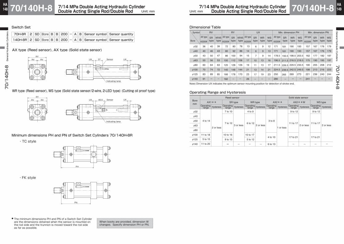
7/14 MPa Double Acting Hydraulic CylinderDouble Acting Single Rod/Double Rod 70/140H-8
70/140H-8 General Hydraulic Cylinders
Unit: mm148HA 7/14 MPa Double Acting Hydraulic Cylinder
Double Acting Single Rod/Double Rod 70/140H-8General H
ydraulic Cylinders
70/140H-8
Unit: mm 149HA
Switch Set
WR type (Reed sensor), WS type (Solid state sensor/2-wire, 2-LED type) (Cutting oil proof type)
Minimum dimensions PH and PN of Switch Set Cylinders 70/140H-8R
RV RV UX 37 Sensor
Indicating lamp
UXRY
RV RV UX 45.5 Sensor
Indicating lamp
UXRY
● The minimum dimensions PH and PN of a Switch Set Cylinder are the dimensions obtained when the sensor is mounted on the rod side and the trunnion is moved toward the rod side as far as possible.
AX type (Reed sensor), AX type (Solid state sensor)
PH
070H-8R0 2 SD Bore B B 200 - A B Sensor symbol Sensor quantity
140H-8R 2 SD Bore B B 200 - A B Sensor symbol Sensor quantity
When boots are provided, dimension W changes. Specify dimension PH or PN.
・TC style
・FK style
PN
Dimensional TableSymbol
Bore
f32
f40
f50
f63
f80
f100
f125
f140
AX type
AX205W
36
40
43
50
60
70
83
91
RV
39
43
47
53
63
72
85
-
72
80
86
100
120
140
166
182
78
86
94
106
126
144
170
-
9
9
9
13
13
14
19
-
12
13
14
16
17
21
23
-
171
171
178.5
196.5
211.5
224.5
250
280
190
190
198.5
216.5
229.5
242.5
269
-
RY UX Min. dimension PH
Note) Dimension UX indicates the optimum sensor mounting position for detection of stroke end.
Operating Range and Hysteresis
f32
f40
f50
f63
f80
f100
f125
f140
Operating range
4 to 14
11 to 18
5 to 15
11 to 20
Hysteresis Operating range Hysteresis Operating
range Hysteresis Operating range Hysteresis Operating
range Hysteresis Operating range Hysteresis
AX1**
Solid state sensorReed sensorBoremm
13
14
15
17
19
21
23
26
-
193
193
203.5
218.5
233.5
249.5
273
-
SR type
WR/WS type
AX type
AX205W
AX type
AX205W
AX type
AX205W
SR type
SR type
WR type
WS type
SR type
WR type
WS type
AX type
AX205W
SR type
WR type
WS type
WR/WS type
40
46
50
56
64
74
89
-
80
92
100
112
128
148
178
-
6
6
7
10
11
13
17
-
181
181
193.5
211.5
226.5
239.5
265
-
4 to 9
06 to 12
10 to 17
5 to 12
-
3 to 8
4 to 10
6 to 13
AX2**
- -
AX2**W
9 to 12
11 to 17
17 to 21
-
SR type WR type WS type
2 or less3 or less 2 or less
1 or less2 or less 2 or less
--
157
157
162
175
190
198
221
241
176
176
182
195
208
216
240
-
Min. dimension PN
179
179
187
197
212
223
244
-
167
167
177
190
205
213
236
-
7 to 10
07 to 12
10 to 16
9 to 15
-
9 to 12
11 to 17
17 to 21
-

7/14 MPa Double Acting Hydraulic CylinderDouble Acting Single Rod/Double Rod 70/140H-8
70/140H-8 General Hydraulic Cylinders
Unit: mm150HA 7/14 MPa Double Acting Hydraulic Cylinder
Double Acting Single Rod/Double Rod 70/140H-8General H
ydraulic Cylinders
70/140H-8
Unit: mm 151HA
Rod End Attachment
Rod eye (T-end)
Hex. screw
KK
CK
EM
ED
AV
JRAER
45°
CR
LECE
φ φ32 to 160
φ φ φ φ
φ φ180 to 250
Hex. screw
KK
CK
ED
ER
EM EF
AV
RA
45°
CR
J
LE
CE
Rod eye with spherical bearing (S-end)
80 to 12540 to 63
3°
ED
Max. HG
RA
CD
EM
CE
EN
LE
AV
EF
KK
3°
EL
Hex. screw
Grease nippleER
3°
AVCD
EFEMEN
RA
CE
LE
ED
KKMax. HG
3°
CF
EG
EL
Hex. screw
Grease nippleER
Notes)● The spherical bearings are not filled with grease. Lubricate appropriately through the grease nipple.● The bearing inner diameter and mounting width conform to JIS B8369.
AVPart number KK
Dimensional Table/Rod eye (T-end)Symbol
Bore
f32
f40
f50
f63
f80
f100
f125
f140
f150
f160
f180
f200
f224
f250
Rod B Rod B
RTH-16-H
RTH-20-H
RTH-24-H
RTH-30-H
RTH-39-H
RTH-48-H
RTH-64-H
RTH-72-H
RTH-76-H
RTH-80-H
RTH-95-H
RTH-100-H
RTH-120-H
RTH-130-H
Rod C Rod B Rod CRod C
―
RTH-16-H
RTH-20-1-H
RTH-24-1-H
RTH-30-H
RTH-39-1-H
RTH-48-1-H
RTH-56-H
RTH-60-H
RTH-64-1-H
RTH-72-1-H
RTH-80-1-H
RTH-95-1-H
RTH-100-1-H
27
32
37
47
62
77
97
112
117
122
142
152
182
197
―
27
32
37
47
62
77
82
87
97
112
122
142
152
CE
60
60
70
115
115
145
180
225
225
240
280
310
370
370
CR
20
20
25
35
35
40
50
65
65
70
80
90
100
100
J
8
8
10
15
15
20
30
30
30
40
40
50
50
50
CK
f16H10
f16H10
f20H10
f31.5H10
f31.5H10
f40H10
f50H10
f63H10
f63H10
f71H10
f80H10
f90H10
f100H10
f100H10
ER
R23
R23
R29
R39
R39
R45
R54
R74
R74
R77
R90
R99
R112
R112
EM
25
25
31.5
40
40
50
63
80
80
80
100
125
125
125
-0.1-0.4
-0.1-0.4
-0.1-0.4
-0.1-0.4
-0.1-0.4
-0.1-0.4
-0.1–0.4
-0.1-0.6
-0.1-0.6
-0.1-0.6
-0.1-0.6
-0.1-0.6
-0.1-0.6
-0.1-0.6
ED
f39
f39
f49
f62
f62
f79
f100
f130
f130
f140
160
180
200
200
M16×1.5
M20×1.5
M24×1.5
M30×1.5
M39×1.5
M48×1.5
M64×2
M72×2
M76×2
M80×2
M95×2
M100×2
M120×2
M130×2
―
M16×1.5
M20×1.5
M24×1.5
M30×1.5
M39×1.5
M48×1.5
M56×2
M60×2
M64×2
M72×2
M80×2
M95×2
M100×2
LE
23
23
28
43
43
55
65
85
85
90
100
120
130
130
RA
80
80
95
150
150
185
230
290
290
310
360
400
470
470
EF
—
—
—
—
—
—
—
—
—
—
130
140
170
180
Symbol
Bore
f40
f50
f63
f80
f100
f125
RSH-20
RSH-24
RSH-30
RSH-39
RSH-48
RSH-64
RSH-16
RSH-20-1
RSH-24-1
RSH-30-1
RSH-39-1
RSH-48-1
32
37
47
62
77
97
27
32
37
47
62
77
M20×1.5
M24×1.5
M30×1.5
M39×1.5
M48×1.5
M64×2
M16×1.5
M20×1.5
M24×1.5
M30×1.5
M39×1.5
M48×1.5
LE
25
31
38
48
58
72
RA
94.5
110.5
138
175
212
262
CD
f20
f25
f30
f40
f50
f60
0-0.012
AV KK
Dimensional Table/Rod eye with spherical bearing (S-end)
0-0.012
0-0.012
0-0.012
0-0.012
0-0.015
EN
16
20
22
28
35
44
EF
30
35
45
55
70
90
ED
55
65
80
100
120
150
ER
R27.5
R32.5
R40
R50
R60
R75
Symbol
Bore
f40
f50
f63
f80
f100
f125
Grease nipple type
JIS A type MT6×1
JIS A type MT6×1
JIS A type Rc1/8
JIS A type Rc1/8
JIS A type Rc1/8
JIS A type Rc1/8
Rod B
Dimensional Table/Grease nipple
EL
11
14
15
20
24
28
HG
11
11
15
15
15
15
Grease nipple type
JIS A type MT6×1
JIS A type MT6×1
JIS A type Rc1/8
JIS A type Rc1/8
JIS A type Rc1/8
JIS A type Rc1/8
Rod C
EL
11
14
15
20
24
28
HG
11
11
15
15
15
15
CF
―
―
―
60
50
72
CE
67
78
98
125
152
187
EM
13
17
19
23
30
38
EG
―
―
―
69
93
105
0-0.12
0-0.12
0-0.12
0-0.12
0-0.12
0-0.15
Part number
Rod B Rod BRod C Rod B Rod CRod C
CAD/DATAis available.70-140H-8/TH8 Bore K

7/14 MPa Double Acting Hydraulic CylinderDouble Acting Single Rod/Double Rod 70/140H-8
70/140H-8 General Hydraulic Cylinders
Unit: mm152HA 7/14 MPa Double Acting Hydraulic Cylinder
Double Acting Single Rod/Double Rod 70/140H-8General H
ydraulic Cylinders
70/140H-8
Unit: mm 153HA
Rod clevis (Y-end) with pin
Floating joint (F-end)Note: 70H-8 Series only
Applicable series● 70H-8● 70H-8R● 70H-8D● 70H-8RD
RetainerHex. socket head cap screw
Retainer
KK
Width acrossflatsSD
RA
ED
ER
CELE
CK
YDBL CL CM
CW
CV
CWRetainerHex. head bolt
Retainer
Hex. screwHex. screwKK
Width acrossflatsSD
RA
ED
ER
CELE
CK
YDBL CL CM
WCWC
CV
CW
KK
Hex. screw
Retainer
RetainerHex. head bolt
CR CE
J
LE
ED
RA
CK AV
45°
BL CL CM
CV
CW
5°
5°Eccentricity
Rotating anglee
e
Lock nutWidth across flats B1
Width across flats B2
h
FR
AFQ
FD FN
FK
FM
FA FC
FJ
KK
KK
100φ32 to φ80 φ φ125 to φ250
●Delivery of rod end attachment (T-end or Y-end) Hex. screw is not supplied. Tapped hole only.Rod end attachment
Rod end attachment
Drilled
Hex. screw (full dog point)
Piston rod
Piston rodLock nut
① When the lock nut and rod end attachment are additionally ordered The rod end attachment and lock nut are temporarily assembled to the piston rod for delivery. Since the lock nut is not tightened, tighten it after adjusting the position of the rod end attachment. No hex. screw is supplied.
② When only the rod end attachment is additionally ordered (without lock nut) The rod end attachment is tightened to the piston rod, and a drill hole is made on the piston rod for delivery. If the drill hole is unnecessary, give us such instructions.
Notes)● The insertion of the floating joint into the socket shall not equal or exceed the dimension of screw diameter. (Return the joint one or two turns after it gets into contact with the socket bottom, and fix it with a lock nut.) Excessive insertion can cause operation failure.
● DO NOT use together with CA, CS, CB, TA, and TC accessories.● The lock nut is indispensable in using the floating joint. Please don’t miss to order the lock nut with the floating joint.
● Make an order for the cylinder rod end lock nut at the same time.
f32
f40
f50
f63
f80
f100
f125
f140
f150
f160
f180
f200
f224
f250
RYH-16-H
RYH-20-H
RYH-24-H
RYH-30-H
RYH-39-H
RYH-48-H
RYH-64-H
RYH-72-H
RYH-76-H
RYH-80-H
RYH-95-H
RYH-100-H
RYH-120-H
RYH-130-H
―
RYH-16-H
RYH-20-1-H
RYH-24-1-H
RYH-30-H
RYH-39-1-H
RYH-48-1-H
RYH-56-H
RYH-60-H
RYH-64-1-H
RYH-72-1-H
RYH-80-1-H
RYH-95-1-H
RYH-100-1-H
―
―
―
―
―
―
97
112
117
122
142
152
182
197
―
―
―
―
―
―
77
82
87
97
112
122
142
152
BL
62
62
76.5
93
93
117
143
183
183
183
210
260
280
280
CE
60
60
70
115
115
145
180
225
225
240
280
310
370
370
CL
50
50
63.5
80
80
100
126
160
160
160
180
230
250
250
CR
―
―
―
―
―
―
50
65
65
70
80
90
100
100
CV
7
7
8
8
8
12
12
18
18
18
24
24
24
24
CW
12.5
12.5
16
20
20
25
31.5
40
40
40
40
52.5
62.5
62.5
ED
32
32
40
60
60
80
100
120
120
140
160
180
200
200
ER
R16
R16
R20
R30
R30
R40
R54
R72
R72
R77
R90
R99
R112
R112
M16×1.5
M20×1.5
M24×1.5
M30×1.5
M39×1.5
M48×1.5
M64×2
M72×2
M76×2
M80×2
M95×2
M100×2
M120×2
M130×2
―
M16×1.5
M20×1.5
M24×1.5
M30×1.5
M39×1.5
M48×1.5
M56×2
M60×2
M64×2
M72×2
M80×2
M95×2
M100×2
LE
27
27
32
50
50
60
70
90
90
100
110
130
140
140
RA
76
76
90
145
145
185
230
290
290
310
360
400
470
470
SD
32
32
41
60
60
80
―
―
―
―
―
―
―
―
YD
32
32
40
60
60
80
―
―
―
―
―
―
―
―
CK
f16
f16
f20
f31.5
f31.5
f40
f50
f63
f63
f71
f80
f90
f100
f100
H10f8
H10f8
H10f8H10f8
H10f8
H10f8
H10f8
H10f8
H10f8
H10f8
H10f8
H10f8H10f8
H10f8
CM
25
25
31.5
40
40
50
63
80
80
80
100
125
125
125
+0.4+0.1
+0.4+0.1
+0.4+0.1
+0.4+0.1
+0.4+0.1
+0.4+0.1
+0.4+0.1
+0.6+0.1
+0.6+0.1
+0.6+0.1
+0.6+0.1
+0.6+0.1
+0.6+0.1
+0.6+0.1
AV KK
f32
f40
f50
f63
Applicable bore
f40
f50
f63
f80
Part number
RFH-16
RFH-20
RFH-24
RFH-30
A
32
40
46
58
B1
22
27
32
41
B2
17
22
24
32
e
1.5
2
2.5
2.5
FA
43
53
62
78
FC
46
57
67
83
FD
13
15
18
21
FJ
89
110
129
161
FK
16
22
24
30
FM
f40
f50
f64
f76
FN
24
30
36
46
FQ
8
9
12
14
FR
28
35
41
52
h
10
12
14
17
KK
M16×1.5
M20×1.5
M24×1.5
M30×1.5
Dimensional Table/Rod clevis (Y-end) with pin
Dimensional Table/Floating joint (F-end)
J
―
―
―
―
―
―
30
30
30
40
40
50
50
50
Interference Rib
Note) When the rod clevis (Y-end) is mounted to the LC style with the pin vertically, it may interfere with the rib. In such a case, consult us.
Part numberSymbol
Bore Rod B Rod BRod C Rod B Rod CRod C
Rod B Rod C

7/14 MPa Double Acting Hydraulic CylinderDouble Acting Single Rod/Double Rod 70/140H-8
70/140H-8 General Hydraulic Cylinders
Unit: mm154HA 7/14 MPa Double Acting Hydraulic Cylinder
Double Acting Single Rod/Double Rod 70/140H-8General H
ydraulic Cylinders
70/140H-8
Unit: mm 155HA
When rod end attachment is required (rod dia. A type)
Lock Nut
Rod end attachment
Rod end attachment
KK
A
H B
C
d
Lock Nut
A
● It is recommended to change the thread diameter KK to the thread diameter of rod B (e.g. M30×1.5 → M24×1.5 in case of a 50-mm bore cylinder) and fit the rod end attachment for the rod B. In this case, specify dimensions A and KK.
The standard fitting length of the rod end attachment and piston rod is about 80% of the thread diameter. If the fitting length is insufficient due to the use of the lock nut, it is necessary to increase the thread length (dimension A) as shown below.
Dimension A
Dimensional TableSymbol
Bore
f40
f50
f63
f80
f100
f125
f140
f150
f160
KK
M24×1.5
M30×1.5
M39×1.5
M48×1.5
M64×2
M80×2
M95×2
M95×2
M100×2
KK
M20×1.5
M24×1.5
M30×1.5
M39×1.5
M48×1.5
M64×2
M72×2
M76×2
M80×2
Rod eye
RTH-20-H
RTH-24-H
RTH-30-H
RTH-39-H
RTH-48-H
RTH-64-H
RTH-72-H
RTH-76-H
RTH-80-H
Rod clevis
RYH-20-H
RYH-24-H
RYH-30-H
RYH-39-H
RYH-48-H
RYH-64-H
RYH-72-H
RYH-76-H
RYH-80-H
Floating joint
RFH-20
RFH-24
RFH-30
―
―
―
―
―
―
A
35
45
60
75
95
120
140
140
150
A
30
35
45
60
75
95
110
115
120
Dimension of rod A threaded portion Dimension of rod B threaded portion Rod end attachment for dimension of rod B threaded portion
f32
f40
f50
f63
f80
f100
f125
f140
f150
f160
f180
f200
f224
f250
Part number
LNH-16F-H
LNH-20F-H
LNH-24F-H
LNH-30F-H
LNH-39F-H
LNH-48F-H
LNH-64F-H
LNH-72F-H
LNH-76F-H
LNH-80F-H
LNH-95F-H
LNH-100F-H
LNH-120F-H
LNH-130F-H
Rod B
B
22
27
32
41
55
70
90
100
105
110
130
135
165
180
C
25.4
31.2
37.0
47.3
63.5
80.8
104
115
121
127
150
156
191
208
H
10
12
14
17
20
26
35
38
40
43
47
50
60
65
Part number
―
LNH-16F-H
LNH-20F-H
LNH-24F-H
LNH-30F-H
LNH-39F-H
LNH-48F-H
LNH-56F-H
LNH-60F-H
LNH-64F-H
LNH-72F-H
LNH-80F-H
LNH-95F-H
LNH-100F-H
Rod C
B
―
22
27
32
41
55
70
80
85
90
100
110
130
135
C
―
25.4
31.2
37.0
47.3
63.5
80.8
92.4
98.1
104
115
127
150
156
H
―
10
12
14
17
20
26
30
33
35
38
43
47
50
Part number
―
LNH-24F-H
LNH-30F-H
LNH-39F-H
LNH-48F-H
LNH-64F-H
LNH-80F-H
LNH-95F-H
LNH-95F-H
LNH-100F-H
―
―
―
―
Rod A
d
―
M24×1.5
M30×1.5
M39×1.5
M48×1.5
M64×2
M80×2
M95×2
M95×2
M100×2
―
―
―
―
H
―
14
17
20
26
35
43
47
47
50
―
―
―
―
f32
f40
f50
f63
f80
f100
f125
f140
f150
f160
f180
f200
f224
f250
Rod B
40
45
50
60
80
95
125
140
150
155
180
190
230
250
Rod C
― 40
45
50
60
80
95
105
120
125
140
155
180
190
Rod A
― 50
60
80
95
125
155
180
180
190
――――
B
―
32
41
55
70
90
110
130
130
135
―
―
―
―
C
―
37.0
47.3
63.5
80.8
104
127
150
150
156
―
―
―
―
d
―
M16×1.5
M20×1.5
M24×1.5
M30×1.5
M39×1.5
M48×1.5
M56×2
M60×2
M64×2
M72×2
M80×2
M95×2
M100×2
d
M16×1.5
M20×1.5
M24×1.5
M30×1.5
M39×1.5
M48×1.5
M64×2
M72×2
M76×2
M80×2
M95×2
M100×2
M120×2
M130×2
Dimensional Table/Lock nutSymbol
Bore
Symbol
Bore
CAD/DATAis available.70-140H-8/TH8 Bore K

7/14 MPa Double Acting Hydraulic CylinderDouble Acting Single Rod/Double Rod 70/140H-8
70/140H-8 General Hydraulic Cylinders
Unit: mm156HA 7/14 MPa Double Acting Hydraulic Cylinder
Double Acting Single Rod/Double Rod 70/140H-8General H
ydraulic Cylinders
70/140H-8
Unit: mm 157HA
Parallel Pin
Retainer
C D E
BL
CK
2-L
F
G
H
IJ
K
Dimensional Table/Parallel pinSymbol
Bore
f32
f40
f50
f63
f80
f100
f125
f140
f150
f160
BL
62
62
76.5
93
93
117
143
183
183
183
C
4
4
5
5
5
7
7
10
10
10
CK
f16
f16
f20
f31.5
f31.5
f40
f50
f63
f63
f71
D
3
3
3
3
3
5
5
8
8
8
E
3
3
3
4.75
4.75
5
5
8
8
8
Dimensional Table/Retainer
f32
f40
f50
f63
f80
f100
f125
f140
f150
f160
F
25
25
32
32
32
50
65
75
75
75
G
14
14
18
18
18
30
40
48
48
48
H
7
7
7.5
7.5
7.5
10
12
17
17
17
I
7
7
7.5
7.5
7.5
10
10
13
13
13
J
14
14
15
15
15
20
22
30
30
30
K
3
3
4.5
4.5
4.5
6
6
9
9
9
L
f6.5
f6.5
f7
f7
f7
f10
f12
f14
f14
f14
M6
M6
M6
M6
M6
M8
M10
M12
M12
M12
● The tolerance of CK is f8.
Retainer mounting bolt size
Symbol
Bore

7/14 MPa Double Acting Hydraulic CylinderDouble Acting Single Rod/Double Rod 70/140H-8
70/140H-8 General Hydraulic Cylinders
158HA 7/14 MPa Double Acting Hydraulic Cylinder
Double Acting Single Rod/Double Rod 70/140H-8General H
ydraulic Cylinders
70/140H-8
159HA
The cylinder will be delivered with the rod end attachment temporarily mounted on the rod.After making the final adjustment, firmly tighten the rod end attachment, fit the copper piece into the set screw hole, and tighten the set screw.Adhesive has been applied to the set screw for prevention of loosening. However, the effect of the adhesive varies depending on the conditions of use, etc.Confirm the effect by yourself.
The semi-standard ordering systemThe following contents can be easily specified using the semi-standard symbols and specification symbols (position/dimension/material symbols).
How to order Series Model number - × Semi-standard symbol Position/Dimension/Material symbols
① ② ③ ④
Chrome plating
BB
Rod: Stainless steel
Order contentsPosition
②Symbol Description ③Symbol Description ④Symbol Description
Rod side
Cap side
Both sides
Dimension Material①Semi-standard symbol
STD
Example
TD-RS
TD-HS
TD-BS
BB-
BG-0.02Plating thickness 0.02 mm
is a desired dimension BB of up to 70 mm.
To specify SD style with dimension BB of 50 mm on both sides
70H-8R 2SD80BB100-ABAH2-X STD TD-BS, BB-50
70H-8 2LB80BB100-AB-X STB BG-0.02
70H-8R 2LB80BB100-ABAH2-X SPR PR-10
Example To plate the tube inner surface 0.02 mm in thickness
Example
Example
To specify piston rod made of SUS304 with plating thickness of 0.02 mm
70H-8R 2CB80BB100-ABAH2-T-X MDC
STB
■Tie rods extension
■Hard chrome plated on the inside of cylinder tube (standard type only)
Note) Consult us for any special thickness of chrome plating other than 0.02 mm.
PR-10Material:SUS304 Plating thickness
0.02mm
No need to specify the material/dimension/position symbol.
SPR■Stainless steel piston rod (φ40 to φ100)
Note) Consult us for any special requirement other than material SUS304 or 0.02 mm thickness of chrome plating.
MDC■Rod end attachments (T, Y, S) with a set screw and a copper piece (φ32 to φ160)
CAUTION
Example 1) When it is required to deliver the cylinder with a set screw and a copper piece attached to the Y-end (to be finally tightened by the customer) without a drill hole.
(Reference) Standard cylinders (without specifying the symbol ‘MDC’) will be delivered in the following state.
Rod end attachment
Threaded hole for set screw
+
Set screw and copper piece
Set (bag)(Example)
Copper piece Set screw
After rod end attachment is tightened
Set screw (full dog point)
Drilling (to make a drilled hole in the piston rod)
Notes)1) Tolerance of dimension BB is about 2 mm due to elongation by tightening. When precise dimension BB is required, specify the value.
2) For the LB or LC style, only upper two tie rods (on the side opposite to the accessory side) can be extended. For flange or clevis type, four tie rods on the side without the accessory can be extended.
★
Port
Cushion valves
A
B
C
D
PH
PN
PPC
Example
Example
Example
Example
To change the port and cushion valve positions from the cap side to the rod side (AB on rod side, BC on cap side)70H-8 2LA80BB100-AB-X PPC PC-BC
■Change of port and cushion valve positions on the cap side
■Intermediate flange location change (dimension PN)
■Water-glycol working fluid
PC-
FKPN-
FWF
70H-8 6LB80BB100-AB-X FWF WF-WG
WF-WG
WF-WG:Water-glycol fluid
MFK
To change dimension PH to 1100 mm140H-8 2FK80BB1800-AB-X MFK FKPN-1100
■Intermediate trunnion location change (dimension PH)
TCPH-MTC
To change dimension PH to 360 mm70H-8R 2TC63BB500-AB-X MTC TCPH-360
is a new dimension.
is a new dimension.
Order contents ①
Notes) 1) Iron tubing (standard type) is plated with hard chrome and tested with water-glycol fluid.
2) Stainless steel tubing (Switch Set) is not plated in conformity with the standard and tested with water-glycol fluid.
Position
②Symbol Description ②Symbol Description ②Symbol Description
Dimension MaterialSemi-standard symbol
indicates the port and cushion valve positions on the cap side.

7/14 MPa Double Acting Hydraulic CylinderDouble Acting Single Rod/Double Rod 70/140H-8
70/140H-8 General Hydraulic Cylinders
Unit: mm160HA 7/14 MPa Double Acting Hydraulic Cylinder
Double Acting Single Rod/Double Rod 70/140H-8General H
ydraulic Cylinders
70/140H-8
161HA
The thread type can be specified by the cylinder model number without using the semi-standard symbol and specification symbols.Example) 70H-8 2LA50BB100- GAB -TL
G:Port G thread type N:NPT thread typePort positionCushion valve position
Bush Specify this size.
For the G thread port size, refer to the dimensional table in the model specification field.
Note) Select a standard port size and a reduced port size.
Inapplicable to: ● All types of rod A● Rod B or C with LA style
Inapplicable to: ● All types of rod A● Rod B or C with LA style
Specify the port size.
Specify the port size.
★Specify the size to reduce the port size without using a bushing.
Order contents
PBS
To reduce the port size to Rc1/2 by mounting a bushing to 140H-8 CA style 80-mm bore cylinder (standard port size Rc3/4)140H-8 2CA80BB300-AB-X PBS RC-4.00
■Additional port of bushing
Notes 1) Select a reduced port size after mounting a bushing.
2) For reduction by more than two steps by using a bushing, consult us.
■G thread type/NPT thread type (φ32 toφ160) (only standard port size)
RC-1.00 RC-2.00 RC-3.00 RC-4.00 RC-6.00 RC-8.00 RC-10.00 RC-12.00
Rc1/8 Rc1/4 Rc3/8 Rc1/2 Rc3/4 Rc1
Rc1 1/4 Rc1 1/2
Specify the size only Port size selectable for cylinder bore (◎: Standard port size)
PRT
To reduce the cover port directly to Rc3/8 without mounting a bushing to 63-mm bore cylinder (standard port size Rc1/2)
70H-8R 2CA80BB100-ABAH2-X PRT RC-3.00
■Reduction of Rc thread port size (φ32 to φ160)
Note) Increasing the port diameter changes the dimensions. Consult us.
Note) Increasing the port diameter changes the dimensions. Consult us.
RC-1.00 RC-2.00 RC-3.00 RC-4.00 RC-6.00 RC-8.00 RC-10.00
Rc1/8 Rc1/4 Rc3/8 Rc1/2 Rc3/4 Rc1
Rc1 1/4
32○ ○ ◎ × × × ×
○ ○ ◎ × × × ×
× ○ ○ ◎ × × ×
× ○ ○ ◎ × × ×
× × ○ ○ ◎ × ×
× × ○ ○ ◎ × ×
× × × ○ ○ ◎ ×
× × × ○ ○ ◎ ×
× × × ○ ○ ◎ ×
× × × ○ ○ ◎ ×
40 50 63 80 100 125 140 150 160
Port size selectable for cylinder bore (◎: Standard port size)
PTN
Cap side
To reduce the port size for a cylinder bore of 50 mm (standard size 1/2) to NPT 3/870H-8 2CB50BB100-NAB-X PTN N-3.00
■Reduction of NPT thread port size (φ32 to φ160)
N-1.00 N-2.00 N-3.00 N-4.00 N-6.00 N-8.00 N-10.00
NPT1/8 NPT1/4 NPT3/8 NPT1/2 NPT3/4 NPT1
NPT1 1/4
32○ ○ ◎ × × × ×
○ ○ ◎ × × × ×
× ○ ○ ◎ × × ×
× ○ ○ ◎ × × ×
× × ○ ○ ◎ × ×
× × ○ ○ ◎ × ×
× × × ○ ○ ◎ ×
× × × ○ ○ ◎ ×
× × × ○ ○ ◎ ×
× × × ○ ○ ◎ ×
40 50 63 80 100 125 140 150 160
To order the standard port size (◎), see the following.
Position
②Symbol Description
③Symbol Description
Specify the size only
③Symbol Description
③Symbol Description ④Symbol Description
Dimension Material①Semi-standard symbol
①Semi-standard symbol
①Semi-standard symbol
Example
Note
Note
How to order Series Model number - × Semi-standard symbol Position/Dimension/Material symbols
① ② ③ ④
Special wear rings
Backup ring
Bush
VD
Metal sliding
Order contentsPosition Dimension Material
MBH
Example
■Reinforced bearing type (for resistance to lateral load)
■Outline drawing
Add ‘MBH’ to the end of the symbol for ordering (specification symbols are unnecessary).
140H-8R 2CB140BB1200-ABAH2 MBH
(Reference) The standard gland has metal sliding surfaces as shown below.
Rods A and B have the same dimensions as the standard type.For rod C, see the following dimensional table.
Dimensional TableRod type
Dimension symbol
Mounting style
Bore
Rod CVD
SD・LA・LB・LC・FA・FB・FC・FD・FK・FZ・CA・CB・CS・TA・TC FY
10 9 10 9 10 10 10 10 10
MBH10 6 10 8 8 9 10 10 9
MBHf40 f50 f63 f80
f100 f125 f140 f150 f160
①Semi-standard symbol ②Symbol Description ③Symbol Description ④Symbol Description
Type for improving the load resistance of the bearing block by using abrasion-resistant special wear rings for high load in the gland bush sliding part.Since the dimensions and appearance are the same as those of the standard type, the cylinder can be mounted in the same manner.

7/14 MPa Double Acting Hydraulic CylinderDouble Acting Single Rod/Double Rod 70/140H-8
70/140H-8 General Hydraulic Cylinders
Unit: mm162HA 7/14 MPa Double Acting Hydraulic Cylinder
Double Acting Single Rod/Double Rod 70/140H-8General H
ydraulic Cylinders
70/140H-8
Unit: mm 163HA
A00 A51
Rod C Special Rod End Shapes
Table of Basic Dimensions (Standard dimensions)
Width across flats *S
KM×KP
*φMM
*R
3
A W
15°
*φMM
15°3
W
Table of Basic Dimensions
Bore
f40
f50
f63
f80
f100
f125
f140
f150
f160
f180
f200
f224
f250
*MM
f18
f22.4
f28
f35.5
f45
f56
f63
f67
f71
f80
f90
f100
f112
W
30
30
35
35
40
45
50
50
55
55
55
60
65
*R
1
1
1
1.6
1.6
1.6
2
2
2
2
2
2
2
*MM
f18
f22.4
f28
f35.5
f45
f56
f63
f67
f71
f80
f90
f100
f112
KM
M16
M20
M24
M30
M39
M48
M56
M60
M64
M72
M80
M95
M100
KP
1.5
1.5
1.5
1.5
1.5
1.5
2
2
2
2
2
2
2
A
25
30
35
45
60
75
80
85
95
110
120
140
150
W
30
30
35
35
40
45
50
50
55
55
55
60
65
*S
14
19
24
30
41
50
55
60
65
75
85
Bore
f40
f50
f63
f80
f100
f125
f140
f150
f160
f180
f200
f224
f250
Change of Rod End Shape■You can specify the shape and dimension of the rod end as shown below using the semi-standard symbols and dimension symbols. (No need to specify the dimension symbol if you order a cylinder with the basic dimension. Specify only the semi-standard symbol.)
How to order Series Model number- × Semi-standard symbol Dimension symbol (Specify only when the dimension differs from the basic dimension.)
Example 1)A53
KM and KP need to be specified as a pair.
●
1.75 or less2 2.5 or more
KP (pitch)4 5
KP (pitch)×2
Dimension A1
Example 2)A54 ●
Note) In case of A54, if KM and KP are changed, dimension A1 is changed as shown below.
*φMM
*R
No. of chamfered surfaces DN
No. of chamfered surfaces DN
Width across flats *S
KM×KP 3
L
W
15°
A
*φMM
Width across flats *S
KM×KP
L*A1
A W
The *-marked dimensions are fixed.If it is necessary to change the fixed dimensions, consult us.
Bore: 63 mm, rod C, rod end shape: A53, A=50, W=50, screw: M22×1.5, 2 surfaces chamfered, position of width across flats L=1070H-8 2FA63CB200-AB-X A53A-50, KM-22, KP-1.5, L-10, W-50
Bore: 63 mm, rod C, rod end shape: A54, with basic dimensions
●●
Drill hole
A53
Use this shape to move the width across flats S of ‘A00’.
15°KM×KP
L
No. of chamfered surfaces DN
*R
3
A W
*φMM
Table of Basic Dimensions
KM
M16
M20
M24
M30
M39
M48
M56
M60
M64
KP
1.5
1.5
1.5
1.5
1.5
1.5
2
2
2
A
25
30
35
45
60
75
80
85
95
W
30
30
35
35
40
45
50
50
55
*S
14
19
24
30
41
50
55
60
65
DN
2
2
2
2
2
2
2
2
2
*R
1
1
1
1.6
1.6
1.6
2
2
2
L
0
0
0
0
0
0
0
0
0
*MM
f18
f22.4
f28
f35.5
f45
f56
f63
f67
f71
Bore
f40
f50
f63
f80
f100
f125
f140
f150
f160
A54KM×KP
*A1
*φMM
A W
L
Table of Basic Dimensions
*MM
f18
f22.4
f28
f35.5
f45
f56
f63
f67
f71
f80
f90
f100
f112
KM
M16
M20
M24
M30
M39
M48
M56
M60
M64
M72
M80
M95
M100
KP
1.5
1.5
1.5
1.5
1.5
1.5
2
2
2
2
2
2
2
A
25
30
35
45
60
75
80
85
95
110
120
140
150
*A1
4
4
4
4
4
4
5
5
5
5
5
5
5
W
30
30
35
35
40
45
50
50
55
55
55
60
65
Bore
f40
f50
f63
f80
f100
f125
f140
f150
f160
f180
f200
f224
f250
L
0
0
0
0
0
0
0
0
0
0
0
DN
2
2
2
2
2
2
2
2
2
2
2
*S
14
19
24
30
41
50
55
60
65
75
85
Drill hole
Drill hole
Drill hole
Rod C
A81
This shape applies only to 7 MPa type.For the 14 MPa type, consult us.
Note) The number of chamfered surfaces DN is 2 (standard) or 4 only.
15°
KM×KP
*φMM
L
A
3
W
Table of Basic Dimensions
KP
1.75
2
2.5
3
3.5
4
2
2
2
A
15
20
24
33
36
45
54
54
58
*S
14
19
24
30
41
50
55
60
65
L
0
0
0
0
0
0
0
0
0
DN
2
2
2
2
2
2
2
2
2
W
30
30
35
35
40
45
50
50
55
KM
M12
M16
M20
M27
M30
M39
M45
M45
M48
*MM
f18
f22.4
f28
f35.5
f45
f56
f63
f67
f71
Bore
f40
f50
f63
f80
f100
f125
f140
f150
f160
● The *-marked dimensions are fixed.If it is necessary to change the fixed dimensions, consult us.●
Width across flats *S
No. of chamfered surfaces DN
Width across flats *S
No. of chamfered surfaces DN
Width across flats *S
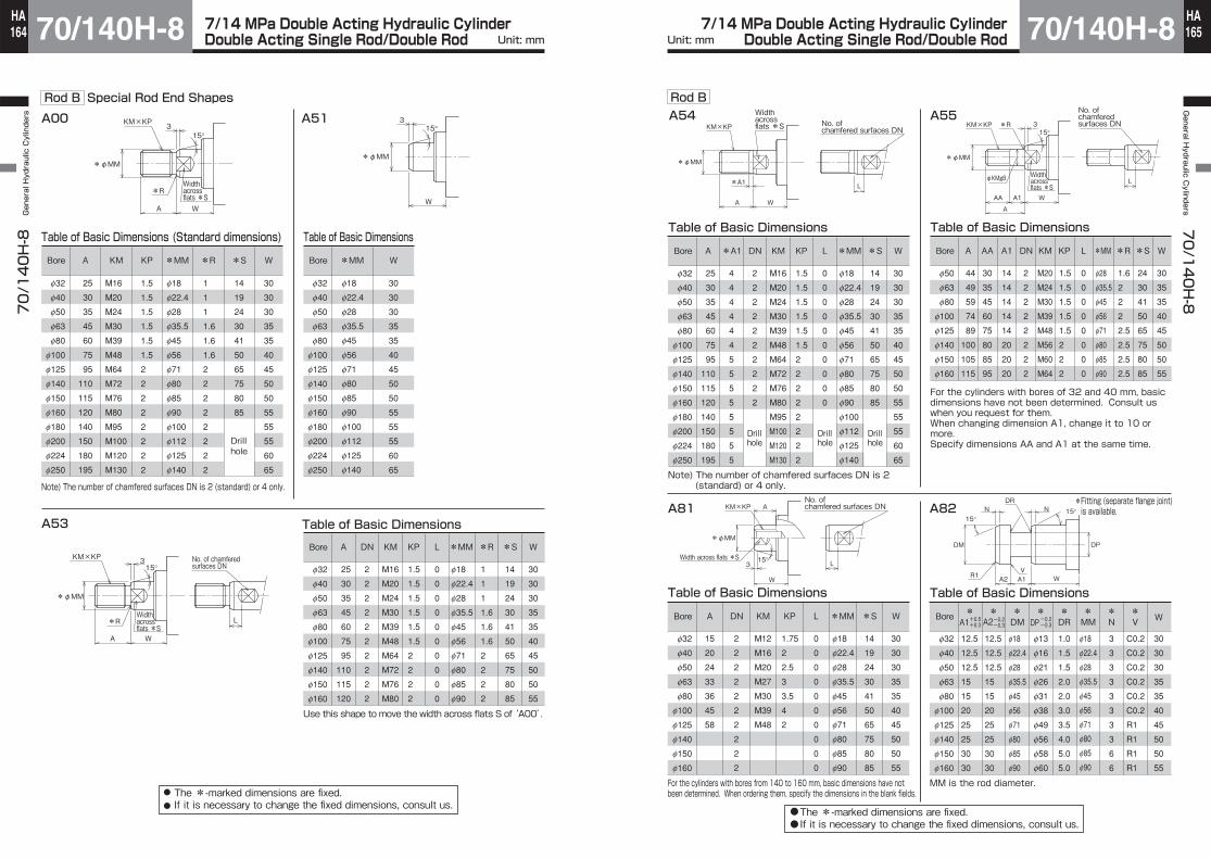
7/14 MPa Double Acting Hydraulic CylinderDouble Acting Single Rod/Double Rod 70/140H-8
70/140H-8 General Hydraulic Cylinders
Unit: mm164HA 7/14 MPa Double Acting Hydraulic Cylinder
Double Acting Single Rod/Double Rod 70/140H-8General H
ydraulic Cylinders
70/140H-8
Unit: mm 165HA
Rod B Special Rod End Shapes
KM×KP
*φMM
*R
3
A W
15°
*φMM
15°3
W
Table of Basic Dimensions (Standard dimensions)
Note) The number of chamfered surfaces DN is 2 (standard) or 4 only.
A51
A
25
30
35
45
60
75
95
110
115
120
140
150
180
195
KM
M16
M20
M24
M30
M39
M48
M64
M72
M76
M80
M95
M100
M120
M130
KP
1.5
1.5
1.5
1.5
1.5
1.5
2
2
2
2
2
2
2
2
*MM
f18
f22.4
f28
f35.5
f45
f56
f71
f80
f85
f90
f100
f112
f125
f140
W
30
30
30
35
35
40
45
50
50
55
55
55
60
65
*S
14
19
24
30
41
50
65
75
80
85
Drill hole
*R
1
1
1
1.6
1.6
1.6
2
2
2
2
2
2
2
2
Bore
f32
f40
f50
f63
f80
f100
f125
f140
f150
f160
f180
f200
f224
f250
Table of Basic Dimensions
Table of Basic Dimensions
Bore
f32
f40
f50
f63
f80
f100
f125
f140
f150
f160
f180
f200
f224
f250
*MM
f18
f22.4
f28
f35.5
f45
f56
f71
f80
f85
f90
f100
f112
f125
f140
W
30
30
30
35
35
40
45
50
50
55
55
55
60
65
15°KM×KP
L*R
3
A W
*φMM
35A
*MM
f18
f22.4
f28
f35.5
f45
f56
f71
f80
f85
f90
Use this shape to move the width across flats S of ‘A00’.
KM
M16
M20
M24
M30
M39
M48
M64
M72
M76
M80
KP
1.5
1.5
1.5
1.5
1.5
1.5
2
2
2
2
A
25
30
35
45
60
75
95
110
115
120
W
30
30
30
35
35
40
45
50
50
55
*S
14
19
24
30
41
50
65
75
80
85
L
0
0
0
0
0
0
0
0
0
0
DN
2
2
2
2
2
2
2
2
2
2
*R
1
1
1
1.6
1.6
1.6
2
2
2
2
Bore
f32
f40
f50
f63
f80
f100
f125
f140
f150
f160
A00
The *-marked dimensions are fixed.If it is necessary to change the fixed dimensions, consult us.
Width across flats *S
No. of chamfered surfaces DN
Width across flats *S
●
●
A54KM×KP
*A1
*φMM
A W
L
15°KM×KP
*φMM
φKMg8
*R 3
AA A1 W
A
L
A55
Table of Basic Dimensions
*MM
f28
f35.5
f45
f56
f71
f80
f85
f90
KM
M20
M24
M30
M39
M48
M56
M60
M64
KP
1.5
1.5
1.5
1.5
1.5
2
2
2
A
44
49
59
74
89
100
105
115
W
30
35
35
40
45
50
50
55
*S
24
30
41
50
65
75
80
85
L
0
0
0
0
0
0
0
0
DN
2
2
2
2
2
2
2
2
*R
1.6
2
2
2
2.5
2.5
2.5
2.5
A1
14
14
14
14
14
20
20
20
AA
30
35
45
60
75
80
85
95
Bore
f50
f63
f80
f100
f125
f140
f150
f160
A82
DM DP
VA1A2
N N 15°15°
DR
R1 W
Rod B
Table of Basic Dimensions
12.5
12.5
12.5
15
15
20
25
25
30
30
Bore
f32
f40
f50
f63
f80
f100
f125
f140
f150
f160
12.5
12.5
12.5
15
15
20
25
25
30
30
DM
f18
f22.4
f28
f35.5
f45
f56
f71
f80
f85
f90
f13
f16
f21
f26
f31
f38
f49
f56
f58
f60
DR
1.0
1.5
1.5
2.0
2.0
3.0
3.5
4.0
5.0
5.0
MM
f18
f22.4
f28
f35.5
f45
f56
f71
f80
f85
f90
N
3
3
3
3
3
3
3
3
6
6
V
C0.2
C0.2
C0.2
C0.2
C0.2
C0.2
R1
R1
R1
R1
W
30
30
30
35
35
40
45
50
50
55
+0.5+0.3
-0.2-0.3
-0.2-0.3A1 A2 DP
MM is the rod diameter.For the cylinders with bores from 140 to 160 mm, basic dimensions have not been determined. When ordering them, specify the dimensions in the blank fields.
A81
15°
KM×KP
*φMM
L
A
3
W
Table of Basic Dimensions
Drill hole
Drill hole
Drill hole
Note) The number of chamfered surfaces DN is 2 (standard) or 4 only.
Bore
f32
f40
f50
f63
f80
f100
f125
f140
f150
f160
f180
f200
f224
f250
*MM
f18
f22.4
f28
f35.5
f45
f56
f71
f80
f85
f90
f100
f112
f125
f140
KM
M16
M20
M24
M30
M39
M48
M64
M72
M76
M80
M95
M100
M120
M130
KP
1.5
1.5
1.5
1.5
1.5
1.5
2
2
2
2
2
2
2
2
A
25
30
35
45
60
75
95
110
115
120
140
150
180
195
*A1
4
4
4
4
4
4
5
5
5
5
5
5
5
5
*S
14
19
24
30
41
50
65
75
80
85
L
0
0
0
0
0
0
0
0
0
0
DN
2
2
2
2
2
2
2
2
2
2
W
30
30
30
35
35
40
45
50
50
55
55
55
60
65
Table of Basic Dimensions
A
15
20
24
33
36
45
58
DN
2
2
2
2
2
2
2
2
2
2
KM
M12
M16
M20
M27
M30
M39
M48
KP
1.75
2
2.5
3
3.5
4
2
L
0
0
0
0
0
0
0
0
0
0
*MM
f18
f22.4
f28
f35.5
f45
f56
f71
f80
f85
f90
*S
14
19
24
30
41
50
65
75
80
85
W
30
30
30
35
35
40
45
50
50
55
Bore
f32
f40
f50
f63
f80
f100
f125
f140
f150
f160
The *-marked dimensions are fixed.If it is necessary to change the fixed dimensions, consult us.
*Fitting (separate flange joint) is available.
* * * * * * * *
Width across flats *S
Width across flats *S
No. of chamfered surfaces DN
Width across flats *S
No. of chamfered surfaces DN
●●
For the cylinders with bores of 32 and 40 mm, basic dimensions have not been determined. Consult us when you request for them.When changing dimension A1, change it to 10 or more.Specify dimensions AA and A1 at the same time.
No. of chamfered surfaces DN

7/14 MPa Double Acting Hydraulic CylinderDouble Acting Single Rod/Double Rod 70/140H-8
70/140H-8 General Hydraulic Cylinders
Unit: mm166HA 7/14 MPa Double Acting Hydraulic Cylinder
Double Acting Single Rod/Double Rod 70/140H-8General H
ydraulic Cylinders
70/140H-8
Unit: mm 167HA
A00 A51
Table of Basic Dimensions (Standard dimensions)
KM×KP
*φMM
*R
3
A W
15°
*φMM
15°3
W
*R
1
1.6
1.6
1.6
2
2
2
2
2
*MM
f28
f35.5
f45
f56
f71
f90
f100
f100
f112
KM
M24
M30
M39
M48
M64
M80
M95
M95
M100
KP
1.5
1.5
1.5
1.5
2
2
2
2
2
A
35
45
60
75
95
120
140
140
150
W
35
41
48
51
57
57
57
57
57
*S
24
30
41
50
65
85
Bore
f40
f50
f63
f80
f100
f125
f140
f150
f160
Table of Basic Dimensions
Bore
f40
f50
f63
f80
f100
f125
f140
f150
f160
*MM
f28
f35.5
f45
f56
f71
f90
f100
f100
f112
W
35
41
48
51
57
57
57
57
57
Rod A Special Rod End Shapes
A53
15°KM×KP
L*R
3
A W
*φMM
Use this shape to move the width across flats S of‘A00’.
Table of Basic Dimensions
KM
M24
M30
M39
M48
M64
M80
KP
1.5
1.5
1.5
1.5
2
2
A
35
45
60
75
95
120
W
35
41
48
51
57
57
*S
24
30
41
50
65
85
DN
2
2
2
2
2
2
*R
1
1.6
1.6
1.6
2
2
L
0
0
0
0
0
0
*MM
f28
f35.5
f45
f56
f71
f90
Bore
f40
f50
f63
f80
f100
f125
A54
KM×KP
*A1
*φMM
A W
L
Table of Basic Dimensions
Bore
f40
f50
f63
f80
f100
f125
f140
f150
f160
*MM
f28
f35.5
f45
f56
f71
f90
f100
f100
f112
KM
M24
M30
M39
M48
M64
M80
M95
M95
M100
KP
1.5
1.5
1.5
1.5
2
2
2
2
2
A
35
45
60
75
95
120
140
140
150
*A1
4
4
4
4
5
5
5
5
5
*S
24
30
41
50
65
85
L
0
0
0
0
0
0
↑↑
DN
2
2
2
2
2
2
Drill hole Drill hole Drill hole
Drill hole
Drill hole
↑↑
W
35
41
48
51
57
57
57
57
57
The *-marked dimensions are fixed.If it is necessary to change the fixed dimensions, consult us.
Width across flats *S
Width across flats *S
Width across flats *SNo. of
chamfered surfaces DN
No. of chamfered surfaces DN
●●
Drill hole
Drill holeDrill hole
Table of Basic Dimensions
12.5
15
15
20
25
30
Bore
f40
f50
f63
f80
f100
f125
12.5
15
15
20
25
30
f28
f35.5
f45
f56
f71
f90
f21
f26
f31
f38
f49
f60
1.5
2.0
2.0
3.0
3.5
5.0
f28
f35.5
f45
f56
f71
f90
3
3
3
3
3
6
C0.2
C0.2
C0.2
C0.2
R1
R1
35
41
48
51
57
57
+0.5+0.3
-0.2-0.3
-0.2-0.3
*DM *DP *MM
*V*A1*A2
*N *N 15°15°
*DR
*R1 W
A1 A2 DP
MM is the rod diameter.
DM*DR
*MM
*N
*V W
* * * *
Rod AA81
15°
KM×KP
*φMM
L
A
3
W
Note) ●The number of chamfered surfaces DN is 2 (standard) or 4 only.
Table of Basic Dimensions
KP
2.5
3
3.5
4
2
A
24
33
36
45
58
*S
24
30
41
50
65
L
0
0
0
0
0
DN
2
2
2
2
2
W
35
41
48
51
57
KM
M20
M27
M30
M39
M48
*MM
f28
f35.5
f45
f56
f71
Bore
f40
f50
f63
f80
f100
A55
When changing dimension A1, change it to 10 or more.Specify dimensions AA and A1 at the same time.
15°KM×KP
*φMM
φKMg8
*R 3
AA A1 W
A
L
Table of Basic Dimensions
*MM
f28
f35.5
f45
f56
f71
f90
KM
M20
M24
M30
M39
M48
M64
KP
1.5
1.5
1.5
1.5
1.5
2
A
44
49
59
74
89
115
W
35
41
48
51
57
57
*S
24
30
41
50
65
85
L
0
0
0
0
0
0
DN
2
2
2
2
2
2
*R
1.6
2
2
2
2.5
2.5
A1
14
14
14
14
14
20
AA
30
35
45
60
75
95
Bore
f40
f50
f63
f80
f100
f125
A82
The *-marked dimensions are fixed.If it is necessary to change the fixed dimensions, consult us.
*Fitting (separate flange joint) is available.
Width across flats *S
Width across flats *S
No. of chamfered surfaces DN
No. of chamfered surfaces DN
●●

7/14 MPa Double Acting Hydraulic CylinderDouble Acting Single Rod/Double Rod 70/140H-8
70/140H-8 General Hydraulic Cylinders
Unit: mm168HA 7/14 MPa Double Acting Hydraulic Cylinder
Double Acting Single Rod/Double Rod 70/140H-8General H
ydraulic Cylinders
70/140H-8
Unit: mm 169HA
Separate Flange Joint (M-end): Only for piston rod end shape A82
Reverse faceSpot facing dia. D4 depth H
4-D345°
B B
3
J
C C
D2D1A
F
G
E
Additional order for this item is needed. Specify as RMH-**.●
Dimensional Table/Rod BSymbol
Bore
f32
f40
f50
f63
f80
f100
f125
f140
f150
f160
RMH-18
RMH-22
RMH-28
RMH-36
RMH-45
RMH-56
RMH-70
RMH-80
RMH-85
RMH-90
f49
f57
f71
f77
f100
f124
f150
f174
f180
f193
Part number
23
27
34
37
48.5
60.5
73.5
85.5
88.5
95
B C D1 D2 D3 D4 E F G H J XA
1
1.5
1.5
2
2
3
3.5
4
5
5
f19
f23
f29
f38
f48
f60
f74
f84
f90
f95
f13.5
f16.5
f21.5
f27
f33
f41
f53
f60
f62
f64
f6.6
f9
f11
f11
f14
f18
f22
f26
f26
f30
f11
f14
f17.5
f17.5
f20
f26
f32
f39
f39
f43
18.5
16.4
14.2
19.2
17
22.5
28.5
24.5
34.5
31
25
25
25
30
30
40
50
50
60
60
12.5
12.5
12.5
15
15
20
25
25
30
30
6.5
8.6
10.8
10.8
13
17.5
21.5
25.5
25.5
29
f34
f40
f50
f55
f76
f92
f112
f129
f135
f144
–
–
–
–
16
7
14
40
26
9
Dimensional Table/Rod A
f40
f50
f63
f80
f100
f125
RMH-28
RMH-36
RMH-45
RMH-56
RMH-70
RMH-90
f71
f77
f100
f124
f150
f193
34
37
48.5
60.5
73.5
95
1.5
2
2
3
3.5
5
f29
f38
f48
f60
f74
f95
f21.5
f27
f33
f41
f53
f64
f11
f11
f14
f18
f22
f30
f17.5
f17.5
f20
f26
f32
f43
14.2
19.2
17
22.5
28.5
31
25
30
30
40
50
60
12.5
15
15
20
25
30
10.8
10.8
13
17.5
21.5
29
f50
f55
f76
f92
f112
f144
15
–
17
24
26
43
Note) In the case of LC mounting and rod B, add dimension X as the lower limit to dimension W of the cylinder body.
Note) In the case of LB mounting and rod A, add dimension Y as the lower limit to dimension W of the cylinder body.
Symbol
BorePart number B C D1 D2 D3 D4 E F G H J XA

7/14 MPa Double Acting Hydraulic Cylinder70/140H-870/140H-8 General Hydraulic Cylinders
170HA
7/14 MPa Double Acting Hydraulic Cylinder 70/140H-8General H
ydraulic Cylinders
70/140H-8
171HA
❶
❷
❸
❹❺
❻
❼
❽
Setting method of sensor detection position
WR type/WS type
Notes on assembly
Tightening of tie rods
Adjust until the sensor comes in contact with the cylinder tube.
Hold with hands.
Hold with hands.
Tie rod size (M6 to M10): Hex. screw M5 [tightening torque: 1 to 2 N・m]Tie rod size (M12 to M27): Hex. screw M6 [tightening torque: 2 to 3 N・m]
Tie rod
Sensor mounting screw M4 [tightening torque: 0.6 to 1 N・m]
AX type
Tie rod
Adjust until the sensor comes in contact with the cylinder tube.
Hex. screw M5 [tightening torque: 1 to 2 N・m]
Sensor mounting screw M4 [tightening torque: 0.6 to 1.0 N・m]
Specified Tie Rod Tightening Torque Table
Bore (mm)
Bore (mm)
Tie rod screw
Tightening torque (N・m)
Tie rod screw
Tightening torque (N・m)
70H-8
140H-8
70H-8
140H-8
f32
M10×1.25
20
f140
M24×1.5
310
610
f150
M27×1.5
450
880
f160
M27×1.5
450
880
f180
M30×1.5
630
1100
f200
M33×1.5
830
1400
f224
M39×1.5
1400
2400
f250
M42×1.5
1800
3000
f40
M10×1.25
41
f50
M10×1.25
41
f63
M12×1.5
35
70
f80
M16×1.5
87
170
f100
M18×1.5
130
250
f125
M22×1.5
240
460
Fit the accessory into the middle position of the sensor. Fit from the direction shown in the figure for easier fitting.
Fix to the bracket with the sensor mounting screw M4.
●DO NOT tighten only one tie rod at a time, but tighten them gradually in the order shown in the right diagram. Uneven tightening of the tie rods can cause operation failure or stick-slip.
1. Loosen the two hex. screws with a hex. wrench, and move them along the tie rod.
2. Adjust the detecting position (for the 2-LED type, the position where the green lamp lights up) 2 to 5 mm (about half of the operating range is appropriate) before the required position where the sensor indicator lamp starts to light up (ON). Then, gently hold the top of the sensor so that the cylinder tube contacts the detecting face of the sensor, and clamp the hex. screw to an appropriate tightening torque.Note) Inappropriate tightening torque may cause the off-center of the sensor position.
3. The indicating lamp lights up when the sensor is set to the ON position.(The lamp of SR405 goes out when sensor is turns on.)
4. Sensors can be mounted to any of four tie rods and on the most suitable position depending on the mounting space of the cylinder and wiring method.
5. Mount a sensor to the most suitable position to detect the stroke end with the “sensor mounting dimension” (dimension UX).
~~~~~~~~~~~~~~~~~~~~~~~~~~~~~~~~~~~~~~~~
~~~~~~~~
Precautions for use
●Pressure P1 generated to balance with the load
●Pressure P2 boosted up by the supply from the cap sideWhere, P2AR=PHAH
●The pressure PR generated on the rod side
PR=P1+P2=3.9+15.7=19.6(MPa)
P1= = = 3.9(MPa)WAR
10000(N)2564(mm2)
P2= = = 15.7(MPa)PHAHAR
8(MPa)×5027(mm2)2564(mm2)
Cap sideArea: AHPressure: PH
Rod sideArea: ARPressure: PR
W
Since a cylinder with the rod A has a smaller pressure receiving area on the rod side, and the pressure in the cylinder can easily increase, take sufficient care to prevent the pressure from exceeding the maximum allowable pressure.
<Example>Find the pressure on the rod side when the cylinder is moved forward (lowered) under the following conditions.Cylinder: 140H-8, φ80 , rod ALoad: W=1000 kg (≒10000 N)Set pressure: PH=8 MPaInstallation direction: Rod facing downwardSpeed control: Meter-outThe operating speed is low, and the load rate is 100%.
<Answer>The pressure PR generated on the rod side is the sum of the pressure P1 generated to balance with the load W and the pressure P2 boosted up by the supply from the cap side.
∴The pressure exceeds the maximum allowable pressure on the rod side for the 140H-8 rod A type cylinder, 18 MPa, shown in the standard specifications, and, therefore, the cylinder is unusable.
Recalculate after changing the conditions.