h4802-3 and h4802-5 pole tampers
TRANSCRIPT

SERVICE MANUAL
H4802-3 and H4802-5 Pole Tampers
99910446 REV 9 © 2019 Greenlee Tools, Inc. 10/19
Serial Codes FKD, FKE, FZL, and FZM
Read and understand all of the instructions and safety information in this manual before operating or servicing this tool.
Register this product at www.greenlee.com

H4802-3 and H4802-5 Pole Tampers
Greenlee Tools, Inc. 4455 Boeing Dr. • Rockford, IL 61109-2988 USA • 815-397-70702
Safety
Safety is essential in the use and maintenance of Greenlee tools and equipment. This manual and any markings on the tool provide information for avoiding hazards and unsafe practices related to the use of this tool. Observe all of the safety information provided.
Purpose of this Manual
This manual is intended to familiarize all personnel with the safe service procedures for the following Greenlee tools:
H4802-3 Serial Codes FKD and FZL
H4802-5 Serial Codes FKE and FZM
Keep this manual available to all personnel.
Replacement manuals are available upon request at no charge at www.greenlee.com.
Other Publications
Instruction Manual: Publication 99930196
SAE Standard J1273 (Hose and Hose Assemblies): Publication 99930323
All specifications are nominal and may change as design improvements occur. Greenlee Tools, Inc. shall not be liable for damages resulting from misapplication or misuse of its products.
Loctite and 242 are registered trademarks of Loctite Corporation.
KEEP THIS MANUAL
Table of Contents
Safety ............................................................................ 2
Purpose of this Manual ................................................. 2
Other Publications ......................................................... 2
Important Safety Information .....................................3–5
Disassembly .................................................................. 6
Inspection ...................................................................... 6
Assembly ....................................................................... 7
Illustrations and Parts Lists ......................................8–13

H4802-3 and H4802-5 Pole Tampers
Greenlee Tools, Inc. 4455 Boeing Dr. • Rockford, IL 61109-2988 USA • 815-397-70703
IMPORTANT SAFETY INFORMATION
SAFETY ALERT SYMBOL
This symbol is used to call your attention to hazards or unsafe practices which could result in an injury or property damage. The signal word, defined below, indicates the severity of the hazard. The message after the signal word provides information for pre-venting or avoiding the hazard.
Immediate hazards which, if not avoided, WILL result in severe injury or death.
Hazards which, if not avoided, COULD result in severe injury or death.
Hazards or unsafe practices which, if not avoided, MAY result in injury or property damage.
Read and understand all of the instructions and safety information in this manual before operating or servicing this tool. Refer also to the Instruction Manual, which is listed under “Other Publications.”
Failure to observe this warning could result in severe injury or death.
Skin injection hazard:
Oil under pressure easily punc-tures skin, causing serious injury, gangrene, or death. If you are injured by escaping oil, seek medical atten-tion immediately.
• Do not use hands to check for leaks.
• Do not hold hose or couplers while the hydraulic system is pressurized.
• Depressurize the hydraulic system before servicing.

H4802-3 and H4802-5 Pole Tampers
Greenlee Tools, Inc. 4455 Boeing Dr. • Rockford, IL 61109-2988 USA • 815-397-70704
IMPORTANT SAFETY INFORMATION
Wear eye protection when operating or servicing this tool.
Failure to wear eye protection could result in serious eye injury from flying debris or hydraulic oil.
Do not exceed the maximum hydraulic flow, pressure relief, or back pressure listed in the Specifications and Parts manual.
Failure to observe this warning could result in severe injury or death.
Do not disconnect tool, hoses, or fittings while the power source is running or if the hydraulic fluid is hot. Hot hydraulic fluid can cause serious burns.
Do not reverse hydraulic flow. Operation with hydraulic flow reversed can cause tool malfunction. Connect the pressure (supply) hose and tank (return) hose to the proper ports.
Failure to observe this warning could result in severe injury or death.
Do not change accessories, inspect, adjust, or clean tool when it is connected to a power source. Accidental startup can result in serious injury.
Failure to observe this warning could result in severe injury or death.

H4802-3 and H4802-5 Pole Tampers
Greenlee Tools, Inc. 4455 Boeing Dr. • Rockford, IL 61109-2988 USA • 815-397-70705
IMPORTANT SAFETY INFORMATION
Hydraulic oil can cause skin irritation.
• Handle the tool and hoses with care to prevent skin contact with hydraulic oil.
• In case of accidental skin contact with hydraulic oil, wash the affected area immediately to remove the oil.
Failure to observe these precautions may result in injury.
Procedure for connecting or disconnecting hydraulic hoses, fittings, or components:
1. Move the flow lever on the hydraulic power source to the off position.
2. Stop the hydraulic power source.
3. Follow the sequence under “Hose Connections” in the Operation Manual to prevent pressure buildup. In case some pressure has built up, loosen hoses, fittings, or components slowly.

H4802-3 and H4802-5 Pole Tampers
Greenlee Tools, Inc. 4455 Boeing Dr. • Rockford, IL 61109-2988 USA • 815-397-70706
Disassembly
Complete disassembly of the tool is not recommended. If a complete overhaul is necessary, return the tool to your nearest Greenlee Authorized Service Center.
The disassembly procedure is divided into sections of the tool. Disassemble only the section(s) necessary to complete the repair.
Disassemble the tool on a flat, clean surface. Take care not to lose or damage any parts that may fall free during disassembly.
Tube
1. Remove the cap screws that fasten the tube (25) to the valve body (10).
2. Remove the cap screws from the guard (31). Remove both halves of the guard.
3. On newer models, remove two cap screws (32) from the tube (25).
On older models, remove two nuts (36), double washers (33), washers (34), and cap screws (35).
4. Slide the tube (25) away from the valve body (10) to expose the hose connections. Mark the end of the pressure hose for correct assembly. Disconnect the hoses (29) from the adapters (24) on the tamper unit. Slide the tube over the hoses.
5. Mark the end of the pressure hose for correct assembly. Disconnect the hoses from the adapters (30) on the handle (45). If necessary, remove the adapters from the handle.
Valve Body and Components
1. Remove the roll pin (41). Remove two nuts (40), cover plates (38), and cap screws (39). If necessary, remove the trigger lever (37), trigger lock (44), and sleeve (43).
1a. Cool Grip—Remove retaining ring (41) and pins (40). Remove screws (36, 37) and nuts (38). Remove grip halves (34, 35).
2. Remove the retaining ring (50) and washer (49) from the trigger side of the handle. Slide the control spool (46) and spring (47) out of the handle. Remove the O-ring (52) from the control spool. Remove the retaining ring (50), end cap (48), and O-ring (51) from the handle.
2a. Cool Grip—Remove washer (44), spring (45), and retaining ring (43). Slide trigger spool (45) from handle (33). Remove O-ring (46) from trigger spool and O-ring (50) and backup (51).
3. Cool Grip—Remove retaining ring (52) from spool (47). Turn OC/CC spool (49) counterclockwise to remove from spool (47).
Tamper Unit
1. Scribe a line across the valve body (10) and tamper body (1) for correct assembly.
2. Loosen the cap screw (23) that fastens the foot (21) to the ram. Loosen it so that it protrudes far enough from the bottom surface of the tamper foot to be struck with a hammer or pressed against with a hydraulic press.
3. Slide the ram (2) out of the tamper body as far as it will go. Refer to 3a to remove the tamper foot manually. Refer to 3b to remove the tamper foot with a hydraulic press.
3a. Taking care not to damage the ram surface, secure the tamper foot in a vise with the bottom of the foot upward. Set a block of wood on the cap screw (23) and strike the block with a heavy mallet until the tamper foot is released from the ram. Remove the cap screw (23) and washer (22). Remove the tamper foot.
3b. Taking care not to damage the ram surface, secure the tamper foot in a hydraulic press and apply force to the cap screw (23) until the tamper foot is released from the ram. Remove the cap screw and washer (22). Remove the tamper foot.
4. Remove the cap screws (18) that secure the valve body (10) to the tamper body (1). Remove the valve body from the tamper body. Remove the O-rings (16, 17) from the valve body.
5. Remove the plugs (11, 14) from the valve body. Remove the spring (13), stop (12), and spool (9) from the valve body. Remove the O-ring (15) from the plug. If necessary, remove the adapters (24).
6. Unscrew the packing nut (3) from the bottom end of the tamper body (1). Remove the rod wiper (7), U-cup seals (4, 5), and O-ring (6) from the packing nut.
7. Remove the ram (2) and shaft (8) from the tamper body.
Inspection
Clean all parts with solvent and dry them thoroughly. Inspect each component. Replace any component that shows wear or damage.

H4802-3 and H4802-5 Pole Tampers
Greenlee Tools, Inc. 4455 Boeing Dr. • Rockford, IL 61109-2988 USA • 815-397-70707
Assembly
Refer to the illustrations and parts lists for correct orientation and placement of parts.
Replace any O-rings, V-rings, seals, and gaskets on parts that have been disassembled. Apply hydraulic fluid or O-ring lubricant to all O-rings and all metal surfaces which they must slide over. When installing an O-ring which must slide over sharp surfaces, use a rolling motion and be careful not to damage the O-ring.
Wherever the assembly results in metal-to-metal contact, coat the surfaces with hydraulic fluid or O-ring lubricant.
Tamper Unit
1. Assemble the O-ring (6), U-cup seals (4, 5), and rod wiper (7) to the packing nut (3).
2. Install the ram (2) into the tamper body (1).
3. Thread and tighten the packing nut into the end of the tamper body.
4. Install the shaft (8) into the center bore in the tamper body, as shown.
5. Install the plug (11) into the valve body (10).
6. Install the O-ring (15) into the plug (14).
7. Slide the spool (9) into the valve body, as shown. Set the stop (12), flanged end first, into the spool. Install the spring (13) over the stop and secure with the plug (14).
8. Install the O-rings (16, 17) into their appropriate bores in the bottom of the valve body (10).
9. Set the valve body (10) on top of the tamper body (1) and align the scribed marks that were made during disassembly. Fasten the valve body with four cap screws (18).
10. Install the adapters (24) into the ports on the top of the valve body.
11. Install the tamper foot (21) onto the end of the ram. Install the cap screw (23) with washer (22) and tighten the cap screw securely.
Valve Components
1. Install the O-ring (51) into the groove in the spool bore of the handle (45), as shown.
2. Install the end cap (48) into the handle, flanged side first, on the side of the handle opposite the trigger. Secure the end cap into position with a retaining ring (50).
3. Set the spring (47) into the spool bore of the handle. Install the O-ring (52) onto the control spool (46).
4. Align the control spool so that the 3 mm (0.125") diameter indentation in the spool indicates the appropriate hydraulic system designation (OC or CC). Slide the control spool into the spool bore. Install the flat washer (49) onto the control spool and secure the spool components with a retaining ring (50).
5. Install the trigger lever (37) onto the control spool, and secure with the roll pin (41).
6. Install the cover plates (38) with cap screws (39) and stop nuts (40).
7. Insert the sleeve (43) and install the trigger lock (44). Install the adapters (30) into the end of the handle.
Valve Components—Cool Grip
1. Install O-ring (48) onto OC/CC spool (49). Insert OC/CC spool into trigger spool (47). Install retaining ring (52). Adjust OC/CC spool to desired setting.
2. Install O-ring (50) and backup ring (51) into valve handle (33). Install O-ring (46) onto trigger spool (47). Slide the trigger spool assembly into the handle from the trigger mount side of the handle.
3. Install spring (45), washer (44), and retaining ring (43). Install pins (40) and retaining clips (41). Check trigger spool operation.
4. Hold grip halves (34, 35) against handle (33) and fasten in place with screws (36, 37) and nuts (38). Do not overtighten.
Tube
1. Refer to the parts illustration and the markings on the pressure hose for appropriate hose connection. Connect the hoses (29) to the adapters (30) on the end of the handle. Slide the hoses through the tube. Connect the hoses to the adapters (24) on the valve body.
2. Fasten the tube to the valve body with four cap screws.
3. Slip the handle assembly into the end of the tube (25).
On newer models, fasten with two cap screws (32).
On older models, fasten with the cap screws (35), countersink washers (34), double washers (33), and nuts (36).
Torque the cap screws to 14.9 Nm (11 ft-lb).
4. Apply a thread sealant, such as Loctite® 242® Threadlocker, to the threads of the cap screws. Follow the manufacturer’s instructions for curing. Install both halves of the guard (31) and secure with the cap screws.

H4802-3 and H4802-5 Pole Tampers
Greenlee Tools, Inc. 4455 Boeing Dr. • Rockford, IL 61109-2988 USA • 815-397-70708
P
T
23
22
7
21
5
3
6
4
2
1
18
17
11
8
16
10
1415
1312
9
25
18
29
24
24
29
32*
18*
30
31
31
* Apply a thread sealant, such as Loctite 242 Threadlocker
32*
36
37
35
42
5251
50
4948
47
4645
4443
39
4140
34
36
38
3341
Illustration—H4802-3 Serial Code FKD06200 and above, and H4802-5 Serial Code FKE02000 and above

H4802-3 and H4802-5 Pole Tampers
Greenlee Tools, Inc. 4455 Boeing Dr. • Rockford, IL 61109-2988 USA • 815-397-70709
Parts List—H4802-3 Serial Code FKD06200 and above, and H4802-5 Serial Code FKE02000 and above UPC No. Key 78-3310- Part No. Description Qty
1 40293 50402932 Body, tamper ......................................................................... 1 2 40180 50401803 Ram ........................................................................................ 1 3 40377 50403771 Gland, packing (includes items 4–7) ...................................... 1 4* Seal, U-cup, .750 x 1.250 x .375 ........................................... 1 5* Seal, U-cup, .750 x 1.000 x .250 ........................................... 1 6* O-ring, 1.475 x 1.711 x .118–90 ............................................ 1 7* Wiper, rod, .750 x 1.125 x .281 .............................................. 1 8 40295 50402952 Shaft ....................................................................................... 1 9 40297 50402971 Spool ...................................................................................... 1 10 40296 50402961 Body, valve ............................................................................. 1 11 42072 50420722 Plug, 7/8–14 UNF SAE O-ring boss, socket head, steel ....... 1 12 40298 50402981 Stop, spool ............................................................................ 1 13 40299 50402991 Spring, compression, .330 x .500 x 1.250 ............................. 1 14 40300 50403005 Plug, 7/8–14 UNF SAE O-ring boss, hex head ...................... 1 15* O-ring, .755 x .949 x .097–90 ................................................ 1 16* O-ring, .750 x .937 x .094–70 ................................................ 3 17* O-ring, .375 x .500 x .062–70 ................................................ 1 18 Screw, cap, 5/16–18 x 1.000 socket head ............................. 9 21 40301 50403014 Foot, kidney-shaped .............................................................. 1 22 Washer, flat, .375 x .875 x .075 .............................................. 1 23 Screw, cap, 5/16–24 x 1.250 hex head.................................. 1 24 41341 50413413 Adapter, 1/4 M NPT x 9/16–18 M JIC .................................... 2 25 49536G 50495364 Tube, handle (H4802-3) .......................................................... 1 40386 50403861 Tube, handle (H4802-5) .......................................................... 1 29 40400 50404004 Hose, 3/8 x 38.75 with 9/16–18 JIC swivel at both ends (H4802-3) ...................................................... 2 40002 50400025 Hose, 3/8 x 30.00 with 9/16–18 JIC swivel at both ends (H4802-5) ...................................................... 2 30 41413 50414133 Adapter, pipe, 9/16–18 UNF SAE O-ring boss x 9/16–18 M JIC ................................................................. 2 31 40374 50403742 Guard, two-piece ................................................................... 1 32 Screw, cap, 1/4–20 x .750 flat head socket ........................... 6 33 Handle .................................................................................... 1 34 Grip, left ................................................................................. 1 35 Grip, right ............................................................................... 1 36 Screw, #8-32 x .375 soc hd cap ............................................ 2 37 Screw, #8-32 x 1 btn hd cap ................................................. 2 38 Nut, #8-32 lock ...................................................................... 2 39 Trigger .................................................................................... 1 40 42547 50425471 Pin, pivot ................................................................................ 2 41 42827 50428270 Retaining ring ......................................................................... 4 42 Bail ......................................................................................... 1 43 41648 50416480 Retaining ring ......................................................................... 1 44 48310 50483102 Washer, Ø.76 x .73 x .03 ........................................................ 1 45 00399 52060673 Spring, compression .............................................................. 1 46* O-ring, .500 x .625 x .062 ...................................................... 1 47 00380 52060643 Spool ...................................................................................... 1 48* O-ring, .375 x .500 x .062 ...................................................... 1 49 00917 52063610 Spool, OC/CC ........................................................................ 1 50* O-ring, .612 x .818 x .103 ...................................................... 1 51* Back-up ring .......................................................................... 1 52 Retaining ring ......................................................................... 1
Repair Kits * 41120 50411204 Packing kit (includes items marked with an asterisk) 07230 52081225 Valve unit (includes items 33-52) 06613 52079544 Grip kit (includes items 34-38)

H4802-3 and H4802-5 Pole Tampers
Greenlee Tools, Inc. 4455 Boeing Dr. • Rockford, IL 61109-2988 USA • 815-397-707010
Illustration —H4802-3 Serial Code FKD02100 to 06199, and H4802-5 Serial Code FKE00600 to 01999
P
T
23
22
7
21
5
3
6
4
2
1
18
17
11
8
16
10
1415
1312
9
25
18
29
24
24
29
32*
18*
41
3938
40
30
37
45
514850
4647
31
31
44
5049
4352
* Apply a thread sealant, such as Loctite 242 Threadlocker
32*

H4802-3 and H4802-5 Pole Tampers
Greenlee Tools, Inc. 4455 Boeing Dr. • Rockford, IL 61109-2988 USA • 815-397-707011
Parts List—H4802-3 Serial Code FKD02100 to 06199, and H4802-5 Serial Code FKE00600 to 01999 UPC No. Key 78-3310- Part No. Description Qty
1 40293 50402932 Body, tamper ......................................................................... 1 2 40180 50401803 Ram ........................................................................................ 1 3 40377 50403771 Gland, packing (includes items 4–7) ...................................... 1 4* Seal, U-cup, .750 x 1.250 x .375 ........................................... 1 5* Seal, U-cup, .750 x 1.000 x .250 ........................................... 1 6* O-ring, 1.475 x 1.711 x .118–90 ............................................ 1 7* Wiper, rod, .750 x 1.125 x .281 .............................................. 1 8 40295 50402952 Shaft ....................................................................................... 1 9 40297 50402971 Spool ...................................................................................... 1 10 40296 50402961 Body, valve ............................................................................. 1 11 42072 50420722 Plug, 7/8–14 UNF SAE O-ring boss, socket head, steel ....... 1 12 40298 50402981 Stop, spool ............................................................................ 1 13 40299 50402991 Spring, compression, .330 x .500 x 1.250 ............................. 1 14 40300 50403005 Plug, 7/8–14 UNF SAE O-ring boss, hex head ...................... 1 15* O-ring, .755 x .949 x .097–90 ................................................ 1 16* O-ring, .750 x .937 x .094–70 ................................................ 3 17* O-ring, .375 x .500 x .062–70 ................................................ 1 18 Screw, cap, 5/16–18 x 1.000 socket head ............................. 9 21 40301 50403014 Foot, kidney-shaped .............................................................. 1 22 Washer, flat, .375 x .875 x .075 .............................................. 1 23 Screw, cap, 5/16–24 x 1.250 hex head.................................. 1 24 41341 50413413 Adapter, 1/4 M NPT x 9/16–18 M JIC .................................... 2 25 49536G 50495364 Tube, handle (H4802-3) .......................................................... 1 40386 50403861 Tube, handle (H4802-5) .......................................................... 1 29 40400 50404004 Hose, 3/8 x 38.75 with 9/16–18 JIC swivel at both ends (H4802-3) ...................................................... 2 40002 50400025 Hose, 3/8 x 30.00 with 9/16–18 JIC swivel at both ends (H4802-5) ...................................................... 2 30 41413 50414133 Adapter, pipe, 9/16–18 UNF SAE O-ring boss x 9/16–18 M JIC ................................................................. 2 31 40374 50403742 Guard, two-piece ................................................................... 1 32 Screw, cap, 1/4–20 x .750 flat head socket ........................... 6 37 40388 50403881 Lever, trigger .......................................................................... 1 38 41727 50417271 Plate, cover ............................................................................ 2 39 Screw, cap, #10–24 x 1.000 socket head .............................. 2 40 Nut, hex, #10–24, locking, elastic .......................................... 2 41 42090 50420902 Roll pin ................................................................................... 1 43 40427 50404272 Sleeve .................................................................................... 1 44 40428 50404282 Trigger lock ............................................................................ 1 45 Valve body / insulated handle ................................................ 1 46 40387 50403871 Control spool (open-center / closed-center) ......................... 1 47 40104 50401045 Spring, compression, .257 x .359 x .687 ............................... 1 48 Cap, end (replaced by 50489399) .......................................... 1 49 Washer, flat, .375 x .750 x .030 .............................................. 1 50 41455 50414551 Retaining ring, .750 ................................................................ 2 51* O-ring, .562 x .750 x .093–68 ................................................ 1 52* O-ring, .437 x .562 x .062–68 ................................................ 1
Repair Kits * 41120 50411204 Packing kit (includes items marked with an asterisk)
H4802-3 and H4802-5 Pole Tampers
Greenlee Tools, Inc. 4455 Boeing Dr. • Rockford, IL 61109-2988 USA • 815-397-707012
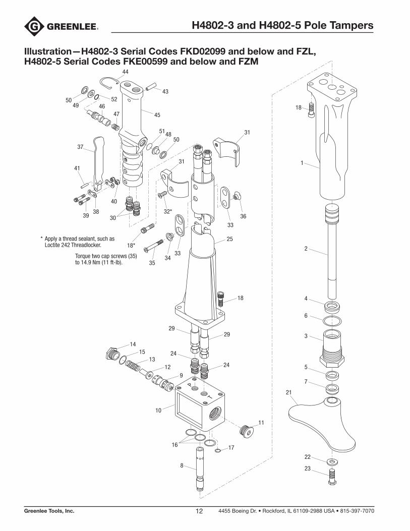
Illustration —H4802-3 Serial Codes FKD02099 and below and FZL, H4802-5 Serial Codes FKE00599 and below and FZM
P
T
23
22
7
21
5
3
6
4
2
1
18
17
11
8
16
10
1415
1312
9
25
18
29
24
24
29
33
3632*
18*
3534
33
41
3938
40
30
37
514850
4647
31
31
44
5049
4352
* Apply a thread sealant, such as Loctite 242 Threadlocker.
Torque two cap screws (35) to 14.9 Nm (11 ft-lb).
45

H4802-3 and H4802-5 Pole Tampers
Greenlee Tools, Inc. 4455 Boeing Dr. • Rockford, IL 61109-2988 USA • 815-397-707013
Parts List—H4802-3 Serial Code FKD02099 and below and FZL, H4802-5 Serial Code FKE00599 and below and FZM
UPC No. Key 78-3310- Part No. Description Qty
1 40293 50402932 Body, tamper ......................................................................... 1 2 40180 50401803 Ram ........................................................................................ 1 3 40377 50403771 Gland, packing (includes items 4–7) ...................................... 1 4* Seal, U-cup, .750 x 1.250 x .375 ........................................... 1 5* Seal, U-cup, .750 x 1.000 x .250 ........................................... 1 6* O-ring, 1.475 x 1.711 x .118–90 ............................................ 1 7* Wiper, rod, .750 x 1.125 x .281 .............................................. 1 8 40295 50402952 Shaft ....................................................................................... 1 9 40297 50402971 Spool ...................................................................................... 1 10 40296 50402961 Body, valve ............................................................................. 1 11 42072 50420722 Plug, 7/8–14 UNF SAE O-ring boss, socket head, steel ....... 1 12 40298 50402981 Stop, spool ............................................................................ 1 13 40299 50402991 Spring, compression, .330 x .500 x 1.250 ............................. 1 14 40300 50403005 Plug, 7/8–14 UNF SAE O-ring boss, hex head ...................... 1 15* O-ring, .755 x .949 x .097–90 ................................................ 1 16* O-ring, .750 x .937 x .094–70 ................................................ 3 17* O-ring, .375 x .500 x .062–70 ................................................ 1 18 Screw, cap, 5/16–18 x 1.000 socket head ............................. 9 21 40301 50403014 Foot, kidney-shaped .............................................................. 1 22 Washer, flat, .375 x .875 x .075 .............................................. 1 23 Screw, cap, 5/16–24 x 1.250 hex head ................................. 1 24 41341 50413413 Adapter, 1/4 M NPT x 9/16–18 M JIC .................................... 2 25 49536G 50495364 Tube assembly, handle (H4802-3) .......................................... 1 40386 50403861 Tube assembly, handle (H4802-5) .......................................... 1 29 40400 50404004 Hose, 3/8 x 38.75 with 9/16–18 JIC swivel at both ends (H4802-3) ...................................................... 2 40002 50400025 Hose, 3/8 x 30.00 with 9/16–18 JIC swivel at both ends (H4802-5) ...................................................... 2 30 41413 50414133 Adapter, pipe, 9/16–18 UNF SAE O-ring boss x 9/16–18 M JIC ................................................................. 2 31 40374 50403742 Guard, two-piece ................................................................... 1 32 Screw, cap, 1/4–20 x .750 flat head socket ........................... 2 33 40471 50404712 Washer, double ...................................................................... 2 34 40479 50404791 Washer ................................................................................... 2 35 41767 50417670 Screw, cap, 1/4–28 x 2.250 flat head socket ......................... 2 36 41768 50417680 Nut, 1/4–28 slotted flush countersink .................................... 2 37 40388 50403881 Lever, trigger .......................................................................... 1 38 41727 50417271 Plate, cover ............................................................................ 2 39 Screw, cap, #10–24 x 1.000 socket head .............................. 2 40 Nut, hex, #10–24, locking, elastic .......................................... 2 41 42090 50420902 Roll pin ................................................................................... 1 43 40427 50404272 Sleeve .................................................................................... 1 44 40428 50404282 Trigger lock ............................................................................ 1 45 Valve body / insulated handle ................................................ 1 46 40387 50403871 Control spool (open-center / closed-center) ......................... 1 47 40104 50401045 Spring, compression, .257 x .359 x .687 ............................... 1 48 Cap, end (replaced by 50489399) .......................................... 1 49 Washer, flat, .375 x .750 x .030 .............................................. 1 50 41455 50414551 Retaining ring, .750 ................................................................ 2 51* O-ring, .562 x .750 x .093–68 ................................................ 1 52* O-ring, .437 x .562 x .062–68 ................................................ 1
Repair Kits * 41120 50411204 Packing kit (includes items marked with an asterisk)

4455 Boeing Drive • Rockford, IL 61109-2988 • USA • 815-397-7070©2019 Greenlee Tools, Inc. • An ISO 9001 Company
USA Tel: 800-435-0786 Fax: 800-451-2632
Canada Tel: 800-435-0786 Fax: 800-524-2853
International Tel: +1-815-397-7070 Fax: +1-815-397-9247
www.greenlee.com