h.264 onvif ip camera - logicom security · before operating ip camera, please check the power...
TRANSCRIPT

User Manual H.264 OnVif IP Camera

1
Contents
Overview ...................................................................................................................................................... 2
Safety Instructions ..................................................................................................................................... 3
Application Fields ...................................................................................................................................... 4
Product Features ....................................................................................................................................... 4
Device Installation and Connection ......................................................................................................... 5
Appearance Description ............................................................................................................................ 5
Device Connection .................................................................................................................................... 7
Device Search Tool .................................................................................................................................. 10
ActiveX Control Setup .............................................................................................................................. 14
Webpage Configuration of IP Camera .................................................................................................. 15
Live .......................................................................................................................................................... 15
Parameter Setting ................................................................................................................................... 17
Display ..................................................................................................................................................... 17
Network .............................................................................................................................................. 20
Alarm .................................................................................................................................................. 28
Device ................................................................................................................................................. 30
System ............................................................................................................................................... 31
Date/Time .......................................................................................................................................... 32
Advanced ........................................................................................................................................... 34
Technical Parameters .............................................................................................................................. 38
Appendix 1Router Port Forwarding ....................................................................................................... 39
Appendix 2FAQ ......................................................................................................................................... 40

2
Overview Thank you for using our IP camera product series, which are integrative products developed for
the network video surveillance. On the basis of the newest solutions of Hisilicon, the product series
develop a media processing platform by integrating the capture, compression and network
transmission of audio and video on one board.With standard H.264 encoding algorithm, the products
ensure clearer and smoother video transmission. The remote users may implement real-time
monitoring by inputting the IP address or domain name of IP Camera on web browser.
The products can be applied for small- and medium-sized enterprises, government projects,
large-scale shopping malls, chain supermarkets, intelligent buildings, hotels, hospitals, schools, and
any other places requiring remote network transmission and monitoring. The productsare easy to be
installed and operated.
Before installation, please check if your product accessories are complete. If some parts are lost, please contact us immediately.
Note: IP Camera refers to Internet Protocol Camera.
Single click:Click with the left mouse button.
Double click: Click twice with the left mouse button.
Default IP address of IP Camera:192.168.1.168
IP Camera default Username:admin(lower case), Password:admin(lower case)
Default web port:80,Default media port:9988
Statement: The contents in the manual may be different from your current version. If you encounter any unsolved
problem during operation, please contact our technical support department or product supplier. The manual will be updated irregularly without prior notice.

3
Safety Instructions To correctly use the product and avoid danger or property loss, please carefully read this manual
before operation and keep properly for later reference. Use suitable power supply (attached or specified by the manufacturer). Do not use
unspecified power supply. If the device is malfunctioned, please contact authorized dealer or service center. Do not
disassemble or fix the device without permission (any problems caused by unauthorized change or repair are at your own risk).
Never let the device exposed in the rain or humid environment. Do not put the product in a humid place. If water accidentally intrudes into the device, please unplug the power supply and contact the local dealer immediately.
Do not put the device in a dusty place. Before operating IP camera, please check the power supply. Do not touch the optical components of image sensor. If necessary, use clean cloth and
alcohol to wipe away the dust. If IP camera is not in use, put on the dust-proof cover to protect the image sensor.
During operation, avoid water or any kind of liquid to flow into the camera. Do not focus against the strong light, such as lamplight or sunlight. Otherwise it will
cause excessive brightness and influence the service life of image sensor. Check the service environment and make sure that the device is used in normal working
environment. Improper replacement of batteries may cause malfunction of the product and accessories. It
is recommended for the users to change the batteries. If necessary, change with the same or equivalent type of batteries.

4
Application Fields IP camera is usually applied in large-scale shopping malls, supermarkets, schools, plants,
workshops, and other public places. As it has strong image processing capacity, IP camera can also be used in the environment requiring high definition of image, such as bank and traffic intersection. Refer to the following picture.
Product Features Hisilicon media processor with high performance and strong functions. Non-interlaced CMOS sensor Optimized H.264 video compression algorithms; Multi-stream transmission ensures high
definition image transmission on both narrowband and wideband. Support simultaneous connection of up to 5 video streaming. With Build-in Web Server, user may use standard IE browser to conduct real-time monitoring,
setting and management on the site. Support remote system upgrade. Support LAN and Internet. Support ONVIF protocol and GB28181 protocol. Support multiple network protocols, such as
TCP/UDP,IP,HTTP,DHCP,RTP,RTSP,FTP,SMTP,DNS,DDNS,NTP,ICMP,IGMP,ARP Support motion detection alarming function (user may set area and sensitivity) Support block alarm. Support privacy zone function. POE power supply function(optical) Support snapshot. Upload images by FTP or E-mail. Support automatic recovery function. It can be automatically connected in case of network
interruption. Note:The specifications of different products may be slightly varied.
Monitoring Center

5
Device Installation and Connection
Appearance Description
Model: EZ-IP7136IR
Items Descriptions ①Front cover It can prevent the IP camera from the irradiation of the sunlight. ②Rear cover It is fixed with the front cover. ③Set screw Fix the front cover and rear cover. ④Lens Lens of camera ⑤Infrared lamp Infrared LED lamp ⑥Ball and ball sleeve It is rotatable and used to adjust the angle of installation. ⑦Locknut Fix the ball sleeve and the base. ⑧Base Fix the device at the installation location. ⑨Fixing hole Fix with screws at the installation location.

6
Model: EZ-IP722812IR
Items Descriptions ① Front cover It can prevent the IP camera from the irradiation of the sunlight. ② Rear cover It is fixed with the front cover. ③Focusing lever Adjust the focal length of the camera. ④Lens Lens of camera ⑤Infrared lamp Infrared LED lamp ⑥ Ball and ball sleeve It is rotatable and used to adjust the angle of installation. ⑦ Locknut Fix the ball sleeve and the base. ⑧Base Fix the device at the installation location. ⑨ Fixing hole Fix with screws at the installation location.

7
Model: EZ-IP642812IR
Items Descriptions ① Transparent cover Protect the hemisphere ② Infrared lamp Infrared LED lamp ③ Lens Lens of camera ④ Black inner cover Fix the hemisphere ⑤ Adapter disc Connect tailing line and fix adjustment bracket
①
②
③
④
⑤

8
Model: EZ-IP6236IR
Items Descriptions
① Lens Lens of camera ② Infrared lamp Infrared LED lamp ③ Hemisphere It is rotatable and used to adjust the installation angle ④ Fixed guard Fix the position of the hemisphere. ⑤ Base Fix the device at the installation location. ⑥ Fixing hole Fix with screws at the installation location.
①
②
③
④
⑤
⑥
9
Device Connection
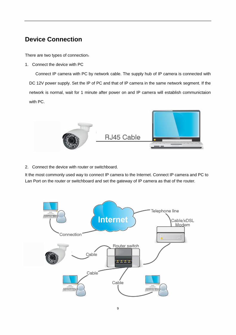
There are two types of connection:
1. Connect the device with PC
Connect IP camera with PC by network cable. The supply hub of IP camera is connected with
DC 12V power supply. Set the IP of PC and that of IP camera in the same network segment. If the
network is normal, wait for 1 minute after power on and IP camera will establish communictaion
with PC.
2. Connect the device with router or switchboard.
It the most commonly used way to connect IP camera to the Internet. Connect IP camera and PC to Lan Port on the router or switchboard and set the gateway of IP camera as that of the router.

10
Device Search Tool The software can detect the IP address of IP camera in the LAN. Firstly, install .exe file (Device Search) in the included CD by the following procedures.:
1. Double click the .exe file
2. Click [Next] to continue.
3. Select installation folder and click [Next] to continue.

11
4. Click [Install] to begin the installation.
12
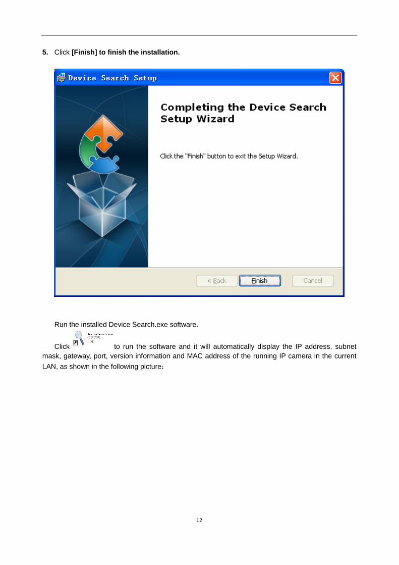
5. Click [Finish] to finish the installation.
Run the installed Device Search.exe software.
Click to run the software and it will automatically display the IP address, subnet mask, gateway, port, version information and MAC address of the running IP camera in the current LAN, as shown in the following picture:

13
If the searched IP address and PC IP address are not in the same network segment, user may
modify IP address, subnet mask, port number and other parameters of IP camera by using Device Search software.
In the DeviceSearch software, select a device to modify IP address and then input new IP address, subnet mask, gateway, port number and administrator password(default: admin). Click【Modify】 to change IP address of the device, as shown in the following picture:
Note:Default IP of IP camera is “192.168.1.168”, username is “admin”, password is “admin” , and

14
media port number is “9988”.
ActiveX Control Setup If the user visits IP camera with Internet Explorer for the first time, he has to install the plug-ins. For installing the plug-ins, it is necessary to set the browser security level. Enter menu [Tools/Internet Options/Security/Custom Level] and change “ActiveX controls and plug-ins” as “Enable” or “Prompt”, as shown in the following picture. For safety, after you view the image of IP camera, please reset the security setting in IE browser to default level.
Installation method of plug-in: Input IP address of IP camera in IE address bar to visit IP camera. The controls will be automatically loaded on IP camera.:
The plug-in installation dialogue box will be popped up. Click “Install” and the installation will be
completed automatically.

15
Webpage Configuration of IP Camera
Live Open Internet Explorer and input IP address of IP camera(http://192.168.1.168). The login
dialog box will appear. See the following picture:
User may select stream types and fluent level in the login interface.
Input user name(default: admin) and password (default: admin) and click “Login” to enter the Live
interface, as shown in the following picture.

16
Other buttons on the Live interface:
:Enter the device setting menu and set customized parameters of the device;
:Snapshot, file type, storage path, etc.;
:Log out and return to the login interface;
:It shows preview control buttons. From the left to the right, the names of buttons are play, stop, full screen, snapshot, start/stop recording, enable/disable talkback. :Enable/disable sound; Open/close video setting. Click “Local Setting” to pop up the following dialog box: User may set Record Path, Download Path, Snapshot Path, File Type and Interval for manual recording.

17
Parameter Setting
Display
Live
Click ,and enter the following interface(Live interface by default):
Channel Name:Name of IP camera Channel Display:Enable or disable. It may customize the display location. Time Display:Enable or disable. It may customize the display location. Flicker Control:50HZ, 60HZ or disable Transparency:Set the transparency of OSD background color.

18
Image Control
Click【Display】→【Image Control】to enter the following interface.:
IRCUT Mode:4 modes: GPIO Auto, Video Auto, Color Mode and Black & White Mode. IR-CUT Delay:Set IRcut delay switching time Image flip:Lens flip and angle flip Back light:Enable or disable the Back light. When enabled, there are three levels: low, middle and high. Back light compensation can compensate the darkness of the subject caused by shooting against the sunlight. In some application scenario, the field of view may contain a very bright background field, such as the door and window against the light, while the observed subject is surrounded by the bright field. In this case, the photo is gloomy and has no layering. The backlight compensation can be applied to solve the problem. 3D Noise Reduction:Enable (auto or manual) or disable the video noise reduction function. Default
setting is Auto. WDR:Enable or disable WDR function.
WDR is a technology that enables the camera to catch the image features with strong contrast. In short, DR (dynamic range) is the details of the bright part and dark part of image. The larger dynamic range shows richer layers and broader color space.

19
AGC:Adjust the level of AGC(low, middle and high)
White Balance:Auto, manual and indoor
Auto﹕Optimize according to the current lighting conditions and screen mode and calibrate
the video color of the camera.
Manual﹕Manually adjust red and blue gain of camera video
Indoor﹕Optimize according to the indoor environment and automatically calibrate the video
color of camera.
Shutter:It has auto mode and manual mode. Default mode is Auto.
Time exposure:Adjust exposure level of camera.
Privacy Zone
Click 【Display】→ 【Privacy Zone】 to enter the following interface:
Set privacy zone:
1. Click to enable privacy zone.
2. Press and drag left mouse button to select privacy zone (4 zones at maximum).
3. Click Save to make the privacy zone effective.

20
Delete:Click Refresh, select a privacy zone, click Delete, and click Save. The zone will be deleted.
Network
Network Setting Click【Network】→ 【Network Setting】to enter the following interface:
Type:DHCP or Static. Default type is Static.
Client Port:Client port of IPC
Web Port:Web port of IPC
Mobile Port:Connection port of mobile client
IP address:IP address of IPC
Subnet Mask: Subnet mask of IPC
Gateway:Default gateway of device
DNS1/DNS2:Configure DNS server
UPNP:Enable or disable UPNP function of device.
Note :When UPNP is enabled, user has to set the client port, web port and mobile port in the range
21
of 1024-65535. Client port is used for the connection of self-developed mobile client; Mobile port is
used for the connection of ASEE or ASEE+ client.
Video Streaming
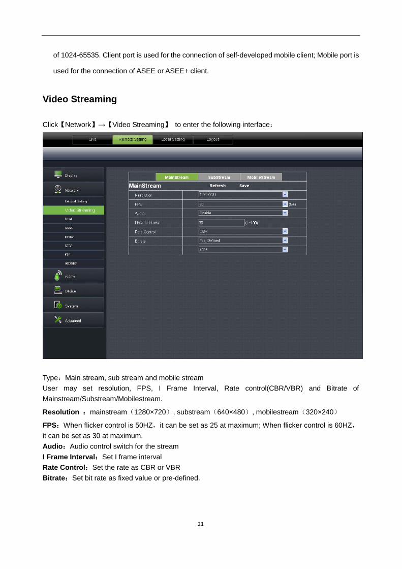
Click【Network】→【Video Streaming】 to enter the following interface:
Type:Main stream, sub stream and mobile stream User may set resolution, FPS, I Frame Interval, Rate control(CBR/VBR) and Bitrate of Mainstream/Substream/Mobilestream.
Resolution :mainstream(1280×720), substream(640×480), mobilestream(320×240)
FPS:When flicker control is 50HZ,it can be set as 25 at maximum; When flicker control is 60HZ,it can be set as 30 at maximum. Audio:Audio control switch for the stream I Frame Interval:Set I frame interval Rate Control:Set the rate as CBR or VBR Bitrate:Set bit rate as fixed value or pre-defined.

22
Click【Network】→【Email】 to enter the following interface:
:Email service setting. Apply this function with alarm function and the images
captured during alarming can be uploaded to E-mail server through network.
Enable Email: Disable or enable SMTP Port:Default value is 25(E-mail service port)
SMTP Server:Input E-mail server address Sender Email:Sender’s Email address
Sender Pwd:Password of sender’s Email Receiver Email:Receiver’s Email address
Interval:Select interval for sending Email(1min, 3min, 5min, 10min)
23
DDNS
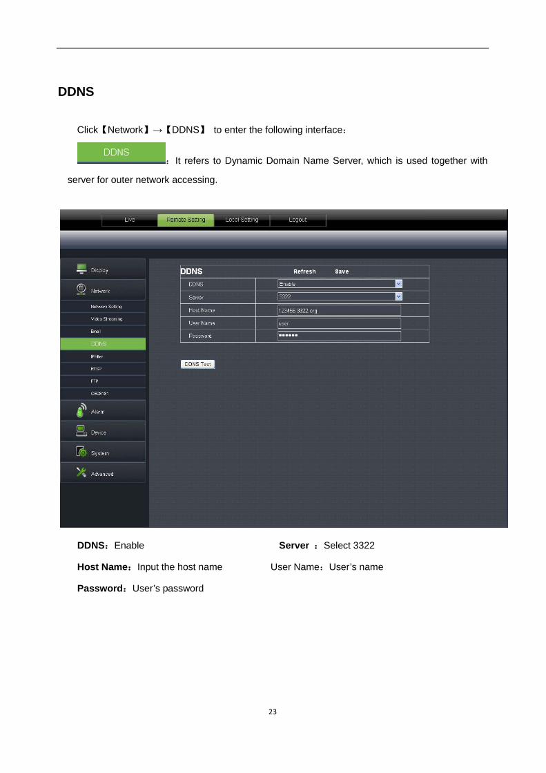
Click【Network】→【DDNS】 to enter the following interface:
:It refers to Dynamic Domain Name Server, which is used together with
server for outer network accessing.
DDNS:Enable Server :Select 3322
Host Name:Input the host name User Name:User’s name
Password:User’s password
24
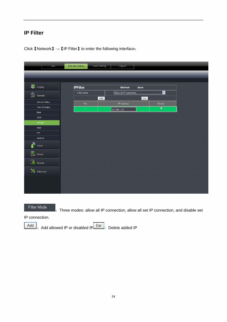
IP Filter
Click【Network】→【IP Filter】to enter the following interface:
:Three modes: allow all IP connection, allow all set IP connection, and disable set
IP connection.
:Add allowed IP or disabled IP :Delete added IP

25
RTSP
Click【Network】→【RTSP】to enter the following interface:
RTSP:Enable or disable. Default setting is “Enable”. If it is set as “Disable”, user may not find through ONVIF. RTSP Port: Default value is 554. The value can be changed in the range of 1024-65535. After modification, the device will be restarted. Description:
rtsp://IP:Port/A IP: IP address of the device Port:rtsp port of the device A:0,1,2……,(0 refers to main stream,1 refers to sub stream, 2 refers to mobile stream.)

26
FTP
Click【Network】→【FTP】to enter the following interface:
:FTP service setting. This function is applied together with alarming function. The captured
images or alarming recording can be uploaded to FTP server through network.
FTP: Enable or disable
User Name:User name for visitingFTP assword:Password for visiting FTP
FTP Server:Input FTP server address Port:FTP service port,default value is 21
Transfer Images:Click to transfer images Transfer Stream:Click to transfer stream

27
GB28181
Click【Network】→【GB28181】to enter the following interface: The device supports GB28181 protocol. Click the option “Open and Effective” to enable the
function. Set related registration information and click Save

28
Alarm
Motion
Click【Alarm】→【Motion】to enter the following interface:
Setting procedure:
1. Click to enable motion detection.
2. Click and drag left mouse button to select motion detection area.
3. Set motion detection sensitivity(Range:1-8. Larger number indicates higher sensitivity.)
4. It can link SMTP to send by Email
5. Click Save to make the setting effective.
When the motion alarm is triggered, the screen on Live interface will appear green character “M”.

29
Block Alarm Click【Alarm】→【Block Alarm】to enter the following interface: Alarm for blocking of camera lens It can link SMTP to send by Email.
30
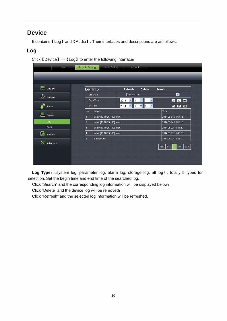
Device It contains【Log】and【Audio】. Their interfaces and descriptions are as follows.
Log Click【Device】→【Log】to enter the following interface: Log Type:(system log, parameter log, alarm log, storage log, all log), totally 5 types for
selection. Set the begin time and end time of the searched log. Click “Search” and the corresponding log information will be displayed below; Click “Delete” and the device log will be removed; Click “Refresh” and the selected log information will be refreshed.

31
Audio
Click【Device】→【Audio】to enter the following interface:
IPC audio switch Audio setting procedure:
Click “Enable Audio” and audio setting options appears. User may set the input volume and output volume in the range of 0-10. After setting, click Save to save the changed parameters.
System
System includes【Date/Time】,【Users】and【Info】. Refer to the following description.

32
Date/Time
Click【System】→【Date/Time】to enter the following interface:
In this interface, user may set Date/Time, including System Time, Date Format and Time Format. After setting, click Save.
The device also provides three kinds of automatic time synchronization:
DST:Click DST to enable DST function. The device will synchronize time according to the time offset.

33
NTP:Synchronize time with NTP server. Click NTP to enable NTP setting. Input NTP server
address, select time zone and click Save. The system will automatically synchronize time with NTP server.
Synchronize with computer time:Device will take computer as the time server to synchronize time.
Users Click【System】→【Users】to enter the following interface:
34
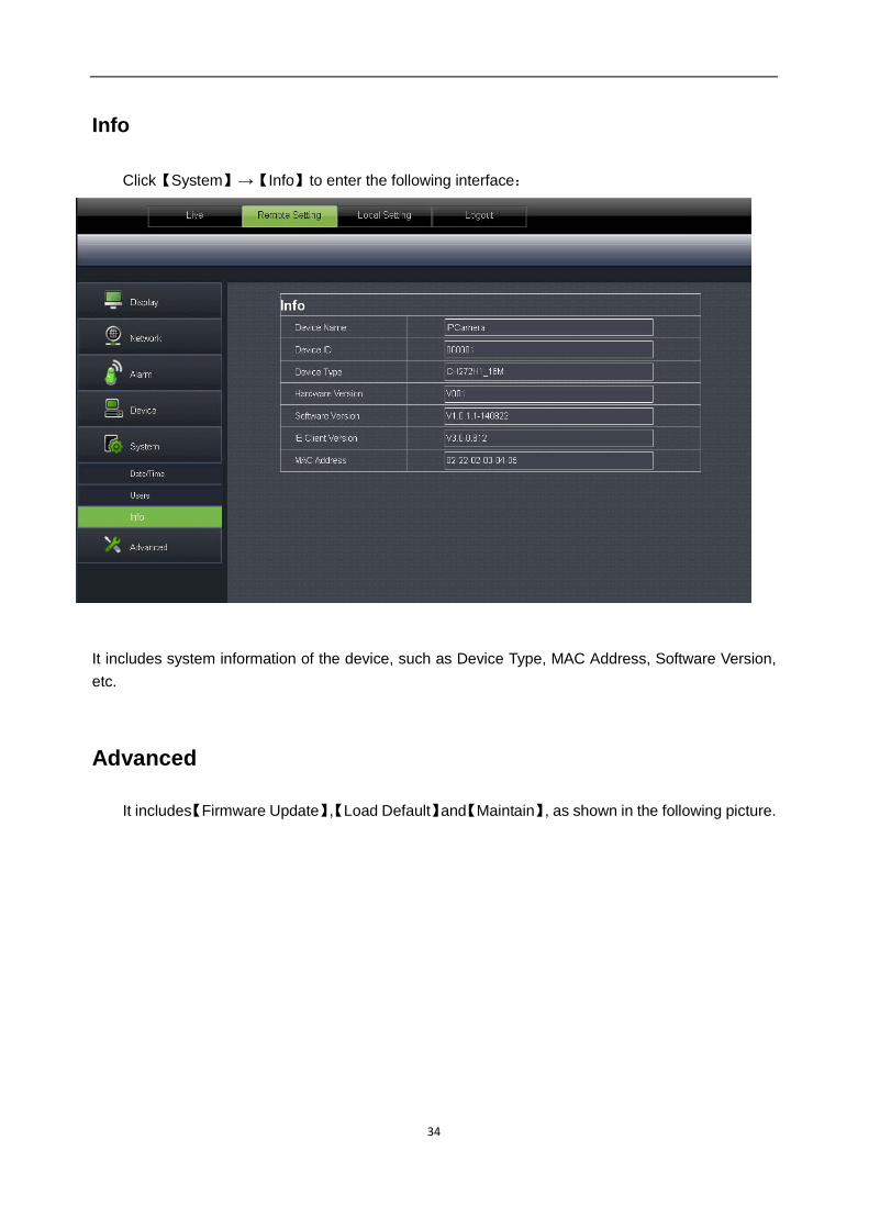
Info
Click【System】→【Info】to enter the following interface: It includes system information of the device, such as Device Type, MAC Address, Software Version, etc.
Advanced
It includes【Firmware Update】,【Load Default】and【Maintain】, as shown in the following picture.

35
Firmware Update
Click【Advanced】→【Firmware Update】to enter the following interface:
In “Firmware Update” option, user may click “Scan” to select update file, click Upgrade button
and the system will be upgraded automatically. If the upgrade file does not match the device, the update will fail.
Note:It will take about 5 minutes to update the firmware. Do not cut off power or network during
updating.

36
Load Default
Click【Advanced】→【Load Default】to enter the following interface:
In “Load Default” option, click the corresponding options and click Save to restore factory
settings for the selected options.

37
Maintain Click【Advanced】→【Maintain】to enter the following interface:
In “Maintain” interface, user may set periodically reboot or manual reboot.

38
Technical Parameters
Items Descriptions
100W 130w 200w
Camera
Image Sensor CMOS Sensor
Video Format P/N adaptive control
Minimum luminance 0.08Lux @(F1.2,AGC ON) ,
0 Lux with IR 0.03Lux @(F1.2,AGC ON) ,0 Lux with IR
Shutter speed 1/25s ~ 1/20,000s
Day/night switch mode IR auto switch
Compression
Standard
Video compression standard H.264
Video compression rate 64kbps-8Mbps
Triple stream Yes
Image
Max. resolution 1280×720 1280×960 1920×1080
Image frame rate
50 Hz:
720P/25fps(1280×720)
VGA/20fps(640×480)
QVGA/5fps(320×240)
60 Hz:
720P/30fps (1280×720)
VGA/20fps (640×480)
QVGA/5fps(320×240)
50 Hz:
960P/25fps(1280×960)
VGA/20fps(640×480)
QVGA/5fps(320×240)
60 Hz:
960P/30fps(1280×960)
VGA/20fps(640×480)
QVGA/5fps(320×240)
50 Hz:
1080P/25fps(1920×1080)
VGA/20fps(640×480)
QVGA/5fps(320×240)
60 Hz:
1080P/30fps(1920×1080)
VGA/20fps(640×480)
QVGA/5fps(320×240)
Image Image setting Adjust saturation, brightness and contrast through client software of web browser.
Network Protocol TCP/IP、UDP、RTP/RTCP、RTSP、HTTP、SMTP、DNS、DDNS、DHCP、FTP、NTP、PPPOE、UPNP
Port Data interaction port 1 RJ45 10M / 100M Ethernet interface
General
Specifications
Grade of waterproofing IP66
Working environment -10 °C ~ 60 °C (14 °F ~ 140 °F) below 90%RH(no condensation)
Power supply 12 VDC ± 10%, PoE

39
Appendix 1Router Port Forwarding
If user wants to remotely visit IP Camera monitoring image through internet, he has to open web port and client port of IP Camera. Take Cisco router as an example:
IP address of IPC is 192.168.1.168, web port is 8000 and client port is 9988.。

40
Appendix 2FAQ
◆ IE cannot load and install plug-ins. Possible cause:IE security level is set too high. Solution:Set IE security level to the minimum level.
◆ After updating, user cannot visit IP Camera through IE.
Solution:Clear IE cache. Specific steps: Open IE Tools, open Internet option, click “delete file” button in the 2ndoption (temporary Internet files), click “delete all offline contents”, and click OK. Log in IP Camera again.
◆ Why cannot visit IP Camera through IE?
Possible cause 1:Network fault Solution:Connect PC to internet and test if network access is normal. Check if there are any cable problems or network problems caused by PC virus until PC can ping each other. Possible cause 2:IP address is occupied by other devices. Solution:Disconnect IP camera and network and connect IPC and PC and set device IP address. Possible cause 3:IP address is located in different subnet. Solution:Check setting of IP address, subnet mask address, and gateway. Possible cause 4:The physical address of the network conflicts with IP camera. Solution:Change physical address of IP camera. Possible cause 5:Web port is changed. Solution:Contact network management to obtain the corresponding port information.
◆ PC client cannot be connected to the frontend video Solution:Check if IP camera video can be normally viewed in IE, if the device can be searched by PC client software, and if the device parameters on PC client are set correctly. ◆ Mobile client cannot be connected to the frontend video Possible cause 1:Mobile stream is not enabled Solution:Enable mobile stream. Possible cause2:Mobile port number is not input correctly. Solution:The port number of our mobile client software is 9988 and that of the third-party client is 8800. Possible cause3:Device video streams connections exceed the maximum limitation. Solution:Reduce the connections of device video streams.