h assessment of technologies to provide ktended sludge ... · pdf filepnnl13048 uc-721 h...
TRANSCRIPT

PNNL13048
UC-721
h Assessment of Technologies
to provide ktended Sludge Retrieval
from Underground Storage Tanks
at the Hanford Site
J. A. Bamberger
July 2000
Prepared for the U.S. Department of Energy
under Contract DE-AC06-76RL0 1830
Pacific Northwest National Laboratory
Riehlan& Washington 99352
. ........ ~— ——- - --.- -.--<-.-..- TT---- ., ::,--= —-- —--7=--- z: -. --


DISCLAIMER
This report was,.prepared as an account of work sponsoredby an agency of the United States Government. Neitherthe United States Government nor any agency thereof, norany of their employees, make any warranty, express orimplied, or assumes any legal liability or responsibility forthe accuracy, completeness, or usefulness of anyinformation, apparatus, product, or process disclosed, orrepresents that its use would not infringe privately ownedrights. Reference herein to any specific commercialproduct, process, or service by trade name, trademark,manufacturer, or otherwise does not necessarily constituteor imply its endorsement, recommendation, or favoring bythe United States Government or any agency thereof: Theviews and opinions of authors expressed herein do notnecessarily state or reflect those of the United StatesGovernment or any agency thereof.

DISCLAIMER
Portions of this document may be illegiblein electronic image products. Images areproduced from the best available originaldocument.
—— -. —---- .-, ----- rm. .. .-+,.,>- ---- —-— -

Acknowledgments
The extended sludge retrieval activities are part of the Retrieval Process Development andEnhancements (RPD&E) Project under direction of the US Department of Energy Office of Science andTechnology Tanks Focus Area. The purpose of the Retrieval Process Development and EnhancementsProject is to undemtand retrieval processes including ongoing and existing technologies, gather data onthese technologies, and relate the data to specific tank problems such that end users have requisitetechnical bases to make retrieval-and closure decisions. This work was conducted in conjunction withEnc Pacquet and John Garliel~ Numatec Hanford Company, and Craig Shaw, Cogema EngineeringCorp.
...Ill
-.—..-—— .. ---- ~..... . .. .7---- -,.. - r nT-. . . . . . . . . . . . . . . . >. . . . . “.,.C=-n>---— -,---- . . ..-.

Summary
The purpose of this study was to identify sludge mobilization technologies that can be readilyinstalled in double-shell tanks along with mixer pumps to augment mixer pump ope~on when mixerpumps do not adequately mobilize waste. The supplementary technologies will mobilize sludge that mayaccumulate in tank locations out-of-reach of the mixer-pump jet and move the sludge into the mixer-pump range of operation. The identified technologies will be evaluated to determine if their performancesand configurations are adequate to m~t requirements developed for enhanced sludge removal systems.
The study proceeded in three parallel paths to identify technologies thaE 1) have been previouslydeployed or demonstrated in radioactive waste tanks, 2) have been specifically evaluated for their abilityto mobilize or dislodge waste simukmts with physical and theological properties similar to thoseanticipated during waste retrieval, and 3) have been used in sirniku industrial conditions, but notspecifically evaluated for radioactive waste retrieval.
TechnologiesEvaluated
Technologies were identdkd that have already been deployed or are being developed for deploymentto remediate radioactive waste tauks. These technologies include
Pulsed AirPulsating Mixer Pump
Fluidic Pulse-Jet MixingC-106 SluicerBorehole-Miner Extendible-NozzleWaste-Retrieval End Effecter
High-Pressure Scarifier
Flygt Mixer.
All of the technologies, with exception of the Flygt mechanical mixer, are based on jet mixing. Thejet fluid is air, slurry, or water. The jet pressure, duration, and pulse rate vary based on the technology.Several of the technologies are very similar. The pulsating mixer pump and fluidic pulse-jet mixing bothcreate jets by using suction to draw slurry from the tank into a tube and pressure to expel the fluid jet backinto the tank. The C-106 sluicer and the borehole-miner extendible-nozzle are both based on sluicinghowever, the borehole miner operates at a higher pressure [20.7 MPa (3000 psi)] than the C-106 sluicer[2.07 MPa (300 psi)] and has an increased jet range based on the extension of the nozzle away from themast using its extendible arm. The waste-retrieval end effecter and the high-pressure scarifier are bothbased on scarification – using a high-pressure, low-flow-rate jet to Ilacture and erode solids, with thehigh-pressure scdler operating at significantly higher pressure [379 MPa (55,000 psi)] than the waste-retrieval end effecter [68.9 or 207 MPa (10,000 or 30,000 psi)].
The performance of additional technologies have been evaluated for their ability to mobilize ordislodge a specific type of simulated waste such as sludge, hard pan, or salt cake. Other technologieshave been identifkd as promising based on industrial application in other tank-cleaning environments.
v
Criteriafor Evaluation
To compare the technologies, their physical and operating characteristics have been summarized.Iterns addressed include the operating principal, ability to dislodge waste forms, and other operatingcharacteristics. The technologies are ordered by jet pressure from low to high. Then the technologies arerated with respect to meeting criteria developed for enhanced sludge removal performance. Performanceis grouped into three categories: the technology either meets the criteriz has the ability to be modified tomeet the criteri% or is not able to be readily modified to meet the criteria.
Specific criteria include
● The device shall assist waste mobilization in dead areas.
● The device shall enhance mobilization for a radius of 3.0 m (10 ft) in waste with a shear strengthof 1.96 kPa (41 lbf7ft2).
To put the shear strength value [1.96 kl?a (41 lbf/ft2)] in perspective, it is compared withsimulants developed at Pacific Northwest National Laboratory to model waste properties (Powellet al. 1997, Bamberger et al. 1998). A 50% kaolin, 13% plaster, 37% water simulant developedto model sludge had a shear strength of 2.5 kpa (52 Ibflf?), just slightly higher than the targetselected for extended sludge retrieval equipment. A 22.5910kaolin, 40% plaster, 37.5?Z0watersimukmt developed to model hard pan had a shear strength of 150 kpa (3133 lbf/ft2). A salt cakesimukmt (84% dynamate fertilizer in water) had a compressive strength of 19 MPa (396,825lbf/ft2). With respect to the types of simuhmt,.sdeveloped for evaluation of waste remediationequipmen~ the shear strength value of 1.96 kPa (41 lbfKt2)selected as the basis for evaluation ofextended sludge retrieval is very low.
. The device shall pass through a 12.7- to 15.2-cm (5-to 6-in.)dkrneter riser.’
TechnologySummary
Based on the evaluation Criteriz one technology, the borehole-miner extendible-nozzle, has theproven ability to meet key primary requirements. The borehole-miner extendible-nozzle can mobilizesludge and extremely hard waste at a distance of up to and greater than 3 m (10 ft). The arm extension of3 m (10 ft), and its ability to move back and forth can be used to sweep waste from collection pilesdeposited by the mixer pump back into the mixer pump path or toward the retrieval pump inlet. Thecurrent borehole-rniner extendible-nozzle mast is larger than the 15.2-cm- (6-in.-) diameter riserhowever, this parameter could be readily modifkd for the application.
1Larger risers [0.30, 0.61, and 1.1 m (12, 24, and 42 in. in diameter)] maybe available for extendedsludge retrieval system deployment in specific tanks; however, for this study the 15.2-cm (6-in.) riser wasselected as the evaluation criteria because it represents the most prevalent riser size for systemdeployment.
vi

Two other technologies, the pulsating mixer pump and fluidic pulse-jet mixing will readily fit througha 15.2-cm (6-in.)diameter riseq however, these technologies need to be evaluated to determine theeffective cleaning radius of their jets and the range of shear strengths of sludge that the jets can dislodge.
vii
.—-,.. .,-, . .-r.r.. —-— ... . . ,. -,,, ,., .,5V - .:.


Acknowledgments...
................................................................................................................................ .......111
summary ....................................................................................................................................... ................ v
Technologies Evduati ............................................................................................................................vCriteria for Evaluation .............................................................................................................................vi
Technology SUmmary ..............................................................................................................................vi
1. Introduction ........................................................................................................................................ 1.1
1.1 Background .................................................................................................................................... 1.1
1.1.1 Radioactive Waste at Hanford ............................................................................................... 1.1
1.1.2 Waste Treatment and Immobilization Approach ................................................................... 1.2
1.2 Scope ................................................................................................................................. ............. 1.2
2. Conclusions and Recommendations ..................................................................................................2.1
2.1 Technologies Identified ..................................................................................................................2.1
2.1.1 Pulsed-Air Mixer ....................................................................................................................2.2
2.1.2 Pulsating Mixer Wmp ............................................................................................................2.22.1.3 Fluidic Pulse-Jet Mixing ........................................................................................................2.2
2.1.4 C-106 Sluicer .........................................................................................................................2.22.1.5 Borehole-Miner Extendible-Nozzle .......................................................................................2.3
2.1.6 Waste-Retrieval End Effecter ................................................................................................2.32.1.7 High-Pressure Scarifier ..........................................................................................................2.3
2.1.8 Flygt Wxen ...........................................................................................................................2.32.2 Technology Comparisons ..............................................................................................................2.3
2.3 Rwomen&ons ..........................................................................................................................2.4
3. Waste Feed Delivery System .............................................................................................................3.l3.1 Waste Tanks ...................................................................................................................................3.l3.2 Tank Configurations ......................................................................................................................3.3
3.2;13.2.23.2.33.2.43.2.53.2.63.2.73.2.83.2.93.2.10
Tanks i02- and 107-AN .........................................................................................................3.3
Tanks 103-,104-, and 105-AN and 10l.AW .........................................................................3.7Tanks 102- and 104-AP .......................................................................................................3.llTank l&D ........................................................................................................................3.llTank 108.N ........................................................................................................................3.l 1Tank 102-AY .......................................................................................................................3.11Tanks 101- and 102-AZ .......................................................................................................3.11
Tanks 102-, 104-, ~d 106-C................................................................................................3.15
Tank 101-SY ........................................................................................................................3.15
Tank 102-SY ....................................................................................................................3.15
3.3 Retrieval Scenarios ......................................................................................................................3.21
3.3.1 Retrieval of Waste horn Tank 105.N ................................................................................3.2l.3.3.2 Retrieval of Waste from the AY and AZ Tti ...................................................................3.2l3.3.3 Retrieval System Configurations .........................................................................................3.2l
ix
4. Selection Guidance for Devices to Enhance Sludge Removal ...........................................................4.l4.14.24.34.44.54.64.74.8
htioduction ....................................................................................................................................4.lFunctions ........................................................................................................................................4.2Requirements .................................................................................................................................4.2btetiaces ........................................................................................................................................4.3Constraints .....................................................................................................................................4.3*mtiond N* ..........................................................................................................................4+4Assumptions ...................................................................................................................................4.5Updated Derived Requirements .....................................................................................................4.5
5. Evaluation of Enhanced Sludge Removal Technologies ...................................................................5.l5.1 Criteria for Evaluation ...................................................................................................................5.l
5.1.1 Primary Requirements ............................................................................................................5.l5.1.2 Secondary Requirements ........................................................................................................ .5.1.3 Safety Requirements ..............................................................................................................z..5.1.4 Design - Construction – Installation Details .........................................................................5.3
5.2 Evaluation Matrix ..........................................................................................................................5.35.3 Technology Evaluation ..................................................................................................................5.35.4 Technology hnmary ....................................................................................................................5.3
6. Deployed Technologies for Enhanced Sludge Removal ....................................................................6.l6.1 Fluidic Pulse Jet Mixing ................................................................................................................6.l
6.1.1 Pulse-jet Mixer Operating Cycle ...........................................................................................6.26.1.2 Pulse-Jet Mixer System Components .....................................................................................6.2
6.1.3 Pulse-Jet Mixer Performance .................................................................................................6.36.1.4 Pulse-Jet Mixer Deployment for Enhanced Sludge Retievd ................................................6.4
6.2 Borehole-Miner Extendible-Nozzle Sluicer ...................................................................................6.46.2.1 Extendible-Nozzle @ration .................................................................................................6.46.2.2 Extendible-Nozzle System Components ................................................................................6.46.2.3 ORNL Conllguration Extendible-Nozzle Wei@t ..................................................................6.76.2.4 Extendible-Nozzle Operating Experience and Petiommce ..................................................6.86.2.5 Extendible-Nozzle Deployment for Enhanced Sludge Removal ...........................................6.8
6.3 C-106 Sluicer ................................................................................................................................. 6.9
6.3.1 Sluicer System Components ..................................................................................................6.96.3.2 Sluicer Operation .................................................................................................................6.l26.3.3 Sluicer Performance .............................................................................................................6.l26.3.4 Sluicer Deployment for Enhanced Sludge Removal ............................................................6.14
6.4 Pulsed-Air ~xer ..........................................................................................................................6.l46.4.1 Pulsed-Air Mixer Operation .................................................................................................6.l46.4.2 Pulsed-Air Mixer System Components ................................................................................6.l56.4.3 Pulsed-Air Mixer Operating Experience and Petio.ce ..................................................6.l86.4.4 Pulsed-Air Mixer Deployment for Enhanced Sludge Removal ...........................................6-18
6.5 Waste-Retrieval End Effecter ......................................................................................................6.l86.5.1 Waste Retrieval End-effecter O~r~ion ..............................................................................6.2O6.5.2 Waste-Retxieval End-Effecter System Componen~ ............................................................6.2O
A
6.5.3 Waste-Retrieval End-Effecter Performance .........................................................................6.20
6.5.4 Waste-Retrieval End-Effecter Deployment for Enhanced Sludge Removal .......................6.216.6 Pulsating Mixer Pump ..................................................................................................................6.21
6.6.1 Pulsating Mixer Pump Components and Operation .............................................................6.21
7. Demonstrated Technologies for Enhanced Sludge Removal .............................................................7.1
7.1 High-Pressure Sctier ..................................................................................................................7.l7.2 Advanced Sluicing System ............................................................................................................7.2
7.3 Vehicle Deployed Sluicer ..............................................................................................................7.2
7.4 Flygt Mixers .................................................................................................................................. .7.3
8. Industrial Technologies for Enhanced Sludge Removal ....................................................................8.1
8.1 Literature Survey of Mixing Techniques for Double-Shell Tanks ................................................ 8.1
8.2 Consilium Gun Clean ..................................................................................................................... 8.1
9. References .......................................................................................................................................... 9.1
xi

I?@mes
Figure 3.1Figure 3.2Figure 3.3Figure 3.4Figure 3.5Figure 3.6Figure 3.7Figure 3.8Figure 3.9
Tank farms and waste retrieval pipeliie to privatization contractor site .................................3.lCross-section of Tank 102.~ ................................................................................................3.3Cross-section of Tank 107.~ ................................................................................................3.7Riser locations for Tank 103-AN ............................................................................................3.8Riser locations for Tank 104-AN ............................................................................................3.9Riser locations for Tank 10l.AW ..........................................................................................3.lOTank 102-A.Priser locations ..................................................................................................3.I2Tank 104-AP riser locations ..................................................................................................3.l3Tank 102-AZ riser lwtions ..................................................................................................3.l4
Figure 3.10 Tank 102-C riser locations ..................................................................................................3.16
Figure 3.11 Tank 104-C riser locations ...................................................................................................3.l7Figure 3.12Figure 3.13Figure 3.14Figure 3.15Figure 3.16Figure 3.17Figure 3.18Figure 3.19Figure 3.20Figure 3.21Figme 3.22Figure 3.23
Figure 4.1
Figure 6.1Figure 6.2Figure 6.3Figure 6.4Figure 6.5Figure 6.6Figure 6.7Figure 6.8Figure 6.9
Tank 106-C riser locations ..................................................................................................3.l8Tank 101-SY riser locations ................................................................................................3.l9T* 102-SY riser locations ................................................................................................3.20Legend for waste retrieval concepts ....................................................................................3.22C tank waste retrieval approxh ...........................................................................................3.22AN tank waste retrieval coti~ation .................................................................................3.23AN tank waste retrieval cotil~tion .................................................................................3.24M tank waste retrieval conf@ration .................................................................................3.25AW tank waste retrieval coti=wation ................................................................................3.26SY tank waste retrieval configuration .................................................................................3.27Waste retrieval configuration for AY tanks before and after C tank sluicing .....................3.28AZ tank waste retrieval conf@ration .................................................................................3.29
lSxample of mixer pump effective cleaning radius GcR) .......................................................4.2
pulse jet operating phm= ........................................................................................................6.lJet pump configuration and operation .....................................................................................6.3
Extendible nozzle deployment and conilguration ...................................................................6.5Tank 106-C process flow sh&t ..............................................................................................6.lOC-106 sluicer system cofi~tion .......................................................................................6.l 1Planned sluicer o~tion .......................................................................................................6.l2Pulsed-air bubble formation, growth, and coalescence. Courtesy of Pulseair Systems, Inc.6.15Dual-plate pulsed-air mixer confi~tion .............................................................................6.l5Multiple mixer plates deployed via the inverted umbrella approach .....................................6.l7
Figure 6.10 Sludge retrieval end effwtor ................................................................................................6.l9Figure 6.11 Gunite scarifying end effecter .............................................................................................6.l9Figure 6.12 Pulsating monitor system tested at PM ...........................................................................6.22Figure 6.13 Diagram and dimensions of jet footprint created by pulsating mixer on tank floor . ...........6.24
Figure 7.1 Lightweight scarifier deployed by light duty utility arm dislodging salt-cake simulant .........7.1Figure 7.2 Vehicle with sluicer *chent ...............................................................................................7.3
xii

Figure 7.3 M&lified Flygt mixers constructed for Tanlc 19......................................................................7.4
Figure 8.1 Gunclean nozzle configurations .............................................................................................. 8.2

Tables
Table 2.1 Comparison of the waste mobilization technologies ................................................................2.5Table 2.2 Comparison of the enhanced removal technologies with the acceptance criteria .....................2.8
Table 3.1 Tanks with waste to be retrieved during Phase 1 privatization .................................................3.2
Table 3.2 Remediaton equipment required for each tank .........................................................................3.4
Table 4.1 Updated derived requirements for auxiliary solids mobiHon ..............................................4.5
Table 5.1 Matrix for technology comptison ............................................................................................5.4Table 5.2 Criteria for technology selwtion ...............................................................................................5.5Table 5.3 Compaison of the waste mobilization technologies ................................................................5.6Table 5.4 Comparison of the enhanced removal technologies with the acceptance criteria .....................5.9
xiv
Table 6.1 Extendible-nozzle sp*tictions ...............................................................................................6.6Table 6.2 History of Tank 106-C sluicing .sfe~ ................................................................................6.l3

1. Introduction
Hanford needs enhanced sludge mobilization methods to retrieve sludge that is beyond the effectivecleaning radius (.ECR)of the baseline pair of long-shaft mixer pumps planned for mobilization of theradioactive waste stored in 23-m- (75-ft-) diameter double-shell tanks. Other sites, such as the SavannahRiver Site and West Valley, which also use mixer pumps in large volume tanks, may also need toimplement a plan for enhanced sludge mobilization. At Hanford this study was performed incollaboration with the River Protection Project (RPP) team to support waste feed stream treatment andimmobilization.
1.1 Background
The River Protection Project Phase 1 project is the U.S. Department of Energy’s (DOE’s) plan toassure treatment of Hanford tank waste. During the lo-year minimum+xderquantity perid the facilityis expected to process approximately 10% of the Hanford tank waste by mass and 20% to 25% byradioactivity.
1.1.1 Radioactive Waste at Hanford
Approximately 204,411 m3(54 million gallons) of highly radioactive wastes are stored in 177underground tanks, including 149 older single-shell tanks, at the Hanford Site in Washington State. Thatwaste, which was derived from production of plutonium for the nation’s nuclear defense program, hasbeen accumulating at Hanford since 1944. The waste poses a serious safety concern to the public and tothe environment. That risk is growing because most of the single-shell tanks have exceeded their designlife. Sixty-seven of the single-shell tanks are known to have leak~ and several additional tanks arebeing investigated for potential leaks. Nearly 3785 m3 (1 million gal) of the tank waste has spilled intothe soil of the vadose zone bdow the tanks since the first leak occurred. Recent information has indicatedthat tank waste radionuclides have moved through the vadose zone and now have reached thegroundwater that flows under the Hanford Site, which migrates to the Columbia River.
DOE is taking active measures to reduce the chance of additional tank leaks. However, it is notpossible to predict when the next tank will lealGand with passage of time, even the newer, safer double-shell tanks are approaching the end of their design lives. Removal of the waste from the tanks, treatmen~and immobilization as an inert waste form will constitute a lasting solution to the problem. DOE, theU.S. Environmental !%otectionAgency, and the Washington State Department of Ecology have enteredinto an enforceable compliance agreement setting forth milestones for cleanup of the tank waste. DOE,State regulatory agencies, and stakeholders view the tank waste cleanup as one of their top priorities.
1.1
-.,.—-.. ,., .. . .>--,-m ., .,<.,.. T-77-,? ., -,, ,, ., ..:..,, - !,. ., ------ ,: . . m :-- 7, P,c —— —.--~, - ,-. _. ,.

1.1.2 Waste Treatment and Immobilization Approach
In September 1996, DOE entered into contracts with two con~ctor teams for Phase 1 of the RPPprivatization project. At the time of contract award, the contracts for RPP Phase 1 were structured intotwo parts: a 20-month Part A, ending in mid-1998 and an optional Part B, planned for approximately 10to 14 years. The purpose of Part A was to evaluate the technical, operational, regulatory, business, andfinancial elements required by pnvatized facilities that would provide treatment and immobilizationservices on a fixed-unit-price basis. Under the original RPP Phase 1 contracts, Part B was a period,scheduled to begin in rnid-1998, in which the authorized contractor(s) would fully finance, design,construc~ operate, and deactivate waste treatment plants on a fixed-price basis. Based on a detailedreview of the work products prepared by both contractors (as required by Part A of the contract), DOEdecided to restructure Part B of the contract and to authorize only one contractor, to proceed to the designphase of Phase 1. DOE concluded that the contractor proposal contained a viable conceptual facilhydesign with robust technologies that have been effectively demonstrated at other sites and that thecontractor would be able to meet contractual requirements for design, construction, and operations in thebalance of Phase 1.
In April 2000 DOE made a decision to discontinue the privatization approach for RPP aftercompleting a review of the April 2000 deliverables submitted under the RPP privatization contract.Currently the DOE Office of River Protection is seeking competitive proposals from the private sector todesign and construct a treatment and immobilization plant for the RPP at the Hanford Site near Richland,Washington.
1.2 Scope
This objective of this study was to support RPP’s ability to deliver the Phase lB waste feed stream forwaste treatment and immobilization. Hanford needs enhanced sludge mobilization methods to retrievesludge that is beyond the effective cleaning radius (ECR) of the baseline pair of long-shaft mixer pumps.
The scope of this task is to identify potential systems that can be installed in the double-shell tanksalong with the mixer pumps, when needed to mobilize the remaining sludge. The systems will beevaluated based on this limitation incorporating knowledge of existing tank requirements and constrains.The systems will be identified and prioritized to determine whether they can be operated concurrently intandem with mixer pumps or sequentially after mixer pumps have stop~ to move settled solids intoareas influenced by mixer pumps. These auxiliary systems will further mobilize waste not under theinfluence of the mixer pumps or tranlocate the waste to areas of the tank that are influenced by the mixerpumps. This assessment will be integrated with similar RPP investigations. The final objective is tosummarize results in a report recommending one or several types of “small systems” that can be installedin the tanks along with the mixer pumps when needed to mobilize the remaining sludge.
1.2

2. Conclusions and Recommendations
The purpose of this study was to identify sludge mobilization technologies that can be readilyinstalled in the double-shell tanks along with the mixer pumps, when mixer pump operation does notadequately mobilize the waste. The supplementary technologies will mobilize sludge that mayaccumulate in tank locations out-of-reach of the mixer pump jet. This study assessed the potential of thetechnologies to meet requirements developed for enhanced sludge removal systems.
The study proceeded in three parallel paths”to identify technologies thac 1) have been previouslydeployed or demonstrated in radioactive waste tanks, 2) have been specifically evaluated for their abilityto mobilize or dislodge waste simukmts with physical and theological properties similar to thoseanticipated during waste retrieval, and 3) have been used in similar industrial conditions, but notspecifically evaluated for radioactive waste retrieval.
2.1 TechnologiesIdentified
A series of technologies were identified that have already been deployed or are being developed fordeployment to remediate radioactive waste tanks. These technologies include:
●
●
●
●
●
●
●
●
Pulsed AirPulsating Mixer PumpFluidic Pulse-Jet MixingC-106 Sluicer
Borehole-Miner Extendible-NozzleWaste-Retrieval End EffecterHigh-Pressure Scarifier
Flygt Mixers.
All of the technologies with the exception of Flygt mixers are based on jet mixing. The jet fluidis either air, slurry, or water. The operating parameters, jet pressure, duration and pulse rate, vary, basedon the technology. Several of the technologies are very similar. The pulsating mixer pump and fluidicpulse-jet mixing both create jets by using suction to draw slurry fkom the tank into a tube and followed bypressure to expel the fluid jet back through the tube into the vessel. The C-106 sluicer and the borehole-miner extendible-nozzle are both based on sluicing however, the borehole miner operates at a higherpressure and has an increased range-of-influence from its extendible arm extension. The waste-retrievalend effecter and the high-pressure scariiier are both based on scarification, with the high-pressurescarifier operating at significantly higher pressure than the waste-retrieval end effecter. In contras~ theFlygt mixer uses an electrically-powered propeller sumounded by a close-fitting shroud. The propellercreates a turbulent fluid jet.
The performance of additional technologies has been evaluated for each technology’s ability tomobilize or dislodge a specific type of simulated waste such as sludge, hard pan, or salt cake. Other
2.1

technologies have been identified as promising based on industrial application in another tank cleaningenvironment.
2.1.1 Pulsed-Air Mixer
The pulsed-air mixing technique utilizes sho~ discrete pulses of air or inert gas to produce largebubbles near the tank floor. Air pulses injected beneath horizontal circular plates positioned just abovethe tank floor produce the bubbles. These bubbles rise toward the liquid surface and induce mixin& thepulse frequency, duration, gas pressure, and plate sequencing are controlled to create a well-mixedcondition within the tank. In 1999, Oak Ridge National Laboratory (ORNL) deployed a pulsed-air mixer
in Tank W-9 to mix waste solids and accelerate settling of >100-pm-diameter particles.
2.1.2 Pulsating Mixer Pump
Pulsed-jet mixers such as the pulsating mixer pump have a tube or nozzle that extends to the bottomof the tank. During operation, a vacuum is created pulling fluid into the tube rmd into an accumulatorvessel. NexL pressure is appli~ and the fluid is forced back into the tank out through the bottom of thetube. As the process fluid emerges from the nozzle, the jet suspends solids and induces circulationpatterns. In 1998, pulsating monitor technology, consisting of a jet mixer powered by a reciprocating airsupply, was selected for deployment in Oak Ridge National Laboratory Tank TH-4 to mobilize settledsolids. The system design has not been finalized.
2.1.3 Fluidic Pulse-Jet Mixing
Fluidic pulse-jet mixing utilizes pulse-jet agitation to mix sludge with liquid supematant. The systemmixes the sludge and supematant via a three-phase mixing process: a suction phase, a drive phase, and avent phase. This approach has been deployed at Oak Ridge National Laboratory to mobilize and retrievewaste from five horizontal storage tanks (W21, W22, W23, Cl, and C2).
2.1.4 C-106 Sluicer
The Hanford Project W-320 installed the waste retrieval sluicing system (WRSS) in Tank 106-C tomobilize sludge in Tank 106-C to transfer it to Tank 102-AY. The sluicer has a 2.54-cm- (1-in.-)diameter nozzle with two degrees of motion control (rotation 194 degrees) and nozzle elevation (130degrees). The nozzle pivots and rotates at a fixd elevation in the tank and can be aimed with a dedicatedhydraulic system. The sluicer controls can be operated in manual or semi-automatic mode. The sluicer isapproximately 29.2 cm (11.5 in.) diameter and is installed in a 30.5-cm- (12-in.-) diameter riser.
2.2

2.15 BorehoIe-Miner Extendible-NozzIe
The borehole-miner extendible-nozzle .sluiceruses a semi-flexible, extendible, erectable arm to directa high-pressure sluicer jet. The arm extension and position are controlled remotely from a controlconsole. This system was deployed in 1998 at Oak Ridge National Laboratory to dislodge and remediatefour horizontal underground radioactive waste tanks.
2.1.6 Waste-Retrieval End Effecter
In 1997, ORNL selected a lightweight scarifying end effecter, a jet-pump conveyance systemand two deployment systems: the light duty utility arm (LDUA) and the Houdini remotely operatedvehicle (ROV) to perform the Gunite and Associated Tanks (GAAT) treatability study. Two scarifier endeffecters were evaluatd the sludge retrieval end effecter (SREE) optimized for sludge retrieval and thegunite scari@ing end effecter (GSEE) optimized for scarification of gunite surfaces.
2.1.7 High-Pressure Scarifier
A high-pressure scarifier rated to remove 0.0009 m3/s (2 fl?hnin) of waste was initially developed fordislodging and retrieval of single-shell tank waste. This system used high-pressure [379 MPa (55,000psi)] jets to dislodge and air conveyance to retrieve waste. During evaluation the system performed well;however, site needs changed and a lightweight version of the scarifier rated to remove 0.0005 m3/s (1f?hnin) of waste was designed and tested. No radioactive deployments have been identified for thissystem.
2.1.8 Flygt Mixers
Shrouded axial-propeller mixers are beiig evaluated for deployment in Savannah River Site Tank 19to mobilize sludge, zeolite, and salt that remain in the tank after a retrieval campaign conducted in the1980s. The 37-kW (50-hp) mixers being considered for use in Tank 19 have a propeller diameter of 51cm (20 in.) and operate at 860 rotations per minute (rPm). The spinning propeller creates a turbulent fluidjet with an average exit velocity approaching 5.4 nds (17.7 ft/s).
2.2 TechnologyComparisons
To permit comparison between the technologies, their physical and operating characteristics havebeen summmized in Table 2.1. Items addressed include the operating principal, ability to dislodge wasteforms, and other operating characteristics. The technologies are ordered by jet pressure from low to highpressur~ the l?lygt mixer is listed after the fluid jet technologies. In Table 2.2, the technologies are ratedwith respect to meeting criteria developed for enhanced sludge removal performance. Performance isevaluated for three categories: either the technology meets the criteria has the ability to be modified tomeet the criteria or cannot be readily modified to meet the criteria.
2.3

2.3 Recommendations
Based on the acceptance criteria one technology, the borehole-miner extendible-nozzle has theproven ability to meet key primary requirements. The borehole-miner extendible-nozzle can mobilizeextremely hard waste at a distance of 3 m (10 ft) or greater. The arm extension of 3 m (10 ft), and its.ability to move back and forth can be used to sweep waste from collection piles deposited by the mixerpump back into the mixer pump path or toward the retrieval pump inlet. The current device mast is largerthan the 15.2-cm- (6-in.) diameter rise~ however, this could be readily modified for the application.
Two other technologies, the pulsating mixer pump and fluidic pulse-jet mixing will readily fit througha 15.2-cm- (6-in.) diameter risen however, the technologies need to be evaluated to determine theeffective cleaning radius of the specific system jets and the range of shear strengths of sludge that theycan dislodge.
2.4

I
,.!
Table 2.1 Comparison of the waste mobilization technologies
.1.?I
,,i
Criteria Pulsed Air Puisating Fiuidic C-106 Borehoie- Waste- High- Flygt Mixer MixerMixer Pump Pulse-Jet Siuicer Miner Retrieval Pressure Pump
Mixing Extendible- End Effecter ScarifierNozzle
Technique compressed compressed compressed wateror fluid water or fluid water jet water jet propeller high-volumeair pulses air propels air propeis jet jet creates a fluid oscillatory
slurry jet slurry jet jet fluid jets
Jet 0.35 to 0,69 0 to 0,69 0 to 0.69 to 2,07 MPa Oto 20,7 0 to 69 or 207 379 MPa up to 2.8pressure MPa (5 to MPa (Oto MPa (Oto (300 psi) MPa (Oto MPa (Oto (55,000 MPa (400
100 psi) air. 100 psi) 100 psi) 3000 psi) 10,000 or psi) psi )liquid30,000 psi)
Flow rate 0.005 tbd tbd 0.022 m3/s o to 0.0095 0,0063 m3Ls 0.00038 1.1 m3/s up to 0.315standard (350 galhnin) rn31s(Oto (10 gal/rein) m31s (6 (17,500 m3/s (5000m3/s (10 150 gal/rein) /jet gallmin) gallmin) gal/rein) /jetscfm) air /jetper plate
Enhances tbd yes yes yes yes yes yes yes yesdissolutionMixes yes yes yes yes yes yes yes yes yesviscousliquids
Mixes yes yes yes yes yes yes yes yes yesslurries
Mobilizes to some to some to some to some yes yes yes to some extentsettled
yesextent extent extent extent
solids
Dislodges no no no perhaps yes yes yes no if close tosolid heels mixer pump
Power 7,5 to 15 tbd tbd 186 kW (250 149 kW (200 tbd tbd 37 kW (50 hp) 224 kW (300kW (10 to hp) hp) hp)20 hp)
2,5

Criteria Pulsed Air Pulsating Fluidic C-106 Borehole- Waste- High- Flygt Mixer MixerMixer Pump Pulse-Jet Sluicer Miner Retrieval Pressure Pump
Mixing Extendible- End Effecter ScarifierNozzle
Adds heat insignificant insignificant insignificant yes yes some yes yes yesto tankduringoperationOperating functions at functions at functions at functions at functions at functions at all functions functions when -l,2m(4ft)limits all liquid all liquid all liquid all liquid all liquid liquid levels at all liquid submerged, head
levels, levels, nozzle levels, levels levels levels Mixer is51 cm required forplates located <15.2 nozzle (20 in.) in maximumlocated cm (6 in.) located diameter and power.<2,54 cm (1 from floor <15.2 cm (6 was installed Nozzlein,) above in,) from 20,5 cm (8 in,) centerlinethe tank floor above tank -0,3 to 0.46floor floor, m(lto 1,5
Minimum fluid ft) from tankdepth is51 cm bottom(20 in,)
Percent o% o% o% o% o% o% 0.00038 o% >0% (somesecondary m31s (6 sealwaste gallmin) lubricationgenerated /jet water added)
Deploy- riser mast, riser mast riser mast riser mast riser arm arm or remote arm or riser mast, riser mast,ment system vehicle remote system unfolds system
unfolds vehicle remainsunder riser
Remotely yes yes yes yes yes yes yes yes yesdeployed
2,6

Criteria
Maintain-ability
Removal
Pulsed Air
compressorlocatedoutside thetank, platessubmergedin waste
system mustbe collapsedprior toremoval
PulsatingMixer Pump
valves andcompressorlocatedoutside tank
systemremovedthrough riser
. FluidicPulse-JetMixing
valves andcompressoriocatedoutside tank
systemremovedthroughriser
C-106Sluicer
pump locatedoutside oftank, pumpmay be
basedonsourceoffluid
systemremovedthrough riser
Borehole-Miqer
Extendible-Nozzle
pump locatedoutside oftank, pumpmay becontaminatedbased onsource offluid
systemremovedthrough riser
2.7
Waste-Retrieval
End Effecter
pump locatedoutside oftank, arm orvehicle insidetank, pumpmay becontaminatedbased onsource of fluid
systemremovedthrough riser
High-PressureScarifier
pumplocatedoutside oftank arm orvehicleinside tank
systemremovedthroughriser
Flygt Mixer
entire mixerincludingmotor issubmerged
system mustbe collapsedprior toremoval
MixerPump
pump motorlocatedabove thetank riser,pumpinternalssubmergedin waste
systemremovedthrough riser

Number and Criteria
4,2,1 Assist wastemobilization in deadareas
4,3.1 Enhancemobilization for a radiusof3m(10ft)
4,3,1 Enhancemobilization of 1.96 kPa
(41 lbf/ft2) shearstrengthsludge
4,3,4Pass through 15.2-cm- (6-in.-) diameterriser
Table 2.2 Comparison of the enhanced removal technologies with the acceptance criteria
Technology Meets TheCriteriaPulsed AirPulsating Mixer PumpFluidic Pulse-Jet MixingC-106 SluicerBorehole-Miner Extendible-NozzleWaste-Retrieval End EffecterHigh-Pressure ScarifierF4ygt MixerC-106 SluicerBorehole-Miner Extendible-Nozzle
C-106 SluicerBorehole-Miner Extendible-NozzleWaste-Retrieval End EffecterHigh-Pressure Scarifier
Fluidic Pulse-Jet MixingC-106 Sluicer
Technology Can Be ModifiedTo Meet Criteria
Pulsed AirPulsating Mixer PumpFluidic Pulse-Jet MixingWaste-Retrieval End EffecterHi~h-Pressure Scarifier
Pulsed AirPulsating Mixer PumpBorehole-Miner Extendible-Nozzle
Technology Cannot Readily Be Modified To MeetCriteria
Pulsed AirPulsating Mixer PumpHuidic Pulse-Jet MixingNygt MixerThejet pe~ormance must be evaluated to determine whethermobilization of this shear strength sludge could occur at aradius of3 nt (10 ft)Waste-Retrieval End EffecterHigh-Pressure ScarifierFlygt MixerThedesign of these devices and their deployment systemwould need to be radically modified tojlt through a 15.2-cn~-‘6-in.-) diameter riser
2.8

Number and Criteria Technology Meets The Technology Can Be Modified Technology Cannot Readily Be Modified To MeetCriteria To Meet Criteria Criteria
4.2.2 Detect, locate and Pulsed Air
measure accumulation of Pulsating Mixer Pump
residual sludge Fluidic Pulse-Jet MixingC-106 SluicerBorehole-Miner Extendible-NozzleWaste-Retrieval End EffecterHigh-Pressure ScarifierFlygt MixerNone oj the technologies are equipped with sensors of thistype
4,3,2 Locate waste Pulsed Air
accumulated in a dead Pulsating Mixer Pumparea within ~ 0.3 m (1 ft) Fluidic Pulse-Jet Mixing
vertically C-106 S1uicerBorehole-Miner Extendible-NozzleWaste-Retrieval End EffecterHigh-Pressure ScarifierFlygt MixerNone of the technologies are equipped with sensors of thistype.
4.5,2 Meets NFPA Class Pulsed Air Waste-Retrieval End Effecter Flygt Mixer
1, Div 1, Group B for Pulsating Mixer Pump High-Pressure Scarifier The system motor is located inside the tank.flammable gas tank Fluidic Pulse-Jet Mixing
C-106 SluicerBorehole-Miner Extendible-Nozzle
4.5.3 Does not overload High-Pressure Scarifier Pulsed Air
tanks ventilation or Pulsating Mixer Pump
confinement system Fluidic Pulse-Jet Mixing[generates <0,047 C-106 Sluicerstandard m3/s (100 scfm) Borehole-Miner Extendible-Nozzle
aerosol] Waste-Retrieval End EffecterFlygt Mixer
--2.9

Number and Criteria Technology Meets The Technology Can Be Modified Technology Cannot Readily Be Modified To MeetCriteria To Meet Criteria Criteria
4.5,4 Does not exceed Pulsed Air Flygt Mixertank heat input [22,4 kW Pulsating Mixer Pump(30 hp)] Fluidic Pulse-Jet Mixing
C-106 SluicerBorehole-Miner Extendible-NozzleWaste-Retrieval End EffecterHigh-Pressure Scarifier
4.5.5 Does not exceed Pulsed Airdome-loading limits Pulsating Mixer Pump[<1 1340 kg (25,000 Fluidic Pulse-Jet MixingIbm)] C-106 Sluicer
Borehole-Miner Extendible-NozzleWaste-Retrieval End EffecterHigh-Pressure ScarifierFlygt Mixer
4.5,7 Limited liquid Pulsed Air Waste-Retrieval End Effecter High-Pressure Scarifier
addition Pulsating Mixer Pump The 379 MPa (55,000 psi) intenstjlerpumps operate withFluidic Pulse-Jet Mixing jiltered water.C-106 SluicerBorehole-Miner Extendible-NozzleFlygt Mixer
2.10

3. Waste Feed Delivery System
The Waste Feed Delivery System is designed to retrieve waste from 10 double-shell and 3 single-shell tanks and to deliver waste to the Vitrification Plant for conversion into glass. The waste must meetspecific criteria for concentration and chemical and radionuclide content. The configuration describedhere was taken from the system description provided by Rasmussen (1998). The information inRasmussen (1998) is currently being revised to reflect an updated baseline Retrieval Case 3S5 (Tedeschi2000); however, the information presented here is typical of the proposed retrieval scenario.
3.1 Waste Tanks
The tanks containing waste to be retrieved are located at the Hanford Site in Washington State. Thetanks are grouped in tank farms, as shown in Figure 3.1.
..’ . ~’
ii!Z,-ll-:
..
.. ~
Figure 3.1 Tank farms and waste retrieval pipeline to privatization contractor site
3.1
The characteristics of the farms and the tanks with waste to be retrieved are summarized in Table 3.1.
Three of the feed source tanks are 1893-m3 (500,000-gal) single-shell tanks and the remaining 10 tanks
are 3785-m3 (1-million-gal) double-shell tanks. Three single-shell and three double-shell tanks contain
insoluble sludge slurries; two double-shell tanks contain saturated supematan~ and four double-shell
tanks contain saturated supematant and soluble salt that must be dissolved. The retrieval and handling
techniques differ depending upon the type of tank and material to be moved. The insoluble sludge
slurries are classified as high level waste (HLW) and they are processed separately from the soluble salt
solutions classed as low activity waste (LAW). Retrieval of the HLW slurries may be difficult because
the solids may not be fully mobilized using mixer pumps, and enhanced mobilization methods maybe
required.
Farm
Table 3.1 Tanks with waste to be retrieved during Phase 1 privatization
NumberTanks$
Volumem3 (gal)4391 ,(1,160,000)
4391(1,160,000)
Risers Service
1981
1986
Note
5 tanks have 59 risers. The riser distribution
in Tank 106-AN is different from that of Tank
102-, 103, 104, and 105-AN. Tank 107-AN
has 80 risers; 21 are for airlift circulators.Liquid waste transfers to 241-AP via 241-AW
farm. 102-AP has additional riser for pump to
feed Grout Treatment Facility
Tanks 103-, 104-, 105-, 106-AW were
designed for storage of 242-A feed and have
slurry bottoms. 101-AW feed tank is the back
up for 102-AW. 102-AW feed tank is the back
up for 242-A evaporato~ it contains a pump
pit and drain pit; airlift circulators and dip
tube to measure suec~lc gravity.
241-AN 7102, 103,104, 105,1078102,104,106, 108
59
71241-AP
241-AW 6 4391
(1,160,000)
59 1980101, 102,
103, 104,
105, 106
241-AY 2 1971 Aging waste tanks. Process piping penetrates
the side of the tanks. Tanks contain 22 airlift
circulators and one steam coil
101,102
E241-AZ
241 -C
241-SY
2 3785(1,000,000)
105 1975 Aging waste tanks. Process piping penetrates
the side of the tanks. Tanks contain 22 airlift
circulators and one steam coil
101,102
12
102,104,
106, 107
2006(530,000)
Tank 106-C contains a sluicer nozzle.
3101,102
4391(1,160,000)
58-59 1977
1Tanks identified as a part of Retrieval Case 3S5 are shown in bold; tanks identified as having a high
probability of requiring auxiliary solids mobilization are shown in Im!d and italics.
3.2

3.2 Tank cotilgurations
Transfer operations involve tanks from AN, AP, AW, AY, ~ C, and SY farms. Each of the tanks isunique in configuration, in-tank hardware, instmrnentation, aud waste type. Modifications to each tankare required prior to waste retrieval to support privatization. Details for each tank are summarized inTable 3.2 and described in the sections that follow.
3.2.1 Tanks 102- and 107-AN
The saturatedsupematant from these two DSTS (double-shell tauks) will be pumped with waterdilution at the pump intake directly to the LAW feed staging Tanks 102- and 104-AP. A cross-section ofTank 107-AN is shown in Figure 3.2. A cross-section of Tank 107-AN is shown in Figure 3.3.
CEN7RALPuMP P17
“—- “:%~=m.~
KNuCKLE
\,
I
.
]’-(5”~1~ “REINFORCED ICONtLTANK—
I2’-6”W10EANNULUS
A
.
s.! .
,
.“ “
[S*
I 1.14M!LL1ONGALLON. MAX.LIQUIOLEVEL in
!“11
\LO JWUOC4 GALLONLIQUIDLEVEL
34’~! IISTEELUNER 1~-
37”s“SECONOAFiY
3tY”3”8 RAolUSSTEELTANK .
PRIMARY STEEL TANK1
40’o“RADIUS
INSULATING CONCRETE f: *“1f& J
. . .. ... . . . ...* . ....-../. -.. . . ..... ,----- .. .... ... ..Z-,>-. % 31.-s
~
. -e.,
OATIOIN . ~ o~ I . ~— ~,. ,.6
Figure 3.2 Cross-section of Tank 102-AN
3.3
SKNucms
+
): 2“6=
t
ij, 3.9
I,. m...,. - --m,m , , .. ... , ,. ,. ,,/---- ..nr,.,.- 7.- . . ... --.-.W---- ,.. -<w{>T.: c –--, —— .-— .. .:7>.

Table 3.2 Remediaton equipment required for each tank
Tank Type Ilot- Waste Available Risers Mixer SIuicer Transfer Pump In-Tanktom Waste Volume Pump Camera
102-AN DST Saturated 318 m3 (84,000 gal) water-soluble salt Not Transfer pump, Portable ifsupernate 3728 m3 (985,000 gal) saturated supernatant (Rasmussen required fixed rpm, with required
1998) in-line dilution inriser 005
103-AN DST flat Saturated 10.2-cm (4-in,) risers: 10A, 15A, 21A two 224- Transfer pump In riser 12supernate 30,5 cm (12-in.) risers: 7B, 12A kW (300- with in-line
1552 m3 (410,000 gal) water-soluble salt hp) in dilution in riser
125 m3 (33,000 gal) floating crust risers 007 005
1949m3 (5 15,000 gal) saturated liquid (Rasmussen 1998) and 008
-------------------------------
0.08 m3(20 gal) supernatant(Hanlon 1996)104-AN DST flat Saturated 10.2 cm (4-in.) risers: lOA, 15A, 21A two 224- Decant/transfer In riser
supernate and 30.5 cm (12-in.) risers: 12A kW (300- pump with in-line 012soluble salt 1696 m3(448,000gal) water-soluble salt hp) in dilution in riser
125 m3 (33,000gal) floating crust risers 007 005
2188 m3 (578,000 gal) supernatant (Rasmussen 1998) and 008
. . . ---------------------------
3002 m3 (793,000 gal) supernatant
999 m3 (264,000 gal) sludge (Hanlon 1996)105-AN DST flat Saturated 1851 m3 (489,000 gal) water-soluble salt two 224- Decant/transfer In riser
supernate and 2033 m3 (537,000 gal) supernatant kW (300- pump with in-line 008soluble salt 12,5 m3 (33,000 gal) floating crust (Rasmussen 1998) hp) in dilution in riser
risers 007 005and 008
107-AN DST Saturated 935 m3 (247,000 gal) insoluble sludge 56 kW (75 Transfer pump In existingsupernate 3040 m3 (803,000 gal) supernatant (Rasmussen 1998) hp) in with in-line location
central dilution in riserpump pit 005
3.4

Tank Type Bot- Waste Available Risers Mixer Sluicer Transfer Pump In-Tanktom Waste Volume Pump Camera
102-AP DST flat Blend and 10.2cm (4-in.)risers: 1A-C,15,21, 27A-C,28 224 kW Decant/transfer In riserverification 30.5 cm (12-in.) risers: 7A, lOA, 12 (300 hp) pump with 007tank for LAW 4141 m3 (1,094,000 gal) supernatant (Rasmussen 1998) in central adjustable suction
----------- . ------------------- “pump pit level intake in
4156 m3 (1,098,000 gal) supernatant (Hanlon 1996) riser 013 riser 015
104-AP DST flat Blend and 10.2-cm (4-in.) risers: 1A-C, 15,21, 27A-C, 28 224 kW Deeant/transfer In riserverification 30.5-crn (12-in,) risers: 7A, lOA, 12 (300 hp) pump with 007tank for LAW 852 m3 (225,000 gal) supernatant (Rasmussen 1998) in central adjustable level
--------------------------- ---- pump pit intake in riser 015
98 m3 (26,000gal) supernatant(Hanlon1996) riser 013
106-AP DST Vitrificationplant feedtank
108-AP DST Vitrification Probably New - could useplant wash not pumpwaste required recirculation withaccumulator movable
discharge nozzleinstead of mixerpump
101-AW DST flat Saturated 10.2 cm (4-in,) risers: lOA, 13A, 15A, 16A two 224 Transfer pump In risersupernate and 30.5 cm (12-in,) risers: 7B, 12A, 24A-B kW (300 with in-line 012soluble salt 1158 m3 (306,000 gal) water-soluble salt hp) in dilution in riser
125 m3 (33,000 gal) floating crust risers 007 005
2975 m3(786,000gal) saturatedsupernate(Rasmussen1998) and 008...............................
3952 m3 (1,044,000gal) supernatant318 m3(84,000gal) sludge (Hanlon 1996)
102-AY DST Sludge 83 m3 (22,000 gal) sludge Sluicing/transfer In riser
3017 m3 (797,000gal) supernatant(Rasmussen) Bottomor 6.1 m 24A(20 ft) elevationinriser 6A
3.5

Tank Type Bot- Waste Available Risers Mixer Sluicer Transfer Pump In-Tanktom Waste Volume Pump Camera
101-AZ DST Sludge 155 m~ (41,000 gal) sludge two 224 Transfer pump In riser 7B
3172 m3 (838,000 gal) supernatant (Rasmussen 1998) kW (300 with in-linehp) in dilution (withoutrisers 1B flexible suctionand 1D intake) in riser 6A
102-AZ DST flat Sludge 10,2-cm (4-in.) risers: 5B, 11A two 224 Transfer pump In riser 7B15.2-cm (6-in,) risers: 15A-L kW (300 with flexible394 m3 (104,000 gal) sludge hp) in suction intake and
2854 m3 (754,000 gal) supernatant (Rasmussen 1998) risers 1B in-line dilution in
------------------------------ and 1D riser 6A
3142 m3 (830,000 gal) supernatant
360 m3 (95,000 gal) sludge (Hanlon 1996)
102-C SST Sludge 1196 m3 (3 16,000 gal) sludge (Rasmussen 1998) Sluicer New transfer
104-C SST Sludge 1117 m3 (295,000 gal) sludge (Rasmussen 1998) Sluicer New transfer
106-C SST 227 m3 (60,000 gal) high-heat generating sludge Sluicer Submersible
522 m3 (138,000 gal) low-heat generating sludge (Rasmussen slurry pump and
1998) booster pump
1OI-SY DST flat Salt slurry 10.2-cm (4 in,) risers 11A, 17B, 22A, 23A l12kW New transfer In riserfrom mixing 30.5-cm (12-in, risers 7A, 13A (150 hp) pump with in-line 5Asaturated 155 m3 (41,000 gal) water-soluble salt submers- dilutionsupernate and 10 to 125 m3 (2750 to 33,000 gal) floating crust ible-motorsoluble salt 4270 m3 (1,128,000 gal) saturated slurry in riser
---------------------------------- 12A
4062 m3 (1,073,000 gal) supernatant
155 m3 (41,000 gal) sludge (Hanlon 1996)
102-SY DST flat Insoluble 10,2-cm (4 in,) risers 11A, 17B, 22A, 23A two 224 New transfer In risersludge; 30.5-cm (12-in.) risers 7A, 13A kW (300 pump with in-line 12Asluiced if 1976 m3 (522,000 gal) supernatant hp) in dilution in riserneeded for 269 m3 (7 1,000 gal) sludge risers 5A- 3Apre-staging BSY-101 waste
3.6
LeakDatectlon Ill
1
1, 1Annuhts I I‘i’ \ Ill Pumo Plt Cantar I L
-Denattometars(2.
_TlwrmocoupleTree
Uquld@weI
Ekmemt
Figure 3.3 Cross-section of Tank 107-AN
3.2.2 Tanks 103-,104-, and 105-AN and 101-AW
These four LAW tanks contain satumted supematant and large volumes [up to 6.1 m (20 ft)] ofsoluble salt. Each tank will be equipped with two 224-kW (300-hp) mixer pumps and a new transferpump with in-line dilution asapmtofprojectW-211 scope. The salt will be dissolved using heated wateror ddute sodium hydroxide and delivered as a liquid to LAW feed staging Tanks 102- and 104-AP. Tank103-AN riser details are presented in Figure 3.4. Tank 104-AN riser details are presented in Figure 3.5.Tank 101-AW riser locations are summarked in Figure 3.6.
3.7

u 6B
a
o 19E,7JINSTR ENCL NOR7H 17H
9C 8G-
UD “*8F AIR CONTROL19 .* S* STATION** . 7K
LEAK DETECTION PIT 17G ●
241-AN-03C
Q
.16C
ANNULUS PUMP PIT241-AN-038
.0
~c o“ 78 “’020A o @13A8H” 17L
“E .2ACENTRAL PUMP PIT
241-AN-03A .4A
cu~
19F14A
;3. 23C
18B 0.16B .22
6
0
18INTAKE
Ofj.
0
O’A;A
.
.1A
1
~ 18A
.21 A
STATION .15B 8A”
.7A 17A17F19C
16A
o.
17E 10A 8B
198 017D 6A 17C
Refi Salazar 1994H-14-O1O5O1. Sh:l. Rav.3H-2-71993. Rev.8- ECN-624520 & ECN-624521
TANK RISER LOCATIONApproximahl Grade Elwation Not Available
~
12.7mm [l/2inlSteel Uner Concrete Dome
9.52mm [3/tinlSteel Liner
f3.92m [12. B5ftl
9s2mm [3/8inlSceondary Steel Liner
. 0.46m (1.5ftl -- - -Conerele Shell ‘
-o.::nIni50ftl
12.7mm [1/21nl>primary Steel Liner
10.70m [35.llftl‘+
19.D5mm [3/an]Xprimary Steel Liner
22.23mm [7/81nlPrimary StGel Liner \
-T ;‘.412.7mm [1/2inl J 25.4mm [Iinl
Seconda~ Steal Liner%fmmy Tank Bottom Elevation
Primary Steal Liner 186.88m [613.llft]
12.7mm [1/2inl 9.52mm [3/8inl 203.2mm [8inl-Primam Steel Liner Secondary Steel Liner Insulating concrete
Figure 3.4 Riser locations for Tank 103-AN
3.8

4’NORTH
7C 6A 17D19B.9A “
3ASC” “
19A. “ 8 AIR CONTROLSTATION+H+e
7E178
/8’?
o
10A “ 5A “.
16A 0’O’A ..;s
o
90
17A j5B ,AgJ): 19C
17F
.,.W “FN’lT69 TN<TR FNCL
IL!l.-
VENTILATION INSTRUMENTATION PIT
-. .. ... -----
Rek Salazar 1994H-14-O1O5O1. Sh.1.H-2-71994. Rev.YO++- ECN-624520 &
Rev.3
ECN-624521
TANK RISER LOCATIONApproximate Grad. Efevation Not Availablo
9.52mm [3/8inlSteel Liner
3.92m [12.85ftl
Secondary Stacl Lhmr 22.86m [7S.OW _
0.46m [1 .5ft] ~ - -Concrete Shell - - o.~6mu[&50ftl
i2.7mm [1/2inlPrima~ Steel Liner= ‘ * 10.70m [35.llftl
19.05mm [3/41nlPrima~ Steel Uner= :
22.23mm t7/8inlPrfma~ Steel Uner \ “
r . . . . .
12.7mm [l Z2inlJ 2S.4mm [ilnl-y~ ; i 4Secondary Steel Liner
Primary Tank Bottom ElevationPrima~ Steel Liner 186.88m [613.11 ft]
12.7mm [1/2inlPrimary Steel Uner
9.52mm [3/81nlSecondary Steel Liner
203.2mm f81n] -Insulating Concrete
Figure 3.5 Riser locations for Tank 104-AN

&AF51
!J CENTRAL PUMP PIT .4A - ‘
.2A
o
IA
241-AW-01 A
{HI
$.22 ,
b
012A
m -. -1.17L
. 19F27 .
.1A ~25
.13A 0 18A
8A*.
’17A_- U --
. 7Qu1$A
\
17 - 024A
*7 A
Riser no. on H-14-O1O5O2. Sht.1. 1$
.9,.1P’”Rev.1, were changed to represent ~AH-2-70403. Rev.7 ECN-61325212-18-95. -..
TANK RISER LOCATION ‘“:#!:@&L R’.-
Appmximato Gmdo Elevation 209.42m [687.08ftl(Pimka 1995)
12.7mm [t/2inlSteel Liner
O13Sm [l J25ftlConcrete Oome
9-52mm [3/81nl *Steel Uner
! t3.92m [12.8Sftl
Secondary Steel Lkmr 22.86m (75.00ftl I
.
0.46m 11.5ftl - “““Concrete Shell “. - d“ o.~i:uf:~softl
12.7mm [1/21n]>Primary Steel Liner \ 10.70m [35.11 ft]
19.05mm [3/4inlPrimaW Stod. Uner y ; < -
2Z23mm t7/8inlPrima~ Steel Uner
i
12.7mm 11/2inl J Q= ‘ i JSecondary Steel Uner
Primary Tank 8ottom Elevation19272m [632.28ftl
12.7mm [1 /2inlPrlmay Steel Uner
203.2mm (8inl -SecondeW Steel Liner Insulating Concrete
Figure 3.6 Riser locations for Tank 101-AW
3.10

3.23 Tanks 102- and 104-AP
These two tanks will be used as blending and verification tanks for LAW only; HLW will be pumpeddirectly to the vitrification plant. Solutions in 102- and 104-AP will be blended and chemically adjustedbefore pumping to the vitrification plant feed Tank 106-AP. For these operations, each tank will be
equipped with a 224-kW (300-hp) mixer pump and a new transfer pump. Tank 102-AP riser locations areSummarizd in Figure 3.7. Tank 104-AP riser locations are summarked in Figure 3.8.
3.2.4 Tank 106-AP
This tank will be taken over by the vitrification plant to serve as their feed tank.
3.2.5 Tank 108-M”
This tank will receive the vitrification plant wash waste from Tanks 101- and 102-AZ.
3.2.6 Tank 102-AY
This tank contains HLW sludge and is scheduled to receive sludge from Tank 106-C. When the 106-C sludge-retrieval operation is complet.@ existing equipment will be removed and the tank will beequipped with four 112-kW (150-hp) mixer pumps installed in the four sluice pits and a combinationsluicing/slurry tmnsfer pump in the central pump pit. The new pump will have a valved intake to drawhorn either the tank bottom for transfening slurry to the vitrification plant or from the 6.1-m (20-ft) levelfor sluicing Tanks 104- and 102-C. The sluicing schedule includes sending slurry to the vitrification plantthree times: ~r slucing Tank 106-C, the waste will be slurried to Tank 101-Z after sluicing Tank104-C, tank waste from 102-AY will be slurried to 102-~, and after sluicing Tank 102-C, tank slurryfkom 102-AY will be pumped directly to the vitrification plant.
3.2.7 Tanks 101- and 102-AZ
The sludge in these two tanks will be suspended using existig supematant with two new mixerpumps. The resulting HLW slurry will be pumped to the vitrification plant in small batches. Thevitrification plant will separate and wash the sludge and pump the wash solution to Tank 108-AP as LAW
t feed. Tank 102-AZ riser locations zue summmized in Figure 3.9.
3.11
...— ~. —,. ,,, . .. ._ ,.. . ,TTF---- ..-. -,,. . ,. ,,, . . . ------ .. .,,,.< --- .——--—.

NORTH
INSTR ENCLn
TANK RISER LOCATION ‘e’~!:~,~’~.;. .
Approximate Gnda Ehvation 206.93m [678.92ft](f3anka 1995)
#%!@kFL
12.7mm [1 /2inlSteel Liner _ Concrete Dome
9.52mm [3/8inlSteel Liner ~ t
9.52mm (3/8inl3.92m [12.85ftl
Secondary Steel Liner#- f
12.7mm [1/2inlPrima~ Steel Linw ,
22.86m [75.00fi]+ 0.46m [1 .Sft]
14.29mm [9/ 16inlConcrete Shell
Primary Steel Liner19.05mm [3/4inl
- o.~::uf:;softl
Primary Steel Liner
22.23mm t7/8inlPrimary Steel Liner
10.70m [35.1 2ft]
23.81mm [15/16in]Primery Steel Liner
12.7mm [1 /2inlSecondary Steel Liner +
_ ~~ .J
14.29mm [9/1 6inl /
Secondary Steel tiner~Primary Tank 8ottom Elevation
Ptima~ Steel Liner 190.21 m [624.04ftl ~12.7mm [1 /2in]
Primary Steel Liner203.2mm [8inl
Second;~ Steel Liner Insulating Concrete
Ref: H-2-90442. Rev.1H-2-90534. Rev.3
Figure 3.7 Tank 102-AP riser locations
3.12

INSTR ENCLrl -
fcsER
TANK RISER LOCATION ‘e’ ~;:~f’~~.- . .Approximate Grado Elavation 206.96m [679.Oft]
(Pianka 1995)
12.7mm [1/2inlSta41 Lfner _ r&%J%::
3.92m [12.85ftl
$itd=.r2286m”5-0
Concrete Shell
10.70m [35.1 2ftl
>
1’+
/ ~ .A;
Sec%%~%a%’ll%! m#g~g :;;:yPrimary Tank Sottom Elevation /
190.21 m {624.04ft] “12.7mm [1 /2inl
Primwy Steel Liner9.52mm [3/8inl - 203.2mm [Sin]
Secondary Steel Liner Insulating Concrete
Ref: H-2-90442. Rev. 1H-2-90534. Rev.3
Figure 3.8 Tank 104-AP riser locstions
3.13

eNORTH
174 / ●2 .2
.2
07
2526
17B
21
28.
18B
\ 7K
25
26
17
Approximate Grsde Eievatlon Not Available
12.7mm [1 /2inJ _Steel Uner
r 0.3Sm [1.25ftl
9.52mm [3/Sinl ~ _Concrete Dome
Steel tiner t3.92m [12.85ftl
t!--m- d k-0.76m [Z.soft]I
Sec
0.46. [l.5fl-11 I 1 II I
Concrete She’
Y
12.7.. [1 /2in]
Ill
Annulus
Primary Steel LinerI
10.70m [35.1 1ftl
19.0S.. [3/4inJPrimary Steei Liner
22.23mm [7/8inlPrimaty Steel Uner
I
12.7mm [1 /2inl J -’+%JSecondary Steel Lhmr
Primary Tank Bottom Elevation187.94m [61 6.59ftl
1Z7mm [1/2inlPrimary Steel Uner
203.2mm [8inlSecondary Steel Liner Insulating ReWactoW
Figure 3.9 Tank 102-AZ riser locations
3.14

3.2.8 Tanks 102-, 104-rand 106-C
These three HLW single-shell sludge tanks will be sluiced to Tank 102-AY. Tank 102-AY will beslurried out after receiving each tank batch. Tank 102-C!riser locations are summrizd in Fi~e 3.10.Tank 104-C riser locations are summarizd in Figure 3.11. Tank 106-C riser locations are summarbd inFigure 3.12.
3.2.9 Tank 101-SY
Tank 101-SY contains a 155-m3(41,000-gal) layer of water-soluble salt covered by a floating crustthat varies in thickness from a few cm to a m (in. to a ft). Gas buildup in the salt layers resulted inperiodic tank pressurization that necessitated installation and operation of the mixer pump to ensure slowgas venting. This waste is maintained in suspension by periodic operation of a 112-kW (150-hp)submersible-motor mixer pump. Anew transfer pump with in-line dilution will be installed to dissolveand transfer the slurry to Tank 102-SY. The existing mixer pump will be used to aid in diluting andmixing the tank waste for transfer. Tank 101-SY riser locations are summmizd in Figure 3.13.
3.2.10 Tank 102-SY
Tank SY-102 is not included as a feed-material tank for Phase 1 of vitrification. This tank containsinsoluble sludges that will be cleaned out to allow Tank SY-101 to be shu-ried into Tank SY-102, wherethe 101-SY supematant and dissolved salts will be adjusted for proper concentration before shipmentthrough the cross-site transfer line to the vitrification feed tanks. The current inventory in Tank 102-SYwill be slurried to Tank 1.05-AWvia Tank 104-AN using the high-pressure cross-site line. Two mixerpumps and anew in-line dilution transfer pump will be installed in Tank 102-SY. SY-102 riser locationsare summarked in Figure 3.14.
3.15
——-. . . . --T.,. m.-. -’--- . . . ~.-. ..,/,.. .- .-— . . . -— — -— . . . I

2.006,300 Liters
[530,000 Gallons]
9NORTH
241 -CR-02A
HEEL PIT241-CR-02B
\
C4 SLUICE PITC3 241-CR-02C
C2cl
Bm
~.4~ ~H
TC=ThermocoupleRef: WHC-SD-RE-TI-053.
WHC-SD-WM-TI-553.Rev. 9Rev. O
H-2-73342.H-2-37002.
TANK RISER LOCATION
Aooroximate Grade Eievation 196.87m 1645.9ft]
Rev. 4Rev. 1
. .(WHC-SD-WM-TI-665.Rev OA}
~F-
4.04m [13.25f!l.
CONCRETE5.49m [1E.Oft]
6.35mm [1/4in]STEEL LINER, W/
L3-PLY ASPHALTIC TOP OF OISH ELEVATION
WATERPROOFING 7.94mm [S/16inl 185.62m 5609.OftlSTEEL LINER
Figure 3.10 Tank 102-C riser locations
3.16

2,006.300 Liters[530.000 Gallons]
WRTH
.,
C4
T@[email protected]: WHC-SO-RE-TX-053.
WNC-SD-WM-TI-333.H-2-73344. Raw 4H-2-37004. Rw. 1
Rw. 8Rw. O
TANK RISER LOCATIONGrwle Etomhn 197.30m [647.3ft](WHC+O+fM-TI-6S5.R- OA) .
4.04M [33.23ft)
o.3&mclct~ftl
5.49m 118.MI
6SSmm [t/@n]STEELLINER,W/
L*PLY ASPHALTIC “TOP Of DZSHELEVATION -WATERPROOFING 7.94mm “f3/161n] 163.S% [61O.M
STEELLItWR
Figure 3.11 Tank 104-C riser locations
3.17
-.— —=-7-7-, ,,, ,. . . . . . . ,,+.,.. .. .. ..,: 7’ZWZ?ITPT-7TT= - .:-. ::{— -yyy~: - -,-:-. -, -- --., , ,,.4. . . . . . . . . ,$,,..<.. ., ., s. . , .
;—— ..—.

2,006.300 Liters[530.000 Gallons]
NORTH
C4C3
SLUICE PIT241-CR-06C \/
241-CR-06A
HEELPIT 14-TC241-CR-06B o
TC=Thermocouple
wHC-SD-RE-TI-053. Rev. 9WHC-SD-WM-TI-553. Rev. O
H-2-73346. Rev. 2H-2-37006. Rev. 1
TANK RISER LOCATION
Grade Elevafion 196.66m [645.2ft](WHC-SD-WM-TI-665.Rev. OA)
l?EFik5IF-“
4.04m [13.25ftl
CONCRETE5.49m [18.Oftl
6.35mm [1/4in]STEELLINER. W/
L3-PLY ASPHALTIC TOP OF DISH ELEVATION
WATERPROOFING 7.94mm [5/16inl 185.32m [608.Oft]STEEL LINER
Figure 3.12 Tank 106-C riser locations
3.18

.
liitEAK2m%m’&’ ‘XT
D.10 0 INSYR ENCL
.
T’NORTH
1aE
18020B
18C
18B
19A
:
TANK RISER LOCATION ‘e’~:;~s~:~;;j.- .ApproxImafo Grad. Elavatlon 204.84M [672.04ftl
(Pianka 1995)
12.7mm [1 Z%]Steel Liner
0.38m rusnl9.52mm [3/8inl Concrete Oome
Std Linerf
3.92M [12.85ftl
9.52mm [3/8in]Sacondaty Steel Liner b
.
0.46m [t .5ftl - ““- -‘Concrete Shell - - o.~::uf~softl12.7mm [1/2fn)
Ptima~ Sfael Uner> +.10.70m [35.11 ftl
19.05mm [3/41n]Pdmary Steel Liner y : < -
22.2~mm [7/81n]PrfmaW Steel Uner
1
12.7mm [1 /2in] JSecondary Steel Uner -:: ‘; :.4Primary Tank Bottom Elavation
12.7mm [1 /2in]188.17m [61 7.34ff]
Primarv Steel Unar Secondary Steel Uner203.2mm [81nlInsulatJna Refracforv
Figure 3.13 Tank 101-SY riser locations
3.19
--—---y -,“---r.-,--.r- ,. .-! -— . . . . ‘.. L. .-. -,.-<-.,,.,.. --.~.~.-.T . . ..- -. ,,, ——- -—.

+NORTH
SHMS CABINET+LEAK DETECTION PIT
5
c1 241-SY-02C
•10 OINSTR ENCL
20C 19% ANNULUS PUMPPIT 241 -sY-02B
1
18E
180208
18
18B
19A
TANK RISER LOCATION ‘*’:;;~#%%:H-2-7221 3; RevJ2Approxlmatc Grad. Elevation 204.87m [67L14ft]
(Planka 1995)* ECN-W-369-@
f2.7mm [1/21n]Stool Unar
9.52mm [3/8in]Steel Liner
f3.92m [12.85ft]
Secondav Staei Llnor
0.46m [1.!jft] -- . - -Concrete Shell
12.7rnm [1 /21n],- A+ O.;smu;usoft]
pfimary Steal Ljner *19.05mm [3/41n] 10.70m [35.1 Ift]
Primary Staal Liner ~. <-
22.23mm [7/81n)p~mav Steel Liner ‘“
+
12.7mm [1/2in]J== ; A
.-.
SecOndary Steel Unar Primary Tank 8ottom Eiwation
12-7mm [1 /2in]Ptimary Steel tJner
188.17m [617.34ft]
S=ondary Steel Lfner 203.2mm [Sin] -Insulating Refractory
Figure 3.14 Tank 102-SY riser locations
3.20

3.3 Retrieval Scenarios
The retrieval sequences are a function of waste type. The retrieval of water from the majority of thetanks involves supernatant and soluble solids, such as found in Tank 105-AN. Four tanks, 101- and 102-AY and 101- and 102-AZ, contain insoluble solids. These tanks provide the additional challenge of beingable to suspend, mobilize, and retrieve particulate.
3.3.1 Retrieval of Waste from Tank 105-AN
The assumed 105-AN retrieval scenario includes two planned transfers to retrieve supematant andsoluble solids.
Transfer 1 includes the following steps: degas the tank using mixer pumps, allow solids to settle, addwater [up to 25.4 cm (10 in.)] to the tank to soften the crust (so that it will slump with the liquid level asthe tank is emptied), decant the supemate to Tanks 104-AP or 102-AP using diluent at the transfer pumpimpeller (if required).
Transfer 2 includes: add diluent to the remaining waste in 105-AN, mix to dissolve the solublesolids, let the insoluble solids settle, and decant the new supemate to the 102- and 104-AP tanks, leavingthe insoluble solids in 105-AN.
3.3.2 Retrieval of Waste from the AY and AZ Tanks
Four 112-kW (150-hp) mixer pumps will be installed to mix contents of Tank 102-AY in smallbatches for transfer to the vitrification plant. Tank 102-AY contains 22 airlift circulators as well as steamcoils. This hardware provides a cluttered target for mixer pump operation. Insoluble solids will beaccumulated in Tank 102-AY during retrieval of waste from Tanks 102-, 104-, and 106-C. After theretrieval of waste from those tanks is completed, mixer pumps will be installed in Tank 102-AY, and theinsoluble solids will be slurried, retrieved, and transported as HLW feed.
3.3.3 Retrieval System Conf@urations
The major components of the retrieval systems include mixer pumps, transfer pumps,instrumentation, and ventilation. The system configurations proposed for these tanks can be compared inthe diagrams that follow in Figures 3.15 through 3.23.
3.21
—------ —.,.. . . ., ,- ..-,. .- --p,. . -4-: ------- ,, . . . . . . . . . . .,.- -.,: . . . . . .. ..= -.. —... . . ..—. I

) -J - DILUENTFLUSHtl
-MIXERPUMP~-.w. -
...... ..,.>,::.,.,.,.,..:.::,;:...,.::,! .:.. .. . . . . .. . .. . EXHAUST
Q
- TRANSFERPUMP
- SALT/SLURRY
“.,.. .. - pr#msABLE...
s
B,...
--—— -=TW W SUPERNAII. &CAL
~ lW W %1 C.WE. KON
TOP w SLUDGE. KGAL @-3 WAYVALVE
8 - BLOCK VALVE
R -RISER
Figure 3.15 Legend for waste retrieval concepts
w
I
Figure 3.16 C tank waste retrieval approach
3.22

1
1059
448
Q!Es
m ......,...;,;:.,.“..
. .
-: ~.
..:.:
.,..::
““.:::<>.,:.:.:::.’
;}
—1 069
—84
\
@!?@ Q!!!s
Figure 3.17 AN tank waste retrieval configuration
3.23
—- —m-- ---- , --,-.-,7 - , , . ,.- m>m, -.. ,,. ---- , ..”., , —. ,7,—=— .-.,. ,7,- . . . .,. _ -— .-. .—

1050
- 247
..-
m
..,.!.:,:
-958
—41 o
@E@
Figure 3.18 AN tank waste retrieval configuration
3.24

II II !
,&;z-.. j ,... !..-...-.----’ $~i’ . e .-,.y::;.a.>z-.F,,,, .......x~..;,.;.l.:.+; ~t, ....w...fl-...,;<,,$>.,,.:::.::!.:,,. .
I@E@
-%.....,:.;,. R-;.i,......-.,
Figure 3.19 Al?tank waste retrieval configuration
3.25
m-:+L ..- -.., ;::.:.!---- . .. . ... ...
. .
[103-AW)
.,..-”.2
68
‘J–85
d
n:“::.,..x.....
‘.-:..”.-..
—1119
—267
(104AW)1 :.‘,
,.’... \;,,:.. ...,::.,,, c1.,,.
.,,:.;.
... - . .+.;,.:,,,.,.....<..,~.-...-. , 0+ ..:.......:. :...~.,.::......,.:.:....,: 3.“:.2
~$“,.,,...”:J
Figure 3.20 AW tank waste retrieval configuration
3.26

.,:,.:.,
.y
.....s:;i
rH-
.-,...:.,,.;:..: mw
Figure 3.21 SY tank waste retrieval configuration

~
./-’: “.”:”.
_— — -—_-----, .- ----
Figure 3.22 Waste retrieval configuration for AY tanks before and after C tank sluicing
3.28

.-
...:...:...<:;.,-....<.
C!EIa @K@Figure 3.23 AZ tank waste retrieval configuration
3.29

4. Selection Guidance for Devices to Enhance Sludge Removal
The following guidance was provided by staff at Numatec Hanford Companyl and CogemaEngineering Corp~ to define the requirements for enhanced sludge removal. The document was issuedFebruary 23, 1999? Since that document was issud staff at Plant Engineering and RetrievalEngineering, River Protection Project have updated and published that report (Tedeschi 2000). Thederived requirements from that report are listed in Section 4.8. In the analysis that follows in Sections 5through 8, notes are made to reflect the updated information presented in Tedeschi (2000) Section 4.8.
4.1 Introduction
Submerged jet rotating mixer pumps, in conjunction with transfer pumps, are the baseline method ofretrieving waste for feed delivery to vitrification at Hanford. Considerable testing with simulants andcomputer modeling predicts this baseline method will mobilize and retrieve waste from double-shelltanks; however, the percent of waste removed by this submerged jet method is only an estimate becausethe effectiveness of submerged jets is directly tied to the in-situ shear strength and viscosity of the settledwaste. Knowledge of settled waste in-situ shear strength and viscosity is poorly characterized andconstrains the conildence limits of predictions from testing and modeling.
Testing of submerged jet retrieval with simulants in scale-model tanks shows some areas are outsidethe effective cleaning radius (ECR) of the jet (as shown in Figure 4.1) and not mobilized. If enoughwaste is trapped in these axeas, the ability to meet waste feed delivery (WFD) commitments maybe injeopardy.
To increase confidence in meeting the required WFD schedules, a means to mobilize and retrievethese “dead” areas is needed. The amount of waste that will remain in these areas will not be known untilretrieval from specific tanks has progressed substantially. In addition, the composition of waste in thedead area is unknown. Is the waste 1) outside the ECR and simply needs mobilization, 2) deposited in thearea like snow in a drift, or 3) both?
The mission of the enhanced sludge retrieval device is to enhance removal of waste from double-shelltanks for the purpose of meeting WFD schedules, not to empty the tanks for closure. With this mission inmind, the effectiveness of the device and its life-cycle-cost must be compared against the option of goingto another tank as a source of waste to meet the delivery schedule. This cost comparison between thedevice’s Me-cycl&cost and choosing an alternate tank is beyond the scope of this document because theinformation to complete this analysis does not yet exist.
1Richland, Washington.2Richhmd, Washington.3 Shaw, CP. 1999. Subcontract Number 80232764-9-KO01 Deliverable of Technical Task Plan NumberRL09WT52 Waste Mixing Mobilization. LHMC-99-51209, COGEMA Engineering, Richkmd,Washington.
4.1

E(2R
Typical Unmobilized Material
Figure 4.1 Example of mixer pump effective cleaning radius (ECR)
This selection guidance document is not intended to be a detailed analysis of functions and
requirements, but rather a broad overview for initial screening criteria of commercial devices to enhance
sludge removal. Before a device could be deployed in a radioactive waste tank, a detailed safety analysis
would be required, installation decontamination and removal hardware built, and a considerable number
of documents generated for the Operational Readiness Review process. Detailed discussion of this
additional analysis, hardware, and documentation is premature and beyond the scope of this document.
4.2 Functions
This section defines what the device shall accomplish.
4.2.1 The device shall assist waste mobilization in the dead areas within the HLW tanks such that the
waste can be removed via the existing transfer pump and, if needed, the operating mixer pump system.
4.2.2 The device shall detect, locate and measure accumulation of residual sludge.
4.3 Requirements
This section defines how well the device must perform. its function. (Tank 102-AZ used as base).
4.3.1 The device shall enhance mobilization for a radius of 3.0 m (10 ft) in waste with a shear strength
of 1.96 kPa (41 lbf/ft2).
4.3.2 The device shall locate waste accumulated in the dead area within +/- 0.3 m (1 ft) vertically.
4.2
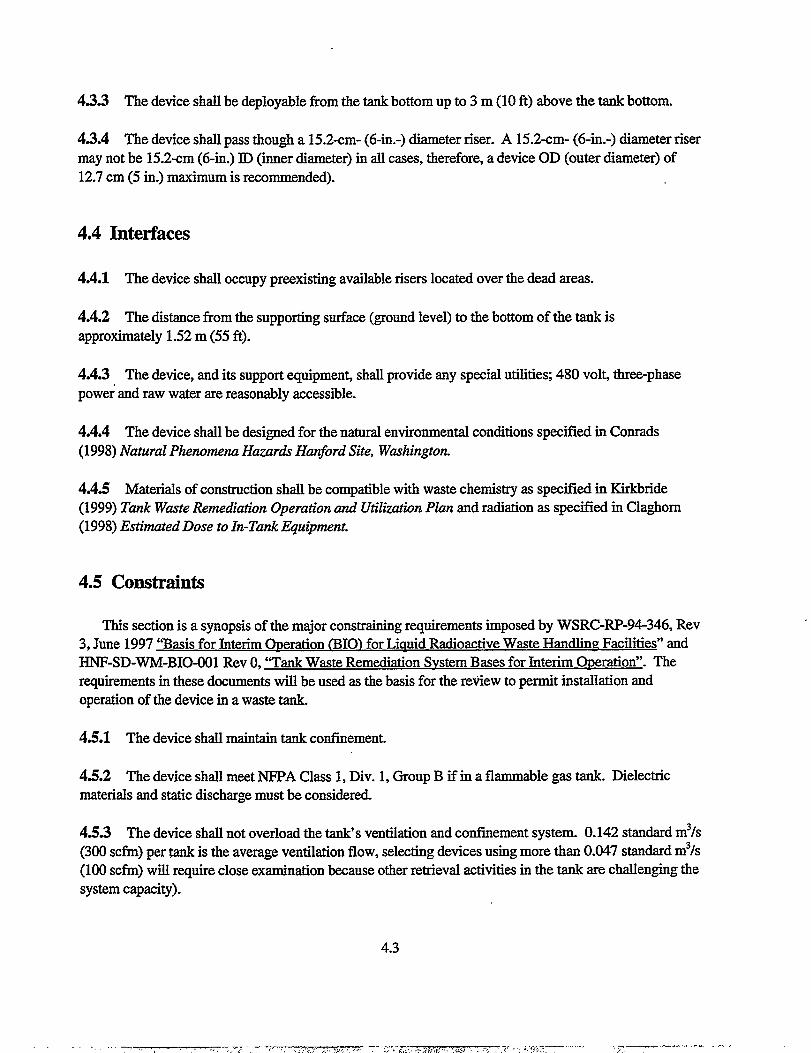
4S.3 The device shall be deployable from the tank bottom up to 3 m (10 ft) above the tank bottom.
43.4 The device shall pass though a 15.2-cm- (6-in.-) diameter riser. A 15.2-cm- (6-in.-) diameter risermay not be 15.2-cm (6-in.) ID (imer diameter) in all cases, therefore, a device OD (outer diameter) of12.7 cm (5 in.) maximum is recommended).
4.4 Interfaces
4.4.1 The device shall occupy preexisting available risers located over the dead areas.
4.4.2 The distance from the supporting surface (ground level) to the bottom of the tank isapproximately 1.52 m (55 ft).
4.4S The device, and its support equipmen~ shall provide any special utilitieq 480 vol~ three-phasepower and raw water are reasonably accessible.
4.4.4 The device shall be designed for the natural environmental conditions specified in Conrads(1998) Natural Phenomena Hazards Hanford Site, Washington.
&l.5 Materials of construction shall be compatible with waste chemistry as specified in Kirkbnde
(1999) Tank Wrote Rettwdiation Operation and Utilizatz”onPlan and radiation as specified in Claghom(1998) Estimated Dose to In-Tank E@@.n.ent.
4.5 constraints
This section is a synopsis of the major constraining requirements imposed by WSRC-RP-94-346, Rev3, June 1997 “Basis for Interim OPeration (1310)for Liauid Radioactive Waste Handling Facilities” andHNF-SD-WM-BIO-001 Rev O,“Tank Waste Remediation Svstem Bases for Interim Operation”. Therequirements in these documents will be used as the basis for the retiew to permit installation andoperation of the device in a waste tank.
4.5.1 The device shall maintain tank confinement.
4S2 The device shall meet NFPA Class 1, Div. 1, Group B if in a flammable gas tank. Dielectricmaterials and static discharge must be considered.
4.5.3 The device shall not overload the tank’s ventilation and confinement system. 0.142 standard m3/s(300 scfm) per @k is the average ventilation flow, selecting devices using more than 0.047 standard m3/s(100 scfin) will require close examination because other retrieval activities in the tank are challenging thesystem capacity).
4.3
,, ..-,,, ,,. .,, ; -; -.-;7, . ‘. .,.,,. ,, . ., ... .. . . . . -- ---- - -. . ~ , ., ;, -*-- --r -’,7—--————— “ ‘--”

4.5.4 The device shall not exceed heat input limits of the tank. For reference, the baseline mixer pumpsare two 224-kW (300-hp) uni~, 5 days of operating these pumps would raise the temperature of a 3785m3 (million-gal) tank to near the BIO (basis for interim operation) limit. Potential additional tank coolingneeds are being studied. As a target use 22.4 kW (30 hp) as an energy input limit for the proposed device.
4.5.5 The device shall not exceed dome-loading limits during installation, operation, or removal. Thisconstraint goes beyond the simple weight of the device and must consider dropping the device duringinstallation or removal and take into account any lateral loads the device may couple into the dome.Lateral loads may be either self inducd or induced by a mixer pump or earthquake. The device does nothave to remain operable during these loads, but must not damage the tank and must be removable afterthe loading event. For reference, mixer pumps weigh about 11340 kg (25,000 lbm)].
4S6 The device shall provide shielding for workers on the top of the tank.
4.5.7 Liquid addition, while allowable, is limited by space available and will be largely determined byprior partial retrieval.
4.6 Operational Needs
Operational needs include maintenance, ease of operation, removal and disposal. These requirementssimplify operation and are practical considemtions in the installation, operation, and removal of hardware.
4.6.1 Hardware features needing maintenance and calibration should be located remotely out ofradiation areas.
4.6.2 Rotating seals should be located in the riser or tzu& and a drain back to the tank shall be
provided.
4.6.3 If possible, active items needing maintenance should not be located in the waste or riser.
4.6.4 The device shall be internally flushable, free draining, with no crud traps, cracks, or crevices.
4.6.5 The device shall have guide fins to prevent snagging during insertion or removal.
4.6.6 The device’s internal voids, if not flushable or drainable, should be filled with foam.
4.6.7 The device’s wetted surfaces should be stainless steel with a surface finish 125 rms or better.
4.4

4.7 Assumptions
The requirements include the following additional assumptions.
4.’7.1 Radiation effects on materials understood by screeners. 1000 rads per hour is a conservativeassumption.
4.7.2 93.3 C (200 F) is the upp& bound of waste temperature.
4.7S Waste is caustic pI+b12.
4.’7.4 Soluble LLW tanks will not need sludge removal enhancement.
4.’7S The tank will have an operating camera system.
4.8 Updated Derived Requirements
The updated derived requirements listed in Table 4.1 encompass greater scope than those described inSections 4.1 through 4.7. References specific to these requirements are listed at the end of the table.
Table 4.1 Updated derived requirements for auxiliary solids mobilization
Function or Value/Specification Basis ReferenceRequirement Range
Process Specifications - Wrote Propertz”es
Effective 3 m to 6 m (9.8 ft to 19.8 The lower value represents atypical H-14-O1O5O7Sheet 1cleaning radius ft) distance from 10.2 cm (4 in.)/15.2 (6
Minimum performance in.) risers to the interior tankcriteria = 3 m sidewall. Available 1.1 m (42 in.)
risers are approximately 6 m fromthe sidewall.
Total Waste 579 KI (153 Kgal) to The range of reported total waste (HanIon 1999)volume (includes 4,232 KI (1118 Kgal) volume for the included tanks.saltcake andsupemate)Sludge shear 1.96 kPa (19,631 The lower value is commonly (Kirkbride 1999a),strength dynes/cm2, 41 lbfl~) to reported data from past AZ-102 (Shaw, 1999)
4.8 Wa (47,900 analyses. The higher valuedynes/cm2, 100 Ibflft’) represents the highest limit reportedMinimum performance in the Tank Waste Remediationcriteria =3.38 kPa (33,800 System Operation and Udlizationdynelcm’, 71 lbf/ft?) Plan.
4.5
. __ . _,. .. .-, ,e, ,....,..,~-..,...,.,., W-,.T 75?.,-... --- . -—-. ., ,. ,,. .—. —- -. .-..——

Function or Value/Specification Basis ReferenceRequirement Range
sludge volume 269 ICI(71Kgal) to 1196 The lower value is the repomd (Hanlon 1999)ICI(316 Kgal) volume in 214-SY-102. The higher
value is the reported volume forAW-103. The highest value alsorepresents the largest reported sludgevolume for the included tanks.While several of the noted tankshave no sludge, SY-102 data wasused for lower data because it was ahighlighted tank for auxiliarymixing. (Obviously Osludge wouldbe a the maximum low end, but notpractical for this scope.)
sludge bulk 1000 to 2000 kg/m3 (1 to 2 Core sample results of bottom sludgeiensity .gn.hnl) layers for AW-103 (#194) and SY-
102 (#213) (TWINS database)Sludge viscosity 0.06 to 10,000 N-s/m2 (0.6 Solids viscosity for AZ-101 and (Antoniak 1996)’, and
to 1.0 E+05 poise) other reported slurry viscosities (Kirkbnde 1999a)range from 0.05 to 0.1 N-s/m2 (0.5 to1.0 poise Other reported data forsolids are noted at 10 N-s/m2 (10,000cP). The referenced PNNL report isan internal letter report thatreferences other reporting da~,characterization data on sludgeviscosity is limited.
Weight percent 30-60% From AW-103 core sampling datasolids of in-tank extrapolated from reported percentsettled sludge water values (TWINS database core
194)Solids particle 0.2 to 50 ~ Commonly reported data for siudges (Kirkbride 1999a)size - typical smaller sizes, which tend to (Powell 1997)
be highly cohesive translates to highyield stresses in both shear andcompressive modes
Supematant Oto 329 Kl (Oto 87 Kgal) (Assuming a nominal ratio of 410 (Hanlon 1999)vohuneilevels Oto 7.4 m (293 in.) m3/m (2750 ga.lk.)
1 Antoniak, Z. I., K. P. Recknagle, Simulation of Tank 241-AZ-101 h40bili~.on Tests and TEMPEST
Code Pe~ormance Evaluation, Letter Report RET-093096, September 30, 1996, Pacific Northwest
National Laboratory, Richland, Washington.
4.6

Function or Value/Specification Basis ReferenceRequirement Range
Supernatant 1.0 to 1.2 Supematant grab sample resultsSpeCifiCgravity obtained from TWINS databaseWpematagt 0.0003 to 0.003 N-s/m2 Reported values from tank data and (Kirkbride 1999a)viscosity (0.3 to 3.0 CP) simulation runsWaste pH Caustic, 12 to +14 Commonly reported &@ waste
streams are a variety of sodium andother metallic salts
Radioactive dose Peak dose rate 1.0to 1100 Reported ranges (Claghom 1998)
Total Integrated Dose 3.6E05 to 9.5 E07 R
waste 15.5 to 35 C (60 to 95 F’) Reported ranges Surveillancetemperature for AW-103 & SY-102 Monitoring (TMACs)
15.5 to 87.8 C (60 to 190 for AW-103 and SY-F) for remaining tanks 102 and Temperature
profile data fromCharacterizationdatabase (Twins)
Operdionul Con&zmztion Boundaries
Discharge angle Adjustable angles in both Mixing may be adequate with a fixed Operation/design teamthe vertical and horizontal angle position directed at a single requestplane. Best operation dead zone or buildup area. Wastewould allow adjustment performance and shear strengths mayremotely without breaking require a variable angle to enhanceof confinement. mixing and impacting of thicker
sludges.Mixer height Variable (abiity to Mixing may be adequate with a fixed Operatiotidesign team
mob~ waste on bottom position unit set on tank floor request
and at increments 4.6 to directed at a single dead zone or6.1 m (15 to 20 ft) above buildup area. Waste properties,bottom tank elevation) specifically shear strengths, may
require a phased lowering of themixer to start movement of lowerdensity material before impacting onthicker sludges. Also, mixer mayneed to be elevated to mobilizesuspended solids in waste layers.
4.7

Function or Value./Specification Basis ReferenceRequirement Range
Instdhion Constraa”nts
Riser installationwidth for pumpand relatedassembly/mast
Utilities
availability
Naturalphenomena
design
Ventilationsystem impactsDeliveredhorizontaldisplacement onverticalprotuberances(e.g.,thermocoupleprobes) incleaning radiusMaterial ofconstruction
Available nominal riser
sizes: 10.2 cm, 15.2 cm,
30.5 cm, and 1.1 m (4 in.,
6 in., 12 in., and 42 in.)
240/480 VACFlush water through tankeror existing pipingNo instrument orcompressed airNone
<0.24 standard m3/s (50scfrn) additional loadMaximum 2.54 cm (1 in.)at tank bottom elevation
Wetted materials shall
maintain 5-year life
expectancy within waste
conditions; minimum 304
stainless steel on allwetted parts
Varied spare risers, and risers usedfor operations that could be
accessed (e.g., construction ports,
defunct installed equipmen~
camera ports etc.)
Current tank farm configurations;systems requiring compressed airor continual flushing will need toinstall auxiliary provisions
Final Safety Analysis
Report/Technical SafetyRequirements, however dependentupon final designConservative design estimate withexisti.ruzventilation svstemsCalculations for specific tanks andwaste protuberances will need tobe made on a case-by<ase basis.The reported range value isderived from calculation in AZ-101 but represents a conservativetarget for further evaluation
5 years estimated maximum lifefor staging tank application
H-2-64447 Rev 7H-14-O1O5O1Sheet 4Rev 2H-14-O1O5O2Sheet 2Rev 1H-14-O1O5O2Sheet 4Rev 1H-14-O1O5O7Sheet 1Rev OH-I4-O1O5O7Sheet 2Rev OH-14-O1O531Sheet 2Rev 2NIA
(LMHC 1999a)
Estimate
(Julyk 1997)
Estimate
4.8

Function orRequirement
Pit confinement
Safety Requireme~
Lift criteria
Electrical systemswithin tank vaporspace, and pits
Electrical SySteMSwithin submergedwaste streams
Weight
Control system
Value/SpecificationRanze
Installation on potentialrisers within pits shall notintrude upon piping, andshall allow forreinstallation of allexisting pit covers.
sInstallation/removal willbe per critical Mlrequirements of HanfordHoisting & R@@g .ManualMeets NFPA Class 1, Div1, Group B; design criteriashall be reviewed byindependent buyer expertgroupMeets NFPA chss 1, DIV
1, Group B or bedemonstrated by processthat submerged systemprovides no spruk to tankvauor since
Basis I Reference
Minimization of operational andproject impact
Final Safety AnalysisReport.fkchnical SafetyRequirement dome loading controls
Free supporting mast andpump assembly must meetallowable limits inaddition to mixer pumpsand retrieval pumps ORmay be designed to rest ontank bottom mysuppoti by floorCapable of beinginterlocked or remotelyshut down upon indicationof high waste temperatureor tank ventilationshutdown
4.9
Final Safety AnalysisReportfRdmical SafetyRequirement ignition controls
Final Safety AnalysisRepoflechnical SafetyRequirement ignition controls
Final Safety AnalysisReporuTechnical SafetyRequirement Dome LoadingControls value will need specificcalculation however generic rule isthat riser may support 45,359 kg (50ton) load limit
Final Safety AnalysisReport/Technical SafetyRequirement waste temperature andventilation controls
Operation costeffectiveness
(LMHC 1999a)AC 5.16
(LMHC 1999a)AC 5.10
(LMHC 1999a)AC 5.10
(LMHC 1999a)AC 5.16
(LMHC 1999a)LCOS 3.2.1,3.2.2,3.2.3,3.3.1, and 3.3.2
.... —- .-m-r-r--- , . ., ,, ,. . .. ., .-------.,7 .-4.>< 7-. - . . . . . .:-m=, .... .. > ... - ,./ =.,, , ,. .. ——. .. —. ..

Function orRequirement
Heat input
Value/SpecificationRange
Maximum sludge/wastetemperature rise of 5.6 C(10 1?)during continuousequipment operation andfollowing 12 hours
Basis
Final Safety AnalysisRepoMllAmical SafetyRequirement waste temperaturecontrols, estimated conservativevalue based upon safetyrequirements; target motor energyoutput should be in the range of 37to 75 kW (50 to 100 hp)
Reference
(LMHC 1999a)and engineeringestimation
Operation Maintenance, & Radiological Control Constraints
Localized control at tank I ALARA, and Conduct of operations \ NoneLocation of
control
mechanisms
Location of
electrical
componentsrequiringcalibrationRiser seal
Decontamination
Shielding
farm within tank farmcontrol room (greater than
100 m (328 ft) away from
tank)
Not Iotated within pits or
shielded areas
Shall maintain existingconfinemen~ riser seal
shall be gasketed.
Rotating seals shall be
liquid sealed with drain
back to the tank
Free draining, internal
flushable, with internal
void areas for material
trapping filled with
compatible solids (e.g.,
foam)
System shall be provide
with shielding for
protection of workers
during installation and
removal for disposal
ALARA and conduct of operationsallowing routine access forcalibration without removingshielding
ALAFM
Conduct of operations; currentplanning does not involve reuse ofmixer
ALAIL% current planning does notinvolve reuse of mixer
None
None
None
None
4.10
5. Evaluation of Enhanced Sludge Removal Technologies
Several studies have been conducted to provide background and a decision analysis for mobilizingand retieving sludge from double-shell tanks (Brothers et al. 1997, Powell et al. 1997). These studiesfocus on all of the double-shell tanks. Specific criteria are required to evaluate technologies for enhancedsludge removal.
Based on the selection guidance provided in Section 4, criteria for evaluation are developed inSection 5.1. These criteria are summarkd in tabular form in Section 5.2. In Section 5.3, the criteria areapplied to the technologies described in detail in Section 6.
5.1 Criteria for Evaluation
The selection guidance listed in Section 4.0 provides the framework to tailor a system for deploymentin a Hanford tank to assist in waste mobilization. Some of these criteria are essential qualities that adevice must possess to be considered for this application. Other criteria define parameters that could bemodified during construction to ensure that the device mates with the existing tank infrastructure. Othercriteria define qualities that can be added to an existing device to meet a speciiied function. The guidanceis prioritized to permit evaluation of existing commercial equipment for applicabtity for providing adevice to enhance sludge removal. In addition, changes noted in the Tede-schi(2000) that further definethese criteria are noted in bold.
5.1.1 Primary Requirements
Primary requirements are those that must be met by the device in order to perform the desired task.Three items were identified.
. The device shall assist waste mobhtion in dead areas.
. The device shall enhance mobilization for a radius of 3 m (10 ft) in waste with a shear strength of1.96 ld?a (41 lbf/@.
Note: Tedeschi (2000) defined the effective cleaning radius as 3 m to 6 m (9.8 to 19.8 ft) anddefined the minimum waste shear strength minimum performance criteria as 3.38 ld?a (71 lbf/ft2)
● To put the shear strength value in perspective, it is compared with sirmdants developed at Pacific
Northwest National Laboratory to m.o&l waste propem”es (Powell et al. 199Z Bamberger et al.
1998). A 50% kaoli~ 13%plaster, 37% water simulant developed to model sludge had a shear
strength of 2.5 kpa (52 lbf/j). A 22.5V0 kaoli~ 40% plaster, 37.5To water simulant developed to
model hard pan had a shear strength of 150 k%a (3133 lbf/f?). A saltcahz sirmdant (84To
dynamate in water) had a compressive strength of 19 MPa (396,825 lbf~). The shear strength
5.1

of 1.96 kPa (41 lb/f#)selected by Shaw and the m“ninnunpe~o rmaxe criteria shear strength of
3.38 kPa (7I lb@) defined in Tedeschi (2000) are both very low.
● The device shall pass through a 12.7- to 15.2-cm- (5-to 6-in.-) diameter riser.
Note: Tedeschi (2000) defined available nominal riser diameters of 10.2, 15.2,30.5 cm and 1.1
m (4,6, 12, and 42 in.)
5.1.2 Secondary Requirements
Secondary requirements include the ability to assess the condition of the waste in the tank. One item
was identified.
. The device shall detec~ locate, and measure accumulation of residual sludge.
4.3.2 The device shall locate waste accumulated in the dead area within ~ 0.3 m (1 ft) vertically.
Assessing the location of waste in the tank could be addressed by using the tank operating camera
system (identified as item 4.7.5) or by deploying specialized instrumentation as a part of, or in
conjunction with, the enhanced removal device.
5.1.3 Safety Requirements
The device operation must not compromise the integrity of the tank. All of the items listed in Section4.5 constraints fall into this category. Several of the items affect device operation and potentiallyperformance.
4.5.2
4.5.3
4.5.4
4.5.5
4.5.7
The device shall meet NFPA Class 1, Div 1, Group B if in a flammable gas tank. Dielectricmaterials and static discharge must be considered.The device shall not overload the tank’s ventilation and confinement system. [0.142 standardm3/s (300 scfm) per tank is the average ventilation flow, selecting devices using more than0.047 standard m3/s (100 sciin) will require close examination because other retrievalactivities in tie tank are challenging the system capacity].Note: Tedeschi (2000) defines the ventilation system impact as <0.023 standard m3/s (50scfm) additional load.The device shall not exceed heat input limits of the tank. As a target, use 22.4 kW (30 hp) asan energy input limit for the proposed device.)Note: Tedeschi (2000) defines the heat input as a maximum sludge/waste temperature rise of5.6 C (10 F) during continuous equipment operation and following 12 hours.The device shall not exceed dome loading limits during installation, operation, or removal.[For reference, mixer pumps weigh about 11,340 kg (25,000 Ibm).]Liquid addition, while allowable, is limited by space available and will be largely determinedby prior partial retrieval.
5.2

5.1.4 Design - Construction - Installation Details
Many of the operational needs and materials of construction can be addressed after selection of thetype of enhanced retrieval system during its design and construction for deployment in a specific tankriser or series of tank risers.
5.2 Evaluation Matrix
Based on the information presented above, two tables were constructed to permit compaison of thetechnologies. In Table 5.1, the sludge mobilization technologies are compared. In Table 5.2, thetechnologies are compared against the ranking criteria.
5.3 Technology Evaluation
The technologies described in Sections 6 and 7 have enough information regarding operation duringtesting for radioactive deployment or actual operation in a radioactive waste environmen~ therefore, theywere selected for comparison to the deployment selection criteria. In Table 5.3, the technologies arecompared with respect to the ability to mobilize sludge. Jn Table 5.4, the technologies are grouped intothree categories: 1) meeting the ranking criteria 2) the ability to be modified to meet the ranking Criteri%and 3) not readily modified to meet the ranking criteria.
5.4 Technology Summary
Based on the acceptance criteri% one technology, the borehole-miner extendible-nozzle has theproven ability to meet key primary requirements. The borehole-miner extendible-nozzle can mobilizeextremely hard waste at a distance of 3 m (10 ft). The arm extension of 3 m (10 ft), and its abfity tomove back and forth, can be used to sweep waste from collection piles deposited by the mixer pump backinto the mixer pump path or toward the retrieval pump inlet. The current device mast is larger than the15.2-cm- (6-in.-) diameter rise~ however, this dimension could be modified for the application.
Two other technologies, the pulsating mixer pump and fluidic pulse-jet mixing will fit through a 15.2-cm- (6-in.-) diameter riseq however, the technologies need to be evaluated to determine the effectivecleaning radius of the technology and the range of shear strengths of sludge that they can dislodge.
5.3
—— —.--, ---- -.-, - .- ,--,7-- ----- . ..— ,. . . . ,.. , . . . ,. .:. . .-. W..-, ~ ,—— -—-.. .

Table 5.1 Matrix for technology comparison
CriteriaTechnique
IIJet mt-ssure
Mixes slurriesMobilizes settled solidsDislodges solid heels
Power
Adds heat to tank during
Percent secondary waste
generatedDeployment
Rerno&ly deployed
Maintainability .Removal
Teebnology IType of mobilization system
Provides jet pressure range and fluid
Fluid flow rate per jet
Technology specificTechnology specific
Technology SpeCifiC
Technology SpeCifiC
Technology S@fiCPower required to produce jet
Technology SpeCtiC
Is system operation limited by the waste level in the tank or other
constraints?Based on the amount of water the system adds to the tank
How is the system deployed?
Yes or no.
What pm need periodic maintenance and where are they located?
How is the system removed from the tank?
5.4

Table 5.2 Criteria for technology selection
Number and Criteria Technology MeetsThe Criteria
4.2.1 Assist wastemobilization in dead areas
4.3.1 Enhance mobilizationfor a radius of 3 m (10 ft)
4.3.1 Enhance mobilizationof 1.96 kPa (41 Ibflfl?) sheustrength sludge4.3.4 Pass through 15.2-cm-(6-in.-) diameter riser
4.2.2 Detec4 locate and I
measure accumulation ofresidual sludge
4.3.2 Locate wasteaccumulated in a dead areawithin *0.3 m (1 R)vertically4.5.2 Meets NFPA Ckzss 1,Div 1, Group B forflammable gas tank I4.5.3 Does not overloadtanks ventilation orconfinement system[generates <0.047 standardm3/s (100 scfm) aerosol]4.5.4 Does not exceed tankheat input [22.4 kW (30 hp)]4.5.5 Does not exceed domeloading limits [<11340 kg(25,000 lbm)]4.5.7 Limited Iiauid addition
Technology Can BeModified To MeetCriteria
5.5
Technology CannotReadily Be ModifiedTo Meet Criteria

Table 5,3 Comparison of the waste mobilization technologies
Criteria Pulsed Air Pulsating Fluidic C-106 Borehole- Waste- High- Flygt Mixer MixerMixer Pump Pulse-Jet Sluicer Miner Retrieval Pressure Pump
Mixing Extendible- End Effecter SearifierNozzle
Technique compressed compressed compressed water or fluid water or fluid water jet water jet propeller high-volumeair pulses air propels air propels jet jet creates a fluid oscillatory
slurry jet slurry jet jet fluid jets
Jet 0.35 to 0.69 0 to 0.69 0 to 0.69 to 2,07 MPa Oto 20,7 0 to 69 or 207 379 MPa up to 2.8pressure MPa (5 to MPa (Oto MPa (Oto (300 psi) MPa (Oto MPa (Oto (55,000 MPa (400
100 psi) air 100 psi) 100 psi) 3000 psi) 10,000 or psi) psi )liquid30,000 psi)
Flow rate 0.005 tbd tbd 0.022 m3/s o to 0.0095 0.0063 m~ls 0.00038 1.1 m3/s up to 0.315standard (350 gallmin) m31s (0 to (10 gal/rein) m3/s (6 (17,500 m3/s (5000m3/s (10 150 gal/rein) /jet gal/rein) gallmin) gal/rein) /jetscfm) air /jetper plate
Enhances tbd yes yes yes yes yes yes yes yesdissolution
Mixes yes yes yes yes yes yes yes yes yesviscousliquids
Mixes yes yes yes yes yes yes yes yes yesslurries
Mobilizes to some to some to some to some yes yes yes to some extent yessettled extent extent extent extentsolids
Dislodges no no no perhaps yes yes yes no if close tosolid heels mixer pumpPower 7.5 to 15 tbd tbd 186 kW (250 149 kW (200 tbd tbd 37 kW (50 hp) 224 kW (300
kW(lOto hp) hp) hp)20 hp)
5.6

PulsatingMixer Pump
insignificantrWaste- High-
Retrieval PressureEnd Effecter Scarifier
Criteria
Addsheatto tankduringoueration
Pulsed Air
insignificant
FluidicPulse-JetMixing
insignificant
C-106Sluicer
BorehoIe-Miner
Extendible.Nozzle
yes
functionsatall liquidlevels
o%
riserarm
F1ygtMixer MixerPump
yes some yes yes yes
-1.2 m(4ft)headrequired formaximumpower.Nozzlecenterline-0,3 to 0.46m(l to 1.5ft) ffom tankbottom
functions whensubmerged.
Operatinglimits
functions at functions atall liquidlevels, nozzlelocated <15,2cm (6 in.)from floor
o%
riser mast
functions atall liquidlevels,nozzlelocated<15,2 cm (6in,) fromfloor
o%
functions atall liquidlevels
o%
riser mast
all liquidlevels,plateslocated<2.54 cm (in,) abovethe tankfloor
I levels I Mixer is 51 cm
o% 0.00038
(20 in.) indiameter andwas installed20.5 cm (8 in.)above tankfloor,Minimum fluiddepth is51 cm(20 in,)
o%Percentsecondarywastegenerated
Deploy-ment
0% >0% (someseallubricationwater added)
m3/s (6gallmin)
T/jet
arm or remote arm orvehicle remote
vehicle
riser mast,systemunfolds
riser mast riser mast,system unfolds
riser mast,systemremainsunder riseryesyesRemotely
deployedyes yes yes yes yes
5.7
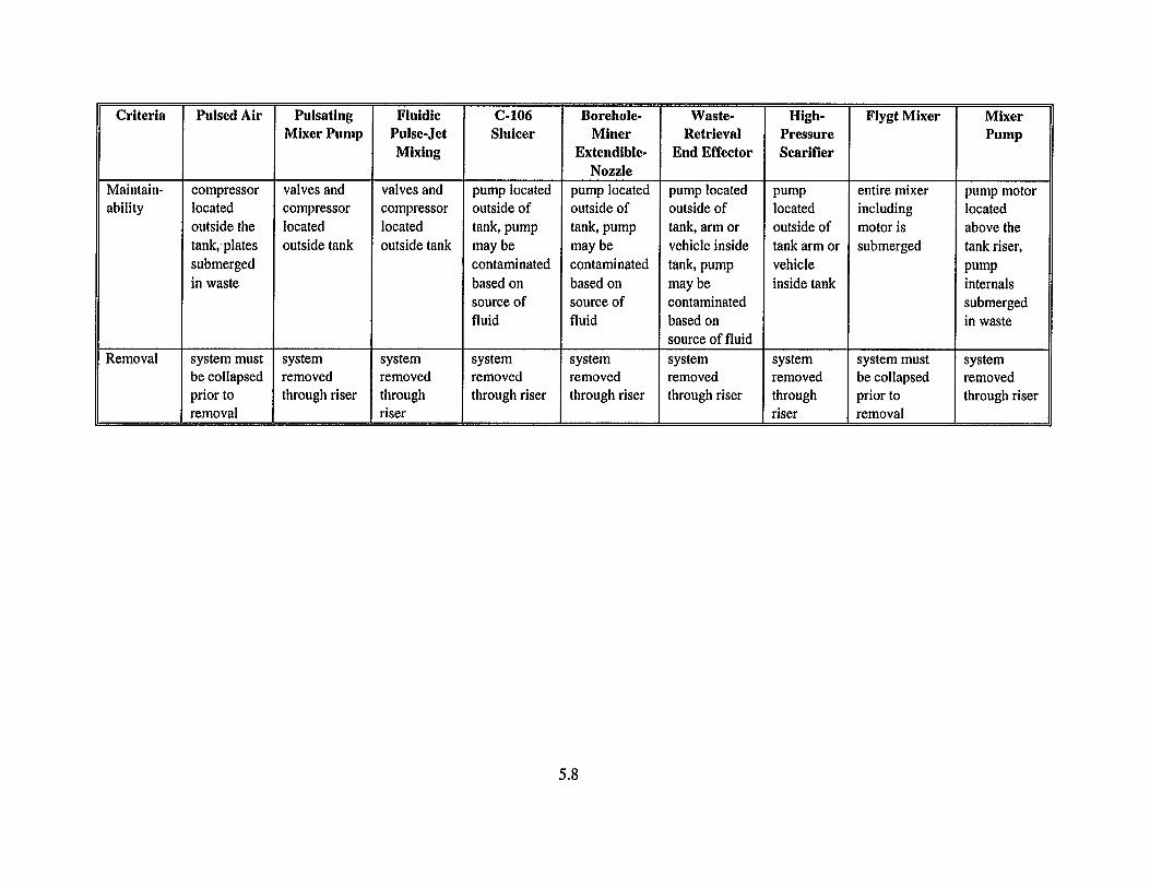
Criteria
Maintain-abilityy
Removal
Pulsed Air PulsatingMixer Pump
submerged Iin waste
system must systembe collapsed removedprior to through riserremoval
Fluidic C-106Pulse-Jet SluicerMixing
contaminatedbased onsource offluid
system systemremoved removedthrough through riserriser
Borehole-Miner
Extendible-Nozzle
pump locatedoutsideoftank,pumpmay becontaminatedbased onsource offluid
systemremovedthrough riser
Waste- High-Retrieval Pressure
End Effecter Scarifier
pump located pumpoutside of locatedtank, arm or outside ofvehicle inside tank arm ortank, pump vehiclemay be inside tankcontaminatedbased onsource of fluid
system systemremoved removedthrough riser through
riser
Flygt Mixer
entire mixerincludingmotor issubmerged
system mustbe collapsedprior toremoval
MixerPump
pump motorlocatedabove thetank riser,pumpinternalssubmergedin waste
systemremovedthrough riser
5.8

,:,,...:!“. .,,,
. .-,
.,+, ~
;,.!
Table 5.4 Comparison of the enhanced removal technologies with the acceptance criteria.
Number and Criteria Technology Meets The Technology Can Be Modified Technology Cannot Readily Be Modified To MeetCriteria To Meet Criteria Criteria
4,2.1Assist waste Pulsed Airmobilization in dead Pulsating Mixer Pump
areas Fluidic Pulse-Jet MixingC-106 SluicerBorehole-Miner Extendible-NozzleWaste-Retrieval End EffecterHigh-Pressure ScarifierFlygt Mixer
4.3.1 Enhance C-106 Sluicer Pulsed Air
mobilization for a radius Borehole-Miner Extendible-Nozzle Pulsating Mixer Pump
of3m(10ft) Fluidic Pulse-Jet MixingWaste-Retrieval End EffecterHigh-Pressure Scarifier
4,3.1 Enhance C-106 Sluicer Pulsed Air
mobilization of 1.96 kPa Borehole-Miner Extendible-Nozzle Pulsating Mixer Pump
(41 lbf/ft2) shear Waste-RetrievalEnd Effecter FluidicPulse-JetMixing
strengthsludge High-PressureScarifier Flygt MixerThejet pe~ormance must be evaluated to determine whethermobilization of this shear strength sludge could occur at aradius of 3 m (lOft)
4.3,4 Pass through 15.2- Fluidic Pulse-Jet Mixing Pulsed Air Waste-Retrieval End Effecter
cm- (6-in.-) diameter C-106 Sluicer Pulsating Mixer Pump High-Pressure Scarifier
riser Borehole-Miner Extendible-Nozzle Flygt MixerThe design of these devices and their deployment systemwould need to be radically modified tojit through a 15.2-cm-(6-in.-) diameter riser
5.9

Number and Criteria Technology Meets The Technology Can Be Modified Technology Cannot Readily Be Modified To ICriteria To Meet Criteria Criteria
4.2,2 Detect, locate and Pulsed Air
measure accumulation of Pulsating Mixer Pump
residual sludge Fluidic Pulse-Jet MixingC-106 SluicerBorehole-Miner Extendible-NozzleWaste-Retrieval End EffecterHigh-Pressure ScarifierFlygt MixerNone oj the technologies are equipped with sensors o~pe
4.3.2 Locate waste Pulsed Air
accumulated in a dead Pulsating Mixer Pump
area within ~ 0.3 m (1 ft) Fluidic Pulse-Jet Mixing
vertically C-106 SluicerBorehole-Miner Extendible-NozzleWaste-Retrieval End EffecterHigh-Pressure ScarifierFlygt MixerNone of the technologies are equipped with sensors qtype,
4.5.2 Meets NFPA Class Pulsed Air Waste-Retrieval End Effecter Flygt Mixer
1, Div 1, Group B for Pulsating Mixer Pump High-Pressure Scarifier The system motor is located inside the tank.
flammable gas tank Fluidic Pulse-Jet MixingC-106 SluicerBorehole-Miner Extendible-Nozzle
4,5.3 Does not overload High-Pressure Scarifier Pulsed Air
tanks ventilation or Pulsating Mixer Pump
confinement system Fluidic Pulse-Jet Mixing
[generates <0.047 C-106 Sluicer
standard m3/s (100 scfm) Borehole-Miner Extendible-Nozzle
aerosol] Waste-Retrieval End EffecterFlygt Mixer
5.10

Number and Criteria Technology Meets The Technology Can Be Modified Technology Cannot Readily Be Modified To MeetCriteria To Meet Criteria Criteria
4.5.4 Does not exceed Pulsed Ak Flygt Mixertank heat input [22,4 kW Pulsating Mixer Pump(30 hp)] Fluidic Pulse-Jet Mixing
C-106 SluicerBorehole-Miner Extendible-NozzleWaste-Retrieval End EffecterHigh-Pressure Scarifier
4,5,5 Does not exceed Pulsed Airdome-loading limits Pulsating Mixer Pump[<1 1,340 kg (25,000 Fluidic Pulse-Jet Mixinglbm)] C-106 Sluicer
Borehole-Miner Extendible-NozzleWaste-Retrieval End EffecterHigh-Pressure ScaritierFlygt Mixer
4,5.7 Limited liquid Pulsed Air Waste-Retrieval End Effecter High-Pressure Scarifieraddition Pulsating Mixer Pump The 379 A4Pa(55,000 psi) intensiflerpuntps operate with
Fluidic Pulse-Jet Mixing jlltered water,C-106 SIuicerBorehole-Miner Extendible-NozzleFlygt Mixer
5.11

6.Deployed Technologies for Enhanced Sludge Removal
A series of technologies to mobilize, mix, and retrieve waste have been deployed at US Departmentof Energy sites. Many of these technologies were developed as a pat of the Tanks Focus Area RetrievalProcess Development and Enhancements projectl (Rinker et al. 1996,1997, Bamberger and Rinker 1996).Some of these technologies maybe applicable for enhanced sludge removal at Hanford. Because theyhave been deployed at radioactive whte sites, these technologies maybe more mature with respect toissues specific to deployment at Hanford therefore, they are grouped together and discussed in thissection. Each of the technologies is assessed to determine whether”the technology can meet two criteria1) be configured for installation in a 15.2-cm- (6-in.-) diameter riser and 2) mobilize sludge with a shearstrength of 1.96 ld?a (41 lbf/ft2).
6.1 F1uidic Pulse Jet Mixing
Fluidic pulse-jet mixing utilizes pulse-jet agitation to mix sludge with liquid supematant. The systemmixes the sludge and supematant via a three-phase mixing process: a suction phase, a drive phase, and avent phase, shown in Figure 6.1. This approach has been deployed at Oak Ridge National Laboratory tomobilize and retrieve waste from five horizontal storage tanks (W21, W22, W23, Cl, and C2) (Murrayand Peters 1999, Kent et al. 1998& b).
utC)unol?Vms
----- . . . .. . . . . .. . .
sumla
,,,+.,”,,”W<,,N,,,.+.,,,,,,,.:* ,,, ~,.,, ,..,.,j.,s,.,,..,. y,,&’,,.,.. .~,.,., . ....*$4 ,,,;:>?,,, .e~,...... .>..... &
: .. . .. . ./ .;.. .,.;+. ..-;it’: :.;;,,y~.> +. ... ... ... . ..-<. .,. “w’ :’7-”:
,,$,q~’+s//.:.:.-: >,-., :.., ...’ :.. :x
\(A) SUCTION PHASE ‘
\(B) DRIVE PHASE ~
Figure 6.1 Pulse jet operating phases
\(C) VENT PHASE
\
1 Rinker, MW, JA Barnberger, FF Erian, TA Eyre, BK Hatchell, OD Mullen, MR Powell, TJ Samuel,GA Whyatt, and JA Yount. 1998 EA4-50Tanks Focus Area Retrieval Process Development and
Enhancements FY98 Technology Development Summary Repoti, PNNL-12015 Drafg Pacific Northwest
National Laboratory, Richland, Washington.
6.1
.-—- . ‘71 Te-lm--.m --.-, -..,.--, .- r, . /-... ,, ./,.. ...... ..?7.. s : -<...-.7 . ,.$?...,,.-,... -v,. ,,. ., .. -:- ?----- ,, ,, ----- - -- ~

6.1.1 Pulse-Jet Mixer Operating Cycle
During the suction phase, the jet pumps create a partial vacuum in the charge vessel, which in turn
draws liquid up from the waste tank into the vessel. Once the charge vessel has been filled with
supematant, the jet pump pressurizes the charge vessel, which drives the supematant back into the tank;
this flow agitates the contents of the tank and resuspend settled solids into the supematant. This is the
drive phase. When the supematant levels have reached the bottom of the charge vessels, the drive phase
is terminated and the charge vessel is depressunzed through the jet pump in the vent phase. The cycle is
then repeated until the sludge and the supematant have been mixed.
6.1.2 Pulse-Jet Mixer System Components
The pulse-jet mixer system is modular. It consists of the charge vessel assembly, piping manifold, jet
pump skid, valve skid, off-gas skid, and control system-
6.1.2.1 Charge Vessel Assembly
The charge vessel assembly includes the charge vessel (with a sludge nozzle at its base), a rotating
mechanism to move the nozzle position, and a support assembly that houses the rotating mechanism. The
stainless steel charge vessel operates at pressures from vacuum to 0.69 MPa (100 psi). The nozzle at the
base is configured to meet the needs of the application. One application used a 3.8-cm-(1 .5-in.-) diameter
forward facing nozzle and a 1.O-cm-(0.375-in.-) diameter rear-facing nozzle attached to a 7.62-cm-(3-in.-)
diameter pipe. The purpose of the smaller nozzle was to clear sludge away from the tank wall; the
purpose of the larger nozzle was to mobilize the majority of sludge toward the center of the tank.
6.1.2.2 Jet Pump Skid
The air line piping that connects the jet pump to the charge vessel extends vertically upward to
barometrically protect the jet pumps so that no sludge would be able to reach the jet pumps during the
suction operation. For a recent application the piping extended 10.4 m (34 ft) above the top of the tank
being mobilized. A charge vessel requires two jet pumps, a drive jet pump and a suction jet pump as
shown in Figure 6.2. The diffuser end of each drive pump is connected to the charge vessel. The diffuser
end of each suction pump is connected to the off-gas system. The inlets to both of the paired pumps are
connected to the compressed air supply via the piping manifold and valve skid.
6.1.2.3 Off-Gas Skid
During the vent phase of the pulse-jet mixing system, gas is vented from the charge vessels via jet
pumps. The off-gas will have been in contact with contaminated supematant in the charge vessel;
therefore, a protective off-gas system is required. The off-gas first passes through a demiste~ the
6.2

demister drain line could be routed back into the tank. At ORNL the off-gas intermittent flow rate rangedfrom Oto 0.40 m3/s [0 to 850 cfin (Oto 4000 I/s)], sufficient capacity to operate two charge vesselssimultaneously.
[: ,TO CHARGE
NOZZLE DRIVE JET PUMP DIFFUSERVESSEL
(a) JET PUMP PAIR
fijuc.*oNl)f_(M OPERATING MODES
Figure 6.2 Jet pump configuration and operation
6.1.3 Pulse-Jet Mixer Performance
The theological properties of the ORNL sludge were evaluated. The maximum shear strengthobserved was 20 Pa (0.42 lbflf?), 100 times less than that anticipated in the Hanford high level waste.Tests using china clay with a shear strength of 16 Pa (0.33 lbf/f?) as a waste simukmt were alsoconducted at ORNL.
Kent (et al. 1998%b) reports that the pulse-jet mixer skids were installed at ORNL over a period of 7weeks. The system was operated remotely for 52 days; during that period 88~0 of existing sludge wasremoved from a 189-m3(50,000-gal) horizontal tank. 242 m3 (64,000 gal) of liquid was required totransfer 23.6 m3 (6300 gal) of sludge. 8870 of the liquid used was existing or recycled tank supematant.Only 29.4 m3 (7770 gal) of process water was added to the system. Kent also reports that a simplemanual sluicer was used periodically to wash down and aid the removal of localized sludge heels.
Murray and Peters (1999) reported that the campaign to retrieve waste from Tanks C-1 and C-2 wasto be initiated in early 1999. Dahl et al. (1999) described the results from these transfers. Tank C-2 wasemptied first. A total of 30.7 m3 (8100 gal) of sludge, 99%, was transfemti to Tank W-23. After the
6.3

charge vessels were moved from Tank C-2 to Tank C-1, approximately 11.7m3(3100 gal) of sludge
(95%) were transferred from Tank C-1 to Tank W-23. Total waste removed from Tank W-23, as a result
of this and an eadier campaign, was 71.1 m3 (18,775 gal), almost 99%.
6.1.4 Pulse-Jet Mixer Deployment for Enhanced Sludge Retrieval
The pulse-jet mixer piping can be configured to fit through a 15.2-cm- (6-in.-) diameter riser. The
charge vessel assembly would need to be located above the tank.
The pulse-jet mixer data indicates that the system was ordy used to resuspend slurries with very low
shear strengths. Testing would be required to determine the effective cleaning radius for slurries and
sludges with shear strengths of 1.96 kPa (41 lbf/ft2).
6.2 Borehole-Miner Extendible-Nozzle Sluicer
The borehole-miner extendible-nozzle .sIuicer, shown in Figure 6.3, uses a semi-flexible, extendible,erectable arm to direct a high-pressure sluicer jet. The arm extension and position are controlled remotelyfrom a control console. This system was deployed at Oak Ridge National Laboratory to dislodge andremediate four horizontal underground radioactive waste tanks in 1998 (F3ambergeret al. 1998, 1999~ b).
6.2.1 Extendible-Nozzle Operation
The extendible nozzle uses supematant to form a low-flow-rate, high-pressure fluid jet. The nozzlediameter ranges from 0.51 to 1.02 cm (0.2 to 0.4 in.)”diameter, operating pressures range from linepressure up to 20.7 Ml?a (3000 psi), and flow rates range from 0.0032 to 0.0095 m3/s (50 to 150 galhnin).The jet range is up to 15.2 m (50 ft) stand-off distance, and the arm can extend up to 3 m (10 ft),providing a potential reach of 18.3 m (60 ft). Using supematant as the jet fluid limits water addition tosystem flushing activities at the end of daily operation. Specifications for the system deployed at OakRidge are listed in Table 6.1.
6.2.2 Extendible-Nozzle System Components
The extendible-nozzle system includes the mast pump, piping, and ventilation system.
6.4

L--—--—--— _____ J
Figure 6.3 Extendible nozzle deployment and conilgmationLegend: 1) top mast assembly, 2) platform assembly, 3) lower mast assembly, 4) arm assembly,
5) launch assembly, 6) control console, 7) bridge moun~ and 8) containment hose assembly
6.2.2.1 Mast
The mast houses the extendible-nozzle arm. The arm consists of small metallic links that are heldtogether with tensioning cables. The arm links mesh together by cylindrically shaped bearings andbearing sockets (pivot points). The 20.7 MPa (3000 psi) water hose runs through the center of the armlinks. The arm is extended and retracted into the mast by a hydraulic motor-driven chain and tie rodsystem. While tensioned, the arm can be deployed radially to a distance of 3 m (10 ft) from the mastcenterline, and also from a horizontal position to vertically downward. In addition, the mast and nozzleassembly can be rotated M 80 degree to give complete coverage of the tank. Movement and tensioning ofthe arm are accomplished hydraulically, and the arm’sposition and extension are determined bypotentiometer-type encoders.
A double-conduit coaxial hose is used to feed the high-pressure water to the inside of the upper mast.The outer shell is constructed from a 6.2-MPa (900-psi) working pressure, 24.8-MPa (3600-psi) burstpressure hose. In the event of a hose burst, the maximum pressure in the shell is estimated to be less than0.69 MPa (100 psi).
6.5
I

Table 6.1 Extendible-nozzle speciilcations
Description I Speci13cation
Maximum slurry line working pressure 20.7 MPa (3000 psi)
Design flow rate I 0.0095 m3/s (150 gpm )
Maximum arm extension 3 m (10 ft) from mast centerline
Arm range of motion
Rotation & 180 degree
Azimuth 90 degree (horizontal to vertically downward)
Platform vertical range 76 cm (30 in.)
Weight 2835 kg (6250 lbm)
Maximum arm extension rate 25.4 Cm/S (10 ill./S)
Minimum launch angle rate 9 degreels
Mast rotation speed 0.012 to 1.2 rpm
Maximum arm rinse working pressure 1.0 MPa (150 psi)
Maximum spray ring working pressure 1.7 MPa (250 psi)
Exposed materials. Materials exposed to waste are stainless steel (300 series, 15 to 5 pH), hard
chromium plate, nickel plate, polyurethane enamel-coated carbon steel, polyurethane, neoprene,
polyethylene, nylon.
The extendible-arm assembly has four mechanical motions: mm tensioning, angle positioning, arm
extension, and mast rotation. Each of these four motions is accomplished with a single independent
hydraulic manifold. Each manifold is supplied with a joystick-operated, manual, flow-control valve. The
four joy sticks are the interface between the operator and the motion. During sluicing, the position of the
extendible nozzle was controlled manually using the control console. A lifting shackle to carry the
weight of the mast and mast mount assemblies is located at the top end of the mast. A fulcrum is located
as the bottom of the mast so that the mast can be pinned to a support structure and put in a lay down
position.
The mast length is designed for each application and is based on the height of the tank. When
deployed at ORNL the extendible nozzle was designed for dimensions of 4.5 m (14.9) ft from grade to
tank bottom and 2.4 m (8 ft) dlamete~ the mast was approximately 8.8 m (29 ft) in length and was made
up of two sections with a bolted flange joint. A design, for deployment at Savannah River Site Tank 19
with dimensions of 13.7 m (45.1 fi) from grade to tank bottom tank and 13.0 m (42.5 ft) high; required
mast length extensions to permit deployment in a deeper tank. The Savannah River site design is very
similar to that required for deplo yment at Hanford. Hanford 3875 m3 (million-gal) tanks are
approximately 16.8 m (55 ft) from grade to tank bottom with a tank height of 14.6 m (48 il) while 2006
m3 (530,000 gal) tanks are approximately 11.3 m (37 ft) from grade to tank bottom with a tank height of
9.5 m (31.25 ft).
The mast support mount consists of a bridge mount assembly that is bolted to a portable platform
over the tank riser and supports the mast assembly at the desired elevation over the tank floor. To ensure
6.6

that no radioactivity will escape through the mas~ the npst mount assembly includes a bellows-typeexpanding containment cover, shown in Figure 6.3, which encloses the portion of the mast that.will beexposed to tank waste. A clamp-on cover plate is used to close the end of the containment cover duringstorage. A second bellows cover is located between the bridge mount and riser flange. An interfaceflange is located at the bottom of the cover to attach to the riser. During transfem from tank-to-ti thebottom of the second bellows is sealed to enclose the extendible-nozzle components.
6.2.2.2 Sluicer Pump Skid
The sluicer pump skid includes the high-pressure pump, variable-speed drive, valves, andinstrumentation to control and monitor the pump pressure.
6.2.23 Pumping System
The primary components of the pumping system are:
Low-pressure transfer pump to transfer contents from the sluicing tank to the mixing tankMixer in mixing tank to maximize slurry mixing
Low-pressure feed pump [1.4 MPa (200 psi) progressive cavity Moyno pump] to lift contents fromthe mixing tank and feed to the high-pressure pump
Strainer to remove larger particles from the feed to the nozzleProcess water system used to flush the lines after transfer and provide other process water needs at thesiteAssociated piping and valves including tank &op legs and riser modifications
Containment piping, riser confinement boxes and confinement skid enclosures.
6.2.2.4 Ventilation System
The primary components of the ventilation system are:● High-efficiency particulate air (HEPA) filter system on the air intake to minimize treatment HEI?A
loading and minimize discharges to atmosphere in the event of a ventilation system shutdown
● Demister to remove water vapor from the air stream
. Heater to reduce the relative humidity of the air stream● Primary and secondary HEPA system to filter air discharged from the ventilation system● Single-speed fan to drive the airflow
. Discharge stack and associated stack monitoring.
6.2.3 ORNL Conf@m@on Extendible-Notie Weight
The bridge mount and stand are estimated to weigh 1361 kg (3600 lbm). The combined weight of themast and bridge mount is estimated to be -2880 kg (6350 Ibm), distributed over an area 2.4 m x 2.4 m (8
6.7

ft x 8 ft) on the surface. The maximum force load that is transferred to the supporting surface (ground) asa result of the jet thrust moment is -481 kg (1060 lbm) (at maximum jet thrust with the moment loadtaken on one leg of the stand). The mast weight is estimated to be -1247 kg (2750 Ibm). Lifting shacklesto carry the weight of the bridge mount during installation and removal are incorporated in the bridgemount structure.
6.2.4 Extendible-Nozzle Operating Experience and Performance
The borehole miner extendible nozzle was deployed at Oak Ridge National Laboratory to mobilizeand mix 159 m3(42,000 gal) of low level waste stored in five horizontrd underground storage tanks. Thetanks contained 45.7 cm (18 in.) of sludge covered by supemate. In 1998, over a period of less than 3weeks, the borehole-miner extendible-nozzle system was deployed to remediate these tanks.
Prior to deployment at ORNL, tests were conducted at Pacific Northwest National Laboratory to
characterize the performance of the borehole-miner extendible-nozzle. The tests were conducted using
sludge waste simulants with shear strengths ranging from 2 to 150 kPa (42 to 3133 lbf7ft2) and salt cake
simulants with compressive strengths up to 19 NIPa (396,825 lbf/ft2). The nozzle stand-off distances
evaluated ranged from 1.5 to 15 m (5 to 50 ft). The borehole-miner extendible-nozzle was able to
dislodge and mobilize simukmts with this broad range of physical and theological properties.
The extendible-nozzle system at ON was designed to penetrate through a 30.5-cm (12-in.) riser.
The masL hose, and extension mechanism could be reconfigured to be deployed through a 15.2-cm- (6-
in.-) diameter riser. A configuration for extended sludge resuspension would probably not require an
operating pressure of 20.7 MPa (3000 psi) or be able to operate at a stand-off distance of 18.3 m (60 ft);
therefore, the system size could be reduced for this application.
6.2.5 Extendible-Nozide Deployment for Enhanced Sludge Removal
The extendible-nozzle can be configured to fit through a 15.2-cm- (6-in.) diameter riser. The nozzlelength of extension would be con.tlgured so that the unit could be deployed to reach specified areas todk.lodge and mobilize waste with the nozzle water jet.
The extendible-nozzle performance data indicate that the system is well suited for dislodging andmoving waste with physical properties that are much more challenging than the specified shear strengthof 1.96 ld?a (41 lbf/@. Testing would be required to determine the effective cleaning radius for slurriesand sludges with shear strengths of 1.96 kPa (41 lbf/ft2); it is expected that the ECR would be on the order
of the extendible nozzle range of 15.2 to 18.3 m (50 to 60 ft) stand-off distance.
6.8

63 C-106 Sluicer
Hanford Projwt W-320 installed the waste retrieval sluicing system (WRSS) in Tank 106-C tomobilize high-heat generating sludge in Tank 106-C to transfer it to Tank 102-AY. The tank wasclassified as a high heat watch list tank with a heat load estimated to be 34.6 kW (118,000 Btu/hr),generated in a sludge layer about 1.8 m (6 ft) thick. The supematant liquid layer above the sludge was 1.9m (77 in.) deep, varying over the range from 1.92 to 1.99 m (75.6 to 78.4 in.) due to evaporation and theaddition of cooling water every 20 to 30 days. These additions were typically on the order of 7.6 to 11.4m3 (2000 to 3000 gal) and raised the tank liquid level by approximately 2.54 cm (1 in.). Evaporationwould subsequently lower the liquid level at a steady rate until the next addition. The process flow shee~shown in Figure 6.4, defines system components, operating pressures and flow rates; the sluicer detailsare shown in Figure 6.5 (Carothers et al. 1999).
6S.1 Sluicer Sys@m Components
The sluicer is constructed of 304L stainless steel and has a 2.54-cm- (l-in.-) diameter nozzle with twodegrees of motion control (rotation 194 degrees) and nozzle elevation (130 degrees). The nozzlepivotdrotates at a fixed elevation in the tank and can be aimed with a dedicated hydraulic system. Thesluicer controls can be operated in manual or semi-automatic mode.
The sluicer pump system is a tandem pump that includes an adjustable heigh~ submersible slurrypump in the tank and a variable-speed slurry booster pump in the pit above @lay 1996). The submersibleslurry pump is a centrifugal, direct-drive, end suction, 30-kW (40-hp) immersible pump with a 0.6-cm-(0.25-in.-) mesh intake screen. The submersible pump pumps waste from the tank to the 186-kW (250-hpvertical direct-drive, variable-sp~ centrifugal slurry booster pump. The sluicer is approximately 29.2cm (11.5 in.) in diameter and is installed in a 30.5 (12-in.)-diameter riser.
6.9
—-y-- .,—.- -‘—-. ,. .,-..--T-. .<.. . . . . . . . ..--$ n :- -A,,-.. . . .. . u ,, .. , .--?Z-. -.,-: r..-.?- .:- -?n,n--— ------

@
o
00
J .:
t: -o- +—iKJ3— II11-
Figure 6.4 Tank 106-C process flow sheet
6.10

-.
,“
31!tD -
h
+ 1“
%—-
‘/”i/“”-..— ... ..—..—..——- ....—- - .. ... .. . .. . .... ... . -—. ....... —/
“j;,’.,-
,.
““li

6.3.2 Sluicer Operation
The sluice nozzle orientation is hydraulically controlled. The nozzle swings through a 130 degreevertical arc, from horizontal to-40 deg. On the horizontal axis, the sluicer can sweep in a 194 deg arc.The sluicer can operate in a fixed position, sweep in an automatic mode, or be controlled by the joy stock.Maximum operating pressure is 2.07 MPa (300 psi). The nominal sluicer flow rate is 0.022 m3/s [350galhnin (140 fth)]; the minimum flow rate to keep solids in suspension is 0.019 m3/s [300 galhn.in (120fth)]. The system safety limit is 0.041 m3/s [650 galhin (270 fds)]. Nozzle horizontal and verticalposition is indicated on the sluicer controller. The sluice stream can also be monitored on the videomonitor in the control trailer. The sluicer was used to mobilize the waste in phases. The proposedoperation is shown in Figure 6.6. The actual operations are surnmruized in Table 6.2.1
1.1.1 3.1.13.1.2
B“
1-a5dsm 74!
3.21
M
M
3.23
Ud
CAMPAIGN1 CANPAtGN2 CAMPAIGN3
Not6aal: X.Y-Z
X.campdgny-lncmrnmt
Figure 6.6 Planned sluicer operation
6.3.3 Sluicer Performance
The sluicer has been successfully operated between November 1998 and October 1999 to sluice wastein Tank C-106. No information regarding the waste rheology is available. This lack of informationsuggests that the shear strength is not a significant issue. The liquid density is -1.2 g/cm3 (74.92 lbrn/ft3),the sludge bulk density is 1.6 g/cm3 (99.89 Ibrnhl?), and the waste particulate density is 2.6 g/cm3(162.3lbrn/f+).
] Cum J.M., K.G. Carothers, D.W. Darnschen, J.A. Lechelt, B.E. Wells, K. %t.hyanarayan% and L.A.
Stauffer. 1999. Review of Waste Retrieval Sluicing System Oper~.ons and Tank Data for 24I-C-106
and 241-AY-102. Draft. Pacific Northwest National Laboratory, Richland, Washington.
6.12

Table 6.2 History of T&dc 106-C sluicing transfers
Date Heat had Sludge Net Heat Net Sludge cam- Plan- ActualTransferred Volume Load Transferr4 paign ned Dur-in Batch Transferred Phase Dnr- ation
ationkW BWhr m gal kW Btu/hr Kl gal da da
11/18/98 0.199 680 29.56 7810 0.199 680 29.56 7810 1.1.1 12 2812/16/98 0.144 491 8.744 2310 0.343 1171 38.31 10120 Process 81
TesLPhase 1
317199 0.804 2746 88.2723320 1.147 3918 126.6 33440 Process 21TesLPhase 2
3/28199 2.211 7548 158.941965 3.359 11465 285.4 75405 Process 26
TesLPhase 3
Total for 3.359 11465 2%4 75405 88 156CampaignIll4/23/99 0.0969 331 6.98 1843 3.455 11797 292.4 77248 2.1.1 5 5
4/28199and 0.927 3166 55.2814603 4.968 16963 347.7 91851 2.1.2 14 264/30/995124199 0.0536 1830 25.30 6683 4.918 16793 373.0 98534 2:2.1 5 10
6/3/99 2.641 9017 107.328353 0.075825809 480.3 126887 2.2.2 14 48
Total for 4201 14344 194.951482 38 89Campaign#27/21/99and 0.0155 5208 50.5913365 9.084 31017 530.9 140252 3.1.1 5 14
7122199 (part 1)814199 0.132 450 4.37 1155 9.216 31467 535.3 141407 3.1.2 14 16
8/20/99 0.535 1826 20.19 5335 9.751 33293 555.5 146742 3.1.3 21
9/10/99 0.977 3337 33.73 8910 10.73 36630 589.2 155652 3.2.1 5 4
9/14/99 0.534 1823 18.43 4868 11.26 38453 607.6 160520 3.2.2 5 2
9/16/99 1.121 3828 44.5511770 12.38 42281 690.0 172290 3.2.3 14 5
9/21/99 0.477 1628 18.95 5005 12.86 43908 671.1 177295 3.2.4 3
9!24/99 0.339 1159 13.85 3658 13.20 45068 685.0 180952 3.2.5 2
9126199 0.232 793 9.47 2503 13.43 45861 694.4 183455 3.2.6 2
9/28/99 0.102 349 4.16 1100 13.53 46210 698.6 184555 3.2.7 2
9/30199 0.120 410 4.89 1293 13.65 46619 703.5 185847 3.2.8 6
10/06/99 0.357 122 1.46 385 13.69 46741 704.9 186232 3.2.9Total for 6.13 2Q932 224.659345 43 77
Campaign#3 “Total for 13.69 46741 704.9entire 186232sluicingoperation
6.13
— ,..—.— _,, ..,.,..“. ,..-.~e . . . . ., . . -- T.m . . ..-

6.3.4 SIuicer Deployment for Enhanced Sludge Removal
The sluicer current design is for insertion through a riser with a diameter much larger than 15.2 cm (6in.) It is expected that the sluicer may be redesigned to be installed through a 15.2-cm- (6-in.) diameterriser. Some loss of performance may occur.
6.4 Pulsed-Air Mixer
In 1999, Oak Ridge NationaJ Laboratory deployed a pulsed-air mixer in Tank W-9 to mix wastesolids and accelerate settling of >100-pm-diameter particles. Puke air technology was identified in 1994as a potential method to enhance mixing in underground storage tanks. The technology was developedfor deployment at ORNL at Pacific Northwest National Laboratory as a part of the Retrieval ProcessDevelopment and Enhancements project.
6.4.1 PuLsed-Air Mixer Operation
The pulsed-air mixing technique utilizes short, discrete pulses of air or inert gas to produce largebubbles near the tank floor. The bubbles are produced beneath horizontal circular plates positioned justabove the tank floor. These bubbles rise toward the liquid surface and induce mixing, as shown in Figure6.7. The pulse frequency, duration, gas pressure, and plate sequencing are controlled to create a well-mixed condition within the tank. Pulsed-air mixing differs from conventional air sparging; in pulsed-airmixing single, large bubbles are introduced into the tank fluid periodically (once every 15 s); in sparging,small bubbles are injected continuously. The rapid expansion of the pulsed-air bubbles near the tank floorand their subsequent rise through the fluid serve to both lift solids from the tank floor and maintain thosesolids in a uniform suspension.
The system deployed at ORNL Tank W-9 utilized a dual-plate pulsed-air mixe~ shown in Figure 6.8.
In this design air pulses can be applied either to the underside of the bottom plate or between the plates.
Pulsing air under the bottom plate clears away sludge and allows the mixer to penetrate through piles of
sludge. Once the mixer reaches the floor, air pulses are applied only between the plates. This eliminates
the tendency of the plates to lift with each pulse.
1 Andrews, R.M. PITVF Pzdsair T& Wate Fluidizing, September 19 & 20, 1994, Hanford,Washington. P&air Systems, Inc., Bellevue, Washington.
Powell, M.R. and G.A. Whyatt. 1999. ORNL Tank W-9 Pulsed-Air Mixer Desig~ D@ensibility and
Peflo nnance Evaluation. PNNL-1 1918 Drafg Pacific Northwest National Laboratory, Ricldand,Washington.
Powell, M.R, M.A. Sprecher, C.R. Hymas, D. Winkel, R.M. Andrews, and R.E. Park. 1995. I l\12-Scale Testing of a Pulsair Mixing Array: An Evaluation of Pulsed-Bubble Mixing for Hanford Waste
Retrieval and Processing Applications. March, PacKlc Northwest Laboratory, Richlan& Washington.Pulsair Systems, Inc. Pulsair Pneumatic Batch Mixing. 1993. Pulsair Systems, Inc., Bellevue,
Washington.
6.14

,.. ., ......, .,,,. :.. ‘r, “./,. ,,~.
.*.; - J& :-?.&::.:.:,—,,’ .,.
..,. . :, .,,.. .. . . . . .. .
Figure 6.7 Pulsed-airbubble formation,growth, and coalescence. Courtesyof R&air Systems,IIIC.
6.4.2 Pulsed-Air Mixer System Components
The pulsed-airmixer system includes an arrayof horizontal, circularplates positioned just above thetank floor. Pipes connected to each plate supply pulses of compressedgas to the underside of each platevia special commercially available gas pulsing valves.
Compressed Air
II
J ~‘ ~~
36-cm Diometer
[Accumulator Plates
0.64 cm $
k- Tank F!oor
Figure 6.8 Dual-platepulsed-air mixer configuration
6.4.2.1 Mixer
The ORNL TanlcW-9 mixer consists of 13 circuku accumulator plates positioned to cover the tankfloor. Each plate is 27.9cm(11 in.) in diameter and is connected to a 2.54-cm (l-in.) schedule 40 pipe.Each pipe is connected to a compressed air pulsing valve outside of the tank. The mixer plate diameterwas selected to fit through the 83.8-cm- (33-in.) diameter tank risers.
6.15
... .. . - -,r.. J,. x..--.-7,-m7 . . . . . . . . , . . ., m ,~y.-r .7.-,. , --..V,>:-,7 , ,-.—,- . . .–- - I
6.4.22 Deployment System
To reach positions other than beneath the tank riser, au inverted umbrella deployment system wasdesigned and evaluated. The selfdeploying assembly is lowered through the tank riser. When it contactsthe tank floor, it unfolds like an inverted umbrella. This concept is shown in F@re 6.9.
6.4.23 Pulsed-air Controller and Valves
The mixer controller, gas pulsing valves, and compressed air supply are located outside the tank. Thecontroller permits independent adjustment of pulse rate, plate sequence, and pulse duration. The gaspressure can be adjusted between Oand 0.69 MPa gauge (Oand 100 psig) using a pressure regulatorlocated upstream of the 0.30-m3 (80-gal) compressed air storage tank. The 0.30-m3 (80-gal) tank providesenough compressed air to pulse 13 plates simultaneously. This valve controls operating pressure andprevents migration of radioactive materials into the compressed air supply. A Oto 0.069 Ml?a gauge (Oto10 psig) pressure regulator on the downstream side of the compressed air tank provides a slow flow ofcompressed air to each accumulator plate. This pressure keeps waste from entering the pipe and ensuresthat any waste-bearing aerosols inside the pipes are prevented from migrating up the air pipes to the air-pulsing valves.
6.4.2.4 Containment and Contamination Control
During normal mixer operation there are two potential pathways for loss of waste containment:aerosol generation from mixing action within the tank and migration of waste-bearing aerosols up thecompressed air pipes against the flow of compressed air. The maximum aerosol loading expected toresult from pulsed-air mixing is estimated to be 50 mg (O. 11 lbm) of wet aerosol per of cubic meter of gassupplied to the mixer.1 This estimate is based on aerosol production rates measured in a variety ofexperiments.
1 Powell, M.R.and G.A. Whyatt. 1999. ORNL Tmk W-9 Pulsed-Air Mixer Desigw Defensibility andPerjormanc e Evaluation. PNNL-1 1918 Dra& Pacific Northwest National Laboratory, llichlan~
Washington.
6.16

.;.:
.,x :,s ii. !!
I II
;:
Figure 6.9 Multiple mixer plates deployed via the inverted umbrellaapproach
6.17
.-r. . -% . .; ..?..,7,=,Z5FF2 .. .. .. .. ..- ,7-T-.-, .,X -, . . . . ,.., . . . . . . . . . . . . . . . . .. LJ,. . . . . . . c.. - :.::.:., .-,j~ -- ——--— ---

6.4.3
In
Pulsed-Air Mixer Operating Experience and Performance
1999, a pulsed-air mixer arrayinstalled in ORNL TamkW-9 was operatedto mix the tankcontents.Upon resuspension, the slurry was recirculated through a slurry monitoring test system to evaluate the
slurry transport properties. The pulsed-air system was installcxl as three separate assemblies with a total
of 13 accumulator plates.
Four pulsed-air system parameters were evaluated during the demonstration: dwell time, the time
between air injections (10, 14, 18 s); injection time, the amount of time air is injected through a pulse
plate (1 s); air supply pressure [0.24 MPa (35 psig)]; and recirculation pump elevation from the tank floor
[1.2 to 1.8 m (4 and 6 ft)]. Test results show that the mixing time was dependent upon dwell time. The
shorter dwell time mixed the tank more quickly. Also the equilibrium condition obtained in the tank was
dependent upon the elevation of the retrieval pump. The highest concentration, 3.1 wt% solids, was
obtained when the recirculation pump was positioned 1.2 m (4 ft) from the tank bottom.
6.4.4 Pdsed-Air Mixer Deployment for Enhanced Sludge Removal
The pulsed-air mixer plate diameter selected for deployment at ORNL was 27.9cm(11 in.). The
plate area must be reduced by a factor of 3.4 to provide a system that could be deployed through a 15.2-
cm- (6-in.) diameter riser.
In addition, the system only has been tested with kaolin clay slurries, not with sludges with
measurable shem strengths. If the deployment issue is addressed, tests with a waste sirnulant with a shear
strength in the range of the required 1.96 kPa (41 lbf/ft2) must be evaluated to determine the extent of
resuspension.
6.5 Waste-Retrieval End Effecter
k 1997,ORNLselected a lightweight scarifying end effecter, a jet-pump conveyance system andtwo deployment systems: the light duty utility arm (LDUA) and the Houdini remotely operated vehicle(ROV) to perform the Gunite and associated tanks treatability study (GWT-TS). Two scarifier endeffecters were evaluatd the sludge retrieval end effecter (SREE) optimized for sludge retrieval and thegunite scarifying end effeetor (GSEE) optimized for scarification of gunite surfaces. These are bothvariations of the confined-sluicing end effecter (CSEE). Diagrams of the sludge retrieval end effecter andthe gunite scarifying end effecter are shown in Figures 6.10 and 6.11.
6.18

ION
HANDLE BRACKET
GRIPPER HANDLES
– ~// CONV=.CEPORT
‘L MOTOR CANISTER
MAN CHASSIS
7NANIFOLO ASSEMBLY
az!;com.
Figure 6.10 Sludge retrievalend effecter
PI——————45’:”””u
35 KSI MANIFOLD
GUARD RING
SMALLsTANDoFF
L&W NOZZLE
STANDOFF HUB
Figure 6.11 Gunite scarifying end effecter
6.19
.— --— ...- .,.. . --- .7 —.. -.,=. . ———..

63.1 Waste Retrieval End-effecter Operation
Scarifying end effecters employ a rotating array of small water jets to fragment and dislodge waste.The jet nozzles are rwrayedon a manifold which rotates about an axis normal to the waste surface. Thejet size and pressure, rotational frequency, and traverse speed are tailored to the properties of the waste.The end effecter was approximately 38.lcm (15 in.) in diameter and was deployed through a 53.3-cm-(21-in.-) diameter riser. The sludge retrieval end effecter operated at pressures from 2.07 to 69 MPa (300to 10,000 psi), and the gunite scarifying end effecter operated at pressures from 2.07 to 207 MPa (300 to30,000 psi). The flow rate per jet was variable up to 0.0063 m3/s (10 galhnin).
6S2 Waste-RetrievaI End-EHector System Components
The end-effecter system includes the end effecter, the deployment mechanism – either a remote
vehicle or an arm-based deployment system the pump to supply pressurized water to the end effecter and
the conveyance system.
63.3 Waste-Retrieval End-Effecter Performance
The sludge retrieval end effecter was deployed in ORNL Gunite Tank W-3. The waste depth wasestimated to be 0.6 m (2 ft) after the supematant was removed. The waste was stratified in irregularlayers; some appeared to be fairly solid or elastic, like damp chalk or gypsum, other layers were moreviscous. A rough estimate of sludge properties was made based on video tape records. The larger piecesof sludge appeared similar in strength to a bentonite-water slurry in the 15 to 20 wt% solids range. Theshear strength of such a mixture is between 0.1 and 1.5 kl?a (2.1 to 31 lbf/#).
To remove waste from Tank W-3, operators held the SREE 0.3 to 0.6 m (1 to 2 ft) away from the
surface and operated the SREE at 6.9 to 27.6 MPa (1000 to 4000 psi) at 200 rpm to slurry the waste.
Then they lowered the SREE into the slurry with jets and rotation still on to pump it out with the
conveyance pump.
Severe mixing and occlusion of visibility occur while scarifying with the SREE because theconveyance system doesn’t move enough air to capture ejects and spray for the jets scattered by theirregular concrete surface and there is no shroud to cordine the spray to the immediate area.
During clean out of Tank W-3, the SREE used 21.4 m3(5658 gal) of water to dislodge 41.7 m3(11,014 gal) of waste. An additional 53.2 m3(14,063 gal) of water was used by the jet pump conveyancesystem. Additional information is provided in Rule et al. (1998).
6.20

6.5.4 Waste-Retrieval End-Effecter Deployment for Enhanced Sludge Removal
The waste-retrieval end effecter has the ability to dislodge sludge and waste with high shearstrengths, so it is well suited to dislodge the waste piles. However, the system would require a completeredesign to engineer a system to be deployed through a 15.2-cm- (6-in.-) diameter riser. Also, significantancillary equipment to deploy the end effecter either via remote vehicle or arm-based deployment isrequired.
6.6 PulsatingMixer Pump
In 1999, pulsating mixer technology, consisting of ajet mixer powered by a reciprocatingair supply,was selected for deployment in Oak Ridge National LaboratoryTank TH-4 to mobilize settled solids.The pulsating mixer technology was identified as a promisingtechnology that could be implemented inthe DOE complex, duringFY 1996 andFY 1997 technical exchanges between the US DepartmentofEnergy Tanks Focus Area Retrieval and Closure pro- the DOE Environmental ManagementInternational Programs, and delegates from Russia. The pulsating mixer technology, provided by theRussian Integrated Mining Chemical Company, was tested at Pacific Northwest National Laboratory toobserve its ability to suspend settled solids. Based on the results of this demonstration, ORNL and DOEstaff determined that a modified pulsating mixer would meet project needs for bulk mobilization of ~itetank sludge prior to deployment of other retrieval systems. This deployment is expected to save the costsassociated with operation and maintenance of more expensive retrieval systems.
6.6.1 Pulsating Mixer Pump Components and Operation
The original pulsating mixer pump, shown in Figure 6.12, consists of an upright cylindrical reservoir,a foot check valve, a working-gas supply pipe, a discharge manifold and jet nozzles. The gas supply pipeis plumbed to a control valve, which alternates the exposure of the line between a vacuum and air supplysource. Ih operation, the waste is drawn into the reservoir through the foot check valve when the supplypipe is valved to the vacuum source. The supply pipe is then pressurized with supply aiq the pressurizedair discharges the fluid out of the monitor reservoir back into the tank through the jet nozzles.
6.6.1.1 Pulsating Mixer Pump Evaluation at PNNL
Only two jet nozzles were used during testing at PNIWXhowever, there are four ports for jets in thehead. The preliminary drawings showed a fifth nozzle directed axially downward on the centerline of themonitor, but the port for that jet was not present on the test article.
The vacuum supply to the pulsating equipment was provided by an axial-jet eductor furnished withthe equipment. A diesel-powered trailer compressor supplied compressed air to the pulsating monitor andthe vacuum eductor. The eductor was supplied and specified by.Integrated Mining Chemical Company asrequiring 4 m3/rnin (141 cfrn) of air delivered at approximately 0.48 MPa gauge (70 psig) to produce 0.40
6.21

Ml?agauge (5.8 psig) of vacuum. The air supply line to the eductor was operated at a pressure of 725 I&agauge (105 psig) and was throttled to obtain the desired vacuum line pressure. The actual airflow rate tothe eductor was not measured-
TANK F
FLUID
Figure 6.12 Pulsatingmonitorsystem tested at PNNL
At PNNL, the operation of the pulsating mixer pump was demonstrated in a 5.7-m- (18.75-ft-)diameter tank. The pulsating mixer pump operation was visualized using medium grain sand [1 to 2.4mm (0.004 to 0.1 in.)] spread over the tank bottom and water as a supematant liquid. The size of the sandwas selected to be large enough so that the pulsating mixer pump jets would not suspend the sand when
6.22

the system was operating at the control settings selected for the demonstration. The purpose of the sandwas to provide flow visualization of the influence that the pulsating mixer pump jets have on the test tankfloor. The pulsating mixer pump contained two diarnetically oppos~ 8-mm- (0.31 -in.-) diameternozzles. Two tests, Tests 3 and 4, were conducted with the pulsating mixer pump remaining stationary(not rotating).
Test 3 was conducted with the nozzles oriented in a north-south direction. During Test 3, the.period
was 21s, and the vacuum and supply pressures were 77 I&a absolute (11.1 psia) and 557 kPa gauge (80.7
psig), res~tively. The pulsating mixer pump was run for 9 min.; then the cleared area on the tank floorwas measured. The dimensions for the observed area of jet influence on the bottom of the tank arepresented in Figure 6.13. The pulsating mixer pump was not located in the center of the tank.
The first jet pulse cleared the floor of sand out to a distance of approximately 1.5 m (5 ft) and on thesecond pulse to about 1.8 m (6 ft). After the first four pulses, the growth of the footprint slowedconsiderably. After 9 min. of operation, the jets were still moving sand on the bottom of the tank causingthe cleared area to grow at a slow rate.
For Test 4, the pulsating mixer pump was rotated 90 deg to orient one of the nozzles to erode a thicklayer of sand. The pulse rate was maintained at 21s, tmd the time average pressures were 78 kPa absolute(11.4 psia) and 556 kPa gauge (80.7 psig) for the vacuum and supply pressure, respectively. Test 4 wasrun for approximately 4 min. The dimensions for the cleared area created by the jet to the west of thepulsating mixer pump (i.e., through the thick layer of sand) are presented in Figure 6.13.
6.6.1.2 Control System Planned for Use at ORNL
The primary functions of the control system are 1) to permit the pulsating mixer pump system tooperate optimally over a range of operating conditions; 2) to provide automatic shutdown in case an out-of-spdfication condition occu~, and 3) to allow remote operation of the system from either the inside ofthe ORNL Gunite Tank Farm control sh~ which has a maximum distance horn the tank risers of 91 m(300 ft), for the riser site. Under steady-state operating conditions, the pulsating rnixerpump shouldrequire minimal manual intervention. However, if changes do occur in the operating conditions (e.g.,changes in the height of the tank fluid in the concentration of the tank slurry, or fouling of the checkvalves or nozzles), adjustments must be made to rebalance the system. If the changes area continualoccurrence, continual or periodic action will be required.” The system operation relies on the fill andevacuation phases of the pump cycle being balanced with regards to the flow rate. What is drawn into thereservoir must be discharged. If the system is out of balance, the volume of fluid in the reservoir willeither incrementally decrease, eventually resulting in the discharging of air to the@& or incrementallyincrease, resulting in fluid being drawn into the vacuum line.
The instrumentation will include sensors to measure liquid level in the pump chamber, chamberpressure, supply air pressure, and flush water pressure to allow the system to be remotely monitored Theprocess data will be display@ on a graphical user interface and allow the operator to view time-cyclicdata. The control system will allow the operation to open ~d close valves individually; configure valvesfor standard and back-flush operations; adjust mixer rotational spe@ and adjust intake and exhaust
6.23
---- ----- ------ .-.-,... ..—. —- —-- ........-——--— --.;2$-4- ~

duration, pump pressure, and slurry exhaust rate. Data will be monitored by the control program to
recognize indications of system degradation, such as an increase in cycle time.
Tank Dmmeter= 5.72 m (18.75fI) .,
\t I .“1
Test 3 Results
Dimension m in. Dimension m in.A 2.34 92 F 1.6to 1.7 63 to 66B 0.79 to .81 31-32 G 0.20 8c 1.57 to 1.60 62-63 H 0.25 10D 2.59 102 I 0.08 3E 0.76 to 0.79 30-31 J 0.08 3
Test 4 ResultsDiiension m in. Dimension m in.A 2.51 99 H 0.08 3B 0.60 24 G 0.08 3c 1.78 to 70 to 72
1.83
Figure 6.13 Diagramand dimensions of jet footprint created by pulsating mixer on tank floor.
6.24

7. Demonstrated Technologies for Enhanced Sludge Removal
The applicability of many technologies has been evaluated for deployment at Hanford or other USDepartment of Energy sites. To provide some consistency between tests, many investigators usedstandardized simulant recipes for wet sludge, hardpan sludge, and saltcake wastes. Powell (1996) andPowell et al. (1997) describe the sirnulant recipes and physical and theological characterization. Thetechnologies that have been evaluated using specified simulants are described in this section. Thesetechnologies may not be as mature as the technologies described in Section 6 that have already beendeployed for radioactive waste remedktion.
Several of these technologies were evaluated through the Hanford Tanks Initiative project. Thepurpose of this project was to evaluate commercial technologies for potential deployment for wasteremediation.
7.1 High-Pressure Sca*er
A high-pressure scarifier rated to remove 0.0009 m3/s (2 ft3/min) of waste was initially developed forretrieval of hard single-shell tank salt cake waste (Bamberger et al. 1993~ b and 1994) with no signiilcantaccumulation of fluid within the tank. This system used high pressure [379 MPa (55,000 psi)] jets and airconveyance to dislodge and retrieve waste. The system performed well; however, Hanford Sitedeployment needs changed and a lightweight version of the scarifier, shown in Figure 7.1, was designedand tested.
&’”
/ f?.
&Jnmm
-IdkuqIJ-msPn-)
Figure 7.1 Lightweight scarifier deployed by light duty utility armdislodging salt-cake simulant7.1

The lightweight scariiler uses two ultra-high-pressure water jets to fracture and dislodge waste. The
waterjets require 0.00038 m3/s (6 galh-nin) of water at up to 345 MPa (50,000 psi). The jet manifolds
rotates between O and 1000 rpm. The motor that controls rotation is mounted concentric to and inside the
annular conveyance inlet shroud. The scarifier weighs approximately 22.7 kg (50 lbm), is 25.4 cm (10
in.) diameter, and 48.3 (19 in.) high (Hatchell 1997).
The lightweight scariller was deployed with the EMMA robotic manipulator to evaluate the system’s
ability to dislodge salt cake and dried sludge waste simulants (Grey Pilgrim 1997).
7.2 Advanced Sluicing System
Los Alamos Technical Associates, Inc. (1997) tested sluicer nozzle performance. Two nozzle
configurations were evaluated to determine their ability to erode salt cake and hard pan waste simulants.
The nozzles tested had bores of 2.54 and 3.175 cm (1 and 1.25 in.). The nozzles were tested at stand-off
distances of -5.2 m (-17 ft). Against the hardest salt cake waste simulant [20.7 MPa (432005 lbf/ft2)
compressive strength] sluicing was able to dislodge waste at rates greater than 1.4 X10⁴ m3/s (0.29
ft3/min). For hard pan simulant [32 kPa (662 lbf/ft2)] removal rates were 3.9 X10⁴ m3/s (0.82 ft3/min)]
using the 3.175 cm (1 .25 in.) nozzle, and for another hard pan simulant [150kPa(3139 lbf/ft2)] removal
rates were 1.2 x10⁻⁵ m3/s (0.025 ft3/min) using the 2.54-cm (1-in.) nozzle.
7.3 Vehicle Deployed Sluicer
Ard Environmental (1996, 1997a, b) tested a self-propelled robotic crawler vehicle that deployed
various tools including a rotating cutter, scabbler, and hydraulic jack hammer to evaluate the ability of the
combination to dislodge wet sludge, saltcake, and dried hardpan waste simulants.
The hydraulically driven vehicle, shown in Figure 7.2, weighed 907 kg (2000 lbm) and provided 6508
N-m (4800 ft-lbf) of torque. The sluicer was equipped with 14 sluicing nozzles with a diameter of 0.128in. and a Odeg spray angle. The operating flow rate was 0.0072 to 0.0077 m3/s (114 to 122 gaknin) at2.8 to 3.1 MPa (400 to 450 psi). The sluicer eductor, located in the center of the sluicing nozzles, had asuction capacity of 0.0063 m3/s (100 galhin).
7.2

I——~ L
.%
1 . .M.LhwsmmmmlNINcHEs
Figure 7.2 Vehicle with sluicer attachment
7.4 Flygt Mixers
Axial shrouded-propeller mixers developed by ITT Flygt Corporation are being evaluated fordeployment in Savannah River Site Tank 19 to resuspend sludge, zeolite, and salt that remain in the tankafter a retrieval campaign conducted in the early 1980s (_Powellet al. 1999% b, c). During this campaigntwo jet mixer pumps were used to dissolve and retrieve the salt cake. This technology may also beapplicable for deployment at Hanford.
Flygt mixers consist of an electrically-powered propeller surrounded by a close-fitting shroud.
Specially sized mixers were designed for deployment in Tank 19. These 37-kW (50 hp) mixers being
considered for use in Tank 19 have a propeller diameter of 51 cm (20 in.) and operate at 860 rpm. The
spinning propeller creates a turbulent fluid jet with an average exit velocity of 5.4 m/s (17.7 Ws). The
mixers are shown in Figure 7.3. The mixers were rnodiiied to include a wire-mesh screen to protect the
propeller from in-tank debris. With the inlet screen installed and the mixer operating at full speed, the
mixer is expected to generate a water flow rate of about 1.1 m3/s (17,500 galh.in). This flow rate
corresponds to a mixer thrust of 6160 N (1385 lbf) and a hydraulic power of 30 kW (40 hp). Four mixers
were procured for eventual installation in Tank 19.
A series of scaled tests were conducted to evaluate the Flygt mixers. Key findings show that fluidvelocities in the 30 to 50 crnhi (0.98 to 1.6 fds) range are required to maintain 20x50-mesh zeoliteparticles suspended in water. For all particles to remain in suspension, the average fluid velocity 5 cm (2in,) above the tank floor must exceed 50 ends (1.6 ftk) in all locations. Measurements to date made atfull scale confii scaled predictions that three fixed position Model 4680 Flygt mixers do not provide
1Trumbull, Connecticut.7.3
- . .—--- —— - -,7.--.X. -., , ,,..7,7.- . . . . ,,. . .. ...—--. .—.

sufficient mixing intensity to achieve the required fluid velocities near the tank floor in all regions of thetank to keep zeolite in suspension.
No data for the shear strength of the Tank 19 heel were available. Scaled Flygt mixer tests in a 0.45-m-(1 .5-ft-) diameter tank were conducted using kaolin clay in water with a shear strength of 0.4 kl?a (8.4lbf/ft2). Recommendations have been made to test the full-scale mixers in the 5.7-m- (18.75-ft-) diametertank with this simukmt.
Prior to selection for enhanced sludge mobilization at Hanford, the ability of the mixers to mobilize
simulants with shear strengths in the required range must be established as must the ability to provide
mobilization over the range of effective cleaning radius. Also, the system designed for Savannah River
Site could only be deployed through a 0.61-or 1. l-m- (24-or 42-in.-) diameter riser.
Figure 7.3 Modilled Flygt mixers constructed for Tank 19
7.4

8.Industrial Technologies for Enhanced Sludge Removal
For many years researchers at Hanford and other DOE sites have addressed the need to identify newtechnologies for tank waste mobilization, retrieval, and tank remediation. The problem of enhancedsludge retrieval from areas of accumulation out of the range of mixer-pump technologies permitsev@ation of prior studies and new technologies with this different emphasis. Two industrial applicationsof tank cleaning technology include cleaning of vessel hulls and train tank cars. These areas wereevaluated to determine whether any of the equipment could be deployed for tank applications.
8.1 Literature Survey of Mixing Techniques for Double-Shell Tanks
In 1997a literature search was conducted to identify commercially available applicable mixingtechnologies that could be used for double-shell tank sludge mobilization and mixing (Daymo 1997). Thereport summarized the advantages and disadvantages of tank mixing technologies including jet mixerpumps, agitator-based systems, pulsed-air, sluicing, pulsed-jet mixers, air-lift circulators, and other novelmethods such as arm-based or crawler-based retrieval methods, wave machines, sonic probes, bullets,positive displacement pumps, and solution mining.
In addkion a literature survey of mixing technology was conducted. This survey included evaluation
ofi previous searches for alternate double-shell tank mixing technologies in the DOE complex, research
articles in trade publications, intemet search, conferences, classes, the Thomas Register, and conduction
of discussions with Ieachg mixing consultants. The literature search did not reveal any previously
unknown technologies that should be considered for sludge mobilization and mixing in 3785 m3 (rnillion-
gallon) double-shell tanks.
8.2 Consilium Gun Clean
Consilium Guncleanl developed single-nozzle tank cleaning machines for use in vessel holds belowdeck. The nozzle performs a slow horizontal rotation combined with an even slower vertical oscillationresulting in a helical cleaning pattern. Systems have been designed that use either water or crude oil asthe cleaning fluid. The systems are specially designed to meet the requirements of onboardproductichemical tankers. In these cases, hazardous and toxic vapors are generated by the cargo;therefore, cleaning operations must be conducted under closed conditions. The system is also cordlguredto permit cleaning at several levels with synchronized nozzle motions to reach areas that are obstructed byhardware. Systems are available with custom designed nozzle levels for these types of cleaningapplications.
I Consilium. 1999. Gunclean Tank and Hold Cleaning Systems,
hthx//www.consilium. se/MarineGrouu/mmclean.htmUSA Consilium Metritape, 59 Porter Ro@ P.O. Box 2366, Littleton, MA 01460, Phone: +1-9784869800, Telex: +1-978-486 0170, Telex: 923-492USA.
8.1
.mr,,-,.-.. , . . .. . -.-.,-> “.., ... . . - 7...: . . . . . vxrm.. ,:. , ~f,? m.,jji?qw..- - -- ---- -—— .-—-..kf, ---
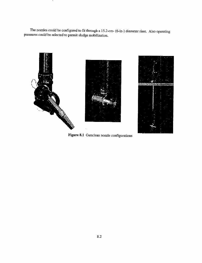
The nozzles could be contlgurecl to fit through a 15.2-cm- (6-in-) diameter riser. Also operating
pressures could be selected to permit sludge mobilization.
Figure 8.1 Gunclean nozzle confQurations
8.2

9.References
ARD Environmental, Jnc. 1996. Testing of Scavenger Systems Dislodging& Conveyance Devices.
WHC-SD-WM-TD-011, Rev. OA. Prepared by ARD Environmental, Inc., Laurel, Maryland forWestinghouse Hanford Company, Richlan4 Washington.
ARD Environmental, Inc. 1997a. Alternate Retrieval Technology Demonstrations Program – Test
Report. ~-MR-0542, Rev. O. Prepared for Lockheed Martin Hanford Company, Richlan&Washington by ARD Environmental, ?hc. Laurel, Maryland.
ARD Environmental, Inc. 1997b. Task 5 Test Report: Demonstration of Low Pressure Confined Sluicer
and Vehicles for SST Tank Wrote Retrieval at Hanford HNF-MR-0534, Rev. O. Prepared by ARDEnvironmental, Inc., Laurel, Maryland for Lockheed Martin Hanford Company, Richlan&Washington.
Barnberger, J.A. and D.E. Steele. 1993a. Developing a Scari!er to Retrieve Radioactive Wastefrom
Hanford Single-Shell T&. PNL-SA-22721. JnProceedings of the 7th American Water JetConference, Vol u Water Jet Technology Association. M Hashish, Ed. p.737-745.
Bamberger, J.A. and G.F. Boris. 1999a. Oak Ridge National Laboruto~ Old Hydrofiacture Facility
Waste Remediation Using the Borehole-Miner Extendible-Nozzle Sluicer. PNNL-12225, PacificNorthwest National Laboratory, Richlan& Washington.
Bamberger, J.A. and M.W. Rinker. 1996. Waste Retnieval System Development and Demonstration In
Proceedings of the ktemational topical Meeting on Nuclear and Hazardous Waste ManagementSpectrum 96. American Nuclear Society, Inc. La Grange ParlGIllinois. p 1921-1928.
Barnberger, J.A., D.G. Alberts, C.W. Enderlin, and M. White. 1998. Borehole Miner Extendible Nozzle
Development for Radwactive Waste Dislodging and Retrieval fiorn Underground Storage Tank
PNNL-1 1730, Pacific Northwest National Laboratory, Richlan& Washington.
Barnberger, J.A., G.F. Boris, and D.G. Alberts. 1999b. Using the Borehole Miner lhtendible-Nozzle
Sluicing System to Dislodge and Mix Settled Sludge and Supennate in the Old Hydrofiacture Td
During Remediation at Oak Ridge Ntinal Laboratory, Oak Ridge, Tennessee. American NuclearSociety, Eighth International Topical Meeting Robotics and Remote Systems, April 25-29,1999,Pittsburgh, Pemsylvania. American Nuclear Society Order No. 700271, La Grange ParlGIllinois.
Bamberger, J.A., J.M. Bates, J.K. KeslQ M.R. Ehnore, and N.J. Lombardo. 1993b. Strategy to Develop
and Test a Multi-Function Scari!er End E@ector with An Integral Conveyance System for Waste
Tmk Remediation. PNL8477, Pacific Northwest Laboratory, Richlm& Washington.
Bamberger, J.A., M.A. McKinnon, D.A. Alberts, D.E. Steele,, and C.T. Crowe. 1994. Development of a
Multi-Functional Scarifia Di..s?odger with an Integral Pneumatic Conveyance Retrieval System for
Single-Shell T& Remediation. PNL8901, Pacific Northwest Laboratory, Richlan& Washington.9.1
.- . .. .. ,.. -,.T’Z .— .-. . m-r : --- ~.-:-.,X?ZT-. .-,. ,., ,.7: ~, ..7T--- -- —--

Brothers, A.J., N.C. Williams, J.S. Dukelow, R.I. Hansen, R.D. Claghom, C.E. Grenard and R.M.Marusich. 1997. Decision Analysis for Mobilizing and Retrieving Sludgefiom Double-Shell Txk.r.
PNNL-1 1718, Pacific Northwest National Laboratory, Richland, Washington.
Carothers, K.G., S.D. Estey, N.W. Kirch, L.A. Stauffer, and J.W. Bailey. 1999. Tank 24I-C-106 Wate
Retrieval Sluicing System Process Control PZan. HNF-SD-WM-PCP-013, Rev. 2, Lockheed MartinHanford Corporation, Richlan& Washington.
Claghom, R.D. 1998. Estimated Dose to In-Td Equipment: Phase 1 Wizste Feed Delivery. HNF-
2004, Numatec Hanford Corporation, Richland, Washington.
Comads, TJ. 1998. Natural Phenomena Hazards Hanford Site, Washington. WHC-SD-GN-ER-501,
Rev. 1, Westinghouse Hanford Company, Richland, Washington.
Dahl, T.L., A.C. Lay, S.A. Taylor, and J.W. Moore. 1999. C-Tank Transfers Transuranic Sludge
Removalfiom the C-I, C-2, and W-23 Waste Storage T& at Oak Ridge National Laboratory, Oak
Ridge, Tennessee. BJC/OR-279, Bechtel Jacobs Company LLC, Oak Ridge, Tennessee.
Daymo, EA. 1997. Industrial Mixing Techniqua for Hanford Double-Shell Treks. PNNL-1 1725,Pacific Northwest National Laboratory, l?ichlan~ Washington.
Enderlin, C.W., O.D. Mullen, and G. Terrones. 1997. Performance Evaluatwn of the Quarter-Scale
Russian Retrieval Equipment for the Removal of Hazaralms Waste. PNNL-1 1740, Pacific Northwest
National Laboratory, Richlan& Washington.
Environmental Specialties Group, LLC. 1997. Hanford Td Initiative Vehicle-Based Waste Retrieval d
Demonstration Report Phase II, Track 2. HNF-MR-0544, Rev. O, Prepared for Lockheed Martin
Hanford Company, Richlan~ Washington by Environmental Specialities Group, LLC, Tulsa
Oklahoma.
Evans, MS. 1996. Issues Associated with Manipulator-Based Wrote Re~.evalfiom Hanford
Underground Storage T& with a Preliminary Review of Commercial Concepts. lWilC-SD-WM-
TA-181, Rev. OA,Westinghouse Hanford Company, Richlan~ Washington.
GrahanL RE. 1996. Test Results for Robotic Manipulator EMMA. WHC-SD-WM-TD-012, Rev. OA.Prepared by Grey Pilgrim LLC, Gaithersburg, Mruykmd for Westinghouse Hanford Company,Richlan& Washington.
Grey pilgrim LLC. 1997. Hanford Tanks Initiative Alternate Retrieval System Demonstrations – Final
Repoti of Testing Pe#orrned by Grey Pilgrim LLC. HNF-MR-0545, Rev. O, prepared for LockheedMartin Hanford Company, Richland, Washington by Grey Pilgrim LLC, Gaithersburg, Maryland.
HanIon, B.M., 1999, Waste Tank SummQry Report for Month Ending October 31, 1999, HNF-EP-O182-
139, Lockheed Martin Hanford Corporation, RichIan& Washington.
9.2

EIatchell, MC. 1997. Engineering Development of a Lightweight High-Pressure Scari~erfor T&
Wrote Retn”eval. PNNL-1 1736, Pacific Northwest National Laboratory, Richlan& Washington.
Hylton, T.D. and C.K. Bayne. 1999. Testing of In-1ine Monitors and Pz.dsaz”rMixers with Radioactive
Slum-es. ORNUI’M -1999/111, Oak Ridge National Laboratory, Oak Ridge, Temessee.
hdylG L.J. 1997. Evaluation of the Effect of Project W-151 Mixer Pump Jets on In-Td Equipment
ConsiAming Potential Sludge Buildup on Equipment in Wrote Tmk 241-AZ-101, Hanford Site,
Richland. Fluor Daniel Northwest Inc., Richlandj Washington.
Ken4 T.E., S.A. Taylor, J.W. Moore, J.L. Stellem, and K.M. Billingsley. 1998a. Demonstration of
Fluidic Pulse Jet Mixing for a Horizontal Waste Storage Td ORNLII’M -13578, Oak RidgeNational Labor?ory, Oak Ridge, Tennessee.
KenL T.E., T.D. Hylton, S.A. Taylor, and J.W. Moore. 1998b. Deployment of a Fluidic Pulse Jet MixingSystem for Horizontal Waste Storage T&at Oak Ridge National Laboratory, Oak Ridge,
Tennasee. BJC/OR-82, Bechtel Jacobs, Company LLC, Oak Ridge, Temessee.
Kirkbride, R.A., G.K. Allen, PJ. Cem A.F. Manuel, R.M. Orme, L.W. Shelton, EJ. Slaathaug, R.S.Wittman, and G.T. MacLean and D.L. Penwell (SESC), 1999, Td Waste Remediation System
Operation and Utilization PZan, HNF-SD-WM-SP-012 Rev. L VO1. I and L Numat~ H~ord
Corporation, RichIan& Washington.
LMHC. 1999a. Tank Wiz.steRemediution System Technical Safety Requirements. HNF-SD-WM-TSR- “006, Rev. 1, Lockheed Martin Hanford Corporation, Richlan& Washington.
Los Alamos Technical Associates, Inc. 1997. Advanced Sluicing System Test Report for Single Shell
Tank Waste Retrieval Integrated Testing. HIW-MR-0539, Rev. O,prepared for WestinghouseHanford Company, Richlan& W&ington by Los Alamos Technical Associates, Inc., Richkm&Washington.
Magnox Electric PLC. 1997. Results of the SN_S Manipulator andARD Sluicer Testing as pati of
Hmford Single Shell Tanks Waste Retrieval – Phase 1 –AC7R Integrated Testing.. HNF-MR-0538,
Rev. O,prepared for Fluor Daniel HanforcLRichlan& Washington by Magnox Electric plc, Berkeley,Glos, United Kingdom.
May, T.H. 1996. Tank 24I-C-106 Waste Retrieval Sluicing System (1’KRSS)Operations Manual. WHC-
SD-W320-T1-004, Westinghouse Hanford Company, Richlan& Washington.
MPW Industrial Services, Inc. 1995. Demonstrm.on of Retrieval Methods for Westinghouse Hanford
COP. October 20, 1995. WHC-MR-0526, prepared by MPW Industrial Services, Inc. forWestinghouse Hanford Company, RichIan& Washington.
9.3
- -–—-y ,, , ., ,,,,,.. ,, .,T-,.- . . . . . . . .. . .. . . —-w-=z.,.j , =- . ,, ,.,o:+ni?n: .“-. . . : . ..-. ,,; . ., .,. , --- ~ —. —.,,- I

MPW Jndustrkd Services, Inc. 1996.Corp. Trial No.2 April 30,”1996.
Demonstratz”on of Retrieval Methods for Westinghouse Hmford
WHC-MR-0527, prepared by MPW Industrial Services, Inc. forWestinghouse Hanford Company, RichIan& Washington.
Ivlullen, O.Il. 1997. Engineering Development of Waste Retn”eval End E#ectors for the Oak Ridge
Gunite Tti. PNNL-1 1586, Pacific Northwest National Laboratory, Richlan& Washington.
Mullen, O.D. 1997. Field Pe#ormance of the Wate Retrieval End Effecters in the Oak Ridge Gunite
Tanks. PNNL-1 1688, Pacific Northwest National Laboratory, Richlan& Washington.
Murray, P. and H. Peters. 1999. Emptying Of C-Tanks At Oak Ridge Reservation Utilizing Pulse Jet
Mixing. American Nuclear Society, Eighth International Topical Meeting Robotics and Remote
Systems, April 25-29,1999, Pittsburgh, Pemsylvania. American Nuclear Society Order No. 700271,
La Grange Park Illinois.
Noorani, Y.G. and G.W. Ryan. 1997. Tank Waste Remedi.ation System Bases for Interim Operation.
HNF-SD-WM-BIO-001 Rev O, Lockheed Martin Hanford Company, Richland, Washington.
Powell, M.R. 1996. Initial ACIX Retr+eval Technology Evaluation Test Mat’erial Recommendations.
PNNL-1 1021, Pacific Northwest National Laboratory, Richlan~ Washington.
Powell, M.R. 1997. Retrieval Process Development and Enhancewnts Pulsed-Air Mixing DOE Site
Assessment. PNNL-1 1584, Pacific Northwest National Laboratory, Richland, Washington.
Powell, M.R and C.R Hymas. 1996. Retrieval Process Development and Enhancements FY96 Pulsed-
Air Mixer Testing and Deployment Study. I?NNL-1 1200, Pacific Northwest National Laboratory,
Richlan~ Washington.
Powell, M.R., G.R. Golcar, and J.G.H. Ge&ing. 1997. Rebilwal Process Developnumt and
Enhancements Waste sinudant Compositions and Defensibility. PNNL-1 1685, Pacific Northwest
National Laboratory, Richlan~ Washington.
Powell, M.R., J.R. Farmer, H. Gladki, B.K. Hatchell, M.R. Poirier, and P.O. Rodwell. 1999a. Evaluadon
of Flygt Mixers for Application in Savannah River Site Tank ]9, Test Results@om Phase A: Small-
Scale Testing at Z!T Flygt. PNNL-12094, Pacific Northwest National Laboratory, Richkmd,
Washington.
Powell, M.R., J.R. Farmer, H. Gladki, B.K. Hatchell, M.A. Johnson, M.R. Poirier, and P.O. Rodwell.1999b. Evaluation of Flygt Mixers for Application in Savannah River Site Tank 19, Summary of Test
Resultsfiom Phase A, B, and C Testing. PNNL-12168, Pacific Northwest National Laboratory,
RichlanL Washington.
PowelI, M.R., W.H. Combs, J.R. Farmer, H. Gladki, M.A. Johnson, B.K. Hatchell, M.R. Pokier, and P.O.
Rodwell. 1999c. Evalti.on of Flygt Mtirs for Application in Savannah River Site Tank 19, Test
9.4

, Resultsfiom Phase B: Mid-Scale Testing at PNNL PNNL-12093, Pacific Northwest NationalLaboratory, RichIan& Washington.
Powell, M.R., Y. Onishi, and R. Shekarriz. 1997. Research on Jet Mixing of Settled Sludges in Nuclear
Wrote T&at Hanford and Other DOE Sites: A Historical Perspective. PNNL-I 1686, PacificNorthwestNational Laboratory,RichIan&Washington.
RamSower, D.C. 1996. Sluicing Nozzle Test Report, Volume 1. WHC-SD-WM-TD-013, Rev. OAWestinghouse HanforL Company, Richlam$ Washington.
Rarnsower, D.C. 1996. Test Results for Robotic Manipulator EMMA. WHC-SD-WM-TD-012, Rev. O,Westinghouse Hanford Company, Richlan& Washington.
Rasumssen, O.R. 1998. Waste Feed Delivery Technical Basis, Volume Ill Waste Feed Delivery System
Description. HNF-1939, Vol. ~ Rev. O,Lockheed Martin Hanford Corporation, RichlandWashington.
Rinker, M.W., B.K. Hatchell, M.R. Powell, J.H. Lee, G. Healey, P.W. Gibbons. 1999. Retrieval of
Uranium Sludgefiom an Iraqi Tank American Nuclear Society, Eighth International TopicalMeeting Robotics and Remote Systems, April 25-29,1999, Pittsburgh, Pennsylvania- American
, Nuclear Society Order No. 700271, La Grange ParlGIllinois.
Rinker, M.W., D.G. Alberts, J.A. Bamberger, B.K. Hatchell, K.I. Johnson, O.D. Mullen, M.R. Powell,D.A. Summers. 1996. Treks Focus Area Retrieval Process Development and Enhancements FY96
Technology Development Summary Repoti. PNNL-1 1349, Pacific Northwest National Laboratory,Richlan& Washington.
Rinker, M.W., D.G. Alberts, J.A. Bamberger, E.A. Daymo, C.W. Enderlin, F.F. Brian, B.K. Hatchell, K.I.Johnson, O.D. Mullen, M.R. Powell, D.A. Summers. 1997. EM-SOTanks Focus Area Retrieval
Process Development and Enhancements FY97 Technology Development Sumnuzry Repoti. PNNL-11734, Pacific Northwest National Laboratory, Richlan& Washington.
Rule, V.A., B.L. Burkes, S.D. Van Hoesen. 1998. The North Tank Farm Data Report for the Gunite andAssociated Tanks at Oak Ridge National Laboratory, Oak Ridge, Tennessee. ORNIXTM-13630, OakRidge National Laboratory, Oak Ridge, Temessee.
Tedeschi, A.R. 2000. Derived Requirements for Double-Shell Tank High-&vel Waste Auxiliary Solids
Mobilization. RPP-5664, Rev. O,CH2M Hill Hanford Group, Ihc. Richland Washington.
Whyat4 G.A. and C.R. Hymas. 1997. Bench-Scale feasibility Testing of Pulsed-Air Technology for In-
Tmk Mixing of Dry Cementitious Solids with T& Liquk?.s and Settled Solids. PNNL-I 1690, PacificNorthwest National Laboratory, Richlan~ Washington.
WSRC. 1997. Basis for Interim Operation (BIO) for Liquid Radioactive Waste Handling Facilities.
WSRC-RP-94-346, Rev. 3, Westinghouse Savannah River Company, Aiken, South Carolina.
9.5
.,-...-Z-. ..m-,.-, , . . ., ,,. . . . . . .. . . . ,,, 7—. , , .-km-. -,, ~-. I
PNNL-13048
D~tribution
No. of No. of
Qm2 Q!Q@i
OFFSITB OFFSITE
1
1
1
2
1
I 1
1
2
DOE/OflkeofScientific andTecbnical 1
Information and Information Release
S. Barnes10282 Rock Springs Rd. MSN WV48West Valley, NY 14171
F. Damerow 1
10282 Rock Springs Rd.West Valley, NY 14171-9799
N. R DavisWestinghouse Savannah River Company703-H Bldg.Aiken, SC 29801 1
P?L. DavisWestinghouse Savannah River Company742-9G Bldg.Aiken, SC 29801
1J. R Noble-DialU.S. Departmentof EnergyOak Ridge OperationsOfliceP.O. Box 2001Oak Ridge, TN 37830-8620 1
J. L. Drake, JrWest Valley 10282 Rock Springs Rd.West Valley, NY 14171
J. R Farmer 1
Oak Ridge National LaboratoryBethel Valley Rod Bldg. 1000 (MS 6341)Oak Ridge, TN 37831
DlstT. 1
D. W. Geiir, EM-50US Departmentof EnergyTanks FOCUS Area
Cloverleaf Building19901 GermantownRoadGermantown,MD 20874-1290
K. GerdesOffice of Science and TechnologyProgramManager– Tanks Focus Area19901 GermantownRoad1154/Cloverleaf Bldg.Germantown,MD 20874-1290”
T. S. GutmannU.S. Departmentof EnergySavannahRiver OperationsOfficeP.O. BOXi%Bldg. 704-SAiken, SC 29802
H. M. HandflngerWestinghouse Savannah River Company704-S Bldg.Aiken, SC 29801
M. JensenLockheed Martin Idaho TechnologiesCompanyP.O. BOX1625, MS 3204ICkihO,Falls, ID 83415-3204
M. A. JohnsonOakRidge National LaboratoryP.O. BOX2008, MS 6306Oak Ridge, TN 37831-6306
—-.-— .. .. . . . . . . .. . -.<-7-=-’ .,”
,—..,——-----% —-—
. . . - ,, ..:- -x.,- l-..x. > 7.- ,..,, ,, . . . .. . . ,. , , ... . . .-,. ,., ~ ..> .<,,.

PNNL-13048
No. of
Q!2Q&
OFFSITE1
1
1
1
1
T. J. h?XWestinghouse Savannah River Co.Savannah River Technology Center703-H BuildingAiken, SC 29808
B.A. Martin
Distribution
No. of
-
OFFSITE
1
Westinghouse Savannah River Company742-9G Bldg. 1Aiken, SC 29801
T. M. MonahonWestinghouse SavannahRiver Co.Savannah River Technology Center 1703-H Building
Aiken, SC 29808
J. P. MorinWestinghouse Savannah River Co.Savannah River Tedmolo~ Center 1703-H BuildingA&en, SC 29808
S. M. Robinson, MS-6(M4Martin Marietta Energy Systems, Inc.Oak Ridge National LaboratoryP.O. BOX2008Oak Ridge, TN 37831
P. w. WOOI,MS-1145Idaho National Engineering and
Environmental LabOmtOIY .
U.S. Department of Energy750 DOE PlaceIdaho Falls, ID 83402
A.M. Jensen, MS-3204Lockheed Martin Idaho Technology Co.P.O. BOX1625Ida.hOFalls, ID 83415-3204
T. S. GutmannU.S. Department of EnergySavannah River Operations OfficeP.O. Box AAiken, SC 29802
B. E. Lewis, Jr.Oak Ridge National LaboratoryP.O. BOX2008, MS6305Oak Ridge, TN 37831-6305
Distr. 2

PNNL-13048
DistributionI
No. of
Q&
ONSITE
20 Hanford SiteE. J. BerglinA. B. CarlsonP. J. CertaA. F. ChohoT. J. C!onradsJ. S. GarfieldM. G. GlasperJ. O. HoneyrnanC. SoLOuieE. A. Pacquet (5)C. P. Shaw (2)A. R. TedeschiW. T. ThompsonR. L. TreatW. L. Willis
H3-26R3-73R3-73R3-73R3-73R3-73K8-50H6-18H6-60R347S7-70R1-31R3-73H6-19R3-73
8 Tanks Focus Area Technical TeamB. J. Williams K9-69
No. of
Q&
ONSITE
2 Retrieval Technology IntegrationManagerP. W. Gibbons K9-91
1 Tanks Focus Area Field LeadT. P. Pietrok K8-50
25 Paciiic Northwest National LaboratoryK. M. Airhart(4) K5-22J. A. Bamberger(6) K7-15W. F. Bonner K9-14J. L. Buelt K9-09B.A. Carteret K9-91C. W. Enderlin K7-15F. F. Erian K7-15B. K. Hatchel K5-22W. L. Kuhn K7-15O. D. Mullen K5-22M. W. Rinker(6) K5-22G. A. W’hyatt K6-24
Distr. 3
——_,. .-T ,----..=,=..--, .-,,.,’ .-..7. -.=.-. -..2 . T.-—r,,.=-: ,- - --- --- -
——..