gx-86 manual (0398)
TRANSCRIPT
RKI Instruments, Inc. • 33248 Central Ave. Union City, CA 94587 • (510) 441-5656
Instruction ManualModel GX-86
Portable Four Gas Monitor
Part Number: 71-0001RK
Edition: Second
Released: March 1998

ii • Warranty Model GX-86 Operator’s Manual
Warranty
RKI Instruments, Inc., warranties gas alarm equipment manufactured by RKI and sold by RKI to be free from defects in materials and workmanship for a period of one year from date of shipment from RKI Instruments, Inc. Any parts found defective within that period will be repaired or replaced, at our option, free of charge. This warranty does not apply to items that are subject to deterioration or consumption in normal service, and which must be cleaned, repaired, or replaced routinely. Those items include, but are not limited to:
This warranty is voided by mechanical damage, misuse, alteration, rough handling, or repairs not in accordance with the operator’s manual. This warranty indicates the full extent of our liability. We are not responsible for removal or replacement costs, local repair costs, transportation costs, or contingent expenses incurred without our prior approval.
THIS WARRANTY IS IN LIEU OF ANY OTHER WARRANTIES AND REPRESENTATIONS, EXPRESSED OR IMPLIED, AND ALL OTHER OBLIGATIONS OR LIABILITIES ON THE PART OF RKI INSTRUMENTS, INC., INCLUDING BUT NOT LIMITED TO THE WARRANTY OF MERCHANTABILITY OR FITNESS FOR A PARTICULAR PURPOSE. IN NO EVENT SHALL RKI INSTRUMENTS, INC., BE LIABLE FOR INDIRECT, INCIDENTAL, OR CONSEQUENTIAL LOSS OR DAMAGE OF ANY KIND CONNECTED WITH THE USE OF ITS PRODUCTS OR FAILURE OF ITS PRODUCTS TO FUNCTION OR OPERATE PROPERLY.
This warranty covers instruments and parts sold to end users by authorized distributors, dealers, and representatives of RKI Instruments, Inc.
We do not assume indemnification for any accident or damage caused by the operation of this gas monitor. Our warranty is limited to replacement of parts or our complete goods.
absorbent cartridges filter elements
pump diaphragms and valves batteries
lamp bulbs and fuses

Model GX-86 Operator’s Manual Table of Contents • iii
Table of Contents
Introduction . . . . . . . . . . . . . . . . . . . . . . . . . . . . . . . . . . . . . . . . . . . . . . . . . . . . . . . . . . . . . . . . . 1
Description. . . . . . . . . . . . . . . . . . . . . . . . . . . . . . . . . . . . . . . . . . . . . . . . . . . . . . . . . . . . . . . . . . 1
Components and Controls. . . . . . . . . . . . . . . . . . . . . . . . . . . . . . . . . . . . . . . . . . . . . . . . . . . . . 2Case. . . . . . . . . . . . . . . . . . . . . . . . . . . . . . . . . . . . . . . . . . . . . . . . . . . . . . . . . . . . . . . . . . . . . . . . . . . . . . . . . 2Sensors . . . . . . . . . . . . . . . . . . . . . . . . . . . . . . . . . . . . . . . . . . . . . . . . . . . . . . . . . . . . . . . . . . . . . . . . . . . . . . 2Accessory Jacks . . . . . . . . . . . . . . . . . . . . . . . . . . . . . . . . . . . . . . . . . . . . . . . . . . . . . . . . . . . . . . . . . . . . . . . 3Control Panel. . . . . . . . . . . . . . . . . . . . . . . . . . . . . . . . . . . . . . . . . . . . . . . . . . . . . . . . . . . . . . . . . . . . . . . . . 4Buzzer. . . . . . . . . . . . . . . . . . . . . . . . . . . . . . . . . . . . . . . . . . . . . . . . . . . . . . . . . . . . . . . . . . . . . . . . . . . . . . . 4Battery Compartment. . . . . . . . . . . . . . . . . . . . . . . . . . . . . . . . . . . . . . . . . . . . . . . . . . . . . . . . . . . . . . . . . . 4Circuit Boards . . . . . . . . . . . . . . . . . . . . . . . . . . . . . . . . . . . . . . . . . . . . . . . . . . . . . . . . . . . . . . . . . . . . . . . . 4
Operation . . . . . . . . . . . . . . . . . . . . . . . . . . . . . . . . . . . . . . . . . . . . . . . . . . . . . . . . . . . . . . . . . . . 5Preparation. . . . . . . . . . . . . . . . . . . . . . . . . . . . . . . . . . . . . . . . . . . . . . . . . . . . . . . . . . . . . . . . . . . . . . . . . . . 5Start-up. . . . . . . . . . . . . . . . . . . . . . . . . . . . . . . . . . . . . . . . . . . . . . . . . . . . . . . . . . . . . . . . . . . . . . . . . . . . . . 5Normal Operation. . . . . . . . . . . . . . . . . . . . . . . . . . . . . . . . . . . . . . . . . . . . . . . . . . . . . . . . . . . . . . . . . . . . . 6Alarms . . . . . . . . . . . . . . . . . . . . . . . . . . . . . . . . . . . . . . . . . . . . . . . . . . . . . . . . . . . . . . . . . . . . . . . . . . . . . . 7Safety Self-Check. . . . . . . . . . . . . . . . . . . . . . . . . . . . . . . . . . . . . . . . . . . . . . . . . . . . . . . . . . . . . . . . . . . . . . 8Emergency Operation . . . . . . . . . . . . . . . . . . . . . . . . . . . . . . . . . . . . . . . . . . . . . . . . . . . . . . . . . . . . . . . . . 8
Calibration . . . . . . . . . . . . . . . . . . . . . . . . . . . . . . . . . . . . . . . . . . . . . . . . . . . . . . . . . . . . . . . . . . 9Supplies and Equipment . . . . . . . . . . . . . . . . . . . . . . . . . . . . . . . . . . . . . . . . . . . . . . . . . . . . . . . . . . . . . . . 9Calibrating the GX-86. . . . . . . . . . . . . . . . . . . . . . . . . . . . . . . . . . . . . . . . . . . . . . . . . . . . . . . . . . . . . . . . . . 9Calibration with the RKI Four-Gas Cylinder . . . . . . . . . . . . . . . . . . . . . . . . . . . . . . . . . . . . . . . . . . . . . 11
Maintenance. . . . . . . . . . . . . . . . . . . . . . . . . . . . . . . . . . . . . . . . . . . . . . . . . . . . . . . . . . . . . . . . 12Batteries . . . . . . . . . . . . . . . . . . . . . . . . . . . . . . . . . . . . . . . . . . . . . . . . . . . . . . . . . . . . . . . . . . . . . . . . . . . . 12CO Filter. . . . . . . . . . . . . . . . . . . . . . . . . . . . . . . . . . . . . . . . . . . . . . . . . . . . . . . . . . . . . . . . . . . . . . . . . . . . 12Sensor Maintenance . . . . . . . . . . . . . . . . . . . . . . . . . . . . . . . . . . . . . . . . . . . . . . . . . . . . . . . . . . . . . . . . . . 12Sensor Replacement . . . . . . . . . . . . . . . . . . . . . . . . . . . . . . . . . . . . . . . . . . . . . . . . . . . . . . . . . . . . . . . . . . 13
Accessories . . . . . . . . . . . . . . . . . . . . . . . . . . . . . . . . . . . . . . . . . . . . . . . . . . . . . . . . . . . . . . . . . 14Extender Cable . . . . . . . . . . . . . . . . . . . . . . . . . . . . . . . . . . . . . . . . . . . . . . . . . . . . . . . . . . . . . . . . . . . . . . 14Sample-Draw Aspirator. . . . . . . . . . . . . . . . . . . . . . . . . . . . . . . . . . . . . . . . . . . . . . . . . . . . . . . . . . . . . . . 14Sample-Draw Pump. . . . . . . . . . . . . . . . . . . . . . . . . . . . . . . . . . . . . . . . . . . . . . . . . . . . . . . . . . . . . . . . . . 15
Appendix A: Parts List . . . . . . . . . . . . . . . . . . . . . . . . . . . . . . . . . . . . . . . . . . . . . . . . . . . . . . . 16
Appendix B: RKI Model GX-86 Relative Response Chart . . . . . . . . . . . . . . . . . . . . . . . . 17

iv Model GX-86 Operator’s Manual

Model GX-86 Instruction Manual Introduction • 1
Introduction
The RKI Model GX-86 is a proven gas detection instrument, in use internationally for personal protection in a wide variety of industries. The GX-86 is compact, convenient, and offers a full range of features, including:
• simultaneous detection of combustible gas (% LEL,) oxygen deficiency (O
2
), carbon monoxide (CO), and hydrogen sulfide (H
2
S)
• dot-matrix display for complete, understandable information at a glance
• distinctive audible alarms for dangerous conditions and malfunctions
• intrinsic safety for Class I, Division I, Group C and D hazardous atmospheres
• microprocessor control for reliability, ease of use, and advanced capabilities
• small size and light weight for user comfort
WARNING: The GX-86 is designed to detect combustible gas, oxygen deficiency, hydrogen sulfide, and carbon monoxide, which can be life threatening. Users must follow the instructions and warnings in this manual to assure
proper and safe operation of the GX-86.
Description
The RKI Model GX-86 is an advanced portable instrument for simultaneous detection of combustible gas (LEL), oxygen deficiency (O
2
), carbon monoxide (CO), and hydrogen sulfide (H
2
S) See Table 1 for detection ranges. Gas detection features include distinctive alarms for dangerous gas concentrations and time-weighted averaging for exposure to toxic gases (H
2
S and CO).
The GX-86 is compact enough to be worn on a belt loop or shoulder strap, which leaves your hands free. It has a tough plastic housing, touch-pad control panel, back-lit display, and comes with a vinyl carrying case.
The GX-86 is easy to adjust and maintain. The batteries and diffusion sensors are user-replaceable. The GX-86 also displays battery condition and sensor malfunction during start-up and operation.
Table 1: Ranges of Target Gases
Gas Detected Range
Combustible 0 to 100% LEL
1
Oxygen 0 to 40%
Hydrogen sulfide 0 to 100 ppm
2
Carbon monoxide 0 to 300 ppm
1
LEL (Lower Explosive Limit)
2
ppm (Parts Per Million)

2 • Components and Controls Model GX-86 Instruction Manual
Components and Controls
This section describes the GX-86’s components and user controls.
Case
The GX-86 has a rigid plastic case that is durable and shock-resistant. The sensors are housed in a metal diffusion head at the bottom of the GX-86. The touch-pad control panel and display are located on the top. The carrying case has openings for the diffusion grill, buzzer, remote alarm, earphone jack, and control panel. The case includes a belt loop and shoulder strap loops.
Sensors
The sensors are mounted in the diffusion head at the bottom of the GX-86. The diffusion grill protects the sensors. The grill easily snaps off the instrument case so you can conveniently replace the sensors.
Combustible gas sensor
The combustible gas (LEL) sensor is contained in a metal cylindrical shell, with a bayonet-pin base for easy replacement. The perforations at the end of the shell allow atmosphere to diffuse into the sensor.
Combustible gas sensor - principle of operation
The LEL sensor is a platinum-coated resistive element, with a non-catalytic, electrically identical reference element, to compensate for temperature variations and other environmental factors. The elements are housed in a sintered stainless steel flame arrestor that permits the atmosphere to diffuse inward but prevents flame to pass outward when an explosive atmosphere is encountered. The two elements form half of a balanced Wheatstone Bridge. When voltage is applied to the elements, combustible gas in the atmosphere catalyzes on the platinum coating, raising the temperature and changing the resistance of the element, causing an imbalance in the Wheatstone Bridge. The imbalance is measured by the GX-86’s circuitry and converted to a measurement of gas concentration.
Oxygen sensor
The oxygen (O
2
) sensor is contained in a cylindrical metal shell, with a bayonet pin base for easy replacement. The shell forms one electrical contact, and a button on the base is the other contact. The perforations at the end of the shell allow atmosphere to diffuse into the sensor.
Oxygen sensor - principle of operation
The O
2
sensor is an electrochemical cell. It consists of gold and lead electrodes in an alkaline electrolyte. A fluorocarbon membrane covers the cell and allows atmosphere to diffuse into the electrolyte at a rate proportional to the partial pressure of oxygen. The oxygen reacts in the cell, producing a current proportional to the concentration of oxygen. The current develops a voltage across a temperature-compensating thermistor/resistor network. The voltage is measured by the GX-86’s circuitry and converted to a measurement of gas concentration.

Model GX-86 Instruction Manual Components and Controls • 3
CO and H
2
S sensors
The CO and H
2
S sensors are physically identical, except for their external labels. The sensors are housed in a cylindrical plastic shell, with a bayonet-pin base for easy replacement. The perforations at the end of the shell allow atmosphere to diffuse into the sensor. The CO sensor also has a slip-on charcoal filter that covers the diffusion end. The filter eliminates interference from H
2
S.
CO and H
2
S sensors - principle of operation
The CO and H
2
S sensors are electrochemical cells, consisting of two precious metal electrodes in an acid electrolyte. A gas permeable membrane covers the cell and allows gas in the atmosphere to diffuse into the electrolyte at a rate proportional to its partial pressure. The gas reacts in the cell, producing a current proportional to the concentration of gas. The current is amplified by the GX-86’s circuitry and converted to a measurement of gas concentration. To maintain sensitivity and stability, the CO and H
2
S sensors are exposed to a continuous bias current, even when the power is off.
Accessory Jacks
Two 2.5 mm accessory jacks are located at the bottom of the GX-86 on either side of the diffusion head.
Buzzer jack
The buzzer jack is located to the right of the diffusion head. You can use this jack to connect an extension buzzer.
Earphone jack
The earphone jack is located to the left of the diffusion head. You can use this jack to connect an extension earphone.
4 • Components and Controls Model GX-86 Instruction Manual
Control Panel
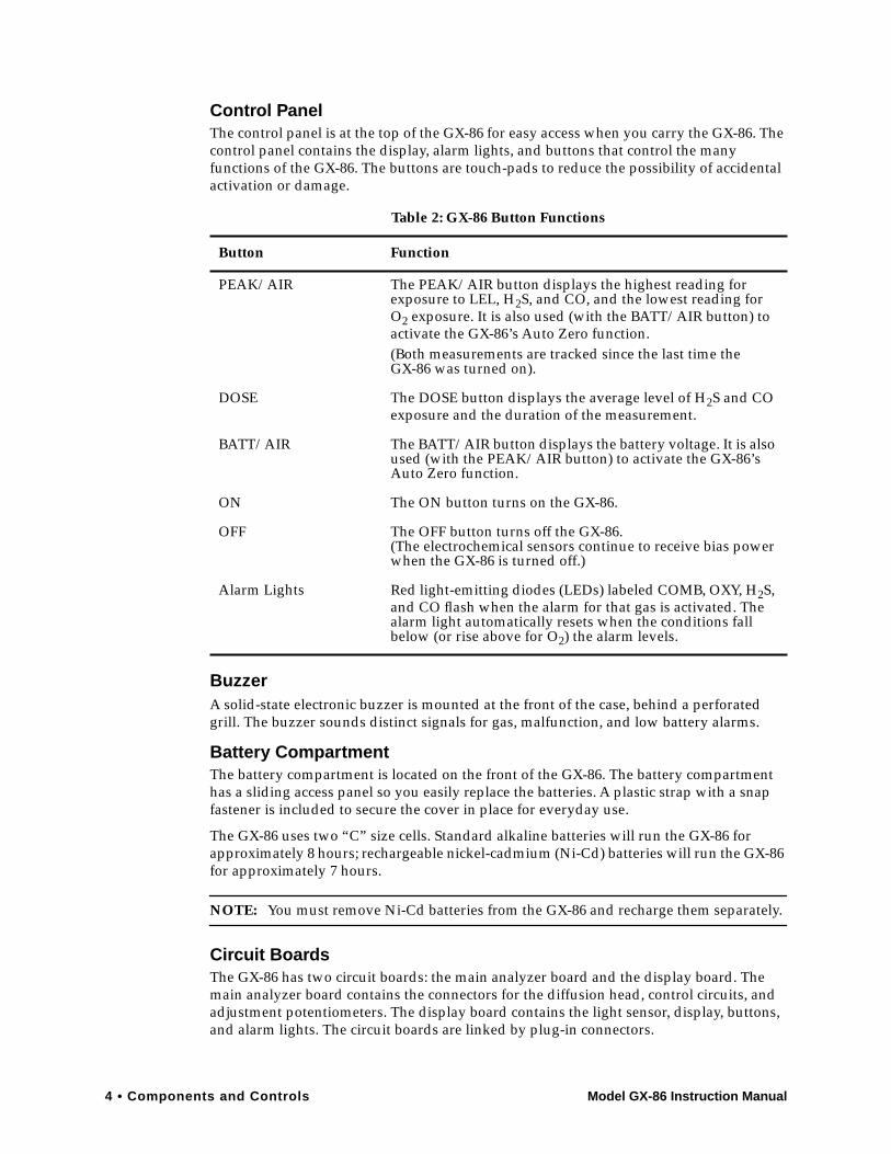
The control panel is at the top of the GX-86 for easy access when you carry the GX-86. The control panel contains the display, alarm lights, and buttons that control the many functions of the GX-86. The buttons are touch-pads to reduce the possibility of accidental activation or damage.
Buzzer
A solid-state electronic buzzer is mounted at the front of the case, behind a perforated grill. The buzzer sounds distinct signals for gas, malfunction, and low battery alarms.
Battery Compartment
The battery compartment is located on the front of the GX-86. The battery compartment has a sliding access panel so you easily replace the batteries. A plastic strap with a snap fastener is included to secure the cover in place for everyday use.
The GX-86 uses two “C” size cells. Standard alkaline batteries will run the GX-86 for approximately 8 hours; rechargeable nickel-cadmium (Ni-Cd) batteries will run the GX-86 for approximately 7 hours.
NOTE:
You must remove Ni-Cd batteries from the GX-86 and recharge them separately.
Circuit Boards
The GX-86 has two circuit boards: the main analyzer board and the display board. The main analyzer board contains the connectors for the diffusion head, control circuits, and adjustment potentiometers. The display board contains the light sensor, display, buttons, and alarm lights. The circuit boards are linked by plug-in connectors.
Table 2: GX-86 Button Functions
Button Function
PEAK/AIR The PEAK/AIR button displays the highest reading for exposure to LEL, H
2
S, and CO, and the lowest reading for O
2
exposure. It is also used (with the BATT/AIR button) to activate the GX-86’s Auto Zero function.(Both measurements are tracked since the last time theGX-86 was turned on).
DOSE The DOSE button displays the average level of H
2
S and CO exposure and the duration of the measurement.
BATT/AIR The BATT/AIR button displays the battery voltage. It is also used (with the PEAK/AIR button) to activate the GX-86’s Auto Zero function.
ON The ON button turns on the GX-86.
OFF The OFF button turns off the GX-86.(The electrochemical sensors continue to receive bias power when the GX-86 is turned off.)
Alarm Lights Red light-emitting diodes (LEDs) labeled COMB, OXY, H
2
S, and CO flash when the alarm for that gas is activated. The alarm light automatically resets when the conditions fall below (or rise above for O
2
) the alarm levels.
Model GX-86 Instruction Manual Operation • 5
Operation
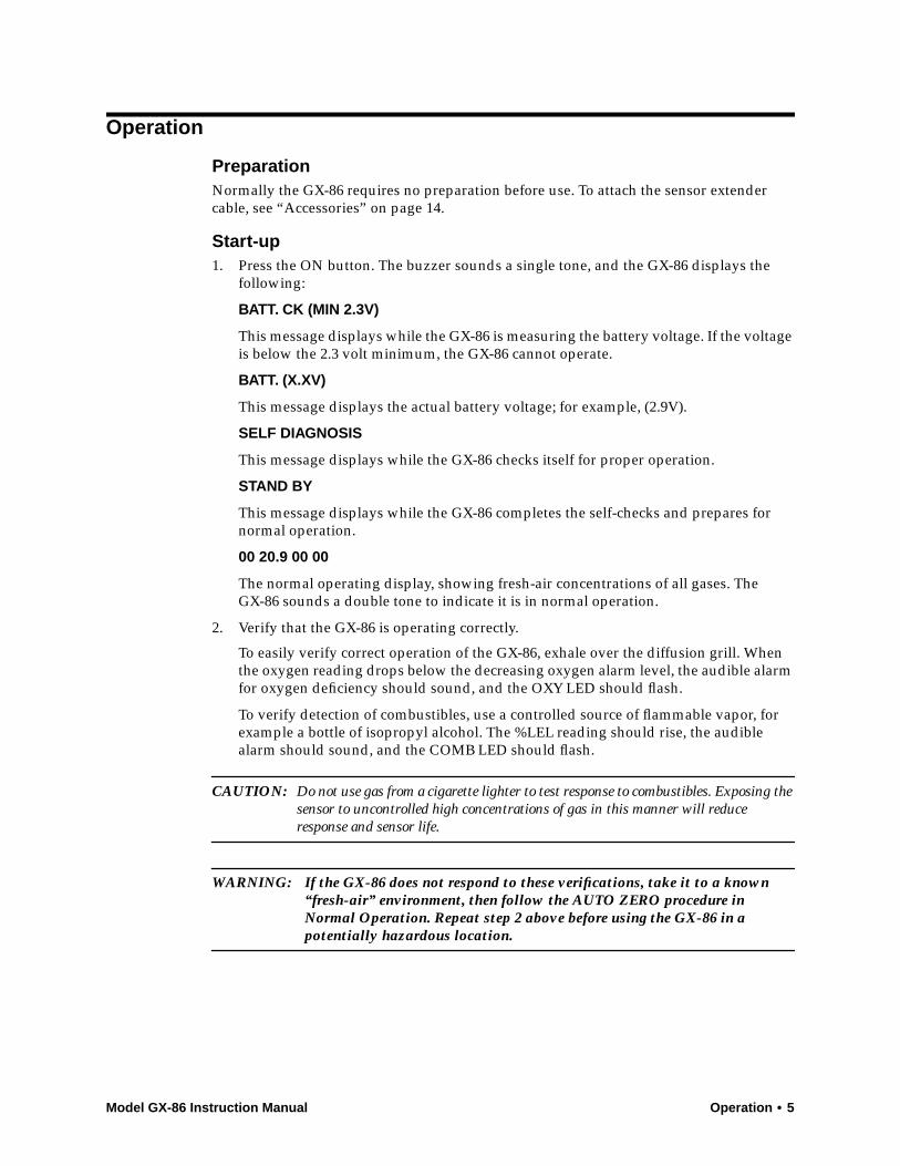
Preparation
Normally the GX-86 requires no preparation before use. To attach the sensor extender cable, see “Accessories” on page 14.
Start-up
1. Press the ON button. The buzzer sounds a single tone, and the GX-86 displays the following:
BATT. CK (MIN 2.3V)
This message displays while the GX-86 is measuring the battery voltage. If the voltage is below the 2.3 volt minimum, the GX-86 cannot operate.
BATT. (X.XV)
This message displays the actual battery voltage; for example, (2.9V).
SELF DIAGNOSIS
This message displays while the GX-86 checks itself for proper operation.
STAND BY
This message displays while the GX-86 completes the self-checks and prepares for normal operation.
00 20.9 00 00
The normal operating display, showing fresh-air concentrations of all gases. TheGX-86 sounds a double tone to indicate it is in normal operation.
2. Verify that the GX-86 is operating correctly.
To easily verify correct operation of the GX-86, exhale over the diffusion grill. When the oxygen reading drops below the decreasing oxygen alarm level, the audible alarm for oxygen deficiency should sound, and the OXY LED should flash.
To verify detection of combustibles, use a controlled source of flammable vapor, for example a bottle of isopropyl alcohol. The %LEL reading should rise, the audible alarm should sound, and the COMB LED should flash.
CAUTION:
Do not use gas from a cigarette lighter to test response to combustibles. Exposing the sensor to uncontrolled high concentrations of gas in this manner will reduce
response and sensor life.
WARNING: If the GX-86 does not respond to these verifications, take it to a known “fresh-air” environment, then follow the AUTO ZERO procedure in Normal Operation. Repeat step 2 above before using the GX-86 in a
potentially hazardous location.

6 • Operation Model GX-86 Instruction Manual
Normal Operation
The GX-86 continuously monitors the atmosphere and displays the LEL, O
2
, H
2
S, and CO concentrations present. If the GX-86 is taken into a low-light environment, the display backlight automatically turns on.
Displaying battery voltage
Press the BATT button. A single tone sounds and the battery voltage displays. New alkaline batteries will register approximately 3.0V; freshly recharged Ni-Cd batteries will register approximately 2.7V. The minimum voltage required for the GX-86 is 2.3V.
NOTE:
The GX-86 automatically checks battery voltage during start-up. If the measurement is below 2.3V, the GX-86 will not operate.
During normal operation, when the battery voltage drops to 2.3V, the letter
B
flashes on the display to indicate a low battery warning. When the voltage reaches 2.1V, all four LEDs turn on, a continuous alarm tone sounds, and
LOW BATT
displays.
WARNING: The GX-86 does not monitor the atmosphere during the low battery alarm. When the
B
indicator flashes on the display, take the GX-86 to a non-
hazardous location to change the batteries. (See Maintenance-Batteries.)
Displaying toxic gas (H
2
S and CO) exposure
Press the DOSE button. A single tone sounds and the GX-86 displays
AVG XX M XX XXX
. This display indicates the duration of the measurement in minutes (
XX M
), and the H
2
S and CO average exposure during that time. The GX-86 returns to normal operation after five seconds. The duration of the measurement is the time elapsed since the last time the GX-86 was turned on.
Displaying peak readings
Press the PEAK button. A single tone sounds and the letter
P
and readings for all four gases display. The readings are the highest (lowest for O
2
) concentrations detected since the GX-86 was turned on.
The GX-86 displays the peak readings for five seconds then returns to normal operation. Peak readings stay in the GX-86’s memory until a higher level is detected or the GX-86 is turned off.
NOTE:
The BATT (battery voltage) and DOSE (toxic exposure) functions do not work
while the GX-86 is in the PEAK display condition.
Auto zero/span
To automatically adjust the zero point for combustibles, H
2
S, and CO, and the span for oxygen, take the GX-86 to a known fresh air environment. With the GX-86 in normal operation, press and hold the BATT/AIR and PEAK/AIR buttons at the same time until a double tone sounds. The GX-86 displays
AUTO ZERO/SPAN
, which indicates the GX-86 is adjusting the detection circuits based upon the fresh air reading. When
AUTO ZERO/SPAN
displays, release the BATT/AIR and PEAK/AIR buttons.
Model GX-86 Instruction Manual Operation • 7
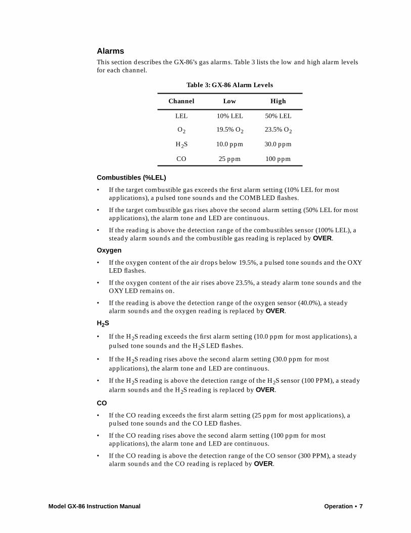
Alarms
This section describes the GX-86’s gas alarms. Table 3 lists the low and high alarm levels for each channel.
Combustibles (%LEL)
• If the target combustible gas exceeds the first alarm setting (10% LEL for most applications), a pulsed tone sounds and the COMB LED flashes.
• If the target combustible gas rises above the second alarm setting (50% LEL for most applications), the alarm tone and LED are continuous.
• If the reading is above the detection range of the combustibles sensor (100% LEL), a steady alarm sounds and the combustible gas reading is replaced by
OVER
.
Oxygen
• If the oxygen content of the air drops below 19.5%, a pulsed tone sounds and the OXY LED flashes.
• If the oxygen content of the air rises above 23.5%, a steady alarm tone sounds and the OXY LED remains on.
• If the reading is above the detection range of the oxygen sensor (40.0%), a steady alarm sounds and the oxygen reading is replaced by
OVER
.
H
2
S
• If the H
2
S reading exceeds the first alarm setting (10.0 ppm for most applications), a pulsed tone sounds and the H
2
S LED flashes.
• If the H
2
S reading rises above the second alarm setting (30.0 ppm for most applications), the alarm tone and LED are continuous.
• If the H
2
S reading is above the detection range of the H
2
S sensor (100 PPM), a steady alarm sounds and the H
2
S reading is replaced by
OVER
.
CO
• If the CO reading exceeds the first alarm setting (25 ppm for most applications), a pulsed tone sounds and the CO LED flashes.
• If the CO reading rises above the second alarm setting (100 ppm for most applications), the alarm tone and LED are continuous.
• If the CO reading is above the detection range of the CO sensor (300 PPM), a steady alarm sounds and the CO reading is replaced by
OVER
.
Table 3: GX-86 Alarm Levels
Channel Low High
LEL 10% LEL 50% LEL
O
2
19.5% O
2
23.5% O
2
H
2
S 10.0 ppm 30.0 ppm
CO 25 ppm 100 ppm
8 • Operation Model GX-86 Instruction Manual
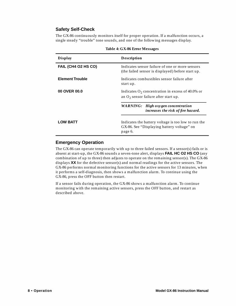
Safety Self-Check
The GX-86 continuously monitors itself for proper operation. If a malfunction occurs, a single steady “trouble” tone sounds, and one of the following messages display.
Emergency Operation
The GX-86 can operate temporarily with up to three failed sensors. If a sensor(s) fails or is absent at start-up, the GX-86 sounds a seven-tone alert, displays
FAIL HC O2 HS CO
(any combination of up to three) then adjusts to operate on the remaining sensor(s). The GX-86 displays
XX
for the defective sensor(s) and normal readings for the active sensors. The GX-86 performs normal monitoring functions for the active sensors for 13 minutes, when it performs a self-diagnosis, then shows a malfunction alarm. To continue using theGX-86, press the OFF button then restart.
If a sensor fails during operation, the GX-86 shows a malfunction alarm. To continue monitoring with the remaining active sensors, press the OFF button, and restart as described above.
Table 4: GX-86 Error Messages
Display Description
FAIL (CH4 O2 HS CO)
Indicates sensor failure of one or more sensors (the failed sensor is displayed) before start up.
Element Trouble
Indicates combustibles sensor failure afterstart up.
00 OVER 00.0
Indicates O
2
concentration in excess of 40.0% or an O
2
sensor failure after start up.
WARNING: High oxygen concentration
increases the risk of fire hazard.
LOW BATT Indicates the battery voltage is too low to run the GX-86. See “Displaying battery voltage” on page 6.

Model GX-86 Instruction Manual Calibration • 9
Calibration
The GX-86’s microprocessor circuits require only a few user adjustments: combustibles span, oxygen zero, H2S span, and CO span. The remaining adjustments are made using the Auto Zero/Span function.
NOTE: Adjust the GX-86 when a gas reading drifts below zero or a sensor has been replaced.
Supplies and EquipmentTo adjust the GX-86, you will need the following supplies and equipment, available in an RKI Calibration Kit:
• Known calibrating samples of combustible gas, H2S, and CO. The samples should have concentrations in approximately the middle of the range of detection.
• An oxygen-free source, such as pure nitrogen or CO in a nitrogen balance
• A fixed-flow regulator, non-absorbent tubing, and calibration cups
Calibration the GX-86
NOTE: Allow adequate time for the GX-86 to respond to changes in adjustment. Adjust the controls in small increments, then wait approximately 15 seconds for a response. Clockwise rotation of the control increases the reading.
Ignore alarms during the calibration procedure.
Calibrating the combustibles channel
1. Take the GX-86 to a non-hazardous environment before calibrating.
2. Turn on the GX-86 and allow it to warm-up for five minutes.
3. Adjust the Auto Zero/Span as described in “Normal Operation” on page 6.
4. Remove the battery compartment cover to expose the adjustment controls COMB SPAN, O2 ZERO, H2S SPAN, and CO SPAN.
CAUTION: The COMB 1.5V control is factory set. Do not change this setting.
5. Use a calibration cup and gas cylinder to expose the combustibles sensor to a calibrating gas sample. The sample should represent the target gas at a measured %LEL, mixed with air. (The RKI Calibration Kit is ideal for this application. See kit instructions for assembly and use.) When using a sample under pressure, allow the mixture to flow directly over the sensor.
NOTE: The combustible gas sensor is a general hydrocarbon sensor that responds to most flammable vapors and gases; the response will vary depending upon the substance. For best results, calibrate the combustible gas sensor to the target gas or vapor. See Appendix B for Relative Response Curves for common gases and vapors.
10 • Calibration Model GX-86 Instruction Manual
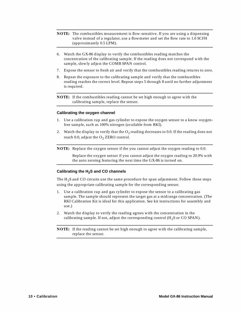
NOTE: The combustibles measurement is flow-sensitive. If you are using a dispensing valve instead of a regulator, use a flowmeter and set the flow rate to 1.0 SCFH (approximately 0.5 LPM).
6. Watch the GX-86 display to verify the combustibles reading matches the concentration of the calibrating sample. If the reading does not correspond with the sample, slowly adjust the COMB SPAN control.
7. Expose the sensor to fresh air and verify that the combustibles reading returns to zero.
8. Repeat the exposure to the calibrating sample and verify that the combustibles reading reaches the correct level. Repeat steps 5 through 8 until no further adjustment is required.
NOTE: If the combustibles reading cannot be set high enough to agree with the calibrating sample, replace the sensor.
Calibrating the oxygen channel
1. Use a calibration cup and gas cylinder to expose the oxygen sensor to a know oxygen-free sample, such as 100% nitrogen (available from RKI).
2. Watch the display to verify that the O2 reading decreases to 0.0. If the reading does not reach 0.0, adjust the O2 ZERO control.
NOTE: Replace the oxygen sensor if the you cannot adjust the oxygen reading to 0.0.
Replace the oxygen sensor if you cannot adjust the oxygen reading to 20.9% with the auto zeroing featuring the next time the GX-86 is turned on.
Calibrating the H2S and CO channels
The H2S and CO circuits use the same procedure for span adjustment. Follow these steps using the appropriate calibrating sample for the corresponding sensor.
1. Use a calibration cup and gas cylinder to expose the sensor to a calibrating gas sample. The sample should represent the target gas at a midrange concentration. (The RKI Calibration Kit is ideal for this application. See kit instructions for assembly and use.)
2. Watch the display to verify the reading agrees with the concentration in the calibrating sample. If not, adjust the corresponding control (H2S or CO SPAN).
NOTE: If the reading cannot be set high enough to agree with the calibrating sample, replace the sensor.
Model GX-86 Instruction Manual Calibration • 11
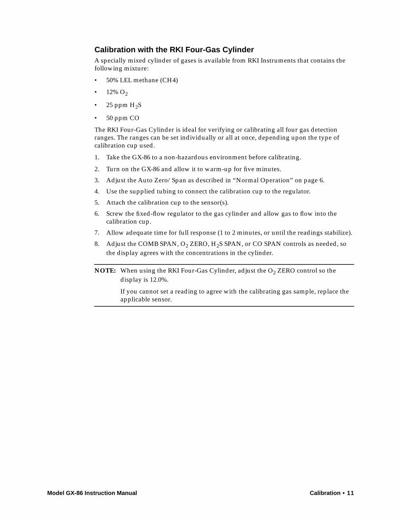
Calibration with the RKI Four-Gas CylinderA specially mixed cylinder of gases is available from RKI Instruments that contains the following mixture:
• 50% LEL methane (CH4)
• 12% O2
• 25 ppm H2S
• 50 ppm CO
The RKI Four-Gas Cylinder is ideal for verifying or calibrating all four gas detection ranges. The ranges can be set individually or all at once, depending upon the type of calibration cup used.
1. Take the GX-86 to a non-hazardous environment before calibrating.
2. Turn on the GX-86 and allow it to warm-up for five minutes.
3. Adjust the Auto Zero/Span as described in “Normal Operation” on page 6.
4. Use the supplied tubing to connect the calibration cup to the regulator.
5. Attach the calibration cup to the sensor(s).
6. Screw the fixed-flow regulator to the gas cylinder and allow gas to flow into the calibration cup.
7. Allow adequate time for full response (1 to 2 minutes, or until the readings stabilize).
8. Adjust the COMB SPAN, O2 ZERO, H2S SPAN, or CO SPAN controls as needed, so the display agrees with the concentrations in the cylinder.
NOTE: When using the RKI Four-Gas Cylinder, adjust the O2 ZERO control so the display is 12.0%.
If you cannot set a reading to agree with the calibrating gas sample, replace the applicable sensor.

12 • Maintenance Model GX-86 Instruction Manual
Maintenance
Batteries1. Check the battery voltage periodically by pressing the BATT button. Replace the
batteries before the voltage drops to the operational limit (see “Alarms” on page 7).
WARNING: Take the GX-86 to a non-hazardous location before replacing the batteries.
2. To replace the batteries, slide the battery compartment cover off the instrument case. Remove the batteries and verify that the battery compartment and electrical contacts are clean. If necessary, use a soft wire brush to gently clean the compartment and contacts. Insert fresh batteries (alkaline or fully-charged Ni-Cd) according to the polarity (+/-) markings, then replace the cover.
3. Bias Current Discharge
The batteries continuously supply a small current to maintain the H2S and CO sensors, even when the GX-86 is off (see Sensor Maintenance). This current drain is minimal but will result in a normal discharge of the batteries over a period of several weeks.
NOTE: If the batteries are fully discharged before replacement, allow up to 1/2 hour for the H2S and CO circuits to show a normal response.
CO FilterCO sensors are equipped with an activated carbon filter that removes H2S and most hydrocarbons to limit interference with the CO measurement.
To install the filter, slip it over the face of the CO sensor. Make sure the filter fits snugly and is seated properly. Replace the filter when CO readings become suspect (for example, the CO circuit calibrates properly but shows response in a known CO-free environment).
Sensor MaintenanceElectrochemical sensors (O2, H2S, CO) gradually deteriorate, regardless of use, and require periodic replacement. Combustibles sensor life is generally related to usage, but certain environmental factors may affect duration.
The GX-86 sensors are easy to replace, but only the combustibles sensor contains user-serviceable components. If a sensor requires replacement, call RKI or your local distributor. All sensors are warranted usable for one year from the date of shipment. Sensors that fail within the warranty period will be replaced at no charge.
Combustibles sensor
Replace the combustibles sensor or filaments when:
• the combustibles circuit cannot be calibrated correctly
• the COMB (%LEL) display does not show 0 immediately after the start-up sequence, and it cannot be set to zero by the Auto Zero command

Model GX-86 Instruction Manual Maintenance • 13
O2 sensor
Replace the O2 sensor when:
• the O2 circuit cannot be set to 0.0 on an oxygen-free sample
• the OXY (O2) display does not show 20.9% immediately after the start-up sequence and after the Auto Zero command
• the O2 reading tends to drift with instrument position
H2S and CO sensors
Replace the sensor when:
• the detection circuit cannot be calibrated correctly
• the display does not show 00 for H2S or 000 for CO immediately after the start-up sequence and cannot be set to zero by the Auto Zero command
NOTE: Allow up to 1/2 hour after the H2S or CO sensors have been replaced to show a normal response, then calibrate.
Sensor Replacement1. Place the GX-86 in a non-hazardous area.
2. Verify that the GX-86 is turned off, then remove it from the carrying case.
3. Press in the cover latch and slide the sensor cover down and away from the instrument case.
4. Open the spring clips, then unplug the sensor block (pull straight out).
5. Press the sensor down and turn counter-clockwise, then pull the sensor out of the block.
6. Insert the replacement sensor into the block and turn clockwise. Make sure you use the correct socket for the sensor type; sensors are not interchangeable between sockets.
7. Reinstall the sensor block and cover.
8. Start up the GX-86 and verify operation as described in “Start-up” on page 5.
9. Calibrate the replacement sensor as described in “Calibration” on page 9.
14 • Accessories Model GX-86 Instruction Manual
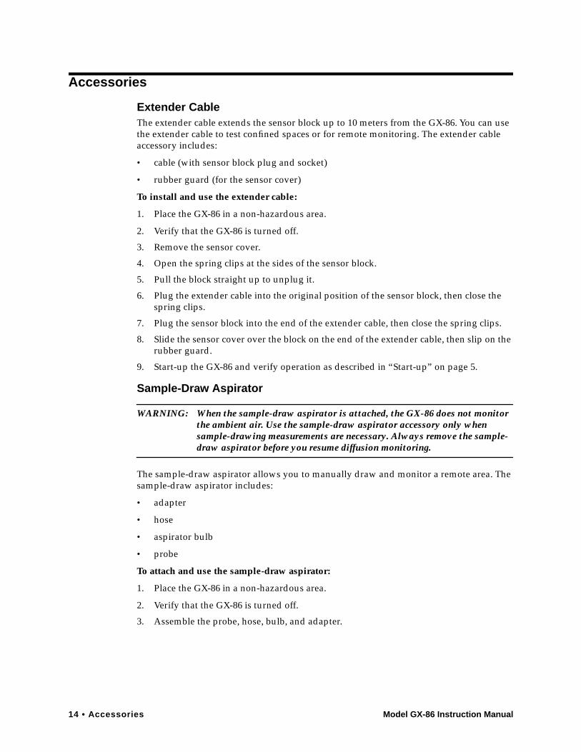
Accessories
Extender CableThe extender cable extends the sensor block up to 10 meters from the GX-86. You can use the extender cable to test confined spaces or for remote monitoring. The extender cable accessory includes:
• cable (with sensor block plug and socket)
• rubber guard (for the sensor cover)
To install and use the extender cable:
1. Place the GX-86 in a non-hazardous area.
2. Verify that the GX-86 is turned off.
3. Remove the sensor cover.
4. Open the spring clips at the sides of the sensor block.
5. Pull the block straight up to unplug it.
6. Plug the extender cable into the original position of the sensor block, then close the spring clips.
7. Plug the sensor block into the end of the extender cable, then close the spring clips.
8. Slide the sensor cover over the block on the end of the extender cable, then slip on the rubber guard.
9. Start-up the GX-86 and verify operation as described in “Start-up” on page 5.
Sample-Draw Aspirator
WARNING: When the sample-draw aspirator is attached, the GX-86 does not monitor the ambient air. Use the sample-draw aspirator accessory only when sample-drawing measurements are necessary. Always remove the sample-draw aspirator before you resume diffusion monitoring.
The sample-draw aspirator allows you to manually draw and monitor a remote area. The sample-draw aspirator includes:
• adapter
• hose
• aspirator bulb
• probe
To attach and use the sample-draw aspirator:
1. Place the GX-86 in a non-hazardous area.
2. Verify that the GX-86 is turned off.
3. Assemble the probe, hose, bulb, and adapter.
Model GX-86 Instruction Manual Accessories • 15
4. With the vinyl case on the GX-86, slide the adapter into place over the sensor cover.
5. Start-up the GX-86 and verify operation as described in “Start-up” on page 5.
CAUTION: Do not place the probe tip in liquid or other materials that could be drawn into the sample-draw aspirator or the GX-86.
6. Place the probe tip in the location you want to monitor, then squeeze the aspirator bulb several times at a moderate pace. Observe the display for changes in the readings.
Sample-Draw Pump
WARNING: When the sample-draw pump is attached, the pump must be turned on for the GX-86 to detect the target gases. The GX-86 may respond slower to changes in the ambient air with the sample-draw pump attached.
Use the sample-draw aspirator accessory only when sample-drawing measurements are necessary. Always remove the sample-draw pump before you resume diffusion monitoring.
The sample-draw pump allows you to continuously draw and monitor a remote area. The sample-draw pump includes:
• hose
• probe
• pump (powered by two AA-size batteries)
NOTE: The sample-draw pump’s batteries have a life span of approximately 10 hours of normal operation. The low flow alarm sounds when the batteries are too low to operate the pump. Always replace the batteries in a non-hazardous environment.
To attach and use the sample-draw pump:
1. Place the GX-86 in a non-hazardous area.
2. Verify that the GX-86 is turned off.
3. Assemble the pump, probe, and hose.
4. Remove the GX-86’s sensor cover, then slide the pump into place.
5. Verify that the rubber sensor chamber is in place and the pump housing is firmly seated and secured by the clips.
6. Start-up the GX-86, turn on the pump, and verify operation as described in “Start-up” on page 5.
CAUTION: Do not place the probe tip in liquid or other materials that could be drawn into the sample-draw pump or the GX-86.
7. Place the probe tip in the location you want to monitor. Observe the display for changes in the readings. If the pump’s sample system is blocked, the low flow alarm sounds.

16 • Appendix A: Parts List Model GX-86 Instruction Manual
Appendix A: Parts List
Table 5: GX-86 Parts List
Part Number Description
21-1070RK Battery cover (with retaining strap)
33-7101RK Filter (charcoal)
33-7104RK Filter retainer
61-0220RK Combustible gas sensor
65-1051RK Oxygen sensor
65-2003RK Carbon monoxide sensor
65-2023RK Sulfur dioxide sensor
65-2033RK Hydrogen sulfide sensor
71-0001RK Model GX-86 Instruction Manual
Model GX-86 Instruction Manual Appendix B: RKI Model GX-86 Relative Response Chart • 17
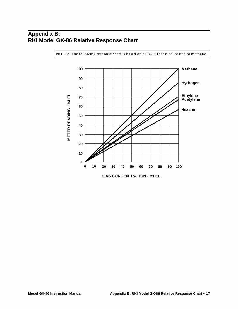
Appendix B:RKI Model GX-86 Relative Response Chart
NOTE: The following response chart is based on a GX-86 that is calibrated to methane.
0 10 20 30 40 50 60 70 80 90 1000
10
20
30
40
50
60
70
80
90
100
GAS CONCENTRATION - %LEL
ME
TE
R R
EA
DIN
G -
%L
EL
Methane
Hydrogen
EthyleneAcetylene
Hexane

18 • Appendix B: RKI Model GX-86 Relative Response Chart Model GX-86 Instruction Manual