gusev crater: wind-related features and processes observed by the mars exploration rover spirit
TRANSCRIPT

Gusev crater: Wind-related features and processes observed by the
Mars Exploration Rover Spirit
Ronald Greeley,1 R. E. Arvidson,2 P. W. Barlett,3 Diana Blaney,4 N. A. Cabrol,5
P. R. Christensen,1 R. L. Fergason,1 M. P. Golombek,4 G. A. Landis,6 M. T. Lemmon,7
S. M. McLennan,8 J. N. Maki,4 Timothy Michaels,9 J. E. Moersch,10 L. D. V. Neakrase,1
S. C. R. Rafkin,9 Lutz Richter,11 S. W. Squyres,12 P. A. de Souza Jr.,13 R. J. Sullivan,12
S. D. Thompson,1 and P. L. Whelley1
Received 11 May 2005; revised 23 September 2005; accepted 5 October 2005; published 6 January 2006.
[1] Wind-related features observed by the rover Spirit in Gusev crater, Mars, includepatches of soil on the surface, some of which are organized into bed forms.Windblown grains include dust (inferred to be <3 mm in diameter), sands (up to a fewhundred mm in diameter), and granules (>2 mm in diameter). Microscopic Imager datashow the sands and granules to be rounded and relatively spherical, typical ofgrains transported long distances by the wind. The interior of bed forms exposed byrover operations suggests the infiltration of dust among the grains, indicating that thesesands are not currently experiencing saltation. Orientations of 1520 features (such asbed forms and ventifacts) along Spirit’s traverse from the landing site (theColumbia Memorial Station) to West Spur in the Columbia Hills suggest primaryformative winds from the north-northwest, which correlate with measurements offeatures seen in orbiter images and is consistent with afternoon winds predicted byatmospheric models. A secondary wind from the southeast is also suggested, whichcorrelates with predictions for nighttime/early morning winds. Wind abrasion isindicated by ventifacts in the form of facets and grooves cut into rocks, theorientations of which also indicate prevailing winds from the north-northwest.Orientations of many aeolian features in the West Spur area, however, have morescatter than elsewhere along the traverse, which is attributed to the influence of localtopography on the patterns of wind. Active dust devils observed on the floor of Gusevfrom the Columbia Hills demonstrate that dust is currently mobile. Sequential imagesof some dust devils show movement as rapid as 3.8 m/s, consistent with windvelocities predicted by atmospheric models for the afternoon, when most of the dustdevils were observed. Sands accumulated on the rover deck in the same period suggestthat some sands in the Columbia Hills experience active saltation. ‘‘Two-toned’’rocks having a light band coating at their bases are considered to represent partialburial by soils and subsequent exposure, while ‘‘perched’’ rocks could representmaterials lowered onto other rocks by deflation of supporting soils. Measurements ofthe heights of the light bands and the perched rocks range from <1 cm to 27 cm,indicating local deflation by as much as 27 cm.
Citation: Greeley, R., et al. (2006), Gusev crater: Wind-related features and processes observed by the Mars Exploration Rover
Spirit, J. Geophys. Res., 111, E02S09, doi:10.1029/2005JE002491.
JOURNAL OF GEOPHYSICAL RESEARCH, VOL. 111, E02S09, doi:10.1029/2005JE002491, 2006
1Department of Geological Sciences, Arizona State University, Tempe,Arizona, USA.
2Earth and Planetary Sciences, Washington University, St. Louis,Missouri, USA.
3Honeybee Robotics, New York, New York, USA.4Jet Propulsion Laboratory, California Institute of Technology,
Pasadena, California, USA.5NASA Ames Research Center, Moffett Field, California, USA.6NASA Glenn Research Center, Cleveland, Ohio, USA.
Copyright 2006 by the American Geophysical Union.0148-0227/06/2005JE002491$09.00
E02S09
7Department of Atmospheric Sciences, Texas A&M University, CollegeStation, Texas, USA.
8Department of Geosciences, State University of New York at StonyBrook, Stony Brook, New York, USA.
9Southwest Research Institute, Boulder, Colorado, USA.10Department of Earth and Planetary Sciences, University of Tennessee,
Knoxville, Tennessee, USA.11Institut fur Raumsimulation, Deutschen Zentrum fur Luft- und
Raumfahrt, Cologne, Germany.12Department of Astronomy, Cornell University, Ithaca, New York,
USA.13CVRD Group, Vitoria, Brazil.
1 of 29

1. Introduction
[2] The floor of Gusev crater was selected as the landingsite for the Mars Exploration Rover Spirit [Arvidson et al.,2006]. Previous orbital analyses of this �160 km impactcrater have shown a complex geologic history that includespotential modification by mass wasting, fluvial activity,volcanism, and extensive aeolian (i.e., wind) processes[Kuzmin et al., 2000; Cabrol et al., 2003; Golombek etal., 2003, 2005; Greeley et al., 2003, 2004, 2005b].[3] In this report we document wind-related features
observed in the operational area of Spirit from the time oflanding on the first sol through sol 312 (3 January 2004through 18 November 2004; this corresponds to Ls 327.7�to 116.8�, or southern summer to southern winter). Wediscuss observations at the landing site, designated theColumbia Memorial Station (CMS) [Squyres et al., 2004]and along the �4 km traverse into the western flank of theColumbia Hills, called West Spur (Figure 1). We alsodiscuss observations of active aeolian processes postsol312 and the relationships of the observed aeolian surfacefeatures to those seen from orbit and to wind vectorspredicted by models of the atmosphere. Following thegeological convention, our wind directions are given inazimuths toward which the wind blows.[4] Various wind-related features and their dimensions
can be identified from the surface observations (Figures 2and 3). These include bed forms (such as ripples), driftdeposits associated with rocks, erosional and abraded fea-tures such as ventifacts, and features such as ‘‘perched’’rocks suggestive of wind deflation. In addition, fine-grainedmaterials (sand and dust) are analyzed in bed forms and aspatches on the surface. We use the term ‘‘soil’’ for thesematerials, following the convention of Squyres et al. [2004]for unconsolidated grains on or near the surface.[5] We first discuss the analytical approach and data sets
used for the study, then describe the wind-related featuresseen from the surface by Spirit and from orbit over the roveroperations area. We then discuss the wind regime derivedfrom the observations and as modeled, for comparisons withthe surface features. Finally, we discuss the implications ofthe results for the geology of Gusev crater, and outline someof the key problems that remain to be resolved.
2. Analytical Approach
[6] Images and other Spirit data relevant for aeolianfeatures were analyzed for the types and occurrences offeatures as functions of terrain in five zones along thetraverse (Figure 1). As described by Grant et al. [2004],the bedrock geology of the floor of Gusev crater appears toconsist of basaltic rocks [McSween et al., 2004] which wereprobably emplaced as very fluid lava flows �3.5 Gy ago[Greeley et al., 2005a], thus establishing an older age limitfor the surficial geology, including aeolian features.[7] Zone 1 (sols 1 through 61, Ls 327.7–360.0) includes
the immediate landing site, CMS, and the traverse to theapproximate edge of the ejecta blanket from Bonnevillecrater. This zone lies within a relatively dark linear windstreak seen on the surface from orbit that is inferred to bethe track left by the passage of a dust devil [Greeley et al.,2004]. Zone 2 (sols 62 through 109, Ls 0.5–23.8) is on the
ejecta deposits from Bonneville and Missoula craters. Itextends from the edge of zone 1 to the rim of Bonnevillecrater, then down the outbound traverse to the outer south-east edge of the ejecta from Missoula crater. This zone iswithin bright ejecta deposits, as seen from orbit. Zone 3(sols 110 through 155, Ls 24.2–45.2) is from the end ofzone 2 across the plains to West Spur at the base of theColumbia Hills. This zone consists primarily of plainsmaterials, but also includes some ejecta from small craters.Zone 4 (sols 156 through 193, Ls 45.7–62.5) is thetransitional area between the plains and West Spur. Itincludes a shallow moat-like area at the base of the hills,as detected on rover-derived topography [Li et al., 2005].Zone 5 (sols 194 through 312, Ls 62.9–116.8) is thetraverse up West Spur and along the connecting ridge tothe main Columbia Hills complex. Although most of therocks on the West Spur are loose fragments, a few bedrockexposures were encountered.[8] As summarized by Arvidson et al. [2006], the Co-
lumbia Hills have a relief of about 120 m over a lateraldistance of 2–3 km. Observations from Spirit indicate thatthe hills are composed of granular rocks that are layered,with layers tending to be conformable with topography[Squyres et al., 2006]. The rocks appear to be poorly sortedand composed of pyroxene, hematite, magnetite, and basal-tic glass. Some of the rocks exhibit evidence for goethite.Most of the rocks encountered are ‘‘float’’ underlain andsurrounded by soils, although some bedrock has also beenencountered. Enhanced values of sulfur, halides, and, insome cases, phosporus, relative to the plains olivine-bearingbasalts argue for aqueous alteration of the hills rocks. Soilsin the hills have textures, compositions, and mineralsessentially identical to the basaltic soils found in the plains.These similarities argue that winds have homogenized thesoils to first order over distances that exceed the �4 kmtraverse covered by Spirit. Moreover, thin dust depositscover soils and rocks in the hills in much the same manneras was found in the plains.
2.1. Image Analysis
[9] Images from the Pancam [Bell et al., 2003], Nav-cam, and Hazcam [Maki et al., 2003] were searched forfeatures indicative of wind processes. Each feature wasclassified by type (e.g., ripples) and measurements takenof specific parameters such as ripple length and azimuth.In addition, Golombek et al. [2005] obtained counts ofrocks 0.05 to 2 m in diameter for �70� sectors ofpanoramas within 10 m of the rover at the CMS, at theboundary of zones 1 and 2, and near the rim of Bonne-ville crater (zone 2). These data were used to deriveestimates of the aerodynamic roughness parameter, z0(Table 1). Higher values of z0 (due to larger and/or moredensely distributed rocks) indicate that a larger fraction ofwind shear stress will be absorbed by these roughnesselements, resulting in a smaller fraction of shear stressavailable to move loose grains on the surface between theroughness elements [Gillette and Stockton, 1989; Raupachet al., 1993; Nickling and McKenna Neuman, 1995]. Grainmovement could be retarded through these areas, leading togreater abundances of drifts associated with roughnesselements. This is evidenced by the increased frequency ofbed forms in zone 2 compared to zone 3.
E02S09 GREELEY ET AL.: GUSEV CRATER OBSERVED BY SPIRIT
2 of 29
E02S09
[10] The frequency distributions of aeolian featureswere normalized by surface area of the scenes imaged.Most of the Navcam and Hazcam images were taken inmiddle to late afternoon, so the illumination was generallyconsistent. However, the orientation of the rover withrespect to illumination was not consistent, a factor thatis particularly significant for the Hazcams, which arefixed to the rover body. Also, the Pancam frames werenot always taken at the same time of day. In addition, thePancam frames tended to be acquired with viewingtoward the southeast, giving a somewhat biased view ofthe northwest sides of rocks. The extent of soil patches(areas that lack organized bed forms, wind tails, rocks andbedrock) were determined using polar-projected Navcamimages; however, rocks smaller than �15 cm across wereoften difficult to discern and they are included in the soilpatch category.[11] Images from the Microscopic Imager (MI)
[Herkenhoff et al., 2003] were analyzed for soils onthe surface and in the subsurface where exposed by roverwheel operations [Herkenhoff et al., 2004]. Grain size
frequency distributions were determined from the MI framesand the longest and shortest axes of individual grainswere measured. We follow the Wentworth Grade Scale[Wentworth, 1922] for the classification and sizes of thegrains (Table 2). The MI images have a pixel scale of 31 mm/pixel [Herkenhoff et al., 2003] and in some high-qualityimages we can identify individual grains as small as 120 mmin diameter. However, for grain size distributions and shapes,only grains >200 mm in diameter (fine sands and larger)could be analyzed with confidence. As discussed previously[Arvidson et al., 2004], the texture of soils where compactedby the Mossbauer spectrometer plate suggests the presenceof very fine grains, inferred to be dust or weakly bonded dustaggregates. Martian dust in the atmosphere is considered tobe composed of particles �3 mm in diameter, based on theoptical properties [Lemmon et al., 2004].
2.2. Miniature Thermal Emission Spectrometer(MiniTES) Data
[12] The Miniature Thermal Emission Spectrometer(MiniTES) provides remote sensing information on the
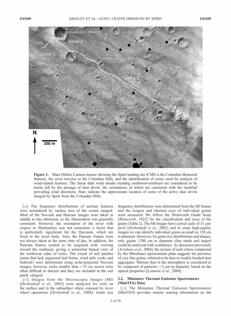
Figure 1. Mars Orbiter Camera mosaic showing the Spirit landing site (CMS is the Columbia MemorialStation), the rover traverse to the Columbia Hills, and the identification of zones used for analysis ofwind-related features. The linear dark wind streaks trending northwest-southeast are considered to betracks left by the passage of dust devils, the orientations of which are consistent with the modeledprevailing wind directions. Stars indicate the approximate location of some of the active dust devilsimaged by Spirit from the Columbia Hills.
E02S09 GREELEY ET AL.: GUSEV CRATER OBSERVED BY SPIRIT
3 of 29
E02S09

Figure 2
E02S09 GREELEY ET AL.: GUSEV CRATER OBSERVED BY SPIRIT
4 of 29
E02S09
mineralogy and physical properties of soils and rocks[Christensen et al., 2003], and is especially important forassessing materials that are not in the immediate vicinity ofthe rover. Thermal inertia data were derived from MiniTESmeasurements acquired at multiple times during the day.The measured radiance was converted to a target tempera-ture, which approximates the surface kinetic temperature.These temperatures were then used to determine the thermalinertia. Particle sizes were inferred using the techniquedescribed by Presley and Christensen [1997] and the resultswere compared to particle sizes measured directly in MIimages where available. When deriving particle sizes fromthermal inertia measurements, an atmospheric pressure of600 Pascals was used (Martian atmospheric pressure at�1.5 km, the elevation of the landing sites, and Ls 0� (fromSmith and Zuber [1998]) and combined bulk density andspecific heat of 1.0 � 106 J/m3 [Neugebauer et al., 1971].Initial thermal inertia results at Gusev were reported byChristensen et al. [2004a] and Golombek et al. [2005].Thermal inertia values given here differ slightly from thoseinitial results due to improvements in the MiniTES instru-ment calibration, the inclusion of Pancam dust opacitymeasurements as model input parameters, varying bothalbedo and inertia to fit diurnal temperature curves, andthe use of full diurnal temperature measurements rather thannighttime data only. These differences, however, do notsignificantly change the geologic interpretation.
2.3. Orbiter Data
[13] Mars Orbiter Camera (MOC) [Malin and Edgett,2001] images from Mars Global Surveyor (MGS) wereanalyzed to determine the orientations of wind-relatedfeatures in the general area of Spirit operations. All MOCNarrow Angle images taken from April 1999 to October2003 were analyzed for an area 20 by 20 km centered onCMS. All of the images analyzed were taken through a redequivalent filter (500–900 nm) and have resolutions of 1.4to 7.1 m/pixel. In addition, Thermal Emission ImagingSystem (THEMIS) [Christensen et al., 2004b] data fromMars Odyssey and High Resolution Stereo Camera (HRSC)[Neukum et al., 2004] images from Mars Express wereanalyzed to identify potential changes on the surface justbefore and during Spirit operations [Greeley et al., 2005b].
2.4. Atmospheric Modeling Predictions
[14] Results from two atmospheric models were used topredict wind patterns for comparisons with the aeolianfeatures. The NASA Ames Mars General Circulation Model(MGCM) simulates the mean atmosphere of Mars with astandard simulation grid spacing of 9.0� in longitude by7.5� in latitude [Pollack et al., 1990; Haberle et al., 1993].Thus the MGCM predicts wind patterns over large areas toprovide an assessment of the general wind regime. The
Mars Regional Atmospheric Modeling System (MRAMS)[Rafkin et al., 2001] is used to predict finer-scale winds, andwas used to model winds in Gusev crater in support of MERlanding site selection [Rafkin and Michaels, 2003] and forcomparison with surface features [Greeley et al., 2003].MRAMS is a nonhydrostatic, fully compressible mesoscaleatmospheric model, which employs ‘‘nested’’ grid cells forenhanced resolution over areas of interest. The model usesMGCM results for lateral boundary conditions, and surfacecharacteristics derived from MGS, including Mars OrbiterAltimeter (MOLA) 1/32� gridded topography, ThermalEmission Spectrometer thermal inertia [Putzig et al.,2005] and albedo at 1/20� and 1/8� resolution, respectively.
3. Observations From Spirit
[15] Pancam views (Figures 2a and 3a) from Spirit acrossthe floor of Gusev crater show a terrain dominated by loosebasaltic rocks, inferred to be ejecta from impact craters, setin a matrix of soils that have probably been emplaced byaeolian processes [Squyres et al., 2004; Grant et al., 2004].In this section we classify and describe the deposits ofwindblown materials and the rocks that appear to have beensubjected to aeolian processes.
3.1. Wind Depositional Features
[16] Deposits of windblown materials occur in organizedbed forms (such as ripples), drifts, wind tails, patches of soilon the surface, and as dust settled from the atmosphere,which typically forms a veneer on the tops of rocks and thesoils. Soil deposits and bed forms are more frequent on thefloors of impact craters, such as Bonneville, and withinshallow circular depressions, or ‘‘hollows,’’ that are inferredto be small, highly degraded impact craters partly filled withwindblown material (Figure 3a) [Grant et al., 2004, 2006;Golombek et al., 2006].3.1.1. Soils[17] In general, the soils consist of five components
(Figure 4): (1) bright dust, (2) a monolayer of coarse sandsand granules (0.5 to a few mm in diameter), (3) subangularlithic fragments several mm or larger in length, (4) acohesive crust as thick as several mm beneath the dustand coarse grains, and (5) dark soil (Figure 2g). Not all ofthese materials are present in all locations [Yen et al., 2005].[18] The bright dust deposits (Figure 2f) form a veneer
that is inferred to be thinner than a mm and to consist ofparticles a few mm in diameter that settled from theatmosphere. It has the same visible to near-IR spectralproperties as the material that settled on the rover deckand the material observed on tops of rocks. The monolayerof coarse grains, where present, forms a surface ‘‘armor’’(Figure 4b) considered to be a lag deposit of windblownmaterial that is probably transported in traction, or creep, by
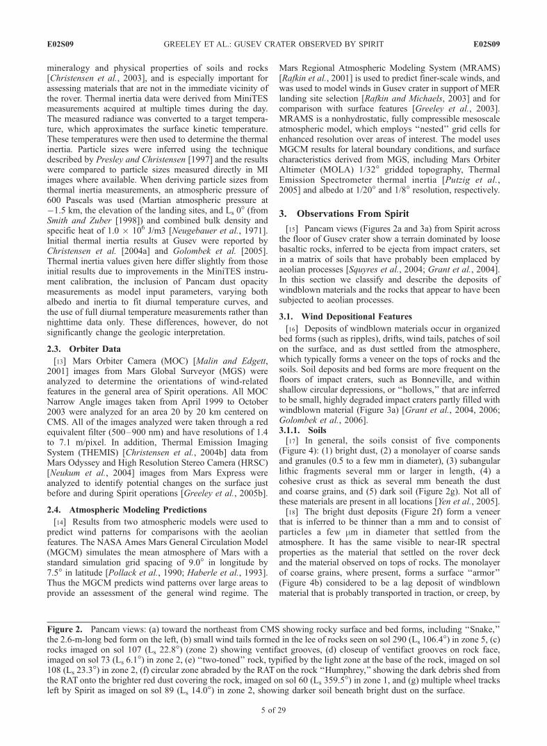
Figure 2. Pancam views: (a) toward the northeast from CMS showing rocky surface and bed forms, including ‘‘Snake,’’the 2.6-m-long bed form on the left, (b) small wind tails formed in the lee of rocks seen on sol 290 (Ls 106.4�) in zone 5, (c)rocks imaged on sol 107 (Ls 22.8�) (zone 2) showing ventifact grooves, (d) closeup of ventifact grooves on rock face,imaged on sol 73 (Ls 6.1�) in zone 2, (e) ‘‘two-toned’’ rock, typified by the light zone at the base of the rock, imaged on sol108 (Ls 23.3�) in zone 2, (f) circular zone abraded by the RAT on the rock ‘‘Humphrey,’’ showing the dark debris shed fromthe RAT onto the brighter red dust covering the rock, imaged on sol 60 (Ls 359.5�) in zone 1, and (g) multiple wheel tracksleft by Spirit as imaged on sol 89 (Ls 14.0�) in zone 2, showing darker soil beneath bright dust on the surface.
E02S09 GREELEY ET AL.: GUSEV CRATER OBSERVED BY SPIRIT
5 of 29
E02S09

Figure 3. Pancam views: (a) across a small ‘‘hollow’’ toward CMS (southeast) imaged on sol 69 (Ls
4.1�) in zone 2, showing accumulation of windblown sediments in the depression and as bed forms on therim (note wheel track across bed form), (b) the rock ‘‘Toad’’ in ‘‘Laguna Hollow,’’ imaged on sol 53 (Ls
355.9�) in zone 1, showing small ripples, (c) bed forms inferred to be ripples and very small wind tailsassociated with pebbles imaged on sol 56 (Ls 357.5�) in zone 1, (d) ventifact facets showing characteristicsharp crest where two facets meet, imaged on sol 99 (Ls 18.9�) in zone 2, (e) ventifact grooves that appearto be partly buried by soils, imaged on sol 87 (Ls 13.1�) in zone 2, and (f) ‘‘perched’’ rock on top of therock ‘‘Terrace,’’ imaged on sol 63 (Ls 1.0�) in zone 2.
E02S09 GREELEY ET AL.: GUSEV CRATER OBSERVED BY SPIRIT
6 of 29
E02S09

the impact of smaller saltating grains. The larger lithicfragments might also represent material that could bemoved in surface traction (Figure 4c). Some soils that havebeen disturbed by the rover wheels break into small slabs,or plates, a few mm thick and as large as 15 cm across(Figure 4d) (L. Richter et al., manuscript in preparation,2006). This behavior is interpreted to represent the presenceof a crust of cohesive material, either by cementation orelectrostatic bonding. Dark soils are found beneath thesurface material, wherever the rover wheels or the Instru-ment Deployment Device (IDD) operations have disturbedthem (Figures 2g and 4e).[19] Clastic materials such as sand are commonly
described on Earth on the basis of their size distributions,grain roundness, grain shape, and other parameters[Pettijohn et al., 1987]. Size distributions are typicallydetermined by sieving samples into size fractions and apply-ing statistical measures to the results. Particularly importantare the central tendency (such as the mean), maximum size,sorting (dispersion around the central tendency), and pres-ence of more than one central tendency, such as bimodality.These and other parameters provide information on thehistory of the deposits and the processes involved in theiremplacement. Although a complete sedimentary analysis ofsoils at Gusev cannot be made with available data, MI imagesprovide a surrogate for some of these parameters.[20] Some of the soils imaged by the MI have a bimodal
size distribution of coarse grains in a matrix of fine grainstoo small to be resolved by the MI, but inferred to be dust oraggregates of dust grains. MI images (Figures 5 and 6) weretaken of soils: (1) on two bed forms (Drifter and Arena),(2) nonorganized soil (Ramp Flats), and (3) the bed form,Serpent (where the surface was disrupted to expose thesubsurface materials). Drifter and Arena have a surfacemonolayer of coarse grains 1 to 2 mm in diameter thatappear to be well sorted (Figure 7). We suggest that thismonolayer represents a lag deposit that armors the surfaceof the bed form near the crest, similar to that observed bySharp [1963] in the Mojave Desert. The coarse clasts inRamp Flats range in size from 0.25 to >9 mm, and are verypoorly sorted. The size distribution revealed in the disturbedinterior of Serpent shows a bimodal (or trimodal, taking intoaccount the inferred dust) distribution centered at about1.4 mm and 0.35 mm. The coarser mode is represented byparticles of the coarse sand and granule armor, which areconsidered to have slid into the depression left by the roverleft front wheel. We suggest that this distribution reflects theoverall composition of the undisturbed bed form interior toinclude fine sand and infiltrated dust. Unfortunately, data donot allow the determination of the amounts of dust and finesand present in the bed form as a whole. However, thepresence of the infiltrated dust suggests that the particles inthe bed form do not currently experience saltation becausethe dust would have been ‘‘cleansed’’ from the sands in the
process. Furthermore, the coarse-grained armor of a mono-layer of particles covering the bed form exhibits signs ofinterparticle induration in the form of fracture lines wherethey have been disturbed by the rover, similar to crustsobserved in nonorganized soils (L. Richter et al., manuscriptin preparation, 2006). Thus the Serpent bed form is notconsidered to be currently active.[21] Shape is typified by measurements of the long, short,
and intermediate axes of the grains in an x, y, and zcoordinate system, and is used assess parameters such assphericity. Roundness is a parameter that refers to thecurvature of the corners of grains. Both shape and round-ness are commonly determined qualitatively in the fieldusing comparison charts. On the basis of the chart of Dutroet al. [1989], MI data enable these parameters to bedetermined for the coarse grains observed in Gusev soils.The coarse grains in the bed forms are rounded to wellrounded, and subprismoidal to spherical in shape. In com-bination with the high degree of sorting, these results aretypical for grains that have been transported some distance(i.e., not from local sources), during which the corners wereabraded and smoothed. In contrast, the coarse clastics inRamp Flats are discoidal, suggesting that they are locallyderived. Their roundness, however, shows that they havebeen abraded by a process that we suggest was the impact ofsaltating grains (i.e., ‘‘sand blasting’’) in the past.[22] MiniTES temperature measurements and Pancam
images provide additional information on the soils that werenot accessed directly by the rover. Initial results indicate thatthe thermal inertia increases from the CMS toward Bonne-ville crater, ranging from 150 ± 25 to 450 ± 75 J m�2 K�1
s�1/2 [Christensen et al., 2004a; Golombek et al., 2005],which probably reflects the increase in rocky ejecta towardthe crater rim. Some of the lowest thermal inertia materialwas found in the hollows (Figure 3a). For example, MiddleGround Hollow has a thermal inertia of 150 ± 28 J m�2 K�1
s�1/2 [Fergason et al., 2006] corresponding to fine sand(Table 2) [Presley and Christensen, 1997]. The MiniTESthermal inertias for the soils average 175 ± 25 J m�2 K�1
s�1/2 [Fergason et al., 2006] along the traverse from CMS
Table 1. Rock Distributions and Derived Aerodynamic Roughness, z0
Zone Name Area, m2Numberof Rocks Rock Coverage, % Largest Rock, m
AerodynamicRoughness, cm
1 Mission Success 57 1089 7 0.5 0.0042 Legacy 58 426 5 0.8 0.122 Bonneville 84 689 29 1.3 0.14
Table 2. Abbreviated Wentworth Grade Scale for Small Clastic
Particles Compared to ‘‘Dust’’ Diameters on Earth and Marsa
Diameter, mm Particle Diameter, mm
4–2 granule 4000–20002–1 very coarse sand 2000–10001–0.5 coarse sand 1000–5000.5–0.25 medium sand 500–2500.25–0.125 fine sand 250–1250.125–0.0625 very find sand 125–62.50.0625–0.004 silt 62.5–4<0.004 clay <4
aDust: Earth continental, 10–50 mm [Pye, 1987]; Earth intercontinental,mm < 10 [Pye, 1987]; Mars atmosphere, �3 mm [Lemmon et al., 2004].
E02S09 GREELEY ET AL.: GUSEV CRATER OBSERVED BY SPIRIT
7 of 29
E02S09

Figure 4
E02S09 GREELEY ET AL.: GUSEV CRATER OBSERVED BY SPIRIT
8 of 29
E02S09

to Bonneville crater. These values are consistent with thosecalculated from THEMIS (270 ± 40 to 330 ± 50 J m�2 K�1
s�1/2, average 306) and TES (315 ± 20 J m�2 K�1 s�1/2)data obtained from orbit [Golombek et al., 2005], suggest-ing a particle size of 500–3000 mm in soil patches[Christensen et al., 2004a].3.1.2. Bed Forms[23] Bed forms, such as ripples and dunes, are deposits of
sand and granule-size particles transported principally insaltation in flowing fluids and organized into regular pat-terns. Fluids can be wind, water, or dense mixtures ofparticles and gases, as in base surge deposits from volcaniceruptions or impact cratering events. The size, shape, andarrangements of bed forms, coupled with analyses of theparticles and internal bedding structures, provide insightinto the processes of formation, directions and distance oftransport, and the potential sources of the grains of whichthey are composed. Smaller bed forms, such as ripples,often reflect wind conditions strongly influenced by localtopography and can change patterns on timescales ofminutes, whereas larger bed forms, such as large dunes,are indicative of wind patterns over larger areas and longertimes. As reviewed by Pye and Tsoar [1990], windblowndunes require a supply of particles and winds of sufficientstrength to move them, and for sufficient wind durations tolead to an organized deposit. Once formed, existing dunesmay be remobilized as a consequence of increased windactivity and/or an influx of ‘‘fresh’’ particles, as duringheavy spring time runoff when fluvial systems transportmasses of clastic sediments. Consequently, dunes can beindicators of climate regime; for example, some dunes onEarth are not currently active and are considered to reflectpast climates [Livingstone and Warren, 1996]. The lengthsand orientations of bed form axes are defined by their crests,which for transverse features are orthogonal to the forma-tional wind direction. Under unidirectional winds, bedforms are asymmetric in cross section, with the steeperslope (‘‘slip face’’) on the downwind or leeward side. Thusthe identification of the steep side of bed forms enables thedetermination of the formational wind direction. However,bed forms subjected to ‘‘reversing’’ winds (winds with twoprevailing directions �180� apart) tend to have symmetriccross sections, leading to ambiguity in the interpretation ofthe formational wind direction.[24] In principle, dunes can be distinguished from ripples
by grain size distributions; dunes generally have finer grainsalong the crest in comparison to the area between dunes(i.e., the troughs), whereas ripples tend to have coarsergrains on their crest in comparison to the grains in thetroughs. MI images were obtained on the crest and inthe trough of only one bed form in Gusev, named Arena(Figure 5). The size distribution of grains measured on theMI images show that coarser grains occur on the crest
(Figure 7) and we conclude that Arena and most of thesimilar bed forms are ripples [Greeley et al., 2004]. Conse-quently, the orientations of these features may be moreindicative of local, topographically induced wind patternsthan of regional-scale patterns.[25] Bed forms are common in all five zones in Gusev,
but have a lower frequency in zone 3 (Figure 8). Their crestlengths range from a few cm to 16 m (Figures 3a, 3b, and 9)with most <2 m long. Although some occur in sets withwavelengths <0.5 m, most are found as isolated structuresset within soil patches. Some of the larger bed forms arethought to be small dunes or complex ripples that havemerged to form a larger mass, as shown in Figure 9.[26] Some features seen from orbit and in the distance
from Spirit have the appearance of dunes (i.e., could bedune forms). For example, Bonneville crater [Golombek etal., 2006, Figure 19] contains dune-like features on its floor.These large bed forms were not examined in situ but wereobserved by MiniTES remotely, and from these measure-ments a thermal inertia of 160 ± 35 to 200 ± 40 J m�2 K�1
s�1/2 was calculated [Fergason et al., 2006], correspondingto a particle size of �60 to 160 mm, or fine sand [Presleyand Christensen, 1997].[27] The orientations of bed form crests (Figure 10) in the
five zones are generally consistent and indicate formativewinds from either the north-northwest or south-southeast.Bed form cross sections were assessed qualitatively; of the387 features identified, �30 are considered to be asymmet-ric, �50 are symmetric, and the remainder have insufficientdata for determination. The orientations of the asymmetricbed forms suggests formative winds from the north-north-west. In addition, a topographic map was constructed forSerpent (Figure 6), which shows it to be slightly asymmetricand consistent with the formative winds from the northwest,although the steep downwind side of the bed form suggeststhe possibility of a reversing wind.[28] Several bed forms were crossed by the rover, which
left wheel depressions, revealing the dark soil component(Figures 2g and 4e). MI images of these areas suggest thepresence of sand and dust in the dark soil. In most cases thesurfaces of the bed forms did not fracture to form the plateyclods that would be indicative of a cohesive crust.[29] Bed forms viewed by MiniTES have thermal inertias
of 160 to 250 J m�2 K�1 s�1/2, suggesting particle sizes of60–400 mm in diameter, in agreement with particle sizesmeasured on MI images. MI data show a bimodal sizedistribution with modes centered on fine sand (0.1–0.3 mm)and coarse sand to granules (1–3 mm) [Herkenhoff et al.,2004].3.1.3. Drift Deposits (Wind Tails)[30] Deposits of windblown material occur around some
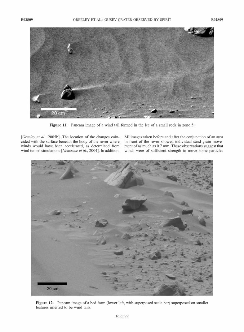
rocks as elongated triangular-shaped masses called windtails (Figure 2b), in which the apex is oriented in the
Figure 4. Various types of soils identified in Gusev crater: (a) Pancam image of bright dust coating the small rock named‘‘Route 66’’ taken on sol 100 (Ls 19.4�) in zone 2; the dark circular patterns show where the RAT brush has removed thedust revealing the underlying dark rock, (b) MI image of soil consisting of a mono-layer of coarse (�1 mm) grains taken onsol 52 (Ls 355.3�) in zone 1, (c) MI of soil containing irregularly shaped lithic fragments as large as 6 mm across, taken onsol 46 (Ls 352.3�) in zone 1 within a small ‘‘hollow,’’ (d) soil displaying fracture pattern (dark areas) suggestive of acohesive crust where the rover wheel disturbed the soil and a small rock, imaged by Pancam on sol 90 (Ls 14.6�) in zone 1,and (e) Pancam view taken on sol 130 (Ls 33.8�) in zone 2, where the rover tracks revealed dark soil.
E02S09 GREELEY ET AL.: GUSEV CRATER OBSERVED BY SPIRIT
9 of 29
E02S09

Figure 5. Soil characteristics for (a) the bed form named ‘‘Drifter’’ viewed in this Hazcam image inzone 1 (looking northeast) and the surface deposits seen in an MI image, (b) partly in shadow in upperleft, (c) Hazcam image toward the northeast of the bed form ‘‘Arena’’ and the location of (d) the MIimage taken on the crest of ‘‘Arena’’ and (e) the location of the MI image taken on the trough of‘‘Arena,’’ (f) Hazcam view of ‘‘Ramp Flats’’ and the location (cross) of the (g) MI image of the soils. Sunis from lower right in MI images.
E02S09 GREELEY ET AL.: GUSEV CRATER OBSERVED BY SPIRIT
10 of 29
E02S09

Figure 6. (a) Hazcam image of the bed form ‘‘Serpent’’ (zone 2), showing cross section (A–A), andoutline of the frame shown in Figure 6b. (b) Rover wheel operations ‘‘cut’’ into the side of the bed form,as imaged by the Pancam. Boundary of the (c) disturbed and (d) undisturbed (e) bed form and (f) thedebris in the disturbed part. (g) Topographic map of the bed form constructed from the Navcam stereoimages. (h) Cross section taken along A–A (see Figures 9d–9g for location) showing the inferred ‘‘slipface’’ at 32� on the south-southeast side; the near-symmetry of the bed form in cross section suggests thepresence of reversing winds.
E02S09 GREELEY ET AL.: GUSEV CRATER OBSERVED BY SPIRIT
11 of 29
E02S09

inferred downwind direction (Figure 11). Wind tails couldbe primary depositional features, similar to coppice dunesthat form on Earth around obstacles such as bushes, whichcan form a ‘‘dead’’ or ‘‘shadow’’ zone for wind. Alterna-tively, they could be erosional remnants of previously moreextensive deposits [Greeley et al., 2002]. In either case, theyrepresent a zone in the local wind regime that is protectedfrom wind erosion by the rock or obstacle with which theyare associated. Wind tails in Gusev range in length from<10 to �100 cm long and are most numerous in zone 3. Asshown in Figure 10, their common orientation along thetraverse indicates formative winds from the north-north-west, although in zone 2 the orientations suggest a bimodaldistribution of formative winds from the southeast. In zones4 and 5, the wind tails suggest a broader range of formativewind directions most likely resulting from the topographicinfluence of the Columbia Hills.[31] Figure 12 shows two sets of bed forms in zone 1 near
the landing site. The larger bed form (lower left corner)appears to be superposed on the wind tails, with the contactbeing relatively sharply defined. The orientation of the bedforms and the wind tails suggests winds from the right(southeast) in the image. This is in contrast to the formativewinds from the asymmetric bed forms which suggest thatthe bed forms passed over the wind tails, and that thematerials comprising the wind tail were sufficiently cohe-sive to be undisturbed. If this is correct, then the grainsmight be indurated, perhaps by cementation, suggesting thatthey are immobile and relatively older. Alternatively, thesmall wind tails could be erosional remnants left by thepassage of the larger bed forms.
3.2. Wind Erosional Features
3.2.1. Ventifacts[32] Wind eroded rocks (ventifacts) occur in two forms in
Gusev, as planar surfaces called facets (Figures 3d and 13c–13d) and as grooves (Figures 2d, 3e, 13a–13b, and 13e–13f). As reviewed by Greeley and Iversen [1985], ventifactsform primarily by abrasion of windblown particles. Facetsform orthogonal to the prevailing wind direction(s) respon-sible for ‘‘driving’’ the particles. Multiple facets can occur,
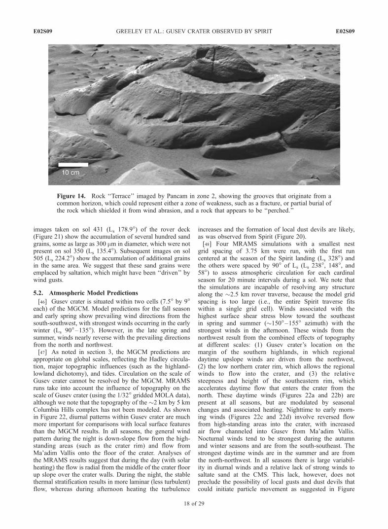
and the terms einkanter, zweikanter, and dreikanter (fromthe German for one-, two-, or three-edged rocks) are appliedto one, two, or three facets on any given rock (reviewed byLivingstone and Warren [1996]). Rocks with more than onefacet can result from multiple wind directions, shifting andoverturning of a rock to present a new surface to abrasion,or to complicated patterns of air flow and abrasion. Facets inGusev are as large as 1.2 m across. Most of the facetedrocks occur in zones 1, 2, and 5, with only 7 occurrencesin zones 3 and 4 combined. Orientations of the facets(Figure 10) in zones 1–3 are somewhat scattered, but tendto indicate formative winds from the north-northwest, withthe suggestion of a secondary formative wind from thesoutheast for zone 2. Formative winds for the facets in zone5 are relatively uniform from the northwest. Groovesconstitute more definitive ventifact features than the inferredwind-eroded facets. As shown in Figures 13b and 13f,grooves include wide, scalloped hollows as large as 20 cmacross on rocks, to narrow depressions. Following theconvention used by Bridges et al. [1999] for similar featuresseen at the Mars Pathfinder site, the orientations of theventifact grooves in Gusev suggest formative winds fromthe northwest for zones 1–3; as with the faceted rocks, thereare very few rocks that exhibit grooves in zone 4. Groovesin zone 5 suggest formative winds from the southwestwhich is attributed to the topographical influence of theColumbia Hills. A few rocks show ventifact grooves thatoriginate at a common level a few cm above the surface(Figure 14). This suggests that the rock contained a horizonthat facilitated groove formation, such as a fracture, or thatthe rock was partly buried and shielded from abrasion. Ifthis latter were the case, it would suggest that the surfacehas been ‘‘lowered’’ by 8 cm, perhaps by deflation of thesurrounding soils.3.2.2. Perched Rocks[33] In several places along the traverse, rocks are seen
that are ‘‘perched’’ on the tops of larger rocks (Figures 3fand 15). As discussed previously [Greeley et al., 2004],these are thought to represent remnants of mantling debristhat covered the area burying the underlying rocks. Throughsubsequent deflation, the fine materials were removed, and
Figure 7. Grain size distributions determined from MI images for the bed forms ‘‘Serpent,’’ ‘‘Drifter,’’and the crest of ‘‘Arena’’; grain size shown on log scale.
E02S09 GREELEY ET AL.: GUSEV CRATER OBSERVED BY SPIRIT
12 of 29
E02S09
the larger materials, including small rocks, were ‘‘lowered’’to the evolving surface. Some of these rocks are thought tohave then been left ‘‘perched’’ on other rocks. Alternatively,the ‘‘perched’’ rocks could simply represent in situ weath-ering along a plane of weakness. They might also be ejectafrom impact events, with the by chance emplacement on thetops of other rocks. The ‘‘perched’’ rocks are as high as
16 cm above the surrounding surface; if they representdeflation, then these values reflect the removal of materialby those minimum amounts.3.2.3. Two-Toned Rocks[34] Many of the rocks observed on the surface through-
out the traverse display a light-toned band at their base thatis in contrast to the rest of the rock (Figure 2e). Similarfeatures were observed at the Mars Pathfinder site wherethey were attributed to rocks that had been partly buried bysoil, and then exposed by deflation [Smith et al., 1997] or bytemporary partial burial due to a passing aeolian bed form[Greeley et al., 1999]. Similar explanations can be appliedto the two-toned rocks in Gusev crater. We suggest thatduring partial burial, the lower part of the rock may haveexperienced precipitation of minerals on the rock where itwas in contact with the soils, lightly cementing the observedfine soil in place. In situ measurements by Spirit (pre-RATbrush) were made on the light-toned parts of the rock,Mazatzal (Figure 13b) and were found to have chemistrywith elevated amounts of sulfur and chlorine similar to thesoils in Gusev, at the Mars Pathfinder site, and at the VikingLander sites [Gellert et al., 2004; Morris et al., 2004]. Post-RAT analysis shows a lack of the elevated sulfur andchlorine, but yield compositions similar to the dark basalticrocks in the area. Thus Gellert et al. [2004] suggested thatthe light-toned material was a coating that could be either alayer of dust or an alteration product. In either case, ifsaltating sands were abundant, one would expect the re-moval of the coating by sand impacts. Moreover, thegrooves on Mazatzal (Figure 13b), which are consideredto have been cut by sand abrasion, are light toned, suggest-ing that the coating was emplaced after the grooves werecut.[35] If the two-toned rocks indicate widespread deflation,
then they enable an estimate of the amount of deflation thathas occurred on the surfaces surrounding the rocks. About260 two-toned rocks were seen in sufficient detail todetermine the height of the horizon. Heights range from<0.1 to 27 cm above the surface (Figure 16), with anaverage of 3 cm and giving an indication of the possibledeflation. There is no trend in the heights of the horizon as afunction of zone or location along the traverse. However, asnoted by Greeley et al. [1999] at the Mars Pathfinder site,these heights do not necessarily mean that the entire surfaceon the floor of Gusev crater has been lowered by thisamount, because the same values could result from themigration of a bed form over the rocks, partly or completelyburying the rocks and leading to subsurface chemicalweathering.[36] Thus there is an inconsistency in the observations
that remains unresolved. The occurrence of the perchedrocks would tend to indicate a widespread mantle that hasbeen removed; in this case, one would expect all of therocks that were buried or partly buried should show the lightcoating. On the other hand, the observation that only somerocks have light-toned coatings suggests that the mantlingwas not contiguous, or of uniform thickness.
4. Features Seen From Orbit
[37] Numerous wind-related features are seen from orbitin the Spirit operations area. These include dune forms, dark
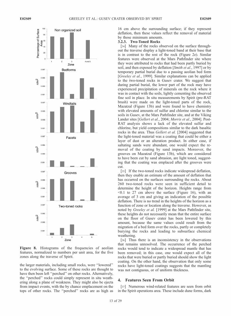
Figure 8. Histograms of the frequencies of aeolianfeatures, normalized to numbers per unit area, for the fivezones along the traverse of Spirit.
E02S09 GREELEY ET AL.: GUSEV CRATER OBSERVED BY SPIRIT
13 of 29
E02S09

wind streaks associated with topographical features, anddark linear streaks. Both types of wind streaks are albedopatterns that appear darker relative to the surroundingterrain (Figures 17d–17f). They are considered to representlocal erosion, in which bright material, such as dust, ismobilized by the wind, exposing a relatively darker sub-strate. Dark wind streaks associated with craters and othertopographic features, such as ridges, are clear indicators offormative wind directions (Figures 17d and 17e). As shownin Figures 18b and 18c, most of these appear to be from thenorthwest, especially at the CMS. Dark linear streaks areconsidered to be tracks left by the passage of dust devils[Grant and Schultz, 1987; Malin and Edgett, 2001]. In mostcases, it is not possible to determine the initial and terminalpoints on the linear streaks (Figure 17f) that would indicatethe wind direction, but it is assumed that the wind wasapproximately parallel to the general axis of the streak.[38] Dune forms are small linear to curvilinear positive
relief features and in Gusev they are found on the plains andon the floors of small craters. We note that similar smallfeatures are found in many regions of Mars, but there areinsufficient data to determine if they are dunes, largeripples, or some other type of bed form. Nonetheless, theyare considered to be accumulations of sand-size grainstransported principally in saltation. As with bed forms,transverse dunes have crests that are orthogonal to theprevailing formative winds. Consequently, the azimuths ofthe dune crest axes (Figure 18a), represent winds fromeither the north-northwest or the south-southeast. Unfortu-nately, it is not possible to identify points, or ‘‘horns’’(typical of barchan dunes) on the curvilinear dune formsthat might be indicative of wind direction. However, whenthe dark wind streak orientations are taken into account, theformative winds are interpreted to be approximately fromthe north-northwest.[39] THEMIS images taken over Gusev crater on
26 September 2003 (Ls 268�) before the landing of Spiritwere compared with HRSC images taken 16 January 2004(Ls 334�), shortly after the landing and about 2 weeks later
on 1 February 2004 (Ls 343�) [Greeley et al., 2005a, 2005b].In general, all types of dark wind streaks tended to ‘‘fade’’with time, apparently as a result of dust settling from theatmosphere. However, new dark features also developed inthis interval. The orientations of the new dark wind streakssuggest formative winds from the northwest, consistent withthe other features seen on the ground from orbit and with thewind directions inferred from features seen from Spirit.
5. Wind Regime
[40] The Athena payload has no provision for measuringwinds. However, there are some direct and indirect means tointerpret active winds during Spirit operations. These in-clude observations of changes on and around the rover thatare attributed to wind and comparisons with predictionsfrom models of the atmosphere.
5.1. Observations
[41] The MER Rock Abrasion Tool (RAT) [Gorevan etal., 2003] is used to brush or grind the surface of rocks. Inthe process, debris is ejected on radially symmetric trajec-tories, as determined by prelaunch laboratory tests. Devia-tions from a radially symmetric pattern can be attributed tofactors such as the shape of the surface surrounding theRAT site, or by the presence of wind during the operation,which might carry the debris in a down-wind direction(Figures 19a–19c). Initial results from Spirit showed thatRAT grinding on the rocks Humphrey (Ls 359�; 1100–1500LST) and Adirondack (Ls 345.8�; 1220–1520 LST) wereasymmetric, and were interpreted to result from winds fromthe northwest (Table 3) [Greeley et al., 2004]. Subsequently,additional rocks were abraded using the RAT, providingseven asymmetric patterns and four symmetric patterns. Onthe assumption that the asymmetric patterns result fromwinds at the time of RAT operations, most of the inferredwinds were from the northwest (Figure 19d). The exceptionis the pattern for the rock Wishstone, which suggests activewinds from the west.
Figure 9. Mosaic of two Navcam images taken on sol 111 (Ls 24.8�) in zone 3 showing multiple bedforms that have partly merged to form a larger mass; the shadowed area in the middle foreground isinferred to be the slip face for the mass, which would imply formative winds from the upper left towardthe lower right (toward the southeast).
E02S09 GREELEY ET AL.: GUSEV CRATER OBSERVED BY SPIRIT
14 of 29
E02S09
[42] For the most part, Spirit was seldom in one positionfor an extended time to monitor potential changes on thesurface. However, during solar conjunction from 5 to26 September 2004 (Ls 83.1� to 93.1�), the rover was in
one position (or ‘‘stand down’’) for 20 sols on West Spurwithin the Columbia Hills. Images taken before and afterthis period showed slight changes in color and albedo onthe surface that were attributed to movement of material
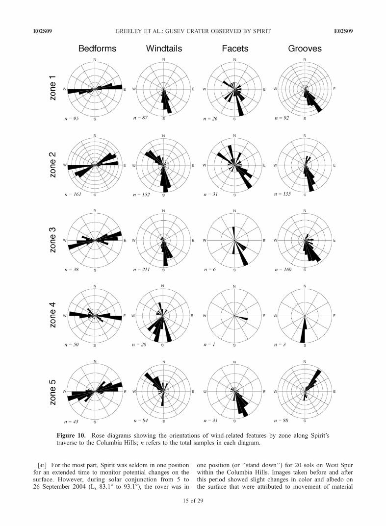
Figure 10. Rose diagrams showing the orientations of wind-related features by zone along Spirit’straverse to the Columbia Hills; n refers to the total samples in each diagram.
E02S09 GREELEY ET AL.: GUSEV CRATER OBSERVED BY SPIRIT
15 of 29
E02S09
[Greeley et al., 2005b]. The location of the changes coin-cided with the surface beneath the body of the rover wherewinds would have been accelerated, as determined fromwind tunnel simulations [Neakrase et al., 2004]. In addition,
MI images taken before and after the conjunction of an areain front of the rover showed individual sand grain move-ment of as much as 0.7 mm. These observations suggest thatwinds were of sufficient strength to move some particles
Figure 11. Pancam image of a wind tail formed in the lee of a small rock in zone 5.
Figure 12. Pancam image of a bed form (lower left, with superposed scale bar) superposed on smallerfeatures inferred to be wind tails.
E02S09 GREELEY ET AL.: GUSEV CRATER OBSERVED BY SPIRIT
16 of 29
E02S09

slightly, and the locations and orientations of the movementsuggest winds generally from the northwest.[43] Beginning on about sol 417 (Ls 170.9�), various
features were observed on the rover, which are attributableto active aeolian processes. Until this period, there was asteady decrease in output from the solar panels, which wasattributed to dust settling from the atmosphere. On sol 420(Ls 172.7�), the output increased markedly and is thought tohave resulted from clearing the dust from the solar panel bywind, perhaps by one or more wind gusts or dust devils.In the same period, dust accumulated on parts of thedeck where flow was obstructed, including a zone inthe ‘‘shadow’’ of the Pancam calibration target. From theorientation of the rover and the dust deposit, the windsappear to have been from the southeast toward an azimuthof 310�. In addition, a marked ‘‘blurring’’ of the Hazcam
images suggested that dust might have accumulated on thelenses initially on sol 417; subsequent images beginning onsol 420 suggest that the dust was removed.[44] Beginning on sol 421 (Ls 173.2�) active dust devils
(Figure 20) were observed on the floor of Gusev crater(Figure 1) in Hazcam, Navcam, and Pancam images fromSpirit’s perspective in the Columbia Hills. The dust devilsare as large as 40 m in diameter (consistent with the widthsof some of the dark linear wind streaks seen from orbit) andat least 158 m high. From the tilt (‘‘leaning’’ in thedownwind direction) of the column, the inferred directionsof motion were toward the south, north, and east; in onecase, sequential images indicate the rate of motion acrossthe plains was 2.5–3.8 m/s.[45] In addition to active dust devils, there is also indi-
cation of active sand saltation in the Columbia Hills. MI
Figure 13. Wind-eroded rocks, or ventifacts: (a) the rock ‘‘Adirondack’’ showing a flat, smooth face, orfacet, (b) the rock ‘‘Mazatzal’’ in zone 2 showing wind-eroded grooves, (c) small rocks showing facetsimaged by Pancam in zone 2, (d) a field of rocks in zone 4 showing facets, (e) rock in zone 1 showing afacet with grooves, and (f) Pancam image showing small grooves.
E02S09 GREELEY ET AL.: GUSEV CRATER OBSERVED BY SPIRIT
17 of 29
E02S09
images taken on sol 431 (Ls 178.9�) of the rover deck(Figure 21) show the accumulation of several hundred sandgrains, some as large as 300 mm in diameter, which were notpresent on sol 350 (Ls 135.4�). Subsequent images on sol505 (Ls 224.2�) show the accumulation of additional grainsin the same area. We suggest that these sand grains wereemplaced by saltation, which might have been ‘‘driven’’ bywind gusts.
5.2. Atmospheric Model Predictions
[46] Gusev crater is situated within two cells (7.5� by 9�each) of the MGCM. Model predictions for the fall seasonand early spring show prevailing wind directions from thesouth-southwest, with strongest winds occurring in the earlywinter (Ls 90�–135�). However, in the late spring andsummer, winds nearly reverse with the prevailing directionsfrom the north and northwest.[47] As noted in section 3, the MGCM predictions are
appropriate on global scales, reflecting the Hadley circula-tion, major topographic influences (such as the highland-lowland dichotomy), and tides. Circulation on the scale ofGusev crater cannot be resolved by the MGCM. MRAMSruns take into account the influence of topography on thescale of Gusev crater (using the 1/32� gridded MOLA data),although we note that the topography of the �2 km by 5 kmColumbia Hills complex has not been modeled. As shownin Figure 22, diurnal patterns within Gusev crater are muchmore important for comparisons with local surface featuresthan the MGCM results. In all seasons, the general windpattern during the night is down-slope flow from the high-standing areas (such as the crater rim) and flow fromMa’adim Vallis onto the floor of the crater. Analyses ofthe MRAMS results suggest that during the day (with solarheating) the flow is radial from the middle of the crater floorup slope over the crater walls. During the night, the stablethermal stratification results in more laminar (less turbulent)flow, whereas during afternoon heating the turbulence
increases and the formation of local dust devils are likely,as was observed from Spirit (Figure 20).[48] Four MRAMS simulations with a smallest nest
grid spacing of 3.75 km were run, with the first runcentered at the season of the Spirit landing (Ls 328�) andthe others were spaced by 90� of Ls (Ls 238�, 148�, and58�) to assess atmospheric circulation for each cardinalseason for 20 minute intervals during a sol. We note thatthe simulations are incapable of resolving any structurealong the �2.5 km rover traverse, because the model gridspacing is too large (i.e., the entire Spirit traverse fitswithin a single grid cell). Winds associated with thehighest surface shear stress blow toward the southeastin spring and summer (�150�–155� azimuth) with thestrongest winds in the afternoon. These winds from thenorthwest result from the combined effects of topographyat different scales: (1) Gusev crater’s location on themargin of the southern highlands, in which regionaldaytime upslope winds are driven from the northwest,(2) the low northern crater rim, which allows the regionalwinds to flow into the crater, and (3) the relativesteepness and height of the southeastern rim, whichaccelerates daytime flow that enters the crater from thenorth. These daytime winds (Figures 22a and 22b) arepresent at all seasons, but are modulated by seasonalchanges and associated heating. Nighttime to early morn-ing winds (Figures 22c and 22d) involve reversed flowfrom high-standing areas into the crater, with increasedair flow channeled into Gusev from Ma’adim Vallis.Nocturnal winds tend to be strongest during the autumnand winter seasons and are from the south-southeast. Thestrongest daytime winds are in the summer and are fromthe north-northwest. In all seasons there is large variabil-ity in diurnal winds and a relative lack of strong winds tosaltate sand at the CMS. This lack, however, does notpreclude the possibility of local gusts and dust devils thatcould initiate particle movement as suggested in Figure
Figure 14. Rock ‘‘Terrace’’ imaged by Pancam in zone 2, showing the grooves that originate from acommon horizon, which could represent either a zone of weakness, such as a fracture, or partial burial ofthe rock which shielded it from wind abrasion, and a rock that appears to be ‘‘perched.’’
E02S09 GREELEY ET AL.: GUSEV CRATER OBSERVED BY SPIRIT
18 of 29
E02S09

Figure 15. Various ‘‘perched’’ rocks (indicated by arrows): (a) Pancam image of rock in zone 2,(b) Pancam image of the rock ‘‘Gepetto’’ in zone 1, (c) Navcam image of rock in zone 2, (d) Pancamimage of rock in zone 2, and (e) Pancam image of rock in zone 2. Perched rocks are thought to representdeflation, or lowering of the surface by removal of material by the wind, leaving some rock in‘‘balanced’’ positions supported by one or more rocks.
E02S09 GREELEY ET AL.: GUSEV CRATER OBSERVED BY SPIRIT
19 of 29
E02S09

21. Such winds would be too small to be resolved in theMRAMS grid used here.
6. Discussion and Conclusions
[49] Aeolian activity requires a supply of loose particlesand sufficient winds to move them. Both sand and dust arepresent in Gusev crater, and observations from Spirit showthat dust and possibly sands are currently active in someareas. Active dust devils on the floor of Gusev wereobserved in images taken from about noon to 1500 LST,when heating of the surface is expected to generate unstableconditions. Sand-size grains were also observed to movesubcentimeter distances during the solar conjunction, al-though it is not clear that any grains were in saltation. Mostof the bed forms and soil patches that contain sand appear tohave intermixed dust, suggesting infiltration into sands.Thus it would appear that these sands are not currentlyexperiencing active saltation because such activity should‘‘purge’’ the finer grained dust from the deposit, setting itinto suspension and removal from the bed form. Further-more, an indurated armor of coarser grains is found onseveral of the observed bed forms. From the above obser-vations and assumptions, we conclude that most of thesands along the traverse are inactive, although the sandgrains on the rover deck that appeared on about sol 431 (Ls
178.9�) could indicate local saltation in the Columbia Hills.[50] Small particles amenable for wind transport are
produced by a wide variety of processes, including impactcratering, volcanism, and weathering of rocks. Salt weath-ering is a particularly effective mechanism for generatingfine grains in terrestrial deserts [Goudie et al., 1979]. In thisprocess, salts in solution enter microcracks and crystallize,exerting forces sufficient to break the rocks and largergrains into smaller fragments, particularly dust. Given the
possible salts detected from Spirit on rocks and in the soils[Gellert et al., 2006; Ming et al., 2006; Morris et al., 2006],salt weathering could be an important mechanism for thegeneration of dust on Mars and within Gusev crater. Theuniformity of dust compositions at the Viking lander, MarsPathfinder, Opportunity-Meridiani site, and Spirit-Gusevsites suggest that Martian dust becomes globally ‘‘homog-enized’’ after it is generated from various local sources. Thisis a reasonable assumption because dust can be carried tohigh altitudes in suspension where it is mixed and trans-ported long distances.[51] The numerous bed forms, such as ripples, signal the
presence of sand-size grains that were moved in saltation.Sand-size particles can occur as holocrystalline grains or asaggregates (small clods) of dust held together, perhaps bysalt cementation. MiniTES data argue for sand-sized basaltgrains to produce the signatures seen. Although someparticles imaged by the MI could be aggregates, thenumerous ventifacts indicate that the grains are holocrystal-line because laboratory experiments under Martian condi-tions show that aggregates cannot abrade rocks [Greeley etal., 1982]. Sands and granules could be derived locally, orthey could have been generated elsewhere and transportedinto Gusev crater by wind, water or as ejecta from impacts.Many of the Spirit images show granules and coarser clastsat the bases of rocks where they form apparent ‘‘lag’’deposits, and the spectra of the particles appear similar tothose of the rocks. This suggests that some rocks have beenweathered in situ and ‘‘shed’’ debris that collects around therocks. Acceleration of winds and turbulence around therocks could remove the fine sands, leaving the coarsergrains behind as a lag deposit.[52] In order to evaluate the potential transport distance of
sands in saltation, laboratory simulations were run underMartian conditions to determine the number of impacts that
Figure 16. Height above the surface to the boundary between the lower light-toned part and the upperdark-toned part of ‘‘two-toned’’ rocks as a function of zone along Spirit’s traverse.
E02S09 GREELEY ET AL.: GUSEV CRATER OBSERVED BY SPIRIT
20 of 29
E02S09
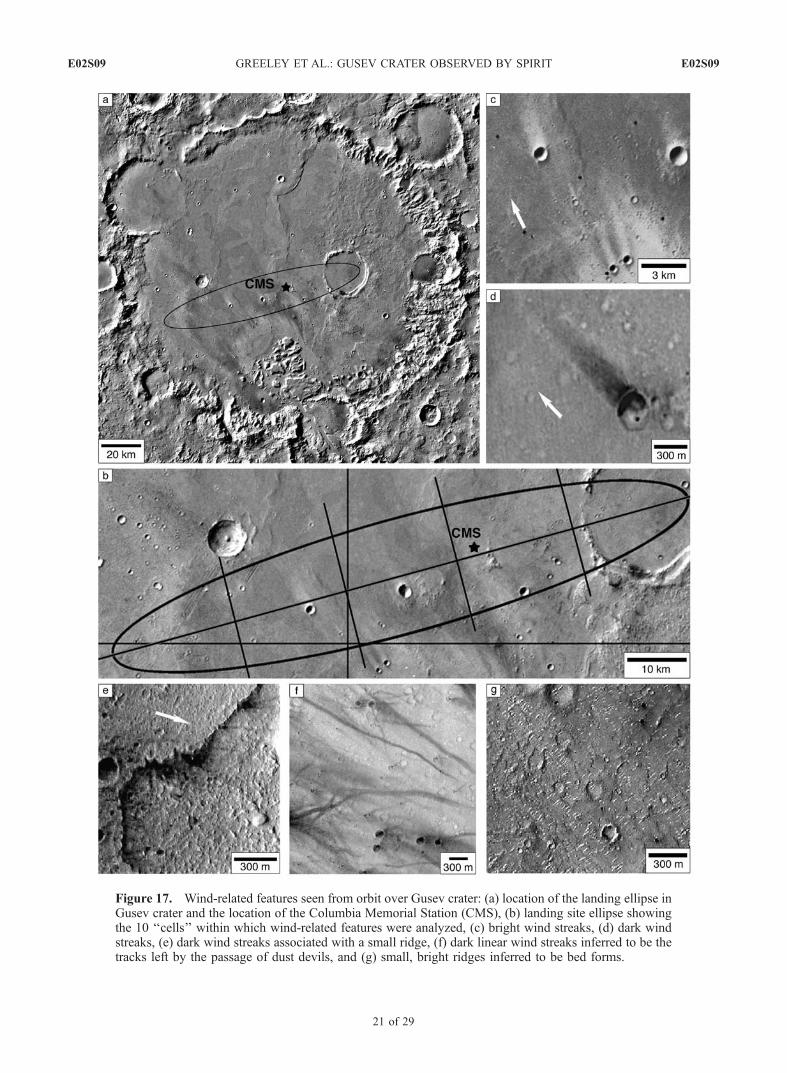
Figure 17. Wind-related features seen from orbit over Gusev crater: (a) location of the landing ellipse inGusev crater and the location of the Columbia Memorial Station (CMS), (b) landing site ellipse showingthe 10 ‘‘cells’’ within which wind-related features were analyzed, (c) bright wind streaks, (d) dark windstreaks, (e) dark wind streaks associated with a small ridge, (f) dark linear wind streaks inferred to be thetracks left by the passage of dust devils, and (g) small, bright ridges inferred to be bed forms.
E02S09 GREELEY ET AL.: GUSEV CRATER OBSERVED BY SPIRIT
21 of 29
E02S09

Figure 18. Rose diagrams of (a) dunes and (b) dark wind streaks within each cell in the landing ellipse.(c) Dark wind streaks and (d) dune axes for the dashed square cell centered on the Columbia MemorialStation (CMS).
E02S09 GREELEY ET AL.: GUSEV CRATER OBSERVED BY SPIRIT
22 of 29
E02S09

grains would survive before being comminuted into dust-size particles that would be removed by suspension (i.e., nolonger transported in saltation to develop bed forms).Results show that lithic and holocrystalline sand grainscan survive sustained saltation impacts, enabling transportdistances of 100s of km before being worn down into dustsizes [Greeley and Kraft, 2001]. Thus with the evidence forholocrystalline grains suggested by the presence of theventifacts, it is possible that at least some sands thatoriginated outside Gusev could have been transported intothe crater by wind. Sustained transport is also suggested bythe MI images that show well-rounded sand grains andgranules.[53] Comparisons of the frequencies and orientations of
wind-related features along Spirit’s traverse give insight intothe aeolian regime and surface processes in the area. Zone 3,the long traverse from Bonneville crater to the base of theColumbia Hills, has the maximum frequency of ‘‘perched’’
Figure 19. Wind directions inferred from the patterns of cuttings from the RAT, showing the rock(a) ‘‘Humphrey,’’ (b) ‘‘Adirondack,’’ and (c) ‘‘Wooly Patch 1 and 2,’’ along with (d) the azimuths ofthese and other patterns.
Table 3. Wind Directions Inferred From RAT Patterns
ZoneRock Feature
NameSol
(Spirit)Ls,deg
Operation Time,LSTa
Inferred WindDirection,b deg
1 Adirondack 34 345.8 1220–1520 157Humphrey 59 359.0 1100–1500 149
2 Mazatzal 1 81 10.1 1100–1440 130Mazatzal 2 83 11.1 1140–1500 130
4 Pot of Gold 169 51.6 1130–1315 none5 Wooly Patch 1 195 63.4 1345–1530 none
Wooly Patch 2 198 64.8 1320–1530 159Clovis 216 72.8 1250–1520 none
Ebenezer 231 79.5 1220–1400 noneUchben 285 104.1 1320–1445 143
Wishstone 334 127.4 1225–1340 88aLST, local solar time.bAzimuth toward which wind blew.
E02S09 GREELEY ET AL.: GUSEV CRATER OBSERVED BY SPIRIT
23 of 29
E02S09

rocks and wind tails, and the maximum extent of soilpatches that are not organized into bed forms. We interpretthe ‘‘perched’’ rocks to represent net deflation, or lowering,of the surface. Similarly, the soil patches could be theremains of deposits that are stabilized, perhaps by cemen-tation, or material that has not yet been removed. If theseinterpretations are correct, then this area appears to haveexperienced deflation of up to �27 cm (at least locally), themaximum height to the boundary of the light-toned parts oftwo-toned rocks and the heights of the ‘‘perched’’ rocks.[54] The orientations of most of the wind-related features
seen from orbit and the ground suggest primary winds fromthe north-northwest blowing to the south-southeast, and asecondary wind from the southeast. The north-northwestdirection correlates well with the predictions for strongafternoon winds, particularly in the summer and spring.These winds are attributed to the influence of topographyand afternoon heating which result in turbulent flow upslope. However, the bed forms, such as the ripples, tend tobe symmetric, which suggests reverse flow, consistent withnighttime winds predicted to be down slope from the craterrim onto the floor of the crater.[55] The orientations and frequencies of aeolian features
in the West Spur region of the Columbia Hills (zone 5) andthe transition from the plains to the Hills (zone 4) appearsomewhat anomalous in comparison to the other zones. Forexample, the ventifact groove orientations suggest forma-tive winds from the south-southwest, orthogonal to the flowtrends of resulting features seen elsewhere, which does notcorrelate with MRAMS predictions for any season or timeof day. We suggest that local topography (not modeled byMRAMS) strongly influences both the direction and mag-nitude of the winds responsible for these aeolian features, asis commonly observed on Earth [e.g., Greeley et al., 2002;Bridges et al., 2004]. For example, winds moving up slopeare commonly accelerated, at least initially, by flow com-pression, leading to increased abrasion and formation ofventifacts [Bridges et al., 2004].[56] The orientations of the wind related features ob-
served by Spirit are much more consistent with the winddirections predicted by the atmospheric model than was
observed at the Mars Pathfinder (MPF) site. At MPF, twoprevailing winds were inferred [Greeley et al., 2000], onefrom the northeast that correlates with atmposheric modelpredictions and a second wind from the east southeast that isnot predicted for any current wind regime. The second windpattern was suggested by the orientation of ventifacts seenon the surface and wind-eroded rims of small craters seenfrom orbit, and was attributed to a paleowind regime. Nosuch pattern has been detected in Gusev crater in this study,but it must be noted that wind patterns in Gusev appear tobe strongly controlled by local topography.[57] In conclusion, aeolian processes involving both sand
and dust are currently active in some parts of Gusev crater.It is likely that such processes have taken place throughoutthe history of Mars, so long as small particles and windshave been present. Although there are uncertainties in thedetailed ages of the surfaces over which Spirit traversed,much of the floor of Gusev crater appears to be surfacedwith basaltic bedrock emplaced some 3.5 Gyr ago, whichwould place an upper boundary on the age of the surficialdeposits, including the aeolian features on the plains. TheColumbia Hills, however, are thought to be older than theplains. Moreover, the rocks appear to be more weatheredand are much softer than the plains basalts [Arvidson et al.,2006; C. Schroder et al., manuscript in preparation, 2006]which would make them more susceptible to abrasion bywindblown particles, and could lead to contributions ofparticles for wind transport.[58] Several key questions remain to be resolved with
regard to aeolian processes in Gusev crater.[59] 1. Dust devils are clearly frequent at certain times of
the year. What is their contribution to the total mass of dustinjected into the atmosphere in comparison to local andregional dust storms raised by non-dust-devil processes?[60] 2. Although there are indications that sand is active
in some areas, what portion of the sand deposits experiencesaltation annually?[61] 3. Do the light toned rocks and the ‘‘perched rocks’’
represent a widespread mantle that has been removed,presumably by wind deflation, or are they the result of thepassage of local bed forms?
Figure 20. Active dust devils on the floor of Gusev crater viewed from the Columbia Hills: (a) Navcamimage on sol 496 (Ls 218.4�) of a dust devil about 45 m in diameter and (b) Navcam image taken on sol489 (Ls 213.9�) of a dust devil 23 m in diameter; sequential images suggest apparent movement of 5.0–6.0 m/s across the floor.
E02S09 GREELEY ET AL.: GUSEV CRATER OBSERVED BY SPIRIT
24 of 29
E02S09
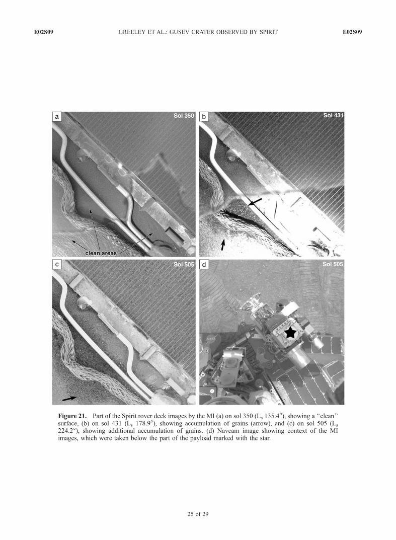
Figure 21. Part of the Spirit rover deck images by the MI (a) on sol 350 (Ls 135.4�), showing a ‘‘clean’’surface, (b) on sol 431 (Ls 178.9�), showing accumulation of grains (arrow), and (c) on sol 505 (Ls
224.2�), showing additional accumulation of grains. (d) Navcam image showing context of the MIimages, which were taken below the part of the payload marked with the star.
E02S09 GREELEY ET AL.: GUSEV CRATER OBSERVED BY SPIRIT
25 of 29
E02S09

Figure 22. Winds predicted by MRAMS for the southeastern part of Gusev crater for late afternoon inthe southern hemisphere (a) winter and (b) summer and for nighttime in (c) winter and (d) summer.Vectors represent azimuths toward which the winds blow, modeled at a height of 2 m above the surface.The cross marks the location of the Spirit landing and operations area. Wind vectors are superposed onMOLA topography, in which dark grey represents terrain at or higher than 1400 m above datum, andwhite (crater floor) is an elevation of �1900 m (below datum). This relief of 3.3 km generates substantialslope winds.
E02S09 GREELEY ET AL.: GUSEV CRATER OBSERVED BY SPIRIT
26 of 29
E02S09

Table A1. Image Identifications for Figures
Figure Sol(s) ID CameraView
Direction Feature Name Category
1 R13-03051, R13-01467, R20-01024 MOC-NA2a 6–10 2P127074636FFL0211P2215L2M3 Pancam NE Mission Success Pan bedforms2a 6–10 2P127090410FFL0211P2216L2M3 Pancam NE Mission Success Pan bedforms2a 6–10 2P127248269FFL0211P2216L2M2 Pancam NE Mission Success Pan bedforms2a 6–10 2P127247698FFL0211P2216L2M2 Pancam NE Mission Success Pan bedforms2b 290 2P152107547FFL8987P2542L4M1 Pancam windtails2c 107 2P135858857FFL3100P2554L2M1 Pancam Wallula Gap ventifact w/grooves2d 73 2P132838578SFL2000P2559L2M1 Pancam White Elephant ventifact w/grooves, close-up2e 108 2P135942564FFL3200P2392L2M1 Pancam Midfield Rock Survey two-tone2f 60 2P131696667FFL1159P2597L2M1 Pancam Humphrey RAT tail2g 89 2P134260621FFL2400P2533L2M1 Pancam tracks dark soil3a 69 2P132489576FFL1800P2289L2M1 Pancam SE Bonneville Pan hollow and bedforms3a 69 2P132490971FFL1800P2289L2M1 Pancam SE Bonneville Pan hollow and bedforms3a 69 2P132491257FFL1800P2289L2M1 Pancam SE Bonneville Pan hollow and bedforms3a 69 2P132485775FFL1800P2290L2M1 Pancam SE Bonneville Pan hollow and bedforms3a 69 2P132486067FFL1800P2290L2M1 Pancam SE Bonneville Pan hollow and bedforms3a 69 2P132489850FFL1800P2289L2M1 Pancam SE Bonneville Pan hollow and bedforms3a 69 2P132490691FFL1800P2289L2M1 Pancam SE Bonneville Pan hollow and bedforms3a 69 2P132491555FFL1800P2289L2M1 Pancam SE Bonneville Pan hollow and bedforms3a 69 2P132485659FFL1800P2290L2M1 Pancam SE Bonneville Pan hollow and bedforms3a 69 2P132483380FFL1800P2290L2M1 Pancam SE Bonneville Pan hollow and bedforms3b 53 2P131080679FFL1124P2573L2M1 Pancam Toad rock surrounded by windtails3c 56 2P131347008FFL1155P2584L2M1 Pancam Photometry sequence ripples (with small windtails)3d 99 2P135156114FFL2700P2542L2M1 Pancam Orel facet3e 87 2P134101174SFL2300P2460L2M1 Pancam Systematic Soil Survey grooves (into soil)3f 63 2P131954806SFL1300P2532L2M1 Pancam Orca Perched Rock and grooves4a 100 2N135241174EFF2702P1959L0M1 Navcam Route 66 Grooves4b 52 2M130974187EFF1100P2953M2F1 Micro-Imager Sugar T dusty grains4c 46 2M130463334EFF0900P2953M2F1 Micro-Imager Trout 1 poor sorted grains4d 90 2P134352572EFF2500P2514R1C1 Pancam Clast Survey broken slab4e 130 2P137912072ESF5000P2575L2C1 Pancam Don’t Tread on Me/Tracks dark soil5a 39 2F129834922EFF0500P1210L0M1 Front Hazcam Drifter bedform5b 39 2M129820929EFF0400P2943L0M1 Micro-Imager Squiggle bedform5c 40 2F129914137EFF0506P1210L0M1 Front Hazcam Arena bedform5d 41 2M130001298EFF0506P2943L0M2 Micro-Imager Crest - Arena bedform5e 41 2M130001885EFF0506P2943L0M1 Micro-Imager Trough - Arena bedform5f 44 2F130264571EFF0700P1120L0M1 Front Hazcam Flats plains5g 44 2M130267583EFF0700P2938L0M1 Micro-Imager Ramp Flats matrix supported clasts8 111 2N136235243EFF3600P1846L0M1 Navcam Navcam Pan bedform8 111 2N136234863EFF3600P1818L0M1 Navcam Navcam Pan bedform10a 71 2F132673311EFF18AAP1201L0M1 Front Hazcam Serpent bedform10b 72 2P132756681EFF1957P2352L2C1 Pancam Bear Paw - Serpent bedform10b 72 2P132756270EFF1957P2352L2C1 Pancam Bear Paw - Serpent bedform10c 73 2M132840805EFF2000P2937M2F1 Micro-Imager Serpent bedform10d 73 2M132841379EFF2000P2977M2F1 Micro-Imager Serpent bedform10e 73 2M132842058EFF2000P2977M2F1 Micro-Imager Serpent bedform10f 73 2M132842726EFF2000P2977M2F1 Micro-Imager Serpent bedform11 290 2P152107603FFL8987P2542L6M1 Pancam windtails12 41 2P129997661EFF0506P2534L2C1 Pancam Axe bedform superposed on windtails13a 16 2P127783908EFF0327P2370L7M1 Pancam Adirondack facet13b 76 2P133107031ESF2200P2567L3C1 Pancam Mazatzal facet and grooves13c 78 2P133290550FFL2232P2359L7M1 Pancam Bonneville Crater Pan facets13d 310 2P153892840FFL91C0P2426L7M1 Pancam Drive Direction Pan facets13e 58 2P131526768FFL1155P2437L7M1 Pancam Frontier grooved facet13f 88 2P134172259EFF2300P2450L4C1 Pancam Systematic Soil Survey grooved facet14 63 2P131954334SFL1300P2531R1M1 Pancam Orca grooved terrace rock15a 88 2P134183912FFL2400P2372L7M1 Pancam Drive Direction Perched Rock15b 41 2P129999373FFL0506P2531R2M1 Pancam Gepetto Perched Rock15c 65 2N132143228FFL1600P1835L0M1 Navcam Navcam Pan Perched Rock15d 108 2P135943222FFL3200P2392C2M1 Pancam Midfield Rock Survey Perched Rock15e 68 2P132404360FFL1800P2286L2M1 Pancam Bonneville Crater Pan Perched Rock17a 434S07 Viking Gusev Crater17b 434S07 Viking MER-A landing ellipse in Gusev17c 434S07 Viking Bright streaks bright streaks17d M10-03184 MOC-NA Dark Streak dark streak17e M07-00813 MOC-NA Dark Streaks - slope break dark streak17f R07-01606 MOC-NA Dark Streaks dark streak - few km N of LS17g M03-01042 MOC-NA Dunes transverse dunes19a 496 2N170391683SFLAAFQP1560L0M1 Navcam Navcam Dust Devil Movie dust devil19b 489 2N169770718SFLAAEOP1560L0M1 Navcam Navcam Dust Devil Movie dust devil20a 59 2P131613980SFL1155P2592L7M1 Pancam Humphrey RAT tail20b 35 2N129477093FFL0327P1635L0M1 Navcam Adirondack RAT tail
E02S09 GREELEY ET AL.: GUSEV CRATER OBSERVED BY SPIRIT
27 of 29
E02S09

[62] 4. Do the ventifacts represent current conditions, orwere they cut by processes in the past when conditions forwind abrasion might have been more favorable?[63] 5. There is an inconsistency in the orientations of the
facets and the grooves in the Columbia Hills. If both typesof features represent wind abrasion, why do they notindicate the same wind directions?[64] 6. What are the timescales of the features observed?
Although the dark linear wind streaks are shown to formcurrently, when did the dunes and ripples develop? Ifthey represent previous conditions, how long ago mightthey have formed and why was there a shift to currentconditions?[65] Some of these issues can be addressed with further
reduction and analysis of available data. In other cases, suchas determining the timescales of events not only in Gusevcrater but elsewhere on Mars, new data will need to beobtained.
Appendix A
[66] Most of the analysis of wind-related features is basedon imaging data from Spirit. Table A1 lists the keyparameters for the images used in the figures, and includesthe sol on which the image was taken, the camera system,the informal names applied by the MER team, and thecategory of feature illustrated.
[67] Acknowledgments. We thank Danny Foley, Michael Bentley,Stephanie Holaday, and Charles Hewett (all of ASU) for technical supportof this investigation. P. Whelley and S. D. Thompson were partly supportedby the NASA Space Grant Program at ASU. We thank Lori Fenton and ananonymous reviewer for extensive suggestions that enabled significantimprovements to the manuscript. This work was performed for the JetPropulsion Laboratory, California Institute of Technology, sponsored by theNational Aeronautics and Space Administration.
ReferencesArvidson, R. E., et al. (2004), Localization and physical properties experi-ments conducted by Spirit at Gusev crater, Science, 305, 821–824.
Arvidson, R. E., et al. (2006), Overview of the Spirit Mars ExplorationRover Mission to Gusev Crater: Landing site to Backstay Rock inthe Columbia Hills, J. Geophys. Res., 111, E02S01, doi:10.1029/2005JE002499.
Bell, J. F., III, et al. (2003), Mars Exploration Rover Athena PanoramicCamera (Pancam) investigation, J. Geophys. Res., 108(E12), 8063,doi:10.1029/2003JE002070.
Bridges, N. T., R. Greeley, A. F. C. Haldemann, K. E. Herkenhoff, M. Kraft,T. J. Parker, and A. W. Ward (1999), Ventifacts at the Pathfinder landingsite, J. Geophys. Res., 104, 8595–8615.
Bridges, N. T., J. E. Laity, R. Greeley, J. Phoreman, and E. E. Eddlemon(2004), Insights on rock abrasion and ventifact formation from laboratoryand field analog studies with applications to Mars, Planet. Space Sci.,521, 199–213.
Cabrol, N. A., et al. (2003), Exploring Gusev Crater with Spirit: Review ofscience objectives and testable hypotheses, J. Geophys. Res., 108(E12),8076, doi:10.1029/2002JE002026.
Christensen, P. R., et al. (2003), Miniature Thermal Emission Spectrometerfor the Mars Exploration Rovers, J. Geophys. Res., 108(E12), 8064,doi:10.1029/2003JE002117.
Christensen, P. R., et al. (2004a), Initial results from the Mini-TES experi-ment in Gusev crater from the Spirit Rover, Science, 305, 837–842.
Christensen, P. R., et al. (2004b), The thermal emission imaging system(THEMIS) for the Mars 2001 Odyssey mission, Space Sci. Rev., 110,85–130.
Dutro, J. T., R. V. Dietrich, and R. M. Foose (1989), AGI Data Sheets, Am.Geol. Inst., Alexandria, Va.
Fergason, R. L., P. R. Christensen, J. F. Bell III, M. P. Golombek,K. Herkenhoff, H. H. Kieffer, and R. Sullivan (2006), Physical propertiesof the Mars Exploration Rover landing sites as inferred from Mini-TESderived thermal inertia, J. Geophys. Res., doi:10.1029/2005JE002583, inpress.
Gellert, R., et al. (2004), Chemistry of rocks and soils in Gusev crater fromthe Alpha Particle X-ray Spectrometer, Science, 305, 829–832.
Gellert, R., et al. (2006), The Alpha Particle X-Ray Spectrometer (APXS):Results from Gusev crater and calibration report, J. Geophys. Res.,doi:10.1029/2005JE002555, in press.
Gillette, D. A., and P. H. Stockton (1989), The effect of nonerodible par-ticles on wind erosion of erodible surfaces, J. Geophys. Res., 94, 12,885–12,893.
Golombek, M. P., et al. (2003), Selection of the Mars Exploration Roverlanding sites, J. Geophys. Res., 108(E12), 8072, doi:10.1029/2003JE002074.
Golombek, M. P., et al. (2005), Assessment of Mars Exploration Roverlanding site predictions, Nature, 436, 44–48.
Golombek, M. P., et al. (2006), Geology of the Gusev cratered plains fromthe Spirit rover transverse, J. Geophys. Res., doi:10.1029/2005JE002503,in press.
Gorevan, S. P., et al. (2003), Rock Abrasion Tool: Mars Exploration Rovermission, J. Geophys. Res., 108(E12), 8068, doi:10.1029/2003JE002061.
Goudie, A. S., R. U. Cooke, and J. C. Doornkamp (1979), The formation ofsilt from quartz dune sand by salt-weathering processes in deserts, J. AridEnviron., 2, 105–112.
Grant, J. A., and P. A. Schultz (1987), Possible tornado-like tracks on Mars,Science, 237, 883–885.
Grant, J. A., et al. (2004), Surficial deposits at Gusev crater along Spiritrover traverses, Science, 305, 807–810.
Grant, J. A., et al. (2006), Crater gradation in Gusev crater and MeridianiPlanumm, Mars, J. Geophys. Res., 111, E02S08, doi:10.1029/2005JE002465.
Greeley, R., and J. D. Iversen (1985), Wind as a Geological Process: Earth,Mars, Venus, and Titan, 333 pp., Cambridge University Press, New York.
Greeley, R., and M. Kraft (2001), Survivability of aggregate sands on Mars,Proc. Lunar Planet. Sci. Conf. 32nd, 1839.
Greeley, R., R. N. Leach, S. H. Williams, B. R. White, J. B. Pollack, D. H.Krinsley, and J. R. Marshall (1982), Rate of wind abrasion on Mars,J. Geophys. Res., 87, 10,009–10,024.
Greeley, R., M. Kraft, R. Sullivan, G. Wilson, N. Bridges, K. Herkenhoff,R. O. Kuzmin, M. Malin, and W. Ward (1999), Aeolian features andprocesses at the Mars Pathfinder landing site, J. Geophys. Res., 104,8573–8584. (Correction, J. Geophys. Res., 104, 22,065, 1999.)
Greeley, R., M. D. Kraft, R. O. Kuzmin, and N. T. Bridges (2000), MarsPathfinder landing site: Evidence for a change in wind regime from land-er and orbiter data, J. Geophys. Res., 105, 1829–1840.
Greeley, R., N. T. Bridges, R. O. Kuzmin, and J. E. Laity (2002), Terrestrialanalogs to wind-related features at the Viking and Pathfinder landing siteson Mars, J. Geophys. Res., 107(E1), 5005, doi:10.1029/2000JE001481.
Greeley, R., R. O. Kuzmin, S. C. R. Rafkin, T. I. Michaels, and R. Haberle(2003), Wind-related features in Gusev crater, Mars, J. Geophys. Res.,108(E12), 8077, doi:10.1029/2002JE002006.
Greeley, R., et al. (2004), Wind-related processes detected by the SpiritRover at Gusev crater, Mars, Science, 305, 810–821.
Greeley, R., B. H. Foing, H. Y. McSween Jr., G. Neukum, P. Pinet, M. vanKan, S. C. Werner, D. A. Williams, and T. E. Zegers (2005a), Fluid lavaflows in Gusev crater, Mars, J. Geophys. Res., 110, E05008, doi:10.1029/2005JE002401.
Greeley, R., et al. (2005b), Martian variable features: New insight from theMars Express Orbiter and the Mars Exploration Rover Spirit, J. Geophys.Res., 110, E06002, doi:10.1029/2005JE002403.
Figure Sol(s) ID CameraView
Direction Feature Name Category
20c 200 2P144127789FFL7602P2556L2M1 Pancam Wooly Patch RAT tail21a 350 2M157437650EFFA225P2936M2M1 Micro-Imager Deck active grains21b 431 2M164620654EFFA8B3P2936M2M1 Micro-Imager Deck active grains21c 505 2M171194380EFFAAIIP2959M2M1 Micro-Imager Deck active grains21d 505 2N171194271FFLAAIIP1938L0M1 Navcam IDD on deck
Table A1. (continued)
E02S09 GREELEY ET AL.: GUSEV CRATER OBSERVED BY SPIRIT
28 of 29
E02S09
Haberle, R. M., J. B. Pollack, J. R. Barnes, R. W. Zurek, C. B. Leovy, J. R.Murphy, H. Lee, and J. Schaeffer (1993), Mars atmospheric dynamics assimulated by the NASA-Ames general circulation model: 1. The zonalmean circulation, J. Geophys. Res., 98, 3093–3123.
Herkenhoff, K. E., et al. (2003), Athena Microscopic Imager investigation,J. Geophys. Res., 108(E12), 8065, doi:10.1029/2003JE002076.
Herkenhoff, K. E., et al. (2004), Textures of the soils and rocks at Gusevcrater from Spirit’s Microscopic Imager, Science, 305, 824–826.
Kuzmin, R. O., R. Greeley, R. Landheim, N. A. Cabrol, and J. D. Farmer(2000), Geological map of the MTM-15,182 and -15,187 Quadrangles,Gusev crater–Ma’adim Vallis region, Mars, U.S. Geol. Surv. Misc. Geol.Invest. Map, I-2666.
Lemmon, M. T., et al. (2004), Atmospheric imaging results from theMars Exploration Rovers: Spirit and Opportunity, Science, 306, 1753–1756.
Li, R. (2005), l results of rover localization and topographic mapping forthe 2003 Mars Exploration Rover mission, J. Photogramm. Eng. RemoteSens., 71, 1129–1142.
Livingstone, I., and A. Warren (1996), Aeolian Geomorphology: An Intro-duction, 221 pp., Addison-Wesley, Boston, Mass.
Maki, J. N., et al. (2003), Mars Exploration Rover Engineering Cameras,J. Geophys. Res., 108(E12), 8071, doi:10.1029/2003JE002077.
Malin, M. C., and K. Edgett (2001), Mars Global Surveyor Mars OrbiterCamera: Interplanetary cruise through primary mission, J. Geophys. Res.,106, 23,429–23,570.
McSween, H. Y., et al. (2004), Basaltic rocks analyzed by the Spirit Roverin Gusev crater, Science, 305, 842–845.
Ming, D. W., et al. (2006), Geochemical and mineralogical indicators foraqueous processes in the Columbia Hills of Gusev crater, J. Geophys.Res., doi:10.1029/2005JE002560, in press.
Morris, R. V., et al. (2004), Mineralogy at Gusev crater from the Mossbauerspectrometer on the Spirit rover, Science, 305, 833–836.
Morris, R. V., et al. (2006), Mossbauer mineralogy of rock, soil, and dust atGusev crater, Mars: Spirit’s journey through weakly altered olivine basalton the plains and pervasively altered basalt in the Columbia Hills,J. Geophys. Res., doi:10.1029/2005JE002584, in press.
Neakrase, L. D. V., R. Greeley, and D. Foley (2004), Mars ExplorationRovers: Laboratory simulations of aeolian interactions, Proc. LunarPlanet. Sci. Conf. 35th, 1402.
Neugebauer, G., G. Munch, H. Kieffer, S. C. Chase Jr., and E. Miner(1971), Mariner 1969 infrared radiometer results: Temperature and ther-mal properties of the Martian surface, Astron. J., 76, 719–728.
Neukum, G., R. Jaumann, and the HRSC Co-Investigator Team (2004),HRSC: The high resolution stereo camera of Mars Express, in MarsExpress: The Scientific Payload, Spec. Publ. SP-1240, pp. 17–36, Eur.Space Agency, Noordwijk, Netherlands.
Nickling, W. G., and C. McKenna Neuman (1995), Development of defla-tion lag surfaces, Sedimentology, 42, 403–414.
Pettijohn, F. J., P. E. Potter, and R. Siever (1987), Sand and Sandstone,Springer, New York.
Pollack, J. B. D., R. M. Haberle, J. Schaeffer, and H. Lee (1990), Simula-tions of the general circulation of the Martian atmosphere: 1. Polar pro-cesses, J. Geophys. Res., 95, 1447–1474.
Presley, M. A., and P. R. Christensen (1997), Thermal conductivity mea-surements of particulate materials: 2. Results, J. Geophys. Res., 102,6551–6566.
Putzig, N. E., M. T. Mellon, K. A. Kretke, and R. E. Arvidson (2005),Global thermal inertia and surface properties of Mars from the MGSmapping mission, Icarus, 173, 325–341.
Pye, K. (1987), Aeolian Dust and Deposits, 334 pp., Elsevier, New York.Pye, K., and H. Tsoar (1990), Aeolian Sand and Sand Dunes, 396 pp., CRCPress, Boca Raton, Fla.
Rafkin, S. C. R., and T. I. Michaels (2003), Meteorological predictions for2003 Mars Exploration Rover high-priority landing sites, J. Geophys.Res., 108(E12), 8091, doi:10.1029/2002JE002027.
Rafkin, S. C. R., R. M. Haberle, and T. I. Michaels (2001), The MarsRegional Atmospheric Modeling System: Model description and selectedsimulations, Icarus, 151, 228–256.
Raupach, M. R., D. A. Gillette, and J. F. Leyes (1993), The effect ofroughness elements on wind erosion threshold, J. Geophys. Res., 98,3023–3029.
Sharp, R. P. (1963), Wind ripples, J. Geol., 71, 617–636.Smith, D. E., and M. T. Zuber (1998), The relationship between MOLANorthern Hemisphere topography and the 6.1 mbar atmospheric pressureof Mars, Geophys. Res. Lett., 25, 4397–4400.
Smith, P. H., et al. (1997), Results from the Pathfinder camera, Science,278, 1758–1765.
Squyres, S. W., et al. (2004), The Spirit Rover Athena’s science investiga-tion at Gusev crater, Mars, Science, 305, 794–799.
Squyres, S. W., et al. (2006), Rocks of the Columbia Hills, J. Geophys.Res., doi:10.1029/2005JE002562, in press.
Wentworth, C. K. (1922), A scale of grade and class terms for clasticsediments, J. Geol., 30, 377–392.
Yen, A. S., et al. (2005), An integrated view of the chemistry and miner-alogy of Martian soils, Nature, 436, doi:10.1038/nature03637, 49–54.
�����������������������R. E. Arvidson, Earth and Planetary Sciences, Washington University, St.
Louis, MO 63130, USA. ([email protected])P. W. Barlett, Honeybee Robotics, 460 W 34th Street, New York, NY
10001, USA. ([email protected])D. Blaney, M. P. Golombek, and J. N. Maki, Jet Propulsion Laboratory,
California Institute of Technology, 4800 Oak Grove Drive, Pasadena, CA91109, USA. ([email protected]; [email protected])N. A. Cabrol, NASA Ames Research Center, MS 245-3, Moffett Field,
CA 94035-1000, USA. ([email protected])P. R. Christensen, R. L. Fergason, R. Greeley, L. D. V. Neakrase, S. D.
Thompson, and P. L. Whelley, Department of Geological Sciences, Box871404, Tempe, AZ 85287-1404, USA. ([email protected];[email protected]; [email protected]; [email protected];[email protected])P. A. de Souza Jr. CVRD Group, 29090-900 Vitoria, ES, Brazil.
([email protected])G. A. Landis, NASA Glenn Research Center, MS 302-1, Cleveland, OH
44135, USA. ([email protected])M. T. Lemmon, Department of Atmospheric Sciences, Texas A&M
University, College Station, TX 77843, USA. ([email protected])S. M. McLennan, Department of Geosciences, State University of New
York at Stony Brook, Stony Brook, NY 11794-2100, USA. ([email protected])T. Michaels and S. C. R. Rafkin, Southwest Research Institute, 1050
Walnut Street, Suite 400, Boulder, CO 80302, USA. ([email protected]; [email protected])J. E. Moersch, Department of Earth and Planetary Sciences, University of
Tennessee, 1412 Circle Drive, Rm. 306, Knoxville, TN 37996, USA.([email protected])L. Richter, Institut fur Raumsimulation, Deutschen Zentrum fur Luft- und
Raumfahrt (DLR), D-51170 Koln, Germany. ([email protected])S. W. Squyres and R. J. Sullivan, Department of Astronomy, Space
Sciences Building, Cornell University, Ithaca, NY 14853, USA. ([email protected]; [email protected])
E02S09 GREELEY ET AL.: GUSEV CRATER OBSERVED BY SPIRIT
29 of 29
E02S09