gusata051c fred easy
DESCRIPTION
defibrillatorTRANSCRIPT
Q.A. GUIDE
FRED EASY TEST
Number : GUSATA051
Indice : C
Page : 1/3
Modification date : 16/04/15
This guide has to be used together with the report sheet FRSATA051, in order to perform the maintenance test (3 year, 6 year ...) or to perform the test after a repair.
Only fromSchiller autorized person/establishment can perform this test.
Version : Semiautomatic/Automatic - Ethernet/Online/SD card & Option : Manual – Metronome - ECG display
VISUAL INSPECTION/ MECHANICS INSPECTION OF THE UNIT (for all versions) :
The unit must be turned off and the battery removed1.Check the general aspect (specially damaged parts which can involve to tightness issues)2.Check if the buttons are present and check their status3.Check the labels (serial number, EC).4.Shake the device and check if you hear any suspicious noise5.Check the external screws aspect.6.Check if the electrodes connector is clean and not deteriorated
VISUAL INSPECTION/ MECHANICS INSPECTION OF THE UNIT (for SD card version) :
7.Check if the rubber cover for the memory card is present.
WORKING CONTROL OF THE UNIT (for all versions) :
8.Insert a lithium cell (or a rechargeable battery), then check if the self-test progress is successful (versions indication and then putting the device into standby position). 9.The device is standing by, the LED « OK » is blinking.10.Switch on the device, the LED « Electrode » lights up.11.Check if the timer indication is correct.12.Check if the shock counter indication is correct13.Check if the battery level indication is correct
14.Check if the memory card pictogram and the filling percentage indication are present.
15.Connect the Adult electrodes connector check if the character « A » (for « Adult mode ») or a pictogram representing an adult is present on the upper right-hand corner of the screen. Connect the Child electrodes connector and then check if the character « C » (for « Child mode ») or a pictogram representing an child is present on the upper right-hand corner of the screen.
DEFIBRILLATOR FUNCTION INSPECTION :
16.Connect a simulator with NSR-signal (Normal Sinus Rhythm), the LED « Electrode » should be « off ».
17.If it's necessary push the green analysis button , the result should be « shock not recommended ».
Connect a simulator with VF signal (Ventricular Fibrillation).
(A) for Semiautomatic version : (B) for Automatic version :
18A.Push the analysis button (if it's necessary).After the analysis , a shock
is recommanded and the « shock » button is lighting up and the message « Press Orange Button » appears.
19A.Disconnect the electrodes connector Check if : the orange « shock » button switches off and the LED « Electrode » lights up (+ internal discharge).
20A.Repeat 18th step, when « Press Orange Button » appears, wait 20 seconds ± 1 sec after the charging is done, (don't deliver the shock) the « shock » button must switch off (internal discharge).
21A.Repeat step 18th step, when « Press Orange Button » appears, deliver shock (deliver 3 shocks), use a Joulemeter (note the kind, the management number and the deadline calibration) to check the 3 delivered energy values and if the delivered values correspond to the set values. The values must imperatively be located between the tolerances (setting value ± 15%). Use the following table to know nominal values tolerances.
18B.An automatic analysis is started, shock is recommanded. Check if a warning about the imminent shock appears after analysis.
19B.Check if the orange « shock » button blinks
20B.Disconnect the electrodes connector as soon as orange « shock » button blinks.Check if the orange « shock » button switches off and the LED « Electrode » lights up (+ internal discharge).
21B.Repeat steps 18B and 19B. After a 4 seconds countdown the shock is delivered. Use a Joulemeter (note the kind, the management number and the deadline calibration) to check the 3 delivered energy values and if the delivered values correspond to the set values. The values must imperatively be located between the tolerances (setting value ± 15%). Use the following table to know nominal values tolerances.
Q.A. GUIDE
FRED EASY TEST
Number : GUSATA051
Indice : C
Page : 2/3
Modification date : 16/04/15
According to the international standard : IEC 60601-2-4
Tolerance +3J / +15% 4 5 7 9 11 18 34 57 80 103 126 149 172
Nominal Value J 1 2 4 6 8 15 30 50 70 90 110 130 150
Tolerance -3J / -15% 1 1 1 3 5 12 26 43 60 77 94 111 128
DATA TRANSFERT INSPECTION (Only for Ethernet, Onlin e versions) :
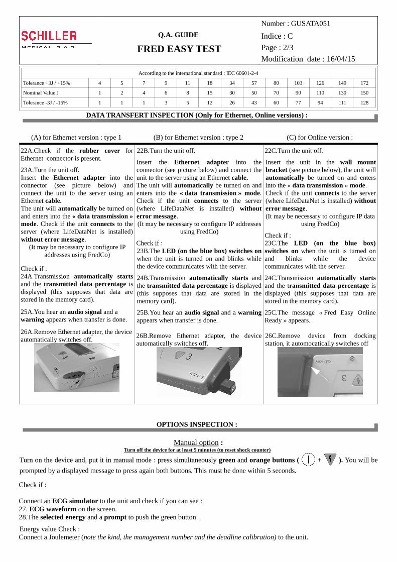
(A) for Ethernet version : type 1 (B) for Ethernet version : type 2 (C) for Online version :
22A.Check if the rubber cover for Ethernet connector is present.
23A.Turn the unit off.Insert the Ethernet adapter into the connector (see picture below) and connect the unit to the server using an Ethernet cable.The unit will automatically be turned on and enters into the « data transmission » mode. Check if the unit connects to the server (where LifeDataNet is installed) without error message.
(It may be necessary to configure IP addresses using FredCo)
Check if :24A.Transmission automatically starts and the transmitted data percentage is displayed (this supposes that data are stored in the memory card).
25A.You hear an audio signal and a warning appears when transfer is done.
26A.Remove Ethernet adapter, the device automatically switches off.
22B.Turn the unit off.
Insert the Ethernet adapter into the connector (see picture below) and connect the unit to the server using an Ethernet cable.The unit will automatically be turned on and enters into the « data transmission » mode. Check if the unit connects to the server (where LifeDataNet is installed) without error message.(It may be necessary to configure IP addresses
using FredCo)
Check if :23B.The LED (on the blue box) switches on when the unit is turned on and blinks while the device communicates with the server.
24B.Transmission automatically starts and the transmitted data percentage is displayed (this supposes that data are stored in the memory card).
25B.You hear an audio signal and a warning appears when transfer is done.
26B.Remove Ethernet adapter, the device automatically switches off.
22C.Turn the unit off.
Insert the unit in the wall mount bracket (see picture below), the unit will automatically be turned on and enters into the « data transmission » mode. Check if the unit connects to the server (where LifeDataNet is installed) without error message.(It may be necessary to configure IP data
using FredCo)
Check if :23C.The LED (on the blue box) switches on when the unit is turned on and blinks while the device communicates with the server.
24C.Transmission automatically starts and the transmitted data percentage is displayed (this supposes that data are stored in the memory card).
25C.The message « Fred Easy Online Ready » appears.
26C.Remove device from docking station, it automocatically switches off
OPTIONS INSPECTION :
Manual option :Turn off the device for at least 5 minutes (to reset shock counter)
Turn on the device and, put it in manual mode : press simultaneously green and orange buttons ( + ). You will be
prompted by a displayed message to press again both buttons. This must be done within 5 seconds.
Check if :
Connect an ECG simulator to the unit and check if you can see : 27. ECG waveform on the screen.28.The selected energy and a prompt to push the green button.
Energy value Check :Connect a Joulemeter (note the kind, the management number and the deadline calibration) to the unit.
Q.A. GUIDE
FRED EASY TEST
Number : GUSATA051
Indice : C
Page : 3/3
Modification date : 16/04/15
29.Press on green button to begin the charge of selected energy. When it's done, the orange button lights up and both a
voice prompt and a message ask you to deliver the shock (orange button).
Check if :30.There is an internal discharge after 20 seconds ± 1 sec without delivering shock.
31.Repeat 29th step and deliver 3 shocks (by pressing on orange button when unit asks it) using a Joulemeter to check the
delivered energies value. The values must imperatively be located between the tolerances (setting value ± 15%). Use the same table than in steps 21A and 21B to know nominal values tolerances.
(To return to the semiautomatic mode, switch off the unit and leave it turned off for at least 5 minutes.)
Metronome option :
32.Check if the unit generates a steady beat during cardiopulmonary resuscitation (CPR) to give the frequency for chest compressions (can be configured using FredCo Software).
ECG display option :
33.Connect an ECG simulator to the unit and check if you can see ECG waveform on the screen.
INSPECTION OF LEAKAGE CURRENTS (according to the international standard : IEC 60601-1 and 60601-2-4) :
34.Connect a leakage currents test device to the inputs/outputs of the device, note the kind, the serial number and the deadline calibration of the test device. The values must imperatively be located between the tolerances Has not to be performed during the 3 yearly maintenance, if the Easy has not been opened Has to be performed during the 6 yearly maintenance after the obliged replacement of the memory back up battery Has to be performed after a repair of the Easy (as soon as the Fred Easy has been opened)
ELECTRICAL CLASS UNIT : Internally powered
PATIENT LEAKAGE CURRENTAdmissible maximum values (µA)
Defibrillator IEC 60601-2-4 (BF)
Normal condition 100
Normal condition, reversed mains 100
PATIENT AUXILIARY CURRENTAdmissible maximum values (µA)
Defibrillator IEC 60601-2-4 (BF)
Normal condition 100
Normal condition, reversed mains 100
MAINS ON APPLIED PARTSAdmissible maximum values (µA)
Defibrillator IEC 60601-2-4 (BF)
Single fault condition 5000
Single fault condition, reversed mains 5000