gus canada manual r024 and operation manual for gus vawt wind turbines the manufacturer reserves all...
TRANSCRIPT

INSTRUCTION AND OPERATION MANUAL FOR GUS VAWT WIND TURBINES
The manufacturer reserves all rights to modifications without further notice.
Page: 2
04/08/2008
WELCOME
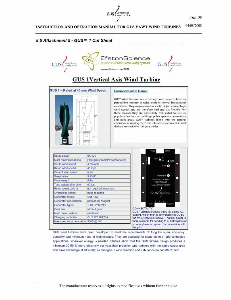
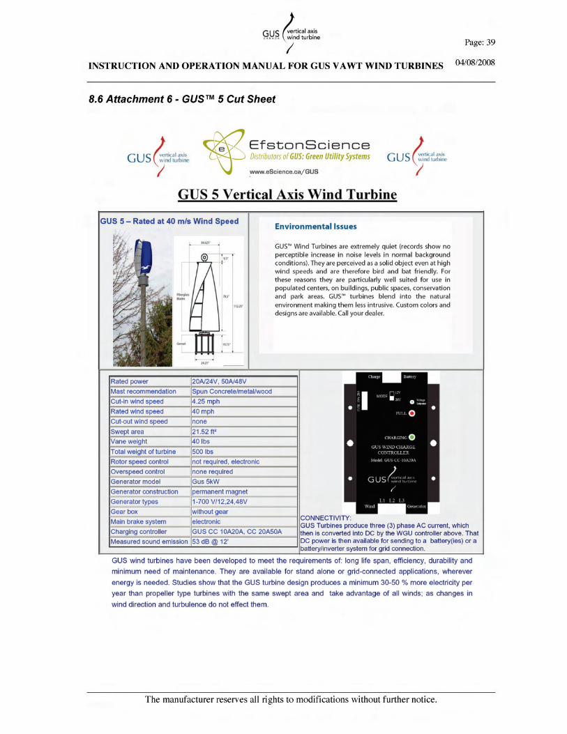
Thank you for your purchase of a GUS™ (Greenpower Utility System) vertical axis wind turbine (VAWT), a renewable energy electrical generator whose power source is the wind! GUS™ wind power plants are durable and have a long life span, thanks to their design and construction. GUS™ turbines are made to function in urban, rural, suburban, desert, coastal and mountainous regions, at sea and even in the exhaust streams of cooling/ventilation systems; wherever there is air moving and a need for energy. GUS™ turbines start producing energy at wind speeds as low as 4.5mph, so it can take advantage of even the gentlest of winds. Storms, ice, snow, sand or heat cannot break GUS™ wind turbines. The double helix shape of its vanes assures the turbine is always in the optimum direction towards wind. The bearings are sealed and there is no gearbox. That is why there is virtually no maintenance, and the turbine is very easy to use. In this manual you will find some basic information about wind energy, instructions on how to do the installation, maintenance and problem diagnosis. There are presently three different sizes of GUS wind turbines: - GUS™ 1, swept area 3.23 ft² - GUS™ 5, swept area 21.52 ft² - GUS™ 10, swept area 43.04 ft². In addition, there are two different wind ratings: - Model A, endures storm winds of 120 mph - Model B, endures storm winds of 80 mph Note: A-model turbines come in a frame and have a bearing at both ends, which must be taken into consideration when designing the mast structures.

INSTRUCTION AND OPERATION MANUAL FOR GUS VAWT WIND TURBINES
The manufacturer reserves all rights to modifications without further notice.
Page: 3
04/08/2008
WELCOME ....................................................................................................................................2
1. PRIMER ON WIND AND VERTICAL AXIS WIND TURBINES ....................................5
1.1. THE VERTICAL AXIS WIND TURBINE ................................................................................. 5 1.2 WHAT IS SWEPT AREA?....................................................................................................... 5 1.3. HOW MUCH POWER IS AVAILABLE FROM THE WIND?....................................................... 5 1.4 WHAT IS AVERAGE WIND SPEED?....................................................................................... 6
Example 1 ................................................................................................................................................................ 6 Example 2 ................................................................................................................................................................ 6
1.5 WHAT WILL A WIND TURBINE GENERATE AT DIFFERENT WIND SPEEDS?.......................... 7 1.5.1 Example Calculating the Available Power in Wind...................................................................................... 8
2. GUS™ TURBINE MODELS ..................................................................................................9
2.1 GUS™ TURBINE MODEL GUS™ 1..................................................................................... 9 2.2 GUS™ TURBINE MODEL GUS™ 5................................................................................... 10 2.3 GUS™ TURBINE MODEL GUS™ 10................................................................................. 11
3. CALCULATION OF TURBINE FORCES.........................................................................12
3.1 CALCULATION OF TURBINE LOADS ................................................................................... 12 3.1.1 Lateral Load Imparted on GUS™ Turbines by the Wind ........................................................................... 12
3.2 TURNING MOMENT AT BASE OF POLE OR TOWER. ............................................................. 12 3.3 ROTATIONAL FORCES IMPARTED BY THE TURBINES ON THE TOWER GUS™ 1 ................. 12
3.3.1 Turbine in Normal Operation Mode............................................................................................................ 12 3.3.2 Turbine in Stationary Mode. ........................................................................................................................ 13 3.3.3 Turbine in Free Rotation No Electrical Load. ............................................................................................ 13
4. INSTALLATION OF TURBINE .........................................................................................13
4.1 POLE MOUNTING ............................................................................................................... 13 4.1.1: Fiberglass................................................................................................................................................... 14 4.1.2: Spun Concrete............................................................................................................................................. 15 4.1.3 Further Requirements for Pole Mounting Turbines.................................................................................... 16 4.1.4 Side Mounting to a Structure:...................................................................................................................... 16
4.2 ELECTRICAL ...................................................................................................................... 16 4.2.1 Wiring ........................................................................................................................................................... 16 4.2.2 American Wire Gauge.................................................................................................................................. 17 4.2.2 Star vs. Delta ................................................................................................................................................ 20 4.2.3 What is the Difference between Star and Delta........................................................................................... 21 4.2.4 Star and Delta in the Real World................................................................................................................. 21
5. TURBINE OPERATIONS ....................................................................................................21
5.1 STOPPING THE TURBINE..................................................................................................... 21 5.2 EMERGENCY SHUT OFF SWITCH........................................................................................ 21 5.3 LIGHTNING PROTECTION. .................................................................................................. 22 5.4 REQUIREMENTS FOR ELECTRICAL SYSTEM......................................................................... 22 5.5 VARIOUS APPLICATION WIRING DIAGRAMS...................................................................... 22
5.5.1. Star and Delta ............................................................................................................................................. 22 5.5.2 Basic Turbine Battery Connection............................................................................................................... 23 5.5.3 Serial Connection......................................................................................................................................... 23 5.5.4 Parallel Connection ..................................................................................................................................... 24 5.5.5 Parallel Connection Wind Turbine and Photovoltaic Array ...................................................................... 25 5.5.6 GUS™ 1 (2 units) in Grid Connection ........................................................................................................ 26 5.5.7 GUS™ 10 in Grid Connect.......................................................................................................................... 27


INSTRUCTION AND OPERATION MANUAL FOR GUS VAWT WIND TURBINES
The manufacturer reserves all rights to modifications without further notice.
Page: 5
04/08/2008
1. Primer on Wind and Vertical Axis Wind Turbines
1.1. The Vertical Axis Wind Turbine Generated power over time is a more important figure than peak power available only a small proportion of the time. Our VAWT with an operating range from 4 – 135 mph, depending on model, offers better performance on a kilowatt-hour per square meter of blade area (Swept Area), than a comparable Horizontal Axis Wind Turbine, HAWT (i. e. propeller). Of equal importance is that these wind turbines are virtually soundless, measuring no more than 53 dB at six (6’) from the base of the pole. This virtually noiseless operation makes it ideal for urban environments along with its compact profile and attractive appearance.
1.2 What is Swept Area? The swept area of a turbine is the area in space that is acted on by the wind. For our VAWT this is the height of the vane multiplied by the diameter.
Example 1) A GUS™ 10 Vane is 4m tall x 1m in diameter. 4m x 1m = 4m² 2) For a propeller this would be the area of the circle the blade covers in a full rotation.
Propeller Swept area = π x r² where; r = radius of turbine. π = 3.142
1.3. How Much Power is Available From The Wind? This of course depends on how fast the wind is blowing. The figures used in the examples below are the theoretical power available.
Example At wind speed of 5m/s theoretical power available is 77 W/m² At wind speed of 10m/s theoretical power available is 613 W/m²
The above two figures are used to illustrate the exponential nature of power available in the wind with relation to wind speed. In the first example the wind speed is 5m/s and in the second 10m/s. This shows a two-fold increase in wind speed. Respectively the power available at 5 m/s is 77 W/m² while the power available at 10 m/s is 613 W/m². This shows an eight-fold increase in power available at just twice the wind speed. It is important to note available wind speeds are often much closer to the lower figure of 5m/s than they are to the higher figure of 10m/s.
INSTRUCTION AND OPERATION MANUAL FOR GUS VAWT WIND TURBINES
The manufacturer reserves all rights to modifications without further notice.
Page: 6
04/08/2008
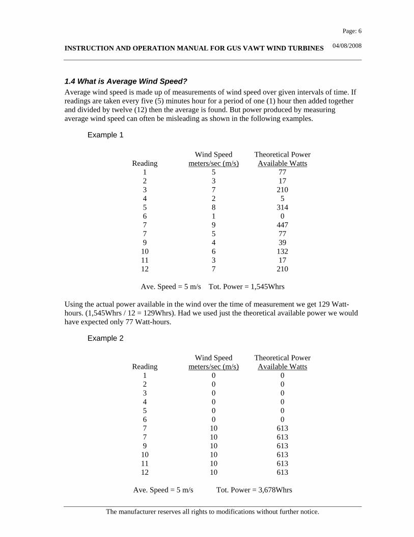
1.4 What is Average Wind Speed? Average wind speed is made up of measurements of wind speed over given intervals of time. If readings are taken every five (5) minutes hour for a period of one (1) hour then added together and divided by twelve (12) then the average is found. But power produced by measuring average wind speed can often be misleading as shown in the following examples.
Example 1 Wind Speed Theoretical Power Reading meters/sec (m/s) Available Watts 1 5 77 2 3 17 3 7 210 4 2 5 5 8 314 6 1 0 7 9 447 7 5 77 9 4 39 10 6 132 11 3 17 12 7 210
Ave. Speed = 5 m/s Tot. Power = 1,545Whrs Using the actual power available in the wind over the time of measurement we get 129 Watt-hours. (1,545Whrs / 12 = 129Whrs). Had we used just the theoretical available power we would have expected only 77 Watt-hours.
Example 2 Wind Speed Theoretical Power Reading meters/sec (m/s) Available Watts 1 0 0 2 0 0 3 0 0 4 0 0 5 0 0 6 0 0 7 10 613 7 10 613 9 10 613 10 10 613 11 10 613 12 10 613
Ave. Speed = 5 m/s Tot. Power = 3,678Whrs

INSTRUCTION AND OPERATION MANUAL FOR GUS VAWT WIND TURBINES
The manufacturer reserves all rights to modifications without further notice.
Page: 7
04/08/2008
Example 2 also shows 12 hourly readings that also give an average of 5m/s. Using the actual power available in the wind at the time of measurement 306 Watt-hours (3,678Whrs / 12 = 306Whrs). Had we used just the theoretical available power we would have expected only 77 Watt-hours. In summary our 5 m/s wind speed can be shown to produce anywhere from 77, 129, 306 Watt-hours. It all depends on how the actual wind speed is experienced over time. These two examples are simple examples used to illustrate that average wind speeds can be misleading and that exactly how averages are made up is important on what is actually generated. The technical term for this is "The Weibull Distribution" and a good explanation for this can be found on the following web page, published by the Danish Wind Industry Association. http://www.windpower.org/en/tour/wres/weibull.htm
1.5 What Will a Wind Turbine Generate at Different Wind Speeds? We have already seen that Wind Speed is a critical factor in the availability of power. The method of converting the wind to electrical power is a function of the wind turbine and the generator. Critical factors here are the wind turbine swept area. If a wind turbine were 100% efficient then at 10m/s wind speed when power available in the wind is 613 W/m² with a swept area of 10m² the power generated would be 10 m² x 613 W/m² = 6130 W.
Note: Wind turbines can't be 100% efficient though, and in real terms the best that could be expected in perfect 10m/s wind speed is about 35%. This is shown in the following example.

INSTRUCTION AND OPERATION MANUAL FOR GUS VAWT WIND TURBINES
The manufacturer reserves all rights to modifications without further notice.
Page: 8
04/08/2008
1.5.1 Example Calculating the Available Power in Wind Air has mass and when it moves as wind it has kinetic energy. Kinetic energy is measured in joules. KE = 0.5 x m x V² where; m is mass in kg V is velocity in m/s Since energy = power x density x time and we are interested in power which is a more convenient way of expressing a mass of flowing air then we use the following equation. P = 0.5 x rho x A x V³ where; P is power in Watts. rho is density of air in kg/m³ A is the swept area in m² V is the wind speed in m/s Therefore with a wind speed of 10 m/s. and a swept area of 10 m² theoretical power available is P=0.5 x 1.23 x 10 x 10³ P = 6150 watts. While good turbine design will harness circa 35% of this power you have electrical losses, generator losses and mechanical losses and bearings that reduce this still further. This goes to demonstrate how difficult it can be to project the power one will get from any given “average” wind speed.

INSTRUCTION AND OPERATION MANUAL FOR GUS VAWT WIND TURBINES
The manufacturer reserves all rights to modifications without further notice.
Page: 9
04/08/2008
2. GUS™ Turbine Models
2.1 GUS™ Turbine Model GUS™ 1

INSTRUCTION AND OPERATION MANUAL FOR GUS VAWT WIND TURBINES
The manufacturer reserves all rights to modifications without further notice.
Page: 10
04/08/2008
2.2 GUS™ Turbine Model GUS™ 5

INSTRUCTION AND OPERATION MANUAL FOR GUS VAWT WIND TURBINES
The manufacturer reserves all rights to modifications without further notice.
Page: 11
04/08/2008
2.3 GUS™ Turbine Model GUS™ 10
INSTRUCTION AND OPERATION MANUAL FOR GUS VAWT WIND TURBINES
The manufacturer reserves all rights to modifications without further notice.
Page: 12
04/08/2008
3. Calculation of Turbine Forces
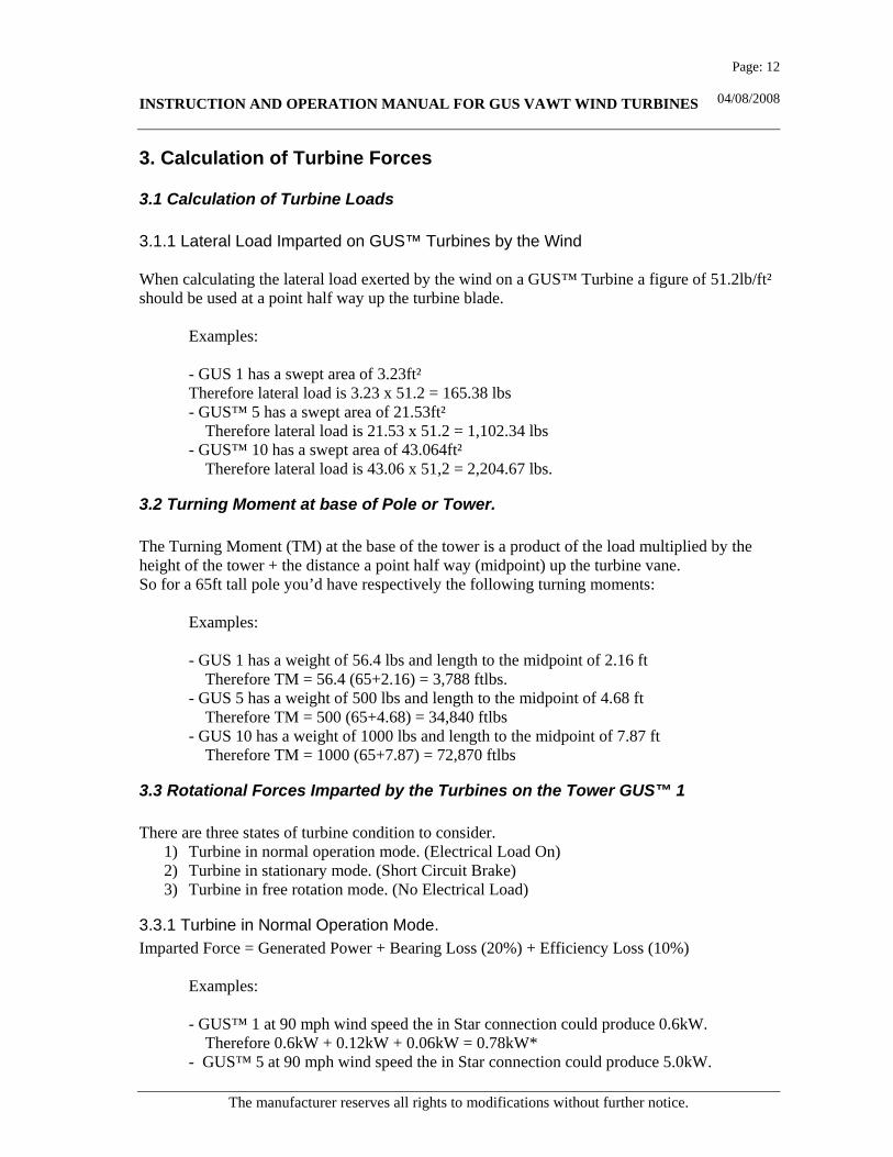
3.1 Calculation of Turbine Loads 3.1.1 Lateral Load Imparted on GUS™ Turbines by the Wind When calculating the lateral load exerted by the wind on a GUS™ Turbine a figure of 51.2lb/ft² should be used at a point half way up the turbine blade.
Examples: - GUS 1 has a swept area of 3.23ft² Therefore lateral load is 3.23 x 51.2 = 165.38 lbs - GUS™ 5 has a swept area of 21.53ft² Therefore lateral load is 21.53 x 51.2 = 1,102.34 lbs - GUS™ 10 has a swept area of 43.064ft² Therefore lateral load is 43.06 x 51,2 = 2,204.67 lbs.
3.2 Turning Moment at base of Pole or Tower. The Turning Moment (TM) at the base of the tower is a product of the load multiplied by the height of the tower + the distance a point half way (midpoint) up the turbine vane. So for a 65ft tall pole you’d have respectively the following turning moments:
Examples: - GUS 1 has a weight of 56.4 lbs and length to the midpoint of 2.16 ft Therefore TM = 56.4 (65+2.16) = 3,788 ftlbs. - GUS 5 has a weight of 500 lbs and length to the midpoint of 4.68 ft Therefore TM = 500 (65+4.68) = 34,840 ftlbs - GUS 10 has a weight of 1000 lbs and length to the midpoint of 7.87 ft Therefore TM = 1000 (65+7.87) = 72,870 ftlbs
3.3 Rotational Forces Imparted by the Turbines on the Tower GUS™ 1 There are three states of turbine condition to consider.
1) Turbine in normal operation mode. (Electrical Load On) 2) Turbine in stationary mode. (Short Circuit Brake) 3) Turbine in free rotation mode. (No Electrical Load)
3.3.1 Turbine in Normal Operation Mode. Imparted Force = Generated Power + Bearing Loss (20%) + Efficiency Loss (10%)
Examples: - GUS™ 1 at 90 mph wind speed the in Star connection could produce 0.6kW. Therefore 0.6kW + 0.12kW + 0.06kW = 0.78kW* - GUS™ 5 at 90 mph wind speed the in Star connection could produce 5.0kW.

INSTRUCTION AND OPERATION MANUAL FOR GUS VAWT WIND TURBINES
The manufacturer reserves all rights to modifications without further notice.
Page: 13
04/08/2008
Therefore 5.0kW + 1.0kW + 0.5kW = 6.50kW* - GUS™ 10 at 90 mph wind speed the in Star connection could produce 10.kW. Therefore 10.0kW + 2.0kW + 1.0kW = 13.0kW*
3.3.2 Turbine in Stationary Mode. Imparted Force = 30% of Available Kinetic Energy in the wind for Swept Area. At 90 mph wind speed the available Kinetic Energy is 3643 W/ft²
Examples: - GUS 1 has swept area of 3.23ft² Therefore 3643 x 3.23x 0.3 = 3528 Watts or 3.53 kW* - GUS™ 5 has a swept area of 21.53ft² Therefore 3643 x 21.53 x 0.3 = 23,530 Watts or 23.53 kW - GUS™ 10 has a swept area of 43.064ft² Therefore 3643 x 43.06 x 0.3 = 47040 Watts or 47.06 kW
3.3.3 Turbine in Free Rotation No Electrical Load. This is a state that should normally be avoided as it means turbine tip speed can be up to 1.7 x wind speed. Although this is not a problem at low wind speeds it could cause bearing problems at high wind speeds. Imparted Force = 20% of the Generator Power due to Bearing Losses
Examples: - GUS 1 at 90 mph wind speed the in Star connection could produce 0.6kW. Therefore 0.6 kW x 0.2 = 0.12 kW* - GUS™ 5 at 90 mph wind speed the in Star connection could produce 5.0kW. Therefore 5.0kW x 0.2 = 1.0kW* - GUS™ 10 at 90 mph wind speed the in Star connection could produce 10.kW. Therefore 10.0kW x 0.2 = 2.0kW* *Note. 1 kW = 1.341 Horsepower.
4. Installation of Turbine
4.1 Pole Mounting When using a metal installation mast/tower, a concrete slab with fastening bolts must be cast. The concrete used in the slab must be frost-proof. The slab must be grounded well, and it must reach the depth free from frost. Otherwise the frost is able to bend the structures, and the turbine is in danger of falling down. The upper side of the slab must be cast with a small slope, so that water will run off and not rust the fastening bolts.
INSTRUCTION AND OPERATION MANUAL FOR GUS VAWT WIND TURBINES
The manufacturer reserves all rights to modifications without further notice.
Page: 14
04/08/2008
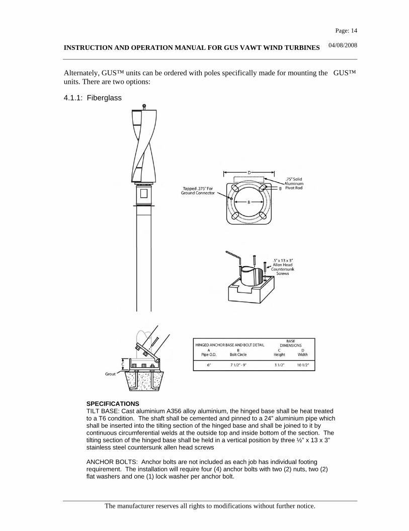
Alternately, GUS™ units can be ordered with poles specifically made for mounting the GUS™ units. There are two options:
4.1.1: Fiberglass
SPECIFICATIONS TILT BASE: Cast aluminium A356 alloy aluminium, the hinged base shall be heat treated to a T6 condition. The shaft shall be cemented and pinned to a 24” aluminium pipe which shall be inserted into the tilting section of the hinged base and shall be joined to it by continuous circumferential welds at the outside top and inside bottom of the section. The tilting section of the hinged base shall be held in a vertical position by three ½” x 13 x 3” stainless steel countersunk allen head screws ANCHOR BOLTS: Anchor bolts are not included as each job has individual footing requirement. The installation will require four (4) anchor bolts with two (2) nuts, two (2) flat washers and one (1) lock washer per anchor bolt.

INSTRUCTION AND OPERATION MANUAL FOR GUS VAWT WIND TURBINES
The manufacturer reserves all rights to modifications without further notice.
Page: 15
04/08/2008
4.1.2: Spun Concrete
Poles shall be prestressed and/or reinforced concrete with dimensions, tapers and cross-sections as engineered for each application.. The concrete used shall achieve a minimum 28 day compressive strength, of 8,000 psi. Poles shall be steam cured to a 3-day strength, and thereafter stored under cover for 72 hours at a minimum temperature of 50 degrees Fahrenheit (10 degrees Celsius). In areas subject to frequent freeze/thaw conditions an air entrainment admixture shall be used to produce a 5-8% air content in the mix. Prestressing steel reinforcement shall be stressed to a maximum of 70% of their ultimate capacity, and shall not be released until a minimum compressive strength of 3,500 psi has been achieved.
INSTRUCTION AND OPERATION MANUAL FOR GUS VAWT WIND TURBINES
The manufacturer reserves all rights to modifications without further notice.
Page: 16
04/08/2008
4.1.3 Further Requirements for Pole Mounting Turbines When selecting the location for the turbine, service, operations and safety aspects must be taken into consideration. The turbine must be located, if possible, in an open place. In a tree growth area or in a place surrounded by buildings the turbine must be installed twelve feet (12’) above the surrounding obstacles, so that the turbine is able to take advantage of winds blowing from any direction. The height should be at least thirty feet (30’) above ground level in all circumstances. The higher you install the turbine, the better results you will experience. The use of guy wires must be avoided, because they can cause resonance to the structures. If guy wires are being used, however, plastic rope must be wound around them in order to reduce resonance.
4.1.4 Side Mounting to a Structure: The small GUS™ 1 wind turbine can be fastened to the side of a solid wall or structure. The distance between the side of the structure and the vane of the turbine must be 1.75 feet so that the aerodynamic characteristics of the turbine are not disturbed. The bigger models, GUS™ 5 and GUS™ 10, must have a supporting structure designed by a licensed Professional Engineer. In order to ease the service situations, it would be advisable to build a swinging boom at the upper end, with which the turbine can be lifted if the generator must be temporarily removed. The supporting structures must extend a distance of 5 feet from the side of the structure so that the aerodynamic characteristics of the turbine are not disturbed.
4.2 Electrical
4.2.1 Wiring WARNING! During all the connecting work the rotation of the generator must be stopped, because the voltage produced by the generator is highly dangerous. Before placing the turbine into use, it is advisable to get all the other connections made before connecting the generator. When wiring the turbine and connecting, the other components i.e. the charge controller and the batteries must be placed in the same space (the charge controller is non-arcing). The temperature of that space should be between 35º F and 90 ºF steady and it must have good air circulation, so that the operating time can be maximised. The generators of the models GUS™ 1 shall be connected with a cable of 3*AWG 10 and the models GUS™ 5 and GUS™ 10 with one of 3*AWG 2 to the rectifier or the controller. The cable must be TC Tray Cable which is UV resistant and Direct Bury rated. The batteries shall be connected to GUS™ Wind Charge Controller 10A20A. This must be done with PVC-cable, the cross-sectional area of which is either 2*AWG 14 (GUS™ 1) or 2*AWG 12 (GUS™ 5 and GUS™ 10). This is assuming less than 6 feet between the Charge Controller and the Batteries. Thicker AWG wire will be needed in excess of 6 feet, refer to the charts in section 4.2.2. The wires must be connected carefully, since especially the wire coming from the generator is exposed to stress caused by the wind. The battery poles must be connected carefully and the +
INSTRUCTION AND OPERATION MANUAL FOR GUS VAWT WIND TURBINES
The manufacturer reserves all rights to modifications without further notice.
Page: 17
04/08/2008
and – poles must not be mixed. An incorrect connection causes damage and at least would blow the fuse. The wires must never cause tension to the connections: the connections must be protected with tension removers. The electric conducting wires must never be free; the electric circuit must always be closed and protected!
4.2.2 American Wire Gauge Load Carrying Capacities (see table on next page) The following chart is a guideline of ampacity or copper wire current carrying capacity following the Handbook of Electronic Tables and Formulas for American Wire Gauge. As you might guess, the rated ampacities are just a rule of thumb. In careful engineering the voltage drop, insulation temperature limit, thickness, thermal conductivity, and air convection and temperature should all be taken into account. The Maximum Amps for Power Transmission uses the 700 circular mils per amp rule, which is very, very conservative. The Maximum Amps for Chassis Wiring is also a conservative rating, but is meant for wiring in air, and not in a bundle. For short lengths of wire, such as is used in battery packs you should trade off the resistance and load with size, weight, and flexibility. Some local codes supersede the National Electrical Code (NEC), refer to local wiring codes for installation of this type of equipment.

INSTRUCTION AND OPERATION MANUAL FOR GUS VAWT WIND TURBINES
The manufacturer reserves all rights to modifications without further notice.
Page: 18
04/08/2008
American Wire Gauge AWG
Conductor ConductorMaximum amps for Maximum freqency for
Diameter Inches Diameter mmpower transmission
100% skin depth for solid conductor copper
OOOO 0.46 11.684 0.049 0.16072 380 302 125 HzOOO 0.4096 10.40384 0.0618 0.202704 328 239 160 HzOO 0.3648 9.26592 0.0779 0.255512 283 190 200 Hz
0 0.3249 8.25246 0.0983 0.322424 245 150 250 Hz1 0.2893 7.34822 0.1239 0.406392 211 119 325 Hz2 0.2576 6.54304 0.1563 0.512664 181 94 410 Hz3 0.2294 5.82676 0.197 0.64616 158 75 500 Hz4 0.2043 5.18922 0.2485 0.81508 135 60 650 Hz5 0.1819 4.62026 0.3133 1.027624 118 47 810 Hz6 0.162 4.1148 0.3951 1.295928 101 37 1100 Hz7 0.1443 3.66522 0.4982 1.634096 89 30 1300 Hz8 0.1285 3.2639 0.6282 2.060496 73 24 1650 Hz9 0.1144 2.90576 0.7921 2.598088 64 19 2050 Hz
10 0.1019 2.58826 0.9989 3.276392 55 15 2600 Hz11 0.0907 2.30378 1.26 4.1328 47 12 3200 Hz12 0.0808 2.05232 1.588 5.20864 41 9.3 4150 Hz13 0.072 1.8288 2.003 6.56984 35 7.4 5300 Hz14 0.0641 1.62814 2.525 8.282 32 5.9 6700 Hz15 0.0571 1.45034 3.184 10.44352 28 4.7 8250 Hz16 0.0508 1.29032 4.016 13.17248 22 3.7 11 k Hz17 0.0453 1.15062 5.064 16.60992 19 2.9 13 k Hz18 0.0403 1.02362 6.385 20.9428 16 2.3 17 kHz19 0.0359 0.91186 8.051 26.40728 14 1.8 21 kHz20 0.032 0.8128 10.15 33.292 11 1.5 27 kHz21 0.0285 0.7239 12.8 41.984 9 1.2 33 kHz22 0.0254 0.64516 16.14 52.9392 7 0.92 42 kHz23 0.0226 0.57404 20.36 66.7808 4.7 0.729 53 kHz24 0.0201 0.51054 25.67 84.1976 3.5 0.577 68 kHz25 0.0179 0.45466 32.37 106.1736 2.7 0.457 85 kHz26 0.0159 0.40386 40.81 133.8568 2.2 0.361 107 kH27 0.0142 0.36068 51.47 168.8216 1.7 0.288 130 kHz28 0.0126 0.32004 64.9 212.872 1.4 0.226 170 kHz29 0.0113 0.28702 81.83 268.4024 1.2 0.182 210 kHz30 0.01 0.254 103.2 338.496 0.86 0.142 270 kHz31 0.0089 0.22606 130.1 426.728 0.7 0.113 340 kHz32 0.008 0.2032 164.1 538.248 0.53 0.091 430 kHz
Metric 2.0 0.00787 0.2 169.39 555.61 0.51 0.088 440 kHz
33 0.0071 0.18034 206.9 678.632 0.43 0.072 540 kHzMetric 1.8 0.00709 0.18 207.5 680.55 0.43 0.072 540 kHz
34 0.0063 0.16002 260.9 855.752 0.33 0.056 690 kHzMetric 1.6 0.0063 0.16002 260.9 855.752 0.33 0.056 690 kHz
35 0.0056 0.14224 329 1079.12 0.27 0.044 870 kHzMetric 1.4 0.00551 0.14 339 1114 0.26 0.043 900 kHz
36 0.005 0.127 414.8 1360 0.21 0.035 1100 kHzMetric 1.25 0.00492 0.125 428.2 1404 0.2 0.034 1150 kHz
37 0.0045 0.1143 523.1 1715 0.17 0.0289 1350 kHzMetric 1.12 0.00441 0.112 533.8 1750 0.163 0.0277 1400 kHz
38 0.004 0.1016 659.6 2163 0.13 0.0228 1750 kHzMetric 1 0.00394 0.1 670.2 2198 0.126 0.0225 1750 kHz
39 0.0035 0.0889 831.8 2728 0.11 0.0175 2250 kHz40 0.0031 0.07874 1049 3440 0.09 0.0137 2900 kHz
AWG gauge
Ohms per 1000 ft
Ohms per km
Maximum amps for chassis wiring

INSTRUCTION AND OPERATION MANUAL FOR GUS VAWT WIND TURBINES
The manufacturer reserves all rights to modifications without further notice.
Page: 19
04/08/2008
National Electrical Code – Table 310.16
INSTRUCTION AND OPERATION MANUAL FOR GUS VAWT WIND TURBINES
The manufacturer reserves all rights to modifications without further notice.
Page: 20
04/08/2008
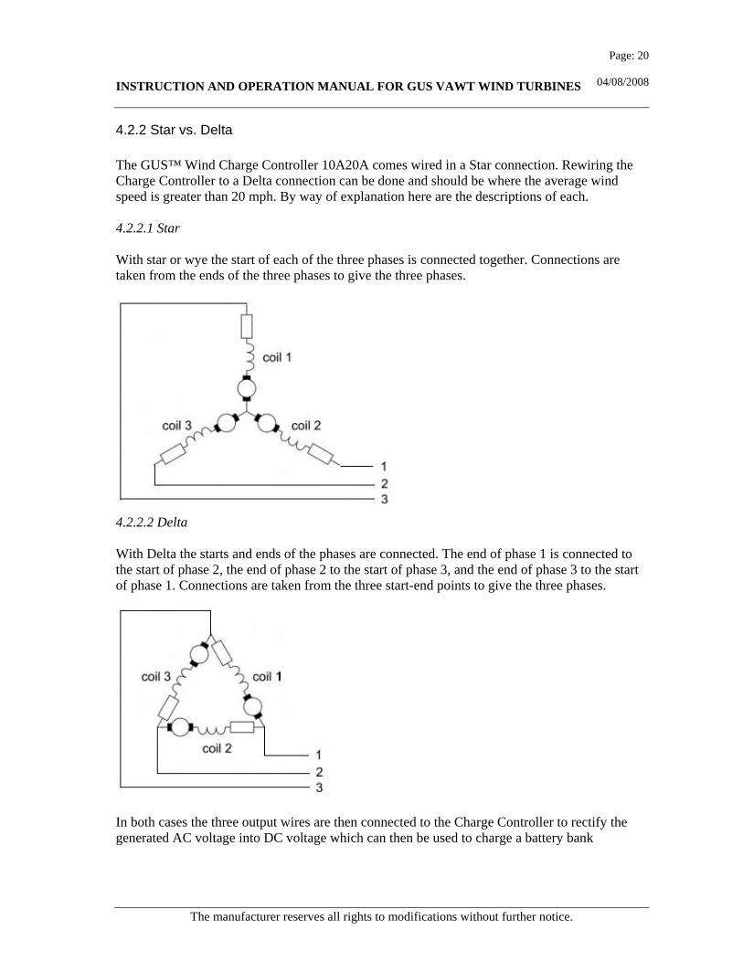
4.2.2 Star vs. Delta The GUS™ Wind Charge Controller 10A20A comes wired in a Star connection. Rewiring the Charge Controller to a Delta connection can be done and should be where the average wind speed is greater than 20 mph. By way of explanation here are the descriptions of each. 4.2.2.1 Star With star or wye the start of each of the three phases is connected together. Connections are taken from the ends of the three phases to give the three phases.
4.2.2.2 Delta With Delta the starts and ends of the phases are connected. The end of phase 1 is connected to the start of phase 2, the end of phase 2 to the start of phase 3, and the end of phase 3 to the start of phase 1. Connections are taken from the three start-end points to give the three phases.
In both cases the three output wires are then connected to the Charge Controller to rectify the generated AC voltage into DC voltage which can then be used to charge a battery bank
INSTRUCTION AND OPERATION MANUAL FOR GUS VAWT WIND TURBINES
The manufacturer reserves all rights to modifications without further notice.
Page: 21
04/08/2008
4.2.3 What is the Difference between Star and Delta The basic difference between star and delta is that star generates a high voltage at a low current, and delta generates a low voltage at a high current. The total (no load) power generated is the same. To calculate the output AC voltage and current of a three-phase alternator wired in star or delta it is only necessary to measure the voltage and current of one of the coils. Then the square root of the number of phases (3) = 1.732 can be used to calculate the total outputs with either configuration. For example, if you have one coil which gives 20 Volts at 12 Amps: Star - Voltage = 20 * 1.732 = 34.6V, Current is unchanged at 12 Amps. Delta - Voltage is unchanged at 20 Volts, Current = 12 X 1.732 = 20.8 Amps. Note that since power is equal to the voltage multiplied by the current, in both cases the power is around 415 Watts in the example above.
4.2.4 Star and Delta in the Real World Since star and delta wiring both give the same power, why does it matter which is used? A GUS™ wind turbine wired in Star will generate a higher voltage at lower RPM and will therefore start charging the battery bank sooner. A GUS™ wind turbine wired in Delta also requires more effort (wind) to get it turning. You are usually better off wiring in the Star configuration. Star is generally more efficient, you will start charging your batteries earlier, and the higher voltage means you can use thinner (therefore cheaper) power transmitting cables without incurring large line losses in your system.
5. Turbine Operations
5.1 Stopping the Turbine After mounting and connecting the turbine you must assure that it is able to rotate freely. Once properly installed, that is connected to the Controller and to a load; the turbine must not be locked mechanically but always be allowed to rotate with the normal accessories connected. A service situation is the only exception, when the rotation must be stopped and restrained in order to ensure the safety of the service personnel.
5.2 Emergency Shut Off Switch. It is possible to slow the turbine to a virtual standstill by use of an emergency shut off switch. This is connected in the 3 phase section of the circuit between the generator and the rectifier/voltage controller. This switch is normally in the open position and allows the turbine to rotate normally. When the switch is closed it short circuits the 3 phases and slows the turbine to a near standstill. This is not a mandatory requirement of GUS™ but an option we strongly recommend installing.

INSTRUCTION AND OPERATION MANUAL FOR GUS VAWT WIND TURBINES
The manufacturer reserves all rights to modifications without further notice.
Page: 22
04/08/2008
5.3 Lightning Protection. In order to protect the turbine against lightning, a copper cable (AWG OOO) must be led from the fastening cylinder or the fastening flange into earth. This is important especially in the situation where the turbine is placed higher than the surrounding terrain and/or structures. The earthing can be done with an earthing stick, which must be steeped in moist earth to the depth of min. 6 feet, if possible. If the use of an earthing stick is not possible, the earthing must be led horizontally, under ground level. The best and cheapest way to do this is to assemble two parallel cables connected to each other so that the space between them is 8 inches. The length of the cables under ground level must be min. 65 feet. If the turbine has been assembled remarkably high up and the area is exposed to lightning, the protection needs special attention. In this case, the feed cable should be equipped with lightning arresters, and the same earthing as that of the turbine should be used.
5.4 Requirements for electrical system The installation of GUS™ wind turbines, which have been designed and manufactured to function stand alone or grid connected, must meet electricity safety regulations. That is why a licensed electrician or certified technician are the best choice for installing the equipment.
5.5 Various Application Wiring Diagrams Following are several representative wiring diagrams for turbine applications
5.5.1. Star and Delta
INSTRUCTION AND OPERATION MANUAL FOR GUS VAWT WIND TURBINES
The manufacturer reserves all rights to modifications without further notice.
Page: 23
04/08/2008
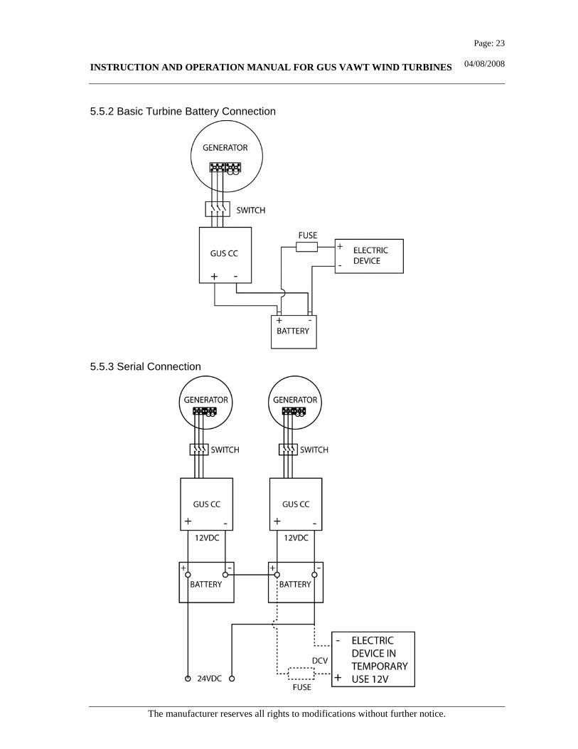
5.5.2 Basic Turbine Battery Connection
5.5.3 Serial Connection

INSTRUCTION AND OPERATION MANUAL FOR GUS VAWT WIND TURBINES
The manufacturer reserves all rights to modifications without further notice.
Page: 24
04/08/2008
5.5.4 Parallel Connection

INSTRUCTION AND OPERATION MANUAL FOR GUS VAWT WIND TURBINES
The manufacturer reserves all rights to modifications without further notice.
Page: 25
04/08/2008
5.5.5 Parallel Connection Wind Turbine and Photovoltaic Array
INSTRUCTION AND OPERATION MANUAL FOR GUS VAWT WIND TURBINES
The manufacturer reserves all rights to modifications without further notice.
Page: 26
04/08/2008
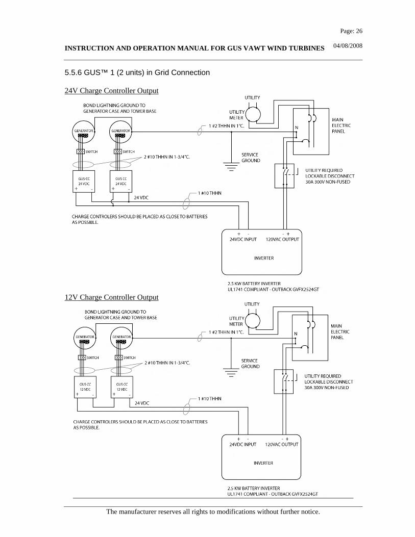
5.5.6 GUS™ 1 (2 units) in Grid Connection 24V Charge Controller Output
12V Charge Controller Output
INSTRUCTION AND OPERATION MANUAL FOR GUS VAWT WIND TURBINES
The manufacturer reserves all rights to modifications without further notice.
Page: 27
04/08/2008
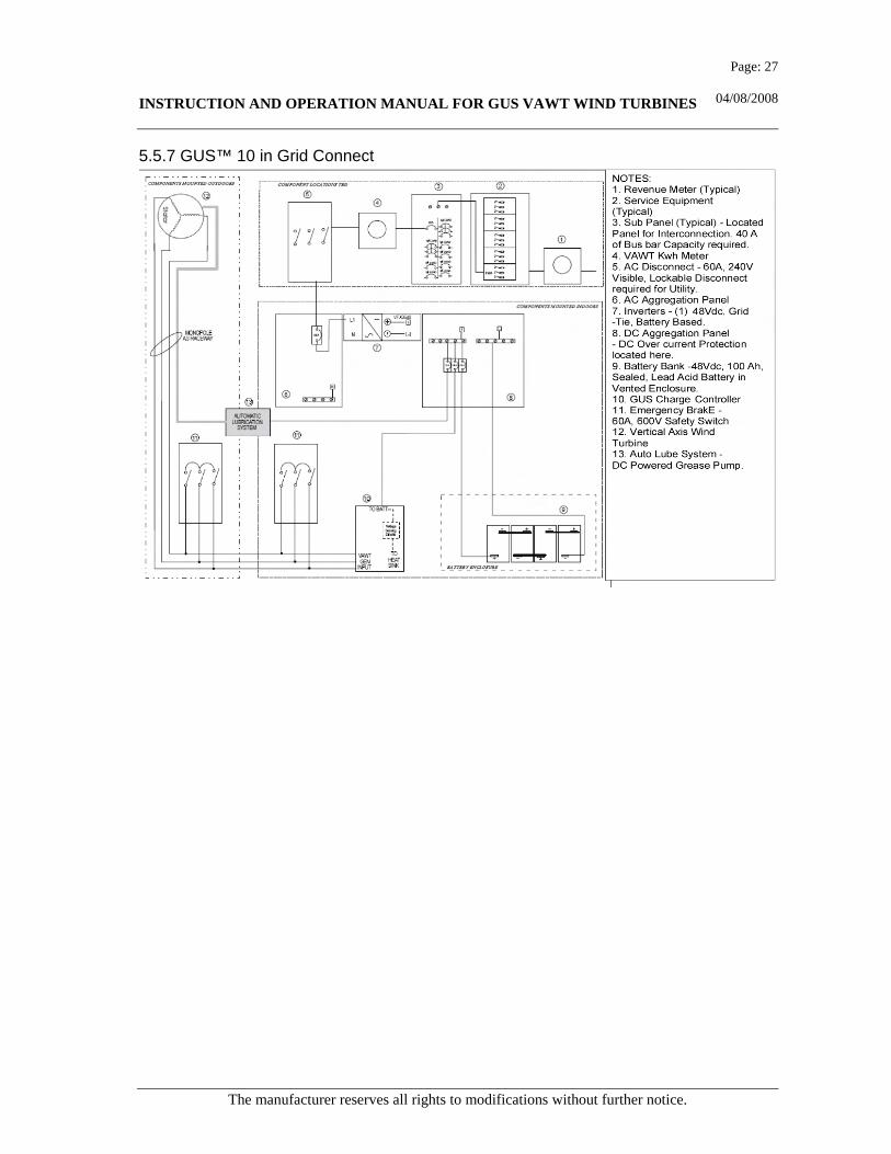
5.5.7 GUS™ 10 in Grid Connect

INSTRUCTION AND OPERATION MANUAL FOR GUS VAWT WIND TURBINES
The manufacturer reserves all rights to modifications without further notice.
Page: 28
04/08/2008
5.5.8 GUS™-1 Charging Controller Control Features: • Suitable for a Y or Delta Connected 3
phase wind generator • 10 Amp and 20 Amp version models • Separate phase Schottky Rectifiers for
fast switching times and low on resistance
• Reverse current protection for the generator with Schottky blocking rectifiers
• Red LED to indicate batteries are charging
• Green LED to indicate batteries are fully charged
• Over current protection with ATO type fused output
• Terminal blocks for easy connections to input and output wiring
• Switch selectable for 12V or 24V battery operation
• User adjustable set point voltage • Electronic generator braking when
batteries are fully charged • Advanced PCB design for optimum
current loading and thermal conductivity
• Black anodized aluminium base and cover for optimum thermal conductivity
• Suitable for deep cycle lead acid, gel cell type rechargeable batteries
Specifications: • Maximum input voltage: 120VAC
Maximum input current: 10A/20A • Terminal block wiring: 26-10 AWG
wire, 300V @ 30A • Set point is factory set to mid position:
13V on and 14V off for a 12V system and 26V on and 28V off for a 24V system for potentiometer at mid point
12V System 24V System Set Point On Off On Off FCCW 11V 12V 22V 24V
CENTER 13V 14V 26V 28V FCW 17V 18V 34V 36V
• Controller dimensions: Base: 4” x 6” x x.25” Cover: 3” x 6” x x.85” Total Weight: 430 gms (15oz)
• Temperature range: Operating: 14°F.to.185°F Storage: -85°F.to.347°F
• Unit should be vertically mounted in a well ventilated electrical cabinet or panel
Mounting Dimensions: Six (6) .2” Mounting Holes Three (3) Mounting Holes on left side spaced 2 ¾” apart (5 ½” from top to bottom) Three (3) Mounting Holes on right side spaced identical to left side Left and right columns are 3 ½” apart
INSTRUCTION AND OPERATION MANUAL FOR GUS VAWT WIND TURBINES
The manufacturer reserves all rights to modifications without further notice.
Page: 29
04/08/2008
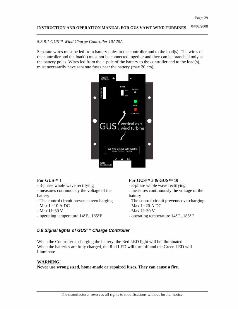
5.5.8.1 GUS™ Wind Charge Controller 10A20A Separate wires must be led from battery poles to the controller and to the load(s). The wires of the controller and the load(s) must not be connected together and they can be branched only at the battery poles. Wires led from the + pole of the battery to the controller and to the load(s), must necessarily have separate fuses near the battery (max 20 cm).
For GUS™ 1 - 3-phase whole wave rectifying - measures continuously the voltage of the battery - The control circuit prevents overcharging - Max I =10 A DC - Max U=30 V - operating temperature 14°F...185°F
For GUS™ 5 & GUS™ 10 - 3-phase whole wave rectifying - measures continuously the voltage of the battery - The control circuit prevents overcharging - Max I =20 A DC - Max U=30 V - operating temperature 14°F...185°F
5.6 Signal lights of GUS™ Charge Controller When the Controller is charging the battery, the Red LED light will be illuminated. When the batteries are fully charged, the Red LED will turn off and the Green LED will illuminate. WARNING! Never use wrong sized, home-made or repaired fuses. They can cause a fire.

INSTRUCTION AND OPERATION MANUAL FOR GUS VAWT WIND TURBINES
The manufacturer reserves all rights to modifications without further notice.
Page: 30
04/08/2008
5.7 Batteries and load The ampere hours of the batteries must be calculated according to the purpose of use, and attention must be paid to power and usage time of devices. To increase the capacity, batteries can be connected in parallel if: - The number of elements of the batteries is the same - The density of the acid of the batteries is the same - The batteries are of the same type (compounds) To raise the voltage level, batteries can be connected in series provided that: - The capacity of the elements is the same - The elements are of the same type - The elements are of the same age - The density of the acid of the elements is the same The batteries must be placed in a space that has steady temperature (ideally room temperature) so that the operation time will be as long as possible. Firm, 18 inch-high bases should be built for the batteries in order to ease service situations. The load devices shall be connected to the couplers in the charging controller. If the charging controller is not a part of the assembly, the load should always be connected to the batteries through a fuse.
6 CONTROL AND SERVICE
6.1 Bearings The GUS™ 1 bearings never require lubrication. For the GUS™ 5 and the GUS™ 10 the first lubrication of bearings shall be done within 2-6 months after the installation of the device. After this, the lubrication should be done twice a year (depending on circumstances). The lubrication is done by pressing grease 6 times with a grease gun to the grease nipples under the centrifugal shield and at the lower end of the generator. GUS™ Grease must be used for lubrication. If the bearings generate noise, it is due to a lack of grease on the outermost turning circle of the bearing. As soon as the running-in period is over, and the bearing has been lubricated, or the operation of the eventual lubrication system has been started, the bearing will get the right amount of grease, after which noise should not be heard anymore.
6.2 Other Controls Listen to the sound generated by the bearings, when the turbine is rotating. If they produce noise, they must be lubricated or replaced immediately. In connection with the lubrication all fastenings of the turbine must be checked. Especially when the turbine is attached to wooden structures, the fastenings may get loose when the moisture of the wood changes.

INSTRUCTION AND OPERATION MANUAL FOR GUS VAWT WIND TURBINES
The manufacturer reserves all rights to modifications without further notice.
Page: 31
04/08/2008
Also the condition of the vanes must be checked. If the vanes are dirty, they must be washed. After washing, the vanes must be sprayed with silicon spray, car wax or boat wax. In any case, this operation is recommended every two years. Annually, also check whether there is any tension in the cables coming from the turbine. Control the tension removers and make sure that the electric cable coming from the turbine is loose enough, so that it cannot shred itself and possibly be cut or damaged at any point.
6.3 Repairing a Mechanical Fault WARNING! There are no owner serviceable parts inside the generator. Opening the generator housing will invalidate the warranty and could be dangerous.
6.3.1 Replacement of Bearings of GUS™ In case a need for repairing arises, please contact the nearest distributor servicing GUS™ turbines. Replacement of the bearings requires the accuracy and responsibility of a professional.
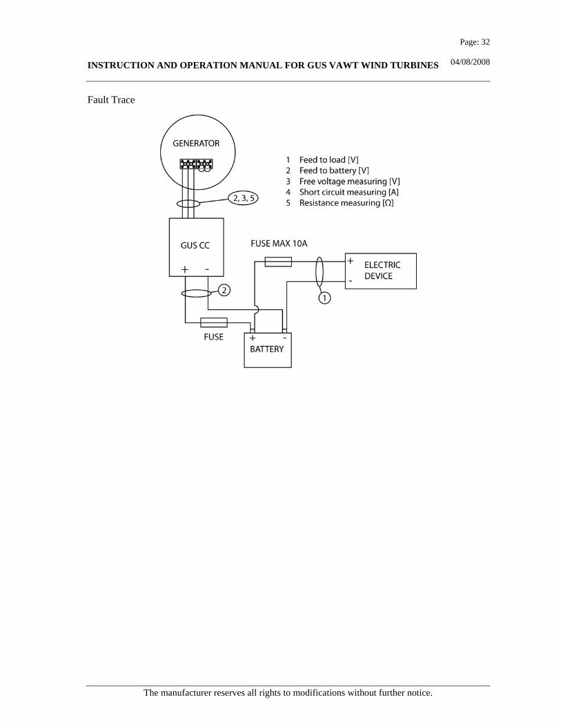
6.3.2 Fault Trace in the Electrical System When the equipment has stopped charging while the turbine is still rotating, the first procedure to do is to check the fuses of the rectifier and charging controller. If the fuse has burned, the + and - wires are in short circuit somewhere, or the poles of the batteries have been connected crosswise. Check all connections. If the fault was not found in the connections, it could be in cabling. Detach the cables from their connections and measure with a standard meter, whether the cable is in short circuit or not. If the cable is damaged, replace it. When the fault has been corrected, replace the fuse. If the fuses are not damaged, but the charging current is still missing, the fault is in coming output. Detach the wires coming from the rectifier and measure if the rectifier is giving any voltage. The next procedure is to measure the phase voltages from the coupler of the wire coming from the generator. These voltages must be equal in size. If that is also correct, the fault is in the rectifier. In this case, please, contact your GUS™ service professional. If the phase voltage is missing, check the connection of the cable to the generator. Check also with a standard meter, whether the cable is undamaged. If not, the faulty part of the cable can be removed and the cable ends can be attached together in a connecting box, which fills all requirements, or, with a cable extension made for that purpose. If the fault was not in the cable, check the phases of the generator by measuring the resistance values from the windings. The turbine must be stopped and the generator detached from the connecting cable before measuring. The resistance values must be equal in every phase. If that is not the case, the winding is damaged. Please, contact your GUS™ service professional.
INSTRUCTION AND OPERATION MANUAL FOR GUS VAWT WIND TURBINES
The manufacturer reserves all rights to modifications without further notice.
Page: 32
04/08/2008
Fault Trace

INSTRUCTION AND OPERATION MANUAL FOR GUS VAWT WIND TURBINES
The manufacturer reserves all rights to modifications without further notice.
Page: 33
04/08/2008
7. SECURITY INSTRUCTIONS AND WARNINGS THESE SYSTEMS (GUS-1,GUS-5 OR GUS-10) PRESENT CHEMICAL, ELECTRICAL AND MECHANICAL CONDITIONS THAT CAN BE LIFE THREATENING.
• HIGH VOLTAGE FROM THE WIND GENERATOR OR THE INVERTER CAN CAUSE INJURY OR ELECTROCUTION.
• A BURN INJURY CAN RESULT FROM AN ELECTRICAL SHORT. • A SEVERE CHEMICAL BURN INCLUDING BLINDING CAN OCCUR FROM A
BATTERY EXPLOSION • OR CONTACT WITH THE SULPHURIC ACID IN A LEAD-ACID BATTERY. • A BODILY INJURY CAN BE EXPERIENCED WHEN IN CONTACT WITH
REVOLVING TURBINE BLADE. DISENGAGE BLADES FROM ROTATING – BEFORE ATTEMPTING TO SERVICE THE GENERATOR OR CONTROLLER. A HIGH VOLTAGE CAN BE PRESENT AT THE GENERATOR OUTPUT TERMINALS WHEN A STRONG WIND ROTATES BLADES AT HIGH SPEED. ALL SYSTEMS SHOULD BE WIRED AND MAINTAINED BY QUALIFIED PERSONNEL. ALWAYS DISCONNECT POWER BEFORE SERVICING A WIND GENERATOR OR CONTROLLER. TOUCHING THE WIRES WITH BARE HANDS OR OTHERWISE WHEN THE CURRENT IS CONNECTED IS ABSOLUTELY FORBIDDEN, AS IT WILL RESULT IN INJURY. WHILE ASSEMBLING AND SERVICING THE TURBINE, THE WIRES COMING FROM THE GENERATOR MUST BE CONNECTED INTO SHORT CIRCUIT BETWEEN THE PHASES U, V, W SO THAT THE ROTATION OF THE TURBINE SLOWS DOWN AND THE VOLTAGES DIMINISH NEAR 0 V. THE ASSEMBLING OR SERVICE OF THE TURBINE MUST NOT BE DONE IN WINDY WEATHER. WHEN WORKING ON THE TURBINE MAST, A SAFETY HARNESS AND ROPE MUST BE USED. IT IS RECOMMENDED WHEN SERVICING A TURBINE HIGH ON A POLE THAT THERE BE AN ADDITIONAL PERSON PLACED AT THE BASE OF THE POLE WHOSE JOB IS TO CONTROL THE SECURITY OF THE PERSON WORKING ON THE POLE. THE ENDS OF THE CABLES COMING FROM THE GENERATOR MUST NEVER BE LEFT UNCOVERED: THE ELECTRIC CIRCUIT MUST ALWAYS BE CLOSED AND WELL PROTECTED. THE VOLTAGE (V) MAY BE HIGHLY DANGEROUS.

INSTRUCTION AND OPERATION MANUAL FOR GUS VAWT WIND TURBINES
The manufacturer reserves all rights to modifications without further notice.
Page: 34
04/08/2008
8. ATTACHMENTS
8.1 Attachment 1 - GUS™ 1

INSTRUCTION AND OPERATION MANUAL FOR GUS VAWT WIND TURBINES
The manufacturer reserves all rights to modifications without further notice.
Page: 35
04/08/2008
8.2 Attachment 2 - GUS™ 5

INSTRUCTION AND OPERATION MANUAL FOR GUS VAWT WIND TURBINES
The manufacturer reserves all rights to modifications without further notice.
Page: 36
04/08/2008
8.3 Attachment 3 - GUS™ 10

INSTRUCTION AND OPERATION MANUAL FOR GUS VAWT WIND TURBINES
The manufacturer reserves all rights to modifications without further notice.
Page: 37
04/08/2008
8.4 Attachment 4 - GUS™5 and GUS™ 10 Spun Concrete Pole Mount
Tightening torque values of the fastening bolts.
M12 = 61.2 ft lbs M16 = 154.9 ft lbs M20 = 298.7 ft lbs M30 = 958.8 ft lbs