gun liner emplacement with an elastomeric material liner emplacement with an elastomeric material by...
TRANSCRIPT
Gun Liner Emplacement With an Elastomeric Material
by William S. de Rosset
ARL-CR-645 April 2010
prepared by
Dynamic Science, Inc. 8433 Black Canyon Hwy.
Phoenix, AZ 85021
under contract
W911QX09-C-0057
Approved for public release; distribution is unlimited.

NOTICES
Disclaimers The findings in this report are not to be construed as an official Department of the Army position unless so designated by other authorized documents. Citation of manufacturer’s or trade names does not constitute an official endorsement or approval of the use thereof. Destroy this report when it is no longer needed. Do not return it to the originator.

Army Research Laboratory Aberdeen Proving Ground, MD 21005-5069
ARL-CR-645 April 2010
Gun Liner Emplacement With an Elastomeric Material
William S. de Rosset
Weapons and Materials Research Directorate, ARL
prepared by
Dynamic Science, Inc. 8433 Black Canyon Hwy.
Phoenix, AZ 85021
under contract
W911QX09-C-0057 Approved for public release; distribution is unlimited.

ii
REPORT DOCUMENTATION PAGE Form Approved OMB No. 0704-0188
Public reporting burden for this collection of information is estimated to average 1 hour per response, including the time for reviewing instructions, searching existing data sources, gathering and maintaining the data needed, and completing and reviewing the collection information. Send comments regarding this burden estimate or any other aspect of this collection of information, including suggestions for reducing the burden, to Department of Defense, Washington Headquarters Services, Directorate for Information Operations and Reports (0704-0188), 1215 Jefferson Davis Highway, Suite 1204, Arlington, VA 22202-4302. Respondents should be aware that notwithstanding any other provision of law, no person shall be subject to any penalty for failing to comply with a collection of information if it does not display a currently valid OMB control number. PLEASE DO NOT RETURN YOUR FORM TO THE ABOVE ADDRESS.
1. REPORT DATE (DD-MM-YYYY)
April 2010 2. REPORT TYPE
Final 3. DATES COVERED (From - To)
October 2006–November 2009 4. TITLE AND SUBTITLE
Gun Liner Emplacement With an Elastomeric Material 5a. CONTRACT NUMBER
5b. GRANT NUMBER
5c. PROGRAM ELEMENT NUMBER
6. AUTHOR(S)
William S. de Rosset 5d. PROJECT NUMBER
AH84 5e. TASK NUMBER
5f. WORK UNIT NUMBER
7. PERFORMING ORGANIZATION NAME(S) AND ADDRESS(ES)
Dynamic Science, Inc. 8433 Black Canyon Hwy. Phoenix, AZ 85021
8. PERFORMING ORGANIZATION REPORT NUMBER
9. SPONSORING/MONITORING AGENCY NAME(S) AND ADDRESS(ES)
U.S. Army Research Laboratory ATTN: RDRL-WMM-F Aberdeen Proving Ground, MD 21005-5069
10. SPONSOR/MONITOR’S ACRONYM(S)
ARL-CR-645
11. SPONSOR/MONITOR'S REPORT NUMBER(S)
12. DISTRIBUTION/AVAILABILITY STATEMENT
Approved for public release; distribution is unlimited.
13. SUPPLEMENTARY NOTES
14. ABSTRACT
The development of a process to emplace a refractory metal liner inside a gun tube is described. The process consists of filling the liner with an elastomeric material and then slipping this arrangement into the gun tube. The ends of the liner are plugged with plastic disks, and pressure is applied to the elastomeric material by a load frame. The original clearance between the liner and gun tube is small, so the action of the pressure expands the liner slightly until it contacts the steel gun tube wall. At that point, greater pressure can produce residual internal stresses within the steel gun tube. Pressures in excess of 250 ksi have been achieved with this simple arrangement. The stresses provide an autofrettage to the steel tube as well as forces retaining the liner inside the tube. Initial efforts have resulted in bond strengths over 3 ksi. In addition, by tailoring the degree of lubrication between the elastomeric material and the liner, a graded autofrettage can be produced in the steel gun tube. 15. SUBJECT TERMS
refractory metal gun liners, elastomeric material, autofrettage, gun tube wear and erosion, erucic acid, bond strength
16. SECURITY CLASSIFICATION OF: 17. LIMITATION OF ABSTRACT
UU
18. NUMBER OF PAGES
38
19a. NAME OF RESPONSIBLE PERSON
William S. de Rosset a. REPORT
Unclassified b. ABSTRACT
Unclassified c. THIS PAGE
Unclassified 19b. TELEPHONE NUMBER (Include area code)
410-306-0816 Standard Form 298 (Rev. 8/98)
Prescribed by ANSI Std. Z39.18

iii
Contents
List of Figures iv
List of Tables v
Acknowledgments vi
1. Introduction 1
2. GLEEM Process 2
3. Experimental 4
3.1 Initial Experiments With 4-in Cylinders .........................................................................4
3.2 The 12-in Cylinder Tests .................................................................................................7
4. Modeling 14
4.1 Strain Analysis of Cylinders Undergoing the GLEEM Process ....................................14
4.2 Bond Strength Estimate .................................................................................................17
5. Summary 24
6. References 25
Distribution List 26
iv
List of Figures
Figure 1. Schematic of GLEEM application...................................................................................2
Figure 2. Schematic cross section of push-out test apparatus. ........................................................5
Figure 3. Modified test assembly showing bolts attaching the retaining ring to the cup platen. .........................................................................................................................................6
Figure 4. Copper liner inner diameter as a function of axial position. ...........................................8
Figure 5. Comparison of inner diameters for tube nos. 1 and 2 after GLEEM process. ..............10
Figure 6. Comparison of hoop strains at gage locations 2 and 3 for tube no. 1. ...........................10
Figure 7. Comparison of hoop strains at gage locations 2 and 3 for tube no. 2. ...........................11
Figure 8. Sectioned ring from copper tube no. 1. .........................................................................12
Figure 9. Inner diameter measurements for Stellite liners no. 1 and 2. ........................................13
Figure 10. Comparison of measured and calculated hoop strains, top gage. ................................16
Figure 11. Comparison of measured and calculated hoop strains, middle gage. ..........................16
Figure 12. Radial stress as a function of distance from the tube axis. ..........................................18
Figure 13. Radial stress as a function of radial position for Rl = 0.4578 in. ................................20
Figure 14. Radial stress vs. axial position for Rl = 0.47 in. ..........................................................21
Figure 15. Radial stress as a function of position for a lined tube that is entirely plastically deformed. .................................................................................................................................22
Figure 16. Residual stress at r = 0.5 in as a function Rs. ..............................................................23
Figure 17. Magnitude of the residual radial stress at r = 0.5 in as a function of the internal pressure (all-steel tube). ...........................................................................................................24

v
List of Tables
Table 1. Bond strength results for 4-in copper liner. ......................................................................5
Table 2. Bond strength results for 4-in Stellite 25 liners ................................................................6
Table 3. Bond strength results for 12-in copper liner .....................................................................8
Table 4. Bond strengths for 12-in copper tube no. 1. ...................................................................11
Table 5. Bond-strength data. .........................................................................................................13
Table 6. Composite tube characteristics. ......................................................................................17
vi
Acknowledgments
The author acknowledges the substantial contribution to this work made by Dr. Robert Carter and David Gray. Dr. Carter was the program lead, and Mr. Gray conducted the laboratory work. The author is also grateful for the help of Matthew Trexler, who provided a cold-sprayed pure tantalum liner for our use. Thanks also go to Suveen Mathaudhu for seeing that the tantalum liner was properly heat treated. Finally, thanks go to Eric Klier who suggested the use of erucic acid as a high-pressure lubricant.

1
1. Introduction
The U.S. Army uses liners or coatings in many of its guns currently in service. This includes a chrome coating in the M256 main tank armament, a nitride surface treatment in the M242 Bushmaster medium caliber canon, and a Stellite 21 liner in the M2 machine gun. The liners or coatings increase the barrel wear life of those guns by protecting them against the effects of hot propellant gasses. Chrome coatings are applied by electroplating the bore of the gun, whereas the Stellite liner is mechanically emplaced in the gun tube. Recent advances have raised the possibility of explosively bonding liners to gun tubes (1, 2). In addition, a program is being conducted by Benet Laboratories to develop a tantalum sputtering process to line the M256 main tank gun. The choice of liner or coating material, as well as the means by which the coating or liner is applied, is highly dependent on the cost savings achieved through extended barrel wear life.
A new idea that has potential to apply liners to gun tubes economically has been proposed in a recent patent application (3). The idea, whose genesis was in pressure testing of ceramic tubes (4), is to use an elastomeric material to apply pressure to the liner and force a mechanical bond between it and the gun bore. The term “Gun Liner Emplacement by Elastomeric Material,” or GLEEM, has been coined for this process. GLEEM is different from application of hydraulics to achieve the same type of bond in that no expensive high-pressure seals are required with the solid elastomeric material. The bond that is produced with the elastomeric material is based on frictional forces between the liner and gun tube. The bond strength with the elastomeric material is much lower than that achieved by explosive bonding. The minimum bond strength that is required for any specific application has not been thoroughly investigated, although an initial examination of the bond strength necessary for the machine gun liner has been carried out (5).
GLEEM also produces a controlled amount of autofrettage in a gun barrel. That is, the application of pressure to the gun tube bore surface can produce plastic deformation and a residual stress near the surface that strengthens the gun tube and allows higher operating pressures and a longer fatigue life. The same effect is produced with explosive bonding, although to a higher degree because of the higher pressures.
Experimental and theoretical work has been performed to advance GLEEM technology. This report details the initial efforts to address several issues involved with the GLEEM process. Copper was chosen as the first material to use with GLEEM because of availability and expense. Several refractory metals were used subsequently. The range of pressure that was possible with the current seals was explored. Bond strengths were measured as well as the amount of plastic strain imparted to the composite tube. The next section provides a general description of the GLEEM process. This is followed by the experiments that helped to develop the GLEEM

2
process parameters and techniques. Section 4 presents simple modeling efforts used to estimate the external hoop strains and the residual radial stress for a given load. Section 5 summarizes the progress to date made in the development of the process.
2. GLEEM Process
Figure 1 is a schematic of the basic setup for the GLEEM process. The object in the upper left corner of this figure is the item to be lined, generally a thick-walled steel gun tube capable of withstanding high pressure. To the right is a sectional view of the liner, gun tube, and the parts necessary to apply the GLEEM process. In preparation for liner emplacement, the gun tube must be reamed to the appropriate inner diameter. In some instances, it might be necessary to roughen the inner bore of the gun tube in order to increase the mechanical interference between the liner and gun tube and consequently increase the bond strength.
Figure 1. Schematic of GLEEM application.
Gun Tube
Piston
Base Plate
Sealing Disks
Elastomer
Liner

3
Into this gun tube is slipped a thin-walled tube of the selected liner material. The tolerances on the outer diameter of the liner tube are such that there is no binding between the gun tube and liner as the liner is put into place. In most instances, the liner outer diameter is 0.004–0.006 in less than the gun tube inner diameter. However, for very long gun tubes where there is the possibility for variation in the inner bore diameter and deviation of the gun tube center line from a straight line, the tolerances on the liner tube might be relaxed. The thickness of the liner must take into account whether lands and grooves will be machined into the liner. After the GLEEM process is applied to the liner, final machining will be performed to achieve the required inner bore diameter for the gun. Choice of initial liner thickness must therefore take into account some radial expansion of the liner and gun tube. In an actual manufacturing process, the liner may be longer than the gun tube, depending on whether a blank or near-net-shape gun tube is being lined. For the work described in this report, the liner was generally the same length as the steel tube.
The elastomeric material is any suitable elastic polymer with a high (~0.5) Poissons ratio. For this particular work, Dow Corning Silastic* J RTV was chosen. This material is made by combining 10 parts of a liquid base with 1 part of a hardening agent to produce viscous liquid that sets up in 24 h. The viscous liquid is poured into the liner and allowed to gel into a solid plug of material. The elastomeric plug is made such that it is slightly shorter than the liner. The assembly is cooled in a freezer at –22 °F to allow shrinkage of the plug and its removal from the liner. A lubricating material is then applied to the plug, which is then cooled and re-inserted into the liner. If not already in place, the liner is inserted into the gun tube.
Sealing disks made of Nylon† are then placed inside ends of the liner. The assembly is mounted on a base plate and put into a device capable of applying pressure to one of the disks through a piston. The pressure equipment used in this work was an MTS test machine. After the maximum load for bonding has been achieved, the assembly is removed from the pressure device and cooled to allow removal of the elastomeric plug.
To calculate the internal pressures generated from the GLEEM process, an elasticity analysis is used to derive the relation from axial force and displacement to internal pressure (4). By using Hooke’s law expression for axial strain εz for cylindrical coordinates,
1– ( )z z rε =
E
, (1)
and the following relations: r = -Pi, and r = , for solid cylinders under compression, the expression can be rearranged to:
*Dow Corning Silastic is a registered trademark of Dow Corning, Midland, MI. †Nylon is a trademark of DuPont Corp., Wilmington, DE.

4
2z zE
Pi
. (2)
In these expressions, Pi is the internal pressure, E is the Young’s modulus for the rubber, is the Poisson’s ratio, σ is a stress component, and r, , and z refer to the radial, hoop, and axial directions, respectively. Given that high pressure (>500 MPa) will be necessary to plastically deform the liner and gun tube, the Young’s modulus for the rubber is low (5.7 MPa), and the Poisson’s ratio is nearly 0.5, the equation can be simplified further:
zPi . (3)
3. Experimental
3.1 Initial Experiments With 4-in Cylinders
The first experiments that demonstrated GLEEM used inexpensive and readily available materials. A 4-in copper tube with an outer diameter of 1.14 in and a wall thickness of 0.065 in was placed inside a 4-in long steel tube. The inner diameter of the steel tube was just large enough to accommodate the copper tube. The outer diameter of the steel tube was 3 in. The elastomeric plug was made for the experiment in the manner described in the previous discussion. After placing 0.5-in-thick sealing disks into the liner, the copper-lined steel tube was then placed into the MTS test machine. A cross-head speed of 0.1 in/min allowed a slow compression of the plug. At less than 50,000 lb load the sealing disks were ruptured. Portions of the plug were ejected from the tube. The remainder of the plug was removed by the process just described.
The bond strength of the copper liner was measured by a push-out test (6). Three 0.2-in-thick slices were sectioned from the copper-lined steel tube. A hardened steel pusher plug was used to push the copper liners out of each slice. A schematic of the test fixture is shown in figure 2. The value of the steel pusher plug outer diameter (D1) was 1.09 in, and the value of the inner diameter (D2) was 1.00 in.
The bond strength is due to the residual radial stress and the friction between the liner and gun tube. As such, it is not a true mechanical bond, nor is it a metallurgical bond. The residual stress can be approximated by a simple analytical approach, shown in section 4. Assuming a reasonable value for the coefficient of friction, the bond strength can be estimated.
The maximum load that each slice of liner sustained is shown in table 1 along with the calculated bond shear strength. The bond shear strength is calculated by dividing the maximum load by the contact area of the liner with the gun tube.

5
Figure 2. Schematic cross section of push-out test apparatus.
Table 1. Bond strength results for 4-in copper liner.
Sample
Maximum Load
(lb)
Calculated Bond Shear Strength
(psi) RC1 506 706 RC2 541 755 RC3 600 838
The average calculated bond strength (766 psi) is comparable to that calculated from push-out tests on a Stellite 21 liner in an M2 machine gun (776 psi, reference 5). These results were sufficiently encouraging to proceed with using Stellite 25 as the liner material.
In a similar manner as with the copper liner, a 4-in Stellite 25 liner was slipped into a 4-in steel tube. The GLEEM process was applied to bond the Stellite 25 to the steel. The test setup was slightly different from the first one. For the Stellite-lined gun tube, the flat base plate was replaced with a cup platen. The steel tube fit inside the cup platen which helped to stabilize the test assembly. As before, the sealing disks ruptured at a load <50,000 lb. After the plug was removed from the Stellite-lined tube, three slices were taken from the central portion of the composite tube. The test samples are labeled RS1, RS2, and RS3. The data for the push-out tests are shown in table 2.
A second Stellite 25 liner was bonded to a steel tube using the GLEEM process. The test fixture was modified in an attempt to reach a higher load. The new fixture is shown in figure 3. Here, the cup platen is attached to a retaining ring by four long bolts. The retaining ring prevents the plug material from pushing the steel tube upwards as the elastomeric material is extruded past the lower sealing disk. The bond strength results for three slices taken from this test article, labeled RS4, RS5, and RS6, are shown in table 2. A maximum load of 52,000 lb was achieved during the GLEEM process, leading to a higher bond strength for the second Stellite 25 liner.
D1
D2
Base Plate
Pusher Plug Gun Tube
Liner

6
Table 2. Bond strength results for 4-in Stellite 25 liners.
Sample
Slice Thickness
(in)
Outer Diameter of Liner
(in)
Maximum Load
(lb)
Calculated Bond Shear Strength
(psi) RS1 0.209 1.021 541.5 808 RS2 0.203 1.020 599.6 922 RS3 0.202 1.020 500.0 772 RS4 0.202 1.013 909.0 1414 RS5 0.203 1.018 1063 1637 RS6 0.200 1.019 573.0 894
Figure 3. Modified test assembly showing bolts attaching the retaining ring to the cup platen.
The seals in the test of the second Stellite did not fail. In order to determine the maximum load possible with this arrangement, a third Stellite-lined steel tube was made using a higher-strength steel cylinder. Previous steel tubes had a hardness of HRC 17. This particular steel tube was heat treated to a hardness of HRC 34. Care was taken to make the seals as tight fitting as possible. A million-pound load frame was used to apply pressure to the test arrangement. At a load of 158,749 lb, the seals failed with a loud pop. The radius of the elastomeric plug was 0.42 in, so the calculated pressure was 301.3 ksi. Extensive plastic deformation of the steel cylinder was observed.
Cup Platen
Retaining Ring
MTS Crosshead
Steel Barrel
Bolt
7
The third liner material examined with the GLEEM process was pure tantalum. An 11-in tube was produced by the cold-spray process (7). The outer diameter was 0.925 in and the wall thickness varied from 0.091 to 0.092 in. The cold-spry process leaves the material in a hardened condition, and consequently the tantalum tube had to be annealed. The tube was sent to H. C. Starck where it was annealed at 1250 °C for 90 min in a vacuum (10–6 torr) furnace (8). When the tube was returned to the U.S. Army Research Laboratory, two small cracks were observed in the tube. An attempt was made to bond a 4-in section of the tube with the GLEEM process. The load was taken to 90,000 lb and cycled ten times. During the process, the top nylon seal was partially extruded past the steel piston, but the pressure on the elastomeric material was maintained. When the steel cylinder with tantalum liner was removed from the load machine, it was observed that the fractures in the tantalum had opened up. In sectioning the tube into thin slices for the bond strength tests, the liner shifted inside the steel cylinder, indicating that there was no bond. The final measured inner diameter of the liner was 0.768 in, representing a 3.7% plastic strain in the tantalum had it remained intact.
Later in the development process, a 4-in-long tube of BioDur CCM* was pressed into a steel tube using GLEEM. BioDur CCM is a chrome-cobalt alloy that is used for medical implants. The tube was machined from a solid bar of metal. The load frame was programmed to ramp up to 90,000 lb. However, at approximately 79,000 lb of load, the seals broke. This was likely due to the relatively large plastic strain that was achieved (3.4 ×10⁻³ hoop strain). After removing the elastomeric material from the tube, the inner diameter of the BioDur CCM tube was measured. The tube had sustained ~2% plastic strain (radial expansion) midway between the ends of the tube. In preparation for a bond strength determination, a thin section of the liner-tube combination was sectioned near the point of maximum radial expansion using an electro-discharge machine. During this process, the liner fell out of the cut section. Clearly, the bond strength was zero for this sample. This result was unexpected and has not been fully explained at this time.
3.2 The 12-in Cylinder Tests
The next step in the development of GLEEM technology was to scale the process to 12-in tubes. As before, copper was chosen as the first liner material. The same arrangement of cup platen and bolts as shown in figure 3 was used. A small tolerance on the diameter of the sealing disks was used to provide a very tight fit when they were placed inside the copper liner. In addition, five strain gages were attached to the outside surface of the steel cylinder. Three strain gages (1, 2, and 3) were located 4, 6, and 8 in from the top of the steel cylinder. The other two strain gages (4 and 5) were located 180° from gages 2 and 3 at 6 and 8 in, respectively.
*BioDur CCM is a trademark of Carpenter Technology, Wyomissing, PA.

8
The crosshead speed of the MTS load frame was set to 0.25 in/min. After about 10 min, the load reached 80,000 lb, and the seals did not fail. The total displacement of the crosshead was 2.39 in. The crosshead was held at this position and the load was observed to drop to 76,000 lb in 8 s.
The sample was then removed from the MTS machine and the elastomer plug removed. The steel cylinder was sectioned to provide samples that were used to measure the bond strength. Four such tests were made, and the results are shown in table 3. The axial location refers to the distance from the top of the steel cylinder.
Table 3. Bond strength results for 12-in copper liner.
Sample
Slice Thickness
(in)
Outer LinerDiameter
(in)
MaximumLoad (lb)
Axial Location
(in)
Calculated Bond Strength
(psi) RC4 0.205 1.176 1459.5 4.3 1926 RC5 0.208 1.172 1582.2 6.0 2067 RC6 0.200 1.142 223.3 8.0 311 RC7 0.200 1.154 214.0 10.1 295
The inner diameter of the copper liner was measured as a function of axial position. The results are shown in figure 4. In this plot, the top end of the elastomer plug (nylon seal – elastomer plug interface) was located between 2.39 and 2.89 in from the top of the steel tube at the end of the test. The fact that the inner diameter of the copper tube decreased from an axial position of 4 in to the end of the tube indicated that friction could be a large problem for long cylinders.
Axial Position, in
0 2 4 6 8 10 12 14
Inne
r D
iam
ete
r, in
1.00
1.02
1.04
1.06
1.08
1.10
Figure 4. Copper liner inner diameter as a function of axial position.
9
To address this problem, several experiments were carried out with 4-in tubes. Two different approaches were taken to reduce friction: (1) use of a Teflon* sleeve around the elastomer plug and (2) use of erucic acid as a lubricant between the elastomer plug and the tube wall. (The second approach was suggested by Klier [9].) The second approach appeared to reduce the friction to a noticeable degree. In addition, application of the erucic acid was more straightforward than use of the Teflon sleeve.
Two more 12-in copper tubes and steel cylinders were prepared for the next series of tests. Hoop strain gages were attached to the steel cylinder outer surface at 3, 6, and 10 in from the top of the cylinder. Erucic acid was applied to the elastomer plug before it was cooled and inserted into the copper tube. Dimensions of the nylon seals were the same as used previously.
The test procedures for the next two copper-lined tubes were considered different enough from those used for the first tube that numbering of the tubes was restarted. Thus, the next copper-lined tube was labeled copper tube no. 1. A crosshead speed of 0.1 in/min was used. When the load reached 80,000 lb, the displacement was held constant for 3 min. During this time, the load decreased to about 72,000 lb. The load was then increased to 80,000 lb, and the crosshead displacement was held constant. The process of cycling the load continued for several more times, and then the equipment was left overnight under pressure. The next morning the equipment was still in operation. However, after several hours the upper seal broke and the test was halted.
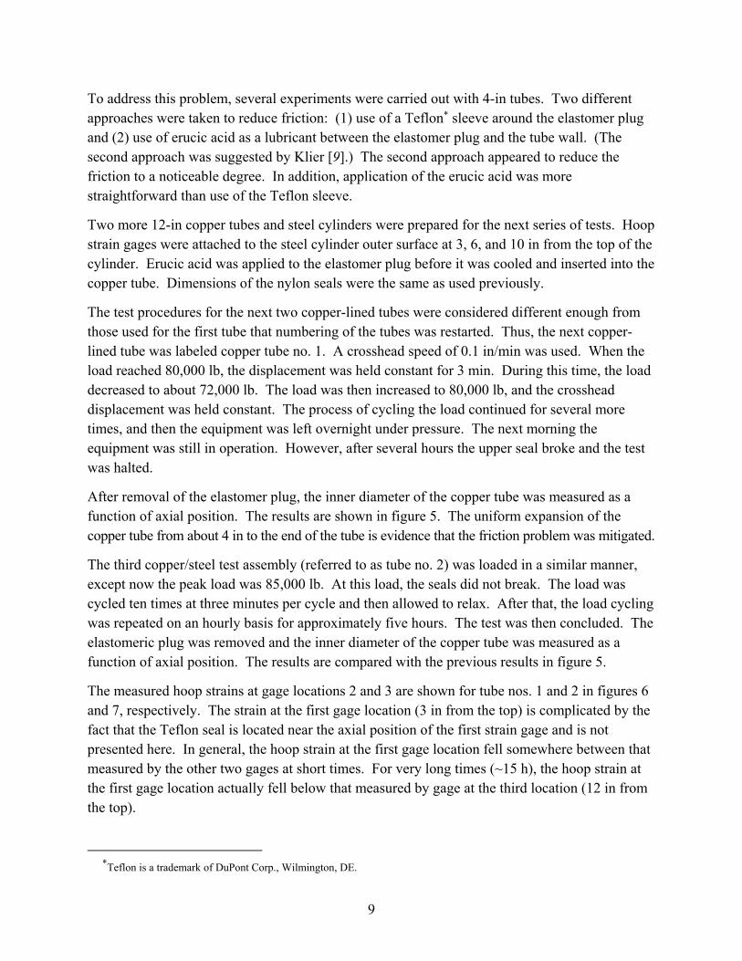
After removal of the elastomer plug, the inner diameter of the copper tube was measured as a function of axial position. The results are shown in figure 5. The uniform expansion of the copper tube from about 4 in to the end of the tube is evidence that the friction problem was mitigated.
The third copper/steel test assembly (referred to as tube no. 2) was loaded in a similar manner, except now the peak load was 85,000 lb. At this load, the seals did not break. The load was cycled ten times at three minutes per cycle and then allowed to relax. After that, the load cycling was repeated on an hourly basis for approximately five hours. The test was then concluded. The elastomeric plug was removed and the inner diameter of the copper tube was measured as a function of axial position. The results are compared with the previous results in figure 5.
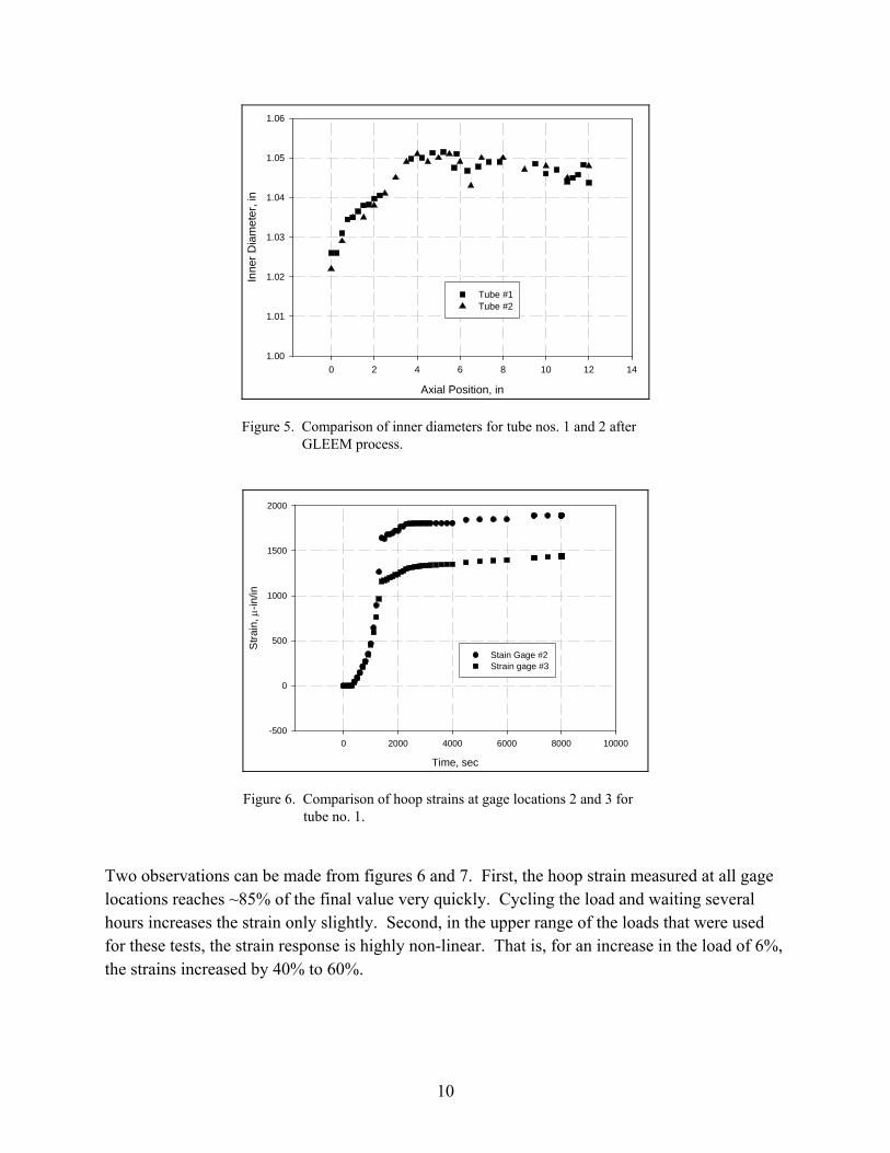
The measured hoop strains at gage locations 2 and 3 are shown for tube nos. 1 and 2 in figures 6 and 7, respectively. The strain at the first gage location (3 in from the top) is complicated by the fact that the Teflon seal is located near the axial position of the first strain gage and is not presented here. In general, the hoop strain at the first gage location fell somewhere between that measured by the other two gages at short times. For very long times (~15 h), the hoop strain at the first gage location actually fell below that measured by gage at the third location (12 in from the top).
*Teflon is a trademark of DuPont Corp., Wilmington, DE.
10
Axial Position, in
0 2 4 6 8 10 12 14
Inne
r D
iam
eter
, in
1.00
1.01
1.02
1.03
1.04
1.05
1.06
Tube #1Tube #2
Figure 5. Comparison of inner diameters for tube nos. 1 and 2 after GLEEM process.
Time, sec
0 2000 4000 6000 8000 10000
Str
ain,
-i
n/in
-500
0
500
1000
1500
2000
Stain Gage #2Strain gage #3
Figure 6. Comparison of hoop strains at gage locations 2 and 3 for tube no. 1.
Two observations can be made from figures 6 and 7. First, the hoop strain measured at all gage locations reaches ~85% of the final value very quickly. Cycling the load and waiting several hours increases the strain only slightly. Second, in the upper range of the loads that were used for these tests, the strain response is highly non-linear. That is, for an increase in the load of 6%, the strains increased by 40% to 60%.

11
Time, sec
0 2000 4000 6000 8000 10000
Str
ain,
-i
n/in
-500
0
500
1000
1500
2000
2500
3000
3500
Strain Gage #2Strain Gage #3
Figure 7. Comparison of hoop strains at gage locations 2 and 3 for tube no. 2.
The bond strength at three locations was measured for tube no. 1. The results are shown in table 4. Sample numbering continues from the previous tests. The results indicate that a substantial increase in bond strength has been achieved by using erucic acid as the lubricant between the elastomer plug and the copper liner. In particular, the bond strength at the bottom end of the composite tube has increased from 300 psi to over 2000 psi.
Table 4. Bond strengths for 12-in copper tube no. 1.
Sample
Slice Thickness
(in)
Outer LinerDiameter
(in)
MaximumLoad (lb)
Axial Position
(in)
Calculated Bond Strength
(psi) RC8 0.198 1.141 2541 3.9 3580 RC9 0.203 1.141 2663 5.8 3660
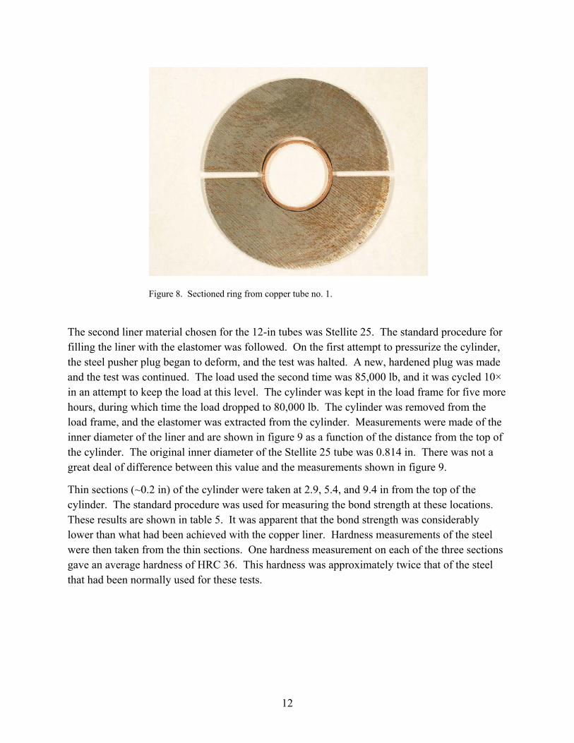
RC10 0.203 1.138 1517 9.9 2090 A fourth slice was cut from copper tube no. 1 near the position where the bond strength was measured to be 3660 psi. The cut was made with an electro-spark discharge machine (EDM). This slice was then cut with an EDM along a diameter of the ring. As soon as the EDM wire cut through the copper liner, the stress on the liner was released. The EDM continued to cut through the copper liner, and the liner dropped out of the range of the cutting wire. The cut was continued until the steel ring was cut in two. While the inner surface of the copper ring was smooth, the outer surface (formerly in contact with the steel tube) took on the surface texture of the steel tube. See figure 8 for a reassembly of the parts.
12
Figure 8. Sectioned ring from copper tube no. 1.
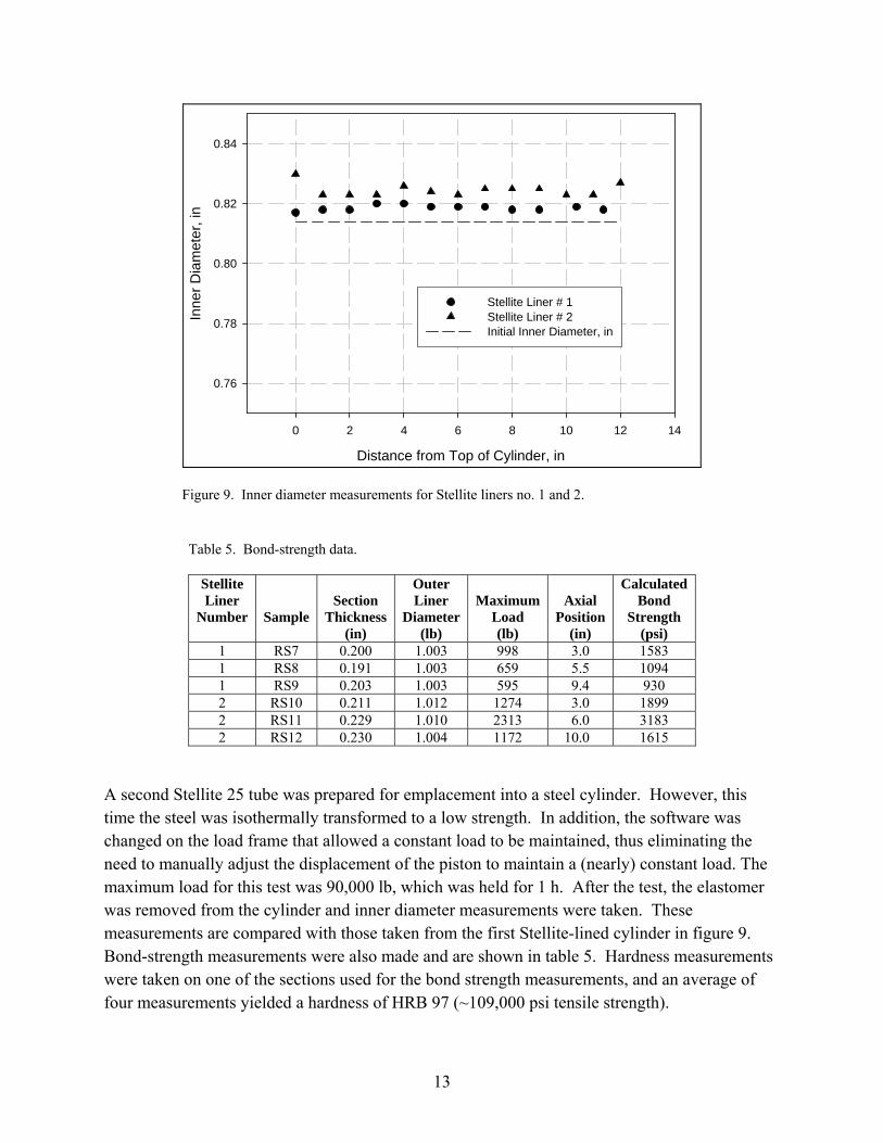
The second liner material chosen for the 12-in tubes was Stellite 25. The standard procedure for filling the liner with the elastomer was followed. On the first attempt to pressurize the cylinder, the steel pusher plug began to deform, and the test was halted. A new, hardened plug was made and the test was continued. The load used the second time was 85,000 lb, and it was cycled 10× in an attempt to keep the load at this level. The cylinder was kept in the load frame for five more hours, during which time the load dropped to 80,000 lb. The cylinder was removed from the load frame, and the elastomer was extracted from the cylinder. Measurements were made of the inner diameter of the liner and are shown in figure 9 as a function of the distance from the top of the cylinder. The original inner diameter of the Stellite 25 tube was 0.814 in. There was not a great deal of difference between this value and the measurements shown in figure 9.
Thin sections (~0.2 in) of the cylinder were taken at 2.9, 5.4, and 9.4 in from the top of the cylinder. The standard procedure was used for measuring the bond strength at these locations. These results are shown in table 5. It was apparent that the bond strength was considerably lower than what had been achieved with the copper liner. Hardness measurements of the steel were then taken from the thin sections. One hardness measurement on each of the three sections gave an average hardness of HRC 36. This hardness was approximately twice that of the steel that had been normally used for these tests.
13
Distance from Top of Cylinder, in
0 2 4 6 8 10 12 14
Inne
r D
iam
eter
, in
0.76
0.78
0.80
0.82
0.84
Stellite Liner # 1Stellite Liner # 2Initial Inner Diameter, in
Figure 9. Inner diameter measurements for Stellite liners no. 1 and 2.
Table 5. Bond-strength data.
Stellite Liner
Number
Sample
Section
Thickness(in)
Outer Liner
Diameter(lb)
Maximum
Load (lb)
Axial
Position(in)
Calculated Bond
Strength (psi)
1 RS7 0.200 1.003 998 3.0 1583 1 RS8 0.191 1.003 659 5.5 1094 1 RS9 0.203 1.003 595 9.4 930 2 RS10 0.211 1.012 1274 3.0 1899 2 RS11 0.229 1.010 2313 6.0 3183 2 RS12 0.230 1.004 1172 10.0 1615
A second Stellite 25 tube was prepared for emplacement into a steel cylinder. However, this time the steel was isothermally transformed to a low strength. In addition, the software was changed on the load frame that allowed a constant load to be maintained, thus eliminating the need to manually adjust the displacement of the piston to maintain a (nearly) constant load. The maximum load for this test was 90,000 lb, which was held for 1 h. After the test, the elastomer was removed from the cylinder and inner diameter measurements were taken. These measurements are compared with those taken from the first Stellite-lined cylinder in figure 9. Bond-strength measurements were also made and are shown in table 5. Hardness measurements were taken on one of the sections used for the bond strength measurements, and an average of four measurements yielded a hardness of HRB 97 (~109,000 psi tensile strength).

14
4. Modeling
Modeling the GLEEM process can be as complicated as desired. For instance, a finite element structures code can be used to predict the elastic-plastic response of the metal tube and liner to the applied load. The elastomeric material can be modeled as visco-elastic. The effects of friction between the elastomeric material and liner can also be accounted for. The particular geometry of a given experiment can be represented. All these different effects and material models tend to make the calculation complicated. This has been found to be the case in attempts to model the GLEEM process with the ANSYS* code. While progress has been made in making the calculations as complete as possible, additional work needs to be done. The final results of this effort will be included in a future report.
In lieu of a precise calculation, approximations can be made and standard elasticity theory invoked to compare the measured hoop strain with prediction. In addition, use of plasticity theory can provide an estimate of the frictional bond strength produced by the residual radial stress. These calculations are presented in the following sections.
4.1 Strain Analysis of Cylinders Undergoing the GLEEM Process
Measurements of hoop strain and applied load have been taken on 4340 steel cylinders while they have been undergoing the GLEEM process. Elasticity theory can be applied to predict the amount of strain for a given load, given a few basic assumptions or conditions. The first is that the load on the cylinder does not cause it to deform plastically. The one instance where the cylinder appeared to undergo only elastic deformation was with the 12-in steel cylinder containing a Stellite 25 liner. In this case, the steel used was in a harder condition than normally used. Little or no expansion of the inside diameter of the liner was observed after the test. Hoop strains were measured at distances of 3, 6, and 9 in from the top of the steel cylinder.
A major assumption that will be made is that the pressure is uniform within the cylinder. This assumption will be in error by the degree which friction inhibits the elastomeric material from moving within the liner to equalize the pressure. A lubricant (erucic acid) was used to reduce this friction. However, it is expected that some friction remained. The internal pressure will be calculated as the load produced by the load frame (Instron machine) divided by the area enclosed by a cross section of the liner (see equation 3).
The tangential or hoop strain εt for a cylinder is given in terms of the radial displacement u as
rut / , (4)
*ANSYS is a registered trademark of SAS Institute, Inc., Cary, NC.
15
where r is the distance from the cylinder axis. For an internally pressurized cylinder, the differential equation relating u to r is
01
22
2
r
u
dr
du
rdr
ud . (5)
The general solution to this equation is
r
CrCu 2
1 . (6)
The constants C1 and C2 are determined by the boundary conditions. In this particular case, the internal pressure is taken as Pi and the external pressure is set to 0. The constants are then determined to be
22
2
1
1
ab
Pia
EC
(7)
and
22
22
2
1
ab
Piba
EC
. (8)
Here, E is Young’s modulus, ν is Poisson’s ratio, a is the inner radius of the cylinder, and b is the outer radius of the cylinder. Substituting these expressions into equation 6 and setting r = b to find the radial displacement on the outer surface of the cylinder, we get
bab
Piba
Eab
bPia
Eu
11122
22
22
2
. (9)
Setting r = b in equation 4 and substituting for u, we get
22
22
ab
Pia
Et
. (10)
We have assumed that the liner is thin enough that the difference in elastic properties between Stellite and steel can be neglected. Values of the parameters used in these calculations are as follows:
a = 0.41 in; b = 1.5 in; E = 29700 ksi. (11)
The exact modulus for the 4340 steel used in the GLEEM process is not known. The value of 29,700 ksi was taken from several sources on the web (see, for instance, reference 9).

16
If frictional effects reduce the internal pressure as the distance from the piston increases, then it is reasonable to expect that the gage at the 3-in location would provide the best agreement between the measurements and calculation of hoop strain. This comparison is shown in figure 10. As seen in the figure, the agreement is perhaps better than should be expected, given all the assumptions.
Pressure, ksi
0 20 40 60 80 100 120 140 160 180
Hoo
p S
tra
in
0.0000
0.0002
0.0004
0.0006
0.0008
0.0010
MeasuredCalculated
Figure 10. Comparison of measured and calculated hoop strains, top gage.
To examine the effects of friction between the elastomer and liner, the same comparison can be made with gages further away from the piston. Figure 11 shows this comparison for the second gage, located 6 in from the top of the cylinder.
Pressure, ksi
0 20 40 60 80 100 120 140 160 180
Hoo
p S
trai
n
0.0000
0.0002
0.0004
0.0006
0.0008
MeasuredCalculated
Figure 11. Comparison of measured and calculated hoop strains, middle gage.
17
It can be seen that the hoop strain is in fair agreement at the lower strains but deviates when the measured pressure exceeds 40 ksi. It is assumed that at that point the frictional forces begin to prevent the axial load from being distributed equally along the length of the liner. Thus, the calculated hoop strain should be larger than the measured hoop strain.
To get a closer agreement between the measured and calculated hoop strain, the finite element code would need to be used.
4.2 Bond Strength Estimate
The bond formed between the liner and gun tube depends on the residual radial stress and the coefficient of friction between the liner and gun tube. The residual radial stress due to an internal pressure can be calculated with standard formulas, and the coefficient of friction can be estimated. While formulas for residual stress can be found in most basic mechanics texts, we have made particular use of reference 10. We take as our example the second Stellite-lined steel cylinder discussed in section 3.2. As before, we use the notation a = liner inner radius. However, now b = liner outer radius, and c = gun tube outer radius. For these calculations we assume elastic-perfectly plastic material behavior of both the Stellite and 4340 steel. The relevant dimensions and properties are given in table 6.
Table 6. Composite tube characteristics.
Material
Tube ID
(in)
Tube OD
(in)
Yield Strength
(psi) Stellite 25 0.814 1.00 130,000 4340 steel 1.00 3.00 109,000
The yield strength of the 4340 steel is taken from a conversion of the hardness measurements made on a section of this steel cylinder. The yield strength of the Stellite 25 is taken from reference 9. The dimensions are those before the GLEEM process is applied to the composite cylinder.
For an internal pressure Pi that is low enough that the yield strength of the steel is not reached, the solution for the radial stress, σr, is simply the elastic solution:
)/1(
122
2rc
W
Pir
, (12)
where
6855.3407./5.1/ acW . (13)
Thus, we get
)/25.21)(583.12/( 2rPir (14)

18
as the radial stress. This function is plotted in figure 12 for several values of internal pressure. However, it is likely that the Stellite has already yielded before the internal pressure reaches 160 ksi. Note that the radial stress in the Stellite-steel composite tube as a function of the radius does not depend on any Stellite material properties. In addition, compressive stresses are negative, while tensile stresses are positive.
Radial Position, in
0.2 0.4 0.6 0.8 1.0 1.2 1.4 1.6
Rad
ial S
tre
ss, k
si
-180
-160
-140
-120
-100
-80
-60
-40
-20
0
40 ksi Internal Pressure60 ksi Internal Pressure160 ksi Internal Pressure
Figure 12. Radial stress as a function of distance from the tube axis.
In order to find the pressure at which the Stellite first yields, we make use of the Tresca yield criterion for r = a:
)2/()1( 22 WWPi y , (15)
where σy is the yield strength. In our particular case, we get
130000(13.5829 1) /(2*13.5829) 60215Pi psi. (16)
Thus, at an internal pressure of ~60 ksi, the Stellite liner begins to yield.
We can make a similar calculation just for the steel tube. In this case, q is the stress exerted by the liner on the steel. As the internal pressure is raised from 60 ksi, the plastic zone in the Stellite will increase until it reaches the liner-gun tube interface. At some point before then, it may be that the steel yields. To find this point, we can make a similar calculation of the stress produced by the liner on the gun tube to yield the steel. In this case,

19
35./5.1 W , (17)
so that from equation 15, we get
109000(9 1) /(2*9) 48444q psi. (18)
Here, we have used the relevant dimensions for the steel tube to determine the value of W. Figure 12 confirms that for an internal pressure of 60 ksi, the radial stress at r = 0.5 in is below 48 ksi and the steel has not yielded.
We next calculate the stress in the Stellite liner as the internal pressure is increased above 60 ksi. Part of the liner will have yielded, and part will still be elastic. We first look at the problem as a cylinder with three concentric portions. The first (inner) portion from 0 .407 in < r < Rl is plastic; here Rl is the outer radius of the plastic zone in the Stellite liner. The next portion goes from Rl to 0.5 in. This is the elastic portion of the liner. Note that we have neglected a small amount of increase in the liner radius due to the internal pressure. From 0.5 to 1.5 in is the elastic portion of the steel gun tube.
The pressure (radial stress) at the elastic/plastic interface will simply be the stress needed to yield a tube with inner radius of Rl. (We use the yield strength of the liner material here.)
2 2 2 2(( / ) 1) /(2( / ) ) 130((1.5 / ) 1) /(2(1.5 / ) )r r R y c Rl c Rl Rl Rl ksi. (19)
For the very slight increase in Rl, the value of σr goes down.
The stress in the elastic portion of the composite tube can then be calculated using equation 15 as
2
22
(1 ( / ) )2re y
Rlc r
c , (20)
where σre is the elastic radial stress. Note that in this equation, Rl < r < c. A sample plot for R = 0.4578 in is shown in figure 13. The value of σre at r = 0.5 in is 48436 psi, close to the calculated pressure (radial stress) to cause yielding in the steel gun tube. Thus, when the plastic zone in the liner reaches 0.4578 in, the pressure (radial stress) is sufficient to begin to plastically deform the steel. In this case, a part of the liner is still elastic, and any increases in the internal pressure will increase the plastic zones in both the liner and the steel.
The radial stress in the plastic portion of the liner can be calculated from equation 35, reference 10:
2 2 2ln( ) ( ) /(2 )rp y yr / l c Rl c . (21)
The radial stress for 0.407 in < r < 0.4578 in is also shown in figure 13. The minimum internal pressure needed to yield the steel cylinder is 74.2 ksi.

20
Radial Position, in
0.2 0.4 0.6 0.8 1.0 1.2 1.4 1.6
Rad
ial S
tres
s, k
si
-80
-60
-40
-20
0
Rl = 0.4578 in
Figure 13. Radial stress as a function of radial position for Rl = 0.4578 in.
We now increase the internal pressure above 74.2 ksi so that some of the steel tube yields. For instance, we can calculate the radial stress for Rs = 0.47 in. From this point forward, we will distinguish between the radius of the plastic zone in the liner, Rl, and the radius of the plastic zone in the steel, Rs. For the liner, we can calculate the radial stress for both the plastic (σrp) and elastic (σre) portions:
2 2 2130ln( / 0.46) 130(1.5 0.46 ) /(2(1.5 ) 130ln( / 0.46) 58.887rp r r ksi (22)
and
2 2
2 2
130(0.46 ) 1.5(1 )
2(1.5 )re r ksi (23)
for
5.0407.0 r . (24)
At r = 0.5 in, the elastic radial stress is calculated to be –51.05 ksi. We can find Rs by adjusting its value until the plastic solution for the steel tube matches this value at r = 0.5 in.
The plastic solution for the steel tube is
)5.1(2/()5.1(103)/ln(109 222 RsRsrrp ksi. (25)
21
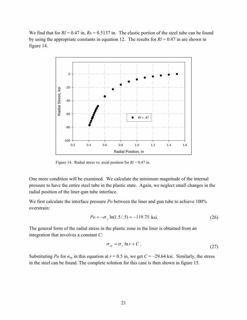
We find that for Rl = 0.47 in, Rs = 0.5137 in. The elastic portion of the steel tube can be found by using the appropriate constants in equation 12. The results for Rl = 0.47 in are shown in figure 14.
Radial Position, in
0.2 0.4 0.6 0.8 1.0 1.2 1.4 1.6
Rad
ial S
tre
ss, k
si
-100
-80
-60
-40
-20
0
Rl = .47
Figure 14. Radial stress vs. axial position for Rl = 0.47 in.
One more condition will be examined. We calculate the minimum magnitude of the internal pressure to have the entire steel tube in the plastic state. Again, we neglect small changes in the radial position of the liner-gun tube interface.
We first calculate the interface pressure Po between the liner and gun tube to achieve 100% overstrain:
75.119)5./5.1ln( yPo ksi. (26)
The general form of the radial stress in the plastic zone in the liner is obtained from an integration that involves a constant C:
Cryrp ln . (27)
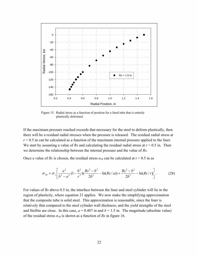
Substituting Po for σrp in this equation at r = 0.5 in, we get C = –29.64 ksi. Similarly, the stress in the steel can be found. The complete solution for this case is then shown in figure 15.
22
Radial Position, in
0.2 0.4 0.6 0.8 1.0 1.2 1.4 1.6
Rad
ial S
tres
s, k
si
-160
-140
-120
-100
-80
-60
-40
-20
0
Rs = 1.5 in
Figure 15. Radial stress as a function of position for a lined tube that is entirely plastically deformed.
If the maximum pressure reached exceeds that necessary for the steel to deform plastically, then there will be a residual radial stresses when the pressure is released. The residual radial stress at r = 0.5 in can be calculated as a function of the maximum internal pressure applied to the liner. We start by assuming a value of Rs and calculating the residual radial stress at r = 0.5 in. Then we determine the relationship between the internal pressure and the value of Rs.
Once a value of Rs is chosen, the residual stress σrR can be calculated at r = 0.5 in as
)/ln(
2))/ln(
2)(1(
2
22
2
22
2
2
22
2
rRsb
bRsaRs
b
bRs
r
b
ab
ayrR . (28)
For values of Rs above 0.5 in, the interface between the liner and steel cylinder will lie in the region of plasticity, where equation 21 applies. We now make the simplifying approximation that the composite tube is solid steel. This approximation is reasonable, since the liner is relatively thin compared to the steel cylinder wall thickness, and the yield strengths of the steel and Stellite are close. In this case, a = 0.407 in and b = 1.5 in. The magnitude (absolute value) of the residual stress σrR is shown as a function of Rs in figure 16.
23
Rs, in
0.4 0.6 0.8 1.0 1.2 1.4 1.6
Res
idua
l Rad
ial S
tres
s at
r =
0.5
in, k
si
0
5
10
15
20
25
30
35
r = 0.5 in
Figure 16. Residual stress at r = 0.5 in as a function Rs.
The residual radial stress should be closer to 0 at r = 0.5 in for Rs = 0.5 in than is shown in this plot. There is no mechanical bond between the liner and steel cylinder, so treating the tube as a monolithic piece of steel introduces this small error. It is also clear from these plots that the residual stress increases in magnitude as the plastic zone increases. Since it takes an increasing internal pressure to move the plastic zone outwards, the residual stress at the interface should increase in magnitude as the internal pressure increases. This is seen in figure 17, where the magnitude of the residual stress at r = 0.5 in is plotted as a function of the internal pressure. Note that there is no residual radial stress at r = 0.5 in for pressures below 74 ksi, consistent with previous results.
The maximum pressure achieved for the tests with the second Stellite-lined tube was 173 ksi. In reality, due to friction effects the internal pressure was lower than this value over most of the liner surface. Therefore, if the residual stress at the liner-steel cylinder interface is between 15 and 20 ksi, a bond strength of 3.2 ksi (achieved for sample RS 11) translates into a coefficient of friction between 0.16 and 0.21 ksi. Higher bond strengths appear achievable if the coefficient of friction can be raised by roughening the surface of either the Stellite or steel.
24
Internal Pressure, ksi
60 80 100 120 140 160 180 200
Res
idu
al r
adi
al S
tres
s a
t r =
0.5
in, k
si
0
5
10
15
20
25
30
35
r = 0.5 in
Figure 17. Magnitude of the residual radial stress at r = 0.5 in as a function of the internal pressure (all-steel tube).
5. Summary
A process by which a metal liner can be bonded to a steel gun tube has been described. The process consists of filling the liner with an elastomeric material, placing this arrangement in the gun tube and then loading the elastomeric material. The internal pressure expands the liner material, and if the pressure is high enough residual stresses keep the liner in place. Improvements in the fit of the seals used to contain the elastomeric material have resulted in gains in the maximum pressure achievable, leading to higher bond strengths. It was found that use of a high strength steel allowed higher maximum pressures to be attained. This is because the high strength steel prevented a great deal of expansion of the liner inner diameter, keeping the seals in close contact with the liner inner surface. For a soft steel, the inner diameter of the liner increased much more, and space between the liner and seal allowed the elastomeric material to escape, resulting in a lower maximum pressure.
Friction between the liner and elastomeric material prevented a uniform pressure along the liner wall. The effect was mitigated, to some extent, by the use of erucic acid as a high pressure lubricant. The residual pressure gradient results in a graded autofrettage taking place. That is, the residual stress will vary along the gun tube axis, resulting in different bond strengths.
25
6. References
1. Lowey, R. F. Gun Tube Liner Erosion and Wear Protection; TPL-FR-ER31; under contract DAAD19-99-C-0002; TPL, Inc.: Albuquerque, NM, May 2002.
2. de Rosset, W. S. Analysis of Explosive Bonding Parameters. Materials and Manufacturing Process 2006, 21, 6.
3. Carter, R. H.; de Rosset, W. S. Compressed Elastomer Method for Autofrettage and Lining Tubes, U.S. Army Research Laboratory, Patent Application 12/176,608, July 2008.
4. Carter, R. H. Compressed Elastomer Method for Internal Pressure Testing; ARL-TR-3921; U.S. Army Research Laboratory: Aberdeen Proving Ground, MD, September 2006.
5. de Rosset, W. S.; Montgomery, J. S. Machine Gun Liner Bond Strength; ARL-CR-595; U.S. Army Research Laboratory; Aberdeen Proving Ground, MD, August 2007.
6. de Rosset, W. S.; Snoha, D. J.; Minnicino, M. A. Strength of an Explosively-Formed Bond; ARL-TR-3889; U.S. Army Research Laboratory; Aberdeen Proving Ground, MD, September 2006.
7. Champagne, V. The Cold Spray Materials Deposition Process: Fundamentals and Applications; Woodhead Publishing Limited; Abington Hall: Abington Cambridge CB21 6AH, England, UK, 2007.
8. Mathaudhu, S. U.S. Army Research Laboratory, Aberdeen Proving Ground, MD. Private communication, August 2008.
9. Klier, E. U.S. Army Research Laboratory, Aberdeen Proving Ground, MD. Private communication, January 2008.
10. Online Materials Information Resource. http://www.matweb.com/ (accessed October 2008).
11. Goodheim, H.; Kendall, D. P. Autofrettage Design Manual of Gun Tubes; AMCMS No. 4930.16.6658, Benet R&E Laboratories: Watervliet Arsenal, Watervliet, NY, January 1970.
NO. OF COPIES ORGANIZATION
26
1 DEFENSE TECHNICAL (PDF INFORMATION CTR only) DTIC OCA 8725 JOHN J KINGMAN RD STE 0944 FORT BELVOIR VA 22060-6218 1 DIRECTOR US ARMY RESEARCH LAB IMNE ALC HRR 2800 POWDER MILL RD ADELPHI MD 20783-1197 1 DIRECTOR US ARMY RESEARCH LAB RDRL CIM L 2800 POWDER MILL RD ADELPHI MD 20783-1197 1 DIRECTOR US ARMY RESEARCH LAB RDRL CIM P 2800 POWDER MILL RD ADELPHI MD 20783-1197 1 DIRECTOR US ARMY RESEARCH LAB RDRL D 2800 POWDER MILL RD ADELPHI MD 20783-1197
ABERDEEN PROVING GROUND 1 DIR USARL RDRL CIM G (BLDG 4600)
NO. OF NO. OF COPIES ORGANIZATION COPIES ORGANIZATION
27
1 COMMANDER US ARMY TACOM ARDEC AMSRD AAR EM J HEDDERICH PICATINNY ARSENAL NJ 07806-5000 1 COMMANDER US ARMY TACOM ARDEC AMSRD AAR EMT B MACHAK BLDG B1 PICATINNY ARSENAL NJ 07806-5000 3 COMMANDER US ARMY TACOM ARDEC AMSRD AAR AEP E S GROESCHLER J LEE J VEGA BLDG 94 PICATINNY ARSENAL NJ 07806-5000 1 COMMANDER US ARMY TACOM ARDEC AMSRD AAR AEM J G FLEMING BLDG 65N PICATINNY ARSENAL NJ 07806-5000 2 COMMANDER US ARMY TACOM ARDEC AMSRD AAR EBM R CARR W SHARPE BLDG 1 PICATINNY ARSENAL NJ 07806-5000 3 COMMANDER US ARMY TACOM ARDEC SFAE AMO MAS LC R DARCY R JOINSON D RIGOGLIOSO BLDG 354 PICATINNY ARSENAL NJ 07806-5000 1 COMMANDER US ARMY TACOM ARDEC AMSRD AAR AEM L D VO BLDG 65 S PICATINNY ARSENAL NJ 07806-5000
1 COMMANDER US ARMY TACOM ARDEC AMSRD AAR AEM M LUCIANO BLDG 65 S PICATINNY ARSENAL NJ 07806-5000 2 COMMANDER US ARMY TACOM ARDEC AMSRD AAR AEM A VELLA J LUTZ BLDG 354 PICATINNY ARSENAL NJ 07806-5000 1 COMMANDER US ARMY TACOM ARDEC AMSRD AAR AEM T LOUZEIRO BLDG 65 PICATINNY ARSENAL NJ 07806-5000 2 COMMANDER US ARMY TACOM ARDEC AMSRD AAR AEE P D KAPOOR S KERWIEN BLDG 25 PICATINNY ARSENAL NJ 07806-5000 1 COMMANDER US ARMY TACOM ARDEC AMSRD AAR AEM L MANOLE BLDG 65N PICATINNY ARSENAL NJ 07806-5000 1 COMMANDER US ARMY TACOM ARDEC AMSRD AAR AIP M LOS BLDG 1 PICATINNY ARSENAL NJ 07806-5000 4 PM ARMS SFAE AMO MAS SMC R KOWALSKI F HANZL P RIGGS M BULTER BLDG 354 PICATINNY ARSENAL NJ 07806-5000
NO. OF NO. OF COPIES ORGANIZATION COPIES ORGANIZATION
28
2 BENET LABS RDAR WSB L A CRAYON E KATHE 1 BUFFINGTON ST WATERVLIET NY 12189 4050 3 BENET LABS RDAR WSB LC F CAMPO M MILLER M TODARO 1 BUFFINGTON ST WATERVLIET NY 12189 4050 4 BENET LABS RDAR WSB LB C MULLIGAN S SMITH E TROIANO G VIGILANTE 1 BUFFINGTON ST WATERVLIET NY 12189 4050 2 BENET LABS RDAR WSB LA A LITTLEFIELD M WITHERELL 1 BUFFINGTON ST WATERVLIET NY 12189 4050 1 US ARMY TARDEC AMSRD TAR R D TEMPLETON 6501 E 11 MILE RD WARREN MI 48397-5000 4 US ARMY RSRCH OFC J PRATER D STEPP D KISEROW L WALKER PO BOX 12211 RESEARCH TRIANGLE PARK NC 27709-2211 1 DIRECTOR US ARMY RESEARCH LAB RDRL CI 2800 POWDER MILL RD ADELPHI MD 20783-1197
ABERDEEN PROVING GROUND 38 DIR USARL RDRL LOA F M ADAMSON RDRL WM B FORCH J MCCAULEY P PLOSTINS J SMITH RDRL WML J NEWILL M ZOLTOSKI RDRL WML A T KOGLER RDRL WML B R LIEB R PESCE-RODRIGUEZ B RICE RDRL WML D P CONROY RDRL WML G A ABRAHAMIAN M BERMAN W DRYSDALE M MINNICINO RDRL WMM R DOWDING H MAUPIN RDRL WMM A R EMERSON RDRL WMM B T BOGETTI B CHEESEMAN RDRL WMM D E CHIN D GRANVILLE W ROY RDRL WMM E J LASALVIA J SWAB RDRL WMM F R CARTER W DE ROSSET L KECSKES J MONTGOMERY D SNOHA RDRL WMP P BAKER S SCHOENFELD

NO. OF COPIES ORGANIZATION
29
RDRL WMP B C HOPPEL RDRL WMP C T BJERKE RDRL WMP D T HAVEL J RUNYEON RDRL WMP E M BURKINS
30
INTENTIONALLY LEFT BLANK.