guidelines for waterway signs and marking
TRANSCRIPT
GE.13-
ECE/TRANS/SC.3/169/Rev.1
ECONOMIC COMMISSION FOR EUROPE
INLAND TRANSPORT COMMITTEE
Working Party on Inland Water Transport
Guidelines for Waterway Signs
and Marking Resolution No. 59
Revision 1
UNITED NATIONS New York and Geneva, 2013
ECE/TRANS/SC.3/169/Rev.1
2
Amendments to Resolution No. 59 on Guidelines for Waterway Signs and Marking
Resolution No. 75 (adopted by the Working Party on Inland Water Transport on 12 October 2012)
The Working Party on Inland Water Transport,
Considering its Resolution No. 24 “CEVNI: European Code for Inland Waterways”, as amended by resolutions Nos. 26, 27, 37, 39, 43–47, 54, 62 and 66 (TRANS/SC.3/115/ Rev.4),
Considering also its Resolution No. 22 “SIGNI: Signs and Signals on Inland Waterways”, as amended by resolutions Nos. 29, 51 and 67 (TRANS/SC.3/108/Rev.2),
Considering further its Resolution No. 59 “Guidelines for Waterway Signs and Marking” of 20 October 2005 (TRANS/SC.3/169),
Bearing in mind the report of the Working Party on the Standardization of Technical and Safety Requirements in Inland Navigation on the work of its fortieth session (ECE/TRANS/SC.3/WP.3/80, paragraphs 39–41),
Desirous, in the interest of safety of navigation, of establishing homogeneous rules for waterway signs and marking prescribed by CEVNI and SIGNI as well as for their visibility and installation,
1. Decides to replace the text of the annex of Resolution No. 59 with the text contained in the annex of this resolution;
2. Requests Governments to inform the Executive Secretary of the Economic Commission for Europe whether they accept this resolution;
3. Requests the Executive Secretary of the Economic Commission for Europe to place the question of the application of this resolution periodically on the agenda of the Working Party on Inland Water Transport.

ECE/TRANS/SC.3/169/Rev.1
3
Annex
Guidelines for Waterway Signs and Marking
1. General
1.1 In terms of the objective pursued, the marking comprises two categories of signs:
• signs used to regulate navigation on the waterway, set out in annex 7 of the European code for inland waterways (CEVNI), and
• signs and signals on the water and bank marks marking the sides of the fairway and navigational hazards, set out in annex 8 to CEVNI.
In order to increase the safety of navigation, the competent authorities referred to in article 1.9 shall place kilometre markings along the inland waterway wherever waterway dimensions allow, as well as mark off each hectometre wherever possible.
1.2 The signs set out in annex 7 to CEVNI are prohibitory, mandatory, restrictive, recommendatory or informative signs and auxiliary signs.
1.3 In accordance with article 5.01 of CEVNI, boatmen shall obey the requirements and take account of the recommendations or indications brought to their attention by these signs.
1.4 The signs and signals on the water and bank marks of annex 8 to CEVNI are used to indicate the limits, the direction and the depth of the waterway and, in addition, are used to mark obstacles and permanent structures in the fairway or in its vicinity.
1.5 The number of bank marks and signs and signals on the water and the plan for their on-site location shall meet the requirements of navigational safety.
1.6 The choice of the marks and the establishment of their number depends on the local characteristics of the waterway and the function of each mark. Their installation shall be effected in such a way as to ensure visibility from one mark to the next.
1.7 The luminous range of lights is established by the competent authorities of the respective countries in terms of local navigational conditions. In calculating the luminous range, the atmospheric transmission coefficient 0.6 should be used over a distance of 1 nautical mile.
1.8 In principle, the colours of lights should be in keeping with the recommendations of the International Commission on Illumination (“Colours of Light Signals”, CIE Publication No. 2.2–1975 (TC–1.6)).
1.9 The marks shall be installed by the competent authorities which:
(a) regularly observe the state of the bed of the river and the changes taking place in it and, on the basis of the results of these observations, correct the positioning of the signs and marks and, where necessary, add to them so that they indicate the fairway dimensions;
(b) regularly measure the depth and the width of the marked fairway and provide boatmasters with the necessary information concerning minimum fairway depths and widths and the river level regime;
ECE/TRANS/SC.3/169/Rev.1
4
(c) establish the plan for the installation of signs and marks in their respective sectors and establish the type and number of signs and signals on the water and bank marks to be used, in terms of the requirements of navigational safety and local conditions;
(d) ensure the uninterrupted operation of all signs and signals on the water and bank marks;
(e) inform boatmasters in good time of the date of the installation and removal of signs and signals, of all alterations to their number, type, positioning and lighting, and the rules they establish permitting the passage of vessels in restricted sections where meeting and passing are prohibited.
2. Requirements to be met by signs and marks and the plan for their installation
2.1 Marking shall be in operation continuously (by day and night) all along the navigable section of the river, as from when the waterway is free from ice until the ice appears; it shall be corrected as changes occur in the level and in the fairway.
In accordance with the state of the fairway, the marking shall be positioned in such a way that the vessels navigating downstream can use the part of the river with the high current speed and the vessels navigating upstream can use the part of the river with the low current speed.
2.2 During periods of high water and icing, the regular marking removed to preserve it from possible damage shall be replaced, as far as possible, by marker posts and spars the topmarks and colours of which shall correspond to those adopted for the respective side of the fairway.
2.3 The bank marks and the additional signs and signals on the water shall, if possible, operate until navigation becomes completely impossible because of ice.
2.4 Signs and signals on the water shall be installed so as to ensure the safety of vessels on the fairway.
2.5 Buoys shall be unsinkable and shall remain unsinkable in all storms, and their main body shall therefore be watertight; they shall not only float but also be stable, i.e. conserve a vertical position as far as possible and not be tipped excessively by waves and wind.
2.6 The basic condition which the plan for the installation of the signs and marks shall meet is to ensure the safety of the vessels and the continuity of traffic, by day and by night, throughout the sailing season and to give boatmasters clear and unambiguous indications concerning the direction and the limits of the fairway.
2.7 The plan for the installation of the signs and marks shall be prepared in such a way as to permit a rational combination of bank marks and signs and signals on the water. When the plan is drawn up, it should be based on the conditions of navigation and specific hydrographical and hydrometeorological conditions, the need to ensure the established dimensions of the fairway and create the necessary conditions for the safety and continuity of navigation of all river vessels and, where necessary, of seagoing vessels.
2.8 Bank marks serve to guide boatmasters and to indicate the direction of the fairway. Signs and signals on the water supplement bank marks in sectors where, in order to ensure the safety of navigation, it is essential to indicate not only the direction of the fairway but also its limits, and to mark places where there are obstacles.

ECE/TRANS/SC.3/169/Rev.1
5
2.9 In preparing the plan for the installation of signs and marking, the following requirements should be taken into account:
(a) only the signs set out in annexes 7 and 8 to CEVNI are to be used to mark the fairway and regulate navigation; in exceptional cases, special additional bank marks may also be used, provided, however, that the marks are not in contradiction with those contained in CEVNI;
(b) the dimensions of the marked fairway shall correspond to the dimensions published by the competent authorities;
(c) the choice of where the signs are to be placed shall be based on the most recent measurements, acquired experience and available data on the state of the fairway, critical points, water levels, etc.;
(d) signs and marker lights shall be visible, whatever the level of the water, at all points of the fairway and as long as may be necessary for the guidance of boatmasters;
(e) the marking plan shall contain information on the type of placed signs, bank/side whereon placed, river kilometre of the set-up and recapitulation of all signs and signals on the water and bank marks used for marking.
2.10 If there is a subsequent drop in the level of the water, reconnaissance soundings shall be taken on some sections of the river in order to check whether the positioning of the signs is adequate and to establish whether the marking needs to be supplemented by new signs.
2.11 The frequency of these soundings shall be determined by changes in water level. The more rapid the drop in levels, the more frequent the soundings need to be.
3. Visibility of signs and lights
3.1 Whatever the position of the vessel in relation to the sign or the marker light, the characteristics of the sign or light shall remain unchanged. For daytime signs, these characteristics are: the form (topmark) and the colour; for signs and signals at night: the type and colour of the lights.
3.2 The forms and the colours of the topmarks and the types and colours of the lights are set out in detail in annexes 7 and 8 to CEVNI.
3.3 Sketches of the signs and marks with the minimal dimensions are given in the Appendix 1 to these guidelines. The numbering of the sketches corresponds to the numbering of the signs and marks given in annexes 7 and 8 to CEVNI.
Conditions of visibility and dimensions of signs
3.4 The basic requirement to be met by signs and marking is the guarantee of good visibility of all signs and signals by day or night.
3.5 There are three degrees of visibility of signs and signals:
(a) First: when, because of the distance, the sign is no more than a blotch on the background and neither shape nor colour can be distinguished (dotted outline);
(b) Second: when the sign is visible and its shape and outline can be seen, but the colour remains unclear;
(c) Third: When the shape and colour of the sign can be seen distinctly.
ECE/TRANS/SC.3/169/Rev.1
6
Signs that must be seen by a boatmaster at some imperative distance (“no entry”, “keep a particular sharp lookout”, etc.) must have a visibility (due to their proper dimensions) of second or third degree. The type and dimensions of signs should be selected accordingly.
3.6 The degree of visibility of a sign, as of any object, depends primarily on the size of the angle of sight, the colour contrast, the contrast in luminance and weather conditions.
3.7 In order to ensure the visibility of first degree, the sign shall be visible under 1' angle by day and under 10' angle by night. Detailed form and colour of the sign (visibility of second and third degree) are identified under even larger angles.
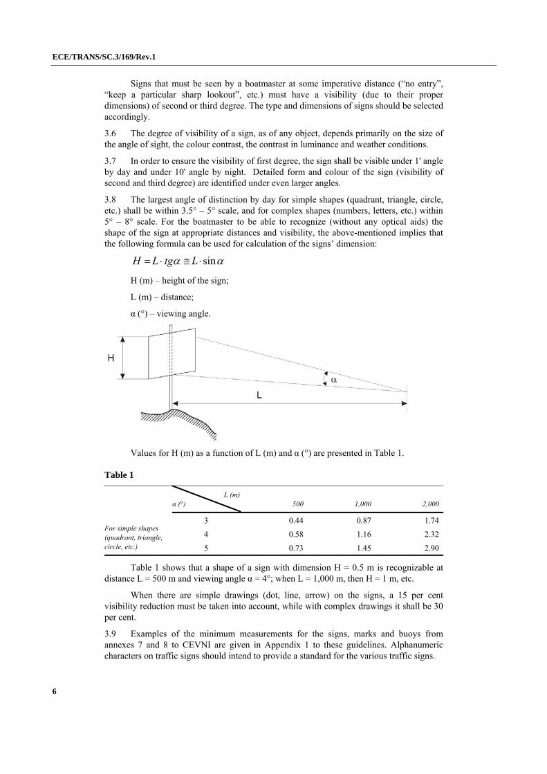
3.8 The largest angle of distinction by day for simple shapes (quadrant, triangle, circle, etc.) shall be within 3.5° – 5° scale, and for complex shapes (numbers, letters, etc.) within 5° – 8° scale. For the boatmaster to be able to recognize (without any optical aids) the shape of the sign at appropriate distances and visibility, the above-mentioned implies that the following formula can be used for calculation of the signs’ dimension:
sin LtgLH
H (m) – height of the sign;
L (m) – distance;
α (°) – viewing angle.
Values for H (m) as a function of L (m) and α (°) are presented in Table 1.
Table 1
For simple shapes (quadrant, triangle, circle, etc.)
L (m)α (°) 500 1,000 2,000
3 0.44 0.87 1.74
4 0.58 1.16 2.32
5 0.73 1.45 2.90
Table 1 shows that a shape of a sign with dimension H = 0.5 m is recognizable at distance L = 500 m and viewing angle α = 4°; when L = 1,000 m, then H = 1 m, etc.
When there are simple drawings (dot, line, arrow) on the signs, a 15 per cent visibility reduction must be taken into account, while with complex drawings it shall be 30 per cent.
3.9 Examples of the minimum measurements for the signs, marks and buoys from annexes 7 and 8 to CEVNI are given in Appendix 1 to these guidelines. Alphanumeric characters on traffic signs should intend to provide a standard for the various traffic signs.
ECE/TRANS/SC.3/169/Rev.1
7
The letters, figures and analogous symbols should be of a height not less than one five-hundredth of the maximum distance from which they must be read, and the thickness of the stroke should be not less than one-seventh of that height.1
For bank marks and signs, the minimal height from the lower rim of the board down to the ground shall be 3 m. In places where it is necessary due to the configuration of the terrain (relief), a height of 2 m is allowed. At highest navigation water levels, the height of the water level up to the lower rim of the board should not be less than 1.5 m.
3.10 As regards the signs and signals of annex 8 to CEVNI, unlighted buoys and unlighted bank mark boards shall be covered with reflective material. Light buoys and lighted bank mark boards may also be so covered. The colours of these materials shall correspond to those established for the buoy lights or the boards. In all cases, the topmarks of light buoys shall be covered with reflective paint.
3.11 In order to ensure that bank marks are clearly visible, their dimensions shall be determined in terms of their purpose, the distance between the fairway and the banks, the nature of the region and the characteristics or other specific conditions of the sector in question.
3.12 The good visibility of a sign or signal depends on the contrast between the luminance of the sign or signal and the background. This shall be taken into consideration in choosing a site for signs and signals. For example, of two boards, one red and the other white, positioned one beside the other against a light background, the red board will be more visible and visible at a greater distance than the white board while, in contrast, the white board will be easier to see than the red board against a dark background.
3.13 The visibility of signs and signals of annex 7 to CEVNI regulating navigation on the waterway shall be ensured at night by lighting them with fixed directional white lights, operating uninterruptedly and so positioned that the light does not incommode the boatmasters.2
If electric lighting cannot be used, the sign boards shall be covered with reflective material of a corresponding colour on which the symbol shall be clearly visible to vessels.
3.14 When boards are lighted, it should be ensured that the shade of their colour is unchanged. The luminance of the sign or signal perceived, like that of any object, depends not only on the lighting but also on the capacity of the surface of the sign to reflect the light waves falling on it. This shall be taken into consideration when the signs are painted; this shall be done in such a way that the surface of the sign is smooth and reflects the light properly and is not dull and covered with an uneven coat of paint.
Conditions for the visibility of lights
3.15 In certain cases lighting may be provided at night (e.g. lighting of the lower part of a bridge, of the piers of a bridge, of the approaches to a lock, of a section of a canal, etc.). Such lighting may be used to supplement the markings. Lighting shall be so designed as to avoid dazzling.3
3.16 It is recommended that the luminous intensity of a light should be determined according to Part II of appendix 7 to Resolution No. 61 of the UNECE Working Party on
1 This provision is taken from Resolution No. 22 “SIGNI − Signs and signals on inland waterways” (ECE/TRANS/SC.3/108/Rev.2), hereafter − SIGNI.
2 The competent authorities may waive these requirements. 3 This text is from SIGNI.

ECE/TRANS/SC.3/169/Rev.1
8
Inland Water Transport “Recommendations on Harmonized Europe-Wide Technical Requirements for Inland Navigation Vessels”.4
3.17 Since the intensity of light should be higher for the colour lights produced by application of filters, a stronger source of light is needed. Table 2 shows the intensity of sources of light calculated for atmospheric conditions of light haze:
Table 2
Visibility (m)
Intensity of light (cd) Intensity of source of light (cd)
White light White light Red light Green light
500 0.06 0.06 0.40 0.60
1 000 0.25 0.25 1.70 2.50
2 000 1.40 1.40 9.30 14.00
3 000 4.20 4.20 28.00 42.00
4 000 9.80 9.80 65.00 99.00
5 000 20.00 20.00 133.00 200.00
3.18 The duration of the flash of a signal light shall not be less than 0.5 seconds. Shorter flashes, even if they are frequent, are tiring on the boatmaster’s eyes and hinder orientation. Long and infrequent flashes on the other hand also hinder orientation, since while waiting for the next flash the boatmaster cannot be sure that he is still proceeding in the desired direction.
3.19 Details of the characteristics of signal lights used can be found in annex 8 to CEVNI.
Obligation not to hinder road and rail traffic
3.20 Signs and marking shall be installed in such a way that their lights do not hinder the movements of other modes of transport if the road runs close to the river.
3.21 In a sector in which a road or a railway runs close to a river, the installation of all the above-mentioned signs and signals shall be carried out in consultation with the respective competent authorities.
4. Installation of signs and marking in characteristic sections of the river
4.1 General
4.1.1 Signs have two possible orientations, namely:
(a) parallel to the axis of the fairway;
(b) perpendicular to the axis of the fairway.
4.1.2 Signs of type (a) are predominantly prohibitory or indicative signs, and are placed on the side of the fairway to which the prohibition or the indication applies.
4 The alternative proposal is to refer to Recommendation on the Determination of the Luminous Intensity of Marine Aid-to-navigation Lights, December 1977, published in the IALA Bulletin No. 75–1978–3, as done in SIGNI.
ECE/TRANS/SC.3/169/Rev.1
9
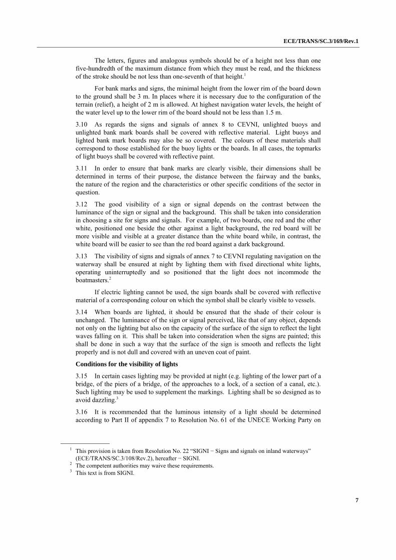
Bank marks which are used in relation to navigation in both directions (upstream and downstream) shall be oriented as under (a). In some cases (better visibility) the angle between the mark and the axis of the fairway can be 10° or less. (Figure 1, sign a).
4.1.3 Most signs are positioned as described under (b), and generally do not apply to one side of the fairway only. These signs are erected at right angles to the axis of the fairway so that they are visible to a user when under way.
Bank marks which are used in relation to navigation in one direction (upstream or downstream) shall be oriented as under (b). In some cases (better visibility) the angle between the mark and the axis of the fairway cannot be less than 60° (Figure 1, sign c).
4.1.4 The use of a particular sign or signal on the water or bank mark and how it is installed depends on the one hand on the local features of the river (speed of current, variation in levels, meanders, width of the bed, existence of sills, branches, islands, etc.), and on the other hand on the density of traffic in a given sector and the form and size of convoys.
4.1.5 The position of each sign or signal on the water indicating the side of the fairway shall be determined on the basis of the marking installation plan based on the results of measurements. Depths within the limits of the width of the marked fairway shall under no circumstances be less than the minimum depth reported for the sector in question.
4.1.6 When signs and signals are installed on the water, it is essential to take the direction of the current into account. If the current flows in the direction of an obstacle, the sign or signal shall always be placed a long way from the navigational hazard (obstacle); if, on the other hand, it flows in the opposite direction, the sign or signal shall be placed nearer.
4.1.7 Obstacles on the sides of the fairway are always marked with signs or signals on the water. When the obstacle is indicated by a single sign, it shall be placed on the upstream extremity of the obstacle, on the fairway side (Figure 1, sign b).
Figure 1
4.1.8 As a rule, lighted buoys or unlighted buoys shall be used to mark the upstream and downstream extremities of sills, banks which narrow the fairway, alluvial channels, banks protruding into the fairway, piles of stones, reefs, water supply engineering structures, and underwater hazards or obstacles (sunken vessels, anchors, etc.).
4.1.9 Marker posts and spars shall be used as additional signs supplementing buoys in order to give a clearer indication of the limits of the fairway over difficult sills and in order to mark underwater obstacles. In some cases and in some sectors, buoys may be replaced by marker posts or spars.
4.1.10 In order to avoid damage to buoys during the period when ice is carried down, they shall be replaced by spars or marker posts.
4.1.11 On sectors of the river where there is day and night navigation, forks, junctions and the centerline of the fairway, along with obstacles to navigation lying within
ECE/TRANS/SC.3/169/Rev.1
10
the fairway, shall be marked by light buoys or bank lights. Signs and signals on the water shall be installed at such a depth and at such a distance from the obstacle that the safety and ease of movement of vessels shall be guaranteed at night and in poor visibility.
4.1.12 On sectors where the fairway is narrow, preference shall be given to marks on the banks.
4.1.13 Each sign or signal on the bank shall be established following reconnaissance of the area and selection of the most appropriate site. The need to ensure the visibility of the sign whatever the level of the water should be taken into consideration.
4.1.14 Where it is necessary to ensure good visibility of the symbol on the sign over a long distance, both for vessels proceeding upstream and vessels proceeding downstream, two boards may be installed on the sign pole at an angle to each other, one pointing upstream and the other downstream.
4.1.15 In selecting the site of a sign or signal on the bank, account shall be taken of the need to ensure easy maintenance and to protect it against ice and flooding.
4.1.16 Before a bank sign or signal is installed, the depth in the area in front of it and in the direction it indicates shall always be measured.
4.1.17 As a general rule, the objective is that only the network of signs and signals on the bank shall provide an uninterrupted indication of the position of the fairway as a whole, while the signs and signals on the water shall help boatmasters to determine the limits of the fairway.
4.2 Marking of alluvial channels
4.2.1 Installation of cross-channel fairway signs and bank lights
4.2.1.1 Cross-channel fairway signs and bank lights may be used in alluvial channels in order to indicate that the fairway crosses over from one bank to the other (signs featured in 4.C, 4.D, 5.C, 5.D in annex 8 to CEVNI).
4.2.1.2 Alluvial channels are marked by bank lights and cross-channel fairway signs when the fairway is sufficiently broad, its safety is ensured, and when the direction only requires to be indicated approximately.
4.2.1.3 Bank lights and cross-channel fairway signs shall be selected in such a way as to differentiate cross-channel fairways in terms of their length, in other words in terms of the distance between two neighbouring signs. The length of the cross-over is relative, since it depends on the width of the fairway.
4.2.1.4 The cross-channel fairway signs and bank lights have best results on distances up to 3 km. On such sections, cross-channel fairway signs and bank lights (without signs on the water) can be placed under conditions where the available width for navigation is more than two times wider than the minimum prescribed width of the fairway for a particular sector. If the available width for navigation is less than the minimum prescribed width of the fairway for a particular sector, cross-channel fairway signs and bank lights (without signs on the water) cannot be placed at distance greater than 1–1.5 km.
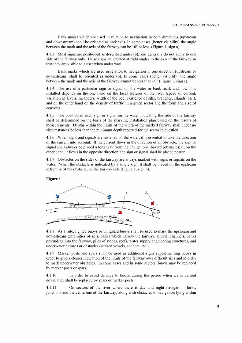
4.2.1.5 If the distance between two neighbouring cross-channel fairway signs is larger than the calculated visibility, and when the navigation line passes nearby the bank, the bank lighted sign, which additionally marks the position of the navigation line, is placed between those two neighbouring cross-channel fairway signs (Figure 2, sign a). The bank lighted sign is also placed when the fairway passes near the bank (Figure 2, sign b).
ECE/TRANS/SC.3/169/Rev.1
11
Figure 2
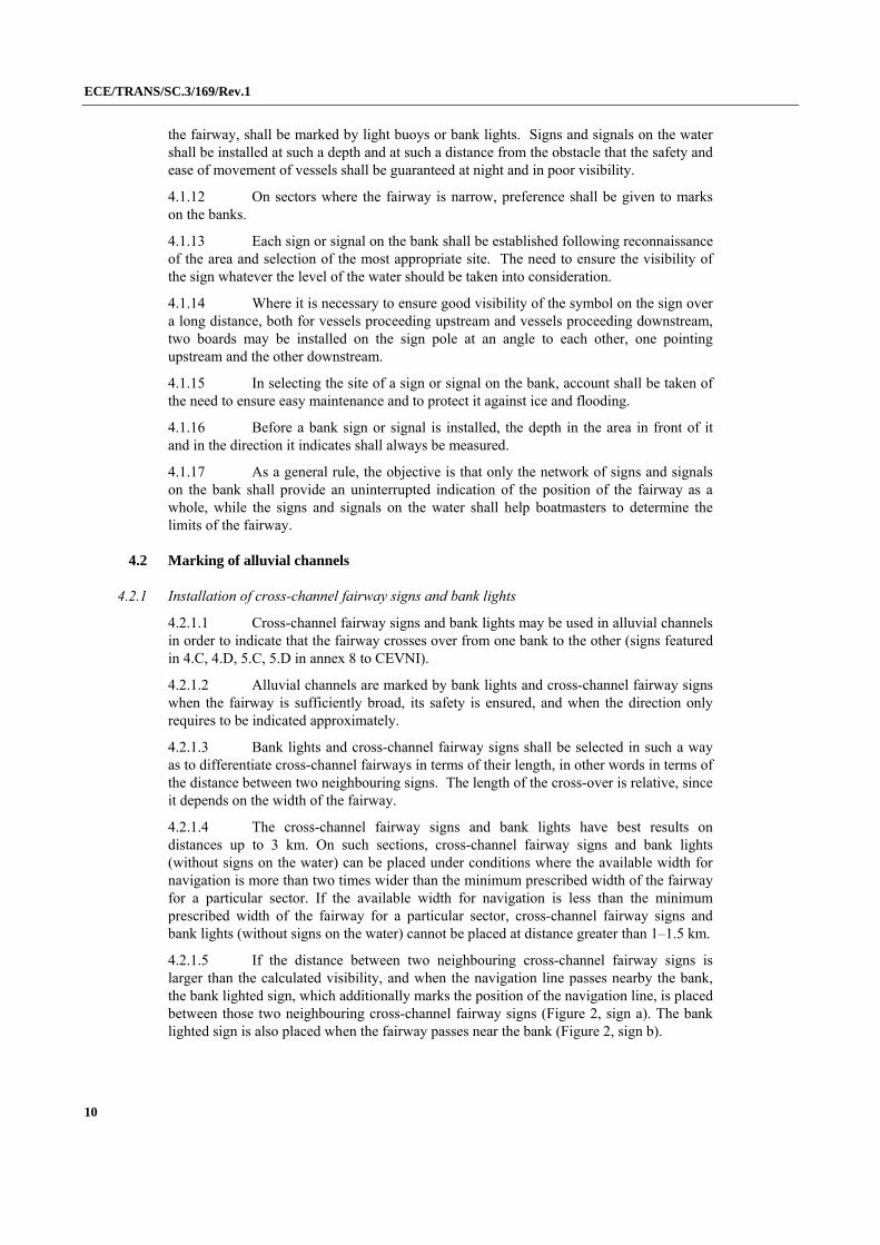
4.2.1.6 In case the direction of the current makes an angle with the fairway, when strong side winds or a similar situation occurs, the fairway can be marked by additional navigation marks according to the local conditions (Figure 3).
Figure 3
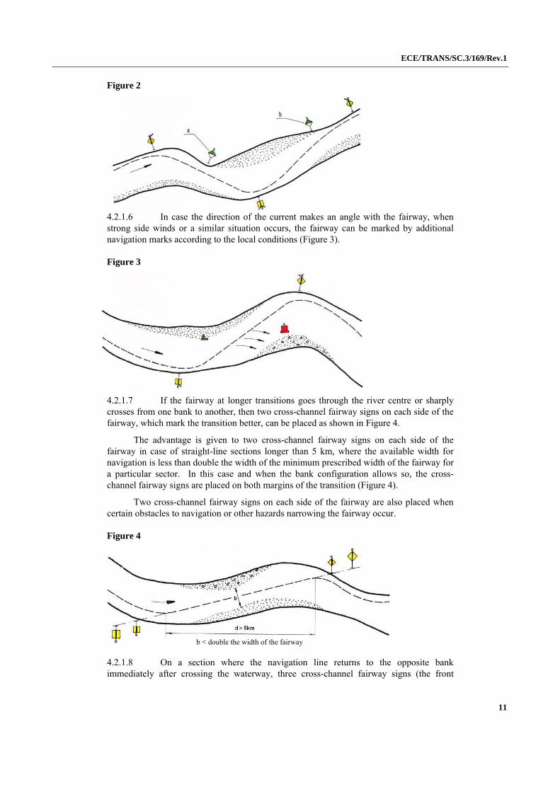
4.2.1.7 If the fairway at longer transitions goes through the river centre or sharply crosses from one bank to another, then two cross-channel fairway signs on each side of the fairway, which mark the transition better, can be placed as shown in Figure 4.
The advantage is given to two cross-channel fairway signs on each side of the fairway in case of straight-line sections longer than 5 km, where the available width for navigation is less than double the width of the minimum prescribed width of the fairway for a particular sector. In this case and when the bank configuration allows so, the cross-channel fairway signs are placed on both margins of the transition (Figure 4).
Two cross-channel fairway signs on each side of the fairway are also placed when certain obstacles to navigation or other hazards narrowing the fairway occur.
Figure 4
4.2.1.8 On a section where the navigation line returns to the opposite bank immediately after crossing the waterway, three cross-channel fairway signs (the front
b < double the width of the fairway

ECE/TRANS/SC.3/169/Rev.1
12
should have two boards) are mandatorily placed (Figure 5). In that case, lights of the back cross-channel fairway signs should be strictly directed to the fairway axis: one to upstream and one to downstream.
Figure 5
4.2.1.9 Interrelationships of the front and back signs at hidden routes shorter than 4 km are presented in Table 3.
Table 3
L(m) d(m) ho(m) a(m) 2a(m)
200 17 8.50 2.6 5.0
300 25 8.70 4.0 8.0
400 33 8.85 5.2 10.5
500 42 9.00 6.5 13.0
600 50 9.10 8.0 16.0
700 58 9.20 9.0 18.0
800 67 9.35 10.0 20.0
900 75 9.50 12.0 24.0
1 000 83 9.60 13.0 26.0
1 500 125 10.25 19.0 38.0
2 000 166 10.90 26.0 52.0
2 500 207 11.50 33.0 66.0
3 000 250 12.15 39.0 78.0
3 500 290 12.75 46.0 92.0
4 000 330 13.40 52.0 104.0
> 4 000 760 14.20 25.0 50.0
L (m) – maximal distance when cross-channel fairway signs can be used;
d (m) – distance between front and back signs (is approximately L
12
1
);
ho (m) – height between lights of front and back sign;
a (m) – distance necessary for a vessel to adjust its course if the vessel does not go along the cross-channel fairway;
ECE/TRANS/SC.3/169/Rev.1
13
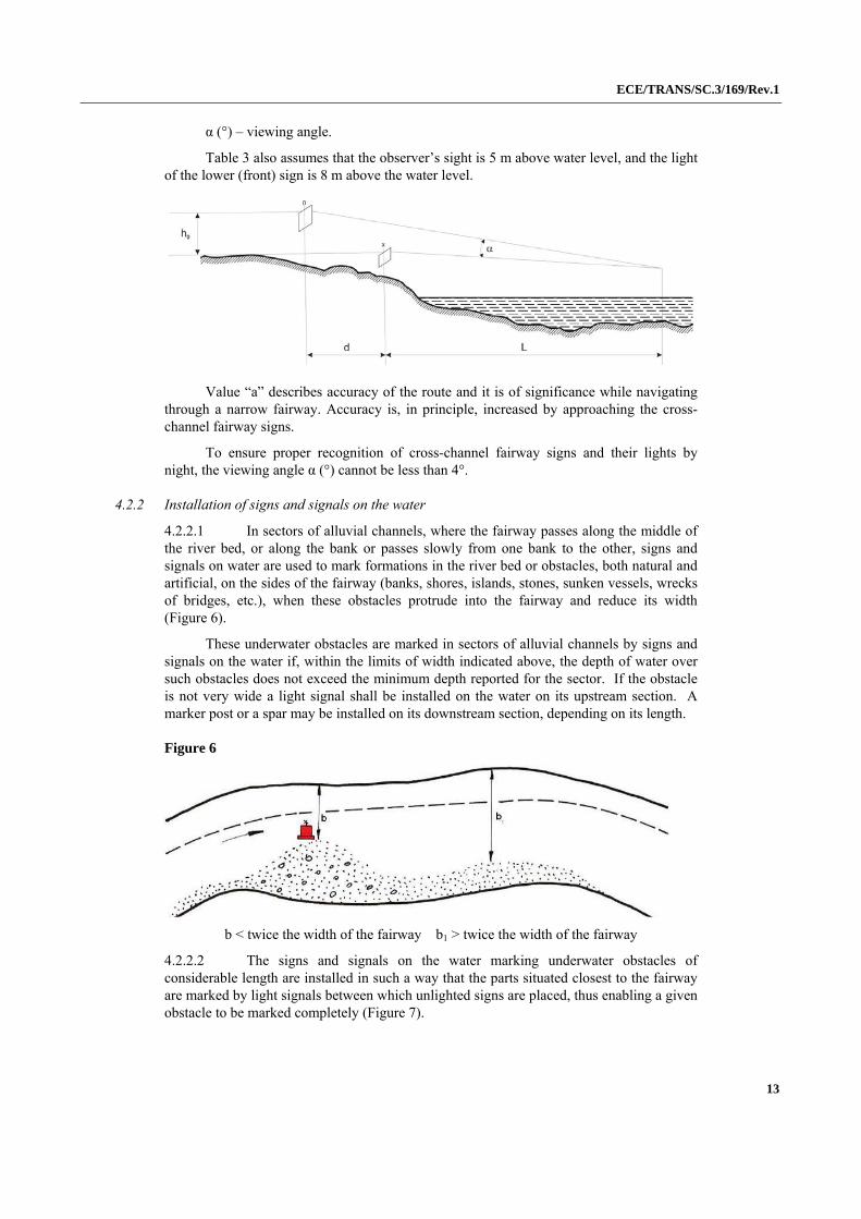
α (°) – viewing angle.
Table 3 also assumes that the observer’s sight is 5 m above water level, and the light of the lower (front) sign is 8 m above the water level.
Value “a” describes accuracy of the route and it is of significance while navigating through a narrow fairway. Accuracy is, in principle, increased by approaching the cross-channel fairway signs.
To ensure proper recognition of cross-channel fairway signs and their lights by night, the viewing angle α (°) cannot be less than 4°.
4.2.2 Installation of signs and signals on the water
4.2.2.1 In sectors of alluvial channels, where the fairway passes along the middle of the river bed, or along the bank or passes slowly from one bank to the other, signs and signals on water are used to mark formations in the river bed or obstacles, both natural and artificial, on the sides of the fairway (banks, shores, islands, stones, sunken vessels, wrecks of bridges, etc.), when these obstacles protrude into the fairway and reduce its width (Figure 6).
These underwater obstacles are marked in sectors of alluvial channels by signs and signals on the water if, within the limits of width indicated above, the depth of water over such obstacles does not exceed the minimum depth reported for the sector. If the obstacle is not very wide a light signal shall be installed on the water on its upstream section. A marker post or a spar may be installed on its downstream section, depending on its length.
Figure 6
b < twice the width of the fairway b1 > twice the width of the fairway
4.2.2.2 The signs and signals on the water marking underwater obstacles of considerable length are installed in such a way that the parts situated closest to the fairway are marked by light signals between which unlighted signs are placed, thus enabling a given obstacle to be marked completely (Figure 7).

ECE/TRANS/SC.3/169/Rev.1
14
Figure 7
4.2.2.3 In the parts of the river bed where the shore opposite that followed by the fairway is bordered by an inshore bank which favours upstream navigation in calm water, the bank is marked by signs and signals on the water independently of the width of the bed.
4.2.2.4 In sectors of alluvial channels, the bank marking system in periods of high water generally remains the same as in periods of lowest water level, except in sectors where, when water levels are high, it is advisable to find another fairway with better navigational features. In this case, the selected fairway shall be marked appropriately.
4.3 Shallow water marking
4.3.1 In shallow water, as in other sections, sets of marks ensuring a continuous marking of the fairway shall be installed.
In shallow water the fairway can be marked by cross-channel fairway signs, bank marks and signs and signals on the water.
4.3.2 Alternately located shallow waters may also be marked by cross-channel fairway signs, with sufficient available width for navigation in which vessels are passing in a straight line (Figure 8).
Figure 8
4.3.3 A fairway passing over shallow water is usually marked by signs and signals on the water (Figures 8 and 9).
ECE/TRANS/SC.3/169/Rev.1
15
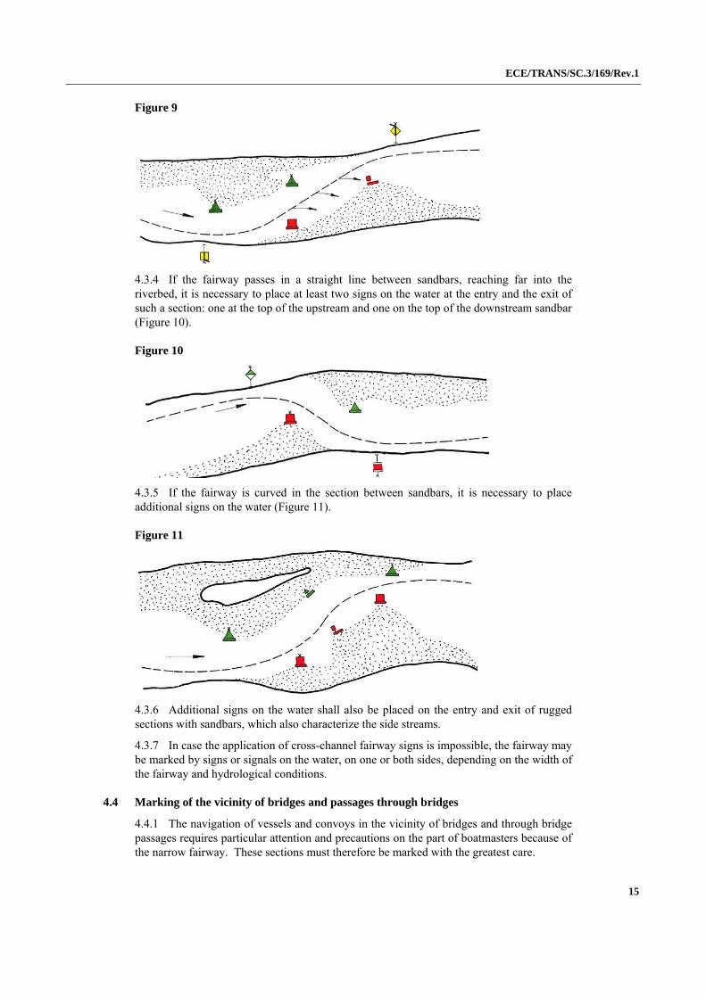
Figure 9
4.3.4 If the fairway passes in a straight line between sandbars, reaching far into the riverbed, it is necessary to place at least two signs on the water at the entry and the exit of such a section: one at the top of the upstream and one on the top of the downstream sandbar (Figure 10).
Figure 10
4.3.5 If the fairway is curved in the section between sandbars, it is necessary to place additional signs on the water (Figure 11).
Figure 11
4.3.6 Additional signs on the water shall also be placed on the entry and exit of rugged sections with sandbars, which also characterize the side streams.
4.3.7 In case the application of cross-channel fairway signs is impossible, the fairway may be marked by signs or signals on the water, on one or both sides, depending on the width of the fairway and hydrological conditions.
4.4 Marking of the vicinity of bridges and passages through bridges
4.4.1 The navigation of vessels and convoys in the vicinity of bridges and through bridge passages requires particular attention and precautions on the part of boatmasters because of the narrow fairway. These sections must therefore be marked with the greatest care.
ECE/TRANS/SC.3/169/Rev.1
16
4.4.2 The basic condition to be met to ensure safe passage through bridges is the marking of the direction of the fairway and also, where necessary, its sides. Signs and signals on the water and on the banks may be used in addition to boards and lights for marking the navigable passage through bridges.
4.4. 3 The choice and positioning of the signs depends in each case on local conditions in the bridge section.
4.4.4 The installation of marking signs in the vicinity of bridges and the buoying of navigable passages shall comply with the following conditions:
(a) in order to indicate permission to use the navigable passage of a bridge, only signs A.10, D.1 or D.2 in annex 7 to CEVNI shall be used;
(b) the installation of marking signs shall be based on depth and current direction measurements, both in the immediate vicinity of the bridge and in the approach sections;
(c) the positioning of the signs installed in the vicinity of a bridge shall be modified in due course, as conditions of navigation change;
(d) if, when approaching the bridge or the navigable passage, the direction of the current forms an angle with the bridge, giving rise to eddies around the pillars of the bridge, the signs on the water shall be so installed as to indicate the direction of the eddies.
4.4.5 Signs and signals may be installed on the water at the approach to the navigable passage to give an exact indication of the position of the fairway.
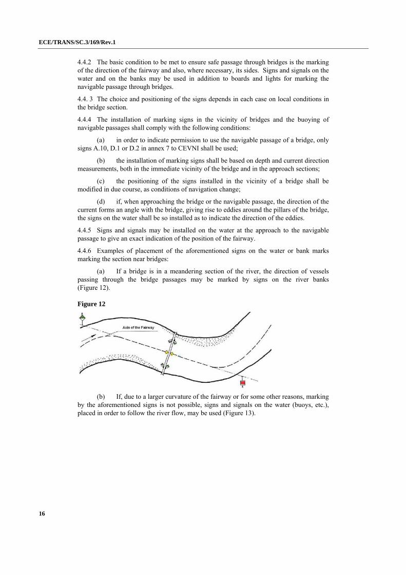
4.4.6 Examples of placement of the aforementioned signs on the water or bank marks marking the section near bridges:
(a) If a bridge is in a meandering section of the river, the direction of vessels passing through the bridge passages may be marked by signs on the river banks (Figure 12).
Figure 12
(b) If, due to a larger curvature of the fairway or for some other reasons, marking by the aforementioned signs is not possible, signs and signals on the water (buoys, etc.), placed in order to follow the river flow, may be used (Figure 13).
ECE/TRANS/SC.3/169/Rev.1
17
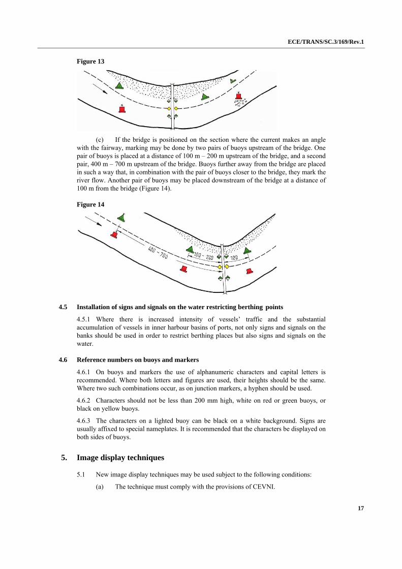
Figure 13
(c) If the bridge is positioned on the section where the current makes an angle with the fairway, marking may be done by two pairs of buoys upstream of the bridge. One pair of buoys is placed at a distance of 100 m – 200 m upstream of the bridge, and a second pair, 400 m – 700 m upstream of the bridge. Buoys further away from the bridge are placed in such a way that, in combination with the pair of buoys closer to the bridge, they mark the river flow. Another pair of buoys may be placed downstream of the bridge at a distance of 100 m from the bridge (Figure 14).
Figure 14
4.5 Installation of signs and signals on the water restricting berthing points
4.5.1 Where there is increased intensity of vessels’ traffic and the substantial accumulation of vessels in inner harbour basins of ports, not only signs and signals on the banks should be used in order to restrict berthing places but also signs and signals on the water.
4.6 Reference numbers on buoys and markers
4.6.1 On buoys and markers the use of alphanumeric characters and capital letters is recommended. Where both letters and figures are used, their heights should be the same. Where two such combinations occur, as on junction markers, a hyphen should be used.
4.6.2 Characters should not be less than 200 mm high, white on red or green buoys, or black on yellow buoys.
4.6.3 The characters on a lighted buoy can be black on a white background. Signs are usually affixed to special nameplates. It is recommended that the characters be displayed on both sides of buoys.
5. Image display techniques
5.1 New image display techniques may be used subject to the following conditions:
(a) The technique must comply with the provisions of CEVNI.
ECE/TRANS/SC.3/169/Rev.1
18
(b) Deviation from the original colours is possible for some signs when implementing a new technique. This is dealt with in the descriptions of the relevant signs.
(c) Because new display techniques sometimes make use of images composed of many pixels, special consideration needs to be given to image design.
(d) A general characteristic of the new display techniques is that the text and images can be controlled remotely; variable images are possible within a single display. Phantom effects, i.e. reflective effects and illusions caused by the incidence of sunlight, can be controlled.
Examples of the new image display techniques are given in Appendix 2.
6. Installation of radar reflectors on marking signs and signals
6.1 It is important to equip signs on the water and on the banks with radar reflectors to ensure their visibility.
6.2 When marking signs equipped with radar reflectors are installed, account must be taken of the furthest distance between the vessel and the sign in terms of the perception of the sign on the radar screen. This distance is not always the same, but depends on the technical characteristics of the radar equipment, the radar reflectors and the specific conditions of the river and the height of the antenna installed on the vessel, as well as the height of the radar reflector in relation to the water.
6.3 Vessels and other objectives and objects floating on the surface of the water can be perceived and distinguished on a radar screen as clearly separate from each other depending on the technical characteristics of the radar equipment, the distance to the objective, the distance between objectives, etc. Generally speaking, at a distance of 1 km two objects are perceived as clearly separate from each other when there is approximately 15 m between them.
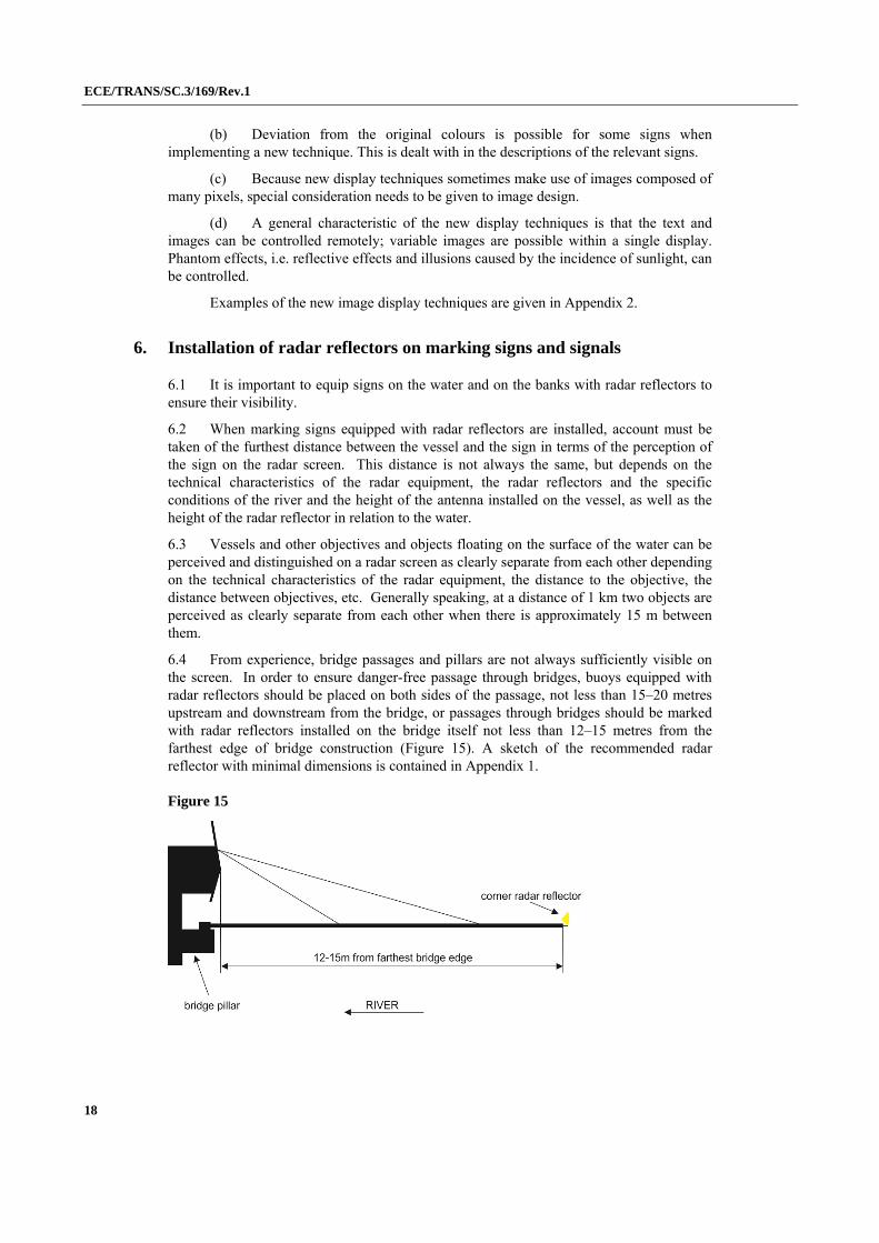
6.4 From experience, bridge passages and pillars are not always sufficiently visible on the screen. In order to ensure danger-free passage through bridges, buoys equipped with radar reflectors should be placed on both sides of the passage, not less than 15–20 metres upstream and downstream from the bridge, or passages through bridges should be marked with radar reflectors installed on the bridge itself not less than 12–15 metres from the farthest edge of bridge construction (Figure 15). A sketch of the recommended radar reflector with minimal dimensions is contained in Appendix 1.
Figure 15
ECE/TRANS/SC.3/169/Rev.1
19
6.5 Since radar reflectors are extremely reliable, every effort should be made to install them by means of supports on the framework of bridges to mark the navigable passage through the bridge.
6.6 Navigational hazards and water supply engineering structures (sunken vessels, groynes, cross-beams, etc.) located in the river bed may also be marked by signs equipped with radar reflectors. If the groynes or cross-beams marked by radar reflector signals are located along one of the banks while the fairway follows the opposite bank, which is low and flat, the radar reflector signals may also be placed on that bank so as to facilitate the orientation of vessels navigating by radar.
6.7 In general, when radar reflectors are used on marking signs and signals, the rule that these reflectors shall not modify the form or size of the sign or signal should be observed. Their colour shall also correspond to the colour of the sign or signal in question.
6.8 The most common type of radar reflector is the so-called square octahedral reflector, i.e. a reflector with eight cavities. It is constructed of 3 flat square plates perpendicular to one another. The reflectors should be made of aluminium or stainless steel, and not painted so as to enhance reflectivity.
6.9 Practical experience has shown that there is a need for at least two standard sizes of reflectors on buoys and markers. Recommended dimensions are as follows:
type 1: tip to tip height 420 mm
type 2: tip to tip height 850 mm
6.10 The square plate referred to above has a diagonal of 300 or 600 mm respectively and sides of 210 or 425 mm respectively. The reflector should be placed in the lying position to maximize its reflectivity. A sketch of the reflector is contained in Appendix 1.

ECE/TRANS/SC.3/169/Rev.1
20
Appendix 1
Minimal dimensions of the signs from annex 7 and 8 of the European Code for Inland Waterways
For Appendix 1, please consult www.unece.org/trans/main/sc3/sc3res.html.
ECE/TRANS/SC.3/169/Rev.1
21
Appendix 2
New Image Display Techniques
A. Light guide technology
Light guide technology, is mostly familiar from the matrix signalling devices positioned above roads. The images are displayed on lens arrays, linked by means of fibre optics (glass or plastic cable) to an optical device with, usually, a main and a back-up light. Every image is controlled from one or more optical devices. By switching the different optical devices on and off, different images, and therefore variable information, can be displayed.
Advantages:
(a) no mechanical/moving parts; (b) low maintenance; (c) high luminous intensity (adjustable); (d) high-fidelity imaging; (e) all-weather; (f) socket can be located accessibly.
Disadvantages:
(a) relatively costly; (b) limited number of images.
B. Light emitting diode (LED)
A LED is a small low voltage light source. Its visibility is limited by its angular aperture and the luminance of the LEDs. Images are made up of a large number of LEDs, each controlled separately. In other respects its properties are very similar to those of light guide technology.
Advantages:
(a) no mechanical/moving parts; (b) low maintenance; (c) simple control; (d) high-fidelity imaging.
Disadvantages:
(a) limited range of display colours; (b) light output affected by ambient temperature.
C. Electromagnetic segmented display
Any desired image can be displayed by reversing electromagnetic segments, one side of which is light and the other dark in colour. The angular aperture on these displays is wide, both horizontally and vertically.

ECE/TRANS/SC.3/169/Rev.1
22
Advantages:
(a) presentational flexibility; (b) displays in all colours; (c) easy to read; (d) low energy usage; (e) continues to display last image if power fails.
Disadvantages:
(a) displays must normally be kept in a conditioned cabinet because of moving parts; (b) lighting required when dark.
D. Rotary drum display
Rotary drum displays are suitable for displaying regularly changing configurations.
Advantages:
(a) Inland Waterways Police Regulations (IWPR) configuration can be accurately reproduced; (b) displays in all colours; (c) good visibility.
Disadvantages:
(a) mechanical parts, so maintenance facilities are necessary; (b) number of images limited; (c) lighting required when dark.
E. Moving screens
Moving screens can consist of a display with a large number of light dots (LED or bipolar segments), switched so as to form the arbitrary texts or diagrams. The text can also move, allowing a message of virtually unlimited length to be displayed.
Advantages:
(a) flexible, unlimited displays; (b) no moving parts; (c) all-weather.
Disadvantages:
(a) monochrome; (b) relatively expensive.
Application: information on waiting times, operating times, etc.