guidelines for verification of damage stability ... · recommendation entitled guideline for scope...
TRANSCRIPT
For reasons of economy, this document is printed in a limited number. Delegates are kindly asked to bring their copies to meetings and not to request additional copies.
I:\SLF\52\INF-4.doc
INTERNATIONAL MARITIME ORGANIZATION
IMO
E
SUB-COMMITTEE ON STABILITY AND LOAD LINES AND ON FISHING VESSELS SAFETY 52nd session Agenda item 9
SLF 52/INF.420 November 2009ENGLISH ONLY
GUIDELINES FOR VERIFICATION OF DAMAGE STABILITY REQUIREMENTS
FOR TANKERS AND BULK CARRIERS
Guideline for scope of damage stability verification on new oil tankers, chemical tankers and gas carriers
Submitted by the International Association of Classification Societies (IACS)
SUMMARY Executive summary:
This document provides at annex an IACS Guideline for Scope of Damage Stability Verification on new oil tankers, chemical tankers, and gas carriers
Strategic direction:
2
High-level action:
2.1.1
Planned output:
2.1.1.5
Action to be taken:
Paragraph 6
Related document:
SLF 51/17, paragraph 13.3.5
Background 1 Following extensive debate at SLF 51, the Sub-Committee noted IACS’s intention to submit the approval procedures used by its members for damage stability calculations to SLF 52, should they be requested (document SLF 51/17, paragraph 13.3.5). 2 After SLF 51, the Chairman of the Sub-Committee invited IACS to provide the information on the scope of damage stability verification uniformly applied by its members to SLF 52. Discussion 3 In response to the request referred to in paragraph 2 above, IACS has developed a recommendation entitled Guideline for scope of damage stability verification on new oil tankers, chemical tankers and gas carriers, which provides a guideline to obtain a reference uniform approach for verifying damage stability under the following IMO instruments: SOLAS, ICLL, MARPOL Annex I, IBC Code and IGC Code.
SLF 52/INF.4 - 2 -
I:\SLF\52\INF-4.doc
4 The relevant regulations of existing IMO instruments (i.e. conventions, codes, guidelines and circulars) and IACS resolutions (i.e. Procedural Requirements, Unified Requirements, Unified Interpretations, etc.) applicable to the damage stability of new oil tankers, chemical tankers and gas carriers were considered in the development of this recommendation. 5 A copy of the approved IACS Recommendation No.110 is provided at the annex to this document. Action requested of the Sub-Committee 6 The Sub-Committee is invited to note the above and the IACS Recommendation provided at the annex to this document.
***
SLF 52/INF.4
I:\SLF\52\INF-4.doc
ANNEX
No.110 (Nov. 2009)
Guideline for Scope of Damage Stability Verification on new oil tankers, chemical tankers and gas carriers 1. Application This recommendation applies for new oil tankers, chemical tankers and gas
carriers contracted for construction on or after 1st January 2010 subject to review of impact on ships undergoing approval and delivering after said date.
2. Reference
2.1 IMO Instruments:
2.1.1 General Instruments: SOLAS Chapter II-1, Regulations 4.1, 4.2, 5-1 and 19;
Res. MSC.143(77) "Adoption of amendments to the Protocol of 1988 relating to the International Convention on Load Lines, 1966", Regulations 27(2), 27(3), 27(11), 27(12) and 27(13)1;
Res. MSC.281(85) "Explanatory Notes to the SOLAS Chapter II-1 Subdivision and Damage Stability Regulations" - special attention should be paid to Guidelines for the Preparation of Subdivision and Damage Stability Calculations specified in the Appendix;
Res. MSC.245(83) "Recommendation on a Standard Method for Evaluating Cross-Flooding Arrangements";
MSC.1/Circ.1245 "Guidelines for Damage Control Plans and Information to the Master"; and
MSC.1/Circ.1229 "Guidelines for the Approval of Stability Instruments", paragraph 4.
2.1.2 Instrument applicable to oil tankers: MARPOL Annex I, Regulations 28.
2.1.3 Instruments applicable to gas carriers: International Code for the Construction and Equipment of Ships Carrying
Liquefied Gases in Bulk (IGC Code), Chapter 2, Paragraphs 2.1, 2.4, 2.5, 2.6.2, 2.6.3, 2.7, 2.8 and 2.9; and
MSC/Circ.406/Rev.1 "Guidelines on Interpretation of the International Code for the Construction and Equipment of Ships Carrying Dangerous Chemicals in Bulk (IBC Code) and the International Code for the Construction and Equipment of Ships Carrying Liquefied Gases in Bulk (IGC Code) and Guidelines for the Uniform Application of the Survival Requirements of the IBC and IGC Codes".
1 The application of ICLL Protocol 1988, Reg.27 is explained in Annex 1.
SLF 52/INF.4 ANNEX Page 2
I:\SLF\52\INF-4.doc
2.1.4 Instruments applicable to chemical tankers: International Code for the Construction and Equipment of Ships Carrying
Dangerous Chemicals in Bulk (IBC Code), Chapter 2, Paragraphs 2.1, 2.4, 2.5, 2.6.2, 2.7, 2.8 and 2.9; and
MSC/Circ.406/Rev.1 “Guidelines on Interpretation of the International Code for the Construction and Equipment of Ships Carrying Dangerous Chemicals in Bulk (IBC Code) and the International Code for the Construction and Equipment of Ships Carrying Liquefied Gases in Bulk (IGC Code) and Guidelines for the Uniform Application of the Survival Requirements of the IBC and IGC Codes”.
2.2 IACS Resolutions: UR L5 (Corr.1 Nov 2006) “Onboard Computers for Stability Calculations”; PR7 (Rev.5.1 May 2006) “Procedure for the Training and Qualification of
Survey and Plan Approval Staff”; and UI SC 156 (June 2002) “Doors in watertight bulkheads of cargo ships and
passenger ships. 3. General 3.1 Education and training 3.1.1 Plan approval staff engaged in damage stability verification of new oil
tankers, chemical tankers and gas carriers should have as minimum the following formal educational background: - a degree or equivalent from a tertiary institution recognized within the
field of marine engineering or naval architecture; and - competent in the English language commensurate with their work. 3.1.2 Plan approval staff engaged in damage stability verification of new oil tankers, chemical tankers and gas carriers should be trained according to theoretical and practical modules defined by the Society to acquire and develop general knowledge and understanding applicable to the a/m types of ship and stability assessment according to the Society Rules and Instruments and Resolutions referred in paragraph 2 above.
3.1.3 Methods of training may include monitoring, testing, etc. on regular basis according to the Society’s system. Evidence of training provided should be documented.
3.1.4 Updating of qualification may be done through the following methods: - self-study; - extraordinary seminars in case of significant changes in the Society’s
Rules or International Conventions, Codes, etc.; and - special training on specific work, which is determined by a long
absence of practical experience. Maintenance of qualification should be verified at annual performance review.
3.2 Scope of stability verification The scope of damage stability verification is determined by the required damage
stability standards (applicable damage stability criteria) and aims at providing the ship’s master with a sufficient number of approved loading conditions to be
SLF 52/INF.4 ANNEX
Page 3
I:\SLF\52\INF-4.doc
used for the loading of the ship. In general, for non approved loading conditions (by the Administration or RO), KG/GM limit curve(s) or approved loading instrument software, satisfying the stability requirements (intact and damage) for the draught range to be covered should be used.
Within the scope of the verification determined as per the above, all potential or necessary damage conditions should be determined taking into account the damage stability criteria.
Damage stability verification involves a review of submitted calculations and supporting documentation with independent check calculations to confirm compliance with relevant stability criteria. In addition, the verification may also involve approval of damage stability calculation results which may include the approval of the loading instrument software.
The examination and approval of the loading instrument software installed on board and to be used for assessing damage stability should also be carried out. A loading instrument comprises hardware and software. The accuracy of the computation results and actual ship data used by the software is to be verified.
3.3 Assumptions For all loading conditions, the initial metacentric height and the righting lever
curve should be corrected for the effect of free surfaces of liquids in tanks. Superstructures and deckhouses not regarded as enclosed can be taken into
account in stability calculations up to the angle at which their openings are flooded.
When determining the righting lever (GZ) of the residual stability curve, the constant displacement (lost buoyancy) method of calculation should be used (see paragraph 6.1).
Conditions of loading and instructions provided by the submitter for use of the applicable KG/GM limit curve(s) and variation of loading patterns and representative cargoes are taken to be representative of how the ship will be operated.
3.4 Documentation to be submitted for review 3.4.1 Presentation of documents The documentation should begin with the following details: principal
dimensions, ship type, designation of intact conditions, designation of damage conditions and pertinent damaged compartments, KG/GM limit curve(s).
3.4.2 General documents and supporting information: .1 lines plan, plotted or numerically;
.2 hydrostatic data and cross curves of stability (including drawing of the buoyant hull);
.3 definition of watertight compartments with moulded volumes, centres of gravity and permeability;
.4 layout plan (watertight integrity plan) for the watertight compartments with all internal and external opening points including their connected sub-compartments, and particulars used in measuring the spaces, such as general arrangement plan and tank plan;
SLF 52/INF.4 ANNEX Page 4
I:\SLF\52\INF-4.doc
.5 Stability booklet/Loading manual including at least fully loaded homogeneous condition at summer load line draught (departure and arrival) and other intended operational conditions;
.6 coordinates of opening points with their level of tightness (e.g., weathertight, unprotected) 2, including reference to the compartment that the opening is connected to.
.7 watertight door location;
.8 cross and down flooding devices and the calculations thereof according to resolution MSC.245(83) with information about diameter, valves, pipe lengths and coordinates of inlet/outlet. Cross/down flooding should not be considered for the purpose of achieving compliance with the stability criteria (see also paragraph 9.2);
.9 pipes in damaged area when the breaching of these pipes results in progressive flooding (see paragraph 10.1); and
.10 damage extents and definition of damage cases.
3.4.3 Special documents: .1 Documentation
Design documentation: damage stability calculations (including residual stability curves), the arrangements, configuration and contents of the damaged compartments, and the distribution, relative densities and the free surface effect of liquids.
Operational documentation: loading and stability information booklet (stability booklet), Damage Control Plan; and Damage Control Booklet 2.
.2 Special consideration For intermediate conditions, as stages before cross-flooding or before
progressive flooding, an appropriate scope of the documentation covering the aforementioned items is needed in addition. The intermediate stages for cargo outflow and sea water inflow should be considered only in case where it is obviously that there is some risk to achieve critical trim or/and stability parameters in the intermediate stages.
4. Operating Limits – Descriptions/Assumptions In considering the scope of the verification to be conducted, consideration of the operating limits is needed.
2 Details of watertight, weathertight and unprotected openings should be included in the Damage Control
Plan and Damage Control Booklet in accordance with MSC.1/Circ.1245.
The cases and extent of progressive flooding assumed in the damage stability analysis should be indicated in the Damage Control Booklet and the Documents for Submission in accordance with the Appendix to MSC.281(85). Arrangements to prevent further flooding are to be indicated on the Damage Control Plan and in the Damage Control Booklet.
SLF 52/INF.4 ANNEX
Page 5
I:\SLF\52\INF-4.doc
The following loading options should be permitted: a) Service loading conditions identical to the approved loading conditions of the
stability booklet (see paragraph 4.2); or b) Service loading conditions complying with the approved intact and damage
stability limiting curves (where provided) (see paragraph 4.3); or c) Service loading conditions which have been checked with an approved on-board
stability software with the capability to perform damage stability calculations (Type 2 or 3 of IACS URL5, Rev.2, Corr.1) either based on KG/GM limit curve(s) or based on direct damage stability assessment (see paragraph 4.5).
If above mentioned proof of compliance is not possible, then the intended loading conditions should be either prohibited or be submitted for specific approval to the Administration or RO. Suitable instructions to this effect should be included in the stability booklet/loading manual. 4.1 Specific loading patterns Ship specific design loading patterns and loading restrictions should be clearly displayed in the stability booklet. The following items should be included: a) Any intended symmetrical/unsymmetrical, homogeneous/alternate or
ballast/partial/full loading conditions; b) Types (oil, NLS and/or LNG) of liquid cargo allowed to be carried; c) Restrictions to different liquid loads to be carried simultaneously; d) Range of permissible densities of liquid loads to be carried; e) Minimum fillings, if stability is critical (i.e. at least one of calculated stability
parameters is equal to the limit specified in stability criteria applicable to the vessel) for several intact or damage cases; and
f) Permissible loading conditions, patterns of loading, loading/unloading sequences, etc., particularly corresponding to multiple freeboards when so assigned to the vessel.
4.2 Matrix of permissible loading conditions In the absence of stability software and KG/GM limit curve(s), in lieu of approved specific loading conditions, a matrix clearly listing the allowable range of loading parameters (draft, trim, KG, cargo loading pattern and SG) that the vessel is allowed to load in order to be in compliance with the applicable intact and damage stability criteria can be developed for the stability booklet when a greater degree of flexibility than that afforded by approved specific loading conditions is needed. 4.3 KG/GM Limit Curve(s) The preparation of KG/GM limit curves for tank vessels, especially for gas/chemical tank vessels, should include a comprehensive calculation as described in MSC/Circ.406/Rev.1, paragraph 2.1: “A systematic investigation of damage survival characteristics should be undertaken by making calculations to obtain the minimum required GM or Maximum allowable KG at a sufficient number of draughts within the operating range to permit the construction of a series of curves of “required GM” or “allowable KG” in relation to draught and cargo tank content in way of the damage. The curves must be sufficiently comprehensive to cover operational trim requirements.”
SLF 52/INF.4 ANNEX Page 6
I:\SLF\52\INF-4.doc
The verification of KG/GM limit curves should be conducted without any free surface correction. The actual loading condition uses the free surface correction (see paragraph 6.5) when comparing actual and allowable KG values. It is to be noted that any change of filling level, draught, trim, cargo density might have a major influence to the results of a damage case; therefore the following items should be considered carefully for the calculation of the KG/GM limit curves: a) Intact and damage stability criteria applicable to the vessel; b) The maximum required damage extent and lesser extents of damage which
provide the most severe damage cases; c) Draught range of the vessel (up to tropical freeboard if required); d) Trim range of the vessel (see paragraph 6.6); e) Full and empty cargo tanks; f) Partially filled cargo tanks (consideration of increments as necessary); g) Minimum tank fillings in tons if required; h) Maximum/minimum densities of cargoes; and i) Ballast tank filling levels as necessary to achieve compliance. Damage stability calculations, on which the KG/GM limit curve(s) is(are) based, should be performed at the design stage. The KG/GM limit curve(s) drawn out taking stability criteria (intact and damage) into account should be inserted in the stability booklet. 4.4 Initial heel The stability booklet should contain a note for the master to avoid initial heel greater than 1 degree. A steady heeling angle may have major influence to the stability of the vessel especially in case of damage. 4.5 Direct calculation onboard (Stability software) The use of stability software for stability calculations is not a class requirement. However, stability software installed onboard should cover all stability requirements (intact and damage) applicable to the ship. The following types of stability softwares, if approved by a classification society, (according to IACS URL5, Rev.2) are applicable for calculation of service loading conditions for tank vessels: a) Type 2: Checking intact and damage stability on basis of a KG/GM limit curve(s)
or previously approved loading conditions; and b) Type 3: Checking intact and damage stability by direct application of
pre-programmed damage cases for each loading condition, including capability for calculation of intermediate damage stages.
The software should be approved by the classification society. The software is not a substitute for the approved stability documentation, but used as a supplement to facilitate stability calculations.
Sufficient damages, taking into account lesser damages, and variation of draft, cargo density, tank loading patterns and extents of tank filling should be performed to ensure that for any possible loading condition the most onerous damages have been examined according to relevant stability criteria.
SLF 52/INF.4 ANNEX
Page 7
I:\SLF\52\INF-4.doc
The methodologies for determining compliance with relevant stability criteria should be as set out in these guidelines.
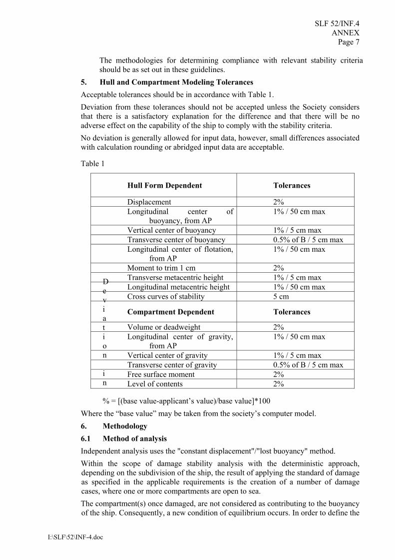
5. Hull and Compartment Modeling Tolerances Acceptable tolerances should be in accordance with Table 1. Deviation from these tolerances should not be accepted unless the Society considers that there is a satisfactory explanation for the difference and that there will be no adverse effect on the capability of the ship to comply with the stability criteria. No deviation is generally allowed for input data, however, small differences associated with calculation rounding or abridged input data are acceptable.
Table 1
Deviation in % = [(base value-applicant’s value)/base value]*100
Where the “base value” may be taken from the society’s computer model. 6. Methodology 6.1 Method of analysis Independent analysis uses the "constant displacement"/"lost buoyancy" method. Within the scope of damage stability analysis with the deterministic approach, depending on the subdivision of the ship, the result of applying the standard of damage as specified in the applicable requirements is the creation of a number of damage cases, where one or more compartments are open to sea. The compartment(s) once damaged, are not considered as contributing to the buoyancy of the ship. Consequently, a new condition of equilibrium occurs. In order to define the
Hull Form Dependent Tolerances
Displacement 2% Longitudinal center of
buoyancy, from AP 1% / 50 cm max
Vertical center of buoyancy 1% / 5 cm max Transverse center of buoyancy 0.5% of B / 5 cm max Longitudinal center of flotation,
from AP 1% / 50 cm max
Moment to trim 1 cm 2% Transverse metacentric height 1% / 5 cm max Longitudinal metacentric height 1% / 50 cm max Cross curves of stability 5 cm
Compartment Dependent Tolerances
Volume or deadweight 2% Longitudinal center of gravity,
from AP 1% / 50 cm max
Vertical center of gravity 1% / 5 cm max Transverse center of gravity 0.5% of B / 5 cm max Free surface moment 2% Level of contents 2%
SLF 52/INF.4 ANNEX Page 8
I:\SLF\52\INF-4.doc
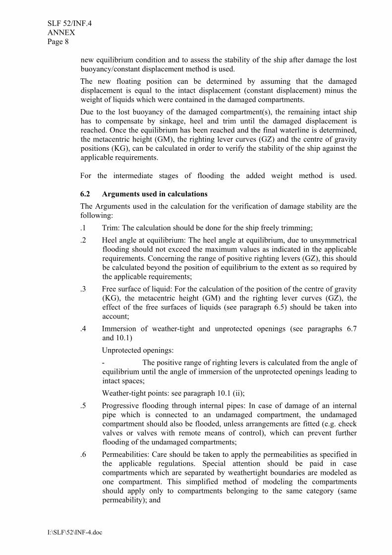
new equilibrium condition and to assess the stability of the ship after damage the lost buoyancy/constant displacement method is used. The new floating position can be determined by assuming that the damaged displacement is equal to the intact displacement (constant displacement) minus the weight of liquids which were contained in the damaged compartments. Due to the lost buoyancy of the damaged compartment(s), the remaining intact ship has to compensate by sinkage, heel and trim until the damaged displacement is reached. Once the equilibrium has been reached and the final waterline is determined, the metacentric height (GM), the righting lever curves (GZ) and the centre of gravity positions (KG), can be calculated in order to verify the stability of the ship against the applicable requirements. For the intermediate stages of flooding the added weight method is used. 6.2 Arguments used in calculations The Arguments used in the calculation for the verification of damage stability are the following: .1 Trim: The calculation should be done for the ship freely trimming; .2 Heel angle at equilibrium: The heel angle at equilibrium, due to unsymmetrical
flooding should not exceed the maximum values as indicated in the applicable requirements. Concerning the range of positive righting levers (GZ), this should be calculated beyond the position of equilibrium to the extent as so required by the applicable requirements;
.3 Free surface of liquid: For the calculation of the position of the centre of gravity (KG), the metacentric height (GM) and the righting lever curves (GZ), the effect of the free surfaces of liquids (see paragraph 6.5) should be taken into account;
.4 Immersion of weather-tight and unprotected openings (see paragraphs 6.7 and 10.1)
Unprotected openings: - The positive range of righting levers is calculated from the angle of
equilibrium until the angle of immersion of the unprotected openings leading to intact spaces;
Weather-tight points: see paragraph 10.1 (ii); .5 Progressive flooding through internal pipes: In case of damage of an internal
pipe which is connected to an undamaged compartment, the undamaged compartment should also be flooded, unless arrangements are fitted (e.g. check valves or valves with remote means of control), which can prevent further flooding of the undamaged compartments;
.6 Permeabilities: Care should be taken to apply the permeabilities as specified in the applicable regulations. Special attention should be paid in case compartments which are separated by weathertight boundaries are modeled as one compartment. This simplified method of modeling the compartments should apply only to compartments belonging to the same category (same permeability); and
SLF 52/INF.4 ANNEX
Page 9
I:\SLF\52\INF-4.doc
.7 Heel angles for the calculation of the GZ curve: Evaluation of damage stability criteria should generally be determined from data calculated over a range of angles from 0 to 60 degrees. It is recommended to use an increment not exceeding 5 degrees.
6.3 Adjustments for cargo run-off .1 In cases where the damage involves the cargo hold, it is assumed that cargo is
flowing out and that water starts to ingress. During the intermediate stages of flooding it is considered that both cargo and sea water are existing in the damaged tank (see paragraph 9.3).
At the final stage it is assumed that the cargo is completely lost and that the tank is filled with sea water up to the level of the waterline.
.2 The impact on the stability of the ship, due to the inflow and outflow of liquid cargo is also dependent on the following parameters: - the density of the cargo: Liquid cargo with density greater than 0.95 t/m3
should be considered as heavy liquid cargo. In case of lesser vertical extent of damage, i.e. damage above the tank top (see Annex 4), the release of heavy liquid cargo might lead to large angle of heel on the intact side of the ship. Depending on intact draught and cargo tank filling level, outflow of cargo of lesser density may also cause heel to the opposite side; and
- the permeability of the cargo space, taking into account that permeabilities smaller than the those specified in the applicable rules can be applied if justified.
6.4 Handling of permeabilities .1 Permeability of a space means the ratio of the volume within that space, which
should be assumed to be occupied by water to the total volume of that space. The total volume should be calculated to moulded lines and no reduction in total volume should be taken into account due to structural members (i.e. stiffeners, etc.). Account of structural members is taken in the applicable permeabilities (see also MSC/Circ.406/Rev.1, paragraph 3.11).
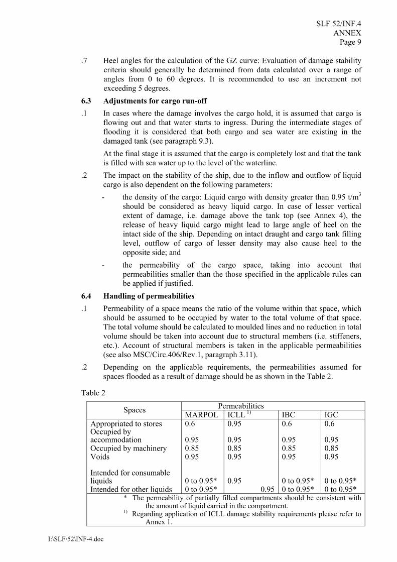
.2 Depending on the applicable requirements, the permeabilities assumed for spaces flooded as a result of damage should be as shown in the Table 2.
Table 2 Permeabilities Spaces MARPOL ICLL 1) IBC IGC
Appropriated to stores 0.6 0.95 0.6 0.6 Occupied by accommodation 0.95 0.95 0.95 0.95 Occupied by machinery 0.85 0.85 0.85 0.85 Voids 0.95 0.95 0.95 0.95
Intended for consumable liquids 0 to 0.95* 0.95 0 to 0.95* 0 to 0.95* Intended for other liquids 0 to 0.95* 0.95 0 to 0.95* 0 to 0.95*
* The permeability of partially filled compartments should be consistent with the amount of liquid carried in the compartment.
1) Regarding application of ICLL damage stability requirements please refer to Annex 1.
SLF 52/INF.4 ANNEX Page 10
I:\SLF\52\INF-4.doc
.3 Whenever damage penetrates a tank containing liquids, it should be assumed that the contents are completely lost from that compartment and replaced by sea water up to the level of the final plane of equilibrium.
.4 Other figures for permeability may be used for the damaged case both during cargo run-off and the final equilibrium condition under the following provisions:
.4.1 The detailed calculations and the arguments used for determining the permeability of the compartment(s) in question, is to be included in the damage stability booklet;
.4.2 The water tightness/resistance to water pressure and the means by which internal fittings/material are secured to the tank should substantiate the use of such fittings/material in reducing the permeability of a compartment. Where a ship is fitted with significant quantities of cargo insulation, the permeabilities of the relevant cargo spaces and/or the void spaces surrounding such cargo spaces may be calculated by excluding the volume of insulation material in those spaces from the flooded volume, provided that the insulating material is shown to comply with the following conditions:
.1 it is impermeable to water under hydrostatic pressure at least corresponding to the pressure caused by the assumed flooding;
.2 it will not crush or break up due to hydrostatic pressure at least corresponding to the pressure caused by the assumed flooding;
.3 it will not deteriorate or change its properties over the long term in the environment anticipated in the space it is installed;
.4 it is highly resistant to the action of hydrocarbons, where relevant; and
.5 it will be adequately secured so that it will remain in position if subjected to collision damage and consequent displacement, distortion of its supporting and retaining structure, repeated rapid ingress and outflow of seawater and the buoyant forces caused by immersion following flooding;
.4.3 The applied permeability should reflect the general conditions of the ship throughout its service life, rather than specific loading conditions; and
.4.4 Permeabilities other than those indicated in Table 2 should be considered only in cases, where it is evident that there is a significant discrepancy between the values shown in the regulations and the actual values (i.e. due to specific tank structure or insulating material).
6.5 Free-surface calculation (upright, as vessel heels and after cargo run-off) With respect to the approval of actual loading conditions the following should
be applied: .1 The free surfaces of liquids lead to the reduction of the centre of gravity (KG),
the metacentric height (GM) and the righting arm (GZ curve) of the ship. Therefore corrections should be made, taking into account the change of the center of gravity of the ship due to the moving of the center of gravity of the liquids.
SLF 52/INF.4 ANNEX Page 11
I:\SLF\52\INF-4.doc
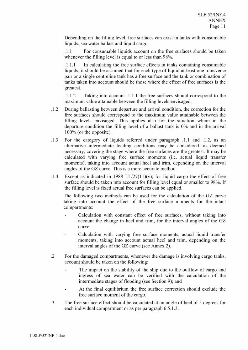
Depending on the filling level, free surfaces can exist in tanks with consumable liquids, sea water ballast and liquid cargo.
.1.1 For consumable liquids account on the free surfaces should be taken whenever the filling level is equal to or less than 98%.
.1.1.1 In calculating the free surface effects in tanks containing consumable liquids, it should be assumed that for each type of liquid at least one transverse pair or a single centreline tank has a free surface and the tank or combination of tanks taken into account should be those where the effect of free surfaces is the greatest.
.1.1.2 Taking into account .1.1.1 the free surfaces should correspond to the maximum value attainable between the filling levels envisaged.
.1.2 During ballasting between departure and arrival condition, the correction for the free surfaces should correspond to the maximum value attainable between the filling levels envisaged. This applies also for the situation where in the departure condition the filling level of a ballast tank is 0% and in the arrival 100% (or the opposite).
.1.3 For the category of liquids referred under paragraph .1.1 and .1.2, as an alternative intermediate loading conditions may be considered, as deemed necessary, covering the stage where the free surfaces are the greatest. It may be calculated with varying free surface moments (i.e. actual liquid transfer moments), taking into account actual heel and trim, depending on the interval angles of the GZ curve. This is a more accurate method.
.1.4 Except as indicated in 1988 LL/27(11)(v), for liquid cargo the effect of free surface should be taken into account for filling level equal or smaller to 98%. If the filling level is fixed actual free surfaces can be applied.
The following two methods can be used for the calculation of the GZ curve taking into account the effect of the free surface moments for the intact compartments: - Calculation with constant effect of free surfaces, without taking into
account the change in heel and trim, for the interval angles of the GZ curve.
- Calculation with varying free surface moments, actual liquid transfer moments, taking into account actual heel and trim, depending on the interval angles of the GZ curve (see Annex 2).
.2 For the damaged compartments, whenever the damage is involving cargo tanks, account should be taken on the following: - The impact on the stability of the ship due to the outflow of cargo and
ingress of sea water can be verified with the calculation of the intermediate stages of flooding (see Section 9); and
- At the final equilibrium the free surface correction should exclude the free surface moment of the cargo.
.3 The free surface effect should be calculated at an angle of heel of 5 degrees for each individual compartment or as per paragraph 6.5.1.3.
SLF 52/INF.4 ANNEX Page 12
I:\SLF\52\INF-4.doc
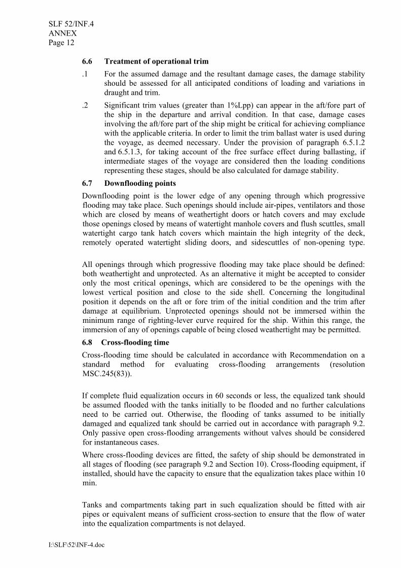
6.6 Treatment of operational trim .1 For the assumed damage and the resultant damage cases, the damage stability
should be assessed for all anticipated conditions of loading and variations in draught and trim.
.2 Significant trim values (greater than 1%Lpp) can appear in the aft/fore part of the ship in the departure and arrival condition. In that case, damage cases involving the aft/fore part of the ship might be critical for achieving compliance with the applicable criteria. In order to limit the trim ballast water is used during the voyage, as deemed necessary. Under the provision of paragraph 6.5.1.2 and 6.5.1.3, for taking account of the free surface effect during ballasting, if intermediate stages of the voyage are considered then the loading conditions representing these stages, should be also calculated for damage stability.
6.7 Downflooding points Downflooding point is the lower edge of any opening through which progressive flooding may take place. Such openings should include air-pipes, ventilators and those which are closed by means of weathertight doors or hatch covers and may exclude those openings closed by means of watertight manhole covers and flush scuttles, small watertight cargo tank hatch covers which maintain the high integrity of the deck, remotely operated watertight sliding doors, and sidescuttles of non-opening type. All openings through which progressive flooding may take place should be defined: both weathertight and unprotected. As an alternative it might be accepted to consider only the most critical openings, which are considered to be the openings with the lowest vertical position and close to the side shell. Concerning the longitudinal position it depends on the aft or fore trim of the initial condition and the trim after damage at equilibrium. Unprotected openings should not be immersed within the minimum range of righting-lever curve required for the ship. Within this range, the immersion of any of openings capable of being closed weathertight may be permitted. 6.8 Cross-flooding time Cross-flooding time should be calculated in accordance with Recommendation on a standard method for evaluating cross-flooding arrangements (resolution MSC.245(83)). If complete fluid equalization occurs in 60 seconds or less, the equalized tank should be assumed flooded with the tanks initially to be flooded and no further calculations need to be carried out. Otherwise, the flooding of tanks assumed to be initially damaged and equalized tank should be carried out in accordance with paragraph 9.2. Only passive open cross-flooding arrangements without valves should be considered for instantaneous cases. Where cross-flooding devices are fitted, the safety of ship should be demonstrated in all stages of flooding (see paragraph 9.2 and Section 10). Cross-flooding equipment, if installed, should have the capacity to ensure that the equalization takes place within 10 min. Tanks and compartments taking part in such equalization should be fitted with air pipes or equivalent means of sufficient cross-section to ensure that the flow of water into the equalization compartments is not delayed.
SLF 52/INF.4 ANNEX Page 13
I:\SLF\52\INF-4.doc
Spaces which are linked by ducts of a large cross-sectional area may be considered to be common, i.e. the flooding of these spaces should be interpreted as instantaneous flooding with the equalization of duration of less than 60 seconds.
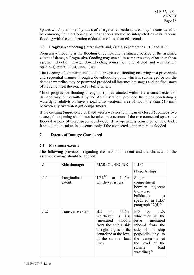
6.9 Progressive flooding (internal/external) (see also paragraphs 10.1 and 10.2) Progressive flooding is the flooding of compartments situated outside of the assumed extent of damage. Progressive flooding may extend to compartments, other then those assumed flooded, through downflooding points (i.e. unprotected and weathertight openings), pipes, ducts, tunnels, etc. The flooding of compartment(s) due to progressive flooding occurring in a predictable and sequential manner through a downflooding point which is submerged below the damage waterline may be permitted provided all intermediate stages and the final stage of flooding meet the required stability criteria. Minor progressive flooding through the pipes situated within the assumed extent of damage may be permitted by the Administration, provided the pipes penetrating a watertight subdivision have a total cross-sectional area of not more than 710 mm2 between any two watertight compartments. If the opening (unprotected or fitted with a weathertight mean of closure) connects two spaces, this opening should not be taken into account if the two connected spaces are flooded or none of these spaces are flooded. If the opening is connected to the outside, it should not be taken into account only if the connected compartment is flooded. 7. Extents of Damage Considered 7.1 Maximum extents The following provisions regarding the maximum extent and the character of the assumed damage should be applied:
.1 Side damage: MARPOL /IBC/IGC ILLC
(Type A ships)
.1.1 Longitudinal extent:
1/3L2/3 or 14.5m, whichever is less
Single compartment between adjacent transverse bulkheads as specified in ILLC paragraph 12(d) 1)
.1.2 Transverse extent: B/5 or 11.5m, whichever is less (measured inboard from the ship’s side at right angles to the centreline at the level of the summer load line)
B/5 or 11.5, whichever is the lesser (measured inboard from the side of the ship perpendicularly to the centerline at the level of the summer load waterline) 1)
SLF 52/INF.4 ANNEX Page 14
I:\SLF\52\INF-4.doc
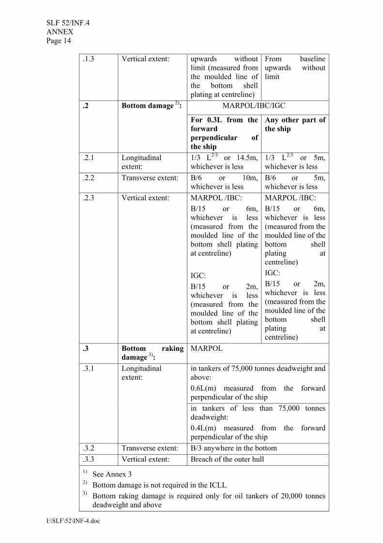
.1.3 Vertical extent: upwards without limit (measured from the moulded line of the bottom shell plating at centreline)
From baseline upwards without limit
MARPOL/IBC/IGC .2 Bottom damage 2): For 0.3L from the
forward perpendicular of the ship
Any other part of the ship
.2.1 Longitudinal extent:
1/3 L2/3 or 14.5m, whichever is less
1/3 L2/3 or 5m, whichever is less
.2.2 Transverse extent: B/6 or 10m, whichever is less
B/6 or 5m, whichever is less
.2.3 Vertical extent: MARPOL /IBC: B/15 or 6m, whichever is less (measured from the moulded line of the bottom shell plating at centreline)
IGC: B/15 or 2m, whichever is less (measured from the moulded line of the bottom shell plating at centreline)
MARPOL /IBC: B/15 or 6m, whichever is less (measured from the moulded line of the bottom shell plating at centreline) IGC: B/15 or 2m, whichever is less (measured from the moulded line of the bottom shell plating at centreline)
.3 Bottom raking damage 3):
MARPOL
in tankers of 75,000 tonnes deadweight and above: 0.6L(m) measured from the forward perpendicular of the ship
.3.1 Longitudinal extent:
in tankers of less than 75,000 tonnes deadweight: 0.4L(m) measured from the forward perpendicular of the ship
.3.2 Transverse extent: B/3 anywhere in the bottom
.3.3 Vertical extent: Breach of the outer hull 1) See Annex 3 2) Bottom damage is not required in the ICLL 3) Bottom raking damage is required only for oil tankers of 20,000 tonnes
deadweight and above
SLF 52/INF.4 ANNEX Page 15
I:\SLF\52\INF-4.doc
7.2 Lesser extents 7.2.1 If any damage of a lesser extent than the maximum damage specified in 7.1 would result in a more severe condition, such damage should be considered. 7.2.2 In the case of gas carrier, local side damage anywhere in the cargo area extending inboard 760mm measured normal to the hull shell should be considered and transverse bulkheads should be assumed damaged when also required by the applicable subparagraphs of 2.8.1 of the IGC Code. 7.3 Rationale for reviewing lesser extents including symmetrical vs. unsymmetrical tank arrangement/geometry - Calculation on weakest side For a given loading condition, following examples of damages of lesser extent may result in a more severe situation than that caused by a maximum damage specified in 7.1: .1 Example of damage on double bottom tanks with watertight center girder: - Damage of lesser extent which could occur at the bottom plate of the ship,
without damaging the center girder, will lead to flooding of the double bottom tank on one side of the ship only . This is the case of unsymmetrical flooding. For the same location, damage of maximum extent would cause damage on the center girder and therefore flooding of the double bottom tanks on both sides. This is the case of symmetrical flooding. (see Annex 4).
Compared to the symmetrical flooding in the case of maximum damage extent, unsymmetrical flooding of spaces, caused by damage of lesser extent might lead to a more severe situation. Of course, in case of non-watertight center girder, the effect of damage of lesser and maximum extent would be the same. .2 Example of damage with lesser vertical extents: - Damage starting from above a tank top would flood the spaces only above the
double bottom (see Annex 4). This may result in a more onerous residual stability or heeling angle
Taking into account above examples, it is necessary to review damages of lesser extents considering the symmetrical or unsymmetrical nature of tank arrangements of the ship and geometry of the ship. The ship’s damage stability is to be ensured, in the most severe or weakest case of damage of lesser extents. 8. Rationale Applied for Loading Pattern Evaluation For damage stability calculations of tank vessels the following effects due to different loading methods should be taken into account in determining the scope of verification and specific cases of damage to be investigated. 8.1 Homogeneous vs alternate/partial loading For homogeneous loading conditions the damage of cargo tanks may have a major effect on residual stability. Outflow of the loaded cargo liquids (and less inflow of sea water) may reduce the vessels displacement and cause heel to opposite side of the damage. For alternate loading conditions the residual stability depends on the damaged cargo tank. Damage of a fully loaded cargo tank might cause reduction of the initial displacement and heel to the opposite side, but damage on an empty cargo tank might cause the opposite effect. For the damage of two adjacent cargo tanks, one filled and one empty, the total effect might be less severe due to two (partly) neutralizing effects.
SLF 52/INF.4 ANNEX Page 16
I:\SLF\52\INF-4.doc
Partial loading of liquid cargo tanks will cause a high free surface moment when the surface does not intersect with the tank overhead and will increase the heel in case of damage. However, reductions of the initial displacement and heel to the opposite side may not be as significant. Trim to the vessel as consequence of damage can be significant due to many partially filled cargo tanks. 8.2 Symmetrical and unsymmetrical loading pattern For symmetrical load (alternate, homogeneous, full, partial or empty) it is sufficient to perform the damage stability calculation for one side of the ship, if the ship (and all openings) are also symmetrical and initial heel to portside or starboard is zero. For unsymmetrical loads (different opposite liquids, zigzag loading or different filling levels at portside and starboard) a damage stability calculation for both ships sides should be performed. 8.3 MSC/Circ.406, Rev.1 Additional information regarding intact and damage stability matters for tank vessels can be found in MSC/Circ.406/Rev.1 which also recommends application of the “Guidelines for the Uniform Application of the Survival Requirements of the Bulk Chemical Code (BCH Code) and the Gas Carrier Code (GC Code)” to the IBC and IGC codes. 9. Intermediate Stages of Flooding Including Equalization, if any, and Cargo Run-off Intermediate stages of flooding cover the flooding process from the commencement of flooding up to but excluding the final equilibrium damage condition (see also paragraph 3.4.3.2). Intermediate stages should be comprehensively checked for all ships at the design appraisal stage. 9.1 Basis for checking intermediate cases of flooding and Minimum Stability Criteria Applied The stability criteria applicable to the final equilibrium stage should also be satisfied for all intermediate stages. Where stability is not critical (i.e. all of the calculated stability parameters are within the limit specified in the stability criteria applicable to the vessel), calculations need not be submitted for examination. 9.2 Number of intermediate stages considered A sufficient number of intermediate stages should be examined for all damage cases. It is generally recommended to apply 5 intermediate stages of flooding (see also paragraphs 6.8, 6.9 and 10.1). If the vessel is equipped with non-instantaneous (greater than 60 secs) passive equalization arrangements or non-passive equalization arrangements of any size the following procedure is to be used:
SLF 52/INF.4 ANNEX Page 17
I:\SLF\52\INF-4.doc
1) Compliance with the relevant criteria should be demonstrated without using equalisation arrangements for intermediate and final stages; and 2) For subsequent equalisation additional 2 intermediate stages and final stages the compliance should also be demonstrated. 9.3 Cargo outflow and flood water inflow During intermediate flooding stages a practical method of calculating the floating position and residual righting moments is the added mass method where the intact condition is corrected for the weights of inflowing floodwater and outflowing cargo. During each stage an assumed amount of added floodwater and/or cargo outflow should be used. The following method is recommended: i) For a loaded tank an equal loss of liquid cargo mass and equal inflow of floodwater mass at each stage resulting in a total loss of liquid cargo at and total inflow of floodwater to the final damage equilibrium waterline; and ii) For an empty tank an equal inflow of floodwater mass at each stage resulting in total inflow of floodwater to the final damage equilibrium waterline. See Annex 5 for example calculation. Alternative methods may be accepted, for example: i) For a loaded tank the loss of liquid cargo mass and inflow of floodwater mass is based on a linear change of total tank content density over each intermediate stage from pure cargo at the intact condition to pure floodwater at the final damage equilibrium waterline. See Annex 5 for example calculation. ii) For an empty tank an increasing depth of water at each stage based on the difference between the depth of water in the tank and the depth to the waterline in way of the tank, divided by the number of remaining stages, resulting in total inflow of floodwater to the final damage equilibrium waterline. Noting that calculation of stability in the final damage condition assumes both the liquid cargo and the buoyancy of the damaged spaces to be lost it is therefore considered both reasonable and consistent to base the residual GZ curve at each intermediate stage on the intact displacement minus total liquid cargo loss at each stage. 9.4 Treatment of free surface and KG adjustment Taking due account of the requirements of paragraph 6.5.1.1 it is generally recommended to apply actual liquid transfer moments for all tank filling levels in determining compliance with the relevant damage stability criteria through direct calculations of actual loading conditions. With regard to the treatment of free surfaces of flooded spaces and noting that there will be combinations of empty and loaded tanks within the damaged extent all damaged compartments should be considered individually flooded during the intermediate stages – i.e. individual free surfaces. (The compartments are considered open to the sea in the final damage condition).
SLF 52/INF.4 ANNEX Page 18
I:\SLF\52\INF-4.doc
10. Final Stage of Flooding (Resolution MSC.281(85) to be referred to) 10.1 Watertight and weathertight integrity The mandatory instruments referenced in paragraph 2.1 require the final waterline, taking into account sinkage, heel and trim, shall be below the lower edge of any opening through which progressive flooding may take place. Such openings shall include air-pipes (irrespective of closing devices) and those which are closed by means of weathertight doors or hatch covers and may exclude those openings closed by means of watertight manhole covers and flush scuttles, small watertight cargo tank hatch covers which maintain the high integrity of the deck, remotely operated watertight sliding doors, and sidescuttles of the non-opening type. Within the required range of residual stability, the immersion of any of the openings listed above and other openings capable of being closed weathertight may be permitted. ICLL Protocol 88 permits, in the case of doors separating a main machinery space from a steering gear compartment, watertight doors may be of a hinged, quick-acting type kept closed at sea whilst not in use, provided also that the lower sill of such doors is above the summer load waterline. The following exceptions may be permitted as per IACS UI SC 156, unless indicated otherwise by the Administration: i) Watertight doors under the final waterline after flooding Doors under the final waterline after flooding should be remotely operated sliding watertight doors with an exception to doors separating a main machinery space from a steering gear compartment. Hinged water tight doors may be acceptable as an alternative subject to lower frequency of passage through the doors, agreement by flag administration concerned and other additional requirements; ii) Progressive flooding due to damage or submersion of air pipes Progressive flooding may be accepted subject to the air pipes leading to relatively small compartments which are progressively flooded in a predictable and sequential manner in which all intermediate stages of flooding (with the exception on no progressive flooding) and the final stage of flooding meet the required stability criteria; iii) Watertight doors on the aft wall of forecastle under the final waterline after flooding Hinged watertight doors at the aft bulkhead of a forecastle space are permitted to be submerged after damage only when possible progressive flooding is limited to one relatively small compartment which is progressively flooded in a predictable and sequential manner in which all intermediate stages of flooding (with the exception of no progressive flooding) and the final stage of flooding meet the required stability criteria. No further progressive flooding is permitted beyond the initial flooding of the forecastle. This approach is only permitted after all other options, such as increasing the sill height, relocating the door, only providing access from above, have been shown to be unworkable in practice. 10.2 Unprotected openings Residual GZ curves should be terminated at the lowest angle of submersion of an unprotected opening.
SLF 52/INF.4 ANNEX Page 19
I:\SLF\52\INF-4.doc
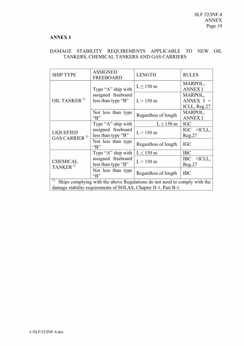
ANNEX 1 DAMAGE STABILITY REQUIREMENTS APPLICABLE TO NEW OIL
TANKERS, CHEMICAL TANKERS AND GAS CARRIERS
SHIP TYPE ASSIGNED FREEBOARD LENGTH RULES
L ≤ 150 m MARPOL, ANNEX I Type “A” ship with
assigned freeboard less than type “B” L > 150 m
MARPOL, ANNEX I + ICLL, Reg.27
OIL TANKER 1)
Not less than type “B” Regardless of length MARPOL,
ANNEX I L ≤ 150 m IGC Type “A” ship with
assigned freeboard less than type “B” L > 150 m IGC +ICLL,
Reg.27 LIQUEFIED GAS CARRIER 1) Not less than type
“B” Regardless of length IGC
L ≤ 150 m IBC Type “A” ship with assigned freeboard less than type “B” L > 150 m IBC +ICLL,
Reg.27 CHEMICAL TANKER 1) Not less than type
“B” Regardless of length IBC 1) Ships complying with the above Regulations do not need to comply with the damage stability requirements of SOLAS, Chapter II-1, Part B-1.
SLF 52/INF.4 ANNEX Page 20
I:\SLF\52\INF-4.doc
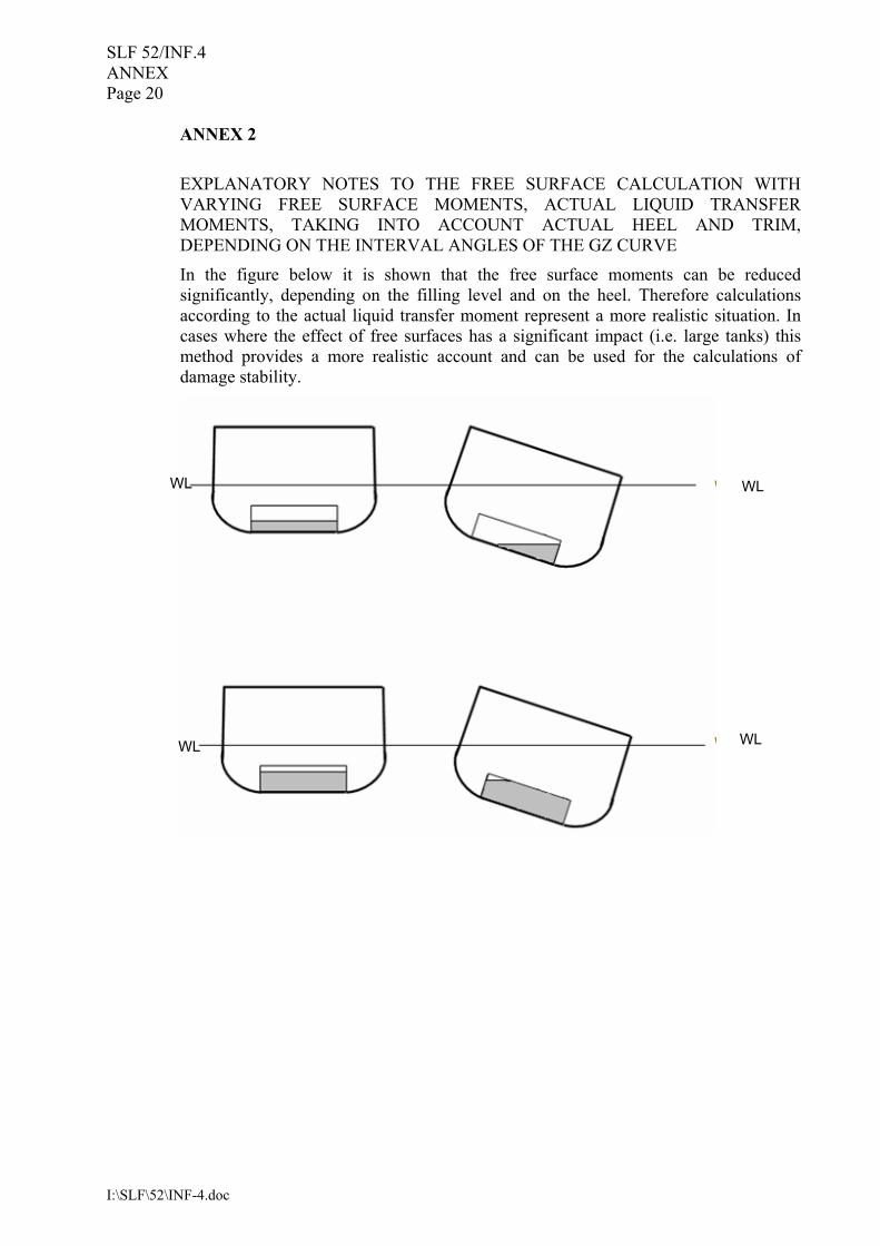
ANNEX 2 EXPLANATORY NOTES TO THE FREE SURFACE CALCULATION WITH VARYING FREE SURFACE MOMENTS, ACTUAL LIQUID TRANSFER MOMENTS, TAKING INTO ACCOUNT ACTUAL HEEL AND TRIM, DEPENDING ON THE INTERVAL ANGLES OF THE GZ CURVE
In the figure below it is shown that the free surface moments can be reduced significantly, depending on the filling level and on the heel. Therefore calculations according to the actual liquid transfer moment represent a more realistic situation. In cases where the effect of free surfaces has a significant impact (i.e. large tanks) this method provides a more realistic account and can be used for the calculations of damage stability.
WL WL
WL WL
SLF 52/INF.4 ANNEX Page 21
I:\SLF\52\INF-4.doc
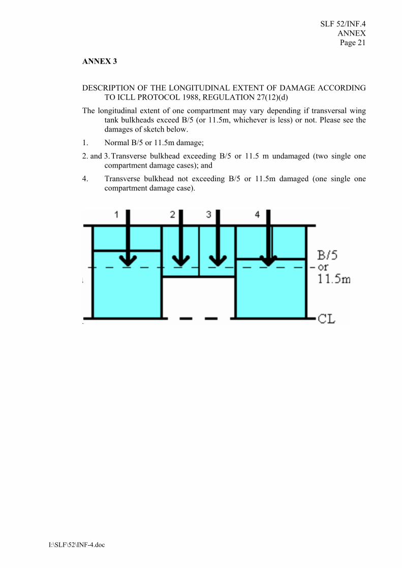
ANNEX 3
DESCRIPTION OF THE LONGITUDINAL EXTENT OF DAMAGE ACCORDING
TO ICLL PROTOCOL 1988, REGULATION 27(12)(d)
The longitudinal extent of one compartment may vary depending if transversal wing tank bulkheads exceed B/5 (or 11.5m, whichever is less) or not. Please see the damages of sketch below.
1. Normal B/5 or 11.5m damage;
2. and 3. Transverse bulkhead exceeding B/5 or 11.5 m undamaged (two single one compartment damage cases); and
4. Transverse bulkhead not exceeding B/5 or 11.5m damaged (one single one compartment damage case).
SLF 52/INF.4 ANNEX Page 22
I:\SLF\52\INF-4.doc
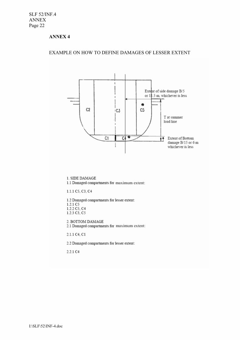
ANNEX 4
EXAMPLE ON HOW TO DEFINE DAMAGES OF LESSER EXTENT
SLF 52/INF.4 ANNEX Page 23
I:\SLF\52\INF-4.doc
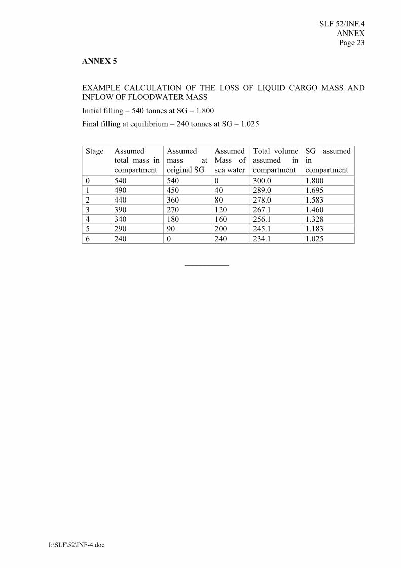
ANNEX 5
EXAMPLE CALCULATION OF THE LOSS OF LIQUID CARGO MASS AND INFLOW OF FLOODWATER MASS
Initial filling = 540 tonnes at SG = 1.800
Final filling at equilibrium = 240 tonnes at SG = 1.025
Stage Assumed total mass in compartment
Assumed mass at original SG
Assumed Mass of sea water
Total volume assumed in compartment
SG assumed in compartment
0 540 540 0 300.0 1.800 1 490 450 40 289.0 1.695 2 440 360 80 278.0 1.583 3 390 270 120 267.1 1.460 4 340 180 160 256.1 1.328 5 290 90 200 245.1 1.183 6 240 0 240 234.1 1.025
___________