guidelines for using building information modelling in general … · later and (ii) archicad...
TRANSCRIPT


GUIDELINES FOR USING BUILDING INFORMATION MODELLING IN GENERAL BUILDING PLANS SUBMISSION
Contents 1. Background .......................................................................................................................... 5
2. Objectives............................................................................................................................. 5
3. Scope .................................................................................................................................... 6
4. BIM File Submission Requirements
4.1 Introduction ................................................................................................................. 7
4.2 Performance Requirements........................................................................................ 7
4.3 Administrative Requirements ..................................................................................... 8
4.4 Level of Development.................................................................................................. 9
5. Specification for Native File
5.1 Technical Requirements............................................................................................ 10
5.1.1 Unit and Measurement.................................................................................. 10
5.1.2 Mathematical Modelling ................................................................................ 10
5.1.3 Spatial Location and Co-ordination ............................................................... 10
5.1.4 Colour Code System ....................................................................................... 11
5.1.5 3D Model......................................................................................................... 11
5.2 Essential Views for Composing the Prescribed Plans .............................................. 13
5.2.1 Essential Views................................................................................................ 13
5.2.2 Block / Key Plan............................................................................................... 14
5.2.3 Floor Plan ........................................................................................................ 15
5.2.4 Section and Elevation..................................................................................... 16
5.2.5 Details.............................................................................................................. 19
5.2.6 EVA Diagram ................................................................................................... 20
5.2.7 Open Space Diagram ...................................................................................... 22
5.2.8 Fire Compartment Diagram ........................................................................... 22
5.2.9 Site Area and SC Diagram............................................................................... 24
5.2.10 GFA Diagram................................................................................................... 25
5.2.11 UFA Diagram................................................................................................... 27
5.2.12 UFS Diagram ................................................................................................... 28
5.2.13 Assessment of Prescribed Windows ............................................................. 29
5.2.14 Diagrams Showing Compliance with the SBD Guidelines ............................ 30
5.3 Essential Schedules for Composing the Prescribed Plans ....................................... 32
5.3.1 List of Drawings .............................................................................................. 33
5.3.2 Site Area Calculation ...................................................................................... 34
5.3.3 List of Coordinates.......................................................................................... 34
1

35
40
45
50
55
60
GUIDELINES FOR USING BUILDING INFORMATION MODELLING IN GENERAL BUILDING PLANS SUBMISSION
5.3.4 Development Schedule ..................................................................................
5.3.5 Site Classification, Summary of SC and PR Calculation................................. 35
5.3.6 Open Space Calculation.................................................................................. 37
5.3.7 Computation for GFA Concession Requirements ......................................... 37
5.3.8 List of GFA Concessions.................................................................................. 37
5.3.9 List of Modifications ....................................................................................... 39
5.3.10 Schedule of Minimum Number and Width of Exit Doors and Exit Routes.
5.3.11 Schedule of Discharge Value ........................................................................ 41
5.3.12 Schedule of FRR / Compartment Schedule.................................................. 42
5.3.13 Schedule of Sanitary Fitment Provisions...................................................... 43
5.3.14 Window Area Calculation.............................................................................. 44
5.3.15 Refuse Storage and Material Recovery Chamber Calculation ....................
5.3.16 Floor Area Calculation for TBE Room ........................................................... 45
5.3.17 Lift Shaft Schedule......................................................................................... 46
5.4 Amendment Plans and Alterations & Additions Plans............................................. 47
5.4.1 Amendment Plans .......................................................................................... 47
5.4.2 A&A Plans........................................................................................................ 48
5.5 Other Essential Information on Prescribed Plans or BIM Files for BD .................... 49
5.5.1 Title Block........................................................................................................ 49
5.5.2 Legends, Abbreviations and Fire Services (FS) Notes ...................................
5.5.3 Development Information ............................................................................. 50
5.6 Other Information on Prescribed Plans or BIM Files for Other Departments........ 52
5.6.1 Planning Department ..................................................................................... 52
5.6.2 Lands Department.......................................................................................... 54
6. File Structure and File Naming Convention
6.1 File Size.......................................................................................................................
6.2 Linked Files................................................................................................................. 55
6.3 BIM File Reference..................................................................................................... 55
6.4 Drawing Naming ........................................................................................................ 57
7. Review..................................................................................................................... .................................................................................................................................. 59
Appendix 1: Legends .............................................................................................................
Appendix 2: Abbreviations ................................................................................................... 64
Appendix 3: FS Notes ............................................................................................................ 71
Appendix 4: Planning Department Building Plan Vetting Form ....................................... 75
2

GUIDELINES FOR USING BUILDING INFORMATION MODELLING IN GENERAL BUILDING PLANS SUBMISSION
List of Figures
Figure 1 Example of View for 3D Model ........................................................................12 Figure 2 Example of First-person View ..........................................................................12 Figure 3 Examples of View for Block/ Key Plan .............................................................14 Figure 4 Example of View for Floor Plan........................................................................15 Figure 5 Examples of View for Section...........................................................................17 Figure 6 Examples of View for Elevation .......................................................................18 Figure 7 Examples of View for Details............................................................................19 Figure 8 Examples of View for EVA ................................................................................21 Figure 9 Example of View for Open Space Diagram......................................................22 Figure 10 Examples of View for Fire Compartment Diagram.........................................23 Figure 11 Examples of View for SC Diagram....................................................................24 Figure 12 Examples of View for GFA Diagrams ...............................................................26 Figure 13 Examples of View for UFA Diagrams ...............................................................28 Figure 14 Example of View for Prescribed Window Provisions......................................29 Figure 15 Example of View for Building Setback Diagram under SBD Guidelines.........30 Figure 16 Example of View for Building Separation Diagram under SBD Guidelines....31 Figure 17 Examples of Essential Schedules for Composing the Prescribed Plans .........32 Figure 18 Examples of Drawing List .................................................................................33 Figure 19 Example of Site Area Calculation.....................................................................34 Figure 20 Examples of List of Coordinates ......................................................................34 Figure 21 Example of Development Schedule.................................................................35 Figure 22 Examples of SC and PR Calculation..................................................................36 Figure 23 Example of Open Space Calculation................................................................37 Figure 24 Examples of the Lists of GFA Concession Items and Areas ............................38 Figure 25 Example of List of Modifications .....................................................................39 Figure 26 Examples of Schedule of Minimum Number and Width of Exit Doors and
Exit Routes on each floor................................................................................40 Figure 27 Example of Schedule of Discharge Value ........................................................41 Figure 28 Example of Schedule of FRR for Elements of Construction ...........................42 Figure 29 Example of Schedule of Sanitary Fitment Provisions .....................................43 Figure 30 Examples of Schedule of Window Area Calculation.......................................44 Figure 31 Example of Refuse Storage and Material Recovery Chamber Calculation....45 Figure 32 Example of Floor Area Calculation for TBE Room...........................................45 Figure 33 Example of Lift Shaft Schedule ........................................................................46 Figure 34 Example of Title Block ......................................................................................49 Figure 35 Example of Development Information............................................................51 Figure 36 Key Information in the Building Plan Vetting Form ........................................53 Figure 37 Example of Linked File Structure .....................................................................55 Figure 38 Example of Drawing Names in ArchiCAD ........................................................59 Figure 39 Example of Drawing Names in Revit................................................................59
3

GUIDELINES FOR USING BUILDING INFORMATION MODELLING IN GENERAL BUILDING PLANS SUBMISSION
List of Table
Table 1 Colour Code System for GFA diagrams .............................................................25
Table 2 Description of Fields for BIM File Reference.....................................................56
Table 3 Blank Form for BIM File Reference ....................................................................56
Table 4 Examples for BIM File Reference .......................................................................56
Table 5 Blank Form for Drawing Naming........................................................................57
Table 6 Code for Type of Drawing...................................................................................57
Table 7 Code for Drawing Number .................................................................................57
Table 8 Reference of Drawing Title in PNAP ADV-33.....................................................58
Table 9 Examples of Drawing Names..............................................................................58
4

GUIDELINES FOR USING BUILDING INFORMATION MODELLING IN GENERAL BUILDING PLANS SUBMISSION
1. Background
Building Information Modelling (BIM) technology is identified as one of the key drivers to enhance the design, construction and project management in the construction industry. Buildings Department (BD) encourages Authorized Persons (APs), Registered Structural Engineers (RSEs) and Registered Geotechnical Engineers (RGEs) to consider adopting BIM in their building projects.
BD accepts the use of computer for calculating floor areas of buildings in the preparation of general building plans (GBP) submission. Practice Note for Authorized Persons, Registered Structural Engineers and Registered Geotechnical Engineers (PNAP) ADM-19 sets out the rules and pre-requisites regarding such computer use. If BIM technology is used in the preparation of GBP, this Guidelines for Using Building Information Modelling in General Building Plans submission (the Guidelines) should be followed.
2. Objectives
The Guidelines aim to set out:
(a) General guidelines to facilitate APs in preparing GBP by BIM authoring software; and
(b) Recommended good practices for the enhancement of submission standard.
While non-conformity with the Guidelines will not constitute a ground for disapproval of the plans, the Building Authority (BA) may not accept the BIM GBP electronic files for the mathematical calculation of areas depending on the degree of non-conformity.
5

GUIDELINES FOR USING BUILDING INFORMATION MODELLING IN GENERAL BUILDING PLANS SUBMISSION
3. Scope
The Guidelines cover the following:
(a) BIM file submission requirements (b) Specification for native file
o Technical requirements o Essential views for composing the prescribed plans o Essential schedules for composing the prescribed plans o Amendment Plans and Alterations & Additions Plans o Other essential information on prescribed plans or BIM files
for BD o Other information on prescribed plans or BIM files for other
departments (c) File structure and file naming convention
6

GUIDELINES FOR USING BUILDING INFORMATION MODELLING IN GENERAL BUILDING PLANS SUBMISSION
4. BIM File Submission Requirements
4.1 Introduction
This chapter describes the requirements on BIM GBP electronic files (BIM files) accompanying the submission of the prescribed GBP plans to the BA for the purposes of PNAP ADM-19.
4.2 Performance Requirements
(a) All BIM files shall meet the following requirements: (i) BO and all allied regulations; (ii) Relevant codes of practice, PNAPs and circular letters issued by the
BA; and (iii) Relevant BIM sample templates (Revit or ArchiCAD) prepared by the
BA. (b) Information contained in BIM files shall be identical to the information
shown on the prescribed GBP plans. Prescribed plans submitted to the BA should be directly generated from the corresponding BIM model.
(c) The Colour Code System as specified in Section 5.1.4 of the Guidelines for various building components and area diagrams shall be adopted.
(d) Area diagrams should be shown with the corresponding halftone under laying floor plans for ease of verification.
(e) All linear dimensions and area diagrams of the BIM file should be fit for verification to the extent that the accuracy of area calculations can be checked and mathematical errors, if any, can be identified.
(f) The computation of all area diagrams on prescribed plans should be verifiable with the BIM software, both by selecting a pre-set zone / area and by specifying points to define what to measure.
(g) All irrelevant data for statutory submission, such as lighting, reflected ceiling plan, building services provisions and the like shall be removed from the BIM file.
7

GUIDELINES FOR USING BUILDING INFORMATION MODELLING IN GENERAL BUILDING PLANS SUBMISSION
4.3 Administrative Requirements
(a) The BIM files should be stored in a non-rewritable DVD-ROM in ISO/IEC 13346:1995 format (i.e. DVD format). Except otherwise agreed by the BA, all other electronic submission media are not acceptable.
(b) Each BIM file should be limited to the size of 500MB. Each BIM file should contain 3D model, views, schedules, as well as the pre-set drawing sheets including plans, area diagrams, calculations, etc. for the production of the hardcopy of prescribed plans. The text file should be included in the DVD-ROM to describe the linked files’ hierarchy structure.
(c) BA currently accepts BIM native files created by (i) Revit version 2017 or later and (ii) ArchiCAD version 21 or later only. As BIM technology is fast developing, there may be add-ons assistant programs or in-house scripts used for enhancing automation in the BIM file production. Add-ons or other implanted automation may cause the submitted BIM file not usable by BD’s standard Revit or ArchiCAD software. It is the APs’ responsibility to ensure that the purposes of the BIM model are served, as elaborated in the Guidelines, without relying on add-ons or additional scripts.
(d) The use of software, other than Revit and ArchiCAD, requires prior acceptance from the BA. As a general rule for such prior acceptance, the APs should submit at least one test sample together with the enabling software to the BA for installation and testing. For the avoidance of doubt, BA does not accept any web based BIM software.
(e) Revit files should be saved in “.rvt” format and ArchiCAD files in “.pla” format only. All other lightweight, compressed or zipped file formats such as “.dwf”, “.dwfx” and “.bimx” will not be accepted.
(f) Drawing title blocks with drawing number, revision number, legends, site / project title, drawing title, etc. as detailed in Section 5.4.1 should be inserted in every drawing for identification purpose.
(g) BIM files submitted in DVD ROM format should be self-contained and detached from the originating server. It shall be able to be opened on any standalone computer with the abovementioned software. All “X-Ref” files for the BIM model such as xlsx and pdf files should be stored in respective sub-folders in DVD ROM, and the link between all “X-Ref” files and BIM main file should be appropriately connected.
8

GUIDELINES FOR USING BUILDING INFORMATION MODELLING IN GENERAL BUILDING PLANS SUBMISSION
4.4 Level of Development
BIM technology enables the BIM model to contain geometrical and non-geometrical information as BIM elements. Geometrical information includes size, volume, location, orientation, etc. while non-geometrical information includes specifications, performance data, cost, etc.
BD notices various international organisations attempting to standardise BIM elements. One of the popular standards is the “Level of Development” (LOD), according to the American Institute of Architect. The LOD is classified into six categories namely LOD 100, LOD 200, LOD 300, LOD 350, LOD 400 and LOD 500. Reference on the LOD classification and specification may refer to https://bimforum.org/ . As a general principle, APs are advised to adopt LOD 300 in the preparation of BIM files though on some occasions APs may adopt LOD below 300 (e.g. indication of E/M plants, exhausted ducts) or LOD above 300 (e.g. special design details).
9

GUIDELINES FOR USING BUILDING INFORMATION MODELLING IN GENERAL BUILDING PLANS SUBMISSION
5. Specification for Native File
The native file should contain the building proposal model and complete with all views, schedules, calculations and annotations essential for the production of the prescribed plans. All BIM submissions should adopt a unified modelling methodology, and the native file should be created in a standardised file structure.
5.1 Technical Requirements
5.1.1 Unit and Measurement
The model should use consistent unit and measurement across the project with default drawing units in millimetres (mm) with a precision rounded up to the nearest mm unit.
All floor areas and volumes should be presented in square metres (m2) and cubic metres (m3) respectively and rounded off to three decimal places.
All site areas should be rounded off to the nearest 0.1m2 for site area less than 2,000m2 and to the nearest 1m2 for site area of 2,000m2 or above in accordance with PNAP ADM-21.
5.1.2 Mathematical Modelling
All dimensions should be true dimensions generated automatically by the software. Numerical dimensions inputted manually in the BIM file are not acceptable.
5.1.3 Spatial Location and Co-ordination
The BIM origin point and orientation of the model should be based on the actual location of the development by referring two widely used Hong Kong geodetic horizontal and vertical control networks, namely the Hong Kong 1980 Grid System (HK 1980 Grid) and Hong Kong Principal Datum (HKPD).
The HK 1980 Grid and HKPD should be presented in metres corrected to three decimal places (i.e. (8XX,XXX.XXX mN, 8XX,XXX.XXX mE) and (X.XXX mPD). Negative sign should be added for negative mPD (i.e. – X.XXX mPD).
10

GUIDELINES FOR USING BUILDING INFORMATION MODELLING IN GENERAL BUILDING PLANS SUBMISSION
5.1.4 Colour Code System
This paragraph aims to introduce two colour code systems.
(a) Building material and description on floor plans
PNAP ADM-9 specifies that every plan submitted for approval should be coloured to differentiate existing works from proposed new works. The preferred colour code as shown in Appendix A of PNAP ADM-9 should be adopted.
(b) Gross Floor Area (GFA) diagrams
The preferred GFA colour code as described in Section 5.2.10 of the Guidelines should be adopted.
5.1.5 3D Model
The BIM files should contain a 3D computer model representing the proposal on the site with its immediate surroundings. The model includes data of building components externally and internally, such as internal partition walls, internal staircases, building façades, windows, projections, architectural features, etc.
The 3D model should be able to be rotated in all directions for checking, viewing, zooming in/out, etc. by utilizing the functions of BIM software to facilitate inspection of building components and virtual walk-through of the building model in the first-person view.
11

GUIDELINES FOR USING BUILDING INFORMATION MODELLING IN GENERAL BUILDING PLANS SUBMISSION
Figure 1 Example of View for 3D Model
Figure 2 Example of First-person View
12

GUIDELINES FOR USING BUILDING INFORMATION MODELLING IN GENERAL BUILDING PLANS SUBMISSION
5.2 Essential Views for Composing the Prescribed Plans
APs are recommended to set up the following views with sufficient information to demonstrate compliance with the BO and its regulations, relevant codes of practices, PNAPs and circular letters issued by the BA. For the verification of areas and dimensions as proposed in the prescribed plans using the submitted BIM file, the following views shall be included in the file composition.
5.2.1 Essential Views
The BIM file should contain the following views, if applicable, but not limited to:
(a) Block/ Key plan (b) Floor plans (c) Sections (d) Elevations (e) Typical details (f) Emergency vehicular access (EVA) diagrams (g) Open space diagrams (h) Fire compartment diagrams (i) Site area and site coverage (SC) diagrams (j) GFA diagrams (k) Usable floor area (UFA) diagrams (l) Usable floor space (UFS) diagrams (m) Assessment of prescribed windows (n) Diagrams showing compliance with the Sustainable Building Design
(SBD) Guidelines
13

GUIDELINES FOR USING BUILDING INFORMATION MODELLING IN GENERAL BUILDING PLANS SUBMISSION
5.2.2 Block / Key Plan
Block / Key plan scale not less than 1:500, should contain the following information, if applicable, but not limited to:
(a) Site boundary, (b) Site area coloured in pink (recommended RGB: 255,218,236), (c) Lot number, (d) Specified streets for site classification, (e) Boundary coordinates and dimensions (examples as illustrated in
Section 5.3.3), (f) Location of vehicular run-in/out, (g) The extent of special areas (e.g. Scheduled Area, non-building area,
green/yellow/brown/special areas under the lease), and (h) North direction symbol.
Figure 3 Examples of View for Block / Key Plan
14

GUIDELINES FOR USING BUILDING INFORMATION MODELLING IN GENERAL BUILDING PLANS SUBMISSION
5.2.3 Floor Plan
The floor plan should contain the following information, if applicable, but not limited to:
(a) Demonstration of compliance with the BO and its regulations as well as the prescriptive requirements stipulated in various codes of practices, PNAPs and circular letters,
(b) Grids and grid dimensions showing principal dimensions of the building, as well as the distance between structural columns,
(c) Elevation and section marks for the corresponding view, (d) Wall thickness, (e) Room/space usage/building line above/door marks, (f) Dimensions showing the size of rooms, the width of
corridors/staircases, etc., (g) Indication with dimensions of architectural features, projections,
cladding, curtain wall, if any, and (h) Colour code according to PNAP ADM-9.
Figure 4 Example of View for Floor Plan
15

GUIDELINES FOR USING BUILDING INFORMATION MODELLING IN GENERAL BUILDING PLANS SUBMISSION
5.2.4 Section and Elevation
Section and elevation should contain the following information, if applicable, but not limited to:
(a) Grids and grid dimensions showing principal dimensions of the building as appropriate,
(b) Floor to floor height regarding structural floor levels, (c) Each floor level in HKPD, (d) Indication with dimensions of architectural features, projections,
cladding and curtain wall, if any, (e) Street levels adjoining to corresponding section/ elevation, (f) Building height under the Building (Planning) Regulations (B(P)R) with
reference to mean street level, (g) Building height restriction limit (mPD) under statutory town plans and
government leases as stipulated in Joint Practice Note (JPN) No. 5, and (h) Colour code according to PNAP ADM-9.
16

GUIDELINES FOR USING BUILDING INFORMATION MODELLING IN GENERAL BUILDING PLANS SUBMISSION
Figure 5 Examples of View for Section
17

GUIDELINES FOR USING BUILDING INFORMATION MODELLING IN GENERAL BUILDING PLANS SUBMISSION
Figure 6 Examples of View for Elevation
18

GUIDELINES FOR USING BUILDING INFORMATION MODELLING IN GENERAL BUILDING PLANS SUBMISSION
5.2.5 Details
Details should contain the following information, if applicable, but not limited to:
(a) Sufficient labelling to identify the location of details, (b) Sufficient labelling to identify typical and non-typical details, and (c) Sufficient critical dimensions, levels and design of building components
in compliance with the BO and its regulations, relevant PNAPs and circular letters.
Typical examples for details required under various PNAPs include gas aperture, utility platform, balcony, A/C platform, curtain wall, non-structural prefabricated external wall, sunken slab, protective barrier, accessible toilet, tactile warning strips for escalators, projecting windows, acoustic windows, acoustic fins, vertical greening, cladding, vertical barrier at atrium, details of modular integrated construction, etc.
It is the common practice to use 2D details created by CAD, to complement the BIM model. CAD is also one of the acceptable computer softwares under Appendix F of PNAP ADM-19. BD is ready to accept the details produced by CAD or BIM provided that APs have clearly indicated the software in their GBP electronic files.
Figure 7 Example of View for Details
19

GUIDELINES FOR USING BUILDING INFORMATION MODELLING IN GENERAL BUILDING PLANS SUBMISSION
5.2.6 EVA Diagram
EVA Diagram should contain the following information, if applicable, but not limited to:
(a) Demonstration of compliance with the Regulation 41D of the B(P)R, Part D of Code of Practice for Fire Safety in Buildings 2011 (FS Code) and PNAP APP-136 (such as calculation of the total perimeter of the building and length of major façade),
(b) Principal dimensions showing the building perimeter and façade served by EVA as appropriate,
(c) Demarcation of the EVA and the major façade, and (d) Corresponding schedule and calculation.
20

GUIDELINES FOR USING BUILDING INFORMATION MODELLING IN GENERAL BUILDING PLANS SUBMISSION
Figure 8 Examples of View for EVA
21

GUIDELINES FOR USING BUILDING INFORMATION MODELLING IN GENERAL BUILDING PLANS SUBMISSION
5.2.7 Open Space Diagram
Open Space Diagram should contain the following information, if applicable, but not limited to:
(a) The location and dimensions of open space with reference to the site classification, and
(b) Corresponding schedule and calculation.
Figure 9 Example of View for Open Space Diagram
5.2.8 Fire Compartment Diagram
Fire Compartment Diagram should contain the following information, if applicable, but not limited to:
(a) Grids and grid dimensions as appropriate, (b) Essential dimensions and sufficient labelling to demarcate
compartments, (c) Delineation of various compartments preferably with different colour, (d) Indication of compartments diagram with the corresponding halftone
under laying floor plans as appropriate, and (e) Corresponding schedule and calculation.
22

GUIDELINES FOR USING BUILDING INFORMATION MODELLING IN GENERAL BUILDING PLANS SUBMISSION
Figure 10 Examples of View for Fire Compartment Diagram
23

GUIDELINES FOR USING BUILDING INFORMATION MODELLING IN GENERAL BUILDING PLANS SUBMISSION
5.2.9 Site Area and SC Diagram
Site area and SC diagram should contain the following information, if applicable, but not limited to:
(a) Site boundary lines and dimensions as appropriate, (b) Outlines of the roof covered area highlighting in colour or with explicit
annotation and dimensions as appropriate, (c) Sufficient labelling on different buildings with their corresponding roof
covered area, and (d) Corresponding schedule and calculation.
Figure 11 Examples of View for SC Diagram
24

GUIDELINES FOR USING BUILDING INFORMATION MODELLING IN GENERAL BUILDING PLANS SUBMISSION
5.2.10 GFA Diagram
GFA diagram should contain the following information, if applicable, but not limited to:
(a) Grids and grid dimensions as appropriate, (b) Essential dimensions for layout design, (c) Adoption of colour code system as listed in Table 1 below, (d) Indication of GFA diagram with the corresponding halftone under
laying floor plans, (e) Pre-set GFA zones / areas should be labelled appropriately and easily
cross-referenced between the GFA diagrams and the corresponding schedule and calculation, and
(f) Corresponding schedule and calculation.
Categories of GFA Pre-defined Colour
RGB Colour System1
1. Accountable domestic GFA ORANGE 255, 164 ,25
2. Accountable non-domestic GFA2 RED 227, 100, 102
3. Disregarded GFA NOT subject to the overall 10% cap
a) Concession items specified in PNAP APP-151 (other than carpark, loading and unloading areas)
PURPLE 191, 000, 255
b) Carpark, loading and unloading areas and others
WOOD 222, 184, 135
4. Disregarded GFA subject to the overall 10% cap
a) Concession items specified in PNAP APP-151
DEEP BLUE 30, 144, 255
b) Others LIGHT BLUE 144, 214, 236
Table 1 Colour Code System for GFA diagrams
1 Colours are constructed from the combination of red, green and blue colours. 2 BA may treat a hotel development as a non-domestic building for the purpose of GFA calculation
subject to the requirements as stipulated in PNAP APP-40. 25

GUIDELINES FOR USING BUILDING INFORMATION MODELLING IN GENERAL BUILDING PLANS SUBMISSION
Figure 12 Examples of View for GFA Diagrams
26

GUIDELINES FOR USING BUILDING INFORMATION MODELLING IN GENERAL BUILDING PLANS SUBMISSION
5.2.11 UFA Diagram
UFA diagram should contain the following information, if applicable, but not limited to:
(a) Grids and grid dimensions as appropriate, (b) Delineation of the aggregate UFA areas, either by colour or annotation,
and (c) Corresponding schedule and calculation.
27

GUIDELINES FOR USING BUILDING INFORMATION MODELLING IN GENERAL BUILDING PLANS SUBMISSION
Figure 13 Examples of View for UFA Diagrams
5.2.12 UFS Diagram
UFS diagram should contain the following information, if applicable, but not limited to:
(a) Grids and grid dimensions as appropriate, and (b) Delineation of the aggregate UFS areas, either by colour or annotation.
28

GUIDELINES FOR USING BUILDING INFORMATION MODELLING IN GENERAL BUILDING PLANS SUBMISSION
5.2.13 Assessment of Prescribed Windows
Prescribed window area diagram should contain the following information, if applicable, but not limited to:
(a) Prescribed window areas, (b) Rectangular horizontal plan in critical locations, (c) Openable windows either shown on floor plans or elevations, (d) Provision of windows for habitable rooms, kitchens and offices, (e) Disposition of windows, (f) In case of using a performance-based approach, diagrams showing
unobstructed vision area as defined under PNAP APP-130, and (g) Corresponding schedule and calculation.
Figure 14 Example of View for Prescribed Window Provisions
29

GUIDELINES FOR USING BUILDING INFORMATION MODELLING IN GENERAL BUILDING PLANS SUBMISSION
5.2.14 Diagrams Showing Compliance with the SBD Guidelines
The diagrams should contain the following information, if applicable, but not limited to:
(a) Demonstration of compliance with building separation, building setback and provision of site coverage of greenery according to PNAP APP-152, and
(b) Site coverage of greenery areas should be identifiable to the extent that BD can differentiate the distribution of uncovered greenery areas and green features such as water features in primary and non-primary zone according to PNAP APP-152.
Figure 15 Example of View for Building Setback Diagram under SBD Guidelines
30

GUIDELINES FOR USING BUILDING INFORMATION MODELLING IN GENERAL BUILDING PLANS SUBMISSION
Figure 16 Example of View for Building Separation Diagram under SBD Guidelines
31

GUIDELINES FOR USING BUILDING INFORMATION MODELLING IN GENERAL BUILDING PLANS SUBMISSION
5.3 Essential Schedules for Composing the Prescribed Plans
Apart from various views generated from the model, the following schedules or tables should be included in the BIM file for demonstrating the statutory compliance:
(a) List of drawings, (b) Site area calculation, (c) List of coordinates, (d) Development Schedule, (e) Site classification, a summary of SC and Plot Ratio (PR), (f) Open space calculation, (g) Computation for GFA concession requirements, (h) List of GFA concessions, (i) List of modifications, (j) Schedule of minimum number and width of exit doors and exit routes, (k) Schedule of discharge value, (l) Schedule of fire resistance rating (FRR) / Compartment schedule, (m) Window area calculation, (n) Schedule of sanitary fitment provisions, (o) Refuse storage and material recovery chamber calculation, (p) Floor area calculation for Telecommunications and Broadcasting (TBE)
Room, and (q) Lift shaft concession calculation.
Figure 17 Examples of Essential Schedules for Composing the Prescribed Plans
32

GUIDELINES FOR USING BUILDING INFORMATION MODELLING IN GENERAL BUILDING PLANS SUBMISSION
5.3.1 List of Drawings
A list of drawings should be provided.
Figure 18 Examples of Drawing List
33

GUIDELINES FOR USING BUILDING INFORMATION MODELLING IN GENERAL BUILDING PLANS SUBMISSION
5.3.2 Site Area Calculation
All site areas should be rounded off to the nearest 0.1m2 for site area less than 2,000m2 and to the nearest 1m2 for site area of 2,000m2 or above in accordance with PNAP ADM-21.
Site Area Calculations: IL XXX S.A 2XXX.X mIL XXX S.B 2XXX.X mIL XXX S.C 2XXX.X m
Total : 2X,XXX.X m
Figure 19 Example of Site Area Calculation
5.3.3 List of Coordinates
A list of coordinates with bearings and distances should be provided as appropriate. Distances and coordinates should be provided to the nearest 0.001 of a metre without rounding off the figures. Bearings should be provided in the format of degrees-minutes-seconds (dd° mm' ss'') to the nearest 1 second without rounding off the figures.
BOUNDARY COORDINATES Hong Kong 1980 Grid Coordinates
POINT E (m) N (m) A 8xxxxx.xxx 8xxxxx.xxx B 8xxxxx.xxx 8xxxxx.xxx C 8xxxxx.xxx 8xxxxx.xxx D 8xxxxx.xxx 8xxxxx.xxx
BOUNDARY COORDINATES & DIMENSIONS: LOT NO. : IL XXX S.A POINT DISTANCE BEARING NORTH (m) EAST (m) A xxx.xxx dd° mm' ss'' 8xxxxx.xxx 8xxxxx.xxx B xxx.xxx dd° mm' ss'' 8xxxxx.xxx 8xxxxx.xxx Q xxx.xxx dd° mm' ss'' 8xxxxx.xxx 8xxxxx.xxx C xxx.xxx dd° mm' ss'' 8xxxxx.xxx 8xxxxx.xxx D xxx.xxx dd° mm' ss'' 8xxxxx.xxx 8xxxxx.xxx E xxx.xxx dd° mm' ss'' 8xxxxx.xxx 8xxxxx.xxx P xxx.xxx dd° mm' ss'' 8xxxxx.xxx 8xxxxx.xxx F xxx.xxx dd° mm' ss'' 8xxxxx.xxx 8xxxxx.xxx CURVE DATA: SDE ARC LENGTH (m) RADIUS (m) ANGLE CD xxx.xxx xxx.xxx dd° mm' ss'' DE xxx.xxx xxx.xxx dd° mm' ss'' FA xxx.xxx xxx.xxx dd° mm' ss''
Figure 20 Examples of List of Coordinates
34

GUIDELINES FOR USING BUILDING INFORMATION MODELLING IN GENERAL BUILDING PLANS SUBMISSION
5.3.4 Development Schedule
Development schedule should be provided.
Figure 21 Example of Development Schedule
5.3.5 Site Classification, Summary of SC and PR Calculation
Demonstration of compliance with the following should be provided:
(a) Regulations 18A, 19, 20, 21 and 23 of the B(P)R, such as information in supporting the proposed site classification, site area and PR, and
(b) Calculation of permitted PR by residual method under Regulation 21(2) of the B(P)R for composite building, if applicable.
35

GUIDELINES FOR USING BUILDING INFORMATION MODELLING IN GENERAL BUILDING PLANS SUBMISSION
Figure 22 Examples of SC and PR Calculation
36

GUIDELINES FOR USING BUILDING INFORMATION MODELLING IN GENERAL BUILDING PLANS SUBMISSION
5.3.6 Open Space Calculation
(a) Open space diagram and its disposition. (b) Calculation of required / provided open space.
OPEN SPACE REQUIRED : (CALCULATION REFER DWG. NO. C056 )
1 / 4 OF DOMESTIC ROOF OVER AREA = 511.531 s.m. x 0.250
= 127.883 s.m. 127.883
= 715.319 s.m. > s.m.
Figure 23 Example of Open Space Calculation
5.3.7 Computation for GFA Concession Requirements
(a) Pre-requisites under PNAP APP-151 and 152, if applicable, should be provided.
5.3.8 List of GFA Concessions
(a) Table showing all GFA concession items under Appendix A of PNAP APP-151 and Appendices G and H of PNAP ADM-2 should be provided, and
(b) Exempted GFA without ceiling cap and GFA subject to 10% cap under PNAP APP-151 should be provided.
37

GUIDELINES FOR USING BUILDING INFORMATION MODELLING IN GENERAL BUILDING PLANS SUBMISSION
Figure 24 Examples of the Lists of GFA Concession Items and Areas
38

GUIDELINES FOR USING BUILDING INFORMATION MODELLING IN GENERAL BUILDING PLANS SUBMISSION
5.3.9 List of Modifications
List of modifications as stated in Appendix A3 of PNAP ADV-33 should be provided.
Figure 25 Example of List of Modifications
39

GUIDELINES FOR USING BUILDING INFORMATION MODELLING IN GENERAL BUILDING PLANS SUBMISSION
5.3.10 Schedule of Minimum Number and Width of Exit Doors and Exit Routes
(a) Demonstration of compliance with Regulation 41(1) of B(P)R in the context of Clause B8.1 of FS Code, and
(b) Use, occupancy factor, the required / provided number and width of the exit doors and exit routes should be provided.
Figure 26 Examples of Schedule of Minimum Number and Width of Exit Doors
and Exit Routes on Each Floor
40

GUIDELINES FOR USING BUILDING INFORMATION MODELLING IN GENERAL BUILDING PLANS SUBMISSION
5.3.11 Schedule of Discharge Value
(a) Demonstration of compliance with Regulation 41(1) of B(P)R in the context of Clause B12 of FS Code, and
(b) The capacity of storeys served by stair, number of storeys, width and number of stairs provided, discharge value, etc. should be provided.
Figure 27 Example of Schedule of Discharge Value
41

GUIDELINES FOR USING BUILDING INFORMATION MODELLING IN GENERAL BUILDING PLANS SUBMISSION
5.3.12 Schedule of FRR / Compartment Schedule
(a) Demonstration of compliance with Regulation 90 of the Building (Construction) Regulations and Part C of the FS Code such as fire compartment area / volume calculations, and
(b) Use, compartment area / volume, FRR required, minimum dimensions of elements of construction, etc. should be provided.
Figure 28 Example of Schedule of FRR for Elements of Construction
42

GUIDELINES FOR USING BUILDING INFORMATION MODELLING IN GENERAL BUILDING PLANS SUBMISSION
5.3.13 Schedule of Sanitary Fitment Provisions
(a) Demonstration of compliance with Part II of the Building (Standards of Sanitary Fitments, Plumbing, Drainage Works and Latrines) Regulations,
(b) The location, associated use, total UFA and capacity per floor, (c) The number of persons with gender, and (d) Required / provided sanitary fitments.
Figure 29 Example of Schedule of Sanitary Fitment Provisions
43

GUIDELINES FOR USING BUILDING INFORMATION MODELLING IN GENERAL BUILDING PLANS SUBMISSION
5.3.14 Window Area Calculation
(a) Required window area assessment under Regulations 30, 31 and 36 of the B(P)R,
(b) Provided window area calculation, and (c) Use, UFA, required / provided openable area, required / provided
window area should be provided.
Figure 30 Examples of Schedule of Window Area Calculation
44
GUIDELINES FOR USING BUILDING INFORMATION MODELLING IN GENERAL BUILDING PLANS SUBMISSION
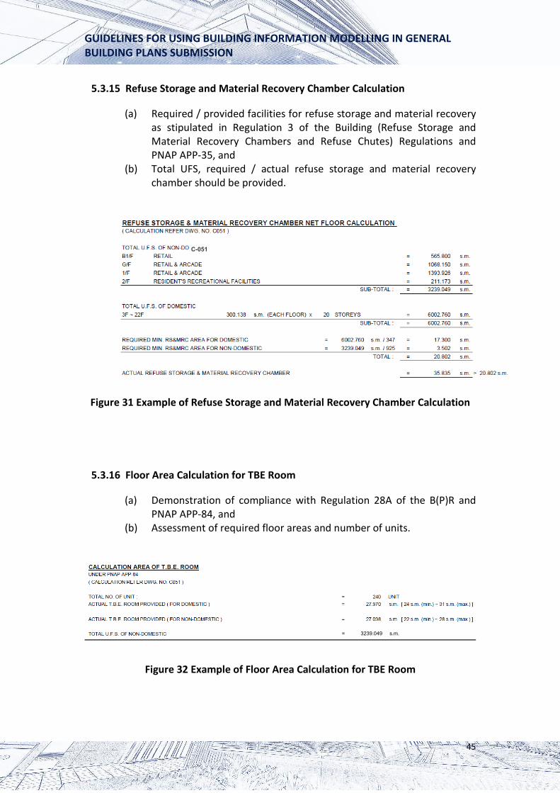
5.3.15 Refuse Storage and Material Recovery Chamber Calculation
(a) Required / provided facilities for refuse storage and material recovery as stipulated in Regulation 3 of the Building (Refuse Storage and Material Recovery Chambers and Refuse Chutes) Regulations and PNAP APP-35, and
(b) Total UFS, required / actual refuse storage and material recovery chamber should be provided.
C-051
Figure 31 Example of Refuse Storage and Material Recovery Chamber Calculation
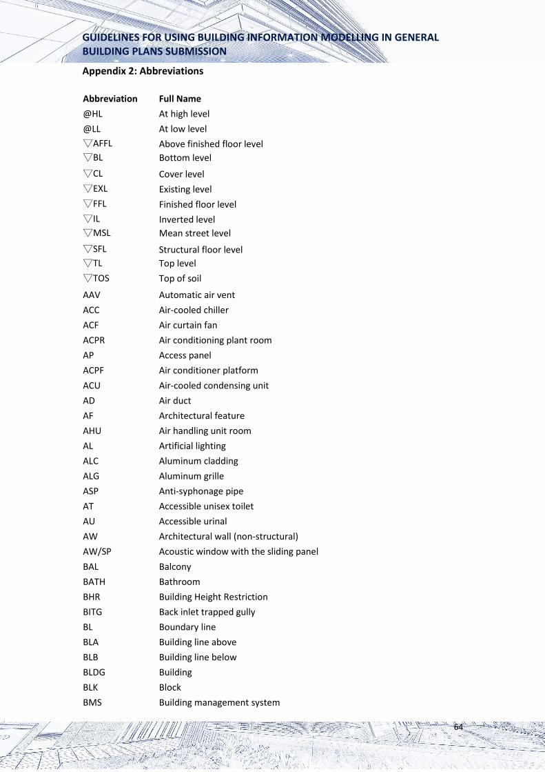
5.3.16 Floor Area Calculation for TBE Room
(a) Demonstration of compliance with Regulation 28A of the B(P)R and PNAP APP-84, and
(b) Assessment of required floor areas and number of units.
= 3239.049 s.m.
Figure 32 Example of Floor Area Calculation for TBE Room
45

GUIDELINES FOR USING BUILDING INFORMATION MODELLING IN GENERAL BUILDING PLANS SUBMISSION
5.3.17 Lift Shaft Schedule
(a) Lift shaft schedule for the purpose of GFA concessions under PNAP APP-89 should be provided.
LIFT SHAFT AREA
AREA NO. (S.M.) ①
STOREYS ②
TOTAL ③=① x ②
LT-1 LFS 4.725 2F~22F 21 99.23
LT-2 LFS 4.410 2F~22F 21 92.61
LT-3 LFS 4.410 GF~22F 23 101.43
13.545 293.265
Figure 33 Example of Lift Shaft Schedule
46

GUIDELINES FOR USING BUILDING INFORMATION MODELLING IN GENERAL BUILDING PLANS SUBMISSION
5.4 Amendment Plans and Alterations & Additions Plans
This chapter describes some modelling requirements, particularly to amendment plans and alterations & additions (A&A) plans.
5.4.1 Amendment Plans
After the approval of the first set of plans, either general building plans (GBP) to a new building or A&A plans to an existing building, it is not uncommon that APs would revise their design and submit amendment plans afterwards. To process the amendment plans using BIM software, the following practices should be adopted:
(a) The portion of floor layouts, sections, elevations with amendments should be shown, either by colouring or highlighting with annotation for easy identification. The remaining areas without amendments should be shown in black colour (recommended RGB: 0,0,0) and white colour (recommended RGB: 255,255,255).
(b) Revised figures in schedules / tables arising from amendments should be indicated in red colour or the revised figures with red underlines (recommended RGB: 204,0,51). Other figures without revision should be shown in black colour (recommended RGB: 0,0,0).
(c) In case a new schedule / table is added in the amendment plans, the new schedule / table should be enclosed by a red closed-loop (recommended RGB: 204,0,51).
(d) In general, deletion of approved works in the amendment plans should be shown in blue dotted lines (recommended RGB: 0,63,255). However, APs on some occasions may opt not to follow this practice where revision involves multiple blue dotted lines in the same locality and thus cause confusion to the readers.
(e) Section 5.2.10 introduces the new colour code system for GFA diagram. It creates unnecessary workload to the APs if BA requests the coloured GFA diagram in the amendment plans reflecting the revision only. Under such circumstances, BA accepts the full-colour GFA diagram in the amendments plans. APs are required to revise GFA figures in the schedule/table according to section 5.4.1(b) and 5.4.1(c) above.
(f) The above practices are applied to 2D view only. Application of the practices in the 3D model is not necessary at this stage.
47

GUIDELINES FOR USING BUILDING INFORMATION MODELLING IN GENERAL BUILDING PLANS SUBMISSION
5.4.2 A & A Plans
In preparing the A&A plans to an existing building, it is not uncommon the original approved plans of the existing building is drawn by the AutoCAD or Microstation software. It may not be viable to build up a 3D model by BIM for the whole building if the proposed A&A works are minor or localised. To process the A&A plans using BIM software, the following practices should be adopted:
(a) Building up a BIM model solely for A&A portion is generally sufficient. However, APs are encouraged to show the whole building in 3D graphics for extensive A&A works such as wholesale conversion of an industrial building.
(b) 2D plan views of the non-submission area should be inserted and shown on 2D sheet views with clear indication of the extent of A&A works.
(c) The floor layouts, sections, elevations with A&A works should be shown, either by colouring or highlighting with annotation for easy identification. The remaining areas without A&A works should be shown in black (recommended RGB: 0,0,0) and white colour (recommended RGB: 255,255,255).
(d) Revised figures in schedules / tables arising from A&A works should be indicated in red colour or the revised figures with red underlines (recommeded RGB: 204,0,51). Other figures without revision should be shown in black colour (recommended RGB: 0,0,0).
(e) In case a new schedule / table is added in the A&A plans, the new schedule / table should be enclosed by a red closed-loop (recommeded RGB: 204,0,51).
(f) In general, demolition of approved works in the A&A plans should be shown in blue dotted lines (recommended RGB: 0,63,255). APs on some occasions may opt not to follow this practice where revision involves multiple blue dotted lines in the same locality and thus cause confusion to the readers.
(g) In case A&A works involve revision in GFA, a full-colour GFA diagram as required under section 5.2.10 should be provided as far as possible. APs are also required to revise the GFA figures in the schedule / table according to section 5.4.1(d) and 5.4.1(e) above.
(h) The above practices are applied to 2D view only. Application of the practices in the 3D model is not necessary at this stage.
48

GUIDELINES FOR USING BUILDING INFORMATION MODELLING IN GENERAL BUILDING PLANS SUBMISSION
5.5 Other Essential Information on Prescribed Plans or BIM Files for BD
The information shown on electronic drawings output from the building model should be identical to the submitted prescribed plans. Acceptable standards as stipulated in PNAP ADV-33 are still applicable to BIM submission.
5.5.1 Title Block
When the model is output to 2D views, the views shall be identical to the submitted prescribed plans and contain the title block, as shown in Figure 34.
Figure 34 Example of Title Block
49

GUIDELINES FOR USING BUILDING INFORMATION MODELLING IN GENERAL BUILDING PLANS SUBMISSION
5.5.2 Legends, Abbreviations and Fire Services (FS) Notes
Legends, abbreviations and FS notes should be provided. See Appendices 1, 2 and 3 for details.
5.5.3 Development Information
Taking the advantages of BIM, it is highly recommended to provide useful development information in the BIM files upon completion of the project. The format of schedules is shown in Figure 35 below.
Legend: 1. File reference 2. Address 3. Lot number and description 4. Consent date 5. No. of the blocks, storeys, carpark and building type 6. No. of the domestic unit and unit size in usable floor area 7. Gross floor areas 8. Sub-total of the gross floor area of the residential housing unit 9. Usable floor areas
50

GUIDELINES FOR USING BUILDING INFORMATION MODELLING IN GENERAL BUILDING PLANS SUBMISSION
Are
aC
ode
1. F
ile R
efer
ence
Cons
ent d
ate
No.
of
Bloc
ks
No.
of
Stor
eys &
Carp
arks
Bu
ildin
g Ty
pe
Dom
estic
Uni
ts G
ross
Flo
or A
rea
Usa
ble
Floo
r Are
a 2.
Add
ress
3. L
ot n
o.N
o.
Unit
Size
D
omes
tic
Non
-dom
estic
D
omes
tic
Non
-do
mes
tic
4. T
.P.U
.
NTE
2/00
00/0
1 1
40
Apa
rtmen
t/Com
mer
cial
with
16
0 23
.2
0.0
0.0
0.0
0.0
4 42
resi
dent
's 12
3 30
.9
all o
ver 5
re
crea
tiona
l 20
5 31
.4
0.0
podi
um le
vels
fa
cilit
ies
443
39
46.1
69.0
(A
ddre
s)Ts
uen
Wan
Tow
n Lo
t No.
xxx
and
2
base
men
t lev
els
Lot n
o. (T
WTL
xxx)
62
4 cp
#REF
!
(Tot
al n
o. o
f RH
U) 63
349.
9
(RH
U)
0.0
(Oth
er)
3989
5.2
Com
mer
cial
1082
49.4
(Oth
er)
3706
3.0
(RH
U)
0.0
(Oth
er)
Unit size in terms of UFA
Figure 35 Example of Development Information
51

GUIDELINES FOR USING BUILDING INFORMATION MODELLING IN GENERAL BUILDING PLANS SUBMISSION
5.6 Other Information on Prescribed Plans or BIM Files for Other Departments
BD is the central clearing house to process all building plan submissions from the private sector through the Centralised Processing System. Upon receipt of plans, BD would disseminate them to relevant departments and organisations for processing. Taking advantage of BIM, APs are encouraged to incorporate other information as requested by other departments in the same BIM 3D model. The following paragraphs aim to facilitate APs in the preparation of BIM 3D model.
5.6.1 Planning Department
Statutory planning information such as permitted use and statutory zoning under the OZP / Development Permission Area Plan, relevant approved planning conditions, building intensity information, building height under OZP are recommended to be machine-readable for easy extraction. Planning Department has provided a checklist of Building Plan Vetting Form in Appendix 4 for reference. Figure 36 below lists out some key information which are mandatory requirements for the submission to the Planning Department.
52

GUIDELINES FOR USING BUILDING INFORMATION MODELLING IN GENERAL BUILDING PLANS SUBMISSION
Figure 36 Key Information in the Building Plan Vetting Form
53

GUIDELINES FOR USING BUILDING INFORMATION MODELLING IN GENERAL BUILDING PLANS SUBMISSION
5.6.2 Lands Department
To facilitate the processing of GBP under lease, APs should also observe Lands Department requirements such as submission of development schedule to indicate the extent of compliance with the lease conditions, separate calculation of GFA and SC as defined under the lease and specific requirement on use of computer for mathematical calculation of areas as stated in Practice Note Issue No. 3/2018 or any subsequent revision issued by the Lands Administration Office of the Lands Department.
54

GUIDELINES FOR USING BUILDING INFORMATION MODELLING IN GENERAL BUILDING PLANS SUBMISSION
6. File Structure and File Naming Convention
APs should follow the standardised file structure and file naming convention for BIM submission.
6.1 File Size
Native files are required for submission. It is important to control the file size. The non-essential and irrelevant data for statutory submission should be deleted, and the maximum file size for each native file is restricted to 500MB.
6.2 Linked Files
APs should adopt the following file structures for linked files in the form of external reference of objects/tables/schedules in native files, whichever is appropriate for the project. (a) Several BIM files are linked or connected to contain all information. It is
suitable for projects that comprise several buildings/towers or that with the large file size (e.g. a massive scale development with thousands of apartments).
(b) If several BIM files are adopted, Universal Naming Convention (UNC) paths or relative paths should be used for linking all BIM files. Relative locations should be used for defining the linking between BIM files.
(c) Subfolder layers should be used under the project folder, and the number of layers should be kept to a minimum as possible.
Project Folder Subfolder A
Subfolder 1
Subfolder 2
Subfolder B
Figure 37 Example of Linked File Structure
6.3 BIM File Reference
The BIM file reference should consist of 4 fields, as illustrated in Tables 2 to 4 below. The BIM file reference should be shown in the title block of each prescribed plan to identify the source file.
55

GUIDELINES FOR USING BUILDING INFORMATION MODELLING IN GENERAL BUILDING PLANS SUBMISSION
Field Description Maximum Digits BD File Reference1 File Reference number (including N/A
prefix and suffix) assigned by BD. Software Version2 Refers to the software version 4
which produces the native file Disc Submission No.3 Refers to the number of disc 2
submission Remarks User defined character (optional) 10
Notes: 1. The field should be blank for the first submission
2. "A21” refers to ArchiCAD 21, “R19” refers to Revit 2019. Total 4 digits cater for future use.
3. It refers to the actual number of disc submission and thus it is not necessarily equal to the number of plan submission.
Table 2 Description of Fields for BIM File Reference
BD File Reference Software Version
Disc Submission
No.
Remarks (User defined)
- - - - - -
Prefix Suffix
Table 3 Blank Form for BIM File Reference
Background of Submission Example of BIM File Reference
1. First GBP drawn by Revit 2019 R19-01
2. Subsequent amendment plan for Tower 2 2-9023-18-A21-05-Tower2 of a development under BD file reference 2/9023/18, drawn by ArchiCAD 21 (the 5th
submission of disc)
Table 4 Example for BIM File Reference
56

GUIDELINES FOR USING BUILDING INFORMATION MODELLING IN GENERAL BUILDING PLANS SUBMISSION
6.4 Drawing Naming
The drawing naming should consist of 3 fields, as shown in Table 5 below:
Drawing Number
Revision Number
Drawing Title
- -
Table 5 Blank Form for Drawing Naming
(a) Drawing Number The first field is the drawing number, which consists of 2 components, namely type of drawing and drawing number. The type of drawing is represented by a single digit, as illustrated in Table 6 below while the drawing number is represented by a 3-digit code, as illustrated in Table 7 below.
Code Type of Drawing A General Building Plan C Calculation/Schedule
Table 6 Code for Type of Drawing
Code Drawing Number 001 1st Drawing 002 2nd Drawing 999 999th Drawing
Table 7 Code for Drawing Number
(b) Revision Number The second field is the revision number, which is represented by a 2-digit code, as illustrated in alphabetical order. APs may omit some alphabets if they think fit (e.g. I, O) but the maximum number of characters shall not be more than 2 such as ‘A’, ‘B’, ‘C’, ‘Z’, ‘AA’, ‘AZ’ and ‘BA’.
(c) Drawing Title The third field is the drawing title for free-text input. APs may refer to PNAP ADV-33 as shown in Table 8 below.
57

GUIDELINES FOR USING BUILDING INFORMATION MODELLING IN GENERAL BUILDING PLANS SUBMISSION
Drawing Title SITE LOCATION PLAN AND NOTES BASEMENT FLOOR PLAN GROUND FLOOR PLAN SECTION A-A AND B-B ELEVATION PLAN SITE COVERAGE AND PLOT RATIO LIST OF GFA CONCESSIONS CALCULATION SITE LOCATION PLAN AND NOTES GFA DIAGRAM AND CALCULATION UFA DIAGRAM AND CALCULATION COMPARTMENT DIAGRAM EVA DIAGRAM AND CALCULATION CALCULATION SCHEDULES FOR MOE/ FRC/ SANITARY FITTINGS DRAINAGE PLAN SITE LOCATION PLAN AND NOTES
Table 8 Reference of Drawing Title in PNAP ADV-33
(d) Examples Examples of drawing names are illustrated in Table 9, Figures 38 and 39 below.
Examples Drawing Names 1. 2nd revision of ground floor plan in A004-B-GROUND FLOOR
the building plan, 4th drawing in the PLAN drawing list
2. 5th revision of Calculation/Schedule, 10th drawing in the drawing list -
C010-E-DLO.GFA
GFA calculation under the lease
Table 9 Examples of Drawing Names
58

GUIDELINES FOR USING BUILDING INFORMATION MODELLING IN GENERAL BUILDING PLANS SUBMISSION
Figure 38 Example of Drawing Names in ArchiCAD
Figure 39 Example of Drawing Names in Revit
7. Review
The Guidelines will be reviewed, taking into the experience gained. Suggestions to facilitate and improve the BIM submission are always welcome.
59

GUIDELINES FOR USING BUILDING INFORMATION MODELLING IN GENERAL BUILDING PLANS SUBMISSION
Appendix 1: Legends
AT
AU
MEAN STREET LEVEL
PROPOSED STRUCTURAL FLOOR LEVEL
PROPOSED FINISHED FLOOR LEVEL
MECHANICAL VENTILATION & ARTIFICIAL LIGHTING
MECHANICAL VENTILATION
ARTIFICIAL LIGHTING
ACCESSIBLE FACILITIES FOR PERSONS WITH A DISABILITY
FIREMAN’S LIFT
LEVEL DIFFERENCE
DROP KERB
OPENABLE WINDOW
IRRIGATION POINT
EV CHARGING STATION
EXIT SIGN AT HIGH LEVEL
NON-STRUCTURAL PRE-FABRICATED EXTERNAL WALL
HOSE REEL
FIRE SERVICE ACCESS POINT
ACCESSIBLE UNISEX TOILET
ACCESSIBLE URINAL
60

GUIDELINES FOR USING BUILDING INFORMATION MODELLING IN GENERAL BUILDING PLANS SUBMISSION
Doors
D1
D2
D3
D4
D5
D6
D7
D8
D9
D10
D11
D12
D13
D14
D15
D16
-/60/60 F.R.R. SELF-CLOSING DOOR
-/60/60 F.R.R. SELF-CLOSING DOOR WITH SMOKE SEAL
-/60/60 F.R.R. SELF-CLOSING DOOR WITH F.R.R. TRANSPARENT GLASS
UPPER PANEL
-/60/60 F.R.R. SELF-CLOSING DOOR WITH F.R.R. TRANSPARENT GLASS
UPPER PANEL AND SMOKE SEAL
-/120/120 F.R.R. SELF-CLOSING DOOR WITH F.R.R. TRANSPARENT GLASS
UPPER PANEL
-/120/120 F.R.R. SELF-CLOSING DOOR WITH F.R.R. TRANSPARENT GLASS
UPPER PANEL AND SMOKE SEAL
-/120/120 F.R.R. SELF-CLOSING DOOR
-/120/120 F.R.R. SELF-CLOSING DOOR WITH SMOKE SEAL
-/120/120 F.R.R. SELF-CLOSING LIFT SHAFT EMERGENCY ACCESS DOOR
WITH SMOKE SEAL
-/-/- F.R.R. SELF-CLOSING DOOR WITH SMOKE SEAL
-/-/- F.R.R. SELF-CLOSING DOOR WITH TRANSPARENT GLASS UPPER PANEL
AND SMOKE SEAL
-/-/- F.R.R. GLASS PANEL DOOR
-/60/60 F.R.R. GLASS PANEL DOOR
-/60/60 F.R.R. SELF-CLOSING DOOR WITH PANIC BOLT-ON INSIDE
-/-/- F.R.R. DOOR WITH PANIC BOLT-ON INSIDE
-/60/60 F.R.R. METAL DOOR
61

GUIDELINES FOR USING BUILDING INFORMATION MODELLING IN GENERAL BUILDING PLANS SUBMISSION
D17
D18
D19
D20
D21
D22
D23
D24
D25
D26
D27
D28
D29
D30
D31
D32
-/120/120 F.R.R. METAL DOOR
-/-/- F.R.R. DOOR
-/-/- F.R.R. DOOR FOR MAINTENANCE ONLY
-/120/- F.R.R. LIFT LANDING DOOR
-/60/- F.R.R. STEEL LOUVERS DOOR
-/120/120 F.R.R. ACCESS PANEL WITH SMOKE SEAL
-/30/30 F.R.R. SELF-CLOSING DOOR
-/30/30 F.R.R. SELF-CLOSING DOOR WITH SMOKE SEAL
-/30/30 F.R.R. SELF-CLOSING DOOR WITH F.R.R. TRANSPARENT GLASS
UPPER PANEL AND SMOKE SEAL
-/60/- F.R.R. SELF-CLOSING DOOR WITH F.R.R. TRANSPARENT GLASS UPPER
PANEL
-/120/- F.R.R. SELF-CLOSING DOOR WITH F.R.R. TRANSPARENT GLASS
UPPER PANEL
-/240/240 F.R.R. SELF-CLOSING DOOR
-/240/240 F.R.R. SELF-CLOSING DOOR WITH SMOKE SEAL
/240/240 F.R.R. SELF-CLOSING DOOR WITH F.R.R. TRANSPARENT GLASS
UPPER PANEL
-/240/240 F.R.R. SELF-CLOSING DOOR WITH F.R.R. TRANSPARENT GLASS
UPPER PANEL AND SMOKE SEAL
DOOR WITH FIXED LOUVRE PANEL WITH A MINIMUM SIZE OF 1/20 OF THE
FLOOR AREA OF THE ROOM
The door legends from D1 to D22 are extracted from PNAP ADV-33 with minor revision. D23 to D32 are newly added.
62

GUIDELINES FOR USING BUILDING INFORMATION MODELLING IN GENERAL BUILDING PLANS SUBMISSION
Fire Shutters
R1
R2
R3
R4
R5
-/120/- F.R.R. HORIZONTAL FIRE SHUTTER
-/120/- F.R.R. STEEL FIRE SHUTTER
-/60/60 F.R.R. STEEL FIRE SHUTTER
-/240/- F.R.R. STEEL FIRE SHUTTER
-/240/240 F.R.R. STEEL FIRE SHUTTER
The fire shutter legends from R1 to R5 are extracted from PNAP ADV-33 with minor revision.
Access Panels
AP1
AP2
AP3
AP4
-/60/60 F.R.R. SELF-CLOSING ACCESS PANEL
-/120/120 F.R.R. SELF-CLOSING ACCESS PANEL
-/240/240 F.R.R. SELF-CLOSING ACCESS PANEL
ACCESS PANEL
The access panel legends from AP1 to AP4 are newly added.
63
GUIDELINES FOR USING BUILDING INFORMATION MODELLING IN GENERAL BUILDING PLANS SUBMISSION
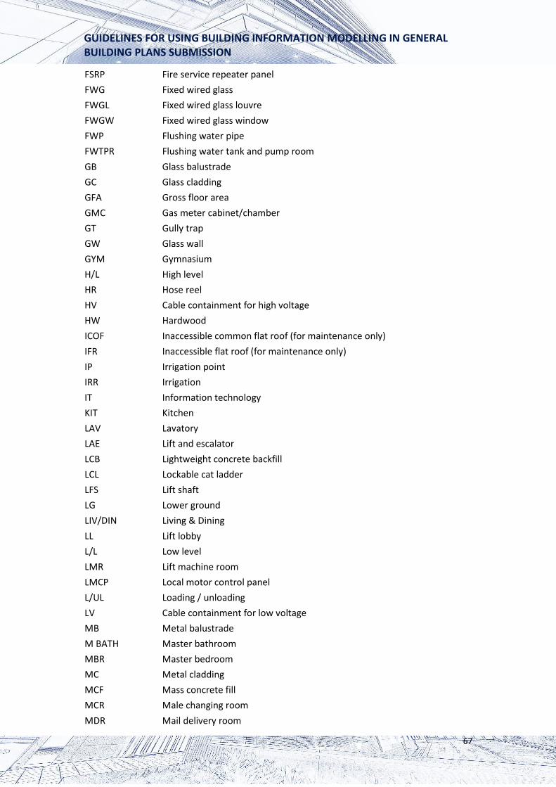
Appendix 2: Abbreviations
Abbreviation Full Name @HL At high level @LL At low level ▽AFFL Above finished floor level ▽BL Bottom level ▽CL Cover level ▽EXL Existing level ▽FFL Finished floor level ▽IL Inverted level ▽MSL Mean street level ▽SFL Structural floor level ▽TL Top level ▽TOS Top of soil
AAV Automatic air vent ACC Air-cooled chiller ACF Air curtain fan ACPR Air conditioning plant room AP Access panel ACPF Air conditioner platform ACU Air-cooled condensing unit AD Air duct AF Architectural feature AHU Air handling unit room AL Artificial lighting ALC Aluminum cladding ALG Aluminum grille ASP Anti-syphonage pipe AT Accessible unisex toilet AU Accessible urinal AW Architectural wall (non-structural) AW/SP Acoustic window with the sliding panel BAL Balcony BATH Bathroom BHR Building Height Restriction BITG Back inlet trapped gully BL Boundary line BLA Building line above BLB Building line below BLDG Building BLK Block BMS Building management system
64

GUIDELINES FOR USING BUILDING INFORMATION MODELLING IN GENERAL BUILDING PLANS SUBMISSION
BOH Back of house BR Bedroom BS British standard BSEN British standard European Norm BW Bay window CB Cantilevered beam CL Cat ladder CS Cantilevered slab CSB Cantilevered slab balcony CSC Cantilevered slab canopy C/C Centre to centre C/L Centre line CAP Capacity CC Covered channel
CD Cable duct CDP Condensation pipe CE Ceiling CI Cast iron CLA Covered landscape area CLD Cladding CMC Check meter cabinet COA Common area COF Common flat roof CORR Corridor CP Control panel CS Cantilevered slab CSB Cantilevered slab balcony CSC Covered surface channel CT Cable tray CTC Caretaker's counter CTQ Caretaker's quarter CW Curtain wall CWPR Cleansing water pump room D Duct DAS Davit arm system DG Dangerous goods store DI Drencher inlet DOM Domestic DP Down pipe DR Door DRE Drencher pipe DSP Drainage sump pump DT Disconnecting trap
65

GUIDELINES FOR USING BUILDING INFORMATION MODELLING IN GENERAL BUILDING PLANS SUBMISSION
DTD Deadend travel distance DWG Drawing E&M Electrical & mechanical EA Exhaust air EAD Exhaust air duct EAL Exhaust air louvre EDR Electric duct room EG Eaves gutter EMGR Emergency generator room ELR Electric room ELS Excavation and lateral support ELV Extra low voltage EMR Electric meter room EN European Norm ENT Entrance EQ Equal ESC Escalator EVA Emergency vehicular access EVC Electric vehicle charger EVCR Electric vehicle charger room FAI Fresh air inlet FB Fire blanket FBG Fibreglass FCC Fire control centre FCG Fixed clear glass FCU Fan coil unit FD Fire damper FDR Floor drain FE Fire extinguisher FLAV Female lavatory
FG Fixed glass FH Fire hydrant FHP Fire hydrant pipe FL Floor FLA Flue aperture FLL Fireman’s lift lobby FMCR Female changing room FPR Filtration plant room FR Flat roof FRS Firefighting & rescue stairway FS Fire services installation FSCR Fire service control room FSI Fire service inlet
66
GUIDELINES FOR USING BUILDING INFORMATION MODELLING IN GENERAL BUILDING PLANS SUBMISSION
FSRP Fire service repeater panel FWG Fixed wired glass FWGL Fixed wired glass louvre FWGW Fixed wired glass window FWP Flushing water pipe FWTPR Flushing water tank and pump room GB Glass balustrade GC Glass cladding GFA Gross floor area GMC Gas meter cabinet/chamber GT Gully trap GW Glass wall GYM Gymnasium H/L High level HR Hose reel HV Cable containment for high voltage HW Hardwood ICOF Inaccessible common flat roof (for maintenance only) IFR Inaccessible flat roof (for maintenance only) IP Irrigation point IRR Irrigation IT Information technology KIT Kitchen LAV Lavatory LAE Lift and escalator LCB Lightweight concrete backfill LCL Lockable cat ladder LFS Lift shaft LG Lower ground LIV/DIN Living & Dining LL Lift lobby L/L Low level LMR Lift machine room LMCP Local motor control panel L/UL Loading / unloading LV Cable containment for low voltage MB Metal balustrade M BATH Master bathroom MBR Master bedroom MC Metal cladding MCF Mass concrete fill MCR Male changing room MDR Mail delivery room
67

GUIDELINES FOR USING BUILDING INFORMATION MODELLING IN GENERAL BUILDING PLANS SUBMISSION
MFXR Multi-function room MH Manhole ML Metal louvre MLAV Male lavatory ML/FD Metal louvre with fire damper MS Mild steel MSL Mean street Level MSFL Mean site formation level MSR Main switch room MVAL Mechanical ventilation & artificial lighting MW Maintenance window NDOM Non-domestic NDR Network distribution room NOC Network operation centre OCO Owner's committee Office O KIT Open kitchen OTG Open trap gully P Planter PAU Primary air handling unit PD Pipe duct PD(E) Pipe duct (mandatory or essential) PD(NE) Pipe duct (non-mandatory or non-essential) PFWTPR Potable and flushing water tank & pump room PG Private garden PL Plumbing system POWR Power room PR Plot ratio PRM Pump room PP Pump pit PRPW Parapet wall PRV Pressure reducing valve PW Potable water PWL Pipe well PWP Potable water pipe PWTPR Potable water tank & pump room RM Room RC Reinforced concrete RCC Reinforced cement concrete RCP Refuse collection point RHP Rectangular horizontal plane RRCR Rainwater recycle & cleaning water plant room RRF Residents' recreational facilities RS Roller shutter
68

GUIDELINES FOR USING BUILDING INFORMATION MODELLING IN GENERAL BUILDING PLANS SUBMISSION
RSMRC Refuse storage & material recovery chamber RSMRR Refuse storage & material recovery room RT Roof tiles with waterproof membrane felt on cement sand screeding laid to fall RWO Rainwater outlet RWP Rainwater pipe SC Site coverage SCH surface channel SA Supply air SAD Supply air duct SB Sand bucket SBA Setback area SCLD Stone cladding SDR Sliding door SFH Street fire hydrant SH Shower SI Sprinkler inlet SKP Sunken planter SML Smoke lobby SMV Smoke vent SO Structural opening SPR Sprinkler SS Stainless steel SSD Staircase separation distance ST Stair STG Sealed trapped gully STO Store STV Stop valve SVD Smoke vent duct SVI Smoke vent inlet SVO Smoke vent outlet SWMP Swimming pool T/ Top of T/A To above T/B To below TBE Telecommunication and broadcasting equipment TD Travel distance TDR Trap door TL Top level TLD Telephone duct TOS Top of soil
TP Transfer plate TPA Transfer plate above TPB Transfer plate below
69

GUIDELINES FOR USING BUILDING INFORMATION MODELLING IN GENERAL BUILDING PLANS SUBMISSION
TR Top roof TRP Tree planter TRS Temporary refuge space TX Transformer UDG Underground UFA Usable floor area UFS Usable floor space UG Upper ground UPS Uninterrupted power supply UPVC Un-plasticized polyvinyl chloride UR Upper Roof URN Urinal UP Utility platform UTR Utility room VD Vent duct VSB Vertical smoke barrier in 450H with FRR -/30/-VG Vertical grating VGN Vertical greenery VP Vent pipe VRV Variable refrigerant volume WC Water closet WCC Water-cooled chiller WF Water feature WFB Window flower box WG Wind guard WGL Wired glass louvre WGW Wired glass window WH Water heater WI Wrought iron WIC Walk-in closet WL Water level WMC Water meter cabinet WMR Water meter room WP Waste pipe WPR Waterproof WPRML Waterproof metal louvre WPT Water point WT Water tank WTPR Water tank & pump room
70

GUIDELINES FOR USING BUILDING INFORMATION MODELLING IN GENERAL BUILDING PLANS SUBMISSION
Appendix 3: FS Notes
FSI shall be provided in accordance with current Codes of Practice for Minimum Fire Service Installations and Equipment (FSI code), relevant FSD Circular Letters and international codes as specified. Examples of FS notes are demonstrated below for reference only, and the project proponent shall formulate their notes to suit the project design.
Audio/Visual Advisory System Audio/visual advisory system shall be provided to xx/F where the area occupied by any single occupancy/for institutional purposes* on any one floor exceeds 2,000 square metres AND where the occupants, due to their transient presence either as shoppers, audience or guests/guests or visitors*, are exposed to risks to require additional advice through such systems.
Fire Hydrant/Hose Reel System 1. Fire hydrant/hose reel system shall be provided for the entire building in
accordance with FSI Code and Circular Letter no. 2/2013. 2. One xxm3 FS tank with FS pump set shall be provided on xx/F. 3. There shall be sufficient hydrants and hose reels on each floor to ensure that
every part of the building can be reached by a length of not more than 30m of Fire Services hose and hose reel tubing.
4. The intermediate booster pumps shall be provided on xx/F. / The fixed fire pumps shall be utilized as intermediate booster pumps*.
5. All FS inlets shall be inter-connected.
Sprinkler System 1. Sprinkler system shall be provided in accordance with the LPC Rules incorporating
BS EN 12845: 2003, Circular Letters no. 3/2006 and 3/2012 to protect the entire building / xx/F-xx/F * except E & M plant rooms.
2. The hazard group of the sprinkler system:-- OH 3 for basement floors to xx/F; - OH 1 for xx/F to xx/F.
3. One xxm3 sprinkler water tank and sprinkler pump set shall be provided on xx /F. 4. Sprinkler system signal shall be transmitted to the Fire Services Communications
Centre via a direct telephone link. 5. The intermediate booster pumps shall be provided on xx /F. / The fixed sprinkler
pumps shall be utilized as the sprinkler intermediate booster pumps.* 6. Fast response type sprinkler heads shall be provided for the basement floors. 7. Fast response type sprinkler heads shall be provided and extended to 2 floors
above/below non-domestic floors (xx/F-xx/F) for staircase connecting the domestic and non-domestic portion of the development.
71

GUIDELINES FOR USING BUILDING INFORMATION MODELLING IN GENERAL BUILDING PLANS SUBMISSION
Fire Alarm System Fire alarm system shall be provided to the entire building. One actuating point and one audio warning device shall be provided at each hose reel point. Visual fire alarm system shall be provided in accordance with current Design Manual: Barrier Free Access 2008 and Circular Letter no. 2/2012. This actuating point shall include facilities for fire pump start and audio/visual warning device initiation.
Fire Detection System 1. Fire detection system shall be provided in accordance with BS 5839 Part I: 2002 +
A2: 2008, Circular Letters no. 1/2009, 3/2010 and 2/2012 as follows: -- smoke detectors shall be provided in area not covered by automatic
fixed installation. - heat detectors shall be provided for all E/M plant rooms of the entire
building/ xx/F to xx/F on non-domestic floors.* - the entire basement area shall be covered by fire detection system
except car parking area. 2. Main fire alarm panel shall be provided inside the Fire Control Centre. All fire
alarm signals including manual and AFA signals shall be connected to Fire Services Communications Centre through direct telephone link.
Emergency Generator An independently powered generator of sufficient electrical capacity shall be provided on xx/F to meet the fire service installations and fireman‘s lifts is required to provide.
Secondary power supply The secondary electricity supply shall be arranged to be tee-off before the incoming main switch for the essential FSI service.
Exit Sign Sufficient directional sign and exit sign shall be provided to ensure that all exit routes from any floor within the building are clearly indicated as required by the configuration of staircases serving the building/public areas to staircases are clearly indicated* in accordance with FSI Code and Circular Letter no. 5/2008.
Emergency Lighting Sufficient emergency lightings shall be provided throughout the entire building and all exit routes leading to ground level/to all staircases, passages and public areas including lift lobbies on all floors and refuge areas* in accordance with FSI Code, BS 5266 Part I: 2011 and BS EN 1838: 2013.
72

GUIDELINES FOR USING BUILDING INFORMATION MODELLING IN GENERAL BUILDING PLANS SUBMISSION
Portable Hand-operated Approved Appliance Portable fire extinguishers shall be provided as indicated on plan.
Ventilation/Air Conditional Control System A ventilation / air conditioning control system shall be provided to stop mechanically induced air movement within a designated fire compartment.
Fire Shutter Fire shutters shall be provided as indicated on plans and operated by smoke detectors and the manual control devices on both sides of wall opening for automatic and manual operation respectively in accordance with FSI Code.
Street Fire Hydrant System Street fire hydrant system with pump set and xxm3 water tank on xx/F shall be provided as indicated on plans in accordance with FSI Code.
Pressurization of Staircase Pressurization of staircase shall be provided to staircase no. xx from G/F to R/F and staircase no. xx from Bxx/F to G/F in accordance with FSI Code and Circular Letter no. 2/2006.
Pressurization of staircase shall not be provided to the development since: -1. Natural venting of staircase is provided. 2. The aggregate area of openable windows of the rooms/units of the building
exceeds 6.25% of the floor area of those rooms/units, calculated on a floor by floor basis.
3. The cubical extent of the building does not exceed 28,000 cubic metres. 4. The designed fire load of the basement does not exceed 1,135 MJ/square
metre.
Pressurization of staircase shall not be provided to the basement since: -1. The basements are less than three levels. 2. Open air access routes for firemen are provided. 3. The cubical extent of the basement does not exceed 7,000 cubic metres. 4. The designed fire load of the basement does not exceed 1,135 MJ/square
metre.
Static / Dynamic Smoke Extraction System Static / dynamic smoke extraction system* shall be provided to the development / compartments over 7,000 cubic metres / basement levels* in accordance with FSI Code.
Static / dynamic smoke extraction system* shall not be provided to the development since: -1. Atrium of the building does not exceed 28,000 cubic metres, or basement level
or floor of building forming part of that compartment which does not exceed 7,000 cubic metres.
73

GUIDELINES FOR USING BUILDING INFORMATION MODELLING IN GENERAL BUILDING PLANS SUBMISSION
2. For fire compartment exceeding 7,000 cubic metres where: -(a) The aggregate area of openable windows of the compartment exceeds
6.25% of the floor area of that compartment. (b) The designed fire load of the building does not exceed 1,135 MJ/square
metre. 3. The internal means of escape serving all guest rooms is provided with openable
windows communicating to the open and the aggregate area of such windows exceeds 6.25% of the floor area of that route (applicable to hotel only).
Drencher System 1. Drencher system shall be installed on all refuge floors to cover all external wall
openings / provided to cover xx/F* in accordance with FSI Code. 2. The system shall be automatically operated by a quick opening valve or deluge
valve which is operated by a system of approved heat detectors or sprinklers installed in the same areas as the drencher system, together with manual control.
3. One xxm3 drencher water tank and drencher pump set shall be provided on xx/F. Drencher tank calculations shall be provided below:-xxm2 (external wall opening areas) X 10 litres/min/m2 X 30 min (duration) X
3130% = xxm
FS Requirement for Open Kitchen 1. Smoke detector(s) fitted with sounder base shall be provided inside the flat with
open kitchen. The alarm signal of the smoke detector(s) shall be connected to the local fire services control panel of the building and shall not be linked to Fire Services Communications Centre.
2. Smoke detector(s) shall be provided at the common area outside the flat with open kitchen. The alarm signal of the smoke detector(s) shall be connected to the local fire services control panel and Fire Services Communications Centre.
3. Sprinkler head(s) shall be provided to cover the notional open kitchen area. The alarm signal of the system shall be connected to the local fire services control panel and the Fire Services Communication Centre.
* delete as appropriate xx specify the number as appropriate
74

GUIDELINES FOR USING BUILDING INFORMATION MODELLING IN GENERAL BUILDING PLANS SUBMISSION
Appendix 4: Planning Department Building Plan Vetting Form
75

GUIDELINES FOR USING BUILDING INFORMATION MODELLING IN GENERAL BUILDING PLANS SUBMISSION
76

GUIDELINES FOR USING BUILDING INFORMATION MODELLING IN GENERAL BUILDING PLANS SUBMISSION
77

GUIDELINES FOR USING BUILDING INFORMATION MODELLING IN GENERAL BUILDING PLANS SUBMISSION
78

GUIDELINES FOR USING BUILDING INFORMATION MODELLING IN GENERAL BUILDING PLANS SUBMISSION
79