guidelines for upgrade and modernization of nuclear power ... · guidelines for upgrade and...
TRANSCRIPT

IAEA-TECDOC-1500
Guidelines for upgradeand modernization
of nuclear power plant training simulators
June 2006

IAEA-TECDOC-1500
Guidelines for upgradeand modernization
of nuclear power plant training simulators
June 2006

The originating Section of this publication in the IAEA was:
Nuclear Power and Engineering Section International Atomic Energy Agency
Wagramer Strasse 5 P.O. Box 100
A-1400 Vienna, Austria
GUIDELINES FOR UPGRADE AND MODERNIZATION OF NUCLEAR POWER PLANT TRAINING SIMULATORS
IAEA, VIENNA, 2006 IAEA-TECDOC-1500 ISBN 92–0–105706–7
ISSN 1011–4289 © IAEA, 2006
Printed by the IAEA in Austria June 2006

FOREWORD
The IAEA publication Safety Standards Series No. NS-G-2.8 (2002) Recruitment, Qualification and Training of Personnel for Nuclear Power Plants [1] requires that “Initial and continuing simulator based training for the control room shift team personnel should be conducted on a simulator that represents the control room. The simulator should have software of sufficient scope to cover normal operation, anticipated operational occurrences and a range of accident conditions. Other personnel may benefit from simulator based training.”
A full scope control room simulator is the primary tool used for training control room operating personnel and represents a significant financial investment for a Nuclear Power Plant. Consequently, simulators should be maintained current with reference plant design changes and upgraded and modernized in a timely fashion to provide adequate capabilities for effective and reliable training and authorization of NPP personnel.
The purpose of this publication is to provide practical guidance on various technical and project management aspects of the modernization and upgrade of Nuclear Power Plant control room simulators.
The information in this publication is primarily intended for technical staff that maintain the hardware and software infrastructure of control room simulators. Information on simulator upgrade project management in this report may be useful to NPP and Training Department management, for regulatory body staff who supervise the availability of control room simulators, and for organizations supplying simulators.
Appreciation is expressed to all Member States for their valuable contributions, and to the individuals who provided data on the subject. Particular thanks are due to T. C. Cassidy, the FPLE — Seabrook Station, the USA; D. Cesnjevar, Krsko Nuclear Power Plant, Slovenia; L. Dercze, Paks Nuclear Power Plant, Hungary; B. Holl, KSG Kraftwerks-Simulator-Gesellschaft mbH, Germany; B.R. Kershner, L-3 Communications MAPPS Inc., the United States of America; S. Lungoci, Cernavoda Nuclear Power Plant, Romania; F. Ortega Pascual, TECNATOM, s.a., Spain; H. Roth, KSG Kraftwerks-Simulator-Gesellschaft mbH, Germany; V. Sivokon, Russian Research Centre “Kurchatov Institute”, Russian Federation. Special thanks are due to T. C. Cassidy who edited the entire publication. The IAEA officer responsible for this publication is A. Kazennov of the Division of Nuclear Power.

EDITORIAL NOTE
The use of particular designations of countries or territories does not imply any judgement by the publisher, the IAEA, as to the legal status of such countries or territories, of their authorities and institutions or of the delimitation of their boundaries.
The mention of names of specific companies or products (whether or not indicated as registered) does not imply any intention to infringe proprietary rights, nor should it be construed as an endorsement or recommendation on the part of the IAEA.

CONTENTS
1. INTRODUCTION ............................................................................................................ 1
1.1. Background......................................................................................................... 1 1.2. Purpose ............................................................................................................... 1 1.3. Scope .................................................................................................................. 1 1.4. Terminology ....................................................................................................... 2
2. ESTABLISHING THE NEED FOR A SIMULATOR UPGRADE ................................ 4
2.1. Training needs requirements .............................................................................. 5 2.2. Simulator operational requirements.................................................................... 6 2.3. Regulatory requirements..................................................................................... 7 2.4. Other simulator uses ........................................................................................... 7
3. ESTABLISHING UPGRADE PROJECT REQUIREMENTS ........................................ 8
3.1. The project development process ....................................................................... 8 3.2. Assessment of technical solutions ...................................................................... 9
3.2.1. Assessment of hardware changes ......................................................... 10 3.2.2. Assessment of software changes........................................................... 11 3.2.3. Facility considerations .......................................................................... 13
3.3. Identification of project constraints .................................................................. 13 3.3.1. Schedule constraints ............................................................................. 13 3.3.2. Resource constraints ............................................................................. 14
3.3.3. Requirement constrains ........................................................................ 14
4. PROJECT DEVELOPMENT......................................................................................... 15
4.1. Technical solution evaluation........................................................................... 15 4.2. Project specification development.................................................................... 16 4.3. Procurement of deliverables and services ........................................................ 17 4.4. Establishing a project organization and
assigning responsibilities.................................................................................. 18
5. MANAGING THE PROJECT........................................................................................ 19
5.1. Developing a project schedule.......................................................................... 19 5.2. Project implementation considerations............................................................. 19 5.3. Acceptance testing............................................................................................ 21
5.3.1. Purpose and scope of acceptance testing .............................................. 21 5.3.2. Preparing acceptance test procedures ................................................... 22 5.3.3. Performance of acceptance testing ....................................................... 22
5.4. Simulator configuration management .............................................................. 24 5.4.1. Hardware configuration management................................................... 24 5.4.2. Software configuration management .................................................... 24
5.5. Post-project maintainability.............................................................................. 25 5.6. Post-project assessments................................................................................... 26
6. PRACTICAL CONSIDERATIONS FOR SELECTED UPGRADE PROJECTS......... 26
6.1. Model upgrades ................................................................................................ 26 6.1.1. Nuclear steam supply system model upgrades ..................................... 27 6.1.2. Implementation of severe accident modeling codes ............................. 31 6.1.3. Modeling software upgrades................................................................. 32
6.2. Simulator Input / Output system replacement or upgrade ................................ 36 6.2.1. Basis for simulator Input / Output system
replacement or upgrade......................................................................... 36 6.2.2. Equipment selection considerations...................................................... 36 6.2.3. Project implementation considerations ................................................. 37
6.3. Computer system re-host projects .................................................................... 38 6.3.1. Basis for computer system re-host projects .......................................... 38 6.3.2. Computer system selection considerations ........................................... 38 6.3.3. Project implementation considerations ................................................. 39
6.4. Digital control system implementation............................................................. 40 6.4.1. DCS Implementation options................................................................ 41 6.4.2. Methodology selection considerations.................................................. 42 6.4.3. DCS verification and validation ........................................................... 44
6.5. Plant process computer system upgrade or replacement .................................. 45 6.5.1. Basis for upgrade or replacement of the simulator
plant process computer system ............................................................. 45 6.5.2. Methodology selection considerations.................................................. 45 6.5.3. PPC verification and validation ............................................................ 46
6.6. Instructor station upgrade or replacement ........................................................ 47 6.6.1. Basis for upgrade or replacement of
the simulator instructor station ............................................................. 47 6.6.2. Instructor station upgrade or replacement
project considerations ........................................................................... 48 6.6.3. Instructor station verification and validation ........................................ 49
6.7. Modification of simulator control panels ......................................................... 49 6.7.1. Basis for modification of simulator control panels............................... 49 6.7.2. Control panel modification project considerations ............................... 50 6.7.3. Verification and validation of control panel modifications .................. 51
6.8. Supplemental simulation systems..................................................................... 51 6.8.1. Considerations for use of the simulator models in
a classroom environment ...................................................................... 51 6.8.2. Upgrade or replacement of simulator audio/video
recording systems................................................................................. 52
7. CONCLUSIONS AND RECOMMENDATIONS ......................................................... 53
APPENDIX I: IMPLEMENTATION OF THE MAAP4 SEVERE ACCIDENT MODEL ON THE KRSKO NPP SIMULATOR.......................................... 55
APPENDIX II: PLANT PROCESS COMPUTER SYSTEM UPGRADES AT THE KSG SIMULATOR CENTRE ............................................................. 59
APPENDIX III: EXAMPLE IMPLEMENTATION OF A CLASSROOM SIMULATOR................................................................................................ 61

APPENDIX IV: UPGRADE OF THE AUDIO/VIDEO RECORDING SYSTEM ON THE CERNAVODA NPP SIMULATOR .................................................... 65
APPENDIX V: EXAMPLE DESIGN SPECIFICATION DOCUMENT .............................. 67
REFERENCES......................................................................................................................... 71
LIST OF ABBREVIATIONS .................................................................................................. 73
ANNEX: CONTENTS OF THE ACCOMPANYING CD-ROM ................................ 75
CONTRIBUTORS TO DRAFTING AND REVIEW ............................................................. 79


1. INTRODUCTION
1.1. Background
The safe and efficient operation of a nuclear power plant is highly dependent upon the knowledge and skills of control room operating personnel. Development and maintenance of these knowledge and skills is the purpose of control room operator training programmes. A full-scope control room simulator is the primary training tool used in these programmes [2].
Control room simulation facilities have been utilized for the training and qualification of control room operating personnel for the past twenty years or more. During the operating life cycle of a simulator it should meet the changing needs and training methodologies of the operator training programmes as well as be kept up-to-date with training-relevant changes that are made to the reference plant. Just as the maintenance and operational staff of a nuclear power plant must deal with equipment aging and obsolescence, the support staff that maintains the simulator will also contend with these issues.
Maintaining fidelity with the reference plant is critical to ensuring that the simulator remains a quality training tool. Failure to include the simulator in the design, procurement, and installation of plant modifications may adversely impact both fidelity and the ability of the Training Department to conduct necessary operator training.
It is recognized that the organizational structure that manages simulator operation and maintenance varies among Member States. Simulator support staff personnel may report to the Training Department manager, to an Information Technology (IT) manager, to an Engineering Department manager, or possibly to a centralized management authority. Despite these variations in reporting relationship the principles and practices described in this report are applicable to the majority of simulator upgrade needs that might be encountered.
This TECDOC was recommended by the IAEA International Working Group on Training and Qualification of NPP Personnel (IWG-T&Q) in 2000 and supported by a number of the IAEA meetings on NPP personnel training. The need for Agency involvement in this area was reinforced during the biennial meetings of the Technical Working Group on Training and Qualification of NPP Personnel (TWG-T&Q) in March 2002 and March 2004.
1.2. Purpose
The purpose of this report is to provide practical guidance on the various technical and project management aspects of the upgrading and modernization of nuclear power plant (NPP) full-scope control room simulators.
1.3. Scope
The selection, specification, initial procurement, design, development, use and maintenance of NPP training simulators are addressed in various IAEA publications [3, 4, 5]. This report focuses specifically on the upgrade and modernization of the hardware and software infrastructure of full-scope control room simulation facilities.
Examples of the practices in the simulator upgrade and modernization were gathered from the Member States’ organizations (nuclear power plants, simulator centres, simulator vendors). The data collected was used to develop the main body of this publication, which generalizes the variety of project types and good practices. Selected examples are included in the
1

appendices to this TECDOC, while all of the submitted examples are included on the CD-ROM that accompanies this report.
The main text of this publication is organized into seven sections including this Introduction. Section 2 discusses the various factors that drive the need to upgrade a simulator. Section 3 discusses the establishment of project requirements including the project development process, assessment of technical solutions, and identification of project constraints. Section 4 discusses project constitution including technical solution validation, writing of a project specification, and establishing a project organization. Section 5 describes methods of effective project management. Section 6 provides examples of typical simulator upgrade projects including model upgrades, computer system re-hosts, plant process computer upgrades, digital control and protection system implementation and instructor station replacement. Section 7 provides overall conclusions and recommendations. Figure 1 on the next page provides a diagrammatic representation of the interrelationship between the various sections of this report.
The seven sections are followed by five Appendices. Annex I lists the contents of the accompanying CD-ROM and code elements for country names used in this report. The CD-ROM contains 41 documents submitted by the organizations from the IAEA Member States.
1.4. Terminology
The terms related to simulation facilities used in this report were derived from several sources and were agreed upon by the core group of consultants from the Member States. For convenience, definitions of key terms used in this report are provided here.
Computer re-host — Replacement of the existing simulator computer system with a newer system that may run on a different operating system and/or require a change in the existing simulation software and software development environment.
Digital Control System (DCS) — A programmable logic control system typically with its own man-machine interface that is used in the NPP to control and monitor plant processes.
Full-scope simulator - A simulator incorporating replica operating consoles and panels and detailed modeling of those systems of the reference plant with which the operator interfaces in the actual control room environment.
Emulation — Implementation of a reference plant system or subsystem typically by migration of the plant system software to run in the simulator operating environment. The performance and physical fidelity of the emulated system is identical to the reference plant system or subsystem.
HMI / MMI / GUI – Human-Machine Interface / Man-Machine Interface / Graphical User Interface.
Input/Output system — simulator sub-system that provides two-way communication between the switches, meters and other components of the simulator control board and the simulator computer system.
Instructor station — the computer terminal or other device used by the instructor to control the simulator.
2

Project Definition
Section 2
Training Needs Operational Requirements Regulatory Requirements Other Simulator Uses
Cost/Benefit Analysis
Section 3
Internal Project Requirements
Section 3
Goal Priority Time frame Cost
Solution Assessment
Section 3
Technical Factors Risks Constraints Costs Schedule
Bid Specification
Section 4
Project Specification
Section 4
Project Performed Internally Vendor Support Required
Vendor Proposal
Section 4
Contract Specification
Section 4
Final Design Specification
Section 4
Project Implementation
Section 5
Evaluation
Fig. 1. Interrelationship between the report sections.
Negotiation
3

Limits of simulation — modeling boundaries beyond which the simulator cannot simulate actual or predicted reference unit behavior.
Modification request – a document used to track resolution of identified simulator hardware or software problems that cause the simulator to deviate from actual or predicted reference unit behavior or appearance. This document may also be used to track implementation of plant design changes on the simulator.
Negative training — Training on a simulator whose configuration or performance leads the operator to an incorrect response or understanding of the behavior of the reference unit.
Plant Process Computer (PPC) — A data acquisition and analysis system used to display plant operating parameters to control room personnel.
Qualification — A formal statement that an individual possesses the education, training and experience required to meet specified job performance requirements. A formal statement of competence. The qualification may enable an individual to work independently, depending on local and national policies.
Qualified Person — An individual providing evidence of, or in lawful possession of, a Qualification.
Reference plant — A specific nuclear power plant from which the simulator control room configuration, system control arrangement, and dynamic operating characteristics are derived.
Scenario — A series of simulator operations or functions (e.g. malfunctions) implemented in accordance with a lesson plan or guide for the purpose of familiarization, training, or examination of control room operators.
Simulation — Implementation of a reference plant system or subsystem by using modeling techniques in the simulator development environment. Simulated system performance and fidelity meets defined functional and operating limits based upon reference plant design and operational data.
Stimulation — Implementation of a reference plant system or subsystem using the actual hardware and software installed in the reference plant. Stimulated systems should either have built in support for simulator operational modes such as Freeze, Run, Backtrack, etc., or these capabilities should be added by a software control layer as part of the implementation.
Unavailability time — The amount of time the simulator is unavailable for scheduled training.
2. ESTABLISHING THE NEED FOR A SIMULATOR UPGRADE
Full-scope simulators have been utilized in Many Member States to train control room operating personnel for the past ten to twenty years (in some cases longer). During this time there has been a significant increase in the computing power available for simulator computer systems. Conversely, the cost of this computing power, on a relative basis, has decreased. This increase in computing power has also led to advances in simulation software including engineering-grade models of plant systems, object-oriented simulation software modeling environments, and graphics-based simulator instructor stations. It is always desirable to
4

modernize a simulator to keep pace with the latest technology. However, the organizations do not have unlimited budgets and resources. Therefore, a detailed cost-benefit analysis may be required to justify funding approval.
Additionally, in order to optimise future resource expenditures for simulator upgrade and modernisation projects it would be helpful to have a 5 to 10 year ‘look ahead’ schedule of the major modifications which may be implemented on the simulator. This schedule would consider such factors as new training needs, extensions of simulator model scope, plant design changes, and projected hardware and software upgrades.
Examples of simulator upgrade and modernization projects that have been completed or are in progress include:
⎯ computer system upgrade or replacement; ⎯ instructor station upgrade or replacement; ⎯ implementation of new process and logic models to enhance or expand the scope of
simulation including core models, engineering-grade best estimate or advanced models, severe accident models, etc.;
⎯ input/output system upgrade or replacement; ⎯ plant process computer upgrade or replacement; ⎯ digital control or protection system implementation; ⎯ control panel modifications; ⎯ replacement or upgrade of audio/video recording systems; ⎯ implementation of ‘simulator in the classroom’ capabilities.
Detailed information on the general and technical considerations for each of these project types is included in Section 6 of this report.
Economic justification factors for the funding of a simulator upgrade project typically fall into four general categories. Factors from more than one of these categories may exist concurrently. The four categories are:
(1) Training needs requirements — the simulator should be upgraded to support the needs identified within the training programmes.
(2) Simulator operational requirements — these include such factors as an increase in simulator unavailability time and equipment obsolescence.
(3) Regulatory requirements — new requirements from a regulatory body drive improvements to the reference plant and the simulator.
(4) Use of the simulator for other purposes — examples include plant emergency plan drills, engineering design change validation, plant operating procedure validation.
Factors in each of these four categories are discussed in more detail in the following sections.
2.1. Training needs requirements
The training programmes for control room operating personnel are continuously changing and evolving. At some point these programmes may run into the ‘limits of simulation’ on the simulator’s current hardware and software platform. This typically means that the simulator is incapable of simulating a required or desired malfunction or sequence of events. An increase
5

in the number of these issues over time, particularly those related to the potential for ‘negative training’, may justify an upgrade to the simulator.
Simulator hardware and/or software problems that cause simulator behaviour to deviate from actual or expected reference unit behaviour are documented on simulator modification requests. Some of these requests may identity problems with the performance or capabilities of the simulator instructor station. Performance problems are typically discovered during simulator testing or during actual training sessions. It is undesirable to find simulator performance deficiencies during training or examination scenarios as they may have a negative impact on the outcome of those scenarios.
Over time a backlog of modification requests will accumulate that cannot be resolved due to the hardware and/or software limitations of the existing platform. A large backlog of unresolved items is undesirable as it undermines the confidence of the instructor staff and plant operating personnel in the performance of the simulator.
Over the operating lifetime of a nuclear power plant many design changes are implemented and obsolete equipment is replaced. These design changes should also be implemented on the simulator to ensure that fidelity with the reference unit is maintained. It may not be possible to implement certain plant design changes due to the hardware or software limitations of the current platform. In this case the cost of a simulator upgrade could be included in the scope of the plant design change.
In summary, the cost-benefit analysis for a simulator upgrade based on training needs’ requirements should include the following factors, as applicable:
⎯ Limits in the simulation capabilities of the existing platform prevent the use of some required or desired training scenarios in the operator training programmes.
⎯ A large unresolved modification request backlog limits the use of the simulator and/or undermines the confidence of the instructor staff and plant operating personnel in simulator performance.
⎯ Limitations in simulator hardware and/or software prevent the implementation of plant design changes on the simulator.
2.2. Simulator operational requirements
A control room simulator is a complex system of hardware components and supporting software that age and become obsolete in much the same way as plant equipment. Computer systems, input/output system components and other hardware will eventually become less reliable over time, which will negatively impact the simulator’s availability to support scheduled training (i.e. increase simulator unavailability time). A decrease in equipment reliability results in an increase in maintenance and repair costs. This cost increase is reflected not only in the cost of replacement parts but also in the person-hours that are expended to affect repairs.
At some point it may become difficult or impossible to repair certain simulator equipment and systems because replacement parts are no longer available. Factors affecting parts’ availability include:
⎯ The original vendor for the equipment is no longer in business. ⎯ The original vendor considers the equipment obsolete and no longer supports it. ⎯ Parts are unavailable in the secondary or surplus markets for obsolete equipment.
6

Another factor in the maintainability of old or obsolete equipment is the experience level of the simulator support staff. Personnel that leave an organization take their experience with them. If an organization’s technical documentation and maintenance procedures do not provide adequate detail, new personnel may find it difficult to maintain the equipment.
Therefore, the cost-benefit analysis for replacement of simulator hardware (computer systems, I/O equipment, etc.) should include the following factors as applicable:
⎯ equipment obsolescence and cost of long-term maintainability; ⎯ spare parts availability and cost; ⎯ the impact of equipment out of service time on scheduled training; ⎯ experience level of the simulator staff in maintaining old equipment; ⎯ insufficient computing power that limits the ability to fix modeling problems or enhance
the scope of simulation.
Simulator software should be maintained over the operational life of the simulator. This software includes:
⎯ the operating system; ⎯ the simulator executive system; ⎯ the software development environment; ⎯ the instructor station software; ⎯ the plant system models.
While software does not ‘age’ and break down like hardware it can become obsolete. At some point old versions of computer operating systems and simulation executive systems will no longer be supported. The only choice in this case is to live with the current system or upgrade to a newer version of the software.
Older simulators may have plant system models that are coded in assembly language vice a higher level programming language such as FORTRAN or C++. These models are typically more difficult to maintain and upgrade than models developed with more modern software tools. Moving to a more modern software environment should save time and effort in the development and maintenance of plant system models.
2.3. Regulatory requirements
While it is possible that upgrades to a simulator may be required based upon changes in regulatory requirements, it is more likely that the regulatory requirements affect the reference plant, which in turn affects the simulator. The training department should keep abreast of existing, new, and potential regulatory requirements that impact or may have an impact on simulator training and/or the simulator itself.
2.4. Other simulator uses
While the primary purpose of a full-scope control room simulator is to train control room personnel, other uses for the simulator have evolved over the years. Some of these uses include:
⎯ emergency planning drills and exercises; ⎯ plant operating procedure validation;
7

⎯ plant design change validation; ⎯ training of non-control room operating personnel (e.g. plant engineering staff); ⎯ implementation of ‘simulator in the classroom’ capabilities.
Some of these additional uses for the simulator may require that the simulator be upgraded to support these needs. For example, in order to support emergency plan drills and exercises a model upgrade may be required to simulate a desired accident sequence of events; or the plant process computer may require an upgrade to support drill and exercise data distribution needs.
3. ESTABLISHING UPGRADE PROJECT REQUIREMENTS
Typically, the need to upgrade or modernize a simulator is identified by the simulator customers (i.e. plant personnel or instructors) or by simulator maintenance and engineering personnel. A simulator upgrade or modernization project should be treated as any other project in terms of the formal application and approval process. Project development, technical solution assessments, and constraints — that may limit project scope - are discussed in the following sections.
3.1. The project development process
The need for an upgrade or modernization project should be written down in a project specification document. This document should include information on project goals, implementation time frames, estimated costs, priorities, (see section 4.2 for further information). The responsibility for collecting this information and completing the specification may vary based upon organizational structure; however, it is recommended that plant personnel from the operating and engineering departments be involved in the project development process.
The project goal statement should identify the feasibility of one or more possible solutions or implementation methodologies. This implies a preliminary analysis of these possible solutions. If the complexity of the project is such that a more detailed solution assessment is needed, it may be desirable to establish a small project or assessment team to investigate all aspects of the risks involved with possible solutions.
Information on implementation time frame and estimated cost provided in the project specification should be based upon past comparable projects. Alternatively, this information could be obtained from a simulator vendor or from other organizations having specific knowledge and experience with the type of simulator upgrade project being proposed. A project cost/benefit analysis should be conducted to support the overall budgetary estimate provided in the project specification. Project priority is dependent upon when the implementation of the selected solution should be available on the simulator (i.e. when it should be available to train the plant operators). Consequently, the implementation schedule should take into consideration the simulator training schedule and also the scheduling of any other work on the simulator planned during the implementation time frame for the project. Therefore, it is a good practice to develop an integrated simulator schedule that delineates simulator usage for several years. This schedule should be reviewed by the simulator customers on a regular basis and updated as necessary. A simulator review board consisting of membership from the simulator support staff, the training staff, and the plant operating organization can perform this review function.
8

Once the project has been approved, the planning phase can begin. The following tasks will typically be performed during this phase (some variation is expected based upon organizational structure):
⎯ evaluation of a proposed technical solution and implementation methodology; ⎯ preparation of a detailed project schedule based upon project scope, and technical and
quality requirements; ⎯ creation of a project organization with governing procedures as necessary; ⎯ determination of the hardware, software and manpower requirements; ⎯ assignment of responsibilities; ⎯ establishment of required communications with outside groups or organizations.
These items are addressed in more detail in the following report sections. Note that general aspects of project management are addressed in Section 5.
3.2. Assessment of technical solutions
Assessment of technical solutions means determining the effects of potential technical, schedule, and cost factors for the project. As discussed in Section 2, possible technical solutions are dependent upon the reasons for the upgrade project. Therefore, the process of assessing various solutions can be broken down as follows:
⎯ determine the factors (technical, cost, schedule, etc.) driving the need to upgrade the simulator;
⎯ determine possible solutions and evaluate each option; ⎯ assess the risks involved for each solution; ⎯ choose a solution with the best technical, cost, and schedule basis.
Technical factors are associated with the selection and implementation of a particular hardware and/or software solution and may include the following:
⎯ Functionality: The ability of the solution to meet the intended need. ⎯ Quality: The ability of the solution to meet the required quality standards. ⎯ Reliability: The ability of the solution to meet established reliability and stability
requirements. ⎯ Maintainability: The ability of the solution to be maintained by the simulator support
staff. ⎯ Expandability: The ability of the solution to support additional hardware or software
that may be added to the system in the future. ⎯ Knowledge Preservation: The ability of the solution to preserve the existing knowledge
of the simulator support staff.
Various cost factors are associated with project implementation and may include:
⎯ Budget: The ability to implement the project within the budget allotted. ⎯ Realism: The ability to predict accurate cost based on project scope and assumptions. ⎯ Variable costs: The ability to manage unpredictable project costs. These costs may be
incurred when various elements of technical scope are unknown, not well understood, or the exact nature of project tasks are difficult to define.
9
Other factors that affect project cost could include monetary exchange rates or operational costs after the project is completed. These costs are not addressed in this report.
Schedule factors are associated with the project implementation schedule and may include the following:
⎯ Flexibility: The ability of the schedule to be accelerated or extended based upon unforseen factors (i.e. project implementation problems).
⎯ Milestones: The ability of available resources to meet the milestones established in the schedule.
⎯ Implementation: The ability of the schedule to reflect task performance time frames with accuracy.
The importance of technical, cost, and schedule factors may vary greatly based upon the nature of the project being considered and should be determined in advance of the solution validation process. The following sections discuss factors and risks related to typical hardware, software, and facility upgrades and also possible project constraints.
Examples of specific upgrade projects can be found on the CD-ROM that accompanies this report, see Annex I.
3.2.1. Assessment of hardware changes
The most likely hardware system to be upgraded during the simulator life cycle is the simulator computer system. The solutions of interest for a computer system hardware change can be divided into the following three categories:
Category 1: Change to a new hardware platform and operating system (e.g. replacement of a legacy system with a more modern system). This type of upgrade typically requires the most work to ‘port’ the simulation models to run on the new operating system as well as implementation of a new simulator software environment.
Category 2: Replace the existing computer system with a newer system of the same type. This newer system may run the existing version of the operating system (OS) or require an upgrade to a newer version of the same OS. This type of upgrade is justified when a vendor stops supporting the existing computer system.
Category 3: Expand the capability of the existing computer system by adding computer hardware of the same type. This type of upgrade is justified if the additional required computational resources can be met by the addition of more computers of the same type currently in use.
A Category 1 upgrade typically requires implementation of a new operating system while a Category 2 upgrade may require implementation of a newer version of the existing operating system. In both cases, the risk factors imposed by the hardware change are less critical than those imposed by the required software migration. The operating system change may lead to a migration of application software packages and hence parts of the simulator software development environment may need to be migrated as well. For Category 1 upgrades the entire software development environment should be migrated or replaced with a new environment (see Section 3.2.2).
10

Therefore, Category 2 and 3 solutions are typically of lower technical risk than Category 1 solutions. With respect to Category 2 solutions, an option may be to request an extension on the support agreement with the computer vendor if the existing system can fulfill short-term future requirements. This only makes sense if the cost of the support contract is not higher than the cost for other solutions.
For Category 3 solutions the risks implied by system reliability should be investigated in detail. The computer systems being added by this type of project may have the same aging and obsolescence considerations as the existing computers systems. This will eventually impact overall system reliability and stability.
The technical factors and risks for replacement or upgrade of the control panel Input/Output system are mainly related to the functionality, maintainability, and expandability criteria. Required functionality is determined by the simulator executive system (e.g. the scan and transfer rate), and the I/O override capability of the instructor station. The maintainability criterion reflects the ability of the new I/O hardware to be maintained by the simulator staff. If special control room hardware (such as stimulated equipment) is necessary, the impact of a change to the driver software should be investigated as this may require vendor proprietary information. In addition to the technical risks the schedule risks related to meeting project milestones based upon the vendor’s ability to deliver parts and components should be assessed.
The upgrade of the control panel I/O system may also be related to the implementation of control panel modifications. Equipment installed on the simulator typically does not need to fulfill the same requirements and regulations as the equipment in the NPP. Therefore, the technical risks implied by the functionality criteria are of importance if identical equipment is not used.
Factors and risks that are implied by other hardware changes such as computer network or peripheral device upgrades are mainly associated with the reliability and expandability criteria. A change in network equipment may influence communication timing behaviour requiring a compensatory software modification. Additions of new peripheral devices such as printers typically require software driver changes due to different options and/or page formats.
3.2.2. Assessment of software changes
A typical major software change is the upgrade or replacement of the operating system (OS). In order to minimize the technical risk of this type of upgrade, it is recommended that all installed software packages be analyzed for compatibility with the new OS and their license agreements should be verified. The simulator development environment should also be evaluated for compatibility with the new OS. This evaluation may require assistance from the software vendor or from other simulator organizations (i.e. other NPPs) that have performed a similar upgrade. The schedule impact implied by the estimation of the time required for software integration and acceptance testing also should be factored into the project cost. Therefore, it is recommended that a test program be established based upon the latest non-regression test results in order to minimise cost and schedule impact.
An assessment of the various factors for the upgrade or replacement of the simulator development environment typically fall into the following three categories:
Category 1: The existing simulation models will be replaced by implementing an advanced or best estimate engineering code (see Section 6.1.1 for information on this type of upgrade).
11

Category 2: The upgrade or replacement significantly expands the scope of simulation and/or leads to a simulator fidelity enhancement, e.g. an existing hand-coded model is replaced by a model developed using modern Graphical User Interface (GUI) based tools.
Category 3: The upgrade or replacement affects only a part of the software development environment, e.g. additional features for special training scenarios or an interface change to a GUI-based modeling tool. Minor changes to the instructor station interface may also fall into this category. Upgrades or replacements of this kind will not lead to a significant expansion of the scope of simulation or simulator fidelity enhancements.
The main technical factor implied by Category 3 changes is related to the preservation of functionality. The partial change or replacement should not affect the overall functionality. In order to minimize the risk it is recommended that representative sampling tests be conducted which validate the preserved functionality. Cost and schedule risk factors are driven by the technical risk because the time and effort used to conduct the testing is a variable cost based upon the number of re-tests required.
The cost and schedule factors associated with Category 2 changes are similar to those associated with simulator operating system upgrades or replacements. If a new tool will be used, the cost and schedule factors associated with the realism and implementation criteria should be investigated in detail. The data sets of the old model need to be translated to the data sets required by the new model, leading to an uncertainty in cost and schedule estimation accuracy. These factors can be minimized if data translation tools are available. The main technical risk factors are associated with the definition of the expected fidelity enhancement and/or expansion of the scope of simulation. Therefore, the change in functionality, expected performance, and the impact on the simulation should be well defined and clearly stated in the project specification.
The factors associated with Category 1 changes are similar to those for Category 2. However, there are additional technical risks implied by the inherent properties of advanced or best estimate codes. These codes have been developed for dedicated engineering analysis and have pre-defined model validity ranges and interface boundaries. They may use a numerical iteration method not applicable to real-time simulation (e.g. a variable time step algorithm). These models also may not provide the malfunction capability required for simulator training scenarios. These factors should be investigated in detail in order to minimize the risks involved with this type of model replacement.
Replacement of the simulator computer system and the operating system may also require replacement of the instructor station computers and/or software. The technical factors and risks associated with an instructor station replacement are mainly related to the functionality, expandability, and knowledge preservation criteria. A new instructor station may offer instructor control and intervention capabilities in combination with a specific modeling software interface that are not necessarily supported by the simulator models. In order to minimize these risks the control capability and interface of the simulator models should be described in detail in the project specification. Implementation of a new instructor station typically involves introduction of a new user interface that must be learned by the instructor staff. Incorporating as much functionality as possible from the existing instructor station into the new instructor station will ease the ‘learning curve’ for the new system. This will also preserve much of the work that has been performed modifying the existing instructor station over the years, thereby preserving the knowledge of the simulator support staff.
12

The factors associated with an upgrade or replacement of simulator ancillary systems such as the plant process computer system (PPC) or a digital control system (DCS), are based upon the chosen implementation method, i.e. simulation, emulation, or stimulation (see Section 6.4). The factors associated with the simulation method are similar to those for any other simulator model upgrade or replacement. For the emulation and stimulation methods the technical factors associated with the functionality and reliability criteria are of importance because the operation of these systems in the simulator environment depends on their capability to support the various simulator operating modes (e.g. Freeze, Run, Backtrack). For any of these implementation methods, there are project schedule risks associated with the plant design data and/or the equipment being delivered on time. Therefore, these risks should be investigated in detail and factored into the project schedule.
3.2.3. Facility considerations
The replacement of simulator hardware or the addition of new hardware requires an investigation into the possible constraints imposed by the facility infrastructure and organizational regulations. The project technical factors discussed previously can be bounded by these constraints. For example, a new computer system needs to be integrated into an existing computer network, and into the emergency power system. Also, space in an air-conditioned room is required, and the power and network cabling must fulfill fire protection regulations. It is recommended that all known constraints be evaluated and described in the project specification document.
3.3. Identification of project constraints
In a similar fashion to constraints imposed by the facility infrastructure, requirements derived from project constraints can also bound the technical factors and risks. Identified project constraints also significantly influence schedule factors such as the availability of equipment and manpower, funding, and general requirements. The following subsections provide a discussion of possible project constraints.
3.3.1. Schedule constraints
An upgrade or modernization project typically requires use of the simulator control boards for the purpose of software and hardware integration, and acceptance testing. The time needed depends on the scope and complexity of the project and typically varies from a few days to several months. In some cases, such as the installation of replacement I/O hardware, a ‘simulator outage’ may have to be conducted with the simulator being shutdown and unavailable for training during this period. The simulator training schedule will have a significant impact on any upgrade or modernization project schedule. Assigning priority to the project for any non-training time available can reduce the influence of this constraint. Project time should also be blocked out on the integrated simulator schedule. If completion of the project is critical in order to support reference plant operation (i.e. operator training is required on the changes being implemented by the project), the project should be given the highest priority amongst all non-training simulator activities. Impact on the project schedule can be further reduced by performing as much integration and testing as possible without the need for the simulator control panels. For example, a development computer system with the project software load installed including soft panel representations of the control room panels can be used for software integration and testing. The handling of multiple simulator software configurations, as well as the merging of different configurations, should be an inherent functionality of the development environment.
13

The time and terms of delivery of hardware and/or software, and the time dependent availability of required services along with the lead time for procurement can strongly influence the project schedule. This factor should be discussed in detail with the purchasing department and with the supplier/vendor to ensure minimal impact on the project schedule.
3.3.2. Resource constraints
Identifying possible resource constraints requires detailed knowledge of the required resources. Creating a work breakdown structure and dividing the project into different work packages can identify this information. Each work package should typically have a work loading of between 1 and 5 person-weeks. A work-package can contain one or several identified tasks. For each work package the following questions should be answered:
⎯ What knowledge or qualification is required to perform the task(s)? ⎯ Who will perform the task(s)? ⎯ What expenditures (i.e. time and cost) are needed to perform the task(s)? ⎯ What are the projected start and completion dates for the task; and what are the work
dependencies (i.e. what other task should be completed before another can start)? ⎯ What software and equipment are required to perform the task(s)?
Answers to these questions will determine the constraints that exist for the performance of the task (i.e. available manpower, knowledge and experience, simulator availability, etc.). Resource constraints related to manpower and knowledge or experience is dependent upon whether the task will be performed in-house, in-house with vendor support, or solely by a vendor.
If the project acceptance test program requires the formation of a test team consisting of simulator staff, instructor staff, and NPP personnel, then this could become a resource constraint if personnel are not available when needed. As previously discussed, this also assumes that the simulator will be available when necessary to perform the testing. It is recommended that these issues be discussed during the project development phase to ensure that personnel are committed and available to support testing when scheduled.
Funding constraints should also be considered in addition to technical and schedule constraints. If available funds in a given year are limited, large projects may have to be performed over several years. This may affect the project schedule and/or the need to re-prioritize work packages based upon their precedence and impact on the simulator training schedule. The extension of a project over several years is not recommended for projects with a major impact on simulator appearance or behavior (e.g. implementation of a digital control system, or a major control room modification).
3.3.3 Requirement constraints
Simulator upgrade or modernization projects should take into consideration company, national, and/or international standards as applicable. Standards can impose specific project requirements with respect to scheduling and implementation. It is recommended that applicable standards, regulations, and requirements are listed in the project specification document and evaluated with respect to impact on the chosen technical solution as well as the project schedule and cost.
14

For major projects being implemented in the NPP that affect the simulator (e.g. upgrade or replacement of the plant process computer system), simulator needs should be factored into the bid and negotiation phase of the project to ensure they are included in the project contract.
4. PROJECT DEVELOPMENT
The purpose of an upgrade and modernization project is to solve a problem or overcome a simulator limitation. The nature and complexity of modifying a simulator should be clearly defined and communicated to all project stakeholders. Simulator upgrade project success will be dependent upon the thoroughness of the planning and evaluation conducted in the initial phases of the project. The information in this section addresses the planning phases of a project which include:
⎯ technical solution evaluation; ⎯ project specification development; ⎯ procurement of deliverables and services; ⎯ establishment of a project organization and assignment of responsibilities.
It’s important to note that the order of performance of the project tasks described in the following sections may vary based upon the type and nature of the project in question, and whether or not an outside vendor will be involved (see Figure 1).
4.1. Technical solution evaluation
Starting with the facts leading to the need for a simulator upgrade or modernization project, all possible solutions should be collected, regardless of their implied risk. Any project constraint leading to the exclusion of a possible solution should also be considered. For example, the NPP has selected a system based upon their requirements and needs, and the same system is required for implementation on the simulator. Since the NPP has imposed this constraint on the project other possible solutions can be disregarded. Depending on the complexity of the project, it might be necessary to ask simulator vendors, other training centres, or organizations with significant knowledge in the field of interest, for information and advice.
For each possible technical solution, the following questions should be answered based upon the factors described in section 3.2:
⎯ Is there any risk implied by this factor? ⎯ How serious is the risk? ⎯ What is the likelihood of the risk occuring? ⎯ What are the consequences of the risk?
The information gathered to answer these questions would normally be based on past experience, historical data, or lessons-learned reports for similar projects. It might also be worthwhile to perform small experiments or tests to reduce the uncertainty in identification of project risks. A cost and schedule assessment should be based on a budget estimate and preliminary scheduling requirements. To identify the degree of influence of various project risk factors a value may be assigned to each factor which quantitatively indicates their relative influence (e.g. low, medium, high, or no influence). It may be necessary to request outside
15

support (e.g. of a simulator vendor) in the evaluation process if the in-house experience level and knowledge for the type of project being considered is insufficient.
Possible solutions along with their implied risks and estimated costs and schedule impacts should be discussed with simulator customers (i.e. the NPP and/or the simulator training division), if they have a direct role in the project. In cases where simulator customers are not involved in the project (e.g. an upgrade of the simulator development environment) only the simulator support staff need to be involved in the solution evaluation process.
Potential solutions should be evaluated based upon combinations of pertinent factors including technical risk, estimated cost, schedule requirements or constraints, general organizational requirements and constraints, implementation methods (i.e. vendor turn-key, solely in-house, in-house with vendor support). Documentation reviewed as part of the solution evaluation process should form the basis for a draft project specification document.
4.2. Project specification development
Simulator upgrade projects span the spectrum from relatively straightforward and limited in scope to extremely complex. No matter the complexity, for a project to be successful it should have a governing project specification document. This document should provide details of the project plan and serves as a project ‘roadmap’.
A draft project specification document should be written at the initial stages of the upgrade project. This might be necessary, if the funding approval authority requires a specification document as the basis for a project budget. If a simulator vendor is involved in the project, the specification document can be used as the basis for development of a bid specification document and ultimately a project contract.
The designated project manager should be responsible for creation of the project specification document. The project manager should involve the simulator support staff in the drafting and review process to ensure all technical aspects of the project are adequately and accurately included in the document. If it is known at the time of the drafting of the specification that a vendor will be involved in the project, the vendor staff should also be included in the document development and review process. A project specification document should contain the following information:
⎯ A project scope statement or executive summary that defines the objective, the scope of the project, and what the ‘future state’ of the simulator will be upon project completion.
⎯ A description of the project organization. This should include an organization chart showing, in particualr, the NPP operating personnel involved; as well as the client’s simulator training, support and engineering personnel assigned to the project; and the vendor project staff (if applicable). If a vendor is involved in the project, the reporting and communication relationship between the client and vendor personnel should be clearly defined.
⎯ A project ‘Statement of Work’ that specifies what work will be performed and who is responsible. If a vendor is involved, there should be separate scope of work statements for the vendor and in-house simulator personnel with clearly defined deliverables for both organizations.
⎯ A draft of the proposed project schedule. A level one schedule with project milestones is typically sufficient for the project specification document. A more detailed schedule should be developed for the purpose of managing the project.
16

⎯ A listing of codes and standards which are applicable to the project. ⎯ A description of the acceptance testing program that will be used to validate project
results. ⎯ A description of the method that will be used to track resolution of discrepancies
identified by the acceptance testing program.
An example of a project specification document is included in Appendix V.
4.3. Procurement of deliverables and services
The procurement of equipment and services should be in conformance with national laws and organizational regulations and requirements. From the project point of view, factors such as time of delivery, installation support, service response time, and qualification and experience of vendor personnel are of particular interest. These and other relevant items should be addressed in the project bid specification.
Besides requirements imposed by national laws and/or organizational practices, a procurement contract for hardware and software should specify requirements for the following:
⎯ time and terms of delivery; ⎯ support during equipment installation (if necessary); ⎯ vendor service response time during project implementation (if in-house personnel are
performing equipment installation or replacement then adequate spare parts should be available on site);
⎯ warranty coverage and duration; ⎯ service contract upon completion of the project (if necessary); ⎯ source code delivery, if the software has been specifically developed for the project
and/or the software is only used by a small number of customers (if the source code cannot be delivered an escrow agreement should be required);
⎯ thorough documentation for all hardware and software included in the project scope (this includes documentation for computer operating systems, the simulation software environment, development tools, software written specifically for the project);
⎯ training requirements for the in-house simulator staff.
The project team and the purchasing division should track delivery milestones for hardware and/or software to quickly identify and react to actual or potential delays.
The project may require the hiring of services for a defined period of time (i.e. contracted personnel). The following issues should be clarified prior to requesting bids for services:
⎯ Will contracted personnel provide support to in-house staff, or will tasks be split between the contract staff and the in-house staff?
⎯ Will contract personnel be part of the project team or act as an external unit in the project organization?
⎯ Will the tasks performed by contract personnel be performed at the customer’s site, at the contractor’s site, or in both locations?
⎯ Will the contract terms for support be on a time-and-materials or fixed cost basis?
17

The method of support chosen will depend on the needs of the specific project. For time critical projects it is recommended that contract personnel be part of the project team and perform the work at the customer’s site. This allows the contract staff to interact with the in-house staff directly reducing the probability of errors in communication and more effectively enabling knowledge transfer. This arrangement also has the advantage of having the software development environment and the simulator itself available for analyzing and resolving problems.
4.4. Establishing a project organization and assigning responsibilities
Project management is typically embedded into the simulator customer’s management system. However, the unique characteristics of a particular project (e.g. schedule, interdisciplinary execution, rapid resource allocation) may require a specific type of project organization. A project organization typically consists of a project manager, a project team, and a project oversight group or committee. The project team should consist of individuals from as many different technical disciplines as is necessary to provide adequate project support, particularly if specific technical knowledge and experience is not available in-house.
The need to establish a project oversight committee is dependent upon project complexity, the size of the project budget, the importance of the project to the NPP or the training organization, and the professional expertise available in-house. The duty of the oversight committee is to oversee the project and make decisions regarding scope, quality, schedule and cost. With the exception of control room modernization projects, most upgrade projects described in this report do not require establishment of an oversight committee. If it is determined that an oversight committee is needed, it should consist of the following members:
⎯ managers from the NPP operations and engineering departments as appropriate; ⎯ Training Department manager; ⎯ simulator support staff manager (assuming this individual is not serving as project
manager); ⎯ project manager.
The project manager is responsible for ensuring the project is completed on time, within budget, within scope, and at the desired level of quality. The project manager is the focal point for controlling all project activities and is responsible for planning and dissemination of information to all critical participants both inside and outside the project.
The project manager should possess skills in project management methodology including planning and scheduling, negotiating. The project manager should also possess strong interpersonal skills and a sound understanding of the organizational culture (i.e. values, beliefs, attitudes, customs, and behaviors). It is recommended that the project manager be a member of the customer’s management organization. However, if an experienced project manager is not available from within the company, a professional project manager could be hired as a consultant.
For projects of significant scope, an additional lead engineer or a supervisor with well-defined technical responsibilities may be needed. In this case the qualification of this individual should not differ appreciably from what is required for a project manager. Overall, the number of levels of project management should be minimized to ensure efficient communication and decision-making.
18

It is typically the responsibility of the project manager to assemble the project team. Recruitment of project team members should be conducted within the bounds of organizational requirements and structure. The requirements of the project will dictate the level of knowledge and experience required of each team member. If the required resources cannot be recruited from within the organization, contracted personnel may be required.
It is possible (and in most cases desirable) that project team members have multiple roles within the project. However, it is recommended that responsibility for software development and simulator testing be separated where possible. Acceptance testing is best performed by a test team comprised of customer technical personnel (i.e. NPP operating personnel and/or instructors from the simulator training department).
5. MANAGING THE PROJECT
Project Management involves the control of schedule, scope, cost, and quality. The science of Project Management focuses on organization, planning, and implementation of the latest technology and provides the tools necessary to ensure effective control of the project. The art of project management is the implementation of the science while factoring critical personnel into the process. The following sections discuss recommended processes important to the successful completion of any simulator modification including scheduling, control, testing, configuration management, and simulator maintenance.
5.1. Developing a project schedule
The project schedule is a tool that illustrates how available time and resources are used to accomplish project objectives. The intent of a project schedule is to develop a time line, which illustrates how the project is to be accomplished. While it is not possible to know with certainty all of the variables that may affect the project schedule, there are techniques that can be used to increase the likelihood of meeting project goals.
It is recommended that project scheduling software be used to track project progress and resource utilization. There is a variety of commercially available project scheduling software applications that include all of the necessary scheduling, charting, trending, and reporting tools. Many organizations have standardized on a particular project management application and this software should be used to manage the project throughout its life cycle.
Scheduling software will typically allow illustration of the time-sequenced relationship between project work activities as well as the level of progress for specific tasks in the schedule. Once a project schedule has been established it should be updated on a regular basis. If different functional areas are involved in a project, each area may need its own detailed schedule to support the project master schedule. In such cases it is important that working schedules be linked to the master schedule in a way that they can be easily updated. Each activity or event on the schedule should have a responsible individual assigned. This individual should have clear ownership for the activity and should be responsible for providing progress feedback to the project manager.
5.2. Project implementation considerations
Project implementation focuses on the work processes necessary for realization of project objectives and thus the impact of all project tasks on the end product. The project implementation plan monitors:
19

⎯ budget performance; ⎯ work breakdown structure (software development, acceptance testing, etc.); ⎯ resource allocation; ⎯ deliverables (materials, services, documents, etc.); ⎯ schedule performance; ⎯ change management.
This plan is developed by the project manager and is approved by company management at the beginning of the project (see Figure 2). It becomes the project manager's tool for monitoring work performance as well as a benchmark for measuring project performance.
Fig. 2. Example Project Implementation Plan.
A conformed specification should be the basis for the project schedule and implementation plan. The conformed specification integrates the project specification with the vendor bid specification and resultant vendor proposals (if applicable) as well as any additional data since the project specification was originally developed. The purpose of the conformed specification is to clearly document and resolve any inconsistencies in the project requirements to ensure all parties are in agreement on the work to be performed and the deliverables to be provided.
A project control system should be implemented to measure the status of work performed against the project schedule. The purpose of project control is to take the necessary corrective action if a deviation in the project implementation plan is identified. Any quantitatively measurable project parameter could be evaluated by project control, but it is typically sufficient to consider such factors as schedule progress and cost. Cost factors include both monetary and resource costs such as man-hour expenditure, availability of required personnel. Project control and performance monitoring methods should be described in the project specification or in the implementation plan.
Project cost control is typically based upon a comparison of the project budget with actual expenditures. For schedule control a trend analysis is recommended to detect problems quickly and make necessary schedule changes. The schedule trend analysis should be based
20

upon the progress of each item in the work breakdown structure. The progress of each project work package, task, or action is typically expressed in terms of ‘percentage complete’ (i.e. 0-100% complete).
It is recommended that regular project team meetings be held to discuss project status and progress, budget, technical issues, problem areas, etc. Typically, only members of the project team and the project manager should participate in these meetings. Meetings should be documented with meeting minutes; and a method of tracking meeting action items should be established.
In addition, project status meetings could be held if deemed necessary. The aim of this type of meeting is to provide a periodic project status report to upper management (i.e. NPP managers and staff and Training Department management). This type of meeting is typically at a higher level and detailed technical issues are normally not discussed. The number and frequency of project status meetings may vary depending on the significance or complexity of the project.
The need for a periodic project status report is an organizational internal requirement. If required, a project status report should include the following information:
⎯ a brief description of project status (i.e. executive summary); ⎯ discussion of activities completed since the last report (i.e. project progress); ⎯ critical events and actions being defined; ⎯ a brief analysis of project cost performance (financial and resource cost); ⎯ suggested contingency actions for deviations in the project schedule or plan (if
applicable).
5.3. Acceptance testing
5.3.1. Purpose and scope of acceptance testing
The purpose of acceptance testing is to evaluate the performance of upgraded hardware and software against actual or predicted NPP reference data. Testing should be performed in accordance with Acceptance Test Procedures (ATPs). These procedures are designed to verify the performance of the changes implemented as part of the upgrade project as well as overall integrated simulator behaviour for various initial conditions.
ATPs should be developed at the early stages of the project. Each procedure should contain the following components: a general test description including acceptance criteria (i.e. expected results); estimated required test time; the initial conditions for the test; expected operator actions; and data from all available sources including plant reference data if available. The focus of the testing will depend upon the hardware and software modifications made to the simulator. The acceptance criteria are based upon the expected performance of the simulator as defined by plant actual or predicted data as well as organizational standards, procedures, and regulations. The initial conditions specify the state of the simulator or its components at the beginning of the test and the inputs introduced into the simulator or its components. The operator actions provide the expected response of the test operator to the transients induced on the simulator by the test.
During project development, an acceptance test plan should be prepared and the plan should be embedded into the project schedule. In the plan, the applicable acceptance tests should be listed and the expected start and end dates included in the schedule. Time should be allocated
21

for development of each ATP. Typical procedure development tasks include collecting data, writing the procedures, and reviewing and approving the procedures. These tasks should also be listed in the project schedule.
To avoid project delays, deadlines for development of the ATPs should be established as discussed above, and all resources should be aligned such that the approved procedures are available before the corresponding tests are scheduled.
5.3.2. Preparing acceptance test procedures
ATPs should be written and reviewed by personnel who have experience with plant performance requirements and expectations. This may include NPP operating personnel, simulator instructors, simulator staff personnel, and vendor personnel, as applicable.
ATPs can typically be divided into three groups:
⎯ fully integrated tests; ⎯ system and component malfunction tests; ⎯ non-modelling tests. The fully integrated tests are those that evaluate the combined functionality of simulator hardware and software and these tests should be performed on the simulator control panels. The test scope should include at least those systems which have been impacted by the upgrade project. Typical simulator operational modes (e.g. steady state and transient behaviour) should be included in the scope of this testing. If integrated testing of malfunctions is required it is recommended that this testing be performed at different operating conditions and in various combinations. The fully integrated tests evaluate the simulator in a broad sense and should be based upon plant operating manuals and procedures, and the results should be compared to actual reference plant operating data if available. It is also recommended that a number of typical training scenarios be tested. This type of fully integrated testing replicates how the simulator is utilized in a training environment.
The scope of system or component malfunction testing is, by definition, smaller than fully integrated testing. This type of testing is designed to test the response of a system or a group of systems and is typically conducted prior to fully integrated testing. Some system and component malfunction testing may be performed without the simulator control panels. Although the scope of this testing is limited, the model response of the tested systems can be examined in depth. These tests ensure that the simulated systems respond to operational inputs and component failures as would be expected in the plant. The non-modeling tests are designed to test the peripheral systems of the simulator. These systems are not directly related to the plant system models but play an important role in transferring data from one location to another. These systems include the instructor station and its I/O system, the control room panel I/O system, stimulated computer systems.
5.3.3. Performance of acceptance testing
Acceptance testing is an iterative process that involves testing, correcting identified deficiencies, and re-testing to ensure discrepancies have been adequately resolved. Typically,
22

there are three types of acceptance testing that may be conducted as part of an upgrade project: Pre-factory acceptance testing (Pre-FAT), Factory Acceptance Testing (FAT) and Site Acceptance Testing (SAT).
⎯ Pre-FAT: Pre-FAT is typically only required when a vendor is involved in the project and much of the work is conducted at the vendor’s location. A Pre-FAT typically requires performance of a pre-selected group of acceptance test procedures to verify that the simulator is ready for FAT testing. This testing should start once all software is integrated. The need to perform this type of acceptance testing is project-dependent. In many cases only a FAT and/or SAT are required.
⎯ FAT: A FAT is typically conducted after the vendor has completed the required software and hardware integration work. FAT may be conducted at the vendor’s site prior to shipment to the customer. Consequently, this type of testing cannot test the hardware I/O interfaces of the simulator. This type of testing should involve both vendor and customer personnel.
⎯ SAT: If the SAT is performed following a FAT, it will typically consist of a sub-set of ATPs that are determined at the closure of FAT. A SAT may be the only acceptance testing required if the project is being implemented in-house. In this case the SAT should include the performance of all developed ATPs. As the name implies, Site Acceptance Testing is conducted on the simulator. This type of testing is usually performed by NPP operating personnel (i.e. actual NPP operators or operator instructors) with support from vendor personnel (if applicable).
Pre-FAT and/or FAT should start once all software integration is completed at the vendor’s site. The customers’ project engineer and test operator, in consultation with simulator engineering personnel, are responsible for documenting and prioritizing the discrepancies discovered during testing. Each deficiency must be adequately documented so that the vendor can accurately resolve the problem. The individual who discovered a deficiency should be the one to re-conduct the test in order to evaluate the adequacy of the fixes that were made.
Site Acceptance Testing can begin once the new hardware and software have been installed and integrated on the simulator. The ATPs for the Site Acceptance Testing should be run on the simulator control panels to ensure that the simulator I/O system and other interfaces are functioning properly. The SAT may consist of a sub-set of ATPs that have been determined at the closure of FAT. If a vendor is not involved in the upgrade project, the Pre-FAT and FAT are not applicable; and the SAT should consist of all the ATPs that were developed to test the upgraded simulator. The supplier’s project engineer, team leader and other system specialists should be on-site for the SAT to provide support and resolve discrepancies discovered during the testing.
A format for deficiency reporting should be established including an approval and tracking mechanism. This may be developed in-house or if a vendor is involved, the vendor’s deficiency reporting system may be used (see documents 37 and 38 on the accompanying CD-ROM for an example discrepancy reporting form). Proper deficiency reporting and tracking during the integration and acceptance test period plays an essential role in ensuring project success. Once the acceptance testing program has been completed successfully, the simulator can be declared ready for training (RFT) and transferred to the training organization for use.
23

5.4. Simulator configuration management
Simulator configuration refers to both hardware and software configuration.
5.4.1. Hardware configuration management
Hardware configuration refers to the installed hardware of the simulator. Management of the hardware configuration for an upgrade project may include the following:
⎯ determination of the upgraded simulator hardware configuration, and specification of the hardware to be included in the project;
⎯ preparation and review of a project hardware bid specification, and resultant review of corresponding vendor proposals;
⎯ determination of the date that technical data will be ‘frozen’ for the project and the method of tracking additional plant changes following the ‘freeze’ date;
⎯ delivery of necessary technical data to the vendor or supplier (e.g. technical parameters, physical space requirements or limitations, equipment connection requirements);
⎯ preparation of a contingency plan prior to hardware installation; ⎯ installation and test of new hardware (initiation of the contingency plan if testing is
unsuccessful); ⎯ update of the hardware I/O database following successful hardware installation; ⎯ documention of the details of the hardware configuration (drawings, vendor manuals,
etc.); ⎯ identification, analysis, and resolution of any problems arising with hardware
configuration control.
5.4.2. Software configuration management
Software configuration refers to all the software residing in the hardware of the simulator, and may include the following:
⎯ the operating system software for the simulator computers (e.g. the simulation computer, the plant process computer);
⎯ the simulator software models (i.e. models of plant systems); ⎯ the instructor station software; ⎯ the network communication software; ⎯ the software for debugging hardware discrepancies; ⎯ the software emulating or simulating Digital Control Systems (not applicable to
stimulated systems). Software configuration management is the mechanism used to track and control software changes to the simulator. Some factors that should be considered for software configuration management include:
⎯ “Freeze Date” for design data should be determined. This date establishes the data baseline for the project. Design changes made after this date should either be factored into the project in a controlled fashion or incorporated after acceptance testing has been completed.
24

⎯ All documentation required for the upgrade project should be delivered to the vendor (if applicable) by the agreed upon date in the project schedule. The documentation should be the most up-to-date available prior to the “Freeze Date”. Typical documentation required for an upgrade project includes system design manuals, plant equipment data sheets, instrument calibration and setpoint information, relay settings, control logic diagrams, system piping and instrumentation diagrams.
⎯ One copy of all project data and documentation (hardcopy or electronic media) should be kept as the master copy by the project manager, with a copy provided to the vendor (if applicable).
⎯ A tracking system should be established for changes made to the existing software configuration (i.e. the software load being used for training prior to the project). This will enable the necessary modifications to be implemented after the upgrade project is completed. In some cases changes made to the existing configuration to correct deficiencies to support training requirements prior to project completion will be superseded by work conducted as part of the project.
⎯ The following simulator software design documentation should be compiled or provided upon project completion:
• model design documentation (e.g. mathematical model descriptions);
• non-modeling design documentation (e.g. documentation for new instructor station software);
• user guides for all software tools used for modifying and managing the new simulator software configuration.
⎯ The following actions should be considered in the project software configuration management process:
• backup the old software configuration;
• record the details (date, filenames, change made, etc.) of the changes introduced in the new configuration;
• document all the differences between the old and the new software configurations;
• utilize – by the in-house and vendor software enginering personnel - the customer software configuration management system; or agree upon a system to be used for the project.
See documents 14 and 16 on the accompanying CD-ROM for examples of software configuration management systems. 5.5. Post-project maintainability
Any simulator upgrade project should ensure simulator maintainability following project completion. Achievement of maximum maintainability depends somewhat on the organization’s internal processes for hardware and software maintenance. Maintenance may be performed by the in-house simulator support staff, by the in-house staff with supplemental support from contract personnel, or solely by an outside vendor under a service contract. In any of these cases the following factors should be considered:
25

⎯ Adequate product documentation and data should be available as a technical basis for maintainability support. For example, software source files, installation instructions, user manuals, licenses, should be provided by the vendor upon project completion.
⎯ Training of the simulator engineering and maintenance personnel should be conducted on the new hardware and/or software prior to, or shortly following, project completion.
⎯ Availability and sourcing of spare parts and components should be identified. ⎯ In the specific case of software source files - if they are not provided by the vendor
under the terms of the contract - an escrow agreement should be considered to protect the organization’s investment in the event the vendor no longer supports the software or goes out of business.
⎯ The cost and feasilbility of entering into a contract with a vendor for service and technical support may be investigated if this fulfills the organization’s needs for long-term simulator maintenance.
5.6. Post-project assessments
Upon completion of any significant simulator upgrade or modernization project it is recommend that a project assessment be conducted. The purpose of this assessment is to provide a candid review of project performance. The assessment should include an evaluation of the following:
⎯ schedule performance; ⎯ cost performance; ⎯ problems encountered and compensatory actions taken; ⎯ vendor performance (if applicable); ⎯ lessons learned for future projects.
Establishment of clear and measurable expectations at the beginning of the project will facilitate performance of the post-project assessment. The results of the project assessment should be communicated to company management and all members of the project team.
6. PRACTICAL CONSIDERATIONS FOR SELECTED UPGRADE PROJECTS
6.1. Model upgrades
The simulation models are the key component of any simulator. These models define the simulator’s behavior with respect to replication of the physical and logical processes that occur in the reference NPP. The various types of models that make up the integrated simulation require different considerations for upgrade and/or replacement. These models typically fall into one of the following three categories:
⎯ Nuclear Steam Supply Systems – (e.g. Reactor Coolant System) – these typically include both the core neutronic and system thermohydraulic models;
⎯ General modeling software for modeling of dynamic and logical processes; ⎯ Severe accident models.
26

6.1.1. Nuclear steam supply system model upgrades
The objective of a Nuclear Steam Supply System (NSSS) model upgrade is to improve the fidelity of the reactor thermohydraulic and/or core models. In current practice this typically involves implementation of advanced or ‘best estimate’ modeling codes. This type of project might also include replacement of interfacing models such as the reactor containment building model.
Advanced or best estimate codes were originally developed for engineering analysis of the transient thermohydraulic and neutronic behavior of an NPP in a non-real time environment. These models are based upon complex conservation equations parameterized by means of data files that represent the actual geometry and characteristics of the plant. Until fairly recently, these codes have been used primarily for engineering analysis, design, and validation. However, the increasing computational power available from modern computer systems has allowed these codes to meet real-time simulation requirements. Consequently, they may also be used for simulator training purposes. Implementation of an advanced or best estimate model on a simulator typically requires minor modifications to include simulation functionality (i.e. Run, Freeze, Backtrack, etc.). Adaptation to the simulator environment may also require minor modification to some specific model characteristics that do not reduce the quality of the results. Advanced or best estimate codes typically consist of an executable file that solves the equations based upon an input data file that defines the reference plant design and initial conditions.
6.1.1.1. Basis for NSSS model upgrades
The models originally delivered with a simulator were developed many years ago when the available power of simulator computer systems was very limited compared with what is available today. This resulted in the need to keep the thermohydraulic and neutronic models ‘simple’ in order to meet the requirements of real time execution. Consequently, the fidelity provided by these models was often questionable and in some cases unacceptable. These older models also placed a limit on the simulator’s capability to simulate certain events or transients that occurred in the reference plant thus making it unsuitable for training under certain conditions. Other situations where a NSSS model upgrade might be justified include:
⎯ core modifications necessitated by plant power uprates, extended fuel cycles, or employment of mixed-oxide fuel elements;
⎯ extension of the predictive capability of the simulator allowing it to be used as an evaluation tool by the plant design engineering groups;
⎯ obsolescence or lack of vendor support for the existing NSSS models; ⎯ situations when new models would significantly reduce the cost and time required to
implement plant modifications on the simulator (e.g. core model data updates).
6.1.1.2. Project schedule
Industry experience indicates that the following considerations may impact project duration and should be factored into the project schedule:
⎯ experience with other simulators at which similar projects have been implemented (i.e. the same advanced or best estimate code);
⎯ availability of plant data;
27

⎯ simultaneity with other projects (e.g. general modeling software upgrades, computer system re-hosting);
⎯ availability of the simulator for performance of Site Acceptance Testing (SAT).
A project of this type may include the following phases: ⎯ Specification phase. In this phase a detailed project specification should be developed.
This specification should define what plant or engineering reference data will be used for model development; describe what acceptance testing will be conducted; and include a high level project schedule (see Sections 3 and 4 for further information).
⎯ Software development phase. This phase may include the following: • installation of the model on the simulator computer system or, preferably, on a
development computer system (if available);
• adaptation of the real-time execution architecture;
• generation of the configuration file (nodalization), or adaptation of the model to the reference plant;
• performance testing on the isolated model.
⎯ Testing phase. A testing program may consist of a Pre-FAT, a FAT and a SAT as applicable (see Section 5.3 for additional information).
6.1.1.3. Project specification and development considerations
Best estimate simulation models are typically a “black box”. This means that the modeling methodologies and techniques used in the model are proprietary and not meant to be modified by the customer. A plant-specific model is typically developed by creating an input file that contains plant design data. In general, the larger the number of basic equations and nodes resolved by the model, the better the results will be. However, other aspects of the model such as resolution methodology, numerical stability, constitutive correlations, are also important. Other considerations may include:
⎯ How the model will interface with the rest of the simulation models. This includes the core model and other interfacting models.
⎯ The reluctance of the instructors and trainees to accept ‘different’ simulator behaviour following implementation of a new model. The operators and instructors have been using the old model for years and are “conditioned” to expect the behaviour of those models on the simulator.
⎯ The portability of the model to other computer platforms, operating systems, and simulation environments.
⎯ The long-term availability of support for the model. Will a vendor software maintenance or support contract be needed; or can the model be supported in-house with minimal vendor support?
⎯ The completeness, accuracy, and “user-friendliness” of model documentation.
6.1.1.4. Model selection considerations
A number of factors should be taken into consideration in the model selection process. Some of these factors may include:
28

⎯ For thermohydraulic models:
• The number and characteristics of the equations resolved in the model. For example: flow and heat transfer regimes, sonic flow, counter-current flow, horizontal stratification, natural convection.
• Ability to simulate the effects of non-condensables as well as radioactive and chemical species transport.
• Type and characteristics of boundary conditions.
• Malfunction capabilities.
• The degree of nodalization allowed, and also the time step capability at the desired nodalization. Both of these factors are dependent upon available computing power.
• The numerical methods used, and the model’s stability across the entire operating range including transients.
• The availability of analysis and debugging tools, as well as the capability to access all the variables calculated and parameters used by the model.
• Available fast time options. ⎯ For core models:
• The degree of horizontal and vertical core nodalization permitted by the model. It should be consistent with the characteristics of each core.
• Simulation capabilities with respect to the reactivity effects of changes in moderator density, fuel temperature, control rod position, boron and fission product poisons such as xenon and samarium.
• Ability to simulate various core burnup states (e.g. BOC, MOC, EOC).
• Number of neutron precursor group calculations included in the model.
• Number of fission product groups used for decay heat calculation.
• Ability to simulate individual control rods.
• Ability to simulate in-core fission detectors.
• Available fast time options.
• Availability of analysis, debugging, and model tuning tools, as well as the capability to access all the variables calculated and parameters used by the model.
• Ease with which the neutron and thermohydraulic models can be interfaced.
• The stability of the interface between the neutronic and thermohydraulic models and its capability to adequately solve fast transients.
• Ease with which the model can be updated with core reload data to reflect the behaviour of future cycle cores.
⎯ Compatibility with the other simulation models and simulator hardware:
• The method of linking the NSSS model with the rest of the simulation models.
• The method of communication with the simulator master controller (synchronous or asynchronous) that may affect the reproducibility of transients.
29
• In the case of models with an internally variable execution time step, the variability of CPU consumption may dictate that the simulator computers have significant spare time capacity in order to prevent frame slippage (i.e. occasional loss of real time performance).
• The capability of sharing analysis and debugging tools.
⎯ Future maintainability:
• Two model configurations that are typically found in a project of this type: model executable code is provided that is specific to a particular reference plant, or an executable generic version of the code is provided along with a configurable input file that represents actual plant data. For the first configuration, the customer cannot typically modify model parameters. For the second configuration, the customer may have the ability to modify the model input data file, thereby allowing a level of model ‘tuning’. In this case, the following factors should be considered:
− simplicity with which changes can be incorporated in the model configuration input file (e.g. nodalization changes);
− dependence of CPU consumption on the number of computational nodes;
− capability of incorporating new malfunctions.
• Availability of access to the model source code.
• Clarity and sufficiency of model documentation.
• Portability of the model to other computer platforms and operating systems.
• Training and experience required to implement changes to the model. Significant training may be required if the model is maintained by the in-house simulator engineering staff. This may not be necessary if the model vendor is contracted to provide long-term support following project completion.
• Available post-implementation vendor support for the model.
• Necessity in a long-term support agreement with the supplying vendor, if access to the source code is not available then.
• Maturity of the model. Is it being used successfully on other NPP simulators? Is there enough of a user base for the model that a User’s Group can be established to share experience?
6.1.1.5. Key points for project success
In order to ensure the success of a project of this type the following factors should be considered:
⎯ The requirements and needs of the model should be clearly identified. This is necessary in order to provide adequate detail in the project specification.
⎯ Unrestricted access to required reference documentation including reference plant transient data should be available.
⎯ A method of controlling and tracking model configuration should be established to document changes made to the model during the project and following project completion.
30

⎯ The project team should be integrated, and should include both development and testing personnel. A clear and efficient means of communication should be established between all team members. This is particularly important during the acceptance testing phase of the project.
⎯ It is beneficial to have a comparison baseline to use for model acceptance testing. An engineering model of the reference plant may be used for this purpose.
⎯ Achievable acceptance criteria should be identified and agreed. ⎯ Acceptance testing should be conducted by a team different from, and independent of,
the development team. If possible, the acceptance test team should include instructors and plant operating personnel.
⎯ Availability of an automatic or semi-automatic validation tool (if included with the model) makes it possible to significantly reduce acceptance testing time and cost.
⎯ For projects where a vendor is involved, it is recommended that the project contract includes a suitable length warranty (one year is suggested).
Various examples of advanced model implementations are included on the accompanying CD-ROM, see Annex I.
6.1.2. Implementation of severe accident modeling codes
Most simulator NSSS models do not support currently the simulation of ‘beyond design basis’ events. What is considered to be a beyond design basis event varies with reactor design. However, an event or accident that results in core damage is typically considered to be beyond design basis. On a simulator, the ‘limits of simulation’ are usually reached when model fuel and cladding temperatures approach a value where damage is expected to occur. Therefore, most simulator models cannot support the dynamic simulation of core damaging events.
The primary reason to implement a severe accident model on the simulator is to overcome this limitation and enlarge the simulator’s operational scope in order to provide training to the operators and other personnel involved in severe accident management.
Severe accident simulation models were originally designed to run as off-line computer simulations of long-term transients that lead to fuel damage, cladding oxidation and failure, hydrogen generation, core melt, reactor pressure vessel failure, and containment building failure leading to significant fission product release to the environment. This subsection describes general approaches and considerations regarding the integration of severe accident models into the simulator environment.
There are several severe accident modeling codes (SAC) available that are used to analyze the behaviour and consequences of core damaging accidents. A description and examples of the use of such codes is explained in more detail in IAEA-TECDOC-1352 [6].
When considering the implementation of SAC models on a simulator, the following factors should be evaluated:
⎯ Typically, severe accident model scope is limited to the reactor core, the primary system, the containment building and part of the emergency core cooling systems. Therefore, an interface must typically be developed between the SAC and the interfacing secondary plant and other models in the normal simulation load.
31

⎯ If the NPP engineering group uses a particular SAC for plant analysis, it is recommended that this code be implemented on the simulator to reduce licensing costs. Additionally, analysis results from the plant engineering model will be useful in acceptance testing of the model following integration on the simulator.
⎯ Most SAC models are not designed to run in real time. In fact, most SACs are designed to run faster than real time as they are used to analyze events that occur over a relatively long period of time. Consequently, a method of controlling the time step execution of the SAC model should be developed to ensure smooth operation with the interfacing simulator models. The methodology chosen should control the execution of the SAC model while ensuring that it does not result in instabilities and inaccuracies in SAC results.
⎯ The SAC may require modification in order to support simulator operational features such as Run, Freeze, Initial condition snap and restore.
⎯ A method of interfacing SAC model variables and parameters with applicable simulator control panel instrumentation and plant process computer points has to be developed.
In summary, implementation of severe accident models on the simulator should be analyzed from a cost-benefit perspective. The cost to implement severe accident models should be weighed against the low probability of occurrence of severe accidents. It is typically less costly to implement these models on a simulator and conduct training on effective mitigation strategies than to implement plant design changes that limit the probability or consequences of severe accidents. Since severe accident mitigation strategies involve the operation of plant equipment that is used infrequently (or never used), training is important to increase plant personnel preparedness for beyond design basis events.
A specific example of severe accident model implementation on a full-scope simulator is provided in Appendix I.
6.1.3. Modeling software upgrades
The objective of a modelling software upgrade is to improve the fidelity of simulation by implementing advanced modeling techniques to improve or replace existing simulator models. Many simulator vendors have graphics-based software engineering tools capable of modeling various plant processes and systems. The development environment may include icons or graphic objects that represent plant components, piping, relays, etc. Typically, a logic or dynamic system can be modeled by using the tools to draw the system or diagram being simulated. This is a significant advance in technology when compared to manual coding methods and the resultant model drawings can be used for other purposes such as classroom training (see section 6.8 for additional information). 6.1.3.1. Basis for modeling software upgrades
System models originally delivered with the simulator were developed many years ago when the available computing power was significantly less than it is today. Consequently, many of the models were relatively ‘simple’ and were developed in assembly language or other lower level programming languages in order to ensure real time execution. The quality and fidelity of the results provided by these models today may not be adequate to support training. Additionally, limitations in these models may make the simulator incapable of accurately reproducing certain plant events or transients. This could result in the simulator being
32

unsuitable for operator training under certain conditions. Other situations where model upgrades may be justified include:
⎯ A model upgrade may be required as part of a simulation computer re-host project (see section 6.3). It may not be possible to directly migrate older models from one computer platform to another. Therefore, it may be necessary to re-create these models in a new software development environment.
⎯ Extension of the predictive capacity of the simulator allowing it to be used as a validation tool by the plant engineering department.
⎯ Obsolescence or lack of vendor support for the existing models and/or modeling environment.
⎯ Significant reduction of cost and time in the incorporation of changes to the simulator.
6.1.3.2. Modeling software selection considerations
Some factors to consider when choosing a software development environment may include:
⎯ Modern software development and modeling tools:
• The simplicity of using software development tools for modeling plant logic and dynamic systems makes them desirable for a model upgrade project. These tools enforce consistency in model development and typically require minimal computer programming experience. They may also decrease the time needed to create and test a model, which could reduce overall project duration. Models developed with software tools are typically easier to troubleshoot and maintain than compiled code.
• Selection of software engineering environments that integrate modeling tools, the simulation executive, the instructor station, and other software (e.g. widely used third-party text processors and databases) is recommended.
• Availability, scope, and capability of software debugging tools are to be considered.
• In their current state of development, simulation modeling tools are typically not adequate for simulating the NSSS (i.e. core neutronics and reactor coolant system thermohydraulics).
⎯ Scope and technical characteristics for dynamic models:
• The number and characteristics of the equations resolved in the model including resolution method, stability, and time step capability.
• Scope and characteristics of the system models (i.e. types of pumps, valves, etc.).
• Type and characteristics of model boundary conditions.
• Number of permissible modeling nodes and their impact on available computational power.
• Number and characteristics of system and component malfunctions.
• Ease uf use of graphic modeling tools (if applicable).
33

⎯ Scope and technical characteristics for logic models:
• Ease of use of graphic modeling tools (if applicable).
• Similarity to plant reference documentation format and layout.
• CPU consumption.
⎯ Compatibility with the rest of the simulation models:
• The link to the rest of the simulation models (especially the NSSS model) and, in general, the adaptatability of the new models to the architecture of the rest of the simulation.
• Generation and maintenance of the Input/Output system interface with control panel instrumentation.
⎯ Future maintainability:
• Quality of the documentation provided with, or generated by, the environment.
• Ease of modification of the new models in order to correct deficiencies or implement design changes made to the reference plant.
• Ease of maintenance of the simulation database.
• Implementation of new or modified configuration control software and/or processes.
• Portability of the simulation environment and developed models to future computer platforms and new or updated operating systems.
It is recommended that a ‘user group’ be established for users of the same simulation environment to allow for a free and open exchange of information and experience.
6.1.3.3. Project schedule
Duration of a modeling software upgrade project will vary appreciably depending upon the following factors:
⎯ previous experience in the use of the modeling environment selected; ⎯ degree of vendor involvement in the project; ⎯ the number of systems to be upgraded or replaced; ⎯ the amount of training required for the in-house simulator staff; ⎯ availability of plant data; ⎯ simultaneity with other projects (e.g. NSSS model upgrades, computer system re-host); ⎯ availability of the simulator for the performance of Site Acceptance Testing.
Typically, this type of project is comprised of the following major tasks: ⎯ Development of a detailed project specification as well as compilation of required
documentation and data. If a vendor is involved in the project, a bid specification should be developed from the project specification (see Appendix V for an example of a project bid specification).
⎯ Acquisition of and familiarization with the new software development tools and simulation environment. If the project is performed solely by a vendor, in-house
34

simulator staff training may occur towards the end of the project. If the in-house staff is involved in the project, training should occur before the start of work.
⎯ Model development and implementation which may include the following:
• Installation of the modeling environment on the simulator development computer system.
• Development of the new models.
• Stand-alone testing of the new models.
• Interfacing of the new models with older or non-modified models (if applicable).
• Overall systems integration including hardware I/O.
• Conducting the acceptance testing program. Testing for this type of project typically consists of a Factory Acceptance Testing (FAT) and a Site Acceptance Testing (see section 5.3 for further information).
6.1.3.4. Project implementation considerations
Other factors to consider for a modeling software upgrade project may include:
⎯ Difficulties — that have been encountered in some projects — in integrating new models developed with modeling tools with the rest of the simulation models.
⎯ Reluctance of the instructors and trainees to accept plant behavior different from that of the old models. The operators and instructors have been using the old models for years and are “conditioned” to expect the behaviour of those models on the simulator.
⎯ The portability of the model source code or executable files as appropriate. ⎯ The long-term availability of vendor support and tranportability of the work to future
computer platforms. ⎯ Availability of the simulator for development and testing. ⎯ ‘Learning curve’ associated with implementing and becoming proficient with a new
simulation environment and associated software modeling tools. 6.1.3.5. Key points for project success
In order to ensure the success of a project of this type it is recommended that the following factors be considered:
⎯ Requirements for the model upgrade project should be clearly defined in the project specification. It is recommended to ensure that the appropriate personnel are involved in specification development, review, and approval.
⎯ A detailed and comprehensive project schedule should be created and utilized to manage the project effectively.
⎯ Unrestricted access to plant design and operational documentation and data should be available.
⎯ A standard development methodology and software configuration control process should be established and adhered to by all personnel working on the project.
⎯ The project team should be well integrated. Efficient and effective communication between all project team members should be established. Periodic project team meetings are recommended.
35

⎯ The ATPs should be based upon pre-determined acceptance criteria. It is recommended that acceptance testing be conducted by personnel that are independent from the development team or the simulator vendor. Plant operations personnel or training instructors should be part of the test team.
⎯ If a vendor is involved in the project, a warranty period of adequate length (one year is suggested) should be included in the project contract.
Various examples of general modeling software upgrades are included on the accompanying CD-ROM, see Annex I.
6.2. Simulator Input/Output system replacement or upgrade
The typical objective of a simulator Input/Output system replacement is to improve the operational reliability of the simulator by replacing obsolete components. The scope of this type of project may vary greatly from a complete re-wiring of the simulator panels to the replacement of only a few system components. Project scope is defined by the basis for the upgrade as defined in the project specification document.
6.2.1. Basis for simulator Input/Output system replacement or upgrade
Some conditions that would justify the replacement or upgrade of the Input/Output (I/O) system may include:
⎯ The I/O system originally delivered with the simulator is obsolete. ⎯ Spare parts are not available from the original vendor and after-market parts (used or
refurbished) are becoming scarce, expensive, or unavailable. ⎯ Simulator unavailability time has increased due to frequent failures of I/O system
components. ⎯ New I/O system designs provide increased functionality to facilitate troubleshooting and
repair of system components. It may also be possible to improve the diagnostic and troubleshooting capabilities of the existing system by adding new components.
6.2.2. Equipment selection considerations
Some factors to consider when choosing replacement hardware for the project might include:
⎯ Technology:
• The equipment should be state-of-the-art to forestall future obsolescence. It is recommended to contact other simulators that have installed the equipment under consideration to determine their satisfaction with the product.
• The equipment should be compatible with existing panel hardware (switches, controller, etc.) and simulation software. This minimizes cost by eliminating the need to create special purpose hardware and software interfaces between the new and exisitng hardware. System features should facilitate installation and integration.
• It is recommended to evaluate the compatibility of new or upgraded I/O system hardware not only with the current simulator computer systems but also with potential replacement systems that may be implemented in the future. Systems that are compatible with existing standards such as Microsoft Windows©, UNIX,
36

LINUX, Ethernet, TCP/IP, CAN bus, will typically provide more flexibility and future upgrade capability than systems that are not.
• The system should be expandible with adequate I/O connections available to support existing needs as well as allow future control panel modifications.
⎯ Maintainability:
• Avoidance of “black box” hardware that creates long-term dependence on the equipment supplier for maintenance support is recommended.
• The new or upgraded system should have features that make it easy to troubleshoot and repair in-house or with minimal vendor involvement, for example:
- Monitoring and remote control of power supply modules: remote on/off, voltage and current measurement in real time, etc.
- Protection and detection of hardware faults with real-time information for the simulation software, such as: open circuit (especially useful to detect blown bulbs) or short-circuit situations.
- Hardware self-test functions implemented in each card (Built-In-Test Equipment feature, with testing of 100% of the card functionality).Ability to repair equipment in-house at the board or even the IC chip level, that is important for long-term maintainability and cost savings.An adequate supply of spare parts to be included in the initial purchase, and parts to be readily available from the system vendor for the foreseeable future.
⎯ Knowledge transfer:
• It is important to ensure that knowledge transfer occurs to the technicians responsible for maintenance of the new equipment. This is best accomplished by ensuring that the equipment supplier provides training. This training should be specified in the project contract.
• The technicians responsible for equipment maintenance should be involved in project specification development as well as installation of the new equipment (if the project contract allows).
6.2.3. Project implementation considerations The I/O system is a critical simulator system; and the process of choosing new equipment and the strategy to implement the new equipment should be carefully analyzed. The following factors should be considered:
⎯ The new or upgraded system must be linked with the simulator computer platform. Methods of communication should be established between the new equipment and equipment that is not being replaced.
⎯ A window in the simulator training schedule should be identified where the simulator can be de-energized to facilitate equipment replacement and testing. In some cases a ‘phased’ replacement approach may be utilized where equipment is replaced one section at a time. This approach maintains full functionality of the simulator over the course of the project. It is important to perform a partial acceptance test for each section of the I/O system that is replaced in order to ensure that the response of the simulator is correct.
37

⎯ If problems are encountered during installation and testing of the new equipment, the project plan should include contingencies for re-installation of the old equipment to minimize simulator unavailability time. In some cases this may not be possible if wiring or other permanent changes have already been implemented.
⎯ Simulator wiring diagrams (or a wiring database) are fundamental information needed to support an I/O system replacement or upgrade. It is recommended to ensure that diagrams and/or the database are updated to reflect the new configuration.
Various examples of I/O system upgrade or replacement projects are included on the accompanying CD-ROM, see Annex I.
6.3. Computer system re-host projects
The main objective of a computer system re-host project is to upgrade the computer system that runs the simulation models. This type of project may also include replacement or upgrade of other facility equipment, such as the simulator Ethernet network, the instructor station computers.
6.3.1. Basis for computer system re-host projects
A re-hosting project may be necessary if the existing simulation computer system does not fulfill certain basic requirements for computing power, connectivity, and maintainability. For example, inadequate computing power may prevent the running of certain training scenarios. Inadequate computing power may also prevent implementation of a model upgrade project. Not having adequate space available on the system hard disk limits the number of initial condition sets available to the instructors as well as the number of different simulation loads that can be installed on the system.
The requirement of high simulator availability for scheduled training may be difficult to satisfy if spare parts for old computer systems are no longer available. Typically, a computer supplier will not support a hardware platform for a long period of time. The same is typically true for computer operating system support.
Additionally, it is may be necessary to periodically upgrade the capability of computer system peripheral devices. For example, it may be desirable to upgrade the computer system network speed by upgrading network equipment to support faster data transfer rates. In many cases new peripheral devices are not supported by old computers or operating systems.
6.3.2. Computer system selection considerations
Once the need for a computer system re-host project has been identified, it is then necessary to evaluate the available options for computer systems and associated operating systems. From the point of view of the hardware, it is important to assess the capability of connecting a new computer system to other computer systems or equipment connected to the simulation computer including; Digital Control Systems (stimulated or emulated), Manual/Auto (M/A) controllers or control stations, plant process computers. The new equipment should provide adequate flexibility when establishing a link with any component or peripheral.
The ability to connect the new computer system with the I/O interface system for the control panels should also be considered. In some cases a simulation computer re-host project may also require an update or replacement of the I/O system. If the decision is made to update only the simulation computer system, consideration should be given to the type of link that will be
38

established with the old I/O system. It is possible that problems will be encountered when establishing this link because of lack of compatibility with old hardware or software.
It is also important to assess the long-term availability and maintainability of the computer platform selected. While no computer platform is ‘obsolescence proof’, state-of-the-art technology should typically be chosen to ensure long-term viability. Another factor to be considered is the operating system software that can run on the selected platform. The ability to run several operating systems or different versions of the same operating system without significant hardware upgrades is desirable. The computers purchased for the project should have significant computing power, available memory, and disk space to support other planned upgrades for many years into the future.
From the point of view of the operating system, a re-hosting project is the most suitable time to move away from old proprietary computer operating systems. Selection of more open and widely accepted operating systems such as UNIX, LINUX, or Microsoft Windows© is recommended. A change in operating system may involve more than re-compiling and minor adjustments to the simulation software. Therefore, it is important to assess the ease with which the simulation software can be migrated to the new system. This software includes the system models, the real time executive, databases, graphics systems, auxiliary software, the instructor station.
Other factors to consider include:
⎯ The existence of corporate commercial agreements with hardware suppliers may impose a given equipment line and operating system on the project from the very beginning. Corporate licensing for third-party software may also be a determining factor in the operating system selected.
⎯ The cost of the new computer system should also be considered; however, the price of computer equipment has decreased significantly over the years and typically now comprises a relatively small portion of the overall budget for a computer upgrade. Sufficient funds should be included in the project budget to allow purchase of at least one development computer system.
⎯ The experience of the simulator staff with the new computers and operating system should be evaluated, as this will determine how much staff training will be required.
6.3.3. Project implementation considerations
A computer system re-host project can typically be broken down into the following major tasks:
⎯ Migration of the simulator models, real time executive system software, and the simulation development environment to the new computer system. This may require recompiling, and in some cases re-writing, some of the simulation models, the executive system and related subroutines.
⎯ Installation of a compatible revision of the I/O interface driver software on the new computer system and performance of basic functionality testing by using I/O system testing software (if necessary).
⎯ A Site Acceptance Testing (SAT) should be performed on the integrated system (see Section 5.3 for further information).
39

The following factors should be considered in the development and implementation of the project:
⎯ If adequate documentation is unavailable for the existing real-time executive software, it may be preferable to develop or procure replacement software rather than migrating the existing software to the new computer platform. This should ensure that adequate documentation and source code is available to the simulator support staff upon completion of the project.
⎯ The portability of other software files such as Initial Condition sets, switcheck files, simulation databases, should also be considered in project design. It is also important to assess the cost involved in the installation of the administrative applications for these files.
⎯ Development of a thorough test plan is important to the success of the project. All of the migrated software should be tested in an integrated environment. If the upgrade path consists of a newer computer running the same operating system (i.e. the existing software easily migrates to the new system with little or no changes required), then less testing will typically be required than an upgrade where the computer platform, operating system, and simulation environment are completely different from the original system.
⎯ The primary factors that impact the schedule for this type of project are determination of a ‘data freeze’ date and the availability of the simulator for performance of acceptance testing. In the case of a ‘data freeze’ a decision should be made to incorporate required software changes prior to acceptance testing or shortly after the re-host project is complete.
To support simulator testing, it is recommended that a ‘switching’ mechanism be developed so that the control panel I/O and other connected systems can be efficiently swapped between the old and the new computer systems. This will greatly facilitate acceptance testing while minimizing the project’s impact on scheduled training. Acceptance testing will typically require that a certain number of transient tests be run to compare to baseline results on the old system. The availability of automated testing tools facilitate performance of this testing.
A computer re-host project often entails replacement of the instructor station computers and software. This will have an impact on the simulator instructor staff as a new instructor station typically requires them to learn the HMI of the new system (see Section 6.6 for further information).
If the simulator support staff does not have adequate knowledge or experience with the new system, a training plan will be necessary. Their participation in the re-hosting project itself will provide valuable operational and maintenance experience.
Various examples of computer system re-host projects are included on the accompanying CD-ROM, see Annex I.
6.4. Digital Control System implementation
A Digital Control System (DCS) is a programmable logic system typically with its own man-machine interface that is used in the NPP to control and monitor plant processes. The objective of a simulator DCS implementation project is to install and integrate a DCS that replicates the functionality of the system installed in the reference plant in order to comply with simulator criteria for physical and functional fidelity.
40

6.4.1. DCS Implementation options
The different options available for DCS implementation on a simulator should be assessed to determine the best solution for a particular project. The options currently available and their potential advantages and possible disadvantages are discussed in this section.
(1) Stimulation – Implementation of a reference plant system or subsystem using the actual hardware and software installed in the reference plant. Stimulated systems should either have built in support for simulator operational modes such as Freeze, Run, Backtrack, or these capabilities should be added as part of the project.
Potential advantages:
⎯ The same equipment as that installed at the reference plant. ⎯ Strict compliance with physical and functional fidelity. ⎯ Development and start-up time shorter than for other options. ⎯ Facilitatation of start-up and ‘tuning’ to system design data or actual plant data. ⎯ Early review of human factors.
Possible disadvantages:
⎯ Difficulties in implementing simulator-specific functionality (e.g. Run/Freeze, slow/fast time, time required for IC loading).
⎯ Inability to implement control system malfunctions. ⎯ High hardware acquisition cost (including the cost of software licenses). ⎯ Instrumentation and control maintenance issues. ⎯ Inability or limited ability to connect a software development system to the stimulated
DCS for troubleshooting. ⎯ Dependence on the DCS vendor for technical support and possibly for maintenance
support. ⎯ Limitation of ‘simulator in the classroom’functionality (see section 6.8). ⎯ Problems with the link between the DCS and the simulator server, which might cause
real time simulation problems and interruptions in training.
(2) Emulation – Implementation of a reference plant system or subsystem typically by migration of the plant system software to run in the simulator operating environment. The performance and physical fidelity of the emulated system should be identical to the reference plant system.
Potential advantages:
⎯ Strict compliance of HMI with physical and functional fidelity requirements. ⎯ Lower licensing cost. ⎯ Hardware solution independent from DCS vendor.
Possible disadvantages:
⎯ Longer development and implementation times. ⎯ Possible real-time simulation issues, if the emulation runs on a computer system other
than the simulation host computer.
41

⎯ Compared to stimulation, a possibility of longer acceptance test period required. ⎯ Need for software documentation from the DCS vendor.
(3) Simulation – Implementation of a reference plant system or subsystem by using modeling techniques in the simulator development environment. Simulated system performance and fidelity meets defined functional and operating limits based upon reference plant design and operational data.
Potential advantages:
⎯ The environment known to the developer and the simulator maintenance team. ⎯ Minimal or no license cost from DCS vendor. ⎯ Ability to add postulated DCS system malfunctions into the software design. ⎯ Hardware and software solution independent from DCS vendor. ⎯ No problems associated with implementation of simulator functionality.
Possible disadvantages:
⎯ Longer development and implementation times. ⎯ Needs in comprehensive verification and validation of functional fidelity (control and
HMI functions). ⎯ The nature of ‘proprietary information’ with respect to DCS functionality, that may vary
from vendor to vendor, but could be a significant stumbling block to this implemenation method.
⎯ Need for detailed software documentation from the DCS vendor. Note: Various combinations of the three implementation methodoligies described above are possible. See Document 21 on the accompanying CD-ROM for further information. Project duration will depend on the implementation method selected. The time required to develop a specification, perform required hardware and software work, and perform acceptance testing will typically be greater for a simulated or emulated DCS than for a stimulated system.
6.4.2. Methodology selection considerations
The DCS to be installed is selected by the NPP based on its needs and requirements. Therefore, the possible simulator implementation methods may be pre-determined or restricted by this decision. For example, selection of a specific DCS may limit the implementation method to stimulation if the vendor is unwilling to provide the proprietary information necessary to emulate or simulate the system.
Another factor to be considered is which implementation method results in the best fit with the simulator environment. The simulator environment may not be able to support a particular implementation method without modification to either the simulator or DCS hardware or software. For example, digital control systems are designed to run reliably in real time in order to perform their plant process control and monitoring functions. Simulator-specific features such as Run, Freeze, Reset, Backtrack are not typically supported by a DCS. Therefore, this would be a significant consideration for the stimulation implementation method, as some means of integrating these features into the DCS should be developed.
42

The simulator real-time executive system controls the execution rate of all tasks that run on the simulation computer. If stimulation is chosen as the implementation method, a communications link should be established between the simulator real-time executive and the DCS. This data link should be fast enough to ensure that data is exchanged between the simulation computer and the DCS in real time. This is particularly important for systems that must deal with fast transient behaviour (e.g. turbine control systems). Establishing this link may require the implementation of customized software on the simulator side, the DCS side, or both. This problem is typically not a concern for emulation or simulation because the actual DCS system hardware is not involved. In the case of emulation or simulation, the associated software normally runs on the simulation computer, and the simulator real time executive controls its execution.
Most digital control systems include a proprietary Human-Machine Interface (HMI) for operation of the system and monitoring of controlled process variables and system alarms. In many cases, the HMI can be customized to the specifications of the NPP. The HMI on the simulator should have the same “look-and-feel” and response time as the actual plant system. This is typically not a concern for stimulation as that implementation method utilizes the same hardware and software as the reference plant. This is a concern for emulation and even more so for simulation as detailed proprietary information is typically required to accurately reproduce the various HMI control screens as well as the screen navigation logic and functions. If the DCS vendor is unwilling to provide this information as part of the project contract, then the simulation implementation method may not be a viable option. This same consideration is also applicable to the logic and control functionality of the DCS. If the vendor will not provide access to the functional control blocks or ladder logic for the system, then it may be impossible to emulate or simulate the system.
The ability to integrate a particular implementation method into the simulator software development and maintenance environment should also be considered in the selection process. This consideration mainly concerns the debugging capability of the DCS (e.g. for testing and fixing problems with the system logic, HMI, and other functions). Adequate software debugging tools on both the simulator and DCS sides of the system are necessary in order to ensure fast turn around when fixing bugs or implementing system changes. For the simulation and emulation implementation methods ‘translators’ should be provided or developed in order to automate the process of updating the logic and HMI of the DCS when changes are made to the system in the reference plant. This is typically not a concern for stimulation in that changes made to the plant system should be directly transportable to the simulator system.
The ability to easily update simulator initial condition data when changes are made to the DCS software is also a selection consideration. In many stimulated systems IC data is stored on both the simulator computer and the DCS computer making the update of IC data more complicated. Emulated and simulated systems typically store IC information on the simulation computer. In either case, having software tools available to automate the update of IC files following changes to the DCS software is very desirable as stabilizing and re-snapping each IC is a time consuming process.
Many simulators have at least two separate and redundant computer systems. One system is used to run the simulator for training and the other is used for software development and testing. This development system may also be configured as a backup training system in the event that problems are experienced with the primary system. Therefore, the ability to connect to or run the DCS software from the development system is another selection consideration.
43

For a stimulated implementation, the DCS hardware should be switchable between the primary and the development system, or a redundant set of DCS hardware could be purchased, with the latter being the more costly option. In this regard emulation and simulation have an advantage in that the DCS software runs on the simulation computer. Therefore, a method of hardware switching or the purchase of additional DCS hardware to implement the desired redundancy is unnecessary.
Some additional factors to consider in the selection process may include:
⎯ Are the simulator models being used or will they be used in a classroom environment? If so, stimulation may not be a feasible option (see Section 6.8).
⎯ What is the overall cost comparison for each option, and what are the future maintenance and support requirements and costs?
⎯ How will DCS alarm and trending functions be implemented on the simulator? ⎯ What type of physical changes to the control panels, operating consoles, etc., will be
required in the reference plant and consequently the simulator? 6.4.3. DCS verification and validation
The hardware and software verification and validation (V&V) that is accomplished as part of system acceptance testing (FAT, SAT, etc., see Section 5.3) is important to the success of a DCS implementation project. The process of DCS V&V is dependent upon the selected implementation method and upon the schedule for installation of the system on the simulator and in the reference plant. An integrated test plan should be included in the project schedule.
In the case where the simulator DCS installation will occur after installation in the reference plant, V&V testing should be based upon a direct one-for-one comparison of the simulator system with the plant system (i.e. physical and functional fidelity). Simulator V&V test procedures can be based upon actual system operating and test procedures. This should be the case regardless of the DCS implementation method selected for the simulator. In the case of stimulated and possibly emulated systems, it will also be necessary to test the simulation features incorporated into the DCS. For example, the ability of the DCS to support simulator functions such as Run, Freeze, Reset, Backtrack, IC snap and restore, malfunction insertion should be included in the test plan. For simulated systems it is also important to test the ability to update the DCS models when changes are made to plant design.
In the case where the simulator DCS installation will occur prior to plant installation, V&V testing will be based upon system design data. This information is typically obtained from the NPP engineering group or directly from the DCS vendor. It is recommended that a member of the simulator support staff be involved in factory acceptance testing, and that NPP engineering and DCS vendor personnel are involved in simulator acceptance testing.
The acceptance test program should include a broad spectrum of tests that exercise both DCS functionality as well as simulator integrated operation in order to assess the overall impact of DCS installation on simulator operation. Examples of these tests include steady-state operation, transient behaviour, and response to selected malfunctions. Once the simulator SAT is complete, operator familiarization training may be conducted. Since it is possible for changes to be made to the DCS design after installation on the simulator and prior to installation in the plant, it is recommended that an ‘as-built’ verification be conducted following plant installation. Any differences noted should be corrected on the simulator as part of the normal software configuration management process.
44

There are a number of advantages to installing a DCS on the simulator prior to installing it in the reference plant, including:
⎯ The ability to familiarize plant operating personnel with system operation. ⎯ The ability to use the simulator as a ‘test bed’ in the preliminary and final design stages
of the project in order to identify and correct hardware and software design and installation issues prior to plant installation. This type of testing is beneficial regardless of the implementation method selected for the simulator.
Various examples of DCS implementations are included on the accompanying CD-ROM, see Annex I.
6.5. Plant process computer system upgrade or replacement
A Plant Process Computer (PPC) system is a data acquisition, analysis, and display system that typically has no process control functions. The objective of a simulator PPC upgrade or replacement project is to replicate the functionality of the system installed in the reference plant in order to comply with simulator criteria for physical and functional fidelity.
6.5.1. Basis for upgrade or replacement of the simulator plant process computer system
Much of the information discussed in Section 6.4 for digital control system implementations is also applicable to an upgrade or replacement project for a PPC. For example, the possible implementation methodologies are similar along with their attendant advantages and disadvantages. PPC upgrade or replacement projects are typically initiated by the reference NPP based upon one or more of the following factors:
⎯ The existing system is functionally obsolete and expensive to maintain and repair. ⎯ The PPC vendor is no longer in business and the system is unsupported. ⎯ Repair parts are not available form the vendor and scarce, or unobtainable in the
secondary market. ⎯ The enhanced capabilities and features of a newer PPC will improve the operational
environment of the NPP.
If the existing simulator PPC is a simulated or emulated system, then it is possible for the simulator system to be upgraded even if no changes are planned to the system in the reference plant. This type of project typically upgrades the computer system that runs the PPC simulation and has no impact on the HMI or functionality of the system itself. If the PPC simulation runs on the main simulation computer, then replacement or upgrade of that system could be included in a computer re-host project. The factors that support this type of upgrade are similar to those discussed in Section 6.3.
6.5.2. Methodology selection considerations
As discussed in the previous section, PPC upgrade or replacement project is typically initiated by the NPP based upon its operational needs and requirements. Therefore, the possible simulator implementation methods may be pre-determined or restricted by this decision. For example, selection of a specific PPC system may limit the implementation method to stimulation if the vendor is unwilling to provide the proprietary information necessary to emulate or simulate the system.
45

As previously mentioned, PPC implementation methodologies are similar to those discussed for DCS implementations in Section 6.4. Therefore, factors to be taken into consideration for selection of a PPC implementation method might include:
⎯ How well will a particular method fit with the simulation environment, i.e. how will it support simulator-specific features such as Run, Freeze, Reset, Backtrack?
⎯ For a stimulated PPC, how will the link to the simulation computer be established? ⎯ Most PPCs have a customizable HMI. If simulation is chosen as the implementation
method then the simulated HMI should be tested thoroughly to ensure the ‘look and feel’ and functionality of the system adequately replicates the actual system.
⎯ How well does the chosen implementation method fit into the simulator software development and maintenance environment?
⎯ If the system is simulated, will ‘translators’ be provided or developed to automate the process of updating the simulator software when changes are made in the reference plant?
⎯ Where will IC data be stored, and how easily can existing ICs be updated when changes are made to the system?
⎯ What type of physical changes to the control panels, operating consoles, etc., will be required in the reference plant and consequently the simulator?
⎯ How will a chosen method interface with the simulator development computer system? For example, if the PPC is stimulated, will it require a hardware switch to enable connection to the simulator computer as well as the development computer, or should a second set of PPC equipment be purchased for this purpose?
⎯ Will ‘simulator in the classroom’ functionality be required? If so, then stimulation may not be a feasible option (See Section 6.8).
⎯ What is the overall cost comparison for each option and what are the future maintenance and support requirements and costs?
⎯ Which method will result in the least simulator ‘downtime’ during installation; i.e. which method will have minimal impact on scheduled training? Is it possible to switch between the old and the new systems to support training and still allow the necessary testing to be conducted?
6.5.3. PPC verification and validation
The hardware and software verification and validation (V&V) that is accomplished as part of system acceptance testing (FAT, SAT, etc., see Section 5.3) is important to the success of a PPC upgrade or replacement project. The process of PPC V&V is dependent upon the selected implementation method and upon the schedule for installation of the system on the simulator and in the reference plant. An integrated test plan should be included in the project schedule.
In the case where the simulator PPC upgrade will occur after installation in the reference plant, V&V testing should be based upon a direct one-for-one comparison of the simulator system with the plant system (i.e. physical and functional fidelity). Simulator V&V test procedures can be based upon actual system operating and test procedures. This should be the case regardless of the PPC implementation method selected for the simulator. In the case of stimulated and possibly emulated systems it will also be necessary to test the simulation features incorporated into the PPC. For example, the ability of the PPC to support simulator functions such as Run, Freeze, Reset, Backtrack, IC snap and restore, Malfunction insertion
46

should be included in the test plan. For simulated systems it is also important to test the ability to update the PPC software models when changes are made to the reference plant system.
In the case where the simulator PPC upgrade or replacement will occur prior to plant installation, V&V testing will be based upon system design data. This information is typically obtained from the NPP engineering group or directly from the PPC vendor. It is recommended that a member of the simulator support staff is involved in factory acceptance testing, and that NPP engineering and PPC vendor personnel are involved in simulator acceptance testing.
Once the simulator SAT is complete, operator familiarization training may be conducted. Since it is possible for changes to be made to the PPC design after installation on the simulator and prior to installation in the plant, it is recommended that an ‘as-built’ verification be conducted following plant installation. Any differences noted should be corrected on the simulator as part of the normal software configuration management process.
There are a number of advantages to upgrading or replacing the PPC on the simulator prior to making modifications to reference plant, including:
⎯ The ability to familiarize plant operating personnel with system operation. ⎯ The ability to use the simulator as a ‘test bed’ in the preliminary and final design stages
of the project in order to identify and correct hardware and software design and installation issues prior to plant installation. This type of testing is beneficial regardless of the implementation method selected for the simulator.
Various examples of PPC upgrade or replacement projects are included on the accompanying CD-ROM, see Annex I.
6.6. Instructor station upgrade or replacement
The Instructor Station (IS) is a computer system or other dedicated device that is utilized by the instructional staff to control the simulator. The objective of an IS upgrade or replacement project is to improve the capability and/or flexibility of the system.
6.6.1. Basis for upgrade or replacement of the simulator instructor station
Typical justifications for replacement or upgrade of the simulator instructor station may include:
⎯ The IS computer platform is obsolete and/or is no longer supported by the supplying vendor.
⎯ The system has become troublesome and expensive to maintain. Parts may be difficult or impossible to obtain.
⎯ A simulation computer system re-host project requires implementation of a new Instructor Station (see Section 6.3).
⎯ The existing capabilities of the instructor station are inadequate and/or the interface is inflexible or difficult to use. For example, the number of initial conditions supported by the current system is inadequate.
47

6.6.2. Instructor station upgrade or replacement project considerations
Some factors to consider in a simulator instructor station upgrade or replacement project may include:
⎯ Unless the instructor station interface is outdated, or the system is troublesome or difficult to use, the instructional staff may resist replacing it with something ‘different’. Existing IS features such as system and panel graphics, malfunction lists, pre-scripted scenario files, that can be ‘replicated’ in or ported to the new instructor station will simplify the learning curve for the instructors on the new system.
⎯ Most modern simulator instructor stations are highly customizable by the user. Involving one or more experienced instructors in the design stages of the project will ensure that the end product meets the customers needs.
⎯ ‘Ease of use’ is an important selection consideration for a replacement IS. Most modern instructor stations make excellent use of graphics capabilities to display information and simplify simulator operation. Examples of desirable graphics capabilites include:
• Dynamic piping and instrumentation diagrams that display process information and allow malfunction insertion and remote function control directly from the system diagrams.
• Dynamic virtual control panels (also called ‘soft panels’) that are graphical representations of the actual control panels including their associated controls and instrumentation. Soft panels enable control of simulated systems via manipulation of the graphic objects that represent the actual panel controls. Some advantages of soft panels include:
- The ability to enable or disable plant controls via insertion of malfunctions or I/O overrides directly from the soft panels.
- The ability to operate the simulator when the simulation computer is not connected to the control panel I/O. This capability can be beneficial for software troubleshooting, off-line training scenario development implementation of ‘simulator in the classroom’ capabilities.
- The ability to implement ‘simulator in the classroom’ capabilities if desired (see Section 6.8 for additional information).
• Extensive charting and trending capabilities.
• The ability to export graphics files in various standard formats is a valuable tool for data analysis and simulator testing.
⎯ IS support for a simulator remote control device allows the instructor to control the simulation from the simulator floor while maintaining close contact with the trainees.
⎯ The new IS should fit well into the existing simulation environment to ensure long-term maintainability.
⎯ The ability to record and playback the control panel manipulations performed by the trainees is a useful tool for trainee evaluation as well as for simulator troubleshooting.
⎯ The ability to create ‘scenario’ or ‘script’ files to automate various IS functions is a desirable time saving feature. For example, this feature could be used to activate one or more malfunctions simultaneously or to automate routine simulator testing.
⎯ The ability to automatically generate links between IS functions and the simulator database for malfunctions, remote functions, I/O overrides, etc., would save a
48

significant number of project man-hours as compared to manually generating these links.
⎯ Developing a method of switching simulator control between the old and the new instructor station will facilitate system testing.
⎯ Training on the operation of the new IS should be provided to the instructional staff prior to releasing it for use.
6.6.3. Instructor station verification and validation
Thorough acceptance testing of the new instructor station is critical to the success of the project. It is recommended that one or more members of the instructional staff be assigned to participate in IS testing. A detailed SAT should be developed that tests the entire scope of IS functionality (see Section 5.3 for further information). This testing should include the following:
⎯ function of all basic features such as Run, Freeze, Reset, Backtrack, Snap IC; ⎯ linkage to all control panel I/O addresses; ⎯ control capability of all malfunctions, remote functions, I/O overrides, etc.; ⎯ linkage of all IS graphics objects with simulator database variables; ⎯ function of all new IS features.
Various examples of instructor station upgrade or replacement projects are included on the accompanying CD-ROM, see Annex I.
6.7. Modification of simulator control panels
The need to modify the simulator control panels is based upon the requirement to maintain physical and functional fidelity with the reference NPP. Projects to modify the simulator control panels may vary considerably in scope and complexity. Factors that should be considered in a project of this type are discussed in this section.
6.7.1. Basis for modification of simulator control panels
As discussed above, the primary basis for performing significant modifications to the simulator control panels is the need to maintain physical and functional fidelity with the reference NPP. This report does not address minor modifications of panel hardware (e.g. replacement of an individual meter or switch) which should be implemented as part of the normal simulator hardware configuration management process. Examples of reasons for major panel modification projects might include:
⎯ Installation of a new DCS, PPC, or some other instrumentation and control system in the reference plant requires significant modifications to the existing control panels or installation of new panels (see Sections 6.4 and 6.5).
⎯ The original installation of the simulator control panels was limited in scope and the modification project extends the scope of simulation. For example, installation of the remote shutdown panels or other auxiliary panels.
⎯ Obsolete panels in the reference plant are being removed or abandoned necessitating similar modifications to the simulator.
⎯ New or upgraded communication systems (e.g. telephones systems, wireless communication systems, plant paging systems) are being installed in the reference plant and therefore must also be installed on the simulator.
49
There has been a change to the reference plant for the simulator. For example, the simulator reference plant is currently Unit 1 for a particular NPP and it has been decided to change the reference plant to Unit 2 or 3.
6.7.2. Control panel modification project considerations
Some factors to consider for a control panel modification project might include:
⎯ Does the project schedule minimize simulator unavailability time during implementation of the panel modifications? Most panel modifications will require that work be performed during a ‘simulator outage’ where the simulator will be unavailable for training.
⎯ If possible, include the simulator upgrade cost within the overall project cost for the NPP panel modification.
⎯ Does the simulation facility have adequate infrastructure to support installation of new panels and associated equipment? For example, is there a sufficient and stable electrical supply; and is access for installation adequate without major building modifications (e.g. knocking down walls)?
⎯ If the project is adding new panels or new equipment to exisiting panels, does the simulator I/O system have an adequate number of spare connections to support the installation or will an I/O system upgrade be required (see Section 6.2)?
⎯ If a vendor is involved in the project, a detailed project bid specification should be developed. A vendor’s experience with similar projects should be a consideration in the vendor selection process.
⎯ Will the simulator be used as a ‘test bed’ for the reference plant modifications? If so, the simulator work should not be performed until the plant design is finalized. If this is not feasible, then a design data ‘freeze’ may be necessary for the simulator work. If changes are made to the plant design after installation on the simulator, costly re-work may be required to match the installed plant configuration. Another option may be to create a full-scale mockup for the project to test the design prior to performing any modifications to the simulator or the NPP.
⎯ If simulator modifications occur following plant installation, then detailed ‘as-built’ data will be required from the NPP. It is recommended that high resolution photographs be taken of the actual control room panels in order to allow a detailed comparison between the plant and the simulator. This is particularly important for accurate equipment placement and labeling on the new or modified simulator panels.
⎯ What changes should be made to the simulator software environment and/or the system models to support the new panels?
⎯ Does the design of new panels include adequate maintainability features such as easy access for maintenance and compatability with the simulator I/O equipment?
⎯ Is familiarization training on the panel modifications for the simulator staff, the simulator instructors, and the plant operators included in the project schedule?
⎯ Have adequate spare parts and consummables to support the control panels modifications been included in the project cost estimate?
50

6.7.3. Verification and validation of control panel modifications
Thorough testing of control panel modifications is critical to the success of the project. It is recommended that one or more members of the instructional staff be assigned to participate in acceptance testing. A detailed SAT should be developed that tests the entire scope of functionality of all control panel modifications. This testing should include the following:
⎯ Complete testing of all new I/O points and their associated memory addresses and database variables. The availability of an automatic or semi-automatic testing system should reduce the amount of time needed for this testing.
⎯ Careful comparison of the simulator configuration with the ‘as-built’ reference plant configuration.
⎯ Some amount of integrated testing (i.e normal and transient plant operations) is suggested to verify the overall functionality of the panel modifications with the simulation models.
Various examples of simulator upgrade projects that include control panel modifications are included on the accompanying CD-ROM, see Annex I.
6.8. Supplemental simulation systems
Supplemental simulation systems are those systems or equipment that extend and/or enhance the functional capabilities of the control room simulator. One such system is the simulator audio/video (A/V) recording system. This system enables the instructors to record and playback simulator training or examination sessions, which is useful in the evaluation of trainee performance. The second ‘system’ that is discussed in this section is really an extension of the simulator’s capabilities outside the simulator control room and into the classroom environment. This is often referred to as a ‘classroom simulator’ or a ‘classroom trainer’.
Extending simulation outside the simulator control room has many advantages that enhance plant personnel training. Examples include:
⎯ Demonstration of theoretical concepts (e.g. reactor theory and thermodynamics) to reinforce traditional classroom training.
⎯ Familiarization of control room operator trainees with the location and purpose of control board controls and instrumentation.
⎯ Demonstration of plant system operational characteristics to support plant systems training in all plant training programmes. This is particularly beneficial for training of plant field operators (i.e non-licensed operators) or other plant support staff who do not typically receive training on the simulator.
⎯ Training of the whole crew of operators including control room operators and field operators.
6.8.1. Considerations for use of the simulator models in a classroom environment
The ability to implement classroom simulator capabilities is highly dependent upon a number of factors, including:
⎯ Does the existing simulator instructor station support virtual control panels or soft panels (see Section 6.6.2)? If not, it may be necessary to upgrade the simulator first to
51

support this functionality. A classroom simulator could be included in the scope of a simulator upgrade project.
⎯ Can the project be accomplished in-house, or will vendor support be required? If a vendor is involved in the project, then a detailed bid specification should be developed (see Sections 4 and 5).
⎯ Will the classroom simulator require an increase or a decrease in the scope of simulation? For example, is the scope of simulation for local control panels (i.e. those located outside the reference NPP control room) adequate?
⎯ Will the simulation models be ‘served’ to the classroom environment over a network, or will the simulation load run on a stand-alone computer?
⎯ Will the classroom simulator be mobile (i.e. movable to different classrooms) or stationary?
⎯ Will the classroom simulator fall under the simulator software configuration management program? If not, what method will be used to keep the classroom simulator software current with changes made to the control room simulator software?
⎯ What display and interface technology will be used for the classroom simulator? For example, will the simulation be projected using a computer projector onto a screen or interactive whiteboard, or will individual computer monitors be used?
⎯ If there are stimulated systems on the control room simulator (e.g. a DCS, PPC), then some method should be employed to simulate these systems on the classroom simulator or to limit the scope of the classroom simulator to exclude the stimulated systems.
Appendix III provides an example of a classroom simulator implementation project. Various examples of classroom simulator implementations are also included on the accompanying CD-ROM, see Annex I.
6.8.2 Upgrade or replacement of simulator audio/video recording systems
While not technically a part of the simulator in terms of modeling plant behavior, the simulator’s audio/video recording system is a useful tool for monitoring operator performance. The instructional staff can utilize recordings of training or examination scenarios as an aide in the critique and feedback process in the operator training programmes.
Advances in audio/video technology have made many of the recording systems originally delivered with a simulator obsolete. An evaluation of the performance and capabilities of the existing A/V system should be made to determine if it meets the needs of the operator training programmes. General recommendations for upgrading a simulator audio/video recording system include:
⎯ Involve the instructors or other current users of the system in the specification and selection of replacement equipment or systems. This should ensure that the replacement equipment meets the needs of the customer.
⎯ It may be necessary or desirable to involve an experienced A/V vendor in the design, specification, and installation of new components if the in-house simulator staff does not have the requisite knowledge or experience.
⎯ If only selected components of a system are to be upgraded (video cameras, microphone systems, or recording media), they should be compatible with the components that will not be upgraded.
Appendix IV provides an example of a simulator Audio/Video system upgrade project.
52

7. CONCLUSIONS AND RECOMMENDATIONS
The use of simulators for the training and qualification of control room operating personnel is typically required by regulatory bodies of the IAEA Member States; and has become a standard practice throughout the world. Simulators are used to develop, assess, and maintain the fundamental operator knowledge and skills required for safe and efficient plant operation. As a training tool, the simulator is used to develop and reinforce knowledge of plant systems and their relationships; the ability to apply plant procedures; and the practical skills to operate the plant in normal, abnormal and emergency conditions. The simulator supports the development of supervisory skills and teamwork. Simulators are also utilized to conduct the authorization or licensing examinations of control room operating personnel. Additionally, there is an increasing trend in the usage of simulators for non-training purposes including plant operating procedure validation, emergency plan drills and exercises, verification and validation of plant design changes.
The simulator should be adequately maintained and upgraded when necessary to ensure that it continues to be a viable training tool that accurately replicates the operational characteristics of the reference NPP. NPP management personnel — in conjunction with Training Department management, and simulator maintenance and engineering support personnel — should continuously monitor and evaluate the performance of the simulator in order to identify the need for upgrade or modernization. As described in this report, the need for simulator upgrade or modernization may be derived from simulator training or operational requirements, regulatory requirements, or from the requirements of other simulator users (i.e. customers).
To ensure project success, an upgrade or modernization of the simulator should be conducted based upon the proven project management principles and methods discussed in Sections 3, 4 and 5. The project development process should consider all project management tasks including:
• solution assessment; • identification of project constraints; • establishment of a project organization and assignment of responsibilities; • assessment of project performance.
The types of simulator upgrade and modernization projects most typically encountered for NPP simulators are discussed in Section 6 and include:
• simulation model upgrades; • simulator input/output system replacements or upgrades; • computer system re-host projects; • digital control system installations; • plant process computer system upgrades or replacements; • instructor station upgrades; • control panel modifications or upgrades; • implementation of supplemental simulation systems. The combined simulator upgrade knowledge and experience of many NPPs and simulator vendors were compiled to create this report. Examples of specific simulator upgrade projects are included in the appendices to this publication and also on the accompanying CD-ROM.
53


Appendix I
IMPLEMENTATION OF THE MAAP4 SEVERE ACCIDENT MODEL ON THE KRSKO NPP SIMULATOR
The MAAP4 code was chosen for implementation on the simulator because the power plant, as a member of the MAAP users group, was already using the off-line version of this code. The power plant has used this version of the MAAP code to perform plant analysis as well as for emergency drill preparation. Availability of the plant analysis constituted a baseline for testing the simulator version of the MAAP4 severe accident code. However, many of the considerations discussed here can be applied to other Severe Accident Codes as well.
Severe accident code model description
For severe accident code to be included into a simulator environment, the structure and scope of the code should be examined. Since MAAP4 is a stand-alone code, specifically designed for off-line severe accident simulation, it is not designed for generalized simulator applications. The scope of normal off-line MAAP4 modeling code is limited to the following systems:
⎯ reactor coolant system; ⎯ reactor core; ⎯ steam generators out to the main steam headers; ⎯ containment system; ⎯ ESF systems.
MAAP4 code does not simulate any portion of plant secondary systems or reactor coolant support systems. To maintain the scope of systems simulated in the full-scope simulator, the systems simulated by the severe accident code were substituted for the normal simulation code. For the rest of the systems that are not modeled by MAAP4, the normal simulation code is executed. For this reason, a link between the MAAP4 simulated systems and the rest of the simulated systems required development.
The modeling scope of the individual systems in the MAAP4 code was examined to define a correlation between MAAP4 variables and control room panel indications and controls. In addition, a correlation between simulated plant process computer points and MAAP4 variables was defined. The set of malfunctions utilized in the full scope simulator was compared against the list of available malfunctions in the MAAP4 code. For the systems simulated by MAAP4 only the set of malfunctions supported by MAAP4 was selected. The malfunction capability of the remainder of the non-MAPP4 simulated systems was unaffected since the normal simulation code was used.
Full-scope simulator models typically run in a real time environment. Conversely, severe accident codes are designed for the simulation of long-term transients and therefore are typically not run in real time. MAAP4 is designed to run much faster then real time simulation. This is accomplished through a variable time step algorithm, which is limited with minimum and maximum time step limits. To be able to run MAAP4 in a real time environment a special time step control was developed. This allowed the time sequence of MAAP4 code execution to be synchronized with normal simulation code execution time.
55
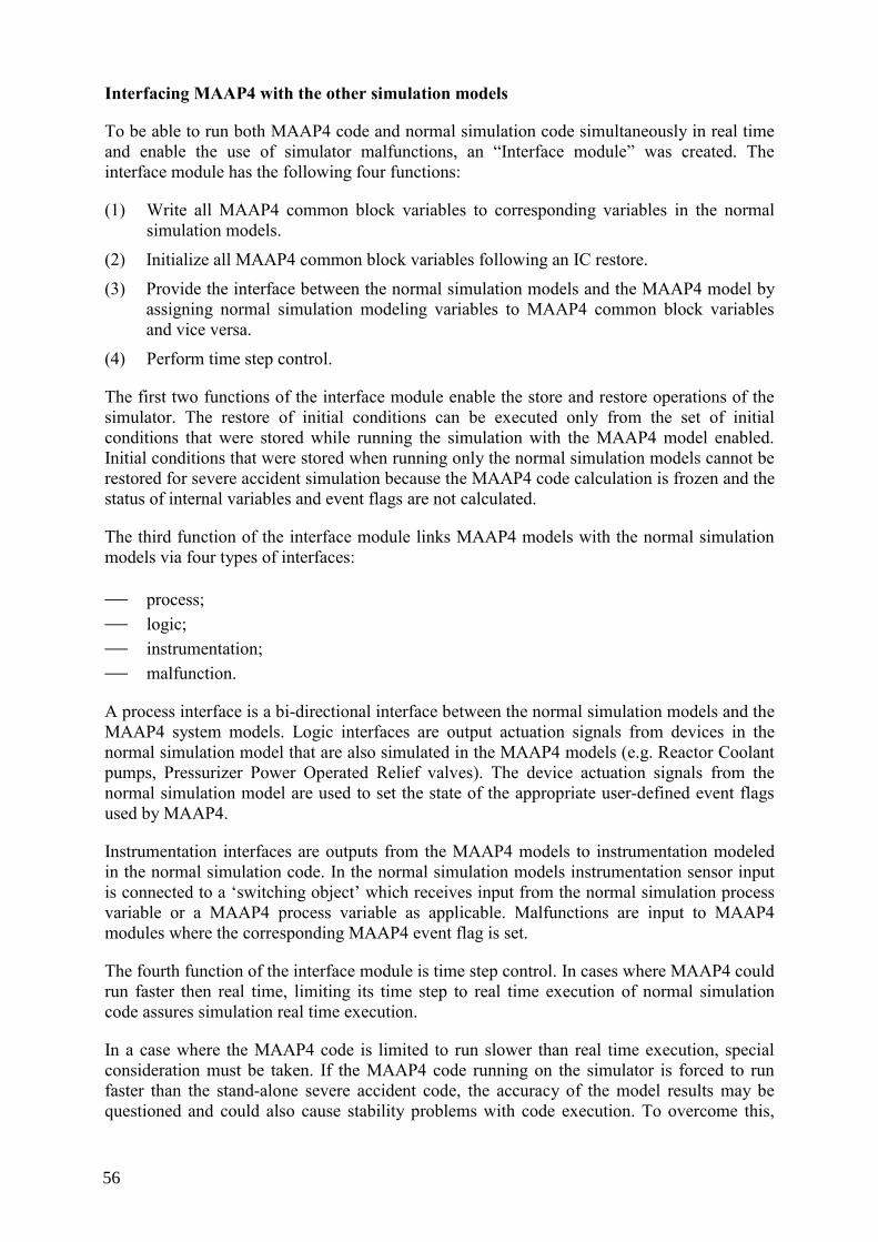
Interfacing MAAP4 with the other simulation models
To be able to run both MAAP4 code and normal simulation code simultaneously in real time and enable the use of simulator malfunctions, an “Interface module” was created. The interface module has the following four functions:
(1) Write all MAAP4 common block variables to corresponding variables in the normal simulation models.
(2) Initialize all MAAP4 common block variables following an IC restore.
(3) Provide the interface between the normal simulation models and the MAAP4 model by assigning normal simulation modeling variables to MAAP4 common block variables and vice versa.
(4) Perform time step control.
The first two functions of the interface module enable the store and restore operations of the simulator. The restore of initial conditions can be executed only from the set of initial conditions that were stored while running the simulation with the MAAP4 model enabled. Initial conditions that were stored when running only the normal simulation models cannot be restored for severe accident simulation because the MAAP4 code calculation is frozen and the status of internal variables and event flags are not calculated.
The third function of the interface module links MAAP4 models with the normal simulation models via four types of interfaces:
⎯ process; ⎯ logic; ⎯ instrumentation; ⎯ malfunction.
A process interface is a bi-directional interface between the normal simulation models and the MAAP4 system models. Logic interfaces are output actuation signals from devices in the normal simulation model that are also simulated in the MAAP4 models (e.g. Reactor Coolant pumps, Pressurizer Power Operated Relief valves). The device actuation signals from the normal simulation model are used to set the state of the appropriate user-defined event flags used by MAAP4.
Instrumentation interfaces are outputs from the MAAP4 models to instrumentation modeled in the normal simulation code. In the normal simulation models instrumentation sensor input is connected to a ‘switching object’ which receives input from the normal simulation process variable or a MAAP4 process variable as applicable. Malfunctions are input to MAAP4 modules where the corresponding MAAP4 event flag is set.
The fourth function of the interface module is time step control. In cases where MAAP4 could run faster then real time, limiting its time step to real time execution of normal simulation code assures simulation real time execution.
In a case where the MAAP4 code is limited to run slower than real time execution, special consideration must be taken. If the MAAP4 code running on the simulator is forced to run faster than the stand-alone severe accident code, the accuracy of the model results may be questioned and could also cause stability problems with code execution. To overcome this,
56
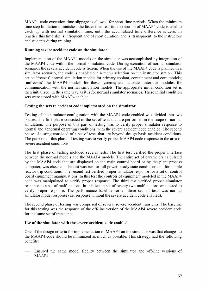
MAAP4 code execution time slippage is allowed for short time periods. When the minimum time step limitation diminishes, the faster then real time execution of MAAP4 code is used to catch up with normal simulation time, until the accumulated time difference is zero. In practice this time slip is infrequent and of short duration, and is ‘transparent’ to the instructors and students during training.
Running severe accident code on the simulator
Implementation of the MAAP4 models on the simulator was accomplished by integration of the MAAP4 code within the normal simulation code. During execution of normal simulator scenarios the severe accident code is frozen. When the use of the MAAP4 code is planned in a simulator scenario, the code is enabled via a menu selection on the instructor station. This action ‘freezes’ normal simulation models for primary coolant, containment and core models; ‘unfreezes’ the MAAP4 models for these systems; and activates interface modules for communication with the normal simulation models. The appropriate initial condition set is then initialized, in the same way as it is for normal simulator scenarios. These initial condition sets were stored with MAAP4 enabled.
Testing the severe accident code implemented on the simulator
Testing of the simulator configuration with the MAAP4 code enabled was divided into two phases. The first phase consisted of the set of tests that are performed in the scope of normal simulation. The purpose of this part of testing was to verify proper simulator response to normal and abnormal operating conditions, with the severe accident code enabled. The second phase of testing consisted of a set of tests that are beyond design basis accident conditions. The purpose of this phase of testing was to verify proper MAAP4 code response in the area of severe accident conditions.
The first phase of testing included several tests. The first test verified the proper interface between the normal models and the MAAP4 models. The entire set of parameters calculated by the MAAP4 code that are displayed on the main control board or by the plant process computer, was checked. The test was run for full power steady state conditions and for simple reactor trip conditions. The second test verified proper simulator response for a set of control board equipment manipulations. In this test the controls of equipment modeled in the MAAP4 code was manipulated to verify proper response. The third test verified proper simulator response to a set of malfunctions. In this test, a set of twenty-two malfunctions was tested to verify proper response. The performance baseline for all three sets of tests was normal simulator model response (i.e. response without the severe accident code enabled).
The second phase of testing was comprised of several severe accident transients. The baseline for this testing was the response of the off-line version of the MAAP4 severe accident code for the same set of transients.
Use of the simulator with the severe accident code enabled
One of the design criteria for implementation of MAAP4 on the simulator was that changes to the MAAP4 code should be minimized as much as possible. This strategy had the following benefits:
⎯ Ensured the same model fidelity between the simulator and off-line versions of MAAP4.
57

⎯ Enabled benchmarking of the simulator version of MAAP4 against the results of the off-line version.
⎯ Simplified future upgrades to the simulator model as a result of new off-line MAAP4 code releases.
Several years after implementation of MAAP4 on the simulator its usefulness has been proven in several areas. In the control room operator training programmes, the ability to run scenarios involving reactor core heat-up events were limited prior to the implementation of MAAP4. The normal simulation models typically have upper limitations on core temperatures (i.e. fuel and fuel cladding) due to limitations of the mathematical models used. Use of the severe accident code has enabled the validation of procedures and training of operators in the use of emergency operating procedures related to core heat-up events.
In parallel with the severe accident code implementation on the simulator, the plant also started to develop the Severe Accident Management Guidelines (SAMG) procedures. Following successful testing of the MAAP4 code on the simulator, it was used for validation of plant specific revisions to the SAMG procedures. Through this validation, the decision-making process, communications, and SAMG procedure usage were evaluated.
Severe accident models on a simulator are also useful for plant emergency response organization training. Plant technical support centres and off-site emergency response centres may be equipped with plant process computer (PPC) stations. In some cases these PPC stations can be connected to the simulator’s simulated PPC allowing simulator data to be displayed in these locations for training. The opportunity to train the plant staff on severe accident mitigation strategies has proven to be very beneficial.
58

Appendix II
PLANT PROCESS COMPUTER SYSTEM UPGRADES AT THE KSG SIMULATOR CENTRE
Project objective / reasons for upgrade
The human-machine interface (HMI) of a modern plant process computer system (PPC) differs significantly from that of older systems. Along with HMI changes, there are often improvements to system functionality such as alarm display and printing functions and transient data analysis capabilities. Therefore, the upgrade or replacement of a PPC in the reference plant will typically require an upgrade of the simulator (see Section 6.5.1 for additional information).
Several options are available for this type of project including stimulation of a replica system, or emulation, or simulation of PPC functionality within the simulation environment. To simulate or emulate a PCC, detailed knowledge of hardware and software functionality is required. This is typically vendor proprietary information, which leads to licensing and other complications. One of the added benefits of stimulating the PPC system is that the simulator can be used as a test bed for functional testing (i.e. verification and validation) of the system prior to installation in the reference plant. Some of this testing may include validation of the process curve and system diagram displays.
Over the past few years several German NPPs decided to modernize their plant process computer (PPC) systems. After the NPPs had selected the desired system to meet their requirements the question arose how to modernize the PPC systems on the corresponding simulators. Six German NPPs selected the same PPC system from the same vendor and it was desired to perform integral tests of the HMI on the simulators. In this case the vendor offered a stimulated variant of their system and it therefore made sense to choose that implementation method for upgrade of the corresponding simulators. The first simulator PPC modernization project can be considered as a prototype project for the follow-on projects. In general, from the simulator project execution perspective the implementation of several stimulated PPC systems of the same type leads to tremendous synergistic effects with respect to required manpower and project schedule.
Project description / technical solution selection
For this project the decision was made to replace the existing PPCs on each of the impacted simulators with stimulated systems based on the TELEPERM XP/OM690 system. In order to implement a project of this type the data interface system must be clarified. If there is no DCS (i.e. process control) capability required via the OM690 HMI a simple one-way data exchange interface for data transmission to the OM690 can be established. The TELEPERM XP/OM690 system offers this capability via the intelligent process element (IPE) acquisition interface definition. This interface can be simulated and implemented as a separate model running on the simulator computer system. If process control capability of the TELEPERM XP/OM690 system is required by the project, then an emulation of the plant data acquisition system should be developed and implemented. This emulation should support the various simulator operational modes (Freeze, Run, Backtrack, Snap IC, etc.) and maintenance of initial condition files.
As DCS capability of the TELEPERM XP/OM690 system was not necessary for those projects; a simulation of the IPE interface system was chosen. A detailed description of the
59

necessary IPE system was provided to the OM690 vendor, and KSG personnel developed the simulation program. KSG personnel also installed the new computer systems and other hardware while it was the responsibility of the OM690 vendor to perform a hardware system acceptance test prior to the installation of all OM690 software licenses.
A significant issue that had to be addressed by the project was delivery of the plant data model and process diagrams. If the simulator replacement project is separate from the plant project (i.e. the PPC vendor considers the plant and simulator replacements as separate projects), then the plant will typically provide the required data to the PPC vendor. This could cause an additional risk factor to the simulator project (i.e. project delay) if the data is not provided to the PPC vendor at the required time.
During the simulator upgrade project it was desirable to implement a configuration where connection to the simulation computer system from either the old or new systems could be established. This arrangement was very beneficial for testing of the new system while maintaining the simulator available for training with the old system. The most significant obstacle in this implementation was the installation of and connection to the interface hardware (i.e. monitors, keyboards, trackballs, etc.) of the new system.
Project outline/schedule
Contractually, the PPC vendor had to deliver the plant process computer software including all required licenses, and to ensure that the system replicated plant system behaviour.
It was KSG’s responsibility to install the new system hardware including the operating system and third party software. It was also the KSG’s responsibility to develop the necessary IPE system, provide the plant data model and process diagrams, and perform acceptance testing.
The project schedule was established to minimize impact on both simulator training and normal work package execution. The old plant process computer system was already connected to the main simulator computer system via network so establishing a separate network connection for the new system facilitated testing while supporting continued use of the simulator for training.
The project time schedule was roughly 9 months for initial installation of the new system and about 6 weeks for the simulator tests, including about 4 weeks for the final acceptance test. If individual process diagram validation testing is needed, then the test time required could be extended from 1–3 working days per diagram.
Project lessons learned
The lessons learned from the four plant process computer replacement projects can be summarised as follows:
⎯ It should be the responsibility of the PPC vendor to deliver the plant data model and process diagrams.
⎯ The new hardware should be ordered and installed by customer personnel as this increases the knowledge and experience of the in-house staff required for system maintainability, and allows to sign a dedicated service contract which the computer hardware vendor.
⎯ Even if the PPC vendor advertises the system as having built-in simulator capability, the various simulator operating modes need to be tested carefully. A methodology of maintaining and updating initial condition files after a data model change should also be included and tested.
60

Appendix III
EXAMPLE IMPLEMENTATION OF A CLASSROOM SIMULATOR
Implementation of a classroom simulator has many potential advantages. One of these is the ability to enhance both control room operator training and plant field operator training. The goal for this project was to improve control room operator training, field operator training, and the training of other plant personnel that do not normally receive training on the control room simulator.
Considerations for implementation of a classroom simulator
Modern NPP control room full-scope simulators typically have the capability to graphically represent the control room panels. These kinds of panels are often referred to as ‘glass panels’, ‘soft panels’ or ‘panel graphics’. When considering the project to incorporate the NPP control room simulator into the field operators training, the existing simulator capability in the area of graphical panels needed to be examined. If an upgrade or modernization project for the full-scope simulator is planned then implementation of a classroom simulator might be considered in the scope of such a project.
For the project presented here the full-scope simulator is running on a UNIX based operating system and the simulator environment already includes panel graphics. Simulator capabilities and modeling scope were evaluated and considered adequate for this project.
How the instructors and students would interface with the classroom simulator was then evaluated. There were several options that were considered:
⎯ Training is performed in the classroom that is equipped with PC workstations linked to the simulator host computer system.
⎯ Training is performed on the existing simulator instructor station. ⎯ Training is performed in the classroom using a PC workstation and projector coupled
with an Interactive Whiteboard.
The use of an Interactive Whiteboard was selected as the most appropriate interface based upon the following considerations:
⎯ Trainees can manipulate the equipment directly from the panel graphics without the need to use a mouse or keyboard.
⎯ Easy connection with the simulator host computer system. ⎯ Possibility to connecting the NPP LAN with the Interactive Whiteboard. ⎯ The large display area of the Interactive Whiteboard allows display of multiple screens
or windows at the same time (one with the simulator; others with power point presentation, drawings, procedures, etc.).
When reviewing the field operator training programmes and comparing them to the control room operator training programmes, a discrepancy in quality and level were identified. Also training in the area of operating crew soft skills was considered not well covered. Based on these two observations the decision to incorporate the use of the simulator models into field operator training was made.
61

Classroom hardware configuration
The hardware configuration used in this project is schematically shown in Fig. 1.
Fig. 1. Classroom hardware configuration.
The simulator host is connected to the instructor station PC via a simulator network connection. This PC runs Windows NT© and Emulation software for the UNIX environment to be able to communicate with the simulator host. The other PC is running on the Windows 98© operating system and is connected to the plant local area network. The software drivers for the Interactive Whiteboard are installed on both of these PCs.
The two PCs are connected to a VGA switcher (i.e. KVM switch) and the Interactive Whiteboard driver module. The VGA switcher enables the use of one mouse, keyboard, and monitor for both of PC’s and displays the output of the selected PC via ceiling projector onto the Interactive Whiteboard. Both PCs are also connected to the Interactive Whiteboard interface module, which operates the board.
The configuration with two PCs might be avoidable. In this particular case the plant network and the simulator network are not connected due to network security reasons. If the two networks could be connected then only one PC could be used and the VGA switcher would be unnecessary.
Project schedule and implementation
The schedule for this project was divided into two separate phases. The first phase covers the hardware solution of the project (procurement, installation and setup, etc.). The second phase
62

deals with the scope of the modeled simulator graphical panels. First phase of project was straightforward and easier to achieve.
The second phase of the project was more complex and harder defined up front. In the case where existing simulator capabilities are used, expansion of the soft panels to include local operating panels is required, and the work will be performed in-house, the project schedule may span one or more years. For this project in-house resources were limited and funds were unavailable for vendor support. Therefore the project is being accomplished using a step-by-step approach. It was decided that for each new training segment one local graphical panel would be modeled, so that the current field operators training needs could be met. On this pace the majority of local panels will be modeled in the next 5 to 6 years.
Limitations in the scope of the systems simulated and the simplifications of the modeled components are the main difficulties encountered when modeling the graphical local panels. Typically the simulated scope of the system controlled from local panels is not sufficient. To be able to adequately represent the local panel items some additional instrumentation, valve controls, pump controls need to be simulated. Although a particular component may already be part of the existing scope of simulation, the simulated code of component might be too simplified to support adequate representation on the local panel. In our experience it typically takes at least twice as long to expand the scope of simulation as it does to create the local soft panel graphics.
Project benefits
The use of the simulator for training of personnel other than control room operators can effectively support the learning objectives of the particular training programme. Classroom simulator capability now allows the field operators to perform their actions independently of instructor input (i.e. they interact with the panel graphics to perform control switch manipulations as they would in the plant) as a part of licensed operator simulator scenarios. This allows the response to equipment malfunctions and consequence of improper actions to be demonstrated.
63


Appendix IV
UPGRADE OF THE AUDIO/VIDEO RECORDING SYSTEM ON THE CERNAVODA NPP SIMULATOR
The audio-video recording system is used in the simulator control room for:
⎯ recording simulator examinations used for authorization or reauthorization of the operators or for ordinary training sessions;
⎯ detailed observation of the real-time actions of the operators as they operate controls on various sections of the control boards;
⎯ post-scenario analysis and critique of operator performance.
The technical solution chosen for this project was to use a special PC that functions as a Digital Video Recorder (DVR). This PC contains a special purpose video and sound card, which enables the DVR functionality.
Audio input comes from six fixed microphones mounted into the ceiling and from three wireless lapel microphones worn by the operators.
Color video input is provided to the recording system from the following ceiling-mounted video cameras:
⎯ one omni-directional dome camera; ⎯ three fixed cameras which each provide an overhead view of one third of the panels; ⎯ one fixed camera for a general overview of the simulator main control room; ⎯ ten fixed miniature cameras for the angled sections of the panels.
The main camera in the system is the dome camera. This camera has 360° continuous pan rotation and 23X optical zoom and 10X electronic zoom enabling a wide angle or closeup view of each section of the control panels. These camera functions are controlled from a special purpose keyboard located in the instructor control room near the monitor of the DVR PC.
The DVR PC runs a software application that records the video signals from all fifteen cameras along with three channels of audio in the high quality compressed DivX format. System storage capacity (i.e. hard drive storage) is expandable beyond 500 Gb. All system equipment is rack-mounted in a 19” rack located in the instructor control room.
An advantage of choosing this all-digital solution is that output from the system can also be served across the plant Intranet to client PCs running the same video application software. This capability allows plant managers and instructors to observe simulator training in progress from a remote location. It is also possible to record the mixed video/audio signal to DVD media if desired.
Working with the supplying vendor the upgraded A/V system was installed and operational in two just days. Only one significant technical difficulty was encountered during installation and testing. The original design of the system included only the six fixed ceiling-mounted microphones. During acceptance testing it was discovered that ceiling vibrations from the building air conditioning system negatively impacted the audio quality from these microphones.
65

Consequently, it was necessary to add the three wireless lapel microphones to the system to achieve adequate voice quality. All system microphones were grouped into three channels:
⎯ one channel for all six fixed microphones mixed together; ⎯ one channel for all three wireless microphones mixed together; ⎯ one channel for all nine microphones mixed together.
When a recording is played any of the three sound channels can be selected along with the video from one or more cameras.
In terms of project development, a key point of the project success was choosing a capable equipment vendor that had previous experience with installing this type of A/V system. The upgraded system has been in service for nearly three years and has required no special maintenance, only some minor system fine tuning.
Additional detail on this project is contained in document number 30 on the accompanying CD-ROM.
66

Appendix V
EXAMPLE DESIGN SPECIFICATION DOCUMENT
1. INTRODUCTION
This specification establishes the technical and general requirements for a PC- based rehost of the XXXX Simulator. The selected vendor will provide a Windows NT© executive for this project. Engineering development tools are optional in this specification but will be evaluated for purchase by the customer simulator staff.
2. SCOPE OF SUPPLY
2.1. Background
The current simulator computer complex consists of one Encore 67 Multi-Sel system (one host and one node) and one SUN Ultra-Sparc 1 UNIX workstation and several other computers (TGIS, Core model, Foxboro DCS, PPC, etc.). The Encore’s reflective memory system is utilized for communication among the Encore host, node and SUN Ultra-Sparc 1 workstation. A second set of computers (Encore 67 and SUN Ultra-Sparc 1) is used for software development and as a backup to the main simulation computers. Both simulation and development computers can link to the simulator I/O system via the peripheral switch. Currently Simulator I/O is separated into two parts, DI, LO and AO are controlled by Singer’s UNILINK master controller and linked to the Encore 67 via HSD, AI is controlled by TMI’s master controller linked to the SUN Ultra-Sparc 1 via SCSI. The simulation tasks which reside on the Encore 67 are the early Singer-Link DATAPOOL executive system. The executive system which resides on the SUN Ultra-Sparc 1 is a UNIX version of an “S3-like” executive system.
The rehost will be accomplished in several stages. The first stage involves replacing the SUN Ultra-Sparc 1 with a Windows NT© workstation/server which will have a SCSI interface to the TMI master controller as well as a connection to the Encore reflective memory system (or other vendor proposed alternative). The second stage involves the systematic migration of the existing simulation modules to the NT server from the Encore 67. This is an ongoing project since much of the existing assembly language code must be re-written in FORTRAN. The final stage of the project is removal of the Encore 67 computers. Along with several other issues this final stage cannot be completed until the instructor station is running from the NT server.
2.2. Replacement hardware
The customer will purchase the replacement simulation and development PC server systems and engineering workstations. Windows NT Server© will be pre-installed on the servers and Windows NT Workstation© will be pre-installed on the engineering workstations. In response to this bid spec the vendor must specify a recommended hardware configuration for use with their software. Vendor must also specify third party software (if any) that must be purchased to work with their software.
2.3. Executive software and supporting routines
The replacement executive software shall:
67

(1) Meet all specifications of the new computer platform and run on Microsoft Windows NT 4.0© or later.
(2) Be capable of establishing a data link (utilizing the existing Encore reflective memory system or some other cost effective vendor specified alternative) to share the data in DATAPOOL with the Encore 67 host and node. This data link shall include floating point format conversion, bit manipulation and byte swapping for big versus little endian data interface.
(3) Be compatible with and capable of performing I/O utilizing the TMI master controller (i.e. I/O Override, switch check, DORT, etc.).
(4) Be capable of acting as a slave executive under the control of the master executive and TGIS (instructor station) running on the Encore 67 during the migration stage of the project. TGIS commands that must be supported include Run, Freeze, Reset, Snapshot and Backtrack.
(5) Be capable of performing reset to and snap of 100 ICs (initial conditions) as well as storage of 120 backtrack records at an interval selected by the instructor station (minimum interval shall be 30 seconds). Also be capable of resetting to any backtrack condition saved after the start of a scenario.
(6) Have multi-executive capability. Provide multi-processor synchronization and control. Provide real-time execution scheduling of all models at their required rates.
(7) Accept, schedule, and run FORTRAN modules ported from the Encore 67 with minor modifications.
(8) Provide a real time debugging tool to monitor and modify the simulation variables and constants while the simulator is running as well as control the simulation (run, freeze, reset, snapshot, step, slow, fast, and variable rate). Vendor software shall also provide simulation module status as well as provide the capability of moving modules in or out of execution.
(9) Be capable of intercepting model violations, mathematical errors, and posting of diagnostic information, i.e. attempted execution of illegal or undefined instructions, memory privilege violations, arithmetic exceptions, model looping and stall conditions.
(10) Include a database manager to maintain the simulator software database.
(11) Provide a software configuration management system to maintain all simulator software. The configuration management system shall provide a secure environment for building development and training loads as well as provide for load version control and modification tracking.
(12) Provide simulation module timing statistics.
The source code of the executive system software shall be provided to the customer. Exempted from this requirement is the source code for any “Engineering Tools” offered for purchase by the vendor or which may come “bundled” with the executive software.
68

2.4. Training
The vendor must specify and provide a course of instruction for up to 5 customer support personnel. Course will be comprehensive vice introductory in nature and cover all functions of the executive software as well as the usage of any “Engineering Tools” that may be purchased by the customer. It is preferable that training be conducted at the customer’s Training Center. If training must be conducted at a vendor facility the customer will pay for student expenses (lodging, travel, meals, etc.).
2.5. Warranty/software upgrades
The vendor shall warrant the software to be free from defect for a period of two years. The vendor shall also provide software revisions or upgrades free of charge to the customer for this same two-year period.
3. ACCEPTANCE TESTING
Upon completion of the installation, an acceptance test will be conducted by the customer simulator support staff. This test will include as a minimum: porting of existing models and ICs on the SUN Ultra-Sparc 1 to the PC servers and verification of proper integration/communication with the Enore 67 to build a load, save a load, and restore a previously saved load. Several plant transients will also be run. Simulator response will be verified by comparing selected trends created prior to the installation to those produced following the installation.
4. DOCUMENTATION
A final design document shall be supplied in printed copy and one set of electronic media (Microsoft Word© format) for review and comment within 30 days of installation completion. The documentation shall be written in a clear, easy to understand manner. For each program, module, or subprogram used, a Program Design Document shall be supplied. Included within this document shall be:
(1) Name of the program.
(2) Narrative description of the purpose of the program and the method of implementation.
(3) Source file name.
(4) Name by which the program is called or activated.
(5) Names of any required program libraries.
(6) Names of any required data files.
(7) Method to update the programs, including scripts, makefile, job control streams, references to other affected software or data, and any other information required to perform successful maintenance on the programs.
(8) Explanation of any error messages which are unique to the programs.
(9) Data formats.
(10) An alphabetized listing of all symbols used which includes the type, dimension, short description and units in which the symbol is computed.
69

(11) Pseudo code or program design language to document the software. A consistent style of indentation shall be used to show the range of various control constructs.
(12) Names of all subroutines used.
5. USER MANUAL
A user manual shall be supplied in printed copy and one set of electronic media (Microsoft Word© format) prior to customer acceptance of the completed installation. The manual shall describe the operation of each function and provide guidelines for maintenance and support of the executive system. If any “Engineering Tools” are included in purchased software package, a user manual is required for each of them.
6. INSTALLATION
The vendor is responsible for installing all hardware and software associated with the new computer and the new executive system. This includes interfacing with the existing Encore 67 and TMI master controller. The installation of the new computer system is planned to occur in two phases in order to minimize the impact on training and software development.
Phase one will be the test installation of the new computer. It will be installed and connected to the existing development system and connected to the simulator via the existing peripheral switch. This configuration will allow for adequate testing of the new hardware/software combination while meeting training commitments with the present computer system. Phase two will begin upon completion of acceptance testing on the development system and consist of installation of the new hardware/software combination on the training computer system.
7. SCHEDULE
The vendor shall provide a proposed project schedule with the quote. The vendor will develop and customer will approve a finalized project schedule after the contract is awarded. Work which does not require the use of the simulator can be conducted during normal working hours. Work requiring access to the simulator may require working on the backshift.
8. TERMS AND CONDITIONS
Contract terms and conditions other than those addressed in this bid specification will be provided by the Seabrook Purchasing Department. Bid replies must be received by XX/XX/XXXX to be considered.
70

REFERENCES
[1] INTERNATIONAL ATOMIC ENERGY AGENCY, Recruitment, Qualification and Training of Personnel for Nuclear Power Plants, Safety Standards Series NS-G-2.8, Safety Guide, IAEA, Vienna (2002).
[2] INTERNATIONAL ATOMIC ENERGY AGENCY, Nuclear Power Plant Personnel Training and its evaluation, Technical Report Series No. 380, IAEA, Vienna (1996).
[3] INTERNATIONAL ATOMIC ENERGY AGENCY, Simulators for Training Nuclear Power Plant Personnel, IAEA-TECDOC-685, IAEA, Vienna (1993).
[4] INTERNATIONAL ATOMIC ENERGY AGENCY, Selection, Specification, Design and Use of Various Nuclear Power Plant Training Simulators, IAEA-TECDOC-995, IAEA, Vienna (1998).
[5] INTERNATIONAL ATOMIC ENERGY AGENCY, Use of control room simulators for training of NPP personnel, IAEA-TECDOC-1411, IAEA, Vienna (2004).
[6] INTERNATIONAL ATOMIC ENERGY AGENCY, Application of Simulation Techniques for Accident Management Training in Nuclear Power Plants, IAEA-TECDOC-1352, IAEA, Vienna (2003).
[7] ANSI/ANS-3.5, Nuclear power plant simulators for use in operator training and examination, American Nuclear Society, La Grange Park, Illinois, USA (1985, 1993, 1998).
71


LIST OF ABBREVIATIONS
ANSI – American National Standards Institute
ANS – American Nuclear Society
ATP – Acceptance Test Procedure
BOC – Beginning of Cycle
BOP – Balance of Plant
BWR – Boiling Water Reactor
CAN – Controller Area Network
CPM – Critical Path Method
CPU – Central Processing Unit
DCS – Digital Control System (also Distributed Control System)
EOC – End of Cycle
EPRI – Electric Power Research Institute (USA)
ESF – Engineered Safety Feature
FAT – Factory Acceptance Testing
GUI – Graphical User Interface
HMI – Human-Machine Interface
I/O – Input / Output
IC – Initial Condition
INPO – Institute of Nuclear Power Operations (USA)
IT – Information Technology
LAN – Local Area Network
M/A station – Manual/Auto control station (i.e. process controller)
MAAP – Modular Accident Analysis Program
Mbps – Megabits per second
MMI – Man-Machine Interface
MOC – Middle of Cycle
73
MOX – Mixed Oxide fuel (UO2+PuO2)
NPP – Nuclear Power Plant
NSSS – Nuclear Steam Supply System
OEM – Original Equipment Manufacturer
OS – Operating System
PC – Personal Computer
PERT – Performance Evaluation and Review Technique
PPC – Plant Process Computer
Pre-FAT – Pre-factory Acceptance Testing
PWR – Pressurized Water Reactor
RFT – Ready for Training
SAMG – Severe Accident Management Guidelines
SAT – Site Acceptance Testing
TCP/IP – Transmission Control Protocol/Internet Protocol
TECDOC – Technical Document
V&V – Verification and Validation
VGA – Video Graphics Array
74

Annex I
CONTENTS OF THE ACCOMPANYING CD-ROM
No Country Title TECDOC Section
1 Canada DCS Translation Tool: Faster & better than ever
6.4
2 UK BNFL Magnox – Upgrades & Enhancements
6.1, 6.3, 6.6
3 Spain Changing the Simulator Steam Generator model
6.1
4 US WNP-2 Core Model Upgrade 6.1
5 US DCS Upgrades for Nuclear Power Plants: Saving Money and Reducing Risk through Virtual-Stimulation Control System Checkout
6.4
6 Germany Digital I&C System Pre-Tests using Plant Specific Simulators
6.4
7 Bulgaria A Brief Account of Kozloduy 6 Full-scope Replica Control Room Simulator Upgrade Experience
6.1, 6.6, 6.7
8 Russia Leningrad NPP Full Scope Simulator Upgrade for PPC HMI Improvement and Operator Support Systems Development and Testing
6.4, 6.5
9 UK Project Managing Your Simulator DCS Upgrade
6.4
10 US Securing Budget for and Implementing Your Significant Simulator Upgrade: The Fermi Experience
2.0, 3.0, 4.0 5.0, 6.1, 6.3, 6.6
11 Russia Outline of ATE Novovoronezh Training centre simulator V-187 upgrade project
6.1, 6.3, 6.5, 6.6
12 China Upgrade of Daya Bay Full Scope Simulator 6.3
13 Russia RBMK Full Scope Simulator Gets Virtual Refueling Machine
6.1
14 Ukraine Simulator Configuration Maintenance 5.4
75

No Country Title TECDOC Section
15 US Simulator & Simulation Trends 3.0, 4.0, 6.1,6.2,6.3, 6.4,6.5,6.6, 6.8
16 France Example of Software Configuration Management Model
5.4
17 US San Onofre 2/3 Simulator: The Move From UNIX to Windows
6.3, 6.5, 6.6
18 South Africa Overcoming Challenges: The Koeberg simulator project
6.3, 6.6
19 US Vermont Yankee Simulator BOP Model Upgrade
6.1
20 France VVER-440 Training Simulators Upgrades – Experience of CORYS -TESS
6.4, 6.7
21 Canada Review Of DCS Implementation techniques for NPP Control Room Simulators
6.4
22 China Qinshan 300 MWE NPP Full Scope Simulator Upgrade
6.3, 6.4, 6.6
23 Czech Republic
Upgrade Framework and Use of FSS in Czech Republic
6.4, 6.8
24 Finland Utilization of the Simulators in I&C Renewal Project of Loviisa NPP
6.4
25 France SARIE Upgrade: Nuclear Reactor and Water Systems “Engineering and Training” Simulator
2.0, 3.0, 4.0 5.0, 6.1, 6.8
26 Germany D1+ Simulator: A Cost and Risk Optimized Approach to Nuclear Power Plant Simulator Modernization
2.0, 3.0, 4.0 5.0, 6.1, 6.4, 6.5, 6.7
27 Germany Overview of KSG-GFS simulator Centre 2.0, 3.0, 4.0 5.0
28 Japan Upgrading BWR Training Simulators for Annual Outage Operation Training
6.1
29 Lithuania Modernization of Ignalina NPP Full-scope Simulator
6.1, 6.5
76

No Country Title TECDOC Section
30 Romania Audio & Video Monitoring System for a Nuclear Power Plant Control Room Simulator
6.8
31 Slovakia Regulatory Authority Requirements for Full-scope Simulator Upgrading in the Slovak Republic
2.3
32 Spain The Spanish Experience in NPP Simulators Upgrading
2.0, 3.0, 4.0, 5.0, 6.1, 6.2, 6.3, 6.4, 6.8
33 Spain Trillo NPP Full-scope Replica Simulator: The Last Great NPP Simulation Challenge In Spain
2.0, 3.0, 4.0, 5.0, 6.1, 6.2, 6.3, 6.4, 6.8
34 Spain Laguna Verde Simulator: A New TRAC-RT Based Application
6.1
35 Spain TRAC Real-time: A High Fidelity Solution for NSSS Modeling – Application to Lungmen and Grafenrheinfeld NPP Simulators
6.1
36 Romania Digital Control Computer Upgrade at the Cernavoda NPP Simulator
6.4
37 Spain Example DR Form for the Laguna Verde Simulator
5.0
38 Pakistan Example DR For CHASNUPP 5.0
39 France SIROCCO Project: 15 Advanced Instructor Station Installations
6.6
40 Ukraine Ukrainian NPPs Full-scope Simulators 6.3, 6.4, 6.5
41 US Modernization of the Seabrook NPP Simulator: “Assembly Code to C++”
2.0, 3.0, 4.0, 5.0, 6.1, 6.2, 6.3, 6.4, 6.6, 6.8
77


CONTRIBUTORS TO DRAFTING AND REVIEW
Ashy, O. Western Services Corp., United States of America
Boire, R. L-3 Communications MAPPS Inc., Canada
Cassidy, T.C. FPL Energy - Seabrook Station, United States of America
Češnjevar, D. Krsko Nuclear Power Plant, Slovenia
Dercze, L. Paks NPP ltd., Hungary
Dinkov, Y. Kozloduy NPP, Plc., Bulgaria
Galle, M.K. Farley Nuclear Plant, Southern Nuclear Company, United States of America
Glukhanich, B. National Nuclear Energy Generating Company “Energoatom”, Ukraine
Groshev, O. NPP OSI, Ukraine
Holl, B. KSG Kraftwerks-Simulator-Gesellschaft mbH, Germany
Junaid Ahmed Syed Informatics Complex (PAEC), Pakistan
Kazennov, A. International Atomic Energy Agency
Kelin Qi Research Institute of Nuclear Power Operations, China
Kershner, R. L-3 Communications MAPPS Inc., United States of America
Kozera, J.K. EDF Branche Production Ingenierie, France
Krivanek, Z Dukovany NPP, Czech Republic
Liaschenko, S. NVUTC, Russia
Lungoci, S. Societatea Nationala Nuclearelectrica SA, Cernavoda Nuclear Power Plant, Romania
Mirensky, M. GSE Power Systems, United States of America
Muller, J. Kernkraftwerk Gosgen-Daniken AG, Switzerland
Murata, F. BWR Operator Training Center Corporation, Japan
Nakajima, A. BWR Operator Training Center Corporation, Japan
Ortega Pascual, F. TECNATOM, S.A., Spain
Peradze, K. Ignalina NPP, Lithuania
79

Porkholm, K. Fortum Nuclear Services Ltd., Finland
Roth, H. KSG Kraftwerks-Simulator-Gesellschaft mbH, Germany
Roth, P. CORYS T.E.S.S. (Training and Engineering Support Systems), France
Sarode, D.N. Nuclear Power Corporation of India Ltd., India
Shafaat Ali CHASNUPP, Pakistan
Sivokon, V. Russian Research Centre “Kurchatov Institute”, Russia
Szabó, V. Nuclear Regulatory Authority of the Slovak Republic, Slovakia
Tiihonen, O. Technical Research Centre, Finland
Vamos, G. International Atomic Energy Agency
Yunfeng Ding China Atomic Energy Authority, China
Consultants’ Meeting
Vienna, Austria: 14–17 March 2005
Technical Meeting
Essen, Germany: 19–22 September 2005
80