guidelines for the successful installation and …
TRANSCRIPT

The successful start-up and operation of a pneumatic sand conveying system is not only based on the functional design features of the system but also on following specific system based installation instructions from the vendor and applying proven work procedures. When contracting for the installation of a pneumatic conveying system the owner depends on the installing contractor to not only install the components properly but also perform the start-up function of the entire system and turn it over to the owner as a fully and properly functional system.
Since the preferred method of pneumatic conveying of sand is by a pressure or dense phase system, rather than a vacuum or dilute phase system, we will concentrate in this article on a dense phase type pneumatic sand conveying system. The basic difference between a dense phase system and a vacuum or dilute phase system is the velocity of the sand travelling thru the piping system whereby in a vacuum or dilute phase system the sand travels in a fluidized state at around 4000 feet per minute while in a well designed dense phase system the sand travels in plugs or slugs at design velocities of only 400 to 1500 feet per minute. Naturally, the lower velocities in a dense phase system minimize pipe wear and sand degradation and the generation of dust from the impingement of the sand grains on the pipe walls.
It is most helpful if the installing contractor’s personnel are familiar with the basic operating principles of the conveying system so that they, in addition to the installation instructions of the vendor, can use their own intuition to provide the necessary work procedures for a successful project completion.
Each vendor of pneumatic sand conveying systems probably has their own installation instructions, however, in addition to or the absence of such directions the following main topics should be considered for a successful installation;
1. Location and positioning of transporter blow tank Always consider the location of the transporter blow tank and the optimum routing of the piping system to the receiving bin(s). Normally the transporter blow tank is being fed with sand by gravity from an overhead silo or bin. Two shut-off valves are needed in the feed pipe connection, one (hand operated) to isolate the blow tank from the sand feed (for maintenance purposes) and one (automatically controlled from the transporter controls) functioning as part of the fill cycle. No external loads should be transferred to the transporter. Transporter should not be lagged to the floor until the entire installation is complete and the required pressure test of the piping system has been completed satisfactorily.
2. Number of receiving bins for sand and isolation/fill valves Determine and consider the actual number and relative location of receiving bins to the transporter blow tank and for multiple receiving bins evaluate proper diverter piping with an isolation/fill valve for each receiving bin. To operate properly the transporter system should deliver sand to only one receiving bin at a time and all fill/isolation valves for the remaining bins should be closed except the fill valve for the receiving bin to be filled with sand. If a transport system has only one receiving bin/silo then only one end discharge fitting is required, without the need of an isolation/ fill valve.
CHRIS DOERSCHLAG Consultant PALMER MANUFACTURING & SUPPLY, INC. – KLEIN DIVISION
ARTICLE TAKEAWAYS:• Dense phase vs. dilute phsae systems
• Location–blow tank, bins, and pipe run
GUIDELINES FOR THE SUCCESSFUL INSTALLATION AND OPERATION OF A PNEUMATIC SAND CONVEYING SYSTEM
18
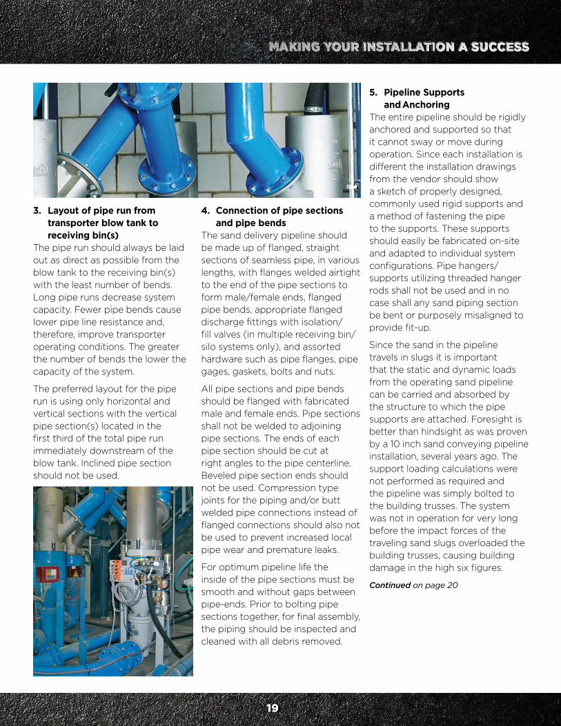
3. Layout of pipe run from transporter blow tank to receiving bin(s) The pipe run should always be laid out as direct as possible from the blow tank to the receiving bin(s) with the least number of bends. Long pipe runs decrease system capacity. Fewer pipe bends cause lower pipe line resistance and, therefore, improve transporter operating conditions. The greater the number of bends the lower the capacity of the system.
The preferred layout for the pipe run is using only horizontal and vertical sections with the vertical pipe section(s) located in the first third of the total pipe run immediately downstream of the blow tank. Inclined pipe section should not be used.
5. Pipeline Supports and Anchoring The entire pipeline should be rigidly anchored and supported so that it cannot sway or move during operation. Since each installation is different the installation drawings from the vendor should show a sketch of properly designed, commonly used rigid supports and a method of fastening the pipe to the supports. These supports should easily be fabricated on-site and adapted to individual system configurations. Pipe hangers/supports utilizing threaded hanger rods shall not be used and in no case shall any sand piping section be bent or purposely misaligned to provide fit-up.
Since the sand in the pipeline travels in slugs it is important that the static and dynamic loads from the operating sand pipeline can be carried and absorbed by the structure to which the pipe supports are attached. Foresight is better than hindsight as was proven by a 10 inch sand conveying pipeline installation, several years ago. The support loading calculations were not performed as required and the pipeline was simply bolted to the building trusses. The system was not in operation for very long before the impact forces of the traveling sand slugs overloaded the building trusses, causing building damage in the high six figures.
Continued on page 20
4. Connection of pipe sections and pipe bends The sand delivery pipeline should be made up of flanged, straight sections of seamless pipe, in various lengths, with flanges welded airtight to the end of the pipe sections to form male/female ends, flanged pipe bends, appropriate flanged discharge fittings with isolation/fill valves (in multiple receiving bin/silo systems only), and assorted hardware such as pipe flanges, pipe gages, gaskets, bolts and nuts.
All pipe sections and pipe bends should be flanged with fabricated male and female ends. Pipe sections shall not be welded to adjoining pipe sections. The ends of each pipe section should be cut at right angles to the pipe centerline. Beveled pipe section ends should not be used. Compression type joints for the piping and/or butt welded pipe connections instead of flanged connections should also not be used to prevent increased local pipe wear and premature leaks.
For optimum pipeline life the inside of the pipe sections must be smooth and without gaps between pipe-ends. Prior to bolting pipe sections together, for final assembly, the piping should be inspected and cleaned with all debris removed.
19

6. Source and quality of compressed air To operate the transporter properly and push the sand slugs thru the pipe run requires compressed air. The transporter should be connected to a compressed air receiver tank, to dampen the cyclical air demand from the transporter, with the air supply originating at the plant’s specified location or a separate dedicated air compressor for the system, using pipe sizes and configurations as proposed by the transporter vendor. Most dense phase sand transporter systems require regulated, dry, oil free air (dew point of - 40 degrees F) at 85 to 100 psi.
7. Electrical connections and controls Electrical power feed to the transporter control panel should be checked to assure that the plant’s power supply matches the primary voltage and load demands of the transporter control panel.
Electrical connections should be wired, with the appropriate wire numbers, as shown on the conduit and cabling schedule/electrical drawings, prepared by the vendor, permanently attached to each wire on both ends, from the transporter control panel to a junction box near the receiving bin isolation/fillvalve and respective high level probes mounted in the receiving bin(s)/silo(s) and level probe in the transporter inlet sand supply pipe stub.
8. Dust Collection The air used to push the sand from the blow tank to the receiving bin(s) must be vented from each receiving bin/silo to a dust collector before
being discharged to atmosphere. Each receiving bin/silo should, therefore, be equipped with a means of collecting and filtering the vent air. For a transporter system with only one receiving bin, a simple bin top dust collector can be used.
The dust collector for a multiple bin system must have its own fan and will most likely run continuously. The transporter, however, does not operate continuously and provisions must be made for “bleed-in” air when the transporter is at rest.
9. Final inspection of installation and pressure testing Upon completion of all field installation, a final inspection should be made of the entire sand piping system prior to testing and operation. This final inspection should be performed to ensure that all electrical connections have been completed, compressed air supply is ready for operation, dust collection requirements have been satisfied and all piping is installed and supported properly and is ready for testing and operation.
10. Pressure Test After the piping system has been installed and is ready for operation a 24 hour pressure test of the piping system should be performed at the maximum air pressure the system will be exposed to during normal operation. Any air leaks found in the piping system, especially at each flanged pipe joint, shall be repaired and the pressure test for that piping system repeated.
Operating the transporter system initially without first performing a satisfactory pressure test should not be attempted to eliminate any operating problems.
11. Start-up Upon completion of the installation, final inspection and with sand supply available to feed the transporter, start-up of the system can be initiated following the detailed start-up instructions specified in the vendor’s Operation and Maintenance manual.
20
Contact: CHRIS [email protected]

Tener éxito en la puesta en marcha y posterior operación de un sistema de transporte neumático de arena, se basa no sólo en las características de diseño del sistema, sino también en seguir las indicaciones del proveedor para ese sistema específico y aplicar procedimientos de trabajo probados. Al contratar la instalación de un sistema de transporte neumático, quien compra depende de su contratista no sólo para que instale correctamente los componentes sino también para que realice la puesta en marcha y le entregue al comprador un sistema funcionando adecuadamente.
Como el método de transporte neumático de arena preferido es de tipo fase densa o sistema a presión, este artículo se concentrará en este tipo y no en el de tipo fase diluta o vacío. La diferencia básica entre un sistema de fase densa y uno de fase diluta o vacío es la velocidad con la que viaja la arena a través del sistema de tuberías donde en un sistema de vacío o fase diluta la arena viaja fluidizada a 4000 pies por minuto (20 m/s) mientras que en un sistema de fase densa bien diseñado la arena viaja en tapones o cúmulos a velocidades de diseño de solamente 400 a 1500 pies por minuto. (de 2 a 8 m/s) Naturalmente, las menores velocidades en un sistema en fase densa minimizan el desgaste de las cañerías, la degradación de la arena y la generación de polvo debido al impacto de los granos de arena contra las paredes de las tuberías.
Lo que más ayuda a una instalación exitosa es que el personal del contratista esté familiarizado con los principios básicos de operación de un sistema de transporte de arena, de modo que, además de seguir las instrucciones de instalación del fabricante, puedan guiarse por su intuición para entregar los procedimientos de trabajo para completar el proyecto exitosamente.
Cada vendedor de sistemas de transporte neumático de arena tiene probablemente su propio conjunto de instrucciones de instalación, a pesar de esto, para complementar o en el caso de que no hubiera directivas, deben considerarse los siguientes puntos principales para una instalación competente:
1. Ubicación y orientación del tanque de soplado Siempre considere la ubicación del tanque de soplado del sistema de transporte de arena y la ruta óptima del sistema de tuberías hasta los colectores o tanques receptores. Normalmente el tanque de soplado se alimenta de arena por gravedad, desde un silo o recipiente colocado justo sobre él. Se necesitan dos válvulas de corte en la conexión de la alimentación, una, manual, para aislar al tanque de soplado de la alimentación de arena (con objeto del mantenimiento) y otra, controlada automáticamente por los controles del transportador, funcionando como parte del ciclo de llenado. No deben transferirse cargas externas al transportador. El transportador no debe abulonarse al piso hasta que se haya terminado la instalación completa y la prueba de la presión requerida haya sido completada satisfactoriamente.
2. Numero de colectores para arena y válvulas de bloqueo/ llenado Determine y considere la cantidad real y ubicación relativa de los tanques receptores del tanque de soplado del sistema de transporte y, en el caso de múltiples colectores, evalúe colocar tuberías de derivación apropiadas con una válvula de bloqueo/llenado para cada tanque receptor. Para operar adecuadamente el sistema de transporte debe entregar arena a un tanque colector por vez y todas las demás válvulas de corte deben estar cerradas a excepción de la válvula de llenado del recipiente que va a ser llenado con la arena. Si un sistema de transporte tiene solamente un colector/silo, entonces se necesita solamente un accesorio de descarga
CHRIS DOERSCHLAG Consultant PALMER MANUFACTURING & SUPPLY, INC. – KLEIN DIVISION
PUNTOS SOBRESALIENTES DEL ARTÍCULO:• Sistemas de fase densa vs fase diluta
• Ubicación del tanque de soplado, silos y tuberías
GUÍA PARA UNA INSTALACIÓN Y OPERACIÓN DE UN SISTEMA DE TRANSPORTE NEUMÁTICO DE ARENA
78

en un extremo, sin necesidad de una válvula de corte/llenado.
3. Layout del trazado de cañerías desde el tanque soplador a los colectores El trazado de las cañerías debe hacerse siempre de la forma más directa que sea posible desde el tanque soplador hasta los colectores con el menor número posible de codos. Recorridos largos bajan la capacidad del sistema. Poner menos curvas da como resultado menos resistencia de la línea de cañerías, mejorando entonces las condiciones operativas. Cuanto mayor la cantidad de cambios de dirección, menor la capacidad del sistema.
Es preferible un trazado de cañerías que utilice solamente secciones horizontales y verticales con la sección/es vertical/es ubicadas en el primer tercio del recorrido total
cañería, sus interiores deben ser suaves y sin holguras entra las juntas. Antes de abulonar secciones de cañería, para el armado definitivo, debe inspeccionarse y quitársele toda partícula de suciedad.
5. Soportes y Anclaje de la Tubería Debe sujetarse y anclarse rígidamente la tubería completa de modo que no pueda moverse ni deslizarse cuando esté en operación. Como cada instalación es distinta, los planos de instalación del proveedor del sistema de transporte deben mostrar un esquema de un diseño apropiado utilizando soportes rígidos comúnmente usados y un método de asegurar la tubería a sus soportes. Estos soportes deben ser fácilmente fabricados en la planta y adaptados a cada configuración individual del sistema. No deben utilizarse varillas de suspensión/ganchos roscados para sujetar las tuberías. En ningún caso debe torcerse o desalinear cualquier sección de la tubería a propósito para hacerla encajar.
Debido a que la arena viaja a través de la cañería en terrones, es importante que las cargas estáticas y dinámicas que ocurren en la tubería puedan ser transportadas y absorbidas por la estructura que la soporta. Es mejor la previsión que analizar a posterior como se comprobó con una instalación de transporte de arena en tuberías de 10¨, hace ya varios años. No se hicieron los cálculos requeridos de las cargas a soportar y simplemente se sujetó con bulones a tirantes existentes del edificio. El sistema no estuvo en operación por mucho tiempo antes de que las fuerzas de impacto de los terrones de arena en movimiento causaran daños en el edificio, con pérdidas del orden de seis cifras.
inmediatamente aguas abajo del tanque de soplado. No debe usarse una sección en posición oblicua de cañería.
4. Conexión de secciones y codos de las tuberías La cañería de distribución de arena debería hacerse de secciones rectas de tubos sin costura, bridados, de varias longitudes, con bridas soldadas herméticamente a los extremos de las secciones de cañería de modo de obtener extremos macho/hembra, codos de la cañería también a brida, accesorios adecuados de descarga con válvulas de corte/llenado (solamente en sistemas de tanques de recepción múltiples) y otros elementos como bridas, calibrador de tubos, juntas, bulones y tuercas.
Todas las secciones y conexiones (codos) deben ser conectados mediante bridas que hayan sido fabricadas como terminaciones macho y hembra. No deben soldarse las secciones de cañería adyacentes entre sí. Los extremos de cada sección de cañería deben cortarse en ángulo recto con respecto al eje central de la cañería. No deben utilizarse cañerías con extremos biselados. No deben utilizarse tampoco juntas por compresión ni tampoco uniones a tope soldadas para prevenir un aumento del desgaste localizado en la cañería y evitar filtraciones prematuras.
Para una óptima vida útil de la
79
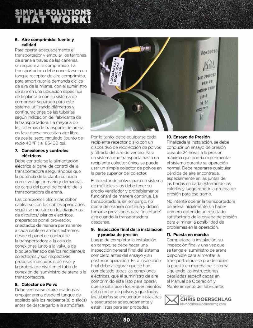
6. Aire comprimido: fuente y calidad Para operar adecuadamente el transportador y empujar los terrones de arena a través de las cañerías, se requiere aire comprimido. La transportadora debe conectarse a un tanque receptor de aire comprimido, para amortiguar la demanda cíclica de aire de la misma, con el suministro de aire en una ubicación específica de la planta o con su sistema de compresor separado para este sistema, utilizando diámetros y configuraciones de las tuberías según indicación del fabricante de la transportadora. La mayoría de los sistemas de transporte de arena en fase densa necesitan aire libre de aceite, seco, regulado (punto de rocío 40 ºF ) a 85-100 psi.
7. Conexiones y controles eléctricos Debe controlarse la alimentación eléctrica al panel de control de la transportadora asegurándose que la potencia de la planta coincida con el voltaje primario y demandas de carga del panel de control de la transportadora de arena.
Las conexiones eléctricas deben cablearse con los cables apropiados, según se muestre en los diagramas de circuitos/ planos electricos, preparados por el proveedor, cnectados de manera permanente a cada cable en ambos extremos, desde el panel de control de la transportadora a la caja de conexiones junto a la válvula de bloqueo/llenado del/los recipiente/s colector/es y sus respectivas probetas indicadoras de nivel y la probeta de nivel en el tubo de conexión del suministro de arena a la transportadora.
8. Colector de Polvo Debe ventearse el aire usado para empujar arena desde el tanque de soplado al/a los recipiente(s) o silo(s) antes de descargarlo a la atmósfera.
Por lo tanto, debe equiparse cada recipiente receptor o silo con un dispositivo de recolección de polvos y filtrado del aire de venteo. Para un sistema que transporta hasta un recipiente colector único, se puede usar un simple colector de polvos en la parte superior del colector.
El colector de polvos para un sistema de múltiples silos debe tener su propio ventilador y probablemente funcionará de manera continua. La transportadora, sin embargo, no opera de manera continua y deben tomarse previsiones para "insertarle" aire cuando la transportadora descanse.
9. Inspección final de la instalación y prueba de presión Luego de completar la instalación en campo, se debe hacer una inspección general final del sistema completo antes del ensayo y su posterior operación. Esta inspección final debe asegurar que se han completado todas las conexiones eléctricas, que el suministro de aire comprimido está listo para operar, que se satisfacen los requerimientos del colector de polvos y que todas las tuberías se encuentran instaladas y aseguradas adecuadamente y están listas para ser probadas.
10. Ensayo de Presión Finalizada la instalación, se debe conducir un ensayo de presión durante 24 horas a la presión máxima que podría experimentar el sistema durante su operación normal. Debe repararse cualquier pérdida de aire encontrada, especialmente en las juntas de las bridas en cada extremo de las calerías y luego repetir la prueba de presión para ese tramo.
No intente operar la transportadora de arena inicialmente sin haber primero obtenido un resultado satisfactorio de la prueba de presión para eliminar la posibilidad de problemas en la operación.
11. Puesta en marcha Completada la instalación, su inspección final y una vez que se tenga el suministro de arena disponible para alimentar la transportadora, se puede iniciar la puesta en marcha del sistema siguiendo las instrucciones detalladas especificadas en el Manual de Operación y Mantenimiento del fabricante.
80
Contact: CHRIS [email protected]