guidelines for the flexible installation of … · permeapave/rio permeapave permeable concrete...
TRANSCRIPT

Permeapave/Rio Permeapave Permeable Concrete Block Paving
INSTALLATION GUIDE
11/2012

2 | P a g e
INSTALLATION OF PERMEAPAVE DRAINAGE SYSTEMS DOMESTIC APPLICATION ONLY Scope These guidelines are in accordance with BS 7533-13 : 2009 : Guide for the design of permeable pavements constructed with concrete paving blocks and flags, natural stone slabs and setts and clay pavers. Health and Safety Information Safe working practices should be employed at all times during the construction process and all necessary Personal Protective Equipment (PPE) should be worn. Check for services and contact the service provider for advice if gas or electric services run through the intended Permeapave site. Care must be taken when constructing over sewer, rainwater & water pipes to ensure that the services remain supported for their full length by undisturbed material and are surrounded on the remaining sides by a minimum of 150mm of 6mm material. Aggregates required 1 cubic metre equals 1.75 tonnes Sqm drive 10 20 30 40 50 60 70 80 90 100 20mm tonne 3.5 7 10.5 14 17.5 21 24.5 28 31.5 35 6mm tonne 0.9 1.8 2.6 3.5 4.4 5.3 6.1 14.4 15.3 16.2
Permeapave must be laid with a 20mm and 6mm washed graded angular aggregate
The aggregate is available from Hanson Group direct on a dedicated phone line 0845 451 0797
Telephones are open Mon-Fri 8am to 5pm and Sat 8am to 12pm
Payment is by pro-forma invoice, credit card or cheque
72 hours lead time
Available in tipper loads or in tonne bags. Tonne bags are available for small order quantities or where access is difficult
Pavement design For most domestic applications a sub-base of 150mm of 20mm clean crushed stone with well defined edges should prove to be sufficient. However the paving design must be based upon the prevalent ground conditions and type and frequency of anticipated loads. Sub-base Grading details Sieve size (mm) % by mass passing sieve 31.5 98 to 100
20 90 to 99 14 10 25 to 70 6.3 4 0 to 15 3.15 2.8 0 to 5 2
3 | P a g e
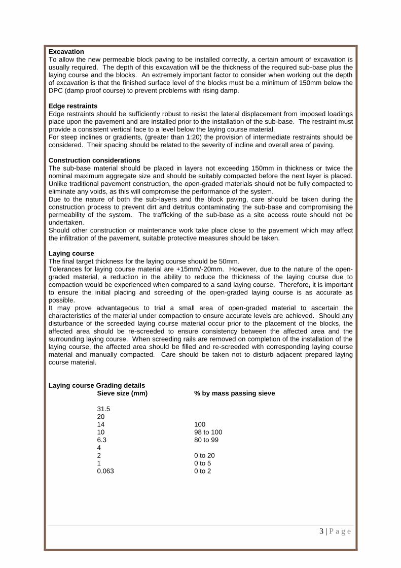
Excavation To allow the new permeable block paving to be installed correctly, a certain amount of excavation is usually required. The depth of this excavation will be the thickness of the required sub-base plus the laying course and the blocks. An extremely important factor to consider when working out the depth of excavation is that the finished surface level of the blocks must be a minimum of 150mm below the DPC (damp proof course) to prevent problems with rising damp. Edge restraints Edge restraints should be sufficiently robust to resist the lateral displacement from imposed loadings place upon the pavement and are installed prior to the installation of the sub-base. The restraint must provide a consistent vertical face to a level below the laying course material. For steep inclines or gradients, (greater than 1:20) the provision of intermediate restraints should be considered. Their spacing should be related to the severity of incline and overall area of paving. Construction considerations The sub-base material should be placed in layers not exceeding 150mm in thickness or twice the nominal maximum aggregate size and should be suitably compacted before the next layer is placed. Unlike traditional pavement construction, the open-graded materials should not be fully compacted to eliminate any voids, as this will compromise the performance of the system. Due to the nature of both the sub-layers and the block paving, care should be taken during the construction process to prevent dirt and detritus contaminating the sub-base and compromising the permeability of the system. The trafficking of the sub-base as a site access route should not be undertaken. Should other construction or maintenance work take place close to the pavement which may affect the infiltration of the pavement, suitable protective measures should be taken. Laying course The final target thickness for the laying course should be 50mm. Tolerances for laying course material are +15mm/-20mm. However, due to the nature of the open-graded material, a reduction in the ability to reduce the thickness of the laying course due to compaction would be experienced when compared to a sand laying course. Therefore, it is important to ensure the initial placing and screeding of the open-graded laying course is as accurate as possible. It may prove advantageous to trial a small area of open-graded material to ascertain the characteristics of the material under compaction to ensure accurate levels are achieved. Should any disturbance of the screeded laying course material occur prior to the placement of the blocks, the affected area should be re-screeded to ensure consistency between the affected area and the surrounding laying course. When screeding rails are removed on completion of the installation of the laying course, the affected area should be filled and re-screeded with corresponding laying course material and manually compacted. Care should be taken not to disturb adjacent prepared laying course material. Laying course Grading details Sieve size (mm) % by mass passing sieve 31.5
20 14 100 10 98 to 100 6.3 80 to 99 4 2 0 to 20 1 0 to 5 0.063 0 to 2

4 | P a g e
Baffles Baffles are intermediate concrete barriers used on sloping sites to prevent water flowing to the bottom of the slope and collecting there and subsequently coming out of the joints between the blocks.
Length across fall
Gradient
1 in 500 1 in 250 1 in 100 1 in 50 1 in 25 1 in 10
5 0 0 0 0 0 2
10 0 0 0 0 1 4
20 0 0 0 1 3 9
30 0 0 1 2 5 14
40 0 0 1 3 7 19
Wearing course Laying Paving units should be installed on the laying course material so that the final level is within the permitted surface tolerance. String lines should be utilised as often as required. This is necessary to ensure the bond pattern is maintained and straight lines are achieved in the finished paving. The manufacturing tolerances of the paving units, profile of the site and frequency of string lines should be taken into consideration during installation. Paving units should be laid such that the joint profile interlocks with its neighbouring units. Joint widths may be varied slightly in order to achieve straight lines or maintain bond. When laying block paving, the blocks should be mixed simultaneously from a minimum of 3 packs, taking vertically from each slice offered by the pack. This is necessary to ensure an even distribution of both the colours and any manufacturing tolerances offered by the blocks. Lay whole units first, followed by cut units around obstacles or at edges. No paving unit should be cut down to less than one quarter of its original size to prevent looseness or dislodgement at a later date. Where it appears that only a small section of block will fit, the “inboard cutting” technique should be adopted. The use of a larger or full unit against the edge restraint, allows a small unit to be placed in the resulting space. Where slopes, gradients or ramps are being constructed, placement of the paving units should commence at the lowest point ie: the bottom of the slope, working upwards. Where there is a risk of lateral movement of the paving units due to the gradient encountered, the provision of additional intermediate restraint should be considered. Compaction Compaction should be undertaken with a plate vibrator. Prior to final compaction of the surface, joints should be filled with the same grading of material as that used for the laying course. All joints should remain full of jointing material at all times, with periodic checking and replacing carried out where necessary. General The bond pattern should be suited to the application and likely use of the paving. Areas which receive frequent vehicle turning, accelerating or decelerating should be laid in a herringbone pattern. Stretcher bond may be used successfully in very lightly trafficked areas, providing the direction of the traffic is perpendicular to the laying pattern and the paving is not subjected to the above movements. Basket weave patterns should not be used in areas receiving vehicular traffic. Cutting Cutting may be carried out using a diamond tipped power saw, a block-splitting guillotine, or hammer and bolster. It must however be noted that the aesthetic finish achieved will depend greatly upon the choice of cutting mechanism and the skill of the installer. Cut blocks should be inserted prior to completion of the working period to prevent any movement of unrestrained blocks. Blocks should be cut such that the resultant joint width remains within the 2-6mm tolerance. When laying to tight curves it may not be always possible to maintain a maximum 6mm joint, in which case, cut or special shaped units may have to be considered.

5 | P a g e
Maintenance In brief, Stonemarket would recommend:
Inspect at least twice a year, spring and autumn, and/or after a major storm
Brush the surface to remove debris and encrusted sediment
Maintain the area to be free of vegetation
Replenish the joints when empty
Ensure that the owner is aware of the pavement construction and the “do’s and don’ts” of the system
Further Information For technical advice on commercial installation, or when confronted by unusual problems or circumstances, please contact Stonemarket Technical Advisory Services on 0870 411 2233, or by email on [email protected] CONDITIONS AND GUIDELINES Definition of scope In some parts of the country there are ground conditions where infiltration could adversely affect foundations to houses, therefore, if in doubt seek advice from a specialist or the local authority building control department. Domestic Permeapave is only intended for domestic driveways, paths and patios which are subject to foot traffic or over-run by typical domestic vehicles that do not exceed a gross vehicle weight of 3.5 tonnes, although occasional use by heavier delivery vehicles should not have a detrimental effect. The domestic Permeapave system is only intended for driveways or path where infiltration only is required in which the area must drain itself only and no other surrounding paved or roofed areas. Properties constructed pre-1920’s may not have been built on a concrete foundation; therefore, if this is proved to be correct, then the Stonemarket domestic Permeapave system should not be installed. Soil strength Stonemarket’ domestic Permeapave system must be either installed on a sub-grade which has previously had an established existing driveway* or on an area which has sub-grade soil strength greater than 5% Laying onto a sub-grade which has previously taken an established driveway proves that the sub-grade was able to take the driveway construction. The standard designs are based on conditions where the sub-grade is greater than 5%, therefore, this is mirrored in our advice

6 | P a g e
Rock or Soil Simple field test CBR Type Condition Rock Hard Requires mechanical pick for Above 5%
excavation Sand Compact 50mm square peg hard to drive in > 5% Gravel 50mm Clay Sandy Stiff Cannot be moulded by fingers 5% - 2% Sandy Clay Need pick for excavation Clay Firm Can be moulded by fingers 5% - 2% Sandy Clay Need spade for excavation Sand Loose Dry lumps easily broken down 2% Silty Clay 50mm square peg driven in easily Clayey Sand Silt Soft Can be easily moulded by fingers <2% Sandy Clay Silty Clay Clay Silt Very soft Exudes between fingers when seek advice Sandy Clay squeezed Silty Clay Clay The CBR of the rock or soil is significantly affected by moisture Soil permeability The domestic Permeapave system is only suitable for soil areas where infiltration applies and the test criteria have been met according to the standard permeability test. For the standard permeability test, a test hole should be dug for every 20m
2 of driveway. There should be a minimum of two holes.
Holes/pits should be spaced evenly in relation to the proposed Permeapave area. The soil test is the key. If the sub-grade soil is not permeable then domestic Permeapave cannot be installed. Surface gradient
The intended Permeapave area must fall away from the property. The top surface of the driveway should finish at least 150mm below any adjoining DPC level.
The area should also fall away from all properties and buildings.
If the intended Permeapave system falls to the house, then depending on the gradient, water could discharge and pool in and around areas of the house structure. This could lead to damp areas appearing on the masonry leaf.
If the driveway exceeds 20m in length and has a gradient greater than 1 in 100, then please contact the Technical Advisory Services Department for assistance.
Depending on the gradient in relation to the length, additional construction processes will be required by the provision of baffles.
Discharge onto roadway The domestic Permeapave area must not discharge onto surrounding public roadways and pathways or towards any buildings

7 | P a g e
Existing foundations If the property lies adjacent to or is less then 600mm from the proposed domestic Permeapave driveway area, establish the depth of the house foundation before undertaking any soil test or Permeapave installation. The house foundation top surface must be a minimum of 600mm below the finished level of the Permeapave surface. The foundations area must not be disturbed as the integrity of the building may be affected over time. The level of water discharge must be above the level of the foundations to avoid instability at foundation level. Rainwater catchment area (Driveway area) No adjoining surfaces areas (rainwater pipes, roof areas etc) must drain onto and into the Permeapave driveway area. However, small areas, such as door steps and garage areas, are acceptable providing that they don not exceed 5% of the driveway area. If other areas are drained in addition to the driveway area then the hydraulic calculation will dictate the depth, thus increasing the 200mm depth for the 20mm open graded material. Trees When installing close to existing trees, tree roots smaller than 25mm diameter may be pruned back, preferably to a side branch, using a suitable pair of secateurs or hand saw. Roots larger than 25mm should only be severed following consultation with an arboriculturist, as they may be essential to the tree’s health and stability. Protection of the pavement will also be required, hence the requirement of a permeable root barrier system, such as the Geoweb bio-barrier system (Fiberweb) or similar, which is non-surface protruding, so does not present a trip hazard once installed. Integrity of the pavement installation and intended life may be affected by the ingress of roots. SOIL PERMEABILITY – based on the BRE Digest 365 test procedure
Remove topsoil/paving material to exposed sub-grade soil
Dig hole within sub-grade soil to the size shown in Fig 1, ensure that all sides and the bottom surface of the hole are trimmed and levelled accordingly
Fig 1
Fill hole with water and allow to drain away naturally. Repeat this process 3 times. If the water does not drain away at all then the sub-grade soil does not have adequate permeability properties
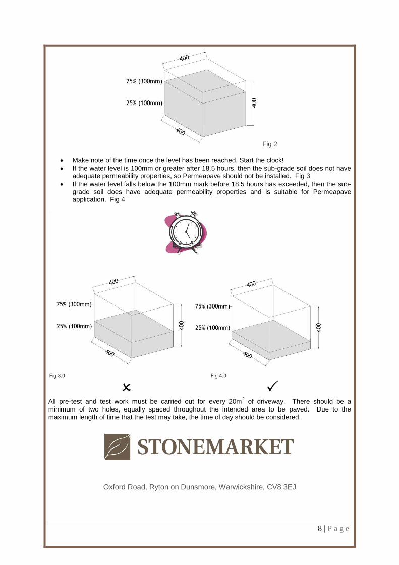
Fill the hole with water to 75% (300mm) of the excavated height shown in Fig 2
8 | P a g e
Fig 2
Make note of the time once the level has been reached. Start the clock!
If the water level is 100mm or greater after 18.5 hours, then the sub-grade soil does not have adequate permeability properties, so Permeapave should not be installed. Fig 3
If the water level falls below the 100mm mark before 18.5 hours has exceeded, then the sub-grade soil does have adequate permeability properties and is suitable for Permeapave application. Fig 4
All pre-test and test work must be carried out for every 20m2 of driveway. There should be a
minimum of two holes, equally spaced throughout the intended area to be paved. Due to the maximum length of time that the test may take, the time of day should be considered.
Oxford Road, Ryton on Dunsmore, Warwickshire, CV8 3EJ

9 | P a g e
PERMEAPAVE ON SLOPING SITES

10 | P a g e
AGGREGATE INSTALLATION AROUND DRAINAGE PIPES

11 | P a g e
ROOT BARRIER

12 | P a g e
PERMEAPAVE LAYING PATTERN

13 | P a g e
PERMEAPAVE LAYING PATTERN

14 | P a g e
RIO PERMEAPAVE LAYING PATTERN