guidelines for the application of small-scale
TRANSCRIPT

Guidelines for the Application of Small-Scale, Decentralised Wastewater Treatment Systems
A Code of Practice for Decision Makers
December 2018
United Republic of Tanzania
Ministry of Water

1
December 2018
Guidelines for the Application of Small-Scale, Decentralised Wastewater Treatment Systems
A Code of Practice for Decision Makers

2
Foreword
Adequate investment in water supply, sanitation and hygiene (WASH) is critical to improving human development and reducing poverty. Improving WASH has been associated with improved life in child’s early years, which is critical for achievement in later life. Conversely, lack of WASH has been associated with interruption of healthy childhood development and stunting, which can adversely affect other facets of development at later life. Further, lack of adequate WASH facilities contributes to waterborne diseases. For example, it is estimated that, in 2017, some 4,985 cases of cholera were reported in Tanzania, mainly because of poor access to sanitation facilities (World Bank, 2018). Additionally, it has widely been argued that Sustainable Development Goal six (SGD 6) is inextricably linked with other SGDs and targets.
A recent World Bank report on water supply, sanitation and hygiene indicates that 40 percent of the population in Tanzania lack access to improved drinking water and 80 percent rely on rudimentary and unsafe sanitation facilities (World Bank, 2018). Concerted and urgent efforts are therefore needed to accelerate the achievement of the SDG targets on WASH.
Decentralised wastewater treatment systems (DEWATS) can provide an appropriate and timely solution for wastewater management and accelerate the achievement of SDG targets on WASH. DEWATS have proven to be an effective strategy for complementing the traditional centralised wastewater management system, which is inevitably costly and complex. DEWATS provides an alternative flexible, efficient and cost effective community based sanitation solution for managing domestic and industrial wastewater.

3F O R E W O R D
The present guidelines support the scaling up of wastewater treatment solutions that follow the DEWATS approach. These guidelines provide fundamental guidance to all steps of a DEWATS project (from planning and throughout implementation, including operation, maintenance, monitoring and evaluation), while emphasising the importance of all aspects of an enabling environment. These guidelines also explain all steps of the sanitation chain (from containment, conveyance and treatment, to reuse, disposal or discharge).
The guidelines are consistent with the Government of Tanzania standards and policy framework in water supply, sanitation and hygiene (WASH). The guidelines support the Government’s efforts to accelerate the achievement of national targets on WASH and those in SDG 6. It is our hope that various stakeholders, including communities and private sector, will use these guidelines in developing wastewater management programmes in their efforts to contribute to the achievement of water supply, sanitation and hygiene services for all.
Prof. Kitila MkumboPermanent SecretaryMinistry of Water

4
Faecal Sludge Treatment Plant, Wailes, Dar es SalaamFaecal Sludge Treatment Plant (designed by BORDA Tanzania, financed by UKAID) with biogas settler, ABR, Feeding tank and sub-surface water distribution system. The FSTP produces biogas for cooking purposes, and treated wastewater is used to irrigate the nearby banana plantation.

5F O R E W O R D
National Housing Corporation (NHC) Mwongozo Affordable Housing Development, Kigamboni, Dar es SalaamOn-site wastewater management system (designed by BORDA Tanzania) with septic tanks, simplified sewers, ABR, AF, PGF and sub-surface water distribution network.

6
Acknowledgements
The development of these guidelines was supported by the United Nations
Environmental Programme (UNEP), United Nations Human Settlements
Programme (UN-HABITAT) and the Bremen Overseas Research and Development
Association (BORDA) Tanzania. The guidelines were prepared by BORDA
Tanzania with substantial inputs gathered during regular stakeholder workshops
conducted between July 2016 and April 2018, and peer reviewed by esteemed
experts from the Tanzanian water, sanitation and hygiene (WASH) sector.
UNEP: Birguy Lamizana
UN-HABITAT: Tekalign Tsige
BORDA Team: Jutta Camargo, Laura Bright-Davies, Leonidas Deogratius
Bernado, Tim Fettback, Godlove Ngoda, Bjoern Pietruschka, Leandra Roller,
Modekai Sanga, Andreas Schmidt, Eva Schoell, Dennis Wolter.
BORDA wishes to acknowledge the support of the government ministries and
agencies that made the development of these guidelines possible: Ministry of
Water (MoW); Ministry of Health, Community Development, Gender, Elderly
and Children (MoHCDGEC); Ministry of Education and Vocational Training
(MoEVT); Tanzanian Bureau of Standards (TBS); and Dar es Salaam Water and
Sewerage Authority (DAWASA).
We would also like to thank the following individuals who contributed their
valuable time to the development of these guidelines, through attending
workshops, providing comments, and carrying out the peer review (in
alphabetical order):
Honest Anicetus (MoHCDGEC), Joseph Birago (MoHCDGEC), Blandina Cheche
(NEMC), Gratius Haule (RAS-DSM), Joerg Henkel (ACRA), Nasra Hussein (TBS),
Erick Jackson (DAWASCO), Nadhifa S. Kemikimba (MoW), Stephen Kiberiti
(MoHCDGEC), Frank Kibumo (TBS), Dr. Jacob Kihila (Ardhi University),
Dr. Richard Kimwaga (UDSM), Elizabeth Kingu (RAS-DSM), Jasper Kirango
(OSWAMS), Dialista Kirenga (MoW), Sanford Kombe (Arusha Biogas Contractors),
Theresia Kuiwite (MoEVT), Josephine S. Lemoyan (Singida MC), Martha
Kabuzya (ATAWAS), Genzabuke Madebo (EWURA), Hezron Magambo (CCI),
Mariam Mahamdu (MoHCDGEC), Mansour Mawlid Mandemla (MoW), Masoro
Masogo (Kigamboni MC), Dr. Shaaban Mgana (Ardhi University), Neli Msuya
(DAWASA), Mathias Mulagwanda (TAWASANET), Dorisia Mulashani (MoW),
Neema Mumghamba (MoW), Romanus Mwangingo (DAWASA), Juma M. Nassor
(OSWAMS), Simon Nchimbi (Kigamboni MC), Prof. Karoli Njau (NM-AIST), Marisa
Ruoss (TAWASANET), Hamadi R. Semdekwa (Ubungo MC), Nice Vahaye (Ubungo
MC).

7A C K N O W L E D G E M E N T S
ResourcesIn order to maintain consistency with existing and commonly referred to
sector literature, and to provide a comprehensive set of guidelines for the
most recommended technical solutions, content and diagrams within this
document have been extracted and adapted from several resources. These
are listed in the yellow boxes within the respective chapters. In particular,
we would like to highlight the following publications which provided
substantial content for the following chapters:
Chapter 4:
i Tilley, E., Ulrich, L., Christoph, L., Reymond, P., Schertenleib, R., &
Zurbrügg, C. (2014). Compendium of Sanitation Systems and Technologies.
IWA; EAWAG; WSSCC. (In particular pp. 74 – 165). Free PDF available at:
www.sandec.ch/compendium
i Gutterer, B., Sasse, L., Panzerbieter, T., & Reckerzügel, T. (2009).
Decentralised Wastewater Treatment Systems (DEWATS) and Sanitation in
Developing Countries. BORDA; WEDC. (In particular pp. 168 – 229)
Chapter 5:
i Lüthi, C., Morel, A., Tilley, E., & Ulrich, L. (2011). Community-Led Urban
Environmental Sanitation Planning (CLUES). Eawag-Sandec, WSSCC,
UN-HABITAT. Free PDF available at: www.sandec.ch/clues
i Strande, L., Ronteltap, M., & Brdjanovic, D. (Eds.) (2014). Faecal sludge
management: Systems approach for implementation and operation, Faecal
Sludge Management: Systems Approach for Implementation and Operation.
IWA. (In particular pp. 363 – 388). Free PDF available at: www.sandec.ch/
fsm_book
Relevant content was extracted from these resources, according to the
local Tanzanian context.
Readers are encouraged to refer to the original documents, to gain more
insight into potential options.

8

9A B B R E V I A T I O N S A N D A C R O N Y M S
List of Abbreviations & Acronyms
ABR Anaerobic Baffled Reactor
AF Anaerobic Filter
BOD Biochemical Oxygen Demand
BORDA Bremen Overseas Research and Development Association
CFU Colony Forming Unit
COD Chemical Oxygen Demand
CW Constructed Wetland
DEWATS Decentralised Wastewater Treatment Systems
FC Faecal Coliform
FSM Faecal Sludge Management
HRT Hydraulic Retention Time
LGA Local Government Authority
M&E Monitoring and Evaluation
O&M Operation and Maintenance
PGF Planted Gravel Filter
PPE Personal Protection Equipment
QMS Quality Management System
SoC Statement of Change
SS Settleable Solids
TSS Total Suspended Solids
UASB Up-flow Anaerobic Sludge Blanket Reactor

10 10
Table of Contents
Foreword — 2
Acknowledgements — 6
List of Abbreviations & Acronyms — 9
Table of Contents — 10
List of Tables — 12
List of Figures — 13
1 Introduction — 14
1.1 Background — 15
1.2 Rationale of the Guidelines — 15
1.3 Objective — 16
1.4 Scope of the Guidelines — 16

11T A B L E O F C O N T E N T S
2 Legal, Policy and Regulatory Framework — 18
2.1 Related Sectoral National Policies — 20
2.1.1 National Water Policy 2002 — 20
2.1.2 National Health Policy 2007 — 20
2.1.3 National Environmental Policy 1997 — 20
2.1.4 Community Development Policy 1996 — 20
2.2 Related National Legislations — 20
2.2.1 Water Supply and Sanitation Act No 12 (2009) — 20
2.2.2 Environmental Management Act, 2004 — 20
2.2.3 Public Health Act, 2009 — 21
2.2.4 Energy and Water Utilities Regulatory Authority (EWURA) Act, 2001 — 21
2.2.5 Water Resources Management Act (WARMA) 11/2009 — 21
2.2.6 Urban Planning Act 8/2007 — 21
2.3 Related National Strategies and Plans — 21
2.3.1 The National Environmental Health, Hygiene and Sanitation Strategy (NEHHSAS 2008-2017) — 21
2.3.2 National Water Sector Development Strategy 2006—2015 — 21
2.3.3 Water Sector Development Programme Phase II 2014—2019 — 21
2.4 Related National Guidelines — 21
3 Concepts Of Wastewater Management — 22
3.1 Definition of Decentralised Systems and Comparison to Centralised Systems — 23
3.2 Definition of On-Site and Off-Site Systems — 24
3.3 Definition of Small-Scale and Large-Scale Systems — 24
3.4 Faecal Sludge and Wastewater — 24
3.5 Sanitation System or Value Chain — 26
3.6 Enabling Environment — 27
3.7 Compliance with Effluent Standards — 28
3.7.1 Stepwise implementation — 29
3.7.2 Relationship between Treatment Performance, Effluent Standards and the Size of the Treatment Plant — 30
3.7.3 The Relationship between Characteristics of the Receiving Waterbody and Effluent Standards — 30
4 Components of Dewats — 32
4.1 Containment — 35
4.2 Conveyance — 35
4.2.1 Simplified Sewer — 35
4.2.2 Solids-free Sewer — 36
4.2.3 Conventional Gravity Sewer — 37
4.3 Treatment — 38
4.3.1 Preliminary Treatment — 39
4.3.2 Primary Treatment — 40
4.3.3 Secondary Treatment — 43
4.3.4 Advanced Secondary Treatment — 46
4.3.5 Treatment of Sludge from DEWATS — 50
4.4 Disposal/Reuse — 52
4.4.1 Treated Wastewater — 54
4.4.2 Treated Sludge — 58
4.4.3 Biogas — 59
4.5 DEWATS Module Combinations — 60
5 Phases of a DEWATS Project — 62
5.1 Planning and Design — 64
5.1.1 Launching of the planning process — 65
5.1.2 Feasibility Study — 65
5.1.3 Site and Technology Selection — 66
5.1.4 Flood Protection — 66
5.1.5 Detailed Project Development, Action Planning — 68
5.2 Implementation — 68
5.3 Handover and start-up — 68
5.4 Operation and Maintenance (O&M) — 69
5.4.1 Operation — 70
5.4.2 Maintenance — 72
5.5 Management — 74
5.5.1 Monitoring and Evaluation (M&E) — 74
5.5.2 Documentation and Recordkeeping — 75
5.5.3 Plant Security and Safety — 75
5.5.4 Asset Management — 76
5.5.5 Administrative Management — 77
6 References — 80
7 Appendix — 82

12
List of Tables Table 1 Characteristics of faecal sludge and wastewater 25
Table 2 Pros and cons of simplified sewers 35
Table 3 Pros and cons of solids-free sewers 36
Table 4 Pros and cons of conventional gravity sewers 37
Table 5 Wastewater treatment levels 38
Table 6 Pros and cons of preliminary treatment 39
Table 7 Pros and cons of septic tanks 41
Table 8 Pros and cons of settlers 41
Table 9 Pros and cons of biogas settler 42
Table 10 Pros and cons of an ABR 44
Table 11 Pros and cons of anaerobic filters 45
Table 12 Pros and cons of up-flow anaerobic sludge blanket reactors 46
Table 13 Pros and cons of horizontal subsurface flow constructed wetlands 47
Table 14 Pros and cons of vertical subsurface flow constructed wetlands 49
Table 15 Pros and cons of polishing/fish ponds 50
Table 16 Pros and cons of unplanted sludge drying beds 51
Table 17 Pros and cons of planted sludge drying beds 52
Table 18 Pros and cons of irrigation with treated wastewater 54
Table 19 Pros and cons of discharging treated wastewater using French Drains 55
Table 20 Pros and cons of soak pits 56
Table 21 Pros and cons of discharge of treated wastewater into surface waterbodies
57
Table 22 Pros and cons of the application of treated sludge in agriculture 58
Table 23 Pros and cons of biogas combustion 59
Table 24 Factors influencing the selection of the site (S) and the technologies (T) 67
Table 25 Operational tasks 71
Table 26 Regular inspection tasks 72
Table 27 Regular maintenance tasks 73
Table 28 Typical malfunctions of DEWATS and their causes 73
Table 29 Activity list for wastewater treatment projects 83

13L I S T O F T A B L E S & F I G U R E S
List of Figures Figure 1 Components of environmental sanitation 25
Figure 2 The value chain for decentralised wastewater management 26
Figure 3 Enabling environment for environmental sanitation planning 27
Figure 4 Concept of stepwise implementation 29
Figure 5 Components of the value chain following the DEWATS approach 34
Figure 6 Sketch of a simplified sewer 35
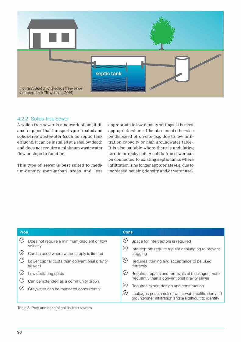
Figure 7 Sketch of a solids free-sewer 36
Figure 8 Sketch of a conventional gravity sewer 37
Figure 9 Flow diagram of a typical wastewater treatment system 38
Figure 10 Section view of a grease trap 39
Figure 11 Section view of a septic tank 41
Figure 12 Section view of a settler 41
Figure 13 Section view of a biogas settler 42
Figure 14 Section view of an ABR 43
Figure 15 Section view of an anaerobic filter (AF) 44
Figure 16 Section view of an up-flow anaerobic sludge blanket reactor (UASB) 45
Figure 17 Section view of a horizontal subsurface flow constructed wetland 47
Figure 18 Section view of a vertical subsurface flow constructed wetland 48
Figure 19 Section view of a vertical sand filter 49
Figure 20 Section view of a polishing/fish pond 50
Figure 21 Section view of an unplanted sludge drying bed 51
Figure 22 Section view of a planted sludge drying bed 52
Figure 23 Sketch of a drip irrigation system with treated wastewater 54
Figure 24 Sketch of a leach field 55
Figure 25 Section view of a soak pit 56
Figure 26 Sketch of treated water discharge into a waterbody 57
Figure 27 Application of treated sludge in agriculture 58
Figure 28 Examples of biogas appliances 59
Figure 29 General overview of the DEWATS implementation and operation process 63

1 Introduction
15I N T R O D U C T I O N
1.1 BackgroundSustainable Development Goal (SDG) 6.3.
aims at “halving the proportion of untreated
wastewater and substantially increasing re-
cycling and safe reuse globally” by 2030. This
goal is a continuation of SDG 6.2 to “achieve
access to adequate and equitable sanitation
and hygiene for all” by 2030. To achieve
these goals, sustainable and context-specific
wastewater treatment systems are urgently
needed.
In Sub-Saharan Africa, only three countries
achieved Millennium Development Goal
(MDG) target 7.C for sanitation, compared to
18 countries which met MDG target 7.C for
water supply1. The 2016 Demographic and
Health Survey estimates that 55% of Tan-
zania’s population lack access to improved
sanitation. Furthermore, the survey estimates
that only 23% of excreta is managed safely,
meaning that 42 million people lack adequate
treatment and disposal of their wastewater
and excreta2. In Tanzania’s most populous
urban areas such as Dar es Salaam and
Mwanza, the percentage of safely managed
wastewater and excreta is estimated to be
5-7 %3. This leads to contamination of drinking
water resources, and further challenges and
costs relating to the provision of safe drinking
water. Additionally, the increased supply of
drinking water in urban areas results in the
increased generation of wastewater, which
needs to be properly managed and treated.
Thus, any expansions of water-supply net-
works need to be considered hand-in-hand
with the improvement of wastewater and
excreta management.
The situation of the growing urban poor
population poses additional challenges. In
the urban areas where they live, sewerage
infrastructure development cannot keep pace
with rapid population growth, and treatment
sites for wastewater are scarce. The sanita-
tion situation in African cities is becoming
increasingly critical, as the urban population
increases rapidly (an 84% increase from 199
million people in 2000 to 366 million people
in 2015). This growth takes place mainly in
informal settlements with practically no prior
1 (The World Bank, 2017)
2 (The DHS Program, 2016)
3 (Brandes, 2015)
planning, and very limited infrastructure and
service provision4. The population of Dar es
Salaam (which houses almost 10% of Tanza-
nia’s inhabitants) is expected to more than
double by 2030, resulting in huge challenges
for practitioners in wastewater and excreta
management5.
It is becoming increasingly apparent that cen-
tralised and large-scale wastewater treatment
approaches cannot adequately address the
sanitation needs of the underserved pop-
ulation in Tanzania – particularly in cities
and emerging towns – which is why solutions
for urban wastewater management should
consist of a combination of centralised and
decentralised treatment systems. This is
due to the low coverage of centralised sewer
networks, huge capital investment require-
ments for centralised treatment plants and
the rapid growth of unplanned settlements.
In addition, in low-income countries where
sewers and centralised wastewater treatment
plants have been constructed, they have most
frequently resulted in failures6. On the other
hand, decentralised systems have proven in
many applications worldwide to be highly
effective in responding to the environmental
and sanitation challenges of rapidly growing
towns and cities.
1.2 Rationale of the GuidelinesIn Tanzania there are currently no guide-
lines or standards explicitly for small-scale
wastewater treatment systems and the reuse
or disposal of the by-products from the
treatment process. This document provides
guidance on the holistic approach need-
ed to implement and scale up small-scale
wastewater treatment systems and should
serve as the basis for the development of
Tanzanian standards for Decentralised
Wastewater Treatment Systems (DEWATS).
DEWATS offer a sustainable approach for
wastewater treatment systems, utilising
small-scale treatment plants. These solutions
have been developed and tested worldwide
in primarily low-income countries, and they
provide viable options for the improvement of
public health and environmental protection,
4 (AMCOW, et al., 2008)
5 (UN-HABITAT, 2014)
6 (Strande, et al., 2014)
16
with the additional benefits of resource reuse
(e.g. biogas, biosolids and irrigation water).
In 2017, more than 3,000 DEWATS had been
implemented worldwide, serving more than
970,000 people by treating 57,000m3 of
wastewater daily.
While these guidelines focus on DEWATS
for Tanzania, this does not imply that the
DEWATS approach is the only existing solution
for small-scale wastewater treatment. In the
future, the feasibility of other small-scale
solutions might be increased if reliable en-
ergy supply, high capacity for implementation
and operation, and other components of the
enabling environment become available.
In Tanzania more than thirty operational
DEWATS already exist, but as they are still
a relatively unknown option, further efforts
are required to capacitate the sector in
small-scale wastewater treatment. This shall
eventually lead to the mainstreaming and scal-
ing-up of these systems in Tanzania. In 2017,
BORDA assessed twenty Tanzanian small-scale
wastewater treatment systems. The results
from the Monitoring and Evaluation (M&E)
were used as a baseline for these guidelines
and the main findings are included here.
1.3 ObjectiveThese guidelines aim to complement the
existing regulatory framework on sanitation
in Tanzania, in order to foster an enabling en-
vironment for scaling up small-scale DEWATS
systems through effective dissemination,
regulation and law enforcement.
This document intends to provide guidance
on best practices for DEWATS in Tanzania
regarding all phases of a DEWATS project:
i Planning and design
i Implementation
i Handover and start-up
i Operation and Maintenance (O&M)
i Management (including M&E)
The guidelines were developed for relevant
stakeholders such as ministries and local
authorities, regulators, professional boards,
urban planners, housing developers, public
utilities, service providers, construction and
consulting companies, and other private sec-
tor implementers.
1.4 Scope of the GuidelinesThese guidelines are applicable to all activities
related to the planning, design, implementa-
tion, O&M, and M&E of small-scale municipal
wastewater treatment systems in Tanzania
that apply the DEWATS approach. Within this
document, small-scale systems are defined as
single systems with a treatment capacity that
ranges between 1 - 500 m³/day, and municipal
wastewater (or effluent) is defined as a mix
of domestic black- and greywater generated
by residential households, apartments, in-
stitutions (e.g. schools, hospitals), and small/
medium enterprises (e.g. hotels, restaurants).
Industrial non-organic effluents from manu-
facturing or chemical processes, as well as
stormwater, are excluded from these guide-
lines. The selected systems and technologies
cover all parts of the sanitation value chain
after the point of wastewater generation at
the user interface:
i Containment
i Conveyance
i Treatment
i Reuse and/or Disposal
This document does not provide guidance on the management of faecal sludge or
septage. For more information on FSM, please refer to the following publication:
Strande, L., Ronteltap, M., & Brdjanovic, D. (Eds.) (2014). Faecal sludge management:
Systems approach for implementation and operation. IWA.

17I N T R O D U C T I O N
National Housing Corporation (NHC) Mwongozo Affordable Housing Development, Kigamboni, Dar es SalaamOn-site wastewater management system (designed by BORDA Tanzania) with septic tanks, simplified sewers, ABR, AF, PGF and sub-surface water distribution network.

2 Legal, Policy and Regulatory Framework

19L E G A L , P O L I C Y A N D R E G U L A T O R Y F R A M E W O R K
The Analysis of Policies, Strategies and Regulatory Frameworks for Urban Sanitation
in Tanzania conducted by GIZ for Tanzania’s Ministry of Water
in 2017 provides a detailed description and analysis of the current Tanzanian urban
sanitation frameworks. The following is extracted from this analysis
(United Republic of Tanzania - MoW; GIZ, 2017).
Government Notice 2016 (GN 144/2016) on discharge of ministerial functions that was
published on 22nd of April 2016 allocates ministerial responsibilities for sanitation as
follows:
1. Matters on water quality and pollution control, water sources protection, sew-
age and drainage development are vested in the Ministry of Water.
2. Matters on preventive and curative services are vested in the Ministry of
Health, Community Development, Gender, Elderly and Children.
3. Matters on regional and local government administration are vested in the Pres-
ident’s Office. Among the functions of the Regional Administration and Local
Government is coordination of urban services such as transport, water and
sanitation. The administration of LGAs falls under the mandate of this Ministry.
4. Matters on environmental protection and enforcement are vested in the Vice
President’s Office.
Once a settlement has been declared an urban township/town, a Water Supply and
Sanitation Authority (WSSA) is established by the Minister responsible for Water in
consultation with the Minister responsible for Local Government Authorities. All
existing waterworks, plants, equipment and other assets of the government or a local
government are, without any compensation of costs incurred, transferred to the
respective WSSA. This is provided by section 16(1) of the Water Supply and Sanitation
Act 2009.
The establishment of a utility in any given area does not relieve the LGAs of their
duties under the Public Health Act, 2009 and Environmental Management Act, 2004.
The power to monitor the performance of LGAs lies with the Minister responsible for
local government. Politically, LGAs are also accountable to the people through their
councillors.
The analysis concludes that adequate basic legal, policy and regulatory frameworks
for the provision of sanitation in urban Tanzania exist. The roles and responsibilities
of the key stakeholders are well outlined and compliment each other with shared but
differentiated responsibilities. However, challenges have arisen because there are
multiple agents involved in the provision of sanitation services but weak collaboration
both within and between different governmental departments leading to a lack of
coordination between service providers. The analysis concludes that there is no organ
responsible for central coordination in terms of planning, funding and enforcing
sanitation rules and requirements. Consequently, the delivery and quality of sanitation
services are inconsistent.
The analysis also concludes that rules seem unclear in terms of financial responsibili-
ties and investments for urban sanitation: the manner of consultation is not provided,
the basis of the amount to be recovered is not given, and who finally pays is not clear.
These matters need clarification but may not require an additional policy strategy.

20
The level of government support and the
legal and regulatory frameworks are funda-
mental parts of an enabling environment for
any development project. There are several
examples worldwide, which suggest that the
provision of adequate wastewater treatment
systems is very likely to fail in the absence
of well-developed legal, policy and regulatory
frameworks. For this reason, it is of great im-
portance for practitioners to know the existing
framework. For policy makers it is important
to continuously identify and close the existing
gaps within the framework.
2.1 Related Sectoral National Policies
2.1.1 National Water Policy 2002The National Water Policy (NAWAPO) recognis-
es that lack of safe water, poor hygiene and
inadequate sanitation are major causes of
sicknesses and deaths in Tanzania. Therefore,
the policy highlights the need to integrate
water supply, sanitation and hygiene. The pol-
icy emphasises that sufficient supply of water
and adequate means of sanitation are basic
human needs. One of the policy’s objectives
is “to create an enabling environment and
appropriate incentives for the delivery of
reliable, sustainable and affordable urban
water supply and sewerage services.”
2.1.2 National Health Policy 2007The first objective of this policy includes
reducing the burden of disease and infant
mortality, and increasing life expectancy
through, among other things, facilitating
environmental health and sanitation. The
policy also aims to promote awareness among
government employees and the community at
large that health problems can only be ade-
quately solved through multi-sectoral coop-
eration. The Ministry of Health will continue
to collaborate with other stakeholders with
the aim of achieving better environmental
health and sanitation, and will enforce the
safe management of solid and liquid waste
at each facility.
2.1.3 National Environmental Policy 1997
The aims of this policy include protecting
water sources and preventing environmental
pollution. One proposed way to achieve this
is to promote technologies for wastewater
treatment and recycling. Moreover, appropri-
ate user-charges that reflect the full value of
water resources shall be introduced.
2.1.4 Community Development Policy 1996
The first aim of the policy is to enable Tanza-
nian communities to build a better life though
self-reliance and the use of locally available
resources (this is also a fundamental principle
of decentralised wastewater management).
Tanzanians shall be enabled to join together
and increase their commitment to self-devel-
opment. One of the policy’s objectives is to
help to respond to and meet the basic needs
of communities, such as:
i Food and nutrition
i Health and sanitation
i Water and environmental sanitation
i Appropriate technology for domestic
energy use
The policy also aims to help guide efforts to
improve rural and urban environments.
2.2 Related National Legislations2.2.1 Water Supply and Sanitation Act
No 12 (2009)The act provides the legal framework for
water supply and sanitation. It outlines the
responsibilities of government authorities
involved in the water sector in both urban
and rural areas. It states the obligations of
water supply and sanitation authorities to
provide water supply and sanitation services,
and it indicates their functions, powers and
duties. It also assigns responsibility for the
provision of adequate and reliable urban water
supply and sanitation to urban water supply
and sanitation authorities (UWSAs).
2.2.2 Environmental Management Act, 2004
This act defines the main roles of the National
Environment Management Council (NEMC). It
recognises all citizens’ right to a clean, safe
and healthy environment. In this context, safe
wastewater management is critical for the
benefit of the public at large. The act prohibits
all projects with significant negative effect
on the environment. The act is enforced by
environmental impact assessments.

21
2.2.3 Public Health Act, 2009This act emphasises a number of issues that
are of public concern, including sanitation
and hygiene. The act prohibits discharge of
wastewater without following national stand-
ards and laws. It emphasises that all public
buildings are to be equipped with sufficient
sanitary facilities.
2.2.4 Energy and Water Utilities Regulatory Authority (EWURA) Act, 2001
The general function of EWURA is to regulate
the provision of water supply and sanitation
services by a water authority or other persons.
This includes the establishment of standards
related to equipment and tariffs chargeable
for the provision of water supply and sanita-
tion services.
2.2.5 Water Resources Management Act (WRMA) 11/2009
This act provides the institutional and legal
framework for the sustainable management
and development of water resources. Spe-
cifically, it outlines the principles for water
resources management, and prevention and
control of water pollution. The act prohibits
discharge of waste into any waterbody includ-
ing ground water without written permit. In
this regard, the legislation provides guidelines
and standards for the construction and main-
tenance of water resources structures, and
the issuance and operation of water permits
and registration of boreholes.
2.2.6 Urban Planning Act 8/2007The aims of this act are to provide for the
orderly and sustainable development of land
in urban areas, to preserve and improve amen-
ities, to provide for the grant of consent to
develop land and powers of control over the
use of land, and to provide for other related
matters. This includes improving the pro-
vision of infrastructure and social services
for the development of sustainable human
settlements.
2.3 Related National Strategies and Plans
2.3.1 The National Environmental Health, Hygiene and Sanitation Strategy (NEHHSAS 2008–2017)
This strategy’s overall goal is to improve the
status of environmental health in Tanzania by
focusing on providing equitable and affordable
environmental health, sanitation and hygiene
services to all Tanzanians. Wastewater man-
agement has been emphasised as a priority
area to be addressed.
2.3.2 National Water Sector Development Strategy 2006-2015
The strategy sets out a mechanism for imple-
menting the NAWAPO, which aims to achieve
sustainable development in the sector through
an “efficient use of water resources and ef-
forts to increase the availability of water and
sanitation services.”
2.3.3 Water Sector Development Programme Phase II 2014–2019
The Government of Tanzania through the
MoW is implementing the Water Sector De-
velopment Programme (WSDP) for the period
2006–2025.” WSDP II has five components: (i)
Water Resources Management; (ii) Rural Water
Supply; (iii) Urban Water Supply and Sewerage;
(iv) Sanitation and Hygiene; (v) Programme
Delivery Support”
2.4 Related National Guidelines: i National Sanitation Options and Construc-
tion Guidelines (2012)
i Guidelines for Construction of Improved
Toilets and Environmental Sanitation (2014)
i National Sanitation Campaign Implemen-
tation Guidelines (2014)
i Design Manual for Water Supply and
Wastewater Disposal (2007)
i Guidelines for Sustainable Management
of Wetlands (2014)
i Guidelines on Management of Liquid
Waste (2013)
i Guidelines for Water, Sanitation and Hy-
giene in Health Care Facilities (2017)
i Water and Wastewater Quality Monitoring
Guidelines for Water Utilities (2014)
L E G A L , P O L I C Y A N D R E G U L A T O R Y F R A M E W O R K

22
3 Concepts of Wastewater Management

23C O N C E P T S O F W A S T E W A T E R M A N A G M E N T
The high variability of local conditions in
urban environments means that there is no
one-size-fits-all solution for wastewater treat-
ment. In a holistic city sanitation planning
approach, a combination of centralised and
decentralised, small- and large-scale, and
on- and off-site wastewater treatment systems
may be necessary to meet the sanitation re-
quirements of urban dwellers. In Tanzania’s
two largest cities, Dar es Salaam and Mwanza,
90%7 and 95%8 of the respective populations
rely on on-site sanitation options such as pits
and septic tanks connected to soak-aways
or ponds. Due to rapid urbanisation, these
systems are fast approaching their limits in
terms of environmental impact and space lim-
itations. This highlights the need for efficient
Faecal Sludge Management (FSM) as well as
increased efforts to implement wastewater
treatment systems that reduce the production
of faecal sludge.
Due to the below-mentioned differences
between FSM and wastewater management,
different guidelines are needed for each
topic. While the present guidelines focus on
wastewater, this does not imply that guide-
lines for faecal sludge are not needed.
3.1 Definition of Decentralised Systems and Comparison to Centralised Systems
Decentralised wastewater management sys-
tems include all parts of a sanitation system.
In comparison to centralised systems, these
systems are located at or near the point of
wastewater generation. Decentralised sys-
tems can be characterised and differentiated
from centralised systems along the following
lines9:
i Volume: Decentralised systems treat
relatively small volumes of water (typically
1 - 1,000 m³/day)10.
i Sewer type: Centralised systems typically
use conventional gravity sewers, while decen-
tralised systems typically use small-diameter
gravity sewers, often employing intermediate
settlers for solid-free sewers.
7 (Brandes, 2015)
8 (COWI, 2016)
9 (Hamilton, et al., 2004)
10 In these guidelines, small-scale decentralised systems are defined as single systems with a treatment capacity that ranges between 1 - 500 m³/day (See 3.3 Definition of Small-Scale and Large-Scale Systems)
i Treatment technology: Centralised sys-
tems in low-income countries typically employ
land-intensive technologies like waste stabi-
lisation ponds, while decentralised systems
typically use compact biological treatment
modules with lower space requirements per
connected user.
i Relative scale: Centralised systems
are intended to serve entire communities
or substantial areas of large communities.
Decentralised systems serve only a portion
of a community.
i Qualification level of O&M workers: Cen-
tralised systems require many high-skilled
experts, whereas decentralised systems
require predominantly vocationally-trained
workers under the supervision of one qualified
DEWATS expert.
i Low overall impact of (temporary) failure
of an individual DEWATS: This is compared
to failure of a centralised system, which can
lead to major financial, environmental and
public health impacts.
In the following section, the main pros and
cons of decentralised systems are listed. Ad-
ditional arguments exist and should be taken
into consideration when deciding between
centralised and decentralised solutions.
Positive aspects of decentralised wastewater
treatment systems:
i Enabling step-wise implementation: As
the availability of financial resources for
system upgrades is often the limiting factor,
incremental improvement presents a more
pragmatic approach.
i Easier financial planning and lower fi-
nancial risk: There is less investment cost
per system, and the success of one system is
unconnected to the success of another. Thus
if one system fails, the financial loss is lower.
i Can operate with zero or minimal power:
There are technologies for decentralised
systems that can operate with minimum or
zero power consumption.
i Less capital and lower O&M costs for
the sewer system: The treatment plant in a
decentralised system is situated at or near
the point of wastewater generation. Therefore,
only short distances of sewer are needed,
and at less depth than conventional systems.
These systems do not require pump stations,
which reduces the implementation as well as

24
the O&M costs. Additionally, solids-free sewer
systems are frequently used in combination
with decentralised systems.
i Increased potential of resource reuse: In
decentralised systems, the quantity of treat-
ed wastewater is lower than in centralised
systems. In addition, the possibility for reuse
(e.g. gardening) is higher, because the treated
wastewater can be used at multiple locations,
homogeneously spread in the area.
i Low water requirements for waste trans-
portation: Shorter sewers can operate with
lower water requirements for flushing.
i Reducing the risk of system failure: Easy
financial planning and lower requirements
for O&M (in the case of DEWATS) compared
to centralised systems serve to reduce the
risk of system failure.
Negative aspects of decentralised wastewater
treatment systems:
i Diseconomy of scale of wastewater treat-
ment plants regarding capital and O&M costs:
The bigger the system, the lower the cost per
user.
i Flow variations and high peak flow factors
lead to increased investment costs per connec-
tion: The smaller the wastewater system, the
higher the fluctuation of wastewater flow and
concentration. This leads to higher costs for de-
centralised systems, because the components
of these systems need to be relatively large.
i High effort for monitoring a large num-
ber of systems: Due to the larger number of
individual systems, the effort for law enforce-
ment by effluent monitoring is increased.
Decentralised systems are particularly suit-
able for urban and peri-urban areas such as
informal settlements or new housing devel-
opments that are located far from central-
ised sewerage infrastructure. Decentralised
systems are also suitable in small-to-medium
size towns that do not have centralised infra-
structure in place and where the diseconomy
of scale for sewer infrastructure outweighs the
economy of scale for a centralised treatment
plant. However, economies of scale also apply
to decentralised systems (but with a lower
range of connections), where a reasonable
scale and population density is required to
reduce the total capital cost per connection.
3.2 Definition of On-Site and Off-Site Systems
An on-site system is a wastewater collection
and treatment system that is installed on a
demarked and specified piece of land owned
by a private person or entity. Hence, the land-
owner is fully responsible for this treatment
system. An off-site system is a wastewater
collection and treatment system installed
on public land. Hence, this is a publicly
owned and publicly and/or privately managed
wastewater treatment system. This is a central
point that influences the whole project cycle.
3.3 Definition of Small-Scale and Large-Scale Systems
Within these guidelines, a small-scale
wastewater treatment system refers to a plant
that treats up to 500m3 of wastewater per day.
The DEWATS approach is also applicable for
larger systems with a treatment capacity of up
to 1,000m3 per day. However, larger systems
require more detailed specifications, such as
on energy for pumping. Additionally, larger
systems are required to meet stringent efflu-
ent standards due to the increased volume of
wastewater and load of contaminants being
emitted from the system.
3.4 Faecal Sludge and WastewaterMany faecal sludge treatment technologies
are based on those developed for wastewater
treatment, but it is important to note that
these technologies cannot be directly trans-
ferred. Faecal sludge mainly consists of
excreta and thus its characteristics differ
from wastewater, which has a direct impact
on the efficiency of treatment mechanisms11.
In comparison to wastewater, faecal sludge
typically has a higher solid content and a
higher concentration of pollutants, pathogens
and inorganic pollutants. Besides this, faecal
sludge characteristics differ widely between
different on-site sanitation technologies and
system management types. The quantity and
characteristics of faecal sludge also depend
on the design and construction of the user
interface (toilet type), how the technology is
used, how the faecal sludge is collected, and
the frequency of collection. For example, the
characteristics of faecal sludge from a public
toilet are substantially different to sludge
11 (Spellman, 1997)

25C O N C E P T S O F W A S T E W A T E R M A N A G M E N T
Parameter
Faecal SludgeMunicipal wastewater(See definition in part 1.4)High Strength
(e.g. public toilet)Low Strength(e.g. private septic tank)
COD [mg/l] 20,000 to 50,000 < 15,000 500 to 2,000
BOD [mg/l] App. 7,600 840 to 2,600 300 to 500
COD/BOD [-] 5:1 10:1 2:1
NH4-N [mg/l] 2,000 to 5,000 < 1,000 30 to 70
TSS [mg/l] > 30,000 App. 7,000 200 to 700
Ptotal [mg/l] 450 150 9 to 63
Helm. Eggs [No./l] 20,000 to 60,000 App. 4,000 300 to 2,000
FC [CFU/100ml] 1052 1052 104 to 1052
Table 1: Characteristics of faecal sludge and wastewater (Strauss & Montangero, 2002; Strande, et al., 2014; ATV-DVWK-A 198, 2003)
Figure 1: Components of environmental sanitation
Stormwater managment
Solid waste managment
Water suply only so far as it impacts
other enviromental saniation services
Excreta & wastewater managment
incl. greywater & faecal sludge
Water suplyonly so far as it impacts
other enviromentalsaniation services
Excreta & wastewatermanagment
incl. greywater & faecal sludge
Solid wastemanagment
Stormwatermanagment
Environmental Sanitation
Cross-cuttingmeasures

26
from a private septic tank. The approximate
characteristics of faecal sludge (high strength
and low strength) and wastewater are listed in
Table 1. Due to the unique characteristics of
wastewater and faecal sludge, not only must
the management and treatment system be
adapted, but also discharge standards need
to differ.
Another fundamental difference between
wastewater management and FSM is the need
for physical emptying and transportation of
faecal sludge. Typically, a variety of service
providers with different technologies and
methods for faecal sludge emptying and
transportation can be found operating simul-
taneously in any given geographical region12.
The management of faecal sludge leads to a
high risk of exposure for service providers
to physical, chemical and biological hazards
during emptying, transport and discharge of
faecal sludge. This is due to the nature of the
tasks which are carried out without suitable
barriers to human contact with harmful sub-
stances in the faecal sludge.
Wastewater systems are favourable over faecal
sludge systems, as no wastewater infiltrates
the ground on-site. Furthermore, wastewater
treatment systems are preferable because
of their lower O&M costs as compared to
12 (Strande, et al., 2014)
faecal sludge systems. If the willingness to
pay for household sewer connections and
wastewater surcharges can be ensured,
wastewater treatment systems are the most
suitable option.
Wastewater and FSM should also be seen as
one part of environmental sanitation. Envi-
ronmental sanitation can be seen as a set
of activities to achieve a sanitary physical
environment. Environmental sanitation goes
one step further than the traditional notion
of “sanitation” which is limited to the imme-
diate aspects of human excreta and/or the
provision of toilets. This approach includes
excreta and wastewater management, solid
waste management, stormwater management
and partly also water supply.
3.5 Sanitation System or Value Chain
A sanitation system is a context-specific
series of technologies and services for the
management of human waste, i.e. for collec-
tion, containment, transport, transformation,
and utilization or disposal. A well planned and
designed small-scale wastewater treatment
system incorporates the concept of a value
chain, in which the resource (wastewater) is
stored (containment), transported (convey-
ance) and processed (treatment) to obtain a
product (e.g. treated water, biogas or biosol-
ids). This is illustrated in Figure 2.
Figure 2: The value chain for decentralised wastewater management
User Interface Containment Conveyance Treatment Reuse/disposal

27C O N C E P T S O F W A S T E W A T E R M A N A G M E N T
3.6 Enabling EnvironmentAn enabling environment is a set of interre-
lated conditions that empower development
actors to engage in development policies,
strategies and projects in a sustained and
effective manner. This includes political,
legal, institutional, financial and economic,
educational, technical and social aspects. An
enabling environment is important for the
success of any development investment; with-
out it, the resources committed to bringing
about change will be ineffective. The six key
elements of an enabling environment include:
1. The level of government support, in terms
of political support and favourable national
policies and strategies.
2. The legal and regulatory framework, with
appropriate standards and codes at national
and municipal levels.
3. The Institutional arrangements that ac-
cept and support the community-centred
approach used.
4. Effective skills and capacity ensuring
that all participants understand and accept
the concepts and planning tools.
5. The financial arrangements that facilitate
the mobilisation of funds for implementation
and O&M.
6. The socio-cultural acceptance, i.e.
matching service provision to the users’ per-
ceptions, preferences, and commitments to
both short-term and long-term participation.
Within these guidelines, it is important to
emphasise that the success of a small-scale
wastewater treatment system depends on a
vast array of variables which are not limited to
the technical implementation of the system. If
any of the named key elements of the enabling
environment is not sufficiently provided, a
small-scale wastewater treatment system is
very likely to fail.
EnablingEnvironment
Socio-CulturalAcceptance
GovermentSupport
Skils andCapacities
Legal Framework
FinancialAgreements
InstitutionalArrangements
Figure 3: Enabling environment for environmental sanitation planning (adapted from Lüthi, et al., 2011)

28
3.7 Compliance with Effluent Standards
Standards are essential for the monitoring of
wastewater treatment systems of different
scales, according to effluent discharge and
applicability for reuse.
In Tanzania the discharge of wastewater to
the environment is currently regulated by the
effluent standards TZS. 860:2006.
The planning processes and concepts for assessing and creating an enabling environment are
explained comprehensively in the CLUES guidelines. These help to assess and foster favoura-
ble conditions for environmental sanitation planning in challenging urban environments. Most
of the critical elements to support an enabling environment should be identified or become
evident during the planning process. Ideally these elements should be identified, at least in
broad terms, prior to starting the planning and consultative process, so that the entire process
does not start off with unrealistic expectations or misconceptions.
The CLUES guidelines can be found online:
www.sandec.ch/clues
Lüthi, C., Morel, A., Tilley, E., & Ulrich, L. (2011). Community-Led Urban Environmental Sanitation
Planning (CLUES). Eawag-Sandec, WSSCC, UN-HABITAT.
For further reading, please refer to the following publications. These publications are also the
main sources for the information provided in this chapter.
1. WHO. (2001). Water Quality: Guidelines, Standards and Health: Assessment of risk and
risk management for water-related infectious disease. IWA.
2. Allaoui, M., Schmitz, T., Campbell, D., & de la Porte, C. A. (2015). Good Practices for
Regulating Wastewater Treatment. UNEP, WaterLex.
3. Tayler, K., & Parkinson, J. (2003). Effective strategic planning for urban sanitation
services: fundamentals of good practice. GHK International.
4. von Sperling, M. (1999). Stepwise Implementation of Water Quality Standards. XXVII
Congresso Interamericano de Engenharia Sanitária e Ambiental. Associação Brasileira
de Engenharia Sanitária e Ambiental.
5. WHO. (2006). Guidelines for the safe use of wastewater, excreta and greywater. Volume
2: Wastewater use in agriculture. World Health Organization.
The guidelines on the following pages provide
recommendations for incremental, stepwise
implementation of standards to support
the enabling environment for small-scale
wastewater treatment systems, with a custom-
ised approach that takes into account context
specific situations and needs.

29C O N C E P T S O F W A S T E W A T E R M A N A G M E N T
3.7.1 Stepwise implementationThe concept of stepwise implementation
applies to both the technical implementa-
tion of wastewater treatment systems and
the implementation of national standards for
effluent quality. The concept is based on the
idea that small steps of improvement are more
feasible compared to a single large step, and
eventually these small steps will lead to the
same or an even higher level of improvement.
This is visualised in Figure 4.
The effects of a stepwise implementation are
listed and explained below:
i Polluters are more likely to afford gradual
investment for control measures: Polluters and/
or water authorities will find it much more
feasible to divide investments into different
steps, than to make a large and in many cases
unaffordable investment.
i The present value of construction costs is
reduced: The division of construction costs
into different stages leads to a lower present
value than a single large initial cost. This as-
pect is more relevant in countries where, due
to inflation, interest rates are high.
i The cost-benefit of the first stage is likely to
be more favourable than in the subsequent stages:
In the first stage, when environmental con-
ditions are poor, a large benefit is usually
achieved with a comparatively low cost. In the
subsequent stages, the size of the benefit is
not as substantial, but the associated costs
are high. The cost-benefit ratio is then less
favourable.
i Operators have more time and better
conditions to ascertain the particular water or
wastewater characteristics: The operation of
the system will involve monitoring, which will
enable operators to develop more special-
ised knowledge of the water or wastewater
characteristics. The design of the second or
subsequent stages will be based on actual
characteristics observed during monitoring,
and not on generic values taken from the
literature.
i There is the opportunity to optimise opera-
tion, without necessarily undergoing a physical
expansion: Experience in the operation of the
system will lead to a good understanding of
its behaviour. This will allow, in some cases,
the optimisation of the process (improvement
of efficiency or capacity) without necessar-
ily requiring the physical expansion of the
system. The first stage will be analogous to
a pilot plant.
i There is time and opportunity to implement, in
the second stage, new techniques or better-devel-
oped processes: The availability of new or more
efficient processes for water and wastewater
treatment is always increasing with time.
Process development is continuous and fast.
The second or subsequent steps can make
Existing situation»where we are now«
Desired situtaion»where we want to be«
One big jump– requires huge investment
Smaller stepsare achievable
Figure 4: Concept of stepwise implementation (adapted from Tayler & Parkinson, 2003)

30
use of better and/or cheaper technologies,
which would not be possible within a single
large step.
i The country has more time to develop its own
standards: As time passes, the experience in
operating the system and evaluating its pos-
itive and negative implications in terms of
water quality, health status and environmental
conditions will lead to the establishment of
standards that are truly appropriate for local
conditions.
i The country has more time and better condi-
tions to develop a suitable regulatory framework
and institutional capacity: Experience obtained
in the operation of the system and in setting
up the required infrastructure and institution-
al capacity for regulation and enforcement
will also improve progressively, as the system
expands in the second and subsequent stages.
3.7.2 Relationship between Treatment Performance, Effluent Standards and the Size of the Treatment Plant
The standards for effluent discharge should
also depend on the size of the treatment plant:
the smaller the treatment plant is, the less
stringent the effluent standards need to be.
Additionally, with smaller treatment plants,
the option of recycling or reusing treated
wastewater can be considered, instead of
discharging into waterbodies. In many coun-
tries worldwide, this principle is recognised
in effluent standards. There are two main
reasons for this:
1. Small treatment plants treat only low
volumes of wastewater, but the capacity of
the receiving waterbody to handle a specific
loading (see Equation 1) is constant. Thus, the
quality of the effluent treated in a large-scale
system must be higher, because the loading
should not exceed a critical value.
Load = concentration x volume Equation 1
2. The treatment performance of large-
scale systems can be higher than small-scale
systems, because of the economy of scale:
the larger a system, the lower the price for
each user. High investments and O&M costs
for advanced treatment are only financially
feasible if the system is large enough.
3.7.3 The Relationship between Characteristics of the Receiving Waterbody and Effluent Standards
Effluent standards need to be adapted accord-
ing to the quality, self-cleaning capacity and
function of the receiving waterbody. For exam-
ple, the discharge of effluent into waterbodies
used for freshwater supply or in conservation
areas – as well as the volume ratios between
the inflowing wastewater and the receiving
body – must be strongly regulated.

31C O N C E P T S O F W A S T E W A T E R M A N A G M E N T
International School of Tanganyika (IST) Staff Housing Complex, Upanga, Dar es Salaam (project managed by Architectural Pioneering Consultants - APC)On-site wastewater management system (designed by BORDA Tanzania) with biogas settler, and PGF. The system produces biogas for cooking purposes, and treated grey-water is recycled for flushing toilets and irrigation around the campus.

32
4 Components of DEWATS

33C O M P O N E N T S O F D E W A T S
The term Decentralised Wastewater Treat-
ment Systems (DEWATS) was developed by
an international network of organisations
and experts. In these guidelines, the term
DEWATS is applied in singular or plural form,
referring to a chosen specific technological
modular system, linked up with management
and operations, that is part of a whole-system
approach. This “systems approach” includes
a whole range of different integral elements,
and it is part of the value chain within sus-
tainable sanitation services, specifically
targeted at urban and peri-urban areas. This
approach incorporates lessons learned from
the limitations of conventional centralised
and decentralised wastewater treatment
systems, thereby helping to meet the rapidly
growing demand for small-scale wastewater
treatment solutions.
The modular technology is characterised by
the following:
i DEWATS encompasses an approach, not
just a technical hardware package. Besides
technical and engineering aspects, the spe-
cific local economic and social situations are
also taken into consideration.
i DEWATS provides treatment for
wastewater flows with close COD/BOD ratios
from 1m3 to 1000m3 per day and unit.
i DEWATS can treat wastewater from do-
mestic or industrial sources, and are suitable
to provide primary, secondary and advanced
secondary treatment for wastewater from
sanitation facilities, housing colonies, public
entities like hospitals, or from businesses,
especially those involved in food production
and processing.
i DEWATS can be an integral part of com-
prehensive wastewater and sanitation strat-
egies. The technological systems should be
perceived as being complementary to other
centralised and decentralised wastewater
treatment options.
i DEWATS can provide a renewable energy
source depending on the technical layout (e.g.
biogas supplies energy for cooking, lighting
or power generation).
i DEWATS is based on a set of design and
layout principles.
The technologies following the DEWATS ap-
proach have demonstrated effective treat-
ment performance in applications in different
parts of the world. To scale up DEWATS,
BORDA Africa conducts DEWATS trainings
with the objective of capacitating different
practitioners in the sector. The applicability
of BORDA DEWATS in Tanzania is fostered
by long-term worldwide experience with and
documentation of these systems. Supporting
material created in the course of BORDA DE-
WATS projects includes:
i A Quality Management System (QMS)
tool which stipulates the standards and pro-
cedures for implementing and operating a
DEWATS successfully
i Training packages (biogas curriculum,
QMS training, etc.)
i Design tools
i Manuals for operation, maintenance and
management
i Monitoring tools
The main benefits of DEWATS are:
i Public health is safeguarded: By protect-
ing drinking water sources, DEWATS treat-
ment options will reduce the pollution load
of groundwater and surface water sources.
i Time efficient: Less than 12 months are
required for planning and implementing
DEWATS.
i Sustainability through informed choice:
Communities choose the DEWATS system and
components they prefer.
i Professional design and workmanship:
Technical options are tested and subjected
to rigid quality control.
i Cost efficiency: The investment and O&M
costs are low.
i Reduced need for monitoring: Due to
low operation costs, the risk of reducing the
treatment to save money (e.g. by turning off
aerators in activated sludge processes) is
minimised.
i Strengthened capacities through train-
ing and capacity building: Stakeholders are
trained and assisted to plan, implement and
manage DEWATS independently or in co-man-
agement arrangements.
i Replication: Trained local facilitators
and urban planners ensure future DEWATS
replications and scaling up within the target
cities.
A selection of technologies suitable for the
Tanzanian context are listed below, con-
sidering each stage along the sanitation
value chain. Components are combined in

34
For further reading and detailed design information, please refer to the following
publications. These publications are also the main sources for the information provid-
ed in chapters 4–5.
1. Tilley, E., Ulrich, L., Christoph, L., Reymond, P., Schertenleib, R., & Zurbrügg,
C. (2014). Compendium of Sanitation Systems and Technologies. IWA; EAWAG;
WSSCC.
2. DEWATS and Sanitation in Developing Countries: A Practical Guide; BORDA;
2009
3. Gutterer, B., Sasse, L., Panzerbieter, T., & Reckerzügel, T. (2009). Decentralised
Wastewater Treatment Systems (DEWATS) and Sanitation in Developing Coun-
tries. BORDA; WEDC.
4. von Sperling, M., & de Lemos Chernicharo, C. A. (2005). Biological Wastewater
Treatment in Warm Climate Regions. IWA.
5. Reynaud, N. (2014). Operation of Decentralised Wastewater Treatment Systems
(DEWATS) under tropical field conditions.
6. Strande, L., Ronteltap, M., & Brdjanovic, D. (Eds.) (2014). Faecal sludge man-
agement: Systems approach for implementation and operation, Faecal Sludge
Management: Systems Approach for Implementation and Operation. IWA.
Figure 5: Components of the value chain following the DEWATS approach
Containment
– Septic Tank
Reuse / Disposal
– French Drain
– Soak Pit
– Sludge Drying Beds
Treatment
Preliminary Tretment Primary Treatment Secondary Tretment Advanced Secondary Treatment
– Grease Trap
– Screens
– Grit Chamber
– Septic Tank
– Settler
– Biogas settler
– Anaerobic Baffled Reactor (ABR)
– Anaerobic Filter (AF)
– Up-flow Anaerobic Sludge Blanket Reactor (UASB)
– Constructed Wetlands
– Polishing Ponds
Conveyance
– Simplified Sewer
– Solids-Free Sewer
– Conventional Gravity

35C O M P O N E N T S O F D E W A T S
accordance with the wastewater influent and
the required effluent quality. Sanitation appli-
ances (user interface) and components that
are solely related to FSM are not listed here,
as they are excluded from the scope of these
guidelines (see part 1.4 on page 13). These
guidelines do not contain specific design
considerations, but only brief descriptions,
and general pros and cons of the respective
modules and technologies.
4.1 ContainmentContainment technologies collect and store
wastewater at the user interface on-site. Con-
tainment technologies are usually applicable
for low-cost, non-sewered sanitation (faecal
sludge) systems as intermediate storage, but
can also serve as pre-treatment modules for
small-scale wastewater treatment systems.
The main containment technology applicable
for wastewater treatment technologies is the
septic tank. In the vast majority of situations,
containment systems are already installed
on-site but are often improperly designed,
constructed and maintained, which poses se-
vere environmental hazards. Apart from septic
tanks providing some degree of pre-treatment,
the effluent usually contains high concentra-
tions of pollutants, which can carry severe
Pros Cons
Makes wastewater transport to the treatment plant more efficient
Costs can be offset with access permits
Lower costs for construction and O&M due to less depth and no pumping.
Requires expert design and construction
Can lead to odours if not properly maintained
public health and environmental burdens,
especially in densely populated urban areas
and in the vicinity of drinking water sources.
Hence, proper sealing of containment options
is crucial for environmental sanitation. Con-
tainment systems can also be implemented
to buffer peak flows.
4.2 Conveyance Technologies presented in this section are
sewer-based technologies, using water from
waterborne toilets as a conveying medium.
4.2.1 Simplified SewerA simplified sewer describes a sewerage
network that is constructed using smaller
diameter pipes laid at a shallower depth and
at a flatter gradient than conventional sewers.
This sewer system generally does not apply
pumping. For these reasons, simplified sewers
allow for a more flexible design at lower costs.
Simplified sewers can be installed in almost
all types of settlements and are especially
appropriate for dense urban areas where
space for on-site technologies is limited. They
should be considered as an option where there
is a sufficient population density (about 150
inhabitants per hectare) and a reliable water
supply (at least 60 L/capita/day).
Table 2: Pros and cons of simplified sewers
Figure 6: Sketch of a simplified sewer (adapted from Tilley, et al.,2014)
36
4.2.2 Solids-free SewerA solids-free sewer is a network of small-di-
ameter pipes that transports pre-treated and
solids-free wastewater (such as septic tank
effluent). It can be installed at a shallow depth
and does not require a minimum wastewater
flow or slope to function.
This type of sewer is best suited to medi-
um-density (peri-)urban areas and less
septic tank
Figure 7: Sketch of a solids free-sewer (adapted from Tilley, et al., 2014)
Pros Cons
Does not require a minimum gradient or flow velocity
Can be used where water supply is limited
Lower capital costs than conventional gravity sewers
Low operating costs
Can be extended as a community grows
Greywater can be managed concurrently
Space for interceptors is required
Interceptors require regular desludging to prevent clogging
Requires training and acceptance to be used correctly
Requires repairs and removals of blockages more frequently than a conventional gravity sewer
Requires expert design and construction
Leakages pose a risk of wastewater exfiltration and groundwater infiltration and are difficult to identify
Table 3: Pros and cons of solids-free sewers
appropriate in low-density settings. It is most
appropriate where effluents cannot otherwise
be disposed of on-site (e.g. due to low infil-
tration capacity or high groundwater table).
It is also suitable where there is undulating
terrain or rocky soil. A solids-free sewer can
be connected to existing septic tanks where
infiltration is no longer appropriate (e.g. due to
increased housing density and/or water use).
sewer main
manhole

37C O M P O N E N T S O F D E W A T S
4.2.3 Conventional Gravity SewerConventional gravity sewers are large net-
works of underground pipes that convey
blackwater, greywater and, in many cases,
stormwater from individual households to
a (semi-)centralised treatment facility using
gravity (and pumps when necessary).
Because they can be designed to carry large
volumes, conventional gravity sewers are
very appropriate to transport wastewater to
a (semi-) centralised treatment facility. Con-
struction of conventional sewer systems in
dense, urban areas is complicated because it
disrupts urban activities and traffic. Conven-
tional gravity sewers are expensive to build
and a professional management system must
be in place, as the installation of a sewer
line is disruptive and requires extensive co-
ordination between authorities, construction
companies and property owners.
Table 4: Pros and cons of conventional gravity sewers
Pros Cons
Less maintenance compared to simplified and solids-free sewers
Greywater and possibly stormwater can be managed concurrently
Can handle grit and other solids, as well as large volumes of flow
Very high capital costs
High O&M costs
A minimum velocity must be maintained to prevent the deposition of solids in the sewer
Requires deep excavations
Difficult and costly to extend as a community changes and grows
Requires expert design, construction and maintenance
Leakages pose a risk of wastewater exfiltration and groundwater infiltration and are difficult to identify
sewer main
manhole
Figure 8: Sketch of a conventional gravity sewer (adapted from Tilley, et al., 2014)

38
4.3 TreatmentTreatment technologies are classified ac-
cording to different levels depending on their
treatment objectives and removal efficiency
(see Figure 9 and Table 5). The following
section is divided into the below-mentioned
treatment levels.
As DEWATS make use of various natural bi-
ological and physical treatment processes
that require different boundary conditions to
function efficiently, DEWATS are comprised of
a series of treatment units, each providing an
ideal environment for the removal of certain
groups of pollutants.
Wastewater
PreliminaryTreatment
PrimaryTreatment
SecondaryTreatment
AdvancedSecondaryTreatment
Reuse/Disposal
SludgeTreatment
Figure 9: Flow diagram of a typical wastewater treatment system
Table 5: Wastewater treatment levels
Level Removal
Preliminary i Coarse solids (larger material and sand)
Primary i Settleable solids (SS)
i Particulate (suspended) BOD (associated to the organic matter component of
the SS)
Secondary i Particulate (suspended) BOD (associated to the particulate organic matter present
in the raw sewage, or to the non-settleable particulate organic matter, not removed
in the possibly existing primary treatment)
i Soluble BOD (associated to the organic matter in the form of dissolved solids)
To enable evidence-based decisions, it is also recommended to consult the results of
the 4S research project which conducted the first systematic assessment of small-scale
sanitation systems in South Asia. In this assessment more than 300 small-scale sani-
tation systems were evaluated in detail. The results can be found at the following URL:
www.sandec.ch/4S
In the following chapter, a summary of the
treatment performance for each relevant
technology is provided.
Additionally, “bubbles” are used to present the treatment performance of DEWATS and
findings observed during the M&E activities, which occurred in parallel to the development of this document. The treatment performance
is presented as an average removal rate of all evaluated systems. The number of systems
evaluated is mentioned in brackets (X Systems) in each bubble.

39C O M P O N E N T S O F D E W A T S
4.3.1 Preliminary TreatmentPreliminary treatment is the removal of
wastewater or sludge constituents such as
oil, grease, and various solids (e.g. sand, fi-
bres and trash). Built before a conveyance or
treatment technology, preliminary treatment
units can retard the accumulation of solids
and minimise subsequent blockages. They
can also help reduce abrasion of mechanical
parts and extend the life of the sanitation
infrastructure.
Pros Cons
Relatively low capital and operating costs
Reduced risk of damaging subsequent Convey-ance and/or Treatment technologies
Frequent operational tasks required
Removal of untreated solids and grease is required regularly
Table 6: Pros and cons of preliminary treatment
Figure 10: Section view of a grease trap (adapted from Tilley, et al., 2014)
4.3.1.1 Grease TrapThe goal of the grease trap is to trap oil and
grease so that it can be easily collected and
removed. Grease traps are chambers made out
of brick, concrete or plastic, with an odour-
tight cover. Baffles or tees at the inlet and
outlet prevent turbulence at the water surface
and separate floating components from the
effluent.
Grease traps should be applied where con-
siderable amounts of oil and grease are
discharged. They can be installed at single
households, restaurants or industrial sites.
Grease removal is especially important where
grease trap forindividual applications access cover
fats, oiland grease
outletinlet
there is an immediate risk of clogging (e.g.
a constructed wetland (CW) for the treat-
ment of greywater). In the case of domes-
tic wastewater, grease removal is not very
necessary if a septic tank is installed in the
system. When there is high grease loading
(e.g. wastewater from canteens), a grease trap
can be installed before the septic tank. In a
grease trap, bio-degradable solids should have
no time to settle and therefore the retention
time is low.
4.3.1.2 ScreensScreening aims to prevent coarse solids, such
as plastics, rags and other trash, from entering
a sewage system or treatment plant. Solids get
trapped by inclined screens or bar racks. The
spacing between the bars usually is 15 to 40
mm, depending on cleaning patterns. Screens
can be cleaned by hand or mechanically
raked. The latter allows for more frequent
solids removal and, correspondingly, smaller
spacing between the bars.
Screening is essential where solid waste
may enter a sewer system, as well as at the
entrance of treatment plants. Trash traps, e.g.
mesh boxes, can also be applied at strategic
locations like market drains. In DEWATS for
small-scale wastewater treatment, screening
is usually avoided since screens increase the
operational requirements (cleaning).
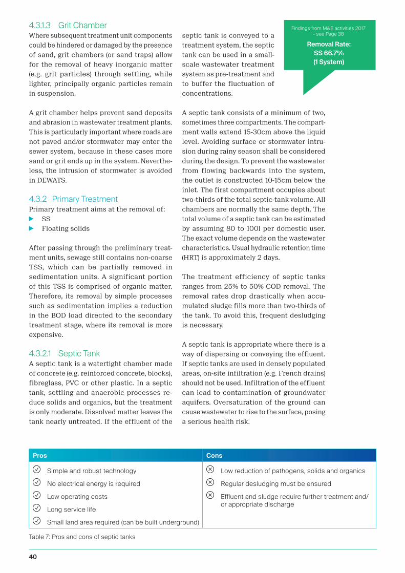
40
4.3.1.3 Grit ChamberWhere subsequent treatment unit components
could be hindered or damaged by the presence
of sand, grit chambers (or sand traps) allow
for the removal of heavy inorganic matter
(e.g. grit particles) through settling, while
lighter, principally organic particles remain
in suspension.
A grit chamber helps prevent sand deposits
and abrasion in wastewater treatment plants.
This is particularly important where roads are
not paved and/or stormwater may enter the
sewer system, because in these cases more
sand or grit ends up in the system. Neverthe-
less, the intrusion of stormwater is avoided
in DEWATS.
4.3.2 Primary TreatmentPrimary treatment aims at the removal of:
i SS
i Floating solids
After passing through the preliminary treat-
ment units, sewage still contains non-coarse
TSS, which can be partially removed in
sedimentation units. A significant portion
of this TSS is comprised of organic matter.
Therefore, its removal by simple processes
such as sedimentation implies a reduction
in the BOD load directed to the secondary
treatment stage, where its removal is more
expensive.
4.3.2.1 Septic TankA septic tank is a watertight chamber made
of concrete (e.g. reinforced concrete, blocks),
fibreglass, PVC or other plastic. In a septic
tank, settling and anaerobic processes re-
duce solids and organics, but the treatment
is only moderate. Dissolved matter leaves the
tank nearly untreated. If the effluent of the
septic tank is conveyed to a
treatment system, the septic
tank can be used in a small-
scale wastewater treatment
system as pre-treatment and
to buffer the fluctuation of
concentrations.
A septic tank consists of a minimum of two,
sometimes three compartments. The compart-
ment walls extend 15-30cm above the liquid
level. Avoiding surface or stormwater intru-
sion during rainy season shall be considered
during the design. To prevent the wastewater
from flowing backwards into the system,
the outlet is constructed 10-15cm below the
inlet. The first compartment occupies about
two-thirds of the total septic-tank volume. All
chambers are normally the same depth. The
total volume of a septic tank can be estimated
by assuming 80 to 100l per domestic user.
The exact volume depends on the wastewater
characteristics. Usual hydraulic retention time
(HRT) is approximately 2 days.
The treatment efficiency of septic tanks
ranges from 25% to 50% COD removal. The
removal rates drop drastically when accu-
mulated sludge fills more than two-thirds of
the tank. To avoid this, frequent desludging
is necessary.
A septic tank is appropriate where there is a
way of dispersing or conveying the effluent.
If septic tanks are used in densely populated
areas, on-site infiltration (e.g. French drains)
should not be used. Infiltration of the effluent
can lead to contamination of groundwater
aquifers. Oversaturation of the ground can
cause wastewater to rise to the surface, posing
a serious health risk.
Removal Rate:SS 66.7%(1 System)
Pros Cons
Simple and robust technology
No electrical energy is required
Low operating costs
Long service life
Small land area required (can be built underground)
Low reduction of pathogens, solids and organics
Regular desludging must be ensured
Effluent and sludge require further treatment and/or appropriate discharge
Table 7: Pros and cons of septic tanks
Findings from M&E activities 2017 - see Page 38

41C O M P O N E N T S O F D E W A T S
4.3.2.2 SettlerA settler is a primary treatment technology
for wastewater; it is designed to remove TSS
by sedimentation. It may also be referred to
as a sedimentation or settling basin/tank, or
clarifier. The low flow velocity in a settler al-
lows settleable particles to sink to the bottom,
while constituents lighter than water float to
the surface. In comparison to septic tanks,
the HRT of a settler is low since anaerobic
digestion is usually not the aim.
The choice of a technology to settle solids is
governed by the size and type of the instal-
lation, the wastewater characteristics, the
management capacities, and the desirability
of an anaerobic process, with or without biogas
production. The installation of a primary sedi-
mentation tank is of particular importance for
technologies that use a filter material. Settlers
can also be installed as stormwater retention
tanks to remove a portion of the organic solids
that otherwise would be directly discharged
into the environment.
sludge
scum
extracted sludge
outletinlet
Figure 12: Section view of a settler (adapted from Tilley, et al., 2014)
Figure 11: Section view of a septic tank (adapted from Tilley, et al., 2014)
Pros Cons
Simple and robust technology
Efficient removal of TSS
Relatively low capital and operating costs
Can be built underground
Low treatment efficiency (only in cases where the settler is not connected to a subsequent treatment)
Table 8: Pros and cons of settlers
access covers vent
sludge
sedimentation zone
scum
inlet-T
outletinlet

42
4.3.2.3 Biogas settlerA DEWATS biogas settler is usually a gas- and
watertight dome-shaped sub-surface struc-
ture. It is typically constructed with bricks or
cement mortar/plaster. The primary function
of the settler is to separate the incoming
wastewater into liquid and solid components,
allowing the digestion of organic solids. The
microbial digestion process occurs under
anaerobic conditions (without oxygen) and
results in the generation of biogas.
The by-products of this treatment process
are (a) a digested slurry (digestate) that is
stabilised and thus can be used as a soil
amendment and (b) biogas that can be used
for energy. Biogas is a mix of methane, carbon
dioxide and other trace gases which can be
converted to heat, electricity or light.
Often, a biogas settler is used as an alter-
native to a septic tank or a settler, since it
offers a similar level of treatment, but with
the added benefit of biogas production. In this
case, the digestate can be further treated (e.g.
in an anaerobic baffled reactor (ABR)). The
accumulated solids must then be desludged
frequently.
This technology can be applied at the house-
hold level, in small neighbourhoods, or for the
stabilisation of sludge at large wastewater
treatment plants. It is best used where regular
feeding is possible. The biogas production is
high for “thick” substrate (low water content).
The water content of wastewater is low enough
to enable operation without stirring.
The reactor volume depends on the HRT. The
longer the HRT, the better the treatment, but
also the larger the reactor. Commonly the HRT
is between 15 and 30 days. The total reactor
volume also depends on the needed storage
volume for the produced gas. This depends on
the gas production and on the pattern of gas
utilisation (e.g. constant usage for a refriger-
ator or variable usage for cooking). External
gas storage (outside of the biogas settler) can
be also implemented. The gas outlet should
be a minimum of 30cm above the substrate
level, to avoid clogging of the outlet by scum.
Figure 13: Section view of a biogas settler(adapted from Tilley, et al., 2014)
Pros Cons
Generation of renewable energy
Small land area required (most of the structure can be built underground)
No electrical energy required
Conservation of nutrients
Long service life
Low operating costs
Low sludge production due to high compression of sludge in the biogas settler
Requires expert design and skilled construction
Requires good O&M capacity
Biogas production using wastewater is low
Biogas emission due to leakage or no usage has a strong negative impact on the climate
Table 9: Pros and cons of biogas settler

43C O M P O N E N T S O F D E W A T S
4.3.3 Secondary TreatmentThe main objective of secondary treatment is
the removal of organic matter. Organic matter
is present in the following forms:
i Dissolved organic matter (soluble or fil-
tered BOD) that is not removed by merely
physical operations, such as the sedimenta-
tion that occurs in primary treatment;
i Organic matter in suspension (suspended
or particulate BOD), which may have been
largely removed in primary treatment, but
whose solids with slower settleability (finer
solids) remain in the liquid mass.
The secondary treatment processes are
conceived in such a way as to accelerate the
decomposition mechanisms that naturally
occur in the receiving waterbodies. Thus,
the decomposition of the degradable organ-
ic pollutants is achieved under controlled
conditions and at smaller time intervals than
in the natural environment.
4.3.3.1 Anaerobic Baffled Reactor (ABR)
An ABR is a modified septic tank with a se-
ries of baffles under which the wastewater
is forced to flow. The increased contact time
with the active biomass (sludge) results in
improved treatment. The up-flow chambers
provide enhanced removal and digestion of
organic matter. BOD can be reduced by 70%
to 90%, which is far superior to its removal in
a conventional septic tank. The main function
of an ABR is the conversion of particulate
matter into soluble BOD, as well as a certain
percentage of soluble BOD into Methane (CH4).
This is achieved by de-coupling HRT from
Solids Retention Time.
This technology is easily adaptable and can
be applied at the household level, in small
neighbourhoods or even in bigger catchment
areas. It is most appropriate where a relatively
constant amount of blackwater and greywater
is generated.
This technology is suitable for areas where
land may be limited, as the tank is most com-
monly installed underground and requires a
small area. However, a vacuum truck should
be able to access the location for desludging
purposes. ABRs are not efficient at removing
nutrients and pathogens. The effluent usually
requires further treatment.
An ABR ideally consists of 3–5 sequential
chambers. The up-flow velocity (max. 1m/h)
limits the height of the reactor. The HRT of
the liquid portion (i.e. above the sludge vol-
ume), which should not be less than 8 hours,
determines the ABR’s volume. This leads to
large but shallow tanks, making the system
uneconomical for large plants. A chamber
should not be longer than 60% of the height.
vent
anaerobic baffled reactor (ABR)
baffle
outlet
access covers
Removal Rate:
SS 83.4 %; COD 43.5 %
TSS 25.0 %; BOD 45.0 %
(8 Systems)
Figure 14: Section view of an ABR(adapted from Tilley, et al., 2014)
Findings from M&E activities 2017 - see Page 38

44
Pros Cons
Simple and durable
Highly resistant to organic and hydraulic shock loads
No electrical energy is required
Low operating and maintenance costs
Low risk of blockage
Long service life
Low sludge production; the sludge is stabilised
Moderate area requirement (can be built underground)
Requires expert design and construction
Low reduction of pathogens and nutrients
Effluent and sludge require further treatment and/or appropriate discharge
Table 10: Pros and cons of an ABR
Figure 15: Section view of an anaerobic filter (AF) (adapted from Tilley, et al., 2014)
4.3.3.2 Anaerobic Filter (AF)An AF is a fixed-bed reactor in an anaerobic
contact process, with one or more filtration
chambers in series. As wastewater flows
through the filter, particles are trapped and
organic matter is degraded by the active bi-
omass that is attached to the surface of the
filter material. Filter material can be gravel,
rocks or specially formed plastic pellets. To
reduce costs, locally available material shall
be used. For example, in Tanzania coconut
husk can be used or in Indonesia volcanic rock
might be a good solution. Good filter material
provides 90m2 to 300m2 surface area per m3.
With this technology, TSS and BOD removal
can be as high as 90%, but typically ranges
between 50% and 80%. Nitrogen removal is
limited and normally does not exceed 15% in
terms of total nitrogen (TN).
This technology is easily adaptable and can
be applied at the household level, in small
neighbourhoods or in bigger catchment areas.
It is most appropriate where a relatively con-
stant amount of blackwater and greywater is
generated. The AF can be used for secondary
treatment, to reduce the organic loading rate
for a subsequent aerobic treatment step, or
for polishing. This technology is suitable for
areas where land may be limited, as the tank
is most commonly installed underground
and requires a small area. Accessibility by
access coversvent
filter
baffle
anaerobic filter units
outlet
Removal Rate:
SS 61.4%; COD 44.0%
TSS 66.7%
(5 Systems)
Findings from M&E activities 2017 - see Page 38

45C O M P O N E N T S O F D E W A T S
vacuum truck is important for desludging. AFs
are not efficient at removing nutrients and
pathogens. Depending on the filter material,
however, complete removal of worm eggs may
be achieved. The effluent usually requires
further treatment. When the bacterial film
on the filter material becomes too thick, it
must be removed. This may be done either by
back-washing or by removing the filter mass
for cleaning outside the reactor.
An important design criterion is the equal dis-
tribution of wastewater across the filter area.
The HRT is about 1.5–2 days. For domestic
wastewater the total volume can be estimated
by assuming 0.5m3/cap - 1m3/cap. A head loss
of 30cm-50cm must be taken into account.
Pros Cons
No electrical energy is required
Low operating costs
Long service life
High reduction of BOD and solids
Low sludge production; the sludge is stabilised
Moderate area requirement (can be built underground)
Requires expert design and construction
Low reduction of pathogens and nutrients
Effluent and sludge require further treatment and/or appropriate discharge
Risk of clogging, depending on pre- and primary treatment
Removing and cleaning the clogged filter media is cumbersome
Filter material can be costly and difficult to obtain locally
Table 11: Pros and cons of anaerobic filters
4.3.3.3 Up-flow Anaerobic Sludge Blanket Reactor (UASB)
The UASB is a single-tank process. Wastewater
enters the reactor from the bottom and flows
upward. A suspended sludge blanket filters
and treats the wastewater as the wastewater
flows through it.
A UASB is not a typical component of a DE-
WATS, mainly because it requires increased
operational skills and capacity. A UASB is not
appropriate for small or rural communities
without a constant water supply or electricity.
The technology is relatively simple to design
and build, but developing the granulated
sludge may take several months. The UASB
has the potential to produce higher quality
effluent than septic tanks and biogas settler
and can do so in a smaller reactor volume.
Although it is a well-established process for
large-scale industrial wastewater treatment
and high organic loading rates up to 10 kg
BOD/m3/d, its application to domestic sewage
is still relatively new.
biogas
outlet
inlet
sludge granule
gas bubbles
Figure 16: Section view of an up-flow anaerobic sludge blanket reactor (UASB) (adapted from Tilley, et al., 2014)

46
UASBs are often used for wastewater from
breweries, distilleries and food processing as
well as pulp and paper waste since the process
typically removes 80 to 90% of COD. General
treatment capacities of 55% to 75% COD re-
duction were observed at average HRTs of 5
to 6 h when treating communal wastewater.
Where the influent is low-strength or where
it contains too many solids, proteins or fats,
the reactor may not work properly.
Pros Cons
High reduction of BOD
Can withstand high organic and hydraulic loading rates
Low sludge production (and thus, infrequent desludging required)
Biogas can be used for energy (but usually first requires scrubbing)
Requires frequent discharge of excess sludge (up to a weekly basis)
Treatment may be unstable with variable hydraulic and organic loads
Requires O&M by skilled personnel; difficult to maintain proper hydraulic conditions (up-flow and settling rates must be balanced)
Long start-up time
A constant source of electricity is required
Not all parts and materials may be locally available
Requires expert design and construction
Effluent and sludge require further treatment and/or appropriate discharge
Table 12: Pros and cons of up-flow anaerobic sludge blanket reactors
4.3.4 Advanced Secondary TreatmentThough primary and secondary treatment
units are capable of removing over 90% of
enteric microbial load, organic matter and
total phosphorus, the effluent from the sec-
ondary treatment units may not meet the
requirements for water reuse or wastewater
discharge in terms of pathogen and nutrient
concentrations. Hence, it is important to
polish the secondary effluent to improve its
hygienic quality and meet the requirements
set for wastewater discharge or reuse (Min-
istry of Urban Development - Government of
India, 2012).
Typically, tertiary treatment units are provided
to polish the secondary effluent and remove
residual contaminants. A tertiary treatment
process can consist of coagulation, solid/
liquid separation and disinfection units for
the removal of residual TSS, colour, organic
matter, offensive odour and microorganisms.
Solid/liquid separation is normally achieved
by filtration, floatation and adsorption.
Disinfection of the pathogenic organisms is
achieved by chlorination or ozonation or UV
disinfection or some combination thereof.
To prevent clogging of the below described
filters with fine soil, stormwater should
neither be mixed with the wastewater be-
fore the treatment step, nor should outside
stormwater be allowed to overflow the filter
bed. Erosion trenches around the filter bed
should always be kept in proper functioning
condition.
Removal Rate:
SS 93.3%; COD 47.0%
TSS 37.9%; BOD 37.3%
(1 System)
Findings from M&E activities 2017 - see Page 38

47C O M P O N E N T S O F D E W A T S
Removal Rate:
SS 75.2%; COD 46.1%
TSS 50.0%; BOD 73.6%
(16 System)
4.3.4.1 Constructed Wetlands (CW)CWs can be distinguished by:
1. The direction of their flow: horizontal
or vertical
2. Their filter material: coarse (e.g. gravel)
or fine (e.g. sand)
3. Their vegetation: planted or unplanted
Horizontal Subsurface Flow Constructed
Wetland or Planted Gravel Filter (PGF)
A horizontal subsurface flow constructed
wetland is a large gravel and sand-filled basin
that is planted with wetland vegetation. As
wastewater flows horizontally through the
basin, the filter material filters out particles
and microorganisms degrade the organics.
The filter media acts simultaneously as a
filter for removing solids, a fixed surface
upon which bacteria can attach, and a base
for the vegetation. Although facultative and
anaerobic bacteria degrade most organics, the
vegetation transfers a small amount of oxygen
to the root zone so that aerobic bacteria can
colonise the area and degrade organics there
as well. The plant roots play an important role
in maintaining the permeability of the filter.
Clogging is a common problem and, there-
fore, the influent should be well settled with
primary and secondary treatment before
flowing into the wetland. This technology
is not appropriate for untreated domestic
wastewater (i.e. blackwater). It is a good
treatment option for communities that have
primary treatment (e.g. septic tanks), but are
looking to achieve a higher quality effluent.
The horizontal subsurface flow constructed
wetland is a good option where land is cheap
and available. Depending on the volume of the
water and the corresponding area require-
ment of the wetland, it can be appropriate
for small sections of urban areas, as well as
for peri-urban and rural communities. It can
also be designed for single households. If the
effluent is to be reused, the losses due to high
evapotranspiration rates could be a drawback
of this technology, depending on the climate.
Pros Cons
High reduction of BOD, TSS and pathogens
Pleasant landscaping possible
Does not have the mosquito problems of the free-water surface constructed wetland
No nuisance from odours
No electrical energy is required
Low operating costs
Requires a large land area
Little nutrient removal
Risk of clogging, depending on pre- and primary treatment
Long start-up time to work at full capacity
Costly if the right quality of gravel is not available
Requires expert design and construction
Table 13: Pros and cons of horizontal subsurface flow constructed wetlands
Figure 17: Section view of a horizontal subsurface flow constructed wetland (adapted from Tilley, et al., 2014)
wetland plants (macrophytes)
slope 1%
liner
small gravel
Findings from M&E activities 2017 - see Page 38

48
Vertical Subsurface Flow Constructed Wetland
A vertical flow constructed wetland is
a planted filter bed that is drained at the
bottom. Wastewater is poured or dosed onto
the surface from above using a mechanical
dosing system. The water flows vertically down
through the filter matrix to the bottom of the
basin where it is collected in a drainage pipe.
The key distinction between a vertical and
horizontal wetland is not simply the direc-
tion of the flow path, but rather the aerobic
conditions.
By intermittently dosing the wetland (4 to 10
times a day), the filter goes through stages
of being saturated and unsaturated, with
the correspondingly different phases of
aerobic and anaerobic conditions. During
a flush phase, the wastewater percolates
down through the unsaturated bed. As the
bed drains, air is drawn into it and the oxygen
has time to diffuse through the porous media.
The filter media acts simultaneously as a
filter for removing solids, a fixed surface upon
which bacteria can attach and a base for the
vegetation. The top layer can be planted. In
this case, the vegetation is allowed to develop
deep, wide roots, which permeate the filter
media. Nutrients and organic material are
absorbed and degraded by the dense micro-
bial populations. By forcing the organisms
into a starvation state between dosing phases,
excessive biomass growth can be decreased
and porosity increased.
The vertical flow constructed wetland is a
good treatment option for communities that
have primary treatment (e.g. septic tanks), but
are looking to achieve a higher quality efflu-
ent. Because of the mechanical dosing system,
this technology is most appropriate where
trained maintenance staff, constant power
supply, and spare parts are available. Since
vertical flow constructed wetlands are able to
nitrify, they can be an appropriate component
of the treatment process for wastewater with
high ammonium concentrations.
Pros Cons
High reduction of BOD, TSS and pathogens
Ability to nitrify due to good oxygen transfer
Does not have the mosquito problems of the free-water surface constructed wetland
Less clogging than in a horizontal subsurface flow constructed wetland
Requires less space than a free-water surface or horizontal flow wetland
Low operating costs
Requires expert design and construction, particularly for the dosing system
Requires more frequent maintenance than a horizontal subsurface flow constructed wetland
A constant source of electrical energy may be required
Long start-up time to work at full capacity
Not all parts and materials may be locally available
Table 14: Pros and cons of vertical subsurface flow constructed wetlands
Figure 18: Section view of a vertical subsurface flow constructed wetland (adapted from Tilley, et al., 2014)
linerslope 1%
air
air pipe
gravel
drainage pipe
80
cm

49C O M P O N E N T S O F D E W A T S
Figure 19: Section view of a vertical sand filter
Vertical Sand Filter
Vertical sand filtration in a DEWATS is com-
parable with the vertical constructed wetland,
only that the filter material is sand. Com-
pared to the horizontal filter, it is the more
efficient and reliable treatment system from
a technical and scientific point of view. One
challenge of vertical sand filtration is the
equal distribution of water on the surface of
the filter, which is realised by feeding in doses.
Doses must be large enough to temporarily
flood the entire filter, but small enough to
allow oxygen to enter before the next flooding.
The sand, therefore, must be fine enough to
allow flooding and porous enough to allow
quick percolation. In addition, resting times
of one to two weeks are needed so that oxy-
gen can enter the filter after wastewater has
percolated.
Vertical sand filters are normally 1- 1.2m deep.
However, if there is enough natural slope and
good ventilation, they can be constructed up
to three meters high. The filters may or may
not be covered by vegetation. In the absence
of vegetation, the surface must be scraped
regularly, in order to allow enough oxygen to
enter. With dense vegetation, the stems of
the plants ensure sufficient open pores in
the filter surface.
The vertical sand filter is not a typical compo-
nent of the DEWATS approach. Dosing of flow
can be challenging, but is typically performed
with self-acting siphons, automated pumps or
tipping buckets. The latter is most suitable
to the DEWATS approach, because its basic
operating principle is easily understood and
the hardware can be manufactured locally.
While vertical filters can bear a hydraulic
load up to 100l/m2xd, it is better to restrict
loading to 50l/m2xd. The organic load may
reach up to 20g BOD/m2xd and in the case
of re-circulation, 40gBOD/m2xd is possible.
Pros Cons
High reduction of contaminants Necessity of permanent operational control
Necessity of a dosing device and a strict adherence to charging intervals
Needs resting periods of one to two weeks
Bad odour might occur during the charging times
Table 14: Pros and cons of vertical subsurface flow constructed wetlands
Removal Rate:
SS 100%; COD 61.2%
TSS 0%; BOD 61.3%
(1 System)
inlet
ventilation
outlet drainage layer
Findings from M&E activities 2017 - see Page 38

50
4.3.4.2 Polishing PondsWastewater treatment ponds are artificial
lakes. They provide wastewater treatment
through natural processes. Different treat-
ment processes can be utilised, depending
on the design of the pond. A series of ponds
can be used to combine different treatment
effects. Ponds may be classified into:
i Sedimentation ponds (pre-treatment with
anaerobic sludge stabilisation)
i Anaerobic ponds (anaerobic stabilisation
ponds)
i Oxidation ponds (aerobic cum facultative
stabilisation ponds)
i Polishing ponds (fully aerobic post-treat-
ment ponds)
In a DEWATS, it is recommended to employ
ponds only as a polishing step, as other uses
of ponds often come into conflict with high
Pros Cons
Can be used for the combined treatment and disposal/reuse of effluent
Has a long lifespan (depending on local conditions)
Low maintenance requirements
Relatively low capital costs; low operating costs
Requires expert design and construction
Requires a large area
Can lead to nuisance like bad odours and mosquito breeding
Primary treatment is required
May negatively affect soil and groundwater properties
Fish may pose a health risk if improperly prepared or cooked
demand for land and produce large amounts
of methane. In addition, ponds are frequently
overloaded or misused as dumpsites. Polish-
ing ponds are shallow and used only for the
final sedimentation of TSS and the reduction
of nutrients. Artificially aerated ponds are
not considered to be part of the DEWATS ap-
proach. DEWATS polishing ponds receive their
oxygen via the water surface and from algae
via photosynthesis. This provides sufficient
oxygen for a loading rate of approximately
4gBOD/m2xd. Polishing ponds can also be used
to grow fish. The fish can feed on algae and
other organisms that grow in the nutrient-rich
water, removing nutrients from the wastewater
until they are eventually harvested for con-
sumption. Simultaneously, the fish assist in
controlling mosquitos.
4.3.5 Treatment of Sludge from DEWATS
After desludging a biogas settler or ABR, the
sludge should be treated in drying beds where
pathogens are killed off through exposure to
oxygen and UV-radiation. In addition, dewater-
ing (or “thickening”) of sludge is an important
treatment objective, as sludge contains a high
proportion of liquid, and the reduction in this
volume will simplify and greatly reduce the
costs of subsequent treatment steps. Environ-
mental and public health treatment objectives
are achieved through pathogen reduction,
stabilisation of organic matter and nutrients,
and the safe end use or disposal of treatment
end-products.
Figure 20: Section view of a polishing/fish pond (adapted from Tilley, et al., 2014)
inlet outlet
sludge liner
Table 15: Pros and cons of polishing/fish ponds

51C O M P O N E N T S O F D E W A T S
4.3.5.1 Unplanted Sludge Drying BedsAn unplanted drying bed is a simple, permea-
ble bed that, when loaded with sludge, collects
percolated leachate and allows the sludge to
dry by evaporation. Approximately 50% to
80% of the sludge volume drains off as liquid
or evaporates. The bottom of the drying bed is
lined with perforated pipes to drain away the
leachate that percolates through the bed. On
top of the pipes are layers of gravel and sand
that support the sludge and allow the liquid
to infiltrate and collect in the pipe. These
layers should not be too thick (maximum 20
cm), or the sludge will not dry effectively. The
final moisture content after 10 to 15 days of
drying should be approximately 60%. When
the sludge is dried, it must be separated from
the sand layer and transported for further
treatment, end-use or final disposal. The lea-
chate that is collected in the drainage pipes
must also be treated properly, depending on
where it is discharged.
Sludge drying is an effective way to decrease
the volume of sludge, which is especially impor-
tant when it has to be transported elsewhere
for further treatment, end-use or disposal.
The technology is not effective at stabilis-
ing the organic component of the sludge or
decreasing the pathogenic content. Further
storage or treatment of the dried sludge might
be required. Unplanted drying beds are best
suited for rural and peri-urban areas where
there is inexpensive, available space situated
far from homes and businesses. If designed
to service urban areas, unplanted drying beds
should be at the edge of the community, but
within economically feasible reach for opera-
tors of motorised emptying services. This is a
low-cost option that can be installed in most
hot and temperate climates. Excessive rain
may prevent the sludge from properly drying.
outlet
drainage water, to treatment
drainage layer
80
cm
Pros Cons
Good dewatering efficiency, especially in dry and hot climates
Can be built and repaired with locally available materials
Relatively low capital costs; low operating costs
Simple operation, only infrequent attention required
No electrical energy is required
Requires a large land area
Odours and flies are normally noticeable
Labour intensive removal
Limited stabilization and pathogen reduction
Requires expert design and construction
Leachate requires further treatment
Table 16: Pros and cons of unplanted sludge drying beds
Figure 21: Section view of an unplanted sludge drying bed (adapted from Tilley, et al., 2014)

52
4.3.5.2 Planted Sludge Drying BedsA planted drying bed is similar to an unplant-
ed drying bed, with the plants bringing the
added benefits of transpiration and enhanced
sludge treatment. The key improvement of the
planted bed over the unplanted bed is that
the filters do not need to be desludged after
each feeding/drying cycle. Fresh sludge can
be directly applied onto the previous layer;
the plants and their root systems maintain
the porosity of the filter. This technology has
the benefit of dewatering and stabilising the
sludge. Also, the roots of the plants create
pathways through the thickening sludge that
allow water to easily escape. The appearance
of the bed is similar to a vertical flow con-
structed wetland. The beds are filled with
sand and gravel to support the vegetation.
Instead of effluent, sludge is applied to the
surface and the filtrate flows down through
the subsurface where it is collected in drains.
This technology is effective at decreasing the
sludge volume (down to 50%) through decom-
position and drying, which is especially impor-
tant when the sludge needs to be transported
elsewhere for end-use or disposal. If designed
to service urban areas, planted drying beds
should be at the edge of the community, but
within economically feasible reach for oper-
ators of motorised emptying services.
Pros Cons
Can handle high loading
Better sludge treatment than in unplanted drying beds
Can be built and repaired with locally available materials
Relatively low capital costs; low operating costs
Fruit or forage growing in the beds can generate income
No electrical energy required
Requires a large land area
Odours and flies may be noticeable
Long storage times
Labour intensive removal
Requires expert design and construction
Leachate requires further treatment
Table 17: Pros and cons of planted sludge drying beds
4.4 Disposal/ReuseDisposal or reuse is the last step in the san-
itation value chain. At this stage the treated
wastewater and sludge have to meet the stip-
ulated treatment requirements. When market
demand can be ensured and the technical
feasibility is proven, reuse is favoured over
Figure 22: Section view of a planted sludge drying bed (adapted from Tilley, et al., 2014)
disposal. Different reuse options and appli-
cations exist for the different by-products,
namely:
i Treated wastewater (effluent)
i Dried and hygienised sludge
i Biogas
screen
grit chamber
sludge
plants
wall
ventilation pipe
mesh gravel/rocks sand
outlet
drainage pipe
drainage layer

53C O M P O N E N T S O F D E W A T S
Requirements and restrictions for reuse are described in the paragraphs below. The World
Health Organisation (WHO) in its “Guidelines for the safe use of wastewater, excreta and
greywater” gives further reliable orientation on the use of wastewater, which can be download-
ed using the following link:
www.who.int/water_sanitation_health/publications/gsuweg4
With the implementation of resource recovery,
it is important to evaluate sludge components
that may impact both humans and the envi-
ronment. These include pathogens and heavy
metals. Social factors such as acceptance of
using products from wastewater treatment
and level of market demand also need to be
taken into account in order to ensure uptake
of the intended end use.
Pathogens
Wastewater contains large amounts of micro-
organisms, mainly originating from the faeces.
The microorganisms can be pathogenic, and
exposure to untreated wastewater constitutes
a significant health risk to humans, either
through direct contact or through indirect ex-
posure. Pathogens are transmitted and spread
through an infection cycle, which includes
different stages and hosts. This cycle can be
interrupted by putting barriers in place to
block transmission paths and prevent cycle
completion.
Wastewater needs to be treated to an ade-
quate hygienic level depending on the end
use or disposal option. The recent 2006 WHO
Guidelines for the Safe Use of Wastewater,
Excreta and Greywater in Agriculture and Aq-
uaculture places less emphasis on treatment
thresholds, but rather highlights a multi-bar-
rier approach where lower levels of treatment
may be acceptable when combined with other
post-treatment barriers along the sanitation
value chain.
The first barrier for beneficial use is provided
by the level of pathogen reduction achieved
through treatment of wastewater. A selection
of further post-treatment barriers may include
a usage restriction on crops that are eaten
raw, withholding periods between application
and harvest to allow pathogen die-off, drip
or subsurface irrigation methods, restricting
worker and public access during applica-
tion, use of personal protective equipment
and safe food preparation methods such as
thorough cooking, washing or peeling. When
considering the risk of infection, all potential
exposure groups should be accounted for.
These can be broadly categorised as workers
and their families, surrounding communities,
and product consumers.
Heavy Metals
Heavy metals are a concern due to their
toxicity and long-term negative effects on
soils. Heavy metals should be evaluated on
a case by case basis, but are only a major
concern if wastewater includes industrial
effluents or stormwater from roads that are
not adequately pre-treated. Heavy metals can
also enter the system at the household level
through the relatively common practice of
improper disposal of wastes containing heavy
metals (e.g. batteries, solvents, paints) into
the system. The total metals concentrations
in the sludge differs from the bioavailable
metals concentrations, as the organic matter
in sludge can bind metals in a form that is not
biologically available.
Social Factors
Different societies and cultures have different
reactions and approaches to the management
of human excreta that have to be taken into
consideration when evaluating the best end
use for wastewater treatment products. Some
cultures reject the use of excreta altogether,
whereas others have a long history of ex-
creta use in agriculture. The use of treated
wastewater is typically perceived differently
from that of excreta, and has a higher ac-
ceptance based on its appearance, smell and
health impacts. This highlights the need for
evaluating the market demand of potential
products prior to deciding on a treatment and
end use scheme.

54
4.4.1 Treated Wastewater
4.4.1.1 Irrigation: distribution systemsTo reduce dependence on freshwater and to
maintain a constant source of water for irriga-
tion throughout the year, wastewater of varying
quality can be used in agriculture. However,
to limit the risk of crop contamination and
health risks to workers, only water that has
had secondary treatment (i.e., physical and bi-
ological treatment) should be used. Examples
of types of irrigation technologies appropriate
for treated wastewater are:
1. Drip irrigation above or below ground,
where the water is slowly dripped on or
near the root area
2. Surface irrigation where water is routed
overland in a series of dug channels or
furrows
3. Sub-surface irrigation where water is
distributed by an underground network
of perforated pipes
To minimise evaporation and contact with
pathogens, spray irrigation should be avoided.
Properly treated wastewater can significantly
reduce dependence on fresh water, and/or
improve crop yields by supplying more water
and nutrients to plants. Raw sewage or un-
treated blackwater should not be used, and
even well-treated water should be used with
caution. Long-term use of poorly or improperly
treated water may cause long-term damage to
the soil structure and its ability to hold water.
Generally, drip irrigation is the most appropri-
ate irrigation method; it is especially good for
arid and drought-prone areas. Surface irriga-
tion is prone to large losses from evaporation
but requires little or no infrastructure and may
be appropriate in some situations. Crops such
as maize, alfalfa (and other feed), fibres (e.g.
cotton), trees, tobacco, fruit trees (e.g. bananas
or mangos) and foods requiring processing
(e.g., sugarcane for sugar production) can be
grown safely with treated effluent. More care
should be taken with fruits and vegetables that
may be eaten raw (e.g. tomatoes, salad or cu-
cumbers), as they could come in contact with
the water. Energy crops like eucalyptus, pop-
lar, willow, or ash trees can be grown in short
rotation and harvested for biofuel production.
Since the trees are not for consumption, this
is a safe, efficient way of using lower-quality
effluent. Soil quality can degrade over time
(e.g. due to the accumulation of salts) if poorly
treated wastewater is applied.
Figure 23: Sketch of a drip irrigation system with treated wastewater
Pros Cons
Reduces depletion of groundwater and improves the availability of drinking water
Reduces the need for fertiliser
Potential for local job creation and income generation
Low risk of pathogen transmission if water is properly treated
Low capital and operating costs depending on the design
May require expert design and installation
Not all parts and materials may be locally available
Drip irrigation is very sensitive to clogging, i.e., the water must be free from TSS
Risk of soil salinisation if the soil is prone to the accumulation of salts
Social acceptance may be low in some areas
Table 18: Pros and cons of irrigation with treated wastewater
treated effluent

55C O M P O N E N T S O F D E W A T S
4.4.1.2 Discharge to the ground: Leach fields using French Drains
Water can be discharged into the ground.
Groundwater recharge is increasing in popu-
larity as groundwater resources deplete and as
saltwater intrusion becomes a greater threat to
coastal communities. Although the soil is known
to act as a filter for a variety of contaminants,
groundwater recharge should not be viewed as
a treatment method. Once an aquifer is con-
taminated, it is next to impossible to reclaim
it. Groundwater recharge is most appropriate
for areas that are at risk of saltwater intrusion
or aquifers that have a long retention time.
A leach field, or drainage field, is a network of
perforated pipes (French Drains) that are laid in
underground gravel-filled trenches to dissipate
the effluent from a water-based small-scale
wastewater treatment system used to infiltrate
water. Each trench is 0.3 to 1.5m deep and 0.3
to 1m wide. The bottom of each trench is filled
with about 15cm of clean rock and a perforated
distribution pipe is laid on top. More rock is
placed to cover the pipe. A layer of geotextile
fabric is placed on the rock layer to prevent
small particles from plugging the pipe. A final
layer of sand and/or topsoil covers the fabric
Table 19: Pros and cons of discharging treated wastewater using French Drains
and fills the trench to the ground level. The pipe
should be placed at least 15cm beneath the
surface to prevent effluent from surfacing. The
trenches should be dug no longer than 20m in
length and at least 1 to 2m apart. A leach field
should be laid out such that it will not lead to
contamination of freshwater sources and not
interfere with a future sewer connection.
Leach fields require a large area and unsatu-
rated soil with good absorptive capacity to
effectively dissipate the effluent. Due to po-
tential oversaturation of the soil, leach fields
are not appropriate for dense urban areas.
Trees and deep-rooted plants should be kept
away from the leach field as their roots can
crack and disturb the tile bed. Nevertheless,
if well designed a French Drain can also be
applied as a distribution system for irrigation
(see Chapter 4.4.1.1).
Since the technology is underground and re-
quires little attention, users will rarely come
in contact with the effluent and, therefore, it
has no health risk. The leach field must be kept
as far away as possible (at least 30 m) from
any potential potable water source to avoid
contamination.
Pros Cons
Can be used for the combined treatment and disposal/reuse of effluent
Has a long lifespan (depending on local conditions)
Low maintenance requirements
Relatively low capital costs; low operating costs
Requires expert design and construction
Requires a large area
Primary treatment is required to prevent clogging
May negatively affect soil and groundwater properties
septic tank
settled effluentFigure 24: Sketch of a leach field (adapted from Tilley, et al., 2014)

56
inlet
4.4.1.3 Discharge to the ground: Soak Pits
A soak pit, also known as a soak-away or a leach
pit, is a covered, porous-walled chamber that
allows water to slowly soak into the ground. Ef-
fluent from a collection and storage/treatment
or (semi-) centralised treatment technology
is discharged to the underground chamber
from which it infiltrates into the surrounding
soil. As wastewater (greywater or blackwater
after primary treatment) percolates through
the soil from the soak pit, small particles are
filtered out by the soil matrix and organics are
digested by microorganisms. Thus, soak pits
Figure 25: Section view of a soak pit ( Tilley, et al., 2014)
Table 20: Pros and cons of soak pits
are best suited for soil with good absorptive
properties; clay, hard-packed or rocky soil is
not appropriate.
A soak pit does not provide adequate treat-
ment for raw wastewater, and the pit will quick-
ly clog. It should only be used for discharging
blackwater or greywater that has been through
at least primary treatment. Soak pits are
appropriate for rural and peri-urban settle-
ments. They depend on soil with a sufficient
absorptive capacity. They are not appropriate
for areas prone to flooding or that have high
groundwater tables.
Pros Cons
Can be built and repaired with locally available materials
Technique is simple to apply for all users
Small land area required
Low capital and operating costs
Primary treatment is required to prevent clogging
May negatively affect soil and groundwater properties
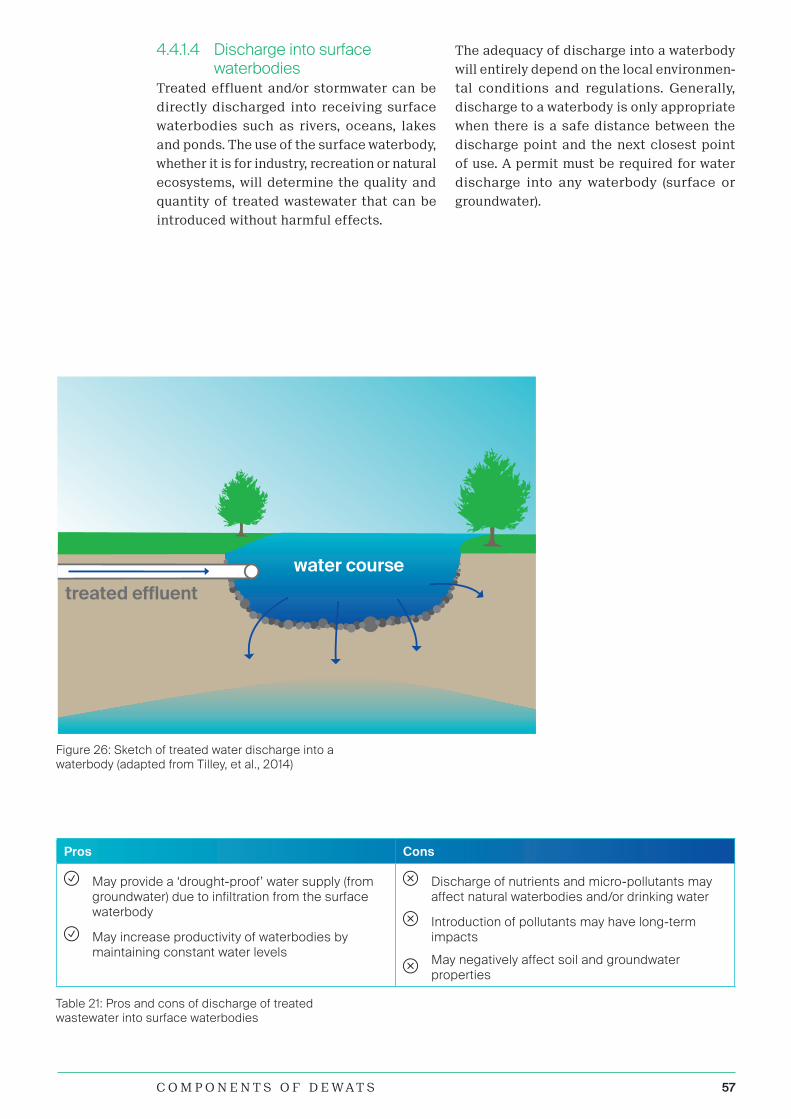
57C O M P O N E N T S O F D E W A T S
water course
treated effluent
Figure 26: Sketch of treated water discharge into a waterbody (adapted from Tilley, et al., 2014)
4.4.1.4 Discharge into surface waterbodies
Treated effluent and/or stormwater can be
directly discharged into receiving surface
waterbodies such as rivers, oceans, lakes
and ponds. The use of the surface waterbody,
whether it is for industry, recreation or natural
ecosystems, will determine the quality and
quantity of treated wastewater that can be
introduced without harmful effects.
Pros Cons
May provide a ‘drought-proof’ water supply (from groundwater) due to infiltration from the surface waterbody
May increase productivity of waterbodies by maintaining constant water levels
Discharge of nutrients and micro-pollutants may affect natural waterbodies and/or drinking water
Introduction of pollutants may have long-term impacts
May negatively affect soil and groundwater properties
Table 21: Pros and cons of discharge of treated wastewater into surface waterbodies
The adequacy of discharge into a waterbody
will entirely depend on the local environmen-
tal conditions and regulations. Generally,
discharge to a waterbody is only appropriate
when there is a safe distance between the
discharge point and the next closest point
of use. A permit must be required for water
discharge into any waterbody (surface or
groundwater).

58
4.4.2 Treated SludgeDepending on the treatment type and quality,
digested or stabilised sludge can be applied to
public or private lands for landscaping or ag-
riculture. Sludge that has been treated can be
used in agriculture, home gardening, forestry,
sod and turf growing, landscaping, parks, golf
courses, mine reclamation, as a dump cover,
or for erosion control. Although sludge has
lower nitrogen, phosphorus and potassium
levels than commercial fertilisers, it can be an
effective substitute for a significant portion
of chemical fertiliser. Additionally, treated
sludge has been found to have properties su-
perior to those of commercial fertilisers, such
as bulking and water retention properties, and
the slow, steady release of nutrients.
Although sludge is sometimes criticised for
containing potentially high levels of metals
or contaminants, commercial fertilisers
are also contaminated to varying degrees,
most likely with cadmium or other heavy
metals. Sludge that originates at large-scale
wastewater treatment plants is more likely to
be contaminated since it receives industrial
and domestic chemicals as well as surface
water run-off which may contain hydrocarbons
and metals. Application of sludge on land may
be less expensive than disposal. Depending on
the source of the sludge and on the treatment
method, sludge can be treated to a level where
it is generally safe and no longer generates
significant odour or vector problems.
Pros Cons
Can reduce the use of chemical fertilisers and improve the water-holding capacity of soil
Can accelerate reforestation
Can reduce erosion
Low costs
Odours may be noticeable, depending on prior treatment
May require special spreading equipment
May pose public health risks, depending on its quality and application
Micro-pollutants may accumulate in the soil and contaminate groundwater
Social acceptance may be low in some areas
Table 22: Pros and cons of the application of treated sludge in agriculture
Figure 27: Application of treated sludge in agriculture (adapted from Tilley, et al., 2014)
sludge
sludge

59C O M P O N E N T S O F D E W A T S
Pros Cons
Free, renewable and off-grid source of energy
Reduction of indoor air pollution and deforestation (if firewood or coal was previously used)
May not fulfil total energy requirements
Cannot replace all types of energy
Cannot be easily stored (low energy density per volume) and thus needs to be continuously used
M&E results show that a significant percentage of systems is not operational, or the produced biogas is not utilised
The emission of unburned biogas has a negative impact on the climate
Table 23: Pros and cons of biogas combustion
Figure 28: Examples of biogas appliances (adapted from Tilley, et al., 2014)
4.4.3 Biogas In principal, biogas can be used like other
fuel gas. When produced in household-level
biogas settler, it is most suitable for cook-
ing. Additionally, electricity generation is a
valuable option, but only when the biogas is
produced in large anaerobic settlers.
The biogas is trapped, pressurised and dis-
tributed to the consumer. Household energy
demand varies greatly and is influenced by
cooking and eating habits (i.e. hard grains
and maize may require substantial cooking
times and therefore more energy compared
to cooking fresh vegetables and meat). Biogas
has an average methane content of 55-75%.
As a rule of thumb, 1m³ biogas is equivalent
to approximately 6kWh of electric energy and
can substitute about 5kg of firewood or 0.6l
of diesel fuel.
Only 2 of 7 systems with a biogas settler had func-
tioning appliances. None burned off unused biogas.
The calorific efficiency of using biogas is 55%
in stoves, 24% in engines, but only 3% in lamps.
Thus, the best use of biogas is heat production:
for cooking in homes and canteens or for dry-
ing and heating as part of industrial processes.
Biogas burners can be made from converted
LPG burners. The minimum amount of biogas
required for a household kitchen (~5-8 people)
is approximately 1m³/d. Producing this amount
of biogas requires domestic wastewater from
about 8-10 households or 15kg of organic waste
or the manure from 5 pigs or 1-2 cows. These
numbers give only a rough approximation of
what is needed to provide a household with
cooking energy and can widely differ depend-
ing on many parameters.
Findings from M&E activities 2017 - see Page 38

60
4.5 DEWATS Module CombinationsThis chapter aims to provide examples of
possible combinations and configurations of
DEWATS modules, including their treatment
performance and basic requirements (e.g.
land area, capital costs and operation costs).
Globally, 70% of DEWATS include a settler,
38% a biogas settler, 38% an ABR, 25% an AF
and 18% a PGF. The most popular combination
of modules includes a settler and an ABR, in
some cases also followed by an AF. All of the
treatment performances and requirements
mentioned below are approximations, depend-
ent on the context. Therefore, any information
provided below shall not be used for detailed
project planning.
Average treatment performance of a modular combination of ABR, AF and CW:
Inlet Outlet
SS [mg/l] 3.6 0.1
COD [mg/l] 382.8 87.5
BOD [mg/l] 160 75.5
TSS [mg/l] 35 20
(6 Systems)
Biogas settler and ABR Inlet Outlet Requirement
TSS [mg/l] 350 250 Area: 0.1m2/cap
CAPEX: 20USD/cap.
OPEX: 5USD/cap*a
COD [mg/l] 1,400 350
PO4-P [mg/l] 15 15
NH4-N [mg/l] 20 85
FC [No/100ml] 1012 107
Biogas settler, ABR, AF and PGF Inlet Outlet Requirement
TSS [mg/l] 350 30 Area: 0.25-0.6m2/cap.
CAPEX: 80-120USD/cap.
OPEX: 5-10USD/cap*a
COD [mg/l] 1,400 100
PO4-P [mg/l] 15 10
NH4-N [mg/l] 20 70
FC [No/100ml] 1012 105
Septic tank, ABR, AF, Vertical Sand Filter and UV Inlet Outlet Requirement
TSS [mg/l] 350 25 Area: 1.0m2/cap.
CAPEX: 150-200USD/cap.
OPEX: 8-15USD/cap*a
COD [mg/l] 1,400 60
PO4-P [mg/l] 15 6
NH4-N [mg/l] 20 10
FC [No/100ml] 1012 103
baffle
sludge
sedimentation zone
Findings from M&E activities 2017 - see Page 38

61C O M P O N E N T S O F D E W A T S
BORDA Tanzania Office DEWATS, Mikocheni, Dar es Salaam.On-site wastewater management system (designed by BORDA Tanzania) with biogas settler, ABR, PGF, polishing pond, and french-drain. The system produces biogas for cooking purposes, and treated wastewater is used to irrigate the office compound.

5 Phases of a DEWATS Project

63P H A S E S O F A D E W A T S P R O J E C T
The activities conducted in the process of
implementing and operating a DEWATS are
laid out in the QMS. The QMS include Stand-
ard Operating Procedures (SOPs). A general
overview of the DEWATS implementation and
operation process is presented in the flow-
chart below (Figure 28). The SOPs distinguish
between projects for single household con-
nections, institutional systems, and cluster
or community systems.
Process ignition if Cluster System
Launching of the planning process
Prioritization of the community problems
Detailed assessment of the current situation if Cluster System
Determine final system options
Development of an action plan
Implementation and capacity building
O&M, M&E and training as required Figure 29: General overview of the DEWATS implementation and operation process

64
5.1 Planning and Design
For detailed information on the planning and implementation procedures of DEWATS
– in addition to the abstracts mentioned below – the following documents should be
consulted (see Chapter 4 for references on DEWATS design, which are not repeated
here):
1. Parkinson, J., Lüthi, C., & Walther, D. (2014). Sanitation 21: A Planning Framework
for Improving City-Wide Sanitation Services. IWA; Eawag-Sandec; GIZ.
2. Lüthi, C., Morel, A., Tilley, E., & Ulrich, L. (2011). Community-Led Urban Environ-
mental Sanitation Planning (CLUES). Eawag-Sandec, WSSCC, UN-HABITAT.
3. Strande, L., Ronteltap, M., & Brdjanovic, D. (Eds.) (2014). Faecal sludge man-
agement: Systems approach for implementation and operation, Faecal Sludge
Management: Systems Approach for Implementation and Operation. IWA.
4. ESCAP; UN-Habitat; AIT. (2015). Policy Guidance Manual On Wastewater Man-
agement: With A Special Emphasis On Decentralized Wastewater Treatment
Systems .
5. Policy Guidance Manual On Wastewater Management: With A Special Emphasis
On Decentralized Wastewater Treatment Systems; ESCAP, UN-Habitat & AIT;
2015
6. McConville, J. (2010). Unpacking Sanitation Planning - Comparing Theory and
Practice. Chalmers University of Technology.
Sanitation planning requires understanding
and matching stakeholders’ interests, needs
and constraints in an enabling environment.
Common reasons for failure of sanitation
projects are the implementation of infrastruc-
ture without:
i Consulting the main stakeholders
i Planning adequate O&M and financial
schemes
i The availability of adequate skills
i Sufficient organisational capacity
Demand for sanitation is often minimal,
particularly in low- and middle-income coun-
tries, so fostering a demand for wastewater
treatment can be seen as the first step in the
chain of implementing sanitation services.
Interventions to increase household and
community demand for sanitation typically
include:
i Promotion of the benefits of sanitation
i Marketing of specific sanitation products
i Hygiene promotion
i Social development
i Mobilisation (often linked to the forma-
tion of community groups in urban areas)
i Community triggering
Several approaches have been developed to
help planners in defining appropriate man-
agement strategies, which differ according to
the scale and location of implementation (e.g.
households with single connections, institu-
tions, communities with ‘cluster’ systems or
whole cities), the planning perspective (bot-
tom-up vs. top-down) and the funding source
(development partner or national resources).
The planning model needs to encompass the
entire system and all project phases, includ-
ing participatory planning stages. Integrated
planning needs to link different levels, as
the management needs to be organised city-
wide – by the Local Government Authority
(LGA) in a close relationship with the users
and operators.
The City Sanitation Planning (CSP) approach for Dar es Salaam was created in
response to the need for a simple, fast and flexible tool for determining “which
sanitation solutions go where”. All information related to this can be found here:
www.citysanitationplanning.org

65P H A S E S O F A D E W A T S P R O J E C T
5.1.1 Launching of the planning process
Groundwork should start with the identifica-
tion and preliminary characterisation of the
stakeholders and the relationships between
them. To initiate the planning process, it is
recommended that key stakeholders are invit-
ed to a launching workshop, where all partici-
pants can develop a common understanding of
the situation in the intervention area, as well
as agree on the process of how to solve the
problems. This common understanding, which
encompasses particular group dynamics and
stakeholders’ interests, is very important and
can never be assumed. Experience shows that
many stakeholders, especially local authori-
ties, are usually not aware of the situation on
the ground. For this reason, it is recommended
that a field visit for all stakeholders is includ-
ed as part of the launching workshop in order
to raise awareness.
Government and utility representatives should
be involved in the launching workshop, in
order to avoid potential conflicts with existing
policies, regulations and municipal by-laws.
Their participation will also help clarify the
available support and skills at municipal or
district levels. This workshop should also aim
at:
i Creating awareness amongst deci-
sion-makers of legal requirements, re-
quired resources and institutional backing
i Developing an enabling environment,
and getting different stakeholders and
authorities to offer their competencies
i Launching a process for the provision of
financial and human resources at differ-
ent government levels
Once all stakeholders are sensitised to the
sanitation reality and aware of the project
objectives, it will be much easier to collect
information for the feasibility studies. It is
often not easy to access data, especially where
‘information is power’, and it is important to
make key contacts and build trust through
transparency. At the end of this phase, the
process leaders should have a clear idea of
feasible options and key stakeholders.
The detailed assessment of the local context
and the current situation shall include the
following:
i Detailed stakeholder map
i Status of the enabling environment (in-
stitutional setup, government support,
financial arrangements, socio-cultural
acceptance, legal framework, skills and
capacities)
i Sanitation practices, needs and reuse
interests
i Identification of potential sites
i SWOT analysis of the project
The launching activities are especially rele-
vant for the implementation of community
wastewater treatment solutions as clusters
systems.
5.1.2 Feasibility StudyThe main result of the feasibility study is the
identification of viable system options. This
phase starts with an in-depth analysis of the
current situation, such as the quantification
and characterisation of wastewater flows, as
a prerequisite for the selection and design
of technical options. A characterisation and
selection of sites should also be made as
this may influence the viability of different
technical options. The concept development
and detailed analysis conducted during the
feasibility study includes:
i Characterisation and quantification of
wastewater
i Site selection
i Technology selection
i Institutional setups and financial flow
models
i Cost-recovery mechanisms and cost-ben-
efit analysis for the system’s lifecycle
i Several system scenarios
i Iterative optimisation loops of scenarios
with stakeholders
Based on this and the information collected
during the launching of the planning process,
technical, organisational and financial op-
tions can be preselected, studied in depth,
and discussed in a participatory manner. It is
crucial to recognise that sanitation planning
is not about single ‘stand-alone’ technologies.
Rather, it is about the combination of services
and how different factors correlate. Each sce-
nario should be evaluated in detail as follows:
i Requirements for technology combina-
tions, and their pros and cons (e.g. O&M
requirements)

66
i Management and institutional setups,
roles and responsibilities, and contractual
arrangements
i Capital and operation costs, financial
mechanisms and estimated budget
i Capacity building and training needs
i Environmental impact
Each scenario should be examined in conjunc-
tion with the requirements for an enabling
environment. If an aspect of the scenario
does not meet the requirements, it should
be either adapted or activities should be
carried out to create the missing conditions.
The strengths, limitations and implications of
the preselected systems should be assessed.
It is important to involve the key stakeholders
in the evaluation, as they will have to take over
the roles and responsibilities of the system.
It is also important that stakeholders are
properly informed.
At the end of the phase, it is recommended
to organise a validation workshop with all
the key stakeholders, in order to publicly and
officially present and validate the decisions
taken. Any disagreement from important and/
or influential stakeholders should be cleared
before the public workshop. The feasibility
study report should state clearly who the main
stakeholders for the next phase will be. For
this reason, it is recommended at this point
to reassess the interest and influence of the
key stakeholders according to the validated
options.
5.1.3 Site and Technology SelectionThe first step in the technical planning of
small-scale DEWATS is the site selection.
The wrong site location is likely to impact
adversely on the long-term sustainability of
the service. Politicians, landowners, town
planners, residents, operators and users
are all likely to have differing priorities and
requirements as to where the infrastructure
should be located. Decisions may be heavily
biased. Political pressure for available space
may override what is considered appropriate
for the users and host community. Potential
and existing sites need to be identified
through discussions and site visits with key
stakeholders.
As such, the most appropriate technology
is the technology that is economically af-
fordable, environmentally sustainable and so-
cially acceptable. The decision regarding the
wastewater treatment process to be adopted
should be derived from a balance of:
i Technical feasibility (adequate to
treatment objective)
i Economic viability/affordability for
communities
i Social and cultural acceptance
i Legal aspects
i Environmental sustainability
There are no generalised formulas for the opti-
mal solution to site and technology selection.
To structure the decision-making process,
criteria and weightings can be attributed to
the various factors and analysed in a Multiple
Criteria Decision Analysis (MCDA), so that the
selection really leads to the most appropriate
alternatives. Experience and common sense
when attributing the relative importance of
each technical aspect are essential. While
the economic side is fundamental, it needs
to be remembered that the best option is not
always the one that simply presents the lowest
cost in economic–financial studies. Table 22
lists the main factors that influence the site
and technology selection.
5.1.4 Flood ProtectionThe planning and design (including the site
and technology selection) of DEWATS should
take into account protection against flooding.
Every treatment plant must be positioned so
that it is not subject to flooding or is otherwise
protected from flooding, and has all-weather
road access. The treatment process units
should be located at an elevation higher
than the 100-year flood level or otherwise be
adequately protected against 100-year flood
damage. Newly constructed plants should
remain fully operational during a 100-year
flood event.

67P H A S E S O F A D E W A T S P R O J E C T
Influencing Factor S T Influencing Factor S T
Land Social / Cultural
Availability of space / landUser preferences / social and cultural acceptance
Soil and groundwater characteristicsCommunity’s willingness and ability to pay and connect to wastewater treatment system
Distance between place of wastewater generation and treatment plant
Skills and capacity for implementation and operation
Topography Nuisance control
Flooding risk Process Related
Technology / Material / Infrastructure Available
Desired output products
Availability and condition of existing sani-tation technology: sewer connections and current wastewater management systems
Management considerations
Local availability and cost of materials Environment and public health impact
Robustness of technology that is needed and available
Sludge generation and quality
Construction requirements O&M requirements
Road access Health and safety
Availability of electricity Government / NGO support
FinanceProgrammes or strategies related to sanitation
Financial resources Acts, regulations and standards
O&M costs Availability of Data
Capital costs Maps, statistics, surveys, etc.
Expenses for wastewater (tariffs) Water and Wastewater
PopulationWastewater characteristics: Volume and quality
Population and households in coverage area
Water availability, reliability of supply and usage patterns
Number of enterprises and institutions in coverage area
Effluent standards for discharge and reuse
Table 24: Factors influencing the selection of the site (S) and the technologies (T)

68
5.1.5 Detailed Project Development – Action Planning
Based on the options validated in the previous
phases, an action plan can be developed. This
action plan should include the following items:
i Detailed design and drawings of the treat-
ment system
i Bills of quantities (BOQs) and procurement
plans
i Detailed definition of roles and respon-
sibilities in the new system and terms of
references
i O&M management plan with a clear
allocation of costs, responsibilities and
training needs
i Written agreement between stakehold-
ers, securing financial and institutional
mechanisms
i Strategy for control (M&E) and enforce-
ment, including the frequency of control,
the means needed and sanctions
i Planning of capacity building and iden-
tification of human resource needs and
options for job creation
i Definition of contracts and bidding
processes
i M&E strategy for the implementation
phase
i Timeline for implementation with distinct
phases, milestones and an itemised im-
plementation budget
Unsatisfactory O&M is often a cause of failure
in wastewater treatment projects and thus
the O&M management plan is particularly
important. The whole action plan should
be presented, discussed and validated in a
workshop with all the key stakeholders. Key
stakeholders should be reassessed according
to the definition of roles and responsibilities.
Several workshops may be needed until a
consensus is reached.
During this project phase all legally required
permits need to be obtained. In addition, an
environmental impact assessment should be
conducted at this stage, if required.
5.2 ImplementationThis phase is mainly about translating the
action plan into work packages that will ulti-
mately become contracts for implementing
the DEWATS. Several arrangements are appli-
cable for the implementation of the plans, the
most common being through private sector
contractors based on competitive tendering
and bidding procedures.
In parallel to this process, stakeholders should
be organised according to the action plan.
If needed, the legal and regulatory frame-
work should be adapted or appended with
by-laws. According to the identified needs,
capacity building should be provided for a
smooth transfer of roles and responsibilities.
The public should also be properly informed
about or even involved in the intervention and
the improvements being carried out in their
municipality. This will increase awareness and
a sense of ownership shared by the public and
the authorities. Before the inauguration of the
treatment plant, the strengths, weaknesses
and training needs of key stakeholders should
be reassessed. At this point there is still time
to organise further training and adapt the
capacity-building strategy.
5.3 Handover and start-upAfter finalising the construction work and
ensuring all modules are watertight, the whole
system–including infrastructure and stakehold-
ers–requires a start-up phase for acclimatisa-
tion. During this phase, all responsibilities are
handed over from the contractors and planners
to the owner of the system. The management
and the operator take over all tasks and start
the operation. The stakeholders will need
some time to get used to their new roles and
responsibilities, and some adjustments will
certainly be needed over the first few months
of operations. Support from the project team
is of particular importance during this phase.
During this period all relevant documents are
handed over to the owner of the plant. Although
the system is operational, the consultant is
still present to assist in the start-up processes
and to respond to challenges. Within the first
6 months of operation, the contractors are gen-
erally responsible for damages (defect liability
period). Finally, an inauguration ceremony can
be organised. Such an event can generate pub-
lic interest and increase awareness, and can
also have a positive influence on institutional
decision makers.
Effluent concentrations will be high during
the start-up phase of the reactors. The av-
erage start-up period (defined as the period
before stable effluent concentrations can be

69P H A S E S O F A D E W A T S P R O J E C T
expected) of DEWATS reactors is estimated
at three to six months. The treatment perfor-
mance depends on the availability of active
bacterial mass in the reactors. Inoculation of
the biogas settler, the ABR and the AF with
old sludge (e.g. from septic tanks) shortens the
start-up period. In principle, it is advantageous
to start with only a quarter of the daily flow
and with slightly stronger wastewater. The
loading rate should increase slowly over three
months. This provides bacteria with enough
time to multiply before solids are washed out.
Starting with the full hydraulic load from the
beginning will severely delay maturation.
In CWs and PGFs, young plant seedlings
may not grow on wastewater. Therefore, it
is advisable to start feeding the system with
plenty of fresh water and to let the pollution
load increase parallel to plant growth. When
plants are under full load, the outlet level is
adjusted according to flow. Water should not
stand on the surface of the PGF near the inlet.
If this happens, the swivel arm at the outlet
should be lowered.
5.4 Operation and Maintenance (O&M)
Challenges in O&M are one of the main rea-
sons for the failure of DEWATS. The feasibility
of an adequate O&M is an effect of the qual-
ity of planning, design and implementation.
“Operation” refers to all the activities that
are required to ensure that a DEWATS de-
livers treatment services as designed and
“maintenance” refers to all the activities that
ensure long-term operation of equipment and
infrastructure. Having skilled workers per-
form these tasks in a timely manner and in
accordance with best practices will maximise
the efficiency of the DEWATS and ensure its
long-term performance.
Financial, technical and managerial inputs
are needed to ensure the continuous oper-
ation of even the simplest of DEWATS. The
procedures that establish how the treatment
facility and equipment should be utilised are
documented in several O&M plans, monitoring
programmes, reports, log books, and health
and safety plans, which outline the step-by-
step tasks that employees are required to
carry out in order to ensure the long-term
functioning of the DEWATS. The O&M man-
agement plan that is developed during the
detailed project planning phase—and that
must be carefully followed—should include:
i O&M tasks encompassing routine opera-
tions, preventive maintenance (inspection
and periodic maintenance) and reactive
maintenance (repairs)
i Tools and equipment lists, with
descriptions
i Safety procedures, rules and equipment
i O&M costs
i Administrative tasks including bookkeep-
ing, collecting fees, annual budgeting,
paying employees and dealing with
complaints
i Monitoring and sampling procedures
i Reporting procedures
i Responsibilities of all parties concerned
i Training activities for responsible persons
During M&E activities, it was observed that only 8 of 21 operators had received adequate training, and
in most cases there were insufficient tools for O&M. Due to these findings, the following is suggested:
• Improved and more frequent training should be provided for operators
• O&M tools must be provided on-site and activities like removing blockages and repairing broken toilets must be carried out regularly to ensure an adequate service for the users

70
5.4.1 OperationDEWATS require clear operational procedures.
The operational procedures should take all
context-dependent variables (e.g. wastewater
characteristics, local legislation, climate)
into account. The customised O&M manual
and O&M plane should include the following
information:
i The engineering drawings and DEWATS
specifications
i The responsible person for each task
i The frequency of each activity
i The operational procedures and tools
required to perform each task
i The chemicals and other consumables re-
quired, along with their suppliers, storage
and application
i The safety measures required
This chapter is based on content extracted from the publications listed below. For further
detailed information on the O&M of DEWATS, these documents should be consulted:
1. Simwambi, A., Tembo, M., & Wolter, D. (2016). DEWATS Engineers Operations, Mainte-
nance & Management Manual. WAZASA; BORDA.
2. BORDA. (2008). Operational Tasks for the Upkeep of Decentralised Wastewater Treat-
ment System (DEWATS). Bangalore, India: CDD Society.
3. Leitao, R., van Haandel, A., Zeeman, G., & Lettinga, G. (2006). 3. The effects of oper-
ational and environmental variations on anaerobic wastewater treatment systems: A
review. Bioresource Technology, 1105 – 1118.
i The organisational structure, distribu-
tion and management of administrative
responsibilities
i The information that is to be monitored
and recorded
i Emergency and non-routine operational
requirements
All procedures provided in the operation
manual must be adapted in order to ensure
conformance with local laws and standards.
The performance and service lifespan of the
DEWATS also largely relies on basic opera-
tional tasks done at household facilities such
as toilets, sewer lines, manholes and biogas
stoves. Operation of the DEWATS also includes
tasks such as proper toilet and biogas use. A
summary of the operational tasks and their
frequencies is presented in Table 23.

71P H A S E S O F A D E W A T S P R O J E C T
Table 25: Operational tasksOperational tasks
Facility Task Frequency
Multiple Modules Removal of solid waste from all manholes, reactors, inlets, outlets and sewers
Monthly, and more frequently when large quantities are observed
Removal of scum and grease from all manholes, reactors, grease traps, inlets and outlets
Monthly, and when large quantities are observed, depending on wastewater characteristics
Further treatment and disposal of solid wastes
Whenever removed from the treatment units
Oiling of movable parts such as locks, doors and handles of manhole covers
Monthly
Cleaning and care of the site (e.g. management of vegetation)
Weekly
Extraction and further treatment and/or disposal/reuse of end products
Depends on reuse/disposal
Management and documentation of material stock
Weekly
Washing particle filter Once in 6 months, depending on wastewater characteristics
Screens, Grit Chamber and Grease Trap
Cleaning of solid waste screens Daily
Removal of grit Daily
Removal of oil, grease and other floatables Daily
Treatment and/or disposal of screening material and other removed material
With removal (daily)
Biogas settler and Applications
Poking and stirring the floating organic material into the water
Weekly, and depending on feeding material
In case of feeding with organic solid waste, poke and stir
Each feeding time
Releasing water from water trap(s) Weekly
Cleaning of biogas burners Monthly
Gas utilisation or disposal (combustion) Continuously (daily)
CW / PGF Management of vegetation Monthly
Removing leaves, soil and solid waste accumulated at the surface of the filter
Monthly
Vertical Sand Filter Removing leaves, soil and solid waste accumulated at the surface of the filter
Monthly
Pond System Weeding, removal of leaves and other litter Monthly
Effluent distribution system
Control of water flow through control chambers
Monthly
Sludge Drying Bed Preparation of drying beds and channels With desludging
Management of vegetation Monthly
Filling the bed(s) with sludge As desludging
Control sludge flow to and the distribution of sludge in the drying bed
As desludging
Cleaning of sludge flow channels As desludging
Monitoring of drying process Weekly
Packaging the dried soil conditioner, transportation and storage
On demand
Direct utilisation of soil conditioner, organisation of transport to municipal landfill site or sale to private company for reuse
On demand

72
5.4.2 MaintenanceThere are two main types of maintenance
activities: preventative maintenance and
reactive maintenance. Preventive mainte-
nance includes all routine or scheduled work
activities required to keep the installations
in conditions so that the operations can be
done successfully. Reactive maintenance
includes all work activities aimed to restore
the installations or equipment to its normal
operating conditions after occurred failures
or breakdowns. Maintenance tasks can be
performed by operators or specialised per-
sonnel, depending on the capacities of the
operator and the O&M strategy. It is important
that the tasks and the people in charge are
clearly defined and documented for each
wastewater treatment system. Well-planned
preventative maintenance programmes can
often minimise reactive interventions to
emergency situations, which are frequent-
ly costlier and more complex. Component
breakdowns at DEWATS can result in wider
system failure. Therefore, each component
at the DEWATS has specific preventative
maintenance requirements that need to be
described in detail in a maintenance plan
including the tasks, frequency of actions, and
step-by-step procedures for accomplishing
the tasks, also including inspections. Physical
inspections conducted at scheduled intervals
are important, where specific indicators such
as water flow in control chambers, cracked
wires, broken concrete, and discoloured and
brittle pipes are checked in order to identify
preventative maintenance needs. A list of reg-
ular inspection tasks is provided in Table 24.
The maintenance plan should be guided
by the local context and the asset-specific
monitoring information. Coastal DEWATS, for
example, may require more frequent painting
and corrosion control due to the higher salt
content of the air compared to the same plant
located inland. Maintenance task details
include the equipment, tools, supplies and
time needed to accomplish the task. Once
completed, the task details should be entered
into the equipment maintenance log book or
database, along with any difficulties encoun-
tered. A list of regular maintenance tasks is
provided in Table 25.
If a DEWATS is well operated and preventive
maintenance measures are diligently exe-
cuted, the likelihood of system malfunctions
decreases to a minimum. However, since mal-
functions occur in every operational system,
they can also occur in DEWATS. Once they
are noticed, malfunctions or indications of
failures should never be neglected or consid-
ered insignificant. Systematic troubleshooting
shall be conducted to locate and evaluate the
causes and permanently resolve failures as
quickly as possible to restore the system to a
well-functioning condition. Typical malfunc-
tions of DEWATS and their causes are listed
in Table 26.
Regular inspection tasks
Facility Task Frequency
Multiple Modules Visual monitoring of the influent and effluent water quality (e.g. turbidity, colour, smell)
Weekly
Inspect treatment modules for structural damages Annually
Inspect and open manhole covers, keep them accessible at all times
Monthly
Inspect water levels in reactors Weekly
Inspect for free wastewater flow in sewer system, inlet, outlet and at distribution channels of all DEWATS Modules
Monthly
Inspect pumps, remove accumulated leaves, sludge or other solids
Weekly
Biogas settler Inspect the gas pipelines for leakage Once in 3 months
Check the gas volume and pressure Once in 3 months
Table 26: Regular inspection tasks

73P H A S E S O F A D E W A T S P R O J E C T
Regular maintenance tasks
Facility Task Frequency
Multiple Modules Repair manhole covers Damaged
Repair doors, gates and locks Damaged
Repair electricity supply and lights Damaged
Repair drinking water supply valves and tabs Leaking, blocked, severely corroded, etc.
Settler Control sludge level, and desludge if needed Annually
Septic Tank Control sludge level, and desludge if needed Annually
Biogas settler Control sediment sludge consistency and level, and desludge if needed
Annually
ABR Control sludge level, and desludge if needed Annually
AF Control sludge level, and desludge if needed Annually
Clean and backwash the filter material Clogged
CW / PGF Optimise/control the water distribution and level, check the position of the swivel pipe
Monthly
Clean the filter material Clogged
Table 28: Typical malfunctions of DEWATS and their causes
Malfunction Possible cause
Insufficient treatment of wastewater
Wrong loading: too-high concentration of contaminants or excessive inflow
Low HRT due to excessive sludge accumulation
Re-pollution of treated wastewater due to heavy scum accumulation in biogas settler or ABR
Short-circuiting due to broken separation walls or vertical pipes in ABR or AF
Low HRT due to excessive accumulation of matter on the filter material of the AF
Low HRT due to excessive plant growth or low water level in PGF
Low nutrient uptake in PGF due to inappropriate plant growth
Extrusion of water at unforeseen places (e.g. flooded PGF)
Backlogging of water due to excessive inflow
Backlogging of water due to blockages, e.g. by solid waste
Broken sewer line
Brocken structure
Biogas stove mechanically damaged
Damaged fixed part (stand or burner)
Valve too hard to turn
Loose valve (valve turning too easy)
Insufficient biogas flame quality or odour by biogas
Excessive primary air intake
Leakages in the piping system, stove or valves
Clogged parts in the stove (jet, burner, nozzles or valves)
No or little biogas production in the biogas settler
Clogged piping system (water trap, pipe, gas outlet)
Burner ports too small
Jet too big
Table 27: Regular maintenance tasks

74
5.5 ManagementAn essential part of a well-functioning system
is proper management. Since management
tasks are needed during all project phases,
management cannot be seen as a single
project phase that is performed at one spe-
cific time. DEWATS management begins even
before the plant is taken into operation. A
successful implementation of a project starts
with making sure that all participants accept
DEWATS and consider it to be a good and
useful approach. When stakeholders identify
more strongly with the project, they bring a
higher recognition of personal responsibility
for a well-functioning system, and designated
tasks are carried out as a matter of course
and with more reliability.
5.5.1 Monitoring and Evaluation (M&E)Any wastewater treatment plant should be
closely monitored and evaluated on a regular
basis. The results of the M&E shall be used for
adjustments and continuous improvements
even after commissioning. In addition, the
dissemination of lessons learnt is important
for supporting future developments and
improvements. Monitoring of system perfor-
mance should be conducted to ensure:
i Technical stability
i Satisfaction of stakeholders
i Regulation and licensing conformity
i Cost recovery and financial viability
In line with these, the following aspects shall
be monitored:
i Planning and design: approval by local
authorities and procurement of all legal
permits (e.g. construction permit and EIA)
i Implementation: construction supervision
i Treatment performance: by the operator
to control and optimise the treatment
process
i Monitoring of the operator: by the man-
agement or owner of the DEWATS
i Effluent quality: by an independent moni-
toring body to enforce effluent standards
i The whole DEWATS project: to evaluate
the effectiveness and efficiency of the
project
The O&M of a DEWATS requires a detailed
understanding of the treatment processes and
performance requirements. This understand-
ing should not only be based on the theoretical
information concerning the treatment mech-
anisms and the design of the technology, but
also on a treatment performance monitoring
procedure that requires specific planning,
infrastructure (e.g. laboratory), employees and
financing. This monitoring programme should
be structured to provide the operators with
adequate information for continuously opti-
mising the plant performance and to provide
control over the effluent quality. In addition,
an independent monitoring body shall monitor
the effluent quality to enforce the effluent
standards. These monitoring programmes
may include a range of different methods
such as:
i Visual or sensory inputs: includes visual
observations of DEWATS conditions such
as blockage and damage, leakages, smell
and cleanness of the environment around
the DEWATS
i Measurement of DEWATS effluent:
includes test strips or kits that can be
utilised in the field (on-site) for measuring
pH, dissolved oxygen or temperature
i Laboratory testing of samples (either on-
site or off-site): includes the measurement
of COD, BOD, TSS, ammonia, nitrates,
phosphates and FC
Monitoring is expensive and time consuming.
A written monitoring plan is essential. It as-
sists operators and other responsible persons
in the collection and organisation of required,
relevant and accurate data. This plan is based
on the following questions:
i Why is the information required?
i What information is to be obtained?
i How and when are the data or samples
collected in the field?
i Who collects them?
In addition to monitoring the treatment per-
formance, the overall project shall also be
monitored and evaluated. The tool developed
for the M&E of DEWATS projects incorporate
the criteria listed below, which are referred
to as Statements of Change (SoC). The SoC
enable holistic monitoring of all relevant
aspects of a DEWATS project, not restricted
to the effluent quality but rather in addition
to water parameters. The following SoC, in
addition to planning, design and construc-
tion considerations, are used in the current
DEWATS monitoring tool:

75P H A S E S O F A D E W A T S P R O J E C T
i The sanitation service maintains or im-
proves environmental health.
i The sanitation service improves the living
conditions of communities.
i Functioning technology: The system is
operating as intended.
i Functioning maintenance: The systems
is maintained as intended.
i Sustaining demand: The system is avail-
able, used to capacity and acceptable.
i Effective management: There is an active
and accountable management entity and
operator.
i Sustainable financing: There is sufficient
ongoing income to cover all short and
long-term costs.
5.5.2 Documentation and Recordkeeping
All documents produced during the planning,
design and implementation of the small-scale
wastewater treatment system need to be
properly filed and easily accessible to system
managers. Effective O&M programmes for
DEWATS require that accurate records are
kept of all O&M activities, monitoring, and
malfunctions. Operators frequently refer to
records in order to identify previous opera-
tional fluctuations and periodically recurring
operational problems, to review the effective-
ness of mitigation measures that may have
been used to correct past operating problems,
and to optimise O&M procedures. These re-
cords should therefore be easily accessible
to DEWATS operators.
Some examples of recordkeeping that are
useful for DEWATS include:
i Information on the operation of the DE-
WATS including daily operating records,
the operator log book, the manifest re-
ports and the treatment unit operating
data sheet
i Disaster response and emergency recov-
ery records
i Preventative and corrective maintenance
records including the equipment mainte-
nance log books and store room supply
reports
i Compliance reports including field and
analytical data and correspondence from
regulatory officials
i Employee records such as employee
schedules, time sheets and injury reports
The type of records and the length of time for
which they will be retained for a particular
facility will be determined by the size of the
DEWATS, the applicable regulatory require-
ments, and the technologies that are used.
Since these records are tools that can be
used by employees to assist in the day to
day operation of the facility, a summary of
the information should be used to optimise
the O&M plan, and also in the planning of any
expansion of the DEWATS or in the design of
new DEWATS.
5.5.3 Plant Security and SafetyDEWATS are critical infrastructures and must
therefore be secured from unauthorised entry
and vandalism by fencing off facilities and
employing security staff. Managers of DE-
WATS can also create a culture of security by
enacting the following guidelines:
i Include security as a topic in employees’
meetings and discussions
i Appoint a Plant Security Officer or assign
the duties to a responsible employee
i Enforce security policies and procedures
consistently and equitably
i Provide security training for all employees
There are many specific health and safety
concerns associated with the conveyance,
treatment and reuse/disposal of wastewater.
As a result of poor management of wastewater,
operators and local communities are at a
high risk of exposure to physical, chemical
and biological hazards. Health and safety
guidelines should therefore form an integral
part of the O&M plan, but are quite often not
given adequate attention. Health and safety
regulations must be enforced by the manage-
ment of a DEWATS.
Preventative measures for mitigating health
and safety risks can be adopted voluntarily
or, assuming effective enforcement meas-
ures are in place, through the introduction of
regulation. The first and best line of defence
for mitigating risks is by limiting exposure to
known hazards. This includes:
i Providing and using the appropriate per-
sonal protective equipment (PPE) to prevent
direct and indirect exposure to wastewater
(e.g. gloves, coveralls, rubber boots with a
metal sole, safety glasses and safety masks)
i Developing and providing training on the
use of tools customised for local conditions

76
in order to prevent direct contact with
wastewater
i Providing a training programme on Stand-
ard Operating Procedures (SOPs) including
the proper use of PPE, tools and equipment
Preventative measures related to personal
health care are recommended, including
immunisation and a deworming programme.
The latter is recommended particularly for
operators transitioning from unsafe to safe
practices.
The “Health and Safety Plan” specifies the
procedures, practices and equipment that
should be used by DEWATS employees in order
to conduct their activities in a safe manner.
Health and safety plans are prepared spe-
cifically for each DEWATS but also contain
aspects that are common to all DEWATS. The
following topics should be included in health
and safety plans:
i PPE and safety measures for O&M activ-
ities: This includes head, eye, hand, foot and
face protection, breathing safety devices (e.g.
dust masks), and coveralls.
i Infection control and hygiene measures:
This includes proper immunisations (e.g.
hepatitis A, tetanus) and following hygienic
procedures at all times when handling equip-
ment that might have come into contact with
faecal matter. More specifically, this includes
regular use of washing facilities, refraining
from eating, drinking or smoking in areas
where wastewater or chemicals are stored or
processed, and immediately reporting illness
to the plant supervisor.
i Emergency contact procedures: This in-
cludes a contact list and emergency procedure
which is posted in a common area and thus
can be easily consulted by employees in the
event of an emergency. First aid materials and
equipment must also be provided.
i Protection against falling and drown-
ing: This includes a drowning prevention
programme that provides safety equipment,
signage and training.
i Confined space entry protection: This
concerns all spaces which are enclosed and
have limited access, such as tanks and dry
wells, where the breathable atmosphere may
become compromised. In order to prevent
confined space accidents, a “Confined Space
Entry Permit” programme is implemented at
DEWATS facilities.
i Electrical safety and the use of the
lockout/tagout (LOTO) procedure: This keeps
workers safe when performing O&M activities
on powered devices. The lockout/tagout pro-
cedure ensures that the breaker to the power
source for the equipment that is to be repaired
is turned off and locked in the off position.
5.5.4 Asset ManagementAsset management is a holistic approach to
DEWATS maintenance that maximises the
long-term effectiveness of the facility at the
lowest possible cost. The full lifecycle costs
of an asset include:
i Capital cost of purchasing and installation
i Labour required for O&M
i Spare parts for repairs
i Essential consumables such as grease
or chemicals
i Replacement costs once the component
has reached the end of its useful life
Integral to the full lifecycle costs are the
stocks of tools and supplies that are required
for long-term operational needs. These should
ideally be available at each DEWATS location.
If several DEWATS rely on the same technol-
ogy or equipment, centralised stocks can be
organised.
Asset management is crucial for large DE-
WATS. The following information should be
included in the maintenance plan:
i The current state of the assets
i The required ‘sustainable’ level of service
Further details and recommendations can be found on the Occupational Safety
and Health Administration (OSHA) website: www.osha.gov

77P H A S E S O F A D E W A T S P R O J E C T
i The assets which are critical to sustained
performance
i The minimum lifecycle costs
i The long-term funding strategy
Without an asset inventory, no comparison
can be made on the cost of equipment or the
importance of the asset. Components that
are crucial for the operation of the DEWATS
should be highlighted, and replenished im-
mediately after use. It is therefore important
to have a reputable provider with agreements
drawn up to ensure swift service.
5.5.5 Administrative ManagementSince different parties are involved in run-
ning a DEWATS, responsibilities have to be
described, clearly defined and shared from
the beginning. Since the performance of a
system is only as good as its stakeholders, it is
of utmost importance that participant’s tasks
are carried out attentively. Mismanagement
can lead, for example, to poor operational
skills among employees, misunderstanding
of technical priorities by administrative em-
ployees, poor communication or poor financial
performance. All responsibilities should be
recorded in a written form so that:
i Participants know / are aware of their
specific responsibilities
i Tasks and measures can be delegated
and executed quickly
Generally administrative management
includes:
i Financial procedures: Financial pro-
cedures must be clearly defined based on
In 40% of the systems, the operator or management entity cannot give
any details about the responsibilities of the operator. Only 33% have a written document describing responsibilities.
Generally, project documents such as O&M manuals, drawings, and project
reports were missing.
operational needs. The operating costs should
be made available and monitored, and the
budget adjusted based on actual expenses.
Special provisions and administrative mech-
anisms should be in place regarding DEWATS
damage and failures. The procedures for the
acquisition of light tools and safety equipment
must be rapid, and special funds should be
available for small repair work in order to
ensure continuous operation. In a sustainable
wastewater treatment system, the community
should be able to finance the implementation
of the system, the O&M, the capital improve-
ment needed in the future, and the necessary
long-term repairs and replacements.
i Human resource management (HR): This
is a major element of the successful operation
of any DEWATS. Clear financial mechanisms
must be defined to ensure that sufficient and
appropriate staff is available to operate the
DEWATS. HR requirements can be defined
based on the specifications of the design
consultants, and the operational require-
ments observed during the start-up period.
In some cases, where O&M activities may
involve very specific skills or resources which
are not available in-house, external services
can be hired. Irrespective of the size of the
DEWATS, employees should have defined
roles and responsibilities in order to ensure
their complete understanding of specific job
requirements.
i Staffing, roles and responsibilities:
DEWATS can have a broad range of staffing
requirements depending on the size of the
plant, the treatment volume and the required
skill level. An organisational chart that clearly
specifies the roles and responsibilities of
each employee as well as the lines of commu-
nication is a useful management and training
tool which should be defined during the design
and planning phase. Smaller DEWATS may
combine various job titles and responsibilities.
Most of the projects visited had financial challenges,
such as a lack of funding for O&M activities.
Findings from M&E activities 2017 - see Page 38
Findings from M&E activities 2017 - see Page 38
78
i Coordination: Effective communication
should be encouraged between the O&M
and monitoring staff of different DEWATS
in the same jurisdiction, as well as with
the decision makers. An effective vertical
communication ensures that administrative
employees understand the constraints and
needs of O&M employees, and results in more
rapid acquisition of the parts and repairs that
are needed to ensure continuous operation
of the DEWATS. Horizontal communication
between the DEWATS staff at different lo-
cations allows the exchange of experiences
and therefore assists in the optimisation of
the procedures. Frequent (weekly or monthly)
meetings should be held in order to facilitate
discussions between operating, monitoring
and administrative employees on the diffi-
culties experienced and possible solutions. If
the operating company is in charge of several
DEWATS, one person can be designated to
ensure quality control and harmonisation of
the O&M procedures across all the facilities.
This would result in the experience-based
adjustment of procedures and guidelines as
well as their subsequent standardisation for
all similar DEWATS, ensuring the uniform
implementation of safety rules and O&M
procedures.
Active clubs or committees
which take responsibility
for sanitation issues were
non-existent
Findings from M&E activities 2017 - see Page 38

79P H A S E S O F A D E W A T S P R O J E C T
Faecal Sludge Treatment Plant, Mburahati, Dar es Salaam. Faecal Sludge Treatment Plant (designed by BORDA Tanzania, financed by UKAID) with biogas settler, ABR, AF and sub-surface water distribution system. The FSTP produces biogas for cooking purposes, and treated wastewater is used to irrigate the surrounding vegetation.

80
6 References i Allaoui, M., Schmitz, T., Campbell, D.,
& de la Porte, C. A. (2015). Good Practices for Regulating Wastewater Treatment. UNEP, WaterLex.
i AMCOW. (2011). AMCOW Country Status Overviews - Region Synthesis Report. Pathways to Progress: Transitioning to Country-Led Service Delivery Pathways to Meet Africa’s Water Supply and Sanitation Targets. Washington DC.
i AMCOW, AfDB, The World Bank and WSP. (2008). Can Africa Afford to Miss the Sanitation MDG Target? A review of the sanitation and hygiene status in 32 countries.
i AMCOW; WSP; UNICEF. (2017, October 23). Sanitation and Hygiene in Africa at a Glance. Retrieved from http://www.wsp.org/sites/wsp.org/files/publications/WSP-2011-Sanitation-&-Hygiene-in-Africa-at-a-Glance.pdf.
i ATV-DVWK-A 198. (2003). DWA.
i Bill and Melinda Gates Foundation. (2012). Water, Sanitation and Hygiene: Strategy Overview.
i BORDA. (2008). Operational Tasks for the Upkeep of Decentralised Wastewater Treatment System (DEWATS). Bangalore, India: CDD Society.
i Brandes, K. S. (2015). SFD Promotion Initiative Dar es Salaam.
i Bright-Davies, L., Schmidt, A., Duma, L., & Mbuduka, F. (2016). Urban environmental sanitation; Intergrating decentralised solutions. Dar es Salaam: BORDA e.V.
i ESCAP; UN-Habitat; AIT. (2015). Policy Guidance Manual On Wastewater Management: With A Special Emphasis On Decentralized Wastewater Treatment Systems .
i Gutterer, B., Sasse, L., Panzerbieter, T., & Reckerzügel, T. (2009). Decentralised Wastewater Treatment Systems (DEWATS) and Sanitation in Developing Countries. BORDA; WEDC.
i Hamilton, B. A., Pinkham, R. D., Hurley, E., & Watkins, K. (2004). Valuing Decentralized Wastewater Technologies.
i Leitao, R., van Haandel, A., Zeeman, G., & Lettinga, G. (2006). 3. The effects of operational and environmental variations on anaerobic wastewater treatment systems: A review. Bioresource Technology, 1105 - 1118.
i Lüthi, C., Morel, A., Tilley, E., & Ulrich, L. (2011). Community-Led Urban Environmental Sanitation Planning (CLUES). Eawag-Sandec, WSSCC, UN-HABITAT.
i McConville, J. (2010). Unpacking Sanitation Planning - Comparing Theory and Practice. Chalmers University of Technology.
i Metcalf, & Eddy. (2003). Wastewater Engineering: Treatment and Reuse. McGraw-Hill Companies, Inc.

81R E F E R E N C E S
i Parkinson, J., Lüthi, C., & Walther, D. (2014). Sanitation 21: A Planning Framework for Improving City-Wide Sanitation Services. IWA; Eawag-Sandec; GIZ.
i Reynaud, N. (2014). Operation of Decentralised Wastewater Treatment Systems (DEWATS) under tropical field conditions.
i Simwambi, A., Tembo, M., & Wolter, D. (2016). DEWATS Engineers Operations, Maintenance & Management Manual. WAZASA; BORDA.
i Spellman, F. R. (1997). Dewatering Biosolids. Lancaster: Technomic Publishing.
i Strande, L., Ronteltap, M., & Brdjanovic, D. (Eds.) (2014). Faecal sludge management: Systems approach for implementation and operation. IWA.
i Strauss, M., & Montangero, A. (2002). FS Management - Review of Practices, Problems and Initiatives. EAWAG/SANDEC.
i Tayler, K., & Parkinson, J. (2003). Effective strategic planning for urban sanitation services: fundamentals of good practice. GHK International.
i The DHS Program. (2016). The 2015-16 Tanzania Demographic and Health Survey and Malaria Indicator Survey.
i The World Bank. (2017). MDG Progress Status.
i Tilley, E., Ulrich, L., Christoph, L., Reymond, P., Schertenleib, R., & Zurbrügg, C. (2014). Compendium of Sanitation Systems and Technologies. IWA; EAWAG; WSSCC.
i UN-HABITAT. (2014). The state of African cities 2014 - Re-imagining sustainable urban transitions.
i United Republic of Tanzania - MoW; GIZ. (2017). Analysis of Policies, Strategies and Regulatory Frameworks for Urban Sanitation in Tanzania. Tanzania.
i von Sperling, M. (1999). Stepwise Implementation of Water Quality Standards. XXVII Congresso Interamericano de Engenharia Sanitária e Ambiental. Associação Brasileira de Engenharia Sanitária e Ambiental.
i von Sperling, M., & de Lemos Chernicharo, C. A. (2005). Biological Wastewater Treatment in Warm Climate Regions. IWA.
i WHO. (2001). Water Quality: Guidelines, Standards and Health: Assessment of risk and risk management for water-related infectious disease. IWA.
i WHO. (2017). Sanitation - Fact Sheet.
i World Bank. 2017. Reaching for the SDGs : The Untapped Potential of Tanzania’s Water Supply, Sanitation, and Hygiene Sector. Washington, DC. © World Bank. https://openknowledge.worldbank.org/handle/10986/28435 License: CC BY 3.0 IGO.”

82
7 Appendix On-Site Systems Off-Site Systems
Wastewater - Single Household Connection
Wastewater - Institution System
Wastewater - Community or Cluster System
Step Activity
SOP01: Planning
Process ignition
Project acquisition (client approach)
Pre-agreement (including agreement on payments for feasibility study)
Launching the planning process
– Identification and characterization of stakeholders
– Launching workshop: Initiation of planning process
– Sensitisation of stakeholders and awareness creation
– Assessment of local context and current situation
Detailed assessment of the current situation
Identification of viable system options: - development and detailed analysis of system options - pre-selection of options - in-depth analysis of pre-selected options
Prioritization of community needs and validation
– Meeting with the selected communities
– Need, Stakeholder and Community Participation Assessment
– Preparation of Community Action Approach
– Identification of land– Determining the steering
committee, signing MoU with local Authority and Utility
Determine the final system option
Identification of cost recovery models
Quotation (proposal/options)
Acceptance by client (proposal presentation)
Contract drafting & signing
Land approval
Legal approvals (the type of legal approval needed depends on several variables, such as the size or the location of the system) – Approval of EIA– Project acceptance approval
Finalize cost recovery model
Table 29: Activity list for wastewater treatment projects (adapted from Lüthi, et al., 2011)
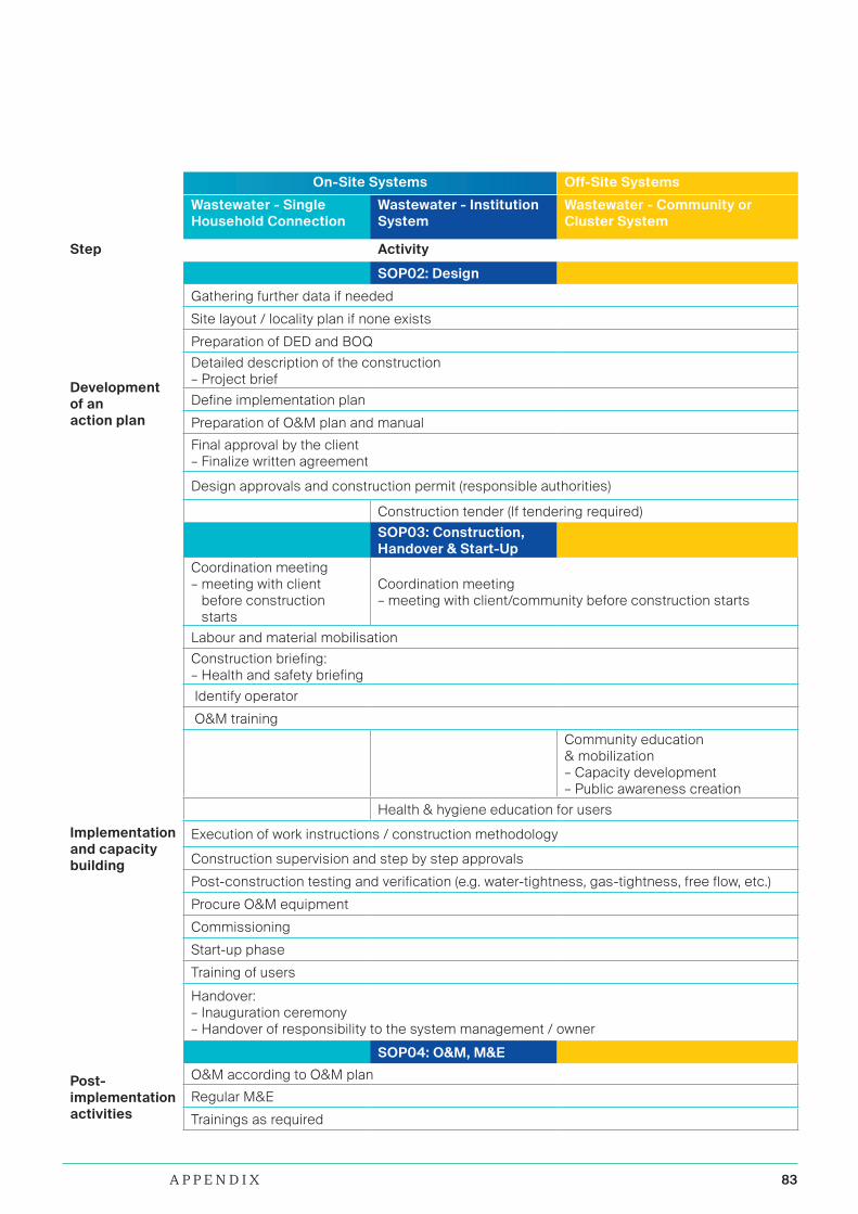
83A P P E N D I X
On-Site Systems Off-Site Systems
Wastewater - Single Household Connection
Wastewater - Institution System
Wastewater - Community or Cluster System
Step Activity
SOP02: Design
Development of an action plan
Gathering further data if needed
Site layout / locality plan if none exists
Preparation of DED and BOQ
Detailed description of the construction – Project brief
Define implementation plan
Preparation of O&M plan and manual
Final approval by the client – Finalize written agreement
Design approvals and construction permit (responsible authorities)
Construction tender (If tendering required)
SOP03: Construction, Handover & Start-Up
Implementation and capacity building
Coordination meeting – meeting with client
before construction starts
Coordination meeting – meeting with client/community before construction starts
Labour and material mobilisation
Construction briefing: – Health and safety briefing
Identify operator
O&M training
Community education & mobilization – Capacity development– Public awareness creation
Health & hygiene education for users
Execution of work instructions / construction methodology
Construction supervision and step by step approvals
Post-construction testing and verification (e.g. water-tightness, gas-tightness, free flow, etc.)
Procure O&M equipment
Commissioning
Start-up phase
Training of users
Handover: – Inauguration ceremony– Handover of responsibility to the system management / owner
SOP04: O&M, M&E
Post-implementation activities
O&M according to O&M plan
Regular M&E
Trainings as required

84
Monitoring and Evaluation (M&E) activities conducted on selected decentralised wastewater treatment projects throughout Tanzania
85I M P R I N T
Text Jutta Camargo Laura Bright-Davies Tim Fettback Modekai Sanga Dennis Wolter
Editing: Carol Haynes
Photos All rights reserved by BORDA
Layout gegenfeuer.net

86
BORDA AfricaRose Garden RoadPlot 312, MikocheniPO Box 105744Dar es SalaamTanzania