guidelines for standard urban storm water mitigation plan
TRANSCRIPT

Guidelines for the Standard Urban Storm Water Mitigation Plan
Storm Water Best Management Practices for New Development and Redevelopment
For the Santa Rosa Area and Unincorporated Areas around Petaluma and Sonoma
June 3, 2005
Sonoma County
City of Santa Rosa
Russian River Watershed Association
EOA, Inc. BKF Engineers

[This page intentionally left blank]

Acknowledgements
Acknowledgements
This document was prepared for the County of Sonoma, City of Santa Rosa and the Russian River Watershed Association. A Technical Advisory Committee was convened to provide input in the development of these guidelines and to review the draft document. We appreciate the effort and time afforded by the Technical Advisory Committee in providing comments, suggestions and guidance.
Agencies/Organizations Providing Representatives to the SUSMP Technical Advisory Committee Caltrans City of Santa Rosa Community Development Department City of Santa Rosa Public Works Department Consulting Engineers and Land Surveyors of California CSS Associates Architects, Inc. Engineering Contractors Association Homebuilders Association of Northern California Marin/Sonoma Mosquito and Vector Control District Quadriga Landscape Architecture and Planning, Inc. Regional Water Quality Control Board, Region 1 River Keeper Russian River Watershed Association Sonoma County Fire Services Sonoma County Permit and Resource Management Department Sonoma County Transportation and Public Works Department Sonoma County Water Agency
SUSMP Guidelines i

[This page intentionally left blank]

Table of Contents
Table of Contents
Page No.
ACKNOWLEDGEMENTS................................................................................................. i
ACRONYMS, ABBREVIATIONS AND DEFINITIONS .................................................v
CHAPTER 1: INTRODUCTION AND OVERVIEW .............................................. 1-1 1.1 Introduction.............................................................................................. 1-1 1.2 Background on SUSMP........................................................................... 1-1 1.3 Applicable Projects .................................................................................. 1-3 1.4 Storm Water Mitigation Plan ................................................................... 1-7 1.5 Source and Treatment Control Requirements.......................................... 1-7 1.6 Maintenance of Source and Treatment Controls ..................................... 1-7 1.7 Overview and Challenges to Controlling Storm
Water Pollutants and Flows ..................................................................... 1-8 1.8 Costs......................................................................................................... 1-9 1.9 Construction Sediment and Erosion Control ......................................... 1-10 1.10 Non-Compliance .................................................................................... 1-11
CHAPTER 2: STORM WATER MITIGATION PLAN .......................................... 2-1 2.1 Summary of SUSMP Requirements ........................................................ 2-1 2.2 Preparing the Preliminary Plan ................................................................ 2-2 2.3 Preparing the Final Plan......................................................................... 2-10 2.4 Written Certification of BMP Installation ............................................. 2-12
Attachment 2-1: Project Description Worksheet Attachment 2-2: Impervious Surface Worksheet Attachment 2-3: Proximity Worksheet Attachment 2-4: Pollutants of Concern Worksheet
CHAPTER 3: SOURCE CONTROLS ....................................................................... 3-1 3.1 Definitions and Purpose........................................................................... 3-1 3.2 Types of Pollutant Sources ...................................................................... 3-2 3.3 Regulatory Requirements......................................................................... 3-2 3.4 Source Control Principles ........................................................................ 3-3 3.5 Benefits to Using Source Controls........................................................... 3-4 3.6 Selecting Appropriate Source Controls ................................................... 3-5 3.7 Source Control Resources........................................................................ 3-8
SUSMP Guidelines ii

Table of Contents
Page No.
Attachment 3-1: Source Control BMP Checklist Attachment 3-2: Pervious Paving Fact Sheet
CHAPTER 4: TREATMENT CONTROLS 4.1 Definitions and Purpose........................................................................... 4-1 4.2 Selecting Treatment Controls .................................................................. 4-5 4.3 Hydraulic Sizing Design Criteria........................................................... 4-11 4.4 Technical Guidance on Design of Landscape-Based
Treatment Controls ................................................................................ 4-13 4.5 Limitations on Use of Infiltration Treatment Controls .......................... 4-50
Attachment 4-1: Evaluation of Storm Water Treatment Control BMPs Attachment 4-2: Storm Water Treatment Controls BMP Evaluation Matrix Attachment 4-3: Storm Water Treatment Control Design Guidelines
CHAPTER 5: MAINTENANCE OF SOURCE AND TREATMENT CONTROLS ........................................................................................... 5-1
5.1 Responsibility for Maintenance ............................................................... 5-1 5.2 Mechanisms to Assure Maintenance ....................................................... 5-2
Attachment 5-1: Example Source and Treatment Control Operation and Maintenance Inspection Annual Report
Attachment 5-2: Treatment Control Inspection Checklists
List of Tables
Table 1-1 Examples to Determine if a Project Meets SUSMP Applicability Criteria ............................................................................... 1-5 Table 1-2 Overview: Controlling Pollutants and Increased Flows
from New and Redevelopment Projects ................................................ 1-12 Table 4-1 Pollutants Listed as Impairing Local Creeks ........................................... 4-4 Table 4-2 Post-Construction Storm Water Treatment Control Categories and Descriptions....................................................................................... 4-6 Table 4-3 Applicability of Treatment Controls for Use in Sonoma County ............ 4-8 Table 4-4 Flow and Volume Based Treatment Control Designs ........................... 4-11
SUSMP Guidelines iii

Table of Contents
Page No.
List of Figures
Figure 1-1 Standard Urban Storm Water Mitigation Plan Boundary ...................... 1-13 Figure 2-1 Preliminary Storm Water Mitigation Plan Checklist ............................... 2-2 Figure 2-2 Final Storm Water Mitigation Plan Checklist........................................ 2-10 Figure 4-1 Vegetated Swale, Type 1 ....................................................................... 4-19 Figure 4-2 Vegetated Swale, Type 2 ....................................................................... 4-20 Figure 4-3 Bioretention – With Liner and Drain System ........................................ 4-24 Figure 4-4 Extended Detention Basin...................................................................... 4-29 Figure 4-5 Vegetated Buffer Strip ........................................................................... 4-33 Figure 4-6 Constructed Wetlands ............................................................................ 4-39 Figure 4-7 Wet Ponds .............................................................................................. 4-45 Figure 4-8 Modified Delaware Media Filter ........................................................... 4-49
REFERENCES ...............................................................................................................R-1
APPENDIX A: LANDSCAPING AND VEGETATION FOR BMPS......................... A-1
Santa Rosa Area iv

[This page intentionally left blank]

Acronyms, Abbreviations and Definitions
Acronyms, Abbreviations and Definitions
APN: Assessors Parcel Number
Bank Full Discharge: means discharge that fills a stable alluvial channel up to the elevation of the active flood plain. Field indicators can be used for estimating the elevation of the stage associated with bank full flow. In stable channels, bank full discharge corresponds closely with effective discharge, also known as “Channel-Forming Discharge”.
BASMAA: Bay Area Stormwater Management Agencies Association
Best Management Practice (BMP): means a program, technology, process, siting criteria, operational method, or engineered system, which when implemented prevents, controls, removes, or reduces pollution.
Channel-Forming Discharge: or “effective discharge” means the flow rate that transports the largest fraction of the sediment load over a period of years. For stable streams, the channel-forming discharge is considered equivalent to the “Bank Full Discharge”. The channel-forming discharge generally has a recurrence interval of 1.5 to 2 years.
Constructed Channel: means all waterways that are not in closed conduits and do not meet the definition of a “Natural Waterway” or “Modified Natural Waterway”. Constructed Channels also include landscaped constructed waterways. Constructed Channels do not include street gutters, roadside ditches, or drainage facilities installed in connection with the development of property.
CCRs: Conditions, Covenants and Restrictions
Development: means land disturbing activities; structural development, including construction or installation of a building or structure, creation of impervious surfaces; and improvements related to land subdivision.
DCIA: Directly connected impervious area
Directly Adjacent (City of Santa Rosa): means within a parcel of land that includes or is contiguous with a Natural Waterway, Modified Natural Waterway, or Constructed Channel.
Directly Adjacent (County of Sonoma): means within a parcel of land that includes or is contiguous with a Natural Waterway, Modified Natural Waterway, or Constructed Channel; and some portion of the development on said parcel must be within 100feet of the top of bank, and drainage from the development must flow towards and enter a waterway or channel.
SUSMP Guidelines v

Acronyms, Abbreviations and Definitions
Discretionary project: A project which requires the exercise of judgment or deliberation when a public agency or body decides to approve or disapprove a particular activity, as distinguished from situations where the agency or body merely has to determine whether there has been conformity with applicable statutes, ordinances, or regulations.1
Integrated Pest Management (IPM): A decision making process for managing pests that uses monitoring to determine pest-caused injury levels and determine the best methods for their control. IPM minimizes pesticide usage by using a combination of biological controls (e.g. natural predators), physical or mechanical controls (e.g. mowing), cultural controls (e.g., alternative plant type selection), and reduced risk chemical controls (e.g. soaps or oils). The IPM method uses the least hazardous pesticides only as a last resort for controlling pests.
Maximum Extent Practicable: refers to the technology based standard established by Congress in the Clean Water Act U.S.C. S 1342 (p)(3)(B)(iii) that municipal dischargers of storm water must meet. To achieve the maximum extent practicable standard, municipalities must employ whatever Best Management Practices (BMPs) are technically feasible (i.e., are likely to be effective) and are not cost prohibitive. The major emphasis is on technical feasibility. Reducing pollutants to the maximum extent practicable means choosing effective BMPs, and rejecting applicable BMPs only where other effective BMPs will serve the same purpose, or the BMPs would not be technically feasible, or the cost would be prohibitive.
Modified Natural Waterway: means any natural waterway that has been modified while retaining significant riparian vegetation, fish, wildlife habitat, and/or scenic values. Modified natural waterways do not include artificially created channels for storm waters, such as street gutters, roadside ditches, and drainage facilities including ditches installed in connection with the development of property.
Natural Waterway: means any natural stream of water flowing in a definite course or channel and possessing a bed and banks. It is not necessary that the flow of water be continuous throughout the year. Natural waterways do not include artificially created channels for storm waters, such as street gutters, roadside ditches, and drainage facilities installed in connection with the development of property.
NPDES: National Pollutant Discharge Elimination System
Reconstruction: means, on an already developed site, the replacement of existing impervious surface with new impervious surface. Reconstruction includes, but is not limited to the replacement of an existing structure with a new structure, or the replacement of existing impervious surface with new impervious surface that is not part of a routine maintenance activity. Examples of roadway reconstruction include: the addition of a through lane, significant change in horizontal and/or vertical alignment, or replacement of an entire bridge or the major parts of an existing bridge (in such a manner that it is effectively a new bridge) on new
1 California Secretary of Resources, September 7, 2004.
Santa Rosa Area vi

Acronyms, Abbreviations and Definitions
vertical or horizontal alignment.2 Excluded from this category are interior remodels and routine maintenance or repair. Excluded routine maintenance and repair includes roof or exterior surface replacement, pavement resurfacing, repaving and road pavement structural section rehabilitation within the existing footprint, and any other reconstruction work within a public street or road right-of-way where both sides of that right-of-way are developed.
Redevelopment: means, on an already developed site, the creation or addition of impervious surface. Redevelopment includes, but is not limited to: the expansion of a building footprint or addition or replacement of a structure; structural development including an increase in gross floor area and/or exterior construction or remodeling; replacement of impervious surface that is not part of a routine maintenance activity; and land disturbing activities related with structural or impervious surfaces.
Riparian Area: means the area between a stream or other body of water and the adjacent upland identified by soil characteristics and distinctive vegetation. It includes wetlands and those portions of floodplains and valley bottoms that support riparian vegetation.3 This vegetation is an associate of plant species which grows adjacent to freshwater watercourses, including perennial and intermittent streams, lakes and other bodies of fresh water. Riparian plant species and wetland plant species either require or tolerate a higher level of soil moisture than dryer upland vegetation, and are therefore generally considered hydrophytic. However, riparian vegetation may be distinguished from wetland vegetation by the different kinds of plant species.4
Road Maintenance and Repair: means, on existing roadways, all work that does not fall under the definition of reconstruction and does not result in the creation of new impervious surface. Such projects include but are not limited to: pavement and structure rehabilitation projects; operational improvement projects such as signing, striping, changeable message signs, signalization, and ramp metering; environmental mitigation projects such as landscaping and noise barriers; and storm damage and emergency repair projects.5
Roadside Ditch: means a constructed open channel paralleling a roadway embankment within the limits of the roadway right-of-way. Its primary function is to collect runoff from the roadway and areas adjacent to the right-of-way and to transport this accumulated water to an acceptable outlet point. A secondary function of a roadside ditch is to drain the base of the roadway to prevent saturation and loss of support for the pavement.6
RWQCB: Regional Water Quality Control Board
Source Control: means a site planning approach, a constructed component of a development project, or an operational activity that is included as part of a
2 Adapted from Caltrans, July 1, 1999. 3 California Department of Fish and Game, February 1998. 4 California Coastal Commission, February 1981. 5 Adapted from Caltrans, July 1, 1999. 6 Adapted from Illinois Department of Transportation, Division of Highways, April 2005.
SUSMP Guidelines vii

Acronyms, Abbreviations and Definitions
development project for the purpose of either 1) preventing pollutants from contacting storm water, or 2) reducing the quantity of runoff that drains from a developed site to the storm drain system. Examples of source controls include site designs that reduce impervious surfaces, trash storage enclosures, connections to the sanitary sewer system for non-storm water discharges, street sweeping, and the regular inspection and cleaning of storm drain inlets.
Storm Water Pollution Prevention Plan (SWPPP): The Statewide Construction Activity NPDES General Permit requires the preparation of a SWPPP for projects that disturb one acre or more. A SWPPP focuses on construction-period BMPs to reduce pollutants in storm water and reduce storm water quantity during construction.
SUSMP: Standard Urban Storm Water Mitigation Plan
SWRCB: State Water Resources Control Board
Top of Bank: means the points in a cross-section where the stream channel makes a transition to flood plain. Top of bank can be identified by a change in the slope of the land, a transition from terrestrial to riparian vegetation, and changes in the composition of substrate materials.
Treatment: means the application of engineered systems that use physical, chemical, or biological processes to remove pollutants.
Treatment Control: means an engineered system that is designed to remove pollutants from storm water using physical, chemical, or biological processes before the storm water is discharged to the storm drain system. Examples of treatment controls include vegetated swales, extended detention basins, vegetated buffer strips, bioretention areas, and media filters.
U.S. EPA: United States Environmental Protection Agency
WDRs: Waste Discharge Requirements
Wetlands – means those areas that are inundated or saturated by surface or ground water at a frequency and duration sufficient to support, and that under normal circumstances do support, a prevalence of vegetation typically adapted for life in saturated soil conditions. Wetlands generally include swamps, marshes, and bogs. For official determination whether or not an area is classified as a wetland pursuant to Section 404 of the federal Clean Water Act, contact the Army Corps of Engineers.
Santa Rosa Area viii

Chapter 1: Introduction and Overview
1 Introduction and Overview
1.1 Introduction
These guidelines have been developed to assist project sponsors and municipal staff to implement the Santa Rosa Area Standard Urban Storm Water Mitigation Plan (SUSMP) requirements that were adopted by the North Coast Regional Water Quality Control Board in June 2003. Since the SUSMP requirements apply to both privately sponsored projects and public capital improvement projects, these Guidelines should be used by development project applicants, municipal development project review staff, and municipal staff responsible for capital improvement projects. The SUSMP requirements are part of the Storm Water Management Plan that has become an enforceable part of the reissued municipal storm water National Pollutant Discharge Elimination System (NPDES) permit for the City of Santa Rosa, the County of Sonoma, and the Sonoma County Water Agency.
These guidelines also have been created to comply with the municipal storm water NPDES permit requirement for the City of Santa Rosa and County of Sonoma to develop a SUSMP Guidance Document.
1.2 Background on the SUSMP
The SUSMP was developed by the City of Santa Rosa and County of Sonoma to describe their programs for preventing and controlling the detrimental effects of new and redevelopment projects on storm water quality and runoff. All large municipalities in the State of California are currently required to meet similar requirements to limit the adverse impacts of development on storm water quality and hydrology.
The types of problems associated with storm water runoff in urban and urbanizing areas include increased concentrations of pollutants, with increased flow rates and durations that can cause
…… TThheessee GGuuiiddeelliinneess sshhoouulldd bbee uusseedd bbyy ddeevveellooppmmeenntt pprroojjeecctt aapppplliiccaannttss,, mmuunniicciippaall ddeevveellooppmmeenntt pprroojjeecctt rreevviieeww ssttaaffff,, aanndd mmuunniicciippaall ssttaaffff rreessppoonnssiibbllee ffoorr ccaappiittaall iimmpprroovveemmeenntt pprroojjeeccttss..
SUSMP Guidelines 1-1

Chapter 1: Introduction and Overview
BBeesstt mmaannaaggeemmeenntt pprraaccttiicceess ((BBMMPPss)) aarree mmeetthhooddss uusseedd ttoo mmiinniimmiizzee ppoolllluuttaannttss iinn ssttoorrmm wwaatteerr aanndd tthhee qquuaannttiittyy ooff ssttoorrmm wwaatteerr rruunnooffff..
creek channel erosion and scouring. U.S. EPA has found that development-induced increases in pollutants and in the flow and duration of runoff contribute to loss of habitat and decreases in aquatic biological diversity (U.S. EPA 1983).
1.2.1 Goals
The SUSMP’s goals for new and redevelopment projects are to manage, as close to the point of origin as possible, 1) storm water quality, 2) storm water quantity, and 3) to conserve natural areas of the development site. These three goals are described further below. It should be noted that the concept of “maximum extent practical” (MEP)1 applies to each of the goals.
Storm Water Quality. The first goal is to prevent pollutants generated at development and redevelopment projects from reaching storm drains. Projects covered by the SUSMP must be designed to minimize the introduction of pollutants.
Storm Water Quantity. The second goal is to prevent increases in storm water runoff from the two-year 24 hour storm event for Sonoma County. SUSMP projects should incorporate best management practices to limit the post-development runoff to pre-development conditions to the MEP. Best management practices are methods used to minimize pollutants in storm water and the quantity of runoff. One of the objectives of these guidelines is to provide more specific information about how MEP will be achieved.
Conserve Natural Areas. The third goal is to conserve natural areas of a development site. This goal supports the other two goals by preserving areas where storm water runoff can be purified naturally by infiltration into the soil and flow over vegetated areas. SUSMP projects should strive to maximize the amount of land left in a natural, undisturbed condition, preserve riparian areas and wetlands, limit clearing of native vegetation, and maximize trees and vegetation.
1 SUSMP definition: “Maximum Extent Practicable” (MEP) refers to the technology based standard established by Congress in the Clean Water Act U.S.C. S 1342 (p)(3)(B)(iii) that municipal dischargers of storm water must meet. To achieve the maximum extent practicable standard, municipalities must employ whatever Best Management Practices (BMPs) are technically feasible (i.e., are likely to be effective) and are not cost prohibitive. The major emphasis is on technical feasibility. Reducing pollutants to the maximum extent practicable means choosing effective BMPs, and rejecting applicable BMPs only where other effective BMPs will serve the same purpose, or the BMPs would not be technically feasible, or the cost would be prohibitive.
Santa Rosa Area 1-2

Chapter 1: Introduction and Overview
1.2.2 Geographic Areas Covered by the SUSMP SSoouurrccee ccoonnttrrooll The SUSMP applies to projects within the area covered by the storm water permit boundary as shown in Figure 1-1. In addition, these SUSMP guidelines apply to the unincorporated and urbanized areas surrounding the Cities of Petaluma and Sonoma, which are also shown in Figure 1-1. The SUSMP does not apply to the cities of Healdsburg, Windsor, Sebastopol, Rohnert Park, Cotati, Petaluma and Sonoma.
1.3 Applicable Projects
The SUSMP identifies the following four categories of new development and significant redevelopment projects that are required to design and implement source control and treatment control BMPs2 . This SUSMP applies to applicable projects that require a discretionary3 permit, including any ministerial permits that are based on the discretionary permit. Source controls will be recommended for all discretionary projects.
a) Development projects that create one acre (43,560 square feet) or more of new impervious surface. This category includes development of any type on public or private land, which falls under the planning and building authority of Sonoma County or City of Santa Rosa, where one acre or more of new impervious surface4, collectively over the entire project site, will be created. Project phasing5 to decrease impervious
2 Source control and treatment control BMPs are intended to reduce runoff and keep pollutants out of storm water throughout the life of the project. They may be described as post-construction BMPs or “post-development” control measures (Provision 27 of the SRA NPDES permit). Post-construction BMPs differ from construction BMPs, which are used during the construction phase to prevent erosion and keep construction-related pollutants from reaching storm water. 3 A “discretionary project” is a project which requires the exercise of judgment or deliberation when a public agency or body decides to approve or disapprove a particular activity, as distinguished from situations where the agency or body merely has to determine whether there has been conformity with applicable statutes, ordinances, or regulations. Examples of discretionary projects include projects that require design review, a conditional use permit, or approval of a tract map.4 The NPDES permit defines impervious surface as “all areas where improvements result in a ground surface that significantly limits natural percolation rates including, but not limited to, asphalt, cement, pavers, buildings, and plastic liners that are associated with the project.” 5 New development or redevelopment activity that is part of a larger common plan of development that results in less than one acre of impervious surface must comply with SUSMP requirements. (For example, if 50% of a subdivision is constructed and results in 0.9 acre of impervious surface and the remaining 50%
aanndd ttrreeaattmmeenntt ccoonnttrrooll BBMMPPss aarree iinntteennddeedd ttoo rreedduuccee rruunnooffff aanndd kkeeeepp ppoolllluuttaannttss oouutt ooff ssttoorrmm wwaatteerr tthhrroouugghhoouutt tthhee lliiffee ooff tthhee pprroojjeecctt.. TThheeyy mmaayy bbee ddeessccrriibbeedd aass ppoosstt--ccoonnssttrruuccttiioonn BBMMPPss......
SUSMP Guidelines 1-3

Chapter 1: Introduction and Overview
GGuuiiddaannccee iinn ddeetteerrmmiinniinngg wwhheetthheerr aa pprroojjeecctt iiss aa SSUUSSMMPP aapppplliiccaabbllee pprroojjeecctt iiss pprroovviiddeedd iinn CChhaapptteerr 22..
surface area shall not exempt the project from SUSMP requirements.
b) Streets, roads, highways and freeways that create one acre (43,560 square feet) or more of new impervious surface. This category includes any newly constructed impervious surface used for the transportation of pedestrians, bicycles, and motorized vehicles.
c) Redevelopment projects that are located on an already developed site and result in the addition of and/or reconstruction of one acre (43,560 square feet) or more of new impervious surface. Only the additional and/or reconstructed portion(s) of the site must be included in treatment design. Excluded from this category are interior remodels and routine maintenance or repair, including roof or exterior surface replacement and resurfacing.
d) Development and redevelopment projects located directly adjacent to a natural waterway, modified natural waterway, or constructed channel or that require a new storm drain outfall to such waterway6, regardless of project size or impervious surface. This requirement is intended to protect environmentally sensitive areas. For redevelopment projects, excluded from this category are interior remodels and routine maintenance or repair, including roof or exterior surface replacement and resurfacing.
Table 1-1 shows examples of projects that would and would not be considered “applicable projects.” Guidance in determining whether a project is a SUSMP applicable project is provided in Chapter 2. This guidance includes a form titled “Development and Building Application Information: Impervious Surface Worksheet” (Attachment 2-2).
of the subdivision is to be developed at a future date, the property owner must comply with SUSMP requirements.) 6 The terms, “natural waterway,” “modified natural waterway,” and “constructed channel” are defined in the Sonoma County Water Agency’s Flood Control Design Criteria and are included in the Acronyms, Abbreviations, and Definitions section of these guidelines.
Santa Rosa Area 1-4

Chapter 1: Introduction and Overview
Table 1-1
Examples to Determine if a Project Meets SUSMP Applicability Criteria
Project Type Area of Area of Impervious Surface Type of Water New Storm Applicable project? Project Site Body or Channel Drain Outfall Governing criteria
8(disturbed Directly Adjacent7 (if any) Redevelopment9New area)
Parking lot 1.5 acres
Parking lot 1.5 acres
Pedestrian and 3 acres bicycle trail
Urban infill 2 acres
Urban infill 2 acres
Urban infill 2 acres
Maintenance 1.1 acres
1.1 acres
0.9 acres
1.1 acres
1.1 acres
None
0.5 acres
None
None
None
None
None
Reconstruction of 1.1 acres
Reconstruction of 0.5 acres
Resurface 1.1 acres of parking
lot
None
None
None
None
None
None
None
None
None
None
None
None
None
None
Yes a) !�1 acre of new impervious surface
No a) ��1 acre of new impervious surface. Consider
source controls.
Yes b) !�1 acre of new impervious surface�
Yes a) !�1 acre of new impervious surface
Yes c) !�1 acre of new impervious surface
Yes c) !�1 acre of new impervious surface
No Resurfacing existing roadway excluded from new
impervious surface area. Consider source controls.
7 Directly Adjacent (City of Santa Rosa): means within a parcel of land that includes or is contiguous with a Natural Waterway, Modified Natural Waterway, or Constructed Channel. Directly Adjacent (County of Sonoma): means within a parcel of land that includes or is contiguous with a Natural Waterway, Modified Natural Waterway, or Constructed Channel; and some portion of the development on said parcel must be within 100-feet of the top of bank, and drainage from the development must flow towards and enter a waterway or channel. 8 Development means land disturbing activities; structural development, including construction or installation of a building or structure, creation of impervious surfaces; and improvements related to land subdivision. 9 Redevelopment means, on an already developed site, the creation and/or addition of impervious surface. Redevelopment includes, but is not limited to: the expansion of a building footprint or addition or replacement of a structure; structural development including an increase in gross floor area and/or exterior construction or remodeling; replacement of impervious surface that is not part of a routine maintenance activity; and land disturbing activities related with structural or impervious surfaces (SUSMP, 2002).
SUSMP Guidelines 1-5

Chapter 1: Introduction and Overview
Table 1-1 Examples to Determine if a Project Meets SUSMP Applicability Criteria
Project Type Area of Project Site (disturbed
area)
Area of Impervious Surface
New 8 Redevelopment9
Type of Water Body or Channel Directly Adjacent7
New Storm Drain Outfall
(if any)
Applicable project? Governing criteria
One single family residential home
10,000 s.f. 4,000 s.f. None Constructed channel
None Yes d) Adjacent to a constructed channel
Multifamily residence (duplex)
10,000 s.f. 4,000 s.f. None None None No Consider source controls.
Multifamily residence (duplex)
10,000 s.f. 4,000 s.f. None None Yes Yes d)�New storm drain outfall to a waterway
Multifamily residence (duplex)
10,000 s.f. 4,000 s.f. None None Yes No d) New storm drain outfall to a roadside ditch.
Consider source controls.
Tract Map: residential subdivision
15 acres 8 acres None Constructed channel
Yes Yes a) 1 acre of impervious surface, b) 1 acre of new
road, d) adjacent to a constructed channel, and d) new storm drain outfall
Santa Rosa Area 1-6

Chapter 1: Introduction and Overview
1.4 Storm Water Mitigation Plan
For applicable projects, the SUSMP requires the preparation and submittal of a preliminary Storm Water Mitigation Plan, final Storm Water Mitigation Plan and Written Certification of BMPs Installation during the project approval process. The Storm Water Mitigation Plan must provide specific required information regarding the post-construction BMPs that will be incorporated in the project to mitigate pollutants. The Written Certification of BMPs is a document verifying that the BMPs were installed as intended by the designer and/or as recommended by the manufacturer. Chapter 2 of these guidelines explains the specific requirements for each of these documents and offers step-by-step guidance in their preparation.
1.5 Source and Treatment Control Requirements
The SUSMP recognizes two types of post-development BMPs for storm water pollution control – source controls and treatment controls. Source controls include BMPs that are designed to prevent pollutants from reaching storm water runoff and minimize site runoff. Source controls include a large variety of BMPs that range from minimizing the amount of impervious surface used at a project site to specific pollution prevention BMPs such as providing a roof over waste storage areas. The municipal storm water NPDES permit characterizes source control as the first line of defense at a project site and storm water treatment as a backup or additional line of defense. Source controls will be recommended for all discretionary projects. Source controls are described in more detail in Chapter 3.
Storm water treatment controls are engineered systems that are designed to remove pollutants from storm water. The SUSMP and NPDES permit have specific hydraulic design criteria for sizing storm water treatment controls to assure that an optimum amount of storm water receives treatment. Examples of storm water treatment controls include vegetated swales, extended detention basins, and bioretention areas. These are described in more detail in Chapter 4.
1.6 Maintenance of Source and Treatment Controls
Source and treatment controls require long-term maintenance to continue to function effectively and avoid the creation of nuisance
TThhee SSttoorrmm WWaatteerr MMiittiiggaattiioonn PPllaann mmuusstt pprroovviiddee ssppeecciiffiicc rreeqquuiirreedd iinnffoorrmmaattiioonn rreeggaarrddiinngg tthhee ppoosstt--ccoonnssttrruuccttiioonn BBMMPPss tthhaatt wwiillll bbee iinnccoorrppoorraatteedd iinn tthhee pprroojjeecctt ttoo mmiittiiggaattee ppoolllluuttaannttss..
SUSMP Guidelines 1-7

Chapter 1: Introduction and Overview
TThhee SSUUSSMMPP rreeqquuiirreess tthhee pprroojjeecctt aapppplliiccaanntt ttoo pprroovviiddee ttoo tthhee CCiittyy oorr CCoouunnttyy aa ssiiggnneedd ssttaatteemmeenntt aacccceeppttiinngg rreessppoonnssiibbiilliittyy ffoorr mmaaiinntteennaannccee …… ..
conditions. The SUSMP requires the project applicant to provide to the City or County a signed statement accepting responsibility for maintenance until the responsibility is legally transferred. The SUSMP further requires property owners to conduct maintenance inspection of all source and treatment control BMPs at least once a year or as specified by the designer or manufacturer. Chapter 5 describes the requirements for ongoing source and treatment control maintenance.
1.7 Overview and Challenges to Controlling Storm Water Pollutants and Flows
As described previously, the SUSMP and municipal storm water NPDES permit require using source control and treatment control BMPs at applicable projects. In addition, all source and treatment controls that are implemented must be maintained to be effective. Table 1-2 provides a conceptual overview and examples of how these two types of BMPs and their maintenance accomplish the SUSMP’s goals related to water quality and conservation of natural areas. This table also shows how these guidelines are organized to provide a comprehensive and integrated approach to managing storm water.
1.7.1 Maximum Extent Practicable
One of challenges in implementing the SUSMP is to define what constitutes maximum extent practicable (MEP). These guidelines provide details about what constitutes MEP for purposes of meeting the SUSMP. What is considered to be MEP will continue to evolve based on national, statewide and local experience.
1.7.2 Balancing Prescriptiveness and Flexibility
These guidelines seek to strike a balance between providing detailed requirements and allowing site designers flexibility to design projects on diverse sites that will achieve the SUSMP’s goals. Given the evolving nature of what is considered MEP, it is possible that future NPDES permit reissuances, SUSMPs, and guidelines may become more prescriptive.
1.7.3 Selection of BMPs
To promote greater familiarity with source and treatment controls, these guidelines include pictures with examples of BMP use and references where more information may be found. As hands on familiarity with BMPs grows, municipal staff and project sponsors
Santa Rosa Area 1-8

Chapter 1: Introduction and Overview
should become increasingly knowledgeable and adept at using a variety of BMPs.
1.7.4 Channel-Forming Discharge
Urban development can increase the total volume of storm water discharged, duration of elevated flows, and runoff flow rates. During urban development, natural vegetated pervious ground surfaces may be converted to impervious surfaces such as paved highways, streets, rooftops, and parking lots.
The runoff leaving a newly developed urban area may be significantly greater than pre-development runoff from the same area. The cumulative increase in off-site runoff may cause downstream erosion and flooding, which can subsequently increase sediment loads to the entire storm water conveyance system.
One goal of the SUSMP is to prevent increases in storm water runoff from the two-year 24 hour storm event. For SUSMP applicable projects, the applicant is responsible for demonstrating that the post-development runoff from the project site will be limited to the pre-development runoff conditions as described in more detail in Chapter 2 (Section 2.2 Step 5).
1.8 Costs
A number of the source controls described in Chapter 3 may be incorporated in a project at relatively low cost above the project’s baseline costs. In general, the earlier source controls are incorporated into the project design, the more economical they are to implement. By using site planning source controls that reduce a project’s total impervious area, a project applicant can reduce the amount of storm water that will require treatment and thereby reduce the size of treatment controls.
Treatment controls are generally more costly to construct and maintain than source controls. There are few reliable studies on costs, and the information on costs that is available varies depending on the type of treatment control and also based on the application of a particular treatment control to different situations.
Some examples of documented treatment control costs are available in work conducted by an independent third party review
IInn ggeenneerraall,, tthhee eeaarrlliieerr ssoouurrccee ccoonnttrroollss aarree iinnccoorrppoorraatteedd iinnttoo tthhee pprroojjeecctt ddeessiiggnn,, tthhee mmoorree eeccoonnoommiiccaall tthheeyy aarree ttoo iimmpplleemmeenntt..
SUSMP Guidelines 1-9

Chapter 1: Introduction and Overview
of costs for Caltrans10. The construction cost for vegetated swales ranged from median values of from about $12,000 (four nationwide sites) per acre contributing area to $90,000 (six Caltrans sites). The construction costs for extended detention basins ranged from about $4,000 (twenty-three nationwide sites) per acre contributing area to $63,000 (five Caltrans sites). Lastly, the median construction costs for bioretention areas was about $46,000 (two nationwide sites) per acre contributing area. It is expected that local costs for vegetated swales and extended detention basins would fall within these ranges and that the Caltrans costs are at the high end because of the unique aspects of its BMP Retrofit Pilot Study. The construction costs for various types of subsurface storm water filtering systems were greater than $100,000 per acre contributing area.
The maintenance costs of treatment controls are commonly expressed as a percentage of the construction costs. Most treatment controls are reported to cost between 3 to 5% of the construction costs to maintain each year. The little data available on the maintenance of vegetated swales suggests that the annual maintenance costs would be more in the range of about 1% of the construction costs.
1.9 Post-Construction Sediment and Erosion Control
Sediment is an important pollutant of concern in the North Coast Region. During construction sediment and erosion control BMPs must be implemented in accordance with the Statewide Construction Activity NPDES General Permit and the City of Santa Rosa or County of Sonoma grading permit programs. The design of projects must also consider potential sedimentation and erosion issues during long-term project operations and incorporate appropriate sediment and erosion controls in the project design.
Chapter 3, Source Controls, emphasizes the need to select and maintain vegetation in landscaped pervious areas to prevent runoff from contacting bare earth and conveying sediment into the storm drain system. Similarly, pervious paving materials must also be selected, designed and maintained to avoid sedimentation and erosion.
10 Caltrans. 2001. Draft Third Party Best Management Practice Retrofit Pilot Study Cost Review.
1-10 Santa Rosa Area

Chapter 1: Introduction and Overview
1.10 Non-Compliance
The Santa Rosa Area municipal storm water NPDES permit requires the City of Santa Rosa, County of Sonoma and Sonoma County Water Agency to implement legal authority to control pollutant discharges to their respective storm drain systems. At a minimum, this legal authority empowers the agencies to use enforcement mechanisms, including monetary fines, to require compliance by private entities within their jurisdictions. In the event that a project applicant fails to comply with the SUSMP requirements, the City or County may determine that it is necessary to undertake enforcement actions, which may include a monetary fine.
IInn tthhee eevveenntt tthhaatt aa pprroojjeecctt aapppplliiccaanntt ffaaiillss ttoo ccoommppllyy wwiitthh tthhee SSUUSSMMPP rreeqquuiirreemmeennttss,, tthhee CCiittyy oorr CCoouunnttyy mmaayy ddeetteerrmmiinnee tthhaatt iitt iiss nneecceessssaarryy ttoo uunnddeerrttaakkee eennffoorrcceemmeenntt aaccttiioonnss,, wwhhiicchh mmaayy iinncclluuddee aa mmoonneettaarryy ffiinnee..
SUSMP Guidelines 1-11

Chapter 1: Introduction and Overview
Table 1-2 Overview: Controlling Pollutants and Increased Flows from New and Redevelopment Projects Actions to Accomplish
SUSMP & NPDES Permit Goals
Examples of Source Control BMPs (Chapter 3)
Examples of Treatment Control BMPs (Chapter 4)
Maintenance of Source and Treatment Controls
(Chapter 5) 1. Mimic and/or retain
natural absorption and purification of storm water by soil and surface vegetation
1) Minimize impervious surfaces. 2) Minimize directly connected impervious
surfaces, such as by connecting roof downspouts to vegetated areas.
3) Use small detention areas throughout project site.
4) Assure that any source controls that detain water are designed to drain completely within 72 hours after rainfall has ended to minimize mosquito breeding.
1) Use landscape-based treatment controls as a first choice.
2) Design landscape within treatment controls to minimize use of fertilizers and pesticides.
3) Where soils and other conditions allow, use infiltration type treatment controls
1) Assure that planned pervious areas are not converted to impervious areas.
2) Maintain vegetation within vegetated source and treatment controls.
2. Prevent erosion in creek channels
5) All of above. 6) Decrease runoff by using pervious
pavements. 7) Use bioengineering to stabilize and
restore creek channels.
4) All of above. 5) Where feasible, use treatment controls
that detain storm water. 6) Follow recommendations for selecting
and designing treatment controls to minimize mosquito breeding.
7) Provide Marin-Sonoma Vector Control staff with access to treatment controls that contain water for more than 72 hrs.
3) Assure continued perviousness of soils in landscaped areas used as source and treatment controls.
3. Protect sensitive aquatic areas
8) All of above 9) Provide setback, buffers between project
and creeks and/or wetlands.
8) Locate treatment controls as close to the point of pollutant origin as possible.
9) Do not use waters of the state, such as creeks and wetlands to treat storm water.
4) Perform sufficient maintenance of treatment controls to maintain the distinction between a treatment control and an aquatic habitat, which has additional requirements.
4. Prevent increases in pollutants to creeks, especially pollutants listed as impairing local creeks
10) Design landscape to minimize use of fertilizers and pesticides.
11) Minimize disturbance of steep, erodable slopes.
12) Assure that post-construction project specific activities that generate pollutants are controlled by source controls (for example, roofing outdoor storage areas).
10) Select treatment controls that will treat pollutants of concern, such as sediment and nutrients.
11) Use the SUSMP’s guidance sheets to design treatment controls.
12) Design treatment control vegetation to minimize use of fertilizers and pesticides.
5) Maintain type of landscape that minimizes need to use fertilizers and pesticides.
6) Assure maintenance of source control BMPs to minimize project specific pollutants, such as from washwaters.
7) Assure continued use of operational BMPs during life of project.
5. Prevent the discharge of non-storm water discharges to storm drain system
13) Implement No. 11 above. 14) Design landscaping to conserve water
and minimize irrigation runoff
13) Design treatment controls to eliminate need for any prohibited, non-storm water discharges to the storm drain.
8) Make sure that maintenance activities do not result in any prohibited non-storm water discharges to storm drain.
1-12 Santa Rosa Area

F
·|}þ12
·|}þ128
·|}þ116
·|}þ121
·|}þ116
£¤101
SANTA ROSA
PETALUMA
WINDSOR
ROHNERT PARK
SONOMA
HEALDSBURG
COTATI
SEBASTOPOL
Mark West Creek
Russian River
Sa nt a R os a C r e e k
Dry Creek
R IVER RD
ADOBE RD
DST
AV
AR
NO
LDD
R
WESTS IDE RD
BODEGA AV
OCCIDENTAL RD
FULT
ON
RD
PINER RD
ROBLAR RD
PETALU
MA
HILLR
D
NAPA RD
PEPPER RD
EAST
SID
E
RD
GUERNEVILLE RD
BODEGA
HWY TODD RD
LLANORD
GRATON
RD
PETALUMA VLY ORD RD
HALL RD
MARK WEST SPRINGS RD
BENNETT VALLEY RD
STO
NY
POIN
T
RD
SAINT HELENA RD.
SONOMA MTN RD
RIEBLI RD C
ALISTOG
AR
D.
SNY
DE
RLN
ROBE
RTS
RD
SHILOH RD
ELY RD
RAM
AL R D
GRANGE RD
LAG
UN
AR
D
OLD
REDWOOD
HW
Y
LUDWIG AV FAUG
HT
RD
WARM SPRINGS RD
FREMONT DR
3RD ST
E COTATI AV
S ELY RD
SLU
SSE
R
RD
FRE IRD
MIDDLE TWO ROCK RD
LAKE
VILLE
RD
TOMALES RD
SAN
TA
RO
SA
AV
MIR
AB
ELR
D
N MCDOWELL BLVD
STEELE LN
LONE PINE RD
VERANO AV
Standard Urban Stormwater Mitigation Plan Boundary
Access restrictions and legal prerequisites for accessing the data set apply to assure the protection of privacy or intellectual property. Limitations on the data set including the copying, reproducing and /or transmitting of data by any means is prohibited without written permission from the Permit and Resource Management Department (PRMD), County of Sonoma, California.
Use constraints, restrictions and legal prerequisites for using the data set, after access is granted, include acknowledgment of this data as source. Access constraints applied to assure the protection of privacy or intellectual property. Technical assistance is not provided to the consumer by the PRMD for the use of this data. Information about the distributor of and options for obtaining the data set are to be directed toward PRMD. All distributions of data are copyrighted by the County of Sonoma, California.
Map Scale and Reproduction methods limit precision in physical features displayed. This map is for illustrative purpose only, and is not suitable for parcel-specific decision making.
Legend
SUSMP Boundary
City Boundaries
Main Arterial Streets
Highways
Waterways
1:250,000
Ê0 52.5 Miles
Inset Map
Ê Not to Scale
SS oo n on o mm aa CC oo u nu n tt yy Permit and Resource Management Department
Author: PRMD 2550 Ventura Avenue, Santa Rosa, CA 95403Cartography: S.Mason File No.: r:prmd_base\\engineering\StandardUrbanStormwaterMitigationPlanBoundary.mxd 707-565-1900 FAX 707-565-1103Date: 03/28/2005
1-13 Figure 1-1 Santa Rosa Area

[This page intentionally left blank]

Chapter 2: Storm Water Mitigation Plan
2 Storm Water Mitigation Plan
This chapter explains the requirement for project applicants to include a written Storm Water Mitigation Plan (SWMP) in development permit applications that meet the SUSMP criteria described in Chapter 1. Following a summary of SUSMP requirements, step-by-step instructions are provided for preparing the preliminary and final Storm Water Mitigation Plan.
2.1 Summary of SUSMP Requirements
For applicable projects (as defined in Section 1.3), the SUSMP requires the preparation of a Preliminary Storm Water Mitigation Plan, Final Storm Water Mitigation Plan and a Written Certification of BMPs Installation. The SWMP requirements apply to both privately sponsored developments and publicly sponsored improvement projects that meet the SUSMP criteria. The SUSMP requirements for each of these items are described below.
The Preliminary Storm Water Mitigation Plan (preliminary Plan) is prepared and included as part of the project’s planning phase. For private projects, an adequate preliminary Plan must be submitted for a planning application to be considered complete. For public projects, the preliminary Plan is included with the preliminary design documents. The preliminary Plan is submitted simultaneously with the tentative map, preliminary site plan and/or landscaping plan. The required contents of the preliminary plan are described in Section 2.2.
The Final Storm Water Mitigation Plan (final Plan) must be included as part of public and/or subdivision improvement plans and/or building permit application, whichever occurs first. For public projects, the final Plan is prepared as part of the final design documents. The required contents of the final Plan are described in Section 2.3.
FFoorr pprriivvaattee pprroojjeeccttss,, aann aaddeeqquuaattee PPrreelliimmiinnaarryy SSttoorrmm WWaatteerr MMiittiiggaattiioonn PPllaann mmuusstt bbee ssuubbmmiitttteedd ffoorr aa ppllaannnniinngg aapppplliiccaattiioonn ttoo bbee ccoonnssiiddeerreedd ccoommpplleettee..
SUSMP Guidelines 2-1

Chapter 2: Storm Water Mitigation Plan
2.2 Preparing the Preliminary Plan
This section provides step-by-step instructions for preparing the required components of the preliminary Plan as listed in Figure 21.
Req
uire
d
Ade
quat
e
Provide the following written information:
Figure 2-1 PRELIMINARY STORM WATER MITIGATION PLAN
5 ��Project description
5 � Impervious surface and proximity worksheets
5 � Estimated pre- and post-development runoff calculations
5 � Identified pollutants of concern
5 � Types of BMPs selected to mitigate pollutants
5 � Types of BMPs selected to limit channel-forming discharges
5 � Preliminary treatment control BMP sizing
5 �� Waiver documents, if any
5 � Responsibility for BMP maintenance
UUssee tthhee PPrroojjeecctt DDeessccrriippttiioonn WWoorrkksshheeeett ((AAttttaacchhmmeenntt 22--11)) ttoo pprreeppaarree aa pprroojjeecctt ddeessccrriippttiioonn..
Req
uire
d
Adeq
uate
Show the following information on project drawings:
5 � Location and conceptual design of BMPs
D Step 1: Prepare Project Description
Use the Project Description Worksheet (Attachment 2-1) to prepare a project description. The worksheet includes:
� Site Plan � Assessor’s Parcel Number � Street address (if an address has been assigned) � Total area of site � Existing land use at the site � Detail regarding proposed land use activities (e.g.,
number of units of single family residential, number of units of multifamily residential, number of square feet of retail or office commercial, etc.)
Santa Rosa Area 2-2
Chapter 2: Storm Water Mitigation Plan
� Features of the project, or potential pollutant generating activities (activities of concern) proposed on the site, which may trigger source control requirements. A list of activities of concern is provided in the Project Description Worksheet (see item no. 13 on Attachment 2-1).
� Any hydrologic features on or adjacent to project site (e.g., wetlands, seeps, springs, natural waterways, modified natural waterways, or constructed channels)
� Any new storm drain outfall, to be constructed as part of the project, to a hydrologic feature, such as those listed above
� Name(s) of water body(ies) that will receive storm water flows from the project. Include both the immediate receiving water body, and water bodies farther downstream.
� Any sensitive natural features (e.g., riparian areas, wetlands, and steep slopes) on site that would be preserved. The project description must include the total square footage or acreage of sensitive natural features now existing and the square footage or acreage that would be preserved.
D Step 2: Prepare Impervious Surface and Proximity Worksheets
The Impervious Surface Worksheet and the Proximity Worksheet are used to confirm that a project is a SUSMP applicable project. The use of these worksheets is described below.
Impervious Surface Worksheet. Measure the amount of existing impervious surface on the site and use the conceptual or preliminary project plans to calculate the amount of impervious surface that would exist on the site at completion of the project.
If the project would create and/or reconstruct one acre or more of impervious surface, complete the Impervious Surface Form (Attachment 2-2) to document the amount of impervious surface. The applicant enters the square footage for the pre-development imperviousness, proposed new impervious surface, and any proposed area on which impervious surface would be reconstructed. The square footage of new and
TThhee IImmppeerrvviioouuss SSuurrffaaccee WWoorrkksshheeeett aanndd tthhee WWaatteerrwwaayy PPrrooxxiimmiittyy WWoorrkksshheeeett aarree uusseedd ttoo ccoonnffiirrmm tthhaatt aa pprroojjeecctt iiss aa SSUUSSMMPP aapppplliiccaabbllee pprroojjeecctt..
SUSMP Guidelines 2-3

TThhee IImmppeerrvviioouussSSuurrffaacceeWWoorrkksshheeeett aannddtthhee WWaatteerrwwaayyPPrrooxxiimmiittyyWWoorrkksshheeeett aarreeuusseedd ttoo ccoonnffiirrmmtthhaatt aa pprroojjeecctt iiss aaSSUUSSMMPPaapppplliiccaabblleepprroojjeecctt..
Chapter 2: Storm Water Mitigation Plan
reconstructed impervious surface are then added together. Calculations must be attached to the form.
Proximity Worksheet. The Proximity Worksheet (Attachment 2-3) is completed if the project is directly adjacent1 to a natural waterway, modified natural waterway, or constructed channel, or if the project requires a new storm drain outfall to one of these resources. Proximity may be determined by conducting a site visit, consulting USGS maps, parcel maps, and/or consulting City or County personnel.
On the Proximity Worksheet, indicate the name, or other identifier, of any natural waterway, modified natural waterway, or constructed channel to which the project is directly adjacent or to which the project will construct a new storm drain outfall. Applicants must include on the worksheet the method used to determine proximity, including any map reference.
Include the completed worksheets and imperviousness calculations in preliminary Plan. For projects that do not require a SWMP, attach worksheets and imperviousness calculations to the planning permit application, and use the Source Control Checklist to consider source control measures.
D Step 3: Estimate Pre- and Post- Development Runoff
Pre- and post-development runoff is calculated by a licensed civil engineer, architect, or landscape architect when a drainage plan is prepared. If a drainage plan is not required for a project, these calculations are prepared separately. Calculate pre- and post-development runoff. The calculations should be performed using the methods described in Chapter 4.
D Step 4: Identify Pollutants of Concern
Provision 30 of the municipal storm water NPDES permit states that the SUSMP “shall consider pollutants of concern or activities of concern in identifying appropriate BMPs for new development or significant redevelopment projects.” Applicants should refer to the Pollutants of Concern Worksheet (Attachment 2-4) to identify pollutants of concern that are anticipated to be generated by the proposed project. Identify Pollutants of Concern in the preliminary Plan.
1 For definitions of Directly Adjacent, Natural Waterway, Modified Natural Waterway and Constructed Channel, see the list of Acronyms, Abbreviations and Definitions.
Santa Rosa Area 2-4

Chapter 2: Storm Water Mitigation Plan
D Step 5: Evaluate Channel-Forming Discharge
In order to minimize downstream erosion and protect stream habitat, the project applicant shall provide runoff calculations for pre-development and post-development conditions. The pre- and post-development runoff calculations shall be based on the two-year 24 hour storm event for Sonoma County. This storm frequency has been selected for design purposes for mitigating the effects of channel-forming discharges.
The design shall then limit the post-development runoff flow rate and velocity to the pre-development discharge flow rate and velocity from the project site. BMPs intended to mitigate increases in the total volume of storm water discharged and increases in discharge duration shall also be considered. The City of Santa Rosa and the County of Sonoma are currently investigating and evaluating approaches to mitigate volume and duration increases. The City of Santa Rosa and the County of Sonoma are also evaluating areas within the permit boundary that may not be subject to quantity (flow rate or volume) considerations.
D Step 6: Select Source Control BMPs
Source control BMPs are relatively low-technology and in many cases low-cost practices that help keep pollutants out of storm water. Source controls are not intended to remove pollutants after they have entered storm water runoff. Source control BMPs must be selected to address specific activities or features that will be included in a project. Chapter 3 provides more detailed guidance on selecting appropriate source control BMPs.
To select source control BMPs that will be appropriate for a specific project, consult the Source Control Checklist, included as Attachment 3-1 of Chapter 3. The checklist identifies source control measures that apply to projects that contain specific project features (e.g., buildings, driveways, parking lots) or that will include specific activities (e.g., vehicle cleaning, food service, fuel dispensing). Use the checklist to identify the source controls that will apply to the features and activities proposed in your project and prepare a list of these source controls as a part of the preliminary SWMP.
SSoouurrccee ccoonnttrroollss aarree rreellaattiivveellyy llooww--tteecchhnnoollooggyy aanndd iinn mmaannyy ccaasseess llooww--ccoosstt pprraaccttiicceess tthhaatt hheellpp kkeeeepp ppoolllluuttaannttss oouutt ooff ssttoorrmm wwaatteerr..
SUSMP Guidelines 2-5

Chapter 2: Storm Water Mitigation Plan
TTrreeaattmmeenntt ccoonnttrroollss aarree eennggiinneeeerreedd ssyysstteemmss ddeessiiggnneedd ttoo rreemmoovvee ppoolllluuttaannttss ffrroomm ssttoorrmm wwaatteerr rruunnooffff bbeeffoorree iitt fflloowwss ooffffssiittee..
The project-specific list of source control BMPs needs to indicate which BMPs mitigate pollutants; which BMPs reduce the amount of pervious surfaces and thereby reduce the timing and amount of runoff; and which BMPs promote both of these objectives.
D Step 7: Select Treatment Control BMPs
Treatment control BMPs are engineered systems designed to remove pollutants from storm water runoff before it flows offsite. Treatment controls may be categorized as landscaped-based and non-landscaped based controls. Landscaped based controls include vegetated swales, wet ponds, constructed wetlands, and various other above-ground treatment controls. The non-landscape based controls are generally subsurface systems that rely on filtering of storm water through sand or other media, or sedimentation. Landscape-based treatment controls are more visible and believed to be better maintained than non-landscape based controls. Although landscape-based controls are generally preferred, they may not be practicable for projects on small urban sites.
Each applicable project must include treatment BMPs that are appropriate given the pollutants of concern, soil conditions, slope, and other constraints associated with each project site. A BMP that is appropriate to one project may not be appropriate to another. Chapter 4 provides detailed information regarding the various types of treatment controls and guidance in selecting appropriate BMPs based on specific project and site conditions.
Attachments 4-1 and 4-2 in Chapter 4 have been developed to assist the project applicant through the process of selecting appropriate treatment control BMPs for the project. City and County staff have determined that the treatment controls with the widest applicability for use in Sonoma County are vegetated swales, bioretention areas, extended detention basins and vegetated filter strips.
If landscape-based treatment controls are not used, the preliminary Plan must explain why non-landscaped based treatment controls are recommended. The project-specific list of treatment control BMPs needs to indicate which BMPs reduce pollutants; which BMPs reduce the timing and amount of runoff, and which BMPs promote both of these objectives.
Santa Rosa Area 2-6

Chapter 2: Storm Water Mitigation Plan
D Step 8: Locate BMPs and Prepare Conceptual Design
Prepare drawings that show the locations of proposed source control and treatment control BMPs on the sites. The location of certain source control measures will be dictated by other considerations. For example, the plumbing of interior floor drains to the sanitary sewer will occur at the location of the interior floor drain. Locating other source control measures, such as maximizing pervious areas will require careful consideration to identify the optimal areas to maintain perviousness on site. Some guidelines in locating source controls are provided below:
x Locate pervious areas between developed impervious areas and sensitive natural features (e.g., creeks, wetlands, steep slopes). This allows for infiltration and filtration before runoff reaches these natural features.
x Locate pervious areas downslope from developed impervious areas. This will allow for infiltration and filtration before runoff leaves the site.
x Fewer but larger pervious areas generally offer greater environmental benefit than a larger number of small pervious areas.
Considerations for identifying appropriate locations for treatment control BMPs are provided below:
x Locate treatment controls along the hydraulic grade line of the site’s drainage. This will allow for gravity to provide the drainage into and out of the treatment control and avoid the need for a pumped system. Pump systems are feasible and may result in only nominal added maintenance expense, but they can lead to mosquito control problems.
x Provide access for inspection of treatment controls. County or City officials and the Marin/Sonoma Mosquito and Vector Control District staff will need to be able to access treatment controls to verify maintenance and investigate problems. If the property will be subdivided, the BMP should be in a common accessible area.
x Provide access for maintenance equipment. Access requirements for maintenance vary with the type of
LLooccaattee ppeerrvviioouuss aarreeaass ddoowwnnssllooppee ffrroomm ddeevveellooppeedd iimmppeerrvviioouuss aarreeaass.. TThhiiss wwiillll aallllooww ffoorr iinnffiillttrraattiioonn aanndd ffiillttrraattiioonn bbeeffoorree rruunnooffff lleeaavveess tthhee ssiittee..
SUSMP Guidelines 2-7
Chapter 2: Storm Water Mitigation Plan
TTrreeaattmmeenntt ccoonnttrroollss aarree rreeqquuiirreedd ttoo ccoonnffoorrmm ttoo tthhee ddeessiiggnn gguuiiddaannccee pprroovviiddeedd iinn CChhaapptteerr 44..
treatment control selected. Wet ponds and extended detention basins typically require maintenance roads that can be used by heavy vehicles. Vegetated swales, bioretention areas, and vegetated filter strips typically require access by equipment used for landscape maintenance.
x Integrate the treatment controls with landscaping. This will make efficient use of the project site and promote aesthetic values. Zoning codes typically require building setbacks, buffer areas, and minimum open space allowances. It may be possible to locate a treatment control BMP in such an area.
After the locations have been selected, use the design guidance provided in Chapter 4’s fact sheets to prepare conceptual design of the treatment control BMPs. Detailed construction drawings are not required at this stage, but drawings, sketches, or descriptions should be included as needed to illustrate the proposed design and to support calculations. Treatment controls are required to conform to the design guidance provided in Chapter 4. Include in the preliminary Plan the drawings showing the location of source control and treatment control BMPs, and the conceptual design drawings for treatment controls.
D Step 9: Size Treatment Control BMPs
The size of a treatment control will depend on the size of the project area draining to the treatment control and the type of treatment control selected. Treatment controls should be sized to treat only the runoff from the project area.
Treatment controls can be categorized as “flow-based” or “volume-based” controls. Flow-based systems, such as vegetated swales, vegetated filter strips, and media filters remove pollutants from a moving stream of storm water runoff primarily by filtration, settling, flotation and infiltration. Volume-based systems detain storm water for periods of time, typically 48 to 72 hours, and treat storm water primarily through settling and infiltration.
After determining the size of the total project area contributing to the treatment control, applicants will need to use the runoff calculations prepared in Step 3 and the hydraulic sizing requirements provided in Section 4.3 to determine the appropriate size of treatment control BMPs. Hydraulic sizing
Santa Rosa Area 2-8

Chapter 2: Storm Water Mitigation Plan
requirements are provided for both flow-based and volume-based treatment controls. After completing the sizing calculations for treatment control BMPs, the calculations must be included in the preliminary Plan.
D Step 10: Waiver, If Applicable
A waiver may be granted when all appropriate treatment control BMPs have been considered and rejected as infeasible. If a waiver is granted the developer shall be required to pay an in lieu fee to the City or County. The amount of the fee shall be determined by the applicable municipality based on information provided by the applicant. This fee shall be placed in a fund designated for a specific project to be determined with the waiver documentation. The City and County are developing procedures for the waiver program.
Step 10 A:
If treatment controls are feasible then go to Step 11.
Step 10 B, Waiver Program:
If all treatment controls are determined to be infeasible then an applicant may request a waiver from SUSMP treatment and channel-forming discharge requirements for the project. A waiver application must be submitted to the City or County for consideration. The waiver application must document why treatment controls are infeasible for the project. The waiver application must also contain a dollar estimate of the work being waived. The dollar estimate shall include the cost of planning, designing, constructing, maintaining, and replacing the BMPs subject to the waiver application. Prior to a waiver being granted, the applicant shall pay an in lieu fee to the City or County in an amount equal to the approved dollar estimate. This fee shall be placed in a fund designated for a specific project identified by the applicant in the waiver document.
D Step 11: Assign Responsibility for Long-term Maintenance of BMPs
Review the guidance provided in Chapter 5 regarding the requirement to maintain source and treatment controls. A maintenance mechanism, such as a maintenance agreement or comparable document, will need to be included in the final Plan. For the preliminary Plan, it will be adequate to include a brief statement that identifies the individual or entity that will
AA wwaaiivveerr mmaayy bbee ggrraanntteedd wwhheenn aallll aapppprroopprriiaattee ttrreeaattmmeenntt ccoonnttrrooll BBMMPPss hhaavvee bbeeeenn ccoonnssiiddeerreedd aanndd rreejjeecctteedd aass iinnffeeaassiibbllee..
SUSMP Guidelines 2-9

Chapter 2: Storm Water Mitigation Plan
be responsible for long-term maintenance of the proposed source control and treatment controls. Include the maintenance statement in the preliminary Plan.
TThhee pprreelliimmiinnaarryy PPllaann iiss ssuubbmmiitttteedd aass aann aattttaacchhmmeenntt ttoo tthhee ppllaannnniinngg oorr bbuuiillddiinngg ppeerrmmiitt aapppplliiccaattiioonn..
D Step 12: Submit the Preliminary Plan
The preliminary Plan is submitted as an attachment to the planning or building permit application. Municipal staff will review the preliminary Plan as part of the application submittal and may request modifications during plan review. Storm water conditions of approval will apply when administering discretionary permits, including any ministerial permits that are based on the discretionary permit.
2.3 Preparing the Final Plan
The final Plan must be included as part of the public and/or subdivision improvement plans and/or building permit application, whichever occurs first. This section provides step-by-step instructions for preparing the required components of the preliminary Plan, which are shown in Figure 2-1.
TThhee ffiinnaall PPllaann mmuusstt bbee iinncclluuddeedd aass ppaarrtt ooff ppuubblliicc aanndd//oorr ssuubbddiivviissiioonn iimmpprroovveemmeenntt ppllaannss aanndd//oorr bbuuiillddiinngg ppeerrmmiitt aapppplliiccaattiioonn,, wwhhiicchheevveerr ooccccuurrss ffiirrsstt..
Req
uire
d
Ade
quat
e
Figure 2-2 FINAL STORM WATER MITIGATION PLAN CHECKLIST
Provide the following written information:
5 � Detailed hydraulic calculations identifying the sizing criteria for each storm water treatment control BMP based upon the anticipated flow and/or volume;
5 � Maintenance plan, including maintenance assurances and funding mechanism.
Req
uire
d
Ade
quat
e
Provide the following information on project drawings:
5 � Plan view of the project showing all storm water related source and treatment control BMPs.
� � The plan view may be included as part of the grading plan, site plan, other related plan, or on a separate plan sheet, included in the public improvement plans or building permit application.
5 � Construction details for each source and treatment control BMP
2-10 Santa Rosa Area

TThhee ffiinnaall PPllaanniiss ssuubbmmiitttteedd aassaann aattttaacchhmmeennttttoo tthheessuubbddiivviissiioonniimmpprroovveemmeennttppllaann aanndd//oorrbbuuiillddiinngg ppeerrmmiittaapppplliiccaattiioonn..
Chapter 2: Storm Water Mitigation Plan
D Step 1: Prepare Plan View Drawings
The plan view drawings shall be prepared to show all storm water related source and treatment control BMPs. The plan view may be shown on the grading plan, site plan, landscape plan, other related plans, or on a separate plan sheet. Include the plan view drawings in the final Plan.
D Step 2: Calculate Final Hydrology and Hydraulic Sizing
Prepare detailed hydrological and hydraulic calculations to determine the size of treatment control BMPs. The detailed calculations need to identify the sizing design criteria for each storm water treatment control BMP. Guidance regarding hydraulic sizing criteria is provided in Chapter 4. Include the hydraulic calculations in the final Storm Water Mitigation Plan.
D Step 3: Prepare Construction Details
Prepare construction details for each treatment control BMP. The drawings, sketches or descriptions submitted as part of the preliminary Plan will need to be revisited and, as necessary, updated with additional detail appropriate for use in constructing the BMP. Chapter 4 provides design guidance for specific treatment control BMPs. Construction details must conform to the design guidance provided in Chapter 4. Include the construction details in the final Plan.
D Step 4: Prepare a Maintenance Plan
See Chapter 5 for guidance on the preparation of the maintenance plan.
D Step 5: Confirm Incorporation of Conditions
Review the Conditions of Approval that were issued with any planning application approval to confirm that all applicable conditions have been incorporated in the applicable components of the final Plan.
SUSMP Guidelines 2-11

Chapter 2: Storm Water Mitigation Plan
D Step 6: Submit the Final Plan
The final Plan is submitted as an attachment to the subdivision or project improvement plan and/or building permit application. Municipal staff will check the final Plan as part of the application submittal, and may request modifications during plan check.
2.4 Written Certification of BMP Installation
After the BMPs have been installed, the project designer will need to prepare and sign a written certification that the BMPs were installed as intended by the designer, or for manufactured BMPs, as recommended by the manufacturer. The written certification of BMP installation must be received by the City or County before a) a Certificate of Occupancy will be issued for a project on private property, or b) acceptance of public improvements for BMPs located within the public right-of-way or public easements.
2-12 Santa Rosa Area

Attachment 2-1
Project Description Worksheet

[This page intentionally left blank]

Development and Building Application Information: Project Description Worksheet For all projects that require a Storm Water Mitigation Plan, complete this worksheet and include it with the preliminary Storm Water Mitigation Plan. Project phasing to decrease impervious surface area shall not exempt the project from SUSMP requirements. A new development or redevelopment project must comply with SUSMP requirements if it is part of a larger common plan of development that would result in the creation, addition and/or reconstruction of one acre or more of impervious surface. (For example, if 50% of a subdivision is constructed and results in 0.9 acre of impervious surface, and the remaining 50% of the subdivision is to be developed at a future date, the property owner must comply with SUSMP requirements.)
1. Date of Application:
2. Type of application: � parcel/tentative/vesting/tract map � site development review � building permit
3. Project Location or Address: , CA
4. Parcel/Tract No.: Lot No.: APN #
5. Project Name (if applicable): ___________________________________________________
6. Property Owner’s Name:
7. Applicant’s Name: � Owner ��Contractor ��Engineer/Architect ��Developer
8. Applicant’s Address:
9. Applicant’s Phone: Fax: Email:
10. Total Lot (or Parcel/Tract) Area in Sq. Ft.:
11. Existing Land Use � Commercial ��Industrial ��Residential ��Public Agency
� Agricultural ��Vacant
12. Proposed Land Use � Commercial ��Industrial ��Residential ��Public Agency
Detailed description (If residential, include number of single family or multifamily units. If commercial, include retail or office square footage. Include square footage proposed for industrial or public agency):
13. Activities of Concern (check all that apply): � Vehicle cleaning for fleets or � Vehicle cleaning for multifamily residential
commercial facilities developments �
�
Vehicle repair/maintenance
Fuel dispensing areas
� Outdoor process activities (examples of businesses that have outdoor process activities include machine shops, auto repair shops, and industries that have pretreatment facilities)
� Food service � Other:_________________________________________
14. Name the of water body(ies) that will receive storm water flows from the project (Include both the immediate receiving water body, and water bodies farther downstream):
Santa Rosa Area Attachment 2-1, Page 1

15. Are any hydrologic features on or directly adjacent to project site? (Examples of hydrologic features include wetlands, seeps, springs, natural waterways, modified natural waterways, constructed channels.)
��No ��Yes. Provide name or other identifier:
16. Will a new storm drain outfall be constructed as part of the project? ��No ��Yes. Identify outfall’s receiving water:
17. Identify sensitive natural features located on site (check all that apply and indicate existing and proposed square footage.)
Natural Feature Existing square footage Proposed square footage
�
�
�
�
�
�
Riparian area1
Wetland
Steep slopes (10% or greater)
Areas of native vegetation
Groves of trees
Other:__________________
18. Attach the project site plan to the completed Project Description Worksheet. At a minimum, site plans are required to include: � Date, Scale, Legend and North Arrow � Lot lines � Locations of existing buildings, structures and impervious surfaces � Proposed buildings, structures and impervious surfaces � Existing contours and proposed grades � Locations of existing and proposed natural features (as identified in question 17) � Locations of proposed landscaping � Locations of proposed activities of concern (as identified in question 13)
1 Riparian area means the area between a stream or other body of water and the adjacent upland identified by soil characteristics and distinctive vegetation. It includes wetlands and those portions of floodplains and valley bottoms that support riparian vegetation. This vegetation is an association of plant species that grows adjacent to freshwater watercourses, including perennial and intermittent creeks, lakes and other bodies of fresh water. Riparian plant species and wetland plant species either require or tolerate a higher level of soil moisture than drier areas with upland vegetation, and are therefore generally considered hydrophytic. However, riparian vegetation may be distinguished from wetland vegetation by the different kinds of plant species. (Adapted from the California Salmonid Stream Habitat Restoration Manual [California Department of Fish and Game, February 1998] and the Statewide Interpretive Guideline for Wetlands and Other Wet Environmentally Sensitive Habitat Areas [California Coastal Commission, February 1981]).
Attachment 2-1, Page 2 Santa Rosa Area

Attachment 2-2
Impervious Surface Worksheet

[This page intentionally left blank]

Development and Building Application Information: Impervious Surface Worksheet Complete at both the development application stage (in order to encourage minimizing increases in the amount of impervious surface)
and at the building application stage (to document what is actually being constructed) for all projects on lots one (1) acre or greater.
Date of Application: Type of application: � parcel/tentative/vesting/tract map � site development review � building permit
Project Location or Address: , CA
Project Name (if applicable) Type of Project
��Commercial Property Owner’s Name:
��Industrial ��Residential ��Public Agency
Applicant’s Name: ��Owner ��Contractor ��Engineer/Architect ��Developer
Applicant’s Address:
Applicant’s Phone: Fax: Email:
Parcel/Tract No.: Lot No.: APN #
Total Lot (or Parcel/Tract) Area in Sq. Ft.: Project phasing to decrease impervious surface area shall not exempt the project from SUSMP requirements. A new development or redevelopment project must comply with SUSMP requirements if it is part of a larger common plan of development that would result in the creation, addition and/or reconstruction of one acre or more of impervious surface. (For example, if 50% of a subdivision is constructed and results in 0.9 acre of impervious surface, and the remaining 50% of the subdivision is to be developed at a future date, the property owner must comply with SUSMP requirements.)
Type of Impervious Surface
Building Footprint, including Attached Garage Detached Garage, Carport, Shed, Other Misc. Structures
Applicable)
Pre-Project (If
New
) )
Square Feet of Impervious Surface
(Does NOT replace any pre-project impervious area
Reconstructed (Replaces pre-project
impervious area and
Total of New
Reconstructed
Lot
Patio, Impervious Decking, Pavers and Impervious Liners Impervious Driveway, Parking
Streets, Roads, Sidewalks and Other Defined Walkways N/A
Off-site impervious improvements N/A Total Impervious Surface in
Square Feet
Check box if the total of new impervious surface plus any reconstructed impervious surface is greater than or equal to: ��43,560 square feet
Incorrect impervious area calculations may delay your project application(s) and/or permit(s).
Check box for application type: ��development application � building permit application
I declare under penalty of perjury, that to the best of my knowledge, the square footage presented herein is accurate and complete.
Signature of Applicant Date
If the total of new impervious surface plus any reconstructed impervious surface is greater than or equal to 43,560 square feet (one acre), then a Storm Water Mitigation Plan is required. Santa Rosa Area Attachment 2-2, Page 1

[This page intentionally left blank]

Attachment 2-3
Proximity Worksheet

[This page intentionally left blank]

Development and Building Application Information: Proximity Worksheet Complete at the development application stage for all projects that require a discretionary permit, including any ministerial permits that are based on the discretionary permit, and that are directly adjacent1 to a natural waterway2, modified natural waterway3, or constructed
channel4, or that require a new storm drain outfall to such waterway.
Date of Application: Type of application: � parcel/tentative/vesting/tract map � site development review � building permit
Project Location or Address: , CA
Project Name (if applicable) _____________________________________________________________
Type of Project: � Commercial ��Industrial ��Residential ��Public Agency
Property Owner’s Name:
Applicant’s Name: � Owner ��Contractor ��Engineer/Architect ��Developer
Applicant’s Address:
Applicant’s Phone: Fax: Email:
Parcel/Tract No.: Lot No.: APN #
Method for determining proximity (check all that apply): � ��Conducted site visit ��Consulted map (name of map):______________________________________ ��Consulted agency personnel (name and agency):_______________________________________________
Type of Resource Name of Resource or Other Identifier
Directly Adjacent to Project?
(Y/N)
New Storm Drain Outfall Required to
Resource? (Y/N) Natural Waterway Modified Natural Waterway Constructed channel
Incorrect information regarding a waterway, channel, and/or storm drain outfall may delay your project application(s) and/or permit(s).
I declare under penalty of perjury, that to the best of my knowledge, the information presented herein is accurate and complete.
Signature of Applicant Date
If the project is directly adjacent1 to a natural waterway, modified natural waterway, or constructed channel, or the project requires a new storm drain outfall to such waterway, a Storm Water Mitigation Plan is required.
1 “Directly Adjacent” (City of Santa Rosa) means within a parcel of land that includes or is contiguous with a Natural Waterway, Modified Natural Waterway, or Constructed Channel. “Directly Adjacent” (County of Sonoma) means within a parcel of land that includes or is contiguous with a Natural Waterway, Modified Natural Waterway, or Constructed Channel; and some portion of the development on said parcel must be within 100 feet of the top of bank, and drainage from the development must flow towards and enter a waterway or channel. 2“Natural Waterway” means any natural stream of water flowing in a definite course or channel and possessing a bed and banks. It is not necessary that the flow of water be continuous throughout the year. Natural waterways do not include artificially created channels for storm waters, such as street gutters, roadside ditches, and drainage facilities installed in connection with the development of property. 3 “Modified Natural Waterway” means any natural waterway that has been modified while retaining significant riparian vegetation, fish, wildlife habitat, and/or scenic values. Modified natural waterways do not include artificially created channels for storm waters, such as street gutters, roadside ditches, and drainage facilities installed in connection with the development of property. 4 “Constructed Channel” means all waterways that are not in closed conduits and do not meet the definition of a “Natural Waterway” or “Modified Natural Waterway”. Constructed Channels also include landscaped constructed waterways. Constructed Channels do not include street gutters, roadside ditches, and drainage facilities installed in connection with the development of property.
Santa Rosa Area Attachment 2-3, Page 1

[This page intentionally left blank]

Attachment 2-4
Pollutants of Concern Worksheet

[This page intentionally left blank]

Development and Building Application Information: Pollutants of Concern Worksheet
Complete at the development application stage for all projects that require a Storm Water Mitigation Plan.
Date of Application:
Type of application: � parcel/tentative/vesting/tract map � site development review
Project Location or Address: , CA
Project Name (if applicable):
Property Owner’s Name:
Applicant’s Name: � Owner ��Contractor ��Engineer/Architect ��Developer
Applicant’s Address:
Applicant’s Phone: Fax: Email:
Parcel/Tract No.: Lot No.: APN #
Total Lot (or Parcel/Tract) Area in Sq.Ft.:
Check box to indicate proposed land use
Project Pollutant Sources Pollutants of Concern
Lawns, Landscaping, and Parks Sediment (coarse and fine), Nutrients (dissolved and particulate). Pesticides, Pathogens, Trash &Debris
Parking Lots and Driveways Sediment (fine), Metals (dissolved and particulate), Total petroleum hydrocarbons (TPH), Trash
Arterials and Highways Sediment (coarse and fine), Metals (dissolved and particulate), TPH, Polynuclear aromatic hydrocarbons (PAHs), Trash & Debris
Food-Related Commercial Pathogens, Oil & Grease, Trash Animal-Related Commercial (e.g.,
dog grooming, horse stables) Pathogens
Auto-related Commercial Metals (dissolved and particulate), TPH, PAHs, Surfactants
Industrial Sediment (coarse and fine), Metals (dissolved and particulate), TPH, PAHs, Polychlorinated biphenyls (PCBs), pH, Surfactants
Agriculture Sediment (coarse and fine), Nutrients (dissolved and particulate) Pesticides
If you checked a box next to a land use that may potentially generate a pollutant or stressor, explain why that pollutant or stressor is or is not anticipated to be generated by the proposed project. Identify the proposed source and treatment controls intended to reduce pollutants to the maximum extent practicable.
I declare under penalty of perjury, that to the best of my knowledge, the information presented herein is accurate and complete:
Signature of Applicant Date
Santa Rosa Area Attachment 2-4, Page 1

[This page intentionally left blank]

Chapter 3: Source Controls
3 Source Controls
This chapter explains the requirement to include pollutant prevention source controls in new development and redevelopment projects. Guidance is provided to assist in selecting appropriate source controls for various types of projects. Information is also included on how to select storm water source control BMPs for inclusion in the Preliminary Storm Water Mitigation Plan.
3.1 Definitions and Purpose
Source controls act as the first line of defense for the protection of water quality by preventing pollution at the source. Source controls will be recommended for all discretionary projects. Source control measures minimize or eliminate sources of pollution with a goal of keeping pollutants out of storm water runoff and preventing them from entering the drainage system. One important function of source controls is to minimize the runoff from the developed site. Source controls can be organized in three categories:
x� Site design BMPs are incorporated in the layout of a project to prevent or reduce storm water pollution and reduce increases in the rate and volume of runoff. Examples of site design BMPs include reducing the building footprint by using multiple levels, protecting natural areas, reducing impervious surfaces, and clustering buildings and other impervious areas.
x� Structural source controls are designed to control specific sources of pollutants. Examples of structural source controls include roofing vehicle washing areas and plumbing the area to the sanitary sewer, constructing enclosed storage areas for dumpsters or chemical storage, and requiring restaurants to plumb floor mat washing areas to the sanitary sewer.
x� Operational source controls are conducted routinely after construction is completed. Operational source controls include street sweeping, requiring sweeping at loading docks, dry-
A vehicle washing area is roofed and plumbed to the sanitary sewer.
Street sweeping
SUSMP Guidelines 3-1
Chapter 3: Source Controls
sweeping of fueling areas, and the inspection and cleaning of on-site storm drains.
SSiittee ddeessiiggnn mmeeaassuurreess,, wwhhiicchh lliimmiitt tthhee aammoouunntt ooff iimmppeerrvviioouuss aarreeaa aanndd rreedduuccee tthhee aammoouunntt aanndd rraattee ooff rruunnooffff ffrroomm aa ssiittee,, aarree aapppprroopprriiaattee BBMMPPss ffoorr ccoonnttrroolllliinngg wwiiddeesspprreeaadd ppoolllluuttaannttss..
3.2 Types of Pollutant Sources
Some source control measures have been developed to control widespread pollutants that may come from many sources. Other source control measures are specific to certain types of outdoor activities.
Source Control for Widespread Pollutants
The sources of widespread pollutants are ubiquitous and include tire wear, leaks from motor vehicles, and air pollution sources. Pollutants in the air, such as mercury, copper and dioxin, enter storm water runoff through atmospheric deposition. Other pollutants such as pathogens, nutrients, and polyaromatic hydrocarbons (PAH) are pervasive in developed areas and difficult to contain at their many sources. Site design measures, which limit the amount of impervious area and reduce the amount and rate of runoff from a site, are appropriate BMPs for controlling widespread pollutants.
Source Control for Specific Sources of Pollutants
Certain pollutants are readily identified with specific activities. Examples include oil and grease from vehicle repair activities, cleaning agents in vehicle washwater, grease from food service cleaning activities, sediment from construction activities, and pesticides from landscape maintenance. Numerous structural and operational source control measures have been developed to control pollutants from specific sources. For example, sediment in storm water runoff is minimized by using site stabilization techniques such as hydroseeding graded slopes. In the case of pesticides, using native landscaping in the site design reduces both water and pesticide use.
3.3 Regulatory Requirements
The municipal storm water NPDES permit requires that all applicable projects minimize their impacts on water quality through the implementation of the SUSMP. The SUSMP requirements apply to development and redevelopment projects that create one acre (43,560 square feet) or more of impervious surface. SUSMP requirements also apply to projects directly adjacent to a natural waterway, modified natural waterway, or
Santa Rosa Area 3-2

Chapter 3: Source Controls
constructed channel; or that require a new storm drain outfall to such waterway, regardless of project size or amount of impervious surface.
The SUSMP applies to applicable projects that require a discretionary permit, including any ministerial permits that are based on the discretionary permit.
For applicable projects, applicants are required to prepare and submit a Storm Water Mitigation Plan (SWMP), which identifies the permanent storm water management practices, including source controls, which will be incorporated into the project. A key difference between the SWMP and a Storm Water Pollution Prevention Plan (SWPPP) is that the SWMP describes permanent storm water controls and the SWPPP emphasizes temporary construction-period controls.
3.4 Source Control Principles
Storm water pollutant prevention source control measures integrate storm water management and hydrological concepts into project design to reduce a development project’s impact on storm water quality and hydrology. Five major design principles of source control are:
x Conserve natural areas. Define the development envelope to protect sensitive areas and minimize changes to the natural topography. In preparing a site plan, care should be taken to avoid areas that contain important trees, steep slopes, erosive soils, riparian areas, wetlands, or other sensitive areas.
x Minimize directly connected impervious areas. Any impervious surface that drains directly to a catch basin or storm drain is a directly connected impervious area (DCIA). These areas offer no opportunity for filtering storm water by plant material or infiltration into the soil. This increase in connectivity between rainfall and runoff also decreases the time of concentration and increases runoff, contributing to increased potential for creek channel erosion and scouring. Directly connected impervious areas can be minimized by directing roof, road and parking lot runoff to landscaped, pervious areas. Vegetation in such areas should be selected and maintained appropriately to prevent runoff from contacting bare earth and conveying sediment into the storm drain system.
x Maximize permeability. Two ways to maximize permeability are by using site design techniques and semi-pervious
Disconnected downspout, at Agilent Technologies in Palo Alto
SUSMP Guidelines 3-3

Chapter 3: Source Controls
materials. Examples of site design BMPs are constructing taller buildings with narrower footprints, or constructing a parking garage beneath a building instead of having a separate parking lot. Semi-pervious pavements include pervious concrete, porous asphalt, turf block, and unit paving with sand joints. The use of permeable pavement shall not create a new source of sediment. Dirt roads are not acceptable. On level areas and grades of less than five percent (5%), gravel roadways and driveways may be allowed. The structural section of the gravel road or driveway shall be at least one foot (1') of compacted Class 2 Aggregate Base.1 Semi-pervious roof types include vegetated roof systems (“green roofs” or “roof gardens”) that retain and filter storm water, or “blue roofs,” which are designed to detain or retain water.
x Use drainage as a design element. Alternatives to traditional underground storm drain conveyance systems are encouraged.
Parking lot runoff drains Storm water infiltration, where deemed appropriate, can be to a vegetated swale, in used to convey runoff to landscaped areas, vegetated swales,San Leandro, California. extended detention basins that detain water for a couple of days, or wet ponds (permanent pools). Vegetated swale drainage systems must be designed and maintained to prevent soil erosion.
x Minimize opportunities for pollutants to enter storm water by controlling sources of pollutants associated with the post-construction phase of new development and redevelopment projects. This includes the use of structural source controls, such as requiring that trash areas be roofed, or requiring restaurants to drain floor mat washing areas to the sanitary sewer. These may also include operational BMPs, such as requiring street sweeping or the inspection and cleaning of on-site storm drains. Because sediment is a pollutant of concern, methods to control its discharge are commonly implemented during construction. Examples include construction staging, site stabilization, and directing runoff to avoid areas of bare ground.
3.5 Benefits to Using Source Controls
A restaurant floor mat The primary benefits of source control BMPs are reduced water washing area drains to pollution and enhanced quality of local creeks and other receivingthe sanitary sewer, in waters. Some source control measures, such as preserving natural South San Francisco. areas and incorporating drainage swales or a wet pond in the
landscaping, can act as project amenities. Studies have shown that,
1 Sonoma County Fire Safety Ordinance, Article 5, Section 11-30.
Santa Rosa Area 3-4

Chapter 3: Source Controls
due to the enhanced aesthetic appeal, in many cases developers can realize additional profits and quicker sales for units that are adjacent to a wet pond (USEPA, September 1995). Studies have also shown that property values are often enhanced for land that contains or is adjacent to open space (Lerner and Poole, 1999).
Because source controls are generally less expensive than treatment controls, project sponsors should find it cost effective to incorporate source controls that reduce the total amount of runoff from the project site. By minimizing the amount of new impervious surface, it may be possible to reduce the total area of impervious surface to less than one acre and thereby avoid the SUSMP treatment control requirements. Even if that is not possible, by reducing the amount of runoff from the site, the size of treatment control BMPs may be reduced, which also represents cost savings.
3.6 Selecting Appropriate Source Controls
Source controls must be incorporated early in project design to maximize opportunities for source control and reduce the need for storm water treatment controls. What constitutes appropriate source controls will vary from one project to another, depending on project type, project size, specific activities that will be associated with the proposed project, and natural features of the site. This section identifies strategies for all projects to use in identifying appropriate source controls, with a focus on site design BMPs to reduce impervious surfaces, and it introduces a Source Control BMP Checklist to assist project proponents with the selection of project-specific controls.
Incorporate Source Controls Early
All projects will benefit from incorporating the source control practices into the conceptual layout of the project. It is important to define the development envelope to exclude environmentally sensitive areas such as creeks, wetlands and riparian habitats, significant trees, erosion-prone soils and steep slopes. The project layout should also identify opportunities for using drainage as a design element, incorporating vegetated swales, vegetated buffer strips and bioretention areas as project amenities.
There are also many ways to minimize impervious surfaces, especially directly connected impervious surfaces. This may include designing multistory buildings with narrower or shorter driveways, or using narrower streets and smaller parking lots. Runoff may be directed to pervious areas, or the project may
BByy mmiinniimmiizziinngg tthhee aammoouunntt ooff nneeww iimmppeerrvviioouuss ssuurrffaaccee,, iitt mmaayy bbee ppoossssiibbllee ttoo rreedduuccee tthhee ttoottaall aarreeaa ooff iimmppeerrvviioouuss ssuurrffaaccee ttoo lleessss tthhaann oonnee aaccrree aanndd tthheerreebbyy aavvooiidd tthhee SSUUSSMMPP ttrreeaattmmeenntt ccoonnttrrooll rreeqquuiirreemmeennttss..
Two-story homes on small lots, Tammy Way, Santa Rosa
SUSMP Guidelines 3-5

Chapter 3: Source Controls
Rear alley access eliminates driveways on Tammy Way, in Santa Rosa
incorporate pervious pavements or green roofs. Several source controls are highlighted, below, to assist project designers in selecting appropriate source control BMPs to minimize impervious surfaces. x Limit driveway pavement. Planned developments can offer
opportunities to reduce driveway length by locating garages nearer to the roadway. For denser developments, it may be feasible to construct the garages at the rear of the buildings and provide alley access. Driveway paving can be limited by using pervious paving or a “two track” design with low-growth planting between the two tracks. Where a two-car garage is provided, a flared driveway may be used, so that the driveway is one car width at the curb and two car widths at the garage.
x Reduce street width where appropriate. Streets and other transportation-related infrastructure can account for 60 to 70 percent of total impervious area (BASMAA, 1999), and they usually deliver pollutant-laden runoff directly to a storm drain system. In recent years, some municipalities have reduced the minimum street widths for specific street types or specific types of development to reduce water quality impacts and create pedestrian friendly, compact developments. Working together with City or County staff, applicants may explore opportunities to create some narrower streets in planned developments. One of the key considerations in planning for narrow streets is the provision of access for public safety vehicles.
x Reduce parking lot size where appropriate. Parking lots are typically sized based on minimum requirements. Some municipalities have set parking maximums, rather than minimums, or have reduced parking requirements for developments near public transit stations, or for commercial developments that stagger work hours so that the same parking space may be used by multiple vehicles throughout a longer workday.
x Disconnect streets and parking lots. Standard curbs and gutters are generally required for urban streets, but in rural areas, or in certain planned developments, it may be feasible to create a vegetated swale drainage system. An urban curb/vegetated swale system may be used in more densely developed areas, where a curb and gutter system can be designed to discharge to vegetated swales located along the street. Rural vegetated swale systems are designed with no curb, permitting infiltration of storm water along the entire length of roadway. Parking lots may be designed to incorporate vegetated swales in landscaped areas within or
Santa Rosa Area 3-6

Chapter 3: Source Controls
adjacent to the lot. Vegetated swale drainage systems must be designed and maintained to have a thick vegetative cover in order to prevent erosion.
x Use pervious paving. Pervious paving provides a stable load-bearing surface while allowing for storm water infiltration. Pervious paving may be appropriate in areas with well-drained soils where relatively low volumes of traffic move at slower speeds. Appropriate uses may include residential driveways, overflow parking areas, or “hybrid” parking lots, which include standard asphalt in the parking lot aisles and pervious paving in the parking stalls. Types of pervious paving include pervious concrete, porous asphalt, crushed aggregate2, wood mulch, and unit pavers (such as turf block, brick, natural stone and concrete pavers) with sand joints. See the Pervious Pavement Interlocking pavers with Fact Sheet (Attachment 3-2) for more information. sand joints
x Disconnect downspouts. There are various options for collecting rooftop drainage and allowing it to infiltrate into the soil. A gutter and downspout system can be avoided altogether by use of foundation planting, which increases infiltration opportunities while preventing soil erosion from the concentrated sheet flow. If gutters and downspouts are used, water may be collected and discharged to a dry well, where water collects underground and infiltrates slowly, or to a cistern, where water is collected above ground and may be slowly released or used for irrigation. Alternatively, the gutters may discharge directly to a landscaped area with the use of “splash blocks”, to prevent erosion, or to an underground pipe that allows the water to “bubble up” to a landscaped area. Landscaping must be designed and maintained so that storm water runoff does not contact soil and convey sediment to the storm drain system.
Use the Source Control BMP Checklist
Attachment 3-1 is a Source Control BMP Checklist, which is designed to help project applicants and staff from the City and County identify appropriate source controls for specific development projects. The project applicant must comply with other regulatory requirements at the federal, state and local levels (for example, building code requirements) when installing source controls.
landscaped area, in Livermore, California.
2 The use of crushed aggregate surfaces for roadways and parking lots is discouraged unless it is appropriate for the intended use and engineered to carry the planned vehicle traffic in a way that does not cause or contribute to soil erosion or the transport of sediment to the storm drain system.
Roof runoff drains to a “bubble up” outlet in
SUSMP Guidelines 3-7

Chapter 3: Source Controls
DDiisscchhaarrggee ttoo tthhee ssaanniittaarryy sseewweerr rreeqquuiirreess pprriioorr aapppprroovvaall,, aanndd aapppplliiccaannttss mmuusstt ccoonnttaacctt tthhee aapppprroopprriiaattee jjuurriissddiiccttiioonn ttoo oobbttaaiinn tthhee rreeqquuiirreedd ppeerrmmiittss..
The checklist is organized in two sections. The first section identifies appropriate source control measures based on features contained in a project. For example, if your project contains buildings, certain source control measures apply. Similarly, if your project contains storm drain inlets, specific source control measures apply.
The second section of the checklist identifies source control measures that are appropriate for the types of activities that may occur at the site. For example, if a project will involve vehicle cleaning, certain source control measures apply; if a project will involve food service, other specific source control measures apply.
Some of the source controls in the checklist suggest discharging to the sanitary sewer system. Discharge to the sanitary sewer system requires prior approval, and applicants must contact the appropriate jurisdiction to obtain the required permits.
3.7 Source Control Resources
Further information regarding source controls can be found in the publications listed below. Each source control reference includes an Internet address at which the publication may be downloaded.
BASMAA. 1999. Start at the Source: Design Guidance Manual for Stormwater Quality Protection. http://www.scvurppp-w2k.com/basmaa_satsm.htm
BASMAA. May 2003. Using Site Design Techniques to Meet Development Standards for Stormwater Quality: A Companion to Start at the Source. http://www.cleanwaterprogram.org/uploads/UsingSatS.pdf
California Stormwater Quality Association (CASQA). January 2003. Stormwater Best Management Practice Handbook: New and Redevelopment. www.cabmphandbooks.com
City of Santa Rosa, County of Sonoma, and Sonoma County Water District. September 4, 2002. Standard Urban Storm Water Mitigation Plan (SUSMP). http://ci.santa-rosa.ca.us/pworks/other/SW/FinalSUSM_PLAN.pdf
Santa Clara Valley Urban Runoff Pollution Prevention Program (SCVURPPP). 2004. Developments Protecting Water Quality: A Guidebook of Site Design Examples. http://www.scvurpppw2k.com/permit_c3_docs/SCVURPPP_Site_Design_Manual.pdf
Santa Rosa Area 3-8

Attachment 3-1
Source Control BMP Checklist

[This page intentionally left blank]

Attachment 3-1: Source Control BMP Checklist
Source Control BMP Checklist
Section 1: Source Controls Based on Project Features
If the project will contain… Incorporate these source control BMPs as required or appropriate
Roofs x Avoid connecting roof downspouts directly to the storm drain system.
x Discharge roof drains to flow away from the building foundation to a landscaped area wherever practicable. Landscaped area must be designed and maintained appropriately to prevent soil erosion and the conveyance of sediment to the storm drain system.
x Plumb roof top equipment to the sanitary sewer. Such discharges must be plumbed to exclude the discharge of storm water to the sanitary sewer. 1 Non-storm water discharges shall not be directed to the storm drain system.
x Provide roof gardens to retain storm water. (P) x Use benign roof materials such as tile that are less likely to leach
metals or other pollutants to storm water.
Buildings x Design structure(s) to discourage the occurrence and entry of pests into buildings (e.g., locate dumpster areas away from buildings, screen foundation vents) to minimize the need for pesticide use.
x Cluster buildings when appropriate. (P)2
x Minimize building footprint by designing multi-story buildings. (P)
See also “Roofs”
Paving: x Maximize pervious area to the maximum extent practicable. Patios, Pervious areas must be designed and maintained appropriately to Private roads, prevent runoff from contacting bare earth and conveying sediment Driveways, to the storm drain system. (P) Sidewalks, etc. x Design vegetated strips between sidewalks and curbs.
x Minimize directly-connected impervious areas (DCIAs) x Use vegetated open channels or other landscape measures in the
street right of way to convey and treat storm water runoff from roadways, where density, topography, soils, slope and safety issues permit. Such areas must be designed and maintained appropriately to prevent runoff from contacting bare earth and conveying sediment to the storm drain system.
1 Contact the local permitting authority and/or sanitary district with jurisdiction for specific connection and discharge requirements. 2 (P) indicates that the source control BMP maintains pervious (or permeable) surface area.
SUSMP Guidelines Attachment 3-1, Page 1

Attachment 3-1: Source Control BMP Checklist
Source Control BMP Checklist
Section 1: Source Controls Based on Project Features
If the project will contain… Incorporate these source control BMPs as required or appropriate
Storm Drain Inlets x Clearly mark with the words “No Dumping. Drains to Creek.” x Have storm water flow through landscaped area prior to reaching the
storm drain. Landscaped area must be designed and maintained appropriately to prevent runoff from contacting bare earth and conveying sediment to the storm drain system.
Landscaping x Design irrigation systems to minimize overspray and runoff. x Select plant materials that may be properly maintained with
minimal water use.
If a landscaping plan is required: x Design to minimize the use of fertilizers and pesticides that can
contribute to storm water pollution. x Retain and incorporate existing native trees, shrubs and
groundcover to the maximum extent practicable. x Select plant materials that are appropriate to the site, including soil
type, climate, etc. x Select plant materials that may be properly maintained with
minimal pesticide use. x Design and operate to naturally treat storm water runoff by
incorporating elements that collect, detain and infiltrate runoff where feasible.
x Direct runoff from impervious areas such as rooftops, roadways, and parking lots to pervious landscaped areas prior to discharge to the storm drain system.
x Incorporate Integrated Pest Management (IPM) principles and techniques for both design and maintenance.
x Design and maintain landscaping to meet vector control requirements.
x Design and maintain landscaping to prevent runoff from contacting bare earth and conveying sediment to the storm drain system.
Natural Areas x Avoid disturbing steep slopes, important native landscaping, wetlands and riparian areas to the maximum extent practicable.
x Provide a naturally vegetated setback from creeks, rivers, lakes, or wetlands.
x Cluster buildings away from natural areas to protect such areas by
Attachment 3-1, Page 2 Santa Rosa Area

Attachment 3-1: Source Control BMP Checklist
Source Control BMP Checklist
Section 1: Source Controls Based on Project Features
If the project will contain… Incorporate these source control BMPs as required or appropriate
using buffers or open space. (P)2
x Avoid concentrating flows by proper grading design. x Have storm water flow through treatment BMPs prior to reaching
natural areas/creeks. x Areas of exposed soil should be planted with appropriate
vegetation to prevent runoff from conveying sediment to the storm drain system.
Pool, Fountain, or x Avoid directly connecting discharge drains to the storm drain. Spa x Connect discharge drains to the sanitary sewer system only when
approved by the local authority.1, 3
x When draining is necessary, direct a hose or other temporary system into a sanitary sewer clean out (obtain approval from the sanitary sewer agency first) which is installed in a readily accessible area1 -or-
x Discharge to a landscaped area4 . Landscaped area must be designed and maintained appropriately to prevent runoff from contacting bare earth and conveying sediment to the storm drain system.
Refuse or Recycling x Do not discharge runoff to storm drain systems. Area x If drains are to be provided, the area around dumpsters should be
grade and/or bermed to prevent runoff and run-on, should be roofed to minimize storm water entry, and the drain should be connected to the sanitary sewer.1
x Provide a roofed and enclosed area for dumpsters and recycling containers.
x Design the area to prevent water run-on to the area and runoff from the area.
1 Contact the local permitting authority and/or sanitary district with jurisdiction for specific connection and discharge requirements. 2 (P) indicates that the source control BMP maintains pervious (or permeable) surface area. 3 Subject to local requirements, swimming pool, spa and fountain water may be allowed to discharge to the storm drains if the water has been dechlorinated, the water is within ambient temperature, and no copper-based algae control products have been added to the water. 4 If commercial and public swimming pool discharges are discharged to land where the water would not flow to a storm drain or to a surface water, the discharge may be subject to the requirements of the State Water Resources Control Board’s (SWRCB) Statewide General Waste Discharge Requirements (WDRs) for Discharges to Land with a Low Threat to Water Quality.
SUSMP Guidelines Attachment 3-1, Page 3
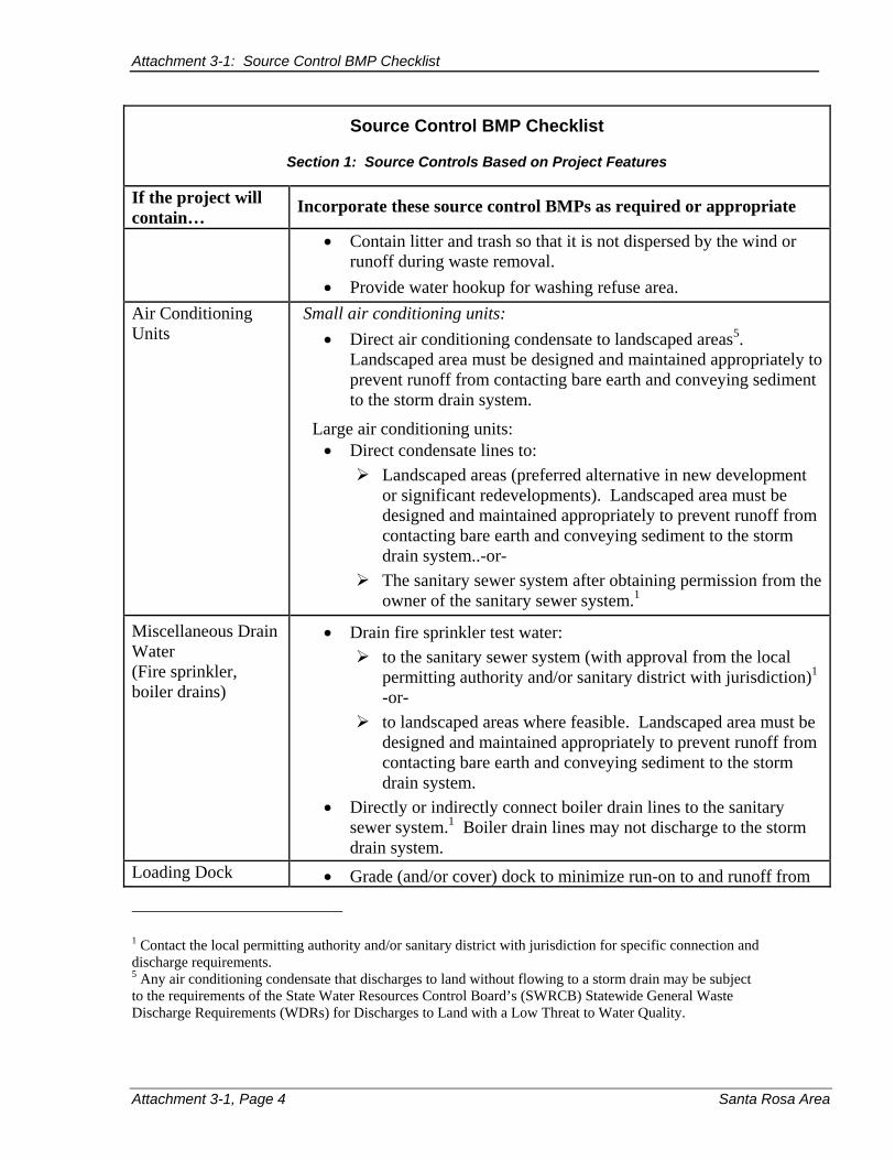
Attachment 3-1: Source Control BMP Checklist
Source Control BMP Checklist
Section 1: Source Controls Based on Project Features
If the project will contain… Incorporate these source control BMPs as required or appropriate
x Contain litter and trash so that it is not dispersed by the wind or runoff during waste removal.
x Provide water hookup for washing refuse area. Air Conditioning Units
Small air conditioning units: x Direct air conditioning condensate to landscaped areas5 .
Landscaped area must be designed and maintained appropriately to prevent runoff from contacting bare earth and conveying sediment to the storm drain system.
Large air conditioning units: x Direct condensate lines to: ¾ Landscaped areas (preferred alternative in new development
or significant redevelopments). Landscaped area must be designed and maintained appropriately to prevent runoff from contacting bare earth and conveying sediment to the storm drain system..-or-
¾ The sanitary sewer system after obtaining permission from the owner of the sanitary sewer system. 1
Miscellaneous Drain x Drain fire sprinkler test water: Water ¾ to the sanitary sewer system (with approval from the local (Fire sprinkler, permitting authority and/or sanitary district with jurisdiction)1
boiler drains) -or¾ to landscaped areas where feasible. Landscaped area must be
designed and maintained appropriately to prevent runoff from contacting bare earth and conveying sediment to the storm drain system.
x Directly or indirectly connect boiler drain lines to the sanitary sewer system.1 Boiler drain lines may not discharge to the storm drain system.
Loading Dock x Grade (and/or cover) dock to minimize run-on to and runoff from
1 Contact the local permitting authority and/or sanitary district with jurisdiction for specific connection and discharge requirements. 5 Any air conditioning condensate that discharges to land without flowing to a storm drain may be subject to the requirements of the State Water Resources Control Board’s (SWRCB) Statewide General Waste Discharge Requirements (WDRs) for Discharges to Land with a Low Threat to Water Quality.
Attachment 3-1, Page 4 Santa Rosa Area

Attachment 3-1: Source Control BMP Checklist
Source Control BMP Checklist
Section 1: Source Controls Based on Project Features
If the project will contain… Incorporate these source control BMPs as required or appropriate
the loading area. x Position roof downspouts to direct storm water away from the
loading area. x Storm water collected at loading docks should be discharged to the
sanitary sewer, not the storm drain. The area should be covered to minimize amount of storm water collected, and graded and/or bermed to prevent run-on.1
x Install door skirts between the trailers and the building to prevent exposure of loading activities to rain.
x Contain litter and trash. Parking Lot x Reduce parking lot size.
x Reduce impervious surface in parking lots, when appropriate. x Provide spill prevention and clean-up plan. x Provide trash cans. x Sweep regularly. x Avoid discharging wash water resulting from cleaning to the storm
drain. x Drain storm water to landscaped area prior to discharge.
Landscaped area must be designed and maintained appropriately to prevent runoff from contacting bare earth and conveying sediment to the storm drain system.
Parking Garage x Design with smaller footprint. x Design to prevent run on. x Connect interior level floor drains to a water treatment device
approved by the City or County prior to discharging to the sanitary sewer system. Treatment devices need regular maintenance to be effective.1
See also “Roofs.”
1 Contact the local permitting authority and/or sanitary district with jurisdiction for specific connection and discharge requirements.
SUSMP Guidelines Attachment 3-1, Page 5

Attachment 3-1: Source Control BMP Checklist
Source Control BMP Checklist
Section 1: Source Controls Based on Project Features
If the project will contain… Incorporate these source control BMPs as required or appropriate
Outdoor x Cover or design with BMPs to limit the potential for runoff to Equipment/Materials contact pollutants.Storage Area
x Roof storage areas containing non-hazardous liquids and contain by using berms, dikes, liners, vaults or similar spill containment devices. This requirement does not apply to the storage of hazardous materials. For requirements regarding the storage of hazardous materials, contact Hazardous Materials Division of the Sonoma County Department of Emergency Services (for projects in unincorporated Sonoma County) or the Santa Rosa Fire Department (for projects in the City of Santa Rosa).
x Provide spill prevention and clean-up plan. Vehicle Cleaning for x Discharging washwater to the storm drain system is prohibited. Multifamily Residential Developments
x Discourage vehicle/equipment washing by removing hose bibs and installing signs prohibiting such uses.
x Post a sign indicating the location and allowed uses in the designated wash area.
x Ensure areas are paved, designed to prevent run-on to or runoff from the area, are roofed, have an approved pretreatment device and are plumbed to drain to the sanitary sewer.5 The pretreatment device must be maintained regularly to be effective.
Attachment 3-1, Page 6 Santa Rosa Area

Attachment 3-1: Source Control BMP Checklist
Source Control BMP Checklist
Section 2: Source Controls Based on Project Activities
If the completed project will involve the following activities…
Incorporate these source control BMPs, as required or appropriate
Vehicle Cleaning for x Discharging washwater to the storm drain system is prohibited. Fleets or Commercial Vehicle/equipment washing areas:
Facilities x Ensure areas are paved, designed to prevent run-on to or runoff from the area, are roofed, have an approved pretreatment device and are plumbed to drain to the sanitary sewer.6 The pretreatment device must be maintained regularly to be effective.
x Post a sign indicating the location and allowed uses in the designated wash area.
Commercial/industrial facilities having vehicle/equipment cleaning needs: x Provide a roofed, bermed area for washing activities –or- x Discourage vehicle/equipment washing by removing hose bibs
(faucets) and installing signs prohibiting such uses.
Commercial Car Wash Facilities: x Design and operate such that no runoff from the facility is
discharged to the storm drain system. Discharge wastewater from the facility to the sanitary sewer.
6 Contact the local permitting authority and/or sanitary district with jurisdiction for specific connection and discharge requirements.
SUSMP Guidelines Attachment 3-1, Page 7

Attachment 3-1: Source Control BMP Checklist
Source Control BMP Checklist
Section 2: Source Controls Based on Project Activities
If the completed project will involve the following activities…
Incorporate these source control BMPs, as required or appropriate
Vehicle x Perform in a designated area indoors, or if such services must be Repair/Maintenance performed outdoors, in an area designed to prevent the run-on
and runoff of storm water. x Provide secondary containment for exterior work areas where
motor oil, brake fluid, gasoline, diesel fuel, radiator fluid, acid-containing batteries or other hazardous materials or hazardous wastes are used or stored. Do not install storm drains within the secondary containment areas.
x Do not install floor drains in vehicle service facilities [unless the floor drains are connected to wastewater pretreatment systems prior to discharge to the sanitary sewer, for which an industrial waste discharge permit has been obtained].6
x Do not connect tanks, containers or sinks used for parts cleaning or rinsing to the storm drain system. Wastes from parts cleaning should be collected and hauled off by an approved hazardous waste hauler. Tanks, containers or sinks used for such purposes may be, in some instances, connected to the sanitary sewer system if connected to an approved pretreatment system and allowed by an industrial waste discharge permit.6
Food Service x Ensure that facilities have a sink or other floor mat, container, and equipment cleaning area that is connected to the sanitary sewer system.6
x The cleaning area shall be large enough to clean the largest mat or piece of equipment to be cleaned. The cleaning area shall be indoors or in a roofed area outdoors; both areas must be plumbed to the sanitary sewer.6
x Design outdoor cleaning areas to prevent storm water run-on from entering the sanitary sewer and to prevent storm water runoff from carrying pollutants to the storm drain.
x Post signs indicating that all food service equipment washing activities shall be conducted in this area.
x Avoid discharge runoff from food service areas, trash enclosures, recycling areas, and/or food compactor enclosures or
Contact the local permitting authority and/or sanitary district with jurisdiction for specific connection and discharge requirements.
Attachment 3-1, Page 8 Santa Rosa Area
6

Attachment 3-1: Source Control BMP Checklist
Source Control BMP Checklist
Section 2: Source Controls Based on Project Activities
If the completed project will involve the following activities…
Incorporate these source control BMPs, as required or appropriate
Food Service (continued)
similar facilities to the storm drain system. Design trash enclosure areas to avoid run-on to the trash enclosure area. Connect any drains installed in or beneath dumpsters, compactors, and tallow bin areas serving food service facilities to the sanitary sewer.6
Outdoor Process x Perform process activities either indoors or in roofed outdoor Activities areas. If performed outdoors, design the area to prevent run-on to
and runoff from the area with process activities. x Perform washing or steam cleaning at an appropriately equipped
facility that drains to the sanitary sewer.6
x Drain process equipment areas to the sanitary sewer system. 6
Fuel Dispensing x Ensure that fueling areas have impermeable surfaces (i.e., Areas Portland cement concrete or equivalent smooth impervious
surface) that are: a) graded at the minimum slope necessary to prevent ponding; and b) separated from the rest of the site by a grade break that prevents run-on of storm water to the maximum extent practicable.
x The fueling area must be roofed and the roof’s minimum dimensions must be equal to or greater than the area within the grade break or fuel dispensing area.
x The canopy (or roof) shall use downspouts that do not drain onto the fueling area.
Contact the local permitting authority and/or sanitary district with jurisdiction for specific connection and discharge requirements.
SUSMP Guidelines Attachment 3-1, Page 9
6

[This page intentionally left blank]

Attachment 3-2
Pervious Paving Fact Sheet

[This page intentionally left blank]

Attachment 3-2: Pervious Paving Fact Sheet
Pervious Pavement
4
Description
Pervious paving is used for light vehicle loading in parking areas. The term describes a system comprising a load-bearing, durable surface together with an underlying layered structure that temporarily stores water prior to infiltration or drainage to a controlled outlet. The surface can be porous such that water infiltrates across the entire surface of the material (e.g., crushed aggregate, porous concrete and porous asphalt), or it can be constructed of impermeable blocks separated by spaces and joints, through which the water can drain. This latter system is termed ‘permeable’ paving.
Advantages
Significant flow attenuation and improvement in water quality can be achieved by pervious pavements. The surface and subsurface infrastructure can remove both the soluble and fine particulate pollutants that occur in storm water runoff. Roof runoff can be piped into the subsurface storage area directly, which would increase the level of flow attenuation. Also, within lined systems, there is the opportunity for stored runoff to be piped out for reuse. Pervious pavements have a high level of acceptability because they are unobtrusive.
SUSMP Guidelines Attachment 3-2, Page 1

Attachment 3-2: Pervious Pavement
Limitations
x Permeable pavement can become clogged if improperly installed or maintained. However, this problem is minimized by the ease with which small areas of paving can be cleaned or replaced when blocked or damaged.
x Weeds will grow within the pervious paving unless rigorously maintained. x Use should be limited to car parking areas and other lightly trafficked or
nontrafficked areas. Pervious surfaces are currently not considered suitable for roadways within the public right-of-way.
x When using un-lined, infiltration systems, there is some risk of contaminating groundwater, depending on soil conditions and aquifer susceptibility. However, this risk is likely to be small because the areas drained tend to have inherently low pollutant loadings.
x Use is restricted to gentle slopes. x High compaction of the subgrade to levels required for a firm base restricts
infiltration.
Design and Sizing Guidelines
The design of each layer of the pavement must be determined by the likely traffic loadings and their required operational life. To provide satisfactory performance, the following criteria should be considered:
x The subgrade should be able to sustain traffic loading without excessive deformation.
x The granular capping and sub-base layers should give sufficient load-bearing to provide an adequate construction platform and base for the overlying pavement layers.
x The pavement materials should not crack or suffer excessive rutting under the influence of traffic. This is controlled by the horizontal tensile stress at the base of these layers.
x Pervious pavements require a single size grading to give open voids. The choice of materials is therefore a compromise between stiffness, permeability and storage capacity.
x Because the sub-base and capping will be in contact with water for a large part of the time, the strength and durability of the aggregate particles when saturated and subjected to wetting and drying should be assessed.
x A uniformly graded single size material cannot be compacted and is liable to move when construction traffic passes over it. This effect can be reduced by the use of angular crushed rock material with a high surface friction.
Runoff Coefficients for pervious pavements are presented on the Runoff Coefficient Chart for SUSMP Water Quality Design Storms, Attachment 4-3. Because of sub-base compaction, runoff rates are typically higher for pervious pavements than for landscaping. Pervious pavements by themselves do not treat runoff. However, because of
Attachment 3-2, Page 2 Santa Rosa Area

Attachment 3-2: Pervious Paving Fact Sheet
the higher infiltration rates compared to an impervious surface, the size of downstream treatment controls can be reduced.
Maintenance
A maintenance mechanism (see Chapter 5) shall be provided with the Storm Water Mitigation Plan. The maintenance mechanism shall state the parties’ responsibility for maintenance and upkeep.
Maintenance shall include the following:
Ongoing: x Keep landscaped areas well maintained x Prevent soil from washing onto the pavement
Pervious Pavement shall be inspected and maintained 2-3 times per year to review:
a) Vacuum clean surface using commercially available sweeping machines at the following times: x End of winter (April) x Mid-summer (July / August) x After autumn leaf-fall (November) x Inspect outlets yearly
b) As needed maintenance: x If routine cleaning does not restore infiltration rates, then reconstruction of part of
the pervious surface may be required. x The surface area affected by hydraulic failure should be lifted for inspection of
the internal materials to identify the location and extent of the blockage. x Surface materials should be lifted and replaced after brush cleaning. Geotextiles
may need complete replacement. x Sub-surface layers may need cleaning and replacing. x Removed silts may need to be disposed of as controlled waste.
SUSMP Guidelines Attachment 3-2, Page 3

[This page intentionally left blank]

Chapter 4: Treatment Controls
4 Treatment Controls
This chapter explains the requirement to include storm water treatment controls in new development and redevelopment projects. This chapter also provides guidance on selecting and designing appropriate treatment controls.
4.1 Definitions and Purpose
Storm water treatment controls are engineered systems that are designed to remove pollutants from storm water. Treatment controls shall be used in conjunction with source control measures.
4.1.1 Regulatory Requirements
The municipal storm water NPDES permit requires that treatment controls be used for certain projects. The types of development projects that must have treatment controls include the following:
a) Development projects that create one acre (43,560 square feet) or more of new impervious surface. This category includes development of any type on public or private land, which falls under the planning and building authority of Sonoma County or City of Santa Rosa, where one acre or more of new impervious surface1, collectively over the entire project site, will be created. Project phasing to decrease impervious surface area shall not exempt the project from SUSMP requirements.
1 The municipal storm water NPDES permit defines impervious surface as “all areas where improvements result in a ground surface that significantly limits natural percolation rates including, but not limited to, asphalt, cement, pavers, buildings, and plastic liners that are associated with the project.”
SUSMP Guidelines 4-1

Chapter 4: Treatment Controls
Storm water treatment wet pond in Fremont, California
b) Streets, roads, highways and freeways that create one acre (43,560 square feet) or more of new impervious surface. This category includes any newly constructed impervious surface used for the transportation of pedestrians, bicycles, and motorized vehicles.
c) Redevelopment projects that are located on an already developed site and result in the addition of and/or reconstruction of one acre (43,560 square feet) or more of new impervious surface. Only the additional and/or reconstructed portion(s) of the site must be included in treatment design. Excluded from this category are interior remodels and routine maintenance or repair, including roof or exterior surface replacement and resurfacing.
d) Development and redevelopment projects located directly adjacent to a natural waterway, modified natural waterway, or constructed channel or that require a new storm drain outfall to such waterway2, regardless of project size or impervious surface. This requirement is intended to protect environmentally sensitive areas. For redevelopment projects, excluded from this category are interior remodels and routine maintenance or repair, including roof or exterior surface replacement and resurfacing.
The types of projects that are required to include treatment controls may change in the future to encompass more projects.
4.1.2 Benefits of Using Treatment Controls
Storm water treatment controls are implemented to remove from storm water pollutants that are a concern to local creeks. Information on the effectiveness of different types of treatment controls in removing these pollutants is summarized in Attachments 4-1 and 4-2 and information about what are the particular pollutants of concern is described below in Subsection 4.1.3.
Aside from meeting the municipal storm water NPDES permit requirement, the use of landscape-based storm water treatment controls can provide an aesthetically pleasing landscape that is viewed as a project amenity. Many well designed landscape
2 The terms, “natural waterway,” “modified natural waterway,” and “constructed channel” are defined in the Sonoma County Water Agency’s Flood Control Design Criteria and are included in the definitions section of these guidelines.
4-2 Santa Rosa Area
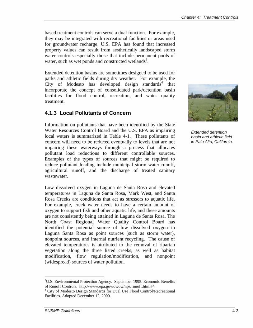
Chapter 4: Treatment Controls
based treatment controls can serve a dual function. For example, they may be integrated with recreational facilities or areas used for groundwater recharge. U.S. EPA has found that increased property values can result from aesthetically landscaped storm water controls especially those that include permanent pools of water, such as wet ponds and constructed wetlands3.
Extended detention basins are sometimes designed to be used for parks and athletic fields during dry weather. For example, the City of Modesto has developed design standards4 that incorporate the concept of consolidated park/detention basin facilities for flood control, recreation, and water quality treatment.
4.1.3 Local Pollutants of Concern
Information on pollutants that have been identified by the State Water Resources Control Board and the U.S. EPA as impairing local waters is summarized in Table 4-1. These pollutants of concern will need to be reduced eventually to levels that are not impairing these waterways through a process that allocates pollutant load reductions to different controllable sources. Examples of the types of sources that might be required to reduce pollutant loading include municipal storm water runoff, agricultural runoff, and the discharge of treated sanitary wastewater.
Low dissolved oxygen in Laguna de Santa Rosa and elevated temperatures in Laguna de Santa Rosa, Mark West, and Santa Rosa Creeks are conditions that act as stressors to aquatic life. For example, creek water needs to have a certain amount of oxygen to support fish and other aquatic life, and these amounts are not consistently being attained in Laguna de Santa Rosa. The North Coast Regional Water Quality Control Board has identified the potential source of low dissolved oxygen in Laguna Santa Rosa as point sources (such as storm water), nonpoint sources, and internal nutrient recycling. The cause of elevated temperatures is attributed to the removal of riparian vegetation along the three listed creeks, as well as habitat modification, flow regulation/modification, and nonpoint (widespread) sources of water pollution.
3U.S. Environmental Protection Agency. September 1995. Economic Benefits of Runoff Controls. http://www.epa.gov/owow/nps/runoff.html#4 4 City of Modesto Design Standards for Dual Use Flood Control/Recreational Facilities. Adopted December 12, 2000.
Extended detention basin and athletic field in Palo Alto, California.
SUSMP Guidelines 4-3

Chapter 4: Treatment Controls
Table 4-1 Pollutants or Stressors Listed as Impairing Local Creeks
Pollutants or Stressors
Mar
kW
est
Cre
ek
Sant
aR
osa
Cre
ek
Lagu
nade
San
taR
osa
Peta
lum
aR
iver
5
Sono
ma
Cre
ek 5
Low dissolved oxygen 9
Nitrogen 9 9 9
Phosphorus 9 9 9
Sedimentation/siltation 9 9 9 9
Temperature 9 9 9
Diazinon 9
Pathogens 9 9 9
All of the pollutants listed in Table 4-1 have a number of ways that they reach local creeks. Municipal storm water runoff may contain nitrogen and phosphorus compounds from fertilizers that are used excessively to maintain landscaping. The pesticide, diazinon, has exceeded safe levels for aquatic life in the Petaluma River and its nationwide use in urban areas for yard care and ant control is being phased out. Microbial pathogens include bacteria and viruses that cause disease. These pathogens are often found in storm water runoff from failing septic tanks, sewer overflows, and animal wastes.
Besides the pollutants listed above, storm water can mobilize and transport other pollutants from everyday activities. Some examples include tire and brake pad wear, engine combustion products, petroleum product leaks from vehicles, yard wastes, litter, pesticides, fireplace soot, and atmospheric transport of eroded soil by wind and rain.
In terms of removing pollutant from storm water, it is fortunate that most pollutants tend to become attached through adsorption onto particles, such as suspended and settleable solids. Particulate-associated pollutants are easier to remove from storm water than soluble pollutants that remain dissolved.
5 The Petaluma River and Sonoma Creek are listed as impaired by “nutrients,” which typically means nitrogen and phosphorus compounds.
Santa Rosa Area 4-4

Chapter 4: Treatment Controls
Total suspended solids is a measurement of the amount of sediment entrained in storm water runoff. Total suspended solids are also an indirect measure of other pollutants carried in storm water runoff because nitrogen and phosphorous compounds, pesticides, and pathogens are typically attached to sediment particles.
4.2 Selecting Treatment Controls
4.2.1 Types of Treatment Controls
The types of treatment controls can be categorized into two groups, landscape-based and non-landscaped based. Generally landscape-based treatment controls are non-proprietary while non-landscape- based treatment controls are proprietary. Some examples of landscape-based, non-proprietary controls include vegetated swales, bioretention areas, extended detention basins, and wet ponds. These contrast with the manufactured, proprietary treatment controls that tend to be installed below ground and operate using proprietary filtering media or vortex separation that removes litter and other larger-sized solids from storm water. Table 4-2 provides an overview of most of the common treatment controls in use in the San Francisco Bay Area.
Underground vaults, manufactured vortex separators, water quality inlets, and manufactured drain inserts have limited applicability. Underground vaults typically lack the detention time required for removal of pollutants associated with fine particles6. They also require frequent maintenance. Because vaults may be “out of sight, out of mind,” experience shows that the required maintenance may not occur. If vaults are allowed, they must be sealed against mosquito access and must also include suitable access doors and hatches to allow for frequent inspections and maintenance. The San Francisco Bay Regional Water Quality Control Board’s Executive Officer7 concluded the following regarding the use of manufactured drain inserts (which he calls “inlet filters”): “it would be very unlikely for a proposal using inlet filters as the sole treatment measures to meet the MEP [maximum extent practicable] standard.”
6 Contra Costa County Stormwater Quality Requirements for Development Applications. Stormwater C.3 Guidebook. 3rd Draft January 2005. 7 Letter from Bruce H. Wolfe, Executive Officer of the San Francisco Bay Regional Water Quality Control Board to the Bay Area Stormwater Management Agencies Association (BASMAA), dated August 5, 2004.
SUSMP Guidelines 4-5

Chapter 4: Treatment Controls
Table 4-2 Post-Construction Storm Water Treatment Control
Categories and Descriptions Storm Water Treatment Control8
Description
Landscape-Based Treatment Controls
Vegetated swale Shallow, vegetated channels with flat bottoms and shallow side slopes that are designed to collect, treat through sedimentation and some infiltration, and slowly convey storm water runoff to downstream discharge points.
Bioretention area System designed to remove pollutants through sedimentation and filtration using a combination of vegetated buffer strip, sand bed, ponding area, organic layer, planting soil, and plants.
Extended detention basin
Constructed basins with drainage outlets that are designed to detain runoff from a water quality design storm for some minimum drawdown time (e.g., use 85th percentile of 24-hour storm event for calculating the storm water volume and 40 hours as the drawdown time for sizing the outlet orifices) to allow settling of sediment and associated pollutants. Should be dry between storms and not have a permanent pool of water.
Vegetated buffer strip
Linear strips of vegetated surfaces that are designed to treat sheet runoff flow from adjacent impervious surfaces.
Constructed Constructed detention basins that have a wetland permanent pool of water throughout the year (or
at least during the wet season) and a capacity for temporary additional storage of runoff that is released via an outlet structure. They differ from wet ponds in that they are typically shallower and have greater vegetation cover.
Wet pond Constructed detention basins that have a permanent pool of water throughout the year (or at least during the wet season) and a capacity for temporary additional storage of runoff that is released via an outlet structure. Wet ponds typically differ from constructed wetlands by being deeper and having less vegetation.
Media filter The Austin sand filtration system is a type of non-proprietary filter that is installed at grade. It consists of a pretreatment sedimentation basin, filter bed filled with sand, and under drain piping system. Also, note that there are other, subsurface media types of filters listed in the Non Landscape-Based Treatment Controls section of this table.
8 This is not an inclusive list.
Santa Rosa Area 4-6

Chapter 4: Treatment Controls
Table 4-2 Post-Construction Storm Water Treatment Control
Categories and Descriptions Storm Water Treatment Control8
Description
Infiltration basin Shallow impoundment that is designed to infiltrate storm water into the subsurface soils.
Non-Landscape Based, Subsurface Treatment Controls Media filter and Two-chambered systems that include a Manufactured pretreatment sedimentation basin and a filter bed media filter filled with sand and/or other types of materials
(such as compost). There are both non-proprietary (Washington, D.C., and Delaware sand filters) and proprietary types that use cartridge filters located in underground vaults and pipes.
Manufactured Proprietary, cylindrical chambers that allow vortex separator9 settling and flotation of pollutants, such as litter
and other large-sized particles, and treated water exits the chamber in a swirling fashion.
Manufactured drain insert9, 10
Drain inserts are manufactured filters or fabric placed in a storm drain inlet to remove sediment and debris.
4.2.2 Evaluation of the Applicability of Treatment Controls
Attachments 4-1 and 4-2 contain an evaluation of the applicability of different types of storm water treatment controls for use in Sonoma County. This evaluation focused on eleven types of treatment controls that have been used most frequently in the San Francisco Bay Area. Vegetated swale in Redwood City, California.
The evaluation criteria included the following: effect on pollutants that are impairing local creeks; project size; application to different types of land uses; limitations on use (including steep slopes, groundwater level, and potential for mosquito breeding); maintenance requirements; costs;
9 The North Coast Regional Water Board staff stated in a letter dated May 23, 2005 that these two treatment controls do not adequately treat the pollutants of concern. If these treatment controls are used, they must be combined with treatment controls that adequately treat the pollutants of concern. 10 Not recommended by Regional Water Board staff unless part of a multistep treatment process. Also, see Handbook’s Attachment 4-1.
SUSMP Guidelines 4-7

Chapter 4: Treatment Controls
application to different types of soil; and Regional Water Quality Control Boards staff’s recommendations.
Based on this evaluation, the eleven treatment controls are categorized as to their applicability for use in Sonoma County. As shown in Table 4-3, four of the treatment controls have wide applicability in Sonoma County, four have some applicability, and three others have limited applicability.
.A treatment control with limited applicability may be considered for use as a component in a multi-step treatment process, which includes a series of different types of treatment controls that remove pollutants from storm water. The use of infiltration basins is limited in Sonoma County to sites with A and B well-drained soils; sites must also be evaluated to protect groundwater from contamination in storm water runoff. Infiltration treatment controls are not recommended in areas with industrial activity and areas with high groundwater. In such areas infiltration treatment controls may be allowed if storm water is treated prior to infiltration in order to protect groundwater. Manufactured vortex separators generally perform well in removing litter and large-sized particles but should be used in a multi-step treatment process in order to remove other pollutants from storm water. Manufactured drain inserts are not recommended unless part of a multi-step treatment process.
Specific information about why these different treatment controls were determined to fit in these categories is contained in Attachments 4-1 and 4-2.
Table 4-3 Applicability of Treatment Controls in Sonoma County Applicability Type of Treatment Control BMP
Wide Applicability
Vegetated swale Bioretention area Extended detention basin Vegetated buffer strips
Some Applicability
Constructed wetland Wet pond Media filter Manufactured media filter
Limited Applicability
Infiltration basin Manufactured vortex separator Manufactured drain inserts
Santa Rosa Area 4-8

Chapter 4: Treatment Controls
4.2.3 Selection of Treatment Controls
In general, landscape-based storm water treatment controls are encouraged as preferable to treatment controls that are placed underground. Landscape-based storm water treatment controls with wide applicability in Sonoma County are vegetated swales, vegetated buffer strips, extended detention basins, and bioretention areas.
The CASQA Handbook (2003) recommends that extended detention basins be used for projects that are larger than five acres in order to avoid having small diameter orifices in the outlet structure that are prone to clogging and because of economies of scale. Extended detention basins should be designed to go dry between storms.
Wet ponds are typically used on projects that have a size between ten and hundreds of acres. Wet ponds are designed to include a permanent pool of water that is equal to twice the size of the required water quality volume (see Section 4.3.2 for Volume-Based Hydraulic Sizing Requirements). Most of the other treatment controls are appropriate for smaller projects, or they could be used in larger projects if a sufficient number of the treatment units were installed over the site.
4.2.4 Mosquito Control
Increasing attention is being placed on the potential for treatment controls to breed mosquitoes. The municipal storm water NPDES permit finds (Finding 10) that the North Coast Regional Water Quality Control Board expects close collaboration among the Permittees, the Regional Water Quality Control Board, local vector control agencies, and the State Department of Health Services regarding “the implementation, operation, and maintenance of storm water treatment controls in order to minimize the risk to public health from water borne diseases.”
Ronald Keith, Assistant Manager/Vector Ecologist for the Marin/Sonoma Mosquito & Vector Control District, reported that most of the types of mosquitoes that prefer to breed in storm water treatment controls can transmit diseases, such as encephalitis and West Nile virus11. Treatment controls that rely
11 Based on Ronald Keith’s presentation to SUSMP Guidance Document TAC on September 17, 2004.
SUSMP Guidelines 4-9

Chapter 4: Treatment Controls
on a permanent pool of water to operate are especially susceptible to mosquito breeding.
The Marin/Sonoma Mosquito & Vector Control District encourages the following approach to control mosquito breeding9:
1. Use a design that minimizes opportunities for mosquito breeding (see General Design Principles below).
2. Have a maintenance plan and implement the plan to make sure that treatment controls are cleaned out.
3. Provide physical access, such as a gate, so that staff from the Marin/Sonoma Mosquito & Vector Control District can monitor and treat mosquitoes.
4. Provide the Marin/Sonoma Mosquito & Vector Control District with information about the locations of storm water treatment controls so that they can be added to their database of locations to monitor for mosquito breeding.
Some types of treatment controls are designed to include permanent pools of water; examples of these include wet ponds, constructed wetlands, manufactured vortex separators, some types of media filters (e.g., Delaware sand filter and Multi-Chambered Treatment Train), and some manufactured media filters.
The following design principles should be considered when selecting and designing storm water treatment controls:
General design principles x Consider using storm water treatment controls that do
not require a permanent pool of water. x Design treatment controls so that they will drain
completely within 72 hours. It is recommended that treatment controls be designed to drain within 72 hours since the fastest breeding mosquitoes in Sonoma County would require between four and ten days to mature.
x Use the hydraulic grade line of the site to select a treatment control that allows water to flow by gravity through the structure. Pumps are not recommended because they are subject to failure and often require sumps to hold water.
4-10 Santa Rosa Area

Chapter 4: Treatment Controls
x Use grouted rock energy dissipaters instead of loose rock.
Wet ponds and constructed wetlands x Design shoreline perimeters as steep and uniform as
practicable to discourage dense plant growth. x Use concrete or liners to minimize unwanted plant
growth where vegetation is unnecessary. x Maximize the amount of area that is greater than four
feet deep because deep, open areas of exposed water are typically unsuitable for mosquito rearing.
x Maximize circulation and aeration of water in ponds. x Design shoreline to be accessible to maintenance and
vector control crews for periodic inspections and maintenance.
x Use mosquito fish in ponded water.
4.3 Hydraulic Sizing Design Criteria for Water Quality
The municipal storm water NPDES permit contains storm water treatment control sizing criteria. Treatment controls can be divided generally into those that use flow-based and those that require volume-based designs (Table 4-4).
Table 4-4 Flow and Volume Based Treatment Control Designs
Type of Treatment Control BMPs Sizing Type Vegetated swale Flow Bioretention area Volume or Flow Extended detention basin Volume Vegetated buffer strips Flow Constructed wetland Volume Wet pond Volume Media filter Flow Manufactured media filter Flow Infiltration basin Volume Manufactured vortex separator Flow Manufactured drain inserts Flow
The flow-based treatment controls remove pollutants from a moving stream of storm water runoff, such as vegetated swales and media filters. Flow-based treatment controls operate primarily by filtration, settling, flotation, and infiltration.
SUSMP Guidelines 4-11

Chapter 4: Treatment Controls
The volume-based treatment controls detain and treat storm water primarily through settling and infiltration. Examples of these types of treatment controls are extended detention basins and wet ponds.
4.3.1 Flow-Based Hydraulic Sizing Requirements
The municipal storm water NPDES permit requires that flow-based treatment controls shall be designed to treat or infiltrate storm water. The recommended method for designing flow-based storm water treatment controls is:
“The flow rate of runoff produced by the 85th percentile mean annual 24-hour storm event hourly rainfall intensity, as determined from the local historical rainfall record.”
According to the SUSMP the rainfall intensity that occurs during the 85th percentile mean annual 24 hour storm event is 0.21 inches per hour. The design constant intensity of 0.21 inches per hour does not vary by type of flow-based treatment control or time of concentration.
The SUSMP shows that this method is met by applying the following equation:
Q = (0.21)(C)(A)(K)
Where: Q = design flow rate (cfs) C = watershed runoff coefficient (developed condition) A = project area (acres) that drains to the treatment control K = k Factor
Information on the C coefficient and k Factors is located in Attachment 4-3. According to the Sonoma County Water Agency’s Flood Control Design Criteria, the k Factor is 1 for areas that receive 30 inches of mean annual precipitation.
4.3.2 Volume-Based Hydraulic Sizing Requirements
The municipal storm water NPDES permit allows three alternative numeric sizing criteria as described below:
4-12 Santa Rosa Area

Chapter 4: Treatment Controls
a. The volume of runoff produced from the 85th percentile of 24-hour storm event, as determined from the local historical rainfall record (approximately 0.92 inches in the Santa Rosa area);
b. The volume of runoff produced by the 85th percentile 24hour rainfall event, determined using the maximized capture storm water volume for the area, from the formula recommended in Urban Runoff Quality Management, WEF Manual of Practice No. 23/ASCE Manual of Practice No. 87, pp. 170-178 (1998);
The SUSMP shows that this method is met by applying the following equation:
V = (0.08’)(C)(K)(A)
Where: V = maximized storage volume (acre-feet) C = watershed runoff coefficient (developed condition) A = project area (acres) that drains to the treatment control K = k Factor
c. The volume of annual runoff based on unit basin storage water quality volume, to achieve 80 percent or more volume treatment by the method recommended in California Storm Water Best Management Practices Handbook – Industrial/Commercial (1993).
4.4 Technical Guidance on Design Landscape-Based Treatment Controls
of
The City of Santa Rosa and Sonoma County encourage the use of landscape-based treatment controls. This section contains fact sheets on the design of six landscape-based storm water treatment controls and one fact sheet on a subsurface treatment control. Non-standard designs may be considered and approved by local agencies.
Subsurface treatment controls should not be used unless it is infeasible to use landscape-based treatment controls, or if there is a potential to contaminate groundwater sources. Guidance on the design and use of manufactured media filters, manufactured vortex separators, and other proprietary treatment controls should
SUSMP Guidelines 4-13

Chapter 4: Treatment Controls
be obtained from the manufacturers and approved by the local agency.
The fact sheets are organized into the following five sections: description; advantages; limitations; design and sizing guidelines; maintenance; and figures. The fact sheets are intended to integrate general information about the treatment controls based on the CASQA Stormwater Best Management Practice Handbook New Development and Redevelopment and specific information on design and based on experience in the Bay Area.
The treatment controls covered by these fact sheets include: x Vegetated swales, x Bioretention areas, x Extended detention basins, x Vegetated buffer strips, x Constructed wetlands, x Wet ponds, and x Media filters.
4-14 Santa Rosa Area
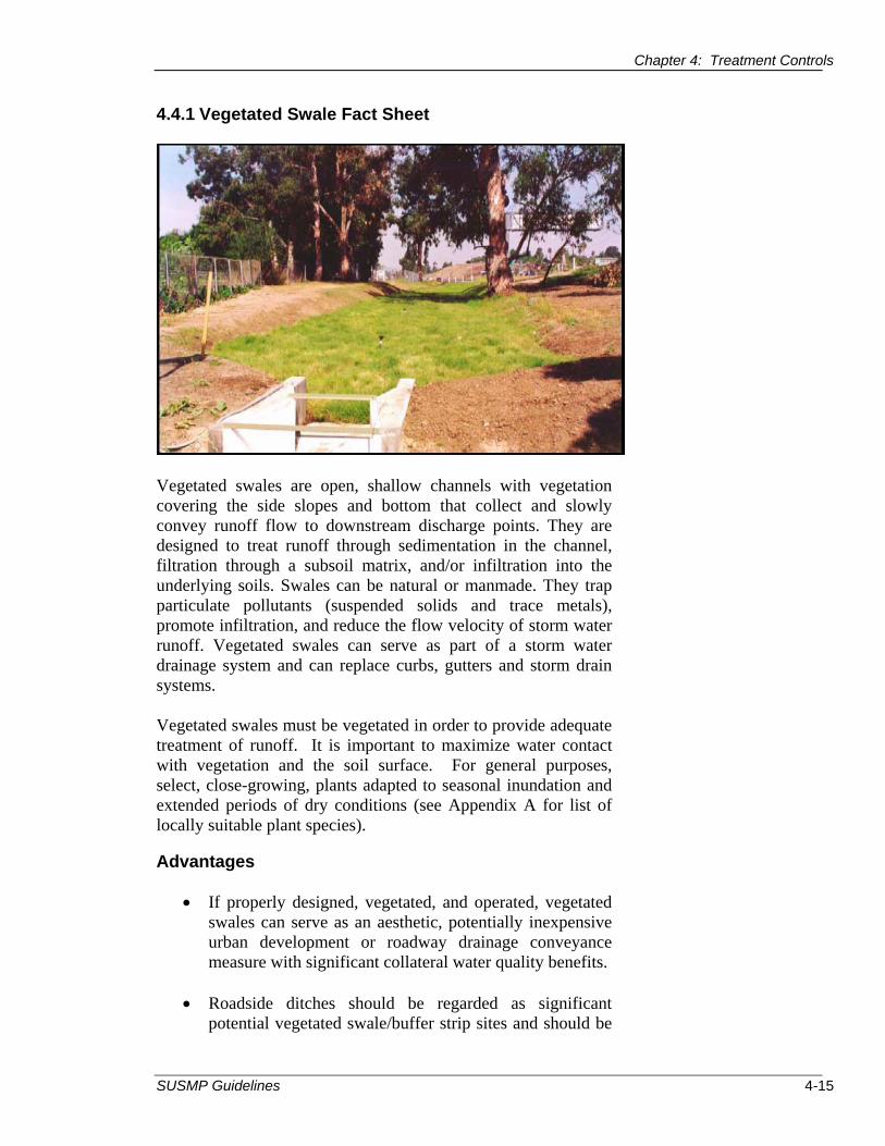
Chapter 4: Treatment Controls
4.4.1 Vegetated Swale Fact Sheet
Vegetated swales are open, shallow channels with vegetation covering the side slopes and bottom that collect and slowly convey runoff flow to downstream discharge points. They are designed to treat runoff through sedimentation in the channel, filtration through a subsoil matrix, and/or infiltration into the underlying soils. Swales can be natural or manmade. They trap particulate pollutants (suspended solids and trace metals), promote infiltration, and reduce the flow velocity of storm water runoff. Vegetated swales can serve as part of a storm water drainage system and can replace curbs, gutters and storm drain systems.
Vegetated swales must be vegetated in order to provide adequate treatment of runoff. It is important to maximize water contact with vegetation and the soil surface. For general purposes, select, close-growing, plants adapted to seasonal inundation and extended periods of dry conditions (see Appendix A for list of locally suitable plant species).
Advantages
x If properly designed, vegetated, and operated, vegetated swales can serve as an aesthetic, potentially inexpensive urban development or roadway drainage conveyance measure with significant collateral water quality benefits.
x Roadside ditches should be regarded as significant potential vegetated swale/buffer strip sites and should be
SUSMP Guidelines 4-15

Chapter 4: Treatment Controls
used for this purpose whenever possible as long as properly designed or modified.
Limitations
x� It can be difficult to avoid channelization in a vegetated swale.
x� Vegetated swales may be inappropriate for industrial sites or locations where chemical spills may occur
x� A single vegetated swale cannot treat a drainage area greater than 10 acres. Large areas may be divided and treated using multiple vegetated swales.
x� A thick vegetative cover is needed for these practices to function properly and prevent the resuspension of settled solids.
x� Vegetated swales are impractical in areas with steep topography.
x� Vegetated swales are ineffective and may even erode when flow velocities are high, if the vegetated cover is not properly maintained.
x� In some places, their use is restricted by law. Many local municipalities require curb and gutter systems in residential areas.
Design and Sizing Guidelines
x� Flow rate based design determined by meeting the flow-based hydraulic sizing requirements described in Section 4.3.1.
x� Vegetated swale shall be designed so that the water level does not exceed 2/3rds the height of the grass or 4 inches, which ever is less, at the design treatment rate.
x� Longitudinal slopes shall not exceed 4%; 1 to 2% is recommended12 .
x� Minimum longitudinal slope for Type I swales in well drained (Type A or B) soils is 0.5%. Minimum longitudinal slope for Type II swales (or Type I swales in less well drained soils) is 1%.
x� Trapezoidal channels are normally recommended but other configurations, such as parabolic, can also provide substantial water quality improvement and may be easier to mow than designs with sharp breaks in slope.
x� Swales constructed in cut are preferred, or in fill areas that are far enough from an adjacent slope to minimize the potential for gopher damage. Do not use side slopes constructed of fill, which are prone to structural damage by gophers and other burrowing animals.
12 U.S. EPA. 2002. National Menu of BMPs for Storm Water Phase II.
4-16 Santa Rosa Area

Chapter 4: Treatment Controls
x Vegetation whose growing season corresponds to the wet season is preferred. Drought tolerant vegetation shall be considered especially for vegetated swales that are not part of a regularly irrigated landscaped area. See Appendix A for list of locally suitable plant species.
x The width of the swale shall be determined using Manning’s Equation:
S0.5 . Q = 1.49 * A * R0.67 * n
Where: Q = Treatment flow rate in cubic feet per second, A = Cross-section area in square feet, R = Hydraulic radius in feet, = A / P: P = wetted perimeter in feet S = Channel slope in feet per foot, n = Manning’s Roughness coefficient of 0.25
A Manning’s Roughness coefficient of 0.20 may be used if the Maintenance Plan specifically requires regular mowing throughout the year when the vegetation height exceeds 4 inches.
x Vegetated swales shall have a maximum treatment width of 10 feet. The vegetated swale bed shall be at least 2-feet wide and no more than 7-feet wide. Parallel swales may be used if calculations show greater width is needed.
x Flow may enter the vegetated swale: o As overland flow from landscaping (no special
requirements), o As overland flow from pavement (cutoff wall
required), o Through a curb opening, pavement at least 2
inches above the protected apron, o Through a curb drain, or o Through a stepped manhole.
x The bed of the vegetated swale flow area shall slope at about 2% from toe of side slope to center of swale. Side slopes shall be not be greater than a 3 to 1 slope.
x If vegetation is not established by October 1st, a 1-year biodegradable loose weave geofabric shall be placed on swale surface.
x The longest flow path for the swale shall have a minimum retention time of 12 minutes for conditions when the treatment flows enter the vegetated swale uniformly along the swale length. The longest flow path
SUSMP Guidelines 4-17

Chapter 4: Treatment Controls
for the swale shall have a minimum retention time of 5 minutes if 90 percent or more of the treatment flow enters the swale at the upstream end.
x For vegetated swale Type 2 (underdrain) the perforated pipe trench shall be backfilled with ¾” crushed rock with a 2-inch bed underneath and 6-inch cover. (CalTrans Standard Section 68-1.025 permeable material Class 2) This rock layer shall be separated from the swale using a geofabric covered by a filter layer of sand or fine rock.
x Use schedule 40 PVC 6-inch diameter perforated pipe for projects located in the public right-of-way.
Maintenance
A maintenance mechanism (Chapter 5) shall be provided with the Storm Water Mitigation Plan. The maintenance mechanism shall state the parties’ responsibility for maintenance and upkeep.
Maintenance shall include the following:
x Mow and irrigate during dry weather to the extent necessary to keep vegetation alive. Where 6-inch high grasses are used, the grass height shall be at least 3 inches after mowing. Where mowed grasses are shown, the grass height shall be mowed when the height exceeds 3 inches.
x Remove obstructions and trash from vegetated swale. x Pesticides and fertilizers shall not be used in the swale.
Vegetated swales shall be inspected and maintained monthly to review:
x Obstructions and trash. x Ponded flow is drained within 72 hours after a rainfall
event. x Condition of vegetation including the adequacy of the
vegetative cover. x If ponding is observed, grading will be required to restore
positive drainage.
4-18 Santa Rosa Area

4%
SUSMP Guidelines 4-19

1.0 %
4-20 Santa Rosa Area

Chapter 4: Treatment Controls
4.4.2 Bioretention Area Fact Sheet
Description
The bioretention area best management practice (BMP) functions as a soil and plant-based filtration device that removes pollutants through a variety of physical, biological, and chemical treatment processes. These facilities normally consist of a vegetated buffer strip, sand bed, ponding area, organic layer or mulch layer, planting soil, and plants. The runoff’s velocity is reduced by passing over or through the vegetated buffer strip and subsequently distributed evenly along a ponding area. Exfiltration of the stored water in the bioretention area planting soil into the underlying soils occurs over two days.
Advantages
x Bioretention areas provide storm water treatment that enhances the quality of downstream water bodies by temporarily storing runoff in the BMP and releasing it over a period of two days to the receiving water.
x The vegetation provides shade and wind breaks, absorbs noise, and improves an area's landscape.
Limitations
x The bioretention area BMP is not recommended for areas with slopes greater than 20% or where mature tree removal would be required since clogging may result, particularly if the BMP receives runoff with high sediment loads.
SUSMP Guidelines 4-21

Chapter 4: Treatment Controls
x Bioretention areas are unsuitable for locations where the water table is within six feet of the ground surface and where the surrounding soil stratum is unstable.
x If runoff is stored for more than three days, bioretention areas have the potential to create very attractive habitats for mosquitoes and other vectors because of highly organic, often heavily vegetated areas mixed with shallow water.
Design and Sizing Guidelines
x Soil within bioretention areas shall be planting soil equivalent to a sandy loam, with a minimum percolation rate of 5 inches/hour and a maximum percolation rate of 10 inches per hour. In-situ testing shall be conducted after installation to verify that the material meets the percolation requirements. Planting soil will be to a minimum depth of at least 6 inches over a sand layer that is a minimum of 30 inches in depth.
x The bioretention area shall be sized to either: o Percolate the design treatment flow rate using an
infiltration rate of 5 inches per hour. No additional allowance is provided for storage or for infiltration rates in excess of 5 inches per hour; or,
o Store a 24-hour treatment volume, with a reduction of 1 inch per hour infiltration throughout the 24hour time period.
x Bioretention areas shall have a vegetation layer with either a 3-inch layer of mulch or grasses provided in areas between plantings. Shrubs and small trees shall be placed to anchor the bioretention area cover. Irrigation shall be provided to maintain vegetation in the bioretention area.
x The inlet to the overflow catch basin shall be at least 6inches above the low point of the bioretention area. The bioretention area shall have a minimum surface slope of 1 percent to local low points. Only areas at least 2 inches below the overflow catch basin elevation shall be considered in the surface area of the bioretention area.
x An underdrain system and liner shall be provided for the bioretention area except when percolation tests show that the native percolation rate is greater than 5 inches per hour and the depth to groundwater is greater than 10 feet from the surface of the bioretention area.
x One tree shall be provided per 50 square feet of planting area.
SUSMP Guidelines 4-22

Chapter 4: Treatment Controls
Maintenance
A maintenance mechanism (Chapter 5) shall be provided with the Storm Water Mitigation Plan. The maintenance mechanism shall state the parties’ responsibility for maintenance and upkeep.
Maintenance shall include the following:
x Inspect twice annually for obstructions and trash. If obstructions or trash are observed, these shall be removed.
x Inspect twice annually for ponded water. If ponded water is observed, the surface soils shall be removed and replaced with sand.
x Pesticides and fertilizers shall not be used in the bioretention area.
4-23 Santa Rosa Area
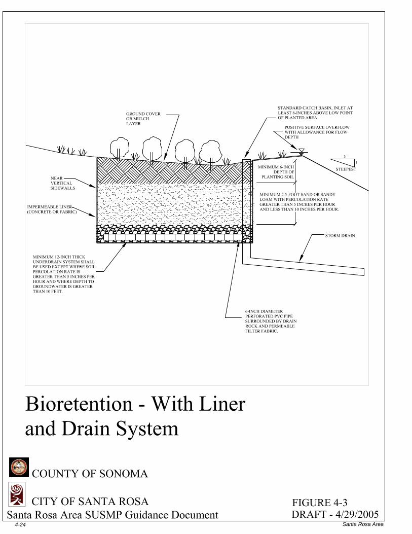
4-24 Santa Rosa Area

Chapter 4: Treatment Controls
4.4.3 Extended Detention Basin Fact Sheet
Description
Extended detention basins (a.k.a. dry ponds, dry extended detention basins, detention ponds, extended detention ponds) are basins whose outlets have been designed to detain the storm water runoff from a water quality design storm to allow particles and associated pollutants to settle. Unlike wet ponds, these facilities do not have a permanent pool of water. They can also be used to provide flood control by including additional flood detention storage.
Extended detention basin design must promote personal safety by being located along public streets to assure visual access to basin area. Site, street, and basin design shall be coordinated to orient buildings and streets for good surveillance of basin area.
Advantages
x Due to the simplicity of design, extended detention basins are relatively easy and inexpensive to construct and operate.
x Extended detention basins can provide substantial capture of sediment and the pollutants associated with particulates.
x Widespread application with sufficient capture volume can provide significant control of channel erosion and enlargement caused by changes to flow frequency
SUSMP Guidelines 4-25

Chapter 4: Treatment Controls
relationships resulting from the increase of impervious cover in a watershed.
Limitations
x Limitation of the diameter of the orifice may not allow use of extended detention in watersheds of less than 5 acres (would require an orifice of less than 0.5 inches diameter, which would be prone to clogging).
x Extended detention basins have only moderate pollutant removal when compared to some other structural storm water practices, and they are relatively ineffective at removing soluble pollutants.
x Dry basins can detract from the value of a home due to the adverse aesthetics of dry, bare areas and inlet and outlet structures.
Design and Sizing Guidelines
x Size extended detention basins to capture the required water quality volume. (See Section 4.3.2 for Volume-Based Hydraulic Sizing Requirements). At least 10 percent additional storage shall be provided to account for storage lost to deposited sediment.
x The outlet shall be sized with a drawdown time of 48 hours for the design water quality volume. The outlet shall have two orifices at the same elevation sized using the following equation:
a = (0.88x10⁻⁶) * A * (H-Ho).5 / C
Where: a = area of each orifice in square feet A = surface area of extended detention basin at mid-treatment storage elevation (square feet) H = elevation of basin when full (feet) Ho = final elevation of basin when empty (bottom of lowest orifice) (feet) C = orifice coefficient (0.6 typical for drilled orifice)
x The orifices shall each be a minimum diameter of 1 inch. Extended detention basins are not practical for small drainage areas because the minimum orifice diameter cannot be met. Each orifice shall be protected from clogging using a screen with a minimum surface area of 50
4-26 Santa Rosa Area

Chapter 4: Treatment Controls
times the surface area of the openings to a height of at least 6 times the diameter. The screen shall protect the orifice openings from runoff on all exposed sides.
x Extended detention basin shall have no greater than 3:1 side slopes.
x The optimal basin depth is between 2 and 5 feet. x If planting of the extended detention basin is not completed
by October 1st, a 1-year biodegradable loose weave geofabric shall be installed on exposed sideslopes to anchor soils.
x Piping into the extended detention basin shall have erosion protection. The inlet pipe shall have at least 1 foot of clearance to the pond bottom. As a minimum, a forebay with a 6-inch thick layer of Caltrans Section 72, Class 2 rock slope protection shall be placed at and below the inlet to the extent necessary for erosion protection. For each outlet, documentation shall be provided regarding adequacy of outlet protection, and a larger stone size may be necessary depending on the slope and the diameter of the outfall.
x Extended detention basin shall empty within 72 hours to avoid mosquito generation.
x Irrigation of the extended detention basin is optional. x A 12-foot wide maintenance ramp leading to the bottom of
the basin and a 12-foot wide perimeter access road shall be provided. If not paved, the ramp shall have a maximum slope of 5 percent. If paved, the ramp may slope 12 percent.
x The extended detention basin shall have a length to width ratio of at least 1.5:1.
x If the groundwater level is within 10 feet of the ground surface, a liner shall be provided to maintain storage capacity.
x A fixed vertical sediment depth marker shall be installed in the sediment forebay of the extended detention basin. The depth marker shall have a marking showing the depth where sediment removal is required. The marking shall be at a depth where the remaining storage equals the design water quality volume.
Maintenance
A maintenance mechanism (Chapter 5) shall be provided with the Storm Water Mitigation Plan. The maintenance mechanism shall state the parties’ responsibility for maintenance and upkeep.
SUSMP Guidelines 4-27

Chapter 4: Treatment Controls
Maintenance shall include the following:
x Vegetation shall be harvested annually during the summer. x The structural integrity of the outlet and berms shall be
inspected semiannually. x Accumulated trash and debris shall be removed from the
extended detention basin at the beginning and end of the wet season. (November and April).
x Remove sediment from the forebay when the sediment level reaches the level shown on the fixed vertical sediment marker.
x Pesticides and fertilizers shall not be used in the extended detention basin.
4-28 Santa Rosa Area

SUSMP Guidelines 4-29

Chapter 4: Treatment Controls
4.4.4 Vegetated Buffer Strip Fact Sheet
Description
Vegetated buffer strips (grassed buffer strips, filter strips, and grassed filters) are vegetated surfaces that are designed to treat sheet flow from adjacent surfaces. Vegetated buffer strips function by slowing runoff velocities and allowing sediment and other pollutants to settle and by providing some infiltration into underlying soils. Vegetated buffer strips were originally used as an agricultural treatment practice and have more recently evolved into an urban practice. With proper design and maintenance, vegetated buffer strips can provide relatively high pollutant removal. In addition, the public views them as landscaped amenities and not as storm water infrastructure. Consequently, there is little resistance to their use.
Advantages
x Require minimal maintenance activity (generally just erosion prevention and mowing).
x If properly designed, vegetated, and operated, vegetated buffer strips can provide reliable water quality benefits in conjunction with high aesthetic appeal.
x Flow characteristics and vegetation type and density can be closely controlled to maximize BMP effectiveness.
x Roadside shoulders act as an effective buffer strips when slope and length meet criteria described below.
SUSMP Guidelines 4-30

Chapter 4: Treatment Controls
Limitations
x May not be appropriate for industrial sites or locations where chemical spills may occur.
x Vegetated buffer strips cannot treat a very large drainage area.
x A thick vegetative cover is needed for these practices to function properly.
x Vegetated buffer strip length must be adequate and flow characteristics acceptable or water quality performance can be severely limited.
x Vegetative buffers may not provide treatment for dissolved pollutants except to the extent that flows across the vegetated surface are infiltrated into soils.
x This technology does not provide significant attenuation of the increased volume and flow rate of runoff during intense rain events.
Design and Sizing Guidelines
x Strip shall be sized as long as the site will reasonably allow. x Slopes should not exceed 15%. x Slope shall be at least 2% without a subdrain system and
0.5% with a subdrain system. x Minimum length (in direction of flow) shall be 15 feet. x Width shall be the same as the tributary area. x Either grass or a diverse selection of other low growing,
drought tolerant, native vegetation should be specified. Vegetation whose growing season corresponds to the wet season is preferred (see Appendix A for list of locally suitable plant species).
x Planting soil shall be to a minimum depth to at least 6 inches. Native soil may be used as a planting soil if approved by the landscape architect.
x Strip shall be free of gullies or rills.
Maintenance
A maintenance mechanism shall be provided with the Storm Water Mitigation Plan. The maintenance mechanism shall state the parties’ responsibility for maintenance and upkeep.
4-31 Santa Rosa Area

Chapter 4: Treatment Controls
Maintenance shall include the following:
x Mow and irrigate during dry weather to the extent necessary to keep vegetation alive. Where 6-inch high grasses are used, the grass height shall be at least 3 inches after mowing. Where mowed grasses are used, the grass height shall be mowed when the height exceeds 3 inches.
x Remove obstructions and trash from vegetated buffer strip. x Pesticides and fertilizers shall not be used in the vegetated
buffer strip.
Vegetated buffer strips shall be inspected and maintained twice a year to review:
x Obstructions and trash. x Ponded flow is drained within 72 hours after a rainfall
event. x Condition of vegetation. x If ponding is observed, grading will be required to restore
positive drainage.
SUSMP Guidelines 4-32

SUSMP Guidelines 4-33

Chapter 4: Treatment Controls
4.4.5 Constructed Wetlands Fact Sheet
Description
Constructed wetlands are constructed basins that have a permanent pool of water throughout the year (or at least throughout the wet season) and differ from wet ponds primarily in being shallower and having greater vegetation coverage. A distinction should be made between using a constructed wetland for storm water management and diverting storm water into a natural wetland. The latter practice is not recommended and in all circumstances, natural wetlands should be protected from the adverse effects of development, including impacts from increased storm water runoff. This is especially important because natural wetlands provide storm water and flood control benefits on a regional scale. Wetlands are among the most effective storm water practices in terms of pollutant removal and they also offer aesthetic value. As storm water runoff flows through the wetland, pollutant removal is achieved through settling and biological uptake within the wetland. Flow through the root systems forces the vegetation to remove nutrients and dissolved pollutants from the storm water.
Advantages
x If properly designed, constructed and maintained, constructed wetlands can provide substantial wildlife and wetlands habitat.
x Due to the presence of the permanent wet pool, properly designed and maintained constructed wetlands can provide
4-34 Santa Rosa Area
Chapter 4: Treatment Controls
significant water quality improvement across a relatively broad spectrum of pollutants including dissolved nutrients.
x Widespread application with sufficient capture volume can provide significant control of channel erosion and enlargement caused by changes to flow frequency relationships resulting from the increase of impervious cover in a watershed.
Limitations
x There may be some aesthetic concerns about a facility that looks swampy.
x Some concern about safety when constructed where there is public access.
x Mosquito and midge breeding is likely to occur in constructed wetlands.
x Cannot be placed on steep unstable slopes. x Need for base flow or supplemental water if water level is
to be maintained. x Require a relatively large footprint. x Depending on volume and depth, constructed wetland
designs may require approval from the State Division of Safety of Dams.
Design and Sizing Guidelines
x Size constructed wetlands to capture the required water quality volume (see Section 4.3.2 for Volume-Based Hydraulic Sizing Requirements).
x The permanent pool volume shall be twice the design for the required water quality volume. Wetland vegetation shall cover no more than 50 percent of the surface area.
x Marin/Sonoma Mosquito & Vector Control District staff shall be contacted and a vector abatement plan shall be prepared and implemented. To facilitate surveillance and control activities, 12-foot wide road access shall be provided along at least one side of the constructed wetlands where the pond is no less than 20 feet wide. Where the constructed wetland is greater than 20-feet wide, access shall be provided on both sides, or be designed such that all permanent ponding is within 20 feet of an access road.
x The permanent water depth shall not exceed four feet. There shall be relatively equal areas of shallow ponding (less than 6-inches deep), and moderately shallow ponding (greater than 18-inches deep) to encourage biodiversity.
SUSMP Guidelines 4-35
Chapter 4: Treatment Controls
x
x
x
x
The outlet shall be sized with a drawdown time of 48 hours for the required water quality volume. The recommended outlet shall have two low-level outlet orifices. The use of a single orifice is not recommended because of the risk of clogging, while use of more than two orifices is discouraged because the size of the holes is reduced, increasing susceptibility to clogging). The two orifices shall be at the same elevation and sized using the following equation13:
a = (1.44x10⁻⁶) * A * (H-Ho)0.5 / C
Where: a = total area of orifice in square feet A = surface area of constructed wetland at mid-treatment storage elevation (square feet) H = elevation of constructed wetland when full (feet) Ho = final elevation of constructed wetland when empty (bottom of lowest orifice) (feet) C = orifice coefficient (0.54 typical for orifice that is located at the floor of the constructed wetlands.)
The diameter of the orifices shall be calculated using the following equation:
d = [ (a * 4 * 144 ) / (n * pi ) ] 0.5
Where: d = orifice diameter (inches) n = number of orifices (2 is recommended)
The orifices shall each be a minimum diameter of 1 inch. Constructed wetlands are impractical for small drainage areas because the minimum orifice diameter cannot be met. Each orifice shall be protected from clogging using a screen with a minimum surface area of 50 times the area of the openings to a height of 6 times the diameter. The screen shall protect the orifice openings from runoff on all exposed sides. A separate valved discharge shall be provided for dewatering the constructed wetland. A water balance calculation shall be provided showing that the permanent pool water level will be maintained throughout the year. Pond liners and make-up water shall
13 California Department of Transportation. 2002. Storm Water Quality Handbooks, Project Planning and Design Guide.
4-36 Santa Rosa Area

Chapter 4: Treatment Controls
be included in the pond design to assure that the permanent pond water level is maintained.
x Constructed wetlands shall have no greater than 3:1 side slopes.
x Piping into the constructed wetlands shall have erosion protection. The inlet pipe shall have at least 1 foot of clearance to the constructed wetland bottom. As a minimum, a forebay with a 6-inch thick layer of Caltrans Section 72, Class 2 rock slope protection shall be placed at and below the inlet to the extent necessary for erosion protection. For each outlet, documentation shall be provided regarding adequacy of outlet protection, and a larger stone size may be necessary depending on the slope and the diameter of outfall.
x A sediment forebay shall be provided that is isolated from the wetland area by a loose riprap wall. The forebay shall contain 15% to 25% of the permanent pool volume and shall be at least three feet deep. Direct maintenance access shall be provided to the forebay. The bottom of the forebay shall be compacted, crushed rock. A fixed vertical sediment marker shall be installed in the sediment forebay. The marker shall be at a depth where 10 percent of the total permanent pool volume is lost due to sedimentation.
x Constructed wetlands shall have a length to width ratio of at least 1.5:1.
x Emergent plants shall be planted for energy dispersion and erosion control. A starter palate of beneficial bacteria shall be introduced to the constructed wetland. Vector control organisms (mosquito fish, etc.) shall be introduced to the constructed wetland after a sufficient period of time to control mosquitoes.
Maintenance
A maintenance mechanism (see Chapter 5) shall be provided with the Storm Water Mitigation Plan. The maintenance mechanism shall state the parties’ responsibility for maintenance and upkeep, including mosquito control.
Maintenance shall include the following:
x Vegetation shall be harvested annually during the summer. x The structural integrity of the outlet and berms shall be
inspected semiannually, including loss of integrity caused by burrowing animals.
SUSMP Guidelines 4-37

Chapter 4: Treatment Controls
x Accumulated trash and debris shall be removed from the constructed wetland at the middle and end of the wet season. (January and April).
x The constructed wetlands shall be stocked with mosquito fish annually and vegetation shall be maintained to assist their access to pond areas for mosquito control.
x Sediment shall be removed from the forebay when the sediment level reaches the level shown on the fixed vertical sediment marker.
x Pesticides and fertilizers shall not be used in the constructed wetlands.
4-38 Santa Rosa Area

SUSMP Guidelines 4-39

Chapter 4: Treatment Controls
4.4.6 Wet Ponds Fact Sheet
Description
Wet ponds (a.k.a. storm water ponds, retention ponds, wet extended detention ponds) are constructed basins that have a permanent pool of water throughout the year (or at least throughout the wet season) and differ from constructed wetlands primarily in having a greater average depth. Ponds treat incoming storm water runoff by settling and biological uptake. The primary removal mechanism is settling as storm water runoff resides in this pool, but pollutant uptake, particularly of nutrients, also occurs to some degree through biological activity in the pond. Wet ponds are among the most widely used storm water practices. While there are several different versions of the wet pond design, the most common modification is the extended detention wet pond, where storage is provided above the permanent pool in order to detain storm water runoff and promote settling.
Advantages
x If properly designed, constructed and maintained, wet ponds can provide substantial aesthetic/recreational value and wildlife and wetlands habitat.
x Ponds are often viewed as a public amenity when integrated into a park setting.
x Due to the presence of the permanent wet pool, properly designed and maintained wet ponds can provide significant
SUSMP Guidelines 4-40

Chapter 4: Treatment Controls
x water quality improvement across a relatively broad spectrum of constituents including dissolved nutrients.
x Widespread application with sufficient capture volume can provide significant control of channel erosion and enlargement caused by changes to flow frequency relationships resulting from the increase of impervious cover in a watershed.
Limitations
x Some concern about safety when constructed where there is public access.
x Mosquito and midge breeding is likely to occur in ponds. x Cannot be placed on steep unstable slopes. x Need for base flow or supplemental water if water level is
to be maintained. x Requires a relatively large footprint. x Depending on volume and depth, wet pond designs may
require approval from the State Division of Safety of Dams.
Design and Sizing Guidelines
x Wet ponds shall be sized to capture the required water quality volume (see Section 4.3.2 for Volume-Based Hydraulic Sizing Requirements).
x The outlet shall be sized with a drawdown time of 48 hours for the design water quality volume. The recommended outlet has two low-level outlet orifices. The use of a single orifice is not recommended because of the risk of clogging, and use of more than two orifices is discouraged because the size of the holes is reduced, increasing susceptibility to clogging). The two orifices shall be at the same elevation and sized using the following equation14:
a = (1.44x10⁻⁶) * A * (H-Ho)0.5 / C
Where: a = total area of orifice in square feet A = surface area of wet pond at mid-treatment storage elevation (square feet) H = elevation of wet pond when full (feet) Ho = final elevation of wet pond when empty (bottom of lowest orifice) (feet)
14 California Department of Transportation. 2002. Storm Water Quality Handbooks, Project Planning and Design Guide.
4-41 Santa Rosa Area

Chapter 4: Treatment Controls
C = orifice coefficient (0.54 typical for orifice that is located at the floor of the wet pond.)
The diameter of the orifices shall be calculated using the following equation:
d = [ (a * 4 * 144 ) / (n * pi ) ] 0.5
Where: d = orifice diameter (inches) n = number of orifices (2 is recommended)
x The orifices shall each be a minimum diameter of 1 inch. Wet ponds are not practical for small drainage areas because the minimum orifice diameter cannot be met. Each orifice shall be protected from clogging using a screen with a minimum surface area of 50 times the diameter of the openings to a height of 6 times the diameter. The screen shall protect the orifice openings from runoff on all exposed sides.
x A separate valved discharge shall be provided for dewatering the wet pond.
x The permanent pool volume shall be twice the design for the required water quality volume.
x The maximum permanent pool basin depth is 8 feet. Except at sideslopes, the permanent pool shall have a minimum depth of 4 feet. A depth greater than 4 feet limits the extent of vegetation to an aquatic bench around the perimeter of the pond that has a nominal depth of about 1 foot and variable width. This shallow bench protects the banks from erosion, enhances aesthetic values, and reduces drowning hazard.
x Wet ponds shall have no greater than 3:1 sideslopes and shall have a bench at a depth of 1 foot below the permanent pond elevation.
x Aeration and mixing devices shall be provided to maintain a minimum dissolved oxygen level of 6 mg/l within the pond at 5 pm. A minimum dissolved oxygen level of 1 mg/l shall be maintained at all times.
x Piping into the wet pond shall have erosion protection. The inlet pipe shall have at least 1 foot of clearance to the pond bottom. As a minimum, a forebay with a 6-inch thick layer of Caltrans Section 72, Class 2 rock slope protection shall be placed at and below the inlet to the extent necessary for erosion protection. For each outlet, documentation shall be provided regarding the adequacy of outlet protection, and a
SUSMP Guidelines 4-42

Chapter 4: Treatment Controls
larger stone size may be necessary depending on the slope and the diameter of outfall.
x A water balance calculation shall be provided showing that the permanent pool water level will be maintained throughout the year. Pond liners and make-up water shall be included in the pond design to assure that the permanent pond water level is maintained.
x A sediment forebay shall be provided that is isolated from the permanent pool by a loose riprap wall. The forebay shall contain 15% to 25% of the permanent pool volume and shall be at least three feet deep. Direct maintenance access shall be provided to the forebay. The bottom of the forebay shall be compacted, crushed rock. A fixed vertical sediment marker shall be installed in the sediment forebay. The marker shall be at a depth where 10 percent of the total sediment forebay volume is lost due to sedimentation.
x Wetland vegetation shall cover no more than 25% of the pond surface area.
x Emergent plants shall be planted for energy dispersion and erosion control. A starter palate of beneficial bacteria shall be introduced to the wet pond. Vector control organisms (mosquito fish, etc.) shall be introduced to the pond after a sufficient period to control mosquitoes.
x If planting of the wet pond sideslopes is not completed by October 1st, a 1-year biodegradable loose weave geofabric shall be placed on exposed sideslopes to anchor soils.
x A 12-foot wide maintenance ramp and perimeter access road shall be provided. The ramp shall have a maximum slope of 5 percent.
x The wet pond shall have a length to width ratio of at least 1.5:1.
x If the groundwater level is within 10 feet of the ground surface, a liner shall be provided.
x A fixed vertical sediment depth marker shall be installed in the permanent pool. The depth marker shall have a marking showing the depth where sediment removal is required. The marking shall be at a depth where 10 percent of the total permanent pool volume is lost to sediment
Maintenance
A maintenance mechanism (see Chapter 5) shall be provided with the Storm Water Mitigation Plan. The maintenance mechanism shall state the parties’ responsibility for maintenance and upkeep, including mosquito control.
4-43 Santa Rosa Area

Chapter 4: Treatment Controls
Maintenance shall include the following:
x Vegetation shall be harvested annually during the summer. x The structural integrity of the outlet and berms shall be
inspected semiannually. x Accumulated trash and debris shall be removed from the
wet pond at the middle and end of the wet season. (January and April).
x The wet pond shall be stocked with mosquito fish annually and vegetation shall be maintained to assist their access to ponded areas for mosquito control.
x Sediment shall be removed from the forebay when the sediment level reaches the level shown on the fixed vertical sediment marker.
x Pesticides and fertilizers shall not be used in the wet pond.
SUSMP Guidelines 4-44

SUSMP Guidelines 4-45

Chapter 4: Treatment Controls
4.4.7 Media Filter Fact Sheet
Description
Storm water media filters are usually two-chambered including a pretreatment settling basin and a filter bed filled with sand or other absorptive filtering media. As storm water flows into the first chamber, large particles settle out, and then finer particles and other pollutants are removed as storm water flows through the filtering media in the second chamber. There are a number of design variations including the surface Austin sand filter, which is pictured above, and the subsurface modified-Delaware sand filter. Media filters that are designed to drain water completely between storms are less susceptible to mosquito breeding.
Advantages
x Relatively high pollutant removal, especially for sediment and associated pollutants.
x Widespread application with sufficient capture volume can provide significant control of channel erosion and enlargement caused by changes to flow frequency relationships resulting from the increase of impervious cover in a watershed.
Limitations
x More expensive to construct than many other BMPs. x May require more maintenance that some other BMPs
depending upon the sizing of the filter bed.
4-46 Santa Rosa Area

Chapter 4: Treatment Controls
x Generally require more hydraulic head to operate properly (minimum 4 feet).
x If buried underground, require five feet clearance above the filter media to allow for maintenance.
x High solids loads will cause the filter to clog. x Works best for relatively small, impervious watersheds. x Surface filters in residential areas can present aesthetic and
safety problems if constructed with vertical concrete walls. x Certain designs maintain permanent sources of standing
water where mosquito and midge breeding is likely to occur.
Design and Sizing Guidelines
x Provide a factor of safety of 2 for clogging. x For underground system, minimum clearance from filter
media to ceiling of structure is five feet. x The maximum ponding depth over the filter shall not
exceed 2.67 feet. x Filter bed shall have at least 18-inch depth above
underdrain system. x Include energy dissipation in the inlet design to reduce
resuspension of accumulated sediment. x May need to pump treated flows because of head losses
through system. x For surface facilities, a maintenance ramp should be
included in the design to facilitate access to the sedimentation and filter basins for maintenance activities.
x Designs that utilize covered sedimentation and filtration basins should be accessible to vector control personnel via access doors to facilitate vector surveillance and control, if needed.
x Tributary area should be completely stabilized before media is installed to prevent premature clogging.
x Area of filter (Af) = 0.30 * Water Quality Volume * Df * Clog Factor
(h + Df)
Where: Area of Filter Media (Af) is in square feet, Water Quality Volume is in cubic feet Clogging Factor is 2 Df if the Depth of the Filter Media in feet
SUSMP Guidelines 4-47

Chapter 4: Treatment Controls
h is the average ponding depth (half of maximum depth) in feet
x The area of the settling basin shall equal the area of the filter media.
Maintenance
A maintenance mechanism (see Chapter 5) shall be provided with the Storm Water Mitigation Plan. The maintenance mechanism shall state the parties’ responsibility for maintenance and upkeep, including mosquito control.
Maintenance shall include the following:
x Cleaning or removal of top impervious settled layer. x Remove obstructions and trash from media filter.
Media filters shall be inspected and maintained monthly to review:
x Obstructions and trash. x Ponded flow within 72-hours of rainfall event. x Condition of media surface for impervious settling layer.
If ponded flow is observed, cleaning will be required to restore original filtering capabilities.
4-48 Santa Rosa Area

SUSMP Guidelines 4-49

Chapter 4: Treatment Controls
4.5 Limitations on Use of Infiltration Treatment Controls
The use of infiltration basins and infiltration trenches is limited in Sonoma County because of the scarcity of pervious soils and the need to protect groundwater from contamination from storm water runoff. The municipal storm water NPDES permit requires that restrictions be placed on treatment controls that function primarily as infiltration devices to prevent a violation of applicable groundwater quality objectives.
In addition, the SUSMP recommends against the use of infiltration BMPs in areas with industrial activity and areas subject to high groundwater. The SUSMP does state, however, that infiltration BMPs can be allowed where storm water is treated prior to infiltration “to ensure that groundwater is protected and the infiltration BMP in not rendered ineffective by overload.”
It is essential that site-specific factors be considered when evaluating the possible use of infiltration BMPs. This must include consultation with a geotechnical engineer to determine that infiltration BMPs will work based on the infiltration rates of local soils. An additional need is to determine whether the infiltration BMPs would be located in drainages without erosive soils or steep slopes that would risk clogging the infiltration BMP. Lastly, the possible use of infiltration BMPs needs to consider the site specific risk of contaminating groundwater given the site’s depth to groundwater, the quality of the storm water that will be infiltrated, the possibility of contamination from chemical spillage, and the risks of mobilizing and infiltrating contaminants that may already exist in the project site’s soils.
SUSMP Guidelines 4-50

Attachment 4-1
Evaluation of Storm Water Treatment Control BMPs

[This page intentionally left blank]

EVALUATION OF STORM WATER TREATMENT CONTROL BMPS
Introduction and Background
This attachment evaluates storm water treatment control BMPs for use at new development and redevelopment project sites. The purpose of this evaluation is to summarize readily available information about different types of treatment controls. The information in Attachments 4-1 and 4-2 should be used in conjunction with the information provided in Chapter 4 to select storm water treatment controls.
The nomenclature for the storm water treatment control BMPs (treatment controls) evaluated follows that used in the California Stormwater Quality Association (CASQA) Stormwater Best Management Practice Handbook New and Redevelopment (2003). For additional information on different types of treatment controls and how they operate, refer to this handbook or similar documents.
This evaluation of storm water treatment controls focuses on eleven types that have been used most frequently in the San Francisco Bay Area. These eleven types of treatment controls operate primarily by using a variety of physical/chemical treatment processes. These treatment processes include biofiltration, detention and settling, filtration, flow through separation, and infiltration, and absorption/adsorption.
The eleven treatment control types are categorized as to their applicability in Sonoma County. As shown in Table 4-1-1, four of the treatment controls evaluated are considered to have wide applicability for use in Sonoma County, four have some applicability, and three have limited applicability.
The following sections describe in more detail the basis for selecting the treatment controls for evaluation and the criteria that were used to evaluate the treatment controls. The Storm Water Treatment Control BMPs Evaluation Matrix (Attachment 4-2) summarizes the information obtained for each of the evaluation criteria.
Table 4-1-1 Treatment Controls Evaluated and Their Applicability
Applicability Type of Treatment Control BMP CASQA Handbook Reference
Vegetated swale TC-30 Wide Applicability Bioretention area TC-32
Extended detention basin TC-22 Vegetated buffer strips TC-31 Constructed wetland TC-21
Some Applicability Wet pond TC-20 Media filter TC-40 Manufactured media filter MP-40 Infiltration basin TC-11
Limited Applicability Manufactured vortex separator MP-51 Manufactured drain inserts MP-52
Attachment 4-1, Page 1

Basis of Selecting Treatment Controls for Evaluation
The treatment controls were selected generally to represent the types of BMPs that are either commonly being implemented in the San Francisco Bay Area and/or are recommended for use by staff from the North Coast and San Francisco Bay Regional Water Quality Control Boards. The eleven types of treatment controls represent about 95 percent of the treatment controls constructed in the San Francisco Bay Area between FYs 2001/02 and 2002/03.
Evaluation Criteria
The eleven treatment controls were evaluated based on the following factors or categories of factors: effect on pollutants of concern; project size; application to different types of land uses; limitations on use (including steep slopes, groundwater level, and potential for mosquitoes); maintenance requirements, costs; application to different types of soil; RWQCBs’ recommendations; and frequency of use.
Each of these evaluation criteria is described briefly below along with a synopsis of the evaluation results.
Effect on Pollutants of Concern
As described in Chapter 4 the Laguna de Santa Rosa and downstream areas have been identified by the U.S. EPA and/or the State Water Resources Control Board as impaired because of low dissolved oxygen, nitrogen and phosphorus compounds, sedimentation/siltation, and elevated temperature. In addition, Mark West and Santa Rosa Creeks are listed as impaired for sediment/siltation and elevated temperature, and Santa Rosa Creek is also impaired by pathogens. In the southern portion of Sonoma County the Petaluma River is listed as impaired by the pesticide diazinon, nickel, nutrients, and pathogens and Sonoma Creek is impaired by sedimentation/siltation, nutrients, and pathogens. One of the considerations in selecting treatment controls is their ability to remove these pollutants of concern.
The evaluation matrix includes information on the treatment controls’ ability to remove sediment (as measured by total suspended solids or TSS), nutrients (which include nitrogen and phosphorus compounds), and bacteria. The effect of treatment controls on the problem of low dissolved oxygen is addressed by including nutrients in the matrix. One possible cause of low dissolved oxygen in Laguna de Santa Rosa is a seasonal occurrence of excessive growth and decay of algae and vegetation during the spring and summer. Elevated water temperatures also lower dissolved oxygen concentrations. The discharge of nutrients in storm water may be a contributing factor to the seasonal occurrence of low dissolved oxygen.
The treatment controls that have the potential to have an adverse increase in water temperature include constructed wetlands, wet ponds, and extended detention basins. Given that most of the rainfall in Sonoma County occurs during the cooler time of the year and elevated temperature is normally a summer problem, it is likely that the impact of these treatment controls on temperatures would be minimal.
Attachment 4-1, Page 2

All but one of the evaluated treatment controls was identified (CASQA 2003) as providing high to medium removal of sediment. Manufactured drain inserts have low removal effectiveness for sediment based on Caltrans BMP Retrofit Pilot Program Final Report (Caltrans 2004) that concluded the tested drain inserts “were only marginally effective, with constituent removal generally less than 10 percent.” In addition there is limited independent information on the treatment effectiveness of manufactured media filters. In the same study Caltrans’ concluded that one of the manufactured media filters it tested “did not perform on par with other media filters tested, showing little attenuation of the peak runoff rate and producing a reduction in most constituent concentrations that was not statistically significant.” Lastly, although CASQA concluded that vortex separators provide medium removal of sediment, particularly coarse inorganic solids, in regards to a particular type of vortex separator tested by Caltrans, Caltrans found that “the average sediment concentrations in the influent to the two systems was relatively low and no significant reduction was observed” (Caltrans 2004).
The nutrient removal for most treatment controls was judged to be medium or low, and the removal of bacteria was reported by CASQA (2003) to vary among the different types of treatment controls. The following four treatment controls were considered to provide high removal of bacteria: bioretention, constructed wetlands, wet ponds, infiltration basins. The control of bacteria and pathogens at a project site can be accomplished more effectively by using source controls rather than treatment controls.
Project Size
Some types of treatment controls are more appropriate for larger projects than smaller projects. Extended detention basins (dry) and wet ponds are typically used on projects that are equal to or larger than 5 and 10 acres, respectively. Ponds require a relatively large, contiguous area. Extended detention basins need sufficient amounts of water; otherwise, the diameters of the outlet orifices must be made so small that they become prone to clogging. The other treatment controls are appropriate for smaller projects or they could be used in larger projects if a sufficient number of the treatment units were installed over the site.
Application to Different Types of Land Uses
This evaluation category includes the following factors: applicability of the treatment control to an ultra urban setting where there is little pervious surface; and whether the treatment control is appropriate for industrial sites or retail gasoline outlets.
Applicability to Ultra Urban Setting. The landscape based treatment controls are difficult to use in an ultra urban setting where there is little or no landscaping. The treatment controls reported by U.S. EPA (2002) to be more suitable for use in an ultra urban setting are: bioretention areas, media filters, manufactured media filters, manufactured vortex separators, and manufactured drain inserts. Bioretention areas are suitable for most ultra urban settings because of their flexibility in fitting into whatever sizes and shapes of pervious areas may exist. The other treatment controls are suitable for use in ultra urban settings because they are constructed typically below grade.
Attachment 4-1, Page 3

Industrial and Retail Gasoline Outlets. At industrial sites and retail gasoline outlets infiltration basins should be avoided in order to prevent the contamination of groundwater from fuel spills. In addition, the SRA SUSMP discourages the use of infiltration treatment controls, such as infiltration trenches and basins, in areas with industrial activity, areas with high levels of vehicular traffic, and areas subject to high ground water unless appropriate pretreatment is provided. The City of Santa Rosa staff has found that given the nature of the soils in its area and the shallow groundwater depth, that infiltration types of treatment controls are unsuitable for use. In areas of more pervious soils, such as hydrologic soil group B (loam), in some of the county unincorporated area, there may be opportunities to use infiltration basins for projects that do not pose a risk of contaminating the groundwater.
A number of the other treatment controls, such as constructed wetlands, unlined extended detention basins (dry), unlined wet ponds, and unlined vegetated swales and bioretention areas allow infiltration to occur. These types of treatment controls should be avoided at industrial sites where spillage of chemicals and infiltration could contaminate groundwater.
Limitations on Use
This evaluation category includes the ability to use the treatment control on steep slopes; whether the depth to groundwater affects the use of the treatment control; and whether the treatment control has the potential for breeding mosquitoes.
Steep Slopes. Most of the treatment controls do not work well on steep slopes. The most flexible treatment controls for use on steep slopes are bioretention areas that can reportedly operate on slopes up to 20 % (CASQA 2003) and some of the manufactured proprietary treatment controls, which are not landscape-based.
At the other end of the spectrum are treatment controls that require sufficient head to operate. The media filter treatment controls, such as sand filters, have a minimum head requirement of 4 feet to operate without using pumps. An exception is perimeter sand filters which will operate with as little as 2 feet of head.
Groundwater Level. The groundwater level at a site is a potential concern if the water table would inundate the treatment control. For example, infiltration basins would not be able to infiltrate water where there are seasonal high groundwater levels. An additional example is that an extended detention basin would become a wet pond where the groundwater elevation reached the surface. In the Santa Rosa Plain the depth to groundwater from the ground surface varied from about 5 feet to 126 feet among the approximately 50 wells surveyed during the spring of 2003 and 2004 (Department of Water Resources online data). Most of the wells had water level depths between 20 and 50 feet below the surface; however, six wells in 2004 and seven in 2003 had water levels within ten feet of the surface.
Potential for Mosquitoes. Increasing attention is being placed on the potential for treatment controls to breed mosquitoes. The NPDES permit finds (Finding 10) that the RWQCB expects close collaboration among the Permittees, the RWQCB, local vector control agencies, and the State Department of Health Services regarding “the implementation, operation, and maintenance
Attachment 4-1, Page 4

of storm water treatment controls in order to minimize the risk to public health from vector borne diseases.”
While all of the treatment controls have the potential if clogged to retain water for sufficient periods of time to allow mosquitoes to breed, those that are designed to operate by having a permanent pool of water are more vulnerable to breeding mosquitoes. These include the Delaware sand filter and Multi-Chambered Treatment Train among the media filters, some manufactured media filters, and manufactured vortex separators. In addition, constructed wetlands and wet ponds where vegetation is allowed to grow in the water are especially prone to mosquito breeding.
According to Ronald Keith, Assistant Manager of the Marin/Sonoma Mosquito & Vector Control District, mosquitoes known to inhabit Sonoma County and to spread disease have gestation periods ranging from 4 to 10 days for two species and 5 to 7 days for another of the species.
Maintenance Requirements
The type of maintenance required varies among the different treatment controls. Most of the maintenance of the landscape based treatment controls involve maintaining the treatment control’s vegetation. Maintenance activities also may include removal of sediment and debris from the outlet control structure and removal of litter from the treatment control.
The maintenance requirements for wet ponds and constructed wetlands can be considerable. Caltrans reported that the need to control shallow rooted vegetation for mosquito control in wet ponds resulted in high maintenance. Caltrans BMP Pilot Retrofit Program found that wet ponds required about 500 hours of maintenance per year, primarily to manage the vegetation (based on presentation made to CASQA on September 10, 2004).
Costs
Construction. There is a wide range of costs for constructing and maintaining different types of storm water treatment controls. Based on nationwide and Caltrans construction cost information combined (Caltrans 2001), the most expensive treatment controls to construct (median cost per acre contributing area) are the manufactured media filters ($150,000), infiltration basins ($75,000), vegetated swales ($60,000), and bioretention areas ($46,000), and media filters ($30,000). According to this study the least expensive treatment controls to construct are storm drain filter inserts ($2,000), constructed wetlands ($4,000), extended detention basins (dry) ($4,000), and wet ponds ($6,000). For a variety of reasons described in the report, Caltrans median construction costs were higher than those found nationwide. For example, Caltrans’ median construction costs for five extended detention basins was $63,000 per acre contributing area, and its cost for the one wet pond constructed was $169,000 per acre contributing area.
The CASQA Handbook also contains construction cost information some of which is included in the Storm Water Treatment Control BMPs Evaluation Matrix (Attachment 4-2).
Attachment 4-1, Page 5
Maintenance. The Storm Water Treatment Control BMPs Evaluation Matrix also contains maintenance costs primarily based on information contained in the CASQA Handbook. The maintenance costs for a number of the treatment controls are expressed as a percentage of the construction costs.
In addition, Gary Minton (BASMAA 2003) conducted a survey of Pacific Northwest municipalities to determine treatment control installation and maintenance costs. The maintenance costs were generally for publicly-owned storm water treatment controls. Unfortunately, the survey results were not definitive because the municipalities surveyed either did not maintain their treatment controls or did not collect information on the cost of doing so. Among the agencies that responded, King County, Washington had the largest number of treatment controls that it maintains and the greatest amount of experience. On this basis, Minton concluded that King County’s $1,000 per treatment control per year costs was probably the most realistic figure among the survey responses he received. Maintenance costs are likely to be significantly higher in the San Francisco Bay Area than in King County.
Applicability to Different Types of Soils
The type of soil present is not a constraint on the use of most of the treatment controls. One exception is infiltration basins, which are unsuitable for group D (clay) soils and are a potential problem if used in group C (silt loam) soils. Bioretention areas may not drain in group C and D soils unless the bioretention area is backfilled with more pervious types of soils.
RWQCBs’ Recommendations
The North Coast and San Francisco Bay RWQCB staffs are proponents of landscape-based storm water treatment controls, such as vegetated swales, vegetated filter strips, and bioretention areas. The North Coast RWQCB staff also recommends to project developers the use of constructed wetlands, wet ponds, and media filters.
In addition, the North Coast RWQCB staff does not consider manufactured drain inserts as being effective for the pollutants of concern and local runoff characteristics unless they are used as part of a multi-step treatment system. Similarly, the San Francisco Bay RWQCB staff also has reservations regarding the use of manufactured drain inserts. A letter from the San Francisco Bay RWQCB’s Executive Officer to BASMAA dated August 5, 2004 concluded the following: “it would be very unlikely for a proposal using inlet filters as the sole treatment measures to meet the MEP [maximum extent practicable] standard.”
Frequency of Use
The frequency of use of the eight non-proprietary treatment controls evaluated is an indication of their proven capability. Less certainty should be placed on relying on frequency of use as a measure of proven capability for the three categories of proprietary treatment controls (manufactured media filters, manufactured vortex separators, and manufactured drain inserts) that were evaluated. This is because these treatment controls’ popularity may reflect how well they have been marketed and how they may sometimes be used as an afterthought when no source controls or land allocation for treatment controls were included in a project’s plans.
Attachment 4-1, Page 6

Applicability of Treatment Controls to Local Conditions in Sonoma County
As described above, four treatment controls are judged to have wide applicability in Sonoma County, four are categorized as having some applicability, and three are found to have limited applicability. The treatment controls were judged based on how flexible and suitable each treatment control is under most conditions found in Sonoma County, whether the RWQCB staff has recommended the treatment control or has expressed reservations about its use, and whether there would be a good match between the type of development projects being constructed and the treatment controls evaluated.
1. Widely Applicable Treatment Controls
Vegetated swales, bioretention areas, extended detention basins (dry), and vegetated buffer strips are included in the category of widely applicable treatment controls. i Vegetated swales and bioretention areas are recommended by the North Coast and San
Francisco Bay RWQCB staffs. They are flexible in terms of fitting into the landscape requirements of most projects, and because they are visible landscape features, they are easy to monitor and maintain.
i Vegetated swales and extended detention basins (dry) represent about 60 percent of the storm water treatment controls that were constructed in the Bay Area between FYs 2000/01 and 2002/03.
i Based on Caltrans BMP Retrofit Pilot Program (2004), Caltrans recommends the use of vegetated swales and extended detention basins for its projects.
i Extended detention basins are recognized as one of the most flexible treatment controls. i Vegetated buffer strips will have wide use along roads and streets and for some smaller
development and redevelopment projects, such as those located directly adjacent to a natural waterway, modified natural waterway, or constructed channel.
2. Treatment Controls with Some Applicability
The following four treatment controls are included in this category: constructed wetlands, wet ponds, media filters, and manufactured media filters. i All of the treatment controls in this category are recommended by the North Coast RWQCB
staff. i Constructed wetlands and wet ponds have some applicability to Sonoma County.
o Wet ponds require projects that typically are ten acres or larger, and both treatment controls require a perennial source of water to maintain the wetland and pond during the dry season. These restrictions would limit their use within the county.
o Both treatment controls will require a significant amount of maintenance to minimize the potential for excessive algae and vegetative growth that allow mosquito breeding.
i Media filters and manufactured media filters may also have some applicability to Sonoma County.
o Media filters require a certain amount of head to use without using pumps.
Attachment 4-1, Page 7

o Media filters and manufactured media filters are the most expensive treatment controls to construct.
3. Treatment Controls with Limited Applicability
Infiltration basins, manufactured vortex separators, and manufactured drain inserts are categorized as having limited applicability in Sonoma County. Each of these treatment controls has specific drawbacks that are described in greater detail below. i Infiltration basins are included in this category because soil conditions in the Santa Rosa
Plain are unsuitable for infiltration and there is a potential in the city for groundwater contamination given the high water table.
i In areas with pervious soils infiltration basins may be useful in a few development projects. i Manufactured vortex separators are considered to have limited applicability because they are
ineffective at removing pollutants of concern, such as sediment, nitrogen and phosphorus compounds and pesticides. These treatment controls are effective at removing larger-sized, gross pollutants, such as trash and vegetative matter.
i Storm drain inserts are included in this category based on their low level of pollutant removal, the need for frequent maintenance, and the recommendations from the North Coast and San Francisco Bay RWQCB staffs that they be used only when combined with other treatment controls.
Attachment 4-1, Page 8
Literature Cited
BASMAA. 2003. A Survey of Installation and Maintenance Costs of Stormwater Treatment Facilities. Prepared by Gary Minton.
Caltrans. 2001. Draft Third Party Best Management Practice Retrofit Pilot Study Cost Review.
Caltrans. 2002. Stormwater Quality Handbooks Project Planning and Design Guide.
Caltrans. 2004. BMP Retrofit Pilot Program Final Report. Report ID CTSW – RT – 01 – 050
CASQA. 2003. Stormwater Best Management Handbook. New Development and Redevelopment.
Department of Water Resources. 2004 online water level elevation data from wells in its monitoring network. http://well.water.ca.gov/gw/gw_data/sea/Rpt_DataRet_Seas1-4_gw.asp
San Francisco Bay RWQCB. 2004. Letter dated August 5, 2004 from Executive Officer, Bruce Wolfe, to BASMAA Executive Director, Geoff Brosseau.
U.S. EPA. 2002. National Menu of BMPs for Storm Water Phase II. Some of the fact sheets available are dated 2002 and others 1999. http://cfpub.epa.gov/npdes/stormwater/menuofbmps/post.cfm
Attachment 4-1, Page 9

[This page intentionally left blank]
Attachment 4-2
Storm Water Treatment Control BMPs Evaluation Matrix

[This page intentionally left blank]

Santa Rosa Area and Unincorporated Areas Around Petaluma and Sonoma Standard Urban Storm Water Mitigation Plan Guidelines
STORM WATER TREATMENT CONTROL BMPs EVALUATION MATRIX
Effect on Pollutants of Concern
Project Size Application to
Different Types of Land
Limitations on Use Costs
Treatment BMPs (CA BMP Handbook Identification) S
edim
ent
(TS
S)
rem
ova
l
Nu
trie
nts
rem
ova
l
Bac
teri
a re
mo
val
Eff
ect
on
T
emp
erat
ure
Typ
ical
Siz
e o
f D
rain
age
Are
a to
T
reat
men
t B
MP
Ult
ra u
rban
- li
ttle
p
ervi
ou
s su
rfac
e o
nsi
te
Ind
ust
rial
, Ret
ail G
asO
utl
et
Ste
ep S
lop
es
Gro
un
dw
ater
Lev
el a
C
on
cern
?
Po
ten
tial
fo
r M
osq
uit
oes
Oth
er
Mai
nte
nan
ceR
equ
irem
ents
Co
nst
ruct
ion
Mai
nte
nan
ce
Notes
Stormwater Treatment Control BMPs with Wide Applicability in Sonoma County Biofiltration
(continued on page 4 of 6 Ö)
Vegetated Swales (TC-30) M L L No 0.5 to 10 acres No 3 No P (1) L
Slopes ! 4� (2). Steep topography. Heavily gopher-populated areas. Certain industrial areas
maintain vegetation
�60,000 to �90,000 per acre contributing area. Former is mean of nationwide and Caltrans sites�
latter is mean of 6 Caltrans sites.
�0.75/linear foot per year. �2,700/ 2 ha drainage area.
(1) at least 2 ft. of separation from groundwater is recommended. (2) maximum allowable slope is 4�.
Bioretention Area (TC-32) H M H P 0.25 to 1 acre 3 3 3
3�
(3) H,
if clogged
Slopes ! 20�. Unstable soil stratum in drainage.
landscape mainten-
ance
�46,000 per acre contributing area�
mean of two nationwide sites
Comparable to typical landscaping.
(3) Not suitable where groundwater is within 6 ft. of surface.
Vegetated Buffer Strip (TC-31) H L L No � 1 acre No 3 No P (1) L
Slopes !15�. Tight spaces Certain industrial sites.
maintain vegetation
�.30/sq ft. seed�
�.70/sq ft. sod. �350/ac/yr.
Suitable for roads, highways, roof downspouts, small parking lots, pervious surfaces. Vegetated buffer strip should be about as large as area it is treating.
Detention and Settling
Extended Detention Basin (dry) (TC-22) M L M P ! 5 acres No 3 No 3 L
Tight spaces. Areas without hydraulic head.
vegetation manage-
ment
�4,000 to 63,000 per acre contributing area. Former is mean of nationwide and Caltrans sites�
latter is mean of 3 Caltrans sites.
3-5� of construction cost
Attachment 4-2, Page 1 of 6
F:?SN01?SN01.13 FINAL Manual?25 Attach 4-2.xlsTreatment Controls 1 Treatment Controls April 20, 2005

Santa Rosa Area and Unincorporated Areas Around Petaluma and Sonoma Standard Urban Storm Water Mitigation Plan Guidelines
STORM WATER TREATMENT CONTROL BMPs EVALUATION MATRIX
Effect on Pollutants of Concern
Project Size Application to
Different Types of Land
Limitations on Use Costs
Treatment BMPs (CA BMP Handbook Identification) S
edim
ent
(TS
S)
rem
ova
l
Nu
trie
nts
rem
ova
l
Bac
teri
a re
mo
val
Eff
ect
on
T
emp
erat
ure
Typ
ical
Siz
e o
f D
rain
age
Are
a to
T
reat
men
t B
MP
Ult
ra u
rban
- li
ttle
p
ervi
ou
s su
rfac
e o
nsi
te
Ind
ust
rial
, Ret
ail G
asO
utl
et
Ste
ep S
lop
es
Gro
un
dw
ater
Lev
el a
C
on
cern
?
Po
ten
tial
fo
r M
osq
uit
oes
Oth
er
Mai
nte
nan
ceR
equ
irem
ents
Co
nst
ruct
ion
Mai
nte
nan
ce
Notes
Stormwater Treatment Control BMPs with Some Applicability in Sonoma County
Detention and Settling (continued)
(continued on page 5 of 6 Ö)
Constructed Wetland (TC-21) H M H 3 !1 acre No 3 No No H
Steep unstable slopes. Not in arid regions
mosquito breeding
�57,100/1 ac-ft facility� �1.47 mil/100 ac-ft facility,
3-5�of construction cost
High probability of mosquito breeding where water and aquatic vegetation occur together.
Wet Ponds (TC-20) H M H 3 !10 acres No 3 No No H Steep unstable slopes. Not in arid regions.
manage shallow
vegetation (4)
�45,700/ac-ft facility� �1.17 mil/ 100ac-ft facility
3-5�of construction cost
(4) Caltrans found that vegetation management to control mosquitoes resulted in high maintenance. Requires four times the volume as extended detention basins (dry).
Filtration
Media Filter (TC-40) H L M No �25 acres or §
2 acres (5) 3 3
No
3
(6) H (7)
Unstable soils lead to clogs. large sites!25 acres� �4 feet head.
removal of trash and
debris
Austin Sand Filter �30,000 to 230,000 per acre contributing area. Former is mean of nationwide and
latter is mean of 5 Caltrans sites�
Caltrans sites.
5�of construction cost
(5) surface sand filter for larger projects and perimeter or underground filters for smaller. (6) should be 2 feet of separation between bottom of filter and ground water. (7) Delaware sand filter and Multi-Chambered Treatment Train have permanent pools of water in sedimentation chamber. High solids load wil cause filter to clog (CAQA 2003)
Manufactured Media Filter (MP-40) 8 8 L No 0.2 to 10 acres 3 3 3 P H (9) Unstable soils
lead to clogs product specific
�150,000 per acre contributing area�mean of 1 nationwide and 1 Caltrans site.
Variable
(8) hydraulic residence time is order of magnitude less than media TC 40 so pollutant removal should be less than latter. (9) may incorporate a permanent pool.
Attachment 4-2, Page 2 of 6
F:?SN01?SN01.13 FINAL Manual?25 Attach 4-2.xlsTreatment Controls 1 Treatment Controls April 20, 2005

Santa Rosa Area and Unincorporated Areas Around Petaluma and Sonoma Standard Urban Storm Water Mitigation Plan Guidelines
STORM WATER TREATMENT CONTROL BMPs EVALUATION MATRIX
Effect on Pollutants of Concern
Project Size Application to
Different Types of Land
Limitations on Use Costs
Treatment BMPs (CA BMP Handbook Identification) S
edim
ent
(TS
S)
rem
ova
l
Nu
trie
nts
rem
ova
l
Bac
teri
a re
mo
val
Eff
ect
on
T
emp
erat
ure
Typ
ical
Siz
e o
f D
rain
age
Are
a to
T
reat
men
t B
MP
Ult
ra u
rban
- li
ttle
p
ervi
ou
s su
rfac
e o
nsi
te
Ind
ust
rial
, Ret
ail G
asO
utl
et
Ste
ep S
lop
es
Gro
un
dw
ater
Lev
el a
C
on
cern
?
Po
ten
tial
fo
r M
osq
uit
oes
Oth
er
Mai
nte
nan
ceR
equ
irem
ents
Co
nst
ruct
ion
Mai
nte
nan
ce
Notes
Stormwater Treatment Control BMPs with Limited Applicability in Sonoma County
Infiltration
(Continued on page 6 of 6 Ö)
Infiltration Basin (TC-11) H H H No 1-10 acres No No No 3 H,
if clogged
Slopes! 15�, fill sites, and groundwater contamination (10).
maintain to avoid
clogging
�2/ft3 for 0.25 ac basin� �18/ft3 for 0.34 ac.ft...
5-10� of construction
(10) Risk of groundwater contamination in very coarse soils�
where spills may occur� and where groundwater is not at least 3 m from basin invert.
Flow Through Separation
Manufactured Vortex Separator (MP-51) M L L No 1 to 100 acres 3 3 3 P H (11) clean 2 to 4
times/year
�10,000 to 22,500/acre contributing area
�1,000 to 2,000/year
(11) Non-proprietary litter control devices developed by Caltrans do not have a permanent pool of water and may be preferable to those that incorporate a permanent pool, such as CDS.
Manufactured Drain Inserts (MP-52) L L L No 0.5 to 2 acres 3 3 3 No M
Large areas�
areas with trash/leaves.
Need timely mainten-
ance
��100-�2,000/ insert
High frequency, high costs
Use only in retrofit situations or pretreatment of other BMPs.Caltrans found generally less than 10�
pollutant removal, and not technically feasible at piloted locations.
H M L
High Medium Low
P 3
Potential Yes
Attachment 4-2, Page 3 of 6
F:?SN01?SN01.13 FINAL Manual?25 Attach 4-2.xlsTreatment Controls 1 Treatment Controls April 20, 2005

Santa Rosa Area and Unincorporated Areas Around Petaluma and Sonoma Standard Urban Stormwater Mitigation Plan Guidelines STORMWATER TREATMENT CONTROL BMPs EVALUATION MATRIX
Applicability to Different Types of Soils - NRCS Hydrologic Soil Group
RWQCB Recom
mendation
Frequency of Use
Specific References
Treatment BMPs (CA BMP Handbook Identification) A
(G
rave
l San
d)
B (
Lo
am)
C (
Silt
Lo
am)
D (
Cla
y L
oam
, San
dy
Cla
y,C
lay)
Reg
ion
al W
ater
Qu
alit
y
Rec
om
men
dat
ion
Co
ntr
ol B
oar
d
Nu
mb
er c
on
stru
ed in
Bay
Are
a in
Fys
200
0/01
-200
2/03
BA
SM
AA
's S
tart
at
the
So
urc
e (1
999)
US
EP
A N
atio
nal
Men
u o
fB
MP
s fo
r S
torm
wat
er P
has
e II
(200
2)
CA
SQ
A B
MP
Han
db
oo
k(2
003)
Cal
tran
s B
MP
Ret
rofi
t P
ilot
Pro
gra
m (
2004
)
Additional Notes
Stormwater Treatment Control BMPs with Wide Applicability in Sonoma County Biofiltration
Vegetated Swales (TC-30)
3 3 3 3 3�(1) 173 71; 139
141 fact sheet
2002 Section 5
TC-30 3
(1) North Coast and San Francisco Bay RWQCBs' staffs.
Bioretention Area (TC-32)
3 3 P (2) P (2) 3�(1) 2 fact sheet
1999 Section 5
TC-32 No
(2) Backfill planting soils (sandy loam, loamy sand or loam texture) into excavated bioretention area.
Vegetated Buffer Strip (TC-31)
3 3 3 3 3�(1) 2 fact sheet
2002 Section 5
TC-31 3
Detention and Settling
Extended Detention Basin (dry) (TC-22)
P (3) 3 3 3 88 71; 142
143 fact sheet
2002 Section 5
TC-22 3
(3) Unlined basins are preferred to limit resuspension except where groundwater contamination is a concern. Have an extensive history of implementation and are one of most flexible BMPs.
Attachment 4-2, Page 4 of 6
44F:\SN01\SN01.13 FINAL Manual\ April 20, 2005

Santa Rosa Area and Unincorporated Areas Around Petaluma and Sonoma Standard Urban Stormwater Mitigation Plan Guidelines STORMWATER TREATMENT CONTROL BMPs EVALUATION MATRIX
Applicability to Different Types of Soils - NRCS Hydrologic Soil Group
RWQCB Recom
mendation
Frequency of Use
Specific References
Treatment BMPs (CA BMP Handbook Identification) A
(G
rave
l San
d)
B (
Lo
am)
C (
Silt
Lo
am)
D (
Cla
y L
oam
, San
dy
Cla
y,C
lay)
Reg
ion
al W
ater
Qu
alit
y
Rec
om
men
dat
ion
Co
ntr
ol B
oar
d
Nu
mb
er c
on
stru
ed in
Bay
Are
a in
Fys
200
0/01
-200
2/03
BA
SM
AA
's S
tart
at
the
So
urc
e (1
999)
US
EP
A N
atio
nal
Men
u o
fB
MP
s fo
r S
torm
wat
er P
has
e II
(200
2)
CA
SQ
A B
MP
Han
db
oo
k(2
003)
Cal
tran
s B
MP
Ret
rofi
t P
ilot
Pro
gra
m (
2004
)
Additional Notes
Stormwater Treatment Control BMPs with Some Applicability in Sonoma County Detention and Settling (continued)
Constructed Wetland (TC-21)
No 3 3 3 3�(4) 3 fact sheet
1999 Section 5
TC-21 No (4) North Coast RWQCB.
Wet Ponds (TC20)
3 3 3 3 3�(4) 11 71; 144
145 fact sheet
2002 Section 5
TC-20 3
Filtration
Media Filter (TC-40)
3 3 3 3 3�(4) 0 fact sheet
2002 Section 5
TC-40 3
Manufactured Media Filter (MP40)
3 3 3 3 3�(4) 16 Section 5
MP-40 3
Attachment 4-2, Page 5 of 6
55F:\SN01\SN01.13 FINAL Manual\ April 20, 2005

Santa Rosa Area and Unincorporated Areas Around Petaluma and Sonoma Standard Urban Stormwater Mitigation Plan Guidelines STORMWATER TREATMENT CONTROL BMPs EVALUATION MATRIX
Applicability to Different Types of Soils - NRCS Hydrologic Soil Group
RWQCB Recom
mendation
Frequency of Use
Specific References
Treatment BMPs (CA BMP Handbook Identification) A
(G
rave
l San
d)
B (
Lo
am)
C (
Silt
Lo
am)
D (
Cla
y L
oam
, San
dy
Cla
y,C
lay)
Reg
ion
al W
ater
Qu
alit
y
Rec
om
men
dat
ion
Co
ntr
ol B
oar
d
Nu
mb
er c
on
stru
ed in
Bay
Are
a in
Fys
200
0/01
-200
2/03
BA
SM
AA
's S
tart
at
the
So
urc
e (1
999)
US
EP
A N
atio
nal
Men
u o
fB
MP
s fo
r S
torm
wat
er P
has
e II
(200
2)
CA
SQ
A B
MP
Han
db
oo
k(2
003)
Cal
tran
s B
MP
Ret
rofi
t P
ilot
Pro
gra
m (
2004
)
Additional Notes
Stormwater Treatment Control BMPs with Limited Applicability in Sonoma County Infiltration
Infiltration Basin (TC-11)
3 3 P No 3 fact sheet
2002 Section 5
TC-11 3
Flow Through Separation
Manufactured Vortex Separator (MP-51)
3 3 3 3 23 fact sheet
1999 Section 5
MP-51 3
Manufactured Drain Inserts (MP52)
3 3 3 3 Note (5) 75 fact sheet
2002 Section 5
MP-52 3
(5) North Coast and San Francisco Bay RWQCB staffs have expressed reservations about the use of manufactured drain inserts unless they are part of a multi-step treatment train.
Attachment 4-2, Page 6 of 6
66F:\SN01\SN01.13 FINAL Manual\ April 20, 2005

Attachment 4-3
Storm Water Treatment Control Design Guidelines

[This page intentionally left blank]

page
1A
ttach
men
t 4-3

page 2Attachment 4-3


RReessppoonnssiibbiilliittyy ffoorrtthhee mmaaiinntteennaanncceeooff ssoouurrccee aannddttrreeaattmmeennttccoonnttrroollss bbeelloonnggssttoo tthhee pprroojjeeccttaanndd//oorr pprrooppeerrttyyoowwnneerr uunnlleessssootthheerr ssppeecciiffiiccaarrrraannggeemmeennttsshhaavvee bbeeeenn
Chapter 5: Maintenance Plan
5 Maintenance Plan
This chapter explains the requirement to maintain source and treatment controls that are constructed to comply with the municipal storm water NPDES permit. Maintenance is essential for assuring that source and treatment control BMPs continue to function effectively and that the BMPs do not become a nuisance.
5.1 Responsibility for Maintenance
The responsibility for the maintenance of source and treatment controls belongs to the project and/or property owner unless other specific arrangements have been made. The municipal storm water NPDES permit also requires that the project applicant provide a signed statement accepting responsibility for maintenance until this responsibility is legally transferred (Provision 35).
In addition, where a property owner is responsible for maintenance, the SUSMP specifically requires that the property owner shall conduct maintenance inspections of all source and treatment controls at least once a year and retain proof of inspection for a period of up to five years. Upon request, documentation of the inspection is required to be provided to the City of Santa Rosa or Sonoma County.
For residential properties where the BMPs are located within a common area which will be maintained by a homeowner’s association, language regarding the responsibility for maintenance must be included in the project’s conditions, covenants and restrictions (CC&Rs). The project applicant shall be required to include printed educational materials with the first deed transfer to highlight the existence of the requirement and to provide information on what storm water management facilities are present, evidence that maintenance is needed, how the necessary maintenance can be performed, and assistance that the project
SUSMP Guidelines 5-1

TThhee CCiittyy oorrCCoouunnttyy wwiillll uusseeoonnee ooff tthheemmeecchhaanniissmmss ttooaassssuurree tthheeoonnggooiinnggmmaaiinntteennaannccee ooffBBMMPPss llooccaatteedd oonneeaacchh pprrooppeerrttyy oonnwwhhiicchh bbootthhssoouurrccee aannddttrreeaattmmeennttccoonnttrroollss aarreeccoonnssttrruucctteedd..
Chapter 5: Maintenance Plan
applicant can provide. The transfer of this information also shall be required with any subsequent sale of the property.
If source or treatment controls are proposed to be located in a public area for transfer to the City of Santa Rosa or Sonoma County, these controls must meet these design guidelines and shall remain the property owner’s responsibility for maintenance until the controls are accepted for transfer.
The City of Santa Rosa and County of Sonoma may conduct operation and maintenance verification inspections to make sure that storm water source and treatment controls are being maintained.
5.2 Mechanisms to Assure Maintenance
There are a variety of mechanisms that municipalities have used to assure the ongoing operation and maintenance of storm water controls. Descriptions are provided below of five different mechanisms, each of would assure the ongoing operation and maintenance of source and treatment controls in accordance with the municipal storm water NPDES permit and the SUSMP. Each of the mechanisms would include the provisions described in Sections 5.2.1 and 5.2.2.
The City of Santa Rosa and County of Sonoma will require one of the mechanisms described below to assure the ongoing maintenance of source and treatment controls BMPs located on each property on which both source and treatment controls are constructed. Additional mechanisms may be considered provided that the requirements are as comprehensive as those listed below.
Public Entity’s Signed Statement. For cases in which a public entity accepts responsibility for the maintenance of a BMP, the mechanism would be a signed statement from the public entity assuming responsibility for source and/or treatment control BMP maintenance and that it meets all local agency design standards/criteria.
Sales or Lease Agreement. Another mechanism may consist of written conditions in the sales or lease agreement that require the recipient to assume responsibility for maintenance and conduct a maintenance inspection at least once a year.
Conditions, Covenants and Restrictions (CC&Rs). For properties on which the BMPs are located within a common area that will be maintained by an association, the SUSMP states that
Santa Rosa Area 5-2

Chapter 5: Maintenance Plan
language regarding the responsibility for maintenance must be included in the project’s CC&Rs.
Maintenance Agreement. An agreement assigning maintenance responsibility to the property owner may be executed between the City or County and a property owner. The agreement would be recorded among the deed records at the County Recorder’s Office so that it would run with the title to the land.
Special Tax District. The County or City may create a special tax district within which a storm water tax would be assessed for the purpose of providing a revenue stream for BMP maintenance, which would be conducted by the applicable agency.
5.2.1 Maintenance Requirements
Each of the maintenance assurance mechanisms would include: a maintenance plan, annual reporting, access to property, and remediation of problems.
1. Maintenance Plan. The project sponsor must prepare a maintenance plan, the implementation of which will keep the proposed source and treatment controls operating as originally designed and approved. At a minimum the Maintenance Plan shall include: the scope and frequency for inspection and scheduled maintenance, provisions for unscheduled maintenance, estimated design life, and costs associated with the design life including replacement.
2. Annual Report. Each year the entity responsible for maintenance is required to complete an annual report that includes copies of completed inspection and maintenance checklists to document that maintenance activities were conducted during the previous year. The annual report shall be retained for a period of at least five years and made available upon request by the City of Santa Rosa or County of Sonoma.
3. Access to Property. Permission is granted to the City of Santa Rosa or County of Sonoma staff, the Regional Water Board, and Marin/Sonoma Mosquito & Vector Control District to enter the property to verify that maintenance is being conducted in accordance with the maintenance plan. Easements may be required. The Marin/Sonoma Mosquito & Vector Control District also requires that physical access, such as a gate, be provided so that staff can monitor and treat mosquitoes.
4. Remediation of Problems. In the event adequate maintenance is not conducted, city or county staff is allowed the option to enter
EEaacchh ooff tthhee mmaaiinntteennaannccee aassssuurraannccee mmeecchhaanniissmmss wwoouulldd iinncclluuddee:: aa mmaaiinntteennaannccee ppllaann,, aannnnuuaall rreeppoorrttiinngg,, aacccceessss ttoo pprrooppeerrttyy,, aanndd rreemmeeddiiaattiioonn ooff pprroobblleemmss..
SUSMP Guidelines 5-3

Chapter 5: Maintenance Plan
AA ccooppyy ooff tthhee EExxaammppllee OO&&MM AAnnnnuuaall RReeppoorrtt iiss iinncclluuddeedd aass AAttttaacchhmmeenntt 55--11..
AAttttaacchhmmeenntt 55--22 iinncclluuddeess eexxaammppllee iinnssppeeccttiioonn cchheecckklliissttss ffoorr ffiivvee llaannddssccaappee--bbaasseedd ttrreeaattmmeenntt ccoonnttrroollss..
the property and take necessary steps to restore the BMPs to good working order. The property owner will be responsible for reimbursing the city or county for expenditures associated with restoring the BMPs to good working order.
5.2.2 Required Exhibits
Any of the above-described maintenance mechanisms would require the inclusion of the following exhibits: x Letter-sized (8 ½ x 11 inches) Reduced-scale Site Plan that
shows the locations of the source control and treatment control BMPs that will be subject to the maintenance mechanism.
x Maintenance Plan, that contains the schedule of activities needed to keep the proposed source and treatment controls operating as originally designed and approved. Each applicant must prepare his/her own maintenance plan, subject to the applicable municipality’s approval. Resources that may assist applicants in developing their maintenance plans include: o Treatment control BMP fact sheets included in Chapter 4, o Inspection and maintenance example checklists included as
Attachment 5-2, and o The operation manual for any proprietary system purchased
by the applicant. x Example Source and Treatment Control Operation and
Maintenance Inspection Annual Report (Example O&M Annual Report) or an equivalent report must be prepared annually by the project and/or property owner. This annual report must be retained for a period of at least five years and made available upon request by the City of Santa Rosa or County of Sonoma. A copy of the Example O&M Annual Report is included as Attachment 5-1.
x Inspection and Maintenance Checklists for specific source and treatment control BMPs included in the project. Attachment 5-2 includes example inspection checklists for five landscape-based treatment controls. The information collected by the property owner or his or her agent can be recorded on these checklists, or other comparable methods of documenting inspections and maintenance may be used. Whatever method is used, a summary of the information must be included in the report that is retained and submitted upon request to the City or County. The project sponsor should ensure that the checklists correspond to the project’s maintenance plan, and, if necessary, prepare additional checklists for source and/or treatment controls included in the project.
Santa Rosa Area 5-4

Attachment 5-1
Example Source and Treatment Control Operation and Maintenance Inspection Annual Report

[This page intentionally left blank]

Example Source and Treatment Control Operation and Maintenance Inspection Annual Report
This report and attached Inspection and Maintenance Checklists document the inspection and maintenance conducted for the identified storm water source and treatment control(s) that are subject to the maintenance mechanism that assigns responsibility for maintenance. The report covers the annual reporting period indicated below.
I. Property Information:
Property Address or APN:
Property Owner:
II. Contact Information:
Name of person to contact regarding this report:
Phone number of contact person: Email:
Address to which correspondence regarding this report should be directed:
III. Reporting Period:
This report, with the attached completed inspection checklists, documents the inspections and maintenance of the identified treatment measures during the time period from to .
IV. Storm Water Source and Treatment Control Information:
The following storm water source and treatment controls are located on the property identified above and are subject to the Agreement:
Identifying Number of Source and Treatment Control
Type of Source and Treatment Control Location of Source and Treatment Control on the Property
F:\SN01\SN01.12 Final Draft Manual 042005\Attachments\Ch 5 Attachments\5-1-1 Standard Reportrev.doc
Example O&M Annual Report Attachment 5-1, Page 1

V. Summary of Inspections and Maintenance:
Summarize the following information using the attached Inspection and Maintenance Checklists:
Identifying Number of Source and Treatment Control
Date of Inspection
Operation and Maintenance Activities Performed and Date(s) Conducted
Additional Comments
VI. Sediment Removal:
Total amount of accumulated sediment removed from the storm water treatment measure(s) during the reporting period: _________ cubic yards.
How was sediment disposed?
� landfill
� other location on-site as described in and allowed by the maintenance plan
� ___________________other, explain
F:\SN01\SN01.12 Final Draft Manual 042005\Attachments\Ch 5 Attachments\5-1-1 Standard Reportrev.doc
Attachment 5-1, Page 2 Example O&M Annual Report

[[==Insert Property Address==]]
VII. Inspector Information:
The inspections documented in the attached Inspection and Maintenance Checklists were conducted by the following inspector(s):
Inspector Name and Title Inspector’s Employer and Address
VIII. Certification:
I hereby certify, under penalty of perjury, that the information presented in this report and attachments is true and complete:
Signature of Property Owner or Other Responsible Party Date
Type or Print Name
Company Name
Address
Phone number: Email:
F:\SN01\SN01.12 Final Draft Manual 042005\Attachments\Ch 5 Attachments\5-1-1 Standard Reportrev.doc
O&M Inspection Report Attachment 5-1, Page 3

[This page intentionally left blank]

Attachment 5-2
Treatment Control Inspection Checklists

[This page intentionally left blank]

Inspection and Maintenance Checklist
Vegetated Swale
Property Address: Property Owner:
Date of Inspection: Type of Inspection: � Pre-rainy season � Monthly � Quarterly � Annual � Re-inspection1
Inspector(s):
Item Conditions When Maintenance Is Needed
Maintenance Needed? (Y/N)
Typical Maintenance Comments (Describe maintenance completed)
Sediment Accumulation on Vegetation
Sediment depth exceeds 2 inches. Remove sediment deposits.
Standing Water
When water stands in the swale between storms and does not drain freely.
Remove blockages or regrade. Remove trash and sediment.
Flow spreader (ifany)
Flow spreader uneven or clogged so that flows are not uniformly distributed through entire swale width.
Level and clean flow spreader.
Constant Baseflow
When small quantities of water continually flow through the swale, even when it has been dry for weeks, and an eroded, muddy channel has formed in the swale bottom.
Add pea-gravel along the eroded length of the low-flow portion of the swale.
Poor Vegetation Coverage
When planted vegetation is sparse or bare or eroded patches occur in more than 10% of the swale bottom.
Re-plant with plugs of vegetation from the upper slope: plant in theswale bottom at 8-inch intervals, or re-seed into loosened, fertile soil.
1 Re-inspection of a previously-noted maintenance issue.
City of Santa Rosa and County of Sonoma Attachment 5-2, Page 1 .

Inspection and Maintenance Checklist Vegetated Swale (continued)
Date: Property Address: Treatment Measure No.:
Defect Conditions When Maintenance Is Needed
Maintenance Needed? (Y/N)
Typical Maintenance Comments (Describe maintenance completed)
Vegetation When the planted vegetation becomes excessively tall; when nuisance weeds and other vegetation start to take over.
Vegetation mowed per specifications or maintenance plan, or nuisance vegetation removed. Vegetation should never be mowed lower than the design flow depth. Remove clippings from the swale and dispose appropriately.
Excessive Shading
Growth of planted vegetation is poor because sunlight does not reach swale.
If possible, trim back over-hanging limbs and remove brushy vegetation on adjacent slopes
.
Inlet/Outlet Inlet/outlet areas clogged with sediment and/or debris.
Material removed so that there is no clogging or blockage in the inlet and outlet areas.
Trash and Debris Accumulation
Trash and debris accumulated in the swale.
Remove trash and debrisfrom swale.
Erosion/Scouring
Eroded or scoured swale bottom due to flow channelization or higher flows.
For ruts or bare areas less than 12 inches wide, repair the damagedarea by filling with crushed gravel. If bare areas are large, generallygreater than 12 inches wide, the swale should be re-graded and re-seeded. For smaller bare areas, overseed when bare spots are evident, or take plugs of grass from the upper slope and plant in theswale bottom at 8-inch intervals
.
City of Santa Rosa and County of Sonoma Attachment 5-2, Page 2

Inspection and Maintenance Checklist Bioretention Area
Property Address:
Date of Inspection: Type of Inspection:
Property Owner:
� Pre-rainy season � Monthly � Quarterly � Annual � Re-inspection1
Inspector(s):
Item Conditions When Maintenance Is Needed
Maintenance Needed? (Y/N)
Typical Maintenance Comments (Describe maintenance completed)
General
Trash & Debris
Trash and debris accumulated in basin. Visual evidence of dumping.
Trash and debris cleared from site.
Contaminants and Pollution
Any evidence of oil, gasoline, contaminants orother pollutants.
Remove contaminants or pollutants. Dispose of properly.
Vegetation When the planted vegetation becomes excessively tall. When nuisance weeds and other vegetation start to take over.
Vegetation mowed per specifications or maintenance plan, or nuisance vegetation removed so that flow is not impeded. Vegetation should never be mowed lower than the design flow depth. Remove clippings from the area and disposeappropriately.
Tree/Brush Growth and Hazard Trees
Growth does not allow maintenance access or interferes with maintenance activity. Dead, diseased, or dying trees.
Remove hazard trees as approved by the City or County. (Use a certified Arborist to determinehealth of tree or removal requirements)
Erosion Eroded over 2 in. deep where cause of damage is still present or where there is potential for continuederosion.
Add mulch to fill in void areas.
1 Re-inspection of a previously-noted maintenance issue.
City of Santa Rosa and County of Sonoma Attachment 5-2, Page 3

Inspection and Maintenance Checklist Bioretention Area (continued)
Inspection Date: Property Address: Treatment Measure No.:
Item Conditions When Maintenance Is Needed
Maintenance Needed? (Y/N)
Typical Maintenance Comments (Describe maintenance completed)
Sediment Accumulated sediment affects inletting or outlettingcondition of the facility.
Remove sediment. Reseed area. .
Damaged Pipes
Any part of the piping that is crushed or deformed more than 20% or any other failure to the piping.
Repair or replace pipe.
Rodent Holes If facility acts as a dam or berm, any evidence of rodent holes, or anyevidence of water piping through dam or berm via rodent holes.
Repair damage until the design specifications are not compromised by holes.
Rodent control activities must be in accordance with applicable laws and do not affect any protected species.
City of Santa Rosa and County of Sonoma Attachment 5-2, Page 4

Inspection and Maintenance Checklist Extended Detention Basin
Property Address:
Date of Inspection: Type of Inspection:
Property Owner:
� Pre-rainy season � Monthly � Quarterly � Annual � Re-inspection1
Inspector(s):
Item Conditions When Maintenance Is Needed
Maintenance Needed? (Y/N)
Typical Maintenance Comments (Describe maintenance completed)
General
Trash & Debris
Trash and debris accumulated in basin. Visual evidence of dumping.
Trash and debris cleared from site.
Poisonous Vegetation and noxious weeds
Poisonous or nuisance vegetation or noxiousweeds, e.g., morning glory, English ivy, reed canary grass, Japanese knotweed, purple loosestrife,blackberry, Scotch broom, poison oak, stinging nettles, or devil’s club
Use Integrated Pest Managementtechniques to control noxious weeds or invasive species.
Contaminants and Pollution
Any evidence of oil, gasoline, contaminants orother pollutants
Remove contaminants or pollutants. Dispose of properly.
Rodent Holes If facility acts as a dam or berm, any evidence of rodent holes, or anyevidence of water piping through dam or berm via rodent holes
Repair until the design specifications are not compromised by holes. Rodent control activities must be in accordance with applicable laws and do not affect any protected species.
1 Re-inspection of a previously-noted maintenance issue.
City of Santa Rosa and County of Sonoma Attachment 5-2, Page 5

Inspection and Maintenance Checklist Extended Detention Basin (continued)
Date: Property Address: Treatment Measure No.:
Item Conditions When Maintenance Is Needed
Maintenance Needed? (Y/N)
Typical Maintenance Comments (Describe maintenance completed)
Insects Insects such as wasps and hornets interfere with
Remove insect pests.
maintenance activities.
Tree/Brush Growth and Hazard Trees
Growth does not allow maintenance access or interferes with maintenance activity Dead, diseased, or dying trees
Remove hazard trees as approved by the City or County. Use a certified Arborist to determine health of tree or removal requirements.
Side Slopes
Erosion Eroded over 2 in. deep where cause of damage is still present or where there is potential for continuederosion.
Side slopes or berm are restored to design specifications as needed.
Any erosion on a compacted berm embankment.
Storage Area
Sediment Accumulated sediment >10% of designed basindepth or affects inletting or outletting condition of thefacility.
Sediment cleaned out to designed basin shape and depth; basin reseeded, if necessary, to control erosion.
Liner (IfApplicable)
Liner is visible and has more than three 1/4-inch holes in it.
Liner repaired or replaced. Liner is fully covered.
Emergency Overflow/ Spillway and Berms
Settlement Berm settlement 4 inches lower than the design elevation.
Dike is built back to the designelevation.
City of Santa Rosa and County of Sonoma Attachment 5-2, Page 6

Inspection and Maintenance Checklist Extended Detention Basin (continued)
Date: Property Address: Treatment Measure No.:
Item Conditions When Maintenance Is Needed
Maintenance Needed? (Y/N)
Typical Maintenance Comments (Describe maintenance completed)
Tree Growth Tree growth on berms or emergency spillway >4 feet in height or covering more than 10% of spillway.
Remove trees. If root system is small (base less than 4 inches) the root system may be left in place. Otherwise the roots should be removed and the berm restored. A civil engineer should be consulted for proper berm/spillway restoration.
EmergencyOverflow/Spillway
Rock is missing and soil isexposed at top of spillway or outside slope.
Rocks and pad depth are restored to design standards.
Debris Barriers (e.g., Trash Racks)
Trash and Debris
Trash or debris is plugging openings in the barrier.
Trash or debris is removed.
Damaged/Missing Bars
Bars are missing, loose, bent out of shape, or deteriorating due to excessive rust.
Bars are repaired or replaced.
Inlet/OutletPipe
Debris barrier is missing or not attached to pipe
Debris barrier is repaired or replaced.
Fencing and Gates
Missing orbroken parts
Any defect in or damage to the fence or gate thatpermits easy entry to a facility.
Fencing and gate are restored todesign specifications.
DeterioratingPaint or Protective Coating
Part or parts that have arusting or scaling condition that has affected structural adequacy.
Paint or protective coating is sufficient to protect structuraladequacy of fence or gate.
City of Santa Rosa and County of Sonoma Attachment 5-2, Page 7

Inspection and Maintenance Checklist Constructed Wetland
Property Address:
Date of Inspection: Type of Inspection:
Property Owner:
� Pre-rainy season � Monthly � Quarterly � Annual � Re-inspection1
Inspector(s):
Item Conditions When Maintenance Is Needed
Maintenance Needed? (Y/N)
Typical Maintenance Comments (Describe maintenance completed)
General
Trash & Debris
Trash and debris accumulated in basin. Visual evidence of dumping.
Clear trash and debris cleared from site.
Poisonous Vegetation and noxious weeds
Poisonous or nuisance vegetation or noxiousweeds, e.g., morning glory, English ivy, reed canary grass, Japanese knotweed, purple loosestrife,blackberry, Scotch broom, poison oak, stinging nettles, star thistle, or devil’s club.
Use Integrated Pest Managementtechniques to control noxious weeds or invasive species.
Contaminants and Pollution
Any evidence of oil, gasoline, contaminants orother pollutants.
Remove contaminants or pollutants. Dispose of properly.
.
Rodent Holes If facility acts as a dam or berm, any evidence of rodent holes, or anyevidence of water piping through dam or berm via rodent holes.
Repair so design specifications are not compromised by holes. Any rodent control activities must be in accordance with applicable lawsand do not affect any protected species.
Insects Insects such as wasps and hornets interfere with maintenance activities.
Remove Insect pests.
MosquitoVector Breeding
Suitable habitats exist for mosquito production (e.g.,standing water in areas accessible to mosquitoes).
Mosquito fish are used to eliminatemosquito population.
1 Re-inspection of a previously noted-maintenance issue
City of Santa Rosa and County of Sonoma Attachment 5-2, Page 8

Inspection and Maintenance Checklist Constructed Wetland (continued)
Inspection Date: Property Address: Treatment Measure No.:
Item Conditions When Maintenance Is Needed
Maintenance Needed? (Y/N)
Typical Maintenance Comments (Describe maintenance completed)
Tree/Brush Growth and Hazard Trees
Growth does not allow maintenance access or interferes with maintenance activity. Dead, diseased, or dying trees.
Remove hazard trees as approved by the City or County. Use a certified Arborist to determine health of tree or removal requirements.
Side Slopes
Erosion Eroded over 2 in. deep where cause of damage is still present or where there is potential for continuederosion.
Side slopes or berm are restored to design specifications.
Any erosion on a compacted berm embankment.
Storage Area
Sediment Accumulated sediment >10% of designed basindepth or affects inletting or outletting condition of thefacility.
Sediment cleaned out to designed basin shape and depth; basin reseeded if necessary to control erosion.
Liner (IfApplicable)
Liner is visible and has more than three 1/4-inch holes in it.
Liner repaired or replaced. Liner is fully covered
.
Emergency Spillway and Embankment
Settlement Embankment settlement 4 inches lower than the design elevation.
Dike is built back to the designelevation.
City of Santa Rosa and County of Sonoma Attachment 5-2, Page 9

Inspection and Maintenance Checklist Constructed Wetland (continued)
Inspection Date: Property Address: Treatment Measure No.:
Item Conditions When Maintenance Is Needed
Maintenance Needed? (Y/N)
Typical Maintenance Comments (Describe maintenance completed)
Tree Growth Tree growth on berms or emergency spillway >4 ft in height or covering more than 10% of spillway.
Remove trees. If root system is small (base less than 4 inches) the root system may be left in place. Otherwise the roots should be removed and the berm restored.
A civil engineer should be consulted for proper berm/spillway restoration.
EmergencyOverflow/Spillway
Rock is missing and soil isexposed at top of spillway or outside slope.
Rocks and pad depth are restored to design standards.
Debris Barriers (e.g., Trash Racks)
Trash and Debris
Trash or debris is plugging openings in the barrier.
Remove trash or debris.
Damaged/Missing Bars
Bars are missing, loose, bent out of shape, or deteriorating due to excessive rust.
Bars are repaired or replaced.
Inlet/OutletPipe
Debris barrier is missing or not attached to pipe.
Debris barrier is repaired or replaced.
Fencing and Gates
Missing orbroken parts
Any defect in or damage to the fence or gate thatpermits easy entry to a facility.
Fencing and gate are restored todesign specifications.
DeterioratingPaint or Protective Coating
Part or parts that have arusting or scaling condition that has affected structural adequacy.
Paint or protective coating is sufficient to protect structuraladequacy of fence or gate.
City of Santa Rosa and County of Sonoma Attachment 5-2, Page 10

Inspection and Maintenance Checklist Wet Ponds
Property Address:
Date of Inspection: Type of Inspection:
Property Owner:
� Pre-rainy season � Monthly � Quarterly � Annual � Re-inspection1
Inspector(s):
Item Conditions When Maintenance Is Needed
Maintenance Needed? (Y/N)
Typical Maintenance Comments (Describe maintenance completed)
General Water level First cell is empty, doesn't
hold water. Line the first cell to maintain at least 4 feet of water.
Trash & Debris
Trash and debris accumulated in pond.
Remove trash and debris from pond.
Sediment Accumulation in the Pond Bottom
Sediment accumulations in pond bottom that exceeds the depth of sediment zone.
Remove sediment from pond bottom.
Oil Sheen on Water
Prevalent and visible oil sheen.
Remove oil from water using oil-absorbent pads or vactor truck. Source of oil located and corrected. If chronic low levels of oil persist, plant wetland plants such as Juncus effuses (soft rush) which can uptake small concentrations of oil.
Erosion Erosion of the pond’s sideslopes and/or scouring of thepond’s bottom, that exceeds6-inches, or where continued
Stabilize slopes using proper erosion control measures and repair methods.
erosion is prevalent.
Settlement of Pond Dike/Berm
Any part of these components that has settled4-inches or lower than the design elevation, or inspector determines dike/berm is unsound.
Dike/berm is repaired to specifications.
Internal Berm Berm dividing cells not level. Berm surface is leveled.
1 Re-inspection of a previously-noted maintenance issue
City of Santa Rosa and County of Sonoma Attachment 5-2, Page 11

Inspection and Maintenance Checklist Wet Ponds (continued)
Inspection Date: Property Address: Treatment Measure No.:
Item Conditions When Maintenance Is Needed
Maintenance Needed? (Y/N)
Typical Maintenance Comments (Describe maintenance completed)
Overflow Spillway
Rock is missing and soil isexposed at top of spillway or outside slope.
Rocks replaced to specifications.
MosquitoVector Breeding
Suitable habitats exist for mosquito production (e.g.,standing water for more than 72 hours in areas accessible to mosquitoes; presence ofexcessive cattails or other vegetation precluding access for vector control purposes.)
Standing water no longer exists or is inaccessible to mosquitoes. Vegetation controlled using Integrated Pest Management techniques.
City of Santa Rosa and County of Sonoma Attachment 5-2, Page 12

References
List of References
Alameda Countywide Clean Water Program (ACCWP). May 26, 2004. Guidance on the Use of Inspections to Verify the Operation and Maintenance Of Post-Construction Stormwater Treatment Measures.
ACCWP. Feburary 24, 2004. Guidance for Using ACCWP’s Model O&M Agreement.
ACCWP. February 24, 2004. Model Stormwater Treatment Measures Maintenance Agreement.
Bay Area Stormwater Management Agencies Association (BASMAA). May 2003. Using Site Design Techniques to Meet Development Standards for Stormwater Quality: A Companion to Start at the Source. http://www.cleanwaterprogram.org/uploads/UsingSatS.pdf
BASMAA. 1999. Start at the Source: Design Guidance Manual for Stormwater Quality Protection. http://www.scvurppp-w2k.com/basmaa_satsm.htm
California Coastal Commission. February 4, 1981. Statewide Interpretive Guideline for Wetlands and Other Wet Environmentally Sensitive Habitat Areas.
California Department of Fish and Game. February 1998. Salmonid Stream Habitat Restoration Manual. http://www.dfg.ca.gov/nafwb/pubs/1998/manual3.pdf
California Secretary of Resources. September 7, 2004. Title 14. California Code of Regulations, Chapter 3, Guidelines for Implementation of the California Environmental Quality Act. Article 20 - Definitions. http://ceres.ca.gov/topic/env_law/ceqa/guidelines/
California Stormwater Quality Association (CASQA). January 2003. Stormwater Best Management Practice Handbook: New and Redevelopment. www.cabmphandbooks.com
California Department of Transportation (Caltrans). July 1, 1999. Project Development Procedures Manual, Chapter 2 - Roles and Responsibilities. http://www.dot.ca.gov/hq/oppd/pdpm/pdpm.htm
City of Santa Rosa, County of Sonoma, and Sonoma County Water District. September 4, 2002. Standard Urban Storm Water Mitigation Plan (SUSMP) http://ci.santa-rosa.ca.us/pworks/other/SW/FinalSUSM_PLAN.pdf
Contra Costa Clean Water Program. November 2004 (2nd Draft). Stormwater C.3 Guidebook.
SUSMP Guidelines References-1

References
Illinois Department of Transportation, Division of Highways. April 2005. Bureau of Local Roads and Streets Manual, Chapter 38 – Drainage Design. http://www.dot.state.il.us/blr/manuals/Chapter%2038.pdf
Lerner, Steve and William Poole. 1999. The Economic Benefits of Parks and Open Space. Trust for Public Land, San Francisco.
Minton, Gary. 2002. Stormwater Treatment: Biological, Chemical and Engineering Principles. Amica International Inc.
Sacramento Stormwater Management Program, City of Sacramento Department of Utilities, County of Sacramento Water Resources Division. January 2000. Guidance Manual for On-Site Stormwater Quality Control Measures. Sacramento, California.
Santa Clara Valley Urban Runoff Pollution Prevention Program (SCVURPPP). 2004. Developments Protecting Water Quality: A Guidebook of Site Design Examples. http://www.scvurppp-w2k.com/permit_c3_docs/SCVURPPP_Site_Design_Manual.pdf
SCVURPPP. June 16, 2003. Guidance on Prioritization and Frequency of Stormwater Treatment Best Management Practice Inspections. http://www.scvurpppw2k.com/permit_c3_documents.htm).
State Water Resources Control Board. Amended December 2002. Construction Activities Storm Water NPDES General Permit (Order No. 99-08-DWQ) http://www.swrcb.ca.gov/stormwtr/docs/finalconstpermit120602.doc
United States Environmental Protection Agency (USEPA) Office of Wetlands, Oceans and Watersheds. September 1995. Economic Benefits of Runoff Controls. http://www.epa.gov/owow/nps/runoff.html.
USEPA. 1983. Nationwide Urban Runoff Program Final Report.
WEF Manual of Practice No. 23, ASCE Manual and Report on Engineering Practice No. 87. 1999. Urban Runoff Quality Management.
References-2 Santa Rosa Area

Appendix A
Landscaping and Vegetation for BMPs

[This page intentionally left blank]

Appendix A. Landscaping and Vegetation for Storm Water Best Management Practices in New Development and Redevelopment in the Santa Rosa Area
This section should be used as guidance for design and installation of plantings as part of landscape-based treatment controls in Santa Rosa and Sonoma County. Site-specific climate and soil conditions must be determined prior to final plant selection and control installation.
A. Plant Species for Landscape-Based Treatment Controls
Landscaping plans and/or hydroseeding specification shall be provided for water quality systems using landscaped-based treatment controls such as swales or buffer strips. Landscaping plans shall be provided for water quality systems and shall include species lists, plant sizes (e.g., seed, plug, 1-gallon container, etc.), planting layout, planting techniques, plant spacing, soil amendments, and hydroseed specifications. After establishment, summertime irrigation is rarely required when using plants adapted to Sonoma County’s climate. Establishment may take 1-3 years, depending on timing of planting, plant size, planting location, etc. Revegetation with native species and adaptable species that can tolerate varying zones of inundation and soil moisture is encouraged.
Planting with native aquatic and wetland species will also provide a medium for biological uptake of pollutants. Bulrush and cattail are emergent species that have been noted for absorbing nitrogen and phosphorus. Bacteria present in the anaerobic conditions of saturated soils convert nitrates into a gaseous form that is then released into the atmosphere. Phosphorus can combine with various metal ions, including iron, manganese, copper, aluminum, and zinc in removing these pollutants from the water. Aquatic plants that are adapted for growth in permanently inundated conditions where the roots are continuously underwater provide significant water quality improvement capabilities. Herbaceous species and grasses are also useful for water quality improvement.
The use of shrubs and trees along the borders and banks of a basin is beneficial. A diverse association of plant species that provide stratified growth forms should be used to recreate a more natural system, as well as provide aesthetic and wildlife habitat value.
B. Invasive Species
To protect natural wetlands and agricultural areas, the use of the following invasive species is specifically prohibited.
Scientific Name Common Name Acacia spp. acacia Aegilops triuncialis barbed goatgrass Arundo donax giant reed Brassica spp. mustard Carduus pycnocephalus Italian thistle Carpobrotus edulis ice plant Carthamus lanatus distaff thistle Centaurea calcitrapa purple starthistle Centaurea solstitialis yellow starthistle Conium maculatum poison hemlock Cortaderia selloana pampas grass C. jubata Jubata grass
Appendix A – Page 1

Cotoneaster pannosus cotoneasterCytisus scoparius Scotch broom Delairea odorata cape ivy Dipsacus fullonum fullers teasel Eucalyptus spp. eucalyptusEuphorbia oblongata oblong spurge Festuca elatior tall fescue Foeniculum vulgare fennelGenista monspessulana French broom Hedera helix English ivy Holcus lanatus velvet grass Lepidium latifolium perennial pepperweed Ligustrum spp. privetLolium multiflorum Italian ryegrass Lolium perenne perennial ryegrass Lythrum salicaria purple loosestrife Mentha pulegium pennyroyalPhalaris aquatica Harding grass Rubus discolor Himalayan blackberry Taeniatherum caput-medusae medusahead grass Tribulus terrestris puncture vine Ulex europaeus gorse Vinca major periwinkleXanthium spinosum spiny cocklebur
Or any plant listed by the California Invasive Plant Council as invasive (http://www.cal-ipc.org/index.cfm), or any species that exhibits invasive characteristics.
C. PLANTING PLAN GUIDELINES FOR SPECIFIC TREATMENT CONTROLS
Recommended plant species are shown for each vegetated treatment control. Information about water use, dormancy, height, propagation, and drainage needs is included in Table A1.
1. Vegetated swales
Vegetated swales slowly convey runoff flow to downstream discharge points. Vegetated swales will be planted with species adapted to seasonal inundation and extended periods of dry conditions.
Emergent Species. The optimum planting conditions for these species would be within the center of the swale where the soil would be saturated for a greater duration (such as at the water elevation for a 24-hour storm with an annual return interval). Recommended species are:
Scientific Name Common Name Carex barbarae Santa Barbara sedge Carex densa dense sedge Carex obnupta slough sedge Juncus balticus Baltic rush Juncus bufonius toad rush Juncus effusus Pacific rush Juncus patens blue rush Juncus xiphioides iris-leaved rush
Appendix A – Page 2

Grass Species. The grasses can be grown throughout the area of vegetated swales above the emergent zone. Leymus triticoides in particular has performed well when used in filter strips and vegetated swales. Recommended species are:
Scientific Name Common Name Agrostis exarata spike bentgrass Bromus carinatus California brome Danthonia californica California oatgrass Deschampsia danthonoides annual hairgrass Distichlis spicata salt grass Festuca idahoensis blue bunchgrass (upper swale only) Festuca rubra red fescue Hordeum brachyantherum meadow barley Leymus triticoides creeping wildrye Melica californica California melic (upper swale only) Nassella pulchra purple needlegrass (upper swale only) Pleuropogon californicus semaphore grass
2. Bioretention areas
Bioretention areas reduce runoff velocity and removes pollutants. Water passes over or through the buffer strip and is subsequently distributed evenly along a ponding area. Bioretention areas will be planted with species adapted to seasonal inundation and extended periods of dry conditions.
Emergent Species. The optimum planting conditions for these species would be near the ponding area where the soil would be saturated for a greater duration. Recommended species are:
Scientific Name Common Name Carex barbarae Santa Barbara sedge Juncus balticus Baltic rush Juncus bufonius toad rush
Juncus xiphioides iris-leaved rush
Grass Species. Grasses can be grown throughout bioretention areas above the emergent zone. Leymus triticoides in particular has performed well when used in filter strips and vegetated swales. Recommended species are:
Scientific Name Common Name Bromus carinatus California brome Elymus glaucus blue wild rye Festuca californica California fescue Hordeum brachyantherum meadow barley Leymus triticoides creeping wild rye Muhlenbergia rigens deergrass Nassella pulchra purple needlegrass Phalaris californica California canarygrass
Herbaceous Species. Herbaceous species can be grown throughout bioretention areas. Recommended species are:
Appendix A – Page 3

Scientific Name Achillea millefolium Epilobium canum Eriogonum fasciculatum
var. poliofolium Eschscholzia californica Lotus scoparius Lupinus bicolor Sisyrinchium bellum Symphoricarpos albus
Common Name common yarrow California fuchsia
flattop buckwheat California poppy deerweed
miniature lupine blue-eyed grass
snowberry
Shrub and Tree Species. The use of the shrubs and small trees may not be appropriate for bioretention areas constructed with a clay liner. Shrubs and trees could be used to create a visually aesthetic habitat within the bioretention area. The listed species are adapted to periodic inundation from storm events. Recommended species are:
Scientific Name Acer negundo Arctostaphylos uva-ursi
’Emerald Carpet’ Baccharis pilularis Baccharis pilularis
‘Twin Peaks’ Fraxinus latifolia Mahonia repens Mimulus aurantiacus Myrica californica Rosa californica Salix lasiolepis Sambucus mexicana Symphoricarpos albus
3. Extended detention basins
Common Name box elder (lower bank)
manzanita ‘Emerald Carpet’ (upper bank) coyote brush (upper bank)
coyote brush prostrate (upper bank) Oregon ash (lower bank) creeping Oregon grape (upper bank) sticky monkeyflower (upper bank) wax myrtle (upper bank) California wildrose (lower bank) Arroyo willow (lower bank) elderberry (lower bank) snowberry (lower bank)
Extended detention basins detain storm water runoff long enough to allow particles and associated pollutants to settle, but do not have a permanent pool. The dry extended detention basin area will be revegetated with species adapted to seasonal inundation and saturation, and extended periods of dry conditions.
Emergent Species. The rushes and sedges can be grown throughout the area of dry extended detention basins. The optimum planting conditions for these species would be near the border of the micro pool where the soil would be saturated for a greater duration. Recommended species are:
Scientific Name Carex densa Eleocharis macrostachya Juncus balitcus Juncus bufonius Juncus xiphioides Scirpus californicus
Common Name dense sedge creeping spikerush Baltic rush toad rush iris-leaved rush California bulrush
Appendix A – Page 4

Typha latifolia cattail Typha angustifolia narrowleaf cattail
Grass Species. The grasses can be grown throughout the area of dry extended detention basins. Recommended species are:
Scientific Name Common Name Agrostis exarata spike bentgrass Alopecurus aequalis shortawn foxtail Alopecurus saccatus Pacific foxtail Danthonia californica California oatgrass Distichlis spicata salt grass Hordeum brachyantherum meadow barley Leymus triticoides creeping wildrye Muhlenbergia rigens deergrass
4. Vegetated buffer strips
Vegetated buffer strips treat sheet flow from adjacent surfaces. Vegetated buffer strips will be revegetated with species adapted to seasonal inundation and saturation, and extended periods of dry conditions.
Grass Species. Grasses can be grown throughout vegetated buffer strips. Leymus triticoides in particular has performed well when used in filter strips and vegetated swales. Recommended species are:
Scientific Name Common Name Agrostis exarata spike bentgrass Bromus carinatus California brome Distichlis spicata salt grass Festuca rubra red fescue Leymus triticoides creeping wildrye Melica californica California melic Muhlenbergia rigens deergrass Nasella pulchra purple needlegrass
Herbaceous Species. These species are adapted to periodic inundation from storm events. Recommended species are:
Scientific Name Common Name Carex barbarae Santa Barbara sedge Carex densa dense sedge Carex obnupta slough sedge Juncus balticus Baltic rush Juncus bufonius toad rush Juncus effusus Pacific rush Juncus patens blue rush Juncus xiphioides iris-leaved rush Lotus scoparius deerweed
Shrub Species. These species are adapted to brief inundation from storm events and should be
Appendix A – Page 5

placed on the upper edge of buffer strips. Recommended species are:
Scientific Name Arctostaphylos manzanita
Baccharis pilularis Baccharis salicifolia Berberis aquifolium Calycanthus occidentalis Cercis occidentalis Cornus stolonifera Heteromeles arbutifolia Mahonia repens Mimulus aurantiacus Myrica californica Physocarpus capitatus Rosa californica Rubus ursinus Sambucus mexicanus Symphoricarpus albus
Uppermost edge only: Epilobium canum Fremontodendron californica Lavendula spp. Rosemarinus officinalis
Salvia clevelandii
5. Constructed wetlands
Common Name common manzanita coyote brush mulefat Oregon grape Western spicebush redbud redtwig dogwood toyon
creeping Oregon grape monkeyflower
wax myrtle Pacific ninebark wild rose California blackberry blue elderberry snowberry
California fuschia flannelbush lavender rosemary Cleveland sage
Constructed wetlands have a permanent pool of water through the wet season. Wetlands are generally shallower than wet ponds and have more vegetation coverage and less open water. Constructed wetlands will be planted with species adapted to seasonal inundation and saturation, and extended periods of dry conditions.
Emergent Species. The optimum planting conditions for these species would be within the deeper portions of the wetland where the soil would be saturated for a greater duration. Recommended species are:
Scientific Name Carex barbarae Carex densa Carex obnupta Eleocharis macrostachya Hordeum brachyantherum Juncus xiphioides Juncus balticus Juncus bufonius Pleuropogon californicus
Common Name Santa Barbara sedge
dense sedge slough sedge spike rush meadow barley
iris-leaved rush Baltic rush toad rush
semaphore grass
Grass Species. The grasses can be grown throughout and along the edges of constructed wetlands. Recommended species are:
Appendix A – Page 6

Scientific Name Common Name Danthonia californica California oatgrass Deschampsia danthonioides annual hairgrass Hordeum brachyantherum meadow barley Pleuropogon californicus semaphore grass
6. Wet ponds
The area of permanent pond will be characterized by the presence of emergent species along the border of the permanent pond. The banks and berms associated with the permanent pond could be planted with shrubs and trees where a clay liner is not used. The stratified plantings will have a more pleasing aesthetic appearance.
Emergent Species. Emergent species can be grown in areas where the water depth is three feet or less. The optimum conditions for three square are located at the border of the permanent pond. Hardstem bulrush and cattail are adapted to water levels up to three feet. The rushes and sedges can be grown on the border of the permanent pond where the soil would be saturated to the surface and experience periodic inundation. Recommended species are:
Scientific Name Common Name Carex densa dense sedge
Eleocharis macrostachya spike rush Juncus balticus Baltic rush Juncus xiphioides iris-leaved rush Scirpus americanus three square Scirpus californicus bulrush Typha latifolia cattail
Grass Species. Grasses can be grown along the higher bank elevations of the permanent pond where soils are saturated to the soil surface but are not inundated. Recommended species are:
Scientific Name Common Name Agrostis exarata spike bentgrass Danthonia californica California oatgrass Distichlis spicata salt grass Hordeum brachyantherum meadow barley Leymus triticoides creeping wildrye
Shrub Species. The use of shrubs is not appropriate for permanent ponds constructed with a clay liner. The shrubs can be grown on the banks of the permanent pond. Optimum conditions for the shrubs are areas of minimal surface soil saturation. The root systems of these species will generally grow to the depth of subsurface saturated soil. Recommended species are:
Scientific Name Common Name Arctostaphylos manzanita common manzanita Calycanthus occidentalis Western spicebush Cornus sericea western dogwood Heteromeles arbutifolia toyon Rhamnus californica coffeeberry Rosa californica California rose
Appendix A – Page 7

Sambucus mexicana blue elderberry
Top of bank only: Cercis occidentalis redbud Fremontodendron californicum flannelbush
Tree Species. Trees should not be used for clay lined permanent ponds. These species could be grown on the berms and borders of a permanent pond. The trees could be intermixed with shrubs to create a visually aesthetic and more diverse habitat around the permanent pond. Recommended species are:
Scientific Name Common Name Acer macrophyllum big leaf maple Acer negundo box elder Alnus rhombifolia white alder Fraxinus latifolia Oregon ash Populus fremontii Fremont's cottonwood Quercus agrifolia California live oak Quercus lobata valley oak Salix laevigata red willow Salix lucida ssp. lasiandra shining willow
D. General Planting Specifications
Native plants shall be used for the revegetation of constructed water quality basins. Landscape plans providing a planting layout shall be prepared on a site-specific basis by a qualified specialist. Specific planting zones for planting species shall be determined on a site-specific basis. The species composition and density shall be determined by a qualified specialist, utilizing the plant species recommended for each constructed basin condition, i.e., dry extended detention basis, wet detention basin/channel, micro pool or permanent pond.
Propagation Methods
Transplants (Plugs). Transplanted plant divisions, referred to here as “plugs”, should be planted during the fall dormant period, preferably between October 1 and November 15 after 1st soaking rain. Plugs should be collected from a suitable collection site in the vicinity of the constructed basins. Plugs are clumps of plant roots, rhizomes or tubers combined with associated soil that can be manually removed, or salvaged with an excavator or backhoe. The maximum recommended size is 1 foot x 1 foot. Whole plants or plant divisions can be utilized. The plugs should be from healthy specimens free of insects, weeds and disease. The plugs should be spaced from 1 foot to 6 feet apart, depending on the size of the plug. Smaller plugs can be planted at the minimum distance to promote faster spreading and cover. Larger plugs from cattail and bulrush species should be planted at 3-foot to 6-foot intervals.
To plant a plug, a hole slightly wider than the diameter of the plug should be prepared and the roots system of the plug placed in the hole. Do not over-excavate the hole depth or the plant will settle below grade. A shovel could be used to create the planting hole. Manual planting with a spade is recommended for wet soils. Power augers can be used for creating holes in dry soils. Alternatively, a trench could be created along the narrow axis of the pond, and planting material manually placed at specified elevations in relation to the proximity of permanently saturated soils.
Appendix A – Page 8

To plant a plug with an established root system, the base of the stem and top of the root collar should be level with the ground surface. Tubers should be secured to prevent floating. Rhizomes should be placed in the soil with a slight upward angle.
The hole or trench containing the plug(s) should be backfilled with soil and the soil tamped down to assure good soil contact and secure the plug. The vegetative portion of the plant should be cut back to prevent water loss and wilting, and encourage the growth of roots and new shoots. Plugs of wetland plants should be grown in saturated soil. The soil should not be allowed to dry out after planting.
Plugs should be planted immediately, when possible. When necessary, plugs can be stored in a cool, moist, shaded location for a maximum of one day. Plants must be thoroughly watered.
Container Stock. Planting holes for container stock should be twice as wide and only as deep as the container size. Plant spacing should be determined on a site-specific basis. When planting, the root collar and base of the stem should be level with the adjacent soil surface. Soils should be backfilled and tamped down to assure contact with the roots. The planting should be watered-in promptly to promote the settling of soil. If appropriate, container plantings may receive a balanced time-released fertilizer tablet that is placed at the bottom of the planting hole prior to installation of the plant. Planting berms for water retention and mulch can be used to enhance plant establishment.
Pole Cuttings. Pole cuttings should be collected from the 1-year old wood of dormant trees and have a minimum of 5 viable nodes. The parent material should be healthy and free of diseases. The basal area of the pole cutting should be a minimum of 1 2-inch in diameter; however, the diameter at the base should not exceed 2 inches. The optimum diameter width of the base is 1 inch. The length of the cutting should be a minimum of 2 feet and should not exceed a maximum of 4 feet in length. Generally, 75 percent of the length of the cutting should be planted beneath the soil surface.
Pole cuttings should be collected no more than 2 days prior to planting. Cuttings should be placed in cool water to promote swelling of the nodes. Water should be kept fresh by aeration and/or by daily replacement.
The pole cuttings should be placed in a hole approximately 3 feet deep (as determined by the length of the cutting) and backfilled with native soil, or a rich organic medium mixed with native soil. The soil should be tamped down to remove air pockets and assure soil contact with the cutting.
Seeds. Seeding should be conducted after plugs, container stock and pole cuttings are installed. The soil surface should be scarified with a rake prior to seeding. Do not damage previously planted vegetation. The seeds should be planted in fall, ideally in October. Seeds should be broadcast over the specified planting area. The seed should be applied with hand-held spreaders to scarified soil. The soil surface should then be raked to cover the seeds with about one-eighth to one-quarter inch of soil to discourage predation, and tamped or rolled to firm soil surface.
Seeds should be planted at the ratios and rates specified by the supplier. The seed should be free of weeds and diseases. The certified germination percentage should be provided by the supplier.
E. Water Level Management and Irrigation for Plant Establishment
Appendix A – Page 9

Establishment Period. The plants on the bottom and edge of the constructed basins should be allowed to become established for one growing season prior to the onset of significant flooding that will inundate the plantings for extended periods. The types of plants recommended for these locations are rushes, sedges, grasses and herbaceous species. Initially, saturated soils are required for the dry extended detention basin, low flow channel, and wet detention basin during the establishment period of the plantings. After the plants have become established, inundation with a surface depth of 1 cm to 2 cm alternating with short dry periods is recommended for the dry extended detention basin and wet detention basin during the first year. Periodic shallow flooding of these basins can slow the growth of non-native weedy terrestrial species in the wetland system; however, the water depth should not be grater than the height of the plants. This initial irrigation regime will prevent plant mortality from dry periods or excessive flooding in the first year, and reduce the growth of non-native weedy species.
Emergent species bordering the micro pool and permanent pond should be planted in saturated soil so the plants will become established. For emergent species, the water level in the first year should be maintained in the micro pool and permanent pond to allow for soil saturation or shallow inundation around the base of the plants. Significant flooding and inundation of stems and leaves of the plants should be avoided the first year. Tall plugs and plantings can tolerate greater depths of inundation if a significant portion of the stems and leaves of the plantings remain above the water surface.
Plants such as shrubs and trees grown on the banks of the constructed wetlands that are not saturated to the surface or inundated shall be irrigated. Drip irrigation shall be provided for all plantings on the berms associated with permanent ponds that are not saturated to the surface or inundated. Hydroseeded portions of the bank do not need irrigation in years of normal rainfall. If a period of drought occurs after hydroseeding, supplemental watering may be needed for germination in the first year.
Seasonal irrigation of shrubs and trees on the banks should remain in place for a minimum of three years, and should continue until it is demonstrated that the plantings can survive on annual rainfall and/or groundwater. Irrigation specifications shall be provided with site-specific landscape plans.
F. Maintenance
General maintenance actions should be undertaken for each planting site. Non-native invasive plant species should be controlled to reduce competition with the native plantings and to assure the success of the revegetation activities. The establishment of weeds and invasive species in the bottom of the basins can be partially controlled during the establishment period by implementing the watering schedule of initial saturation followed by alternating periods of shallow inundation and dry soil. Manual methods of weed removal should be conducted on the bottom, edge and side of the basins when these areas are not inundated. Areas with hydroseeding on the banks of the basins should be weeded carefully to avoid removal of the native species.
Weeding should be conducted regularly the first two years to prevent the growth, flowering, and seed set of non-native weeds and invasive species. After the first two years, weeding frequency will be determined on a site-specific basis as determined by the type of weeds and seasonal growth cycle of the weed species.
Long-term maintenance tasks on the banks of the basins will include continued control of non-native weeds and invasive plants, and control of erosion. Erosion could include gullies, rills and sheet erosion. Actions to control erosion should include redirecting or dissipating the water source.
Appendix A – Page 10

Recontouring and subsequent mulching and/or reseeding with erosion control species may be required in bare areas. In the event of extensive die-off of the native plant species, the bare areas should be replanted. Where the event that caused plant mortality was not a natural catastrophic occurrence, the site condition that resulted in the die-off should be investigated and remedial action to correct the problem should be undertaken prior to replanting.
G. Nursery Sources for Native Plants
It is recommended that the native plants used for the revegetation of treatment controls be contract-grown by a qualified nursery. Seed collection should be conducted by a qualified botanist and/or nursery staff. Seed should be collected locally from selected sites to maintain the genetic integrity of the native plant species. The seeds shall be propagated by the nursery for planting during the fall dormant season. The appropriate container size for each species shall be used by the nursery.
California Conservation Corps Nursery PO Box 7199 Napa, CA 94558 707-253-7783
Appleton Forestry Nursery (call for appointment) 1369 Tilton Road, Sebastopol 707-823-3776
California Flora Nursery Somers & D Streets, Fulton 707-528-8813 www.calfloranursery.com
Circuit Rider Productions (call for appointment) 9619 Redwood Hwy, Windsor 707-838-6641
Cornflower Farms 9811 Sheldon Rd., Elk Grove, CA 95624 916-689-1015
Emerisa Gardens 555 Irwin Lane Santa Rosa, CA 95401-5657 (707)525-9600 phone (707)525-0300 fax email:[email protected]
Larner Seeds PO Box 407 Bolinas, California 94924. 415-868-9407 415-868-2592 FAX
Appendix A – Page 11

[email protected] [email protected]
LeBallister’s Seed 1250 Sebastopol Rd., Santa Rosa 707-526-6733
Mostly Natives Nursery 27235 Highway 1, Tomales 707-878-2009 www.mostlynatives.com
North Coast Native Nursery (call for appointment) 2710 Chileno Valley Road, Petaluma 707-769-1213 www.northcoastnativenursery.com
Pacific Coast Seed 533 Hawthorne Place Livermore, CA 94551 Ph (925) 373-4417 Fax (925) 373-6855 [email protected]
Watershed Nursery Berkeley, CA 510-548-4714 www.thewatershednursery.com
H. References
Best, C., J.T. Howell, W & I. Knight, and M. Wells. 1996. A Flora of Sonoma County. California Native Plant Society, Sacramento, CA.
Bossard, C. C., J. M. Randall, M. C. Hoshovsky, Ed. 2000. Invasive Plants of California’s Wildlands, University of California Press, Berkeley, CA.
California Invasive Plant Council, Cal-IPC Invasive Plant Inventory http://groups.ucanr.org/ceppc/
City of Sacramento, Department of Utilities, 1998. North Natomas Drainage Design and Procedures Manual. West Yost and Associates Consulting Engineers.
DiTomaso, J. M. and E. A. Healy. 2003. Aquatic and Riparian Weeds of the West. University of California Agriculture and Natural Resources, Publication 3421. University of California Press, Oakland, CA.
Hickman, J. C., Ed. 1993. The Jepson Manual, Higher Plants of California. University of California Press, Berkeley, CA.
Appendix A – Page 12

Hogan, E.L., Ed. 1994. Sunset Western Garden Book, Sunset Publishing Corporation, Menlo Park, CA.
Schmidt, M. G. 1980. Growing California Native Plants. University of California Press, Berkeley, CA.
Sonoma and Marin Counties, 2004. Water Wise Gardening (cd format).
Whitson, T. D., Ed. 2000. Weeds of the West. University of Wyoming, Jackson, WY.
Appendix A – Page 13