guidelines for fabricating and processing plate steel · guidelines for fabricating and processing...
TRANSCRIPT

ArcelorMittal USA
Quenching and tempering
Thermal cutting
Forming
Welding
Guidelines for fabricating and processing plate steel

ImportantThe information provided herein is based on testing or ArcelorMittal USA’s experience and is accurate and realistic to the best of our knowledge at the time of publication. However, characteristics described or implied may not apply in all situations. ArcelorMittal USA reserves the right to make changes in practices that may render some information outdated or obsolete. In cases where specific plate properties are desired, ArcelorMittal USA should be consulted for current information and/or capabilities.
Cover Photos: ArcelorMittal USA would like to thank Sun Steel Treating, Inc. and Logan Corporation for photographs from their facilities.
ArcelorMittal USA
Plate production facilitiesBurns Harbor, IN Coatesville, PA Conshohocken, PA
P +1 800 966 5352

Page i
Table of contents.............................................................................................................................................. i
Preface ................................................................................................................................................................. ii
Characteristics of plate steel ........................................................................................................ 1
Chapter 1 Plate chemistry .................................................................................................................... 2
Chapter 2 Melting and casting ............................................................................................................ 5
Chapter 3 Heat treatment .................................................................................................................... 6
Chapter 4 Thermo-mechanical-controlled-processing .............................................................. 7
Chapter 5 Mechanical properties ....................................................................................................... 10
Chapter 6 Corrosion and weathering performance ..................................................................... 15
Processing of plate steel ................................................................................................................... 19
Chapter 7 Quenching and tempering ............................................................................................... 20
Chapter 8 Forming................................................................................................................................... 26
Chapter 9 Thermal cutting ................................................................................................................... 31
Chapter 10 Welding ................................................................................................................................... 38
Welding and other data ...................................................................................................................... 45
Chapter 11 Structural plate steel .......................................................................................................... 46
Chapter 12 Pressure vessel plate steel ............................................................................................... 64
Reference information ........................................................................................................................ 83
Chapter 13 Physical properties of plate steel................................................................................... 84
Glossary .......................................................................................................................................................... 85
Table of contents

Guidelines for fabricating and processing plate steel
Page ii
Preface
Guidelines for fabricating and processing plate steel
Plate steel is defined as a flat, as-rolled or heat treated product sold in cut lengths in thicknesses of at least three-sixteenths inch and widths of at least 48 inches. Plate steel is widely used in a variety of end-user markets. For plate to be utilized, it must be further processed after shipment from the steel mill. This processing may be performed by service centers, plate processors, fabricators or original equipment manufacturers (OEM). Four processes account for the majority of this additional processing: quenching and tempering, forming, thermal cutting and welding. The following book provides guidelines on these processes. Also, to provide an introduction to plate steel terminology, a brief review is presented on the characteristics of plate steel.

Page 1
Characteristics of plate steel

Guidelines for fabricating and processing plate steel
Page 2
Plate chemistry
Steel is essentially a combination of iron and carbon. The carbon content normally ranges between several hundredths and one percent. Many other elements are added in small amounts to vary the mechanical characteristics of the steel.
Plate steel generally falls in the category of either a carbon steel, a high strength low alloy (HSLA) or an alloy steel:
Carbon steels comprise those grades where no minimum content is specified or required for aluminum, boron, chromium, cobalt, columbium (niobium), molybdenum, nickel, titanium, tungsten, vanadium or zirconium, or any other element added to obtain a desired alloying effect; when the specified minimum copper does not exceed 0.40 percent; when the maximum content specified for any of the following elements does not exceed the percentages noted: manganese 1.65, silicon 0.60, copper 0.60.
HSLA steels are carbon steels with small additions, typically less than 0.1 percent of microalloying elements, vanadium, columbium or titanium. They may also contain small additions of copper, nickel and chromium for improved atmospheric corrosion resistance.
Alloy steels comprise those grades which exceed the above limits, plus any grade to which any element other than those mentioned above is added for the purpose of achieving a specific alloying effect. Carbon and HSLA steels usually have a lower base price than alloy steels and, therefore, are much more widely applied.
For structural applications, plates normally do not exceed 0.30 percent carbon and 1.50 percent manganese. Plates can be ordered to chemistry limits, but are more frequently ordered to ASTM International specifications, which also include mechanical properties. Besides the standard ASTM industry-wide specifications, there are additional code-writing bodies such as API, ASME, ABS, AASHTO, SAE, U.S. Military and others with their own specifications. Individual consuming company specifications are also accepted. ArcelorMittal USA also offers its own proprietary grades for a number of applications.
Effects of elementsThe effects of the commonly specified chemical elements on the properties of hot-rolled and heat-treated carbon, HSLA and alloy plates are discussed here by considering the various elements individually. In practice, however, the effect of any particular element will often depend on the quantities of other elements present in the steel. For example, the total effect of a combination of alloying elements on the hardenability of a steel is usually greater than the sum of their individual contributions. This type of interrelation should be taken into account whenever a change in a specific analysis is evaluated.
Carbon is the principal hardening element in steel, with each additional increment of carbon increasing the hardness and tensile strength of steel in the as-rolled, normalized or quenched and tempered condition. For structural applications, the carbon level is generally less than 0.30 percent. For improved ductility, weldability and toughness, carbon contents below 0.20 percent are preferred. A compromise must be maintained between higher carbon levels required for tensile properties and lower carbon levels associated with improved ductility, weldability and toughness.
Manganese is present in all commercial steels, and contributes significantly to a steel’s strength and hardness in much the same manner but to a lesser extent than does carbon. Its effectiveness depends largely upon, and is directly proportional to, the carbon content of the steel. Another important characteristic of this element is its ability to decrease the critical cooling rate during hardening, thereby increasing the steel’s hardenability. Its effect in this respect is greater than that of any of the other commonly used alloying elements.
Plate chemistryChapter 1

Page 3
Manganese is an active deoxidizer and shows less tendency to segregate than most other elements. Its presence in a steel is also highly beneficial to surface quality in that it tends to combine with sulfur, thereby minimizing the formation of iron sulfide, the causative factor of hot-shortness, or susceptibility to cracking and tearing at rolling temperatures.
Phosphorus is generally considered an impurity except where its beneficial effect on machinability and resistance to atmospheric corrosion is desired. While phosphorus increases strength and hardness to about the same degree as carbon, it also tends to decrease ductility and toughness or impact strength, particularly for steel in the quenched-and-tempered condition. The phosphorus content of most steels is, therefore, kept below specified maxima, which range up to 0.04 percent.
In the free-machining steels, however, specified phosphorus content may run as high as 0.12 percent. This is attained by adding phosphorus to the ladle, commonly termed “rephosphorizing.”
Sulfur is generally considered an undesirable element except where machinability is an important consideration and resulfurized, free machining steels may be ordered. Examples are Clean-Cut™ and C1119®. Whereas sulfides in steel act as effective chip-breakers to improve machinability, they also serve to decrease transverse ductility and toughness. Moreover, increasing sulfur impairs weldability and can have an adverse effect on surface quality.
ArcelorMittal USA produces Integra® and Fineline™ quality plates with maximum sulfur levels as low as 0.001 percent with calcium treatment for inclusion shape control. By controlling sulfur levels, significant improvements in mechanical properties are possible. Impact and fatigue properties improve. Ductility increases, especially in the through-thickness direction. Weldability and formability also improve.
Fineline™ and Integra® steels, low sulfur with inclusion shape control
Introduced % Sulfur max.
Conventional 0.035
Electric furnace quality 0.025
Integra® 1980 0.006
Fineline™ 1977 0.010
Fineline™ Double-O-Five 1985 0.005
Fineline™ Double-O-Two 1990 0.002* 1991 0.001**
All Fineline™ steels are vacuum degassed. * Available in popular grades. ** Available in selected grades only.
Silicon is one of the principal deoxidizers used in the manufacture of carbon and alloy steels and, depending on the type of steel, can be present in varying amounts up to 0.40 percent. Silicon is also a ferrite strengthener and is sometimes added as an alloying element up to approximately 0.5 percent in plate steel.
Nickel is one of the fundamental steel alloying elements. When present in appreciable amounts, it provides improved toughness, particularly at low temperatures. Nickel lowers the critical temperatures of steel, widens the temperature range for effective quenching and tempering, and retards the decomposition of austenite. In addition, nickel does not form carbides or other compounds which might be difficult to dissolve during heating for austenitizing. All these factors contribute to easier and more successful thermal treatment. Because of the tight adherent scale formed on reheating nickel containing steels, the surface quality of plates with nickel is somewhat poorer than those without nickel. Nickel is also added to copper containing steels to prevent copper induced hot-shortness.
Plate chemistry

Guidelines for fabricating and processing plate steel
Page 4
Chromium is used in alloy steels primarily to increase hardenability, provide improved abrasion resistance and promote carburization. Of the common alloying elements, chromium is surpassed only by manganese and molybdenum in its effect on hardenability. Chromium forms a carbide that gives high-carbon chromium steels exceptional wear-resistance. And because its carbide is relatively stable at elevated temperatures, chromium is frequently added to steels used for high-temperature applications. Chromium is also a very important alloy addition to stainless steels, such as ArcelorMittal USA’s Duracorr.®
Molybdenum exhibits a greater effect on hardenability per unit added than any other commonly specified alloying element except manganese or boron. It is a nonoxidizing element, making it highly useful in the melting of steels where close hardenability control is desired. Molybdenum is unique in the degree to which it increases the high-temperature tensile and creep strengths of steel and thus it is used together with chromium in A387 alloy steels for high-temperature pressure vessels. Its use also reduces a steel’s susceptibility to temper embrittlement.
Vanadium is widely used as a strengthening agent in HSLA steels. Vanadium additions are normally 0.10 percent or lower. Vanadium bearing steels are strengthened by both precipitation hardening and refining the ferrite grain size. Precipitation of vanadium carbide and nitride particles in ferrite can provide a marked increase in strength. Thermo-mechanical-controlled-processing (for example, control rolling) increases the effectiveness of vanadium. Vanadium is also effective in increasing the hardenability and resistance to loss of strength on tempering in the quenched and tempered steels. ArcelorMittal USA’s T-1™ grades rely on vanadium additions.
Columbium (Niobium) is most often used in steels that receive controlled thermomechanical treatment. Small additions of columbium in the range from 0.02 percent to 0.04 percent provide a significant improvement in yield strength. For a given addition, columbium is approximately two times as effective as vanadium as a strengthener. When the steel is finished below about 1700°F, columbium improves notch toughness primarily by refining grain size. At higher finishing temperatures, it may be detrimental to toughness. ArcelorMittal USA’s BethStar™ grades rely on both columbium and vanadium additions for strength and toughness.
Copper is added to steel primarily to improve the steel’s resistance to atmospheric corrosion, such as ArcelorMittal USA’s weathering steels. In the usual amount between 0.20 percent to 0.50 percent, the copper does not significantly affect the mechanical properties. In levels to 1.00 percent, copper (in combination with nickel) can increase strength by precipitation aging as in ArcelorMittal USA’s Spartan™ and A710 steels. Copper contributes to hot-shortness (unless nickel is also added) and a more adherent mill scale which adversely affects surface quality.
Boron has the unique ability to increase the hardenability of steel when added in amounts as small as 0.0005 percent. This effect on hardenability is most pronounced at the lower carbon levels, diminishing with increasing carbon content. Because boron is ineffective when it is allowed to combine with oxygen or nitrogen, its use is limited to aluminum-killed and titanium treated steels. Unlike many other elements, boron does not increase the ferrite strength of steel. Boron additions, therefore, promote improved machinability and formability at a particular level of hardenability. It will also intensify the hardenability effects of other alloys and, in some instances, decrease costs by making possible the reduction of total alloy content. Examples of boron containing steels are ArcelorMittal USA’s A514 and T-1™ grades.
Aluminum is used principally to control grain size and achieve deoxidation. The fine-grained steels produced by aluminum killing show improved notch toughness over coarse-grained steels.
Plate chemistry

Page 5
Melting and casting
Entrapped gases are deleterious to mechanical properties of steel. Several techniques exist to remove oxygen from the molten steel. ArcelorMittal USA reserves the right to select the most suitable method to meet the requirements of individual specifications.
In most steelmaking processes, a pri mary reaction involves the combination of carbon and oxygen to form carbon monoxide. Proper control of the amount of gas evolved during solid i fication determines the type of steel. If no gas is evolved, the steel is termed “killed.” Increasing degrees of gas evo lution characterize semi-killed capped or rimmed steel. All ArcelorMittal USA product is produced from killed steel, unless otherwise specified.
Killed steels are strongly deoxidized and are characterized by a relatively high degree of uniformity in com position and properties. Most strand-cast plate steel is killed. In ingot steels, metal shrinks during solidification, and a cavity or “pipe” forms in the uppermost portion. A refractory hot-top is placed on the mold before pouring and filled with metal after the ingot is poured. The pipe formed will be confined to the hot-top section of the ingot, which is removed by crop ping during subsequent rolling. The most severely segregated areas of the ingot will also be eliminated by this cropping.
While killed steels are more uniform in composition and properties than any other type, they are nevertheless susceptible to some degree of chemical seg regation. As in the other grades, the top center portion of the ingot will exhibit the greatest degree of positive chemical segregation.
The uniformity of killed steel renders it most suitable for applications involving such operations as hot forging, cold extrusion, carburizing and thermal treatment.
Continuous castingIn traditional steelmaking, molten steel is poured into molds to form ingots. The ingots are removed from the molds, reheated and rolled into semifinished products—blooms, billets or slabs.
Continuous casting (also referred to as strand casting and slab casting) bypasses the operations between molten steel and the semifinished product. Molten steel is poured at a regulated rate via a tundish into the top of an oscillating water-cooled mold with a cross-sectional size corresponding to that of the desired slab. As the molten metal begins to freeze along the mold walls, it forms a shell that permits the gradual withdrawal of the strand product from the bottom of the mold into a water-spray chamber where solidification is completed. With the straight-type mold, the descending solidified prod uct may be cut into suitable lengths while still vertical or bent into the horizontal position by a series of rolls and then cut to length. With the curved-type mold, the solidified strand is roller-straightened after emerging from the cooling chamber and then cut to length. In both cases, the cut lengths are then reheated and rolled into finished products as in the conventional manner.
Figure 2-1: Continuous slab caster
Melting and casting Chapter 2

Guidelines for fabricating and processing plate steel
Page 6
Heat treatment of plate steel
The versatility of steel is attributable in large measure to its response to a variety of thermal treatments. While a major percentage of steel is used in the as-rolled condition, thermal treatments greatly broaden the spectrum of properties attainable. Heat treatments fall into two general categories: (1) those which decrease hardness and promote uniformity by slow cooling and (2) those which increase strength, hardness and toughness by virtue of rapid cooling from above the transformation range. Annealing, normalizing and stress relieving fall in category 1, while quenching and tempering is a typical category 2 treatment. ArcelorMittal USA is equipped to normalize, anneal, stress-relieve, quench and temper, and normalize and temper plates.
Annealing indicates a single thermal treatment intended to place the steel in a suitable condition for subsequent fabrication. Annealing may be required where machining or severe forming is involved. The steel is heated to a temperature either slightly below or above the transformation temperature followed by slow cooling. The exact temperature and cooling rate or cycle depend on the properties desired by the purchaser.
Normalizing consists of heating the steel above its critical temperature range (typically 1650°F to 1700°F for plate steel) and cooling in air. This heat treatment is commonly specified to obtain uniform grain refinement and results in improved notch toughness compared to as-rolled steels. Normalizing is commonly specified for plates of pressure vessel quality.
Stress relieving consists of heating the steel to a suitable temperature after flattening or other cold working, shearing or gas cutting to relieve stresses induced by these operations. Stress relieving is primarily a function of temperature, with time at temperature a secondary factor. A typical stress relieving treatment for plate steel involves heating in the range of 1000°F to 1200°F followed by slow cooling. For quenched and tempered steels, the stress relief temperature should be maintained below the original tempering temperature of the plate.
Quenching and tempering is used to improve the strength and toughness of plate steel. The treatment consists of heating the steel to the proper austenitizing temperature (for example, 1650°F could be used for a 0.20 percent carbon steel), holding it at temperature to allow complete transformation to austenite, then quenching in water. ArcelorMittal USA uses various water-quenching processes, including roller quenching, platten quenching and a large water tank for quenching thick plate. After quenching, the steel is tempered at an appropriate temperature, normally in the range of 400°F to 1300°F. The purpose of tempering is to relieve internal stresses and improve ductility and toughness.
Heat treatmentChapter 3

Page 7
Thermo-mechanical-controlled-processing (TMCP)
As an alternative or substitute for heat treatments that require additional material handling and furnace facilities, improved properties can also be obtained through special processing techniques at the rolling mill.
Controlled-rollingControlled-rolling is widely practiced to increase strength and improve notch toughness of plate steel. A plate rolling practice, controlled-rolling tailors the time-temperature deformation process by controlling the rolling parameters. The parameters of primary importance are (1) the temperature for start of controlled-rolling in the finishing stand, (2) the percentage reduction from start of controlled-rolling to the final plate thickness, and (3) the plate finishing temp erature.
As seen in Figure 2-3, controlled-rolling involves deformation at much lower finish rolling temperatures than hot rolling, usually in the range from 1300°F to 1500°F. In contrast, a normal hot-rolling practice takes advantage of the better hot workability of the material at higher temperatures. Hot-rolled plates are finished as quickly as possible, frequently at temperatures of 1800°F and above. For controlled-rolling, a hold or delay is generally taken to allow time for the partially rolled slab to reach the desired intermediate temperature before start of final rolling.
Controlled-rolling practices are designed specifically for use with microalloyed grades, which take advantage of the alloying element’s influence on recrystallization and grain growth, in combination with the specific reduction schedule. Because of practical considerations, primarily mill load and delay times, control-rolled plates are not normally produced above about 1 in. thickness.
Controlled-finishing temperature rollingThe term “controlled-finishing temperature rolling” is used to differentiate from the term “controlled-rolling.” Controlled-finishing temperature rolling is a much less severe practice than controlled-rolling and is aimed primarily at improving notch toughness for plate up to 2.5 inches thick. The finishing temperatures in this practice (approximately 1600°F) are higher than required for controlled-rolling. However, because heavier plates are involved, mill delays to reach the desired temperature are still encountered. By controlling the finishing temperature, fine-grain size can be obtained with resulting excellent notch toughness.
Accelerated coolingAccelerated cooling is a controlled-cooling cycle (water cooling to a temperature of about 1000°F to 1100°F, followed by air cooling) immediately after the final rolling operation. (Schemati cally, this is shown in Figure 2-4.) Accelerated cooling after either controlled-rolling or controlled-finishing temperature rolling leads to additional structural refinement and, hence, an improved combination of properties.
Accelerated cooling can improve properties of plates in the approximate thickness range of 0.5 through 4 inches. A specification covering thermo mechanically processed plates, including the accelerated cooling process, is ASTM A841. The 160-inch plate mill (Figure 2-2) at ArcelorMittal Burns Harbor in Indiana is capable of TMCP of a variety of plate steel grades.
Thermo-mechanical-controlled processing Chapter 4

Guidelines for fabricating and processing plate steel
Page 8
Figure 2-2: ArcelorMittal Burns Harbor 160-inch plate mill
Figure 2-3: Schematic of temperature versus deformation plot showing differences between conventional hot rolling and controlled-rolling
Figure 2-4: A schematic of accelerated cooling
Continuous furnace
In and out furnace
Descale box
Interstand cooling system
Isotope thickness gauge
3500-Ton primary leveler
2-High roughing
stand
4-High finishing stand
Pre-levelerAccelerated cooling unit
Thermo-mechanical-controlled processing

Page 9
Steckel mill rolling
The Steckel mill at ArcelorMittal Conshohocken in Pennsylvania is a very cost-effective rolling mill for producing thin plate (0.17–.63 inch) in coiled form. As shown in Figure 2-5, heated coiling furnaces on either side of the 4-high finishing mill contain heated mandrels, which maintain heat in the product as the plate is passed from one side to the other and reductions in thickness are made. Because of this processing, the final product is more uniform than discrete plate production. The plate is accelerated cooled prior to coiling in a down coiler. These coils are processed on cut-to-length lines where the coiled plate is leveled and then sheared to width and length.
Figure 2-5: ArcelorMittal Conshohocken Steckel mill
Finishing mill capabilitiesHGC, roll shift and bend 11,000,000 lbs. force
Coiling furnace capabilities73 In. max. dia., 102 in. wide coil
42.6 ton capacity
Coiling furnace Coiling furnace
X-ray thickness gaugesPinch roll
Finishing mill
Thermo-mechanical-controlled processing

Guidelines for fabricating and processing plate steel
Page 10
Mechanical properties
Static propertiesYield and tensile strength are the primary mechanical properties of concern to the designer. These properties are obtained from standard tensile specimens that can be either full-plate thickness or 0.505-inch diameter or other sized round specimens. The tensile specimen also can be used as an indication of material ductility and formability by measuring elongation and reduction of area. Elongation and reduction of area are stated as percentages of the original gauge length and cross-sectional area, respectively. The ASTM specifications typically list requirements for yield strength, tensile strength and elongation for either 2-in. or 8-in. gauge lengths.
Flat tensile specimens are generally used for all plate grades up to approximately 0.75 inch thickness. For plate grades over 0.75 inch, either flat or 0.505-inch diameter round specimen type is at the producer’s option.
Elevated temperature propertiesFigure 2-6 shows a band of short-time tensile properties for typical structural steels such as A36. For temperatures up to 700°F, there is no appreciable loss in yield or tensile strength. At temperatures above 700°F, the steel shows a drop in strength. The short-time tensile results are not applicable for long-time service conditions of 700°F and higher, as creep becomes a factor and reduced stress levels must be considered. Design information is obtained from creep and creep rupture tests. Section VIII of the ASME Code for Pressure Vessels Division 1 provides allowable design stresses for steels over the temperature range from 650°F to 1200°F.
ToughnessFracture toughness is a measure of a steel’s capacity to carry load in the presence of a crack or crack-like notch. Notch toughness is an indication of a steel’s capacity to absorb energy when a stress concentrator or notch is present.
Notch toughnessNotch toughness can be an important factor for applications of plate steel involving joints with restraint and lower temperature service. Structural steels are susceptible to a lowering of absorbed impact energy with decreasing temperature. This change in energy is accompanied by a transition from a ductile to a brittle-appearing fracture. The temperature at which some specified level of energy or fracture appearance occurs can be used to define a transition temperature. Transition temperature is an important concept because it defines a change in mode of fracture from one that is affected predomi nately by a shear mechanism (ductile fracture) to one that propagates primarily by cleavage (brittle fracture).
There are a number of methods for specifying material with adequate notch toughness. The most common approaches are Charpy V-Notch, drop weight, dynamic tear and drop weight tear testing and fracture mechanics. These are described in the following discussion.
Charpy V-Notch (CVN) testing is the most widely applied test for determining notch toughness following ASTM E23. The specimen is notched perpendicular to the plate surface. The direction (longitudinal or transverse) of the specimen axis is selected according to the appropriate specifications for plate steel. The specimen is held for 10 minutes at test temperature and then broken in the appropriate Charpy-type impact machine by a single blow of a freely swinging pendulum.
On breaking the Charpy specimen, three criteria are commonly measured. The loss of energy in the pendulum swing provides the energy in terms of foot-pounds (ft-lb) absorbed in breaking the specimen. The fracture appearance of the broken specimen in terms of ductile and brittle failure can be rated. In addition, the lateral expansion at the
Mechanical propertiesChapter 5

Page 11
base of the fracture opposite the notch can be measured. Any of these criteria can be plotted versus temperature, as shown in Figure 2-7, to obtain the typical transition curve. The notch toughness varies with specimen orientation and requirements are generally negotiated between the customer and the supplier, with a given energy at a specified temperature being the most common criteria.
The Charpy testing approach suffers from the fact that a small specimen is tested in conditions that are not the same as the material in an actual structure. Therefore, the test results are most useful in rating material on a comparison basis. The dynamic tear test (ASTM E604) is sometimes of use for specialized applications because it uses a thicker specimen and a sharper notch. Available CVN guarantee levels for popular structural and pressure vessel steels are given in Chapters 11 and 12.
Drop weight testing is also used to characterize the toughness of plate steel by determining the nil-ductility temperature. This test is carried out in accordance with ASTM E208. Rectangular pieces are cut from the test plate and a crack starter bead is deposited across the specimen. A notch is machined across the weld bead. Specimens are tested as a function of temperature. A specimen is set on an anvil, welded surface down, and then struck by a guided, free-falling weight. A crack must initiate from the crack starter for the test to be valid. If the crack runs to the edge of the specimen, the specimen is considered a break (failure). The test is strictly a go/no-go result. The NDT (nil-ductility transition) tempera ture is defined as the maximum temperature at which a drop weight specimen breaks in the test.
Figure 2-7: Typical Charpy transition curve
Figure 2-6: Effect of temperature on the short-time tensile and yield strengths of A36 plate steel grades
Mechanical properties

Guidelines for fabricating and processing plate steel
Page 12
There is no general correlation between the NDT temperature and the Charpy test. The physical significance of the NDT value to the designer is if a material is selected whose NDT is lower than the expected service temperature, brittle failure will not occur at a small crack subjected to yield stress levels under conditions of dynamic loading. Additionally, this information (NDT) can be used to determine tolerable crack size at lesser stress levels.
Actual application of this approach requires that the designer know the mode of fracture initiation, size of the structure, environmental conditions, strength level and residual stresses in structures having complex shapes and loading.
Unfortunately, there is no exact correlation between the drop weight test results and Charpy testing. The dynamic tear test does correlate better with drop weight results.3 The choice between the Charpy test, dynamic tear test and the drop weight test still lies with the designer and is most frequently based on existing specifications and prior experience.
Fracture MechanicsIn recent years, the development of fracture mechanics has offered the design engineer a new tool for predicting crack growth under cyclic (fatigue) or increasing loading (as in a fracture test). The fracture mechanics approach was developed from the stress analysis of cracked bodies and presupposes linear elastic conditions, i.e. plastic deformation confined to a very small region near the crack tip. The fracture mechanics approach is based on the stress intensity factor Κ, which combines the effects of stress, crack length and geometry.2 For the case of an axially loaded plate containing a central through crack, Κ=ασ √
___ πc where α is a finite width correction factor, σ is the nominal or
gross section stress, and c is the half-crack length. The units of Κ are psi √___ in. or
ksi √___ in.
Laboratory tests of compact-type (pin-loaded, edge crack specimens) or bend specimens enable one to determine the critical value of Κ at onset of unstable fracture. Provided the material is sufficiently thick to ensure a linear elastic load-deflection response and satisfies a variety of other criteria defined in ASTM Standard E399, the critical Κ value qualifies as being the lower bound or plane strain fracture toughness Κ IC.
The linear-elastic fracture mechanics approach is most applicable to the toughness assessment of high-strength, low-toughness materials at ambient temp eratures or lower-strength materials at very low temperatures. For materials that are too tough to obtain valid estimates of Κ IC in the thicknesses of typical usage, other elastic-plastic fracture mechanics parameters such as the J-integral and crack tip opening displacement (CTOD) are possible alternatives for ranking material toughness.2
Whether using linear-elastic or elastic-plastic fracture mechanics approaches, each helps to define allowable stresses for a given range of operating conditions. The fracture mechanics approach can be used to calculate the crack growth rate and the critical crack size for a given load. This information can be used to define the inspection period required to find cracks before they could lead to failure under the operating loads.
At present, fracture toughness testing is not within the routine capability of the plate mills. Consequently, Charpy requirements are still the most widely accepted criteria for notch toughness.
FatigueFatigue is the process by which a part, component or structure degrades or fails when it experiences cyclic loading. Fatigue can account for as much as 90 percent of all failures. In general, fatigue involves two stages: (1) the initiation of a crack and (2) its subsequent growth to failure. Failure ultimately occurs when the crack is large enough
Mechanical properties

Page 13
that the uncracked section or ligament is unable to support the applied load. The relative importance of each stage of the cracking process depends on numerous factors, including the presence of stress raisers (welds, holes, changes in section), the strength of the material, the applied stress range, and the size of the member. In the case of unnotched specimens, initiation can occupy the largest fraction of life, while propagation is the dominant stage when notches are present.
Crack initiation occurs when plastic deformation accumulates in a local region. In absence of a stress raiser, plastic deformation changes flat surface to a notch-peak topogra phy with many small cracks initiating at the base of the surface notches. As cyclic loading progresses, these small cracks join to form a larger one, which can grow in response to the applied cyclic loads. In the presence of a notch (hole, weld toe), this same sequence occurs at an accelerated rate. The number of loading cycles required for crack initiation depends on the material, cyclic load range, stress concentration factor of the notch and other factors.
Crack propagation is similar to crack initiation in that its driving force is the localized plasticity that occurs at the crack tip in response to the applied loads. As the tensile stress is increased, the crack grows and ultimately the crack-tip is enlarged or blunted. On unloading, the crack-tip radius is resharpened for the next loading cycle. The rate at which a crack grows during one loading cycle is usually expressed in terms of the range in stress intensity factor, ∆Κ (a function of the load range, crack length and the specimen geometry) and is typically insensitive to the strength of the material. There are numerous references dealing with the kinetics of crack propagation, i.e. plots of crack growth rate versus the range in stress intensity factor. For more details on crack growth, see the references listed at the end of this chapter.
Variables affecting fatigueSome of the most important variables affecting fatigue are:
• Stress range—life decreases as stress range increases.• Residual stresses—life decreases for tensile residual stress and
increases for compressive residual stress.• Notches or welds—reduce fatigue life.• Material properties—long life fatigue strength (106 to 107 cycles)
increases with increasing tensile strength in the absence of a notch.• Corrosive environment—typically degrades fatigue performance.
In addition, other variables such as stress state, stress ratio, surface condition, microstructure, inclusions, grain size, heat treatment, and deoxidation practice can play a role in the fatigue process. However, the influence of these variables is generally of secondary importance relative to those listed above.
Material Effects in Fatigue, caused by the absence of a sharp notch, are primarily controlled by the tensile strength, with higher strength materials having proportionally higher long life (106 to 107 cycle) fatigue resistance. In the presence of a sharp notch, fatigue life is insensitive to differences in strength level because crack propagation, the dominant phase of life in this case, is insensitive to differences in strength level. In practice, manufactured products frequently have notches or details which act like notches. Thus, it is seldom possible to achieve greater fatigue life through material selection alone.
Changing materials to increase the fracture toughness increases the crack length at failure under a given loading condition and increases the margin of safety against overloads causing failure when cracks are small. However, increasing fracture toughness will not markedly lengthen fatigue life because the bulk of life is spent in crack growth when the crack is much smaller than the critical crack size.
Mechanical properties

Guidelines for fabricating and processing plate steel
Page 14
Suggestions for controlling fatigue and fractureFatigue and fracture are best controlled by proper methods of design, fabrication and inspection. Improved material properties and quality will not compensate for poor performance in any of the following.
1. Design information may be obtained from the publications and specifications of the following agencies:
Agency Type of informationSAE Ground vehiclesABS ShipsASME Pressure vesselsAASHTO, AWS, AREA, AISC Bridges, buildingsAPI Offshore platforms
2. Every effort should be made to minimize the severity of notches or, at the least, to reduce the stress in the vicinity of the notch.
3. In the presence of a sharp notch, such as the toe of a weldment, most of the fatigue life will be spent in crack propagation. Several ways to improve the fatigue life of welded joints include:
• Grinding off the butt weld reinforcement.• Dressing fillet welds and avoiding undercut.• Locating the weld in a low-stress region.• Avoiding joints with large variation in stiffness.• Avoiding use of intermittent welds.• Redesigning the weld joint to have lower fatigue susceptibility.
4. High-strength bolted friction joints have much greater fatigue resistance than most welded details.
5. In most instances, cracks initiate at notch-like areas on the surface of parts. Manufacturing practices to improve the properties of surface material (i.e., carburizing, nitriding, shot peening) can serve as a means of improving fatigue resistance. However, elimination of the presence of notches in areas of high stress is most important.
6. Measurement or estimation of the loading history, and testing of prototypes, are necessary for optimizing fatigue design in terms of weight, cost and safety.
7. Variability in properties within and between plates must be considered when setting design-allowable stresses.
8. Initial and periodic inspections are necessary to the development of a rational plan for controlling fatigue and fracture.
9. A thorough fatigue design will consider the possible influences of temperature and environment, as well as other phenomena such as fretting.
References
1. R. W. Hertzberg, “Deformation and Fracture Mechanics of Engineering Materials,” John Wiley and Sons, 1976.
2. S. T. Rolfe and J. M. Barsom, “Fracture and Fatigue Control in Structures—Applications of Fracture Mechanics,” Prentice Hall, Second Edition, 1987.
3. A. D. Wilson, “Comparison of Dynamic Tear and CVN Impact Properties of Plate Steel,” ASME J. of Eng. Mat. and Tech., April 1998.
4. J. F. Knott, “Fundamentals of Fracture Mechanics,” John Wiley and Sons, 1973.
Mechanical properties

Page 15
Corrosion and weathering performance
Corrosion and appropriate preventive measures are parameters that must be considered when deciding on a material for a particular application. Their importance varies according to the circumstances. While for the selection of plate steel, mechanical properties and weldability are of primary concern, there is hardly an application in which corrosion can be totally neglected.
Corrosion is defined as the destruction or deterioration of metal by electrochemical interaction with its environment.
• Rusting (atmospheric attack)—by alternate drying and wetting in air.• Underground or underwater corrosion—electrochemical action between
the steel and surrounding environment.• Stress corrosion cracking—premature failure of a steel member under
static load, in an aggressive environment.• Corrosion fatigue —premature failure of a steel member under a cyclic
load in an aggressive environment.
The corrosion of plate steel may be retarded by several methods.
• Preventing the plate steel from coming into contact with water or high humidity, thereby preventing rusting.
• Coating or plating the surface of the steel to prevent contact between the steel and its environment.
• Coating the steel with a sacrificial metallic coating—galvanizing with zinc.• Cathodic protection by an impressed voltage or sacrificial anodes.• Alloying the steel with copper and other elements to reduce or halt the loss
of thickness by means of a tight self-healing oxide that protects the steel plate after a sufficient thickness of oxide has formed.
The type of corrosion of most concern to plate users is atmospheric attack or rusting of steels. In certain applications, however, underground and underwater corrosion and other corrosion-related phenomena, such as stress-corrosion cracking and corrosion fatigue, may also be important. The latter two occur in specific environments and manifest themselves as premature failure of structural members under static tensile and cyclic stresses, respectively.
Atmospheric conditionsAtmospheric corrosion occurs when unprotected steel is exposed to air containing moisture. The attack generally is uniform on plain surfaces, and may be affected by corners or other appurtenances. The damage can usually be measured in terms of loss of thickness in thousandths of an inch (mils) per year. However, the rate of attack varies with location and time and, there fore, it is not possible to describe accurately with an average value. Other parameters, such as time to exhibit a specified loss of thickness, are, therefore, employed to compare the atmospheric corrosion resistance of different steels.
The severity of atmospheric attack is a function of steel composition and the corrosivity of the atmosphere. The latter increases with the presence of:
• Industrial pollutants such as SO2, H2S, and chlorides.• Nitrogen compounds.• Airborne dusts and solids.• Seawater spray.• Increase in relative humidity above a certain critical level.
Corrosion and weathering performance Chapter 6

Guidelines for fabricating and processing plate steel
Page 16
The washing effects of rain or heavy condensation may sometimes be beneficial in reducing corrosion. Other factors that may affect atmospheric corrosion are:
• Initial exposure conditions.• The degree to which steel is sheltered from the atmosphere.• Air movements and temperature.• Details, pockets, corners, collection of debris.
Steel compositionIn general, the process of manufacture and the slight variations in composition from heat to heat that usually occur in steels of the same quality are relatively unimportant factors with respect to atmospheric corrosion. An important exception is the variation in copper and other alloying element content.
The presence of copper increases the atmospheric corrosion resistance of steels through its ability to form a dense, adherent rust layer that acts as a self-healing barrier against further corrosion. As a rule, 0.2 percent copper in steel provides at least twice the atmospheric corrosion resistance of an otherwise similar steel without copper. Nickel, chromium, phosphorus, molybdenum and silicon, in the presence of copper, lead to further improvements in corrosion resistance.1 This information has been used in the development of weathering steels, which are used in the unpainted condition in such applications as bridges and buildings.
Weathering SteelThe superior corrosion resistance of weathering steels in marine, rural and industrial atmospheres has been clearly documented.2 It has been shown that ASTM A588 Grade B weathering steel (Mayari-R50™ and Cor-Ten®) is:
• 6 to 19 times more durable than the steel without copper.• 2 to 10 times more durable than the steel containing 0.21 percent copper.
These comparisons were made on the basis of a calculated time ratio to exhibit a 0.010 in. loss in thickness. The performance of Mayari-R50™ and Cor-Ten® meets the ASTM A588 specification, which describes the atmospheric corrosion resistance of weathering steel as approximately two times that of carbon structural steel with copper.
New York State Thruway bridge fabricated with A709 Grade HPS 70W weathering steel.
Corrosion and weathering performance

Page 17
To demonstrate the advantages of weathering steels, four steels are compared in Figure 2-8, which shows loss of thickness due to atmospheric corrosion on exposure over a 16-year period.
Testing conducted by ArcelorMittal USA has shown atmospheric corrosion resistance is increased by alloying with the elements phosphorus, silicon, chromium, carbon, copper, nickel, tin and molybdenum. On the other hand, sulfur increases the corrosion rate in atmospheric corrosion.3
Presence of mill scale affects the rate of atmospheric corrosion during the initial stages of exposure, but it is not an important factor over a prolonged period. Similarly, ordinary variations in grain size and heat treatment are relatively unimportant in atmospheric corrosion.
To obtain maximum corrosion performance from weathering steel, several design considerations require close attention. The composition of fasteners, rivets and weld metal used in weathering steel structures and plate assemblies should be the same as that of the base metal. In certain applications, such as highway guide rail, galvanized fasteners have been used successfully with weathering steel.4 Since a good exposure to the atmosphere is important in developing a protective rust layer, crevices and sheltered areas should be avoided as far as possible. Also, areas exposed to direct contact with corrodants such as chlorides or sea water spray may be unable to develop full protection, and this must be kept in mind during designing.
ArcelorMittal USA makes numerous grades of wea th ering steel:
0
50
100
150
200
250
0 5 10
Time of Exposure (Years)
Thic
knes
s Los
s (M
icro
met
ers)
15
Carbon Steel +0.021% Cu
0.21% Cu
A588
A242
20
Carbon Steel +
Figure 2-8: Atmospheric corrosion of plate steel in typical industrial environment
Underwater conditions
Under total immersion conditions in natural waters, all ferrous structural plate materials corrode uniformly at about the same rate. In sea water, the rate is about a 0.005 in. loss of thickness per year. The rate of corrosion, however, is strongly dependent on such
ArcelorMittal USA weathering steel grades
A242 (Mayari-R™) A514/A517 Grades E, F, P, Q A588 (Mayari-R50™ and Cor-Ten®)
A709 Grades 50W, HPS 70W, HPS 100W A710 A871
Mayari-R60™
See ArcelorMittal USA’s Booklet 3791, “Weathering Steel,” for greater detail.
Corrosion and weathering performance

Guidelines for fabricating and processing plate steel
Page 18
environmental factors as the degree of aeration, agitation, presence of dissolved salts, pH, and presence of protective deposits and temperature. Presence of mill scale is highly injurious and may lead to pitting of steel by a galvanic action. In underwater, as well as underground corrosion, weathering steels and copper-bearing grades have no advantages over copper-free steels.
CoatingPainting provides sufficient protection to most structural steel in the atmosphere. More corrosion-resistant grades show better paint performance than the carbon steels. Good surface preparation and proper paint application practice are essential to ensure good protection. Paints and other protective coatings may also give satisfactory performance in underwater exposure conditions, but in such applications, recourse is usually made to other techniques such as cathodic protection, in which the metal structure is made the cathode of a galvanic couple by an impressed voltage or by sacrificial anodes. It should, however, be emphasized that cathodic protection and other corrosion-control techniques are matters to be decided by a qualified corrosion engineer. This article is in no way intended to be a guide to corrosion-prevention measures which are to be employed in applications of plate steel.
References1. H. E. Townsend: “Effects of Silicon and Nickel on the Atmospheric Corrosion Resistance
of ASTM A588 Weathering Steel,” Atmospheric Corrosion, STP 1239. W. W. Kirk and H. H. Lawson, Eds., American Society of Testing and Materials, pp 85–100, Philadelphia, 1995.
2. H. E. Townsend and J. C. Zoccola, STP 767, ASTM pp 45–49, Philadelphia, 1982.3. H. E. Townsend, “The Effects of Alloying Elements on the Corrosion Resistance of Steel in
Industrial Environments,” Proceedings of the Fourteenth International Corrosion Congress, Corrosion Institute of South Africa, September 1999.
4. H. E. Townsend, C. D. Gorman and R. J. Fischer, “Atmospheric Corrosion of Hot-Dip Galvanized Bolts for Fastening Weathering Steel Guiderail,” Materials Performance, 38(3) pp 66–70, 1999.
Corrosion and weathering performance

Page 19
A review by the customer technical service department of ArcelorMittal USA has identified recent experience with customer problems in the processing of plate steel. This analysis identified four areas that stood out as most often causing cracking problems in customer plants. These processes and the cracking cause were as follows:
Quenching and temperingCracking of parts during quenching, “quench cracking”
FormingCracking during cold, warm or hot forming
Thermal cuttingCracking from heat-affected-zone, “stress-cracking”
WeldingHydrogen-assisted cold cracking
The following chapters provide detailed analysis of these problems and supply guidelines to prevent occurrence in customer shops.
Processing of plate steel

Guidelines for fabricating and processing plate steel
Page 20
Quenching and tempering (Q&T) of ArcelorMittal USA steel
Dealing with quench cracking problemsThe properties of medium carbon steel can be significantly improved by a quenching and tempering heat treatment. Quenched and tempered steels are the backbone of many industries using these steels to produce components that are hard and tough. However, the Q&T process subjects steels to enormous stresses, which can lead to cracking if good part design, and heat treating and quenching practices are not followed. This chapter presents guidelines for minimizing “quench cracking” in medium carbon and alloy steels, e.g. 4140 and 4340. These guidelines may also be appropriate for dealing with lower and higher carbon steels.
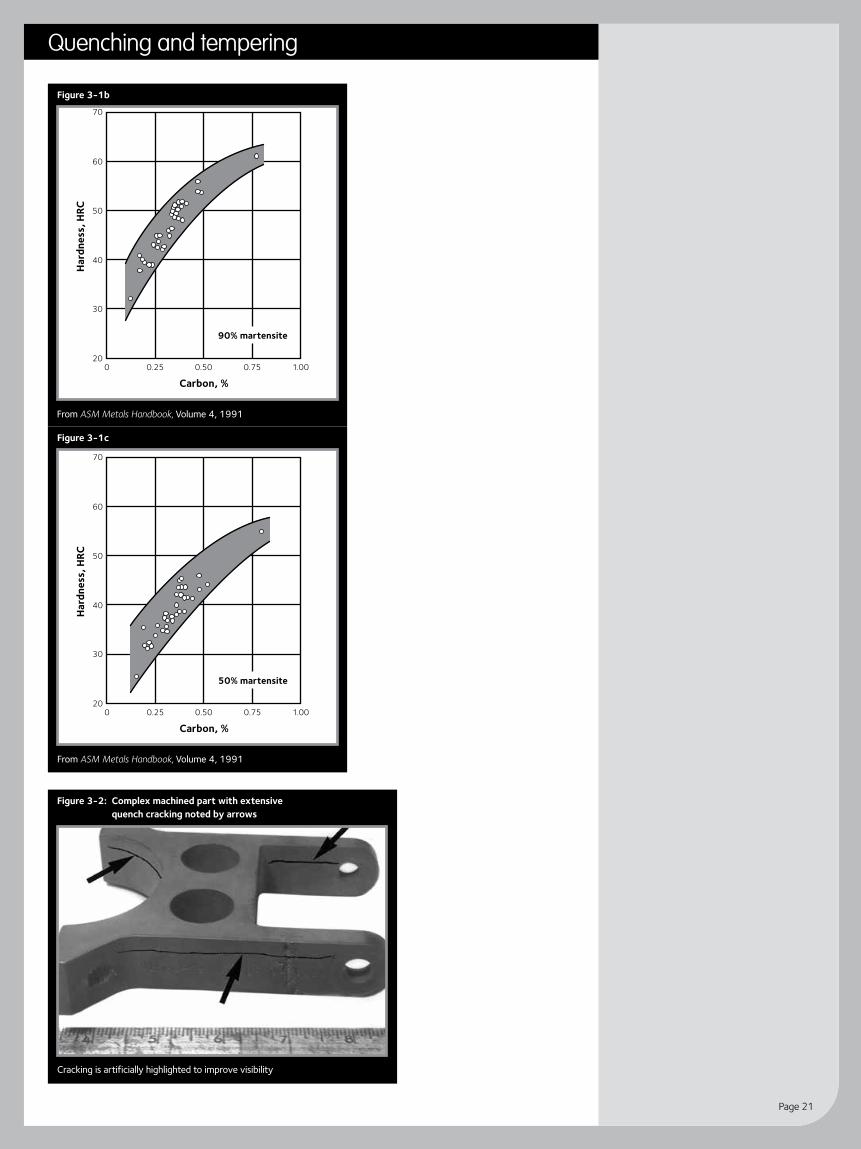
Appearance of quench cracksQuench cracking appears in a quenched and tempered part, either between the quenching and tempering operations or after tempering. Quench cracking is caused by the interaction of factors related to part design, heat treating and quenching practices. During the quenching of steel in oil or water, very high stresses are caused by nonuniform cooling, thermally induced deformation and the actual martensite phase transformation. Most often all three mechanisms must be considered to prevent quench cracking. As shown in Figure 3-1a to 3-1c, when the carbon level of steel increases, the hardness capable of being achieved increases. The martensite formed, while being harder, is more brittle and susceptible to cracking. The actual cracking takes place at notches, holes, slots, grooves or the plate centerline and may be in various orientations. An example is shown in Figure 3-2.
Carbon, %
Hard
ness
, HRC
20
30
50
40
60
70
0 0.25 0.50
99.9% martensite
0.75 1.00
Figure 3-1a: Relation of carbon content and percentage martensite to Rockwell C hardness
Heat treating of parts made from plate steel.
Quenching and temperingChapter 7
Page 21
Carbon, %
Hard
ness
, HRC
20
30
50
40
60
70
0 0.25 0.50
90% martensite
0.75 1.00
From ASM Metals Handbook, Volume 4, 1991
Figure 3-1b
Carbon, %
Hard
ness
, HRC
20
30
50
40
60
70
0 0.25 0.50
50% martensite
0.75 1.00
From ASM Metals Handbook, Volume 4, 1991
Figure 3-1c
Figure 3-2: Complex machined part with extensive quench cracking noted by arrows
Cracking is artificially highlighted to improve visibility
Quenching and tempering
Guidelines for fabricating and processing plate steel
Page 22
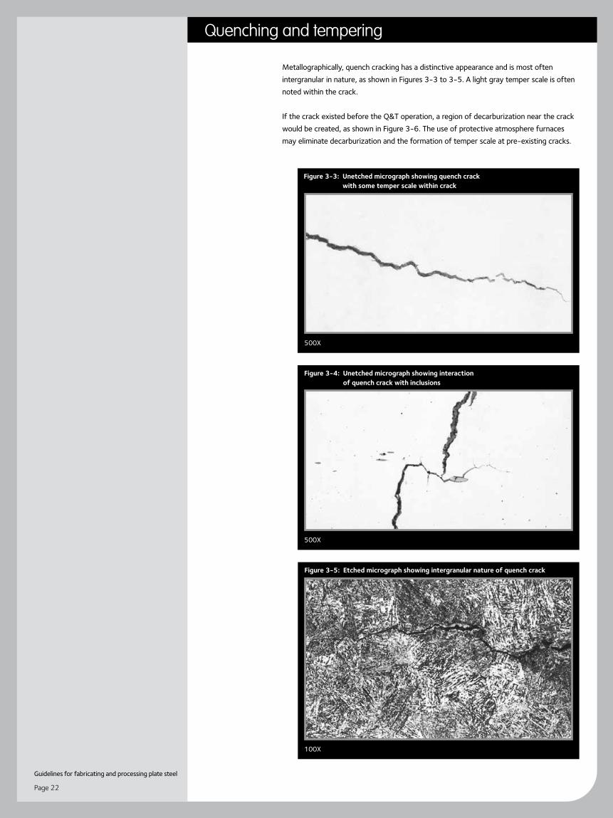
Metallographically, quench cracking has a distinctive appearance and is most often intergranular in nature, as shown in Figures 3-3 to 3-5. A light gray temper scale is often noted within the crack.
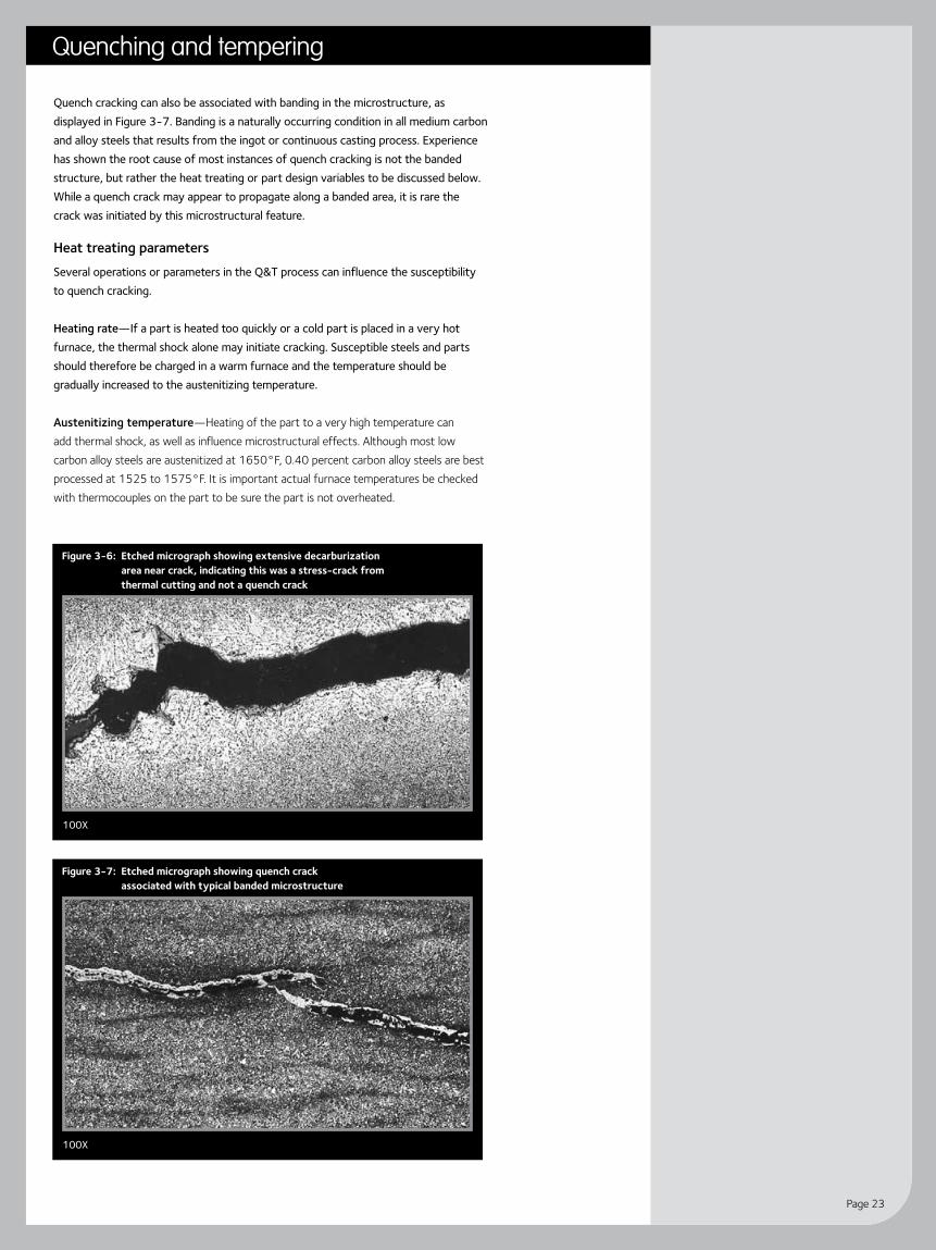
If the crack existed before the Q&T operation, a region of decarburization near the crack would be created, as shown in Figure 3-6. The use of protective atmosphere furnaces may eliminate decarburization and the formation of temper scale at pre-existing cracks.
500X
500X
Figure 3-3: Unetched micrograph showing quench crack with some temper scale within crack
Figure 3-5: Etched micrograph showing intergranular nature of quench crack
Figure 3-4: Unetched micrograph showing interaction of quench crack with inclusions
100X
Quenching and tempering
Page 23
Quench cracking can also be associated with banding in the microstructure, as displayed in Figure 3-7. Banding is a naturally occurring condition in all medium carbon and alloy steels that results from the ingot or continuous casting process. Experience has shown the root cause of most instances of quench cracking is not the banded structure, but rather the heat treating or part design variables to be discussed below. While a quench crack may appear to propagate along a banded area, it is rare the crack was initiated by this microstructural feature.
Heat treating parametersSeveral operations or parameters in the Q&T process can influence the susceptibility to quench cracking.
Heating rate—If a part is heated too quickly or a cold part is placed in a very hot furnace, the thermal shock alone may initiate cracking. Susceptible steels and parts should therefore be charged in a warm furnace and the temperature should be gradually increased to the austenitizing temperature.
Austenitizing temperature—Heating of the part to a very high temperature can add thermal shock, as well as influence microstructural effects. Although most low carbon alloy steels are austenitized at 1650°F, 0.40 percent carbon alloy steels are best processed at 1525 to 1575°F. It is important actual furnace temperatures be checked with thermocouples on the part to be sure the part is not overheated.
100X
Figure 3-6: Etched micrograph showing extensive decarburization area near crack, indicating this was a stress-crack from thermal cutting and not a quench crack
100X
Figure 3-7: Etched micrograph showing quench crack associated with typical banded microstructure
Quenching and tempering

Guidelines for fabricating and processing plate steel
Page 24
Quenching media—Whereas most 0.20 to 0.30 percent carbon steels may be successfully quenched in water, higher carbon steels need special liquid quench media, such as oil. Some additives are available for oil, which develop varying cooling rates from that of pure oil. Caution should be used, since some of these modified oils may approach water in cooling efficiency. Furthermore, the cooling rate can be slowed further by heating the quenching liquid. Hot oil quenches at 150°F have been found to be particularly useful for susceptible steels and parts.
The choice of quench media is a balancing act. The cooling rate must be quick enough to give the through-hardening needed for the part design, but not so severe as to cause cracking. Agitation of the quenching liquid is also important to provide uniform cooling. It is important the part has been thoroughly cooled to approximately 150°F and the metallurgical transformation has been completed.
Time to temper—After a part has been quenched, it must be tempered very soon thereafter. The significant residual stresses in an as-quenched part can cause cracking during the delay before tempering. Tempering acts as a stress relieving operation to reduce these stresses. Very susceptible steels or parts should be tempered within eight to 24 hours after quenching. If this is not possible, a “snap temper” at 400°F will stabilize a part until a final higher tempering temperature treatment can be performed.
Part designVery complex machined parts can be susceptible to quench cracking particularly in higher carbon steels. Often a small modification in the design of a part can reduce the problem.
Notches—Very sharp notches provide stress concentration where cracking can initiate. Well-radiused, gradual transitions in corners or slots are important (See Figure 3-8).
Groove
Cracked inHeat Treatment
Cutter Changed to ProduceRadius in Bottom of Keyway
From ASM Handbook, Volume 4, 1991
Figure 3-8: Grooves will cause a shaft to warp in heat treating (top). A keyway with sharp corners often initiates quench cracks (middle). This cracking is avoided by designing in a radius (bottom).
Quenching and tempering
Page 25
Changes in cross-sections—Even when significant radii are provided between changes in cross-section, cracking may still result. A very small section will cool much more rapidly than a larger one. This may require a complete part redesign or use of a new steel.
Holes—Whether threaded or not, holes are areas where non-uniform cooling takes place during quenching. Cracking may occur in the holes or in regions near them. To minimize these problems, packing the holes with an insulating material (Kaowool, mud, steel wool) will lead to more uniform cooling. If this is not acceptable then flush quenching of holes is advisable.
Orientation during quenching—When parts are immersed in the quenching liquid, they should be inserted in a manner that leads to a uniform cooling along the piece.
GeneralOther operations can also influence the susceptibility to cracking of quenched and tempered parts. For example, if chromium or nickel plating is performed after Q&T, hydrogen may be picked up in the steel which leads to cracking that looks like quench cracking. To prevent these problems, plated parts should be “baked” to remove the hydrogen.
More detailed discussions of the metallurgy and mechanics of quench cracking problems are presented in the literature. The ASM Handbook, Volume 4, is a particularly useful reference source.
Quenching and tempering
Guidelines for fabricating and processing plate steel
Page 26
Forming of ArcelorMittal USA steel
Cold, warm and hot forming are important processes used in the conversion of plate steel to useable parts and machinery. One of the critical properties of steel is ductility, which allows it to be shaped. There are, however, a wide variety of steel grades and forming processes that may be utilized. Therefore, guidelines for the safe and effective processing of plate steel are appropriate. The following guidelines were developed with particular emphasis on those practices that minimize the potential for cracking during the forming operation.
Cold formingCold forming is a term that applies to forming operations performed at ambient shop temperatures, typically 50–90°F. Cold forming is also referred to as roll forming, press brake bending and cold pressing. These processes can be performed on carbon, high-strength low-alloy, alloy, stainless and clad plate steel. Guidelines for these processes are presented in three areas.
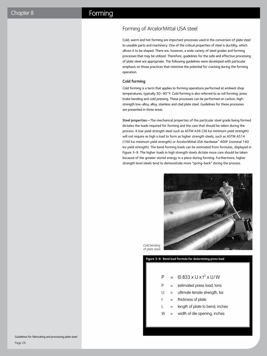
Steel properties—The mechanical properties of the particular steel grade being formed dictates the loads required for forming and the care that should be taken during the process. A low yield strength steel such as ASTM A36 (36 ksi minimum yield strength) will not require as high a load to form as higher strength steels, such as ASTM A514 (100 ksi minimum yield strength) or ArcelorMittal USA Hardwear® 400F (nominal 140 ksi yield strength). The bend forming loads can be estimated from formulas, displayed in Figure 3-9. The higher loads in high strength steels dictate more care should be taken because of the greater stored energy in a piece during forming. Furthermore, higher strength level steels tend to demonstrate more “spring-back” during the process.
Cold bending of plate steel.
P = (0.833 x U x t2 x L)/W
P = estimated press load, tons
U = ultimate tensile strength, ksi
t = thickness of plate
L = length of plate to bend, inches
W = width of die opening, inches
Figure 3-9: Bend load formula for determining press load
FormingChapter 8
Page 27
Steel ductility, measured as percent elongation in a tensile test, is also an important property. Higher tensile ductility levels allow more deformation during bending, particularly in the outer/tensile surface. Most often ductility decreases with increasing yield strength. Moreover, steel toughness, as measured by the Charpy V-Notch impact test, is useful in predicting cracking tendency during forming of plate. If a steel has sufficient toughness it will be more resistant to crack propagation from stress concentrations on the work-piece. Metallurgical processes such as heat treatment, low sulfur processing (including inclusion shape control) and fine grain practices can improve toughness and minimize cracking problems during forming. The benefits of forming at warmer shop temperatures is a result of the influence of toughness on formability. This will be discussed on page 29.
Plate characteristics—Specific characteristics of the actual plate being formed also influence its formability.
• Thickness—Thicker plates not only require increased forming loads, but also are more susceptible to cracking because of higher surface tensile stresses and typically lower toughness of thicker plates.
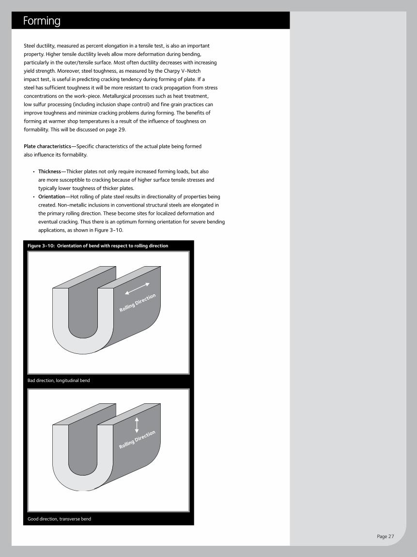
• Orientation—Hot rolling of plate steel results in directionality of properties being created. Non-metallic inclusions in conventional structural steels are elongated in the primary rolling direction. These become sites for localized deformation and eventual cracking. Thus there is an optimum forming orientation for severe bending applications, as shown in Figure 3-10.
Rolling Direction
Rolling Direction
Bad direction, longitudinal bend
Figure 3-10: Orientation of bend with respect to rolling direction
Rolling Direction
Rolling Direction
Good direction, transverse bend
Forming

Guidelines for fabricating and processing plate steel
Page 28
• Edge condition—A major cause of cracking during forming is the condition of the plate edge in the vicinity of the bend. An oxy-fuel gas-cut or plasma-cut edge has a hardened, low toughness heat affected zone (HAZ), which may initiate a crack during forming. The hardened edges should be removed by localized grinding or heat treatment. Even sheared plates may have a remnant, cold worked edge that should be removed by grinding. Figure 3-11 shows the approximate depths of the HAZ in oxygen cut edges. Figure 3-12 shows an example of an untreated gas-cut edge that cracked in the HAZ and led to failure of an A515 Grade 70 plate during forming.
• Surface condition—The surfaces of as-rolled and/or heat treated plates may have pits, scratches or gouges caused by processing or handling. The tensile/ outer surface in the vicinity of the bend should be inspected and gross defects smoothed out by grinding. Other surface conditions such as die stamps, arc strikes or areas where lifting lugs may have been attached would have similar concerns.
Forming practices—The techniques and equipment used in cold forming can have a significant influence on successful processing.
• Forming parameters—The design of the forming operation includes the radius of the punch and the geometry of the die, as demonstrated in Figure 3-13. Guidelines for forming of popular structural grades were developed by an AISI study. These results are summarized and published in ASTM A6 Appendix X4.
Thickness Oxy-fuel cut edge HAZ depth (inches)*
(inches) Low carbon steels High carbon steels Alloy steels
Under 0.5 Under 0.03125 0.03125 0.0625 and greater
0.5 0.03125 0.03125 to 0.0625 0.125 and greater
6 0.125 0.125 to 0.25 0.25 and greater
* Depth of hardened coarse grain HAZ is considerably less
Figure 3-12: Example of cracking in HAZ that lead to failure of bend
x
V-Die
Punch
R
W
T
Figure 3-13: Important parameters in bend forming
Punch bend forming severity ratio–R/T Die bend forming severity ratio–W/T
Figure 3-11: Approximate depths of heat affected zones in oxygen cut steels
Forming

Page 29
• Die conditions—If the surface of the female die is heavily gouged, smooth metal movement is inhibited. The surfaces of the V-die should be ground smooth. To further assist metal sliding over the V-die surfaces, lubrication may be utilized. Forming waxes and greases are available for these applications.
• Clad products—In severe cold forming applications for roll-bonded clad, a weld bead, tying in the two clad layers, will minimize the potential for separation of the layers.
Warm formingIncreasing the local or general temperature of the formed part can be helpful in difficult forming applications, as long as specific guidelines are followed. Warm forming is most often used to describe forming done at elevated temperatures that does not significantly change the properties of the base plate.
Reduced loads—Forming loads can be reduced if the temperature of the work-piece is increased to 900°F or higher. However, if the temperature used is too high, the strength and hardness of the base plate will be reduced. Refer to the mill test report for the heat treatment history of the plate. As a general guideline, do not heat as-rolled or normalized steels above 1050°F, and do not heat quenched and tempered steels to within 50°F of the mill tempering temperature. In the case of ArcelorMittal USA’s quenched and tempered Hardwear® steel, which is tempered at 400°F, a maximum forming temperature should be 350°F.
Reduced cracking—As was mentioned earlier, steel toughness is an important property to resist cracking during forming. Because ferritic steels go through a transition in toughness versus temperature, the effective toughness of a steel can be enhanced by increasing the temperature. This is shown schematically in Figure 3-14. Typically increasing the forming temperature to the range of 200–300°F can significantly improve the toughness of the steel and minimize certain cracking problems.
Hot formingWhen very thick plates must be formed, the required loads may be beyond machine capability. Hot forming allows a significant reduction in these loads because the typical temperatures used (1600–2000°F+), result in a major drop in the yield strengths of all steel products. However, exposure of the plate steel to these higher temperatures results in a significant change in the properties and microstructure of the base plate.
Steel chemistry—In very challenging hot-forming applications, the copper level in the steel is critical. A problem called “copper-checking” occurs in structural steels when the copper level is over 0.15 percent (and there is no matching nickel level). Susceptible applications include head spinning and “fluing” or swagging of nozzle openings in
Figure 3-14: Schematic CVN curve showing better toughness at higher temperatures.
Forming

Guidelines for fabricating and processing plate steel
Page 30
pressures vessels. Steels used in these applications should be ordered with a copper restriction of 0.15 percent maximum. An example of this problem is shown in Figure 3-15.
Forming practices—Because the plate steel is being heated to such a high temperature, there are several guidelines to observe.
• The uniformity of heating is very important. Also, care must be taken to make sure there is no direct impingement of the burner flame on the steel surface.
• Because the steel may be at high temperatures for a period of time, the atmosphere conditions in the furnace should be monitored (fuel/air ratios). Excessive localized oxidation of the steel can result in pitting of the steel surface.
Heat treatment of finished part—Because the properties of the base plate change during the hot forming operation, subsequent heat treatment of the formed part may be required.
• Normalizing—If the hot forming operation was intended to act as a normalizing heat treatment as well, the steel mill should have been requested to run a capability lab test on the plate. Use of the same heating temperature is important. Furthermore, a normalizing heat treatment requires air cooling after heating. Formed parts should not be stacked and should be positioned to allow uniform cooling. Sometimes fan cooling may be required to achieve the cooling rate necessary to achieve mechanical properties.
• Quenching and tempering—If a hot formed part must be quenched and tempered, the mill capability test heat treatment must be followed. A uniform
and effective water quench of the part is required. Water circulation and a large enough vessel to hold sufficient water are important. The water temperature should not exceed 100°F to ensure an effective quench. The tempering temperature and time must also be followed to assure achieving mechanical properties.
Figure 3-15: Nozzle openings showing Cu-checking problem
Forming

Page 31
Thermal cutting of ArcelorMittal USA steel
Thermal cutting, burning, or oxy-fuel cutting (OFC) of plate steel with an oxygen torch is a combination of oxidation and melting. Chemically produced intense heat is generated by the rapid oxidation of iron with a stream of high purity oxygen. This reaction is exothermic; that is, heat is given off as the combination takes place. The majority of the information in this chapter deals with OFC. Some guidelines are also provided for plasma and laser beam cutting.
Burning begins by heating a small portion of the plate surface to red hot (approximately 1600°F) with an oxy-fuel gas flame and directing a stream of high purity oxygen against it. Oxidation, or burning, begins almost instantly. The heat from the reaction is so intense that a considerable amount of adjacent metal is melted and flows away from the cutting slot, or kerf, with the oxidized material. This “slag” typically may contain 30 percent melted steel and 70 percent iron oxides (FeO, Fe2O3 and Fe3O4).
The conventional cutting torch is equipped with a tip that contains a cutting oxygen orifice surrounded by a ring of small oxy-fuel gas ports. A number of gases are commonly used for the oxy-fuel mix including acetylene, MPS, natural gas, propane and propylene. Flames from the oxy-fuel ports help initiate the cut, descale the plate, add heat to maintain cutting and shield the oxygen stream. After initiation of the reaction, the kerf cut through the plate section will continue to advance as long as the oxygen stream is supplied.
Cutting process parameters
For burning, one pound of iron requires 4.6 ft3 of oxygen. Oxygen consumption will vary depending on the quality of cut desired. For average straight line cutting of low carbon steel, consumption varies with the thickness of the plate and is lowest in the 4- to 5-inch range. The quantity of oxygen available for reaction decreases as it flows through the cut.
If oxygen flow is sufficient and properly directed—and, if cutting speed is not excessive—the cut face remains vertical and the rate of cutting will be approximately constant. If the cutting speed is too fast and/or oxygen flow is insufficient, the lower portion of the cut reacts slowly and “drag” marks become pronounced. A slower cutting speed increases the amount of heat retained and results in an improved q uality cutting edge. Various cutting tips are available depending on the plate thickness to be cut. Equipment manufacturers provide a suggested range of cutting speeds, as well as gas flow rates that should be used with their products.
During cutting, the heat from the process causes an area near the kerf to heat up to temperatures that cause metallurgical transformation of the steel. This heat-affected-zone (HAZ) is shown schematically in Figure 3-16. The depth of the HAZ is influenced
Oxy-fuel cutting of plate steel.
Thermal cutting Chapter 9

Guidelines for fabricating and processing plate steel
Page 32
by the cutting parameters (slower cutting speed results in a larger HAZ, but with lower hardness) and the grade of steel being cut. Figure 3-17 shows the effect of steel grade on the approximate depths of these HAZs. The quality of the HAZ (hardness, cracking) is influenced by cutting parameters and whether preheating and post heating are needed or were performed.
Preheating and post heatingWhen thermal cutting plate in certain combinations of thickness and chemical composition, special preheating and/or post-heating practices may be necessary. The use of preheating can:
• Increase the efficiency of the cutting operation by permitting increased travel speed and decreased consumption of oxygen and fuel gas.
• Decrease the migration of carbon to the cut surface by lowering the temperature gradient in the steel adjacent to the cut.
• Reduce or prevent hardening of the cut surface by reducing the cooling rate.• Reduce distortion.• Reduce thermally-induced stresses, thereby minimizing the formation of
thermal “stress-cracks.”
It is essential that preheat temperature be fairly uniform throughout the section in the area to be cut. Also, cutting should be started as soon as possible to take advantage of the heat in the plate. It is particularly important in thick plates to have the complete cross-section heated to the appropriate temperature. This is also important when bringing cold plates onto the fabrication floor when a nominal +50°F plate temperature is required. Figure 3-18 demonstrates a significant length of time can be required for a cold plate to warm-up to the +50°F minimum plate cutting temperature.
Thickness Oxy-fuel cut edge HAZ depth (inches)*
(inches) Low carbon steels High carbon steels Alloy steels
Under 0.5 Under 0.03125 0.03125 0.0625 and greater
0.5 0.03125 0.03125 to 0.0625 0.125 and greater
6 0.125 0.125 to 0.25 0.25 and greater
Directionof Cutting
Heat Affected Zone
KERF
2300
F
1800
F
1000
F
2800Fand
Greater
Figure 3-16: Schematic of thermal cutting process
Creation of a heat affected zone
* Depth of hardened coarse grain HAZ is considerably less
Figure 3-17: Approximate depths of heat affected zones in oxygen cut steels
Thermal cutting

Page 33
It is recommended all preheating be done in a furnace or on a special preheat table. If furnace or table capacity is not available, local preheating in the vicinity of the cut will be of some benefit. Local preheating may be accomplished by passing the cutting torch flames over the line of the cut until the desired preheat temperature is reached or by using a hand held torch. All local preheating should be done slowly and moderately to avoid high temperature gradients and additional thermal stresses.
Using a proper post heat treatment can eliminate most metallurgical changes caused by the cutting heat. These include tempering of hardened edges and relieving stresses at the cut edge. Post heat treatment should be performed in a furnace or by the use of special multiple flame heating torches as soon as possible after cutting.
Metallurgical influences on cut edge qualityThe need for special cutting practices, including preheating and post heating, to prevent the occurrence of hard cut edges or “stress-cracking,” are dictated by a number of parameters.
Carbon content—As carbon level increases the need for processing precautions increases.
Alloy level—As more alloy elements are added to a steel, the need increases.
Plate thickness—Thicker plates require special care.
Sulfur level—Steels with intentional additions of sulfur (free-machining) require more care.
Plate toughness—A plate in the as-rolled condition requires more care than after it is heat treated.
Part design—Parts with sharp corners or notches need care to prevent cracking.
Typically, a combination of two or more of these conditions dictates the need for additional care (preheating and post heating) when thermal cutting.
NOTE: When laying out ArcelorMittal USA mill edge plate for cutting, take measurements from the centerline of the plate to reliably establish area of good metal.
0
10
15
25
5
30
20
-10-20 0 10Temperature of Plate, F
12"12"
6"6"Ti
me
to H
eat-
up, H
ours
0
10
15
25
5
30
20
Time to Heat-up, Hours
20 30 40 50
Figure 3-18: Warm-up of plate to +50°F before cutting
6- and 12-inch thick plates at -20°F or +20°F Fabricating shop at +60°F
Thermal cutting

Guidelines for fabricating and processing plate steel
Page 34
Guidelines for thermal cuttingThe charts on pages 36 and 37 summarize ArcelorMittal USA’s recommended preheat and post heat practices for carbon, HSLA and alloy plate steel. These guidelines are based on a combination of steel carbon content, carbon equivalent, thickness and ArcelorMittal USA’s experience. Even these guidelines cannot ensure complete freedom from problems. Good shop thermal cutting practices are essential.
Further processing of thermal cut platesAfter thermal cutting plates or plate parts, further guidelines for consideration during subsequent processing are:
• If the grade and thickness requires post heat treatment for the part, the remaining usable plate “skeleton” may also need attention to prevent cracking in storage.
• If the cut edges are going to be part of a cold formed part, the tension corner of the edge and any notches should be ground prior to forming.
• If a saw cutting or machining operation will start at a thermally-cut edge, stress relief of the edge or starting of the cut with an abrasive saw may be needed to penetrate the hardened HAZ.
Plasma-arc cutting
Plasma-arc cutting (PAC) is a thermal-cutting process that uses a high temperature, high voltage constricted arc to melt material and high velocity gas to blow it away. Since its introduction in the 1950s, PAC has seen significant development, and with new technologies such as oxygen-PAC and improved equipment design, higher quality cuts and cutting speeds at lower operating costs have been achieved. As a result, more steel fabricators are using PAC, especially in the up to 1.5 inch thickness range. In this thickness range, PAC competes favorably with other thermal-cutting processes such as laser beam cutting (LBC) and OFC. The gases typically used to cut steel are nitrogen, air, carbon dioxide and oxygen.
Cut quality is influenced to a great extent by process variables and the PAC equipment should be operated and maintained strictly according to manufacturers’ recommendations. The most common material-related problems found during PAC are:
• Distortion.• Dross formation.
Distortion—can be minimized by:
• Ensuring the plate is free from residual stresses.• Employing a cutting sequence to distribute thermally
induced strains evenly.• Using a water shield or cutting under water.
Thermal cutting

Page 35
Dross formation—can be minimized by:
• Using oxygen plasma rather than nitrogen or air plasma.• Limiting Si content to less that 0.1 percent, if using nitrogen or air plasma.• Minimizing magnetic handling of the plates, to ensure low levels of
residual magnetism in the plate.
Laser beam cuttingLaser beam cutting (LBC) is a thermal-cutting process that removes material by locally melting (or vaporizing) with the heat from a laser beam, and using a gas jet to blow the molten or vaporized material away. Plain carbon and low alloy steels are most commonly cut using oxygen as the cutting gas and the exothermic reaction of iron with oxygen provides additional energy to enhance the cutting action. In the past, use of LBC was limited to steels of thickness 0.25 inch and less using laser power levels of 1.5 kW or less. With recent advances made in laser technology, higher laser power levels have been achieved and fabricators now cut 1 inch steel in production.
As with plasma-arc cutting, cut quality is significantly influenced by process variables and the equipment manufacturers’ recommendations should be strictly followed for operation and maintenance of the LBC system. Again like PAC, the most common material-related problems found during LBC are:
• Distortion.• Dross formation, poor cut edge quality.
Distortion—can be minimized by:
• Ensuring the plate is free from residual stresses.• Employing a cutting sequence to distribute thermally induced strains evenly.
Dross formation—is minimized and cut edge quality improved when:
• Surface scale is uniform and tightly adherent, and the surface is free from mechanical indentations (stamping, gouges, deep scratches), thick paint/thermal chalk markings and heavy rust.
• Si content is low (up to 0.04 percent).• Modest levels of Cu and Ni are present in the steel.• There is no gross segregation or large inclusions in the steel.
In most cases, hot-rolled steels are found to cut better in the as-rolled condition than the shot-blasted condition. However in some cases, heat-treated (quenched and tempered) steels give more consistent cuts in the shot-blasted condition. When shot blasting has to be carried out, using a smaller shot size provides more consistent cuts. Sand blasting is not recommended on plates to be laser cut.
Thermal cutting

Guidelines for fabricating and processing plate steel
Page 36
Popular ASTM specifications
Type Thickness (inches) A–Alloy ASTM C–Carbon +50°F minimum Preheat 300°F Preheat 300°F–gas cut hot specifications H–HSLA plate temperature1 gas cut hot immediately2 HT edges4
A36, A709-36 C 15 and under over 15 — A131 C 2 and under — — A202 A 2 and under — — A203 A 6 and under — — A204 A 4 and under — over 4 A225 A 6 and under — — A242 C 4 and under — — A283 C 15 and under over 15 — A284 C 12 and under — — A285 C 2 and under — — A299 C 2 and under over 2 —
A302 A 2 and under over 2–4 over 4 A353 A 2 and under — — A387–11, 12, 21, 22 A — 2 and under over 2 A387–5, 9, 91 A — 2 and under over 2 A455 C ¾ and under — —
A514–A, B, F&H (T-1™), P A 2.5 and under — — A514–E&Q (T-1C™) A 3 and under over 3 — A515 C 15 and under — — A516 C 15 and under — — A517–A, B, F&H (T-1™), P A 2.5 and under — — A517–E&Q (T-1C™) A 3 and under over 3 — A529 C 0.5 and under — — A533 A 2 and under over 2–4 over 4 A537 C 6 and under — — A542 A — 2 and under over 2 A543 (HY80, HY100) A 4 and under over 4 — A553 A 2 and under — — A562 A 2 and under — — A572, A709-50 H 3 and under over 3 — A573 C 1.5 and under — — A588, A709-50W, HPS 50W H 3 and under over 3 —
A612 C 1 and under — — A633 H 6 and under — — A656 H 3 and under — — A662 C 2 and under — — A678 H 6 and under — — A710 A 8 and under — — A724 C 2 and under — — A736 A 4 and under — — A737 H 6 and under — — A738 C 2.5 and under — — A808 H 3 and under — — A709-HPS 70W H 2 and under over 2 — A871 H 13⁄8 and under — —
Thermal cutting

Page 37
Clean-Cut™ 20 C 2 and under over 2 — C1119® C 2 and under over 2 — Clean-Cut™ 45 C — 1 and under over 14
C1144™ C — 1 and under over 14
BethStar™ H 3 and under — —
Spartan™, HSLA 80/100 A 8 and under — — MTD® 1 A — 1 and under over 14
MTD® 2 A — 1 and under over 14
MTD® 3 A — — all thicknesses4
MTD® 4 A — — all thicknesses4
Hardwear® 400F A 2 and under over 2–3 — Hardwear® 500F A 1 and under over 1–3 — T-1™ Abrasion Resistant A 20.5 and under over 20.5 — MIL-A-12560 A 20.5 and under over 20.5 — MIL-A-46100 A 1 and under over 1–2 —
Popular ASTM chemistry only grades
Type Thickness (inches) A–Alloy ASTM C–Carbon +50°F minimum Preheat 300°F Preheat 300°F – gas cut hot A830 grades H–HSLA plate temperature1 gas cut hot immediately2 HT edges
1006–1025 C 15 and under — — 1030 C 8 and under over 8 — 1040 C — 1 and under over 13
1045 C — 1 and under over 13
1060 C — — all thicknesses3
ASTM A829 Grades
4130 A 1.5 and under 1.5 to 6 over 63
4140 A — 1 and under over 13
4142 A — 1 and under over 13
4150 A — all thicknesses3
E4340 A — — all thicknesses3
E6150 A — — all thicknesses3
8615 A 8 and under — — 8617 A 8 and under — — 8620 A 8 and under — — 8625 A 8 and under — — 8630 A — 2 and under over 23
ArcelorMittal USA Proprietary Grades
Notes: Recommended practices are based on Tables 10 and 11, Iron and Steel Society Steel Products Manual—Plates, and/or ArcelorMittal USA’s experience.
1. When preheating is not required, plates should be at a temperature of at least 50°F. (During winter months, plates brought in from outside storage may require several days to warm up, depending on thickness).
2. Edges must be heat treated (HT) immediately after cutting to soften the edges. If unable to heat treat edges immediately, material must be kept hot until heat treated.
3. Heat to 1100°F/1325°F, hold 0.5 hr./in., air cool. An anneal or sub-critical anneal may be substituted.
4. Heat to 1050°F ± -25°F, hold 0.5 hr./in., air cool.
Thermal cutting

Guidelines for fabricating and processing plate steel
Page 38
Welding of ArcelorMittal USA steel
Dealing with hydrogen-assisted cold crackingWelding is of critical importance in the fabrication of structures from plate steel. Most popular structural steels are readily weldable with well-established shop practices and welding materials. However, under a combination of circumstances—including the grade of steel, welding consumables being used, weld joint design or environmental conditions—cracking of weldments may occur. A popular way to identify a potentially susceptible grade of steel is to calculate a carbon equivalent and refer to a diagram such as that shown in Figure 3-19. However, this is at best only a first step in dealing with a welding situation where susceptibility to weld cracking is of concern. There are numerous reference sources for guidance in the welding of steels, four of which are noted at the end of this chapter. In this chapter, we focus on dealing with hydrogen-assisted weld cracking problems that are most frequently encountered in welding of structures fabricated from plate steel.
Cracking in WeldmentsCracks occur in the weld and base metal of fabricated weldments when localized stresses exceed the ultimate strength and/or toughness of the material. These cracks may be in the longitudinal or transverse direction with respect to the weld axis and generally are divided into two categories:
0
.40
.30
.20
.10
.30 .40 .50 .60 .70 .80 .90
*High Strength Welding Consumables May Require Additional Care
CE = C +Mn+Si Ni+Cu Cr+Mo+V
+6 15 5+
Zone IIDepends onConditions
Typical Chemistries
Zone I*Safe Under
Most Conditions
Zone IIIHigh Under
All Conditions
Carb
on, %
A516-70
A710
A572-50 A514FA387-22
A36
Figure 3-19: Influence of carbon level and carbon equivalent on susceptibility to hydrogen-assisted HAZ cracking of plate steel
From Graville
Welding of plate steel.
WeldingChapter 10

Page 39
Weld MetalWeld Metal
HAZHAZ
Figure 3-20: Weldment terminology
ToeCrack
Root Crack
Toe Crack
Root Crack
TransverseCracks
TransverseCracks
Figure 3-21: Weldment terminology and types of cracks
Toe and root cracks
Transverse cracks
Hot cracks develop at elevated temperatures, i.e. they commonly form during solidification of the weld metal.
Cold cracks, or “delayed” cracks, develop after solidification of the fusion zone as the result of residual stresses. Cold cracks generally form at some temperature below 200°F (93°C), sometimes several hours, or even days, after welding. The time delay depends upon the grade of steel, magnitude of welding stresses and the hydrogen content of the weld and heat-affected zone (HAZ).
Delayed cracking normally is associated with dissolved hydrogen and can occur in the weld metal, generally when filler metals with high yield strength levels are used, or in the heat-affected zone of the base metal due to diffusion of hydrogen from the weld metal to the base metal during the welding process (Figure 3-20). Examples of typical delayed cracks, as in Figures 3-21 and 3-22, include:
• Toe cracks which are generally cold cracks that initiate approximately normal to the base metal surface and then propagate from the toe of the weld where the residual stresses are higher. These cracks are generally the result of thermal shrinkage strains acting on a weld heat-affected zone that has been embrittled. Toe cracks sometimes occur when the base metal cannot accommodate the shrinkage strains that are imposed by welding.
Welding

Guidelines for fabricating and processing plate steel
Page 40
• Root cracks, which run longitudinally, originate in the HAZ of the root of the weld.• Transverse cracks are nearly perpendicular to the weld axis. They may
be limited entirely to the weld metal or may propagate from the weld metal into the heat-affected-zone and the base metal. Transverse cracks are normally related to hydrogen embrittlement.
• Underbead cracks are generally cold cracks that form in the heat-affected zone. They may be short and discontinuous, or may extend to form a continuous crack. Usually found at irregular intervals under the weld metal, they do not always extend to the surface.
The occurrence of any of the aforementioned cracking requires hydrogen in solid solution, a crack susceptible microstructure and high residual stresses.
Hydrogen can be absorbed from the atmosphere in large amounts by carbon and alloy steels at the elevated temperatures associated with welding. As the steel cools, it retains less and less hydrogen in solution and “rejects” the excess hydrogen. When steel is held at elevated temperatures or slow cooled, hydrogen atoms can escape back into the atmosphere by the process known as diffusion. However, rapid cooling, associated with most welding processes, tends to “trap” the hydrogen, where it acts to embrittle and weaken the steel structure. A greater potential for cracking exists in a brittle material (high-strength, high-hardness) subjected to high residual stresses (restrained joints).
The ability of a steel to form the hard metallurgical constituent known as martensite or other hard phases is, in general, dependent on the carbon equivalent (CE) of the steel and the cooling rate imposed upon it in cooling from the transformation temperature. The higher the CE and the faster the cooling rate, the higher the tendency for hard, brittle phases to form during cooling. Since the metallurgical characteristics of the base metal can influence heat-affected zone crack susceptibility and these characteristics are determined, in large part, by the steel’s chemistry, small changes in chemical composition of the base and filler metals (hydrogen content) can appreciably increase cracking tendency. And, since steel is melted to a composition range, there can be a significant difference in crack susceptibility between plates produced from several heats of the same steel grade.
In the welding of plate steel, the plate acts as a giant “heat sink” and actually “sucks” heat away from the weld. The thicker the plates and more complex the design of the weld joint, the bigger the heat sink, the faster the cooling rate, and the greater the tendency to form martensite. These factors also lead to the formation of higher residual stresses in the weldment and, when combined with a restrained joint, can significantly increase the susceptibility for cracking.
Underbead Cracks
Figure 3-22: Weldment terminology and types of cracks
Underbead cracks
Welding

Page 41
Sources of hydrogen in weldingDuring the welding process, hydrogen can enter the molten weld pool from a variety of sources. These sources include:
• Moisture, oil, grease, rust or scale on the base metal surfaces.• Moisture in the atmosphere (rainy or humid days), which allows infiltration
of moisture into the shielding atmosphere surrounding the arc zone.• Moisture in the electrode coating or core ingredients of flux-core wire.• Hydrogen from cellulose in the flux or electrode coatings.• Moisture in the flux of submerged arc welding.• Drawing lubricant or protective coatings on bare wire or flux-core wire.
Minimizing hydrogen damageHydrogen damage (cracking) can be minimized by establishing and enforcing welding practices and procedures that prevent excess hydrogen from entering the weld puddle and by taking steps that permit any dissolved hydrogen to diffuse out slowly. Typical methods to achieve this include:
1. Thorough cleaning of the base metal (weld joint and adjacent area) by grinding and brushing.
2. Exclusive use of low hydrogen electrodes and/or low hydrogen welding processes.3. Proper drying and storing of welding electrodes, fluxes and gases and proper
maintenance of equipment such as wire feeders.4. Welding procedures that lower welding stresses.5. Employing a combination of welding and thermal treatments that promote
the escape of hydrogen by diffusion. This also can modify the microstructure to make it more resistant to hydrogen cracking.
• Preheating and maintaining minimum interpass temperature.• Slow cooling or maintaining preheat after welding.• Post-weld heat treatment.
Low hydrogen welding practicesElectrodes—All electrodes having low hydrogen coverings should be purchased in hermetically sealed containers. Immediately after opening, electrodes should be stored in a ventilated oven held at 250°F (121°C) minimum. After containers are opened or after electrodes are removed from the holding oven, electrode exposure to the atmosphere should not exceed supplier recommendations. The following maximums are provided for reference:
• Electrodes exposed to the atmosphere for longer time periods should not be used unless they have been rebaked. Wet electrodes should be discarded.
• Electrodes should be rebaked no more than once.
Carbon steel Alloy steel
E70XX 4 hrs. E70XX-X 4 hrs.
E70XXR 9 hrs. E80XX-X 2 hrs.
E70XXHZR 9 hrs. E90XX-X 1 hr.
E7018M 9 hrs. E100XX-X 0.5 hr.
E110XX-X 0.5 hr.
Exposure maximums
Welding

Guidelines for fabricating and processing plate steel
Page 42
• Carbon electrodes should be rebaked at 500–800°F (260–427°C) for a minimum of two hours.
• Alloy electrodes should be rebaked at 700–800°F (371–427°C) for a minimum of one hour.
• Electrodes of any classification lower than E100XX-X (except E7018M and E70XXH4R) used for welding high strength plate steel, such as ASTM A514, A517 & A709-100 & 100W, should be baked before use at 700–800°F (371–427°C) for a minimum of one hour, regardless of how the electrodes are furnished.
Bare wire and flux core wire—Remove oil, grease, drawing compound and dirt from the bare wire or flux core wire.
Flux—New fluxes are available that allow weld deposits with low hydrogen levels (less than 5 ml/100 g). These are particularly useful with higher strength alloy electrodes.
• Flux for SAW should be dry and free of contamination from dirt, mill scale or other foreign material.
• Flux should be purchased in packages that can be stored for at least six months, under normal conditions, without affecting its welding characteristics or weld properties.
• Flux from a damaged package should be discarded or dried before use in a ventilated oven, using supplier recommendations; generally baking at 700–800°F (371–427°C) for a minimum of one hour.
• Flux should be placed in dispensing system immediately upon opening a package.
• When using flux from an open package, the top one inch should be discarded.• Flux that becomes wet should be discarded.• Clean, unfused, reclaimed flux should be dried as described above before reuse.
Preheat—Even with all the controls described above for minimizing hydrogen in the consumables, high carbon steels (over 0.30 percent C), alloy steels, high-strength steels (100 ksi/690 MPa yield strength and above), thick plates (over 1 inch or 25 mm) or highly-restrained weldments may require preheat to prevent cracks or fissures due to hydrogen. The primary purpose of preheat is to retard the cooling rate in the heat-affected zone and weld metal. In multi-bead welds, subsequent beads may be deposited on metal that has been preheated by preceding beads, but the first and most important bead is deposited on cold steel unless a preheating procedure is adopted. Preheating has the advantages of:
• Drying the joint of any retained moisture.• Burning off any organic compounds.• Increasing the diffusion rate of hydrogen.• Slowing the weldment cooling rate.
Calculations have established the cooling rate from a preheated plate temperature of 200°F (93°C) is only 85 percent the rate from a plate at the ambient temperature of 75°F (24°C). It is 70 percent for a 300°F (149°C) preheat. This slower cooling rate modifies the heat-affected zone microstructure to make it more crack resistant and lowers the level of residual stresses in the weldment.
Preheating temperatures used are based on experience or codes, such as the AWS D1.1 and D1.5. Typically, shop ambient temperatures of 50–60°F (10–16°C) are appropriate to some thickness. The preheat temperatures should then increase with thickness, for example, 150°F (66°C), 225°F (107°C), 300°F (149°C). For high carbon and high alloy steels, preheating temperatures as high as 600°F (360°C) may be required. Furthermore, the higher residual stresses that result with certain joint
Welding

Page 43
designs and higher strength welding consumables may require higher preheats to avoid delayed cracking even for carbon steels that usually require minimal preheat.
Methods for preheating—The preheat method used is also important. Preheating may be applied in several fashions, with oxy-fuel (rosebud) torches being one of the most common. Various types of electric resistance heaters or blankets are also available.
One of the by-products of combustion is moisture. When a flame is applied to cold steel, condensation usually occurs in the region. It is important to drive this moisture (“chase the chill”) from the weld zone. Also, flame preheating from only one side of the plate may cause condensation on the opposite side of the joint, causing moisture to be picked up in the first, or “root,” pass.
Preheat temperature measurement can be accomplished in several ways, the most common being the use of Tempil sticks (crayons that melt at the prescribed temperature). It is important to remember the proper preheat temperature has not been reached and the steel is not ready to weld until the Tempil sticks melt at a minimum distance of 3 inches on either side of the joint, as well as the back side.
Once welding begins, the weld joint should not be allowed to cool below the preheat temperature (now the minimum “interpass” temperature) until the welding is complete. If the welding operation is interrupted for any reason, the above preheating operation should be repeated until the minimum preheat temperature is re-established.
Slow cooling and post-weld heat treatmentThe same thick, high-strength restrained weldments that require preheat may also require slow cooling and/or post-weld heat treatment (PWHT). Again, this preheat/ post heat combination serves the purpose of reducing residual stresses, allowing the diffusion of dissolved hydrogen and modifying the microstructure of the heat affected-zone to render it more crack resistant.
The most common methods of slow cooling involve maintaining minimum preheat temperature on the joint for several hours after the welding has been completed and/or wrapping the completed weldment with an insulating blanket to retard the cooling rate.
While the preheat and slow cool methods described above help in reducing the formation of martensite, a certain amount is unavoidable in thick, high CE steels. In these instances, post-weld heat treatment (PWHT) may be necessary. PWHT, also known as “stress relieving” or “tempering,” is usually accomplished by heating the weldment to a temperature below its tempering temperature or other temperature which may affect the base metal properties. However, for PWHT to be of value in reducing hydrogen in the weldment it must be performed immediately after the weld has begun to cool. Other critical aspects of any PWHT include:
• Temperature of the furnace for charging the weldment.• Heat up rate.• PWHT temperature and range.• Hold time at temperature.• Cooling rate.
Applicable codes and specifications, job requirements and qualification test requirements generally govern the specific PWHT cycle selected. Some steels, such as ASTM A514 and A710, can be embrittled by PWHT. It is recommended the choice of PWHT be made only after review by a welding engineer.
More specific welding informationChapters 11 and 12 provide more detailed welding information for popular structural and pressure vessel plate steels.
Welding

Guidelines for fabricating and processing plate steel
Page 44
ReferencesThe following references are excellent resources for additional information on the welding of steels.
1. R. D. Stout. Weldability of Steels, 4th edition, Welding Research Council, New York, NY, 1987.
2. ASM International. ASM Handbook, Volume 6, Welding, Brazing and Soldering, Materials Park, OH, 1993.
3. American Welding Society. D1.1–96, 1996, Structural Welding Code–Steel, Miami, FL, 1996.
4. American Welding Society. D1.5–96, 1996, Bridge Welding Code, Miami, FL, 1996.
Welding

Page 45
Welding and other data are provided for structural and pressure vessel plate steel grades. This information includes welding electrode and preheat guidelines, and typical carbon equivalent levels. This welding information may be more stringent than AWS D1.1. Furthermore, although some grades may be welded with other than low hydrogen practices, ArcelorMittal USA recommends use of low hydrogen welding practices for all plate steel welding. Also provided are available Charpy V-Notch levels that can be ordered and, where available, typical stress-strain curves and atmospheric corrosion data. Please refer to ArcelorMittal USA if additional data is desired.
Structural plate steelPlate steel grades produced following ASTM A6 general requirements
Pressure vessel plate steelPlate steel grades produced following ASTM A20 general requirements
Welding and other data

Guidelines for fabricating and processing plate steel
Page 46
Welding and other data on structural plate steel grades
Structural grades
Grade Page number Grade Page number
A36 47 A633 55
A242 48 A656 56
A283 49 BethStar™ 57
A514 50 A678 58
A529 51 A710 59
A572 52 A808 60
A573 53 A871 61–62
A588 54 Hardwear® 63
Structural plate steelChapter 11

Page 47
DescriptionSpecification covers plates, shapes and bars. Only data applicable to plates is shown. This specification, which describes an as-rolled plate steel grade, is approved for use by the Department of Defense.
Year introduced1960
Special featuresThis specification permits the addition of copper to enhance corrosion resistance. A special paragraph relating to the use of this grade for bridge base plates is included in the specification. If the plate is used for this purpose, refer to the specification for more information.
Normal usesA popular “workhorse” grade, it is used widely for various applications. For bridges, this grade is specified as A709 Grade 36.
Impact toughnessImpact toughness requirements are not included in the basic specification, but can be added as a supplementary requirement. ArcelorMittal USA can furnish the Charpy values shown on this sheet at extra charge. Additional requirements such as deoxidation practice, modified chemistry, special rolling or heat treatment may be necessary to achieve the properties.
Special notesThis grade is available with Integra® or Fineline™ quality to achieve improved properties.
Standard specification for carbon structural steel
Welding dataSuggested welding consumables for arc welding processes
Manual shielded Submerged- Gas Flux Notes metal-arc arc metal-arc cored-Arc low hydrogen
E70xx, E70xx-x F6xx-Exxx, ER70S-x E6xT-x, F7xx-Exxx, E7xT-x except F7xx-Exx-xx -2, -3, -10, -GS
Suggested minimum preheat and interpass temperature for arc welding
Thickness Manual shielded Submerged-arc Notes (inches) Metal-arc Gas metal-arc Low hydrogen Flux cored-arc
Up to ¾ incl None* None*
Over ¾ to 10.5 incl 70°F 70°F
Over 10.5 to 20.5 incl 150°F 150°F
Over 20.5 225°F 225°F
Preheat and interpass temperatures to prevent hydrogen-assisted cracking depend on specific welding conditions and restraint level associated with joint configuration. This table should only be used as a guide for preheat and interpass temperatures. In general, the listed temperatures are similar to those published in the AWS Structural Welding Code, D1.1.
Welding carbon equivalent =
C + Mn + Cr + Mo + V + Ni + Cu 6 5 15
The carbon equivalent range shown in the table is based on heat analysis. It is the range most commonly produced for plates by ArcelorMittal USA. Individual plates or heats may have carbon equivalents beyond the range in the table. See Chapter 10, page 38, regarding the significance of carbon equivalent.
Shaded area denotes availability of A36 plate with Charpy15 ft-lb longitudinal impact toughness at various temperatures
Temp. +70°F +40°F +10°F 0°F -20°F -30°F -50°F Thickness (inches)
Up to 4 incl
Over 4 to 8 incl
Over 8 to 12 incl
Only low hydrogen electrodes shall be used when welding A36 more than 1 in. (25.4 mm) thick for dynamically loaded structures.
* When the base metal temperature is under 32°F, preheat the base metal to at least 70°F and maintain this temperature during welding.
Thickness TypicaliInches) carbon equivalent values
Up to 10.5 incl 0.33 to 0.37
Over 10.5 to 20.5 incl 0.35 to 0.39
Over 20.5 to 15 incl 0.38 to 0.42
Stress vs. strain curve—tensile coupon Typical industrial atmospheric corrosion data
A representative stress vs. strain curve for a typical 8 in. gauge tensile coupon.
Structural plate steel A36
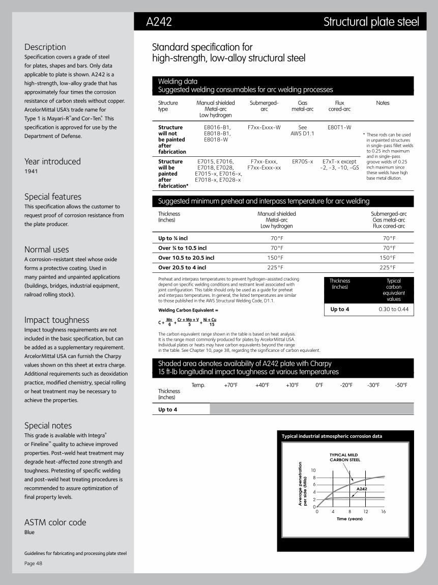
Guidelines for fabricating and processing plate steel
Page 48
Typical industrial atmospheric corrosion data
DescriptionSpecification covers a grade of steel for plates, shapes and bars. Only data applicable to plate is shown. A242 is a high-strength, low-alloy grade that has approximately four times the corrosion resistance of carbon steels without copper. ArcelorMittal USA’s trade name for Type 1 is Mayari-R™and Cor-Ten®. This specification is approved for use by the Department of Defense.
Year introduced1941
Special featuresThis specification allows the customer to request proof of corrosion resistance from the plate producer.
Normal usesA corrosion-resistant steel whose oxide forms a protective coating. Used in many painted and unpainted applications (buildings, bridges, industrial equipment, railroad rolling stock).
Impact toughnessImpact toughness requirements are not included in the basic specification, but can be added as a supplementary requirement. ArcelorMittal USA can furnish the Charpy values shown on this sheet at extra charge. Additional requirements such as deoxidation practice, modified chemistry, special rolling or heat treatment may be necessary to achieve the properties.
Special notesThis grade is available with Integra® or Fineline™ quality to achieve improved properties. Post-weld heat treatment may degrade heat-affected zone strength and toughness. Pretesting of specific welding and post-weld heat treating procedures is recommended to assure optimization of final property levels.
ASTM color codeBlue
Standard specification for high-strength, low-alloy structural steel
Welding dataSuggested welding consumables for arc welding processes
Structure Manual shielded Submerged- Gas Flux Notes type Metal-arc arc metal-arc cored-arc Low hydrogen
Structure E8016-B1, F7xx-Exxx-W See E80T1-W will not E8018-B1, AWS D1.1 be painted E8018-W after fabrication
Structure E7015, E7016, F7xx-Exxx, ER70S-x E7xT-x except will be E7018, E7028, F7xx-Exxx-xx -2, -3, -10, -GS painted E7015-x, E7016-x, after E7018-x, E7028-x fabrication*
Suggested minimum preheat and interpass temperature for arc welding
Thickness Manual shielded Submerged-arc (inches) Metal-arc Gas metal-arc Low hydrogen Flux cored-arc
Up to ¾ incl 70°F 70°F
Over ¾ to 10.5 incl 70°F 70°F
Over 10.5 to 20.5 incl 150°F 150°F
Over 20.5 to 4 incl 225°F 225°F
Preheat and interpass temperatures to prevent hydrogen-assisted cracking depend on specific welding conditions and restraint level associated with joint configuration. This table should only be used as a guide for preheat and interpass temperatures. In general, the listed temperatures are similar to those published in the AWS Structural Welding Code, D1.1.
Welding Carbon Equivalent =
C + Mn + Cr + Mo + V + Ni + Cu 6 5 15
The carbon equivalent range shown in the table is based on heat analysis. It is the range most commonly produced for plates by ArcelorMittal USA. Individual plates or heats may have carbon equivalents beyond the range in the table. See Chapter 10, page 38, regarding the significance of carbon equivalent.
Shaded area denotes availability of A242 plate with Charpy15 ft-lb longitudinal impact toughness at various temperatures
Temp. +70°F +40°F +10°F 0°F -20°F -30°F -50°F Thickness (inches)
Up to 4
* These rods can be used in unpainted structures in single-pass fillet welds to 0.25 inch maximum and in single-pass groove welds of 0.25 inch maximum since these welds have high base metal dilution.
Thickness Typical (inches) carbon equivalent values
Up to 4 0.30 to 0.44
A242 Structural plate steel

Page 49
DescriptionSpecification covers four grades of steel for plates, shapes and bars. Only data applicable to as-rolled plate steel grades is shown.
Year introduced1946
Special featuresThis specification permits the addition of copper to enhance corrosion resistance.
Normal usesAn inexpensive “utility” grade of steel used widely in many non-demanding applications.
Impact toughnessImpact toughness requirements are not included in the basic specification, but can be added as a supplementary requirement. ArcelorMittal USA can furnish the Charpy values shown on this sheet at extra charge. Additional requirements such as deoxidation practice, modified chemistry, special rolling or heat treatment may be necessary to achieve the properties.
Special notesThis grade is available with Integra® or Fineline™ quality to achieve improved properties.
ASTM color code Grade: D—Orange
Standard specification for low and intermediate tensile strength carbon steel plates
Welding dataSuggested welding consumables for arc welding processes
Grade Manual shielded Submerged- Gas Flux Metal-arc arc metal-arc cored-arc Low hydrogen
A, B, C, D E70xx, F6xx-Exxx, ER70S-x E6xT-x, E70xx-x F7xx-Exxx, E7xT-x except F7xx-Exx-xx -2, -3, -10, -GS
Suggested minimum preheat and interpass temperature for arc welding
Grade Thickness Manual shielded Submerged-arc Notes (inches) Metal-arc Gas metal-arc Low hydrogen Flux cored-arc
A, B, Up to ¾ incl None* None* C, D Over ¾ to 10.5 incl 70°F 70°F Over 10.5 to 20.5 incl 150°F 150°F Over 20.5 225°F 225°F
Preheat and interpass temperatures to prevent hydrogen-assisted cracking depend on specific welding conditions and restraint level associated with joint configuration. This table should only be used as a guide for preheat and interpass temperatures. In general, the listed temperatures are similar to those published in the AWS Structural Welding Code, D1.1.
Welding carbon equivalent =
C + Mn + Cr + Mo + V + Ni + Cu 6 5 15
The carbon equivalent range shown in the table is based on heat analysis. It is the range most commonly produced for plates by ArcelorMittal USA. Individual plates or heats may have carbon equivalents beyond the range in the table. See Chapter 10, page 38, regarding the significance of carbon equivalent.
Shaded area denotes availability of A283 plate with Charpy15 ft-lb longitudinal impact toughness at various temperatures
Temp. +70°F +40°F +10°F 0°F -20°F -30°F -50°F Thickness (inches)
Up to 4
Over 4 to 18 incl
Over 8 to 12 incl
Grade Thickness Typical (inches) carbon equivalent values
A Up to 15 0.12 to 0.18
B Up to 15 0.15 to 0.25
C Up to 15 0.17 to 0.29
D Up to 15 0.24 to 0.37
Stress vs. strain curve—tensile coupon Typical industrial atmospheric corrosion data
A representative stress vs. strain curve for a typical 8 in. gauge tensile coupon.
* When the base metal temperature is under 32°F, preheat the base metal to at least 70°F and maintain this temperature during welding.
Structural plate steel A283

Guidelines for fabricating and processing plate steel
Page 50
Stress vs. strain curve—tensile coupon Typical industrial atmospheric corrosion data
Welding dataSuggested welding consumables for arc welding processes
Thickness Manual shielded Submerged- Gas Flux Notes (inches) Metal-arc arc metal-arc cored-arc Low hydrogen
Up to E11015-x, E11016-x, F11xx-Exx-xx ER110S-x E11xTx-x 20.5 incl E11018-x
Over 20.5 E10015-x, E10016-x, F10xx-Exx-xx ER100S-x E10xTx-x E10018-x
Deposited weld metal shall have a minimum impact strength of 20 ft-lb (27.1J) at 0°F (-18°C) when Charpy V-Notch specimens are required.
Suggested minimum preheat and interpass temperatures for welding
Thickness Produced to Produced to minimum brinell hardness (inches) A514 tensile properties requirements for abrasion resistant applications
Up to ¾ incl 50°F 100°F
Over ¾ to 10.5 incl 125°F 150°F
Over 10.5 to 20.5 incl 175°F 200°F
Over 20.5 225°F 250°F
A preheat or interpass temperature above the minimum shown may be required for highly restrained welds—preheat or interpass temperatures should not exceed 400°F for thicknesses up to 1.5 inch or 450°F for thicknesses over 1.5 inch.
Welding carbon equivalent =
C + Mn + Cr + Mo + V + Ni + Cu 6 5 15
The carbon equivalent range shown in the table is based on heat analysis. It is the range most commonly produced for plates by ArcelorMittal USA. Individual plates or heats may have carbon equivalents beyond the range in the table. See Chapter 10, page 38, regarding the significance of carbon equivalent.
Shaded area denotes availability of A514 plate with Charpy15 ft-lb longitudinal impact toughness at various temperatures
Temp. +70°F +40°F +10°F 0°F -20°F -30°F -50°F Thickness (inches)
Up to 6
Grade Thickness Typical (inches) carbon equivalent values
A Up to 1.25 0.45 to 0.55
B Up to 1.25 0.40 to 0.53
E Up to 6 0.70 to 0.80
F Up to 2.25 0.50 to 0.60
H Up to 2 0.50 to 0.60
P Up to 4 0.60 to 0.70
Q Up to 6 0.75 to 0.85
Standard specification for high yield strength, quenched and tempered alloy steel plate, suitable for weldingThis specification permits varied chemistries called Grades A, B, C, E, F, H, J, K, M, P, Q, R, S and T. (ArcelorMittal USA makes only ASTM A514 Grades A, B, E, F, H, P and Q.)
DescriptionSpecification covers a grade of steel for plates. It is an alloy steel grade, fully killed, fine grain (ASTM Number 5 or smaller). It is heat treated by quenching and tempering. The heat treating temperatures are reported on the test certificates. The specification permits 14 compositions, of which ArcelorMittal USA produces Grades A, B, D, E, F, H, P and Q. The specification is approved for use by the Department of Defense. The pressure vessel version of this specification is A517.
Year introduced1964
Special featuresA quenched and tempered alloy grade with a high strength-to-weight ratio.
Normal usesIndustrial applications where high strength, low weight and high impact values are required. Machinery, mining equipment and other demanding applications. The chemistries of the A514 grades are often used to produce abrasion resistant grades to minimum Brinell requirements. Welding information is also provided for them. For bridges, this grade is specified as A709 Grade 100 or 100W.
Impact toughnessImpact toughness requirements are not included in the basic specification, but can be added as a supplementary requirement. ArcelorMittal USA can furnish the Charpy values shown on this sheet at extra charge. Additional requirements such as deoxidation practice, modified chemistry, special rolling or heat treatment may be necessary to achieve the properties.
Special notesThis grade is available with Integra® or Fineline™ quality to achieve improved properties. Grades A, E, P— Post-weld heat treatment may degrade heat-affected zone strength and toughness. Pretesting of specific welding and post-weld heat treating procedures is recommended to assure optimization of final property levels. Grades B, F, H, Q— It is important to note this grade of steel may be susceptible to cracking in the heat-affected zone of welds during post-weld heat treatment (stress relief). Therefore, ArcelorMittal USA recommends careful consideration be given to this phenomenon by competent welding engineers before stress relieving is applied to weldments of this grade. Also, it is not recommended for service at temperatures lower than -50°F or higher than 800°F.
ASTM color codeRed A representative stress vs. strain curve for
a typical 8 in. gauge tensile coupon.
See Special notes section for concerns about post-weld heat treatment.
A514 Structural plate steel

Page 51
DescriptionThis specification covers a grade of plate steel, shapes, sheet piling and bars. Only data applicable for an as-rolled steel plate grade is shown. This specification is approved for use by the Department of Defense.
Year introduced1964
Special featuresA low-cost grade limited to 0.5 inch thickness, used occasionally for non-demanding applications.
Impact toughnessImpact toughness requirements are not included in the basic specification, but can be added as a supplementary requirement. ArcelorMittal USA can furnish the Charpy values shown on this sheet at extra charge. Additional requirements such as deoxidation practice, modified chemistry, special rolling or heat treatment may be necessary to achieve the properties.
Special notesThis grade is available with Integra® or Fineline™ quality to achieve improved properties.
ASTM color codeGrade: 50—Black and yellow 55—Black and red
Standard specification for high-strength carbon-manganese steel of structural quality
Welding dataSuggested welding consumables for arc welding processes
Thickness Manual shielded Submerged- Gas Flux (inches) Metal-arc arc metal-arc cored-arc Low hydrogen
Up to 1 E70xx F6xx-Exxx, ER70S-x, E6xT-x, E70xx-x F7xx-Exxx, E7xT-x except F7xx-Exx-xx -2, -3, -10, -GS
Suggested minimum preheat and interpass temperature for arc welding
Thickness Manual shielded Submerged-arc Notes (inches) Metal-arc Gas metal-arc Low hydrogen Flux cored-arc
Up to ¾ incl None* None*
Over ¾ to 1 incl 150°F 50°F
Preheat and interpass temperatures to prevent hydrogen-assisted cracking depend on specific welding conditions and restraint level associated with joint configuration. This table should only be used as a guide for preheat and interpass temperatures. In general, the listed temperatures are similar to those published in the AWS Structural Welding Code, D1.1.
Welding carbon equivalent =
C + Mn + Cr + Mo + V + Ni + Cu 6 5 15
The carbon equivalent range shown in the table is based on heat analysis. It is the range most commonly produced for plates by ArcelorMittal USA. Individual plates or heats may have carbon equivalents beyond the range in the table. See Chapter 10, page 38, regarding the significance of carbon equivalent.
Shaded area denotes availability of A529 plate with Charpy15 ft-lb longitudinal impact toughness at various temperatures
Temp. +70°F +40°F +10°F 0°F -20°F -30°F -50°F Thickness (inches)
Up to 1
* When the base metal temperature is under 32°F, preheat the base metal to at least 70°F and maintain this temperature during welding.
Thickness Typical (inches) carbon equivalent values
Up to 1 0.37 to 0.42
Typical industrial atmospheric corrosion data
Structural plate steel A529

Guidelines for fabricating and processing plate steel
Page 52
DescriptionThis specification covers four grades of high-strength, low-alloy structural steel shapes, plates, sheet piling and bars. Only data applicable to plate steel is shown here. The specification defines four microalloy types. ArcelorMittal USA routinely makes Type 1 and Type 2. This specification is approved for use by the Department of Defense.
Year introduced1966
Special featuresThis grade is available in four strength levels. The addition of copper is permitted to enhance corrosion resistance.
Normal usesA widely used structural grade. It is a natural successor to A36 when the strength of a component must be increased. For bridges, this grade is specified as A709 Grade 50.
Impact toughnessImpact toughness requirements are not included in the basic specification, but can be added as a supplementary requirement. ArcelorMittal USA can furnish the Charpy values shown on this sheet at extra charge. Additional requirements such as deoxidation practice, modified chemistry, special rolling or heat treatment may be necessary to achieve the properties.
Special notesThis grade is available with Integra® or Fineline™ quality to achieve improved properties. Post-weld heat treatment may degrade heat-affected zone strength and toughness. Pretesting of specific welding and post-weld heat treating procedures is recommended to assure optimization of final property levels.
ASTM color codeGrade: 42—Green and white 50—Green and yellow 60—Green and gray 65—Green and blue
Standard specification for high-strength, low-alloy columbium-vanadium structural steel
Welding dataSuggested welding consumables for arc welding processes
Grade Manual shielded Submerged- Gas Flux Notes Metal-arc arc metal-arc cored-arc Low hydrogen
42, 50 E7015, E7016, F7xx-Exxx, ER70S-x E7xT-x except E7018, E7028, F7xx-Exx-xx -2, -3, -10, -GS E7015-x, E7016-x, E7018-x, E7028-x
60, 65 E8015-x, E8016-x, E8018-x F8xx-Exx-xx ER80S-x E8xTx-x
Suggested minimum preheat and interpass temperature for arc welding
Grade Thickness Manual shielded Submerged-arc (inches) Metal-arc Gas metal-arc Low hydrogen Flux cored-arc
42, 50 Up to ¾ incl 70°F 70°F Over ¾ to 10.5 incl 70°F 70°F Over 10.5 to 20.5 incl 150°F 150°F Over 20.5 to 4 incl 225°F 225°F
60, 65 Up to ¾ incl 70°F 70°F Over ¾ to 1.25 incl 150°F 150°F
Preheat and interpass temperatures to prevent hydrogen-assisted cracking depend on specific welding conditions and restraint level associated with joint configuration. This table should only be used as a guide for preheat and interpass temperatures. In general, the listed temperatures are similar to those published in the AWS Structural Welding Code, D1.1.
Welding carbon equivalent =
C + Mn + Cr + Mo + V + Ni + Cu 6 5 15
The carbon equivalent range shown in the table is based on heat analysis. It is the range most commonly produced for plates by ArcelorMittal USA. Individual plates or heats may have carbon equivalents beyond the range in the table. See Chapter 10, page 38, regarding the significance of carbon equivalent.
Shaded area denotes availability of A572 grade 50 plate with Charpy15 ft-lb longitudinal impact toughness at various temperatures
Temp. +70°F +40°F +10°F 0°F -20°F -30°F -50°F Thickness (inches)
Up to 10.5 incl
Over 10.5 to 3 incl
Over 3 to 4 incl
Deposited weld metal shall have a minimum impact strength of 20 ft-lb (27.1J) at 0°F (-18°C) when Charpy V-Notch specimens are used. This requirement is applicable only to bridges.
Grade Thickness Typical (inches) carbon equivalent values
42 Up to 6 0.32 to 0.41
50 Up to 10.5 incl 0.32 to 0.41 Over 10.5 to 4 incl 0.39 to 0.43
60 Up to 1.25 0.41 to 0.51
65 Up to 0.5 incl 0.41 to 0.51 Over 0.5 to 1.25 incl 0.42 to 0.50
Stress vs. strain curve—tensile coupon Typical industrial atmospheric corrosion data
A representative stress vs. strain curve for a typical 8 in. gauge tensile coupon.
A572 Structural plate steel
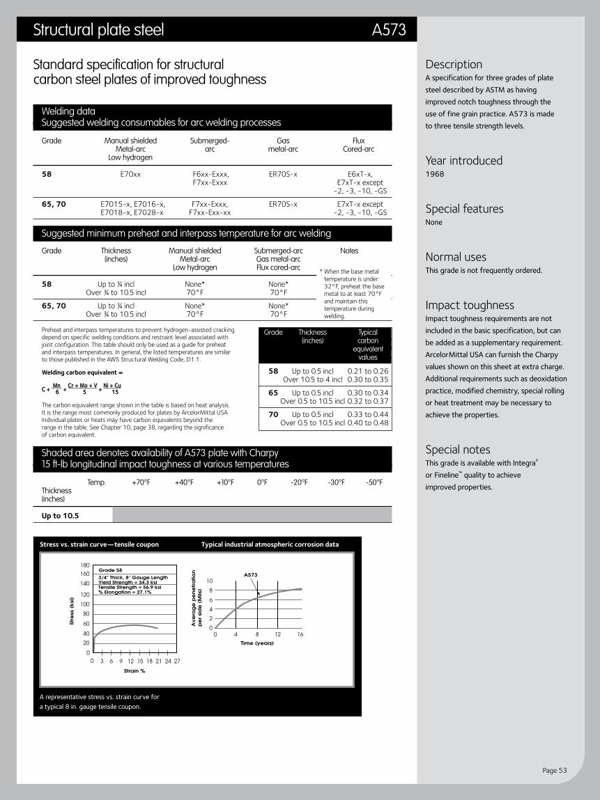
Page 53
DescriptionA specification for three grades of plate steel described by ASTM as having improved notch toughness through the use of fine grain practice. A573 is made to three tensile strength levels.
Year introduced1968
Special featuresNone
Normal usesThis grade is not frequently ordered.
Impact toughnessImpact toughness requirements are not included in the basic specification, but can be added as a supplementary requirement. ArcelorMittal USA can furnish the Charpy values shown on this sheet at extra charge. Additional requirements such as deoxidation practice, modified chemistry, special rolling or heat treatment may be necessary to achieve the properties.
Special notesThis grade is available with Integra® or Fineline™ quality to achieve improved properties.
Standard specification for structural carbon steel plates of improved toughness
Welding dataSuggested welding consumables for arc welding processes
Grade Manual shielded Submerged- Gas Flux Metal-arc arc metal-arc Cored-arc Low hydrogen
58 E70xx F6xx-Exxx, ER70S-x E6xT-x, F7xx-Exxx E7xT-x except -2, -3, -10, -GS
65, 70 E7015-x, E7016-x, F7xx-Exxx, ER70S-x E7xT-x except E7018-x, E7028-x F7xx-Exx-xx -2, -3, -10, -GS
Suggested minimum preheat and interpass temperature for arc welding
Grade Thickness Manual shielded Submerged-arc Notes (inches) Metal-arc Gas metal-arc Low hydrogen Flux cored-arc
58 Up to ¾ incl None* None* Over ¾ to 10.5 incl 70°F 70°F
65, 70 Up to ¾ incl None* None* Over ¾ to 10.5 incl 70°F 70°F
Preheat and interpass temperatures to prevent hydrogen-assisted cracking depend on specific welding conditions and restraint level associated with joint configuration. This table should only be used as a guide for preheat and interpass temperatures. In general, the listed temperatures are similar to those published in the AWS Structural Welding Code, D1.1.
Welding carbon equivalent =
C + Mn + Cr + Mo + V + Ni + Cu 6 5 15
The carbon equivalent range shown in the table is based on heat analysis. It is the range most commonly produced for plates by ArcelorMittal USA. Individual plates or heats may have carbon equivalents beyond the range in the table. See Chapter 10, page 38, regarding the significance of carbon equivalent.
Shaded area denotes availability of A573 plate with Charpy15 ft-lb longitudinal impact toughness at various temperatures
Temp. +70°F +40°F +10°F 0°F -20°F -30°F -50°F Thickness (inches)
Up to 10.5
* When the base metal temperature is under 32°F, preheat the base metal to at least 70°F and maintain this temperature during welding.
Grade Thickness Typical (inches) carbon equivalent values
58 Up to 0.5 incl 0.21 to 0.26 Over 10.5 to 4 incl 0.30 to 0.35
65 Up to 0.5 incl 0.30 to 0.34 Over 0.5 to 10.5 incl 0.32 to 0.37
70 Up to 0.5 incl 0.33 to 0.44 Over 0.5 to 10.5 incl 0.40 to 0.48
Stress vs. strain curve—tensile coupon Typical industrial atmospheric corrosion data
A representative stress vs. strain curve for a typical 8 in. gauge tensile coupon.
Structural plate steel A573

Guidelines for fabricating and processing plate steel
Page 54
Stress vs. strain curve—tensile coupon Typical industrial atmospheric corrosion data
DescriptionSpecification covers a grade of steel for plates, shapes and bars. Only data applicable to plates is shown. A588 is a high-strength, low-alloy grade produced in three strength levels. ASTM describes this grade as being approximately four times as corrosion resistant as carbon steel without copper. When required, the customer can obtain evidence of its corrosion resistance from ArcelorMittal USA. A588 can be made in Grades A through K. ArcelorMittal USA makes Grade B under the trade name Mayari- R50™. Mayari-R60™ and Cor-Ten® is modified A588 Grade B with yield and tensile strength higher than A588 specifies. This specification is approved for use by the Department of Defense.
Year introduced1968
Special featuresA high-strength, corrosion-resistant grade, the oxide of which forms a protective coating. This grade, while similar to A242, is available in greater thicknesses.
Normal usesThis corrosion-resistant steel, the oxide of which forms a protective coating, is used in many painted and unpainted applications (buildings, bridges, industrial equipment, railroad rolling stock). For bridges, this grade is specified as A709 Grade 50W.
Impact toughnessImpact toughness requirements are not included in the basic specification, but can be added as a supplementary requirement. ArcelorMittal USA can furnish the Charpy values shown on this sheet at extra charge. Additional requirements, such as deoxidation practice, modified chemistry, special rolling or heat treatment may be necessary to achieve the properties.
Special notesThis grade is available with Integra® or Fineline™ quality to achieve improved properties. Post-weld heat treatment may degrade heat-affected zone strength and toughness. Pretesting of specific welding and post-weld heat treating procedures is recommended to assure optimization of final property levels.
ASTM color codeBlue and yellow
Standard specification for high-strength, low-alloy structural steel with 50 ksi (345 mpa) minimum yield point to 4 inches (100 mm) thick (Specification allows thicknesses to 8 inches with reduced yield point.)
Welding dataSuggested welding consumables for arc welding processes
Grade Manual shielded Submerged- Gas Flux Notes Metal-arc arc metal-arc cored-arc Low hydrogen
All E7015, E7016, F7xx-Exxx ER70S-x E7xT-x except E7018, E7028, or -2, -3, -10, -GS E7015-x, F7xx-Exx-xx E7016-x, E7018-x
Suggested minimum preheat and interpass temperature for arc welding
Grade Thickness Manual shielded Submerged-arc (inches) Metal-arc Gas metal-arc Low hydrogen Flux cored-arc
A, B Up to ¾ incl 70°F 70°F Over ¾ to 10.5 incl 70°F 70°F Over 10.5 to 20.5 incl 150°F 150°F Over 20.5 to 8 incl 225°F 225°F
Preheat and interpass temperatures to prevent hydrogen-assisted cracking depend on specific welding conditions and restraint level associated with joint configuration. This table should only be used as a guide for preheat and interpass temperatures. In general, the listed temperatures are similar to those published in the AWS Structural Welding Code, D1.1.
Welding carbon equivalent =
C + Mn + Cr + Mo + V + Ni + Cu 6 5 15
The carbon equivalent range shown in the table is based on heat analysis. It is the range most commonly produced for plates by ArcelorMittal USA. Individual plates or heats may have carbon equivalents beyond the range in the table. See Chapter 10, page 38, regarding the significance of carbon equivalent.
Shaded area denotes availability of A588 grade B plate with Charpy15 ft-lb longitudinal impact toughness at various temperatures
Temp. +70°F +40°F +10°F 0°F -20°F -30°F -60°F Thickness (inches)
Up to 4 incl
Over 4 to 6 incl
Over 6
Grade Thickness Typical (inches) carbon equivalent values
A, B Up to 10.5 incl 0.28 to 0.45 Over 10.5 to 4 incl 0.33 to 0.47 Over 4 to 8 incl 0.35 to 0.50
Special welding materials and procedures, e.g. E80xx-x low alloy electrodes may be required to match the notch toughness of the base metal, or for atmospheric corrosion and weathering characteristics.
A representative stress vs. strain curve for a typical 8 in. gauge tensile coupon.
A588 Structural plate steel
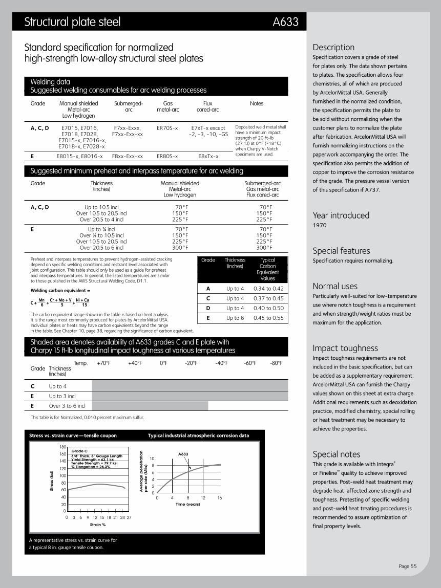
Page 55
DescriptionSpecification covers a grade of steel for plates only. The data shown pertains to plates. The specification allows four chemistries, all of which are produced by ArcelorMittal USA. Generally furnished in the normalized condition, the specification permits the plate to be sold without normalizing when the customer plans to normalize the plate after fabrication. ArcelorMittal USA will furnish normalizing instructions on the paperwork accompanying the order. The specification also permits the addition of copper to improve the corrosion resistance of the grade. The pressure vessel version of this specification if A737.
Year introduced1970
Special featuresSpecification requires normalizing.
Normal usesParticularly well-suited for low-temperature use where notch toughness is a requirement and when strength/weight ratios must be maximum for the application.
Impact toughnessImpact toughness requirements are not included in the basic specification, but can be added as a supplementary requirement. ArcelorMittal USA can furnish the Charpy values shown on this sheet at extra charge. Additional requirements such as deoxidation practice, modified chemistry, special rolling or heat treatment may be necessary to achieve the properties.
Special notesThis grade is available with Integra® or Fineline™ quality to achieve improved properties. Post-weld heat treatment may degrade heat-affected zone strength and toughness. Pretesting of specific welding and post-weld heat treating procedures is recommended to assure optimization of final property levels.
Standard specification for normalized high-strength low-alloy structural steel plates
Welding dataSuggested welding consumables for arc welding processes
Grade Manual shielded Submerged- Gas Flux Notes Metal-arc arc metal-arc cored-arc Low hydrogen
A, C, D E7015, E7016, F7xx-Exxx, ER70S-x E7xT-x except E7018, E7028, F7xx-Exx-xx -2, -3, -10, -GS E7015-x, E7016-x, E7018-x, E7028-x
E E8015-x, E8016-x F8xx-Exx-xx ER80S-x E8xTx-x
Suggested minimum preheat and interpass temperature for arc welding
Grade Thickness Manual shielded Submerged-arc (inches) Metal-arc Gas metal-arc Low hydrogen Flux cored-arc
A, C, D Up to 10.5 incl 70°F 70°F Over 10.5 to 20.5 incl 150°F 150°F Over 20.5 to 4 incl 225°F 225°F
E Up to ¾ incl 70°F 70°F Over ¾ to 10.5 incl 150°F 150°F Over 10.5 to 20.5 incl 225°F 225°F Over 20.5 to 6 incl 300°F 300°F
Preheat and interpass temperatures to prevent hydrogen-assisted cracking depend on specific welding conditions and restraint level associated with joint configuration. This table should only be used as a guide for preheat and interpass temperatures. In general, the listed temperatures are similar to those published in the AWS Structural Welding Code, D1.1.
Welding carbon equivalent =
C + Mn + Cr + Mo + V + Ni + Cu 6 5 15
The carbon equivalent range shown in the table is based on heat analysis. It is the range most commonly produced for plates by ArcelorMittal USA. Individual plates or heats may have carbon equivalents beyond the range in the table. See Chapter 10, page 38, regarding the significance of carbon equivalent.
Shaded area denotes availability of A633 grades C and E plate withCharpy 15 ft-lb longitudinal impact toughness at various temperatures
Temp. +70°F +40°F 0°F -20°F -40°F -60°F -80°F Grade Thickness (inches)
C Up to 4
E Up to 3 incl
E Over 3 to 6 incl
This table is for Normalized, 0.010 percent maximum sulfur.
Deposited weld metal shall have a minimum impact strength of 20 ft-lb (27.1J) at 0°F (-18°C) when Charpy V-Notch specimens are used.
Grade Thickness Typical (inches) Carbon Equivalent Values
A Up to 4 0.34 to 0.42
C Up to 4 0.37 to 0.45
D Up to 4 0.40 to 0.50
E Up to 6 0.45 to 0.55
Stress vs. strain curve—tensile coupon Typical industrial atmospheric corrosion data
A representative stress vs. strain curve for a typical 8 in. gauge tensile coupon.
Structural plate steel A633

Guidelines for fabricating and processing plate steel
Page 56
DescriptionSpecification covers a grade of steel for plates. Produced as killed steel with fine grain practice, it is available in four strength levels. ASTM allows two types based on composition. ArcelorMittal USA produces Type 7 by a controlled-rolling process (see Chapter 4), which results in a plate having formability, weldability and remarkable impact toughness properties.
Year introduced1972
Special featuresA high-strength, low-alloy steel grade with excellent mechanical and fabricating properties.
Normal usesDemanding structural applications where strength-to-weight ratios are maximized. Frequency used as a replacement for some quenched and tempered plate steel grades. Its formability allows replacement of multi-piece weldments with formed parts.
Impact toughnessImpact toughness requirements are not included in the basic specification, but can be added as a supplementary requirement. ArcelorMittal USA can furnish the Charpy values shown on this sheet at extra charge. Additional requirements such as deoxidation practice, modified chemistry, special rolling or heat treatment may be necessary to achieve the properties.
Special notesThis grade is available with Integra® or Fineline™ quality to achieve improved properties. Post-weld heat treatment may degrade heat-affected zone strength and toughness. Pretesting of specific welding and post-weld heat treating procedures is recommended to assure optimization of final property levels.
Standard specification for hot-rolled structural steel, high-strength, low-alloy plate with improved formability
Welding dataSuggested welding consumables for arc welding processes
Grade Manual shielded Submerged- Gas Flux Notes Metal-arc arc metal-arc cored-arc Low hydrogen
50 E7015-x, E7016-x, F7xx-Exx-xx ER70S-x E7xT-x except E7018-x, E7028-x -2, -3, -10, -GS
60 E7015-x, E7016-x, F7xx-Exx-xx ER70S-x E7xT-x except E7018-x, E7028-x -2, -3, -10, -GS
70 E8015-x, E8016-x F8xx-Exx-xx ER80S-x E8xTx-x
80 E10018-x F10x-Exx-xx ER100S-x E100T1-K3, E100T1-K5
Suggested minimum preheat and interpass temperature for arc welding
Grade Thickness Manual shielded Submerged-arc (inches) Metal-arc Gas metal-arc Low hydrogen Flux cored-arc
50 Up to 20.5 70°F 70°F
60 Up to 1.25 70°F 70°F
70 Up to 1 70°F 70°F
80 Up to ¾ 70°F 70°F
Preheat and interpass temperatures to prevent hydrogen-assisted cracking depend on specific welding conditions and restraint level associated with joint configuration. This table should only be used as a guide for preheat and interpass temperatures. In general, the listed temperatures are similar to those published in the AWS Structural Welding Code, D1.1.
Welding carbon equivalent =
C + Mn + Cr + Mo + V + Ni + Cu 6 5 15
The carbon equivalent range shown in the table is based on heat analysis. It is the range most commonly produced for plates by ArcelorMittal USA. Individual plates or heats may have carbon equivalents beyond the range in the table. See Chapter 10, page 38, regarding the significance of carbon equivalent.
Shaded area denotes availability of A656 grade 80 plate withCharpy 15 ft-lb longitudinal impact toughness at various temperatures
Temp. +70°F +40°F +10°F 0°F -20°F -30°F -50°F Thickness (inches)
Up to ¾
If impact properties are required, other electrode/flux combinations, as designated in AWS, can be specified; for example, F7A4-Exx-xx specifies 20 ft-lb at -60°F.
Grade Thickness Typical (inches) carbon equivalent values
50 Up to 20.5 0.27 to 0.31
60 Up to 1.25 0.28 to 0.32
70 Up to 1 0.30 to 0.34
80 Up to ¾ 0.37 to 0.41
Typical industrial atmospheric corrosion data
A656 Structural plate steel
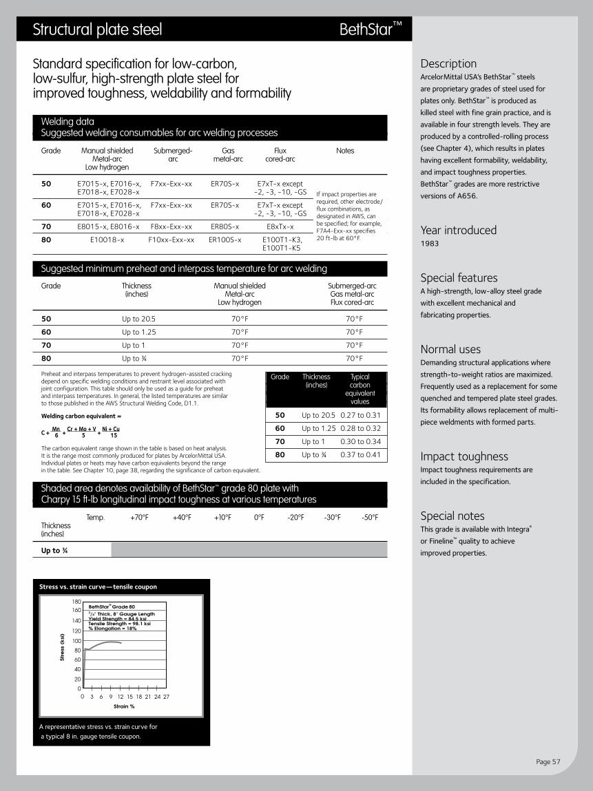
Page 57
DescriptionArcelorMittal USA’s BethStar™ steels are proprietary grades of steel used for plates only. BethStar™ is produced as killed steel with fine grain practice, and is available in four strength levels. They are produced by a controlled-rolling process (see Chapter 4), which results in plates having excellent formability, weldability, and impact toughness properties. BethStar™ grades are more restrictive versions of A656.
Year introduced1983
Special featuresA high-strength, low-alloy steel grade with excellent mechanical and fabricating properties.
Normal usesDemanding structural applications where strength-to-weight ratios are maximized. Frequently used as a replacement for some quenched and tempered plate steel grades. Its formability allows replacement of multi-piece weldments with formed parts.
Impact toughnessImpact toughness requirements are included in the specification.
Special notesThis grade is available with Integra® or Fineline™ quality to achieve improved properties.
Standard specification for low-carbon, low-sulfur, high-strength plate steel for improved toughness, weldability and formability
Welding dataSuggested welding consumables for arc welding processes
Grade Manual shielded Submerged- Gas Flux Notes Metal-arc arc metal-arc cored-arc Low hydrogen
50 E7015-x, E7016-x, F7xx-Exx-xx ER70S-x E7xT-x except E7018-x, E7028-x -2, -3, -10, -GS
60 E7015-x, E7016-x, F7xx-Exx-xx ER70S-x E7xT-x except E7018-x, E7028-x -2, -3, -10, -GS
70 E8015-x, E8016-x F8xx-Exx-xx ER80S-x E8xTx-x
80 E10018-x F10xx-Exx-xx ER100S-x E100T1-K3, E100T1-K5
Suggested minimum preheat and interpass temperature for arc welding
Grade Thickness Manual shielded Submerged-arc (inches) Metal-arc Gas metal-arc Low hydrogen Flux cored-arc
50 Up to 20.5 70°F 70°F
60 Up to 1.25 70°F 70°F
70 Up to 1 70°F 70°F
80 Up to ¾ 70°F 70°F
Preheat and interpass temperatures to prevent hydrogen-assisted cracking depend on specific welding conditions and restraint level associated with joint configuration. This table should only be used as a guide for preheat and interpass temperatures. In general, the listed temperatures are similar to those published in the AWS Structural Welding Code, D1.1.
Welding carbon equivalent =
C + Mn + Cr + Mo + V + Ni + Cu 6 5 15
The carbon equivalent range shown in the table is based on heat analysis. It is the range most commonly produced for plates by ArcelorMittal USA. Individual plates or heats may have carbon equivalents beyond the range in the table. See Chapter 10, page 38, regarding the significance of carbon equivalent.
Shaded area denotes availability of BethStar™ grade 80 plate withCharpy 15 ft-lb longitudinal impact toughness at various temperatures
Temp. +70°F +40°F +10°F 0°F -20°F -30°F -50°F Thickness (inches)
Up to ¾
If impact properties are required, other electrode/flux combinations, as designated in AWS, can be specified; for example, F7A4-Exx-xx specifies 20 ft-lb at 60°F.
Grade Thickness Typical (inches) carbon equivalent values
50 Up to 20.5 0.27 to 0.31
60 Up to 1.25 0.28 to 0.32
70 Up to 1 0.30 to 0.34
80 Up to ¾ 0.37 to 0.41
Stress vs. strain curve—tensile coupon
A representative stress vs. strain curve for a typical 8 in. gauge tensile coupon.
Structural plate steel BethStar™

Guidelines for fabricating and processing plate steel
Page 58
Stress vs. strain curve—tensile coupon Typical industrial atmospheric corrosion data
DescriptionSpecification covers a carbon grade for plates made to a fine grain practice. The specification allows three compositions of which ArcelorMittal USA produces all three. The plate is heat treated by quenching and tempering to develop the high strength levels. The specification permits the addition of copper to improve the corrosion resistance of the plate.
Year introduced1973
Special featuresA high-strength steel with notch toughness.
Normal usesDemanding structural, industrial and machinery applications where weight reduction is important and notch toughness is a design consideration.
Impact toughnessImpact toughness requirements are not included in the basic specification, but can be added as a supplementary requirement. ArcelorMittal USA can furnish the Charpy values shown on this sheet at extra charge. Additional requirements such as deoxidation practice, modified chemistry, special rolling or heat treatment may be necessary to achieve the properties.
Special notesThis grade is available with Integra® or Fineline™ quality to achieve improved properties.
Standard specification for quenched and tempered carbon steel and high-strength, low-alloy structural steel plates
Welding dataSuggested welding consumables for arc welding processes
Grade Manual shielded Submerged- Gas Flux Metal-arc arc metal-arc cored-Arc Low hydrogen
A E7015-x, E7016-x, F7xx-Exx-xx ER70S-x E7xT-x except E7018-x, E7028-x -2, -3, -10, -GSB E8015-x, E8016-x, F8xx-Exx-xx ER80S-x E8xTx-x E8018-xC, D E9015-x, E9016-x, F9xx-Exx-xx ER90S-x E9xTx-x E9018-x
Suggested minimum preheat and interpass temperature for arc welding
Grade Thickness Manual shielded Submerged-arc (inches) Metal-arc Gas metal-arc Low hydrogen Flux cored-arc
A Up to ¾ incl 70°F 70°F Over ¾ to 10.5 incl 100°F 100°FB, C Up to ¾ incl 100°F 100°F Over ¾ to 10.5 incl 150°F 150°F Over 10.5 to 2 incl 225°F 225°FD Up to ¾ incl 100°F 100°F Over ¾ to 10.5 incl 175°F 175°F Over 10.5 to 3 incl 250°F 250°F
Preheat and interpass temperatures to prevent hydrogen-assisted cracking depend on specific welding conditions and restraint level associated with joint configuration. This table should only be used as a guide for preheat and interpass temperatures. In general, the listed temperatures are similar to those published in the AWS Structural Welding Code, D1.1.
Welding carbon equivalent =
C + Mn + Cr + Mo + V + Ni + Cu 6 5 15
The carbon equivalent range shown in the table is based on heat analysis. It is the range most commonly produced for plates by ArcelorMittal USA. Individual plates or heats may have carbon equivalents beyond the range in the table. See Chapter 10, page 38, regarding the significance of carbon equivalent.
Shaded area denotes availability of A678 grade B plate with Charpy15 ft-lb longitudinal impact toughness at various temperatures
Temp. +70°F +40°F +10°F 0°F -20°F -30°F -50°F Thickness (inches)
Up to 20.5
Grade Thickness Typical (inches) carbon equivalent values
A Up to 10.5 0.31 to 0.35
B Up to 20.5 0.32 to 0.37
C Up to 2 0.39 to 0.45
D Up to 3 0.39 to 0.47
A representative stress vs. strain curve for a typical 8 in. gauge tensile coupon.
A678 Structural plate steel

Page 59
DescriptionA high-strength alloy plate specification that provides outstanding formability, weldability and toughness, it has excellent CVN toughness and is readily weldable, requiring no preheat for many applications. It is particularly well-suited for critical applications such as Navy surface vessel hull plates and fracture-critical components on offshore drill rigs. The pressure vessel version of this specification is A736.
Year introduced1974
Special featuresThis precipitation hardened grade has an excellent combination of strength, toughness and weldability. Other chemistries for higher stre ngth levels are also available under the ArcelorMittal USA trade name Spartan.™
Normal usesNaval surface vessel hull plates. May be ordered to military specification Mil-S-24645 (SH), which requires high strength and impact properties, for approved use in critical structural applications.
Impact toughnessThe test results for Class 1 shall meet an average minimum value of 20 ft-lb at -50°F for longitudinal specimens. For transverse specimens, the test results shall meet an average minimum value of 15 ft-lb at -50°F. Impact toughness guarantees are available for both classes at test temperatures down to -120°F. Additional requirements such as deoxidation practice, modified chemistry, special rolling or heat treatment may be necessary to achieve the properties.
Special notesThis grade is produced with Fineline™ quality to achieve improved properties. It is important to note this grade of steel may be susceptible to cracking in the heat-affected zone of welds during post-weld heat treatment (stress relief) or elevated temperature service. Also, post-weld heat treatment of elevated temperature service may degrade heat affected zone toughness. Therefore, ArcelorMittal USA recommends careful consideration be given to these phenomena by competent welding engineers before application.
Standard specification for age-hardening low-carbon nickel-copper-chromium-molybdenum-columbium alloy structural steel plates
Welding dataSuggested welding consumables for arc welding processes
Grade Thickness Manual shielded Submerged- Gas Flux Notes Class (inches) Metal-arc arc metal-arc cored-arc Low hydrogen
A E10015-x, F10xx-Exx-xx ER100S-x E10xTx-x Class 1 Up to ¾ E10016-x, Class 3 Up to 2 incl E10018-x
A E8015-x, F8xx-Exx-xx ER80S-x E8xTx-x Class 3 Over 2 E8016-x, E8018-x
Suggested minimum preheat and interpass temperature for arc welding
Grade Thickness Manual shielded Submerged-arc Notes (inches) Metal-arc Gas metal-arc Low hydrogen Flux cored-arc
A Up to 4 incl None None Class 1, 3 Over 4 to 8 incl 50°F 50°F
Preheat and interpass temperatures to prevent hydrogen-assisted cracking depend on specific welding conditions and restraint level associated with joint configuration. This table should only be used as a guide for preheat and interpass temperatures. In general, the listed temperatures are similar to those published in the AWS Structural Welding Code, D1.1.
Welding carbon equivalent =
C + Mn + Cr + Mo + V + Ni + Cu 6 5 15
The carbon equivalent range shown in the table is based on heat analysis. It is the range most commonly produced for plates by ArcelorMittal USA. Individual plates or heats may have carbon equivalents beyond the range in the table. See Chapter 10, page 38, regarding the significance of carbon equivalent.
Class Thickness Typical (inches) carbon equivalent values
1, 3 Up to 8 0.42 to 0.48
See Special notes section for concerns about post-weld heat treatment.
Choice of welding consumable may dictate preheat requirements.
Structural plate steel A710

Guidelines for fabricating and processing plate steel
Page 60
Standard specification for high-strength, low-alloy carbon, manganese, columbium, vanadium steel of structural quality with improved notch toughness
Welding dataSuggested welding consumables for arc welding processes
Thickness Manual shielded Submerged- Gas Flux (inches) Metal-arc arc metal-arc cored-Arc Low hydrogen
Up to 20.5 E7015, E7016, F7xx-Exx-xx ER70S-x E7xT-x except E7018, E7028, -2, -3, -10, -GS E7015-x, E7016-x, E7018-x, E7028-x
Suggested minimum preheat and interpass temperature for arc welding
Thickness Manual shielded Submerged-arc Notes (inches) Metal-arc Gas metal-arc Low hydrogen Flux cored-arc
Up to ¾ incl None* None*
Over ¾ to 10.5 incl 70°F 70°F
Over 10.5 to 20.5 incl 150°F 150°F
Preheat and interpass temperatures to prevent hydrogen-assisted cracking depend on specific welding conditions and restraint level associated with joint configuration. This table should only be used as a guide for preheat and interpass temperatures. In general, the listed temperatures are similar to those published in the AWS Structural Welding Code, D1.1.
Welding carbon equivalent =
C + Mn + Cr + Mo + V + Ni + Cu 6 5 15
The carbon equivalent range shown in the table is based on heat analysis. It is the range most commonly produced for plates by ArcelorMittal USA. Individual plates or heats may have carbon equivalents beyond the range in the table. See Chapter 10, page 38, regarding the significance of carbon equivalent.
Available longitudinal Charpy toughness levels for A808 plate
Type Temperature Avg. absorb energy (ft-lb)
Restricted sulfur (0.010% max.) -20°F 55 -50°F 45
Regular sulfur -20°F 40 -50°F 30
* When the base metal temperature is under 32°F, preheat the base metal to at least 70°F and maintain this temperature during welding.
Grade Thickness Typical (inches) carbon equivalent values
All Up to 20.5 0.30 to 0.44
Stress vs. strain curve—tensile coupon Typical industrial atmospheric corrosion data
DescriptionSpecification covers a grade of steel plates. A808, a high-strength, low-alloy grade of steel is made to fine grain practice. The plate may be made by controlled-finishing temperature rolling practice. The specification identifies two levels of sulfur content. The supplemental specification lists the Charpy impact values available.
Year introduced1982
Special featuresA grade which may be substituted for more expensive normalized grades (A633) in certain applications.
Normal usesUses are in applications where notch toughness is an important design consideration.
Impact toughnessImpact toughness requirements are not included in the basic specification, but can be added as a supplementary requirement. ArcelorMittal USA can furnish the Charpy values shown on this sheet at extra charge. Additional requirements such as deoxidation practice, modified chemistry, special rolling or heat treatment may be necessary to achieve the properties.
Special notesThis grade is available with Integra® or Fineline™ quality to achieve improved properties. Post-weld heat treatment may degrade heat-affected zone strength and toughness. Pretesting of specific welding and post-weld heat treating procedures is recommended to assure optimization of final property levels.
A representative stress vs. strain curve for a typical 8 in. gauge tensile coupon.
A808 Structural plate steel

Page 61
DescriptionSpecification covers a grade of steel for plates. Only data applicable to plates is shown. A871 is a high-strength, low-alloy grade produced in two strength levels. ASTM describes this grade as being approximately four times as corrosion resistant as carbon steel without copper. When required, the customer can obtain evidence of its corrosion resistance from ArcelorMittal USA. A871 can be made in Grades 60 and 65.
Year introduced1987
Special featuresA high-strength, corrosion-resistant grade whose oxide forms a protective coating similar to A588.
Normal usesThis corrosion-resistant steel, whose oxide forms a protective coating, is used in many painted and unpainted applications.
Impact toughnessImpact toughness requirements are included in the basic specification. To 0.5 inch 15 ft-lb at 0°F, over 0.5 inch 15 ft-lb at -20°F. Other requirements need to be inquired. Additional requirements such as deoxidation practice, modified chemistry, special rolling or heat treatment may be necessary to achieve the properties.
Special notesThis grade is available with Integra® or Fineline™ quality to achieve improved properties. Post-weld heat treatment may degrade heat-affected zone strength and toughness. Pretesting of specific welding and post-weld heat treating procedures is recommended to assure optimization of final property levels.
Structural plate steel A871
Standard specification for high-strength, low-alloy structural steel with atmospheric corrosion resistanceThis specification permits varied chemistries called Types 1, 2, 3 and 4. (ArcelorMittal USA makes only Types 1 and 2.)
Welding dataSuggested welding consumables for arc welding processes
Grade Manual shielded Submerged- Gas Flux Notes Metal-arc arc metal-arc cored-arc Low hydrogen
60 E8018-W, F7Ax-Exxx-W, See E80T1-W unpainted E8016-B1, F7xx-Exxx-W AWS D1.1 after E8018-B1 fabrication
60 E7015, F7xx-Exxx ER70S-x E7xT-x except painted E7016, -2, -3, -10, -GS after E7018, fabrication E7028
65 E8018-W, F8xx-Exx-W See E80T1-W unpainted E8016-B1, AWS D1.1 after E8018-B1 fabrication
65 E8015, F8xx-Exx-xx ER80S-x E8xTx-x painted E8016, after E8018 fabrication
Suggested minimum preheat and interpass temperature for arc welding
Grade Thickness Manual shielded Submerged-arc (inches) Metal-arc Gas metal-arc Low hydrogen Flux cored-arc
60 Up to ¾ incl 70°F 70°F Over ¾ to 10.5 incl 70°F 70°F Over 10.5 to 20.5 incl 150°F 150°F Over 20.5 to 8 incl 225°F 225°F
65 Up to ¾ incl 70°F 70°F Over ¾ to 10.5 incl 150°F 150°F Over 10.5 to 20.5 incl 225°F 225°F Over 20.5 to 4 incl 300°F 300°F
Preheat and interpass temperatures to prevent hydrogen-assisted cracking depend on specific welding conditions and restraint level associated with joint configuration. This table should only be used as a guide for preheat and interpass temperatures. In general, the listed temperatures are similar to those published in the AWS Structural Welding Code, D1.1.
Welding carbon equivalent =
C + Mn + Cr + Mo + V + Ni + Cu 6 5 15
The carbon equivalent range shown in the table is based on heat analysis. It is the range most commonly produced for plates by ArcelorMittal USA. Individual plates or heats may have carbon equivalents beyond the range in the table. See Chapter 10, page 38, regarding the significance of carbon equivalent.
Shaded area denotes availability of A871 grade 60 plate withCharpy 15 ft-lb longitudinal impact toughness at various temperatures
Temp. +70°F +40°F +10°F 0°F -20°F -30°F -60°F Thickness (inches)
Up to 4 incl
Over 4 to 6 incl
E7015, -16, -18 or -28 can be used for unpainted structure in single-pass fillet welds to 0.25 inch maximum and in single-pass groove welds of 0.25 inch maximum since these welds have high base metal dilution.
Grade Thickness Typical (inches) carbon equivalent values
60 Up to 20.5 incl 0.42 to 0.53
60 Over 20.5 to 6 incl 0.47 to 0.57
65 Up to 10.5 incl 0.42 to 0.53
65 Over 10.5 to 4 incl 0.47 to 0.53
t i n u e dc o n

Guidelines for fabricating and processing plate steel
Page 62
Standard specification for high-strength, low-alloy structural steel with atmospheric corrosion resistance
Stress vs. strain curve—tensile coupon Typical industrial atmospheric corrosion data
A representative stress vs. strain curve for a typical 8 in. gauge tensile coupon.
t i n u e dc o n
A871 Structural plate steel

Page 63
Structural plate steel Hardwear®
DescriptionArcelorMittal USA Hardwear® steels are proprietary grades produced by quenching and tempering to achieve two nominal Brinell hardness levels, 400HB and 500HB.
Year introduced1989
Special featuresHigh hardness for abrasive resistance with low sulfur levels for improved weldability and formability.
Normal usesAbrasive resistant applications in mining, quarries and earth-moving.
Impact toughnessImpact requirements may be furnished at an extra charge.
Special notesThis grade is always produced as Fineline™. Both tables must be consulted and the higher preheat value used. Preheat temperature based on shielded metal-arc welding (SMAW) process and E7018 electrode. E7018 electrodes must be stored in an oven at 250°F ± 25°F. Maximum exposure—four hours out of the can or out of the oven. Preheat minimum temperature may be reduced by 50°F (but not less than 50°F) using gas metal-arc welding process, ER70S-3 electrode and Ar-CO2 gas. Maximum preheat should be 400°F to retain hardness properties. 35 KJ/inch represents approximately a 0.25 inch fillet weld (SMAW).
Standard specification for premium abrasion-resistant plate steel available in two grades, Hardwear
® 400F and Hardwear
® 500F
Welding dataSuggested welding consumables for arc welding processes
Thickness Manual shielded Submerged- Gas Flux Metal-arc arc metal-arc cored-arc Low hydrogen
All E7015, E7016, E7xx-Exxx ER70S-x E7xT-x except E7018, E7028, or -2, -3, -10, -GS E7015-x, E7016-x, E7xx-Exxx-xx E7018-x
Suggested minimum preheat and interpass temperature (°F) See special notes
Hardwear® 400F Hardwear® 500F heat input (KJ/Inch) heat input (KJ/Inch)
Individual Plate Thickness (inches) 30 35 40 45 Over 45 30 35 40 45
0.5 60 60 60 60 60 200 200 200 2005⁄8 60 60 60 60 60 250 200 200 200
¾ 60 60 60 60 60 300 250 200 200
1 60 60 60 60 60 350 300 250 200
1.25 60 60 60 60 60 400 300 250 200
10.5 60 60 60 60 60 400 350 300 250
2 200 200 200 200 200 400 400 350 300
Suggested minimum preheat and interpass temperature (°F) See Special notes
Hardwear® 400F Hardwear® 500F heat input (KJ/Inch) heat input (KJ/Inch)
Combined plate thickness (inches) t1 + t2 + t3 30 35 40 45 Over 45 30 35 40 45
¾ 60 60 60 60 60 200 200 200 200
1 60 60 60 60 60 250 200 200 200
1.25 60 60 60 60 60 300 250 200 200
10.5 60 60 60 60 60 350 300 250 200
2 60 60 60 60 60 400 350 300 300
20.5 60 60 60 60 60 400 350 300 250
3 200 200 200 60 60 400 400 350 350
4 250 250 250 200 200 400 400 400 400
Preheat and interpass temperatures to prevent hydrogen-assisted cracking depend on specific welding conditions and restraint level associated with joint configuration. This table should only be used as a guide for preheat and interpass temperatures. In general, the listed temperatures are similar to those published in the AWS Structural Welding Code, D1.1.
Welding carbon equivalent =
C + Mn + Cr + Mo + V + Ni + Cu 6 5 15
The carbon equivalent range shown in the table is based on heat analysis. It is the range most commonly produced for plates by ArcelorMittal USA. Individual plates or heats may have carbon equivalents beyond the range in the table. See Chapter 10, page 38, regarding the significance of carbon equivalent.
Grade Thickness Typical (inches) C.E. values
400F Up to 3 0.44 to 0.51
500F Up to 3 0.53 to 0.58
t1
L
L
t1
t1
t3t2
t3t3 t2t2
L
If L is less than or equal to 0.5 t2, consider t2 = 0.

Guidelines for fabricating and processing plate steel
Page 64
Welding and other data on pressure vessel plate steel grades
Structural grades
Grade Page number Grade Page number
A204 65 A517 74
A285 66 A533 75
A299 67 A537 76-77
A302 68 A612 78
A387 69 A662 79
A455 70 A737 80
A515 71 A738 81
A516 72–73 A841 82
Pressure vessel plate steelChapter 12
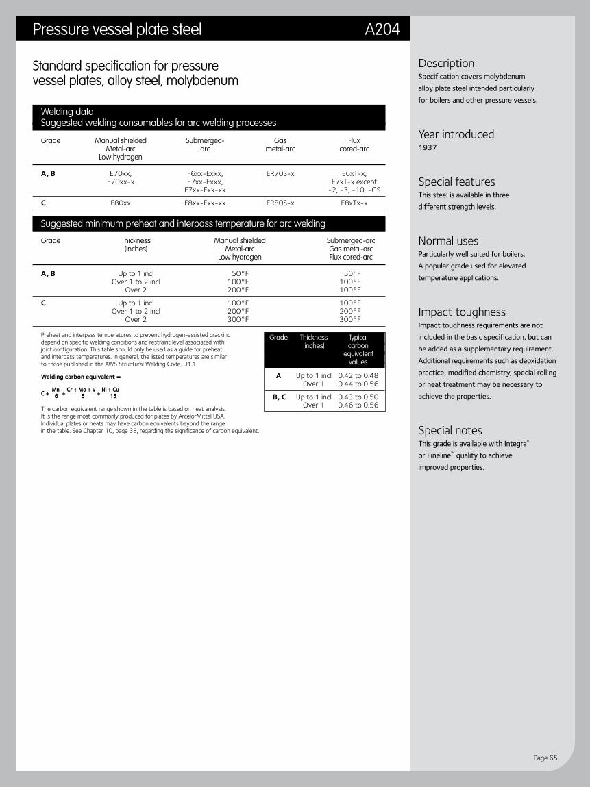
Page 65
Pressure vessel plate steel A204
DescriptionSpecification covers molybdenum alloy plate steel intended particularly for boilers and other pressure vessels.
Year introduced1937
Special featuresThis steel is available in three different strength levels.
Normal usesParticularly well suited for boilers. A popular grade used for elevated temperature applications.
Impact toughnessImpact toughness requirements are not included in the basic specification, but can be added as a supplementary requirement. Additional requirements such as deoxidation practice, modified chemistry, special rolling or heat treatment may be necessary to achieve the properties.
Special notesThis grade is available with Integra® or Fineline™ quality to achieve improved properties.
Standard specification for pressure vessel plates, alloy steel, molybdenum
Welding dataSuggested welding consumables for arc welding processes
Grade Manual shielded Submerged- Gas Flux Metal-arc arc metal-arc cored-arc Low hydrogen
A, B E70xx, F6xx-Exxx, ER70S-x E6xT-x, E70xx-x F7xx-Exxx, E7xT-x except F7xx-Exx-xx -2, -3, -10, -GS
C E80xx F8xx-Exx-xx ER80S-x E8xTx-x
Suggested minimum preheat and interpass temperature for arc welding
Grade Thickness Manual shielded Submerged-arc (inches) Metal-arc Gas metal-arc Low hydrogen Flux cored-arc
A, B Up to 1 incl 50°F 50°F Over 1 to 2 incl 100°F 100°F Over 2 200°F 100°F
C Up to 1 incl 100°F 100°F Over 1 to 2 incl 200°F 200°F Over 2 300°F 300°F
Preheat and interpass temperatures to prevent hydrogen-assisted cracking depend on specific welding conditions and restraint level associated with joint configuration. This table should only be used as a guide for preheat and interpass temperatures. In general, the listed temperatures are similar to those published in the AWS Structural Welding Code, D1.1.
Welding carbon equivalent =
C + Mn + Cr + Mo + V + Ni + Cu 6 5 15
The carbon equivalent range shown in the table is based on heat analysis. It is the range most commonly produced for plates by ArcelorMittal USA. Individual plates or heats may have carbon equivalents beyond the range in the table. See Chapter 10, page 38, regarding the significance of carbon equivalent.
Grade Thickness Typical (inches) carbon equivalent values
A Up to 1 incl 0.42 to 0.48 Over 1 0.44 to 0.56
B, C Up to 1 incl 0.43 to 0.50 Over 1 0.46 to 0.56

Guidelines for fabricating and processing plate steel
Page 66
Standard specification for pressure vessel plates, carbon steel, low and intermediate tensile strength
Welding dataSuggested welding consumables for arc welding processes
Grade Manual shielded Submerged- Gas Flux Metal-arc arc metal-arc cored-arc Low hydrogen
A, B, C E60xx, E70xx, F6xx-Exxx, ER70S-x E6xT-x, E70xx-x F7xx-Exxx, E7xT-x except F7xx-Exx-xx -2, -3, -10, -GS
Suggested minimum preheat and interpass temperature for arc welding
Grade Thickness Manual shielded Submerged-arc Notes (inches) Metal-arc Gas metal-arc Low hydrogen Flux cored-arc
A, B, C Up to ¾ incl None* None* Over ¾ to 10.5 incl 50°F 50°F Over 10.5 150°F 150°F
Preheat and interpass temperatures to prevent hydrogen-assisted cracking depend on specific welding conditions and restraint level associated with joint configuration. This table should only be used as a guide for preheat and interpass temperatures. In general, the listed temperatures are similar to those published in the AWS Structural Welding Code, D1.1.
Welding carbon equivalent =
C + Mn + Cr + Mo + V + Ni + Cu 6 5 15
The carbon equivalent range shown in the table is based on heat analysis. It is the range most commonly produced for plates by ArcelorMittal USA. Individual plates or heats may have carbon equivalents beyond the range in the table. See Chapter 10, page 38, regarding the significance of carbon equivalent.
Charpy V-Notch test minimum available requirements per ASTM A20,Table A1.15, using Type “A” (full size specimens). Longitudinal test coupon.
Impact values (ft-lb)
Grade Thickness Lowest test Avg. 3 specimens Minimum for (inches) temp. °F one specimen
A Up to 1 incl +40 10 7 Over 1 to 2 incl +60 10 7
B Up to 1 incl +50 10 7 Over 1 to 2 incl +70 10 7
C Up to 1 incl +60 10 7 Over 1 to 2 incl +80 10 7
* When the base metal temperature is under 32°F, preheat the base metal to at least 70°F and maintain this temperature during welding.
Grade Thickness Typical (inches) carbon equivalent values
A, B, Up to 10.5 incl 0.14 to 0.37 C Over 10.5 to 20.5 incl 0.14 to 0.39 Over 20.5 to 15 incl 0.14 to 0.42
Stress vs. strain curve—tensile coupon
A285 Pressure vessel plate steel
DescriptionSpecification covers carbon plate steel of low and intermediate tensile strengths. These plates are intended for fusion welded pressure vessels. This specification has been approved by the Department of Defense for listing in the DOD Index of Specifications and Standards.
Year introduced1946
Special featuresThis grade is available in three different strength levels.
Normal usesA widely used, low-cost pressure vessel grade.
Impact toughnessImpact toughness requirements are not included in the basic specification, but can be added as a supplementary requirement. ArcelorMittal USA can furnish the Charpy values shown on this sheet at extra charge. Additional requirements such as deoxidation practice, modified chemistry, special rolling or heat treatment may be necessary to achieve the properties.
Special notesPlates are normally supplied in the as-rolled condition. This steel may be made by killed, or semi-killed, steel practices. This grade is available with Integra® or Fineline™ quality to achieve improved properties.
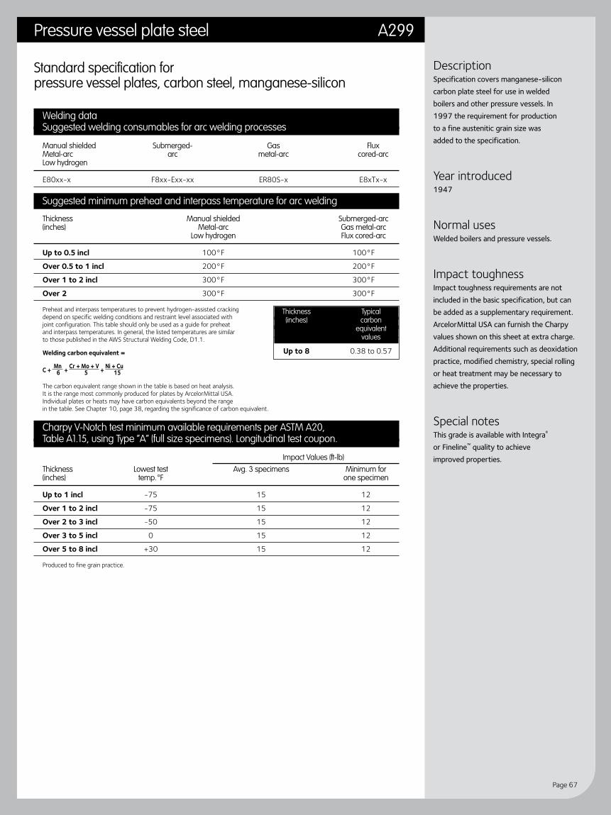
Page 67
Pressure vessel plate steel A299
DescriptionSpecification covers manganese-silicon carbon plate steel for use in welded boilers and other pressure vessels. In 1997 the requirement for production to a fine austenitic grain size was added to the specification.
Year introduced1947
Normal usesWelded boilers and pressure vessels.
Impact toughnessImpact toughness requirements are not included in the basic specification, but can be added as a supplementary requirement. ArcelorMittal USA can furnish the Charpy values shown on this sheet at extra charge. Additional requirements such as deoxidation practice, modified chemistry, special rolling or heat treatment may be necessary to achieve the properties.
Special notesThis grade is available with Integra® or Fineline™ quality to achieve improved properties.
Standard specification for pressure vessel plates, carbon steel, manganese-silicon
Welding dataSuggested welding consumables for arc welding processes
Manual shielded Submerged- Gas Flux Metal-arc arc metal-arc cored-arc Low hydrogen
E80xx-x F8xx-Exx-xx ER80S-x E8xTx-x
Suggested minimum preheat and interpass temperature for arc welding
Thickness Manual shielded Submerged-arc (inches) Metal-arc Gas metal-arc Low hydrogen Flux cored-arc
Up to 0.5 incl 100°F 100°F
Over 0.5 to 1 incl 200°F 200°F
Over 1 to 2 incl 300°F 300°F
Over 2 300°F 300°F
Preheat and interpass temperatures to prevent hydrogen-assisted cracking depend on specific welding conditions and restraint level associated with joint configuration. This table should only be used as a guide for preheat and interpass temperatures. In general, the listed temperatures are similar to those published in the AWS Structural Welding Code, D1.1.
Welding carbon equivalent =
C + Mn + Cr + Mo + V + Ni + Cu 6 5 15
The carbon equivalent range shown in the table is based on heat analysis. It is the range most commonly produced for plates by ArcelorMittal USA. Individual plates or heats may have carbon equivalents beyond the range in the table. See Chapter 10, page 38, regarding the significance of carbon equivalent.
Charpy V-Notch test minimum available requirements per ASTM A20,Table A1.15, using Type “A” (full size specimens). Longitudinal test coupon.
Impact Values (ft-lb)
Thickness Lowest test Avg. 3 specimens Minimum for (inches) temp. °F one specimen
Up to 1 incl -75 15 12
Over 1 to 2 incl -75 15 12
Over 2 to 3 incl -50 15 12
Over 3 to 5 incl 0 15 12
Over 5 to 8 incl +30 15 12
Produced to fine grain practice.
Thickness Typical (inches) carbon equivalent values
Up to 8 0.38 to 0.57

Guidelines for fabricating and processing plate steel
Page 68
Standard specification for pressure vessel plates, alloy steel, manganese-molybdenum and manganese-molybdenum-nickel
Welding dataSuggested welding consumables for arc welding processes
Grade Manual shielded Submerged- Gas Flux Metal-arc arc metal-arc cored-arc Low hydrogen
A, B, C, D E80xx-x F8xx-Exx-xx ER80S-x E8xTx-x
Suggested minimum preheat and interpass temperature for arc welding
Grade Thickness Manual shielded Submerged-arc (inches) Metal-arc Gas metal-arc Low hydrogen Flux cored-arc
A, B, C, D Up to 0.5 incl 50°F 50°F Over 0.5 to 1 incl 200°F 200°F Over 1 to 2 incl 300°F 300°F Over 2 350°F 350°F
Preheat and interpass temperatures to prevent hydrogen-assisted cracking depend on specific welding conditions and restraint level associated with joint configuration. This table should only be used as a guide for preheat and interpass temperatures. In general, the listed temperatures are similar to those published in the AWS Structural Welding Code, D1.1.
Welding carbon equivalent =
C + Mn + Cr + Mo + V + Ni + Cu 6 5 15
The carbon equivalent range shown in the table is based on heat analysis. It is the range most commonly produced for plates by ArcelorMittal USA. Individual plates or heats may have carbon equivalents beyond the range in the table. See Chapter 10, page 38, regarding the significance of carbon equivalent.
Grade Thickness Typical (inches) carbon equivalent values
A, B, Up to 2 incl 0.45 to 0.68 C, D Over 2 0.45 to 0.68
A302 Pressure vessel plate steel
DescriptionSpecifications cover manganese-molybdenum-nickel alloy plates intended particularly for welded boilers and other pressure vessels. This specification has been approved by the Department of Defense to replace Specification QQ-S-691C and for listing in the DOD Index of Specifications and Standards.
Year introduced1947
Special featuresThis steel is available in four grades having different strength levels.
Normal usesWelded boilers and pressure vessels.
Impact toughnessImpact toughness requirements are not included in the basic specification, but can be added as a supplementary requirement. Additional requirements such as deoxidation practice, modified chemistry, special rolling or heat treatment may be necessary to achieve the properties.
Special notesThis grade is available with Integra® or Fineline™ quality to achieve improved properties.

Page 69
Pressure vessel plate steel A387
DescriptionSpecification covers chromium-molybdenum, alloy plates which are annealed, normalized and tempered or quenched and tempered depending on grade. The plates are intended primarily for welded boilers and pressure vessel designs for elevated temperature and hydrogen service.
Year introduced1955
Special featuresProduced as numerous grades and classes with increasing levels of chromium and molybdenum. Grades 9 and 91 are also available.
Normal usesRecommended for welded pressure vessels.
Impact toughnessImpact toughness requirements are not included in the basic specification, but can be added as a supplementary requirement. Additional requirements such as deoxidation practice, modified chemistry, special rolling or heat treatment may be necessary to achieve the properties. The impact toughness of this specification is strongly influenced by chemistry, heat treatment and required post-weld heat treatment (PWHT). Contact ArcelorMittal USA with your specific requirements.
Special notesThis grade is available with Fineline™ quality to achieve improved properties.
Standard specification for pressure vessel plates, alloy steel, chromium-molybdenum
Welding dataSuggested welding consumables for arc welding processes
Grade Manual shielded Submerged- Gas Flux Metal-arc arc metal-arc cored-arc Low hydrogen
2, 12, 11 E8018-B2 F8xx-Exx-xx ER80S-x E8xTx-x
22 E9018-B3 F9xx-Exx-xx ER90S-x E9xTx-x
5 E502-15 # # #
# Refer to ArcelorMittal USA.
Suggested minimum preheat and interpass temperature for arc welding
Thickness (inches)
Grade Up to ¾ incl Over ¾
2, 11, 12, 22 200°F 300°F to 600°F
5 300°F 400°F to 700°F
Suggested post-weld heat treatment (PWHT) for arc welding
Grade All Thicknesses Notes
2, 12 1200°F to 1300°F for 1 hr/in
11, 22 1275°F to 1350°F for 1 hr/in
5 1300°F to 1375°F for 1 hr/in
Preheat and interpass temperatures to prevent hydrogen-assisted cracking depend on specific welding conditions and restraint level associated with joint configuration. This table should only be used as a guide for preheat and interpass temperatures. In general, the listed temperatures are similar to those published in the AWS Structural Welding Code, D1.1.
Welding carbon equivalent =
C + Mn + Cr + Mo + V + Ni + Cu 6 5 15
The carbon equivalent range shown in the table is based on heat analysis. It is the range most commonly produced for plates by ArcelorMittal USA. Individual plates or heats may have carbon equivalents beyond the range in the table. See Chapter 10, page 38, regarding the significance of carbon equivalent.
Grade Thickness Typical (inches) carbon equivalent values
11 Up to 6 0.55 to 0.65
12 Up to 12 0.45 to 0.55
22 Up to 12 0.80 to 0.90
5 Up to 6 1.10 to 1.30
Cool to preheat temperature or below before PWHT.
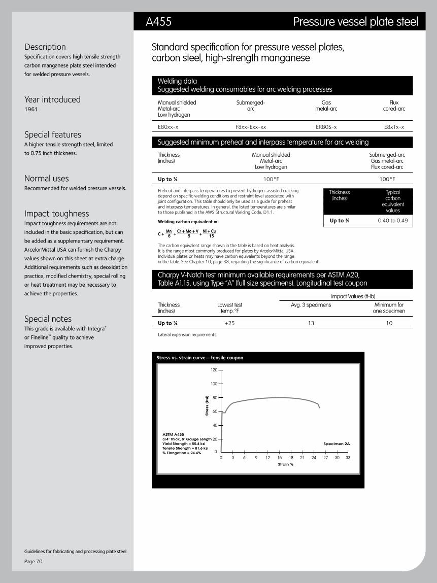
Guidelines for fabricating and processing plate steel
Page 70
Standard specification for pressure vessel plates, carbon steel, high-strength manganese
Welding dataSuggested welding consumables for arc welding processes
Manual shielded Submerged- Gas Flux Metal-arc arc metal-arc cored-arc Low hydrogen
E80xx-x F8xx-Exx-xx ER80S-x E8xTx-x
Suggested minimum preheat and interpass temperature for arc welding
Thickness Manual shielded Submerged-arc (inches) Metal-arc Gas metal-arc Low hydrogen Flux cored-arc
Up to ¾ 100°F 100°F
Preheat and interpass temperatures to prevent hydrogen-assisted cracking depend on specific welding conditions and restraint level associated with joint configuration. This table should only be used as a guide for preheat and interpass temperatures. In general, the listed temperatures are similar to those published in the AWS Structural Welding Code, D1.1.
Welding carbon equivalent =
C + Mn + Cr + Mo + V + Ni + Cu 6 5 15
The carbon equivalent range shown in the table is based on heat analysis. It is the range most commonly produced for plates by ArcelorMittal USA. Individual plates or heats may have carbon equivalents beyond the range in the table. See Chapter 10, page 38, regarding the significance of carbon equivalent.
Charpy V-Notch test minimum available requirements per ASTM A20,Table A1.15, using Type “A” (full size specimens). Longitudinal test coupon
Impact Values (ft-lb)
Thickness Lowest test Avg. 3 specimens Minimum for (inches) temp. °F one specimen
Up to ¾ +25 13 10
Lateral expansion requirements.
Thickness Typical (inches) carbon equivalent values
Up to ¾ 0.40 to 0.49
Stress vs. strain curve—tensile coupon
DescriptionSpecification covers high tensile strength carbon manganese plate steel intended for welded pressure vessels.
Year introduced1961
Special featuresA higher tensile strength steel, limited to 0.75 inch thickness.
Normal usesRecommended for welded pressure vessels.
Impact toughnessImpact toughness requirements are not included in the basic specification, but can be added as a supplementary requirement. ArcelorMittal USA can furnish the Charpy values shown on this sheet at extra charge. Additional requirements such as deoxidation practice, modified chemistry, special rolling or heat treatment may be necessary to achieve the properties.
Special notesThis grade is available with Integra® or Fineline™ quality to achieve improved properties.
A455 Pressure vessel plate steel

Page 71
DescriptionSpecification covers carbon-silicon plate steel primarily for intermediate and higher temperature service in welded boilers and other pressure vessels. This specification has been approved by the Department of Defense to replace Federal Specification QQ-S-691C and listed for listing in the DOD Index of Specifications and Standards.
Year introduced1964
Special featuresThis specification is available in three grades having different strength levels and is always produced to coarse austenitic grain size practices.
Normal usesA popular specification used when welded boilers and pressure vessels require intermediate and higher temperature steel.
Impact toughnessImpact toughness requirements are not available for this specification because it is produced to coarse, austenitic grain size practices.
Pressure vessel plate steel A515
Standard specification for pressure vessel plates, carbon steel, for intermediate and higher temperature service
Welding dataSuggested welding consumables for arc welding processes
Grade Manual shielded Submerged- Gas Flux Metal-arc arc metal-arc cored-arc Low hydrogen
60, 65, 70 E70xx, F7xx-Exxx, ER70S-x, E6xT-x, E7xT-x except E70xx-x E70xx-x F7xx-Exx-xx -2, -3, -10, -GS
Suggested minimum preheat and interpass temperature for arc welding
Grade Thickness Manual shielded Submerged-arc Notes (inches) Metal-arc Gas metal-arc Low hydrogen Flux cored-arc
60, 65 Up to ¾ incl None* None* Over ¾ to 10.5 incl 50°F 50°F Over 10.5 to 20.5 incl 150°F 150°F Over 20.5 225°F 225°F
70 Up to ¾ incl 50°F 50°F Over ¾ to 10.5 incl 150°F 150°F Over 10.5 to 20.5 incl 250°F 250°F Over 20.5 250°F 250°F
Preheat and interpass temperatures to prevent hydrogen-assisted cracking depend on specific welding conditions and restraint level associated with joint configuration. This table should only be used as a guide for preheat and interpass temperatures. In general, the listed temperatures are similar to those published in the AWS Structural Welding Code, D1.1.
Welding carbon equivalent =
C + Mn + Cr + Mo + V + Ni + Cu 6 5 15
The carbon equivalent range shown in the table is based on heat analysis. It is the range most commonly produced for plates by ArcelorMittal USA. Individual plates or heats may have carbon equivalents beyond the range in the table. See Chapter 10, page 38, regarding the significance of carbon equivalent.
Grade Thickness Typical (inches) carbon equivalent values
60 Up to 15 0.19 to 0.45
65 Up to 15 0.27 to 0.45
70 Up to 15 0.31 to 0.49
Stress vs. strain curve—tensile coupon
* When the base metal temperature is under 32°F, preheat the base metal to at least 70°F and maintain this temperature during welding.
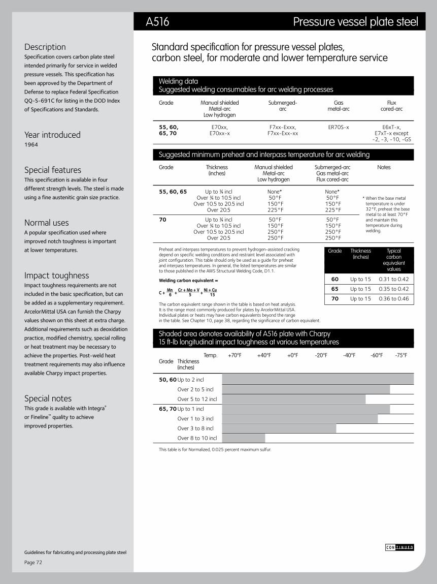
Guidelines for fabricating and processing plate steel
Page 72
Welding dataSuggested welding consumables for arc welding processes
Grade Manual shielded Submerged- Gas Flux Metal-arc arc metal-arc cored-arc Low hydrogen
55, 60, E70xx, F7xx-Exxx, ER70S-x E6xT-x, 65, 70 E70xx-x F7xx-Exx-xx E7xT-x except -2, -3, -10, -GS
Suggested minimum preheat and interpass temperature for arc welding
Grade Thickness Manual shielded Submerged-arc Notes (inches) Metal-arc Gas metal-arc Low hydrogen Flux cored-arc
55, 60, 65 Up to ¾ incl None* None* Over ¾ to 10.5 incl 50°F 50°F Over 10.5 to 20.5 incl 150°F 150°F Over 20.5 225°F 225°F
70 Up to ¾ incl 50°F 50°F Over ¾ to 10.5 incl 150°F 150°F Over 10.5 to 20.5 incl 250°F 250°F Over 20.5 250°F 250°F
Preheat and interpass temperatures to prevent hydrogen-assisted cracking depend on specific welding conditions and restraint level associated with joint configuration. This table should only be used as a guide for preheat and interpass temperatures. In general, the listed temperatures are similar to those published in the AWS Structural Welding Code, D1.1.
Welding carbon equivalent =
C + Mn + Cr + Mo + V + Ni + Cu 6 5 15
The carbon equivalent range shown in the table is based on heat analysis. It is the range most commonly produced for plates by ArcelorMittal USA. Individual plates or heats may have carbon equivalents beyond the range in the table. See Chapter 10, page 38, regarding the significance of carbon equivalent.
Shaded area denotes availability of A516 plate with Charpy15 ft-lb longitudinal impact toughness at various temperatures
Temp. +70°F +40°F +0°F -20°F -40°F -60°F -75°F Grade Thickness (inches)
50, 60 Up to 2 incl
Over 2 to 5 incl
Over 5 to 12 incl
65, 70 Up to 1 incl
Over 1 to 3 incl
Over 3 to 8 incl
Over 8 to 10 incl
This table is for Normalized, 0.025 percent maximum sulfur.
Grade Thickness Typical (inches) carbon equivalent values
60 Up to 15 0.31 to 0.42
65 Up to 15 0.35 to 0.42
70 Up to 15 0.36 to 0.46
DescriptionSpecification covers carbon plate steel intended primarily for service in welded pressure vessels. This specification has been approved by the Department of Defense to replace Federal Specification QQ-S-691C for listing in the DOD Index of Specifications and Standards.
Year introduced1964
Special featuresThis specification is available in four different strength levels. The steel is made using a fine austenitic grain size practice.
Normal usesA popular specification used where improved notch toughness is important at lower temperatures.
Impact toughnessImpact toughness requirements are not included in the basic specification, but can be added as a supplementary requirement. ArcelorMittal USA can furnish the Charpy values shown on this sheet at extra charge. Additional requirements such as deoxidation practice, modified chemistry, special rolling or heat treatment may be necessary to achieve the properties. Post-weld heat treatment requirements may also influence available Charpy impact properties.
Special notesThis grade is available with Integra® or Fineline™ quality to achieve improved properties.
Standard specification for pressure vessel plates, carbon steel, for moderate and lower temperature service
* When the base metal temperature is under 32°F, preheat the base metal to at least 70°F and maintain this temperature during welding.
t i n u e dc o n
A516 Pressure vessel plate steel
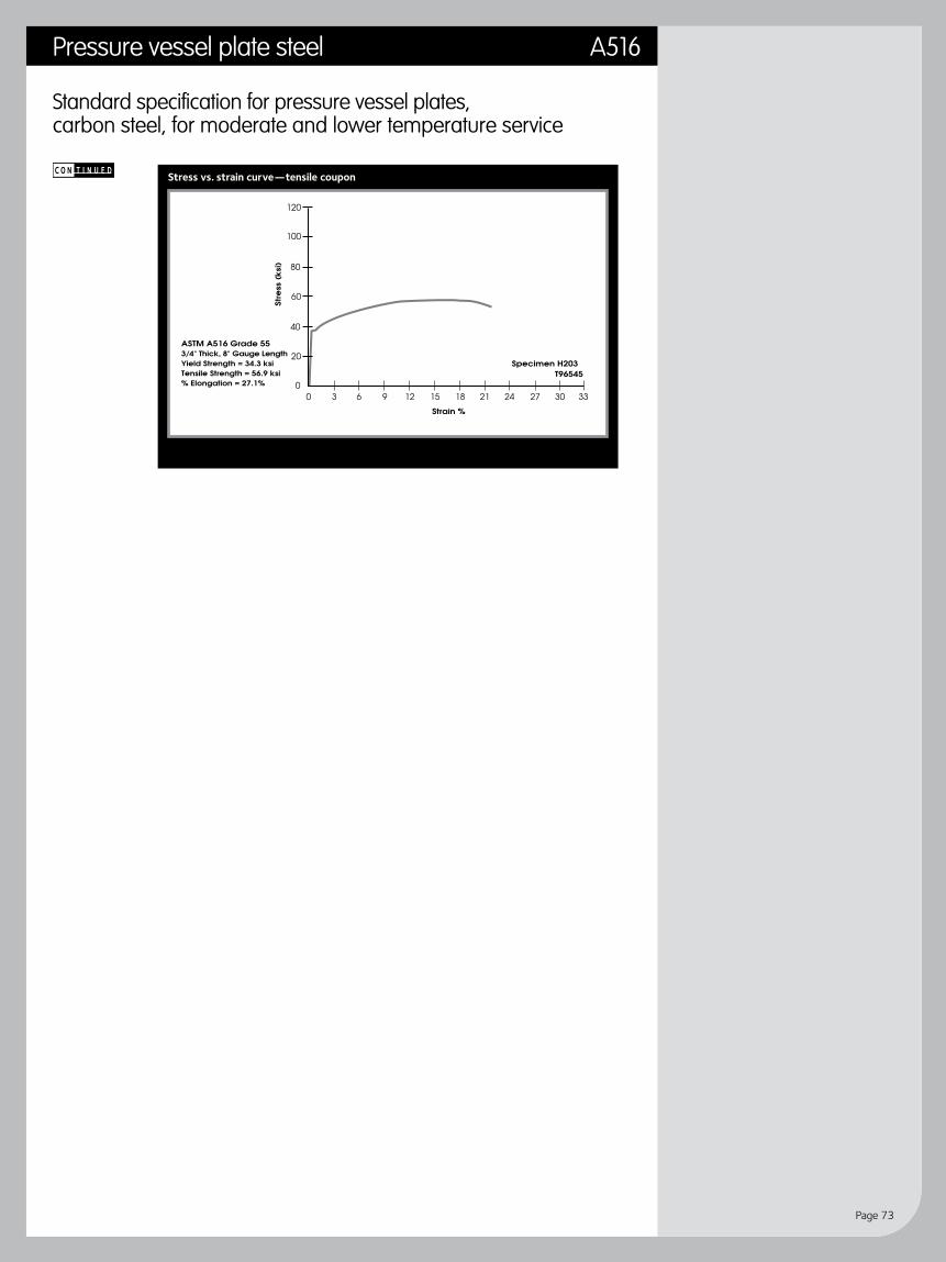
Page 73
Pressure vessel plate steel A516
Stress vs. strain curve—tensile coupon
Standard specification for pressure vessel plates, carbon steel, for moderate and lower temperature service
t i n u e dc o n
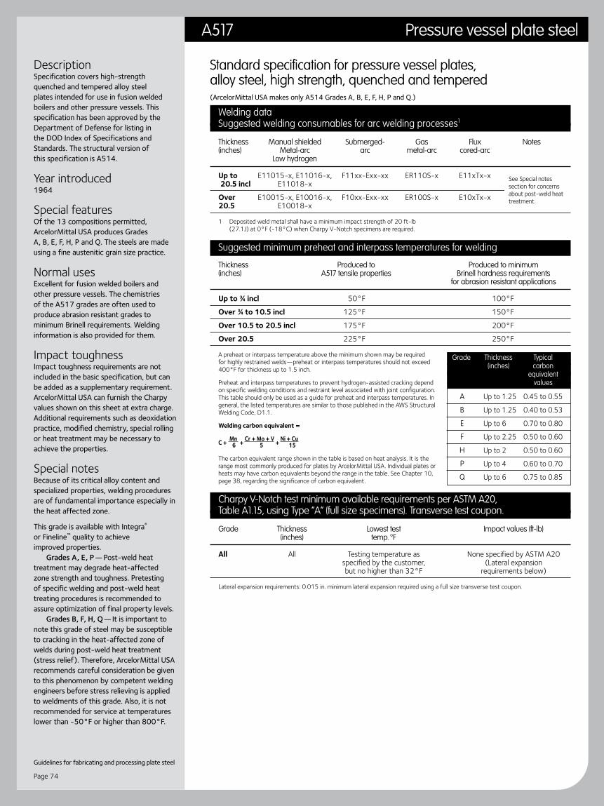
Guidelines for fabricating and processing plate steel
Page 74
Standard specification for pressure vessel plates, alloy steel, high strength, quenched and tempered(ArcelorMittal USA makes only A514 Grades A, B, E, F, H, P and Q.)
Welding dataSuggested welding consumables for arc welding processes1
Thickness Manual shielded Submerged- Gas Flux Notes (inches) Metal-arc arc metal-arc cored-arc Low hydrogen
Up to E11015-x, E11016-x, F11xx-Exx-xx ER110S-x E11xTx-x 20.5 incl E11018-x
Over E10015-x, E10016-x, F10xx-Exx-xx ER100S-x E10xTx-x 20.5 E10018-x
1 Deposited weld metal shall have a minimum impact strength of 20 ft-lb (27.1J) at 0°F (-18°C) when Charpy V-Notch specimens are required.
Suggested minimum preheat and interpass temperatures for welding
Thickness Produced to Produced to minimum (inches) A517 tensile properties Brinell hardness requirements for abrasion resistant applications
Up to ¾ incl 50°F 100°F
Over ¾ to 10.5 incl 125°F 150°F
Over 10.5 to 20.5 incl 175°F 200°F
Over 20.5 225°F 250°F
A preheat or interpass temperature above the minimum shown may be required for highly restrained welds—preheat or interpass temperatures should not exceed 400°F for thickness up to 1.5 inch.
Preheat and interpass temperatures to prevent hydrogen-assisted cracking depend on specific welding conditions and restraint level associated with joint configuration. This table should only be used as a guide for preheat and interpass temperatures. In general, the listed temperatures are similar to those published in the AWS Structural Welding Code, D1.1.
Welding carbon equivalent =
C + Mn + Cr + Mo + V + Ni + Cu 6 5 15
The carbon equivalent range shown in the table is based on heat analysis. It is the range most commonly produced for plates by ArcelorMittal USA. Individual plates or heats may have carbon equivalents beyond the range in the table. See Chapter 10, page 38, regarding the significance of carbon equivalent.
Charpy V-Notch test minimum available requirements per ASTM A20,Table A1.15, using Type “A” (full size specimens). Transverse test coupon.
Grade Thickness Lowest test Impact values (ft-lb) (inches) temp. °F
All All Testing temperature as None specified by ASTM A20 specified by the customer, (Lateral expansion but no higher than 32°F requirements below)
Lateral expansion requirements: 0.015 in. minimum lateral expansion required using a full size transverse test coupon.
Grade Thickness Typical (inches) carbon equivalent values
A Up to 1.25 0.45 to 0.55
B Up to 1.25 0.40 to 0.53
E Up to 6 0.70 to 0.80
F Up to 2.25 0.50 to 0.60
H Up to 2 0.50 to 0.60
P Up to 4 0.60 to 0.70
Q Up to 6 0.75 to 0.85
See Special notes section for concerns about post-weld heat treatment.
A517 Pressure vessel plate steel
DescriptionSpecification covers high-strength quenched and tempered alloy steel plates intended for use in fusion welded boilers and other pressure vessels. This specification has been approved by the Department of Defense for listing in the DOD Index of Specifications and Standards. The structural version of this specification is A514.
Year introduced1964
Special featuresOf the 13 compositions permitted, ArcelorMittal USA produces Grades A, B, E, F, H, P and Q. The steels are made using a fine austenitic grain size practice.
Normal usesExcellent for fusion welded boilers and other pressure vessels. The chemistries of the A517 grades are often used to produce abrasion resistant grades to minimum Brinell requirements. Welding information is also provided for them.
Impact toughnessImpact toughness requirements are not included in the basic specification, but can be added as a supplementary requirement. ArcelorMittal USA can furnish the Charpy values shown on this sheet at extra charge. Additional requirements such as deoxidation practice, modified chemistry, special rolling or heat treatment may be necessary to achieve the properties.
Special notesBecause of its critical alloy content and specialized properties, welding procedures are of fundamental importance especially in the heat affected zone.
This grade is available with Integra® or Fineline™ quality to achieve improved properties. Grades A, E, P—Post-weld heat treatment may degrade heat-affected zone strength and toughness. Pretesting of specific welding and post-weld heat treating procedures is recommended to assure optimization of final property levels. Grades B, F, H, Q—It is important to note this grade of steel may be susceptible to cracking in the heat-affected zone of welds during post-weld heat treatment (stress relief). Therefore, ArcelorMittal USA recommends careful consideration be given to this phenomenon by competent welding engineers before stress relieving is applied to weldments of this grade. Also, it is not recommended for service at temperatures lower than -50°F or higher than 800°F.

Page 75
DescriptionSpecification covers manganese-molybdenum and manganese-molybdenum-nickel alloy plate steel for use in the quenched and tempered condition for the construction of welded pressure vessels.
Year introduced1965
Special featuresThis specification is available in four types of chemical analysis and three classes of different strength levels.
Normal usesOften used in the beltline region of nuclear reactor vessels where the properties may be affected by high levels of radiation.
Impact toughnessImpact toughness requirements are not included in the basic specification, but can be added as a supplementary requirement. Additional requirements such as deoxidation practice, modified chemistry, special rolling or heat treatment may be necessary to achieve the properties.
Special notesThis alloy plate steel in the as-rolled condition is sensitive to cracking during transit and handling, particularly in the thicknesses over 1 in. or 2 in. It should be shipped in the as-rolled condition only with the mutual agreement of the manufacturer and fabricator.
This grade is available with Integra® or Fineline™ quality to achieve improved properties.
Pressure vessel plate steel A533
Standard specification for pressure vessel plates, alloy steel, quenched and tempered, manganese-molybdenum and manganese-molybdenum-nickel
Welding dataSuggested welding consumables for arc welding processes
Class Manual shielded Submerged- Gas Flux Metal-arc arc metal-arc cored-arc Low hydrogen
1 E80xx-x F8xx-Exx-xx ER80S-x E8xTx-x
2 E90xx-x F9xx-Exx-xx ER90S-x E9xTx-x
3 E100xx-x F10xx-Exx-xx ER100S-x E100T1-K3, E100T5-K3
Suggested minimum preheat and interpass temperature for arc welding
Grade Thickness Manual shielded Submerged-arc (inches) Metal-arc Gas metal-arc Low hydrogen Flux cored-arc
A, B, Up to 1 incl 200°F 200°F C, D 1 to 2 incl 300°F 300°F Over 2 400°F 400°F
Preheat and interpass temperatures to prevent hydrogen-assisted cracking depend on specific welding conditions and restraint level associated with joint configuration. This table should only be used as a guide for preheat and interpass temperatures. In general, the listed temperatures are similar to those published in the AWS Structural Welding Code, D1.1.
Welding carbon equivalent =
C + Mn + Cr + Mo + V + Ni + Cu 6 5 15
The carbon equivalent range shown in the table is based on heat analysis. It is the range most commonly produced for plates by ArcelorMittal USA. Individual plates or heats may have carbon equivalents beyond the range in the table. See Chapter 10, page 38, regarding the significance of carbon equivalent.
Grade Thickness Typical (inches) carbon equivalent values
A, B, Up to 12 0.48 to 0.67 C, D

Guidelines for fabricating and processing plate steel
Page 76
DescriptionSpecification covers heat treated carbon-manganese-silicon plate steel intended for fusion welded pressure vessels and structures.
Year introduced1965
Special featuresThis grade is available in three classes, Class 1 normalized and Class 2 and 3 quenched and tempered. The steel is made using a fine austenitic grain size practice.
Normal usesWelded pressure vessels.
Impact toughnessImpact toughness requirements are not included in the basic specification, but can be added as a supplementary requirement. ArcelorMittal USA can furnish the Charpy values shown on this sheet at extra charge. Additional requirements such as deoxidation practice, modified chemistry, special rolling or heat treatment may be necessary to achieve the properties.
Special notesThis grade is available with Integra® or Fineline™ quality to achieve improved properties.
Standard specification for pressure vessel plates, heat-treated carbon-manganese-silicon steel
Welding dataSuggested welding consumables for arc welding processes
Class Manual shielded Submerged- Gas Flux Notes Metal-arc arc metal-arc cored-arc Low hydrogen
1 E7015-x, E7016-x, F7xx-Exxx, ER70S-x E7xT-x except E7018-x, F7xx-Exx-xx -2, -3, -10, -GS E7028-x
2, 3 E8015-x, E8016-x F8xx-Exx-xx ER80S-x E8xTx-x
Suggested minimum preheat and interpass temperature for arc welding
Class Thickness Manual shielded Submerged-arc (inches) Metal-arc Gas metal-arc Low hydrogen Flux cored-arc
1, 2, 3 Up to 1 incl 70°F 70°F Over 1 to 10.5 incl 100°F 100°F Over 10.5 to 20.5 incl 150°F 150°F Over 20.5 to 6 incl 225°F 225°F
Preheat and interpass temperatures to prevent hydrogen-assisted cracking depend on specific welding conditions and restraint level associated with joint configuration. This table should only be used as a guide for preheat and interpass temperatures. In general, the listed temperatures are similar to those published in the AWS Structural Welding Code, D1.1.
Welding carbon equivalent =
C + Mn + Cr + Mo + V + Ni + Cu 6 5 15
The carbon equivalent range shown in the table is based on heat analysis. It is the range most commonly produced for plates by ArcelorMittal USA. Individual plates or heats may have carbon equivalents beyond the range in the table. See Chapter 10, page 38, regarding the significance of carbon equivalent.
Charpy V-Notch test minimum available requirements per ASTM A20,Table A1.15, using Type “A” (full size specimens). Longitudinal test coupon
Impact Values (ft-lb)
Class Thickness Lowest test Avg. 3 specimens Minimum for (inches) temp. °F one specimen
1 Up to 1 incl -80 15 12 Over 1 to 20.5 incl -75 15 12 Over 20.5 to 3 incl -75 13 10 Over 3 to 4 incl -50 13 10
2, 3 Up to 1 incl -90 20 15 Over 1 to 20.5 incl -90 20 15 Over 20.5 to 3 incl -75 15 12 Over 3 to 4 incl -50 15 12
If deposited weld metal should have a minimum impact strength, see the appropriate AWS specification for impact requirements of specific welding consumable designations.
Class Thickness Typical (inches) carbon equivalent values
1 Up to 4 0.39 to 0.54
2, 3 Up to 6 0.40 to 0.55
A537 Pressure vessel plate steel
t i n u e dc o n

Page 77
Pressure vessel plate steel A537
Standard specification for pressure vessel plates, heat-treated carbon-manganese-silicon steel
Stress vs. strain curve—tensile coupon t i n u e dc o n

Guidelines for fabricating and processing plate steel
Page 78
Standard specification for pressure vessel plates, carbon steel, high strength, for moderate and lower temperature service
Welding dataSuggested welding consumables for arc welding processes
Grade Manual shielded Submerged- Gas Flux Metal-arc arc metal-arc cored-arc Low hydrogen
All E80xx-x, F8xx-Exx-xx, ER80S-x, E8xTx-x, E90xx-x F9xx-Exx-xx ER90S-x E9xTx-x
Suggested minimum preheat and interpass temperature for arc welding
Grade Thickness Manual shielded Submerged-arc (inches) Metal-arc Gas metal-arc Low hydrogen Flux cored-arc
All Up to 0.5 incl 100°F 100°F Over 0.5 to 1 incl 150°F 150°F
Preheat and interpass temperatures to prevent hydrogen-assisted cracking depend on specific welding conditions and restraint level associated with joint configuration. This table should only be used as a guide for preheat and interpass temperatures. In general, the listed temperatures are similar to those published in the AWS Structural Welding Code, D1.1.
Welding carbon equivalent =
C + Mn + Cr + Mo + V + Ni + Cu 6 5 15
The carbon equivalent range shown in the table is based on heat analysis. It is the range most commonly produced for plates by ArcelorMittal USA. Individual plates or heats may have carbon equivalents beyond the range in the table. See Chapter 10, page 38, regarding the significance of carbon equivalent.
Charpy V-Notch test minimum available requirements per ASTM A20,Table A1.15, using Type “A” (full size specimens). Longitudinal test coupon
Impact Values (ft-lb)
Grade Thickness Lowest test Avg. 3 specimens Minimum for (inches) temp. °F one specimen
All Up to 1 -50 20 15
Thickness Typical (inches) carbon equivalent values
Up to 1 0.44 to 0.52
Stress vs. strain curve—tensile coupon
A612 Pressure vessel plate steel
DescriptionSpecification covers killed carbon-manganese-silicon plate steel intended for welded pressure vessels in service at moderate and lower temperatures.
Year introduced1970
Special featuresThis steel is killed and made using a fine austenitic grain size practice.
Normal usesWelded pressure vessels requiring moderate or lower temperatures, particularly railway tank cars.
Impact toughnessImpact toughness requirements are not included in the basic specification, but can be added as a supplementary requirement. ArcelorMittal USA can furnish the Charpy values shown on this sheet at extra charge. Additional requirements such as deoxidation practice, modified chemistry, special rolling or heat treatment may be necessary to achieve the properties.
Special notesThis grade is available with Integra® or Fineline™ quality to achieve improved properties. Post-weld heat treatment may degrade heat-affected zone strength and toughness. Pretesting of specific welding and post-weld heat treating procedures is recommended to assure optimization of final property levels.

Page 79
DescriptionSpecification covers carbon-manganese plate steel intended primarily for service in welded pressure vessels where improved low temperature notch toughness is important.
Year introduced1972
Special featuresThis material is available in three grades having different strength levels. The steel is made using a fine austenitic grain size practice.
Normal usesWelded pressure vessels where low temperature notch toughness is important.
Impact toughnessImpact toughness requirements are not included in the basic specification, but can be added as a supplementary requirement. ArcelorMittal USA can furnish the Charpy values shown on this sheet at extra charge. Additional requirements such as deoxidation practice, modified chemistry, special rolling or heat treatment may be necessary to achieve the properties.
Special notesThis grade is available with Integra® or Fineline™ quality to achieve improved properties.
Pressure vessel plate steel A662
Standard specification for pressure vessel plates, carbon-manganese-silicon steel for moderate and lower temperature service
Welding dataSuggested welding consumables for arc welding processes
Grade Manual shielded Submerged- Gas Flux Metal-arc arc metal-arc cored-arc Low hydrogen
A, B, C E70xx, F7xx-Exxx, ER70S-x E7xT-x except E70xx-x F7xx-Exx-xx -2, -3, -10, -GS
Suggested minimum preheat and interpass temperature for arc welding
Grade Thickness Manual shielded Submerged-arc (inches) Metal-arc Gas metal-arc Low hydrogen Flux cored-arc
A, B, C Up to 1 incl 50°F 50°F Over 1 to 2 incl 100°F 100°F
Preheat and interpass temperatures to prevent hydrogen-assisted cracking depend on specific welding conditions and restraint level associated with joint configuration. This table should only be used as a guide for preheat and interpass temperatures. In general, the listed temperatures are similar to those published in the AWS Structural Welding Code, D1.1.
Welding carbon equivalent =
C + Mn + Cr + Mo + V + Ni + Cu 6 5 15
The carbon equivalent range shown in the table is based on heat analysis. It is the range most commonly produced for plates by ArcelorMittal USA. Individual plates or heats may have carbon equivalents beyond the range in the table. See Chapter 10, page 38, regarding the significance of carbon equivalent.
Charpy V-Notch test minimum available requirements per ASTM A20,Table A1.15, using Type “A” (full size specimens). Longitudinal test coupon
Impact Values (ft-lb)
Grade Thickness Lowest test Avg. 3 specimens Minimum for (inches) temp. °F one specimen
A Up to 2 -75 13 10
B Up to 2 -60 13 10
C Up to 2 -50 15 12
Grade Thickness Typical (inches) carbon equivalent values
A, B, C Up to 2 0.37 to 0.48

Guidelines for fabricating and processing plate steel
Page 80
Standard specification for pressure vessel plates, high-strength, low-alloy steel
Welding dataSuggested welding consumables for arc welding processes
Grade Manual shielded Submerged- Gas Flux Metal-arc arc metal-arc cored-arc Low hydrogen
B E70xx, E70xx-x F7xx-Exxx ER70S-x E7xT-x
C E80xx-x F8xx-Exx-xx ER80S-x E8xTx-x
Suggested minimum preheat and interpass temperature for arc welding
Grade Thickness Manual shielded Submerged-arc (inches) Metal-arc Gas metal-arc Low hydrogen Flux cored-arc
B, C Up to ¾ incl 50°F 50°F Over ¾ to 1 incl 100°F 100°F Over 1 to 10.5 incl 150°F 150°F Over 10.5 to 2 incl 200°F 200°F Over 2 250°F 250°F
Preheat and interpass temperatures to prevent hydrogen-assisted cracking depend on specific welding conditions and restraint level associated with joint configuration. This table should only be used as a guide for preheat and interpass temperatures. In general, the listed temperatures are similar to those published in the AWS Structural Welding Code, D1.1.
Welding carbon equivalent =
C + Mn + Cr + Mo + V + Ni + Cu 6 5 15
The carbon equivalent range shown in the table is based on heat analysis. It is the range most commonly produced for plates by ArcelorMittal USA. Individual plates or heats may have carbon equivalents beyond the range in the table. See Chapter 10, page 38, regarding the significance of carbon equivalent.
Shaded area denotes availability of A737 Grade B and C plate withCharpy 15 ft-lb longitudinal impact toughness at various temperatures
Temp. +70°F +40°F +0°F -20°F -40°F -60°F -80°F Grade Thickness (inches)
B Up to 4
C Up to 3 incl
C Over 3 to 6 incl
This table is for Normalized, 0.010 percent maximum sulfur.
Grade Thickness Typical (inches) carbon equivalent values
B Up to 4 0.38 to 0.46
C Up to 4 0.45 to 0.57
DescriptionSpecification covers high-strength and low-alloy plate steel for service in welded pressure vessels and piping components. The structural version of this specification is A633.
Year introduced1976
Special featuresThis specification is available in two different strength levels. The steel is made using a fine austenitic grain size practice.
Normal usesUsed for piping and pressure vessel applications where high strength and improved toughness are required.
Impact toughnessImpact toughness requirements are not included in the basic specification, but can be added as a supplementary requirement. ArcelorMittal USA can furnish the Charpy values shown on this sheet at extra charge. Additional requirements such as deoxidation practice, modified chemistry, special rolling or heat treatment may be necessary to achieve the properties.
Special notesBecause of its critical alloy content and specialized properties, welding procedures are of fundamental importance, especially in the heat affected zone.
This grade is available with Integra® or Fineline™ quality to achieve improved properties. Post-weld heat treatment may degrade heat-affected zone strength and toughness. Pretesting of specific welding and post-weld heat treating procedures is recommended to assure optimization of final property levels.
Stress vs. strain curve—tensile coupon
A737 Pressure vessel plate steel

Page 81
DescriptionSpecification covers heat treated carbon-manganese-silicon plate steel intended for use in welded pressure vessels at moderate and lower temperature service.
Year introduced1976
Special featuresThis specification is available in three grades with different strength levels.
Normal usesUsed for welded pressure vessels requiring moderate and lower temperature service.
Impact toughnessImpact toughness requirements are not included in the basic specification, but can be added as a supplementary requirement. Additional requirements such as deoxidation practice, modified chemistry, special rolling or heat treatment may be necessary to achieve the properties. The impact toughness of this specification is strongly influenced by chemistry, heat treatment and required post-weld heat treatment. Contact ArcelorMittal USA with your specific requirements.
Special notesGrade A is the material that, prior to 1984, was covered by specification A738 without a grade designation.
This grade is available with Integra® or Fineline™ quality to achieve improved properties.
Pressure vessel plate steel A738
Standard specification for pressure vessel plates, heat-treated, carbon-manganese-silicon steel, for moderate and lower temperature service
Welding dataSuggested welding consumables for arc welding processes
Grade Thickness Manual shielded Submerged- Gas Flux (inches) Metal-arc arc metal-arc cored-arc Low hydrogen
A All E80xx-x F8xx-Exxx, ER80S-x E8xTx-x F8xx-Exx-xx
B All E90xx-x F9xx-Exx-xx ER90S-x E9xTx-x
C Up to 20.5 incl E90xx-x F9xx-Exx-xx ER90S-x E9xTx-x Over 20.5 E80xx-x F8xx-Exx-xx ER80S-x E8xTx-x
Suggested minimum preheat and interpass temperature for arc welding
Grade Thickness Manual shielded Submerged-arc (inches) Metal-arc Gas metal-arc Low hydrogen Flux cored-arc
A, B, C Up to 0.5 incl 100°F 100°F Over 0.5 to 1 incl 150°F 150°F Over 1 to 2 incl 200°F 200°F Over 2 250°F 250°F
Preheat and interpass temperatures to prevent hydrogen-assisted cracking depend on specific welding conditions and restraint level associated with joint configuration. This table should only be used as a guide for preheat and interpass temperatures. In general, the listed temperatures are similar to those published in the AWS Structural Welding Code, D1.1.
Welding carbon equivalent =
C + Mn + Cr + Mo + V + Ni + Cu 6 5 15
The carbon equivalent range shown in the table is based on heat analysis. It is the range most commonly produced for plates by ArcelorMittal USA. Individual plates or heats may have carbon equivalents beyond the range in the table. See Chapter 10, page 38, regarding the significance of carbon equivalent.
Grade Thickness Typical (inches) carbon equivalent values
A, B Up to 6 0.46 to 0.54

Guidelines for fabricating and processing plate steel
Page 82
Standard specification for plate steel for pressure vessels produced by thermo-mechanical-control-process (TMCP)
Welding dataSuggested welding consumables for arc welding processes
Manual shielded Submerged- Gas Flux Metal-arc arc metal-arc cored-arc Low hydrogen
E7015-x, E7016-x, F7xx-Exxx, ER70S-x E7xT-x except E7018-x, E7028-x F7xx-Exx-xx -2, -3, -10, -GS
Suggested minimum preheat and interpass temperature for arc welding
Thickness Manual shielded Submerged-arc Notes (inches) Metal-arc Gas metal-arc Low hydrogen Flux cored-arc
Up to ¾ incl None* None*
Over ¾ to 10.5 incl 70°F 70°F
Over 10.5 to 20.5 incl 150°F 150°F
Over 20.5 to 4 incl 225°F 225°F
Preheat and interpass temperatures to prevent hydrogen-assisted cracking depend on specific welding conditions and restraint level associated with joint configuration. This table should only be used as a guide for preheat and interpass temperatures. In general, the listed temperatures are similar to those published in the AWS Structural Welding Code, D1.1.
Welding carbon equivalent =
C + Mn + Cr + Mo + V + Ni + Cu 6 5 15
The carbon equivalent range shown in the table is based on heat analysis. It is the range most commonly produced for plates by ArcelorMittal USA. Individual plates or heats may have carbon equivalents beyond the range in the table. See Chapter 10, page 38, regarding the significance of carbon equivalent.
* When the base metal temperature is under 32°F, preheat the base metal to at least 70°F and maintain this temperature during welding.
Thickness Typical(inches) carbon equivalent values
Up to 20.5 incl 0.30 to 0.35
Over 20.5 to 4 incl 0.35 to 0.40
DescriptionSpecification covers plate steel produced by the thermo-mechanical-control-process (TMCP) (see Chapter 4). The plates are intended primarily for use in welded pressure vessels.
Year introduced1985
Special featuresThis specification is available in two strength levels.
Normal usesUsed for welded pressure vessels.
Impact toughnessImpact toughness requirements are a part of the basic specification. Test results of 10 mm x 10 mm specimens shall meet an average minimum value of 15 ft-lb at -40°F. Tests per ASTM A20.
Special notesThis grade is available with Integra® or Fineline™ quality to achieve improved properties. Post-weld heat treatment may degrade heat-affected zone strength and toughness. Pretesting of specific welding and post-weld heat treating procedures is recommended to assure optimization of final property levels. The TMCP heating and rolling practices are defined in Fig. X1.1 of specification A841.
A841 Pressure vessel plate steel

Page 83
Physical properties of plate steel

Guidelines for fabricating and processing plate steel
Page 84
Physical Properties of Plate Steel
Item English Units Metric Units
Specific gravity 7.9 7.9
Density 490 lb/ft3 7850 kg/m3
Melting point 2370°F–2640°F 1300°C-1450°C
Specific heat 0.12 Btu 0.12 (Cal) (lb) (°F) (gr) (°C)
Linear coefficient of 6.5 x 10- 6 1 (11.7) x 10-6 1
thermal expansion F C
Volumetric coefficient 19.5 x 10- 6 1 (35.1) x 10-6 1 of thermal expansion F C
Thermal conductivity at 60°F 34 (Btu) 0.14 (Cal) (hr) (ft) (°F) (sec) (cm) (°C)
Electrical resistivity at 60°F 17 x 10-8 (ohm-meters)
Speed of sound through steel 18,000 ft/sec 5490 m/sec
Young’s modulus 29,000,000 lb 207,000 MPa of elasticity (in)2
Poisson’s ratio, 0.3 in the elastic range and 0.5 in the plastic range
Bulk modulus 23,000,000 lb 159,000 MPa (in)2
Shear modulus 12,000,000 lb 83,000 MPa (in) 2
Emissivity of polished .07 at 100°F .07 at 38°C metal surface .10 at 500°F .10 at 260°C .14 at 1000°F .14 at 540°C
Emissivity of oxidized 0.80 0.80 plate steel at 60°F
The properties listed above vary with the chemistry of the plate steel. The values shown are typical for non-alloy plate grades. If more accuracy is required, refer to a physics handbook.
Physical properties of plate steelChapter 13

Page 85
Glossary

Guidelines for fabricating and processing plate steel
Page 86
Accelerated cooling. Cooling the plate with water immediately following the final rolling operation. Generally the plate is water cooled from about 1400°F to approximately 1100°F.
Aging. A time-dependent change in the properties of certain steels that occurs at ambient or moderately elevated temperatures after hot-working, after a thermal treatment (quench aging), or after a cold-working operation (strain aging).
Allow steel. Steel is considered to be an alloy steel when either (1) the maximum of the range given for the content of alloying elements exceeds one or more of the following percentages: manganese 1.65 percent, silicon 0.60 percent, copper 0.60 percent; or (2) a definite range or definite minimum quantity of those elements considered alloys is specified. For example, chromium, molybdenum and nickel.
Annealing. A thermal cycle involving heating to, and holding at, a suitable temperature and then cooling at a suitable rate, for such purposes as reducing hardness, improving machinability, facilitating cold-working, producing a desired microstructure, or obtaining desired mechanical or other properties.
Austenitizing. The process of forming the austenite phase by heating a ferrous alloy into the transformation range (partial austenitizing above the lower critical temperature) or above this range (complete austenitizing above the upper critical temperature).
Bainite. A decomposition product of austenite consisting of an aggregate of ferrite and carbide. In general, it forms at temperatures lower than those where very fine pearlite forms, and higher than those where martensite begins to form on cooling.
Brinell Hardness Number (HB). A measure of hardness determined by the Brinell hardness test, in which a hard steel ball under a specific load is forced into the surface of the test material. The number is derived by dividing the applied load by the surface area of the resulting impression.
Camber. As it relates to plates, camber is the horizontal edge curvature in the length, measured over the entire length of the plate.
Carbon steel. By common custom, steel is considered to be carbon steel when no minimum content is specified or required for aluminum, boron, chromium, cobalt, columbium, molybdenum, nickel, titanium, tungsten, vanadium, zirconium or any other element added to obtain a desired alloying effect; when the specified minimum for copper does not exceed 0.40 percent; or when the maximum content specified for any of the following elements does not exceed the percentages: manganese 1.65 percent, silicon 0.60 percent, copper 0.60 percent. Small amounts of alloying elements may be present and are considered incidental.
Carburizing. A process in which an austenitized ferrous material is brought into contact with a carbonaceous atmosphere or medium of sufficient carbon potential as to cause absorption of carbon at the surface and, by diffusion, create a concen tration gradient. Hardening by quenching follows.
Cold cracking. Develops in a weldment after solidification. It forms within hours or days after welding, depending on steel grade, residual stresses and hydrogen content. Proper processing will prevent this problem.
Continuous casting. The most popular technique for solidifying steel. Involves pouring steel into an intermediate tundish before entering a water-cooled, copper mold. A solidifying steel strand is drawn through a machine where it continues to cool before exiting the machine.
Controlled cooling. A process by which steel is cooled from an elevated temperature in a pre determined manner to avoid hardening, cracking or internal damage, or to produce desired microstructure or mechanical properties.
Controlled-rolling. A rolling practice that improves mechanical properties by controlling the related parameters of time-temperature and deformation.
Glossary
Page 87
Corrosion. The gradual degradation of steel caused by atmosphere, moisture or other agents. Can also lead to cracking of various forms, e.g., stress corrosion cracking, hydrogen induced cracking and sulfide stress cracking.
Creep. A time-dependent deformation of steel occurring under conditions of elevated temperature accompanied by stress intensities well within the apparent elastic limit for the temperature involved.
Critical range (Temperatures). Synonymous with “transformation range,” which is the preferred term. (See Austenitizing)
Decarburization. The loss of carbon from the surface of steel as a result of heating in a medium that reacts with the carbon.
Deoxidation. A process used during melting and refining of steel to remove and/or chemically combine oxygen from the molten steel to prevent porosity in the steel when it is solidified.
Ductility. The ability of a material to deform plastically without fracturing, usually measured by elongation or reduction of area in a tension test, or, for flat products such as sheet, by height of cupping in an Erichsen test.
Elastic limit. The greatest stress a steel can see without permanent deformation.
Elongation. A measure of ductility, determined by the amount of permanent extension achieved by a tension test specimen, and expressed as a percentage of that specimen’s original gauge length (as: 25 percent in 2 in.).
End-quench hardenability test (Jominy test). A method for determining the hardenability of steel by water-quenching one end of an austenitized cylindrical test specimen and measuring the resulting hardness at specified distances from the quench end.
Endurance limit. The maximum cyclic stress, usually expressed in pounds per square inch, to which a metal can be subjected for indefinitely long periods without damage or failure.
Extensometer. An instrument capable of measuring small magnitudes of strain occurring in a specimen during a tension test, conventionally used when a stress-strain diagram is to be plotted.
Ferrite. The room temperature form of alpha iron, one of the two major constituents of steel (with cementite) in which it acts as the solvent to form solid solutions with such elements as manganese, nickel, silicon and, to a small degree, carbon.
Flame hardening. A hardening process in which the surface is heated by direct flame impingement and then quenched.
Grain size number. An arbitrary number calculated from the average number of individual crystals, or grains, that appear on the etched surface of a specimen.
Hardenability. The property of steel that determines the depth and distribution of hardness induced on cooling after austenitizing.
Hardness. The resistance of a material to plastic deformation. Usually measured in steels by the Brinell, Rockwell or Vickers indentation-hardness test methods.
Heat affected zone. Portion of the base plate, that was heated during a thermal cutting or welding operation.
High-strength, low-alloy steels. A specific group of steels with chemical compositions especially developed to impart higher mechanical properties and, in certain instances, improved atmospheric corrosion resistance relative to conventional carbon steel. It is not considered to be an alloy steel as previously described, even though use of any intentionally added alloy content would technically qualify it as such. Typical grades are A572 and A588.
Glossary

Guidelines for fabricating and processing plate steel
Page 88
Ingot casting. A technique for solidifying molten steel by pouring it into cast iron ingot molds.
Impact test. A test for determining the ability of a steel to withstand high-velocity loading, as measured by the energy (in ft-lb) that a notched-bar specimen absorbs upon fracturing.
Martensite. A microconstituent or structure in hardened steel, characterized by an acicular or needle-like pattern, and having the maximum hardness of any of the decomposition products of an austenite.
Mechanical properties. Properties that reveal the reactions, elastic and inelastic, of a material to applied forces. Sometimes defined erroneously as “physical properties.”
Microstructure. The metallurgical structure for a steel determined by polishing and etching samples and examining them at high magnifications using light or electron optical methods. Examples include ferrite, pearlite, bainite and martensite.
Modulus of elasticity (Young’s modulus). A measure of stiffness, or rigidity, expressed in pounds per square inch. Developed from the ratio of the stress, as applied to a tension test specimen, to the corresponding strain or elongation of the specimen. Applicable for tensile loads below the elastic limit of the material.
Notch (impact) toughness. An indication of a steel’s capacity to absorb energy when a stress concentrator or notch is present. Examples are Charpy V-Notch, dynamic tear, drop-weight and drop-weight tear tests.
Normalizing. A thermal treatment consisting of heating to a suitable temperature above the transformation range and then cooling in still air. Usually employed to improve toughness or machinability, or as a preparation for further heat treatment.
Pearlite. A microconstituent of iron and steel consisting of a lamellar aggregate of ferrite and cementite (a compound of iron and carbon—Fe3C).
Physical properties. Properties pertaining to the physics of a material, such as density, electrical conductivity and coefficient of thermal expansion. Not to be confused with mechanical properties.
Post-weld heat treatment (PWHT). Also referred to as stress relieving, this process is used to soften the heat affected zones and relieve residual stresses created during welding.
Preheating. A process to heat plate prior to thermal cutting or welding to prevent hard areas or cracking.
Proportional limit. The maximum stress at which strain remains directly proportional to stress.
Quench cracking. Occurs in medium carbon and alloy steels during quenching and tempering heat treatment. Proper part design, heat treating and quenching practices will prevent this problem.
Quenching and tempering. A thermal process used to increase the hardness and strength of steel. It consists of austenitizing, then cooling at a rate sufficient to achieve partial or complete transformation to martensite. Tempering involves reheating to a temperature below the transformation range and then cooling at any rate desired. Tempering improves ductility and toughness, but reduces the quenched hardness by an amount determined by the tempering temperature and time.
Reduction of area. A measure of ductility determined by the difference between the original cross-sectional area of a tension test specimen and the area of its smallest cross-section at the point of fracture. Expressed as a percentage of the original area.
Rockwell hardness (HRB OR HRC). A measure of hardness determined by the Rockwell hardness tester, by which a diamond spheroconical penetrator (Rockwell C scale) or a hard steel ball (Rockwell B scale) is forced into the surface of the test material under sequential minor and major loads. The difference between the depths of impressions from the two loads is read directly on the arbitrarily calibrated dial as the Rockwell hardness value.
Glossary

Page 89
Spherodized annealing. A prolonged heating of the steel in a controlled-atmosphere furnace at or near the lower critical point, followed by retarded cooling in the furnaces, to produce a lower hardness than can be obtained by regular annealing.
Steckel mill. A rolling mill design with heated coiling furnaces on each side to allow efficient rolling of thin plate products.
Stress-cracking. Occurs during the thermal cutting of high carbon and alloy steels at the cut edges. Proper processing, which may include preheating, will prevent this problem.
Stress relieving. A thermal cycle involving heating to a suitable temperature, usually 1000°F to 1200°F, holding long enough to reduce residual stresses from either cold deformation or thermal treatment, and then cooling slowly enough to minimize the development of new residual stresses.
Temper embrittlement. Brittleness that results when certain steels are held within, or are cooled slowly through, a specific range of temperatures below the transformation range. The brittleness is revealed by notched-bar impact tests at or below room temperature.
Tempering. See Quenching and tempering.
Tensile strength. The maximum tensile stress in pounds per square inch that a material is capable of sustaining, as developed by a tension test.
Tension test. A test in which a machined or full-section specimen is subjected to a measured axial load sufficient to cause fracture. The usual information derived includes the elastic properties, ultimate tensile strength, and elongation and reduction of area.
Thermal cutting. A process for cutting plate steel to size using an oxy-fuel, plasma or laser heat source. Oxidation or burning of steel is initiated by melting with the heat source and then a stream of high purity oxygen continues the reaction.
Thermo-mechanical-controlled-processing (TMCP). A term referring to special rolling practices that use controlled-rolling and/or accelerated cooling.
Thermal treatment. Any operation involving the heating and cooling of a metal or alloy in the solid state to obtain the desired microstructure or mechanical properties.
Tool steel. Steel with a higher carbon and alloy content. Used to make tools for cutting, forming or otherwise shaping a material into a part or component for a definite use.
Toughness. An indication of a steel’s capacity to absorb energy, particularly in the presence of a notch or a crack.
Transformation ranges. Those ranges of temperatures within which austenite forms during heating and transforms during cooling.
Transformation temperatures. The temperature at which a change in phase occurs. The term is sometimes used to denote the limiting temperature of a transformation range.
Yield point. The minimum stress at which a marked increase in strain occurs without an increase in stress, as indicated by a sharp knee in the stress-strain curve.
Yield strength. The stress at which a material exhibits a specified deviation from the proportionality of stress to strain. The deviation is expressed in terms of strain, and in the offset method, usually a strain of 0.2 percent is specified.
Young's modulus. See Modulus of elasticity.
Glossary

Guidelines for fabricating and processing plate steel
Page 90


ArcelorMittal USAT +1 800 966 5352usa.arcelormittal.com 9/17 Printed in the U.S.