guidelines for design and project planning
TRANSCRIPT

Translated: December 2013; Eml
Guidelines for
Design and
Project Planning

Page 1
What a constructing architect is expected to know about drains and sewers ............ 2
Legend ................................................................................................................................ 3
Drainage-Technical Abbreviations ................................................................................... 5
Rules for service pipe connections to main sewer and drainage installations ........... 6
Cleaning accesses ............................................................................................................ 7
Drainage from basement light boxes/shaft drains ......................................................... 9
Drainage from the external stairwell drains .................................................................. 11
Manhole wells .................................................................................................................. 13
Rainwater from roof ........................................................................................................ 14
Dry pipes .......................................................................................................................... 15
Sand traps ........................................................................................................................ 15
Construction Outline ....................................................................................................... 17
Light well construction outline ....................................................................................... 17
Drain installations ........................................................................................................... 18
Perimeter drains at basement walls ............................................................................... 22
Drainage from special rooms ......................................................................................... 22
Conditions for foundations, excavation and foundation conditions .......................... 23
The laying of sewers ....................................................................................................... 26
The laying of flexible drainage and sewer pipes .......................................................... 28
Municipal information ..................................................................................................... 28
Did you remember that? ................................................................................................. 31
Note: on the floor/situation plan .................................................................................... 32
Oil and petrol (fuel) separators ...................................................................................... 33
Grease and fat separators .............................................................................................. 34
Pump wells ....................................................................................................................... 34
Anti-flooding sewer and drainage devices .................................................................... 37
Acid neutralizers .............................................................................................................. 40
Rainwater Systems .......................................................................................................... 40
Local drainage / use (LDR) ............................................................................................. 41
Drainage options ............................................................................................................. 42
Infiltration (seepage) of rainwater .................................................................................. 43
Holding tanks ................................................................................................................... 46
Dimensioning according to the norm ............................................................................ 47
Design of ventilated wastewater pipes and rainwater pipes ....................................... 49

Page 2
What a constructing architect is expected to know about drains and sewers
It is expected that, during the course of their training,
constructing architects familiarize themselves with the issues, which are not written in italics.
The topics, which are written in italics, are for those who wish to acquire further knowledge in the field.

Page 3
Legend The legend on drainage and sewage drawings
New sewer and drainage pipes
Common/Mutual System All the pipes have the same legend Bold letters Labelling(from left) - dimensions in mm - material description - slope (slope direction indicated with arrow on main sewer pipe) - level
Separate System Sewage system (solid line) Rainwater system (broken line) Bold line
Drainage System Drain pipe (broken line with intermediate dots) Bold line
Crossing pipes The lowest pipe is discontinued Levels should be added to drawing
Water seal/trap
Cleaning access for solitary pipe
Change of dimension via reduction pipe
Cleaning access for stack (vertical pipe), solitary pipe
Change in pipe slope A bend can be used to achieve this.
Existing sewer and drainage pipes
Existing system (short broken lines, irrespective of system) Thin lines
Existing system, to plugged and disused.
Afpr. = to be plugged Thin lines
Installations
Kitchen sink, single and double.
WC-bowl with built-in water trap
Cleaning-sink
WC-bowl without built-in water trap
Washbasin
Urinal Wall mounted urinal
Bathtub
The type can be shown, e.g., sitz bath, or corner bath, etc.
Urinal
The number of urinal spaces should be indicated
Bidet
Wells and separators

Page 4
Access wells (manhole) with bottom furrow and side-drilled rainwater lead-in (“splash”)
1 m. concrete well with bottom level (BK) at 17.20 and well cover at level (DK) 19.25, and a rainwater lead-in at level 18.70
Circular inspection well with water seal (trap) and tight cover.
With sand or sludge trap Diameter 300 mm. Level of water trap (water table in trap) 9.28 Lead-in at level 10.05
315 mm cleaning and inspection well (flushing well)
BK 20.25
Drain well (gully)(circular) with water trap and surface grille (grating)
With sand/sludge separator. Diameter 200mm.
Inspection chamber with bottom furrow
The level of the cover is normally not stated The dimensions given = internal measurements
Drain well (gully)(circular) with water trap, tight cover and roof downpipe
Cast-in bend With sand/sludge separator
Manhole well with bottom furrow
Diameter 1.25 m and bottom level 43.20 (middle) The internal in-flow to left. To the right is the external. Materials for the vertical pipe can be given (or shown on detail drawings)
Drain well (gully)(rectangular) with water trap and grille (grating), and sand/sludge separator
Dimension 300x400 mm
Pump well with automatic pump
Diameter 1m. In-flow at level 13.20. Bottom in level 12.20 The actual form of the pump well is normally not shown on sewer plan
Drain well (gully)(circular) with rectangular grille (grating)
With sand/sludge separator
Sand or sludge separator with inlet and outlet (with water trap)
315 mm PP with water level in trap.
Cesspool well (soak well
where water trickles in) The diameter is given
Tank for single family house (according to the Single Chamber Principle)
E.g.: septic tank Diameter 1.25, bottom level 17.10 Submerged in and outflows in levels 19.85 and 19.80, respectively
Infiltration trench (gravel-filled soakways)
The dimensions are given
Settling tank
E.g.: ”Trixtank” The type is stated
Neutraliser
Medium, type and size should be stated
Separator, e.g., for petrol and/or oil, etc.
Medium and type (size) should be stated. The drawing shows circular or rectangular types.
Floor drain with circular drain bowl (without water trap)
The description (and connection diameter) should be stated
Floor drain with rectangular drain bowl (with trap)
The description (and connection diameter) should be stated
Fat separator
Type and size should be stated
Floor drain (with trap)
Shown in section

Page 5
Floor drain with high tide shut-off
Type should be stated
Drainage-Technical Abbreviations Installations/sanitary objects Materials
HV Washbasin PVC-U un plasticized polyvinylchloride
KV Kitchen sink PVC Polyvinylchloride
WC Toilet bowl PEL Low density polyethylene
K Bathtub PEH High density polyethylene
BI Bidet ABS Akrylonitrilbutadienstyren
RV Cleaning sink BT Concrete
UV Cleaning sink with washboard PE Polyethylene
UK Cleaning bowl PP Polypropylene
SU Stand urinal GUP Glass fibre reinforced unsaturated polyester
VU Wall mounted urinal GAP Glass fibre reinforced polyester
R Cleaning access GI.LER Glazed clay
Spa Spa bath STJ Cast iron
RSF Stainless steel, acid-proof steel
Drainage Wells, etc. Location/situation
BR Well DK Level of well cover
GA Floor drain TK Level of in-flow (connection)
P Pump BK Level of bottom furrow
PB Pump well GK Level of floor
T Gutter downpipe RK Level at grille (grating)
BU Petrol separator F.o.k Level of top of foundation
OU Oil separator F.u.k Level of foundation soffit
FU Fat separator o.t. Over roof surface (re ventilated stacks or ventilator pipes)
SF Sand trap
ST Septic tank u.l. Under the floor partition above (below ceiling)
BF Settling tank i.l. In the floor partition above (inside construction)
F Infiltration trench p.v. On wall, on the appropriate floor level
S Sewage o.g. Over the level of the floor partition (over floor level)
R Rainwater i.g. Within the floor partition (in floor)
Ø Circular pipe/well
Pub. Sample-taking well
Page 6
Rules for service pipe connections to main sewer and drainage installations
A service pipe can be public or private, and leads drain water from drain installations to the main drainage system in the road. These can be carried out according to the following rules:
They are usually executed as perpendicular as possible to the road/lane direction, but, if necessary, a deviation of max. 10-15 º is permissible if the connection is made via a manhole. Larger deviations may be acceptable if the connection is made in the main service pipe´s fall/slope direction.
There must be a maximum of 20 meters from the main sewer to the first cleaning option (well) - if necessary 40 m, if the pipe is connected to a manhole in a secondary road with light traffic.
The connection to the main sewer can be performed by penetration into the existing main pipe or by inserting a branch pipe. If the main pipe is made of cement or PVC, penetration with a 110 or 160 mm service pipe can be made from 200, respectively 250 mm. If the main pipe is 300 mm or less, a precast 45 ° branch pipe may be inserted. If 90 º branches are available as precast, these may be used from 300 mm.
Service pipes can usually be performed with a pipe diameter of 110 mm, but some municipalities still demand larger dimensions, such as a minimum dimension of 150 mm. When using 110 mm service pipes, however, one should ensure that the building is not extended in the future.
When using a branch connection, there should be a straight pipe section of at least 300 mm before the bend ( between two changes in direction ), and a possible reduction-piece must only be inserted after the bend ( the straight piece )
Normally, there should not be changes in direction or downward slope changes in a service pipe - calculated from the site boundary
(or road boundary )
Only one service pipe per commenced 50 m façade frontage can be executed, and the service pipe must not cross over into a neighbouring cadastral number.
Inflows into the manhole in the road is normally not allowed, but may be allowed, for example, in cases of particularly deep wells in urban areas.
Service pipes for sewage and rainwater may be required buried in the same pipe trench.
• Sewage should normally comply with the following: - Sludge content < 300 mg / l - Fat content < 50 mg / l

Page 7
- Oil content < 25 mg / l
All the above measured over 1 day. Moreover: - PH-value 6.5 <pH < 9.0
- Continuous temperature <50 ° C (recipient 30-35 ° C) • For corner sites, and sites with facades towards two paths/roads, there must be, where there is freedom of choice for placing the service pipe, taken consideration of the digging depth, traffic density and traffic congestion, as well as the road paving, and the main pipeline´s dimension, etc. If a municipality has announced that the current sewerage system is to be restructured and separated in the future, the drainage installation on the site in question must be carried out as a separate system. This should be done so that the establishment of a separate system in the main road does not result in the individual landowner being inflicted with additional costs. That means that the branch pipe, which collects the property´s service pipes, together with the bends, should be located immediately outside the road boundary.
Cleaning accesses
Cleaning accesses must be placed so that they are easily accessible and such that the cleaning work can be performed easily, with only little inconvenience, and without risk to health. They should, therefore, not be placed in habitable rooms or kitchens, storage rooms for food or the like, but preferably in a suitable space, for example, in a boiler room or basement room with a floor drain - preferably with a door to the outside or other possibility for ventilation. Cleaning accesses located outdoors is the most desirable.
The best cleaning accesses can be:
cleaning and inspection wells/chambers
manholes
cleaning hatches , cleaning tubes, and cleaning plugs
drains without water traps
joints that can be separated
floor drains with removable water traps
vents to the free
removable toilets, etc. - and placed within own property or rental area. A service pipe, both for rainwater and sewage, should always be accessible for cleaning. Therefore, there must be a cleaning access maximum 20 m from the main pipe system in the road, or 40 meters if the connection is made to a manhole in the road. When the rainwater has gone through a sand trap, it is considered to be clean, i.e., free of sand, gravel, and leaves, etc. Therefore, there is no further requirement for cleaning accesses on the rainwater system.

Page 8
The following rules apply, therefore, only to wastewater (sewage) and a distinction is made between:
Pipes that can be cleaned from both ends, and
Pipes which can only be cleaned from one end.
Both cleaning accesses the land in the ground:
The distance between the cleaning accesses is max. 40 m, and the direction change is max. 90 º (e.g., 2 x 45 º).
One cleaning access in the ground, the other in the building:
The distance between the cleaning accesses is max. 20 m and the direction change is max. 90 º (e.g., 2 x 45 º).
Both clean accesses in the building:
The distance between the cleaning accesses is max. 20m, and the direction change is max. 90 º (e.g., 2 x 45 º).
Pipes can only be cleaned from one end:

Page 9
Pipes in the ground can usually be cleaned with a pressure washer, and the distance between cleaning accesses in the ground can, therefore, in some cases be increased.
Drainage from basement light boxes/shaft drains
Drainage from light boxes must, among other requirements, be established so that during dry periods, odor does not occur due to the drying out of the water trap. Therefore, the drain from theses should generally be led to a well (gully) with a water trap, and the well (gully) should be given plenty of water, for example, from roof water (downpipes) or surface water. The well (gully)s should, for the sake of accessibility for cleaning and inspection, moreover, not be placed in light boxes themselves. In a separate system, the water is usually led to the rainwater system, but can be fed to the wastewater system (sewer) if there is no other satisfactory alternative. This requires the local authority permission. The drainage of light boxes can be done in several ways, for example:
GA (floor drains) in the light box can be without a water trap, and the well (gully) receives rainwater from a downpipe from the roof. The well (gully) should be min. 300 mm.
GA (floor drains) in light box can be without a water trap, and the well (gully) receives surface water. The well (gully) should be min. 300 mm.

Page 10
If sewage water is led from, e.g., a boiler room to the rainwater pipe, this requires special permission from the local authorities. In such cases, a trap / odor trap from Purus may be suitable as a built-in installation in in the floor drain (GA).
Small light boxes (0.6 - 1.0 m2) can be connected to the Perimeter drain´s filter element. Pipes are filled with stones so that the water supply to the drain becomes as slow as possible. Alternatively, it can be led to a drain well (gully), min. 300.

Page 11
The drain in a light box, which is led to an automatic pump well, is normally not led through a sand trap. Drain with a trap can also be led to a pump well for wastewater, but this requires an exemption by the local authorities.
This, however, can cause odor problems during dry weather periods.
Drainage from light boxes may be omitted if they are covered with, e.g., glass building blocks.
Anti-flooding (damming) devices should not be placed in light wells. These are often so narrow that inspections and cleaning cannot be done, but if the light box is large enough that descent into it is possible, it is treated, for drainage purposes, as a basement stairwell.
Drainage from the external stairwell drains
Drainage from the external basement stairwells must be established so that odor problems, due to the drying out of the water trap, do not occur during dry periods. Therefore, the drain in general is led to a well (gully), which is kept wet, e.g., via run-off from the roof or other surface, so that the water seal is always ensured. In a separate system, the water is usually led to the rainwater system, but if there is no satisfactory alternative, it can be led to the wastewater system (sewage system). This, however, requires the municipality's approval. Drainage from external basement stairwells can be established in several ways, for example:

Page 12
GA (the drain) in the basement stairwell can be executed without a water trap and the well (gully) receives rainwater from a roof downpipe The well (gully) should be min. 300 mm.
GA in the basement stairwell can be executed without a water trap and the well (gully) receives rainwater from surface water. The well (gully) should be min. 300 mm.
If sewage is led from, e.g. a boiler-room to a rainwater system, this requires special permission from the local authorities. In such cases, the trap/odor trap from Purus could be suitable as a built-in trap within the GA (drain).
The drainage from partial or wholly covered cellar stairwells can be led to the Perimeter drain´s filter element. The pipe is filled with stones so that the water flow is slowed down as much as possible. Can also be led to drain well (gully).
If the drain in the basement stairwell is led to an infiltration trench (gravel-filled soak way), it should be separate. A sand trap can be omitted.
A well (gully) with grille (grating) can be placed directly in the basement stairwell. This can be achieved with a 200 mm. dimension. If wastewater (sewage) is led-in, the dimension of the well (gully) must be min. 300 mm and placed outside the stairwell

Page 13
Anti-flooding (damming) devices can be placed in the external basement stairwells, and a special use example is the use of the TH - valve. It is not VA - approved and requires special municipal approval. Roof water should normally not, because of the risk of flooding (damming), be led to well (gully)s located in the external basement stairwells.
Manhole wells Wells for descent into must be performed in accordance with DS 437,”Standard for laying of rigid pipes of concrete, etc., in soil” For one - and two-family houses, terrace houses, cluster houses, close/low buildings or areas that may be deemed to be similar, the manhole well diameter should be 1m. For commercial and public areas and the like, the diameter should be 1.25 m The joint between manhole rings of concrete can be divided into 3 types: Class A: tight, flexible rubber ring assembly, e.g., with cast-in sliding ring. Class B: tight, flexible trapeze assembly with expanding gasket joint. Class C: tight, rigid assembly with glue or special mortar.
(this solution probably requires a deeper foundation at the stairwell) Foundation depth!
The drain is led to an automatic pump well for drainage. A sand trap may be omitted. The drain with trap can also be led to a pump well for wastewater (sewage), but this requires an exemption from the local authorities The solution can, during dry periods, cause odor problems.
Basement stairwell can be equipped with a drain well (gully), e.g., a vertical 300 b.t. (concrete) pipes with grate and concrete cast bottom, must normally be able to hold 40-60 liters, depending on the basement stairwell´s size.
The drain is directly led to the internal or external drain installation without sand traps. This can cause blockages and odors during dry periods. This can only be carried out for open stairways. This is probably the poorest option.

Page 14
Wells with depths greater than 100 cm must be fitted with a ladder. Furrow banks at bottom of well must be performed with a drop (slope) of 175-400 ‰. Top rings + cover must be max. 40 cm. Top rings alone only max. 20 cm. Short connector of rigid pipe must maximum be 2 x dy outside the peripheral molding of the well. A maximum of 6 connections can be used for a 1 m well. With more connections, a 1.25 m well must be used. For deep wells, confined spaces or other special circumstances, the municipality may authorize the establishment of inner pipe down, but usually not for one - and two-family houses. If an inner pipe down is performed, this should be max. 150 mm, the manhole should be 1.25 m. in diameter. Only rainwater and drainage water may splash - but usually not in public areas. Wells may be placed in the building where:
there are obvious advantages to having indoor well locations
the floor level is higher than any sewer floodinglevel
the well is provided with closely clamped cover
the well is vented either directly or indirectly
the well is placed in a suitable space, for example, with door directly to the outside or with other venting option, but never in living areas , storage rooms for food and the like.
Wells may be covered if:
signage displays clear location
the well is vented either directly or indirectly
it bears a tight cover
permission is obtained from the municipality.
Rainwater from roof
The building regulations require that structures are not to be exposed to moisture
problems or damage due to moisture. Therefore, drainage from roofs is usually led, via
gutters and downpipes, to:
min. 200 mm drainage wells (gullies)
min. 300 mm surface wells (gullies)
Fascine (infiltration trenches, gravel-filled soakaways)
- But for areas less than 10 - 20 m2, drainage gullies can be omitted.
In separate systems, rainwater is always led to the rainwater part of the system.

Page 15
For detached buildings, such as thatched dwelling houses, agricultural farm buildings,
garages, carports, outbuildings, sheds and the like, the rainwater is led from the roof (drip)
to the terrain, which must have slope of minimum 20 ‰ away from the building – for paved
surfaces, however, 15 ‰.
Splashing from roof-drips onto the building´s foundation should be avoided.
Rainwater from the roof must not pass onto neighboring property or out onto road areas.
Dry pipes A "dry" pipe is a pipe where the water has not yet passed a sand trap. Soil coverage in
garden areas and the like should be at least 30 cm, and the slope of the pipe must be min.
20 ‰, so there is reasonable assurance that the pipe is self-cleaning.
The length of a dry pipe should not be too long – the normal length is the width of the
building, and there should not be too many changes of direction along the pipe.
Several dry pipes may be coupled to the same drainage well, but for large drainage areas,
this may produce great volumes of water such that the well´s sand traps cannot retain all
settleable substances.
In cases of traffic load, the soil coverage should be minimum 60 cm. However, this is
dependent on the choice of materials.
Dry pipes under paved areas or the like should be considered carefully if it is later found
that digging up the pipe, because of clogging, is inevitable.
Sand traps Sand traps have the task of, among other things, preventing settleable substances, such
as sand, gravel, leaves, twigs, etc., from passing through into the sewage system.
Sand traps must be used for, e.g.:
surface run-offs from paved and unpaved areas
roof gutter downpipes , etc.
drain installations before connecting to sewer and drainage installation
washing areas for cars, etc.
oil , petrol and grease separators, if there is settleable substances in the drainage
water .

Page 16
Smaller sand traps are usually made of plastic or concrete and are designed as ordinary
tubular pipe wells (gullies). The size of sand traps for 200 PVC is 15 liters. The sand trap
for a 315 PVC is either 35 liters or 70 liters. For 200 bt. (concrete) and 300 bt., 10 liters
and 25 liters, respectively. The water seal height is 70 mm.
Small sand traps (gullies) can be made of other materials, such as glazed clay, which can
be used where there is a risk of acid wastewater, or where there may be aggressive soils
present.
The difference between in- and outlet in a sand trap should normally be 10 - 20 cm, but
special circumstances may require that it should be as small as possible (2-5 cm), but the
intake pipe must always run dry.
Larger sand traps may be necessary, for example, where there are large amounts of
settleable materials, or where the sand trap must simultaneously be included in drain
installation with an additional function, for example, to contribute to the collection (
separation ) of emulsified oil before the actual oil separator.
A sand trap works best the greater the distance is between the inlet and outlet - i.e., the
more elongated a sand trap is , the easier it is for the substances in the drain water in
question to settle, or the emulsified oil to be separated / gathered. Similarly, sand traps
should have sunken side inlet and should not receive water through a grate so the water
splashes down and upsets already separated oil or sediment material.
When the sand trap´s size is determined, account must be taken to the amount of
settleable substances. Large amounts of substances that precipitate reduces the cross-
sectional area and the flow rate is thereby increased, and the ability to settle substances
could thereby be poorer.
There must, therefore, be frequent checks of the sand trap and it must be emptied as
needed.
Experiments have shown that sand trap executed with water traps prevents a certain
amount of sludge from flowing into drain installation.
The indicative rule of thumb suggests that a 315 pvc sand trap is fed a flow of water
equivalent to about 100 m2 of rainwater affected area.
The average speed of 0.3 m/s for a normal sand trap is considered, in most cases, to be appropriate, as larger grains of sand will settle at this speed.

Page 17
Construction Outline
Many municipalities have, in their local structure plans, set out a street line for building in relation to the road boundary. This is normally 5 m., but may be different from area to area. This line is often only valid for the use of the land above ground, and not for drain pipes or other underground installations leading into the building. This is determined by the local municipality.
For the more major roads, there may also be a road extension boundary. In this area, the local authority will often only allow service pipes, which are led perpendicularly through the area, and not longitudinal service pipes, cleaning and inspection wells (gullies), or pumping wells, or similar.
Light well construction outline
In built-up areas, where buildings are often built right up against the street line, it is permissible to place longitudinal rainwater pipes, perimeter drains and gullies (surface water and roof water drains) in a so-called “basement light shaft belt” , approx. 0.80 m wide, which is placed along the building.
In this area, you are not immediately allowed to place sewer pipes, pressure pipes, manholes or, e.g., pipes from floor drains from boiler-rooms to gully drains.
It may, however, exceptionally be necessary, e.g., to accommodate the cleaning of service pipes, and to place a manhole within the “basement light shaft belt”. The well will often be required molded (cast) together with the basement wall as part of the building´s foundation, and indicates in many cases the transition from the public facilities to the private drainage system.
Even though it is customary to place the longitudinal rainwater piping in the “basement light shaft belt”, there are certain municipalities or areas in the municipality, which demand that the pipes are kept within the boundaries of their own property, when this is feasible.

Page 18
Drain installations
Drains are constructed in accordance with DS 436, ”Standard for drainage works , etc.”, and aims to remove soil moisture or groundwater (surface water) from the foundations, so that damage and problems due to moisture are avoided.
Soil and groundwater conditions can be classified into four classes:
Class 1: Very permeable soil type, where the water table is always below the drainage level (drainage may be omitted).
Class 1 a. Backfill with permeable soil. b. Infiltration water flows down
vertically toward the groundwater table
c. No water pressure acting on the construction.
d. Not drained
Class 2: Soil with poor permeability, where the water table is always below the drainage level (an ordinary perimeter drain along the foundation is usually sufficient).
Backfill with soil
a. Infiltration water, as a result of backfill, must be drained.
b. No water pressure from ground water.
c. Perimeter drain.
Class 3: soil with low permeability, where the water table is occasionally, or always, above the drainage level (which is normally drained from under the whole floor).
Class 3 a. Backfill with soil b. Infiltrations water through
backfill, and intact soil, must be drained.
c. The ground water table is lowered during the construction period.
d. Water pressure from the ground water is eliminated through permanent drainage, net drainage, carpet drainage.
Page 19
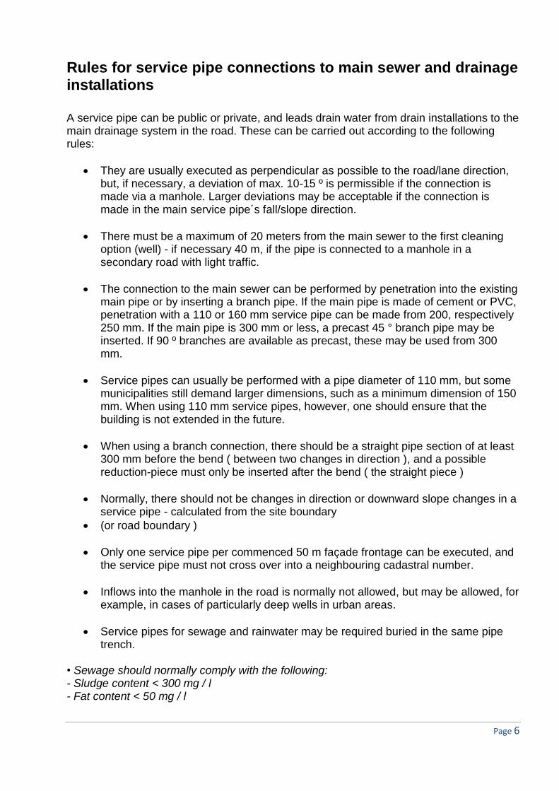
Class 4: Very permeable soil type, where the water table is occasionally or always above the drainage level, and where there, therefore, cannot or must not be drained..
Class 4: a. The water pressure
cannot be removed without great permanent drainage.
b. The construction is dimensioned for water pressure on the retaining wall and floor, and for buoyancy.
c. In cases where the calculated water pressure is exceeded, an inserted drain can be used.
For soil classes 3 and 4, the groundwater must often be lowered during the construction
period.
Very permeable soils are soils with a permeability coefficient k> 10-4 m/s, and soils with
low permeability are soils with k <10-5 m/s, but the situation must be assessed on a case
by case basis, taking consideration to, among other things, the ground water table level .
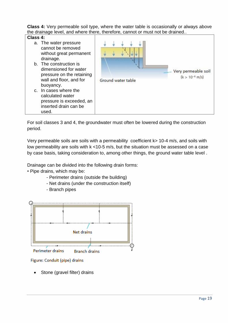
Drainage can be divided into the following drain forms:
• Pipe drains, which may be:
- Perimeter drains (outside the building)
- Net drains (under the construction itself)
- Branch pipes
Stone (gravel filter) drains

Page 20
Figure: Gravel filter drain, perimeter drain, branch pipe
Inserted drain.
Figure: inserted drain shown with washed gravel/stone (singles)
The drains are usually always led to a pump well, but pipe drainage can be directly
connected to the drainage installation if the connection level to the rest of the drainage
installation is:
Minimum 30 cm above the sewer flooding level
Minimum 30 cm above the top of the main conduit (measured inside)
Minimum 20 cm above bottom furrow level in the connection well (water table)
- If just one of the aforementioned conditions has not been met, the drain must be led to a
pump well.
Gravel filter drains and inserted drains must always be led to a pump well (if there is a risk
of odor and moisture occurrences underneath the building in cases of possible flooding
(damming) or blockage). Gravel drains can, in some special cases, be drained to
perimeter drains through a branch pipe.

Page 21
Drainage should always be passed through a sand trap, of min. 300 mm. before
connecting to the drainage installation, infiltration systems, or open recipient.
If the drain is led to an open recipient, the outlet must be placed above the highest expected water level (flood level) using a 30 cm safety margin. The outlet must be protected against frost! Drains, which must be min. 70 mm, must be laid with a slope of min. 3 ‰ and at frost-free depth, which is usually 0.75m - but 0.60m in heated buildings, and they must be placed minimum 30 cm below the structural member which is to be kept dry.
Figure 14, above: Perimeter drains. Surface water must be led away from the building
regardless of whether the building is executed with or without a basement. The terrain
must, therefore, slope away from the building for a distance of minimum 3 meters. For a
building with a basement, the slope must be 20 ‰ for soil and 15 ‰ for paving, or similar.
For buildings without a basement, half the slope can be used, i.e.,10 ‰ and 7 ‰,
respectively. The top of the backfill of trenches can be completed with minimum 0.2m.
“dense/”tight” soil, e.g., a clay-humus mixture. The figure, above, does not show all the
technical details regarding the DPC and internal insulation.
Drainage can be omitted if the floor level is more than 30 cm above the terrain level.

Page 22
Perimeter drains at basement walls The perimeter drain is placed at the foundation plinth, and is designed in the same way as
shown in Figure 14. The bottom furrow should not be placed higher than the bottom of the
anti-capillary layer below the basement floor and should also be a minimum of 300mm
below the basement floor.
Small light boxes (0.6 - 1.0 m2), and partly or wholly covered cellar stairwells can usually
be led to the drain system´s filter material through a column of stones/gravel.
Figure: drainage of light wells to perimeter drain through a filter column of nut-sized stones (singles) Permission, from the local municipality, for the connecting of the drain to the wastewater system cannot be expected. Where there is a risk of ochre precipitation, the drain connection to the gullies must be performed as lowered/sunken ones. This is because precipitation of ocher is minimized under low-oxygen conditions.
Cleaning access should be set up in selected break points, but with spacing of no more than 60 m. Drains are maintained 2 - 4 times the first year, then 1-2 times per year in subsequent years.
Drainage from special rooms
Refrigerator / freezer rooms, and boiler-rooms
Refuse bins /Refuse rooms Air raid shelters
Special measures are valid for the aforementioned rooms Refrigerator / freezer rooms

Page 23
The effluent is passed, via a drain (without water trap), to a min. 300 well with a sand trap and water trap, and with an inlet for other water source (rainwater or surface water, or non-odor producing sewage). If the floor drain is equipped with a water trap, this must be protected against freezing, e.g., by using antifreeze or by heating it, or by deep placement of the water trap itself. Rather than using a water trap, the room can be secured against odors using a hand-operated anti-flood valve or a closable drain.
Conditions for foundations, excavation and foundation conditions
Where small pipes are routed through a foundation, one must always make a recess for its
passage. The recess must be big enough to allow some form of settlement of the pipe or
the foundation. There must be 50-100 mm free space around the pipe, and the recess
must not be cast completely out with concrete.
If there is a demand for a tight feed-through of the pipe through the foundation, special
sealing sleeves should be used for flexible and rigid pipes. The seals should, in all cases,
ensure a flexibility that allows the pipe/foundation to settle without the pipe cracking,
breaking or deforming. If a pipe passes under the foundations, the edges of the foundation
surrounding the pipe must be carried down to disperse the pressure from the foundation
above away from the top of the pipe, as shown in the diagram below.
There may be risk of settlement or cracking when excavating, e.g., along the foundation

Page 24
For foundations, where the width exceeds 1 m (e.g., column foundations), a = 3 at a distance of up to 2 x b from the foundation. The rules apply to: • shored excavations in clay and sand • Open excavations in clay and sand
Figure: the placing of gully wells The formulas can be written as:
1. d = l/a 2. l = d x a
where d = depth, l = length and a = slope - But this can also be expressed with words:
1. Should extra foundation be executed? ”Within the first 2.0M of the length, divided by 3. The remainder of the length is divided by 1.5 ".
The height difference is added to excavation level, and the new soffit (lower edge) of the foundation is found.
2. How far must the pipe/well be moved?
Crossing point
Conc. floor
2 x b min 2.00 m a = 1.5
0.67
b a = 3

Page 25
"Within the first 0.67 m of depth, multiplied by 3. The remainder of the depth is multiplied by 1.5".
To the distance is added a half digging width/dig diameter, and the center of the pipe, respectively, the well, can then be found. The drawing shows a corner of a building and a longitudinal pipe with an associated manhole well. In order to do a calculation to ascertain whether the manhole well is positioned correctly in relation to the foundation, you will need:
1. the distance between well excavation and foundation = 2.25 m and 2. height difference between the bottom edge (soffit) of the foundation and
excavation´s bottom = 16.70 to 15.45 = 1.25 m
1. Should extra foundation be established?
The distance is 2.25 m the first 2.00 m / 3 = 0.67 m residual of 0.25 m / 1.5 = 0.17 m 0.84 m, which is added to the excavation soffit level i.e., 15.45 + 0.84 = 16.29 - this is the new soffit (lower edge) of the foundation. So, extra foundation of a total of 0.41 m (16.70 to 16.29) must be established. However, this can be an expensive option and one can instead examine:
2. How far should the manhole well be moved?
The difference in height is 1.25 m the first 0.67 m x 3 = 2.00 m residual 0,58 m x 1,5 = 0,87 m 2.87 m, which must be supplemented with a half digging diameter, i.e., 2.87 + 1.00 = 3.87 m, and the distance to the center of the well is found.
Dig diameter 2.00 m
BK 15.65 (15.45)
2.25 m FU 16.70
Manhole well 1 m

Page 26
If we have to choose the original location, i.e., to execute extra foundation, e.g., because of insufficient space to adjoining properties´ boundaries, how far out to the sides should we perform this additional foundation? We have figured out that if we remove the manhole well 3.87 m (the center of the well) from the foundation, we should not need to execute further foundation. In other words, if we maintain the original location, all foundations within a radius of 3.87 m need to be founded further to level 16.29. This applies only to small extra foundations. If deeper foundations than 60 cm are required, first subtract 60 cm of the height difference and then calculate how far out to the sides there needs to be extra foundation. Stepping-down of the foundation The “stepping-down” of the strip foundations can be implemented with a horizontal underside made in steps of a maximum of 0.6 meters, and a resulting foundation slope no steeper than 1.1. Compliance with this requirement has significance for buildings with partial basements. See Figure 9.
Figure 9. The soffit (underside) of foundations (foundation footings) must be horizontal and plane. The step-down of strip foundations must only happen in steps of max 0.6m, and with a slope, dependent on soil conditions, which must not be steeper than 1:1.
The laying of sewers The following requirements for both rigid and flexible pipes are valid:
• Sufficient strength to withstand the applied loads (traffic, soil, etc.)
• Adequate resistance to mechanical, chemical, thermal and biological impacts

Page 27
• Adequate period of function, i.e., durability.
Therefore, the materials for pipes, fittings, wells and individual connections must all be CE-
labeled. The CE-label cannot be regarded as a guarantee of quality. Even if a product is
CE-labeled, national building regulations may well exist, which means that the product can
be utilized only to a limited extent in a country.
Take into account the DS 455,”The standard for density of drainage systems in the ground
", and DS 421,” The standard for tight flexible joints in pipes of concrete, etc.”
DS 475,”Standard for the establishment of distribution systems in the ground”, subdivides
the laying of, among other things, sewers in soil into three project categories :
• Eased project category
• Normal project category
• Tightened project category,
where the definition of the project category is based on the difficulty of the project , for
example, less favorable soil conditions.
The standard also differentiates between three safety classes:
• Low safety class
• Normal safety class
• High safety class,
which are determined by the consequences that may arise from any failures, for example,
leaks during both construction and operation.
In DS 430, " The standard for laying of flexible pipes made of plastics in soil", and DS 437,
" The standard for laying rigid pipes of concrete , etc., in soil " establishes the control level
, notably based on laying conditions and the wastewater´s content , as well as the
influences pipes are exposed to.
These control levels are:
• Tighter controls
• Normal control
• Relaxed inspection,
and may include the following :
• Course of the pipes and its levels
• Pipes, wells parts and assembly materials
• Excavation, laying and backfilling
• Density (tightness), final control/inspection,
or other checks/inspection specified in the project .

Page 28
The laying of flexible drainage and sewer pipes
DS 430,”The standard for laying of flexible pipes made of plastics in soil" refers to pipes of,
among other things, PVC, PEH and stainless steel, and is usually laid on a levelled layer
that is minimum 100 mm. With smaller dimensions, for example, 110 mm or less, and if the
base is leveled off, the layer thickness is reduced to 50 mm.
In unpaved areas, the requirements for levelling layer and perimeter back-filling:
• Grain size max. 16 mm
• Grain sizes 8 - 16 mm, must max. comprise 10%
• The material must not be frozen,
and materials for the levelling layer should not be sharp flint or similar .
For the surround-filling, one can use other materials, e.g., clay - if it can be compressed
efficiently.
In paved areas, the requirements for the levelling layer and the perimeter back-filling:
- Grain size max. 8 mm
- The content of grains under 0,075 mm may max. constitute 9%
- The material must not be frozen, or contain harmful plant residues, humus, clay or lumps
of silt, and must not be harmful to the pipe or pipeline.
Furthermore, the surrounding backfill material should have a uniformity coefficient , U, of
less than 3.
Compacting must be implemented in layers of max. 30 cm., and up to 10 cm above the top
of the pipe, but never just above the pipe.
Soil cover must not exceed 6 m, and minimum 1 m where there is traffic over the pipes. If
this is exceeded, calculations must be made that proves that the pipes can withstand the
loads they are subjected to!
The term uniformity coefficient , U, refers to a grain diameter for a 60% through-fall divided
by the grain diameter, which corresponds to 10% through-fall.
Municipal information In order to design and execute a drainage project, it is often necessary to obtain a variety
of information, either from the owner of the property (the builder) or from the local
authority.

Page 29
The list below shows a summary of the most common queries a municipality's technical
administration may encounter:
In accordance with which principle is the sewage system established? - (separate, combined system or other?)
the location and course of the main sewer, including pipe material, pipe dimensions, levels (depths), pipe slopes and fall direction , possible manholes and wells.
a) Cover levels, road levels and other terrain levels (current and/or future)
Is the area furnished with a sewer system at all, or expected to be developed with one in the near future?
Can and may the area be furnished with seepage installations, including biological sand filters, gravel filters, small treatment installations, or possibly, a root zone or willow system, with or without a solid bottom?
Must already completed connections or service pipes be used, and will the Technical Administration of the municipality perform the service pipes?
Have connections to street drains or pipes leading up to the property been made? - If so, information must be furnished on the location and course of these installations, and their materials, dimensions, levels and slope, etc.
Can damming (flooding) in street drains be expected, and at what elevation?
How secure is the information about the damming? Is this established on the basis of measurement or calculation? Are the given levels including a 30 cm safety margin?
Is the site's terrain low, for example, relative to the road? - (the damming (flooding) risk is thoroughly assessed).
If connections or service pipes are not provided, are there demands for specific connection-locations (wells) for these, or can these be set freely?
Can more connections be made than are normally occurring?
Can pipes, wells or other installations be placed outside building boundary? - (apart from the service pipes)
Can a manhole well be connected to the street sewer, and under what conditions?
When connecting to a manhole in the street, is it allowed to connect a service pipe, which is not performed perpendicular to the street lane direction?
What is the nature of the pavement adjacent to the property, and will the municipality´s technical administration perform the re-establishment of the pavement?
Is there a building boundary or longitudinal pipes, or possibly other service connections? - (TV, gas, water, telephone, heating, electricity, etc.)
Are there special requirements for shut-off installations, to workmanship, to the relationship to traffic, or other special circumstances that may require the work done at night?
Are soil and groundwater levels known in the area?
Where is the nearest cadastral fixed point (level or plan fixed point), and what is the level?
Can rainwater be led to an Infiltration trench, and what is the rain intensity?
Can the street connection be possibly performed as s 110 PVC, or should it be minimum 160?
Must venting the system be established above the roof?
Must the common system be performed so that it can subsequently be conversion into a separate system?
Is there an average drainage coefficient for the property/plot?

Page 30
Is there a connection fee, service pipe connection fee, payment of a service pipe, or invoice or sewer contribution?
Must the final drawings be furnished with relative levels and elevations, or should it be furnished with elevations/levels in accordance with DVR?
Are there easements, local structure plans or other conditions imposed on the property, which may affect the course of the piping, or possibly, the choice of materials?
Is a listed forest or possibly listed trees on the plot/property?
Can some of the road space be used for storage space for excavated soil, building materials, or possibly portable cabins and sheds?
On the basis of the above information, a sewer and drainage project can be compiled so
that it can form the basis for the municipality´s approval, and can provide the necessary
building permit.

Page 31
Did you remember that? A drawing should be as thorough and complete as possible. Therefore, it is important to
remember such things as:
Dimensions and materials on manhole wells, flushing wells, roof gulley (wells),
pump wells, surface wells, etc.
Cover levels, bottom furrow levels (water levels) connection levels to all wells
Frost-free depth (0.75 m below ground level), for example, sand trap wells,
roof gullies, etc.
Dimension and bottom level of floor drains (100 ga, also in light boxes)
Water traps in floor drains, roof gullies, surface wells
Slope in ‰, material and dimension of service pipes
Bottom level and connection level for the connection level for the service pipe
in the road.
Possible reduction section 110/160 with the correct signature (two lines and
text)
Rainwater pipes must be laid with 20 ‰ before and 10 ‰ after sand traps
Draw-in the bottom furrow (flow) in manholes and flush wells (not in sand
traps)
Stop and start level of pump wells
Pumping capacity in l / s
Pump storage in liters or m3
Anti-flooding closer, for example, ”HL ", " TH "
Necessary levels and cross-hatching of foundation stepping-down
Levels at crossing lines
Dimensions of drains (e.g., 70 PVC, 3 ‰ and fall direction with arrow)
Difference in in- and outlet at dimension changes, for example, at branches
and reduction fittings
Difference in in- and outlet at sample wells, for example, 20 - 30 cm
Difference in in- and outlet in fat, oil and petrol separators, septic tanks and
acid neutralizers.
Similarly, a drawing must be easy to "read" and manageable. Therefore, repetition on
drawings should be avoided. Instead, these should be specified in the drawing´s notes.
Among other things:

Page 32
Note: on the floor/situation plan
• All undefined pipes are 110 PVC
• All undefined flush wells are 315 PVC
• Unnamed roof gullies are, for example, 200 PVC 300 bt or 315 PVC
• All undefined sand trap wells are 315 PVC
• All wells are completed at terrain level
• All undefined sewers are located with the given slope, min. 20 ‰.
• All undefined rainwater pipes are located with the given slope, min.10 ‰.
•”Dry" rainwater piping is laid with a slope of min. 20 ‰.
• All floor drains are GA 100 mm.
• Bottom level in un-named rest bends for wastewater (sewers) is: 34.18
• Bottom level in un-named rest bends for rainwater is: 34.28
• Foundation reinforcements are illustrated on drawings excluding stepping-down, and
constructed to DS 415
• Floor drains, which are seldom used, are refilled every 14 days
• Pumps are equipped with auto start and stop, and non-return valves.

Page 33
Oil and petrol (fuel) separators
Oil or petrol separators are required where there is a risk of spillage of oil or fuel, for example, at:
• Filling stations and places of sales
• Washing and "do it yourself" areas
• Workshops, lubricant and car wash areas.
Fuel/petrol separators are only established at drains where there is a daily risk of spillage of fuel during normal operations.
Sketch in principle
For the above, certain special provisions must be observed!

Page 34
Grease and fat separators Grease and fat separators should be placed where, in normal operation circumstances, grease and fat may occur in the drain water, or grease spills may occur on the floor, for example, because of: • Large kitchens, takeaways, catering businesses • Food production • Hotel and restaurant kitchens • Barracks and other institutions • Slaughterhouses, etc. For the above, there are specific measures which must be observed!
Pump wells Pump wells are generally placed in the open, but can be placed in the building. Pump
wells are performed with dense, tight cast iron covers, perhaps ones that are fixed, and
must be readily available for inspection, cleaning, maintenance, and possible repair.
The pump systems should be equipped with an alarm if a potential pump failure could
result in flooding, downtime or other adverse effects.
Pump wells should be equipped with automatic start and stop, and the water amount,
which is in between, depends on factors such of the volume of water, pump capacity ,
number of starts per hour per day , etc. ( guidance in DS 432 : min. 10-15 minutes
continuous supply of q S,d), or pump´s performance for 2 - 3 minutes.
The start level is usually 10 - 20 cm below the connection level for the inlet. The stopping
level is usually approx. 20 cm above the pump´s suction pipe.
Pumping of wastewater can usually be divided into the following categories:
• Drainage water
• Wastewater without toilet and urinals
• Wastewater with toilet and urinals (all wastewater).
Pumping of drains covers all types of drains, small amounts of rainwater, for example,
basement stairwells and light boxes and small, non-odorous sewage quantities, for
example, boiler room and other seldom used floor drains.

Page 35
In a separate system, the water is always pumped to the rainwater system where the
pump pipe can be led to:
• Gullies of min. 300 mm
• Manhole wells or cleaning wells
• Open pipes in pump wells, min. 30 cm above the damming/ flooding level
• Internal drain installations, for example, a ventilated pipe.
Drain pump wells do not necessarily need to be ventilated, and can be performed with a
flat bottom. If any sand occurs in the drainage water, the bottom should be executed with
sloping sides and the slope must be towards the pump.
The pumping of wastewater without toilet and urinal also includes small amounts of
rainwater, for example, from cellar stairwells and light boxes. Drains must not be
connected to the pump wells.
100 ga 100 ga
315 pvc
PEL – pressure pipe (35 - 50 mm)
auto. pb. 0.6 – 1.0 m (in-situ)
100 ga e.g., boiler-room/installations room
PEL – pressure pipe(40 - 75 mm)
auto. pb 1 m (in-situ) . kv
100 ga 50 mm vent.pipe

Page 36
In a separate system, water is always pumped to the wastewater system where the pump´s pipe can be led to: • Drainage gullies, min. 300 mm without inlets from kitchens • Manhole wells or cleaning wells • Open pipes in pump wells, min. 30 cm above the damming/ flooding level • Internal drain installations, for example, a ventilated pipe. Well bottoms are performed with sloping sides and the main slope towards the pump. The pumping of sewage with toilet and urinal also includes small amounts of rainwater, for example, from basement stairwells and light boxes. Drains must not be connected to the pump well. In a separate system, water is always pumped to the wastewater system where the pump
pipe can be led to:
• Manhole wells or cleaning wells • Open pipes in pump wells, min. 30 cm above the damming/ flooding level • Internal drain installation, for example, a ventilated pipe.
Sewage pump wells must be ventilated, preferably immediately just under the cover, and
wells that pump sewage containing faeces must also have minimum 1 inlet led to the
outside.
The well bottom must be performed with sloping sides, with the main pipe sloping towards
the pump so that all possible impurities are pumped away.
PEL-pressure pipe (75-100 mm)
auto. pb 1.25 m (in-situ)
kv
wc
ot
100 ga
315 pvc
50 mm vent.pipe

Page 37
Anti-flooding sewer and drainage devices
Damming or flooding in the main sewer system can occur if the pipeline system is, for
example, undersized, blocked, or because of pump failure, or because of high tide in the
recipient. This can be especially bad during heavy rains, and to prevent water from
entering the basement through, for example floor drains, an anti-flood valve can be
installed in the floor drain.
Anti-flooding devices such as an anti-flood valves may be used as protection against
flooding of rooms and areas during the damming of drain installations, for example, during
the damming in the main drain pipe. Anti-flooding devices must be CE marked.
The standard DS 432 4, Edition 2009, which is called "Code of practice for drainage
systems”, defines an anti-flood valves as: A device that can be closed manually and
automatically, so that no water can flow into the drain installation or building on top of
backflow blocker.
The European standard for anti-flood valve, DS / EN 13564, stipulates that there are 6
different types of backflow valves, which can be CE-labelled.
Type Use Arrangement Use in Denmark
Type 0
On horizontal pipes
Only 1 auto close valve
Type 1
On horizontal pipes
Only 1 auto close valve, which is also forced closure
Type 2
On horizontal pipes
2 auto close valves, one is forced closure
used for non-faeces containing sewage
Type 3
On horizontal pipes
2 auto close valves, one of which is electric, or similar
used for faeces containing sewage
Type 4
For floor drains
only 1 auto close valve, which is also forced closure
Type 5
For floor drains
2 auto close valves, one is forced closure
used for non-faeces containing sewage

Page 38
The above table shows that only 3 types of closer valves (Type 2, 3, and 5) can be used in
Denmark. This is because, as mentioned above, that a backflow closer valve must have 2
closers, operating independently of each other, and one of which must be forced closed.
Types 0, 1 and 4 can, therefore, not be used in Denmark since they only have one close.
Anti-flooding (backflow closer valves) devices must be supplied with the manufacturer's
illustrated instructions for installation, operation, maintenance and testing for leaks on site,
as well as having a clear and durable marking label, for example, as molded, stamped, or
labelled.
Anti-flooding devices (backflow closer valves) (type 3) may only be installed on pipes
carrying faeces-containing sewage when there is adequate security against flooding at the
inlet side. Reassuring security can be expected when the user community is small, for
example, in single-family houses, and there is at least a toilet over the highest damming
level, and this toilet is not connected to a backflow closer valve. Furthermore, it is stated in
DS / EN 13564 that backflow closer valves for wastewater containing faecal matter must
be equipped with a visual and audible alarm. Anti-flooding devices (backflow closer valves)
must be located so that they are easily accessible for operation, inspection, cleaning and
maintenance, and the operating instructions for the backflow blocker valve must appear on
a sign or the like, which is visible from the place of operation.
Anti-flooding devices should only be fed by inlets that are placed below the water table during damming, and must be located as near as possible to the installation object.
Rain or drainage water should not be led behind a backflow blocker valve or backflow
stop. Rainwater from smaller areas, e.g. basement stairwells, can however, be led to a
backflow blocker valve, as the rainwater quantity here is not very great. However, it is
important to ensure that any flood does not result in damage in, e.g., low-lying spaces.
Placing a backflow blocker valve on a service pipe should be avoided (requires an exemption from the municipality – but there is no operational problems with this solution).
The municipality must notify about the damming level, and a safety height of 30 cm must be added to this.
A toilet can be mounted with a backflow blocker valve (type 3) , but instead of a backflow
blocker, one can, where the basement height is reasonable, raise the toilet so that the top
edge of the toilet bowl becomes equal to the damming level including the safety margin of
30 cm ( previously called a " throne "). A better solution would probably be to raise the
floor of the cubicle with a step outside the toilet door. The washbasin in the toilet room
should not be led to a floor drain, which is connected to a backflow blocker valve, but

Page 39
should be performed with independent water trap, so the washbasin can be used even
when there is standing water in the floor drain.
If several floor drains have been installed/connected to a backflow blocker valve, one must
be aware that during use, flooding can happen from one room to another through the pipe.
The backflow blocker valve should possibly be able to close the valve in the same room.
A backflow blocker valve requires supervision. Therefore, e.g., light boxes with limited
access should not be connected to a backflow blocker valve.

Page 40
Acid neutralizers
If is a small risk of acid residues in the drain water, a container must be provided, which is equipped in such a way that the acid is neutralized. This can be done with all basic materials, such as chalk, limestone, marble, slaked lime, and sodium hydroxide.
In the above, there are specific measures and provisions which must be observed!
Rainwater Systems
The use of rainwater for toilet flushing and washing machines have for years been a major desire, for among other reasons, to reduce the consumption of groundwater resources and especially to promote environmental awareness.
Rainwater is directed from roofs, through gutters and downpipes, down into a storage tank located in the building or buried in the ground. To remove leaves and other impurities, a filter is placed in the downpipe.
From the storage tank, the rainwater is pumped to the installations that might use it – i.e., the WC and washing machine. A floating filter is fixed on the suction pipe side of the tank, ensuring that the floating debris in the tank does not enter the installation.
The temperature in the storage tank must be kept as low as possible (not more than 18 ° C) to limit bacterial growth.
There must be an overflow from the storage tank, and the system must be designed so that there is overflow 3-5 times a year. The overflow must be placed at the top of the tank and be designed so that the floating debris is removed by overflow.
The overflow can be led to the ordinary public sewer installations, or can be led to seepage trenches (Infiltration trench) via sand traps.
In dry periods, it may be necessary to supplement the tank with ordinary tap water (drinking water). It is an important requirement that the installation is designed so that rainwater in the tank, under these conditions, does not contaminate drinking water supplies.
Rainwater is not drinking water. It is therefore important that an outer spigot (tap) for, e.g. car washing or watering the garden, is established with caution. Small children might mistakenly drink of the water.
Not all roof surfaces/paving and cladding are suitable for collecting rainwater from. Therefore, roofs with the following materials and unsuitable for rainwater collection:
• Roofs clad with new bitumen will often discolor (yellow) the rainwater and, therefore, may be unsuitable for laundry.
• Grass, moss and thatch roofs will reduce the rainwater volume significantly, and constitutes a risk of discoloration.
• Copper roofs and copper gutters.

Page 41
• Asbestos-containing roofing.
It is not always possible to include the whole of the total roof area for rainwater collection. Different roofing materials have different degrees of water run-off. In average, the run-off rate is set at 0.75, which means that 25 % of the rainwater cannot be collected (evaporates or just pools/collects).
It should be noted that the greater the slope of the roof, the greater the run-off rate.
When sizing a rainwater system, there are various factors that influence the tank size, for example:
• number of WCs
• number of washing machines
• roof area
• annual average rainfall
A rule-of-thumb states that a detached house of 250 m2, with 2 adults and 2 children, and with installations comprising 2 pcs. WCs and 1 washing machine, will be sufficiently supplied with an underground tank of 3.5 m3, and will achieve satisfactory results.
The risk of infection by using rainwater is considered to be small. There may be some fecal contamination, for example, from bird droppings, but the risk of infection can be minimized by regular hygiene.
Rainwater systems should not be established for facilities and institutions with specific vulnerable groups - for example, hospitals, retirement homes and child care centers.
The nationwide consumption of water for toilet flushing and washing machine represents approx. 30%.
CE - approved parts must be used for a rainwater system. This includes pipes, filters, pumps, storage tanks, etc.
As a rule, an application for planning permission must be sent to the local council in order to establish a rainwater system. This does, however, not apply to existing single-family homes, townhouses, cluster houses, “close-low" developments, etc. These are subject to the building regulations.
A building permit will be probably contain demands for the project.
Local drainage / use (LDR)
Climate change and increased rainfall makes it attractive to try to deal with rainwater where it falls, so that it does not burden the municipal drainage system. Managing

Page 42
rainwater as close to the source as possible is sometimes referred to as the LDR - Local Drainage of Rainwater.
What is LDR?
Local rainwater drainage means any action that is intended to limit or delay the flow of rainwater from an area. Typical elements are:
• Soaking / infiltration from surfaces or through permeable surfaces, or infiltration sinto trenches.
• Delay of the water as widely as possible
• Collation of water in ditches and depressions in the ground, or in dedicated ponds
• Evaporation of water from either from the surface or through inclusion in plants and shrubs.
The different methods can be divided as follows:
• Management at the source (inlet / intake)
• Evaporation / soaking down / delay
• Only delay / evaporation
Handling at the source: Green roofs, infiltration trenches, collecting in barrels, use of rainwater for toilet flushing.
Evaporation/ percolation (soaking down) / delay: Green areas, troughs, ditches, permeable surfaces, , infiltration basins, wet basins / ponds, wetlands.
Only delay / evaporation: Traditional open basins, expanded basins.
Drainage options
Drainage of domestic sewage can be led to:
• public sewers (or private), and on to treatment plants and recipient
• seepage through a settling tank
• collecting tank with municipal collection scheme
• willow treatment plants via a settling tank
• mini treatment plants via settling tank
Roof water and surface water can be led to :
• public sewers ( and private)

Page 43
• seepage via sand traps (infiltration trenches )
• discharge to streams, lakes, the sea, ( field drains ) via sand traps
Infiltration (seepage) of rainwater
An infiltration trench is a soak away, which is designed to receive rainwater. The infiltration trench’s size should be dimensioned based on the volume of water to be infiltrated and soil´s characteristics, i.e., the soil's ability to drain and clean the water. The infiltration trench must be large enough to receive a 10-minute rainfall where the rain intensity = 140 l/s/ha (i.e., n = ½). The rain intensity may be expressed in l/s/m2.
It is only the part of the infiltration trench, which is above the groundwater table or under a possible perimeter drain that can be attributed to the effective volume.
An infiltration trench can be executed with the pebble-sized stones, or plastic trays with lightweight aggregate (LECA) in bags (infiltration trench bags) as a filler.
An infiltration trench´s normal dimension should be (drawing in section):
Terrain 0.5 m Tight cover 0.5 m2 1.0 m 0.5 m The infiltration trench should be as narrow and elongated as possible as it provides the
largest soak away area against the ground.
An infiltration trench is filled with stone, for example, so-called shingles1 (32/64 mm), which
provides a void of 25%.
The infiltration tranche’s volume for q R, d = Fr x 140/10.000 x 60 x 10 x 100/25 litres (can
be expressed in m3 by dividing by 1000).
The infiltration tranche’s length is found by dividing the ascertained volume with the
tranche’s cross-sectional area (usually 0.5 m2).
1 Singles is a Danish word for pebble sized stones of a certain size

Page 44
n Design storm
intensity
l/sxm2
usage
Seperat systems Combined systems
1 0,011
Where there is a risk of
disadvantages, for example.
minor flooding outside the
buildings
Where there is a risk of
disadvantages, for
example. odor. Floods are
not accepted
½ 0,014
Where there is a risk of easily reparable damage to buildings
fixtures and the like. Damages should be created for general
cleaning and drying out briefly. Should occur only flood the
space with waterproof floor constructions
1/10 0,023
Where there is a risk of severe reparable damage to buildings,
equipment, etc.
0 Where there is a risk of accidents and health hazard to animals
and humans
n is the annual probability of the occurrence of rainfall at an intensity that is greater than
the design level intensity.
The listed rain intensities correspond to national rain downpours with a duration of 10
minutes, in accordance with the Wastewater Committee´s Publication No. 16. Local
authorities may prescribe other rain intensities based on local statistics.
If one is to take into account the expected future climate changes, rainfall intensities can
be multiplied by the following factors, which are calculated for the projected horizon/
expected technical lifetime of 100 years.
Rain repetition period 2 years 10 years 100 years
N 1/2 ¼ 1/100
Climate factor 1,2 1,3 1,4
An infiltration tranche’s volume can be set to 1 m3 trench/30 m2 rain area. However, this
requires that the rain intensity = 140 l/s/ha, void ratio is 25% and φ = 1.0
Infiltration trenches can be made smaller in sandy soils. An infiltration tranch should not be
less than 0.5 m3.
Instead of a stone material, infiltration trenches can be built of rainwater trays (or cassettes
of plastic), and here the void ratio is about 96%, or of lightweight aggregate (expanded
clay granules) that come in bags, with a void ration of approx. 50%. By using rainwater
cassettes or infiltration bags, the dimensioning can be done in the same way or in
accordance with the manufacturer´s instructions.
The above methods are only indicative as the sizes of infiltration trenches are greatly
dependent on soil conditions. That is, the soil's ability to drain water. In these cases, count
on normal soil conditions.

Page 45
After some time, the bottom of the infiltration trenches can sometimes become clogged
with sediment and sludge, so seeping of water will only happen through the sides of the
trench.
The municipality may authorize the construction of infiltration trenches when the following
distances are met:
• 5 meters from residential areas and buildings with basements
• 2 meters from other buildings
• 2 m from the property boundary
• 25 meters from drinking water wells
• 25 m from streams, lakes, and the sea.
In addition to the above mandatory distances, an infiltration trench must observe the
recommended distances below:
• 2 m between infiltration trenches
• 5 m from the lake, sea, stream (according to § 14 - combined discharge and seepage
authorization)
In addition, surface run-off or other nuisances must not occur. If a municipality is the
approval authority, infiltration trenches must not receive water from public roads, railways
or from parking lots for more than 20 cars. Infiltration trenches must not be shared with
house or industrial wastewater.
A property owner may be given permission to establish an infiltration trench himself to lead
water from his downpipes. It must be on their own property and be constructed in
accordance with current regulations.
Drainage from cellar stairwells, light boxes, driveways and the like should, because of the
risk of flooding, be led to separate infiltration trenches.

Page 46
Holding tanks The establishment of holding tanks for domestic sewage and surface run-off from two
households is approved by the local council, and the tank may be:

Page 47
Dimensioning according to the norm The dimensioning of a drain pipe means that the correct size and the correct slope are
found on the basis of a specific drain water intensity, so that the drain is self-cleansing.
That is to say that there is a reasonable assurance that the following will not occur:
• floods
• odors
• deposits
• noise problems
Dimensioning, or sizing, is done in accordance with DS 432.4, "Standard for drainage
systems", and can be accomplished in one of the following ways:
• The standard´s annex (Civil Engineering)
• The standard´s diagrams ("complete calculation")
• The standard´s guidance (10 ‰ - 20 ‰).
Definitions: q = drain water flow q S, d = designed wastewater flow qR, d = designed rainwater flow qD, d = designed drainage water flow qP, d = designed pump water flow q S, f = projected wastewater flow qf = water flow capacity Imins = minimum slope for wastewater Iminr = minimum slope for rainwater I = the rain intensity (l/s/ha) φ = drainage coefficient (factor 0.0 to 1.0) Fr = the reduced surface area (m2 - area x φ) n = the annual probability of the occurrence of rainfall at an intensity that is greater than the designed intensity. Coupling pipes lead discharge from only one installation items or 1 rainwater inlet. Collecting pipes lead discharge from multiple installation items or several rainwater inlets.

Page 48
The projected wastewater flow
The projected wastewater flow, qS,f is found in the norms section on sizing, or in the CE-
approval sheets for each individual installation item.
The most important here is given in l/s:
Table 3.10.1 – Dimensioning of non-ventilated sewage pipes
Sum of projected sewage water flows2
Smallest internal diameter3
di
mm
0.3
0.6
1.2
2.4
2.9
3.9
5.4
8.5
12.6
26
34
44
56
65
804
96
115
145
Do not interpolate in Table 3.10.1
Washbasins in toilets or anterooms to rooms with WC are not included in the sum of the
projected wastewater flows
The projected wastewater flows are included only for installation items with individual
water traps.
In the case of floor drains, the projected wastewater flow, q S,f, is usually determined by
reference to the number of installation items that are connected and designed for use at
the same time - i.e., for one or two installation items, select the largest anticipated value.
But for three or more, select the two largest drainage flows.
2 In case of sewage pipes that only lead sewage from one room, the designed sewage flow is used in accordance with
3.2.2.2
3 See the limitations under 3.8.3, 3.10.3, and 3.10.4 for all dimensions
4 If a pipe is connected to a WC, other installation items must not be connected.

Page 49
For hosing-down floors in dwellings, the projected wastewater stream/flow is set to 0.4 l/s,
and this will usually not happen while any other installation items are being used. In non-
residential buildings, however, drainage streams/flows are set in each individual case.
If the projected wastewater flow for floor drains cannot be determined from the above, it is
set to 0.9 l / s for residential buildings, and 1.5 l / s non-residential buildings.
For showers with the pump drains, the projected wastewater flow, qS,f, is equal to the
pump performance , but minimum 0.4 l/s
For other pump systems, the projected wastewater flow can be set equal to the pump
performance.
The designed wastewater flow For pipes that carry wastewater from all rooms in one dwelling, the designed wastewater
flow, qS,d, is set to 1.8 l/s if the projected wastewater flow, qS,f, is less than 12 l/s.
The designed wastewater flow, qS,d, can never be less than the maximum projected
wastewater flow qS,f..
The designed wastewater flow, qS,d, will, for a connection pipe, always be equal to the
projected wastewater flow qS,f.
Design of ventilated wastewater pipes and rainwater pipes
Vents may be: • pipes led above the roof • cleaning wells • manhole wells • vacuum valves. Filling ratio: 0.5 - and max. 0.2 for stacks (vertical pipes). For separate systems, the filling ratios are: a. rainwater, always 1.0 b. wastewater (sewage), normally 0.5
1,0 1,0
0,7 0,5 150/160
ot
t

Page 50
Design of non-ventilated wastewater pipes No filling ratios. The design is based on experience and rules-of-thumb. The rules are the same for horizontal and vertical pipes, and it is important to know which installation items are connected to the pipe continuation up in the building because:
Table 3.10.1 – Design of non-ventilated wastewater pipes
Sum of projected sewage water flows5
Smallest internal diameter6 di
mm
0.3 0.6 1.2 2.4 2.9 3.9 5.4 8.5 12.6
26 34 44 56 65 807 96 115 145
Do not interpolate in Table 3.10.1 Washbasins in toilets or anterooms to rooms with one WC are not included in the sum of the projected wastewater flows
The “per thousand” slope (‰)l is the same as for vented wastewater piping. This means
that the installation item, which has the largest projected wastewater flow, is decisive for
the slope, as for a vented wastewater pipe.
The fall-height for a non-vented wastewater pipe must be a maximum of 6 m (bk - tk), but if
a pipe carries wastewater from the WC (max.1), the fall-height is, however, only 4 m. In
addition, pipes can carry wastewater from, e.g., I floor drain with the inlet flow of max. 1.2
l/s, provided that it is wastewater.
Design of rainwater pipes The filling ratio is always 1.0 for horizontal pipes, and normally 0.33 for stacks (vertical, or
standing pipes).
5 In case of sewage pipes that only lead sewage from one room, the designed sewage flow is used in accordance with
3.2.2.2
6 See the limitations under 3.8.3, 3.10.3, and 3.10.4 for all dimensions
7 If a pipe is connected to a WC, other installation items must not be connected.

Page 51
qR,d = A x φ x i
A = rainfall receiving area in m2 or hectares (10,000 m2), which is calculated as the sum
of:
- the horizontal areas
- the horizontal projection of the inclined surfaces, and
- 1/3 of the vertical surfaces, which are hit by the greatest driving rainfall, which are
usually the surface areas facing the prevailing wind direction.
φ = drainage coefficient is a factor with values from 0.0 to 1.0, for example:
1.0 = tight paving and surfaces
0.8 = paved areas with gravel /grass joints
0.6 = paved areas with gravel
0.1 = garden and park areas with drainage.
i = rainfall intensity in l/s/ha or l/s/m2, for example:
110 l/s/ha (n = 1/1)
140 l/s/ha (n = 1/2)
230 l/s/ha (n = 1/10).
If you need to take into account projected future climate changes, the rainfall intensity can
be multiplied by one of the following climatic factors:
Rain repetition period 2 years 10 years 100 years
n 1/2 1/10 1/100
Climate factor 1,2 1,3 1,4
The values are calculated for an expected technical lifetime (projection horizon) of 100 years. The climate factor should only be used when there is expressly set forth requirements that expected future climate change must be taken into account. In this situation, the pipe must be ensured adequate slope and a sufficiently large pipe dimension. Therefore, the climate factor should not be used when determining the pipe´s slope. When determining the pipe´s size, however, the climate factor should be taken into account. Supplement for driving rain: For exposed or free lying west-facing facades, the rain area is supplemented with 1/3 of the facade area under the premise that the rainwater from the facade is collected, for example, in surface wells. In some cases, one should also take into account the driving rain on shed roofs, canopies, covered balconies, covered petrol sales plazas, or similar. As for the exposed facades, it is also a prerequisite here that driving rain is collected. If the entire ground area is paved with asphalt, the above supplements for driving rain are omitted.

Page 52
"Dangerous" areas. For non-covered terraces or balconies in apartment buildings, ramps leading down to basements, or other exposed locations where there is a risk of flooding, i = 230 l/s/ha (n = 1 /10).
Procedure for dimensioning when using the norm´s diagrams Rainwater
The design rainwater flows (qR ,d) is calculated by using A x φ x i , or area x drainage
coefficient x rain intensity.
Remember the supplement for driving rain (west-facing facades) or ”dangerous” areas
(such as ramps down to basements), or the supplement for climate factor (“monster rain”).
The minimum pipe slope for self-cleaning ( Imin. ) can be read from the diagram for filled
pipes (filling 1.0 ) for rough and smooth pipes, respectively.
Per thousand slope (‰) and dimension is selected (always 1.0 filling).
(Small dimension - large ‰, larger dimension – small ‰) .
Water flow capacity ( qf ) is read from the selected combination of slope and dimension.
Remember that:
qf ≥ qR d, and Ichosen ≥ Imin
Wastewater (sewage), ventilated pipes The sum of the projected wastewater flows ( qs,f ) is added up.
The design wastewater flow (qs,d) is found using the concurrency chart.
Minimum slope for self-cleaning ( Imin.) is read from the diagram for half-filled pipes (filling
0.5 ) for, respectively, rough and smooth pipes.
The ‰ slope and dimension is chosen, the filling ratio is usually 0.5
(small dimension - large ‰ slope, larger dimension - small ‰ slope ) .
Water flow capacity (qf) is read for the selected combination of slope and dimension.
Remember that: qf ≥ qS,d og Ivalgt ≥ Imin

Page 53
Above: Figure 3.8.2b – Dimensioning diagram for ventilated sewage pipes made in plastic and stainless-steel
Wastewater (sewage), non-ventilated pipes Dimension: The sum of the projected wastewater flows (qS,f) is added together and must not exceed 5.4 l/s for 110 mm, and 12.6 l/s for 160 mm. ‰ Slope: As for vented wastewater piping (see explanation in Fig. 3.8.2 b above)
Water flow intensity in l/s
Min. slope in 0/00 for
self-cleansing
Minimum pipe
dimension for self-
cleansing.