guidelines for ammonia refrigeration plant equipment integrity … · 2019-12-17 · refrigeration...
TRANSCRIPT

FINAL DRAFT Dec. 6, 2019
Guidelines for Ammonia Refrigeration Plant Equipment Integrity Programs

DRAFT Final
Dec. 6, 2019
MAN-xxxxxxxx Page 1 of 157
1 Table of Contents
1 Introduction .............................................................................................................. 3
2 Purpose .................................................................................................................... 3
3 Scope ....................................................................................................................... 4
4 Definitions ................................................................................................................ 4
5 Owners Responsibility .............................................................................................. 7
6 Equipment Integrity Management Program Requirements ...................................... 8
6.1 Overview ............................................................................................................ 8
6.2 End of life determination .................................................................................... 8
6.3 Equipment integrity management program development ................................. 10
6.4 Use of contractors ............................................................................................ 10
6.5 Developing and documenting equipment integrity management programs ...... 10
6.6 Elements of equipment integrity management programs ................................. 11
6.6.1 Title Page ............................................................................................... 11
6.6.2 Contents Page........................................................................................ 11
6.6.3 Definitions and abbreviations ................................................................. 11
6.6.4 Scope ..................................................................................................... 11
6.6.5 Statement of Authority and Responsibility .............................................. 12
6.6.6 Manual Control ....................................................................................... 12
6.6.7 Organization ........................................................................................... 12
6.6.8 Training and Competency ...................................................................... 14
6.6.9 Document and Records Administration .................................................. 15
6.6.10 Procedures ............................................................................................. 16
6.6.10.1 Normal Operation ................................................................................... 16
6.6.10.2 Emergency Operation ............................................................................ 17
6.6.10.3 Inspection and Monitoring ...................................................................... 19
6.6.10.4 Maintenance ........................................................................................... 21
6.6.11 Installation, Repair and Alteration Methods ............................................ 22
6.6.12 Materials ................................................................................................. 23
6.6.13 Incident and Near-miss Investigation ..................................................... 23

DRAFT Final
Dec. 6, 2019
MAN-xxxxxxxx Page 2 of 157
6.6.14 Exhibits ................................................................................................... 24
6.6.15 Change Management ............................................................................. 24
6.6.16 Internal Audits and Control of Program Non-conformances ................... 25
6.6.17 Management Review .............................................................................. 25
7 Additional Mandatory Code Requirements and Good Engineering Practices ........ 26
7.1 Mandatory Codes and Standards adopted under the Power Engineer, Boiler, Pressure Vessel and Refrigeration Safety Regulation which are enforced by Technical Safety BC .................................................................................................. 27
7.2 Mandatory regulatory health and safety program requirements for the protection of workers from ammonia exposure administered by WorkSafe BC .......................... 28
7.3 Non-mandatory Codes, Standards and Guidelines which contain good engineering practice .................................................................................................. 28
Appendix A - Sample of a Program Management Manual ............................................ 31
Appendix B - Damage Mechanisms & Inspection Approaches for Their Management . 58

DRAFT Final
Dec. 6, 2019
MAN-xxxxxxxx Page 3 of 157
1 Introduction
CSA B52 Mechanical Refrigeration Code and CSA B51 Boiler, Pressure Vessel and Pressure Piping Code are adopted standards under the Power Engineers, Boiler, Pressure Vessel and Refrigeration Safety Regulation (the Regulation). CSA B52 requires the owner of a refrigeration system to maintain the system to preserve the operating efficiencies, equipment integrity, personal protection and protection of the building and natural environments while CSA B51 requires that in-service inspection be performed on the pressure vessels, piping and fittings in a refrigeration system to determine:
i) the condition of this equipment; and ii) its fitness to continue to operate safely
Equipment integrity management programs are a means to comply with these CSA B52 and CSA B51 requirements in a structured manner. Equipment integrity management is the development and implementation of procedures for the identification, understanding, deterrence and control of hazards associated with the operation of an ammonia refrigeration system. These programs help prevent incidents as well as mitigate, prepare for and respond to ammonia refrigeration plant emergencies if they do happen.
2 Purpose
The purpose of these guidelines is to provide ammonia refrigeration plant owners and operators with guidance and basic information about the development, documentation and implementation of equipment integrity management programs. They include strategies for maintenance, inspection, operating and emergency procedures. The objective is to support owners in their compliance with the requirements of both CSA B52 and CSA B51. These guidelines should be used as an additional resource for inspections, tests, maintenance and repair of ammonia refrigeration systems. They are not intended to be a replacement for the Regulation or its adopted codes and standards. The objective of these guidelines is to provide good practice and guidance to understand and assist in the implementation of regulatory and mandatory code requirements. The information in these guidelines pertains to the policies, procedures and requirements of Technical Safety BC for the administration of the Regulation. Additionally there may be other regulatory requirements under the jurisdictional authority of other organizations which are applicable to ammonia refrigeration systems or the handling and storage of ammonia. Such regulatory requirements include but are not limited to:
• Occupational Health and Safety Regulations administered by WorkSafe BC • Environmental Management Act administered by BC Ministry of Environment and
Climate Change Strategy Other codes in addition to CSA B52 and CSA B52, adopted by the Regulation have requirements applicable to the inspection, maintenance and repair of ammonia refrigeration

DRAFT Final
Dec. 6, 2019
MAN-xxxxxxxx Page 4 of 157
system equipment and components. As adopted codes their requirements are mandatory and therefore must be incorporated into an equipment integrity management program. These codes include:
ANSI/NB-23 National Board Inspection Code
API 510 Pressure Vessel Inspection Code: In-Service Inspection, Rating, Repair, and Alteration
API 570 Piping Inspection Code: Inspection, Repair, Alteration and Rerating of In-Service Piping Systems
The owner of an ammonia refrigeration system is responsible for compliance with all regulations and must not depend on these guidelines as an all-inclusive reference for regulatory requirements applicable to ammonia refrigeration plants.
3 Scope
These guidelines apply to vapor compression refrigeration systems using ammonia as a refrigerant. When the term “ammonia refrigeration system” or “ammonia refrigeration plant” is used it means an ammonia vapor compression system. These guidelines do not apply to ammonia absorption refrigeration systems. These guidelines apply to any equipment which is part of an ammonia refrigeration system or plant including but not limited to:
i) compressors and compressor units ii) condensers iii) evaporators iv) heat exchangers v) pumps vi) piping systems including pipe, flanges, bolting, gaskets, valves, gauges, pipe supports,
expansion joints, strainers, and devices for mixing, separating, distributing, metering, or controlling refrigerant flow
vii) liquid receivers viii) autopurgers ix) machinery rooms including ventilation systems where ammonia refrigeration systems
and components are installed x) pressure relief devices xi) pressure vessels xii) ammonia refrigerant xiii) sensors, actuators, controls and other equipment used to operate the refrigeration
system safely xiv) secondary refrigerants
4 Definitions
The following definitions may be based on the definitions and terms used in the Safety Standards Act, its regulations and the codes adopted by the Power Engineer, Boiler, Pressure Vessel and Refrigeration Safety Regulation. Despite this basis, they may have been modified to

DRAFT Final
Dec. 6, 2019
MAN-xxxxxxxx Page 5 of 157
be specific to ammonia refrigeration systems and these guidelines. They are therefore solely applicable to this guideline and are to be used to clarify the intent of these guidelines only; they shall not be applied for the interpretation or enforcement of any regulation, code or standard. If a definition used for the specific purposes of this guideline differs from a definition in a regulation, code or standard, the definition in the regulation, code or standard prevails.
Authorized representative – a person in a management position who has been designated by the owner to be responsible for the implementation and administration of the equipment integrity management program Ammonia absorption refrigeration system – a refrigeration system where ammonia refrigerant vapor is absorbed into another liquid or absorbent. The absorbent with a high concentration of ammonia refrigerant in solution is heated to drive the refrigerant out of solution and produce high pressure ammonia vapor. The pressure differential drives the refrigerant through the system
Ammonia vapor compression refrigeration system – a refrigeration system which uses a compressor to increase the pressure of the ammonia refrigerant vapor. The pressure differential drives the refrigerant through the system
Competency - the demonstrated ability to apply training, experience and knowledge in the execution of duties Compressor — a machine for compressing ammonia vapor Condenser — that part of a refrigeration system designed to liquefy ammonia vapor by removing heat Contractor – a company, organization or person who enters into a written agreement to carry out specified activities with the owner of a facility that has an ammonia refrigeration system Employee – a person hired by an owner or contractor to carry out work in or about a facility with an ammonia refrigeration system Equipment integrity management program – policies and procedures for the identification, understanding, deterrence and control of hazards associated with the operation of an ammonia refrigeration system Evaporator — that part of an ammonia refrigeration system designed to produce refrigeration by vaporizing Incident - an event occurring as a result of regulated work, or the testing, use or operation of a regulated product, that
(a) causes death, personal injury or damage to property, or (b) creates a risk of personal injury or damage to property
Inspection - the critical examination of regulated work and/or products to determine compliance with applicable regulations, codes, and standards. This activity may include incident investigation, monitoring, or audit.

DRAFT Final
Dec. 6, 2019
MAN-xxxxxxxx Page 6 of 157
Licensed contractor - a person who is licensed under section 23 of the Safety Standards Act as a licensed contractor to do regulated work in one or more disciplines specified in the license Liquid receiver — a vessel that is designed for storage of a liquid ammonia refrigerant and that is permanently connected to a system by inlet and outlet pipes.
Machinery room — a room in which a refrigeration system is permanently installed and operated. This does not include a cold-storage room in which evaporators are located, a refrigerator box, or an air-cooled space Management – persons who exercise authority and discretion on behalf of the owner, a company or organization in overseeing and controlling activities of employees and/or business resources and who are responsible for the outcome of these activities. These activities include but are not limited to:
hiring, supervising, evaluating, disciplining and terminating staff
establishing how many employees are to be engaged
directing what work is to be done, how it is to be completed, when it is to be completed and being accountable for the outcome of such work
developing, delivering, and evaluating programs and services
leading projects including strategic planning, budgeting, project monitoring and evaluation
committing and/or authorizing the use of company or organization financial resources, material resources and determining what products or services will be purchased/provided
preparing, delivering and evaluating business and strategic plans
developing, monitoring, and evaluating financial plans including budgets, cost estimates and contracts
Operator - a person holding the appropriate class of certification of qualification who has been designated by the owner to be responsible for the operation of all or part of an ammonia refrigeration plant Owner - any person, firm, or corporation legally responsible for the operation of an ammonia refrigeration system Program goals - statements of intended outcomes of an equipment integrity management program establishing the criteria and benchmarks for measuring the program’s performance Refrigeration plant - an assembly of refrigeration equipment including the pressure vessels, piping systems, machinery and ancillary equipment used in connection with it Refrigeration system — a combination of interconnected parts forming a closed circuit in which refrigerant is circulated for the purpose of extracting and then rejecting heat

DRAFT Final
Dec. 6, 2019
MAN-xxxxxxxx Page 7 of 157
Secondary refrigerant — a volatile or non-volatile substance in a refrigeration system that absorbs heat from a substance in space to be refrigerated and transfers this heat to the evaporator of the refrigeration system Supervisory staff – employees who oversee daily company or organization operations instructing, directing and controlling employees in the performance of their duties. They are responsible for activities including but not limited to:
assigning tasks or duties for a shift or job
ensuring daily operations run efficiently
monitoring employee performance during the completion of tasks or duties
addressing unexpected problems in daily operations, employee tasks or duties
training employees about daily operations, tasks and duties Supervisory staff do not have sole responsibility for determining staffing levels, disciplining staff or committing company/organization resources. They report and refer issues with daily operations or employees to management staff for resolution or approval of their recommended solutions.
5 Owners Responsibility
Owners of ammonia refrigeration plants must comply with the requirements of the Safety Standards Act (SSA), Safety Standards General Regulation, the Regulation, CSA B52, CSA B51 and other codes adopted in accordance with section 4 of the Regulation pertaining to ammonia refrigeration plants. They are required to comply with the following requirements which include but are not limited to:
i) cooperate with safety officers during a plant assessment, and provide to them any equipment or assistance that is reasonably necessary (SSA section 19)
ii) prepare equipment in the plant for inspection as required by a safety officer including hydrostatic testing, removal of coverings from equipment, performing non-destructive tests, removing covers from inspection openings (manhole and handhole covers) and isolating equipment so that ammonia cannot enter the inspection area (Regulation section 64)
iii) report incidents involving equipment which is part of the plant or resulting from the operation of the plant and if the incident causes injury or death shutdown the refrigeration plant (SSA section 36, Regulation section 66, General Regulation section 34, IB-BP 2017-01 )
iv) hold current operating permits for the refrigeration plant and pressure vessels (Regulation section 62)
v) designate individuals holding a refrigeration operator or 4th class power engineer or higher certificate of qualification to be in charge of the plant unless it has a capacity of 50 kW or less (Regulation sections 6, 45, 67)
vi) confirm that the individuals designated to be in charge of the refrigeration plant have ensured that the refrigeration plant operation is adequately supervised with appropriately qualified individuals (Regulation section 67)
vii) maintain the refrigeration system to preserve the operating efficiencies, equipment integrity, personal protection and protection of the building and natural environments (CSA B52 clause 8.4)

DRAFT Final
Dec. 6, 2019
MAN-xxxxxxxx Page 8 of 157
viii) perform in-service inspection on the pressure vessels, piping and fittings in the refrigeration system to determine the condition of this equipment and its fitness to continue to operate safely (CSA B51 clause 13)
6 Equipment Integrity Management Program Requirements
6.1 Overview
An equipment integrity management program shall incorporate practices and procedures that ensure equipment in an ammonia refrigeration plant will continue to function properly throughout its lifespan, minimize the risk of an ammonia release or major accident and determine when the system has reached the end of its lifespan. These practices and procedures include inspection to determine the condition of plant equipment, maintenance to minimize equipment degradation, policies for safe equipment operation, prevention of equipment failures and controls for the administration of the program.
6.2 End of life determination
The lifespan of an ammonia refrigeration system is not related solely to its chronological age and designed service life. The major factor determining the lifespan is its condition and how that condition is changing. Essentially the lifespan is determined by the rate at which the equipment in the system is deteriorating. Equipment deterioration can be due to such damage mechanisms as corrosion, fatigue and wear. A well maintained ammonia refrigeration plant with little deterioration, that has been in service for many years, may have a longer lifespan than a newer plant that has accelerated deterioration because procedures to monitor and mitigate damage mechanisms are inadequate. Deterioration effects an ammonia refrigeration system’s functionality, reliability and safety. End of lifespan for the equipment in the system is when it is determined that:
i) there is evidence or probability of, significant equipment deterioration with a high risk of failure and the deterioration cannot be repaired or the equipment replaced so that the system remains fit for service
ii) there is insufficient information with which to evaluate the impact of potential equipment deterioration and make a determination that the refrigeration system is fit for its intended service
iii) obsolescence of the equipment in the system renders it unsafe for operation and upgrading or retrofitting of components to make it safe for operation is not technically or financially practicable
iv) a change in the purpose or utilization of the refrigeration system makes it unsafe for operation and a change in the system design to improve safety is not technically or financially practicable
The deterioration or ageing of an ammonia refrigeration plant must be managed throughout its lifespan as part of the plant’s equipment integrity management program. The program must incorporate procedures for the detection, prevention and mitigation of equipment deterioration. As a minimum these procedures should include:

DRAFT Final
Dec. 6, 2019
MAN-xxxxxxxx Page 9 of 157
i) hazard identification and risk assessment to recognize which damage mechanisms may impact equipment and where deterioration may be occurring
ii) determining inspection methods and frequency to detect, assess and monitor deterioration
iii) planning the maintenance required and its frequency to prevent deterioration iv) planning the testing and calibration of safety related electrical, control, instrumentation
and mechanical systems v) planning and designating resources for the maintenance, repair, replacement and
decommissioning of equipment before it is at end of its lifespan including: - budgets for inspection, maintenance and repairs. - the potential cost from the consequences of a failure. - the cost of replacement
The management of aging equipment should include procedures that establish criteria to determine when an ammonia refrigeration plant is nearing or at the end of its lifespan. Some examples of such criteria are:
i) frequent or recurring defects in equipment ii) increasing trends of unplanned maintenance and repair work due to breakdowns iii) increasing frequency of inspections, maintenance and testing routines in order to
adequately monitor deterioration, preserve functionality and reliability of the plant because its equipment is approaching safe operating limits
iv) frequent or recurring testing failures of control, instrumentation or safety related equipment
v) increasing calibration frequency for controls, instrumentation and alarms is required to maintain their functionality
vi) inspection results show accelerating deterioration and accumulating damage of pressure retaining equipment beyond the original design limits requiring equipment derating
vii) advanced nondestructive examination techniques are required to adequately evaluate deterioration
viii) an engineering evaluation and fitness for service study is required to determine if equipment is fit for service and its remaining service life
ix) major repairs or refurbishment is necessary for equipment to remain in-service x) costs of inspection, maintenance and repairs is approaching, equal to or exceeds the
costs of decommissioning and replacement Polices for the evaluation of end of life criteria and determining when equipment must be removed from service should be established. Specific aspects of end of life determination such as fitness for service evaluations, may require specialized knowledge, training and experience beyond that within a company or organization. Where the company or organization does not have the competence or resources to adequately determine end of life, this expertise should be obtained from other parties such as consulting engineers. When it is determined that equipment has reached end of life because of deterioration or because its use is no longer required, it must be removed from service. Equipment can be decommissioned and stored. Ammonia should be removed from the equipment in accordance with CSA B52 clauses 8.1, 8.2, 8.3 and then sealed or purged so that ammonia cannot leak to atmosphere. Decommissioned vessels should be removed from or disconnected from the refrigeration system. Equipment should be protected against corrosion if they could be possibly

DRAFT Final
Dec. 6, 2019
MAN-xxxxxxxx Page 10 of 157
returned to service. Prior to returning decommissioned equipment to service it must be inspected to assess if it is suitable for its intended service and repaired or altered as necessary. Equipment that is unfit for service and its repair is not feasible should be scrapped. Ammonia should be removed from the equipment in accordance with CSA B52 clauses 8.1, 8.2, 8.3 and then purged. Name plates should be removed from pressure vessels. Equipment must be modified such that it cannot be returned to service; cutting holes in equipment or any other methods that prevent it from being used. A Technical Safety BC Form Operating Permit Declaration of Status Change - All Technologies (https://www.technicalsafetybc.ca/asset-owner/sell-and-dispose) should be completed for pressure vessels or plants removed from service.
6.3 Equipment integrity management program development
The equipment integrity management system shall incorporate the elements detailed in this section. Policies, processes and procedures should be developed for the administration and control of each element of the program. Ammonia refrigeration plants are installed in a broad range of facilities. From large industrial operations processing fruits, vegetables, meat, poultry, and fish, the beverage industry, dairies and chemical processing, to smaller recreational facilities such as arenas and curling rinks. As they are utilized in such a broad range of applications, the extent of a program needed to achieve an effective and practical equipment integrity management program will vary considerably depending on the equipment installed in the refrigeration system. The extent of detail and documentation describing the policies and procedures should be:
appropriate for the size, scope, complexity, and level of risk for the refrigeration plant
the size and complexity of the owner’s organizational structure
Procedures may range from a few paragraphs for small ammonia refrigeration plants to several pages for large, complex operations with numerous types and large numbers of equipment requiring comprehensive and detailed procedures.
6.4 Use of contractors
Where the owner does not have the knowledge, experience or resources to adequately organize and implement an equipment integrity management program or specific elements of a program, work may be contracted. When a contractor is engaged to carry out activities pertaining to the equipment integrity management program, the ammonia refrigeration plant owner remains responsible for compliance to the Safety Standards Act, the Regulation, CSA B52 and CSA B51. The owner should have policies in place to verify that a contractor’s work is compliant.
6.5 Developing and documenting equipment integrity management programs
The procedures and processes used to administer an equipment integrity management program should be documented in a manual. This manual may be recorded in electronic or printed documents and should incorporate the following general requirements:

DRAFT Final
Dec. 6, 2019
MAN-xxxxxxxx Page 11 of 157
- if the manual is printed it should be bound in a manner that allows for easy revisions and
updating - company logo or letterhead should be on each page - name and date should be typed after a signature or electronically signed - each page must be identified with a page number, total number of pages in the manual
and manual revision number and date The manual should provide clear and simple instructions for the policies and procedures of the management program.
6.6 Elements of equipment integrity management programs
The following elements should be incorporated into a manual documenting the policies and procedures for an equipment integrity management program.
6.6.1 Title Page
The name and complete address of the ammonia refrigeration plant owner, the plant location, and the date of issue shall be included on the title page of the manual. Printed copies of the manual shall be controlled so that approved changes to the manual can be tracked and the manual revisions verified for each copy. A number shall be assigned to each “controlled” copy and the number recorded on the title page. The name of the person or group a controlled copy is issued to shall also be recorded on the title page. The title page of electronic versions of the manual shall indicate that it is a controlled document and have a statement that the manual is uncontrolled if it is printed.
6.6.2 Contents Page
The manual should contain a page listing its contents, reference numbers (if applicable), page numbers and revision number of each document.
6.6.3 Definitions and abbreviations
The abbreviations used in the manual and their meanings shall be included in the manual. Definitions of terms used in the equipment integrity management program procedures and in the manual shall be included to clarify their meaning and intent.
6.6.4 Scope
The facilities, equipment and processes managed under the equipment integrity management program shall be identified. The manual shall specify if it applies to facilities operated by third-parties under contract. Controls to ensure that third parties are fulfilling any contractual agreements with respect to facility operation or maintenance should be included in the appropriate sections of the manual. Any facilities or equipment associated with an ammonia refrigeration plant which are covered by other equipment integrity management programs shall be identified. Existing operating or maintenance programs can be referenced by the manual and do not have to be included in the manual provided they are documented. The scope should state the types of operations, inspection, maintenance, repairs or alterations that are included in the program and documented in the manual.

DRAFT Final
Dec. 6, 2019
MAN-xxxxxxxx Page 12 of 157
6.6.5 Statement of Authority and Responsibility
A dated Statement of Authority, signed by the owner or an authorized representative, shall be included in the manual. The Statement of Authority shall include but is not limited to:
i) the owner’s comment to provide resources for implementing and continually improving the equipment integrity management program
ii) an assurance that all regulated work carried out at the facility shall meet the requirements of the Safety Standards Act, Safety Standards General Regulation, the Regulation, CSA B52, CSA B51 and any other applicable codes or standards
iii) an obligation that if there is a problem or disagreement in the implementation of the program, the matter is to be referred for resolution to a designated position in the organization with the authority to resolve the matter
iv) the title of the individual who is responsible for the management of the program and confirmation that the position has the authority to carry out the responsibility. The individual assigned the management of the program shall be responsible for:
the development, documentation and implementation of all the key components of the equipment integrity management program
identifying and conforming with changes to regulatory requirements and new editions of standards and codes
planning and providing resources (personnel and technical requirements) to develop, implement, and continually improve the equipment integrity management program
6.6.6 Manual Control
The manual shall include the necessary provisions for revising and issuing documents to keep the manual current. The title of the individuals authorized to make revisions and the individual authorized to approve revisions shall be stated. There shall be provisions for signatures of the individuals authorized to make and approve changes or revisions. Any manual changes shall be approved prior to issuance of any manual revisions and subsequent implementation of program changes. A record of revisions to the manual and their approval shall be provided.
6.6.7 Organization
The structure of the company or organization administering the equipment integrity management program shall be detailed in an organizational chart. The title of the positions in all departments or divisions that perform functions that can affect the execution of the equipment integrity management program such as a facility’s management, maintenance, operations or engineering departments and their responsibilities shall be documented. The operational relationships between each department or division shall also be indicated. Management, supervisory and employee positions shall assume responsibilities for functions in the equipment integrity management program such as:
Management responsibilities establishing program goals, objectives and performance requirements that address
employee and public safety risks making resources available to meet program goals and requirements; supporting
activities to ensure completion of program requirements keeping informed of and understanding key ammonia refrigeration safety risks

DRAFT Final
Dec. 6, 2019
MAN-xxxxxxxx Page 13 of 157
mandating adherence to program requirements for safe operating practices; authorizing and supporting stop work policies for unsafe work or operations
accountable for overall equipment integrity management program implementation and performance
monitoring equipment lifespans including plans for extending lifespans through repair/alteration, refit upgrades or decommissioning and replacement end of service life
ensuring equipment is removed from service before it becomes unfit for its intended service
ensuring a process is in place to approve changes to the equipment integrity management program
regularly reviewing equipment integrity management program performance requirements and establishing them as a measure of successful operations
ensuring recommendations from program reviews and corrective actions from incident investigations are implemented
Supervisory staff responsibilities must be knowledgeable of and demonstrate an understanding of the possible causes
and consequences of an ammonia loss of containment incident on employee and public safety
must be knowledgeable of and demonstrate an understanding of their role and responsibilities in an ammonia loss of containment incident
ensuring compliance with the equipment integrity management program requirements for the equipment and operations for which they are responsible
accountable for fitness for service, correct functioning and maintenance of refrigeration system equipment and safety devices
accountable for employee training and competence ensuring the ammonia refrigeration system is operated within safe parameters ensuring employees understand and complete their assigned equipment integrity
management program tasks review and participate in the resolution of deficiencies in the equipment integrity
management program raised by employees, program reviews, audits, near misses or incidents
inform employees of equipment integrity management program issues in a timely manner through means such as safety meetings, training, bulletins or incident reports.
Employee responsibility adhering to equipment integrity management program requirements informing supervisory staff of equipment integrity management program deficiencies,
issues or safety problems in accordance with program reporting procedures stop work if they consider any procedure or operation to be unsafe until the safety
issue is resolved operating the ammonia refrigeration system within the organization’s prescribed
parameters and limits
The manual shall identify the title of those positions responsible for preparation, implementation, execution or verification of the equipment integrity management program. The responsibilities shall be clearly defined and the owner shall provide the responsible positions with the organizational freedom and authority to fulfill those responsibilities.
DRAFT Final
Dec. 6, 2019
MAN-xxxxxxxx Page 14 of 157
6.6.8 Training and Competency
The equipment integrity management program shall establish, implement and maintain a process for developing competency requirements and training of employees or contractors responsible for operation, inspection, maintenance and repair of the ammonia refrigeration system. Initial training curriculums and requirements to qualify individuals to carry out program activities and refresher training requirements, including frequency, must be specified. The procedures for the administration and maintenance of training records shall be documented in the manual. The management program shall have a process for verifying that employees and other persons working with or on behalf of the owner are not only trained but have demonstrated that they are competent to perform their duties in a safe manner. Plants not registered with Technical Safety BC as special status plants, must have an individual holding a refrigeration operator or 4th class power engineer or higher certificate of qualification designated to be in charge of the plant unless the plant has a capacity of 50 kW or less. This designated individual is responsible for the operation and maintenance of the plant and ensuring all operation and maintenance is carried out by individuals holding the qualifications required by the Regulation. When absent from the plant, the designated individual shall ensure that an individual holding a refrigeration operator, ice facility operator or 4th class power engineer or higher certificate of qualification is assigned to be the person in charge of the plant responsible for its operation and maintenance. Plants registered as special status plants must have individuals holding the qualification required by their special plant status registration designated to be in charge of the plant. Notwithstanding that an individual holds a qualification required by the Regulation, there should be processes in the management program to verifying that the individual has sufficient knowledge of the design and operation of the refrigeration plants covered by the program. Training and assessment of competency for individuals who are not required by the Regulation to hold a qualification, may be achieved through training and testing programs developed in-house specifically for the management program. Alternatively training and competency verification may be obtained through certification programs delivered by industry associations or other organizations such as:
i) Inspection qualifications American Petroleum Institute API 510 pressure vessel inspector and API 570 piping
inspector NBIC pressure equipment inspector
ii) Program Auditor NBIC certified individual, API internal auditor, CCPS (Center for Chemical Process Safety) Professional Certification for process
safety iii) Maintenance staff
specific trade certifications such as refrigeration mechanic Where contractors are utilized for the equipment installation or maintenance of a facility, there must be a process to evaluate and select contractors on the basis of ability and qualifications to

DRAFT Final
Dec. 6, 2019
MAN-xxxxxxxx Page 15 of 157
perform contracted duties. This evaluation process may include review of such factors as the contractors safety policies/record, work procedures, past performance, and the scope of the activities that Technical Safety BC licenses them to carry out. Verification of employee and contractor compliance with the provisions of the equipment integrity management program may be done through methods such as assessments of their performance through audits, work-site inspections, or observations of job execution. There must also be a process in place to ensure that performance requirements and expectations are defined and communicated to employees and contractors. A process to ensure that identified performance deficiencies are resolved shall be developed. Any organization or individual performing regulated work on an ammonia refrigeration plant and its equipment must hold a license or certificate of qualification issued by Technical Safety BC which entitles them to carry out the work.
6.6.9 Document and Records Administration
The equipment integrity management program shall establish, implement and maintain a process for administering the documents and records needed for the administration of equipment integrity management activities. These documents include but are not limited to those relating to design, construction, operation, maintenance, and decommissioning. The document and record administration process shall encompass creation, security, updating, retention, retrieval and deletion of all information and records. Records may be in electronic or paper-based format. Positions within the company/organization responsible for document administration, creation, revision and approval shall be specified in program procedures. There shall be appropriate controls to ensure that revisions and updates to procedural, process or other record documents are reviewed and approved by individuals authorized to do so. The administration processes for documents and records shall address:
i) responsibilities and procedures for creating, gathering, updating, retaining, and deleting documents
ii) retention of records of past activities, events, changes, analyses and decisions iii) an index describing the records and forms filed and their storage locations iv) retention policy as required by regulations or codes or if there are no specific
regulatory/code requirements, the owner’s/operator’s requirements.
Information about the ammonia refrigeration equipment and safeguards for hazards due to materials, equipment design and operation shall be maintained for the lifespan of the refrigeration system. This includes but is not limited to information about:
i) hazardous materials ii) ammonia refrigeration system and equipment design basis iii) drawings and flow diagrams
P&ID’s electrical schematic diagrams area electrical classifications safety plot plan showing fire protection/safety equipment location

DRAFT Final
Dec. 6, 2019
MAN-xxxxxxxx Page 16 of 157
location of ammonia gas detectors and alarms ventilation system layout as built drawings and their updates for any system changes
iv) data sheets for instrumentation, control design basis and safety devices v) MDR’s for pressure vessels and construction data reports for piping vi) equipment identification including, make, model, serial number vii) Technical Safety BC registration documentation for pressure vessels, piping systems
and refrigeration plant viii) listings of equipment covered by the program, ix) locations of interlocks, isolation and stop valves shutting of the flow of ammonia, x) applicable design, construction, operating and maintenance codes and standards xi) equipment manufacturer’s manuals, instructions and recommendations
As a minimum information related to equipment location, construction, operating conditions, inspection, testing, maintenance and facility incidents shall be documented and maintained. Where records are incomplete due to change of ownership, asset transfers or other reasons, the equipment integrity management program shall have a process for ensuring safe operation and maintenance in the absence of these records. There should be a process detailing how missing information is to be recovered. If information cannot be recovered engineering evaluations may be used to obtain sufficient information to ensure safe operation. In accordance with the Regulation section 72 records must be maintained for a minimum of seven years and data reports or repair/alteration reports must be retained throughout the life of the equipment.
6.6.10 Procedures
The equipment integrity management program shall have documented procedures which promote the safe operation and maintenance of the ammonia refrigeration plant. These procedures shall detail processes for the operation of the plant in both normal and emergency circumstances, processes for inspection and monitoring of the plants condition, maintenance and repair. Procedures can be documented as part of the manual or they may be maintained as separate documents such as equipment manufacturer’s instructions, which are referenced by the manual.
6.6.10.1 Normal Operation The management program shall include procedures for safe equipment operation. The commissioning of new or modified equipment, normal operations including shutdown, start-up, operating limits and alarm management shall be addressed. These procedures shall be appropriate to the size and complexity of the facility and designed to eliminate, mitigate or control identified hazards. Procedures should be developed based on manufacturer’s instructions/manuals, codes/standards and common industry practice. As a minimum, but not limited to the following processes shall be addressed:
i) commissioning of new, repaired or replacement equipment including verification that
construction and installation are in accordance with design specifications ii) development of new or revised operating, maintenance and emergency procedures
and training of personnel to operate and maintain the new equipment

DRAFT Final
Dec. 6, 2019
MAN-xxxxxxxx Page 17 of 157
iii) routine start-up and shut down of the ammonia refrigeration plant and equipment such as pumps, compressors, fans, and motors
iv) monitoring of essential plant functions and equipment including the operating limits for safe operation
v) conditions which require plant or equipment shut down vi) alarm and instrument management identifying and prioritizing alarms/interlocks,
control of changes to alarm set points and alarm response procedures vii) housekeeping and site maintenance viii) any manufacturer’s operating instructions for specific equipment ix) isolation, deactivation and identification of equipment not in use; procedures for risk
evaluation of impacts on operation, controls and other equipment when equipment is removed from use for inspection, maintenance or repair
x) personnel safety xi) site signage and markings as required by codes xii) personal protective equipment xiii) control of ignition sources xiv) control of access and security xv) higher risk operations including ammonia liquid transfer and ammonia handling
procedures including addition or removal of ammonia from the plant or equipment and its storage
xvi) operator training and competency xvii) safe work practices including protective equipment for hazardous tasks, xviii) permitting for:
- hot work (welding), - confined space entry - lock/tag out - equipment shut down - isolation and lock out prior to opening equipment/piping - access control for maintenance contractors and inspectors
6.6.10.2 Emergency Operation The management program shall develop and maintain an emergency response and preparedness plan which outlines the response procedures for incidents that could not only cause an uncontrolled release of ammonia but also hazards such as a fire, explosion or chemical exposure. There should be a procedure for hazard analysis to identify potential incidents. The emergency response plan shall be designed to stop incidents or mitigate them to minimize adverse consequences. It should address both emergency actions of the facility operator and those of emergency responders from the municipality, township, or region as well as communications with the general public. The emergency plans for external responders should developed with input from the local emergency response providers. The procedures in the emergency response plan shall be appropriate to the size and complexity of the facility and shall address as a minimum:
i) characteristics and properties of ammonia and the quantities of it in the refrigeration system and in storage
ii) listing of information about chemical hazards including material data sheets, their characteristics, properties, quantities and location
iii) description of the ammonia refrigeration system’s general operation and associated principal emergencies scenarios, their impact to surrounding areas and risk to people

DRAFT Final
Dec. 6, 2019
MAN-xxxxxxxx Page 18 of 157
iv) description of the company/organization’s emergency management team for the coordination of emergency response including responsibilities such as emergency response command, first aid, firefighting and evacuation wardens
v) identification of emergency command post location vi) processes for:
activation of the emergency plan establishment of safety perimeters, site access control during emergencies and
designated safe areas for the assembly of evacuated personnel external notification of fire department, police, ambulance and hazardous
material response teams and Technical Safety BC identification of emergency responders (evacuation/fire wardens, first aid etc.) ensuring hazardous areas are evacuated and accounting for personnel and
public after evacuation initiation identifying personnel in the designated safe area who could be used to assist in
emergency response vii) emergency shut down procedures for operating personnel to carry before evacuating viii) locations of and hazards to facilities in proximity to the refrigeration system that could
be impacted by an ammonia release ix) establishing controlled access areas to separate the ammonia refrigeration system
from the public and other areas of the building in the event of an ammonia release x) response to mitigate the impact of an ammonia leak to neighboring buildings,
installations or any other area xi) emergency escape routes to assembly points and shelter areas xii) emergency procedures to manage incidents including the use of emergency shut off
devices, electrical isolation and fire suppression systems xiii) emergency shutdown procedures and instructions on what to do during and after a
power failure xiv) criteria to determine when to activate an ammonia discharge system and steps for its
activation xv) emergency response training for facility employees xvi) emergency exercise plan including exercise frequency, evaluation and implementation
of lessons learned; an annual exercise of different components of the plan and exercise of the full plan every 5 years is recommended
xvii) contact information for facility emergency responders and other individuals who must be notified of an emergency situation such as licensed contractors
xviii) contact information for external emergency responders and support agencies such as fire department, ambulance and police
xix) process to update and keep emergency procedures current xx) site map (or site plan) that identifies the location of:
fire protection systems
emergency equipment
indication of direction “north” for facility orientation
off-site references to assist with facility orientation (e.g., adjacent roads, buildings etc.)
property lines
fence lines
gates for vehicles and personnel entry/exit
buildings and structures, identified by name and general function

DRAFT Final
Dec. 6, 2019
MAN-xxxxxxxx Page 19 of 157
machinery room layout detailing refrigeration equipment, pressure vessels, piping and access doors
location of emergency shut down switch and ventilation start switch
location of emergency discharge system activation valves and discharge to atmosphere if system is so equipped
location of site electrical system controls (i.e., switch gear, main panel, breaker box)
stop valves shutting off the flow of ammonia (location of valve and remote control device if equipped)
location of pressure relief device discharge to atmosphere
location of ventilation system intake and discharge
location of ammonia detectors, alarms and visual displays xxi) post incident processes for a review and debrief of emergency procedure activation xxii) securing equipment and facility after an incident to preserve evidence for incident
investigation xxiii) activation of investigation after the incident
6.6.10.3 Inspection and Monitoring The management program shall document and maintain inspection and condition monitoring procedures for all refrigeration plant equipment such as compressors, pumps, heat exchangers, machinery controls and instrumentation, pressure vessels and piping systems. The procedures should be designed to monitor the condition of the equipment based on the damage mechanisms risks identified by a hazard analysis. Hazard analysis should include the identification of damage mechanisms, specific to the equipment installed in the refrigeration system, that may cause equipment deterioration effecting the system’s functionality, reliability and safety. The likelihood of the damage mechanism occurring and its consequences should be assessed. The risk from each damage mechanism is estimated based on a function of likelihood and consequence. Inspection and monitoring procedures and their frequencies should be established based on the risk of each damage mechanism. After establishing the damage mechanisms that need to be addressed by the inspection and monitoring program, an inspection schedule should be created. Schedules for inspection should be based on factors such as:
i) frequencies required by codes and standards such as CSA B51 and B52 ii) equipment manufacturer’s recommendations iii) good engineering practice iv) run times and operational conditions v) repair and incident records vi) recommendations of industry association guidelines vii) effectiveness of inspection method viii) missing records or insufficient documentation such that an evaluation of past inspection
findings cannot set a baseline condition ix) current state of facility/equipment condition
Inspection results, evaluation of anomalies found during previous inspections and incident history should be reviewed on a periodic basis to determine damage mechanism impacts,
DRAFT Final
Dec. 6, 2019
MAN-xxxxxxxx Page 20 of 157
deterioration rates and remaining service life. This review may be used to revise inspection frequencies; increases for equipment in good condition and decreases for that is poor condition. Inspection and monitoring activities should follow relevant regulations, standards, codes and equipment manufacturer’s instructions. These activities may vary from facility to facility depending on the type and complexity of the refrigeration equipment installed. Plant sensors and instrumentation readings should be used to assist in identifying existing or pending problems. The program shall document schedules and have administrative controls to ensure that the planned activities are carried out. Each inspection should have a detailed step by step procedure. The inspection and monitoring plan shall take into consideration the design life of the equipment. Procedures to determine when the equipment is no longer suitable for its intended service (end of life) as well as policies for removal from service and decommissioning shall be established. If any irregularities, anomalies, damage or other unsafe conditions are identified, further inspections and investigations such as an engineering assessment, fitness for service evaluation, code guidelines for evaluation imperfections or other means shall be used to evaluate if the equipment or facility can continue to be operated safely. The outcome of the evaluation could be to monitor the irregularity by increasing the inspection frequency, altering operational procedures, rerating or repairing equipment. The inspection and monitoring program shall include but is not limited to the following aspects specified by CSA B52:
i) inspection of power and control electrical terminations for excessive temperatures and
corrosion at least once every 12 months or in accordance with the manufacturer's recommendations
ii) quarterly inspection of refrigerant lines, vent lines, and system components for vibration, corrosion, physical damage, blockages and insulation condition.
iii) ancillary components of the refrigeration system such as secondary indirect systems, hydronic systems, cooling towers, and air distribution systems should be inspected prior to initial startup, prior to annual start up and monthly thereafter during operation,
iv) quarterly inspections of pumps, supports, flexible connectors, drive components for damage
v) quarterly inspections of compressor supports, flexible connectors, drive components for damage
vi) inspections for damage mechanisms identified by hazard analysis vii) procedures to ensure corrective measures are actioned when inspection results are not
within acceptable limits viii) procedures to document inspections including as a minimum:
inspection date inspector’s name or identification equipment identification description of inspection performed inspection results detailing the as found conditions, conditions which are within
acceptable limits and those outside of acceptable limits recommendations for corrective actions

DRAFT Final
Dec. 6, 2019
MAN-xxxxxxxx Page 21 of 157
6.6.10.4 Maintenance Maintenance procedures shall be developed for refrigeration equipment based on the requirements specified in codes, standards, manufacturer’s instructions and inspection reports. Maintenance procedures shall be documented. They should be reviewed and revised as necessary whenever a change, including operational changes, in the ammonia refrigeration system or its equipment occurs. Written maintenance procedures provided by equipment manufacturers may be used as maintenance manuals. Maintenance work on regulated equipment shall be carried out by refrigeration mechanics or individuals holding the appropriate certificate of qualification issued under the Regulation. They shall have been trained in the maintenance and testing procedures applicable to the systems or equipment on which they are working. Maintenance procedures shall be developed for all refrigeration equipment including but not limited to:
i) testing of pressure-limiting devices and other safety devices for set point accuracy and function at least once every 12 months
ii) pressure-relief valve replacement or recertification at intervals no longer than five years. iii) safety-related maintenance recommendations by the equipment manufacturer(s) iv) checking that power and control electrical terminations are secure at least once every 12
months and tightened if necessary v) testing of ammonia leak detectors in accordance with the manufacturer's instructions at
least once every 12 months; leak detectors must initiate audible and visible alarms and start ventilation at an ammonia concentration of 300 ppm.
ix) testing for refrigerant leaks shall be carried out periodically as required by the manufacturer if there is physical evidence that may indicate a leak if the system operating conditions indicate a loss of refrigerant if the vapor detector alarm is activated
vi) pump lubrication vii) exercising of shut off valves and by pass valves viii) compressor lubrication ix) cleaning of filters and strainers x) calibration of gauges, instruments and other monitoring equipment x) secondary refrigerant systems shall have
the water quality of hydronic systems tested to prevent corrosion; flow rates set to prevent erosion and maintain adequate heat transfer as per
manufacturer's recommendations Maintenance schedules as well as administrative controls to ensure that the planned activities are carried out shall be developed. Some basis for maintenance schedules are:
i) frequencies required by codes and standards such as CSA B51 and B52 ii) equipment manufacturer’s recommendations iii) good engineering practice iv) run times and operational hours v) repair and incident records vi) recommendations of industry association guidelines vii) other relevant information or data

DRAFT Final
Dec. 6, 2019
MAN-xxxxxxxx Page 22 of 157
Maintenance reports should be reviewed on a periodic basis to determine damage mechanism impacts, deterioration rates and remaining service life. Maintenance schedules can be revised based on past maintenance reports and inspection results.
6.6.11 Installation, Repair and Alteration Methods
The equipment integrity management program should include processes for installations, repairs and alterations, including mechanical assembly procedures, materials and nondestructive examination methods, as applicable. Where modifications or repairs are required, there should be a process to identify and document relevant corrective actions that are acceptable and appropriate for the facility. Repair methods must be documented before a repair is carried out. The processes should include procedures for obtaining the required permits and giving notice to the Technical Safety BC before commencing any installation, repair or alteration and after completion in accordance with the Regulation. Processes for documenting and tracking temporary emergency repairs to completion as permanent repairs should be developed. Emergency repair procedures must be in accordance with the Regulation section 86. Processes for alterations or additions of new equipment should be developed. These processes should include planning of the alteration or addition, development of design specifications, design process and controls to ensure that any fabrication or installation meets the design specifications. Installations and alterations must have a Technical Safety BC installation permit. The regulations require that a licensed contractor apply for an installation permit and therefore there should be a process for engaging licensed contractors to complete installations and alterations. If a licensed contractor is not engaged to carry out installations and alterations there shall be a process developed for the owner to apply for an installation permit in accordance with the Regulation section 62(5). There shall be a process to verify that all installation and alternations have the required installation permits before starting the installation or repair work. Processes for inspections, examinations and tests of the installation, repair or alteration including the pressure testing of pressure retaining components, as required by the equipment manufacturer and applicable codes or standards, shall be documented. A detailed description of the method for conducting pressure tests and acceptable test results is required. The program shall incorporate processes for recording equipment problems or deficiencies discovered through operation, inspection or maintenance as well as procedures for the evaluation and resolution of the problems or deficiencies. Administrative controls must be in place to ensure that planned activities to correct equipment problems or deficiencies are carried out. Documented records of all repairs must be maintained. Repair/alteration records should include as a minimum but are not limited to:
i) repair date
ii) equipment identification
iii) description of deficiency
iv) description of repair performed

DRAFT Final
Dec. 6, 2019
MAN-xxxxxxxx Page 23 of 157
v) name or identification of persons/contractor developing repair procedure, approving
repair procedure, carrying out repair, and verifying repair completed satisfactorily
vi) qualification of persons carrying out repair
vii) permits
viii) date and name of person notifying Technical Safety BC of repair; name of the safety
officer approving the repair method
ix) date and name of person notifying Technical Safety BC of repair completion and
requesting an inspection; name of safety officer informed
x) repair report certifying that the repair was done in accordance with the Regulation
6.6.12 Materials
The equipment integrity management program shall have procedures to ensure that only components, parts and materials complying with the codes/standards adopted under the Regulation are used for installations, repairs and alterations. Components, parts and materials not specified by an adopted code/standard, shall comply with manufacturer’s specifications. The ordering, verification and marking of new material, equipment or components are shall be included in the procedures. The title of the individual(s) responsible for each process shall be detailed.
6.6.13 Incident and Near-miss Investigation
The equipment integrity management programs shall document and implement a process to report and investigate any hazards, potential hazards, incidents or near misses affecting or having the potential to affect the safe operation of the refrigeration plant. The incident investigation procedures should include but is not limited to:
i) processes for completing an investigation ii) investigation methods iii) appointment of persons to lead and assist in the investigation and competency of
investigators iv) authorization for access to persons involved in the incident and persons knowledgeable
about the process where the incident took place v) a process to identify when outside assistance for inspection or testing and subject matter
expertise is needed for the investigation vi) incident report requirements such as defining the scope of the investigation, reporting
dates, description of the incident (equipment failures, human error), incident analysis for root causes, recommendations to prevent future incidents,
A process for reviewing incidents and near-misses should include the development of corrective actions based on report recommendations and monitoring that corrective actions are implemented. Lessons learned shall be incorporated into equipment integrity maintenance program procedures and processes to improve the effectiveness of the program. Incidents reports from across industry should also be periodically reviewed for lessons learned Equipment integrity management program procedures should be reviewed and modified to incorporate them if they are applicable.

DRAFT Final
Dec. 6, 2019
MAN-xxxxxxxx Page 24 of 157
Policies for notifying Technical Safety BC of incidents in accordance with the Safety Standards Act and regulations shall be documented. Incident reporting requirements are detailed in Information Bulletin IB-BP-2017-01 at: https://www.technicalsafetybc.ca/alerts/information-bulletin-incident-and-hazard-reporting-boilers-pressure-vessels-piping-and Records of investigations shall be maintained for the life of the facility until it is decommissioned.
6.6.14 Exhibits
Examples of any forms used to document and record equipment integrity management program activities shall be included in the manual. Examples may be a part of the manual or included as an appendix. To clarify their use, the forms may be completed with demonstration information and identified as examples.
6.6.15 Change Management
The equipment integrity management program shall have a systematic process for identifying, evaluating, controlling and documenting any change to facility design, specification, operations, organizational positions and regulatory requirements to ensure that any new hazards introduced by the changes are identified and mitigated. Additionally the risk of existing hazards to employees, public, or the environment shall be reviewed for an increased risk. Where an increased risk is identified, mitigation actions shall be implemented. This process should cover both permanent and temporary changes including but not limited to:
i) New ownership of a facility ii) reorganization and changes to personnel who operate and maintain the facility iii) changes to equipment, process, process technology and control systems iv) operating status changes, such as idling, facility shutdown, or decommissioning which
can introduce “temporary” hazards not expected during normal operations v) variation in operating conditions vi) changes to methods, practices, and procedures related to operation or maintenance of
the facility vii) new or revised standards and regulations related to facility operation or maintenance viii) changes to the facility made to account for environmental factors, such as flood, fire,
ground movement ix) changes to adjacent land use or development that may be impacted by an ammonia
discharge from pressure relief valves or emergency discharge systems The management of change process should include but is not limited to:
i) identification of anticipated and actual changes ii) criteria for what constitutes a change, if the change is temporary or permanent and what
falls under replacement in kind thus is not subject to the management of change process iii) responsibilities and authorities for approving and implementing changes iv) analysis of implications of the changes v) impact and risk analysis of the changes vi) training required as a result of changes vii) communication of the changes, their impact and required documentation viii) timing of changes (approval and implementation)

DRAFT Final
Dec. 6, 2019
MAN-xxxxxxxx Page 25 of 157
6.6.16 Internal Audits and Control of Program Non-conformances
The equipment integrity management program shall develop and implement a process for conducting internal audits to verify the correct implementation and effectiveness of the program. This process must define the responsibilities, scope, objectives, frequency, and schedule for internal audits. The process must also ensure auditor competency and independence. Audit programs should have documented audit procedures and methods, audit criteria, define the audit scope and set an audit frequency. The process for completing corrective actions for non-conformances identified through internal audits shall be outlined. The equipment integrity management program processes shall be regularly monitored to measure conformance to the requirements of the program. A process to investigate identified non-conformances, initiating and completing corrective actions shall be implemented.
6.6.17 Management Review
The ammonia refrigeration plant owner or management shall review the adequacy, implementation and effectiveness of the facility’s equipment integrity management program on a regular basis. The review shall determine if the program’s goals have been met and assess if compliance to program and regulatory requirements has been achieved. It should identify actions for continual improvement of the program. Review reports and recommendations shall be documented. There shall be controls established to ensure that improvement recommendations are implemented and their impact evaluated. Key performance indicators should be developed to assess the equipment integrity management program’s performance. The performance indicators should include leading and lagging indicators: Lagging indicators – Lagging indicators are performance metrics that are compiled after an incident or failure occurs. They are considered reactive monitoring because they identify gaps or inadequacies in the equipment integrity management procedures only after a failure. Leading indicators – Leading indicators are metrics that measure performance of equipment integrity management program processes and their effectiveness in preventing incidents or mitigating the impact of incidents. Their role is to maintain and improve the performance of the program by identifying gaps or inadequacies in the equipment integrity procedures so that procedures can be corrected before incidents occur. Performance indicators should be:
focused on equipment integrity management program procedures pertaining to safety such as maintenance/testing of safety devices
straight forward to obtain and easy to measure
relevant so that their performance metric is readily comprehended
help you to understand what the equipment integrity management program is achieving and where it can be improved
The following questions should be used as a basis for developing performance indicators:
what can cause a failure of the refrigeration system and a release of ammonia?

DRAFT Final
Dec. 6, 2019
MAN-xxxxxxxx Page 26 of 157
what procedures are in place to prevent such incidents? what is integrity management goal or outcome of the procedures in place to prevent
such incidents? how do we know the procedure accomplishes the intended outcomes?
Examples of lagging indicators are:
- number of incidents - number of activations of emergency ventilation by ammonia detection system - number of activations of pressure relief devices - ratio of unplanned repairs to scheduled maintenance procedures - hours of unscheduled downtime for repairs - number of emergency shutdowns - number of ammonia leaks - ammonia alarm frequency - number of inspection results outside acceptable limits or where deficiencies are found - number of non-conformance reports - number of incident investigation actions/recommendations overdue - number of regulatory or code compliance issues
Examples of leading indicators are:
- ratios of completed, due and overdue inspection or maintenance procedures - percentages of required training courses completed and overdue training requirements - failure rate of training courses - number of new operating, maintenance or inspection procedures and updated or revised
procedures - rate of material non-conformances - ratio of satisfactory to unsatisfactory emergency exercises - number of reported hazards or safety issues - number of equipment integrity program improvement recommendations and percentage
completed - number of audit findings and percentage resolved and overdue audit response actions - number of program changes reviewed using management of change procedures and the
number of safety or operating problems related to the changes - number of action items from emergency exercise debriefs and percentage of action
items completed The equipment integrity management program shall have processes designed to continuously improve the safety and program knowledge of management, supervisors and employees. Changes to the program shall be implemented to ensure it remains current with technology, standards and industry practice. Experiences from across the ammonia refrigeration industry and technological advances should be incorporated as lessons learned to improve program procedures. This knowledge can be gained through participation in professional, trade and industry associations as well as code committees.
7 Additional Mandatory Code Requirements and Good Engineering Practices

DRAFT Final
Dec. 6, 2019
MAN-xxxxxxxx Page 27 of 157
Requirements for equipment integrity management and process safety, inspections, tests, assessment and maintenance of ammonia refrigeration systems are found in many different codes, standards and industry guidelines. The information in this manual is compiled from numerous different sources to integrate their requirements and summarize those with specific application to ammonia refrigeration systems. An additional objective is to clarify which requirements are mandatory and compliance is compulsory under the Safety Standards Act and the Regulation. Mandatory requirements often apply to general equipment categories such as pressure vessels and piping installed in many different types of plants or refrigeration systems; they may not be specific to ammonia refrigeration systems. Non-mandatory requirements of codes, standards and guidelines not adopted under the Regulation are considered to be good engineering practice. They have been included in the manual to provide additional recommended requirements specific to ammonia refrigeration that should be instituted in an integrity management program to promote the highest levels of safety. This manual is a summary only and much more detailed requirements and information is available in various codes, standards and guidelines. The documents referenced for the development of this manual are listed below and it is recommended that they be reviewed for additional details, requirements and information on the best practices for operating and maintaining ammonia refrigeration systems.
7.1 Mandatory Codes and Standards adopted under the Power Engineer, Boiler, Pressure Vessel and Refrigeration Safety Regulation which are enforced by Technical Safety BC
7.1.1. American Society of Mechanical Engineers (ASME) https://www.asme.org/codes-
standards/find-codes-standards
ASME B31.5 Refrigeration Piping and Heat Transfer Components 2013 Edition
ASME Section VIII — Rules for Construction of Pressure Vessels, Divisions 1, 2 and 3, 2015 Edition
ASME PTC 25-2014 Pressure Relief Devices
7.1.2. ANSI/NB-23 National Board Inspection Code 2015 Edition https://www.nationalboard.org/Index.aspx?pageID=4 Part 1, Installation – provides requirements and guidance to ensure all types of pressure-
retaining items are installed and function properly.
Part 2, Inspection –provides information and guidance needed to perform and document inspections for all types of pressure-retaining items including information on failure mechanisms and fitness for service
Part 3, Repairs and Alterations –information and guidance to perform, verify, and document acceptable repairs or alterations to pressure-retaining items regardless of code of construction. Specific acceptable and proven repair methods are also provided.
Part 4, Pressure Relief Devices –information and guidance to perform, verify, and document the installation, inspection, and repair of Pressure Relief Devices, including a supplemental section that contains specialized information, such as pressure margins, recommended repair practices, and test stand design details.
7.1.3. Canadian Standards Association (CSA) https://store.csagroup.org/

DRAFT Final
Dec. 6, 2019
MAN-xxxxxxxx Page 28 of 157
CSA B51-14 Boiler, pressure vessel, and pressure piping code
CSA B52-13 Mechanical refrigeration code.
7.1.4. American Petroleum Institute (API) https://www.api.org/Standards/
API 510 Pressure Vessel Inspection Code: In-Service Inspection, Rating, Repair, and Alteration, Tenth Edition;
API 570 Revision/Edition 3 Piping Inspection Code: Inspection, Repair, Alteration and Rerating of In-Service Piping Systems
7.1.5. Compressed Gas Association https://www.cganet.com/what-we-do/standards-publications/ ANSI/CGA G-2.1-2014 Requirements for the Storage and Handling of Anhydrous Ammonia
Sixth Edition
7.2 Mandatory regulatory health and safety program requirements for the protection of workers from ammonia exposure administered by WorkSafe BC
Occupational Health and Safety Regulation https://www.worksafebc.com/en/law-policy/occupational-health-safety/searchable-ohs-regulation
Ammonia in Refrigeration Systems Manual https://www.worksafebc.com/en/resources/health-safety/books-guides/ammonia-in-refrigeration-systems?lang=en
7.3 Non-mandatory Codes, Standards and Guidelines which contain good engineering practice
7.3.1. Asset Management
International Standards Organization (ISO) https://www.iso.org/standard/55088.html
ISO 55000 Series Asset Management – terminology, requirements and guidance for implementing, maintaining and improving the practices for the management of assets (plant, machinery, and buildings), their performance, risks and expenditures over the life cycle of the assets
ISO 55000 Asset Management Overview, principles and terminology - concepts and terminology needed to develop a long-term plan that incorporates an organization’s mission, values, objectives, business policies and stakeholder requirements.
ISO 55001 Asset Management Requirements - requirements for the establishment, implementation, maintenance and improvement of an asset management system.
ISO 55002 Asset Management Guidelines on the application of ISO 55001- guidance for the application of an asset management system, in accordance with the requirements of ISO 55001.
7.3.2. Process Safety Management
Canadian Standards Association (CSA) https://store.csagroup.org/ CAN/CSA Z276 Process Safety Management
International Institute of Ammonia Refrigeration (IIAR)
https://www.iiar.org/IIAR/Store/IIAR/IIAR_Publications/Store_landing_page.aspx?InitialArea=5A219272-F056-480A-84D3-D3EDA8365A99&hkey=0b8150b3-9708-4b52-8329-c129fc13a4db
Process Safety Management & Risk Management Program Guidelines Vol. 1&2

DRAFT Final
Dec. 6, 2019
MAN-xxxxxxxx Page 29 of 157
Center for Chemical Process Safety (CCPS) https://www.aiche.org/ccps/resources/publications
Guidelines for Mechanical Integrity Systems
7.3.3. Safety Performance Indicators
Health and Safety Executive HSG254 Developing Process Safety Indicators – guide for establishing a performance
measurement system for process safety management http://www.hse.gov.uk/pUbns/priced/hsg254.pdf
7.3.4. Refrigeration Systems
American Society of Heating Refrigeration and Air-conditioning Engineers (ASHRAE) https://www.ashrae.org/technical-resources/standards-and-guidelines ANSI/ASHRAE Standard 15 Safety Standard for Refrigeration Systems
7.3.5. Ammonia Refrigeration
International Institute of Ammonia Refrigeration (IIAR) https://www.iiar.org/IIAR/Store/IIAR/IIAR_Publications/Store_landing_page.aspx?InitialArea=5A219272-F056-480A-84D3-D3EDA8365A99&hkey=0b8150b3-9708-4b52-8329-c129fc13a4db ANSI/IIAR 2-2014, Addendum A, American National Standard for Safe Design of
Closed-Circuit Ammonia Refrigeration Systems
ANSI/IIAR Standard 4-2015 American National Standard for the Installation of Closed-Circuit Ammonia Refrigeration Systems
ANSI/IIAR Standard 5-2013 American National Standard for the Start-up and Commissioning of Closed-Circuit Ammonia Refrigeration Systems
ANSI/IIAR Standard 6-2019 American National Standard for the Inspection, Testing, and Maintenance of Closed-Circuit Ammonia Refrigeration Systems
ANSI/IIAR Standard 7-2019 American National Standard for Developing Operating Procedures for Closed-Circuit Ammonia Mechanical Refrigerating Systems
ANSI/IIAR Standard 8-2015 American National Standard for Decommissioning of Closed-Circuit Ammonia Refrigeration Systems
Ammonia Refrigeration Management (ARM) Guidelines, 1st edition - program designed to help facilities manage their ammonia refrigeration systems in a safe and responsible manner
Bulletin 108–Guidelines for: Water Contamination in Ammonia Refrigeration Systems
Bulletin 116–Guidelines for: Avoiding Component Failure in Industrial Refrigeration Systems Caused by Abnormal Pressure or Shock
Introduction to Ammonia Refrigeration – North America Version - contains general industry background, a basic overview of the technology, a general safety discussion and an overview of regulatory requirements
Industrial Refrigeration Consortium (IRC) University of Wisconsin-Madison
Principles and Practices of Mechanical Integrity Guidebook for Industrial Refrigeration Systems https://www.irc.wisc.edu/?/mig
IRC Website – internet based information resources including analysis tools, bulletins, safety updates and technical publications for ammonia refrigeration https://www.irc.wisc.edu/
United States Environmental Protection Agency (EPA)

DRAFT Final
Dec. 6, 2019
MAN-xxxxxxxx Page 30 of 157
Accident Prevention and Response Manual for Anhydrous Ammonia Refrigeration System Operators https://www.epa.gov/sites/production/files/2015-05/documents/accident_prevention_ammonia_refrigeration_5-20-15.pdf
7.3.6. Inspection and Assessment Technics
American Petroleum Institute (API) https://www.api.org/Standards/
API 579-1/ASME FFS-1 Fitness-For-Service - procedures for evaluating several different types of equipment (pressure vessels, piping, and tankage) that may contain flaws or damage
.API RP 574 - Inspection Practices for Piping System Components - describes common piping components, valve types, pipe joining methods, inspection planning processes, inspection intervals and techniques, and types of records
API RP 571 - Damage Mechanisms Affecting Fixed Equipment in the Refining Industry - descriptions of the damage mechanisms, susceptible materials of construction, critical factors, inspection method selection guidelines, and control factors

Draft Final
Dec. 6, 2019
MAN-XXXX-XX Page 31 of 157
Appendix A - Sample of a Program Management Manual
This guide is intended to assist ammonia refrigeration plant owners with the development of a manual documenting the requirements of their ammonia refrigeration system integrity management program. This sample manual is not a comprehensive and does not provide examples of all required aspects of an integrity management program. It is not intended to be all inclusive but rather it provides models for the layout, format and content of primary program requirements. Where sample procedures are documented they should not to be considered the required or recommended practices; they are examples only. The content and detail in a manual must be developed specifically for an individual facility and will be dependent on the type of operations, size and complexity of the ammonia refrigeration system. Procedures must be developed on a case by case basis as determined by the design of the refrigeration system as well as the equipment manufacturer’s recommendations for operation, inspection and maintenance. Ammonia refrigeration systems in British Columbia, are installed in a broad range of facilities. They are used in industrial refrigeration systems including food processing plants, and the chemical processing industry. Non industrial applications include recreational facilities such as arenas and curling rinks cooling for air conditioning usually in larger facilities where the refrigeration equipment can be installed in a central plant. Due to this broad range of applications, the extent of a program needed to achieve an effective and practical integrity management program will vary considerably dependent on the quantity, size, type, make and model of equipment installed at the facility. For example ammonia refrigeration systems can be designed as single stage compression, multi-stage compression and cascade systems. Two categories of evaporators could be used in these systems; air coils and shell and tube liquid chiller heat exchangers. The manual must describe the actual refrigeration system in use and the type of equipment installed. When preparing the manual, input and support should be obtained from all facility staff including management, supervisors, operators, inspectors and maintainers. The manual must contain the description of the administrative controls necessary for implementing the integrity management program. However it does not have to contain all of the detailed program requirements which will be found in the program, such as written operating or maintenance procedures for specific equipment. Such requirements can be included in separate documents that are referenced by the manual. The manual is to be used as a working document for use by facility staff when implementing and running the equipment integrity management program. It may also be reviewed by safety officers from Technical Safety BC as part of a periodic inspection. It therefore should give a clear understanding of the equipment integrity management program governing the installation, operation, maintenance and repair of ammonia refrigeration equipment and associated components.

Draft Final
Dec. 6, 2019
MAN-XXXX-XX Page 32 of 157
The manual should state the title of persons responsible for each function or procedure detailed in the program. These titles should be the same as those shown on the organizational chart and be consistent throughout the manual. The manual should be divided into separate sections for each item or topic in the equipment integrity management program. Explanatory or informative material is identified in this sample manual by red italicized text in boxes. Explanatory information is not but is provided to explain the intent of manual sections.

Company
Logo
DRAFT Final Company Name Integrity Management
Program Manual
Section i
Title: Cover Page
Revision 00 Date: Page x of xx
MAN-XXXX-XX Page 33 of 157
Equipment Integrity Management Program For The
Ammonia Refrigeration Plant at:
Company Name
Company Address
Controlled Manual No. __________ Assigned To: _Name_ Revision # ____ (Date)
The Facing or Cover page must include the owner’s or operators full company name and address. The title of the manual must be included as well as the revision, control number for manual distribution and the person to whom the controlled copy is assigned as shown in the example below:

Company
Logo
DRAFT Final Company Name Integrity Management
Program Manual
Section ii
Title: Table of Contents
Revision 00 Date: Page x of xx
MAN-XXXX-XX Page 34 of 157
Table of Contents Section Title Rev. # Page
i Cover page 00 xx
ii Table of Contents 00 xx
iii Approval and Revision History 00 xx
iv Glossary of Terms 00 xx
v Scope 00 xx
vi Statement of Authority 00 xx
1 Manual Control 00 xx
2 Organization 00 xx
3 Training and Competency 00 xx
4 Document and Records Administration 00 xx
5 Normal Operation Procedures 00 xx
6 Emergency Procedures 00 xx
7 Inspection and Monitoring 00 xx
8 Installation, Maintenance and Repair Methods 00 xx
9 Materials 00 xx
10 Incident and Near Miss Investigation 00 xx
11 Change Management 00 xx
12 Internal Audits 00 xx
13 Management Review 00 xx
14 Nonconforming Items 00 xx
Exhibits 00 xx

Company
Logo
DRAFT Final Company Name Integrity Management
Program Manual
Section ii
Title: Table of Contents
Revision 00 Date: Page x of xx
MAN-XXXX-XX Page 35 of 157
Section Title Rev. # Page
01 Chief Engineer Appointment Record 00 xx
02 Certification Record 00 xx
03 Contractor Verification Record 00 xx
04 Employee Training Record 00 xx
05 Non-conformance Report 00 xx

Company
Logo
DRAFT Final Company Name Integrity Management
Program Manual
Section iii
Title: Revision History
Revision 00 Date: Page x of xx
MAN-XXXX-XX Page 6 of 157
Approval and Revision History
Rev # Date Description of Revision
00 Mar. 21, 2012 Initial Issue
Manual Revisions Completed by: ____________________ ____________________ __________________ Name Signature Position Title Date:______________ Manual Revisions Approved by: ____________________ ____________________ __________________ Name Signature Position Title Date:______________
This section is a record of the revisions to the manual and should include the revision number, date of revision and a description of the revisions made. It should record the names as well as the positions of the individuals who made and approved the last revision.

Company
Logo
DRAFT Final Company Name Integrity Management
Program Manual
Section iv
Title: Definitions and Abbreviations
Revision 00 Date: Page x of xx
MAN-XXXX-XX Page 7 of 157
Definitions and Abbreviations
“CSA” means Canadian Standards Association “Code” means CSA B52 Mechanical Refrigeration Code “SO” means Technical Safety BC Safety Officer
Provide a definition or meaning for any acronym or term used in the manual so that its usage is clear and unambiguous. The name and accepted abbreviations for processes or equipment used by the owner/operator shall be included

Company
Logo
DRAFT Final Company Name Integrity Management
Program Manual
Section v
Title: Scope
Revision 00 Date: Page x of xx
MAN-XXXX-XX Page 8 of 157
Scope of Work
This manual describes the procedures that _company name_ will use for the operation, inspection, maintenance, and repairs of ammonia refrigeration equipment. These procedures will conform to CSA B52 Clause 8.4 and CSA B51 Clause 13. This management program includes ammonia refrigeration plants located at:
1. address of ammonia refrigeration plant #1 2. address of ammonia refrigeration plant #1
The management program will be controlled from _ address of the company office or plant
address. For regulated work not covered by this manual licensed refrigeration contractors will be retained to do such work in accordance with the Power Engineers, Boiler, Pressure Vessel and Refrigeration Safety Regulations.
Identify the facilities, equipment and processes included in the equipment integrity management program and state the types of operations, inspection, maintenance, and repairs the program includes. The scope should:
describe the scope of the activities to be undertaken; installation, inspection, maintenance and repair
describe the code or standards work will conform to
list the ammonia refrigeration plant locations
state where the program is administered and records retained

Company
Logo
DRAFT Final Company Name Integrity Management
Program Manual
Section vi
Title: Statement of Authority
Revision 00 Date: Page x of xx
MAN-XXXX-XX Page 9 of 157
Statement of Authority
The purpose of this manual is to implement the equipment integrity management program to be used by _company name_ for the operations, inspection, maintenance, and repairs of ammonia refrigeration equipment in accordance with the Safety Standards Act, Power Engineers, Boiler, Pressure Vessel and Refrigeration Safety Regulation, CSA B52, CSA B51 and _any other applicable codes_. The _ name of company position (eg. operations & maintenance supervisor) is responsible for the implementation the equipment integrity management program and is authorized to ensure compliance with its requirements. Personnel and technical resources will be provided to _ name of company position (eg.
maintenance supervisor) to develop, implement, and continually improve the operation and maintenance program. Any unresolved problems regarding compliance with this program, jurisdictional or code requirements shall be brought to the attention of _ name of company position(eg. Director of
Engineering) for resolution. _Signature_____________ _________________ name of company management Date position
The Statement of Authority shall include:
the owner’s commitment to provide resources for implementing and continually improving the equipment integrity management program
a statement that all regulated work carried out at the facility shall meet the requirements of the Safety Standards Act, General Regulation, Power Engineers, Boiler, Pressure Vessel and Refrigeration Safety
Regulation, CSA B52, CSA B51 and any other applicable codes or standards
a statement that if there is a disagreement in the implementation of the program, the matter is to be referred for resolution to a designated position in the organization with the authority to resolve the matter;
the title of the individual who is responsible for the management of the program and that the position has the authority to carry out the responsibility.

Company
Logo
DRAFT Final Company Name Integrity Management
Program Manual
Section 1
Title: Manual Control
Revision 00 Date: Page x of xx
MAN-XXXX-XX Page 10 of 157
1. Manual Control
1.1. This section describes the system for preparing, revising and controlling the distribution of this Equipment Integrity Management Program manual. The name
of company position (eg. operations & maintenance supervisor) is responsible for implementing the equipment integrity management program and is authorized to revise this manual. name of company position (eg. Director of Engineering) is authorized to approve manual revisions and approval of revisions shall be as evidenced by signature and date on the “Approval and Revision History” page.
1.2. The name of company position (eg. Director of Engineering) shall:
i. approve all changes to the Equipment Integrity Program Management Manual, by signature and date on the Revision Summary page
ii. ensure that the Revision No. date and page number are shown on each page of the manual and revised paragraphs are indicated by a vertical line in each margin alongside the changed paragraph(s)
iii. issue manual revisions to all persons who are assigned controlled manuals iv. manual revisions may be made by issuing a complete revised manual or
revisions may be made to applicable pages and only those pages issued with instructions to replace and destroy superseded pages.
1.3. Printed manuals shall be controlled and issued to individuals by name of company
position (eg. maintenance supervisor) who will maintain a record of controlled manuals indicating manual numbers and to whom they are assigned. If additional controlled manuals are issued, the name of company position (eg. maintenance
supervisor) will issue the manuals and update the issue records. Uncontrolled manuals may be issued for information but shall not be used for installation, operational, maintenance or repair work. "Uncontrolled" shall be indicated on the front page of these manuals.
1.4. A controlled copy of this manual must be available at all times, on sites where
work under this equipment integrity management program is being performed. This copy must be made available to a Technical Safety BC Safety Officer upon request.
1.5. A controlled electronic copy may be made available through name of company
internal intranet system. This controlled electronic copy shall be restricted such that it can be read and printed by anyone but modified only by an authorized
Detail the policies for revising and issuing documents to keep the manual current with regulatory or code updates, organizational changes and additions or alterations to the equipment. Identify the title of the individuals authorized to make and approve revisions .

Company
Logo
DRAFT Final Company Name Integrity Management
Program Manual
Section 1
Title: Manual Control
Revision 00 Date: Page x of xx
MAN-XXXX-XX Page 11 of 157
individual. The electronic copy shall be protected by a password so that only name of company position (eg. operations & maintenance supervisor) who is authorized to revise this manual may make modifications. If copies are printed from the electronic copy they are to be labelled “Uncontrolled”.

Company
Logo
DRAFT Final Company Name Integrity Management
Program Manual
Section 2
Title: Organizational Chart
Revision 00 Date: Page x of xx
MAN-XXXX-XX Page 12 of 157
President
Plant #1 Manager Plant #2 Manager
Sales SupervisorOperations & Maintenance
Supervisor
Operator Refrigeration
Mechanic
Director of Engineering
Operation supervision
Technical supervision
2. Organization 2.1. The Organization Chart shows the organizational structure, functional
responsibilities, levels of authority, and lines of responsibility for each position that is assigned responsibilities under this program.
Include an organizational chart showing the title of the positions in all departments or divisions that are responsible for performing functions in the program and the relationships between the positions.

Company
Logo
DRAFT Final Company Name Integrity Management
Program Manual
Section 3
Title: Training and Competency
Revision 00 Date: Page x of xx
MAN-XXXX-XX Page 13 of 157
3. Training and Competency
3.1. The name of company position (eg.Director of Engineering) is responsible for the qualification and training of all personnel operating or maintaining equipment in company name’s ammonia refrigeration facilities.
3.2. Qualification and Certification of Individual In Charge
3.2.1. In accordance with the requirements of section 44 of the Power Engineers, Boiler,
Pressure Vessel and Refrigeration Safety Regulation the name of company postion (eg.
operations and maintenance supervisor) at each ammonia refrigeration plant owned by company name shall be appointed as the individual in charge of the plant responsible for the operation and maintenance of the plant.
3.2.2. The name of company position (eg. operations and maintenance supervisor) shall hold a valid
4th class or higher certificate of qualification or a refrigeration operator certificate of qualification.
3.2.3. The name of company position (eg. Director of Engineering) shall verify that the name of
company position (eg. operations and maintenance supervisor) holds a valid certificate of qualification and that the certificate is renewed as required by the Power Engineers, Boiler, Pressure Vessel and Refrigeration Safety Regulation.
3.2.4. The name of company position (eg. operations and maintenance supervisor) shall be
appointed to be the individual in charge of the plant by name of company position (eg.
Director of Engineering) by signing and dating the Appointment Record (Exhibit 01). This record shall document the individual’s certificate of qualification class, number and expiry date. The Appointment Record shall be updated with a new expiry date when the appointed individual’s certificate of qualification is renewed.
3.3. Plant Operator’s Qualification and Certification 3.3.1. All individuals assigned duties for the operation of the refrigeration plant shall hold a
valid ice facility operator’s certificate of qualification, a refrigeration operator’s certificate of qualification or a 4th class or higher certificate of qualification and they shall ensure that their certifications are renewed in accordance with the requirements of the Power Engineers, Boiler, Pressure Vessel and Refrigeration Safety Regulation.
3.3.2. The individual in charge shall assign operator duties and verify the assigned individual holds a valid certificate of qualification of an appropriate class for the assigned duties. The individual’s certification shall be recorded on a Certification Record Exhibit 02. This record shall document the certificate of qualification class, number and expiry date. The
Establish a process for the implementation and maintenance of competency requirements for employees or contractors responsible for operation, inspection, maintenance and repair.

Company
Logo
DRAFT Final Company Name Integrity Management
Program Manual
Section 3
Title: Training and Competency
Revision 00 Date: Page x of xx
MAN-XXXX-XX Page 14 of 157
Certification Record shall be updated with a new expiry date when the certified individual’s certificate of qualification is renewed.
3.3.3. Operating personnel shall be trained in operating procedures applicable to the systems or equipment on which they are working to ensure that suitable proficiency is achieved and maintained. The person in charge shall verify that personnel have completed the required training and that they have achieved adequate competency to operate the systems or equipment. The completion of training and competency verification shall be recorded on Certification Record Exhibit 02.
3.3.4. As a minimum all operators shall receive training and indoctrination on the name of
company procedures from the Operating Procedure Manual in Table 1.
Table 1 Operating Procedures
Procedure No. Subject
OPS 001 Roles, Responsibilities and Performance Standards for the Equipment Integrity Management Program
OPS 002 Proper Use of Personal Protective Equipment
OPS 003 Plant Layout and Equipment
OPS 004 Facility Security, Restricted Areas and Customer Access
OPS 005 Facility Signage, Markings and Warning Information
OPS 006 Control of Combustible Materials and Ignition Sources
OPS 007 Ammonia Properties and Hazards
OPS 008 Ammonia Pumps and their Operation
OPS 009 Ammonia Compressor Startup and Operation
OPS 010 Oil Pot Operation and Procedures for Draining Oil
OPS 011 Daily Operating Checks and Plant Control Monitoring
OPS 012 Emergency Shutdown and Control of Ammonia Leaks
OPS 013 Steps to Take in the Event of an Ammonia Leak
OPS 014 Emergency Response Guidelines
Successful completion of training shall be documented in an Employee Training Record Exhibit 03.
3.4. Maintenance personnel
3.4.1. All individuals installing, maintaining or repairing ammonia refrigeration equipment shall conform to the requirements for the performance of regulated work in section 5 of the Power Engineers, Boiler, Pressure Vessel and Refrigeration Safety Regulation. Individuals performing maintenance or repair shall hold a fourth class certificate of qualification or be a Refrigeration Mechanic with an Interprovincial Red Seal Endorsement issued by ITA or another provincial/territorial apprenticeship authority . name of company position (eg. maintenance supervisor) is responsible for verifying an individuals certification and documenting the qualifications for all individuals installing, maintaining or repairing refrigeration equipment. name of company position (eg.

Company
Logo
DRAFT Final Company Name Integrity Management
Program Manual
Section 3
Title: Training and Competency
Revision 00 Date: Page x of xx
MAN-XXXX-XX Page 15 of 157
maintenance supervisor) shall ensure that all certifications are renewed in accordance with section 2.3 of the Safety Standards Regulation.
The individual’s certification shall be recorded on a Certification Record Exhibit 02.
3.4.2. All individuals installing, maintaining or repairing refrigeration equipment shall be trained in procedures applicable to the systems or equipment on which they are working to ensure that suitable proficiency is achieved and maintained. The individual in charge shall verify that personnel hold the required qualification, have completed the required training and that they have achieved adequate competency to install, maintain or repair the equipment. The completion of training and competency verification shall be recorded on Certification Record Exhibit 02.
3.4.3. As a minimum all maintenance personnel shall receive training and indoctrination on the name of company procedures from the Maintenance Procedure Manual in Table 2. Successful completion of training shall be documented in an Employee Training Record Exhibit 04.
Table 2 Maintenance Procedures
Procedure No. Subject
MAIN 001 Proper Use of Personal Protective Equipment
OPS 002 Facility Security, Restricted Areas and Access
OPS 003 Facility Signage, Markings and Warning Information
OPS 004 Control of Combustible Materials and Ignition Sources
OPS 012 Steps to Take in the Event of an Ammonia Leak
MAIN 002 Proper Use of Tools and Equipment
MAIN 003 Pipe/Tube, Pipe/ Fittings, and Associated Tools for Ammonia Transfer
MAIN 004 Ammonis Pumps Operation and Maintenance Routines
MAIN 005 Standards for Sizing, Installing and Inspecting Pump Protective Devices
MAIN 006 Troubleshooting Ammonia Pumps
MAIN 007 Operating Characteristics of Ammonia Expansion Valves
MAIN 008 Installing and Maintaining Ammonia Expansion Valves
MAIN 010 Steel Piping Materials and Installing Procedures
MAIN 011 Tubing Materials and Installing Procedures
MAIN 013 Operating Characteristics of Pressure Relief Valves
MAIN 014 Installing and Maintaining Gauges in Ammonia Refrigeration Containers
MAIN 015 Operating Characteristics of Service Valves
MAIN 016 Operating Characteristics of Check Valves
MAIN 017 Inspecting Servicing and Maintaining Valves
MAIN 018 Maintenance of Ammoinia Withdrawal Valves
MAIN 019 Operation and Maintenance of Emergency Shutoff Valves (ESVs)
MAIN 022 Causes of Corrosion on Ammonia Refrgeration Systems
MAIN 023 Methods and Procedures Used to Prevent Corrosion
MAIN 025 Procedures Used to Pressure Test and Leak Check Ammonia Refrigeation Systems
MAIN 026 Installing Valves in Ammonia Refrigration Systems

Company
Logo
DRAFT Final Company Name Integrity Management
Program Manual
Section 3
Title: Training and Competency
Revision 00 Date: Page x of xx
MAN-XXXX-XX Page 16 of 157
MAIN 027 Emergency Shutdown and Control of Ammonia Leaks
MAIN 028 Steps to Take in the Event of an Accident Involving Ammonia
MAIN 030 Emergency Response Guidelines
3.5. Performance Verification
3.5.1. Employee compliance with the provisions of the equipment integrity management program will be assessed by work-site inspections, or by observing job execution. Employee assessments will be carried out at least once per year at approximately 12 month intervals by name of company position (eg. maintenance supervisor).
3.5.2. name of company position (eg. maintenance supervisor) shall review the assessment with each employee and identify any corrective actions required. Activities which are not conducted in accordance with this equipment integrity management program will be identified and corrective actions to prevent reoccurrences determined. name of company
position (eg. maintenance supervisor) may carry out additional work-site inspections or job execution observations to confirm that performance has been improved to prevent reoccurrence of nonconforming activities.
3.5.3. Assessments, corrective actions and confirmation of adequate performance shall be
documented.
3.6. Contractors 3.6.1. When contractors are utilized for the installation, maintenance or repair of ammonia
refrigeration equipment the contractor must hold a valid contractor’s license as prescribed by the Power Engineers, Boiler, Pressure Vessel and Refrigeration Safety Regulation. name of company position (eg. maintenance supervisor) is responsible for verifying that the contractor holds the appropriate class of license for the regulated work to be carried out. name of company position (eg. maintenance supervisor) shall verify that the work to be performed is within the scope of the contractor’s quality control program manual accepted by Technical Safety BC. name of company position (eg. maintenance
supervisor) shall verify that individuals employed by the contractor to do regulated work are qualified in accordance with section 5 of the Power Engineers, Boiler, Pressure Vessel and Refrigeration Safety Regulation.
3.6.2. The verification that the contractor holds the appropriate class of license for the work to be performed and that it is within the scope of the license, shall be documented on a Contractor Verification Record Exhibit 04.
Operating or maintenance procedures can be referenced and do not have to be included in the manual provided they are documented and available for review. Equipment manufacturer’s instructions and maintenance processes can be adopted as procedures

Company
Logo
DRAFT Final Company Name Integrity Management
Program Manual
Section 3
Title: Training and Competency
Revision 00 Date: Page x of xx
MAN-XXXX-XX Page 17 of 157
3.6.3. name of company position (eg. maintenance supervisor) is responsible for verifying that the contractor has satisfactorily completed the work. The contractor shall submit a report detailing the work carried out and certifying that all regulated work conforms to the requirements of the Power Engineers, Boiler, Pressure Vessel and Refrigeration Safety Regulation and all applicable standards.
3.6.4. Any non-conformances that are identified by name of company position during a contractor’s work completion verification shall be addressed and corrective action taken. The action taken shall be documented in the contractor’s report. name of company position is responsible for following-up on the non-conformance and ensuring that actions were completed. All non-conformities shall be resolved to the satisfaction of name of company
position. 3.6.5. Upon completion of the contract work, the _ name of company position will retain all
documentation in the installation/repair file in accordance with section 8.7 of this manual.
3.6.6. Installation/repair files pertaining to work carried out by a contractor shall be reviewed annually to assess a contractor’s performance. The review results shall be documented and retained in the installation/repair file. Review results shall be used to assess a contractors competency when awarding contracts for future work.

Company
Logo
DRAFT Final Company Name Integrity Management
Program Manual
Section 4
Title: Documents and Records Administration
Revision 00 Date: Page x of xx
MAN-XXXX-XX Page 18 of 157
4. Document and Records Administration 4.1. All changes to the equipment integrity management program manual and procedures
shall be controlled. The process for review and approval of changes are described in this section. All changes to the equipment integrity management program manual require prior review and acceptance by name of company position before implementation.
4.2. The name of company position is responsible for the review, revision, approval and
issuance of changes to the manual for the equipment integrity management program and operating, maintenance or repair procedures. All revisions shall be approved by name of company position by signing and dating the manual or procedures.
4.3. name of company position is responsible for the administration and maintenance of the
equipment integrity management program records. All records shall be maintained in a manner that prevents damage, deterioration and loss.
4.4. Records shall be maintained in a dedicated filing cabinet located at company address. 4.5. The following records will be maintained:
a) approved versions of the equipment integrity management program manual,
operating, maintenance and repair procedures b) qualification and certification records for operators and maintenance personnel
employed by company name and contractors c) training records for operators and maintenance personnel employed by company
name d) installation, inspection, maintenance, and repair records including manufacturer’s
data reports e) records of incidents or near miss incidents and investigations f) audit documentation, including reports, checklists and corrective actions g) management program review documentation
4.6. All program records shall be retained for a minimum period of seven years from date of
issuance. 4.7. The personnel certification and qualification records shall be maintained while the
individual is employed by company name and for a minimum of seven years after the individual ceases to be employed by company name . Certification and qualification records for contractors providing services shall be maintained for a minimum of seven years after the contractor ceases to provide services.
Detail the process for the creation, security, updating, retention, retrieval and deletion of all information and records of operation, repair, inspection and maintenance activities.

Company
Logo
DRAFT Final Company Name Integrity Management
Program Manual
Section 4
Title: Documents and Records Administration
Revision 00 Date: Page x of xx
MAN-XXXX-XX Page 19 of 157
4.8. Installation, inspection, maintenance, and repair records shall be maintained for the life of the equipment.
4.9. All documents shall describe their purpose, scope, responsibility of persons involved and
provide sufficient clarity for use.
4.10. All documents shall include a unique document number, issue number, revision number, title, date of issue, references and revision history.
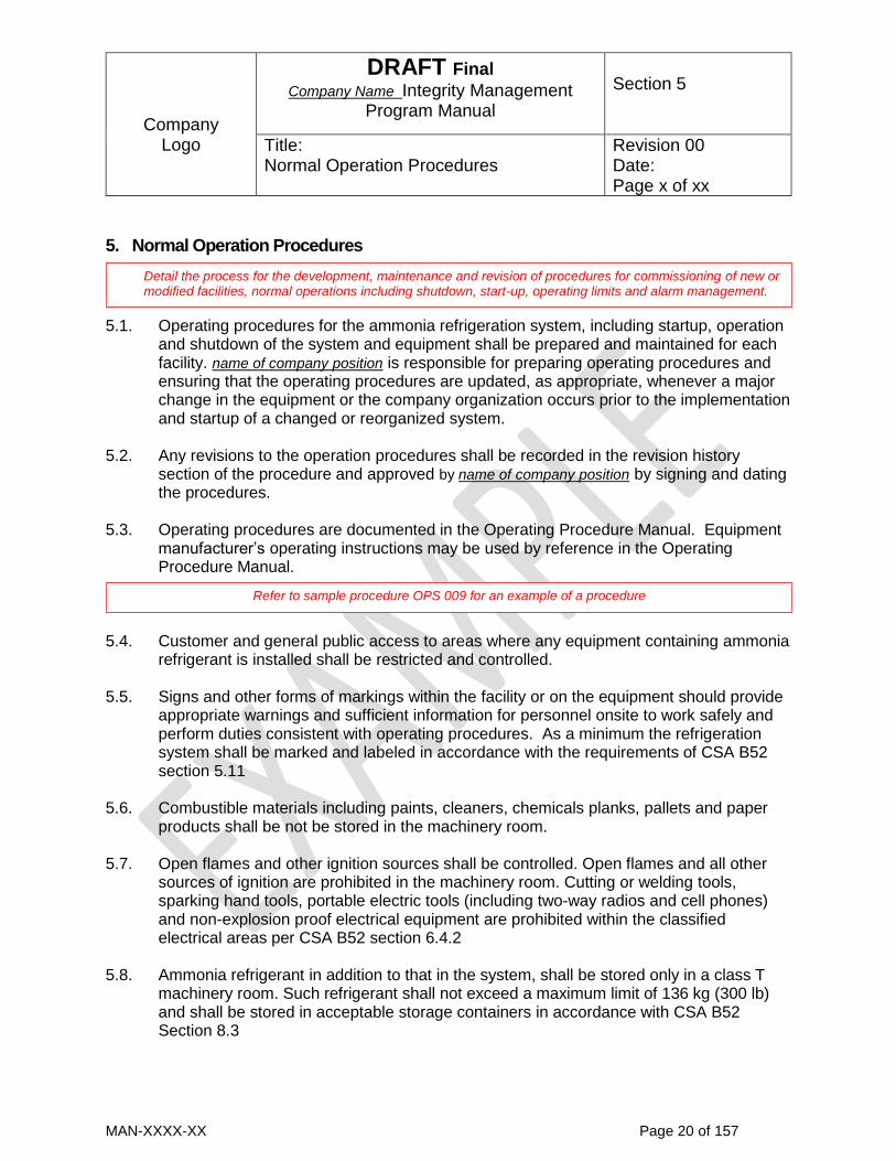
Company
Logo
DRAFT Final Company Name Integrity Management
Program Manual
Section 5
Title: Normal Operation Procedures
Revision 00 Date: Page x of xx
MAN-XXXX-XX Page 20 of 157
5. Normal Operation Procedures
5.1. Operating procedures for the ammonia refrigeration system, including startup, operation and shutdown of the system and equipment shall be prepared and maintained for each facility. name of company position is responsible for preparing operating procedures and ensuring that the operating procedures are updated, as appropriate, whenever a major change in the equipment or the company organization occurs prior to the implementation and startup of a changed or reorganized system.
5.2. Any revisions to the operation procedures shall be recorded in the revision history
section of the procedure and approved by name of company position by signing and dating the procedures.
5.3. Operating procedures are documented in the Operating Procedure Manual. Equipment
manufacturer’s operating instructions may be used by reference in the Operating Procedure Manual.
5.4. Customer and general public access to areas where any equipment containing ammonia
refrigerant is installed shall be restricted and controlled. 5.5. Signs and other forms of markings within the facility or on the equipment should provide
appropriate warnings and sufficient information for personnel onsite to work safely and perform duties consistent with operating procedures. As a minimum the refrigeration system shall be marked and labeled in accordance with the requirements of CSA B52 section 5.11
5.6. Combustible materials including paints, cleaners, chemicals planks, pallets and paper
products shall be not be stored in the machinery room. 5.7. Open flames and other ignition sources shall be controlled. Open flames and all other
sources of ignition are prohibited in the machinery room. Cutting or welding tools, sparking hand tools, portable electric tools (including two-way radios and cell phones) and non-explosion proof electrical equipment are prohibited within the classified electrical areas per CSA B52 section 6.4.2
5.8. Ammonia refrigerant in addition to that in the system, shall be stored only in a class T
machinery room. Such refrigerant shall not exceed a maximum limit of 136 kg (300 lb) and shall be stored in acceptable storage containers in accordance with CSA B52 Section 8.3
Detail the process for the development, maintenance and revision of procedures for commissioning of new or modified facilities, normal operations including shutdown, start-up, operating limits and alarm management.
Refer to sample procedure OPS 009 for an example of a procedure

Company
Logo
DRAFT Final Company Name Integrity Management
Program Manual
Section 5
Title: Normal Operation Procedures
Revision 00 Date: Page x of xx
MAN-XXXX-XX Page 21 of 157
5.9. The individual(s) performing ammonia transfer operations, filling or evacuating, must be
trained in ammonia handling procedures, procedures relevant and specific to the transfer operations, and emergency response procedures. During the transfer operation, from the time of original connection through the final disconnect, at least one trained individual must be in attendance. “In attendance” means that the individual must have line of sight of the transfer operation and be in a position to physically take action if required during the operation.

Company
Logo
DRAFT Final Company Name Integrity Management
Program Manual
Section 6
Title: Emergency Procedures
Revision 00 Date: Page x of xx
MAN-XXXX-XX Page 22 of 157
6. Emergency Procedures 6.1. Emergency procedures for incidents that could cause an unintentional or uncontrolled
release of ammonia or a potential safety or health hazard such as fires, explosions or chemical exposures, shall be prepared and maintained for each facility. These procedures shall consider the safety of emergency personnel, name of company workers and the public. name of company position is responsible for preparing emergency procedures and ensuring that the emergency procedures are updated, as appropriate prior to the startup of a changed system or a major change in the equipment and prior to the implementation of company organizational changes.
6.2. Any revisions to the emergency procedures shall be recorded in the revision history section of the procedure and approved by name of company position by signing and dating the procedures.
6.3. Emergency response procedures shall be documented in the Emergency Response
Plan Manual. The plan shall include: a) characteristics and properties of ammonia and the quantities in the refrigeration
system and storage b) a listing of information about chemical hazards in the facility, their material data
sheets, characteristics, properties, handling instructions, quantities and location c) a summary of the ammonia refrigeration system operation and a description of
probable emergencies scenarios and their potential consequences d) risk to neighboring areas and the public based on the impact of probable emergency
scenarios to surrounding areas e) a description of emergency management to direct and coordinate emergency
response including command, first aid, firefighting, evacuation wardens responsibilities
f) identification of emergency command post location g) processes for:
emergency plan activation establishment of safety perimeters and site access control emergency notification to buildings or sites adjacent to the facility activation of evacuation plan procedures to verify hazardous areas are evacuated and account for personnel
and public after evacuation initiation identifying company personnel in evacuation assembly area who could be used
to assist in emergency response identification of emergency responders (command, first aid, firefighting,
evacuation wardens, etc.)
h) emergency shut down of operating equipment before operators evacuate
Detail the process for the development, maintenance and revision of an emergency response and preparedness plan for an incident that could cause an unintentional or uncontrolled release of ammonia refrigerant, fire, explosion or expose individuals to chemical hazards..

Company
Logo
DRAFT Final Company Name Integrity Management
Program Manual
Section 6
Title: Emergency Procedures
Revision 00 Date: Page x of xx
MAN-XXXX-XX Page 23 of 157
i) evacuation paths from the danger area to a designated safe location when an emergency occurs including emergency escape routes, assembly points and shelter areas
j) locations of and hazards to areas/equipment in proximity to the refrigeration system that could be impacted by an ammonia release
k) designated safe locations separating the public from an ammonia release l) response to mitigate the impact of an ammonia leak to neighboring buildings,
installations or any other area m) emergency procedures to manage incidents including the use of emergency shut off
devices, electrical isolation and fire suppression n) emergency shutdown procedures and instructions on what to do during and after a
power failure o) considerations for the activation of an ammonia discharge system and the process to
do so p) procedures for contacting external emergency responders, ambulance, police and
Technical Safety BC q) post incident processes for a review and debrief of emergency procedure activation r) securing equipment and facility after an incident to preserve evidence for incident
investigation s) initiation of an investigation after an incident
6.4. Employees must be immediately evacuated from the danger area when an emergency
occurs, and employees are not permitted to assist in handling the emergency, unless they have received specialized training as detailed the following emergency operating procedures in the Emergency Response Manual:
EMP 001 Emergency Shutdown and Control of Ammonia Leaks
EMP 002 Steps to Take in the Event of an Accident Involving Ammonia
EMP 011 Emergency Response Guidelines
6.5. The following facility data and contact information shall be documented and posted in
the facility office for outside emergency response and support agencies:
a) type of facility b) company or organization’s name c) facility name (if different from the company or organization) d) facility’s street address e) city, province, postal code f) facility telephone number g) company or organization’s head office (city, province) and head office emergency
contact h) authorized/responsible facility emergency response representative title/position and
direct contact information (telephone, radio etc.)

Company
Logo
DRAFT Final Company Name Integrity Management
Program Manual
Section 6
Title: Emergency Procedures
Revision 00 Date: Page x of xx
MAN-XXXX-XX Page 24 of 157
6.6. The following contact information shall be documented and posted in the facility office for name of company emergency response team:
Fire Department (name): Telephone Number
Emergency Medical Responders (name):
Telephone Number
Hospital/ Emergency Medical Facility (name):
Telephone Number
Police (name):
Telephone Number
Refrigeration Contractor for emergency service
Telephone Number
Technical Safety BC Incident or Hazard Reporting Regional Technical Safety Office Boiler Safety Officer (name)
Telephone Numbers
6.7. Material Safety Data Sheets for hazardous chemicals shall be filed and maintained in a
dedicated file cabinet in the facility office. 6.8. name of company position is responsible for preparing and maintaining a facility site plan
that identifies the location of emergency switches, fire protection systems and emergency response equipment. The plan shall be posted in the facility office. The following information shall be included in the site plan:
a) compass directions north/south for orientation b) property lines, adjacent roads and adjacent properties c) fence lines and vehicle or personnel gates d) buildings and structures, identified by name and general function e) machinery room location f) plan of the machinery room showing major equipment and exits g) machinery room ventilation air inlet/outlet discharge and fan start/stop switch
locations h) location of remote machinery shutdown switch outside of machinery room i) location of emergency ammonia discharge valve and the location of its discharge to
atmosphere j) location of pressure relief valve discharge k) plan of piping containing ammonia located outside of the machinery room l) ammonia detectors and alarm locations m) ammonia storage location and amount of ammonia stored n) facility electrical system controls (i.e., switch gear, main panel, breaker box) o) location of principle refrigeration system control panel and remote control switches

Company
Logo
DRAFT Final Company Name Integrity Management
Program Manual
Section 6
Title: Emergency Procedures
Revision 00 Date: Page x of xx
MAN-XXXX-XX Page 25 of 157
p) emergency shutoff valves (location of valve and remote control device) q) fire monitoring, detection and suppression equipment
- hydrants and hose stations - sprinkler systems - extinguishers - other sources of water for emergency response
r) emergency escape routes, assembly points and shelter areas to be used in emergencies
s) location of emergency response personal protective equipment 6.9. Emergency equipment and controls shall be marked with signs. Lettering shall be a
minimum of 1/2 in. (13 mm) high and shall be red on a white background . Emergency equipment and controls shall be installed in locations that will be accessible in emergency situations.
6.10. name of company position is designated to verify hazardous areas are evacuated and
account for personnel and public after evacuation initiation.
6.11. An emergency evacuation exercise shall be carried out at least every 6 months.
6.12. One procedure from the Emergency Management Plan shall be tested at least every 12 months by conducting an emergency response exercise.
6.13. The full Emergency Response Plan shall be tested at least every 5 years by conducting an emergency response exercise.
6.14. After every emergency response exercise the exercise shall be reviewed and the
adequacy of the processes, training and response of the emergency management team evaluated. Lessons learned shall be incorporated into the emergency response procedures in accordance with section 6.1

Company
Logo
DRAFT Final Company Name Integrity Management
Program Manual
Section 7
Title: Inspection and Monitoring
Revision 00 Date: Page x of xx
MAN-XXXX-XX Page 26 of 157
7. Inspection and Monitoring
7.1. This section defines the responsibility and policies for conducting inspection, testing and monitoring of the ammonia refrigeration facilities. Inspection and monitoring performed by _company name_ at ammonia refrigeration facilities will be completed in accordance with the current the Safety Standards Act, Safety Standards General Regulation, Power Engineers, Boiler, Pressure Vessel and Refrigeration Safety Regulation, CSA B51 and CSA B52 and all other applicable codes.
7.2. Written procedures provided by equipment manufacturers may be used as manuals for
the inspection and testing of ammonia refrigeration equipment. 7.3. _ name of company position will prepare inspection and testing procedures. All procedures
shall conform to equipment manufacturer’s recommendations and applicable codes or standards. Inspection and maintenance procedures shall include the frequency of inspection or testing determined in in accordance with CSA B52 section 8.4.4 and NBIC Part 2 section 4.4.7 for equipment not covered by CSA B52.
7.4. Any revisions to the inspection procedures shall be recorded in the revision history section of the procedure and approved by name of company position by signing and dating the procedures.
7.5. Inspection results will be reviewed at least every 12 months to determine equipment deterioration rates. Based on annual review of inspection results, inspection frequencies may be have to be increased to adequately monitor defects. Revision of frequencies shall be in accordance with NBIC Part 2 section 4.4.7.
7.6. Equipment specific inspection plans and strategies for new equipment monitoring shall be developed and implemented within six months of equipment installation. Existing inspection plans will be reviewed annually and updated as required based on inspection results, revisions to codes, advances in technology, and other information.
7.7. All inspection and testing will be carried out in accordance with the procedures prepared
by _ name of company position . These procedures shall be documented in the Inspection Procedure Manual.
This section of the manual is intended to provide the administrative controls and information necessary to develop, implement and update inspection and monitoring procedures for ammonia refrigeration systems and equipment. These processes should be designed to ensure safe operation and to mitigate risks. Inspection and monitoring activities should follow relevant regulations, standards, codes and equipment manufacturer’s instructions. The manual may include detailed inspection procedures or refer to written procedures documented independently from the manual or written procedures provided by equipment manufacturers. The manual will identify the name and title of the individual responsible for the implementation and administration of these procedures.
Refer to sample procedure IP 009 for an example of a procedure

Company
Logo
DRAFT Final Company Name Integrity Management
Program Manual
Section 7
Title: Inspection and Monitoring
Revision 00 Date: Page x of xx
MAN-XXXX-XX Page 27 of 157
7.8. Upon completion of the inspection and testing procedure, the _ name of company position
will store all documentation in the inspection and testing file. This file shall be retained for service life of the equipment. All documentation is subject to audit by Technical Safety BC. Inspection and testing records provide the tracking and documented verification that the facility is being properly maintained and in a safe condition in accordance with CSA B52 Section 8.4 and the Safety Standards Act. Inspection and testing records for all ammonia refrigeration equipment shall be kept at address of facility.
7.9. Individuals carrying out inspection and testing procedures shall be trained on the
inspection and testing procedures applicable to the systems or equipment on which they are working.
7.10. Emergency shutoff valves (ESVs) shall be tested at least every 12 months for their
functionality. ESVs must be specifically tested for: a) manual shutoff from a remote location if so equipped . b) manual shutoff at the valve
7.11. The mechanical equipment emergency shut down control outside of the machinery room
shall be tested for functionality at least every 12 months. 7.12. The machinery room ammonia detection system shall be calibrated and functionally
tested to verify it activates the mechanical ventilation system and the visual/audible alarms at an ammonia concentration of 300 ppm at least every 12 months.
7.13. Pressure-relief valves shall be replaced or recertified at intervals no longer than five
years. 7.14. Pressure-limiting devices shall be tested at least once every 12 months for set point
accuracy and that they function to stop the equipment which they protect. 7.15. All power and control electrical terminations shall be inspected at least once every 12
months. 7.16. The brine secondary coolant system shall be tested for ammonia leakage into the brine
at least every 6 months in accordance with Safety Order SO-BP-2017-01. 7.17. All ammonia leaks must be immediately repaired or the leaking equipment removed from
service. 7.18. Any damaged, deteriorating equipment or unsafe conditions identified during
inspections shall be evaluated in accordance with the guidelines of the codes adopted in the Schedule of the Power Engineers, Boiler, Pressure Vessel and Refrigeration

Company
Logo
DRAFT Final Company Name Integrity Management
Program Manual
Section 7
Title: Inspection and Monitoring
Revision 00 Date: Page x of xx
MAN-XXXX-XX Page 28 of 157
Safety Regulation to determine if the equipment is fit for its intended service. Equipment that is not fit for service shall be repaired or removed from service and replaced.
7.19. _ name of company position shall track completed, due and past due inspections. A monthly report on inspection status shall be prepared and forwarded to individuals responsible for inspections. Follow up on due and past due inspections shall be carried out. Past due inspections shall be completed or incompletions shall be substantiated and documented.

Company
Logo
DRAFT Final Company Name Integrity Management
Program Manual
Section 8
Title: Installation, Maintenance and Repair Methods
Revision 00 Date: Page x of xx
MAN-XXXX-XX Page 29 of 157
8. Installation, Maintenance and Repair Methods
8.1. This section defines the responsibility and policies for conducting installation, maintenance and repairs to ammonia refrigeration plants. Repairs and alterations to ammonia refrigeration plants performed by _company name_ will be completed in accordance with the current the Safety Standards Act, Power Engineers, Boiler, Pressure Vessel and Refrigeration Safety Regulation, CSA B52, CSA B51and all other applicable codes.
8.2. Repairs are defined as work necessary to restore ammonia refrigeration plants to a safe operating condition, provided there is no change from the original design.
8.3. _ name of company position is responsible for ensuring all installation and repair of
equipment in ammonia refrigeration plants conform to the procedures detailed in this manual and is responsible for the completion of any documentation required by this manual or the Safety Standards Act.
8.4. _ name of company position is responsible for verifying that permits for installations or repairs are obtained in accordance with the Power Engineers, Boiler, Pressure Vessel and Refrigeration Safety Regulation section 62 before work is started unless work is carried out in accordance with section 63(2) of the Regulation. If emergency repairs are necessary they shall be carried out in accordance with the Power Engineers, Boiler, Pressure Vessel and Refrigeration Safety Regulation section 86.
8.5. Written installation, maintenance and repair procedures provided by equipment
manufacturers may be used as manuals for the installation, maintenance or repair of ammonia refrigeration equipment.
8.6. _ name of company position will prepare installation, maintenance and repair procedures.
All procedures shall conform to equipment manufacturer’s recommendations and applicable codes.
8.7. Any revisions to the procedures shall be recorded in the revision history section of the procedure and approved by name of company position by signing and dating the procedures.
8.8. All work will be carried out in accordance with the installation, maintenance and repair procedures prepared by _ name of company position .
This section of the manual is intended to provide the administrative controls and information necessary to develop, implement and update procedures used to maintain the mechanical integrity of an ammonia refrigeration plant in compliance with CSA B51 and B52 . The manual may include detailed procedures for the work or refer to written maintenance procedures documented independently from the manual or written maintenance procedures provided by equipment manufacturers. The manual will identify the name and title of the individual responsible for the implementation and administration of these procedures.

Company
Logo
DRAFT Final Company Name Integrity Management
Program Manual
Section 8
Title: Installation, Maintenance and Repair Methods
Revision 00 Date: Page x of xx
MAN-XXXX-XX Page 30 of 157
8.9. Upon completion of the installation, maintenance and repair procedure, the _ name of
company position will record all documentation in the installation/repair file. These records shall be retained for the service life of the equipment. All documentation is subject to audit by Technical Safety BC. Installation/repair records provide tracking and documented verification that the ammonia refrigeration plant is being maintained to preserve the operating efficiencies, equipment integrity, personal protection and protection of the building and natural environments in accordance with CSA B52 and the Safety Standards Act. Repair records for all equipment shall be kept at address of dispensing facility.
8.10. All installation, maintenance and repair records shall contain the following information as
applicable: date
equipment identification
maintenance procedure
description of as found condition before maintenance
description of deficiency for repairs
description of repair performed
name or identification of persons/contractor developing repair procedure, approving
repair procedure, carrying out repair, and verifying repair completed satisfactorily
name or identification of persons/contractor developing installation procedure,
approving installation procedure, carrying out installation, and verifying installation
completed satisfactorily
qualification of persons carrying out installation, maintenance or repair
copy of installation permit
date and name of person notifying Technical Safety BC of an installation or repair
name of safety officer approving repair method; any documentation of this
notification or repair acceptance
date and name of person notifying Technical Safety BC of installation or repair
completion and requesting an inspection; name of safety officer informed
repair report certifying that the repair was done in accordance with the Power
Engineers, Boiler, Pressure Vessel and Refrigeration Safety Regulation
safety officer’s inspection report for installation or repair
8.11. Individuals performing refrigeration equipment installation, maintenance or repairs shall
be trained in the hazards of ammonia, installation, maintenance or repair procedures applicable to the systems or equipment on which they are working. All contractors carrying out equipment installation/repairs must train the personnel under their supervision in the hazards of ammonia and in installation/repair and testing procedures applicable to the systems or equipment on which they are working or ensure that personnel working on equipment are under the supervision of a properly trained

Company
Logo
DRAFT Final Company Name Integrity Management
Program Manual
Section 8
Title: Installation, Maintenance and Repair Methods
Revision 00 Date: Page x of xx
MAN-XXXX-XX Page 31 of 157
individual. _ name of company position is responsible for verifying that the contractor has documented training records.
8.12. Maintenance and repair reports will be reviewed annually by _ name of company position to evaluate damage mechanism impacts, deterioration rates and remaining service life. Maintenance schedules maybe revised based on past repairs, maintenance reports and inspection results.
8.13. _ name of company position shall track completed, due and past due maintenance/repair work. A monthly report on maintenance/repair status shall be prepared and forwarded to individuals responsible for repair work. Follow up on due and past due maintenance/repair work shall be carried out. Past due maintenance/repairs shall be completed or incompletions shall be substantiated and documented in the maintenance and repair files.
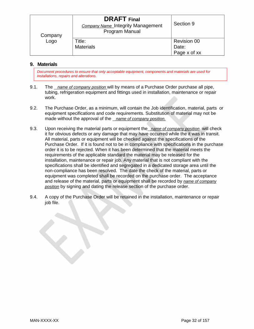
Company
Logo
DRAFT Final Company Name Integrity Management
Program Manual
Section 9
Title: Materials
Revision 00 Date: Page x of xx
MAN-XXXX-XX Page 32 of 157
9. Materials
9.1. The _ name of company position will by means of a Purchase Order purchase all pipe,
tubing, refrigeration equipment and fittings used in installation, maintenance or repair work.
9.2. The Purchase Order, as a minimum, will contain the Job identification, material, parts or equipment specifications and code requirements. Substitution of material may not be made without the approval of the _ name of company position.
9.3. Upon receiving the material parts or equipment the_ name of company position will check it for obvious defects or any damage that may have occurred while the it was in transit. All material, parts or equipment will be checked against the specifications of the Purchase Order. If it is found not to be in compliance with specifications in the purchase order it is to be rejected. When it has been determined that the material meets the requirements of the applicable standard the material may be released for the installation, maintenance or repair job. Any material that is not compliant with the specifications shall be identified and segregated in a dedicated storage area until the non-compliance has been resolved. The date the check of the material, parts or equipment was completed shall be recorded on the purchase order. The acceptance and release of the material, parts or equipment shall be recorded by name of company
position by signing and dating the release section of the purchase order. 9.4. A copy of the Purchase Order will be retained in the installation, maintenance or repair
job file.
Document procedures to ensure that only acceptable equipment, components and materials are used for installations, repairs and alterations.

Company
Logo
DRAFT Final Company Name Integrity Management
Program Manual
Section 10
Title: Incident and Near-miss Investigation
Revision 00 Date: Page x of xx
MAN-XXXX-XX Page 33 of 157
10. Incident and Near-miss Investigation
10.1. An incident is a failure of ammonia refrigeration equipment resulting from work or operation that causes damage to property, personal injury/death or damage to safety features. Property damage or injury focuses on the impact that the failed equipment may have had to other equipment, property or individuals near or adjacent to the ammonia refrigeration facility. Damage to safety features relates to failures where the damage is limited to the failed equipment, does not render the equipment inoperative but impairs the safety feature’s effectiveness. A safety feature is an aspect of a refrigeration system’s design, installation, maintenance or operation that is intended to prevent people or property from being exposed to a hazard.
10.2. A hazard is anything that has the potential to create an incident or may cause harm to
persons or property damage. All hazards will be immediately corrected. Hazards shall be immediately reported to Technical Safety BC when: a) the hazard cannot be immediately corrected or: b) the same or similar hazard has repeatedly occurred.
10.3. All incidents and hazards shall be reported to Technical Safety BC in accordance with
the Safety Standards Act section 36, the Safety Standards General Regulation section 34, the Power Engineers, Boiler, Pressure Vessel and Refrigeration Safety Regulation section 66 and Information Bulletin IB-BP 2017-01. Name of company position is responsible for reporting to Technical Safety BC.
10.4. Incidents and hazards shall be reported to Technical Safety BC using the link “Report an
Incident or Hazard” on their website at https://www.technicalsafetybc.ca/report-incident-hazard or their contact center at 1-866-566-7233. Reporting incidents and
hazards by voicemail and email messages to Technical Safety BC employees other than the through Technical Safety BC webpage link or the contact center, are not considered to have been reported to Technical Safety BC as required by regulation.
10.5. The date, time and method used to report the incident to Technical Safety BC shall be documented and recorded in the incident report as required in section 10.15.
10.6. Incidents resulting in an injury, fatality, damage to equipment or property shall be
reported as soon as practicable and not longer than 24 hours after the incident. The ammonia refrigeration equipment must be shut down and isolated. It shall not be placed back into service until authorized by Technical Safety BC.
Provide a description of the system used to ensure that accidents and unsafe conditions involving ammonia refrigeration equipment are reported in accordance with regulatory requirements. A formalized process for internal reporting of accidents, incidents and near-miss events, determining their root cause and taking appropriate action to prevent their recurrence should be established.

Company
Logo
DRAFT Final Company Name Integrity Management
Program Manual
Section 10
Title: Incident and Near-miss Investigation
Revision 00 Date: Page x of xx
MAN-XXXX-XX Page 34 of 157
10.7. Unless it is necessary to rescue a person, prevent injury or to protect property no one
shall remove, disturb or interfere with anything in, on or about the place where an incident has occurred.
10.8. Any ammonia refrigeration equipment beyond repair or in an unsafe condition must be
taken out of service or otherwise made safe. Name of company position shall promptly notify Technical Safety BC about the equipment’s condition and location.
10.9. Name of company position shall be immediately be notified of all incidents, hazards and
any equipment in an unsafe condition. Name of company position shall ensure that the incident or hazard scene is secured and equipment is made safe.
10.10. Name of company position shall control the scene of an incident or hazard to ensure that
the site is not disturbed by: a) establishing a physical perimeter around the incident/hazard site to restrict access b) assigning an individual to control the entry to the incident/hazard site c) posting signs to ensure unauthorized persons do not enter the incident/hazard site d) maintain a log to record the names and times of persons who enter/leave the
incident/hazard site and any evidence found or moved at the site
10.11. Name of company position shall ensure the incident/hazard site is safe before entering. Name of company position shall determine what safety equipment is required to safely enter the incident/hazard site and all investigators entering the site shall use the prescribed safety equipment.
10.12. Name of company position is responsible for incident/hazard investigation and shall collect evidence consisting of testimonies, records, documents, and damaged objects including: a) the names of everyone involved, near, present or aware of the possible contributing
factors or sequence of events. b) information about the design and operation of the device or equipment involved,
failures of equipment or safety devices and non-compliances to codes or standards. c) the exact location, note all relevant facts, including lighting, weather, and operating
conditions at the time of the incident d) the exact time, date, and other operational factors that may have contributed to the
incident/hazard such as shift change, maintenance schedules, etc. e) a description of both the normal sequence of events and actual sequence of events
before, during, and after the incident f) test results or findings from examinations of the equipment involved in the incident g) visual observations, photographs or sketches of the scene
10.13. Name of company position shall interview witnesses as soon as possible after the incident/hazard to maximize the accuracy of their information, collect and reconstruct

Company
Logo
DRAFT Final Company Name Integrity Management
Program Manual
Section 10
Title: Incident and Near-miss Investigation
Revision 00 Date: Page x of xx
MAN-XXXX-XX Page 35 of 157
factual accounts of the incident/hazard. Witness statements shall be documented and signed by the witnesses.
10.14. Incident investigators shall identify possible direct and indirect causes to determine the
fundamental cause of the incident. If required external technical experts, shall be used to conduct specialized tests or examinations. Determine whether the incident occurred due to non-compliance with regulations or codes or standards or any other safety issues.
10.15. Name of company position shall prepare a written incident/hazard report that documents:
a) a summary of the incident/hazard investigation process including actions taken, witnesses, evidence collected and photographs
b) what, where, when, how, and why it happened. c) who was involved d) actual or potential fatalities, injuries, or property damage. e) any regulatory non-compliances or other safety issues that may have caused the
incident or contributed to it f) any other non-compliances observed during the investigation. g) recommended corrective actions and follow-up inspection activities to ensure
corrective action is completed and effective in preventing further incidents/hazards
10.16. All incident/hazards reports shall be reviewed and accepted by Name of company position
10.17. _ name of company position shall track completed, due and past due corrective actions and follow-up inspection activities. Past due actions shall be completed or incompletions shall be substantiated and documented in the incident report file.

Company
Logo
DRAFT Final Company Name Integrity Management
Program Manual
Section 11
Title: Change Management
Revision 00 Date: Page x of xx
MAN-XXXX-XX Page 36 of 157
11. Change Management
11.1. The management of change procedure applies to any permanent or temporary change
in the design, construction, installation, operation, maintenance procedures or decommissioning of the ammonia refrigeration system.
11.2. The change management process applies to any change including: a) new ownership of a facility, b) staff reorganization resulting in modifications to functional responsibilities and levels
of authority for individuals operating and maintaining the facility, c) installation of new equipment or alterations to equipment, process technology or
control systems d) variations of maintenance/operating processes e) implementation of temporary operating conditions such as idling of equipment for
inspection/maintenance/repair, facility shutdown, or decommissioning which can introduce “temporary” hazards not expected during normal operations
f) revised or new standards, codes or regulations which impose adjustments to the operation or maintenance of the refrigeration system
g) alterations required due to environmental factors, such as flood, fire, ground movement
h) adjacent property development that alters the risk to neighboring areas that may be impacted by ammonia discharge from pressure relief valves or emergency discharge systems and other emergencies
11.3. name of company position is responsible to review revisions and new editions of the Safety
Standards Act, the Power Engineers, Boiler, Pressure Vessel and Refrigeration Safety Regulation and CSA B51 and B52 to identify any required changes to the program manual as a result of legislative or code changes. This review shall be documented and maintained in the program records.
11.4. Whenever a change in equipment, facility operation or administration occurs the
equipment integrity maintenance management program shall be reviewed to assess the impact of changes. Any affected operation, emergency and maintenance procedure(s) shall be updated. The review and revisions shall be recorded in the revision history for the procedure.
11.5. A change in facility ownership, organization or position responsibilities requires a review of the equipment integrity maintenance management program. Any section of the equipment integrity maintenance management program impacted by the changes shall
Management of change is a formal system to evaluate, authorize, and document changes before they are made and to ensure that the changes made do not adversely affect integrity or safety within the facility. Provide a description of the management of change procedures.

Company
Logo
DRAFT Final Company Name Integrity Management
Program Manual
Section 11
Title: Change Management
Revision 00 Date: Page x of xx
MAN-XXXX-XX Page 37 of 157
be revised. Any affected operation, emergency and maintenance procedure(s) shall be updated. The review and revisions shall be recorded in the revision history for the program manual or procedure.
11.6. If the property adjacent to an ammonia refrigeration facility is rezoned, developed or the use of the property changes, the impact of ammonia releases must be re-evaluated. The equipment integrity maintenance management program shall be reviewed and any operation, emergency or maintenance procedure(s) that could impact the neighboring property shall be updated. The review and revisions shall be recorded in the revision history for the procedure.
11.7. name of company position is responsible for conducting a pre-startup safety review prior to
implementing any change. A checklist of requirements shall be developed for every change. Their completion shall be verified and documented prior implementing a change. The verified checklist shall be filed in the program records.
11.8. name of company position shall ensure that personnel are aware of any change to
operating or maintenance procedures and trained to address its impact to their work.
Training shall be included in the pre-startup checklist.
11.9. name of company position shall ensure records of all changes are maintained. The
record of change shall include:
a) a description of the change b) summary of management of change review and results c) authorization and approvals of any changes in accordance with Section 1.1 d) regulatory approvals e) revision and updates to operating and or maintenance procedures f) training provided and verification of staff competency for revised operating and or
maintenance procedures g) pre-startup checklists and verifications
Company
Logo
DRAFT Final Company Name Integrity Management
Program Manual
Section 12
Title: Internal Audits
Revision 00 Date: Page x of xx
MAN-XXXX-XX Page 38 of 157
12. Internal Audits
12.1. Both planned periodic audits and unplanned audits of equipment integrity management program procedures and operation/maintenance activities shall be carried out to verify compliance with the applicable requirements of the program. The audits are conducted to determine to the program’s effectiveness and identify areas for improvement. At a minimum a planned audit must be performed at least every 12 months.
12.2. The Name of company position shall appoint an auditor to carry out program audits. The auditor shall not have any direct responsibility in any areas being audited. The auditor shall have knowledge of: a) audit principles, procedures and techniques b) the requirements of the ammonia refrigeration facility equipment integrity
management program c) the requirements of CSA B52 and CSA B51 d) ammonia refrigeration plant operations, inspection, maintenance and repairs
12.3. The audits shall be documented by the auditor and the results shall be reviewed by
Name of company position. Follow-up actions, including re-audit of deficient areas shall be carried out by the auditor to verify that deficiencies have been corrected.
12.4. Audits shall be performed using an audit checklist covering the requirements of this
program. It will also serve as the audit report. Any non-conformances that are identified during the audit shall be addressed and the action taken documented. The auditor is responsible for following-up on the audit findings and ensuring that actions were completed. Non-conformances should be recorded on a non-conformance report (Exhibit 05).
12.5. Name of company position is responsible to maintain records of audit documentation which
shall be made available upon request to Technical Safety BC for review. 12.6. All Name of company personnel shall report conditions or activities which are not
conducted in accordance with this equipment integrity management program. When such an activity or condition is identified, it shall be documented and submitted to Name
of company position who shall review the documentation to determine the corrective actions and preventive actions necessary to prevent reoccurrences. Name of company
position may authorize an unplanned audit if: a) there is any doubt about compliance with the equipment integrity management
Document the procedures for conducting internal audits which are conducted to verify that the equipment integrity management program has been implemented correctly and assess the effectiveness of the program. These procedures should define the responsibilities as well as detail the scope, objectives, frequency, and schedule for internal audits.

Company
Logo
DRAFT Final Company Name Integrity Management
Program Manual
Section 12
Title: Internal Audits
Revision 00 Date: Page x of xx
MAN-XXXX-XX Page 39 of 157
program requirements or b) if the cause of the issue is not apparent and effective corrective actions cannot be
developed Records of the corrective actions shall be maintained.
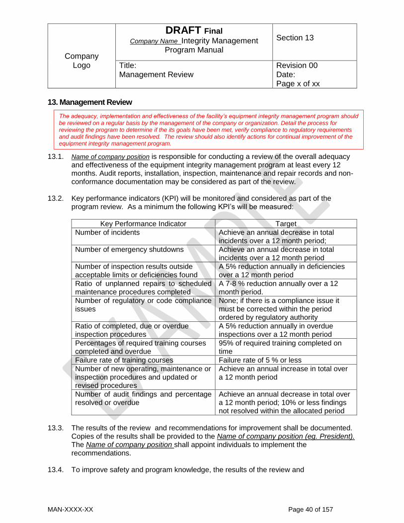
Company
Logo
DRAFT Final Company Name Integrity Management
Program Manual
Section 13
Title: Management Review
Revision 00 Date: Page x of xx
MAN-XXXX-XX Page 40 of 157
13. Management Review
13.1. Name of company position is responsible for conducting a review of the overall adequacy
and effectiveness of the equipment integrity management program at least every 12 months. Audit reports, installation, inspection, maintenance and repair records and non-conformance documentation may be considered as part of the review.
13.2. Key performance indicators (KPI) will be monitored and considered as part of the program review. As a minimum the following KPI’s will be measured:
Key Performance Indicator Target
Number of incidents Achieve an annual decrease in total incidents over a 12 month period;
Number of emergency shutdowns Achieve an annual decrease in total incidents over a 12 month period
Number of inspection results outside acceptable limits or deficiencies found
A 5% reduction annually in deficiencies over a 12 month period
Ratio of unplanned repairs to scheduled maintenance procedures completed
A 7-8 % reduction annually over a 12 month period.
Number of regulatory or code compliance issues
None; if there is a compliance issue it must be corrected within the period ordered by regulatory authority
Ratio of completed, due or overdue inspection procedures
A 5% reduction annually in overdue inspections over a 12 month period
Percentages of required training courses completed and overdue
95% of required training completed on time
Failure rate of training courses Failure rate of 5 % or less
Number of new operating, maintenance or inspection procedures and updated or revised procedures
Achieve an annual increase in total over a 12 month period
Number of audit findings and percentage resolved or overdue
Achieve an annual decrease in total over a 12 month period; 10% or less findings not resolved within the allocated period
13.3. The results of the review and recommendations for improvement shall be documented.
Copies of the results shall be provided to the Name of company position (eg. President). The Name of company position shall appoint individuals to implement the recommendations.
13.4. To improve safety and program knowledge, the results of the review and
The adequacy, implementation and effectiveness of the facility’s equipment integrity management program should be reviewed on a regular basis by the management of the company or organization. Detail the process for reviewing the program to determine if the its goals have been met, verify compliance to regulatory requirements and audit findings have been resolved. The review should also identify actions for continual improvement of the equipment integrity management program.

Company
Logo
DRAFT Final Company Name Integrity Management
Program Manual
Section 13
Title: Management Review
Revision 00 Date: Page x of xx
MAN-XXXX-XX Page 41 of 157
recommendations for improvement shall be promulgated to any individual assigned equipment integrity management responsibilities.
13.5. Name of company position shall review monthly inspection and maintenance/repair status reports. Name of company position shall follow up on past due inspection and maintenance/repair work to verify that the work is completed or incompletions are substantiated and documented.
13.6. Name of company position shall review annual internal audit reports and verify non-conformances are resolved.

Company
Logo
DRAFT Final Company Name Integrity Management
Program Manual
Section 14
Title: Nonconforming Items
Revision 00 Date: Page x of xx
MAN-XXXX-XX Page 42 of 157
14. Nonconforming Items 14.1. A non-conformity is any condition which does not meet the requirements of this manual,
Regulations or codes. This includes physical non-conformities found during receiving of materials, those found during fabrication and final testing. It also includes errors and omissions in documentation.
14.2. When it has been determined that a non-conformity exists, the items shall be marked
and identified as non-conforming until resolution of the issue. 14.3. In respect to non-conformities with material, parts or equipment, the non-conforming
item will be rejected and discarded, returned to the supplier or repaired and used. Repaired items must be accepted by name of company position (eg. quality control manager), signing and dating the non-conformance report.
14.4. It is the responsibility of all employees to identify non-conformities. name of company
position (eg. quality control manager) shall document and record all non-conformities on a nonconformance report which will be placed in the permanent job file. All non-conformities shall be resolved to the satisfaction of name of company position (eg. quality
control manager). Resolution of non-conformities shall be recorded by name of company
position (eg. quality control manager) signing and dating the non-conformance report.

Company
Logo
DRAFT Final Company Name Integrity Management
Program Manual
Exhibit 01
Title: Appointment Record
Revision 00 Date: Page x of xx
MAN-XXXX-XX Page 43 of 157
Appointment Record Name
Certificate of Qualification
Certificate of Qualification Class Number
Certificate of Qualification Expirary Date
This certifies that the above named person holds the certificate of qualification required by this program and the Power Engineers, Boiler, Pressure Vessel and Refrigeration Safety Regulation and is hereby appointed to be the individual in charge of the ammonia refrigeration plant (plant registration number) at plant address Certified Date
name of company position

Company
Logo
DRAFT Final Company Name Integrity Management
Program Manual
Exhibit 02
Title: Certification Record
Revision 00 Date: Page x of xx
MAN-XXXX-XX Page 44 of 157
Certification Record Name
Assigned Duty
Certificate of Qualification
Certificate of Qualification Class Number
Certificate of Qualification Expirary Date
This certifies that the above named person holds the certificate of qualification required by this program and the Power Engineers, Boiler, Pressure Vessel and Refrigeration Safety Regulation. The individual has completed the training for the named duties and has the competency to carry out the assigned duties Certified Date
name of company position

Company
Logo
DRAFT Final Company Name Integrity Management
Program Manual
Exhibit 03
Title: Employee Training Record
Revision 00 Date: Page x of xx
MAN-XXXX-XX Page 45 of 157
Employee Training Record Training Record
Name: __________________________________
DATE OF
TRAINING DESCRIPTION OF TRAINING
SATISFACTORY
COMPLETION
YES NO
TRAINER’S
NAME
TRAINER’S
SIGNATURE

Company
Logo
DRAFT Final Company Name Integrity Management
Program Manual
Exhibit 04
Title: Non Conformance Report
Revision 00 Date: Page x of xx
MAN-XXXX-XX Page 46 of 157
Contractor Verification Record
Name of Contractor
Job Number
Class of Contractor’s License
Contractor’s License Number
Contractor’s License Expirary Date
This certifies that is has been verified that the above named contractor holds the appropriate class of license for the regulated work and that the work to be performed is within the scope of the contractor’s quality control program manual accepted by Technical Safety BC.
Certified Date
name of company position Individuals employed by the contractor to do regulated work are qualified in accordance with section 5 of the Power Engineers, Boiler, Pressure Vessel and Refrigeration Safety Regulation.
Name Qualification/Class of Certificate of
Qualification Expiry Date

Company
Logo
DRAFT Final Company Name Integrity Management
Program Manual
Exhibit 04
Title: Non Conformance Report
Revision 00 Date: Page x of xx
MAN-XXXX-XX Page 47 of 157
NON CONFORMANCE REPORT
Reported by: Date File
Number
Non Conformance Related to ☐ Code ☐ Manual ☐ Procedure ☐ Documentation*
Description of non-conformance
Background information
Actions taken:
Approved by
Administrator Date Reported:
*Documentation: Contract, Form, Log, Report etc

Company
Logo
DRAFT Final Company Name Operation Procedure Manual
OPS-009
Title: Ammonia Compressor Operation
Revision 00 Date: Page x of xx
MAN-XXXX-XX Page 48 of 157
1. Purpose
1.1. To detail the startup and operational procedures for the ammonia compressor.
2. Scope 2.1. This procedure applies to the Crazy Horse Mark III reciprocating compressor
installed in the refrigeration plant at the Smith Memorial Arena, Anytown BC.
3. Responsibility
3.1. name of company position (eg. maintenance supervisor) is responsible for: - ensuring individuals starting and operating the compressor have completed
training on this procedure and are competent to operate the compressor - informing employees of equipment issues effecting compressor operation
before they operate the compressor - addressing any equipment problems or safety issues raised by employees
about the compressor 3.2. Individuals operating the compressor are responsible for:
- adhering to this operating procedure when operating the compressor - stopping work if they consider any procedure or operation to be unsafe until
the safety issue is resolved - informing supervisory staff of stop work issues, equipment deficiencies,
issues or safety problems 4. Procedure
4.1. Individuals operating the compressor shall use PPE: - safety glasses - safety footware - hearing protection
4.2. Individuals operating the compressor should be prepared for the possibility of an
ammonia leak and have completed training for operating procedure OPS 012 Steps to Take in the Event of an Ammonia Leak.
4.3. Prior to starting:
Ensure discharge line is open - Open isolation valve X1 - Open high pressure receiver valves X4 and X5 - Open condenser valves X5 and X6

Company
Logo
DRAFT Final Company Name Operation Procedure Manual
OPS-009
Title: Ammonia Compressor Operation
Revision 00 Date: Page x of xx
MAN-XXXX-XX Page 49 of 157
Verify emergency shut down valve X2 is open
Close block valve X3 on the compressor bypass line
Check for sufficient oil in crankcase sump window
Ensure suction line is open: - open isolation valve S1 - open LP receiver isolation valve S2
Open water supply valve W1 for compressor jackets and oil cooler
4.4. Starting the compressor:
Ensure compressor is unloaded; unloader solenoids in open position
Start compressor using local start/stop switch
Once compressor is up to speed and oil pressure has stabilized at XX psi load compressor by closing bypass valve X3
Monitor compressor until operating pressure of XXX-XXX psi is reached
Monitor compressor to ensure it is operating within acceptable limits: - outlet pressure xxx-xxx psi - outlet temperature xx0F - oil pressure xx psi - oil temperature xx0F
4.5. Shutting down the compressor:
Stop the compressor using local start/stop switch or from DCS panel
Isolate compressor: - close suction line isolation valve S1 - close discharge line isolation valve X1 - shut off water to compressor and oil cooler by closing valve W1
5. Reference Documents
Crazy Horse Manufacturing Mark III Reciprocating Compressor Operation Manual 6. Revision History
Revision Level Date Details Revised By (enter name)
00 Sep. 10, 2019 Initial Issue A. Smith
Company
Logo
DRAFT Final Company Name Operation Procedure Manual
OPS-009
Title: Ammonia Compressor Operation
Revision 00 Date: Page x of xx
MAN-XXXX-XX Page 50 of 157
This procedure has been: Prepared by:
Title Date Reviewed by:
Title Date Approved by:
Title Date
Name
Name
Name

Company
Logo
DRAFT Final Company Name Inspection Procedure Manual
IP-009
Title: Inspection of Uninsulated Piping
Revision 00 Date: Page x of xx
MAN-XXXX-XX Page 51 of 157
1. Purpose
This procedure specifies the process, requirements and responsibilities regarding visual inspection of in-service uninsulated pipe installed in ammonia refrigeration systems. 2. Scope This procedure is for uninsulated carbon steel pipe that is defined as pressure piping and is part of a refrigeration plant under the jurisdiction of the Power Engineers, Boiler, Pressure Vessel and Refrigeration Safety Regulation. 3. Definitions
Pressure piping means a system of pipes, tubes, conduits, gaskets, bolts and other
components, the sole purpose of which is the conveyance of:
(a) an expansible fluid, or
(b) a non-expansible fluid or thermal fluid with an operating temperature exceeding
121°C or a working pressure exceeding 1 100 kPa
between 2 or more points
Refrigeration plant means an assembly of refrigeration equipment and includes a pressure plant connected to it. Pressure plant means an assembly of one or more pressure vessels and includes the engines, turbines, pressure piping systems, fittings, machinery and ancillary equipment of any kind used in connection with it or them. 4. Responsibility
4.1. name of company position (eg. maintenance supervisor) is responsible for:
- scheduling inspections and ensuring inspections are completed at the frequency established by this procedure
- ensuring inspections are adequately documented and recorded - ensuring individuals carrying out piping inspection have completed training on
this procedure and are competent to conduct piping inspections - informing employees of equipment or safety issues before they start
inspections

Company
Logo
DRAFT Final Company Name Inspection Procedure Manual
IP-009
Title: Inspection of Uninsulated Piping
Revision 00 Date: Page x of xx
MAN-XXXX-XX Page 52 of 157
- addressing any equipment problems or safety issues found by individuals carrying out inspections
4.2. Individuals conducting the inspections are responsible for:
- adhering to this inspection procedure and ensuring that inspection and examination requirements are completed
- stopping work if any procedure or operation is considered to be unsafe until the safety issue is resolved
- informing supervisory staff of equipment deficiencies or safety problems
5. Procedure 5.1 Inspection Frequency
Uninsulated piping in ammonia refrigeration plants shall be inspected at least once every 3 months. This frequency is based on CSA B52 section 8.4.2. name of company
position (eg. maintenance supervisor) may specify a shorter frequency based on the deterioration rate of defects found during previous inspections. 5.2. Safety 5.2.1. Individuals conducting inspections shall use PPE:
- safety glasses - safety footware - hearing protection
5.2.2. Individuals conducting inspections should be prepared for the possibility of an
ammonia leak and have completed training for operating procedure OPS 012 Steps to Take in the Event of an Ammonia Leak.
5.3. Inspection Procedure 5.3.1. Prior to conducting the inspection review previous inspection reports to ensure
familiarity with the design, operating conditions, defects found by previous inspections, incident history, active damage mechanisms and deterioration rates.
5.3.2. Individuals conducting inspections may carry out minor cleaning of the pipe to
remove dirt, grime and similar deposits to permit a detailed visual inspection of the pipe surface.

Company
Logo
DRAFT Final Company Name Inspection Procedure Manual
IP-009
Title: Inspection of Uninsulated Piping
Revision 00 Date: Page x of xx
MAN-XXXX-XX Page 53 of 157
5.3.3. Visually inspect the piping and make the following observations:
5.3.3.1. Identification - is piping labeled/tagged with ID#? - is piping adequately identified as per PR&D? - are labels/tags readable? - do labels/tags need replacing?
5.3.3.2. Leakage
- are there indications of active leaks; liquid weepage /drips, ammonia odor?
- are there indications of possible leakage; rust stains, discoloration, and scaling?
- are any valves or flanges leaking or showing evidence of leaks? 5.3.3.3. Pipe Supports
- are there any saddle or shoes off their supports? - are there missing or damaged hangers? - any problems with support braces? - any corrosion of supports? - any loose or broken brackets? - are there missing or loose bolts or nuts? - any sagging piping? - any settling of foundations or supports attachments
5.3.3.4. Vibration
- any significant vibration observed? - any evidence of excessive movement; misalignment and loose bolting at
pipe joints? - any pipe distortion observed?
5.3.3.5. Corrosion
- any corrosion at support points? - any coating or paint deterioration? - any areas with scale, pits, or rust? - any corrosion between flanges? - any significant corrosion of flange bolts?
5.3.3.6. Mechanical Damage
- any dents, scoring, abrasion, scuffs, cuts, gouges or nicks

Company
Logo
DRAFT Final Company Name Inspection Procedure Manual
IP-009
Title: Inspection of Uninsulated Piping
Revision 00 Date: Page x of xx
MAN-XXXX-XX Page 54 of 157
- any evidence of collision damage; misalignment of flanged joints/bolted connections
- are there indications of hydraulic shock; audible banging or rattling? 5.4. Inspection Report 5.4.1. Inspection observations shall be recorded on Form XX Piping Inspection Report.
5.4.2. The report shall document:
- the condition of the pipe, structural members, connections and foundations - coating condition and a description of the type, location, and extent of any
damage; cracking and disbondment shall be noted and the degree to which the pipe is exposed recorded
- the color, adhesion, width, depth and length of general corrosion and corrosion pits
- dents, gouges, and corrosion must be evaluated and reported including the depth and size of the damage
- photographs, measurements, data, observations and drawings of deficiencies and their locations
- recommended maintenance or repairs to ensure continued safe operation - recommended remedial action to stop or mitigate damage from deficiencies
. 5.5. Defect Assessment 5.5.1. Piping with corrosion should be evaluated in accordance with NBIC Part 2
section 4.4.7.2. to determine the corrosion rate and estimate the remaining service life, required inspection frequency, fitness for service and required remedial actions such as repair, replacement or arresting of corrosion.
5.5.2. Piping with corroded areas that are assessed as being fit for continued service
and not requiring repairs, must be cleaned to bare metal and the protective coating restored.
5.5.3. Piping with mechanical damage should be evaluated in accordance with the
requirements of NBIC Part 2 section 4.4.8.7 5.5.4. If there is evidence of cyclic fatigue, support stress, hydraulic shock, an
engineering evaluation in accordance with NBIC Part 2 section 4.48 shall be carried out to evaluate the piping system and determine if further inspection and remedial action is required.
Company
Logo
DRAFT Final Company Name Inspection Procedure Manual
IP-009
Title: Inspection of Uninsulated Piping
Revision 00 Date: Page x of xx
MAN-XXXX-XX Page 55 of 157
6. Reference Documents
6.1. Power Engineer, Boiler, Pressure Vessel and Refrigeration safety Regulation 6.2. CSA B52 Mechanical Refrigeration Code 6.3. NBIC Part 2 – Inspection 7. Revision History
Revision Level Date Details Revised By (enter name)
00 Sep 10, 2019 Initial issue A. Smith
This procedure has been: Prepared by:
Title Date Reviewed by:
Title Date Approved by:
Title Date
Name
Name
Name

DRAFT Final Dec. 6, 2019
MAN-XXXX-XX Page 56 of 157
Form XX Piping Inspection Report.
Piping ID # Piping System Name:
Inspection Date: Inspection Completed by: Name: Phone #:
Piping Identification Yes No Observation\Location\Description
Is piping labeled/tagged with ID#?
☐
Is piping adequately identified as per PR&D?
☐ ☐
Are labels/tags readable? ☐ ☐
Do labels/tags need replacing?
☐ ☐
Leakage
Are there indications of active leaks; liquid weepage /drips, ammonia odor?
☐ ☐
Are there indications of possible leakage; rust stains, discoloration, and scaling?
☐ ☐
Are any valves or flanges leaking or showing evidence of leaks?
☐ ☐
Pipe Supports
Are there any saddle or shoes off their supports?
☐ ☐
Are there missing or damaged hangers?
☐ ☐
Any problems with support braces?
☐ ☐
Any corrosion of supports? ☐ ☐
Any loose or broken brackets?
☐ ☐
Are there missing or loose bolts or nuts?
☐ ☐
Any sagging piping? ☐ ☐
Any settling of foundations or supports attachments
☐ ☐
Vibration
Any significant vibration observed?
☐ ☐
Any evidence of excessive movement; misalignment and loose bolting at pipe joints?
☐ ☐
Any pipe distortion observed? ☐ ☐

DRAFT Final Dec. 6, 2019
MAN-XXXX-XX Page 57 of 157
Corrosion
Any corrosion at support points or fixtures?
☐ ☐
Any coating or paint deterioration?
☐ ☐
Any areas with scale, pits, or rust?
☐ ☐
Any corrosion between flanges?
☐ ☐
Any significant corrosion of flange bolts?
☐ ☐
Mechanical Damage
Any dents, scoring, abrasion, scuffs, cuts, gouges or nicks
☐ ☐
Any evidence of collision damage; misalignment of flanged joints/bolted connections
☐ ☐
Are there indications of hydraulic shock; audible banging or rattling? ☐ ☐
Summary
Were Deficiencies Found No Yes Refer to Observation\Location\Description
Deficiency ☐ Pipe Identification ☐ Leakage ☐ Pipe Supports ☐ Vibration
☐ Corrosion ☐ Mechanical Damage
☐ Drawings or photographs of deficiency attached to report
Inspection Completed by:
Signature:
Inspection Report Approved by:
Signature:

DRAFT Final Dec. 6, 2019
MAN-XXXX-XX Page 58 of 157
Appendix B - Damage Mechanisms and Inspection Approaches for Their Management
B 1. Use of This Guide ........................................................................................... 59
B 2. Common Damage Mechanisms ..................................................................... 59 B 2.1. Corrosion ........................................................................................................ 59 B 2.1.1. External corrosion ........................................................................................... 59 B 2.1.2. Internal corrosion ............................................................................................ 61 B 2.2. Contamination of ammonia ............................................................................. 63 B 2.3. Physical impact and external mechanical damage ......................................... 63 B 2.4. Erosion ........................................................................................................... 64 B 2.5. Cavitation ........................................................................................................ 64 B 2.6. Cyclic fatigue .................................................................................................. 65 B 2.7 Support stress ................................................................................................ 65 B 2.8 Hydraulic shock .............................................................................................. 66 B 2.9. Over pressure ................................................................................................. 67 B 3. Damage Mechanisms Affecting Specific Components and Inspection
Approaches .................................................................................................... 68
B 3.1 Ammonia Refrigeration Piping ........................................................................ 68 B 3.1.1 Piping Damage Mechanisms .......................................................................... 68 B 3.1.2. Ammonia Refrigeration Piping Inspection ...................................................... 71 B 3.2 Ammonia Refrigeration Pressure Vessels ...................................................... 76 B 3.2.1. Pressure Vessel Damage Mechanisms .......................................................... 76 B 3.2.2. Pressure Vessel Inspection ............................................................................ 79 B 3.3 Ammonia Refrigeration Valves ....................................................................... 83 B 3.3.1. Damage Mechanisms Valves ......................................................................... 83 B 3.3.2. Valve Inspection ............................................................................................. 85 B 3.4 Ammonia Refrigeration Heat Exchangers ...................................................... 87 B 3.4.1. Heat Exchanger Damage Mechanisms .......................................................... 88 B 3.4.2 Heat Exchanger Inspection ............................................................................ 94 B 3.5. Compressors .................................................................................................. 99 B 3.5.1. Compressor Damage and Failure Mechanisms ............................................. 99 B 3.5.2. Compressor Maintenance and Inspection ...................................................... 103 B 3.6. Pumps ............................................................................................................ 105 B 3.6.1. Pump Damage and Failure Mechanisms ....................................................... 106 B 3.6.2. Pump Inspection ............................................................................................. 109 B 3.7. Safety Relief Systems .................................................................................... 112 B 3.7.1. Safety Relief System Damage Mechanisms .................................................. 112 B 3.7.2. Safety Relief System Inspection ..................................................................... 115 B 3.8. Ammonia detection systems ........................................................................... 118 B 3.8.1. Ammonia detector damage mechanisms ....................................................... 118 B 3.8.2. Ammonia detection system inspections ......................................................... 119 B 3.9. Machinery room and refrigeration safety systems .......................................... 121 B 3.9.1. CSA B52 Requirements ................................................................................. 121 B 3.9.2. Machinery room safety system inspection ...................................................... 122 B 3.10. Instrumentation, measuring and monitoring equipment ................................. 123 B 3.10.1. Measuring equipment damage mechanisms .................................................. 124 Foot Notes ...................................................................................................... 126

DRAFT Final Dec. 6, 2019
MAN-XXXX-XX Page 59 of 157
B 1. Use of This Guide This guideline should be used to assist in an analysis of damage mechanisms that may impact an ammonia refrigeration system and identify equipment or sections of the refrigeration system susceptible to deterioration or malfunction. The results of the analysis should be used as a basis for developing inspection procedures to detect active damage mechanisms and monitor their impact on refrigeration system equipment. It is not the intent of this guideline to be a “one stop shop” specifying prescriptive requirements that will be applicable to every ammonia refrigeration system. Each refrigeration system will be unique in its function, design, configuration, equipment and components. A particular procedure or practice may be applicable to one system because of its function and design. However, in another system of different design, the same practice may not be applicable or it may need to be modified to be effective. The ammonia refrigeration system owner/operator must assess the guidelines and determine their applicability based on the specific function, design, components and hazards of their refrigeration plant. Code references cited in this appendix are:
CSA B52 Mechanical Refrigeration Code 11th edition December 2013 CSA B51 Boiler, Pressure Vessel and Pressure Piping Code 18th edition January
2014 National Board Inspection Code 2015 edition July 1, 2015.
B 2. Common Damage Mechanisms There are a number of damage mechanisms that are common to all equipment in an ammonia refrigeration system which can potentially cause deterioration and thereby negatively impact the integrity of the equipment. Damage mechanisms that are not restricted to specific equipment or components of an ammonia refrigeration system but can potentially affect all pressure retaining components are detailed in this section. B 2.1. Corrosion Corrosion is an electrochemical reaction between metals and oxygen which occurs when water or another liquid forms an electrolyte. Equipment and components of an ammonia refrigeration systems are typically constructed from carbon steel. Carbon steels have limited amounts of alloys for corrosion resistance. Therefore, external corrosion causing the loss of pipe wall thickness is one of the foremost damage mechanisms effecting ammonia refrigeration equipment particularly pressure vessels and piping. B 2.1.1. External corrosion

DRAFT Final Dec. 6, 2019
MAN-XXXX-XX Page 60 of 157
Uninsulated and insulated components are both subject to corrosion on their external surfaces but the damage mechanisms causing the corrosion on uninsulated components is different from those occurring on insulated components. B 2.1.1.1 Atmospheric corrosion General surface corrosion and localized pitting are common types of external corrosion impacting uninsulated equipment in ammonia refrigeration systems. Both of these corrosion mechanisms are classified as atmospheric corrosion and they cause the loss of component wall thickness. General surface corrosion is gradual thinning of a large areas of the wall thickness as metal is consumed by the corrosion process. Pitting is wall loss due to corrosion which is confined to a small area. Pitting creates cavities in the wall. Both of these types of corrosion occur when moisture from the air, rain or cleaning liquids come into contact with the external surface of equipment forming an electrolyte. Once an electrolyte is formed oxidation occurs when the iron in the pipe reacts with oxygen in the air to form an iron oxide film. The corrosion rate is effected by the composition/grade of steel, relative humidity, pollutants in the air such as sulphur dioxide, ph levels and the type of iron oxide formed. Atmospheric corrosion is stopped by preventing electrolytes from contacting the steel in the exterior surface of the equipment using paint or other coatings. This inhibits the oxidization process preventing corrosion.
B 2.1.1.2 Corrosion under installation Insulated equipment can experience corrosion on external surfaces under the insulation. This damage mechanism is called corrosion under installation (CUI). CUI occurs when moist air penetrates a faulty insulation system or moisture from rain, environmental conditions or other sources seep into damaged insulation. Air penetrating the insulation system contains varying amounts of water vapor which condenses when it comes into contact with the exterior surface of equipment operating at low temperatures. Condensed water vapor or moisture permeating into the insulation serves as an electrolyte promoting oxidation which is accelerated by the microenvironment created by the low temperatures under the insulation. Where the insulted equipment operates at a temperature below the freezing point of water, moisture on the exterior surfaces forms ice which is a poor electrolyte and the oxidization process is inhibited reducing CUI. Equipment with operating temperatures that vary above and below the freezing point of water are more susceptible to CUI. Moisture will migrate towards the cold pipe surface driven by vapor pressure differential between higher vapor pressure of the ambient air and the lower vapor pressure near the cold pipe under insulation. Accumulated

DRAFT Final Dec. 6, 2019
MAN-XXXX-XX Page 61 of 157
moisture will freeze and the ice formed will expand against the insulation. When the operating temperature rises above the freezing point the ice melts leaving a gap allowing more moisture to accumulate. The freeze/thaw cycle can, over time, cause failures of the insulation system allowing more moisture penetration. CUI can also occur on uninsulated equipment where labels such as those used to identify pipe contents or direction of flow are applied directly to uninsulated surfaces. Moisture trapped under the label can cause corrosion by the same mechanisms as CUI. CUI is stopped by preventing moisture penetrating the insulation and coming into contact with carbon steel surfaces under the insulation. Ammonia refrigeration plant insulation systems incorporate a number of design features to prevent failures or damage to the insulation which could allow the infiltration of moisture. Some examples of features to prevent or limit moisture ingress are:
closed cell non-fibrous insulation applied in layers, limits moisture ingress; joint sealants are used to ensure the continuity of the layer and expansion joints are included to prevent mechanical failures of the insulation due to expansion or contraction with varying operating temperatures
application of a vapor retarder or barrier over the outer insulation layer to inhibit water vapor migration to the pipe surface
PVC, aluminum or stainless steel jackets installed over the vapor retarder and outer insulation layer to prevent mechanical damage to the vapor retarder and insulation layers.
Over the life cycle of an insulated piping system, it is probable that the insulation will succumb to moisture ingress. Therefore the exterior surfaces of equipment constructed of carbon steel should be coated to prevent moisture from contacting the surface if the insulation vapor barrier/retarder fails. Common coatings used are paint systems, two part epoxy and corrosion inhibiting gels. B 2.1.2. Internal corrosion Internal corrosion in ammonia refrigeration equipment is uncommon as there is very little oxygen available to support oxidization and ammonia is a poor electrolyte. Risk of internal corrosion is only a concern if the ammonia refrigerant becomes contaminated. Water and secondary refrigerants especially brines, are the principal contaminates causing internal corrosion however sedimentation from dirt and debris, dependent on their composition, may also cause internal corrosion. Ammonia has an affinity for water and is hydroscopic meaning it easily absorbs moisture from its surroundings . Anhydrous ammonia used in refrigeration systems is dry containing less than 75 ppm of water. However over the life time of an ammonia refrigerant charge, the amount of water increases because of ammonia’s hydroscopic nature.

DRAFT Final Dec. 6, 2019
MAN-XXXX-XX Page 62 of 157
Ammonia reacts with copper in the presence of water to form copper hydroxide. Because of this corrosion mechanism the use of copper and its alloys in ammonia systems is prohibited by CSA B52 clause 5.4.3 . With the exception of some copper containing bronze alloys used in compressor and pump bearings, ammonia systems are constructed using aluminum, carbon steel, and stainless steel components. Ammonia refrigeration systems can accumulate water from various sources such as:
water and moisture from condensation, exposure to the elements before piping joints were completed or from hydrostatic testing; water entering the system during construction or repairs may accumulate if is there is inadequate purging of the system during start-up
air leaking into the system from valve packings, mechanical/threaded/flanged joints, pump/compressor seals, gaskets and evaporator units in parts of the system operating below atmospheric pressure
air drawn into the system when draining oil from vessels operating below atmospheric pressure if correct procedures are not followed
leaks in chillers cooling secondary refrigerants or heat exchangers using water to cool oil
Small amounts of absorbed water (up to about 2000 ppm) are acceptable and will not cause any corrosion issues. The limit for water should be about 10000 ppm to ensure
corrosion is not a problem.(1). Some common indications of water accumulation in ammonia include:
changes in refrigeration system operation such as poor pump performance, piping pressure drops, evaporator performance declines and compressor capacity reductions which decrease system efficiency and increase power consumption
inability to maintain refrigeration temperatures
formation of sludge in the system Ammonia and secondary refrigerants should be tested bi-annually for contamination including water in ammonia or ammonia in secondary refrigerants. Bi-annual testing is mandatory for ammonia refrigeration systems in public occupancies in accordance with Safety Order SO-BP-2017-01 (https://www.technicalsafetybc.ca/alerts/safety-order-ammonia-refrigeration-systems-public-occupancies) . Ammonia can be contaminated by the entry of secondary refrigerants into the closed ammonia system. Ammonia refrigeration systems with secondary refrigerants can develop leaks in the ammonia/secondary refrigerant heat exchangers. Tube failures in a shell and tube heat exchanger or gasket failures in plate heat exchangers can result in leaks of secondary refrigerants into the ammonia system. Secondary refrigerant often contain salts and other compounds that can cause internal corrosion.

DRAFT Final Dec. 6, 2019
MAN-XXXX-XX Page 63 of 157
B 2.2. Contamination of ammonia Other potential contaminates in an ammonia refrigeration system are particulate from dirt and debris. Particulate, dirt and debris can get into the ammonia system during construction, maintenance or repairs. Examples of materials that could contaminate ammonia are dirt, metallic particles, corrosion byproducts, weld slag and gasket materials. Particulate can cause erosion, mechanical damage and wear to internal parts of pumps, compressors, valves and pipe fittings. Bearings in rotating machinery are susceptible to the infiltration of small particles from contaminated ammonia into the clearance between bearing and shaft. This can cause excessive bearing wear, scoring of machinery shafts and thrust plates or other damage such as broken bearings. Small particulate may also cause wear and damage to the sealing surfaces of valves impacting their function to control or stop flow. Larger particles can be trapped in pump casings reducing flow capacity, damaging casings/impellers/screws or seizing the pump. Particulate is controlled by ensuring materials and parts installed during construction and maintenance are free from contamination. Particulate is removed by filters and strainers which should be cleaned and maintained regularly. B 2.3. Physical impact and external mechanical damage
Insulated and non-insulated ammonia refrigeration equipment and components can be effected by mechanical damage which can cause ruptures, punctures, dents or cracks. Mechanical damage can occur from multiple causes such as:
impact from industrial trucks such as forklifts and scissor lifts
wear, abrasion, puncture, cracking or other deterioration of insulation when ladders used for access to overhead equipment for cleaning, maintenance or inspection, are supported against insulated equipment
abrasion and wear to the exterior surfaces of uninsulated equipment and water ingress into insulation systems from high pressure and high temperature water/cleaning solutions used for cleaning process equipment
over stressing, bending, sagging or failure of equipment such as pipe runs when used as lifting points for supporting, moving or raising heavy equipment
when uninsulated equipment is used as a step by staff to gain access to equipment
insulation system damage including wear, abrasion, puncture cracking when equipment is used as a step or rung to gain access to equipment

DRAFT Final Dec. 6, 2019
MAN-XXXX-XX Page 64 of 157
equipment insulation subject to recurrent contact in high traffic areas
impact damage to equipment from rotating equipment such as out of alignment fans due to bearing or equipment mount failure
impact of parts and pieces after catastrophic failure of reciprocating or rotating equipment (fans, compressors, pumps etc.)
Mechanical damage can be prevented by installing guarding in high traffic areas to prevent impact, dedicated lifting points in areas where equipment may need to be moved, permanent ladders or steps where access to overhead equipment is required, guards around rotating equipment and steps or platforms over piping that may be used as a step for access. B 2.4. Erosion Internal surfaces of ammonia refrigeration equipment and system components can suffer mechanical damage in the form of erosion. Components such as vessels, pipes, fittings, valves or any other equipment which ammonia flows through, can lose material from impingement of liquid droplets in high velocity vapor flows or high concentrations of particulate debris/sediment in vapor or liquid flows. Flowing liquid ammonia encountering a restriction which reduces the flow area such as a nozzle, orifice or valve will increase in velocity as it moves through the reduced area. Flow restrictions cause a drop in the liquid ammonia’s pressure. If the pressure drops below the vapor pressure of the ammonia, vapor bubbles form in the liquid flow. If the pressure downstream of the restriction remains below the vapor pressure the ammonia flow will be mostly vapor with entrained liquid droplets. This is called flashing. The vapor/liquid flow impinging on the internal surfaces may cause erosion damage. Erosion can also be caused through mechanical wear from containments, sediment or products of corrosion entrained in high velocity ammonia flows. The entrained particulate impacts the internal surfaces of a component where there is a change is flow direction at elbows or in valves. Erosion appears as shallow, smooth bottomed pits that often show a directional pattern matching the direction of ammonia flow in the component. Erosion can cause thinning of pipe walls, valve bodies or damage to valve seats (wire drawing). Thinning compromises the pressure retaining capabilities of components and wire drawing of valve seats will impair the valve’s function to stop or modulate flow. The risk of erosion is elevated in equipment with high velocity flows which changed direction such as at nozzles in vessels, piping elbows and valves. B 2.5. Cavitation

DRAFT Final Dec. 6, 2019
MAN-XXXX-XX Page 65 of 157
Ammonia liquid flows may undergo pressure fluctuations at locations such as pump suctions and discharges or elbows and Tee’s where there are changes in the direction of flow/velocity. If the pressure decreases vapor bubbles can form. These bubbles then rapidly collapse/implode when pressure returns to normal as the flow moves past the low pressure location. The implosions create localized shock waves in the ammonia. If the collapsing/implosion occurs close to the internal surface of the equipment, they can create transient stresses in the surface material of equipment, piping or components. These stresses are localized to a very small surface area and may cause cyclic fatigue failure resulting in the separation of tiny pieces of material from the surface. Cavitation damage has a very uneven, rough or jagged appearance which differentiates it from erosion damage which is smooth and has a pattern matching the direction of flow. B 2.6. Cyclic fatigue Equipment that is subject to cyclic loads caused by movement (vibration), operating temperature fluctuations or pressure changes may be damaged if stresses reverse from high to low on a frequent basis. Piping is one of the primary components in ammonia refrigeration systems that may be subject to cyclic fatigue however pressure vessel and heat exchangers could also be damaged by fatigue. Equipment or components that are not properly supported may vibrate and be susceptible to cyclic fatigue. The larger the range of movement when vibrating, the greater the stress and risk of damage. Equipment that experiences frequent large operating temperature or pressure changes is also subject to reversing stresses and is at a greater risk of damage. Areas where dissimilar metals, having different coefficients of expansion, are joined by welding may also have high stress. Continual flexing of metals from excessive cyclic stresses may cause fatigue of the metal creating cracks.
B 2.7 Support stress
Equipment supports are designed to carry the weight of the equipment, withstand loads from wind, earthquake, attached equipment or ice and provide provisions for thermal expansion. Equipment supports that are damaged can cause increased or additional stresses on the equipment or any components attached to it. Stresses can increase when the supports, hangers, foundations or guides fail, are not structurally sound, improperly anchored or not correctly adjusted. If the stresses increase beyond that for which the equipment or component is designed, they may cause broken attachment welds, cracks, or leakage at flanges or other joints. Supports which do not permit adequate expansion may cause misalignment of the equipment increasing stress or causes misalignment of attached equipment. For rotating equipment such as compressors and motors this can cause bearing failures.

DRAFT Final Dec. 6, 2019
MAN-XXXX-XX Page 66 of 157
Supports, particularly those constructed from carbon steel, can be weakened by corrosion. It can be atmospheric corrosion or, where the supports penetrate the insulation installed on equipment, CUI. Where insulated equipment is not equipped with insulated supports, the exposed uninsulated portion of the support can be cooled by the equipment to which it is attached. Low temperatures of the supports may cause condensation increasing the risk of corrosion. Settling, frost heave or other movements of building foundations, structural components and roof tresses used as anchors for system components, can cause equipment movement increasing stresses in the equipment. Equipment such as pressure vessels, compressors and motors is typically mounted on concrete pads. Over the service life of an ammonia refrigeration system concrete pads can deteriorate through spalling, freeze/thaw damage, chemical attack (acids, salts, sulfites and alkalis), overload/impact, cracking or corrosion of reinforcing steel. Support pad damage may cause equipment movement and higher stresses. Equipment must be anchored to supporting foundations to prevent movement and maintain alignment with connected components. Distortions or cracked welds, loose, missing, broken or corroded anchor bolts/nuts in legs, saddle, skirts, hangers or other equipment supports may allow equipment to move. Movement can increase internal stress in pressure vessels and piping, cause impact damage to adjoining equipment or misalignment. Misalignment may damage bearings in pumps, motors or compressors. Missing, lose or broken anchor bolts on rotating or reciprocating equipment such as compressors, pumps and motors may cause excessive vibration of the equipment and attached components such as piping. Vibration can cause increased stress and fatigue damage. Equipment supports must allow for thermal expansion and contraction of equipment. Corroded, painted, or otherwise obstructed equipment mountings may not have adequate allowance for thermal movement creating increased stress in the equipment particularly pressure vessels and piping. B 2.8 Hydraulic shock Hydraulic shock, also known as water hammer, can occur when there is a rapid velocity change in flowing ammonia liquid. With a rapid deceleration or stoppage of flow, there is a corresponding increase in the pressure of the liquid ammonia. When the velocity change is sudden the pressure rise can be very high creating internal pressure stress on the pipe. Hydraulic shock mostly occurs in piping systems, pipe fittings and valves. Moderate hydraulic shock may cause knocking sounds (hammer). Extreme hydraulic shock where the pressure increases are very high may cause catastrophic failure of piping, valve or fittings. Hydraulic shock in ammonia refrigeration systems is classified into three types: Sudden Liquid Deceleration or “Water Hammer”: Hydraulic shock is caused by the

DRAFT Final Dec. 6, 2019
MAN-XXXX-XX Page 67 of 157
Liquid deceleration is the rapid stopping or deceleration of liquid ammonia flows. It can occur from the closing of a valve or at change in direction in a pipe. When the flow of liquid stops suddenly, a spike in pressure within the valve body and connected piping occurs. A change in flow direction decreases velocity creating a pressure spike in piping elbows and Tee’s or any components that change the direction of flow.
Vapor-Propelled Liquid Slug (VPLS) can occur in piping with two phase flow. High pressure ammonia vapor flowing in a pipe partially filled with liquid ammonia can pick up and entrain liquid in the vapor flow. If the volume of entrained liquid is great enough to completely fill the pipe circumference, a liquid slug is created. The slug is propelled by the vapor until it encounters a restriction in the pipe such as a valve, end-cap, reducer or elbow. The liquid slug impacts the restricting piping component resulting in a rapid rise in pressure.
Condensation-Induced Shock (CIS) occurs when high pressure ammonia vapor rapidly condenses after contacting liquid ammonia in refrigeration equipment such as piping or pressure vessels that contain ammonia in both liquid and vapor phases. Condensing from vapor to liquid, the ammonia volume decreases which creates a vacuum. The vacuum draws liquid ammonia into the void left by the condensing vapor. The liquid ammonia driven by the pressure difference, accelerates. This creates pressure surges that can cause ruptures, cracking or other failures the equipment.
Further information on hydraulic shock can be reviewed in a US Chemical Safety Board report on an ammonia release incident at a refrigeration facility in Mobile, Alabama. The report details the causes, impact and results of hydraulic shock as well as providing “lessons learned” for the prevention of similar accidents. This report can be found at: https://www.csb.gov/millard-refrigerated-services-ammonia-release/ B 2.9. Over pressure Over pressurization can occur during abnormal refrigeration system operating conditions or when operating/safety controls fail. Hydrostatic overpressure can happen when liquid ammonia is trapped in equipment or shut in between two closed isolation valves and there is no room for expansion. Hydrostatic overpressure is caused when the temperature of liquid ammonia trapped in an isolated section of a component absorbs heat from the surrounding atmosphere. The volume of the trapped ammonia is fixed and it cannot expand. Liquid ammonia is non-compressible and therefore its pressure will increase. If the pressure of the system exceeds the maximum allowable operating pressure of the system’s design it can cause damage to components, leaks at mechanical joints and in the worst case catastrophic failure of equipment and system components. Over pressure protection is provided by installing pressure relief devices (PRD’s) which function during abnormal operating conditions to protect the piping system from over

DRAFT Final Dec. 6, 2019
MAN-XXXX-XX Page 68 of 157
pressurization. All portions of a piping system must be protected by a pressure relief device to relieve any expected over pressure that may be expected. Any portion of a piping system where liquid ammonia could be trapped or blocked in must have a liquid thermal expansion relief device installed. B 3. Damage Mechanisms Affecting Specific Components and Inspection Approaches The common damage mechanisms and recommended inspections for the major components of an ammonia refrigeration system are described in this section. This information is to assist in the understanding of the impact of damage mechanisms on specific parts of an ammonia refrigeration system and the inspection methods that can be used to monitor the condition of the system throughout the life of an ammonia refrigeration plant. B 3.1 Ammonia Refrigeration Piping
B 3.1.1 Piping Damage Mechanisms Damage mechanisms that can affect ammonia refrigeration piping are:
external corrosion
physical impact and mechanical damage
cyclic fatigue
piping support stress
hydraulic shock
over pressure
internal corrosion
ammonia contamination B 3.1.1.1 External corrosion.
Ammonia refrigeration systems have both uninsulated and insulated piping. Insulated piping is installed on the low pressure side of the refrigeration system containing medium and low temperature liquid ammonia or vapor. Insulation is installed to reduce heat gain improving energy efficiency. It also inhibits condensation of moisture from the air on the exterior surface of the piping reducing the buildup of frost on the outside surfaces of the piping is reduced. Uninsulated piping is typically located on the high pressure side of a refrigeration system such as the compressor discharge, hot gas piping and high pressure liquid supply/liquid drain lines. Insulation is not required to reduce heat loss and prevent condensation because of the higher piping operating temperature. Some portions of low pressure side piping such as valves and connections to equipment, vessels or heat exchangers are not insulated for operational and maintenance reasons.

DRAFT Final Dec. 6, 2019
MAN-XXXX-XX Page 69 of 157
Both uninsulated and insulated piping may be located indoors in a controlled environment or outdoors where it is subject to weather and pollutants.
Uninsulated and insulated piping are both subject to corrosion on external surfaces but the damage mechanisms causing the corrosion on uninsulated piping is different from those occurring on insulated piping. Uninsulated piping – The principle damage to uninsulated piping is from general surface corrosion and localized pitting on external surfaces. Insulated piping - CUI on the external pipe surfaces is the most common damage mechanism impacting insulated piping in ammonia refrigeration systems. Piping with operating temperatures that vary above and below the freezing point of water are more susceptible to CUI. Examples of piping with these operating temperatures are defrost condensate lines and wet suction return systems. Moisture will migrate towards the cold pipe surface driven by vapor pressure differential between higher vapor pressure of the ambient air and the lower vapor pressure near the cold pipe under insulation. Accumulated moisture will freeze and the ice formed will expand against the insulation. When the operating temperature rises above the freezing point the ice melts leaving a gap allowing more moisture to accumulate. The freeze/thaw cycle can, over time, cause failures of the insulation system. CUI can also occur on uninsulated piping where labels such as those used to identify pipe contents or direction of flow are applied directly to uninsulated pipe surfaces. Moisture trapped under the label can cause corrosion by the same mechanisms as CUI. B 3.1.1.2 Physical impact and mechanical damage
The following are some of types of mechanical damage that insulated and non-insulated piping is susceptible to:
impact from industrial trucks such as forklifts and scissor lifts
wear, abrasion, puncture, cracking or other deterioration of piping insulation when ladders are supported against piping for access to overhead equipment
abrasion and wear to uninsulated piping and water ingress into insulation systems from overspray of high pressure and high temperature water/cleaning solutions used for cleaning process equipment
over stressing, bending, sagging or failure of pipe runs when used as lifting points for supporting, moving or raising heavy equipment or when piping is stepped on by staff to gain access to equipment
insulation system damage including wear, abrasion, puncture cracking when piping is used as a step or rung to gain access to equipment or piping is subject to recurrent contact in high traffic areas
impact of parts and pieces after catastrophic equipment failure

DRAFT Final Dec. 6, 2019
MAN-XXXX-XX Page 70 of 157
Flashing in liquid ammonia piping at nozzles, orifices or valves may cause erosion downstream of these system components. Cavitation can occur in liquid ammonia piping at pump suctions and discharges as well as in pipe fittings such as elbows and Tee’s where flow direction changes.
B 3.1.1.3. Cyclic fatigue
Piping that is subject to stress reversals caused by cyclic loading from movement (vibration), operating temperature or pressure changes may be damaged if stresses reverse from high to low stress on a frequent basis. Piping that is not properly supported may vibrate and be susceptible to cyclic fatigue. The larger the range of movement, the greater the stress on the pipe which increases the risk of damage. Piping that experiences frequent large operating temperature or pressure changes is also subject to greater reversing stresses and consequently a higher risk of damage. Areas where dissimilar metals, having different coefficients of expansion, are joined by welding may also have high stress. Excessive cyclic stresses may cause fatigue from the continual flexing creating cracks. B 3.1.1.4 Piping support stress
Piping supports are designed to carry the weight of the pipe, withstand loads from wind, earthquake, attached equipment or ice and provide provisions for expansion to keep piping in alignment. Stresses in piping systems can increase when the piping supports and hangers fail, are not structurally sound, improperly anchored or not correctly adjusted. If the stresses increase beyond that for which the piping system is designed, they may cause broken attachment welds, cracks, or leakage at flanges or other joints. Supports which do not permit adequate expansion may cause misalignment of the pipe and misalignment of equipment it is attached to such as compressors and pumps. Such misalignment can cause bearing failures. Settling of building foundations, structural components or roof tresses used as anchors for piping supports and hangers can increase stresses on pipe systems. B 3.1.1.5 Hydraulic shock Sections of an ammonia refrigeration piping that are susceptible to hydraulic shock include but are not limited to:
liquid ammonia supply piping equipped with quick acting solenoid controls or safety valves to stop or control liquid feed

DRAFT Final Dec. 6, 2019
MAN-XXXX-XX Page 71 of 157
recirculated liquid return, defrost condensate return, hot gas mains, evaporator suction headers and ammonia transfer piping that may contain two phase liquid/vapor ammonia flow
B 3.1.1.6. Over pressure
Hydrostatic overpressure is a risk for liquid ammonia piping. Valves can isolate sections of the piping trapping liquid ammonia. Piping that can trap liquid ammonia must be protected by a liquid thermal expansion relief valve. All vapor and liquid ammonia piping may be subject to overpressure during abnormal operations including pressure oscillations and surges, improper system operation, and failure of control devices. All piping systems must be protected by PRD’s. The set pressure of the PRD shall not exceed the maximum allowable working pressure of any component in the piping system. There should not be any stop valves between the protected piping and the PRD.
B 3.1.17. Internal corrosion Internal corrosion, in ammonia refrigeration piping is uncommon as there is very little oxygen available to support oxidization and ammonia is a poor electrolyte. Risk of internal corrosion is only a concern if the ammonia refrigerant becomes contaminated. Contaminants may cause active corrosion. B 3.1.2. Ammonia Refrigeration Piping Inspection B3.1.2.1. External corrosion B 3.1.2.1.1. Uninsulated piping Uninsulated piping is located in portions of the refrigeration system where the operating conditions are such that the pipe does not need to be insulated for energy efficiency (higher temperatures) or to prevent condensation resulting in frost/moisture formation (lower temperatures). Typically uninsulated piping is located on the high pressure side including hot gas piping, condensed high pressure liquid ammonia drains, high pressure side liquid ammonia supply piping and vent lines. Portions of low pressure side piping such as valves, connections to heat exchangers, process equipment and pressure vessels may be uninsulated.
External corrosion is easily found by visual inspection. Uninsulated piping should be visually inspected for indications of or actual external corrosion quarterly. Areas where external corrosion is likely to occur should be inspected on a more frequent basis. These areas include those where moisture accumulates or where pipe paint/coating systems are susceptible to deterioration/damage such as:

DRAFT Final Dec. 6, 2019
MAN-XXXX-XX Page 72 of 157
outdoor piping exposed to rain, or condensation
indoor piping exposed to water and cleaning solutions from cleaning or sanitation operations in food processing plants
portions of the system operating between ambient temperature and the freezing point of water where water vapor can condense on pipe surfaces such as uninsulated valves, connections to heat exchangers and other equipment and piping connections to oil pots
underside of horizontal pipe runs or at the bottom elbows of vertical pipe runs where water with accumulate before dripping off
areas where piping supports are secured to piping such that: - paints systems are subject to wear from pipe movement - there is limited access for paint application and maintenance
high traffic and work areas where paint/coating systems are susceptible to wear, scratches, chips or other damage which may remove or compromise the paint system
pipe surfaces under labels where moisture can accumulate resulting in corrosion similar to CUI
roof penetrations where corrosion may be concealed and moisture can accumulate if seals such as boots leak
areas where the protective paint coating is peeling, cracking, and flaking
B 3.1.2.1.2 Insulated piping
Insulation is installed on piping that is operating at temperatures below ambient. Insulated piping is generally located on the low pressure side of the ammonia refrigeration system such as:
medium and low pressure/temperature vapor ammonia piping upstream of the compressor
medium and low temperature liquid ammonia piping
medium and low temperature mixed vapor/liquid ammonia piping Insulated piping can be located both indoors and outdoors where it is exposed to weather and adverse environmental conditions.
CUI can occur when moisture or water penetrates the insulation and accumulates on the pipe surface. Moisture can be condensed from air, rain, overspray/drift or moist air from evaporative condensers and cleaning water/solutions permeating into the insulation. Insulated piping exposed to rain, cleaning solutions or condenser exhaust moisture should be inspected more frequently. Visual inspection should be carried out to identify moisture entry points into the insulation, particularly where insulation is exposed to rain, cleaning solutions or condenser exhaust moisture. Some examples of moisture entry points include:

DRAFT Final Dec. 6, 2019
MAN-XXXX-XX Page 73 of 157
damaged or deformed insulation jackets or vapor retarders particularly in high traffic and work areas where insulation is subject to collision, wear, puncture, or damage from foot traffic when used as a step
worn, damaged, improperly applied or missing sealant or caulking at insulation terminations, interfaces with uninsulated piping or wall/roof penetrations
separation of the protective jacket or insulation caused by pipe movement, inadequate thermal expansion joints, frost heave of piping supports or vibration
missing or damaged steel banding holding steel or aluminum jackets in place over insulation, allowing jackets to separate at lap joints
corroded areas of steel or aluminum insulation jackets deterioration of PVC jackets from exposure to sunlight (ultra violet light damage)
or chemicals
Look for indications that moisture has penetrated damaged insulation such as:
formation of ice or frost on the outside of the insulation bulging insulation from ice buildup under the insulation excessive condensation on the insulation discoloration of the insulation deformation of the insulation such as bulges or sagging indicating the insulation
may be moisture soaked insulation that is soft or mushy from moisture; concentrate on elbows, drip and
dirt pockets at the bottom of a vertical piping where moisture entering the insulation higher in the pipe run collects
biological growth such as mold or moss on the jacket/vapor barrier
Where moisture penetration is suspected insulation should be removed to inspect the exterior pipe surface for general corrosion pitting and scale buildup. CUI can be detected without insulation removal by NDE methods including radiographic or ultrasonic examination.
Piping with corrosion should be evaluated in accordance with NBIC Part 2 Section 4.4.7.2. to determine the corrosion rate, estimate the remaining service life, required inspection frequency and fitness for service. Prior to reinstallation of the insulation remedial actions such as repair, replacement, or steps to arrest the corrosion shall be carried out. Piping with corroded areas that are assessed as being fit for continued service and not requiring repairs, must be cleaned to bare metal and the protective coating reapplied. Scattered corrosion pits may be left in the pipe without repair if they meet the requirements of NBIC Part 2 Section 4.4.8.7(f).
Additional mythology for piping corrosion assessment is in API RP574 Inspection Practices for Piping System Components.
B 3.1.2.2. Physical impact and mechanical damage

DRAFT Final Dec. 6, 2019
MAN-XXXX-XX Page 74 of 157
All piping (insulated and uninsulated) should be inspected for indications of physical impact and mechanical damage such as dents, scoring, abrasion, scuffs, cuts, gouges or nicks. Inspect for collision damage such as distortion and misalignment of piping joints, and bolted connections. Damage to bolted connections may be indicated by evidence of leaks such as rust stains, liquid weepage /drips, discoloration, and scaling. Principal inspection areas are those where piping is installed in high traffic areas (industrial truck operation and foot traffic), work areas and areas around equipment that need to be accessed for maintenance or operation which can be damaged by foot traffic and ladders supported against elevated piping. Insulation and jackets are particularly susceptible to mechanical damage from traffic. Where piping is attached to or located near equipment that requires regular cleaning look for damage from high pressure water impingement and cleaning fluids. Review maintenance records and incident reports for equipment failures that may have caused impact damage to adjacent piping. There may be many failures that could cause damage however some key failures that should be noted are :
rotating equipment such as fans or motors which may wear, crack or cause other damage to equipment they contact due to misalignment
catastrophic equipment failure where fractured equipment pieces may have impacted piping
Inspection planning should identify areas of the piping system that may experience internal erosion such as at nozzles, orifices, elbows or valves. Nondestructive examination such as ultrasound should be used to periodically evaluate these areas for internal erosion. Piping with mechanical damage should be evaluated in accordance with the requirements of NBIC Part 2 4.4.8.7 B 3.1.2.3. Cyclic fatigue Inspect piping for indications of vibration and temperature or pressure cyclic activity such as loose, bent or broken piping supports and separated, loose, cracked or missing insulation. Vibration or temperature/pressure cyclic activity, may also be indicated by piping cracks, evidence of leakage or leakage, misalignment and loose bolting at pipe joints. B 3.1.2.3. Piping support stress Check for evidence of inadequate piping expansion and support.

DRAFT Final Dec. 6, 2019
MAN-XXXX-XX Page 75 of 157
Piping systems that do not have adequate allowances for thermal expansion may show misalignment at pipe joints and equipment attachments, be in contact with adjacent equipment or piping, have loose/broken/bent hangers, have cracked attachment welds at supports, and leakage at pipe joints or fittings. Pipe hangers and supports should be examined to ensure they are not cracked, corroded, bent or loose. Check to ensure supports and hangers are firmly anchored, anchor bolts are tight and anchor points are sound with no corrosion of metal anchors and no spalling of concrete foundations. Supports on outdoor equipment or piping should be sealed, have drain holes or be otherwise designed to prevent water accumulation that could freeze inside the support. Freezing could cause ice jacking displacing/moving or fracturing the support. If equipped with drain holes they must be clear of debris that could prevent drainage. Crushed insulation at a pipe support is a moisture ingress point. It indicates that the reinforcement of the insulation at the support is inadequate or larger saddle should be installed to better distribute the support load. Equipment attached to piping should be checked for settling on its foundations causing misalignment at the connections to the piping and strain on the system. Inadequate support may be indicated by sagging of a pipe run, broken attachment welds, cracks, or leakage at joints/fittings. If gasketed, flanged or mechanically sealed joints continue to repeatedly develop leaks after repairs, it may be an indication that the piping system is experiencing excessive stresses from piping supports or cyclic activity. Multiple leaking joints located in close proximity within a section of a piping system is another indication that the piping system is experiencing excessive stresses. B 3.1.2.5. Hydraulic shock Inspect for indications of hydraulic shock such as audible banging or rattling of piping systems, shacking or swaying of piping, damaged piping supports, loose bolting and bent hangers. Review operational logs for reports of banging, rattling or swaying of piping. B 3.1.2.6. Over pressure Proper function and availability for operation of PRD’s should be checked with periodic inspections. In-service inspection of PRD’s include but are not limited to, visual inspection for:
evidence of leakage from valve seats such as rust stains, liquid weepage /drips, discoloration, and deposit buildups which could impact its operation

DRAFT Final Dec. 6, 2019
MAN-XXXX-XX Page 76 of 157
tampering with the seals or missing seals which are placed on the PRD after testing and calibration
loose or missing connecting bolts
corrosion
damaged or misaligned parts
debris or deposits in drain holes
PRD inlet piping diameter must be at least the diameter of the PRD inlet and discharge piping diameter must not be smaller that PRD outlet
water or debris obstructing the discharge piping and piping drainage is clear
broken pipe supports on the inlet and discharge piping
valves or other devices on the inlet/discharge piping that could isolate the PRD from the pressure source or the discharge point
ammonia discharge from a PRD is outdoors or into a tank containing water
outdoor PRD discharge is in a safe location away from personnel, 25 ft. from windows, building exits and ventilation openings and 15 ft. above grade or roof level
B 3.1.2.7. Internal corrosion
Internal corrosion is considered to be an unexpected damage mechanism in ammonia refrigeration system. However it should be investigated if there is a leak reported in a secondary refrigerants chiller or there is indication of contamination of the ammonia by secondary coolants.
Such an investigations may include:
Taking samples of ammonia for laboratory analysis to determine if there is contamination or indications of products of corrosion
Where the internal surfaces of piping and pipe fittings can be accessed visual examination, including borescope or camera inspections, for surface corrosion and pitting should be carried out
Non-destructive testing such as ultrasound or radiography can be used to detect thinning of the pipe wall due to internal corrosion.
B 3.1.2.8. Piping inspection follow-up
If there is evidence of cyclic fatigue, support stress, hydraulic shock, overpressure and/or internal corrosion an engineering evaluation in accordance with NBIC Part 2 Section 4.48 should be carried out to evaluate the piping system and determine if further inspection and remedial action is required. B 3.2 Ammonia Refrigeration Pressure Vessels B 3.2.1. Pressure Vessel Damage Mechanisms Damage mechanisms that can affect ammonia refrigeration pressure vessels are:

DRAFT Final Dec. 6, 2019
MAN-XXXX-XX Page 77 of 157
external corrosion – uninsulated and insulated vessels
mechanical damage
internal damage – corrosion, erosion, weld defects, stress corrosion cracking
vessel support damage
B 3.2.1.1. External corrosion The most common material used for the construction of pressure vessels in ammonia refrigeration systems is carbon steel. Consequently the primary damage mechanism for pressure vessels is corrosion. Internal corrosion is low risk as it typically only occurs if there is ammonia contamination. The greatest risk is external corrosion which can occur on both uninsulated and insulated pressure vessels. The external corrosion mechanisms are the same as those effecting piping systems Uninsulated pressure vessels – External corrosion on uninsulated vessels is general surface corrosion on external surfaces where the coating system has failed or the vessel is exposed to the elements. Pitting and localized corrosion can occur where the external surfaces are exposed to the elements or are constantly wet. All uninsulated carbon steel vessels must have their exterior surfaces painted or coated so that a barrier is created between the steel and moisture that may act as an electrolyte. This will prevent oxidization of the exterior surface.
Insulated vessels – Insulated vessels can be impacted by CUI when air penetrates a faulty insulation system or moisture from rain, environmental conditions or other sources penetrates into damaged insulation. Maintaining the insulation system to prevent moisture ingress and coating the vessels exterior surface are essential in limiting CUI. Pressure vessels and other equipment in liquid transfer systems used for handling and transfer of liquid ammonia may be subject to temperature cycling. Vessel materials expand and contract with temperature changes. This can cause damage to the vessel coating systems increasing the likelihood of external corrosion. Coating system damage and condensation on cold vessel surfaces make them prone to external corrosion.
B 3.2.1.2. Mechanical Damage Insulated and non-insulated pressure vessels are susceptible to mechanical damage including but not limited to:
impact from industrial trucks such as forklifts and scissor lifts
wear, abrasion, puncture, cracking or other damage to insulation when ladders used for access to overhead equipment are supported against a vessel
abrasion and wear to uninsulated pressure vessel paint and water ingress into insulation systems from overspray of high pressure and high temperature water/cleaning solutions used for cleaning equipment

DRAFT Final Dec. 6, 2019
MAN-XXXX-XX Page 78 of 157
insulation system damage including wear, abrasion, puncture cracking when vessels are subject to recurrent contact in high traffic areas
impact of parts and pieces after catastrophic equipment failure
B 3.2.1.3. Internal Damage Corrosion - Internal corrosion, in ammonia refrigeration pressure vessels is uncommon as there is very little oxygen available to support oxidization and ammonia is a poor electrolyte. Risk of internal corrosion is only a concern if the ammonia refrigerant becomes contaminated. Contaminants may cause active corrosion Erosion – Erosion of the interior surfaces of vessel in low risk as the velocities of both liquid and vapor ammonia flows are usually low allowing both entrained liquid in vapor and debris to separate out. If erosion occurs it most likely to be on piping and fittings installed inside the vessel. Erosion of internal fittings may impact the operation of the vessel however as the damaged components are internal the integrity of the vessel is typically not compromised. Ammonia leakage from the vessel is low risk. Stress corrosion cracking – Pressure vessels in ammonia refrigeration systems may be susceptible to stress corrosion cracking (SCC). SCC cracking is a damage mechanism where micro cracks initiate and slowly propagate in a metal under high stress which is exposed to a liquid ammonia environment. Vessels operating at higher pressures and temperatures such as high pressure receivers are more susceptible to SSC. Stresses causing SSC are usually residual stresses originating from vessel construction methods such as cold working, welding, and thermal treatment. However some stresses may arise from externally applied forces during service. Ammonia with 0.2% water inhibits SCC. SCC will generally occur early in the service life of a vessel due to residual manufacturing stresses and a very dry first ammonia charge. After about a year’s service the stresses are usually relieved by the propagation of the micro cracks. However if the stresses are not relieved before the cracks grow to the vessel’s exterior surface pin hole leaks may occur. The risk of SCC can be diminished by heat treating vessels to relieve residual stresses after construction or repairs. During commissioning of new refrigeration systems air and non-condensable gases should be purged from the system. Purging should also be carried out regularly during operation. Minimizing the air and non-condensable gases in the system to a few ppm will inhibit SCC. (IIAR Bulletin 110) 0.2% water content in the ammonia will also inhibit SCC.(2)
B 3.2.1.4. Vessel Support Damage Pressure vessel supports are designed to carry the weight of the vessel and its contents, withstand loads such as wind and earthquake, and allow thermal expansion.

DRAFT Final Dec. 6, 2019
MAN-XXXX-XX Page 79 of 157
If vessel supports fail, are not structurally sound, improperly anchored or not correctly adjusted, stresses on the vessel or piping connected to it, can increase. If the stresses increase beyond the limits of the vessel’s design, it may result in cracked attachment welds, leakage at flanges and joints or other damage. Settling of building foundations and structural components used for vessel supports can increase stresses on the vessel or piping connected to it. B 3.2.2. Pressure Vessel Inspection B 3.2.2.1. External corrosion i) Uninsulated pressure vessels Uninsulated pressure vessels are found on the high pressure side of an ammonia refrigeration system and include high pressure receivers, desuperheaters and oil coolers. These pressure vessels can be installed indoors or outdoors where they are exposed to the elements. Oil pots are on the low pressure side of the system but are not insulated so that oil levels can be monitored by observing the frost line. Oil pots contain cold liquid ammonia and warmer oil which accumulates at the bottom of the pot. Surfaces in contact with liquid ammonia will have frost buildup. The frost on the outside of the oil pot will melt as the oil level rises and comes into contact with upper sections of the vessel’s inner surface. The location of the frost line indicates the approximate oil level. Uninsulated pressure vessels should be inspected quarterly for general surface corrosion and pitting. Vessels that are in areas where moisture accumulates or pipe paint/coating systems are vulnerable to deterioration/damage may require more frequent inspection as they are susceptible to external corrosion. Some of areas on which inspections should be focused include:
vessels installed outdoors and exposed to rain or condensation vessels exposed to water and cleaning solutions from cleaning operations in food
processing plants oil pots which are subject to frost accumulation and melting lower half and bottoms of vessels where water may accumulate before dripping
off areas around vessel supports where:
paint systems are subject to wear damage from movement due to thermal expansion
there is limited access for paint application and maintenance high traffic and work areas where paint/coating systems are susceptible to wear,
scratches, chips or other damage

DRAFT Final Dec. 6, 2019
MAN-XXXX-XX Page 80 of 157
areas where the protective paint coating is peeling, cracking, and flaking particularly outdoor vessels where sun, rain and snow can deteriorate paint coatings
vessels installed under other vessels or piping which may leak and drip on the lower vessel
When corrosion is found it should be evaluated against the acceptance criterial of NBIC Part 2 section 2.3.6.4 (f) ii) Insulated pressure vessels Most pressure vessels on the low pressure side of an ammonia refrigeration system are insulated. Exceptions are oil pots and surge drums located in refrigerated spaces. Insulated vessels include but are not limited to:
low pressure accumulators/receiver
surge drums installed outside of refrigerated spaces
intercoolers
ammonia transfer vessels Insulated pressure vessels should be inspected quarterly to identify moisture entry points into the insulation, particularly where insulation is exposed to rain, cleaning solutions or moisture from evaporative condenser exhaust. Some moisture entry points to inspect pressure vessel insulation for include:
damaged or deformed insulation jackets or vapor retarders particularly in high traffic and work areas where insulation is subject to collision, wear or puncture
worn, damaged, improperly applied or missing sealant or caulking at insulation terminations around vessel handholes/access openings, nozzles, piping connections, penetrations for instrumentation, insulation jacket seams or vessels supports
separation of the jacket/insulation due to frost heave of piping supports or settling of foundations
missing or damaged steel banding holding steel or aluminum jackets in place allowing jackets to separate at lap joints
corroded areas on steel or aluminum insulation jackets
deteriorated areas from exposure to sunlight (ultra violet light damage) or chemicals on PVC jackets
Where damage to insulation could allow moisture entry, the insulation must be repaired. Check for indications that moisture has penetrated into the insulation, particularly on vessels where the operating temperatures cycle above and below the freezing temperature of water. Condensation on all surfaces of the vessel or moisture penetrating the insulation on upper portions of the vessel may run down the vessel’s

DRAFT Final Dec. 6, 2019
MAN-XXXX-XX Page 81 of 157
outer shell accumulating in the lower half and bottom sections of the vessel under the insulation. Insulation in this area may be moist even if there are no obvious moisture entry points. Some indications of moisture in insulation are:
formation of ice or frost on the outside of the insulation; bulging insulation may be an indication of ice buildup under the insulation
excessive condensation on the outer insulation layers at cold areas where insulation is ineffective
discoloration of the insulation
deformation of the insulation such as bulges and dents
insulation that is soft, mushy or sagging because it is moisture soaked
biological growth such as mold or moss where moisture accumulating on the jacket/vapor barrier
Where moisture penetration is suspected insulation should be removed to inspect the vessel surface for general corrosion, pitting and scale buildup. CUI can be detected without insulation removal by NDE methods including radiographic or ultrasonic examination. If CUI is discovered it should be evaluated against the acceptance criterial of NBIC Part 2 section 2.3.6.4 (f) B 3.2.2.2. Mechanical Damage All pressure vessels should be inspected quarterly for indications of physical impact and mechanical damage to the exterior shells of uninsulated vessels or to insulation on insulated vessels. Look for dents, scoring, abrasion, scuffs, cuts, gouges or nicks. Inspect for collision damage such as distortion and misalignment of piping joints, and bolted connections. Look for evidence of leaks at connections such as rust stains, liquid weepage /drips, discoloration, and scaling. Inspections should focus on pressure vessels installed in high traffic areas (industrial truck operation and foot traffic), work areas and areas around equipment that need to be accessed by ladders. Insulation and jackets are particularly susceptible to mechanical damage from high pressure water and cleaning fluids for cleaning equipment. Review maintenance records and incident reports for equipment failures that may have caused impact damage to vessels. There are many failures that could cause damage however some key ones that should be noted are:
rotating equipment such as fans or motors which may wear, crack or cause other damage to equipment they contact due to misalignment
catastrophic equipment failure where fractured equipment pieces may have impacted vessels

DRAFT Final Dec. 6, 2019
MAN-XXXX-XX Page 82 of 157
Pressure vessels with mechanical or impact damage should be evaluated against the acceptance criterial of NBIC Part 2 section 2.3.6.4 (f). Punctures, tears or other damage to insulation must be repaired to prevent moisture penetration. B 3.2.2.3. Internal Damage i) Corrosion Internal corrosion is considered to be an unlikely damage mechanism in ammonia refrigeration pressure vessels. The corrosion rate is negligible under normal service conditions and therefore the corrosion rate is considered to not be measurable. In accordance with NBIC Part 2 section 4.4.7.3 pressure vessels in ammonia refrigeration service do not require periodic internal inspections provided:
periodic external inspections of the vessel are completed; visual inspection as well as NDE such as ultrasound or radiography to measure vessel wall thickness must be carried out
no questionable conditions are found during external inspections
the ammonia is regularly tested for contamination that could cause corrosion or the vessel is protected from contamination in other ways
Internal inspection requires the opening of a vessel which allows air into the closed ammonia system potentially increasing the risk of internal corrosion if purging before returning the vessel to service is not adequate. If there is a leak reported in a secondary refrigerant chiller or there is indication of contamination of the ammonia, the service conditions may have become corrosive. The vessel’s internal condition must be assessed through testing and inspections such as:
taking samples of ammonia for laboratory analysis to determine if there is contamination or indications of products of corrosion
where the internal surfaces of vessels can be accessed visual examination, including borescope or camera inspections, for surface corrosion and pitting should be carried out
non-destructive testing such as ultrasound or radiography can be used to detect thinning of vessel walls and heads due to internal corrosion. Bottom heads where water and sludge may accumulate should be prioritized.
ii) Erosion Erosion that could cause ammonia leaks are considered to be low risk and no specific periodic inspection is required. Changes to the system operational characteristics of a pressure vessel may indicate erosion damage to internal vessel components. The refrigeration system may have to be shut down so the vessel can be isolated and opened for internal inspection. Where the internal surfaces of vessels can be accessed, visual examination including borescope or camera inspections, should be carried out.

DRAFT Final Dec. 6, 2019
MAN-XXXX-XX Page 83 of 157
iii) Stress corrosion cracking Stress corrosion cracking (SCC) is low risk for ammonia systems and typically causes pin hole leaks not catastrophic failure. Cracks initially form on internal surfaces and they cannot be detected by visual inspection. NDE such ultrasound on the external vessel surfaces are not dependable for SCC detection. No specific inspections are required. If pin hole leaks occur, investigations for SCC should be carried out. Ammonia samples should be analyzed for oxygen and water content. Oxygen levels of 3 to 10 ppm and water content below 2000 ppm promote environmental conditions for SCC.(2)
The refrigeration system must be shut down so the vessel can be isolated and opened for internal inspection. The interior vessel surfaces should be examined using the NDE methods in NBIC Part 2 section 2.3.6.4 (b) to detect SCC. B 3.2.2.4. Vessel Support Damage Vessel supports include saddles, legs, skirts and concrete pads. Inspect metal supports for corrosion, distortion and cracks in attachment welds. Allowances for expansion such as slotted bolt holes and saddle mountings should be free of corrosion and debris to ensure unobstructed movement. Anchor bolts must be firmly set in concrete pads and not lose or bent. Nuts securing supports must be properly torqued. Check concrete pads for cracks, spalling or indications of rebar corrosion such bulges or rust stains. Pads should be level. Out of level pads may be an indication of foundation settling, physical impact, seismic activity or frost heave. Uninsulated supports on insulated pressure vessels should be inspected for condensation. Heat transfer from the uninsulated areas may result in continuous condensation on the cold supports. The moisture from the condensation may promote corrosion. B 3.3 Ammonia Refrigeration Valves B 3.3.1. Damage Mechanisms Valves Damage mechanisms that can effect ammonia refrigeration valves are:
external corrosion
damage to threads, flanges/gaskets where valves are connected to piping
packing leakage
internal damage to seats from erosion, cavitation
loss of function Factors affecting mechanical integrity of valves must be considered from two aspects; damage mechanisms which impact the pressure retaining capability of the valve body causing ammonia leaks and damage mechanisms which impair the functioning of the valve such that it does not adequately stop/control ammonia flow. The specific damage

DRAFT Final Dec. 6, 2019
MAN-XXXX-XX Page 84 of 157
mechanisms affecting a valve are determined by the type and design of the valve. While many are common to all types of valves some are more prominent in specific valve types. Common valve damage mechanisms include: i) External corrosion Corrosion can occur on the external surfaces of valves such as the valve body/bonnet, hand wheels, actuators, and valve stems. Corrosion of the body or bonnet can reduce wall thickness. Extensive corrosion and pitting can result in leaks from pinholes and other weakened areas. Corrosion on stems, bonnets, actuators and hand wheels can result in seizure of the valve or stripping of hand wheel threads so that the valve cannot be operated. ii) Leakage at connections Corrosion of threaded joints, loose flange bolts or deterioration of gasketing material can result in ammonia leakage. iii) Valve stem seals Failures of gland packing, including loose gland nuts, or o-rings sealing valve stems may cause ammonia leaks. Improper packing procedures, lack of lubrication and debris in the packing can cause unreliable valve operation or seizure. iv) Valve seat and plug damage Damage to the internal seating surfaces of the valve can affect a valve’s ability to control or stop flow. Erosion of sealing surfaces on seats and plugs from debris, cavitation, flashing or high velocity vapor/liquid flows (wire drawing) can cause leakage past the seat and plug. Debris can cause nicks and scratches or be trapped on sealing surfaces preventing adequate sealing of the valve. Excessive torque when closing the valve may deform the valve seat or plug. The plug may become detached from the stem so that the valve doesn’t open or close. v) Frost buildup Frost buildup on the exterior of a valve body, bonnet or stem may make a valve difficult to actuate or prevent its operation. Damage mechanisms specific to certain types of valves: i) Solenoid valves Solenoid valves are two position control valves (open or closed) that are activated by an electromechanical actuator to start or stop ammonia flow. Their positioning is controlled by electrical signals. Damage mechanisms include electrical malfunction, such as loss of power and coil failure. Dirt and debris trapped between the valve seat and plug can prevent the valve from functioning. ii) Gas operated valves

DRAFT Final Dec. 6, 2019
MAN-XXXX-XX Page 85 of 157
Gas operated valve use ammonia vapor acting on a piston actuator to open or close the valve. These valves are often used as fast acting stop valves to provide rapid flow control. Due to the rapid change of valve position and stoppage of flow, hydraulic hammer is a risk. Repeated hydraulic hammer when the valve is operated can cause cyclic fatigue leading to cracking and catastrophic failure of the valve body. iii) Expansion valves Expansion valves are used to throttle high pressure liquid ammonia flow lowering its pressure so it changes to a low pressure vapor before ammonia flows to the evaporator. These valves can be hand operated by a handle on the valve stem, thermostatic expansion valves are operated by sensing bulbs/thermomechanical actuators and motor controlled valves with electromechanical operators.
a) Damage mechanisms specific to thermoexpansion valves include external corrosion on temperature sensing bulbs, and connecting tubing. Corrosion may result in leaks causing loss of liquid pressure or loss of charge from a sensing bulb and inadequate valve actuation. Due to ammonia phase change the flow through the valve is often two phase liquid/vapor flow. This can cause erosion of the needle valve which modulates the ammonia flow and subsequently inadequate flow control.
b) Damage mechanisms specific to motor controlled expansion valves include
motor failure, power failure, and electrical problems. Liquid/vapor two phase flow can cause erosion of throttling valves controlling ammonia flows.
iv) Check valves Check valves are designed to permit ammonia flow in only one direction. These types of valves are susceptible to damage from hydrostatic overpressure. Improper operating sequence when shutting valves downstream of the check valve can trap liquid if it is not allowed to flow out before the downstream valve is closed. v) Pressure Regulators Pressure regulators are reseating valves that constantly open and close to maintain a set pressure upstream or downstream of the valve. Over time this constant opening and closing can cause valve seat wear and damage. Also if the valve is oversized, it may hunt causing unstable operation as it rapidly cycles between open and closed positions. This rapid open and closed cycling of the valve is referred to as chattering. Chattering may cause wear to the valve and seats reducing the life span of the valve or cause the valve to jam in its open or closed position. B 3.3.2. Valve Inspection Valves are fittings installed in the piping systems of ammonia refrigeration plants. As such many of the inspection processes for piping also apply to valves. It is recommended that valve inspection be incorporated into the quarterly piping inspection plan. Inspection of valves which are installed to isolate of sections of the refrigeration

DRAFT Final Dec. 6, 2019
MAN-XXXX-XX Page 86 of 157
system in the event of an ammonia leak must be prioritized in the inspection plan. The integrity and operation of these valves must be ensured so that they will close in an emergency to prevent or stop ammonia leaks. B 3.3.2.2. External corrosion All valves should be inspected for external corrosion. The valve body, bonnet and connections should be free of corrosion. The valve stem and actuator must be free of oxidation, products of corrosion and debris which may impede the valve operation. Some examples of valves that may be at higher risk for corrosion include those installed in the following:
outdoor piping exposed to rain or condensation indoor piping exposed to water and cleaning solutions from cleaning or sanitation
operations in food processing plants portions of the system operating between ambient temperature and the freezing
point of water where water vapor condenses on pipe surfaces such as uninsulated valves, connections to heat exchangers and piping connections to oil pots
areas where the protective paint coating is peeling, cracking, and flaking B 3.3.2.2. Impact damage Visually inspect the exterior of valves for indications of physical impact and mechanical damage such as scoring, abrasion, scuffs, cuts, gouges or nicks. Inspection for collision damage such as distortion and misalignment of connections. Valves located in high traffic areas are at a higher risk of damage. B 3.3.2.3 Leakage Look for evidence of leaks such as rust stains, liquid weepage /drips, discoloration, and scaling. Conduct ammonia leak testing for valve packing and seals. Packing and seal leaks typically release small amounts of ammonia vapor from around the valve stem or actuator and are considered nuisance leaks. Although they are usually not an immediate threat they should be corrected to prevent the loss of the ammonia charge and ensure they do not develop into more serious leaks. Detection methods include: i) Visual/Smell Small ammonia vapor leaks may be visible as white vapor puffs or wisps of cloud around the valve stem. There may be discoloration or staining where the stem penetrates the valve body. Ammonia has a distinct pungent odor that may be smelt when examining the valve. Detection by smell may be difficult as exposure to ammonia builds a tolerance that will diminish an individual’s the ability to detect ammonia odors. Suspected leaks can be verified by using litmus paper or detectors to detect ammonia leaks around the valve stem.

DRAFT Final Dec. 6, 2019
MAN-XXXX-XX Page 87 of 157
ii) Litmus paper Ammonia is alkaline and will turn moistened litmus paper blue. This is another rudimentary method of detecting ammonia leakage. Their use requires minimal training and they are inexpensive. However they are effective only for pin pointing leaks when the general leak location is known and cannot be used to scan large areas for leaks. iii) Ammonia detector Portable hand held monitors that identify low concentrations of ammonia can be used to identify ammonia leaks and pinpoint their location. Detectors can scan larger areas to
locate leaks and may be able to determine leakage rate. However they are more expensive and require more extensive training to use correctly.
B 3.3.2.4. Valve operation Valve inspection should also include verification that the valve is operational. The following are some of the checks that could be used to check valve function:
ensure valves are readily accessible and free from obstructions that would prevent operation
verify that ice or frost buildup will not impact valve operation or actuator movement
confirm handwheels, handles or levers for operating the valve are in place check that bolts and other fasteners are not loose, corroded, missing or
otherwise damaged check that the valve is in its correct position (open, closed etc.) for the
operational status of the plant valve must be correctly labeled and properly cross referenced to
nomenclature/naming system used in system drawings or P&ID’s, process safety documentation and operating procedures
operate or actuate the valve to ensure it is not seized, moves freely, the valve seats properly and can control flow
electrical connections to electromechanical valves must be tight, not damaged and free of corrosion
verify gas operated valve pressures observe automatic valves through a cycle to ensure operation is smooth and
there is no banging, hammering or abnormal noise during operation Any valves found to have functional problems or to be in inadequate operational condition must be repaired, replaced or be returned to correct operational conditions by other means. Inadequate operational conditions of shut-off and isolation valves that are critical for emergency isolation of ammonia leaks must be correctly immediately. If immediate corrections cannot be carried out the refrigeration plant must be shut down. B 3.4 Ammonia Refrigeration Heat Exchangers The heat exchangers commonly installed in ammonia refrigeration systems are air cooling units, shell and tube heat exchangers, plate heat exchangers and evaporative

DRAFT Final Dec. 6, 2019
MAN-XXXX-XX Page 88 of 157
condensers. As the design and function of each type is different they are effected by different damage mechanisms. B 3.4.1. Heat Exchanger Damage Mechanisms Damage mechanisms that can effect ammonia refrigeration heat exchangers are:
impact and mechanical damage
support damage
external corrosion
internal corrosion
internal freeze up
plate heat exchangers – gaskets failure
evaporative condensers – scale, corrosion, biological growth, vibration B 3.4.1.1. Impact and Mechanical Damage All types of heat exchangers are susceptible to impact damage however air cooling evaporator units are at greatest risk due to the locations in which they are installed. Air cooling units are used for space conditioning/cooling in refrigerated storage rooms, freezers, air blast freezing systems and cold rooms. Materials and product are cooled, frozen and stored in these areas. Items stored in these areas are moved in and out. Air cooling units can be damaged by material handling equipment such as forklifts or the material being moved. Inattention by equipment operators when handling of materials can result in impact with air cooling units. Improperly stored materials can fall or shift and impact air cooling units. This may cause damage to coils and fins in air cooling units. Air cooling evaporator units use fans to move air across the unit’s cooling coils. These fans are installed in the air cooling units and may have limited clearances to coils or tubes. Fan imbalance, vibration or misalignment due to worn/failed bearings can cause movement of fan blades and contact with the unit’s coils. This can damage the coils and fins and if damage is extensive, pierce the coil tubes releasing ammonia. Fans and other rotating machinery can fail catastrophically. Projectiles from a catastrophic failure may impact air cooler evaporators puncturing or otherwise damaging the evaporators. Ice/frost buildup is common on air cooling evaporators. Using a scrapper, pick or other tools to remove the buildup may puncture the coil. Never use tools to chip, scrap or remove ice or frost. Evaporative condensers, like air cooled evaporator units, use fans to move air through heat exchanger tube bundles. Fan imbalance, vibration or misalignment due to worn/failed bearings can cause fan blades to move and impact other parts of the condenser. Impact damage to the condenser can result from catastrophic fan failure.
DRAFT Final Dec. 6, 2019
MAN-XXXX-XX Page 89 of 157
Fan vibration in evaporative condensers may occur if the fan blades are unbalanced due to buildup of deposits, incorrect drive belt tension, or broken/lose fan/motor supports. Some forms of mechanical damage that all types of heat exchangers are susceptible to are:
impact from industrial trucks such as forklifts and scissor lifts wear, abrasion, puncture, cracking or other deterioration of insulation when
ladders used for access are supported against exchangers or they are used as a step to gain access for maintenance, inspection or cleaning
abrasion and wear to uninsulated pressure vessel and water ingress into insulation systems from high pressure and high temperature water/cleaning solutions used for sanitizing process equipment particularly in food processing plants
insulation system damage including wear, abrasion, puncture cracking when heat exchangers are subject to recurrent contact in high traffic areas
impact of parts and pieces after catastrophic equipment failure B 3.4.1.2. Support damage Heat exchanger supports are designed to carry the weight of the heat exchanger and its contents, withstand loads such as wind or earthquake and provide provisions for thermal expansion. If the supports fail, are not structurally sound, improperly anchored or not correctly adjusted, stresses on piping connected to the heat exchanger can increase. If the stresses increase beyond design stresses, they may cause broken attachment welds, cracks, or leakage at flanges or other joints. Settling of building foundations and structural components used for heat exchanger supports can increase stresses on the vessel or piping connected to it.
The extra weight of excessive ice/frost build up on the coils of air cooling evaporator units, may place additional stress on the supports. If this stress exceeds the design stresses it may cause failure of the supports and attachments. Air cooling evaporator units with accumulations of ice and frost should be taken off line and defrosted.
B 3.4.1.3. External corrosion Many heat exchangers in ammonia refrigeration systems are constructed of carbon steel and are therefore susceptible to corrosion. Uninsulated heat exchangers – External corrosion on uninsulated heat exchangers can be general surface corrosion where the coating system has failed or where the heat exchanger is exposed to the elements. Pitting and localized corrosion can occur where

DRAFT Final Dec. 6, 2019
MAN-XXXX-XX Page 90 of 157
the external surfaces are exposed to the elements or are constantly wet. All uninsulated carbon steel vessels must have their exterior surfaces painted or coated to prevent moisture contacting the steel and acting as an electrolyte. This will prevent oxidization of the exterior surface.
Insulated vessels – Insulated vessels can be impacted by CUI when air penetrates a faulty insulation system or moisture from rain, environmental conditions or other sources penetrates into damaged insulation. Maintaining the insulation system to prevent moisture ingress and coating the vessels exterior surface are essential in limiting CUI. Air cooling evaporator units installed in cool rooms, freezers, refrigerated storage areas and various process applications can be exposed to a variety of chemicals such as acids, alkaline liquids and solutions of chlorine which can chemically attack the surfaces of the air cooling units causing corrosion. Cleaning and sanitizing solutions used on equipment in processing applications and gases used for fruit ripening, fruit dehydration or fumigants to control insects and fungi on fruit in refrigerated storage may cause damage to air handling units. Materials of construction must be compatible with the chemicals that they come into contact with when in-service. (3) Common construction materials for air cooling evaporator units are galvanized carbon steels, stainless steels and aluminums. Galvanized carbon steels – As carbon steels have limited resistance to corrosion and chemical attack, they may be coated with zinc. The zinc provides cathodic protection and a barrier to prevent oxidization of the steel. Galvanized carbon steel has good resistance to chemical attack for a range of solutions from slightly acid (ph 4) to alkaline (ph 12.5). In some cases the galvanized zinc reacts with some chemicals to increase acidity accelerating corrosion. (3) Stainless steels – Stainless steels have good resistance to corrosion but can corrode when exposed to hydrochloric acid or sulpheric acid with concentrations between 20-85%. (3) Aluminums – Aluminums have good corrosion resistance as exposure to air creates an oxide layer on the surface of the aluminum that prevents corrosion. This layer can be removed by abrasion. If the abrasion is repetitive the removal of the oxide layer may allow corrosion. The oxide layer provides corrosion protection for solutions between ph 4 to 8.5 but can be damaged by strong acid or strong alkaline solutions which can corrode aluminum. Cleaning and sanitization solutions are examples of these types of solutions. Sulpher dioxide used in the dehydration of fruits is not compatible with aluminum and can cause chemical attack/corrosion. (3)
The heat exchanger tubes containing ammonia refrigerant in an evaporative condenser cabinet are sealed with gaskets where they pass through the cabinet to prevent leakage of water which is sprayed inside the cabinet to increase heat transfer. The heat exchanger coils are typically constructed of galvanized carbon steel. Water can leak

DRAFT Final Dec. 6, 2019
MAN-XXXX-XX Page 91 of 157
past the gasketed seals causing corrosion. Vibration of the condenser unit can cause the gasket material to rub on the carbon steel coil tubes and overtime remove the protective zinc coating increasing the risk of external corrosion of the exchanger coil. This external corrosion is often concealed under the gaskets. B 3.4.1.4 Internal Corrosion Internal corrosion is considered to be an unlikely damage mechanism in the portions of a heat exchanger containing ammonia refrigerates unless the ammonia has been contaminated. Heat exchangers used to transfer heat from secondary refrigerants particularly brines in chillers or cooling water in condensers, may be damaged by internal corrosion. Brines used as secondary refrigerants are often salt solutions which are corrosive to carbon steels. Condenser water can also be corrosive to carbon steels. Corrosion can be controlled by the use of corrosion inhibitors but where inhibiters are not used properly corrosion may occur. After prolonged service this can lead to extensive internal damage of a heat exchanger. In shell and tube heat exchangers this damage may cause tube failures. Secondary refrigerants can leak into the sections of the refrigeration system contaminating the ammonia or ammonia can leak into the secondary coolant. Water from condensers or evaporative condensers can leak into the ammonia refrigerant causing contamination. Internal corrosion in plate heat exchangers can cause leakage between the ammonia and the secondary fluid in the heat exchanger or external leaks to atmosphere. B 3.4.1.5. Internal freeze up In heat exchangers where ammonia refrigerant chills a fluid such as a secondary refrigerant, or process fluid, the heat exchanger is designed to operate at a temperature above the freezing temperature of the secondary fluid. If the evaporating temperature of the ammonia falls below this freezing temperature, the secondary fluid can freeze. Freezing will block the flow through the heat exchanger and as the secondary fluid solidifies its expansion can create stresses leading to failures of components in the heat exchanger. In shell and tube heat exchangers with secondary fluids on the tube side, freeze up can cause tube failures allowing cross contamination of the ammonia refrigerant and the secondary fluid. Freeze up can cause plate failures in plate heat exchangers however such failures are rare. The sealing gaskets between the plates are the weakest part of these heat exchangers and typically will fail before the plates are damaged. These failures can result in ammonia releases to atmosphere and significant contamination of the ammonia refrigerant or secondary fluid.

DRAFT Final Dec. 6, 2019
MAN-XXXX-XX Page 92 of 157
Freeze up is a risk if the freezing temperature is not substantially below the temperature of the ammonia refrigerant in the heat exchanger. This can occur many ways however two of the most common are:
abnormal refrigeration system operation or operational upsets may lower the ammonia pressure in the heat exchanger decreasing the ammonia evaporative temperature; this could happen if a pressure regulator controlling the ammonia pressure in the heat exchanger does not operate properly.
secondary refrigerants have additives which lower and maintain the freezing point within design parameters; secondary refrigerants diluted by leaks and the subsequent addition of makeup water or moisture absorption may raise the freezing temperature. As the freezing temperature approaches the design operating temperature of the ammonia refrigerant side of the heat exchanger, the risk of freeze up is higher. Testing of secondary refrigerants should be carried out regularly to ensure adequate concentrations of required additives.
B 3.4.1.6. Plate heat exchangers Plate heat exchangers consist of a stack of metal plates in a frame which are held together with threaded tie rods and bolts. Plates are typically made from stainless steel but may be constructed from other materials such as titanium if it is in brine service. Brine can react with stainless steels to cause damage The plates have channels on each side through which ammonia refrigerant and secondary refrigerants/cooling water flow. The refrigerant and secondary fluids are separated on opposite sides of the plate. Heat is transferred between them through the metal plate. Each plate in the stack is sealed by a gasket that prevents external leakage of ammonia and the secondary fluid as well as internal leaks between ammonia and the secondary fluid. Over the service life of a plate heat exchanger the gasket material will deteriorate. The rate of deterioration is dependent on a number of factors such as:
gasket material
operating pressures and temperatures
pressure cycling of the heat exchanger
compatibility with heat exchanger fluids
contaminants in heat exchanger fluids The service life of the gaskets can vary from approximately 5-12 years and the gaskets should be renewed at the interval specified by the heat exchanger manufacturer. (4) B 3.4.1.7. Evaporative condensers – scale, corrosion, biological growth Evaporative condensers spray water on the outside of a heat exchanger coil. The water evaporates and increases the heat transfer. Dissolved minerals and salts in the water are deposited on the heat exchangers coils when water is evaporated. These deposits cause scale buildup on the outer heat exchanger coil surfaces. Excessive scale buildup

DRAFT Final Dec. 6, 2019
MAN-XXXX-XX Page 93 of 157
impedes heat transfer and should be removed to maintain the efficiency of heat transfer in the evaporative condenser. Scale build up is often removed by acid washes which can damage the zinc galvanizing on the heat exchanger tubes increasing the risk of external corrosion. Scale build up should be controlled to avoid excessive acid washes. Scale is controlled through:
blowdown – solid concentrations in condenser water increase with evaporation; these solids can be removed by blowing down the condenser sump on a periodic or continuous basis
water flow rate – maintaining the correct evaporative water flow will reduce the risk of scale
chemical treatment – chemical additives to the water in an evaporative condenser are used to control ph and scale precipitation, inhibit corrosion and condition the water so that solids precipitate as sludge that can be removed by blowdown
The water in evaporative condensers creates a moist environment which can lead to the growth of micro-organisms and bacteria. This biological growth can foul heat exchangers and increase the risk of corrosion. It is controlled by treating the water with biocides. Both the energy efficiency and mechanical integrity of the evaporative condensers can be negatively impacted by poor water treatment practices. Inadequate water treatment can lead to scale buildup, corrosion and biological growth. However excessive use of water treatment chemicals can also damage evaporative condenser. If large amounts of chemicals are required to maintain water chemistry it may be an indication of coil leakage. Problems with the operation of a water treatment feed system can add too much chemical treatment. This may cause a change in the water ph outside of its recommended range. Acidic water can damage the galvanic coating on coil tubes increasing the risk of corrosion to the tube external surface. Dependent on the chemical additives, corrosion occur quickly or slowly over an extended period. The heat exchanger coils in an evaporative condenser are continuously sprayed with water. Ammonia is hydroscopic and is readily absorbed into the water. Therefore small ammonia leaks from corrosion pinholes in the coil tubes may go undetected because there is no telltale ammonia order. However as the ammonia is absorbed and accumulates in the water, the ph of the water will increase. More water treatment chemicals must be added to maintain the ph. An increase in condenser water ph and increased additions of chemicals to maintain correct ph, may be an indication of small coil leaks. Water treatment must be monitored to ensure it maintains water chemistry within specified limits recommended by a water treatment specialist. If water treatment

DRAFT Final Dec. 6, 2019
MAN-XXXX-XX Page 94 of 157
chemical consumption changes, the causes of increased or decreased usage should be investigated to determine the cause. B 3.4.2 Heat Exchanger Inspection Detailed guidance on inspections and inspections intervals for ammonia refrigeration system heat exchangers can be found in Standard ANSI/IIAR 6-2019. B 3.4.2.1. Air cooled evaporator units Air cooled evaporator units shall be periodically inspected at least quarterly (CSA B52 section 8.4.2). It is recommended that inspections for higher risk damage mechanisms be carried out more frequently. As a minimum inspect air cooled evaporator units for:
impact/mechanical damage to coils or fins
guards are installed in areas where forklifts and other industrial trucks are operated
warning signs are installed in high traffic areas so material handlers are aware of possible impact damage to units
pipe connections and drain lines are secure with no indication of impact damage
fans and motors are free of vibration, drives are adjusted, fan blades are not cracked, dented or gouged and free of dirt/deposits that could imbalance the fan
corrosion
indications of leaks – moisture, discoloration, drips, ammonia odor, deposits
supports are secure, free of corrosion, are not bent and no loose or missing bolts/nuts
no excessive frost/ice buildup (recommend weekly inspections)
coils are not fouled with dirt or other contaminates B 3.4.2.2. Shell and tube heat exchangers
B 3.4.2.2.1. External corrosion iii) Uninsulated heat exchanger Uninsulated heat exchangers should be inspected quarterly for general surface corrosion and pitting. Vessels that are in areas where moisture accumulates or paint/coating systems are vulnerable to deterioration/damage may require more frequent inspection as they are more susceptible to external corrosion. The following are some areas that may be susceptible to moisture accumulation :
vessels installed outdoors and exposed to rain or condensation
vessels exposed to water and cleaning solutions from cleaning or sanitation operations in food processing plants
lower half and bottoms of vessels where water with accumulate before dripping off

DRAFT Final Dec. 6, 2019
MAN-XXXX-XX Page 95 of 157
areas around vessel supports where: paints system are subject to wear damage paint application and maintenance are difficult due to limited access
high traffic and work areas where paint/coating systems are susceptible to wear, scratches, chips or other damage
areas where the protective paint coating is peeling, cracking, and flaking particularly outdoor vessels where sun, rain and snow will deteriorate paint coatings
vessels installed under other vessels or piping which may leak and drip on the lower vessel
When corrosion is found it should be evaluated against the acceptance criterial of NBIC Part 2 section 2.3.6.4 (f) iv) Insulated heat exchangers
Most heat exchangers on the low pressure side of an ammonia refrigeration system are insulated shell and tube heat exchangers. Insulated shell and tube heat exchangers include but are not limited to:
intercoolers
ammonia chillers
Insulated shell and tube heat exchangers should be inspected quarterly to identify moisture entry points into the insulation, particularly where insulation is exposed to rain, cleaning solutions or evaporative condenser exhaust overspray. Some moisture entry points on insulation are:
damaged or deformed insulation jackets or vapor retarders particularly in high traffic and work areas where insulation is subject to collision, wear or puncture
worn, damaged, improperly applied or missing sealant or caulking at insulation terminations at handholes/access openings, nozzles, piping connections, penetrations for instrumentation, insulation jacket seams or supports
area where separation of the jacket/insulation has occurred due to frost heave of piping supports or settling of foundations
missing or damaged steel banding holding steel or aluminum jackets in place allowing jackets to separate at lap joints
corroded steel or aluminum insulation jackets
areas where PVC insulation jackets that have deteriorated from exposure to sunlight (ultra violet light damage) or chemicals
Where potential moisture entry points are found, the insulation must be repaired. Check for indications that moisture has permuted into the insulation, particularly on heat exchangers where the operating temperatures cycle above and below the freezing temperature of water. Condensation on surfaces of the vessel or moisture penetrating

DRAFT Final Dec. 6, 2019
MAN-XXXX-XX Page 96 of 157
the insulation on upper portions of the vessel, may run down the vessel shell under the insulation. The lower half and bottom sections of the heat exchanger insulation may be saturated with water even if there are no obvious moisture entry points. Some indications of moisture permutation are:
formation of ice or frost on the outside of the insulation bulging insulation indicating ice buildup under the insulation when moisture has
penetrated the insulation and frozen excessive condensation discoloration of the insulation deformation of the insulation such as bulges or sagging indicating the insulation
may be moisture soaked insulation that is soft or mushy from moisture biological growth such as mold or moss where moisture is accumulating on the
jacket/vapor barrier
Where moisture penetration is suspected insulation should be removed to inspect the vessel surface for general corrosion, pitting and scale buildup. CUI can be detected without insulation removal by NDE methods including radiographic or ultrasonic examination. If CUI is discovered it should be evaluated against the acceptance criterial of NBIC Part 2 section 2.3.6.4 (f) B 3.4.2.2.2. Mechanical Damage All shell and tube heat exchangers should be inspected quarterly for indications of physical impact and mechanical damage to uninsulated exterior shells or to insulation on insulated vessels. Look for dents, scoring, abrasion, scuffs, cuts, gouges or nicks. Inspect for collision damage such as distortion and misalignment of piping joints, and bolted connections. Look for evidence of leaks such as rust stains, liquid weepage /drips, discoloration, and scaling. Inspections should focus on heat exchangers installed in high traffic areas (industrial truck operation and foot traffic), work areas and areas around equipment that must be accessed for maintenance or operation. Insulation can be easily damaged when used as supports by ladders used for accessing elevated areas. Insulation and jackets are particularly susceptible to mechanical damage from high pressure water and cleaning fluids for cleaning equipment. Review maintenance records and incident reports for equipment failures that may have caused impact damage to vessels. Many types of failures could cause damage however the following failures are high risk:
rotating equipment such as fans or motors which may wear, crack or cause other damage to equipment they contact due to misalignment

DRAFT Final Dec. 6, 2019
MAN-XXXX-XX Page 97 of 157
catastrophic equipment failure where fractured equipment pieces may have impacted vessels
Shell and tube heat exchangers with mechanical or impact damage should be evaluated against the acceptance criterial of NBIC Part 2 section 2.3.6.4 (f). Punctures, tears or other damage to insulation must be repaired to prevent moisture penetration. B 3.4.2.2.3. Internal Damage iv) Corrosion Internal corrosion on the ammonia side is considered to be an unlikely damage mechanism in ammonia refrigeration heat exchangers. Corrosion is negligible under normal service conditions and the corrosion rate is not considered to be measurable. In accordance with NBIC Part 2 section 4.4.7.3 vessels in ammonia refrigeration service do not require periodic internal inspections provided:
periodic external inspections of the vessel are completed; visual inspection as well as NDE such as ultrasound or radiography to measure vessel wall thickness must be carried out
no questionable conditions are found during external inspections
the ammonia is regularly tested for contamination that could cause corrosion or the heat exchanger is otherwise protected from contamination
Internal inspection requires the opening of a heat exchanger allowing air into the closed ammonia and secondary refrigerant systems. This can potentially increase the risk of internal corrosion. Indications of ammonia in the secondary refrigerant or contamination of the ammonia by secondary refrigerants require an assessment to determine if there is active corrosion or failed tubes. This assessment may include testing and inspections such as:
taking samples of ammonia or secondary refrigerates for laboratory analysis to determine if there is contamination or indications of products of corrosion
visual examination including borescope or camera inspections of the heat exchanger’s internal surfaces for surface corrosion and pitting
non-destructive testing such as ultrasound or radiography can be used to detect thinning of tube or shell walls and heads due to internal corrosion; bottom heads where water and sludge may accumulate should be prioritized.
pressure testing for leakage between the tube and shell sides of the heat exchanger
Internal corrosion is a risk on the sections of a heat exchanger containing secondary refrigerants particularly when brines are used as a secondary refrigerant. Where accessible the secondary refrigerant side of an shell and tube heat exchanger should be inspected for corrosion, scale build up on tubes and fouling.

DRAFT Final Dec. 6, 2019
MAN-XXXX-XX Page 98 of 157
The secondary refrigerants should be tested regularly for concentration, pH and the presence of ammonia. Ammonia refrigeration plants in public occupancies such as ice rinks and curling rinks must have the secondary coolant tested for the presence of ammonia not less than twice per year (Safety Order SO-BP-2017-01). Ammonia in the secondary refrigerant may be an indication of a leak in the heat exchanger. Secondary refrigerants should also be tested for levels of iron, sediment, specific gravity, corrosion inhibiters and freezing point. Testing will provide indications of the condition of the secondary refrigerant portion of the refrigeration system:
iron - high levels of iron may be an indication of corrosion of carbon steel.
suspended solids – as the level of suspended solids from chemical additives and contaminates in the secondary refrigerant increase, the solids will begin to settle out in piping bends, valves and heat exchangers. Deposit accumulations may create blockages, slow flow or impede heat transfer
specific gravity – increases in specific gravity may decrease the efficiency of the refrigeration system as more power is required to pump the secondary refrigerant. In some secondary refrigerants variations in specific gravity may change the freezing point of the refrigerant increasing the risk of internal freeze up in heat exchangers
pH – secondary refrigerants particularly brine solutions, should not be acidic but slightly alkaline to inhibit corrosion
corrosion inhibiter – chemicals added to the secondary refrigerant to prevent corrosion must be maintained at concentrations recommended by the inhibiter supplier
Guidance on how to interpret secondary coolant analysis reports can be found at: http://www.kemmfg.com/html/test/brine_maintenance.pdf
If there are indications of an ammonia leak or corrosion, the refrigeration system must be shut down so the vessel can be isolated and opened for internal inspection. Check for corrosion or tube damage from internal freeze up. B 3.4.2.2.4. Shell and tube heat exchanger supports Supports including saddles, legs, skirts and concrete pads are to be inspected quarterly. Inspect metal supports for corrosion, distortion and cracks in attachment welds. Allowances for expansion such as slotted bolt holes and saddle mountings should be free of corrosion and debris to ensure unobstructed movement. Anchor bolts must be firmly set in concrete pads and not lose or bent. Nuts securing supports must be properly torqued. Check concrete pads for cracks, spalling or indications of rebar corrosion such bulges or rust stains. Pads should be level. Out of level pads may be an indication of foundation settling, physical impact or frost heave. Uninsulated supports on insulated pressure vessels should be inspected for condensation. Heat transfer from the uninsulated areas may result in cold support

DRAFT Final Dec. 6, 2019
MAN-XXXX-XX Page 99 of 157
temperatures and continuous condensation on them. The moisture from the condensation may promote corrosion of the supports. B 3.4.2.3. Plate heat exchangers Plate heat exchangers should be inspected quarterly for external corrosion, mechanical damage and satisfactory support condition the same as shell and tube heat exchangers. Additionally plate heat exchangers need to be inspected for gasket failures. During quarterly inspections the area underneath the heat exchanger should be examined for liquids especially if the heat exchanger plate assembly is covered with a protective covering. Look for signs of leakage from the gaskets between the plates such as liquid, staining, discoloration or scale. Tie rods should be secure with nuts properly torqued and free of corrosion. Plate heat exchangers should be reconditioned and gaskets renewed in accordance with the manufacturer’s requirements. B 3.4.2.4. Evaporative condensers Evaporative condensers should be inspected quarterly for external corrosion, mechanical damage and satisfactory support conditions the same as shell and tube heat exchangers. Inspections of evaporative condensers should be done quarterly. As a minimum check the following:
fans and motors are free of vibration, drives(direct or belt) are adjusted, fan blades are not cracked, dented or gouged and free of dirt/deposits that could imbalance the fan
the exterior surface of coil tubes, at seals where the coils pass through enclosures are free of corrosion
enclosures are free of corrosion
moisture, discoloration, drips, ammonia odor, deposits which could indicate leaks
coils are not fouled with scale, sediment, biological growth or other contaminates
review water treatment reports, analysis and chemical consumption to ensure water treatment is maintained within the limits specified by a water treatment specialist.
B 3.5. Compressors The most common compressor used in an ammonia refrigeration system is a positive displacement compressor. Both reciprocating and screw compressors are found in ammonia refrigeration systems. B 3.5.1. Compressor Damage and Failure Mechanisms

DRAFT Final Dec. 6, 2019
MAN-XXXX-XX Page 100 of 157
The function and mechanical integrity of reciprocating and screw compressors can be impacted by occurrences such as:
catastrophic compressor failure
liquid carryover
lubrication – low oil levels, oil contamination, pressures and temperatures
vibration – coupling misalignment, inadequate support
electric motor damage – bearings failure, temperatures, environmental contaminates
safety limits and controls – malfunction, out of calibration B 3.5.1.1. Catastrophic compressor failure Cracking or rupture of compressor casings, heads or jackets can occur if there is a catastrophic failure of internal components such as valves, connecting rods, bearings and connecting rod bolts. These failures can be caused by loss of lubrication as a result of low oil levels or low oil pressure, fatigue or manufacturing defects. Components that have reached their design life as recommended by the manufacturer should be replaced to prevent fatigue failures. Holes and cracks in casings can be caused by corrosion. Water cooling jackets are susceptible to both external corrosion and internal corrosion from sediment deposits. The manufacturer’s recommended maintenance and inspection procedures should be followed to look for and prevent internal corrosion. B 3.5.1.2. Liquid carryover Liquid ammonia entrained in the vapor suction of a compressor can cause moderate to severe damage to the compressor. Ammonia vapor in the suction of a compressor should not contain any liquid. However liquid ammonia may be entrained during occurrences such as:
during extreme transient operation of the refrigeration system, all the liquid ammonia may not be evaporate in the evaporator and liquid is carried over into the low pressure vapor side of the refrigeration system
when a faulty expansion valve allows too much liquid ammonia into an evaporator
when suction traps operated in excess of their rated capacity allow liquids to pass
When liquid ammonia is carried over into a compressor it can flash during compression expanding to many times its volume and increasing pressure on compressor cylinders, pistons, valves or screws. Liquid that does not flash into vapor is incompressible creating very high stresses on the pistons and connecting rods in a reciprocating compressor and rotors in a screw compressor.

DRAFT Final Dec. 6, 2019
MAN-XXXX-XX Page 101 of 157
Small amounts of liquid may be handled by the compressor but may cause excessive wear of pistons, connecting rods and bearings in a reciprocating compressor, or scoring of valves and rotors in screw compressors. Large amounts of liquid can cause catastrophic failures such as broken connecting rods, crankshafts and blow out seals/gaskets resulting in ammonia leaks. B 3.5.1.3. Lubrication Screw compressors use oil to seal the rotors and for lubrication of the compressor. Reciprocating compressors have oil lubricated bearings, pistons and valves. Inadequate oil levels or low oil pressures can result in worn/damaged bearings, or leakage/poor compression in screw compressors and worn/damaged bearings, pistons and valves in reciprocating compressors. Oil levels above the normal operating levels may cause oil carry over into the refrigeration system. Oil carry over can accumulate in the refrigeration system. A film of oil in evaporators can hamper heat transfer reducing the efficiency of the refrigeration plant. Oils should also be free of contaminates. Oil can be contaminated by suspended particles, secondary coolants from leaking oil coolers or liquid refrigerant carryover. Oil contaminants can cause wear and other damage to sealing surfaces on valves and rotors, wear and scoring to bearings, or piston rings. Refrigerant carryover in the oil can cause foaming. Foaming reduces the oils lubricating and sealing properties which may cause damage to bearings and rotors. As well, foaming in the oil makes it difficult to determine if there are adequate oil levels in a compressor sump. B 3.5.1.4. Vibration Excessive vibration of the compressor can lead to bearing failures in both the compressor and the electric motor drive. It can also cause electrical motor windings to rub on motor housings. This can lead to insulation breakdown and shorts in the windings causing a failure of the motor. Some causes of compressor vibration are:
misalignment of the shaft coupling between the motor and compressor
worn, frayed or improperly tensioned drive belts
failure of compressor or motor bearings from lack of lubrication, contaminated lubricants or high operating temperatures
broken, missing or loose anchor bolts/nuts on compressor or motor supports
deterioration of compressor foundations or failure of the compressor supports causing misalignment or displacement of the compressor or motor
B 3.5.1.5. Compressor drive motor failures Failures of electric motors can be mechanical or electrical.

DRAFT Final Dec. 6, 2019
MAN-XXXX-XX Page 102 of 157
Mechanical failures include damage to bearings, bearing seals and shafts. Shafts and bearings in electric motors are lubricated with grease. These failures are frequently caused by lubrication problems which may include:
grease contaminated with dirt, other particles or moisture
operating temperatures exceeding the rated temperature of the grease
over greasing bearings causing elevated bearing temperatures
vibration causing bearing seal failures leading to a loss of lubrication or contamination of the bearing lubricants
Electrical failures are most commonly caused be the breakdown of insulation in the motor windings. Breakdown of motor insulation materials can be caused by high operating temperatures, high voltage, vibration and contaminants. Operating temperatures can be high if the motor is located in an area with high ambient temperatures, there is inadequate cooling air because of blockages (dust/dirt) in motor jacket openings or dirt and other contaminates have coated the motor windings. B 3.5.1.6. Safety limits and controls Compressors are equipped with controls and safety limits to prevent damage when the compressor operates outside of its designed range or a critical system such as lubricating oil fails. Examples of safety limits and controls that a compressor may be equipped with are:
high discharge pressure
low suction pressure
high discharge temperature
low suction temperature
high oil temperature
high or low oil level
low oil pressure
high oil filter differential pressure
low oil flow
high motor current
high vibration The failure of any of these controls could result in minor compressor damage or catastrophic failure. Compressor manufacturers incorporate controls in their compressors unique to their designs and therefore compressors may be equipped with a range of safety limits and controls. Each compressor safety control must be documented during the development a maintenance and inspection program. Inspection, maintenance and functional checks shall be carried out in accordance with the manufacturers recommendations and at the

DRAFT Final Dec. 6, 2019
MAN-XXXX-XX Page 103 of 157
intervals specified by the manufacturer but not less than once per year. (CSA B52 8.4.3). Procedures to test the function of the controls, and verify calibration must be developed and scheduled into a maintenance program. B 3.5.2. Compressor Maintenance and Inspection All maintenance and inspection requirements recommended by the compressor manufacturer must be carried out in accordance with the schedule prescribed by the manufacturer (CSA B52 section 8.4.2(f)). B 3.5.2.1. Routine operating inspections At the start of every shift and at regular intervals while a compressor is in operation, the person in charge of the ammonia refrigeration plant should check to ensure the compressor is operating within normal ranges as recommended by the compressor manufacturer. (CSA B52 section 8.4.2(h)). The date, time and actual values of the operating parameters should be recorded/logged so that the compressor’s operational characteristics can be reviewed. These records can identify problems or declining performance which may be an indicator of developing problems. At a minimum the following operation parameters should be checked:
compressor status – on, off, standby, out of service
pressures – suction, discharge, oil, filter differentials (corrective actions in accordance with operating procedures must be initiated for pressures outside of the prescribed range for safe upper and lower limits)
temperatures – suction, discharge, oil and motor (corrective actions in accordance with operating procedures must be initiated for temperatures outside of the prescribed range for safe upper and lower limits)
oil levels – levels should be at normal operating levels; oil visible in a sight glass should be its normal color and that there should be no foaming (corrective actions in accordance with operating procedures must be initiated for oil levels outside of the prescribed range for safe upper and lower limits, discolored oil or foaming)
motor amperage - corrective actions in accordance with operating procedures must be initiated if the amperage is outside of the prescribed range for safe upper and lower limits
alarms – any active alarms must be logged and corrective actions taken in accordance with operating procedures
leakage ammonia – check for ammonia odor particularly around shaft or other
seals oil – check for oil drips, puddles and stains on and around compressors,
oil lines and oil coolers cooling fluids – check for water or coolant drips, puddles and stains on
and around heat exchangers; on reciprocating compressors check head

DRAFT Final Dec. 6, 2019
MAN-XXXX-XX Page 104 of 157
and jackets for water or coolant leaks at gaskets, hose or tubing connections
vibration – listen for unusual noises such as knocking, rattling or banging, touch compressor/drive motor for indications of excessive movement and visually inspect piping, tubing and hose connections for excessive movement
frost – check for abnormal frost or ice buildup on the suction connection which could indicate liquid ammonia carry over
pulsing or surging of the compressor may be another indication of liquid carry over
B 3.5.2.2. Periodic inspections Inspections recommended by the compressor manufacturer must be carried out at the frequency specified by the manufacturer. Compressors must be inspected for vibration, corrosion and physical damage at least quarterly as required by CSA B52 section 8.4.2(h). These inspections should be customized based on the type and design of the compressor. Where there are more than one compressor in the ammonia refrigeration system, the compressor to be inspected should be stopped and isolated to facilitate inspections such as compressor drives. As a minimum the inspections should include:
compressor drive – direct drive couplings to be checked for misalignment and that they are secure with no loose or missing fasteners; belt drives must be properly tensioned and the belts not cracked worn or frayed.
guards – safety guards for belts and shaft drives are in place, and properly secured.
compressor supports and mounting check bolts and nuts securing compressor and motor supports are
correctly torqued, not missing or loose; foundations for supports must be in good condition with no spalling
concrete check for corrosion of supports, chipped or damaged paint. supports should not have any impact damage.
lubrication inspect for evidence of oil leakage such as drips, stains or
accumulation under the compressor motor shaft seals should be checked for leakage of grease verify that bearings have been lubricated in accordance with the
manufacturer’s recommendations. grease nipples should be protected from ingress of dirt with caps or
covers.
coolant leakage - inspect for evidence of coolant leakage such as drips, stains or accumulation under the compressor; inspect head gaskets on reciprocating compressors for damage and leakage.
connections – verify suction and discharge piping connections are secure with no loose or missing nuts/bolts; piping, tubing and hose connections should be properly aligned, with no impact damage.

DRAFT Final Dec. 6, 2019
MAN-XXXX-XX Page 105 of 157
motors – check motors for accumulation of dust, dirt and debris; ensure air flow passages for motor cooling are clear
corrosion – compressors should not have any exterior corrosion and paint should in intact and not chipped or worn
liquid carryover inspection review operating logs for abnormal pressures, high current loads on
compressor motors indicating high compressor loads suction and discharge pressures and temperatures, inter-stage
pressure and temperature should be reviewed to ensure they are within the permissible and normal operating parameters
check that expansion valves have been serviced and are operating properly
compressor safety cutouts and pressure limiting devices must be tested annually to ensure they function at the set point
all inspections prescribed by the compressor manufacturer must be completed at the required intervals.
instrumentation – inspect gauges, thermometers and other sensing devices for damage and verify that they are functional
B 3.5.2.3 Annual inspection The following inspections must be carried out at least every 12 months in accordance with CSA B52 section 8.4.2 or on a more frequent basis if recommended by the compressor manufacturer:
pressure limiting and safety devices – calibrate and conduct a functionality test of all compressor safety cutouts such as high discharge pressure, high differential oil pressure, high/low suction pressure, low oil pressure, oil temperature, and emergency stops.
electrical connections inspect electrical connections on control panels, junction boxes and
motors to verify they are tight, free of corrosion or other damage there should be no evidence of overheating or arcing such as melted,
discolored or distorted connections conduit connections should be tight and have no impact damage control panels and junction boxes should be secure, have secure
covers and not have any corrosion or impact damage.
all power and electrical terminations shall be checked for continuity and tightened if required at least every 12 months. (CSA B52 Section 8.4.2 (g))
B 3.6. Pumps Liquid ammonia pumps are typically centrifugal pumps or internal gear and rotary vane positive displacement pumps. Due to the different pump designs, each type of pump is susceptible to specific damage mechanisms.

DRAFT Final Dec. 6, 2019
MAN-XXXX-XX Page 106 of 157
Positive displacement pump designs have close tolerances which are required to develop pressure and therefore can be damaged by debris or particulate. Centrifugal pumps designs can be hermetic or semi-hermetic where the pump and motor are enclosed in a common casing pressurized by ammonia for cooling. This eliminates shaft seals from the pump design limiting ammonia leaks. Both centrifugal and positive displacement pumps can be an open drive design where the motor is installed outside of the ammonia pressure containment boundary. Pump shaft seals are therefore required which can become an ammonia leakage site. B 3.6.1. Pump Damage and Failure Mechanisms The function and mechanical integrity of liquid ammonia pumps can be impacted by:
contamination – particulate matter, oil
cavitation
electric motor damage – bearings failure, temperatures/cooling, environmental contaminates
vibration – coupling misalignment, supports
thermal cycling – frosting and sweating, condensation
safety cutouts and controls – function testing, calibration B 3.6.1.1. Contamination Liquid ammonia can be contaminated by particulate and oil which can have negative impact on pumps. There are many sources of contaminates but some of the most common are:
sediment and dirt
metal debris such as chips/shavings from construction or repairs
corrosion byproducts
gasket and seal materials
carry over of oil from compressors Larger particulate is removed by filters/strainers but smaller particulate can circulate through the pumps causing wear to pump bearings, internal surfaces and sealing surfaces. Centrifugal pumps with their larger clearances will pass larger participles or debris which may jam positive displacement pumps. Open drive pump bearings, unlike hermitic or semi-hermetic pumps are not exposed to ammonia refrigerants and have a separate lubrication system so they are less susceptible to damage from particulate in the ammonia. Hermitic or semi-hermetic pumps are designed to be cooled and lubricated by ammonia refrigerant. Particulate in ammonia can damage bearings and oil fouling of the motor can interfere with its cooling.

DRAFT Final Dec. 6, 2019
MAN-XXXX-XX Page 107 of 157
High motor temperatures can cause shut down of the pump or lead to insulation breakdown and accelerated aging of the motor windings . Oil dropping out of ammonia and accumulating in shut down pumps can result in high loads on the pump on restart particularly if the pump is in a low temperature section of the refrigeration system where the oil viscosity will be high. This may make restarting the pump difficult and high current draws may shut down the pump motor. B 3.6.1.2. Cavitation Cavitation can lead to erosion of the pump impeller and over an extended period decrease the pumps capacity. Erosion of the impeller may imbalance it resulting in bearing wear damage and failures. If the bearings fail the impeller can rub on the pump casing causing more damage to both the impeller and pump casing. Possible causes of cavitation are:
high flows – malfunctioning or improper settings on expansion valves can create
high flow rates that lower pressure in the pump causing vaporization
low suction pressure – insufficient liquid head at the pump suction, high pressure
differential across suction filters/strainers can decrease pump suction pressures
causing vaporization
high suction temperatures – high suction temperatures can cause vaporization of
the liquid ammonia
low flow – at low load conditions when the flow to the evaporators is reduced the
liquid ammonia may gain heat from the pump causing vaporization
Pumps are equipped with a bypass line from the pump discharge to the low pressure receiver to prevent cavitation by maintaining a minimum flow through the pump. The bypass flow can be regulated with an orifice, hand operated balancing valve or an automatic balancing valve. Cavitation can be corrected by slowly closing the pump discharge valve to increase the discharge pressure and cavitation should stop. B 3.6.1.3 Recirculation Pumps are designed and rated for a minimum flow and at low load conditions when the flow to the evaporators is reduced the pressure throughout the pump may not be uniform causing localized areas of reverse flow at the inlet or outlet of pump. This is called recirculation and makes a noise similar to cavitation. Over an extended period recirculation may cause failure of the pump or shorten its service life. If recirculation is suspected the minimum bypass flow should be verified by checking that the balancing valve is open and set properly in accordance with the pump manufacturer’s recommendations.

DRAFT Final Dec. 6, 2019
MAN-XXXX-XX Page 108 of 157
B 3.6.1.4. Entrapment Vaporization of liquid ammonia upstream of the pump suction can occur when the compressor rapidly increases pressure, if the velocity of the liquid flow in the piping connected to the pump suction is high or if there is excessive heat gain when ammonia flows through the suction piping. Vaporization can create and trap bubbles in liquid flow. Entrapment is indicated by a noise similar to cavitation. However it can be differentiated from cavitation as the noise it is not continuous only intermittent. Over an extended period operation of a pump experiencing entrapment may cause failure of the pump or shorten its service life. B 3.6.1.5 Pump drive motor damage Failures of electric motors can be mechanical or electrical. Mechanical failures include damage to bearings, bearing seals and shafts. Shafts and bearings in electric motors are lubricated with grease. These failures are frequently caused by lubrication problems such as:
grease contaminated with dirt, other particles or moisture
motor operating temperatures greater than the rated temperature of the grease
over greasing bearings causing elevated bearing temperatures
vibration causing bearing seal failures and loss of lubrication or contamination of the bearing lubricants
Electrical failures are most commonly caused be the breakdown of insulation in the motor windings. Breakdown of motor insulation materials can be caused by high operating temperatures, high voltage, vibration and contaminants. Operating temperatures can be high if the motor is located in an area with high ambient temperatures, there is inadequate cooling because of blockages (dust/dirt) of air openings or dust/other contaminates have coated the motor windings. Hermetic pumps rely on a flow of ammonia for cooling. If the flow is lost the motor can over heat. B 3.6.1.6. Vibration Excessive pump vibration can lead to bearing failures in both the pump and the electric drive motor. Excessive vibration can also cause the motor windings to rub on its housing. This can lead to insulation breakdown and shorts in the stator causing a failure of the motor. Some possible causes of pump vibration are:
misalignment of the shaft coupling between the motor and pump

DRAFT Final Dec. 6, 2019
MAN-XXXX-XX Page 109 of 157
failure of pump or motor bearings from lack of lubrication, contaminated lubricants or high operating temperatures
broken, missing or loose anchor bolts/nuts on pump or motor supports
deterioration of foundations or failure of the supports causing misalignment of the pump or motor
B 3.5.1.8. Thermal cycling Ammonia liquid transfer pumps do not run continuously but operate only intermittently to transfer liquid which accumulates in parts of the refrigeration such as suction traps, oil pots etc. The liquids pumped are typically at low temperatures and cool the pump when transfer is taking place. Intermittent operation therefore causes thermal cycling. Thermal cycling can cause stresses on the pumps. It also may cause condensation and the buildup of frost/ice. Excessive frost/ice accumulation on the pump adds weight to the pump which can cause stresses on piping connected to the pump. Ice buildup on pump shut off and isolation valves may make them difficult to operate or inoperable in an emergency. Excessive frost build up should be corrected by stopping the pump and allowing the frost to melt at ambient temperature. Do not apply external heat as it may cause an rapid temperature change and excessive stress on the pump casing. B 3.6.1.8. Safety cutouts and controls Pumps are equipped with controls and safety limits to prevent damage when the pump operates outside of its designed range. Examples of safety limits and controls are:
low oil cut out
emergency stop
low level stop (recirculating and transfer pumps)
over pressure protection (internal relief regulators and safety relief valves)
differential pressure cutout The failure of any of these controls could result in pump damage. Each pump manufacturer and refrigeration system designer will incorporate specific controls into their design and therefore each pump may have different safety controls based on their design and function in the refrigeration system. The function and purpose of each safety and operational control must be documented during the development a maintenance and inspection program. Inspection, maintenance and functional checks shall be carried out in accordance with the manufacturers recommendations and at the intervals specified by the manufacturer but not less than once per year (CSA B52 8.4.3). Procedures to test the function of the controls, and verify calibration must be developed and scheduled into the maintenance program. B 3.6.2. Pump Inspection

DRAFT Final Dec. 6, 2019
MAN-XXXX-XX Page 110 of 157
All safety related maintenance and inspection requirements recommended by the pump manufacturer and refrigeration system designer must be carried out in accordance with the schedule prescribed by the manufacturer (CSA B52 section 8.4.2(f)). B 3.6.3.1. Routine operating inspections At the start of every shift and at regular intervals while a pump is in operation, the person in charge of the ammonia refrigeration plant should check to ensure the pump is operating within normal ranges recommended by the manufacturer (CSA B52 section 8.4.2(h)). The date, time and actual values of the operating parameters should be recorded/logged so that the pump’s operational characteristics can be reviewed. These records can be used to identify problems or declining performance which may be an indicator of developing problems. As a minimum the following operational parameters should be checked:
pump status – on, off, standby, out of service
pressures – suction, discharge, filter differentials (corrective actions in accordance with operating procedures must be initiated for pressures outside of the prescribed range for safe upper and lower limits); check for rapid pressure variations and transients which are an indication of cavitation
temperatures – suction, discharge, oil (corrective actions in accordance with operating procedures must be initiated for temperatures outside of the prescribed range for safe upper and lower limits); high temperatures may cause cavitation
cavitation – pumps operating normally should be quite; pumps emitting a rattling sound like debris moving through the pump or if an internal tapping can be felt when touching the pump casing , may be indicate cavitation (corrective actions in accordance with operating procedures must be initiated);
check pump bypass is open and set properly to maintain minimum pump flow
oil levels – for pumps with lubricant systems or gearboxes oil levels should be at normal levels; (corrective actions in accordance with operating procedures must be initiated for oil levels outside of the prescribed range, discolored oil or foaming)
alarms – any active alarms must be logged and corrective actions taken in accordance with operating procedures
leakage ammonia – check for ammonia odor particularly around shaft or other
seals oil – check for oil drips, puddles and stains on and around compressors,
oil lines and oil coolers
vibration – listen for unusual noises such as knocking, rattling or banging, touch pump/drive motor to detect movement/vibration and visually inspect piping, tubing and hose connections for movement and vibration
frost – check for frost or ice buildup on the pump, its piping connections and associated valves

DRAFT Final Dec. 6, 2019
MAN-XXXX-XX Page 111 of 157
bearings – if the pump is fitted with a bearing wear monitor record the monitor reading or status
check all gauges and instrumentation to ensure they are functional and not damaged
B 3.6.3.2. Periodic inspections Inspections recommended by the pump manufacturer and refrigeration system designer must be carried out at the frequency specified by the manufacturer/designer. Pumps are ammonia refrigeration components, and must be inspected for vibration, corrosion and physical damage at least quarterly as required by CSA B52 section 8.4.2(h). These inspections should be customized based on the type and design of the pump. Where there are redundant pumps in the ammonia refrigeration system, such that a pump is on standby, pumps should be rotated from duty to standby status on a regular basis as recommended by the pump manufacturer. This will ensure the standby pumps are operational and manage the run time of a pump. One pump should be operated as the lead pump and other pumps as standbys. The lead pump should be run more frequently. This will distribute the pump run hours so that they are not equal and pumps will not reach their end of service life at the same time. Run hours of each pump should be recorded and tracked. Pumps on standby can be isolated to facilitate inspections on moving components such as pump drives. The inspections may include but are not limited to:
pump drive – direct drive couplings to be checked for misalignment and that they are secure with no loose or missing fasteners.
guards – safety guards drives are in place and properly secured.
pump supports and mounting check bolts and nuts securing pump and motor supports are correctly
torqued, not missing or loose support foundations must be in good condition with no spalling
concrete; supports should not have corrosion, chipped or damaged paint.
lubrication leakage inspect for evidence of oil leakage such as drips, stains or
accumulation under the pump motor shaft seals should be checked for leakage of grease verify that bearings have been lubricated in accordance with the
manufacturer’s recommendations grease nipples should be protected from ingress of dirt with caps or
covers.
Connections verify suction and discharge piping connections are secure with no
loose or missing nuts/bolts piping, tubing and hose connections should be properly aligned no impact damage.

DRAFT Final Dec. 6, 2019
MAN-XXXX-XX Page 112 of 157
motors – check motors for accumulation of dust, dirt and debris; ensure air flow passages for motor cooling are clear.
corrosion – pumps should not have any exterior corrosion; paint should in intact and not chipped or worn
bearing lubrication – verify that pump and motor bearings have been lubricated in accordance with the pump manufacturer’s recommendations
instrumentation – inspect gauges, thermometers and other sensing devices for damage and verify that they are functional
B 3.6.3.3. Annual inspection The following inspections must be carried out at least every 12 months in accordance with CSA B52 section 8.4.2 or on a more frequent basis if recommended by the pump manufacturer or refrigeration system designer:
pressure limiting and safety devices – calibrate and conduct a functionality test of all safety cutouts and controls such as low oil cut outs, low level cut outs and emergency stops; pressure relief devices should be maintained, tested and calibrated in accordance with manufacturer’s instructions and CSA B51
electrical connections inspect electrical connections on control panels, junction boxes and
motors to verify they are tight, free of corrosion or other damage there should be no evidence of overheating or arcing such as melted,
discolored or distorted connections conduit connections should be tight and have no impact damage control panels and junction boxes should be secure, have secure
covers and not have any corrosion or impact damage.
annually or as recommended by the pump manufacturer isolate pumps to inspect bearings and if possible internal components; components with wear exceeding manufacturer’s tolerances or other damage must be repaired or replaced.
all power and electrical terminations shall be checked for continuity and tightened if required at least every 12 months. (CSA B52 Section 8.4.2 (g))
B 3.7. Safety Relief Systems Safety relief systems are designed to relieve pressure exceeding the maximum allowable working pressure of the ammonia refrigeration system to prevent over pressure of the system and it components. Safety relief systems consist of:
inlet piping between the pressurized refrigeration system and the safety relief device
safety relief device (safety relief valve, rupture disk)
vent piping from the safety relief device outlet to the vent termination
vent termination which discharges ammonia to atmosphere, a water diffusion tank or other ammonia treatment system

DRAFT Final Dec. 6, 2019
MAN-XXXX-XX Page 113 of 157
B 3.7.1. Safety Relief System Damage Mechanisms Specific sections of the safety relief systems can be impacted by the following damage mechanisms:
pressure relief device inlet piping - external corrosion, corrosion under insulation, supports
pressure relief devices – testing, maintenance, leakage, fouling, corrosion
vent piping and terminations – connection discontinuity, plugging, moisture accumulation, freezing
Pressure vessels in an ammonia refrigeration system with a volume equal to or greater than 0.28 m3 (10 ft3) must have two pressure relief valves installed in parallel and equipped with a three way valve which allows testing or maintenance of the valves while one of the valves provides over pressure protection. (CSA B52 Section 7.1.3.3) In addition to venting to atmosphere safety relief systems can discharge to a water tank called a diffusion tank where the ammonia contacts the water and is absorbed or other approved treatment systems such as a flare. Diffusion tanks must have 8 kg. of water for each kg. of ammonia that could be released in one hour from the largest pressure relief device (CSA B52 Section 7.3.6.1.3) B 3.7.1.1 Corrosion The most common material used for the construction of pressure relief device inlet piping, relief devices, vent piping, three way valves and terminations is carbon steel. All of these components can be damaged by external corrosion particularly where they are installed on roof tops exposed to the environment. PRD inlet piping may be insulated and may be impacted by CUI. Relief valves and vent piping that vent to atmosphere can corrode on internal surfaces when moisture from rain or condensation accumulates on the internal surfaces of vent piping. Pressure relief systems equipped with diffuser tanks filled with water are subject to both internal and external corrosion. The evaporation of water from diffusion tanks can create a humid atmosphere which contributes to internal corrosion of vent piping discharging into the tank. Wall thickness of components thinned by corrosion can be compromised and fail from stresses imposed by pressure increases when the relief device operates or support, wind or seismic loads. Holes from pitting can cause ammonia leaks from inlet piping or vent piping. Discharge of ammonia from corroded vent piping may be directed to unsafe areas. Fouling from scale and corrosion products can accumulate in vent piping, relief device outlets or on relief device valve seats. This fouling can partially or completely block vent

DRAFT Final Dec. 6, 2019
MAN-XXXX-XX Page 114 of 157
opening so that vented ammonia is not discharged to atmosphere or a diffusion tank. Corrosion products or scale lodged in a relief valve can prevent it from opening or seating properly after venting. A device that does not seat correctly may allow the escape of the entire ammonia charge from a refrigeration system. B 3.7.1.2. Supports Inlet and vent piping, pressure relief devices and three way valves must be adequately supported so that excessive stress is not placed on the pressure relief system. In addition to weight and environmental loads vent piping is also subject to reaction loads when the pressure relief device opens. Reaction loads create stress and can cause the disconnection of relief valves from piping if not adequately supported. Relief devices and three way valves should be supported independently of connected piping. They should not be supported by only the connected piping to avoid excessive loads on the piping. B 3.7.1.3. Moisture accumulation and freezing Vent piping should be designed to prevent the accumulation of moisture from rain and condensation. Vent terminations should be configured to prevent the ingress of rain. Long vertical piping runs should have a drip pocket at the bottom of the vertical section at a change in flow from horizontal to vertical. Drip pockets will collect water draining down the vertical piping run. The bottom of the drip pocket should be equipped with a valve to allow the collected water to be removed. Drip pockets may be equipped with sight glasses to visually check for accumulated water. Water accumulating in and freezing vent piping installed outdoors in low temperature areas such as the discharge to atmosphere in cold climates or vents which run through refrigerated spaces, can plug the vent line. The expansion of freeze plugs can also split piping open particularly if the pipe wall has been thinned by corrosion. B 3.7.1.4 Blockages In addition to moisture accumulation in vent piping, debris, foreign matter, nesting birds, or small animals can block the vent termination. Vents terminations may be equipped with flappers, plastic caps or diffusers to prevent the ingress of water or debris. Flappers and caps can freeze, or be seized by corrosion or debris and fail to operate as designed when the relief valve vents overpressure. B 3.7.1.5. Connections The vent piping is not pressurized and therefore discontinuities in the piping are not immediately obvious. Disconnected pipe fittings and open drip pocket valves can allow vented ammonia to escape to unsafe areas.

DRAFT Final Dec. 6, 2019
MAN-XXXX-XX Page 115 of 157
Vent piping should be inspected for indications of physical impact and mechanical damage that could have disconnected the vent, such as distortion and misalignment of piping joints/bolted connections. Look for missing, lose or disconnected vent piping. B 3.7.1.6. Pressure relief devices – testing, maintenance, leakage Pressure relief valve function can be compromised by debris, and corrosion. The set pressure of the valve can drift over time. Valves that open may not reset properly so that the valve leaks or weeps. Debris on the valve set can score and damage sealing surfaces. Leakage at the valve seat can contribute to the buildup of corrosion and scale at the valve outlet. Relief devices therefore have to be serviced, tested or replaced as a minimum every 5 years in accordance with the requirements of CSA B51 section 7.14. or in accordance with the device manufacturer’s instructions if the recommended service intervals are less than that required by CSA B51. B 3.7.2. Safety Relief System Inspection B 3.7.2.1. Corrosion Visually inspect inlet piping at least quarterly for external corrosion (CSA B52 section 8.4.2). Inspect vent piping for external and internal corrosion. Inspections should focus on portions of uninsulated piping systems that are in areas where moisture accumulates or pipe paint/coating systems are susceptible to deterioration/damage. Some suggested areas may include:
outdoor piping exposed to rain, or condensation
indoor piping exposed to water and cleaning solutions from cleaning or sanitation operations in food processing plants
piping in low temperature areas where there is condensation
underside of horizontal pipe runs or at the bottom elbows of vertical pipe runs where water with accumulate before dripping off
areas where piping supports are secured to piping paints system are subject to wear damage limited access makes paint application and maintenance difficult
high traffic and work areas where paint/coating systems are susceptible to wear, scratches, chips or other damage which may remove or compromise the oxidation prevention capabilities of the paint system
roof penetrations where corrosion may be concealed and moisture can accumulate if seals such as boots leak
areas where the protective paint coating is peeling, cracking, and flaking Insulated piping is generally located on the pressure side of the safety relief system. Visual inspection should be carried out to identify moisture entry points into the

DRAFT Final Dec. 6, 2019
MAN-XXXX-XX Page 116 of 157
insulation, particularly where insulation is exposed to rain, cleaning solutions or condenser exhaust moisture. Examples of some moisture entry points include:
damaged or deformed insulation jackets or vapor retarders particularly in high traffic and work areas where insulation is subject to collision, wear, puncture, or damage from foot traffic when used as a step
worn, damaged, improperly applied or missing sealant or caulking at insulation terminations, interfaces with uninsulated piping or wall/roof penetrations
separation of the jacket/insulation from pipe movement from thermal expansion, frost heave of piping supports or vibration
missing or damaged steel banding holding steel or aluminum jackets in place allowing jackets to separate at lap joints
corroded areas of steel or aluminum insulation jackets PVC jackets deteriorated from exposure to sunlight (ultra violet light damage)
or chemicals
Additionally look for signs that moisture has penetrated damaged insulation such as:
formation of ice or frost on the outside of the insulation; bulging insulation may be an indication of ice buildup under the insulation
excessive condensation discoloration of the insulation deformation of the insulation such as bulges or sagging indicating the
insulation may be moisture soaked insulation that is soft or mushy from moisture; concentrate on elbows or dead-
legs at the bottom of a vertical run of piping where moisture that could enter much higher in the pipe run collects
biological growth such as mold or moss where moisture is accumulating on the jacket/vapor barrier
Where moisture penetration is suspected insulation should be removed to inspect the exterior pipe surface for general corrosion pitting and scale buildup. CUI can be detected without insulation removal by NDE methods including radiographic or ultrasonic examination.
Piping with general corrosion should be evaluated in accordance with NBIC Part 2 Section 4.4.7.2. to determine the corrosion rate, required inspection frequency, fitness for service and required remedial actions such as repair, replacement or arresting the corrosion. Piping with corroded areas that are assessed as being fit for continued service must be cleaned to bare metal and the protective coating restored. B 3.7.2.2. Supports

DRAFT Final Dec. 6, 2019
MAN-XXXX-XX Page 117 of 157
All inlet and vent piping should be inspected for indications of physical impact and mechanical damage that may have stressed the piping supports. Look for dents, scoring, abrasion, scuffs, cuts, gouges or nicks. Principal inspection areas are in high traffic areas (industrial truck operation and foot traffic), work areas and areas around equipment that need to be accessed for maintenance or operation which can be damaged by foot traffic and ladders for elevated piping. Pipe hangers and supports should be examined to ensure they are not cracked, corroded, bent or loose. Check to ensure supports and hangers are firmly anchored and that anchor bolts are not loose, anchor points are sound, metal anchors are not corroded and concrete foundations are free of spalling. Outdoor supports should be sealed, have drain holes or be otherwise designed to prevent water accumulation that could freeze inside the support. Freezing could cause ice jacking which could displace/move or fracture the support. If equipped with drain holes they must be clear of debris. Crushed insulation at a pipe support indicates that the reinforcement of the insulation at the support is inadequate and a larger saddle should be installed to distribute the support load. Safety relief devices and three way valves attached to piping should be checked for misalignment at the connections and strain on the piping system. Inadequate support may be indicated by sagging of a pipe run, broken attachment welds, cracks, or leakage at joints/fittings. B 3.7.2.3. Moisture Accumulation Check for water in drip legs by visually inspecting sight glass or opening drain valve. Drain any water. Look for condensation water stains or drips at pipe joints. Ensure terminations of vents in low temperature locations are not frozen.
B 3.7.2.4. Relief Valves Check for relief valves for evidence of leakage such as ammonia odor, drips, frost on the valve/vent pipe and stains. Verify that the valve has been serviced and tested in accordance with CSA B51. Verify that the seal placed on the valve after its servicing and testing is intact. Rupture disks may be installed in the relief system in series with a pressure relief valve to prevent ammonia leaks from weeping valves. If the relief system has rupture disks installed verify their installation complies with NBIC Part 1 section 4.5.4 and 5.3.4. The rupture disks should be inspected and maintained in accordance with NBIC 2017 Part 4 section 3.2.4.4. B 3.7.2.5. Three way valve

DRAFT Final Dec. 6, 2019
MAN-XXXX-XX Page 118 of 157
The three way should be inspected for corrosion especially around the valve stem. Look for signs of leakage such as ammonia odor, drips and stains. The valve should be exercised by operating the valve to verify it can be actuated and it functions properly. B 3.7.2.6. Vent termination Verify the vent terminates to a safe area and has the required clearances in accordance with CSA B52 Section 7.3.6. The vent termination must be free of obstructions; flappers and caps must not be frozen or seized. Safety relief systems venting into diffuser tanks must have the required water level in the tank. If equipped with on automatic make up water system verify that the system is functioning. The water should be clean with not microbiological growth or other debris. Verify that the heating controls for tanks to prevent freezing, are functioning. The tank’s atmospheric vent must be unobstructed and vacuum breaker maintained as per manufacturer’s recommendations. If the water level is below normal and the safety relief device vents not all ammonia vapor may be absorbed. If water is subsequently added to the tank after an ammonia release, the vapor will be quickly absorbed into the water creating a vacuum that could collapse the tank if the vacuum breaker is not functioning. Diffusion tanks constructed of steel should be inspected for both internal and external corrosion. B 3.8. Ammonia detection systems In accordance with CSA B52 section 6.4 all parts of an ammonia refrigeration system containing ammonia, except for evaporators and piping, must be installed in Class T machinery room that is equipped with a detector to monitor the machinery room for ammonia leakage from the refrigeration system. The ammonia detection system must activate the machinery room ventilation system if the ammonia concentration in the machinery room exceeds 300 ppm and it shall initiate an alarm. A machinery room ammonia detection system consists of one or more ammonia sensors that send a signal output to a controller which evaluates and interprets the signal. The controller will activate the ventilation as well as visual and audible alarms. This detection system must be capable of accurately measuring ammonia concentrations at the lowest practical detection levels below 300 ppm. It should activate an alarm and start the ventilation at lowest practical detection levels. The alarm and ventilation activation level must not be greater than 300 ppm (CSA B52 Section 6.3(i)). To ensure the ammonia detection system performs as designed the integrity management should include as a minimum:
testing, maintenance, calibration
alarm set points – testing, calibration

DRAFT Final Dec. 6, 2019
MAN-XXXX-XX Page 119 of 157
automatic shutdowns - testing, maintenance, calibration
actuation of ventilation – testing, set points B 3.8.1. Ammonia detector damage mechanisms There are a variety of sensor technologies used in ammonia detection systems such as electromechanical, semi-conductor/solid state, catalytic wire and infrared. Each of these technologies has different sensitivity measurement ranges, concentration sensing levels, sensor life, and reliabilities. Ammonia detection systems have different strengths and weaknesses which are dependent on the sensor technology and detection system design. Detailed information on measurement ranges, concentration sensing levels, sensor life, and reliability of ammonia sensors can be found at (https://www.irc.wisc.edu/export.php?ID=44) B 3.8.1.1. Electrical failure The ammonia detection system must have an adequate power supply to the sensor or controller. Power may be interrupted by the failure of electrical supply components such as transformers. Wiring within the detection system may be damaged resulting in the loss of conductor continuity for the input/output signals between sensors and controllers. B 3.8.1.2. Sensor life Sensors will have a life depending on the sensor technology utilized. Sensor life typically ranges from 1 to 10 years. (5) Sensor life can be effected by temperature, humidity and ammonia exposure. High temperatures may shorten sensor life. Sensors frequently exposed to ammonia may have a shorter life. B 3.8.1.3 Sensor Drift The accuracy of a sensor is the sensor’s reading + a percentage of the full scale reading (eg. 30ppm + 5 ppm) and is typically 3 to 10% of full scale. (6) As a sensor is in use its accuracy will decrease over time. This is called sensor drift. Drift varies with the sensor technology and can be effected by constant exposure to low concentrations of ammonia. Typical drift for most sensors is < + 1 to 2% (full range scale) (7) per month. To correct for drift sensors must be calibrated. B 3.8.1.4. Mechanical damage Sensors and controllers can be damaged by impact from industrial trucks, personal traffic or ladders used for elevated access.

DRAFT Final Dec. 6, 2019
MAN-XXXX-XX Page 120 of 157
Wiring from sensors to controllers can be cut, pulled or otherwise damaged by industrial trucks, personal traffic or ladders. Spray or moisture from water or cleaning chemicals used for washing or cleaning equipment can cause corrosion which may affect electrical continuity and cause electrical shorts. Vibration from refrigeration or other equipment can damage ammonia detection system components and loosen electrical connections. Ammonia detection systems may have sampling tubes, sensor vent holes or filters that can become obstructed by dust, dirt or debris such that the system may not accurately detect ammonia. B 3.8.1.5. Other gases or chemicals Some sensor technologies may react to other gases, cleaning chemicals or paint vapors. These background gases may cause false readings indicating ammonia when it is not present or interfere with ammonia detection. This is called cross sensitivity. Some chemicals or gases may poison the sensor leading to particle or complete loss of the sensor’s function. B 3.8.2. Ammonia detection system inspections B 3.8.2.1. Routine ammonia detection system inspection At the start of every shift the person in charge of the ammonia refrigeration plant should conduct an inspection to verify the ammonia detection system is functioning and carry out any checks or procedures recommended by the manufacturer. The date, time and operational status should be recorded/logged so that the detection system operation can be reviewed and used to identify problems or declining performance. As a minimum the following checks should be conducted:
verify that each sensor is available and not in a fault status on the monitoring panel
review alarm log to determine if there were any alarms triggered
review sensor readings on monitoring panel for sensors indicating ammonia concentrations above 35 ppm (lower alarm limit set by Worksafe BC for the maximum allowable short-term exposure for 15 minutes) but less than the alarm set point of 300 ppm
conduct leak inspections in areas where sensors indicate ammonia concentrations to determine if there is a leak
verify that sample tubes are clear or auxiliary equipment such a vacuum pumps are operating
Take corrective action in accordance with operating procedures.

DRAFT Final Dec. 6, 2019
MAN-XXXX-XX Page 121 of 157
B 3.8.2.2. Periodic inspections Inspections recommended by the sensor and detection system manufacturer must be carried out at the frequency specified by the manufacturer. The ammonia detection system must be inspected for vibration, corrosion and physical damage at least quarterly as required by CSA B52 section 8.4.2(h). As a minimum the inspections should include:
bump test exposing sensors to low concentration of ammonia to verify it is functioning as recommended by manufacturer (Worksafe BC requires a bump test once per month)
bump testing concentrations should trigger alarms to verify they function
visually inspect sensor enclosures for impact damage and verify that there is no accumulation of dirt, dust or debris and vents are free of obstructions
calibrate sensors in accordance with manufacturer’s recommendations
verify monitor panel indicates correct ammonia concentrations The sensor maybe at or near its end of life if the sensor performance during calibration is:
slow to respond to or recover from the calibration gas
fails to reach a reading of 50% of the calibration gas concentration
cannot be accurately calibrated Ammonia leak detection systems must be tested to verify that they detect ammonia at 300 ppm, activate audible/visible alarms and start the ventilation as required by CSA B51 section 6.3 i). It must be verified that the ventilation rate is at least the amount required by CSA B52 section 6.2.5.2. This testing shall be carried out periodically as specified by the system manufacturer but the maximum period between tests shall not exceed 12 months. Each ammonia sensor in the detection system shall be exposed to ammonia test gas at a 300 ppm concentration to verify that each sensor detects the test gas and the system triggers the alarms and actuates the ventilation at the required rate. (CSA B52 Section 8.4.2 (e)). All power and electrical terminations shall be checked for continuity and tightened if required at least every 12 months. (CSA B52 Section 8.4.2 (g)) B 3.9. Machinery room and refrigeration safety systems B 3.9.1. CSA B52 Requirements B 3.9.1.1. Class T machinery room special requirements All ammonia containing equipment of an ammonia refrigeration system except for evaporators and piping, must be installed in a Class T machinery room (CSA B52

DRAFT Final Dec. 6, 2019
MAN-XXXX-XX Page 122 of 157
section 6.4.1). Class T machinery rooms must be equipped with safety features in addition to the ammonia detection system (CSA B52 Section 6.3) including:
one exit door exiting directly outside
exits into the building must open into a vestibule equipped with tight fitting self-closing fire doors to limit the escape of ammonia from leaks in the machinery room
all wall, ceiling or floor penetrations must be sealed
an emergency stop located outside the machinery room door which shuts down all equipment in the machinery room
an emergency ventilation start switch located outside the machinery room door
ventilation control switches located inside and outside the machinery room B 3.9.1.2. Mechanical ventilation Class T machinery rooms must be equipped with a mechanical ventilation system (CSA 6.3(i)) exhausting to outdoors which is capable of removing any potential ammonia concertation due to leaks (CSA B52 section 6.2.5.5.1) and providing a minimum level of ventilation (CSA B52 section 6.2.5.5.2) when the refrigeration equipment is operating or the machinery room is occupied. Mechanical ventilation is required for both emergency and normal machinery room operations. For safe machinery room operation the ventilation:
removes ammonia vapor in an emergency
removes heat generated by the refrigeration equipment and limits the temperature of the machinery room to no more than 100 C above ambient (CSA B52 section 6.2.5.5.2(b))
ensures adequate fresh air for personnel in the machinery room
maintains a negative pressure differential between the machinery room and the building it is located in the prevent ammonia leakage into the building
improves ammonia sensor responsiveness (reduces drift and impact of background gases) and helps maintain sensor life
B 3.9.1.3 Refrigerated spaces Enclosed spaces that are maintained at low temperatures by an ammonia refrigeration system such as refrigerated rooms and cold storage areas, must have doors that can be opened from inside the space. They must be fitted with an alarm that can be activated from inside the refrigerated space by someone trapped in the space. If there are no personnel present to respond to an alarm, a second door or knockout panel that can be readily opened from the enclosed space must be installed (CSA B52 section 9.2.) B 3.9.2. Machinery room safety system inspection B 3.9.2.1. Routine machinery room safety system inspection

DRAFT Final Dec. 6, 2019
MAN-XXXX-XX Page 123 of 157
At the start of every shift the person in charge of the ammonia refrigeration plant should conduct an inspection to verify the operating status of the machinery room safety systems. The date, time and operational status should be recorded/logged for later review to identify problems or declining performance. As a minimum the following checks should be conducted:
verify that fans providing ventilation for normal operation are operating; if there is more than one fan in the system log which fans are operating or on standby
listen for unusual noise from operating fans such as scrapping, bearing noise, motor or belt noise which could indicate abnormal operation or damage
measure and log machinery room temperature to verify it is within specified range; minimum 50C (CSA B52 section 6.2.5.7) and maximum of no more than 100 C above ambient (CSA B52 section 6.2.5.5.2(b)).
verify machinery room housekeeping is adequate: no residual oil, standing water, debris, tripping hazards ventilation exhaust/makeup air openings are clear doors closed and operable lighting is adequate no storage of flammable or combustible materials no more than 300 lbs of ammonia stored (CSA B52 section 8.3) areas around machinery are clear so that equipment is accessible for
operation/maintenance B 3.9.2.2. Periodic machinery room safety system inspection Inspections recommended by system manufacturer must be carried out at the frequency specified by the manufacturer. Machinery room safety systems must be inspected for vibration, corrosion and physical damage at least quarterly as required by CSA B52 section 8.4.2(h). As a minimum the inspections should include:
ventilation intakes must be clear of obstructions
verify the operation of dampers on ventilation intakes equipped with dampers
verify that the emergency ventilation can be started from the switch outside the machinery room
verify the ventilation operating controls outside the machinery room are operable
verify that the emergency stop switch outside the machinery room is operable
check wall, ceiling, floor penetration seals are in good condition
check fans, motors and drives for vibration, corrosion or other damage
drive belts should be properly tensioned and not frayed or worn
all machinery guards must be in place and secure
clean dirt, dust and debris from ventilation intakes and make up air openings
verify that signage required by CSA B52 section 5.11.1 is securely in place, legible and readily visible
verify the operation of refrigerated space doors from inside the space and alarms work or that knockout escape panels are accessible

DRAFT Final Dec. 6, 2019
MAN-XXXX-XX Page 124 of 157
The emergency refrigeration equipment shutdown and emergency ventilation start switches located outside of the machinery room door, must be tested to verify that they shut down the refrigeration equipment and start the ventilation. It must be verified that the ventilation rate is at least the amount required by CSA B52 section 6.2.5.2. This testing shall be carried out periodically as specified by the system manufacturer but the maximum period between tests shall not exceed 12 months. (CSA B52 Section 8.4.2 (d)). All power and electrical terminations shall be checked for continuity and tightened if required at least every 12 months. (CSA B52 Section 8.4.2 (g)) B 3.10. Instrumentation, measuring and monitoring equipment Measuring and monitoring equipment includes visual liquid level indicators such as bull’s eye sight glasses, armored sight glasses and tubular sight columns, mechanical float gauges and capacitance probes (electronic level sensors). They can be located in different locations in an ammonia refrigeration system to provide a visual indication of liquid levels or flow but are mostly installed on pressure vessels such as high pressure receivers, suction traps, surge drums and oil separators. B 3.10.1. Measuring equipment damage mechanisms B 3.10.1.1. Visual liquid level indicators Bulls eye sight glasses are circular glass disks installed in a housing connected to a pipe or vessel. The disk is sealed with a gasket and held in the housing by a threaded metal ring. Because the glass disk has a small area these sight glasses have a limited range Tubular sight columns are glass tubes installed between two fittings/valves connecting the tube to a pipe or vessel. The liquid level can be seen in the tube over a wide range. The glass tubes in these sight columns are very exposed and therefore failure from impact damage is a high risk. They should be equipped with protection shields and check valves to minimize ammonia release if the glass tube is broken. Armored sight glasses are flat rectangular glass installed in a metal housing that connects the sight glass to piping or a vessel. The metal housing protects the glass from impact. These gauges can indicate liquid levels over a wide range. Glass has a low ductility and is therefore susceptible to catastrophic failure from shock loadings (liquid hammer), mechanical impact and localized stresses created by scratches or chips. Glass can be incompatible with alkaline liquids and after exposure over long periods the glass may become cloudy and difficult to see through. Visual liquid level indicators should not be installed where they may be impacted by machinery or personnel during operations or maintenance. When installed on piping they should not be located where they are subject to thermal cycling or liquid hammer.

DRAFT Final Dec. 6, 2019
MAN-XXXX-XX Page 125 of 157
Never use scrappers, wire brushes or abrasives to remove ice/frost accumulations or clean dirt and debris from visual level indicators. This may scratch, chip or score the glass creating localized stress raisers that could cause failure. Scratches and abrasion can make the glass difficult to read. B 3.10.1.2. Mechanical float gauges Mechanical float gauges are electromechanical devices consisting of a float ball installed in a chamber which is connected to both the vapor and liquid spaces of a vessel. As liquid level in the chamber rises and falls with the level in the vessel, the float will rise and fall within the chamber. A actuating lever or rod connected to the float will open or close an electrical switch. Float gauges are used for liquid make up controls, starting liquid pumps for transferring liquid ammonia and safety cutouts such as high/low level shutdowns. The function of mechanical float gauges can fail both mechanically and electrically:
Mechanical failures – debris and sediment can clog the float chamber restricting the flow of liquid causing slow or inaccurate level indication or jamming the float. Oil contamination can accumulate in the float causing slow and sluggish operation or cause the float to stick. Floats can fill with liquid from holes, cracks or manufacturing defects so that they no longer respond to changes in the float chamber liquid level. Actuating levers or rods can bend or seize resulting in inaccurate level indications.
Electrical failures – controls can experience switch, contact, wiring or power failures.
B 3.10.1.3. Capacitance level probes Capacitance level probes are electronic devices which provide a continuous indication of ammonia liquid levels. They consist of a liquid/vapor column connected to both the vapor and liquid spaces of a vessel so that the liquid level in the column rises and falls with the level in the vessel. A electric probe is installed in the column. The probe is separated from the column by the ammonia liquid or vapor which acts as a dielectric forming a capacitor. A control module measures the stored capacitance which varies with the level of the liquid in the column. Level probes typically have a limited life of between 7 to 10 years. (8)
Some possible failure mode of capacitance level probes are :
the probe or its housing becomes electrically isolated from the liquid column effecting the stored capacitance and the accuracy of the level reading
oil accumulating in the liquid column changes the dielectric strength of the liquid ammonia and the calibration of the level probe

DRAFT Final Dec. 6, 2019
MAN-XXXX-XX Page 126 of 157
sediment or debris accumulation in the column can clog the column restricting the flow of liquid causing slow or inaccurate level indication or ground the probe
electrical contact, wiring or power failures occur Level probes with erratic readings that are near the manufacturer’s recommended service life should be replaced. B 3.10.1.4. Routine measuring equipment inspection At the start of every shift the person in charge of the ammonia refrigeration plant should conduct an inspection to verify the operating status of the level measuring devices. The date, time and operational status should be recorded/logged for later review to identify problems or declining performance. As a minimum the following checks should be conducted:
verify that liquid level can be seen
verify that level readings are not erratic
where there are both visual level indicators and level probes compare readings to ensure they are consistent
verify that liquid levels are within the specified range B 3.10.1.5. Periodic measuring equipment inspection Inspections and maintenance recommended by the equipment manufacturer must be carried out at the frequency specified by the manufacturer. Measuring equipment must be inspected for corrosion and physical damage at least quarterly as required by CSA B52 section 8.4.2(h). As a minimum the inspections should include:
inspect visual level indicators for scratches, chips or impact damage
visually inspect housings, retaining rings, and connections for corrosion
B 3.10.1.6. Annual inspection All power and control electrical terminations shall be checked to verify they are secure and if necessary tightened (CSA B52 section 8.4.2(g)) Examine visual level indicator glass for scratches chips or gouges. Any glass with defects should be replaced. Clean glass of dirt, dust and debris using cleaner recommended by manufacturer. Cloudy or opaque glass should be cleaned and replaced if it can’t be restored. Mechanical float gauges and level probes that trigger safety devices (high/low cut outs etc.) shall be functionally tested at a frequency recommended by the manufacturer but not less than once every 12 months (CSA B52 section 8.4.2(d)). Functional testing must be carried out in accordance with the manufacturers recommendations to verify

DRAFT Final Dec. 6, 2019
MAN-XXXX-XX Page 127 of 157
that both the mechanical components (floats), electrical controls and associated safety control are working correctly. The set point of the safety control and its ability to shut down the compressor, pump etc. must be verified.
Foot Notes
1. Reindl, D. “Principles and Practices of Mechanical Integrity Guidebook for Industrial Refrigeration Systems” Industrial Refrigeration Consortium, University of Wisconsin-Madison pp. 4-84 (2016)
2. IIAR Bulletin 110 “Guidelines for Start-up, Inspection and Maintenance of Ammonia Mechanical Refrigerating Systems” International Institute of Ammonia Refrigeration Alexandria, VA pp. 43 (2007).
3. Reindl, D. “Principles and Practices of Mechanical Integrity Guidebook for Industrial Refrigeration Systems” Industrial Refrigeration Consortium, University of Wisconsin-Madison pp. 7-255 (2016)
4. Ibid 7-268 5. Ibid Table 11-5 pp. 11-433 6. Jekel, T, Reindl, D “Ammonia Sensor Overview” Industrial Refrigeration Consortium,
University of Wisconsin-Madison pp. 3-2 (2002) 7. Ibid 3-3 8. Reindl, D. “Principles and Practices of Mechanical Integrity Guidebook for Industrial
Refrigeration Systems” Industrial Refrigeration Consortium, University of Wisconsin-Madison pp. 13-497 (2016)