guidelines for accelerator rooms design-en - … · medical electron linear accelerator guidelines...
TRANSCRIPT

Medical Electron Linear Accelerator
Guidelines for Accelerator Rooms design
Publication Number: 0402 208 0911 1 (01.00)
SHINVA MEDICAL INSTRUMENT CO.; LTD
Page I
Contents
Chapter.1 Introduction .................................................................................................... 1-1
Chapter.2 Design thinking of the Accelerator Room ......................................................... 2-1
2.1 The shielding purpose and principle rules ........................................................ 2-1
2.2 Choosing of shielding materials ....................................................................... 2-1
2.3 Terminology and Symbols................................................................................ 2-1
2.3.1 Terminology ............................................................................................. 2-1
2.3.2 Working Site ............................................................................................ 2-2
2.3.3 Workload---W .......................................................................................... 2-2
2.3.4 Occupancy factor---T ................................................................................ 2-2
2.3.5 Orientation (use) factor ---U ..................................................................... 2-3
2.3.6 Safety factor---n ....................................................................................... 2-3
2.4 Calculation of X-ray Shielding .......................................................................... 2-4
2.4.1 Symbols explain ....................................................................................... 2-4
2.4.2 b. Primary shielding against the treatment beam ..................................... 2-4
2.4.3 Shielding of leakage radiation .................................................................. 2-4
2.4.4 Shielding of scattered photons ................................................................. 2-5
2.4.5 Adequate precision of K and KL can be ensured in the following table. ...... 2-5
2.4.6 As following aspects concerned, it is difficult to calculate Ks accurately. ... 2-6
2.4.7 The secondary barriers ............................................................................. 2-6
2.4.8 Two viewpoints ........................................................................................ 2-7
2.4.9 Optimization in shielding: ......................................................................... 2-7
Chapter.3 Primitive Data of the Accelerator Facilities ...................................................... 3-1
Chapter.4 The Overall Design Requirement of Accelerator Room .................................... 4-1
4.1 Structure and layout ........................................................................................ 4-1
4.2 Shielding requirements (see P19-21 Figure 1, 2, 3) .......................................... 4-1
4.3 Power requirement ......................................................................................... 4-2
4.4 Safety interlock requirements ......................................................................... 4-2
4.5 Temperature and humidity requirements ........................................................ 4-2
4.6 Ventilation requirements ................................................................................ 4-3
4.7 Grounding safety requirements ....................................................................... 4-3
Chapter.5 The Specific Design for Accelerator Room........................................................ 5-1
5.1 Treatment room (see Perspective Room P22-23) ............................................. 5-1
Page II
5.1.1 Pit design ................................................................................................. 5-1
5.1.2 Labyrinth, the protective doors and floors Design .................................... 5-1
5.1.3 Cable Ditch design (See P19 treatment room layout) ................................ 5-2
5.1.4 Crane and crane beam design (see room elevation, P20) .......................... 5-3
5.1.5 Lighting System ........................................................................................ 5-3
5.1.6 The design of the ventilation system ........................................................ 5-3
5.1.7 Heating and dehumidification Design ....................................................... 5-4
5.1.8 Other ancillary equipment (see Figure P29 to P32) ................................... 5-4
5.1.9 Fire facilities ............................................................................................. 5-6
5.2 Control room ................................................................................................... 5-6
5.3 Auxiliary Room ................................................................................................ 5-7
Chapter.6 Packing list ...................................................................................................... 6-1
Chapter.7 Appendix ......................................................................................................... 7-1
Chapter.8 Appendix figure ............................................................................................... 8-1
Chapter.1 Introduction
Guidelines for Accelerator Rooms design 0402 201 0911 1 (01.00) Shinva Medical, All Rights Reserved.
Page 1-1
Chapter.1 Introduction
This guidelines falls into two parts: The primitive data and Guidelines for accelerator room
design. The primitive data are based on the international standard rules in Radiotherapy
Accelerator Facilities. Shinva Medical (Radiotherapy manufactory) provides hospital (our
customer) with relevant information, and we take responsibility for our information.
According to the international practice, the actual legal requirement for the place where the
facilities will be established should be determined at an early planning stage. A qualified expert
and governmental authorities should be consulted during the designing calculation of the
treatment room, and the drawings should be submitted for review and approval by
governmental authorities before construction begins. Manufactory doesn’t bear responsibility
for the problems occurred during the constructing process. As following aspects concerned:
1) Radiation protection standards may vary in different locations and are revised from time
to time;
2) The workloads (busy degree) of each hospital are different;
3) The available lands of building are different;
4) The auxiliary equipment, such as simulator and brachy therapy equipment etc, and their
emplacement may differ from each other.
So the layout of treatment room, shielding calculation and relevant matters are only offered as
reference. Hospital (our customer) should keep in mind to offer this guide to the architect.
Chapter.2 Design thinking of the Accelerator Room
Guidelines for Accelerator Rooms design 0402 201 0911 1 (01.00) Shinva Medical, All Rights Reserved.
Page 2-1
Chapter.2 Design thinking of the Accelerator Room
2.1 The shielding purpose and principle rules
The bad effects ionizing radiation from X-ray can be divided into two kinds: stochastic effects
and deterministic effects. The shielding purpose is to protect radiotherapy staff and general
public (of their max dose) from reaching the threshold of deterministic effects, and also
constraint the possibility of stochastic effects in a receivable and reasonable range (as low as
possible).
Three basic principles are adopted here, including justification in practice, optimization
shielding and personal/individual dose limits. Here optimization indicates gaining maximal pure
profit at the lowest cost, but not pursuing the decrease of the dose limits unlimitedly and
blindness.
2.2 Choosing of shielding materials
To constraint the leakage dose below 0.1% of the useful beam, high-Z-number materials are
used in the collimator of accelerator, such as depleted uranium, tungsten, and lead.
Meanwhile, the material used to build the treatment room is of cheap kind normally, which is
also can be constructed conveniently. To reduce the cost of land for building in the downtown,
iron ore, barite, or cast iron is introduced to the shielding wall which can minish its thickness
aptly.
2.3 Terminology and Symbols
2.3.1 Terminology
Useful beam: the ionization radiation through the collimator.
Leakage radiation: the beam beyond the useful beam from the collimator.
Scatter radiation: the radial reflected from the objects been irradiated.
Stray radiation: includes leakage radiation and scatter radiation.
Primary barriers: the ceiling and walls being irradiated by the useful beam (as the useful beam
is much more than the leaked and scatter radiation, the latter radiation is ignored in the
calculation of primary barriers).
Chapter.2 Design thinking of the Accelerator Room
Guidelines for Accelerator Rooms design 0402 201 0911 1 (01.00) Shinva Medical, All Rights Reserved.
Page 2-2
Secondary barriers: the ceiling and walls, which cannot be irradiated by the useful beam, it is
taken over to calculate the shielding of the leaked and scatter radiation).
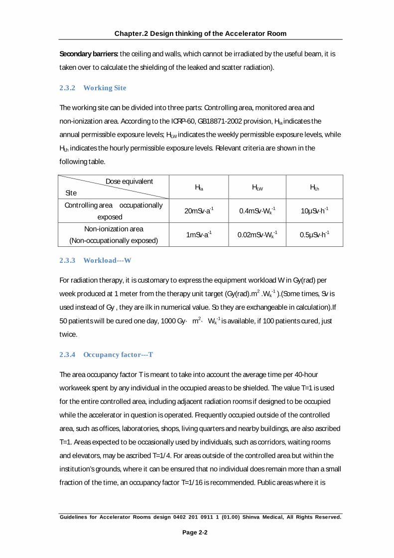
2.3.2 Working Site
The working site can be divided into three parts: Controlling area, monitored area and
non-ionization area. According to the ICRP-60, GB18871-2002 provision, Hla indicates the
annual permissible exposure levels; HLW indicates the weekly permissible exposure levels, while
HLh indicates the hourly permissible exposure levels. Relevant criteria are shown in the
following table.
Dose equivalent
Site Hla HLW HLh
Controlling area(occupationally
exposed) 20mSv·a-1 0.4mSv·Wk
-1 10μSv·h-1
Non-ionization area
(Non-occupationally exposed) 1mSv·a-1 0.02mSv·Wk
-1 0.5μSv·h-1
2.3.3 Workload---W
For radiation therapy, it is customary to express the equipment workload W in Gy(rad) per
week produced at 1 meter from the therapy unit target (Gy(rad).m2 .Wk-1 ).(Some times, Sv is
used instead of Gy , they are ilk in numerical value. So they are exchangeable in calculation).If
50 patients will be cured one day, 1000 Gy�m2�Wk-1 is available, if 100 patients cured, just
twice.
2.3.4 Occupancy factor---T
The area occupancy factor T is meant to take into account the average time per 40-hour
workweek spent by any individual in the occupied areas to be shielded. The value T=1 is used
for the entire controlled area, including adjacent radiation rooms if designed to be occupied
while the accelerator in question is operated. Frequently occupied outside of the controlled
area, such as offices, laboratories, shops, living quarters and nearby buildings, are also ascribed
T=1. Areas expected to be occasionally used by individuals, such as corridors, waiting rooms
and elevators, may be ascribed T=1/4. For areas outside of the controlled area but within the
institution’s grounds, where it can be ensured that no individual does remain more than a small
fraction of the time, an occupancy factor T=1/16 is recommended. Public areas where it is
Chapter.2 Design thinking of the Accelerator Room
Guidelines for Accelerator Rooms design 0402 201 0911 1 (01.00) Shinva Medical, All Rights Reserved.
Page 2-3
clearly unreasonable to expect that any individual would consistently linger more than, say, two
hours per week (such as streets, sidewalks, parking lots or lawns) may also be ascribed T=1/16.
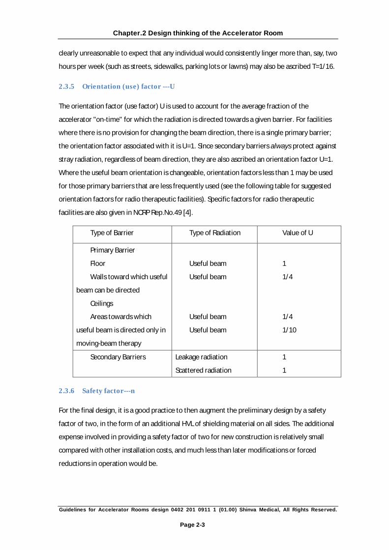
2.3.5 Orientation (use) factor ---U
The orientation factor (use factor) U is used to account for the average fraction of the
accelerator "on-time" for which the radiation is directed towards a given barrier. For facilities
where there is no provision for changing the beam direction, there is a single primary barrier;
the orientation factor associated with it is U=1. Since secondary barriers always protect against
stray radiation, regardless of beam direction, they are also ascribed an orientation factor U=1.
Where the useful beam orientation is changeable, orientation factors less than 1 may be used
for those primary barriers that are less frequently used (see the following table for suggested
orientation factors for radio therapeutic facilities). Specific factors for radio therapeutic
facilities are also given in NCRP Rep.No.49 [4].
Type of Barrier Type of Radiation Value of U
Primary Barrier
Floor
Walls toward which useful
beam can be directed
Ceilings
Areas towards which
useful beam is directed only in
moving-beam therapy
Useful beam
Useful beam
Useful beam
Useful beam
1
1/4
1/4
1/10
Secondary Barriers Leakage radiation
Scattered radiation
1
1
2.3.6 Safety factor---n
For the final design, it is a good practice to then augment the preliminary design by a safety
factor of two, in the form of an additional HVL of shielding material on all sides. The additional
expense involved in providing a safety factor of two for new construction is relatively small
compared with other installation costs, and much less than later modifications or forced
reductions in operation would be.

Chapter.2 Design thinking of the Accelerator Room
Guidelines for Accelerator Rooms design 0402 201 0911 1 (01.00) Shinva Medical, All Rights Reserved.
Page 2-4
2.4 Calculation of X-ray Shielding
2.4.1 Symbols explain
d: Distance between the target and the nearest point of the area to be protected (m);
d1: Distance between the target and nearest scattering object (m);
d2: Distance between scattering object and the nearest point of the area to be protected (m);
d3: Distance between backscattered radiation object and the nearest point of the area to be
protected (m);
S、S':S and S' stand for the areas on the concrete walls, ceilings or floors irradiated by the
useful beam and/or leaked beam visible from the nominal shielding point(m2);
K:Attenuation factor (dimensionless);
KL:Attenuation factor concerning of leaked radiation;
KS:Attenuation factor concerning of scatter radiation.
2.4.2 b. Primary shielding against the treatment beam
K=W(Sv·m2·Wk-1)·U·T·n/HLW(Sv·Wk
-1)d2(m2)
=W×U×T×n/ HLWd2
Parameters in the brackets have dimensions in the formulae, while U、T、n、K are
dimensionles.
2.4.3 Shielding of leakage radiation
We (manufacture) guarantee the criterion (the average leaked radiation should be constraint
under 0.1% of that in the axis of the useful beam) that the leakage at a reference point with a
beam stopper in the radiation head. Thus WL should be W/1000,
KL=WL(Sv·m2·Wk-1)·T·n/HLW(Sv·Wk
-1)d2(m2)=WL×T×n/ HLWd2
As medical accelerators discussed here, the dose of scatter radiation from patient and couch
faceplate should not exceed the leakage dose. Meanwhile, as scatter radiation is less
penetrating than the leakage radiation, it is mainly taken into account in the confirmation of
thickness of the secondary shielding.
Chapter.2 Design thinking of the Accelerator Room
Guidelines for Accelerator Rooms design 0402 201 0911 1 (01.00) Shinva Medical, All Rights Reserved.
Page 2-5
2.4.4 Shielding of scattered photons
Photons scattered by objects in the direct bremsstrahlung beam must be considered in the
calculation of shielding barrier thickness, as well as in the design of labyrinths and ducts. The
amount of radiation scattered is proportional to such factors as the radiation intensity incident
on the surface and the area of the surface irradiated, and it is inversely proportional to the
distance from the irradiated surface to the location in question. These factors are multiplied by
a dimensionless coefficientα, called the differential dose albedo, which depends on the
photon energy spectrum, the type of material irradiated, the angle of scattering, and the
orientation of the surface.
KS=(S�W+S'�WL)α/d12�d2
2�HLW�100
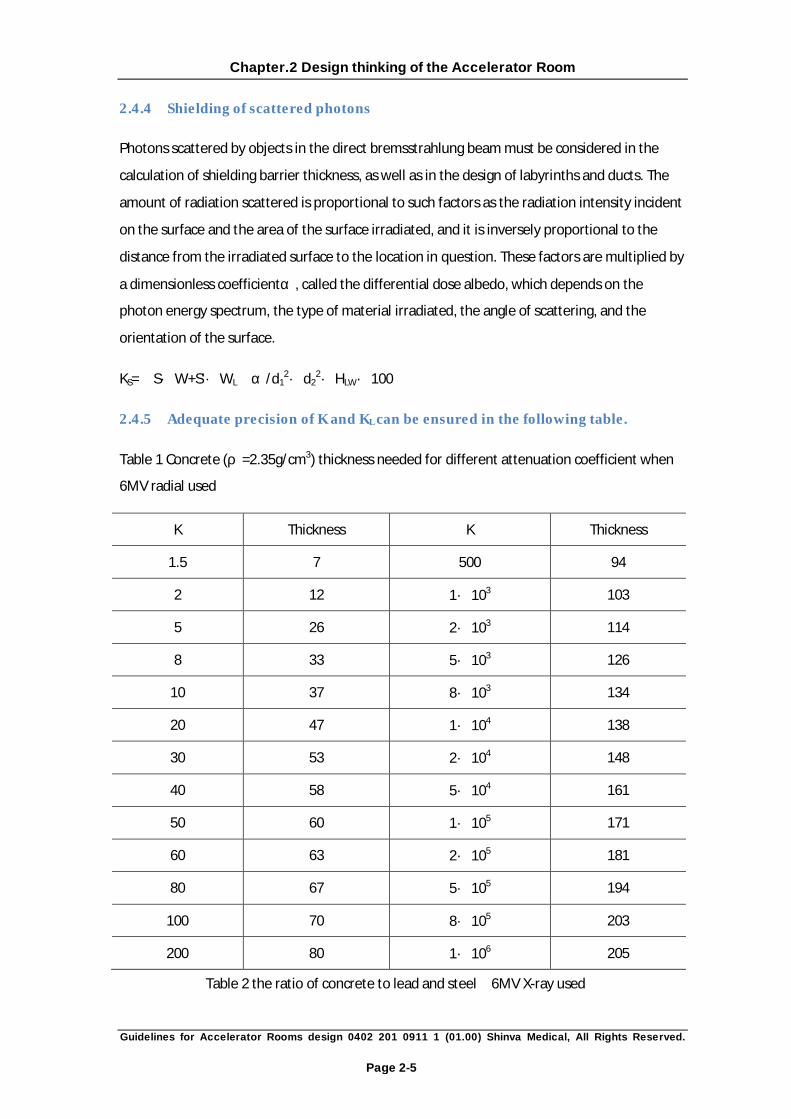
2.4.5 Adequate precision of K and KL can be ensured in the following table.
Table 1 Concrete (ρ=2.35g/cm3) thickness needed for different attenuation coefficient when
6MV radial used
K Thickness K Thickness
1.5 7 500 94
2 12 1�103 103
5 26 2�103 114
8 33 5�103 126
10 37 8�103 134
20 47 1�104 138
30 53 2�104 148
40 58 5�104 161
50 60 1�105 171
60 63 2�105 181
80 67 5�105 194
100 70 8�105 203
200 80 1�106 205
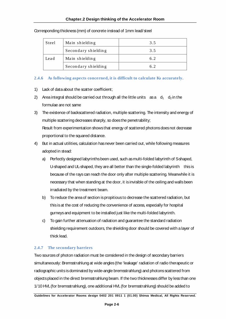
Table 2 the ratio of concrete to lead and steel(6MV X-ray used)
Chapter.2 Design thinking of the Accelerator Room
Guidelines for Accelerator Rooms design 0402 201 0911 1 (01.00) Shinva Medical, All Rights Reserved.
Page 2-6
Corresponding thickness (mm) of concrete instead of 1mm lead/steel
Steel Main shielding 3.5
Secondary shielding 3.5
Lead Main shielding 6.2
Secondary shielding 6.2
2.4.6 As following aspects concerned, it is difficult to calculate Ks accurately.
1) Lack of data about the scatter coefficient;
2) Area integral should be carried out through all the little units(as a,d1,d2 in the
formulae are not same);
3) The existence of backscattered radiation, multiple scattering. The intensity and energy of
multiple scattering decreases sharply, so does the penetrability;
Result from experimentation shows that energy of scattered photons does not decrease
proportional to the squared distance.
4) But in actual utilities, calculation has never been carried out, while following measures
adopted in stead:
a) Perfectly designed labyrinths been used, such as multi-folded labyrinth of S-shaped,
U-shaped and UL-shaped, they are all better than the single-folded labyrinth,this is
because of the rays can reach the door only after multiple scattering. Meanwhile it is
necessary that when standing at the door, it is invisible of the ceiling and walls been
irradiated by the treatment beam.
b) To reduce the area of section is propitious to decrease the scattered radiation, but
this is at the cost of reducing the convenience of access, especially for hospital
gurneys and equipment to be installed just like the multi-folded labyrinth.
c) To gain further attenuation of radiation and guarantee the standard radiation
shielding requirement outdoors, the shielding door should be covered with a layer of
thick lead.
2.4.7 The secondary barriers
Two sources of photon radiation must be considered in the design of secondary barriers
simultaneously: Bremsstrahlung at wide angles (the ‘leakage’ radiation of radio therapeutic or
radiographic units is dominated by wide-angle bremsstrahlung) and photons scattered from
objects placed in the direct bremsstrahlung beam. If the two thicknesses differ by less than one
1/10 HVL (for bremsstrahlung), one additional HVL (for bremsstrahlung) should be added to

Chapter.2 Design thinking of the Accelerator Room
Guidelines for Accelerator Rooms design 0402 201 0911 1 (01.00) Shinva Medical, All Rights Reserved.
Page 2-7
the calculated thickness. If they differ by more than one (including one) HVL, the bigger one
should be used.
2.4.8 Two viewpoints
There are two viewpoints international existed now. One side insists that the annual dose
equivalent of personnel should be decreased. While the opposite insists that small dose
radiation will do good to human health by enhancing the immunity ability. They drew this
conclusion on the basis of the facts from the last several decades. For example, the health
condition of the inhabitants who received small radiation from the A-bomb and the personnel
who engaged in A-bomb or nuclear energy study is better than the average.
2.4.9 Optimization in shielding:
When thick shielding is designed, heavy investment is needed;While thin shielding is
designed; the dose equivalent and the venture of health hazard will increase. The optimized
design can minimize the total expense of shielding and health damage. The dose equivalent
will not decrease much as expected when the thickness is added blindly. But if weak spots
(such as straight hole) exist in the design, the dose equivalent will increase sharply.

Chapter.3 Primitive Data of the Accelerator Facilities
Guidelines for Accelerator Rooms design 0402 201 0911 1 (01.00) Shinva Medical, All Rights Reserved.
Page 3-1
Chapter.3 Primitive Data of the Accelerator Facilities
Medical linac XHA600C radiates only one kind of X-ray.
1. This kind of X-ray has a continuous spectrum, energy of the peaks in the spectrum is 6MV
(that is to say, the energy of accelerated electron is 6MeV). SAD=100cm.
2. When 10cm×10cm irradiation field being used, the absorbed X-ray penetrability dosage
10cm under water at the nominal treatment distance (100cm of the useful beam) as
defined in IEC, its quantity is about (67±3) % of the dosemax.
3. At normal treatment distance (100cm), the nominal dosage absorbed is 2.5Gy/min. It is
possible that the new equipment will have a higher energy and output than this criterion.
On the safe case, 3Gy/min can be adopted into the shielding calculation.
4. At normal treatment distance (100cm), the max irradiation field is 40cm×40cm.
(primary-collimating angle of 2×13.9°can be adopted into the shielding calculation)
5. The gantry can revolve 370°around the main axis, and the direction of radiation beam is
changeable.
6. The max leakage dose should be constraint less than 0.1% of the main beam normally.
7. As this accelerator belongs to the low-energy series, the neutron effect and induced
radiation can be ignored in the shielding calculation, as well as the radiation from the
oxygen and nitrogen been activated.

Chapter.4 The Overall Design Requirement of Accelerator Room
Guidelines for Accelerator Rooms design 0402 201 0911 1 (01.00) Shinva Medical, All Rights Reserved.
Page 4-1
Chapter.4 The Overall Design Requirement of Accelerator
Room
4.1 Structure and layout
1. Because of the weight of shielding barriers, a ground-level location is preferred for
radiation facilities. If this is not possible/available, construction must be given to the
problem of structural support. Its space should be no less than 36 m2. Basement is not
preferred here, because it is necessary to transport in the accelerator before the building
is completely constructed if such a room is chosen. Meanwhile, the damp will corrupt the
machine stored in such environment in a long term, and it is inconvenient to update the
equipment in one or two decades.
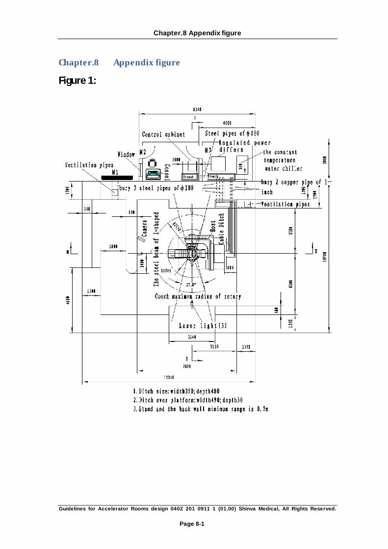
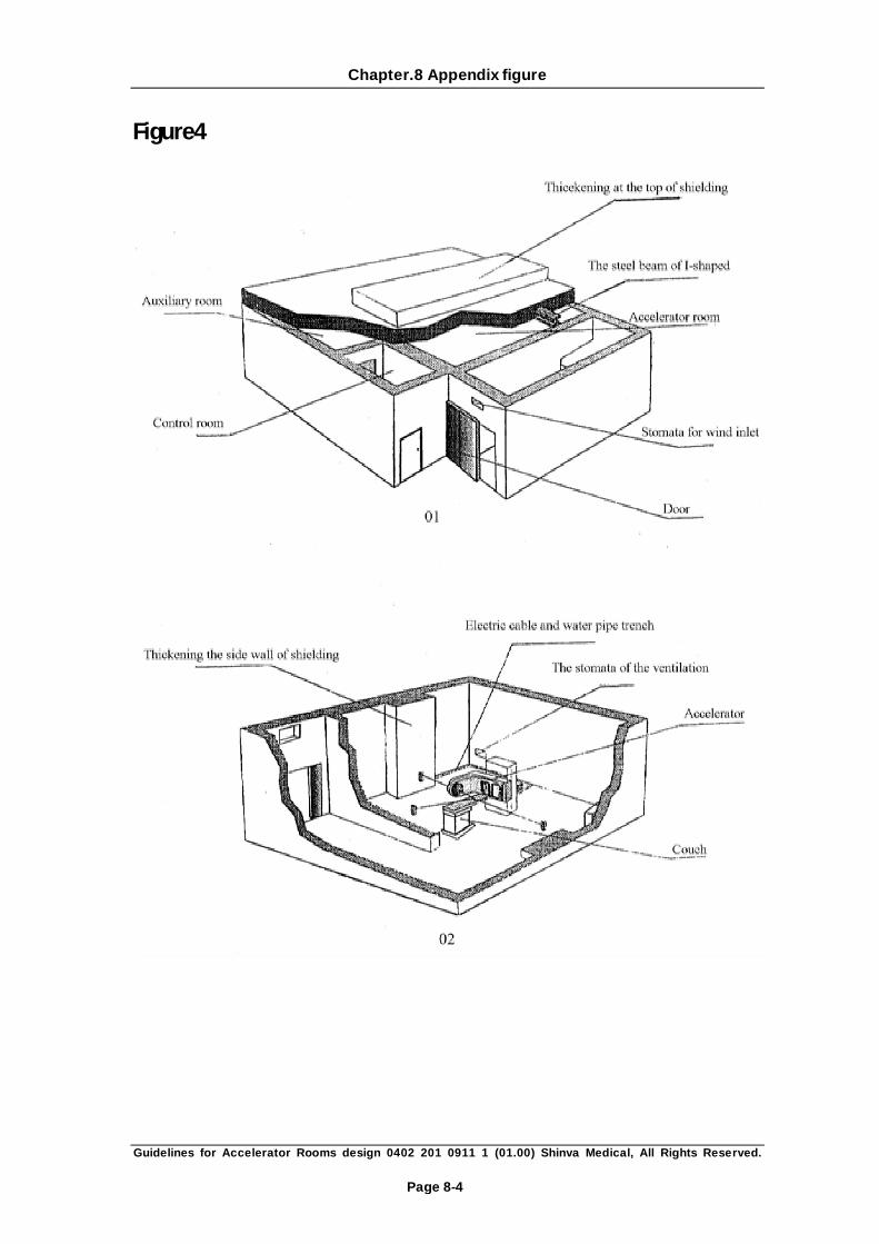
2. To satisfy the normal work of the accelerator need three rooms, treatment rooms, a
control room and auxiliary engine room. Room layout and size of the main planning and
design; see Figure 1 (room layout map, Page19). One treatment room area has been taken
into account total body irradiation method needs the control room area of not less than
13 m2; auxiliary engine room should be not less than 10 m2. At the same time users in the
design room should also consider simulator rooms, radiation physics room, waiting room,
office, examination room, maintenance work, and assorted space settings
4.2 Shielding requirements (see P19-21 Figure 1, 2, 3)
1. Careful mixing and pouring of close-grained concrete are important to ensure uniformity
and to prevent settling of the high-density filler. No cavum and gap should exist, and the
density should be no less than 2.35g/cm3. Checking-up work should be carried
occasionally during the constructing period, and pre-set pipes should not be ignored.
2. None pipeline is permitted to pass through the shielding straightly. Compensating
measures should be carried out in weak spots where shielding ability is decreased by the
pipelines for ventilations and cables.
3. Windows could not to be designed in the treatment room, neither at other places where
shielding ability may be decreased.
4. The shielding door should be larger than the door cavity, so that the joints (no less than
100mm on one side) between walls and door are adequate to reduce the leakage of
radiation.
Chapter.4 The Overall Design Requirement of Accelerator Room
Guidelines for Accelerator Rooms design 0402 201 0911 1 (01.00) Shinva Medical, All Rights Reserved.
Page 4-2
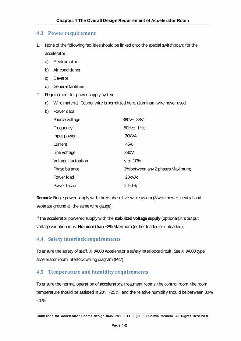
4.3 Power requirement
1. None of the following facilities should be linked onto the special switchboard for the
accelerator:
a) Electromotor
b) Air conditioner
c) Elevator
d) General facilities
2. Requirement for power supply system
a) Wire material: Copper wire is permitted here, aluminum wire never used.
b) Power data:
Source voltage 380V±38V;
Frequency 50Hz±1Hz;
Input power 30kVA;
Current 45A;
Line voltage 380V;
Voltage fluctuation ≤±10%;
Phase balance 3% between any 2 phases Maximum;
Power load 20kVA;
Power factor ≥90%;
Remark: Single power supply with three-phase five-wire system (3 wire power, neutral and
separate ground all the same wire gauge).
If the accelerator powered supply with the stabilized voltage supply (optional),it’s output
voltage variation must No more than ±3% Maximum (either loaded or unloaded);
4.4 Safety interlock requirements
To ensure the safety of staff, XHA600 Accelerator a safety interlocks circuit. See XHA600 type
accelerator room interlock wiring diagram (P27).
4.5 Temperature and humidity requirements
To ensure the normal operation of accelerators, treatment rooms, the control room, the room
temperature should be assisted in 20 ℃ -25 , and the relative humidity should be between 30% ℃
-75%.

Chapter.4 The Overall Design Requirement of Accelerator Room
Guidelines for Accelerator Rooms design 0402 201 0911 1 (01.00) Shinva Medical, All Rights Reserved.
Page 4-3
4.6 Ventilation requirements
When the accelerator is routinely running, the production of bit toxic gases such as ozone and
nitrogen oxide is observed (without radioactive gases). And seldom SF6 gas will be produced
during the repairing of microwave system. If the accelerator sparks frequently, toxic gas will be
decomposed from SF6 by the arc, the gas must be discharged by the ventilating system.
4.7 Grounding safety requirements
A fixed grounding system separated from neutral should be offered to link the ground directly
and perfectly.
1. The resistance of the grounding system should be no more than 0.4Ω.
2. Ground wire:The ground wire must be an insulated, stranded, copper conductor of the
same wire gauge and type as the phases and neutral, continuous in length, stemming from
the ground side of the neutral to ground bond point of the required conditioning
step-down transformers (the separately derived source)
3. The importance of a single power and ground source for microprocessor controlled
therapy equipment cannot be over-emphasized. Multi ground paths or events from other
power source are easily imported into microprocessor equipment by data cables and
control circuits that interconnect equipment subsystems.
4. A copper bolt (M10) should be welded on the linkable end of the grounding system, and
this end should be stretched to the L-shaped groove behind the base of accelerator.

Chapter.5 The Specific Design for Accelerator Room
Guidelines for Accelerator Rooms design 0402 201 0911 1 (01.00) Shinva Medical, All Rights Reserved.
Page 5-1
Chapter.5 The Specific Design for Accelerator Room
5.1 Treatment room (see Perspective Room P22-23)
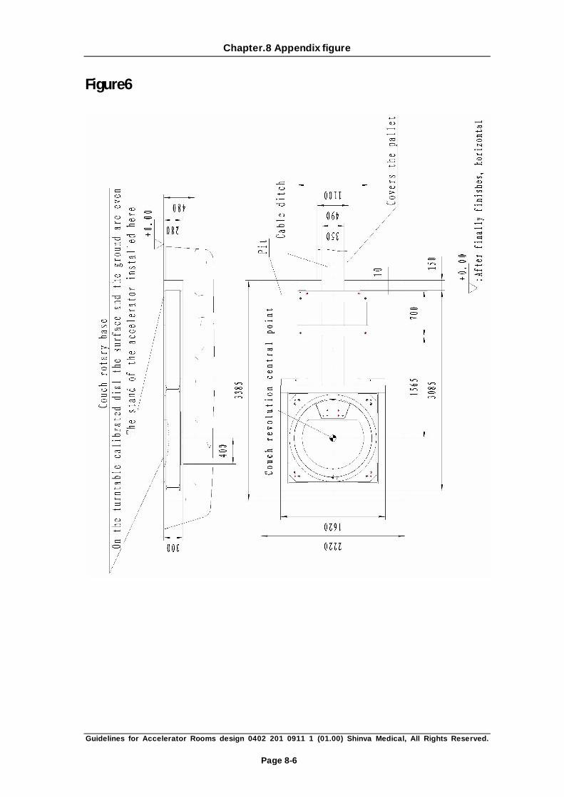
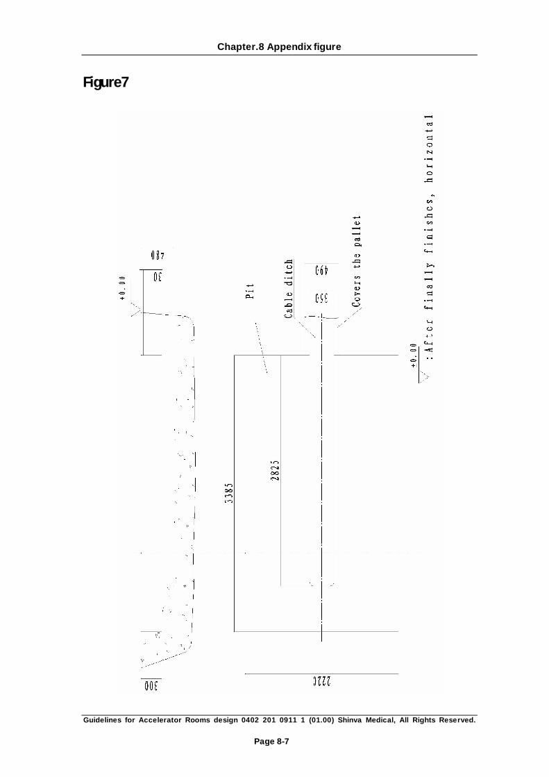
5.1.1 Pit design
1. Figure of delve/pit and foundation of the accelerator(see P20)
2. Figure of delve and foundation for the main part of accelerator(see P21)
3. Thickness of base for accelerator in the treatment room should be no less than 200mm,
the compressive strength should behigher than 20MN/m2(2800pound/inch2), and finally
the horizontal error on the cater corner should be limited in the range from -5mm to
+5mm.
4. Base of the accelerator (offered by Inhaul) should be buried when the concrete floor is
poured in the treatment room. The location of base in the pit and the eventual orientation
work should be supervised by the installation engineers from Inhaul, and assisted by the
Porters employed by customer. The sunken sits of the pit should be poured with
concrete after the base is located and the horizontal error is guaranteed.
5. As to the ordinary concrete(2.35g/cm3), the shortest maintenance period should be
seven days, and the compressive strength will reach 141kg/cm2.
6. Within the scope of 1800mm around the center, the evenness error between floor and
the top of the base should be controlled in the range from -3mm to +3mm.
5.1.2 Labyrinth, the protective doors and floors Design
1. The height (more than 2.5m) and width (more than 1.8m) of labyrinths and shielding door
should be convenient for the transportation and inlet of accelerator. So does the path
between the unpacking place and the treatment room.
2. Experienced Porters are required to inspect on-site with a transportation sample to
make sure that empty space is preserved for transportation. The transportation sample
should be able to pass through the labyrinths and not touch the walls. To in-let the moving
work pieces conveniently, the floor should be designed to bear the heaviest loads
contemplated.
3. Figure of the main part's transportation route (page 32)
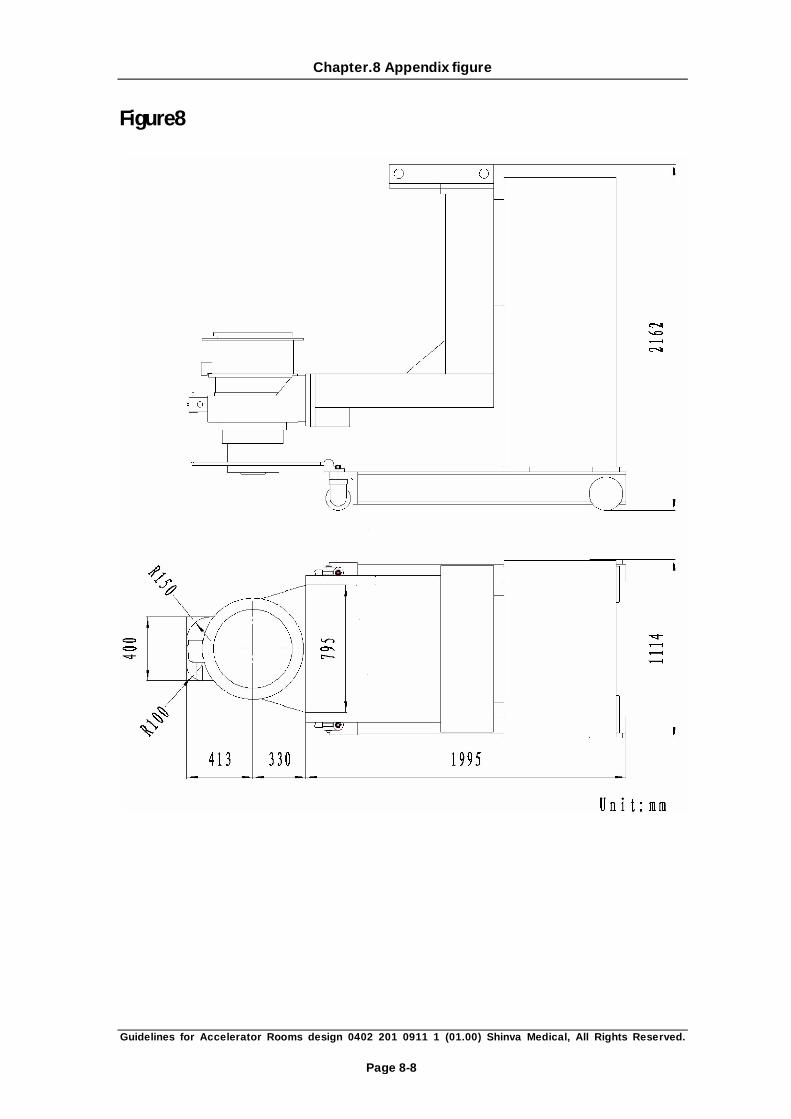
4. Figure of the profile of the transportation dolly (page 26)

Chapter.5 The Specific Design for Accelerator Room
Guidelines for Accelerator Rooms design 0402 201 0911 1 (01.00) Shinva Medical, All Rights Reserved.
Page 5-2
5. As the machine is placed on the dolly and pushed into the room by labor power, an
eyebolt of 10-ton capacity for traction at the labyrinth corners should be designed on the
walls opposite the labyrinths gate so that the machine can be moved in conveniently.( see
page31 A-A)
6. An interlock switch should be installed on the shielding door so that the beams can only
be produced when the door is closed and if any person breaks into the room, the
irradiation will terminate at once. The interlock should be installed along with the door;
two wires placed through the buried cable conduit (See room online support facilities
threads pipeline maps, P28) are used to connect the “normal open”. These wires should
be stretched to the groove and 3 meters lengthened lines are needed for the future
linkage up to TB1-7,8 on the main board by our engineers.
7. Protective doors protective capacity of not less than 6 mm lead equivalent. Proposed the
installation of doors manually switching devices and infrared devices.
8. Two lights over the door should be installed, a green one for warning of irradiation
"READY" and a red one for warning of irradiation "ON". three wires should be placed
through the conduit(See room online support facilities threads pipeline maps, P28)and
stretched to the cable groove under the main body, three meters' extra lengthened lines
should be prepared for the linkage to TB1-10、11、12 on the main board.
5.1.3 Cable Ditch design (See P19 treatment room layout)
1. Cable Ditch: Cable conduits designed in the auxiliary room, control room and treatment
room are used in laying the cable lines or water pipes among the rooms.
2. Cable ducts: Three pipes larger than φ100 in diameter should be buried between the
treatment room and control room (cable conduits nearside are preferred to be
connected). Oblique (in the horizontal plane) pipelines are preferred to reduce the
scattered radiation.
3. Bending radius 6 times of the diameter is commended to use for cable pipes if any pipe
needed to be bended in laying. The total bending angle of the cable pipe should not
exceed 270°。
4. Temporary cable pipes for dosimeter and three-dimension water tank are preferred
between the treatment room and control room to avoid blending with the permanent
cable conduits.
5. A copper (or stainless steel) pipe of 1-inch diameter from the water chiller in the auxiliary
room to the rear face of the accelerator should be buried in advance so that the inflow

Chapter.5 The Specific Design for Accelerator Room
Guidelines for Accelerator Rooms design 0402 201 0911 1 (01.00) Shinva Medical, All Rights Reserved.
Page 5-3
and outflow of constant temperature water can be guaranteed, U-shaped is preferred
here. To minish the radiation, the lower part should be buried underground. Treatment of
indoor plumbing to increase ball valves, fittings for ZG1 "in the thread.
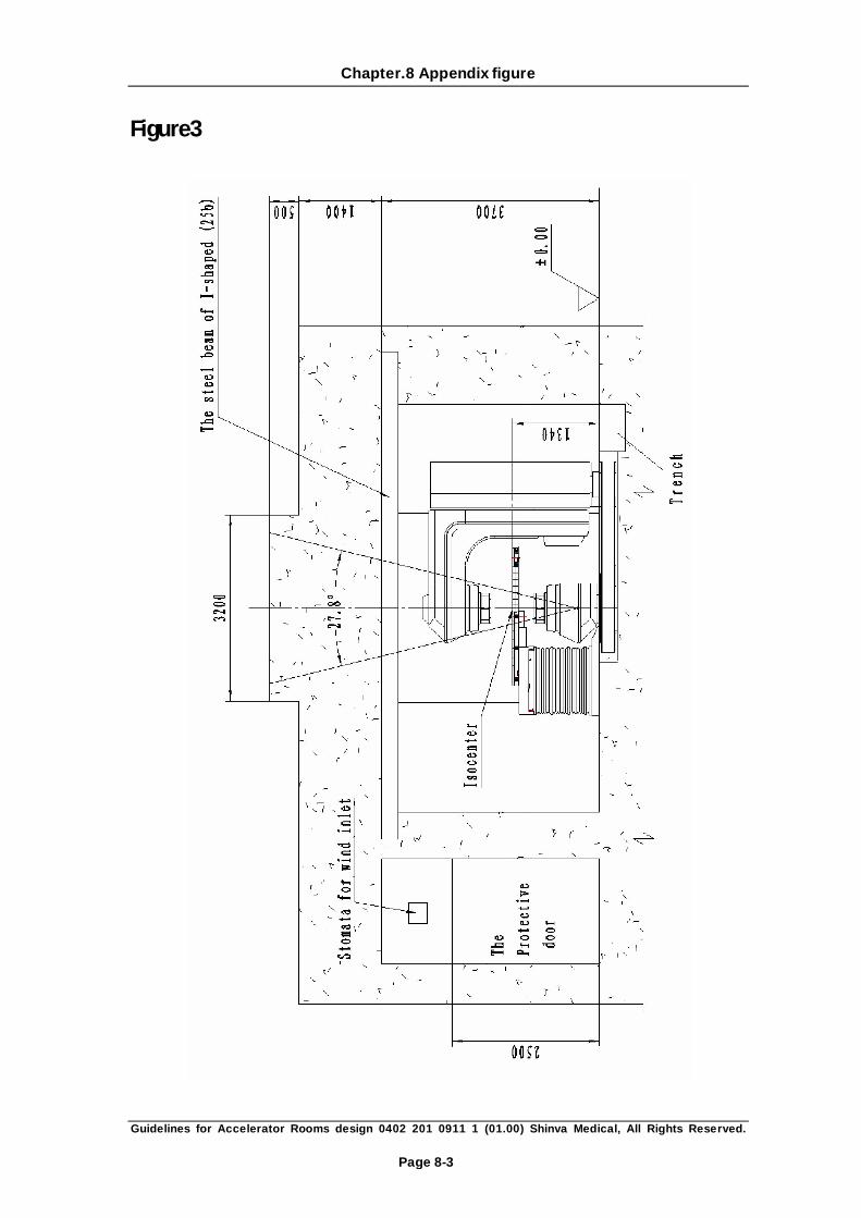
5.1.4 Crane and crane beam design (see room elevation, P20)
A steel beam of I-shaped (25b) should be placed over the accelerator and should be across the
axis of the gantry. A railed manual crane and a two-ton manual elevator can be installed on the
beam so that it can be convenient to install and maintain the machine. The crane and elevator
is preferred to preserve at the original place for later maintenance.
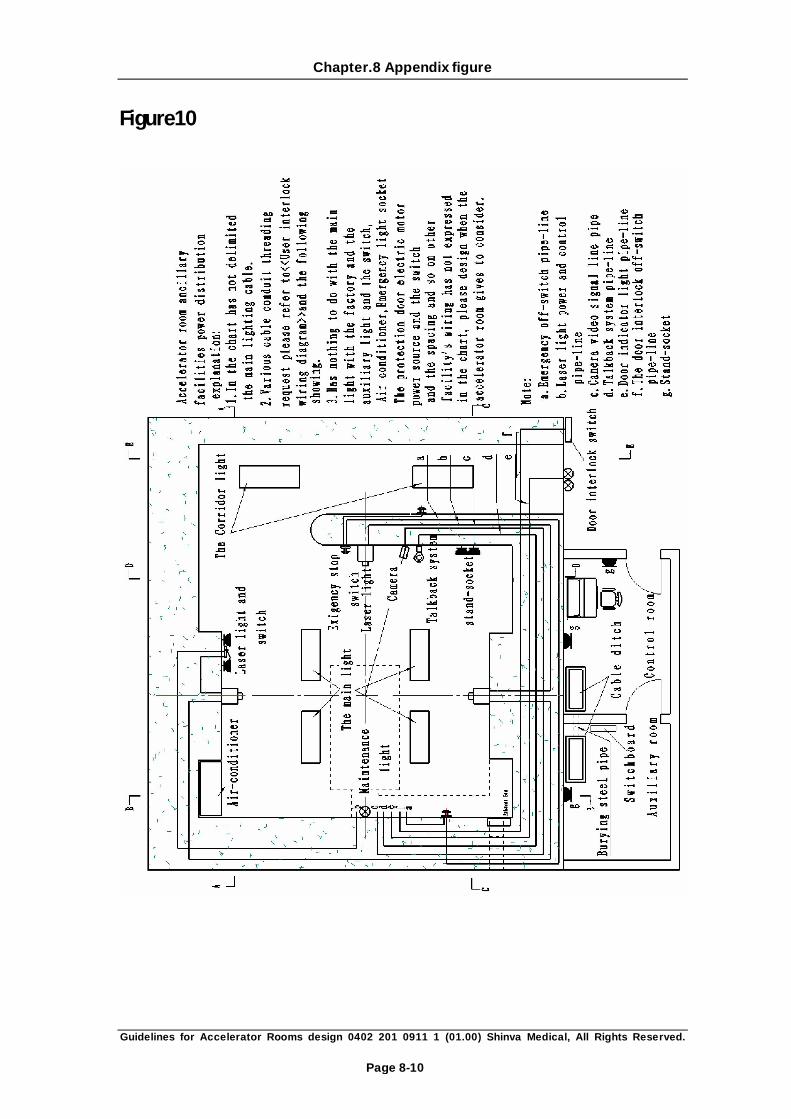
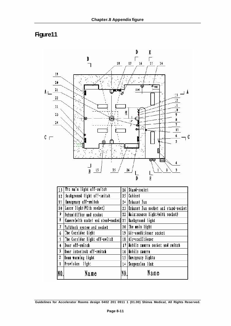
5.1.5 Lighting System
Respectively with the main light, background light, emergency light, maintenance light, the
corridor lights, and other five lights. In the accurate patient positioning process, lights in the
treatment room should be dimmed down so that the projection of field lamp and range finder
can be observed clearly. That is to say when is on, the field lamp and range finder should be
shut off and when the process is finished, they reset by themselves. Down-leads should be
placed through the conduit (not marked on the figure, it can be sketched by customer
accordingly) and stretched to the cable groove under the main body, three meters' extra
lengthened lines should be prepared for the linkage to TB1-3、4 on the main board.
5.1.6 The design of the ventilation system
1. The stomata of the ventilation should be placed far from the labyrinths. (see I-I room
elevation P20) As the specific gravity of ozone is larger than average, the stomata of
the ventilation should be as close as possible to the floor. The pipelines of ventilation
should be configured as labyrinths, with the biggest section area no less than 0.25m2。An
air pump is necessary at the stomata of the ventilation on the outside of the treatment
room. The capacity of the turbine should be able to guarantee the lowest command of air
changes of the treatment room 3~4 times in one hour in routine running. Relevant
compensation should be made at the places on the walls (or roof) where shielding ability
is attenuated. Wire netting should be added on the stomata to keep rats from entering
the rooms.
2. Stomata for wind inlet should be designed near the labyrinth gate, on the roof or above
the walls over the gate.(see II-II Room Elevation P27)。To constraint the radiation at the
minimum dose in the reachable area, the pipelines should be installed as high as possible.

Chapter.5 The Specific Design for Accelerator Room
Guidelines for Accelerator Rooms design 0402 201 0911 1 (01.00) Shinva Medical, All Rights Reserved.
Page 5-4
In the design of ventilation the section area (no more than 0.25m2) through the walls
should be minimized. Pipelines for wind inlet should be designed as labyrinth-shaped.
Relevant compensation should be made at weak spots on the walls (or roof) where
shielding ability is decreased by wind inlet pipes.
3. Stomata for wind inlet should be able to filter most particles whose diameter is larger than
10μm.
5.1.7 Heating and dehumidification Design
1. The proposed allocation of the treatment room air conditioners, dehumidifiers. To
maintain the temperature at 20℃ to 25℃, and the relative humidity is 30% -75%. Not
only patients feel comfortable, and it is not overheating and equipment too wet.
2. Room when planning the construction of the air-conditioning installation, embedded
good corresponding pipeline.
5.1.8 Other ancillary equipment (see Figure P29 to P32)
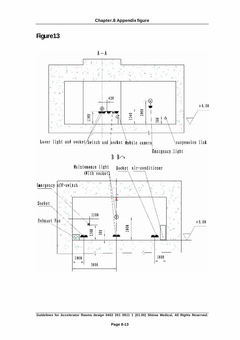
5.1.8.1 Laser positioning lights (optional):
Two on opposite walls (1340mm from finished floor) and a third one high (typically 2300mm
from finished floor) on the wall at the target end of the linac, project a vertical fan beam
through the gantry axis and all the three through isocenter. Three electrical outlets of 220V
power supply should be prepared, two of them (on the side walls) be placed 1.1m from the
finished floor and the third one 2m. One switch 1.3m from finished floor for controlling of
these lamps should be placed on the side wall close to the labyrinth and the down lead
stretched to the fossa under the main body with a cable conduit, just like the diagram
illustrates. And 3 meters lengthened lines should be prepared for future installation, they will
be linked up to TB1-1, 2 on the main board.
5.1.8.2 Emergency off-switches:
Beyond the emergency off-switches on couch, consol and stand,1--3 emergency off-switches
should be installed on proper places easy to touch in the treatment room and labyrinths(we
offer one at the booking time, others should be bought by customers themselves).They can
shut off the beam and relevant movements, but the following should never be shut off
emergently: the motor used for driving the shielding door, lamps in the treatment room, and
interlocks for safety cases. The emergency off-switches should be distinguished clearly and
easily buttoned, but not easily touched involuntary, nor should it be reset automatically. When

Chapter.5 The Specific Design for Accelerator Room
Guidelines for Accelerator Rooms design 0402 201 0911 1 (01.00) Shinva Medical, All Rights Reserved.
Page 5-5
several emergencies off-switches are used, they should be arranged in series. cable conduit
should be buried in advance during the capital construction (figure d), lines linked up and
switch installed (1.3m above the ground),two wires should be placed through the
conduit(figure e)and stretched to the cable groove under the main body, three meters' extra
lengthened lines should be prepared for the linkage to TB1-5、6 on the main board.
5.1.8.3 Camera (optional):
Best visual field should be ensured when the pickup camera is installed(normally located above
and at an angle of approximately 15° off the gantry axis of the accelerator, last places should
be ascertained according to the actual case), meanwhile, camera lens should be beyond the
irradiation scope of useful beam(because of the dimness of lens under irradiation).Sockets for
video information should be installed 2.5m from finished floor, and a cable conduit placed
through the groove (reference the diagram a, P28) and towards the monitor on the consol
table. Power sockets of 220V should be offered in the treatment room, just near the sockets
for video at 2.5m from finished floor.
5.1.8.4 Talkback System (optional):
Sockets for microphone and buzzer should be installed 2 meters from finished floor, and a
cable conduit for video wire be buried towards the fosse in the wall (reference to the diagram
d,P28) with a video wire inside. The wire will be linked up to an amplifier on the consol table.
5.1.8.5 Emergency lights (optional see P31A-A):
A set of emergency lamps should be installed in the treatment room; another set should be
installed in the labyrinths and consol area so that the patient can be moved away in case of
emergency shutoff of power.
5.1.8.6 Shelves or cabinets for storage (prepared by customer)
Shinva Medical recommends that users produce corresponding indoor lockers (planes) for the
storage accessories and other commonly used materials.
Accessories offered by Shinva Medical:
1 shelf for accessories (dimensions: diameter=480mm, height=175mm; maximum weight
=3.8kg)
1 appendix bracket (dimension: diameter=475mm, height=110mm; maximum weight =3kg)
4 brackets for lead stopper (dimension: 300mm×300mm×6mm);
Chapter.5 The Specific Design for Accelerator Room
Guidelines for Accelerator Rooms design 0402 201 0911 1 (01.00) Shinva Medical, All Rights Reserved.
Page 5-6
4 wedge filters (max dimension: 290mm×290mm×53mm/per; maximum weight =6.6kg)
13 (or 48) lead stopper (height=80mm;maximum weight =3.5kg)
1 isocenter displaying system (maximum weight =4.8kg)
Other materials in common use:
Coverlid, gauze, chair, mirror, rack for clothes, pedal,waste bin, spare parts and servicing
tools, plotting paper, marker for films, distilled water, dosimeter, flexible litter, film cabinet,
cushions and brackets for location use, gauging tools such as plane ruler, all kinds canisters for
irradiation shadow and suitable shaped lead blocks, dolly for holding the films, dolly for oxygen
vase, platform for total-body radiotherapy.
5.1.8.7 Stand-socket
Several power sockets of 220V (see P28) should be installed 30cm from the finished floor in the
treatment room,consol room and auxiliary room; they are used for future repair or other
purposes. Two power sockets on each wall are preferred.
5.1.9 Fire facilities
Fire alarm is preferred here but not water extinguisher.
5.2 Control room
1. Control room should be as close as possible to the entrance to the treatment rooms, the
best equipment Lade-window, with easy access and monitoring to prevent outsiders
entered.
2. Recommendations in the control room to install direct dial telephone, to facilitate
inspection accelerator Xinhua operating parameters and maintenance and
troubleshooting guide.
3. The proposed allocation of the control room air-conditioners, dehumidifiers. To maintain
the temperature at 20℃ to 25℃, and the relative humidity is 30% -75%. Do not forget
that for air conditioning pipe.
4. Pre-digging cable trenches, size finalized by the user. Console to the accelerator even for
the internal standard cable length of 18 m.
Chapter.5 The Specific Design for Accelerator Room
Guidelines for Accelerator Rooms design 0402 201 0911 1 (01.00) Shinva Medical, All Rights Reserved.
Page 5-7
5.3 Auxiliary Room
1. A constant temperature water chiller in the auxiliary room offers constant temperature
water. The unit for the standard configuration of water-cooled. If water-cooling system
chosen, two 5-meter long pipes of 20mm diameter are offered for the peripheral
water-circulation system by Xinhua Medical. Special tap water pipe and sewer should be
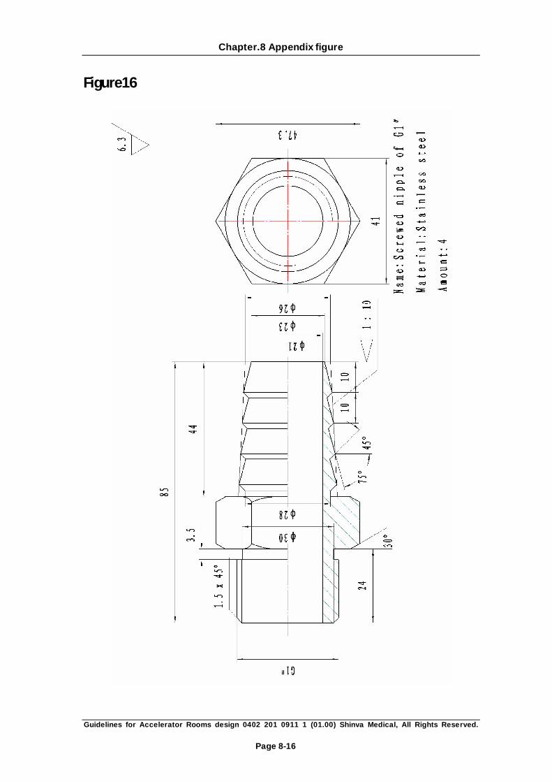
prepared in the auxiliary room, and a ZG3/4″screwed nipple or a 90°elbow nipple is
needed for the pipe nipples. Xinhua XHA600 Accelerator Unit of the water mains between
the accelerator and the largest pipeline length of 25 m.
2. Ditch-digging cable (see Figure room layout plans Page19), the size of the final set by the
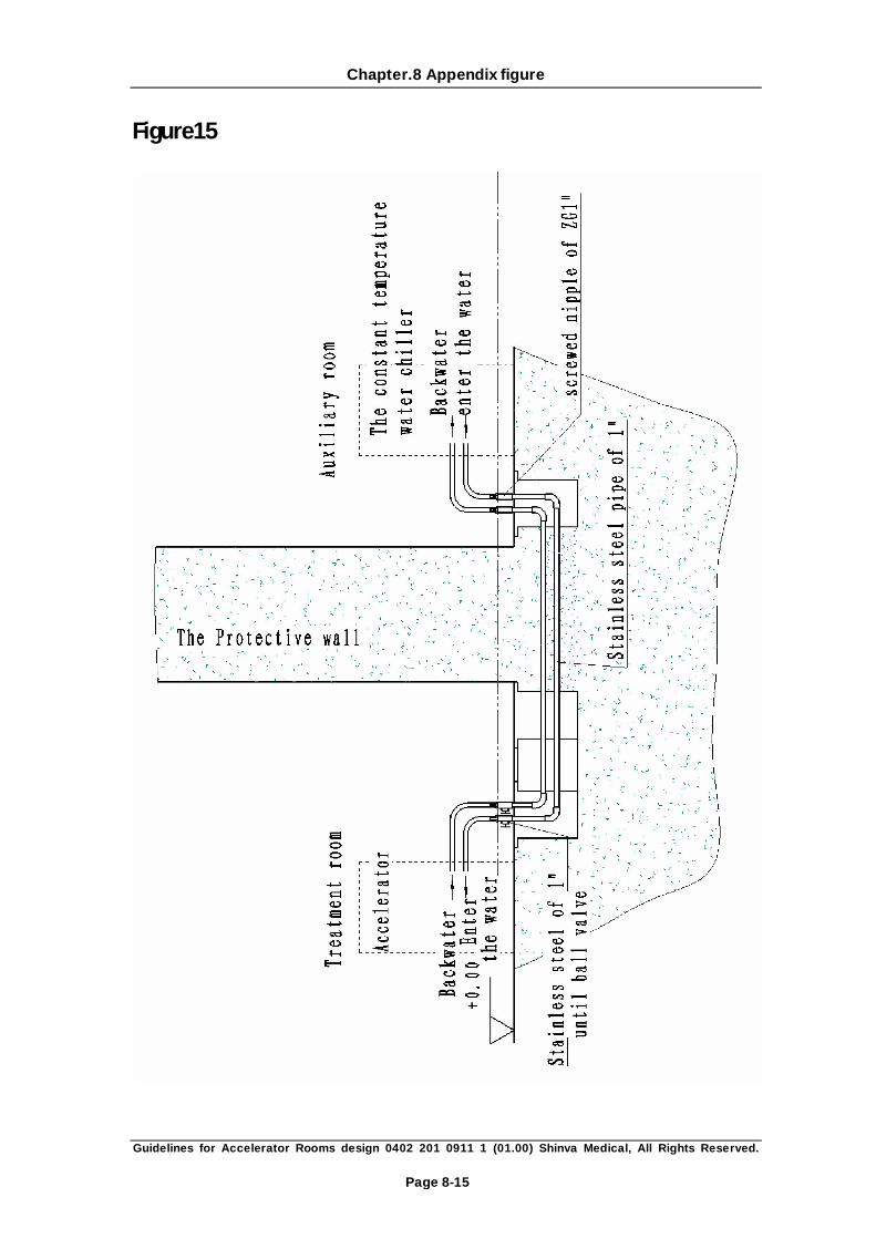
user. A copper (or stainless steel) pipe of 1-inch diameter from the water chiller in the
auxiliary room to the rear face of the accelerator should be buried in advance so that the
inflow and outflow of constant temperature water can be guaranteed, U-shaped is
preferred here(see P33). To minish the radiation, the lower part should be buried
underground. Two copper (or stainless steel) pipes should be linked up with screw thread
of ZG1″at the ends, and global valve used in the treatment room, finally outer screwed
nipple of ZG1″or a 90°elbow screwed nipple (to link the outer screwed nipple of G1″
offered by Xinhua Medical) used in the linkage at the end of auxiliary room (see P34). The
inner screw thread of ZG1″should be left and sealed so that it can be easily linked with
the special nipple of water/hose of 1–inch diameter in the installing process. Two black
latex pipes of 6 meters are offered to the treatment room by Xinhua Medical, and two 1″
hoses of 6 meters to the auxiliary room. The customer should take responsibility to reset
the pipes at the places where water pipes available with elbows and stainless steel pipe. In
order to keep the cleanness of the inner side of the pipes, clean parts such as pipes and
valves are used in the installation。The position and direction of the nipple should be
convenient to link in the water pipe of the accelerator.
3. Auxiliary room dedicated to a water faucet and the leaking, the leak must be at the lowest
point, in order to ensure full and timely water discharge.
4. Power distribution disk accelerator installed in the auxiliary engine room and the control
room wall, it is perpendicular to the cables through walls through the ditch.

Chapter.6 Packing list
Guidelines for Accelerator Rooms design 0402 201 0911 1 (01.00) Shinva Medical, All Rights Reserved.
Page 6-1
Chapter.6 Packing list
Case
No. Dimensions (cm)
Gross weight
(kg)
Net weight
(kg) Main components
1 298x164x240 4568 4183 Main body, booster, toolbox
2 228x150x160 317 87 Fiberglass cover, rear cover of
gantry, gantry top
3 264x68x100 257 158
Couch frame, couch axis. Couch
faceplate, frontal cover, side door,
and laser positioning lights.
Emergency switches, door switch,
door gemel
4 168x78x93 977 893 Couch body
5 119.5x126x50 970 717 Couch base. Joint fastener.
Staff gauge
6 142x72x99 2052 1977 Counter weight
7 140x83x101 210 154 Modulator
8 90x68x98 162 116 Console
9 107x63x87
Brackets for accessories, appendix
brackets, magnetron,
wedges.CX1159.5C22grid glow tube,
bracket (drilled or not) for lead
stopper
10 Optional parts 320 270 Power regulator
11 142x125x132 362 285 Computer, monitor, interphones,
emergency switches
12 Optional parts Constant temperature water system
13 800 660 Linac base
Remark: If the type of the constant temperature chiller and regulated power differs, the
dimension and weight of each will vary correspondingly.

Chapter.7 Appendix
Guidelines for Accelerator Rooms design 0402 201 0911 1 (01.00) Shinva Medical, All Rights Reserved.
Page 7-1
Chapter.7 Appendix
1. IEC Medical Electrical Equipment. Part 2: Particular requirements for safety of medical
electron accelerators in the range 1 MeV to 50 MeV. Publication 601-2-1 Section five:
Radiation requirements.
2. IEC Report, IEC977, Medical Electron Accelerators. Guidelines for functional performance
characteristics, 1989.
3. IEC Report, IEC976, Medical Electron Equipment. Medical electron accelerators-Functional
performance characteristics, 1989.
4. NCPP Report No.39: Basic radiation protection criteria, National Council on Radiation
Protection and Measurements, Bethesda, MD, 1979, p145.
5. NCPP Report No.49: Structural shielding design and evaluation for medical use of x-rays
and gamma rays of energies up to 10 MeV, National Council on Radiation Protection and
Measurements, Bethesda, MD, 1976, p126.
6. NCPP Report No.51: Radiation protection design guidelines for 01-100 MeV particle
accelerator facilities, National Council on Radiation Protection and Measurements,
Bethesda, MD, 1977, p159.
7. NCPP Report No.88: Radiation alarms and access control systems. National Council on
Radiation Protection and Measurements, Bethesda, MD, 1986, p81.
8. DeSTAEBLER, H., JENKINS, T.M.., NELSON, W.R., “shielding and radiation”, the Standard
Two-Mile Accelerator (NEAL, R.B., Ed), Ch.26, Benjamin, NEW York (1968).
9. ICRP Publication 73.Radiological protection and safety in medicine, International
Commission on Radiological Protection. Pergamon, Oxford, 1996.
Chapter.8 Appendix figure
Guidelines for Accelerator Rooms design 0402 201 0911 1 (01.00) Shinva Medical, All Rights Reserved.
Page 8-1
Chapter.8 Appendix figure
Figure 1:

Chapter.8 Appendix figure
Guidelines for Accelerator Rooms design 0402 201 0911 1 (01.00) Shinva Medical, All Rights Reserved.
Page 8-2
Figure2
Chapter.8 Appendix figure
Guidelines for Accelerator Rooms design 0402 201 0911 1 (01.00) Shinva Medical, All Rights Reserved.
Page 8-3
Figure3
Chapter.8 Appendix figure
Guidelines for Accelerator Rooms design 0402 201 0911 1 (01.00) Shinva Medical, All Rights Reserved.
Page 8-4
Figure4

Chapter.8 Appendix figure
Guidelines for Accelerator Rooms design 0402 201 0911 1 (01.00) Shinva Medical, All Rights Reserved.
Page 8-5
Figure5
Chapter.8 Appendix figure
Guidelines for Accelerator Rooms design 0402 201 0911 1 (01.00) Shinva Medical, All Rights Reserved.
Page 8-6
Figure6
Chapter.8 Appendix figure
Guidelines for Accelerator Rooms design 0402 201 0911 1 (01.00) Shinva Medical, All Rights Reserved.
Page 8-7
Figure7
Chapter.8 Appendix figure
Guidelines for Accelerator Rooms design 0402 201 0911 1 (01.00) Shinva Medical, All Rights Reserved.
Page 8-8
Figure8

Chapter.8 Appendix figure
Guidelines for Accelerator Rooms design 0402 201 0911 1 (01.00) Shinva Medical, All Rights Reserved.
Page 8-9
Figure9
Chapter.8 Appendix figure
Guidelines for Accelerator Rooms design 0402 201 0911 1 (01.00) Shinva Medical, All Rights Reserved.
Page 8-10
Figure10
Chapter.8 Appendix figure
Guidelines for Accelerator Rooms design 0402 201 0911 1 (01.00) Shinva Medical, All Rights Reserved.
Page 8-11
Figure11

Chapter.8 Appendix figure
Guidelines for Accelerator Rooms design 0402 201 0911 1 (01.00) Shinva Medical, All Rights Reserved.
Page 8-12
Figure12
Chapter.8 Appendix figure
Guidelines for Accelerator Rooms design 0402 201 0911 1 (01.00) Shinva Medical, All Rights Reserved.
Page 8-13
Figure13

Chapter.8 Appendix figure
Guidelines for Accelerator Rooms design 0402 201 0911 1 (01.00) Shinva Medical, All Rights Reserved.
Page 8-14
Figure14
Chapter.8 Appendix figure
Guidelines for Accelerator Rooms design 0402 201 0911 1 (01.00) Shinva Medical, All Rights Reserved.
Page 8-15
Figure15
Chapter.8 Appendix figure
Guidelines for Accelerator Rooms design 0402 201 0911 1 (01.00) Shinva Medical, All Rights Reserved.
Page 8-16
Figure16

Chapter.8 Appendix figure
Guidelines for Accelerator Rooms design 0402 201 0911 1 (01.00) Shinva Medical, All Rights Reserved.
Page 8-17
Figure17

Telephone: 0086-533-3587719 0086-533-3587720
Fax: 0086-533-3587722
Post: 255086
Company: Shinva Medical Instrument co., Ltd
Address: Shinva Medical Scientific Zone, Zibo New & Hi-Tech Zone,
Shandong Province, P.R. China