guideline msc. cristina f. schmidt on using geosynthetics · pdf filec ´ s : cohesion of...
TRANSCRIPT

RocNews Fall 2016
Guideline on Using Geosynthetics in Slide 1
The design of resilient reinforced soil structures are based on two limit state principles: Ultimate Limit State (ULS) and Serviceability Limit State (SLS). The former, ULS, is associated with collapse or other similar forms of structural failure. This state is attained when disturbing design effects equal or exceed restoring design effects. The latter, SLS is attained if the magnitudes of deformation occurring within the design life exceed prescribed limits or if the serviceability of the structure is otherwise reduced.
Limit equilibrium analysis is the most commonly used and the simplest solution method to assess ULS conditions of geotechnical structures, once the deformations are not considered. In the other hand, to assess SLS studies, other methodologies are necessary.
In the software Slide, the stability analyses consider the contribution of geosynthetic reinforcement (option geotextile under the support type field in the support properties window) by applying the design tensile strength and the interaction parameters between soil and reinforcement. On every potential slip surface, the tensile strength in the reinforcement is adopted as the minimum between the tensile strength input in the strip
properties window and the pullout strength mobilized in the reinforcement length in the passive or the active part of the plane of sliding, calculated from the interaction soil-reinforcement parameters.
Reinforcement Tensile Strength
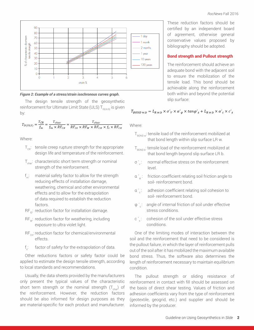
The design strength of the reinforcement should be based on the strength available at the end of the design life (TCR), once geosynthetic reinforcements are subject to creep strain. This strength may be determined from isochronous load/strain (creep) curves, for example as shown below:
Guideline on Using Geosynthetics in Slide
MSc. Cristina F. Schmidt Eng. Thiago Ordonho Araújo
Courtesy of
From the Engineering Department
Figure 1: Define support properties window of Slide software.
RocNews Fall 2016
Guideline on Using Geosynthetics in Slide 2
The design tensile strength of the geosynthetic reinforcement for Ultimate Limit State (ULS) TD(ULS) is given by:
Where:
TCR: tensile creep rupture strength for the appropriate design life and temperature of the reinforcement.
Tchar: characteristic short term strength or nominal strength of the reinforcement.
fm: material safety factor to allow for the strength reducing effects of installation damage,
weathering, chemical and other environmental effects and to allow for the extrapolation
of data required to establish the reduction factors.
RFID: reduction factor for installation damage.
RFW: reduction factor for weathering, including exposure to ultra violet light.
RFCH: reduction factor for chemical/environmental effects.
fs: factor of safety for the extrapolation of data.
Other reductions factors or safety factor could be applied to estimate the design tensile strength, according to local standards and recommendations.
Usually, the data sheets provided by the manufacturers only present the typical values of the characteristic short term strength or the nominal strength (Tchar) of the reinforcement. However, the reduction factors should be also informed for design purposes as they are material-specific for each product and manufacturer.
These reduction factors should be certified by an independent board of agreement, otherwise general conservative values proposed by bibliography should be adopted.
Bond strength and Pullout strength
The reinforcement should achieve an adequate bond with the adjacent soil to ensure the mobilization of the tensile load. This bond should be achievable along the reinforcement both within and beyond the potential slip surface:
Where:
TBOND w: tensile load of the reinforcement mobilized at that bond length within slip surface LR w.
TBOND b: tensile load of the reinforcement mobilized at that bond length beyond slip surface LR b.
σ ´v : normal effective stress on the reinforcement level.
α´φ: friction coefficient relating soil friction angle to soil- reinforcement bond.
α´c : adhesion coefficient relating soil cohesion to soil- reinforcement bond.
φ ´s : angle of internal friction of soil under effective stress conditions.
c ´s : cohesion of the soil under effective stress conditions.
One of the limiting modes of interaction between the soil and the reinforcement that need to be considered is the pullout failure, in which the layer of reinforcement pulls out of the soil after it has mobilized the maximum available bond stress. Thus, the software also determines the length of reinforcement necessary to maintain equilibrium condition.
The pullout strength or sliding resistance of reinforcement in contact with fill should be assessed on the basis of direct shear testing. Values of friction and adhesion coefficients vary from the type of reinforcement (geotextile, geogrid, etc.) and supplier and should be informed by the producer.
Figure 2: Example of a stress/strain isochronous curves graph.
RocNews Fall 2016
Guideline on Using Geosynthetics in Slide 3
Mobilized Strength
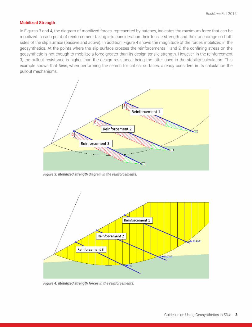
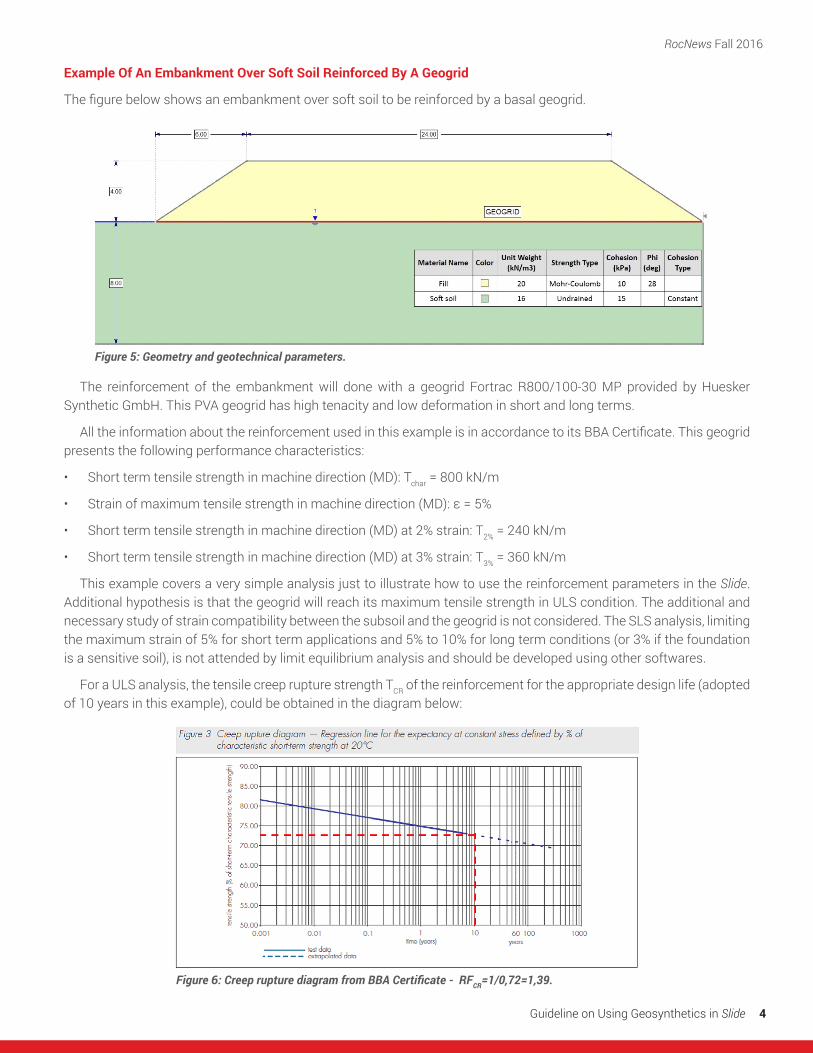
In Figures 3 and 4, the diagram of mobilized forces, represented by hatches, indicates the maximum force that can be mobilized in each point of reinforcement taking into consideration their tensile strength and their anchorage on both sides of the slip surface (passive and active). In addition, Figure 4 shows the magnitude of the forces mobilized in the geosynthetics. At the points where the slip surface crosses the reinforcements 1 and 2, the confining stress on the geosynthetic is not enough to mobilize a force greater than its design tensile strength. However, in the reinforcement 3, the pullout resistance is higher than the design resistance, being the latter used in the stability calculation. This example shows that Slide, when performing the search for critical surfaces, already considers in its calculation the pullout mechanisms.
Figure 3: Mobilized strength diagram in the reinforcements.
Figure 4: Mobilized strength forces in the reinforcements.
RocNews Fall 2016
Guideline on Using Geosynthetics in Slide 4
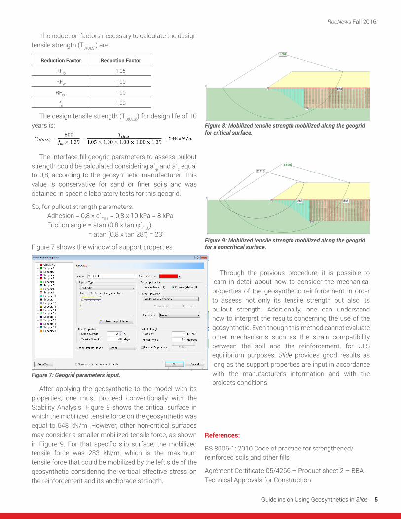
Example Of An Embankment Over Soft Soil Reinforced By A Geogrid
The figure below shows an embankment over soft soil to be reinforced by a basal geogrid.
The reinforcement of the embankment will done with a geogrid Fortrac R800/100-30 MP provided by Huesker Synthetic GmbH. This PVA geogrid has high tenacity and low deformation in short and long terms.
All the information about the reinforcement used in this example is in accordance to its BBA Certificate. This geogrid presents the following performance characteristics:
• Short term tensile strength in machine direction (MD): Tchar = 800 kN/m
• Strain of maximum tensile strength in machine direction (MD): ε = 5%
• Short term tensile strength in machine direction (MD) at 2% strain: T2% = 240 kN/m
• Short term tensile strength in machine direction (MD) at 3% strain: T3% = 360 kN/m
This example covers a very simple analysis just to illustrate how to use the reinforcement parameters in the Slide. Additional hypothesis is that the geogrid will reach its maximum tensile strength in ULS condition. The additional and necessary study of strain compatibility between the subsoil and the geogrid is not considered. The SLS analysis, limiting the maximum strain of 5% for short term applications and 5% to 10% for long term conditions (or 3% if the foundation is a sensitive soil), is not attended by limit equilibrium analysis and should be developed using other softwares.
For a ULS analysis, the tensile creep rupture strength TCR of the reinforcement for the appropriate design life (adopted of 10 years in this example), could be obtained in the diagram below:
Figure 6: Creep rupture diagram from BBA Certificate - 〖RFCR=1/0,72=1,39.
Figure 5: Geometry and geotechnical parameters.
RocNews Fall 2016
Guideline on Using Geosynthetics in Slide 5
The reduction factors necessary to calculate the design tensile strength (TD(ULS)) are:
Reduction Factor Reduction Factor
RFID 1,05
RFW 1,00
RFCH 1,00
fs 1,00
The design tensile strength (TD(ULS)) for design life of 10 years is:
The interface fill-geogrid parameters to assess pullout strength could be calculated considering a´φand a´c equal to 0,8, according to the geosynthetic manufacturer. This value is conservative for sand or finer soils and was obtained in specific laboratory tests for this geogrid.
So, for pullout strength parameters: Adhesion = 0,8 x c´FILL = 0,8 x 10 kPa = 8 kPaFriction angle = atan (0,8 x tan φ´FILL)
= atan (0,8 x tan 28°) = 23°
Figure 7 shows the window of support properties:
After applying the geosynthetic to the model with its properties, one must proceed conventionally with the Stability Analysis. Figure 8 shows the critical surface in which the mobilized tensile force on the geosynthetic was equal to 548 kN/m. However, other non-critical surfaces may consider a smaller mobilized tensile force, as shown in Figure 9. For that specific slip surface, the mobilized tensile force was 283 kN/m, which is the maximum tensile force that could be mobilized by the left side of the geosynthetic considering the vertical effective stress on the reinforcement and its anchorage strength.
Through the previous procedure, it is possible to learn in detail about how to consider the mechanical properties of the geosynthetic reinforcement in order to assess not only its tensile strength but also its pullout strength. Additionally, one can understand how to interpret the results concerning the use of the geosynthetic. Even though this method cannot evaluate other mechanisms such as the strain compatibility between the soil and the reinforcement, for ULS equilibrium purposes, Slide provides good results as long as the support properties are input in accordance with the manufacturer’s information and with the projects conditions.
References:
BS 8006-1: 2010 Code of practice for strengthened/reinforced soils and other fills
Agrément Certificate 05/4266 – Product sheet 2 – BBA Technical Approvals for Construction
Figure 8: Mobilized tensile strength mobilized along the geogrid for critical surface.
Figure 9: Mobilized tensile strength mobilized along the geogrid for a noncritical surface.
Figure 7: Geogrid parameters input.