guide valve limited...company profile guide valve limited, established in 1980 with its headquarters...
TRANSCRIPT

Guide Valve Limited
www.gvs-vci.com
GVS® Trunnion Mounted Metal to Metal & Triple Seated Ball Valves

COMPANY PROFILE
Guide Valve Limited, established in 1980 with its headquarters in Ontario, Canada, specializes in the manufacturing of valves. We are the manufacturer of the trademark brands such as, GVS®, VCI®, Lowe & GVS®-Malema. Our products are based on the most advanced technologies and are used in all sectors from petrochemical refining, process to transportation and distribution of the end product.GVS® valves are designed, manufactured & tested according to API 6D & CSA Z245.15 and available to API 608. Our standard product design of Series B1 & GB1 are of the trunnion mounted, bolted body forged type ball valves.
CANADA
USA
CHINA
UUSSAA2
AP 6D: 6D-1342ISO 9001:2015: 0052985-01
API 6D: 6D-1822API Spec Q1: Q1-3641ISO 9001:2015: ISO-3983

PRODUCT SERIES
Model B1ANSI Class 150
Model B1ANSI Class 300 to 1500
Model GB1ANSI Class 150 to 1500
3

B1-EXPLODED VIEW-ANSI CLASS 150 WAFER BODY
4
STEM SEAL (UPPER) SUB-ASSEMBLY DETAIL
SEAT SUB-ASSEMBLY DETAILDOUBLE PISTON EFFECT SEAT DESIGN
SEAT SUB-ASSEMBLY DETAILSINGLE PISTON EFFECT SEAT DESIGN
Gear operated option is available
STEM SEAL (LOWER) SUB-ASSEMBLY DETAIL
B1-EXPLODED VIEW-ANSI CLASS 150 WAFER BODY
4
STEM SEAL (UPPER) SUB-ASSEMBLY DETAIL
SEAT SUB-ASSEMBLY DETAILDOUBLE PISTON EFFECT SEAT DESIGN
SEAT SUB-ASSEMBLY DETAILSINGLE PISTON EFFECT SEAT DESIGN
Gear operated option is available
STEM SEAL (LOWER) SUB-ASSEMBLY DETAIL

B1-SECTION VIEW-ANSI CLASS 150 WAFER BODY
5
Position Part Description
6A Seat seal8 Seat springs9 Lower Trunnion10 Stem lower sleeve bearing11 Stem upper sleeve bearing12 Trunnion sleeve bearing13 Stem thrust washer15 Ball antistatic spring22 Body seal23A Body/end adapter capscrews25 Stem26 Stem key26A Stem key pin27 Stem antistatic spring27A Stem antistatic piston28 Stem flange29 Upper stem flange29A Lantern ring29B Disc spring29C Lower gland bushing33 Stem flange seal35 Stem upper seal35A Stem lower seal36A Washer42 Lower trunnion seal43 Split ring50 Lever 51 Lever knuckle (locking type)53 Lever knuckle - stem capscrew54 Lever knuckle - stem washer
3 Ball4 Seat 4A Seat Retainer4B Metal Ring
1 Body2 End adapter
ANSI 150
RF RTJ BWNPS B C D E F RFinch mm mm mm mm mm mm mm mm kg2 51 178 191 216 123 332 355 262 363 76.2 203 216 283 158 390 405 289 544 102 229 241 305 180 446 455 332 90
WEIGHT
A
VALVE SIZE BORE SIZE
A
ED
F
C
ØB
For gear operated option please contact factory.
60 Drain valve61A Solid plug72 Stem GBH grease fitting73 Stem inner check valve73A Stem inner grease O-ring73B Stem outer grease O-ring80 Lower trunnion capscrew81 Stem flange studs81A Stem flange nuts82 Upper stem flange capscrew83 Upper stem flange dowel pin
SIZE LENGTHNPS UNC inch
2 5/8-11 33 5/8-11 3 1/44 5/8-11 3 1/4
PIPELINE MOUNTING STUDVALVE SIZE

B1-EXPLODED VIEW-ANSI CLASS 300 TO 1500
Butt Weld Option
6
SEAT SUB-ASSEMBLY DETAILDOUBLE PISTON EFFECT SEAT DESIGN
SEAT SUB-ASSEMBLY DETAILSINGLE PISTON EFFECT SEAT DESIGN
Gear operated option is available
STEM SEAL (UPPER) SUB-ASSEMBLY DETAIL
STEM SEAL (LOWER) SUB-ASSEMBLY DETAIL
B1-EXPLODED VIEW-ANSI CLASS 300 TO 1500
Butt Weld Option
6
SEAT SUB-ASSEMBLY DETAILDOUBLE PISTON EFFECT SEAT DESIGN
SEAT SUB-ASSEMBLY DETAILSINGLE PISTON EFFECT SEAT DESIGN
Gear operated option is available
STEM SEAL (UPPER) SUB-ASSEMBLY DETAIL
STEM SEAL (LOWER) SUB-ASSEMBLY DETAIL

B1-SECTION VIEW-ANSI CLASS 300 TO 1500
Gear OperatedLever OperatedANSI 300
RF RTJ BWNPS B(xb) C D E* F RFinch mm mm mm mm mm mm mm mm kg2 51 216 232 216
3x2 76.2x51 283 298 2833 76.2 283 298 283
4x3 102x76.2 305 321 3054 102 305 321 305
6x4 152.4x10² 403 419 457ANSI 600
RF RTJ BWNPS B(xb) C D E* F RFinch mm mm mm mm mm mm mm mm kg2 51 292 295 292 123 332 580 262 43
3x2 76.2x51 356 359 356 123 332 580 262 483 76.2 356 359 356 158 390 710 289 64
4x3 102x76.2 432 435 432 158 390 710 289 86ANSI 900
RF RTJ BWNPS B(xb) C D E* F RFinch mm mm mm mm mm mm mm mm kg2 51 368 371 368 152 385 735 284 75
3x2 76.2x51 381 384 381 152 385 735 284 89
WEIGHT
A
VALVE SIZE BORE SIZE
WEIGHT
A
WEIGHT
A
VALVE SIZE BORE SIZE
VALVE SIZE BORE SIZE
4B Metal Ring6A Seat seal8 Seat springs9 Lower Trunnion10 Stem lower sleeve bearing11 Stem upper sleeve bearing12 Trunnion sleeve bearing13 Stem thrust washer15 Ball antistatic spring22 Body seal23 Body/end adapter studs24 Body/end adapter nuts25 Stem26 Stem key26A Stem key pin27 Stem antistatic spring27A Stem antistatic piston28 Stem flange29 Upper stem flange29A Lantern ring29B Disc spring29C Lower gland bushing33 Stem flange seal35 Stem upper seal35A Stem lower seal36A Washer42 Lower trunnion seal43 Split ring50 Lever 51 Lever knuckle (locking type)53 Lever knuckle - stem capscrew54 Lever knuckle - stem washer
ANSI 600
RF RTJ BWNPS B(xb) C D E F RFinch mm mm mm mm mm mm mm mm kg4 102 432 435 432 180 362 400 320 158
6x4 152.4x10² 559 562 559 180 362 400 320 226ANSI 900
RF RTJ BWNPS B(xb) C D E F RFinch mm mm mm mm mm mm mm mm kg3 76.2 381 384 381 193 368 400 326 135
4x3 102x76.2 457 460 457 193 368 400 326 1734 102 457 460 457 201 387 400 345 264
6x4 152.4x10² 610 613 610 201 387 400 345 308
VALVE SIZE BORE SIZE
VALVE SIZE BORE SIZE WEIGHT
WEIGHT
A
A
Position Part Description1 Body2 End adapter3 Ball4 Seat 4A Seat Retainer
A
E
D
F
C
Øb
ØB
ANSI 1500
RF RTJ BWNPS B(xb) C D E F RFinch mm mm mm mm mm mm mm mm kg
2 51 368 371 368 152 325 400 284 873x2 76.2x51 470 473 470 152 325 400 284 1013 76.2 470 473 470 205 380 400 338 142
4x3 102x76.2 546 549 546 205 380 400 338 1804 102 546 549 546 218 402 400 360 276
6x4 152.4x10² 705 711 705 218 402 400 360 320
A
VALVE SIZE WEIGHT
* Lever length. For gear operated option please contact factory.
BORE SIZE
7
123 332 430 262 39123 332 430 262 43158 390 550 289 58158 390 550 289 68180 446 610 320 111180 446 610 320 148
60 Drain valve61A Solid plug72 Stem GBH grease fitting73 Stem inner check valve73A Stem inner grease O-ring73B Stem outer grease O-ring80 Lower trunnion capscrew81 Stem flange studs81A Stem flange nuts82 Upper stem flange capscrew83 Upper stem flange dowel pin

GB1-EXPLODED VIEW-ANSI CLASS 150 TO 1500
Butt Weld Option
8

4B Metal Ring6A Seat seal8 Seat springs10 Stem lower sleeve bearing11 Stem upper sleeve bearing13 Stem thrust washer15 Ball antistatic spring16 Trunnion sleeve bearing17 Ball thrust washer18 Trunnion support pin19 Trunnion support22 Body seal23 Body/end adapter Studs 23B Body/end adapter studs(longer)24 Body/end adapter nuts25 Stem26 Stem key26B Stem key capscrew27 Stem antistatic spring27A Stem antistatic piston28 Stem flange29A Lantern ring29B Disc spring29C Lower gland bushing30 Top stop flange 33 Stem flange seal35 Stem upper seal35A Stem lower seal36A Washer43 Split ring55 Lifting lugs58 Valve support legs60 Drain valve61A Solid plug72 Stem GBH grease fitting73 Stem inner check valve73A Stem inner grease O-ring73B Stem outer grease O-ring
GB1-SECTION VIEW-ANSI CLASS 150 TO 1500
Position Part Description1 Body2 End adapter3 Ball4 Seat 4A Seat Retainer
SEAT SUB-ASSEMBLY DETAILDOUBLE PISTON EFFECT SEAT DESIGN
SEAT SUB-ASSEMBLY DETAILSINGLE PISTON EFFECT SEAT DESIGN
9
STEM SEAL (UPPER) SUB-ASSEMBLY DETAIL
STEM SEAL (LOWER) SUB-ASSEMBLY DETAIL
81 Stem flange studs76 Weather seal
81A Stem flange nuts82 Upper stem flange capscrew83 Upper stem flange dowel pin84 Stem flange/gearbox dowel pin85 Stem flange/gearbox studs86 Stem flange/gearbox nuts
99 Gearbox with handwheel(lockable)

GB1-DIMENSIONS-ANSI CLASS 150 TO 1500
10
Note: ANSI class 2500 is available upon request.
RF RTJ BWNPS B(xb) C D E F RFinch mm mm mm mm mm mm mm mm kg
6 152.4 394 406 457 325 437 400 395 2298x6 203.2x152.4 457 470 521 325 437 400 395 2668 203.2 457 470 521 360 480 400 438 365
10x8 254x203.2 533 546 559 360 480 400 438 42610 254 533 546 559 420 551 400 495 540
12x10 305x254 610 622 635 420 551 400 495 63012 305 610 622 635 457 623 600 572 828
14x10 337x305 686 699 762 420 551 400 495 81214 337 686 699 762 510 703 600 652 1086
16x12 387.4x337 762 775 838 457 623 600 572 104416 387.4 762 775 838 534 754 600 699 144218 438.2 864 876 914 560 793 700 729 2053
20x16 438.2x387.4 914 927 991 534 754 600 699 185720 489 914 927 991 580 805 700 743 2700
24x20 591x489 1067 1080 1143 580 805 700 743 346524 591 1067 1080 1143 715 935 700 850 4053
30x24 737x591 1295 / 1397 715 935 700 850 4825
VALVE SIZE BORE SIZE WEIGHTWEIGHT
ARF RTJ BW
NPS B(xb) C D E F RFinch mm mm mm mm mm mm mm mm kg
6 152.4 403 419 4578x6 203.2x152.4 502 518 5218 203.2 502 518 521
10x8 254x203.2 568 584 55910 254 568 584 559
12x10 305x254 648 664 63512 305 648 664 635
14x10 337x305 762 778 76214 337 762 778 762
16x12 387.4x337 838 854 83816 387.4 838 854 83818 438.2 914 930 914
20x16 438.2x387.4 991 1010 99120 489 991 1010 991
24x20 591x489 1143 1165 114324 591 1143 1165 1143
30x24 737x591 1397 1422 1397
VALVE SIZE WEIGHT
A
RF RTJ BWNPS B(xb) C D E F RFinch mm mm mm mm mm mm mm mm kg
6 152.4 559 562 5598x6 203.2x152.4 660 664 6608 203.2 660 664 660
10x8 254x203.2 787 791 78710 254 787 791 787
12x10 305x254 838 841 83812 305 838 841 838
14x10 337x305 889 892 88914 337 889 892 889
16x12 387.4x337 991 994 99116 387.4 991 994 99118 438.2 1092 1095 1092
20x16 438.2x387.4 1194 1200 119420 489 1194 1200 1194
24x20 591x489 1397 1407 139724 591 1397 1407 1397
30x24 737x591 1651 1664 1651
VALVE SIZE
A
WEIGHT RF RTJ BWNPS B(xb) C D E F RFinch mm mm mm mm mm mm mm mm kg
6 152.4 610 613 6108x6 203.2x152.4 737 740 7378 203.2 737 740 737
10x8 254x203.2 838 841 83810 254 838 841 838
12x10 305x254 965 968 96512 305 965 968 965
14x10 324x305 1029 1038 102914 324 1029 1038 1029
16x12 375x324 1130 1140 113016 375 1130 1140 113018 425.5 1219 1232 1219
20x16 425.5x375 1321 1334 132120 473.1 1321 1334 1321
24x20 571.5x473.1 1549 1568 154924 571.5 1549 1568 1549
30x24 714.4x571.5 1880 1902 /
VALVE SIZE
A
WEIGHT
ANSI 150 ANSI 300
ANSI 600 ANSI 900
A
D
ØB Øb
C
ØE
F
RF RTJ BWNPS B(xb) C D E F RFinch mm mm mm mm mm mm mm mm kg6 146.1 705 711 705 363 477 600 435 434
8x6 194x146.1 832 841 832 363 477 600 435 5068 194 832 841 832 418 538 600 492 678
10x8 241x194 991 1000 991 418 538 600 492 803
A
VALVE SIZE WEIGHT
ANSI 1500
325 437 400 395 252325 437 400 395 307360 480 400 438 429360 480 400 438 581420 551 400 495 601420 551 400 495 771457 623 600 572 908420 551 400 495 1020510 703 600 652 1291457 623 600 572 1145534 754 600 699 1791560 793 700 729 2370534 754 600 699 2140635 805 700 743 3000635 805 700 743 3849715 935 700 850 4503715 935 700 850 5361
325 437 400 395 390325 437 400 395 414360 480 400 438 559360 480 400 438 654420 551 600 495 850420 551 600 495 905457 623 600 572 1070420 551 600 495 1247510 703 600 652 1520457 623 600 572 1349534 754 700 699 2109560 793 700 729 2790534 754 700 699 2625650 868 700 783 3650650 868 700 783 4213730 935 700 850 5630730 935 700 850 6548
340 453 600 411 434340 453 600 411 506390 514 600 458 678390 514 600 458 803485 580 600 525 1206485 580 600 525 1414520 650 700 595 1594485 580 600 525 1518580 717 600 670 2060520 650 700 595 2009600 594 700 781 2420695 803 700 710 3346600 594 700 781 3081745 913 700 825 4238745 913 700 825 5336810 1012 700 910 6756810 1012 700 910 7858
BORE SIZE
BORE SIZE BORE SIZE
BORE SIZE

DESIGN FEATURES
FEATURES
- Bolted body type
- Full and reduced bore
- All forged steel components
- Firesafe certified anti-static devices
- Trunnion mounted, double block and bleed
- Anti-blow out stem design per API 608
- Double piston effect, self relieving seats, or combination
of the two seat designs
- Optional shut-off ratings
- Ball loads are distributed over large surface areas of two
self lubricating bearings, enabling them to work under a
low specific pressure thus reducing wear
- Very low bending loads are exerted on the trunnions
SEAT TO BODY SEALING OPTIONS:
- Graphite
- O-ring with back-up rings
- DPE spring energized lip-seal
- SPE spring energized lip-seal
- Chevron® V-ring packing
- Elastomeric O-ring
- DPE shuttle with elastomeric o-rings
- Elastomeric O-ring loaded U-seal
FLOW
FLOW
Double isolation – by – self relieving ball sealing design
Self-relieving ball sealing design
Double isolation design
Optional Valve Seat Sealing Designs
API 6D - DIB-2
11
UP TO +240°C (464°F) UP TO +350°C (662°F)
FLOW
API 6D - DIB-1
Note: Higher temperature design is available upon request.

COATING OPTIONS
SIXEAL® is recommended onto our GVS® Trunnion Mounted Metal to Metal Ball Valves where high resistance to abrasion, corrosion and wearing are required. For example, in slurry and sandy environments SIXEAL® is a viable alternative to HVOF coating.
SIXEAL® Technology:
Micro-particles of silicon carbide are added into the ENP bath to obtain a final plating in which incorporated sub-particles are evenly distributed all over the treated surfaces. The result is a homogeneous hard-faced element strongly incorporated in a nickel matrix, matching the hardness properties of silicon and the chemical resistance of ENP. This uniquely developed process is based on electroless nickel plating procedure. SIXEAL® coating thickness is maintained equally all over the coated surfaces, “complete ball”. This process eliminates any further grinding or machining of the ball’s outer surface.
12
Coatings ENP Tungsten Carbide
Chromium Carbide SIXEAL®
Typical Hardness (Hv) 1000 1050 850 1200
Recommended Operating Temperature (°C) -196 up to 240 -196 up to 230 -146 up to 550 -196 up to 550
Thickness (μm) 10 - 75 150 - 400 150 - 400 15 - 75
STD Roughness (Ra) 0.20 0.25 0.25 0.20
Superfinishing (Ra) 0.10 0.15 0.15 0.10
Perfect Fit Excellent Excellent Excellent Excellent
Hardness Excellent Excellent Fair Excellent
Coating Uniformity On All Surfaces Yes No No Yes
Constant Torque Performance Good Good Fair Good
Wearing, Abrasion and Erosion Resistance Good Good Fair Excellent
Note: Higher temperature coating is available upon request.

FUGITIVE EMISSION / FIRESAFE
FIRESAFE CERTIFICATIONGVS® ball valves are "FIRESAFE" certified
to meet international standards.
API 607API 6FABS 6755 Part 2
FUGITIVE EMISSION CERTIFICATION
13
ISO 15848-2:2006ANSI/ISA S93.00.01
UP TO + 350°C (662°F) DESIGN UP TO + 240°C (464°F) DESIGN
Note: Higher temperature design is available upon request.

TRIPLE SEATED TRUNNION MOUNTED BALL VALVES
Triple seat feature is offered by Guide Valve Limited to assure tight sealing in both low pressure and high pressure operation points. Triple sealing is suitable for many applications; in particular for critical condition to guarantee tight sealing in every pressure condition. This is achieved by means of combining Guide Valve's unique seat to ball design which is incorporating our patented special shaped Delta seat with the Protector / Scraper seat and metal seat design.Triple seat to ball sealing design allows to have three different type of seals: resin, elastomeric (Delta) and metal sealing.The special shaped Delta seat (US design patent#: US 731, 035S and Canadian design patent#: 155048) ensures zero leakage at very low pressure and continues to provide shut-off at higher pressures.
Resin seat insert provides seat to ball shut-off performance as well as protecting the special shaped Delta seat.Furthermore, the metal contact face of the seat to the ball provides ball to seat shut-off sealing and protects the resin and elastomeric seats from wearing and scraping.
Triple Seat Seal Feature
14

15
TRIPLE SEATED TRUNNION MOUNTED BALL VALVES
1 2 3
ANSI Valve ClassElastomeric (Delta) sealing
working from:Resin sealingworking from:
Metal sealingworking from:
150
300
600
900
1500
2500
0 psi 0 psi 0 psi
ANTI-EXPLOSIVE DECOMPRESSION SEALSAll of the elastic compounds present a permeability to gases at different levels. The pressured gas penetrates below the O-ring surface forming air pockets in the intermolecular spaces. The quantity of absorbed gas depends on the type of the compound, the gas in contact with it, the temperature andpressure of the gas.The instance described previous can be the cause of damage to the O-ring, if it is followed by an abrupt reduction in pressure and the consequent dilation of the ring, the gas included in the compound has an explosive behavior. The explosion of the air pockets contained in the compound causes the laceration of the O-ring surfaces. All GVS® Triple Seated Trunnion Mounted Ball valves have AED, “Anti-Explosive Decompression” O-ring. Therefore the above “Explosive Decompression” can not occur.
DECOMPRESSION HOLES
COATED BALL
COATED SEAT
SEAT SPRINGS
SPECIAL SHAPED DELTA SEAT
THERMOPLASTIC RESIN SEAT
16
TRIPLE SEATED TRUNNION MOUNTED BALL VALVES
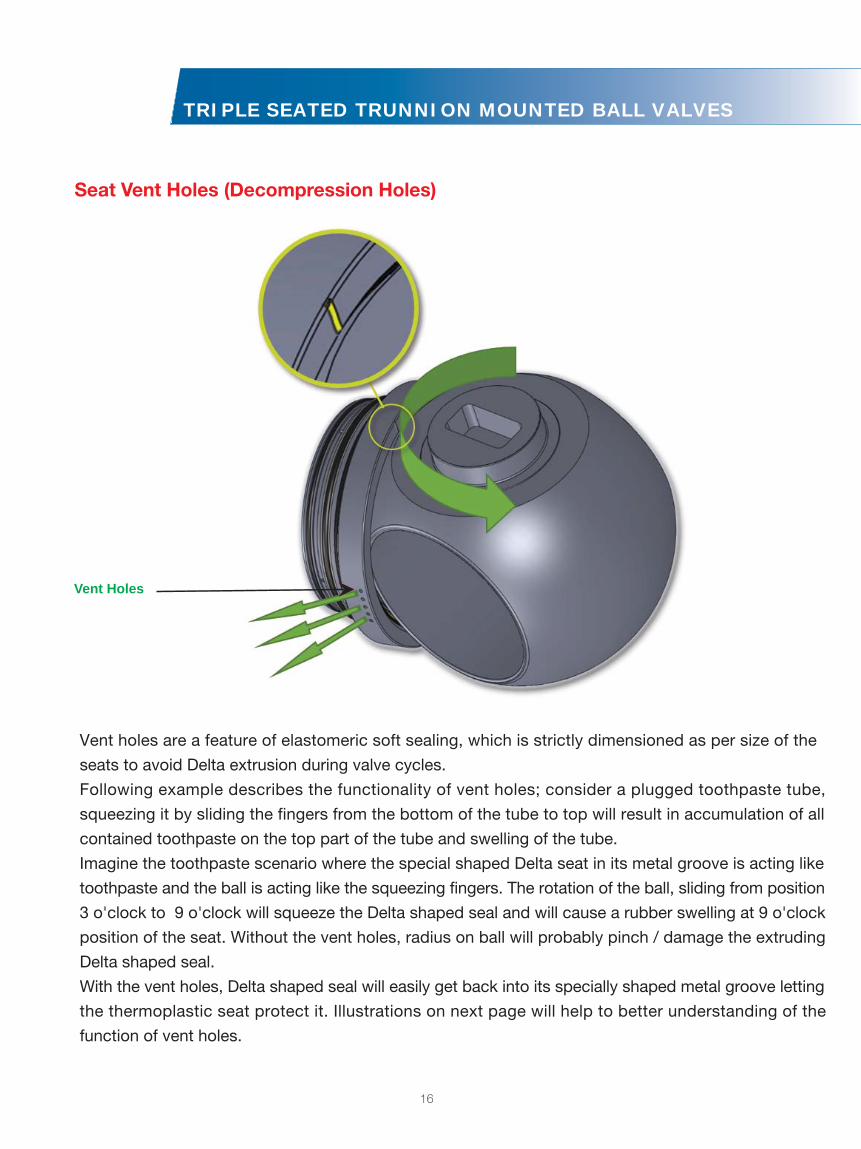
Vent holes are a feature of elastomeric soft sealing, which is strictly dimensioned as per size of the
seats to avoid Delta extrusion during valve cycles.
Following example describes the functionality of vent holes; consider a plugged toothpaste tube,
squeezing it by sliding the fingers from the bottom of the tube to top will result in accumulation of all
contained toothpaste on the top part of the tube and swelling of the tube.
Imagine the toothpaste scenario where the special shaped Delta seat in its metal groove is acting like
toothpaste and the ball is acting like the squeezing fingers. The rotation of the ball, sliding from position
3 o'clock to 9 o'clock will squeeze the Delta shaped seal and will cause a rubber swelling at 9 o'clock
position of the seat. Without the vent holes, radius on ball will probably pinch / damage the extruding
Delta shaped seal.
With the vent holes, Delta shaped seal will easily get back into its specially shaped metal groove letting
the thermoplastic seat protect it. Illustrations on next page will help to better understanding of the
function of vent holes.
Seat Vent Holes (Decompression Holes)
Vent Holes

17
TRIPLE SEATED TRUNNION MOUNTED BALL VALVES
How Vent Hole Works
Phase 3-Valve is being closed at 85°:Delta seat detaches from radial hole but in this condition the pressure difference does not permit any fluid injection into groove and the trapped pressure is relieved from the relief holes.
Phase 4-Valve is closed at 90°:Delta seat goes back into its initial condition and the elastomeric Delta shaped seat naturally and hermetically plugs the radial relief holes.
Phase 1-Valve is being closed at 45°:Delta seat is being compressed gradually by ball, creating a very thin pressure chamber.
Phase 2-Valve is being closed at 70°:Delta seat continues pushing any fluid in the groove from the top of the seat to the radial holes.
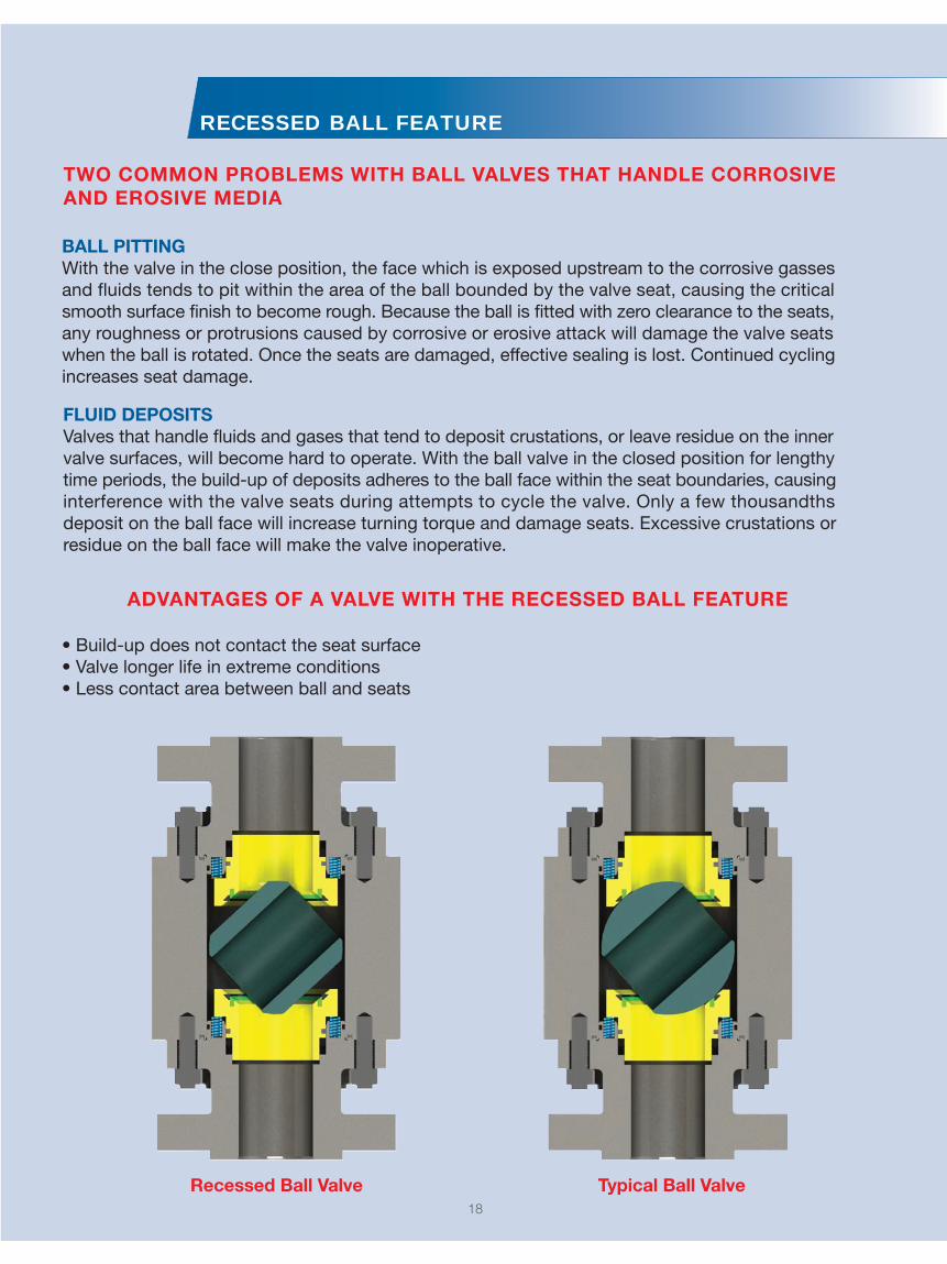
RECESSED BALL FEATURE
BALL PITTINGWith the valve in the close position, the face which is exposed upstream to the corrosive gasses and fluids tends to pit within the area of the ball bounded by the valve seat, causing the critical smooth surface finish to become rough. Because the ball is fitted with zero clearance to the seats, any roughness or protrusions caused by corrosive or erosive attack will damage the valve seats when the ball is rotated. Once the seats are damaged, effective sealing is lost. Continued cycling increases seat damage.
FLUID DEPOSITSValves that handle fluids and gases that tend to deposit crustations, or leave residue on the inner valve surfaces, will become hard to operate. With the ball valve in the closed position for lengthy time periods, the build-up of deposits adheres to the ball face within the seat boundaries, causing interference with the valve seats during attempts to cycle the valve. Only a few thousandths deposit on the ball face will increase turning torque and damage seats. Excessive crustations or residue on the ball face will make the valve inoperative.
Recessed Ball Valve Typical Ball Valve
TWO COMMON PROBLEMS WITH BALL VALVES THAT HANDLE CORROSIVE AND EROSIVE MEDIA
ADVANTAGES OF A VALVE WITH THE RECESSED BALL FEATURE
18


Fugitive Emission Test Report
ANSI/ISA S93.00.01
Performed for
Guide Valve Limited
www.gvs-vci.com
10 inch Class 300 Ball Valve
with Pneumatic Actuator
Product Code: GVS 10-GB1-300-RF
Project Number: 215087
Test Start Date: June 22, 2015
Performed by
YARMOUTH RESEARCH AND TECHNOLOGY, LLC
434 Walnut Hill Road
North Yarmouth, ME 04097 USA
(207) 829-5359
www.yarmouthresearch.com
Fire Test ReportANSI/API Standard 607, 6th Edition, 2010
ISO 10497: 2010API Standard 6FA, Third Edition, April 1999Performed forGuide Valve Limited www.gvs-vci.com
8 inch Class 600 Trunnion Mount Ball Valve
Product Code: 08-GB1-600-RF-G-20Project Number: 213033Test Date: January 31, 2014
Performed byYARMOUTH RESEARCH AND TECHNOLOGY, LLC
434 Walnut Hill RoadNorth Yarmouth, ME 04097 USA(207) [email protected]
Distributor / Agent:
Guide Valve Limited Guide Valve USA Limited
[email protected] Toll Free: 1-888-824-5693www.gvs-vci.com
51 Terecar Dr., Unit 1Woodbridge, ON CANADA L4L 0B5Tel: 905-761-7877Fax: 905-761-7917
7500 San Felipe St., Ste 600Houston, Texas USA 77063
CAT-GVSMTMTMBV-01-2019