guide to fuse selection - schurter · 2015 guide to fuse selection 16 application example: total...
TRANSCRIPT

Guide to Fuse Selection

Purpose of Fuses
> Circuit protection is critical, and in many cases
required, in electrical and electronic products.
> Fuses are an inexpensive and effective way to
protect your device from damage due to overcurrent
conditions.
> Fuses can prevent safety hazards to the end user
such as fire and catastrophic failure of the product.
> Fuses help design engineers comply with regulatory
agencies such as UL and IEC.
2015 Guide to Fuse Selection 2

Characteristics of Fuses
SCHURTER offers a wide variety of fuses to meet any application:
> Package type (SMD, through-hole & cartridge)
> Current and voltage ratings (AC and DC power)
> Trip characteristics (Quick-acting or time-lag)
> Breaking capacity ratings
> Approvals (UL, CSA, ENEC and CCC)
2015 Guide to Fuse Selection 3

Sizing and Mounting
> SCHURTER offers 0402, 0603 and 1206 SMD
fuses
> Through-hole microfuses
> Cartridge fuses 5x20mm, 6.3x32mm and
10.3x38mm
> Cartridge fuses can be mounted in fuseholders,
fuseblocks or fuseclips
> We also offer pigtails for a low cost through-hole
solution
2015 Guide to Fuse Selection 4

Fuse Current Rating
> The rated current of the fuse is either designed according to IEC
characteristic or UL characteristic.
> A fuse, which is designed according to a IEC standard, can continuously
operate at 100% of rated current of the fuse.
> A fuse, which is designed according to a UL standard, can continuously
operate at 75% of rated current of the fuse.
> The fuse current rating should be based on the operating current in the
application.
2015 Guide to Fuse Selection 5

Breaking Capacity
> Breaking capacity is the maximum short circuit current a fuse can
safely blow without a catastrophic failure such as a fire, breakage
or explosion.
> Low and high breaking capacity ratings typically range from 35A
up to 20kA.
> The short circuit condition in the final product determines what
fuse breaking capacity is needed.
> Our UMT is a compact SMD fuse with a high breaking capacity of
200A.
2015 Guide to Fuse Selection 6

Trip Characteristic
> Fuses are either quick-acting or time-lag
> Time-lag fuses trip at a slower rate at high currents.
2015 Guide to Fuse Selection 7
Quick-acting Time-lag
Load type Resistive Capacitive
Inrush Current
Withstand
Low High (10 times
rated current)
Applications •Data/signal lines
•Electronic
components
•Power supplies
•Motors
•Circuits with
capacitors
Advantage •Avoid damage
downstream due to
inrush
•Avoid nuisance
tripping during
inrush
Temperature Derating
> Fuse current ratings are measured at 23°C
> Fuses are temperature dependant so higher the ambient
temperature the quicker the fuse will blow
> Ambient temperature of the application must be considered when
choosing the current rating of the fuse
2015 Guide to Fuse Selection 8

Temperature Derating: Example UMT 250 SMD Fuse
> Calculation of rated current of
the fuse with the derating
curve:
2015 Guide to Fuse Selection 9
Application example:
Fuse type: UMT 250
Operating current: 1.0 A @ 60 C
Operating voltage: 230 VAC
Ambient temperature:< 60 C
A 22.10.82
1.0A
ctorDeratingFa
II
Operating
N
Choice: UMT 250, 1.25 A
(1 A @ 60 C)
Derating-curve UMT 250 (see data sheet)

Heat Issues
> Heat dissipated from fuses can affect other components in close
proximity and vice versa.
> Sufficient airflow and ventilation should be considered when
designing fuses in the application.
> SCHURTER fuseholder and fused module datasheets have
power acceptance ratings which show how much heat dissipation
it can withstand safely.
> If a fuse dissipates more heat than the fuseholder can withstand,
the fuseholder can degrade such as melt or burn.
2015 Guide to Fuse Selection 10Fused module Fuse and fuseholder

Power (Heat) Dissipation
> Fuses dissipate heat during normal operation and this can
increase as ambient temperature increases.
> Time-lag fuses generally have lower power dissipation values
than quick-acting fuses because they have a thicker fuse wire
diameter.
> Here’s our FST spec sheet where we publish the typical Power
Dissipation value.
> When choosing a fuseholder or fused module, the power
acceptance value should exceed the fuse power dissipation
value.
2015 Guide to Fuse Selection 11
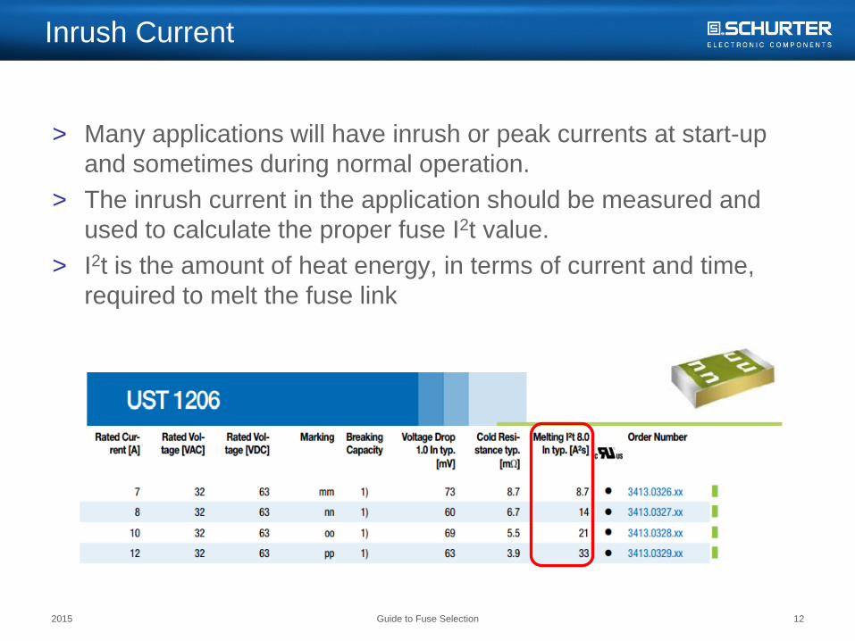
Inrush Current
> Many applications will have inrush or peak currents at start-up
and sometimes during normal operation.
> The inrush current in the application should be measured and
used to calculate the proper fuse I2t value.
> I2t is the amount of heat energy, in terms of current and time,
required to melt the fuse link
2015 Guide to Fuse Selection 12

Waveforms: Inrush Current Peak
Procedure
> Step 1: Selection of the appropriate waveform of the inrush
current
2015 Guide to Fuse Selection 13
Most used curveWave shapes Formulas Wave shapes Formulas

I2t Calculation: Inrush Current Peak
> Step 2: Calculation of the I2t-value of the application
2015 Guide to Fuse Selection 14
sA 0.507s 0.006 *A) (132
1 τ*I
2
1tI 222
pnApplicatio
2
After 5, the inrush
current has reached
operating current.
Application example:
Inrush current peak: Ip = 13 A, = 0.006 s
Type of waveform: Typical discharge curve
> Calculation of the I2t-value

Pulse Factor Derating: Inrush Current Peak
> Continuous exposure to pulses of high current could prematurely
age the fuse.
> The number of pulses the fuse would be exposed to in the
application should also be considered when choosing a fuse.
2015 Guide to Fuse Selection 15
Tin plating of
new fuse wire
Tin plating of
aged fuse wire
Wire
Tin plating

Pulse Factor Derating: Inrush Current Peak
> Step 3: Determine the minimum value of the I2t-value of the fuse.
> Calculation of time-lag T fuses
> (Calculation of quick-acting F fuses)
2015 Guide to Fuse Selection 16
Application example:
Total number of pulses in life cycle: 10,000
UMT 250 = time-lag fuses
sA 1.0350.49
s0.507A
F
tItI 2
2nApplicatio
2
Fuse_F_min
2
sA 1.7480.29
s0.507A
F
tItI 2
2nApplicatio
2
Fuse_T_min
2
Pulse-Derating curve
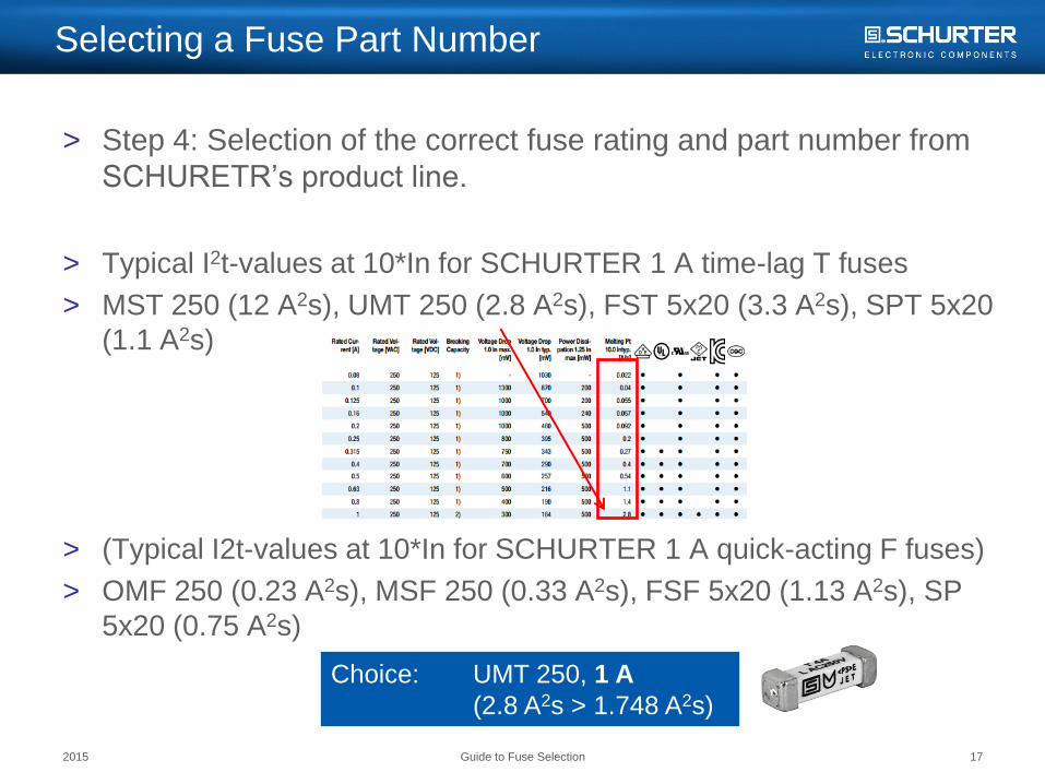
Selecting a Fuse Part Number
> Step 4: Selection of the correct fuse rating and part number from
SCHURETR’s product line.
> Typical I2t-values at 10*In for SCHURTER 1 A time-lag T fuses
> MST 250 (12 A2s), UMT 250 (2.8 A2s), FST 5x20 (3.3 A2s), SPT 5x20
(1.1 A2s)
> (Typical I2t-values at 10*In for SCHURTER 1 A quick-acting F fuses)
> OMF 250 (0.23 A2s), MSF 250 (0.33 A2s), FSF 5x20 (1.13 A2s), SP
5x20 (0.75 A2s)
2015 Guide to Fuse Selection 17
Choice: UMT 250, 1 A
(2.8 A2s > 1.748 A2s)
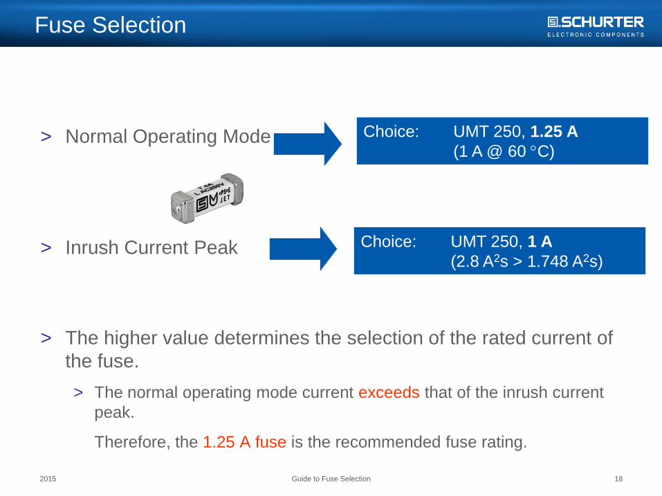
Fuse Selection
> Normal Operating Mode
> Inrush Current Peak
> The higher value determines the selection of the rated current of
the fuse.
> The normal operating mode current exceeds that of the inrush current
peak.
Therefore, the 1.25 A fuse is the recommended fuse rating.
2015 Guide to Fuse Selection 18
Choice: UMT 250, 1.25 A
(1 A @ 60 C)
Choice: UMT 250, 1 A
(2.8 A2s > 1.748 A2s)

Additional Information
2015 Guide to Fuse Selection 19
Additional Information
> Website enables quick access to:
> Selection Charts
> Datasheets
> Approval Documentation
> CAD Drawings
> White Paper & Application
Notes
Technical Assistance
> For general product questions,
contact Cora Umlauf at:
> For technical assistance or specific
design configurations, contact
Nikila Kareesan at:
(707) 636-3000
(800) 848-2600