guidance on the process for selecting alternatives to hcfcs in foams
TRANSCRIPT
Guidance on the Process for selectinG alternatives to hcfcs in foams
Sourcebook on technology options for safeguarding the ozone layer and the global climate system
ph
as
e-o
ut o
f h
cfs in
th
e f
le
xib
le a
nd r
igid
fo
am
se
ct
or

2
Guidance on the Process for Selecting Alternatives to HCFCs in Foams Sourcebook on technology options for Safeguarding the Ozone Layer and the Global Climate System
Prepared by:
Caleb Management Services Ltd
The Old Dairy, Woodend Farm
Cromhall, Wotton-Under-Edge
Gloucestershire, GL12 8AA
United Kingdom
July 2010
Copyright © United Nations Environment Programme, 2010
This publication may be reproduced in whole or in part and in any form for educational or non-profit purposes without special permission from the copyright holder, provided acknowledgement of the source is made. UNEP would appreciate receiving a copy of any publication that uses this publication as a source.
No use of this publication may be made for resale or for any other commercial purpose whatsoever without prior permission in writing from the United Nations Environment Programme.
Disclaimer
The designations employed and the presentation of the material in this publication do not imply the expression of any opinion whatsoever on the part of the United Nations Environment Programme concerning the legal status of any country, territory, city or area or of its authorities, or concerning delimitation of its frontiers or boundaries. Moreover, the views expressed do not necessarily represent the decision or the stated policy of the United Nations Environment Programme, nor does citing of trade names or commercial processes constitute endorsement.
UNEP Job number: DTI/1281/PA

UNEP DTIE Foam Sourcebook - 2010
3
I ACKNOWLEDGEMENTSThis publication was produced by the UNEP Division of Technology, Industry and Economics (DTIE) OzonAction Branch as part of UNEP’s work programme as an Implementing Agency of the Multilateral Fund for the Implementation of the Montreal Protocol.
The project was managed by the following team in the OzonAction Branch, UNEP DTIE, France:
Mr. Rajendra Shende, Head
Mr. James S. Curlin, Interim Network and Policy Manager
Mr. Ruperto De Jesus, Programme Assistant
This publication was written by:
Mr. Paul Ashford, Managing Director, Caleb Management Services Limited
Prof. Miguel Quintero, Consultant
with support from
Dr. Jason Yapp, Senior Consultant, Caleb Management Services Limited
Ms Hookyung Kim, Project Officer, Caleb Management Services Limited
The quality reviewers were:
Dr. Mike Jeffs, Consultant
Mr. Bert Veenendaal, Principal, RAPPA Inc.
Mr. Bob Russell, President, RJR Consulting
Other reviewers were:
Dr. Ezra Clark, Programme Officer, OzonAction Branch, UNEP DTIE, France
Mr. Etienne Gonin Project Coordinating Consultant, EC JumpStart Project, OzonAction Branch, UNEP DTIE, France
Dr. Janusz Kozakiewicz, Associate Professor, Head of Ozone Layer and Climate Protection Unit, ICRI, Poland
Design:
Mr. Andrew Laver, Creative Director, UK Design
II GLOSSARYABS – Acrylonitrile-butadiene-styrene
CAR – Climate Action Reserve
CDM – Clean Development Mechanism
CEIT – Countries with Economies in Transition
CFC – Chlorofluorcarbons
CHP – Combined Heat and Power
COC – Polyether(C-O-C stretch)
COOC – Polyester(C-O-O-C stretch)
DME – Dimethyl Ether
Executive Committee – Executive Committee of the Multilateral Fund of the Montreal Protocol
FTOC – The UNEP Foams Technical Options Committee
FUA – The functional unit approach
GEF – The Global Environment Fund
GWP – Global Warming Potential
HC – Hydrocarbons
HCFCs – Hydrochlorofluorocarbons
HFC – Hydrofluorocarbons
HFO – Hydrofluoroolefin – an alternative name for unsaturated HFCs
HIPS – High Impact Polystyrene
HPMP – HCFC Phase-out Management Plan
IOC – Incremental Operating Costs
IPCC/TEAP – Intergovernmental Panel on Climate Change, the Technology and Economic Assessment Panel
ISF – Integral skin foam
ISO – International Standards Organisation
ITH – the Integrated Time Horizon
LCA – Lifecycle Assessment
LCCP – Lifecycle Climate Performance
LVC – Low volume ODS consuming country
MCII – The Climate Indicator under development at the MLF secretariat
MDI – Methylene Di-phenyl Di-isocyanate
MF – Methyl Formate
MLF –United Nations Multilateral Fund for the Implementation of the Montreal Protocol
NCO – Polymers containing isocyanate groups
ODP – Ozone Depletion Potential
ODS – Ozone Depleting Substances
OEL – An occupational exposure level
OH – Hydroxyl
World Bank/OORG – The World Bank’s Ozone Operations Resource Group
ORNL – the US Department of Energy’s Oak
Ridge National Laboratory
PFC – Perfluorocarbon
PIR – Polyisocyanurate
PU OCF – Polyurethane One Component Foam
PUR – Rigid Polyurethane
RAC – Refrigeration and Air Conditioning
s-HFCs – Saturated HFCs
SME – Small Medium Enterprises
SNAP – Significant New Alternatives Program
SROC – Special Report on Ozone and Climate (IPCC/TEAP, 2005)
TDI – Toluene diisocyanate
TEWI – Total Equivalent Warming Impact
TLV – Threshold Limit Value
u-HFCs – Unsaturated HFCs
VCM – The Voluntary Carbon Market
VCS – The Voluntary Carbon Standard
VOC – Volatile Organic Compounds
XPS – Extruded polystyrene foams

4
III Why this sourcebook is important
At the Meeting of the Parties that fittingly took place in Montreal in October 2007 to celebrate the establishment of the Montreal Protocol on Substances that Deplete the Ozone Layer 20 years earlier, the Parties entered into an agreement which has taken the Protocol community into a new phase of activity.
Noting that the projected on-going use of hydrochlorofluorocarbons (HCFCs) was likely to place additional and avoidable ozone and climate burdens on the atmosphere, the Parties, in Decision XIX/6 (see full text in Annex 10-3), created a framework within which the phase-out of use of HCFCs could be accelerated over and above the 2016 freeze and final phase-out in 2040 originally foreseen within the Beijing Amendment. The new steps introduced as a result of the Decision imposed an earlier freeze, together with a step-wise country-level reduction in the intervening years leading to a phase-out of HCFC use in most applications by 2030.
For many, the step was clearly necessary in view of the rapid growth in consumption of HCFCs in developing (Article 5) countries as existing HCFC uses continued to grow in importance (e.g. commercial refrigeration) and chlorofluorocarbon (CFC) phase-out requirements necessitated the selection of interim HCFC-based technologies, often on economic grounds.
In practice, the Decision has created a number of precedents, perhaps the most important of which is the fact that Decision XIX/6 is the first under the Montreal Protocol to explicitly address climate concerns in its framework. Although it does not mandate technology choices that are optimal from a climate perspective, the Decision identifies and allocates the responsibilities for consideration of the climate component of technology selection. In doing so, it also requires the development of appropriate methods for assessing climate impacts, not only at product level but also at enterprise level, since the Montreal Protocol continues to provide its technology transition support to the enterprise itself or to the government agencies managing national transitions.
With the ozone obligations from Decision XIX/6 mandated, and the climate components (as well as other environmental effects) requiring assessment and prioritisation, there is now a more complex set of criteria to be managed than has ever been the case before. It is not always the case that what is the best for ozone is best for climate and therefore value judgements need to be made, not only at enterprise level, but also at national compliance level. The introduction of HCFC Phase-out Management Plans (HPMPs) by the Executive Committee of the Multilateral Fund for the implementation of the Montreal Protocol (Executive Committee) aims at ensuring that the overall objectives of Decision XIX/6 are
achieved. However, to be fully effective, these need to straddle the whole phase-out period from 2010 to 2030. This is not possible, at the enterprise level and much of the high-level planning needs to be completed at sectoral level, at the very least. A list of possible legislative and policy options that may facilitate HCFC phase out is included in the booklet published recently by UNEP that can be found at http://www.unep.fr/ozonaction/topics/hcfc.asp
The two main sectors using substantial quantities of HCFCs currently are the refrigeration and air conditioning (RAC) sector on the one hand and the foam sector on the other (see pie chart). The current HCFC usage patterns themselves are only part of the story, since these will change with time depending on the availability of alternative technologies. In addition, factors such as the emission profiles through the lifecycle of the products and equipment using HCFCs affect overall climate impact and all vary considerably between sectors. As a consequence, all of these factors need to be considered in parallel in order to build up the full climate picture (see Section 3). In practice, however, both consumption and emissions from the RAC sector are likely to dominate the consumption and emissions patterns for the foreseeable future.
Even though the RAC sector will remain the primary focus for major climate benefits, the foam sector is still a critical part of

UNEP DTIE Foam Sourcebook - 2010
5!
Estimated Consumption of HCFCs in Developing Countries in 2010(~445,000 tonnes)
Other 2%
Refrigeration and AC 77%
Foams 21%
most HPMPs, since these are driven by consumption criteria only. Accordingly, this Sourcebook provides guidance to the foam sector itself, and those operating both in it and with it, regarding the factors to be considered when choosing alternative technologies within the framework of Decision XIX/6. The guidance also gives consideration to methods of quantifying and potentially financing climate benefits, although notes that not all alternative technologies are, by definition, favourable to climate.
This Sourcebook builds on earlier technology and policy materials, developed by UNEP OzonAction to assist the foam industry in Article 5 countries to phase out CFCs, and seeks to continue and further develop that same capacity-building and information sharing service.
Source: IPCC/UNEP data

6
Contents
UNEP DTIE Foam Sourcebook - 2010
7
I ACKNOWLEDGEMENTS 3
II Glossary 3
III WHY THIS SOURCEBOOK IS IMPORTANT 4
1 INTRODUCTION 8
1.1 THE CHALLENGE OF ACCELERATED HCFC PHASE-OUT 9
1.2 GUIDANCE ON THE USE OF THIS SOURCEBOOK 10
2 THE INTERFACE BETWEEN OZONE DEPLETION & CLIMATE CHANGE 12
2.1 MEASURING IMPACTS – ODP, GWP AND CARBON INTENSITY 13
2.2 DECISION XIX/6 AND THE FRAMEWORK FOR MITIGATION 15
2.3 POTENTIAL BENEFITS FOR BUSINESS AND THE ENVIRONMENT 16
3 METHODS OF QUANTIFYING CLIMATE IMPACT 18
3.1 LIFECYCLE APPROACHES BASED ON DIRECT EMISSIONS ONLY 19
3.2 LIFE CYCLE APPROACHES ALSO CONSIDERING ENERGY 20
3.3 HYBRID APPROACHES (e.g. Functional Unit & Climate Indicators) 21
4 FOAM MANUFACTURE AND EXISTING FLUOROCARBON TECHNOLOGIES 24
4.1 AN INTRODUCTION TO FOAM TYPES25 25
4.2 FOAM MANUFACTURE AND THE ROLE OF BLOWING AGENTS 29
4.3 POINTS IN THE SUPPLY CHAIN WHERE CONSUMPTION OCCURS (fully formulated polyol issue) 31
4.4 REASONS FOR ORIGINAL SELECTION OF CFCs & HCFCs 32
4.5 REASONS WHY HFCs ARE POTENTIAL REPLACEMENTS FOR HCFCs 34
4.6 WHY HFCs CAN BE SUB-OPTIMAL SOLUTIONS FOR CLIMATE 35
5 GENERAL REVIEW OF ALTERNATIVE BLOWING AGENTS 40
5.1 HYDROCARBONS (both directly added and pre-blended) 41
5.2 LIQUID CARBON DIOXIDE 42
5.3 IN-SITU CARBON DIOXIDE (water blown foams) 42
5.4 OXYGENATED HYDROCARBONS (Methyl Formate, Methylal and Dimethyl Ether) 42
5.5 CHLORINATED HYDROCARBONS (Methylene Chloride, Trans-1,2 di-chloroethylene and 2-chloropropane) 44
5.6 SATURATED HFCs 45
5.7 UNSATURATED HFCS (HFOS) 46
6 DECISION-MAKING PROCESS 48
6.1 ESTABLISHING TECHNICAL FEASIBILITY & ECONOMIC VIABILITY 49
6.2 EVALUATING SAFETY ASPECTS & ENVIRONMENTAL IMPACT 50
6.3 ASSESSING COST EFFECTIVENESS AND PRACTICALITY 51
6.4 SUMMARY DECISION TREE 51
7 REVIEW OF SPECIFIC FACTORS INFLUENCING THE SELECTION OF ALTERNATIVE TECHNOLOGIES AT APPLICATION LEVEL 54
7.1 PU RIGID 55
7.1.1 PU RIGID – Domestic Refrigerators & Freezers 61
7.1.2 PU RIGID – Other Appliances 63
7.1.3 PU RIGID – Transport and Reefers 65
7.1.4 PU RIGID - Boardstock 67
7.1.5 PU RIGID – Continuous Panels 68
7.1.6 PU RIGID – Discontinuous Panels 69
7.1.7 PU RIGID – Spray 70
7.1.8 PU RIGID – Blocks 72
7.1.9 PU RIGID – Pipe-in-Pipe 73
7.1.10 PU RIGID – One Component Foam 74
7.2 PU FLEXIBLE FOAMS 75
7.2.1 PU FLEXIBLE – Integral Skin (Automotive) 79
7.2.2 PU FLEXIBLE – Integral Skin (Automotive) 80
7.3 PHENOLIC 80
7.3.1 PHENOLIC – Boardstock 83
7.3.2 PHENOLIC – Blocks 84
7.4 THERMOPLASTIC FOAMS 85
7.4.1 EXTRUDED POLYSTYRENE – Board 89
7.4.2 POLYOLEFIN FOAMS 90
8 FUNDING STRATEGIES 92
8.1 FUNDING THE OZONE COMPONENT 93
8.2 CLIMATE CO-FUNDING OPPORTUNITIES WITHIN THE MONTREAL PROTOCOL FRAMEWORK 95
9 CONCLUSIONS 96
10 ANNEXES 100
10.1 SOURCES OF INFORMATION15 101
10.2 CONTACT DETAILS OF BLOWING AGENT & OTHER PROVIDERS 103
10.3 FULL TEXT OF DECISION XIX/6 106
8
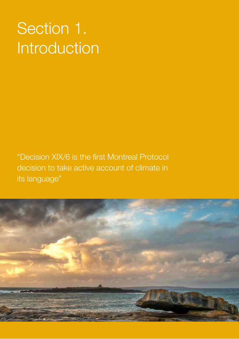
Section 1. Introduction
“Decision XIX/6 is the first Montreal Protocol decision to take active account of climate in its language”

9
UNEP DTIE Foam Sourcebook - 2010
1.1 The Challenge of Accelerated HCFC Phase-outThe Beijing Amendment of the Montreal Protocol, negotiated in 1999, set out the commitment of countries operating under Article 5 of the Protocol (developing countries) to freeze their consumption of HCFCs at 2015 levels ahead of final phase-out in 2040. This commitment was made alongside a more accelerated commitment of non-Article 5 countries (developed countries) to substantially phase down their use of HCFCs by 2015 and finally phase-out the small remaining ‘tail’ of use by 2030.
It was envisaged that, by the time technology transitions out of HCFCs in Article 5 countries were required, the non-HCFC technology in developed countries would already be well established. However, what was not fully foreseen was the fact that the backdrop for transition in Article 5 countries would be significantly different than for non-Article 5 countries in at least two respects:
I. The preponderance of small, medium enterprises (SMEs) in Article 5 countries would make it impossible to take advantage of the economies of scale available in non-Article 5 countries
II. By the time technology transition was being contemplated in Article 5 countries, the impact on climate of a number of HCFC alternatives would be fully understood and would need to be taken into consideration
Indeed, the concern over the climate impact of HCFCs themselves was to become another critical factor in the policy debate. Rapid growth in HCFC use, particularly in the consumption of HCFC-22, became increasingly evident through the early years of the 21st century, leading to predictions that much of the inadvertent climate benefit gained from the Montreal Protocol could be lost through increased emissions of HCFCs. It was in this spirit that Parties met at the 19th Meeting of the Parties to the Montreal Protocol in Montreal in 2007 to address this issue.
Decision XIX/6 was the result of that deliberation and was the first Montreal Protocol decision to take active account of climate in its language, while avoiding any binding commitments which might be considered as global climate legislation based around consumption rather than emission control. The Parties concluded that, in addition to efforts to reduce consumption by promoting good servicing practices in the refrigeration sector, the most effective way of avoiding the
climate impact of rapid growth in HCFCs was to accelerate their phase-out by advancing the freeze in production/consumption to 2013, based on the consumption in years 2009 and 2010, while introducing phase-down steps in the subsequent years of 2015, 2020, 2025 and 2030. The ‘old’ and the ‘new’ regimes are shown in the graphic below.
However, what became self-evident during the finalisation of the decision was that these additional climate benefits would be contingent on the use of HCFC substitutes that displayed lower climate impacts. This had not been considered as a significant factor when the bulk of HCFC phase-out had taken place in non-Article 5 countries and had led to technology transitions which were often no better in their climate profiles than the HCFCs they replaced. Recognising this reality, Parties were keen not to repeat this pattern in Article 5 countries but equally believed that they would have some influence on the outcome through the funding mechanisms available under the Montreal Protocol (primarily the Multilateral Fund).
In order to highlight this opportunity, the Parties included within the Decision language that required the Executive Committee of the Multilateral Fund to ‘give priority’ to cost-effective projects and technologies that
0%
20%
40%
60%
80%
100%
120%
140%
2008 2012 2016 2020 2024 2028 2032 2036 2040
NewBase
OldBase
Year
New A5 HCFC Measures
Old A5 HCFC Measures
Annual Growth Rate: 5%
Percentage of 2009-10 Baseline
Montreal Protocol HCFC phase-out schedule for Article 5 countries
Section 1. Introduction
Source: UNEP/Caleb
10
minimise other impacts on the environment, including on the climate, taking into account global warming potential, energy use and other relevant factors’. One of the key aspects of this language is that it includes not only the global warming potential of the substitute itself but also the lifecycle implications resulting from energy use. This will be explored further in Section 3.
As a consequence, the Parties had set a very challenging timeline for HCFC phase-out, with all the legal compliance issues that this entails, while making the selection of alternatives more demanding than it had hitherto been in non-Article 5 countries. As stakeholders began to assess this, there was a growing realisation that the priorities, both in terms of sectoral phase-out and technology choice might not be aligned to achieve both ozone compliance and maximum climate benefit simultaneously.
In an effort to approach the subject holistically, the Executive Committee of the Multilateral Fund introduced the concept of an HCFC Phase-out Management Plan (HPMP) which would be established for each Article 5 Party seeking to comply with Decision XIX/6. This would focus primarily on the early steps to accommodate the 2013 freeze and the 2015 reduction of 10% of HCFC consumption. However, it would also need to consider the overarching plan to meet the later phase-out objectives, while minimising climate impact. To plan at this level over such a long period is proving to be a major challenge and this Sourcebook is an attempt to assist foam sector stakeholders in assessing the relevant aspects.
In addition, further analysis of HCFC consumption in Article 5 countries revealed that the bulk of consumption was limited to just a few countries which had significant manufacturing capacity for refrigeration
equipment and/or foams. For other countries, HCFC consumption might be limited to servicing activities in the refrigeration sector. The challenges of meeting specific phase-down targets would be very different in these countries and might lead to different priorities, projects and programmes. This is an issue that is largely beyond the scope of this Sourcebook, since phase-out in the foam sector will take place at the manufacturing enterprises themselves or, where fully formulated polyols are used, in combination with their suppliers.. Nevertheless, care is needed to see the foam sector strategy as part of a larger HPMP and to realise that the pace of that strategy may be heavily influenced by the on-going HCFC needs in other areas.
A further factor may be the ‘worst first’ component of the Decision which states that:
11. To agree that the Executive Committee, when developing and applying the funding criteria for projects and programmes, and taking into account paragraph 6, gives priority to cost-effective projects and programmes which focus on, inter alia:
(a) phasing-out first those HCFCs with higher ozone depleting potential, taking into account national circumstances
….and may predicate against HCFC-141b (see Section 7).
1.2 Guidance on the use of this SourcebookThis Sourcebook is primarily intended to provide overarching guidance to National Ozone Units, Implementing Agencies and Project Proponents on the processes and techniques used to select alternative technologies. It does this by outlining the key factors to be considered and the principles that need to be applied to assess their significance. In Section 7 of the document, the state of technology development in each foam sector and the alternatives currently available are outlined. However, this is not done to provide definitive recommendations, but to offer real-life examples of the decision processes in action. These decision-processes are themselves outlined in Section 6.
The authors would stress that it would be impossible to provide definitive guidance on technology selection in a Sourcebook of this type, since it would very rapidly become outdated. Readers are therefore encouraged to use this Sourcebook alongside other sources of information such as the regular reports of the UNEP Foams Technical Options Committee (FTOC), publications by the Implementing Agencies (e.g. those from the Ozone Operations Resource Group of the World Bank), National Ozone Units, the outputs from Regional Workshops and Industry Conferences/Publications.

11
UNEP DTIE Foam Sourcebook - 2010
12
Section 2. The interface between ozone depletion and climate change
“Knowledge of the key environmental benefits of technology selection has been shown to provide a significant competitive advantage in the foam sector”
13
UNEP DTIE Foam Sourcebook - 2010
2.1 Measuring Impacts - ODP, GWP and Carbon Intensity of Energy UseThe scientific inter-relationship between ozone depletion and climate change is complex - partly because it occurs at a number of levels simultaneously and partly because there are feedback loops whereby changes on one side lead to changes on the other. These inter-linkages are extensively explained in the IPCC/TEAP Special Report on Ozone and Climate (SROC, 2005) and it is not the purpose of this Sourcebook to repeat those arguments here. Responsible technology selection, while phasing out HCFC use, can create a substantial overall climate benefit even when the offset of increased ozone levels (a greenhouse gas in its own right) is taken into account. The Montreal Protocol community has underpinned this principle by making clear that compliance with HCFC phase-out targets will not be compromised for reasons of climate protection as Decision XIX/6 is implemented.
In order to help policy-makers and other stakeholders to assess the competing claims of the alternatives in this complex scientific environment, a series of metrics have been introduced to provide guidance on the comparative impacts of options on both the ozone layer and on climate. These include, ozone depletion potential (ODP), global warming potential (GWP) and carbon intensity of energy, each of which will be considered in turn.
Ozone Depletion Potential (ODP) This measure of assessing the damage that a given substance could do to the stratospheric ozone layer was first introduced by the UNEP Scientific Assessment Panel in the years running up to the instigation of the Montreal Protocol in 1987. In simple terms, the impact of all substances is compared to a baseline centred on CFC-11 and CFC-12, which are both considered to have an ODP of 1. This process is usually called normalisation and is a common technique for this type of comparative analysis. Therefore HCFC-141b, the HCFC most commonly used as a foam
blowing agent, has an ODP of 0.11 because a molecule of HCFC-141b is likely to do only 11% of the damage in its stratospheric lifetime that would have been done by a molecule of CFC-11. It can be noted that all ozone depleting substances controlled by the Montreal Protocol have either chlorine or bromine atoms, or sometimes both, in their molecules. This is often combined with fluorine. Therefore, if a molecule contains fluorine but not bromine or chlorine atoms, it can be recognised as not controlled by the Montreal Protocol.
In practice, substances with lower ODPs often have shorter atmospheric lifetimes than those they replace. However, assessing precise atmospheric lifetimes can be complex and it may be necessary occasionally to revise ODPs based on new scientific evidence. This can create particular issues for policy-makers who normally require certainty to implement policies which need to be consistent over a number of years. Hence, there is sometimes an ‘official’ value (as stated in the Annexes of the Montreal Protocol) and a latest scientific value, which might be marginally different. Enterprises are encouraged to always use the official value in their assessments.
In some instances, the atmospheric lifetime of a substance can be so short that, even though it might contain chlorine or bromine, it is unlikely to reach the stratosphere at all. These substances therefore have no ozone depleting potential in practice. However, this does not mean that there are no circumstances under which a stray molecule might get to the stratosphere. Care should therefore be taken in using terms such as “zero-ODP”, even though they are widely used in marketing literature and, unfortunately, as a requirement in a number of product and building codes. Better terminology would be negligible ODP, but this seems to be rejected in practice because it is less emphatic.
Stakeholders should also note that there are a number of short life-time substances that are not controlled under the Montreal Protocol
even though they have measurable ODPs. The reason for this is that they are not considered sufficiently significant by policy-makers to have any bearing on the environmental outcome. Enterprises could well be best served, therefore, by using terms such as ‘controlled under the Montreal Protocol’ or ‘not controlled under the Montreal Protocol’, when referring to their blowing agents. It should be further noted that compliance with the Montreal Protocol is measured in terms of avoidance of controlled substances, not avoidance of ozone depleting substances (ODS).
Section 2. The interface between ozone depletion and climate chnange
14
Global Warming Potential (GWP) The metric described as Global Warming Potential (GWP) has a lot of similarities with ODP in that it is a comparative assessment of climate impact which is normalised against carbon dioxide (CO2 = 1). Many other parallels exist with ODP. For example, it is quite common for substances to have an official GWP (often based on the Assessment Reports of the Inter-Governmental Panel on Climate Change) and a latest scientific GWP. Therefore care needs to be taken in deciding which one to use.
Since the climate impact of a substance is also dependent on its lifetime, decisions have to be made about the period over which the comparison is made. Carbon oxide itself is a relatively long-lived molecule (50-200 years, depending on the circumstances) and therefore a comparison over 100 years has become accepted as something of a standard for policy-making purposes. The selected period is known technically as the Integrated Time Horizon or ITH. The approach taken under the Kyoto Protocol in adopting a ‘basket of gases approach’ to target setting required clear GWPs for each of the gases involved and these were quoted in the Second Assessment Report on the basis of a 100 year ITH. This has also become the basis for most carbon trading activities globally. However, the debate goes on about whether different time horizons would be more appropriate.
The level of contribution to global warming that can be attributed to a substance is primarily based on the ‘space’ it occupies in the radiative spectrum. This is referred to technically as its degree of radiative forcing. It so happens that chlorine and fluorine containing compounds (CFCs, HCFCs and HFCs) occupy a particular part of the spectrum that is otherwise uncluttered. This means that their impact is considerably higher than would normally be expected and leads to a high GWP. This subject is covered more specifically in Sections 4 and 5.
The main impact of the GWP of a gas is experienced only when it is released. Therefore efforts to reduce releases will either delay or, at best, totally avoid the climate impact of that gas within the lifecycle of the product or equipment in which it is being used. For foams, the main points of potential release are during foam manufacture and at end-of-life. In general, there is little emission during the use phase – particularly from insulating foams, where retention of blowing agent is critical performance.
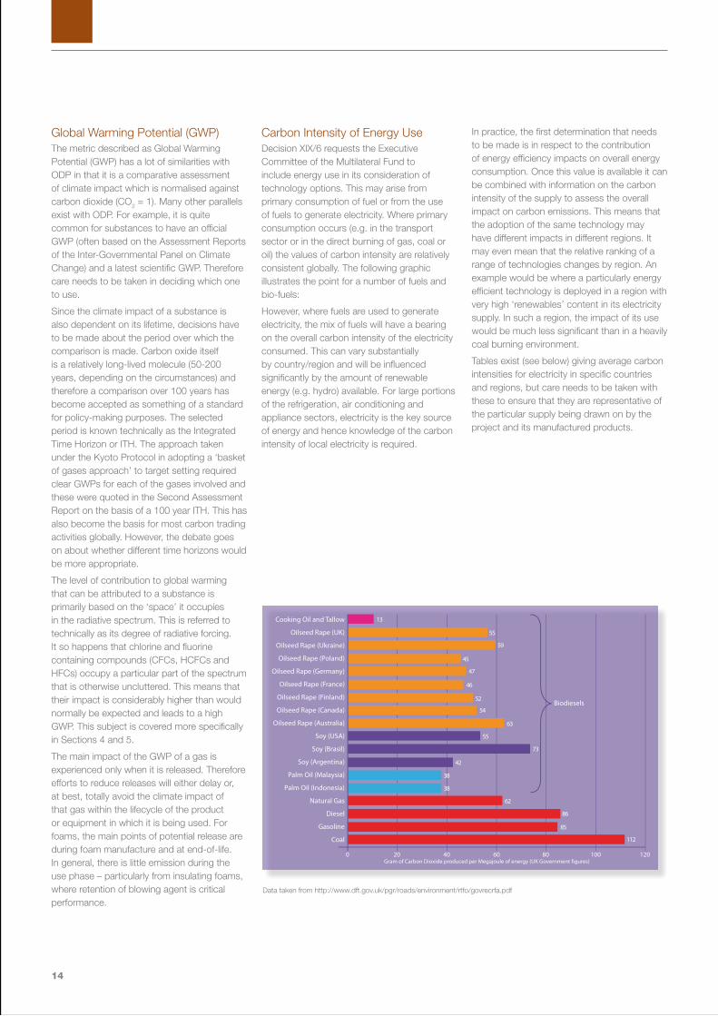
Carbon Intensity of Energy Use Decision XIX/6 requests the Executive Committee of the Multilateral Fund to include energy use in its consideration of technology options. This may arise from primary consumption of fuel or from the use of fuels to generate electricity. Where primary consumption occurs (e.g. in the transport sector or in the direct burning of gas, coal or oil) the values of carbon intensity are relatively consistent globally. The following graphic illustrates the point for a number of fuels and bio-fuels:
However, where fuels are used to generate electricity, the mix of fuels will have a bearing on the overall carbon intensity of the electricity consumed. This can vary substantially by country/region and will be influenced significantly by the amount of renewable energy (e.g. hydro) available. For large portions of the refrigeration, air conditioning and appliance sectors, electricity is the key source of energy and hence knowledge of the carbon intensity of local electricity is required.
In practice, the first determination that needs to be made is in respect to the contribution of energy efficiency impacts on overall energy consumption. Once this value is available it can be combined with information on the carbon intensity of the supply to assess the overall impact on carbon emissions. This means that the adoption of the same technology may have different impacts in different regions. It may even mean that the relative ranking of a range of technologies changes by region. An example would be where a particularly energy efficient technology is deployed in a region with very high ‘renewables’ content in its electricity supply. In such a region, the impact of its use would be much less significant than in a heavily coal burning environment.
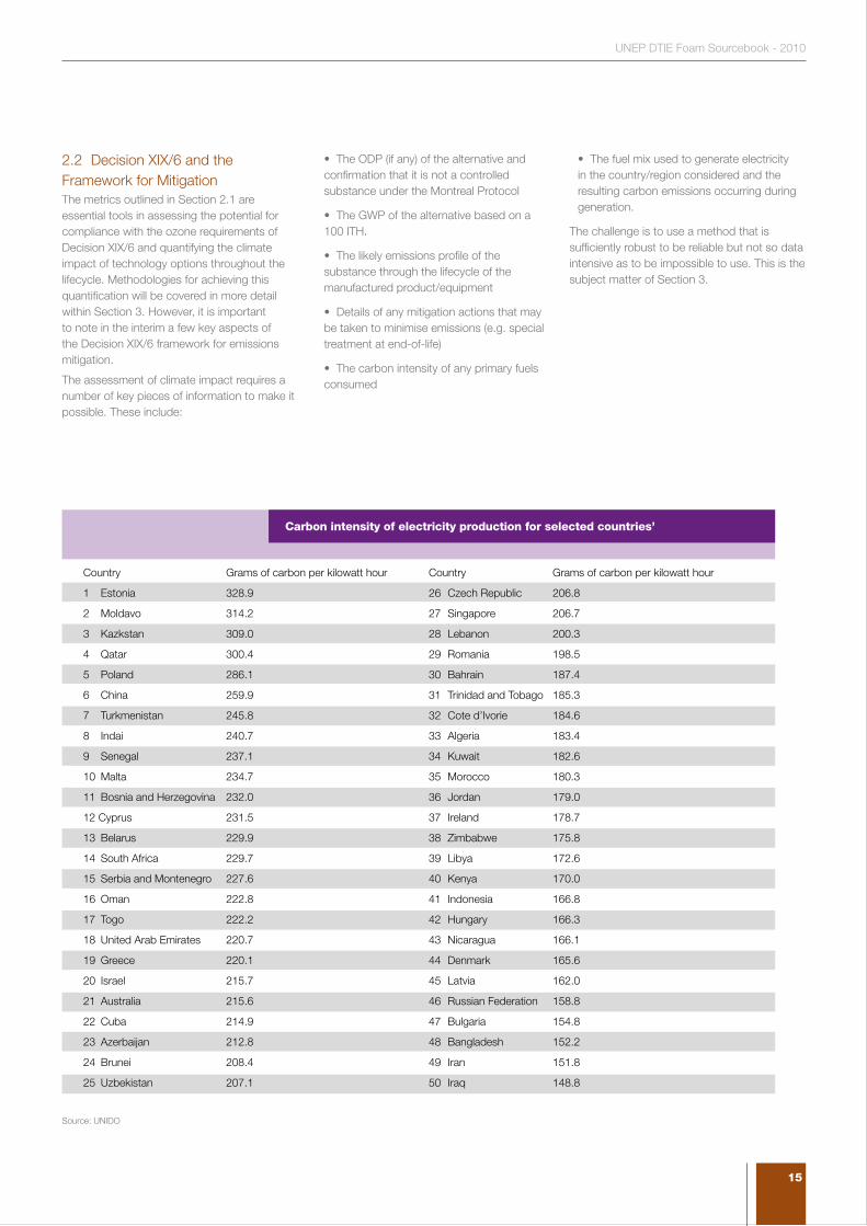
Tables exist (see below) giving average carbon intensities for electricity in specific countries and regions, but care needs to be taken with these to ensure that they are representative of the particular supply being drawn on by the project and its manufactured products.
0 20 40 60 80 100 120
!
Cooking Oil and Tallow
Oilseed Rape (UK)
Oilseed Rape (Ukraine)
Oilseed Rape (Poland)
Oilseed Rape (Germany)
Oilseed Rape (France)
Oilseed Rape (Finland)
Oilseed Rape (Canada)
Oilseed Rape (Australia)
Soy (USA)
Soy (Brasil)
Soy (Argentina)
Palm Oil (Malaysia)
Palm Oil (Indonesia)
Natural Gas
Diesel
Gasoline
Coal
Biodiesels
Gram of Carbon Dioxide produced per Megajoule of energy (UK Government �gures)
13
55
59
45
47
46
52
54
55
42
38
38
62
86
85
112
63
73
Data taken from http://www.dft.gov.uk/pgr/roads/environment/rtfo/govrecrfa.pdf
15
UNEP DTIE Foam Sourcebook - 2010
2.2 Decision XIX/6 and the Framework for Mitigation The metrics outlined in Section 2.1 are essential tools in assessing the potential for compliance with the ozone requirements of Decision XIX/6 and quantifying the climate impact of technology options throughout the lifecycle. Methodologies for achieving this quantification will be covered in more detail within Section 3. However, it is important to note in the interim a few key aspects of the Decision XIX/6 framework for emissions mitigation.
The assessment of climate impact requires a number of key pieces of information to make it possible. These include:
• The ODP (if any) of the alternative and confirmation that it is not a controlled substance under the Montreal Protocol
• The GWP of the alternative based on a 100 ITH.
• The likely emissions profile of the substance through the lifecycle of the manufactured product/equipment
• Details of any mitigation actions that may be taken to minimise emissions (e.g. special treatment at end-of-life)
• The carbon intensity of any primary fuels consumed
• The fuel mix used to generate electricity in the country/region considered and the resulting carbon emissions occurring during generation.
The challenge is to use a method that is sufficiently robust to be reliable but not so data intensive as to be impossible to use. This is the subject matter of Section 3.
Country Grams of carbon per kilowatt hour Country Grams of carbon per kilowatt hour
1 Estonia 328.9 26 Czech Republic 206.8
2 Moldavo 314.2 27 Singapore 206.7
3 Kazkstan 309.0 28 Lebanon 200.3
4 Qatar 300.4 29 Romania 198.5
5 Poland 286.1 30 Bahrain 187.4
6 China 259.9 31 Trinidad and Tobago 185.3
7 Turkmenistan 245.8 32 Cote d’Ivorie 184.6
8 Indai 240.7 33 Algeria 183.4
9 Senegal 237.1 34 Kuwait 182.6
10 Malta 234.7 35 Morocco 180.3
11 Bosnia and Herzegovina 232.0 36 Jordan 179.0
12 Cyprus 231.5 37 Ireland 178.7
13 Belarus 229.9 38 Zimbabwe 175.8
14 South Africa 229.7 39 Libya 172.6
15 Serbia and Montenegro 227.6 40 Kenya 170.0
16 Oman 222.8 41 Indonesia 166.8
17 Togo 222.2 42 Hungary 166.3
18 United Arab Emirates 220.7 43 Nicaragua 166.1
19 Greece 220.1 44 Denmark 165.6
20 Israel 215.7 45 Latvia 162.0
21 Australia 215.6 46 Russian Federation 158.8
22 Cuba 214.9 47 Bulgaria 154.8
23 Azerbaijan 212.8 48 Bangladesh 152.2
24 Brunei 208.4 49 Iran 151.8
25 Uzbekistan 207.1 50 Iraq 148.8
Carbon intensity of electricity production for selected countries’
Source: UNIDO
16
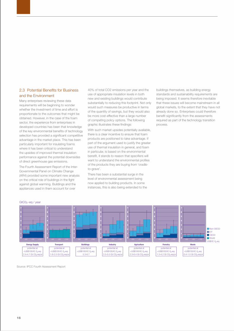
2.3 Potential Benefits for Business and the Environment Many enterprises reviewing these data requirements will be beginning to wonder whether the investment of time and effort is proportionate to the outcomes that might be obtained. However, in the case of the foam sector, the experience from enterprises in developed countries has been that knowledge of the key environmental benefits of technology selection has provided a significant competitive advantage in the market place. This has been particularly important for insulating foams where it has been critical to understand the upsides of improved thermal insulation performance against the potential downsides of direct greenhouse gas emissions.
The Fourth Assessment Report of the Inter-Governmental Panel on Climate Change (AR4) provided some important new analysis on the critical role of buildings in the fight against global warming. Buildings and the appliances used in them account for over
40% of total CO2 emissions per year and the use of appropriate insulation levels in both new and existing buildings would contribute substantially to reducing this footprint. Not only would such measures be productive in terms of the quantity of savings, but they would also be more cost-effective than a large number of competing policy options. The following graphic illustrates these findings:
With such market upsides potentially available, there is a clear incentive to ensure that foam products are positioned to take advantage. If part of the argument used to justify the greater use of thermal insulation in general, and foam in particular, is based on the environmental benefit, it stands to reason that specifiers will want to understand the environmental profiles of the products they are buying from ‘cradle-to-grave’.
There has been a substantial surge in the level of environmental assessment being now applied to building products. In some instances, this is also being extended to the
buildings themselves, as building energy standards and sustainability requirements are being imposed. It seems therefore inevitable that these issues will become mainstream in all global markets, to the extent that they have not already done so. Enterprises could therefore benefit significantly from the assessments required as part of the technology transition process.
0
1
2
3
4
5
6
7
<20 <50 <1000
1
2
3
4
5
6
7
<20 <50 <1000
1
2
3
4
5
6
7
<20 <50 <1000
1
2
3
4
5
6
7
<20 <50 <1000
1
2
3
4
5
6
7
<20 <50 <100
Energy Supply Transport Buildings Industry Agriculture
0
1
2
3
4
5
6
7
<20 <50 <1000
1
2
3
4
5
6
7
<20 <50 <100
Forestry Waste
GtC0 -eq / year2
potential at <US$100/tC 0 -eq: 2.4-4.7 Gt C0 -eq/yr
2
2
potential at <US$100/tC 0 -eq: 1.6-2.5 Gt C0 -eq/yr
2
2
potential at <US$100/tC 0 -eq: 2.5-5.5 Gt C0 -eq/yr
2
2
potential at <US$100/tC 0 -eq: 2.3-6.4 Gt C0 -eq/yr
2
2
potential at <US$100/tC 0 -eq: 1.3-4.2 Gt C0 -eq/yr
2
2
potential at <US$100/tC 0 -eq: 0.4-1.0 Gt C0 -eq/yr
2
2
potential at <US$100/tC 0 -eq:
5.3-6.72
US$/tC 0 -eq
Non-OECDEITOECDWorld
2
Source: IPCC Fourth Assessment Report

17
UNEP DTIE Foam Sourcebook - 2010
18
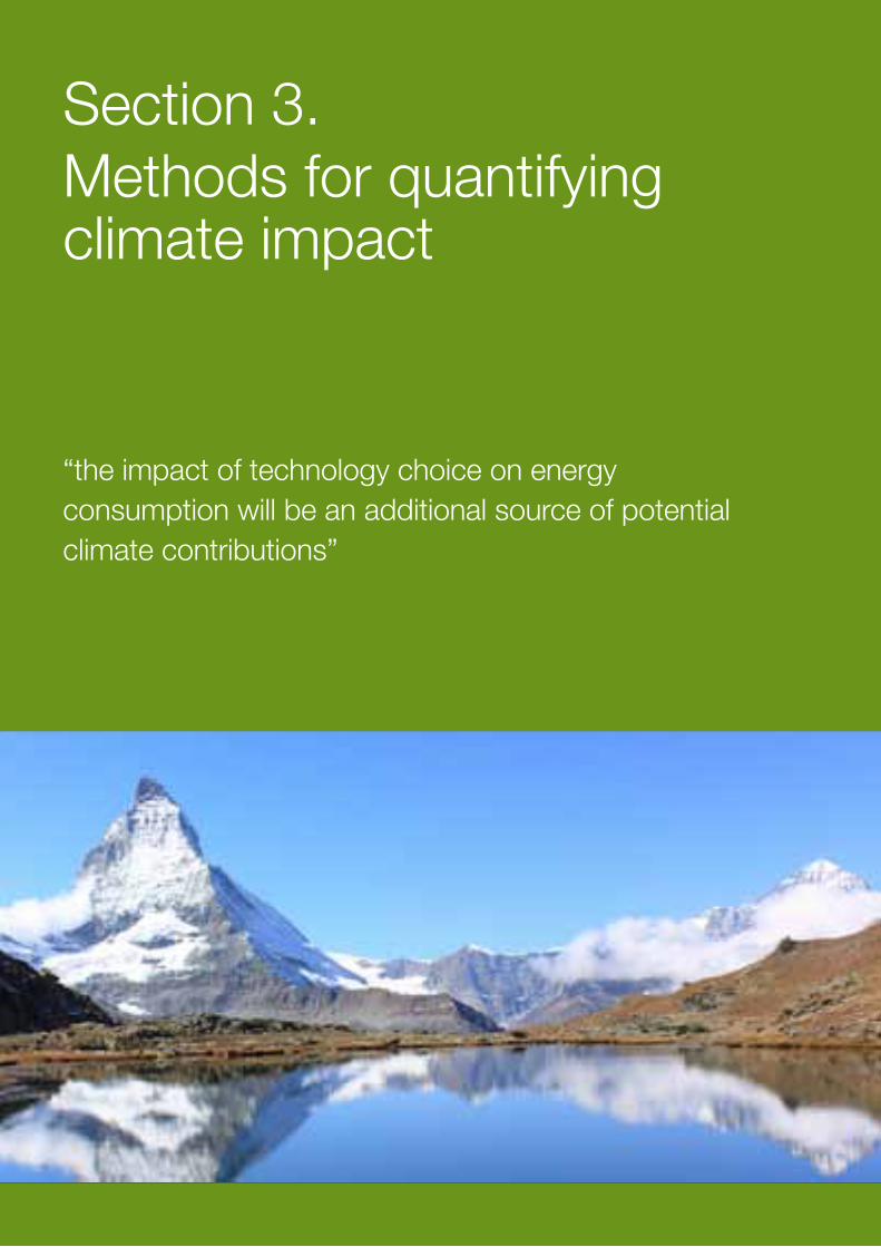
Section 3. Methods for quantifying climate impact
“the impact of technology choice on energy consumption will be an additional source of potential climate contributions”
19
UNEP DTIE Foam Sourcebook - 2010
Section 2.2 has already made reference to the fact that quantitative assessments of climate impact need to take account of activities that occur throughout the lifecycle of the products and/or equipment manufactured as a result of the implementation of a project.
However, when assessing technology transition projects at enterprise level, this can be a relatively complex and uncertain exercise, since the quantity and scope of products and/or equipment manufactured by an enterprise will not be known in full at the point of investment.
This challenge, however, is not insurmountable if the primary purpose for quantifying the climate impact of a measure is to compare technology options. In such cases, it is possible to take defined units of manufacture/production, based on typical demand patterns, and compare the relative climate impacts arising from specific technology choices prior to making a final decision. It is in this context, that this Sourcebook reviews the options available for quantifying climate impact.
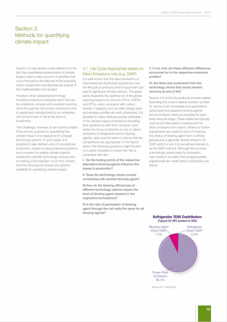
3.1 Life Cycle Approaches based on Direct Emissions only (e.g. GWP)It is well known that the direct emissions of chlorinated and fluorinated substances over the lifecycle of products and/or equipment can lead to significant climate impacts. The graph below illustrates the significance of the global warming impacts of common CFCs, HCFCs and HFCs, when compared with carbon dioxide. If aspects such as initial charge sizes and emission profiles are well understood, it is possible to make relatively precise estimates of the climate impact of emissions including their significance with time. However, even where the focus of attention is only on direct emissions of refrigerants and/or blowing agents, care must be taken to ensure that the comparisons are appropriate. In the foams sector, the following questions might be part of a useful checklist to ensure that ‘like is compared with like’:
I. Do the boiling points of the respective alternative blowing agents influence the losses in production?
II. Does the technology choice involve co-blowing with another blowing agent?
III. How do the blowing efficiencies of different technology options impact the level of blowing agent required in the respective formulations?
IV. Is the rate of permeation of blowing agent through the cell walls the same for all blowing agents?
V. If not, how are these diffusion differences accounted for in the respective emissions profiles?
VI. Are there any constraints from the technology choice that would prevent recovery at end of life?
Section 4.6 of this Sourcebook provides tables illustrating the current default emission profiles for various foam processes and applications using liquid and gaseous blowing agents. Annual emission rates are provided for each basic lifecycle stage. These tables are typically used as an initial basis of assessment for direct emissions from foams. Where no further adjustments are made for items II-VI above, the choice of blowing agent from a climate perspective is generally directly linked to its GWP, which is why it is sometimes referred to as the GWP method. Although this provides a temptingly simple basis for evaluation, care needs to be taken that all appropriately adjustments are made before conclusions are drawn.
!
Refrigerator TEWI Contributors(Typical for HFC product in USA)
RefrigerantDirect GWP
0.4%
Power PlantEmissions
92.4%
Blowing AgentDirect GWP
7.2%
Section 3. Methods for quantifying climate impact
Source A.D. Little (2002)
20
3.2 Life Cycle Approaches also considering energy (e.g. LCA, LCCP, TEWI) For both foam and refrigeration applications, it is well understood that the impact of technology choice on energy consumption will be an additional source of potential climate contributions. In many applications, the energy consumption component can be a dominant factor in the overall carbon footprint of the product or equipment. An example of this would be a domestic refrigerator where the following pie chart illustrates the relevant components of greenhouse gas emission over the lifecycle.
Although such graphs rightly draw attention to the fact that the focus of appliance designers should be on improving energy efficiency, they do not automatically lead to the conclusion that the choice of refrigerant or blowing agent is unimportant.
Where the choice of blowing agent can influence the energy efficiency of a refrigerator significantly, it may be that this effect will offset the direct emissions from eventual blowing agent release. However, the level to which this is the case will depend largely on the sensitivity of energy efficiency to such choices, which will in turn depend on the geometry of the appliance and the levels of insulation used. In practice, it is often the case that energy efficiency is only marginally influenced by these technology choices and, in such situations the comparative process reverts largely to a comparison of direct emissions only. This said, the inclusion of ‘energy use’ within the factors that must be considered under Decision XIX/6 requires that an appropriate lifecycle model is used. The following section outlines three options that have found application for this purpose.
All three methods featured below - Lifecycle Assessment (LCA), Total Equivalent Warming Impact (TEWI) and Lifecycle Climate Performance (LCCP) - focus on the performance of individual products or pieces of equipment. In this respect, they are amongst the most rigorous analyses available. However, as will be highlighted, they are data hungry and often limited in their application because of their focus on individual installations. They are of most use where the product/equipment is mass produced and where the performance
is largely independent of the local environment (e.g. domestic refrigerators). Accordingly, such techniques are typically used by product designers and also academics, seeking to make comparisons and plot trends. However, these techniques are of less value in assessing climate implications at enterprise or project
level.
Life Cycle Assessment (LCA) Life Cycle Assessment is effectively the ‘gold standard’ for such comparisons and not only includes climate related elements but many other environmental impacts. It has been the subject of a large degree of standardisation around the world and the current LCA principles are set out in detail within the International Standards Organisation (ISO) 14040 series of standards. As a result of its comprehensive nature, it is a very “data hungry” approach and requires substantial resources for satisfactory completion. Where the primary purpose of the activity is for technology comparison (as in this instance), Life Cycle Assessment would normally be considered as too cumbersome for the purpose. This has led practitioners to consider two other approaches which are focused solely on components relating to climate impact.
Total Equivalent Warming Impact (TEWI) Total Equivalent Warming Impact was first developed and introduced by the US Department of Energy’s Oak Ridge National Laboratory (ORNL) in the mid-1990s as a means of making relevant comparisons of climate impact for differing technology options. It was an effective initial tool, but came under later criticism because it did not fully consider the footprints associated with the earlier steps in the manufacturing process (for example, of the blowing agents themselves). In reality, this should never have been a criticism of the method, since every lifecycle comparative method has to define its boundaries. The failing was probably in not making them clear enough to those reviewing the outputs.
This experience highlights a further important point when developing and using lifecycle comparison tools - “always be sure to understand the boundary conditions of the model (i.e. what is included and what isn’t.)”
Life Cycle Climate Performance (LCCP) This method emerged in the wake of the TEWI experience and explicitly included the earlier climate footprints associated with the production of chemicals and other precursors. The term Life Cycle Climate Performance was used in earnest for the first time in the 1999 TEAP Task Force Report entitled “The Implications to the Montreal Protocol of the inclusion of HFCs and PFCs in the Kyoto Protocol”, in which the comparative impacts of a number of technology choices were assessed.
As with LCA, LCCP remains relatively “data hungry” despite its climate focus and is best applied to situations where there are a large number of replicated units (e.g. domestic refrigerators, mobile air conditioners etc.). Where applications are less well defined and are typically specified by their surroundings (e.g. building insulation or stationary air conditioning), there is a need for a less complex hybrid approach.

21
UNEP DTIE Foam Sourcebook - 2010
3.3 Hybrid Approaches (e.g. Functional Unit and Climate Indicators) Hybrid approaches of the type included in this section are targeted at addressing the more practical challenges of evaluating the climate impact of technology choices at enterprise or project level. This may also extend to the overall evaluation of HPMPs themselves. This higher level evaluation (which some have called ‘climate proofing’) is a critical part of the objectives of National Ozone Units, Implementing Agencies and other interested parties. In practice, hybrid approaches are expected to be more widely used in the implementation of Decision XIX/6 than the more formal methods of LCA, TEWI and LCCP. However, as pointed out in the sections that follow, care needs to be taken to maintain sufficient rigour to give reliable predictions of climate impact.
In addressing this concern for both practicality and rigour, and following the negotiation and finalisation of Decision XIX/6, there were substantial discussions about how the language concerning the evaluation of climate impact might be interpreted in practice. Some felt that a GWP-based approach would be sufficient, arguing that LCCP was too complex, particularly in applications where there were uncertainties about the use conditions. Others felt that LCCP was the only way in which the full text of the Decision could be implemented.
As a potential means of bridging this difference in view, two new approaches have emerged. These are the functional unit approach (FUA) and the Multilateral Fund Climate Indicator (MCII). Both methods have sought to provide guidance in technology selection specifically in the context of Decision XIX6.

Calculations HCFC-141b n-Pentane
Annual Foam Volume 7,143 m3 7,143 m3
Area of Insulation Created 128,571.17 m2 128,571.17 m2
Energy Transmitted in Lifetime 121722.17 MWh 189345.60 MWh
Carbon equivalent 23127.21 t-CO2-equiv 35975.66 t-CO2-equiv
Energy difference 67623.43 MWh
Carbon equivalent difference 12848.5 t-CO2-equiv
Blowing Agent Losses 25.00 tonnes 16.15 tonnes
Carbon equivalent 17825 t-CO2-equiv 178 t-CO2-equiv
Carbon equivalent difference -17647 t-CO2-equiv
Total Carbon Equivalents 17825 t-CO2-equiv 13026 t-CO2-equiv
Example of Foam Comparisons using the Functional Unit Approach for Foams (Constant Thickness)
22
Functional Unit Approach (FUA) This approach was originated in the foam sector and seeks to establish a basis for comparison of insulation foams in typical building or appliance applications. In doing so, it has needed to take account of matters such as building energy sources, local carbon intensity values for electricity generation and local building insulation standards. Since these vary between residential buildings and commercial/industrial buildings, it can be necessary to take into account the likely split of foam sales to each sector. However, by considering the fate of a typical unit of foam (the functional unit), the scenario for a particular manufacturing plant or enterprise can be established. As with other techniques, the fact that the tool is being used for comparative purposes means that the sensitivity to the assumptions used is somewhat diminished.
The table below provides an indication of the type of output obtained using the functional unit approach when comparisons are made between the old HCFC-141b technology and a replacement n-Pentane technology at constant thickness (constant thermal performance being the other typical basis of comparison). The calculations are based on the lifecycle impact of the annual production of an enterprise currently using 25 tonnes of HCFC-141b per year.
It can be seen that the better thermal performance of HCFC-141b results in less energy being transmitted through the foam during its lifetime and hence less CO2 emitted from power generation. However, the quantity of n-Pentane used in the foam is reduced because it has better blowing efficiency and its lower GWP also contributes to a net saving of around 4,800 tonnes CO2-equiv. when compared with the HCFC-141b baseline. If the comparison had been conducted on the basis of constant thermal performance, the n-Pentane option would have required additional thickness of foam and hence the embodied energy of the additional foam would have also needed to have been included in the comparison.
In a further enhancement of the Functional Unit Approach an attempt was made to assess likely differences in cost resulting from technology choices. This permitted the calculation of cost per unit of climate benefit for the first time. However, to do this, the model needed to assess the cost of a climate neutral transition (i.e. one with the same climate profile as the HCFC-141b technology being replaced). One of the interesting aspects to emerge from this assessment was that the climate mitigation costs (measured in US$ per tonne of CO2 saved) increased dramatically for technologies requiring significant capital investment as the size of the plant diminished. This observation was no more than a demonstration of the basic principles relating to economies of scale, first mentioned in Section 1 and elaborated further in Section 4.5 and elsewhere. Nevertheless, it did highlight the fact that climate mitigation costs in excess of US$200/tonne of CO2-equiv. might be incurred in the most extreme cases. Further detail on the basis for these analyses is found in the relevant MLF Executive Committee publication on the treatment of Environmental Issues in technology transition (Annex V of UNEP/OzL.Pro/ExCom/55/47).
Climate Indicators (e.g. MCII) Although foam scenarios could be relatively well modelled using the Functional Unit Approach, a further level of simplification was seen as necessary for the refrigeration sector. The UN Multilateral Fund Secretariat took direct responsibility for this further step and developed, in conjunction with experts in the field, a simplified model that essentially limited the refrigeration and air conditioning sector to five primary cooling scenarios. This further level of simplification has been seen to make the absolute comparative values less reliable but continues to provide sufficient certainty to allow for technology-ranking to take place.
As with the FUA, comparison with the technology being replaced is an important element of the assessment, since this has a strong bearing on whether it should be prioritised in an overall HCFC Phase-out Management Plan (HPMP) or not. In addition, the relative climate performance against such a benchmark can be used to incentivise or discourage certain technology selection options. Stakeholders are certainly advised to review periodically how quantified climate impacts might be used to assess technology appropriateness, funding eligibility and levels of support in future. This Sourcebook will return to this point in Section 8 where ‘Funding Strategies’ are considered.

23
UNEP DTIE Foam Sourcebook - 2010
24
Section 4.Foam manufacture and existing fluorocarbon technologies
“The characteristics of CFC-11 and CFC-12 were so appropriate for polymeric foams that they seemed ‘designed-for-purpose”

25
UNEP DTIE Foam Sourcebook - 2010
4.1 An introduction to Foam Types.
Polyurethane Foams (including Polyisocyanurate) Polyurethane Foam technologies were developed as early as the 1930s in flexible, rigid and semi-rigid forms, and have played a dominant role in the field of foamed polymers ever since. This is largely because of the technology’s basic capacity to produce materials with a wide range of critical end properties such as low density, consistent foam morphology, mechanical strength and resilience. In most cases, these properties can be achieved by relatively simple formulation adjustments, indicating the versatility of polyurethane chemistry.
Flexible foams, which demonstrate excellent elastic and deformation characteristics, find their major applications in the area of furniture cushioning (bedding, seating, carpet backing, etc.) and packaging (electronic, computer, china, equipments). Semi-rigid foams are used in the automotive industry (dash panel, liner, visors) and footwear (shoe soles) [Lee, 2006]. However, the largest single application for polyurethane rigid foam is in thermal insulation, although similar foams can also be used to provide structural integrity and buoyancy. For thermal insulation applications, old and modern buildings, transport systems and household appliances all take advantage of the excellent energy performance offered through the low thermal conductivity of the foam.
It is in the area of thermal insulation that the contribution of the blowing agent is at its most significant, since the gas in the foam cell is the major contributor to the overall thermal performance of the insulation. This subject is explored further in Section 4.2.
A variant of basic polyurethane chemistry is polyisocyanurate, which has greater rigidity and provides improved fire performance. However, it is less resilient and is therefore not a replacement for polyurethane in all applications.
Phenolic FoamsPhenolic foams take the characteristics of polyisocyanurate a step further and are very highly cross-linked. This makes them very rigid (high modulus) and, historically, has led to unacceptable friability where vibration or thermal shock is a factor. Nonetheless, more recent technologies have achieved very fine cell structures which have both improved the resilience of the foam and its thermal performance. Indeed, phenolic foam now typically delivers the best thermal performance among the insulating foam types available. However, this is not the primary reason for its use. Phenolic foam has made ground primarily because of its overall fire performance and, most importantly, low smoke generation.
As with polyurethane and polyisocyanurate, phenolic foams were historically blown with CFCs and have progressed through a number of alternatives which are documented in Sections 5 and 7.
Extruded Polystyrene
A number of polystyrene foam product types exist. Expanded polystyrene foams are blown from beads of polystyrene which already contain a hydrocarbon blowing agent (typically pentane). These beads are then expanded in hot moulds to create blocks and moulded shapes. For this reason, the foams have been used more for packaging than for demanding thermal insulation applications. These foams, sometimes referred to as bead foams, have never used CFCs as blowing agents and are not the subject of this [Sourcebook].
An alternative type of polystyrene foam is extruded polystyrene foam which, as its name suggests, is manufactured by an extrusion process at elevated temperatures. This product has historically used CFCs and their substitutes. The nature of the extrusion process is such that it creates more integral foams than those generated from beads and provides better thermal properties as a result. Some extruded products are manufactured specifically for construction applications and are typically referred to as ‘board’, while others are manufactured for packaging purposes, sometimes with a thermal component (e.g. disposable food packaging) and are typically known as ‘sheet’ products.
Section 4. Foam manufacture and existing flurocarbon tecnologies
26
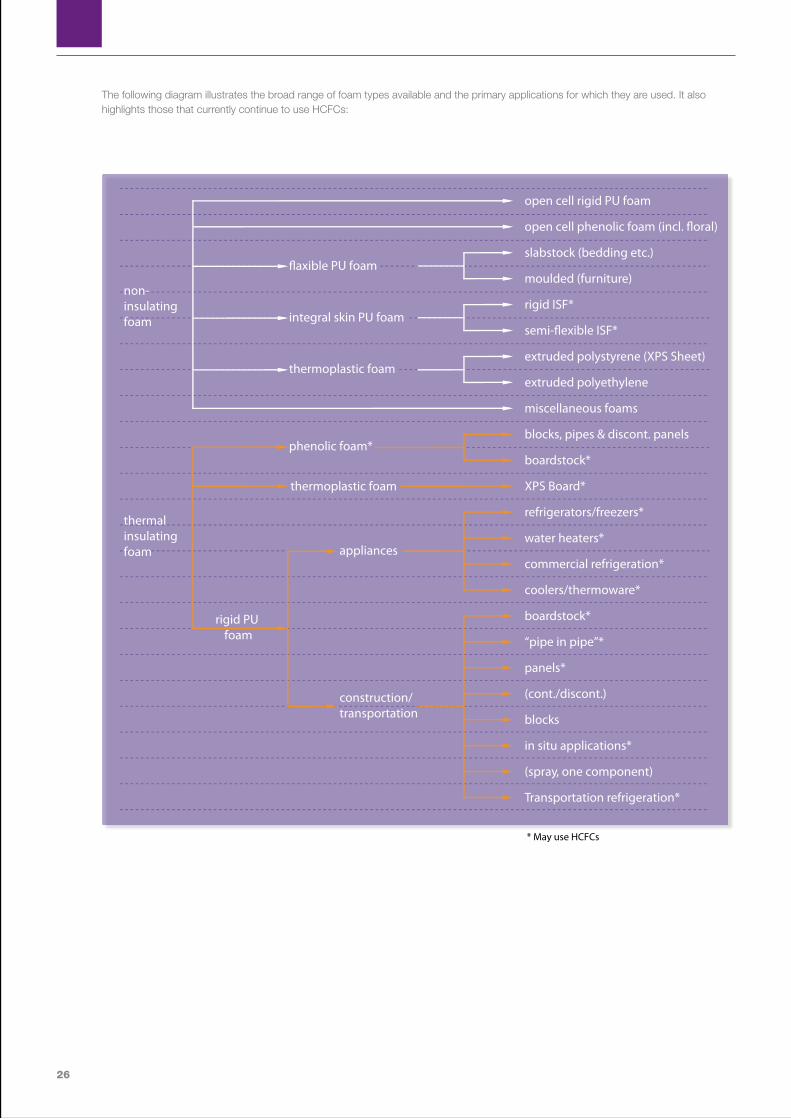
The following diagram illustrates the broad range of foam types available and the primary applications for which they are used. It also highlights those that currently continue to use HCFCs:
integral skin PU foam
�axible PU foam
thermoplastic foam
phenolic foam*
thermoplastic foam
construction/transportation
rigid PU foam
* May use HCFCs
open cell rigid PU foam
slabstock (bedding etc.)
moulded (furniture)
rigid ISF*
extruded polystyrene (XPS Sheet)
extruded polyethylene
miscellaneous foams
blocks, pipes & discont. panels
boardstock*
XPS Board*
refrigerators/freezers*
water heaters*
commercial refrigeration*
coolers/thermoware*
boardstock*
“pipe in pipe”*
panels*
(cont./discont.)
blocks
in situ applications*
(spray, one component)
Transportation refrigeration*
open cell phenolic foam (incl. �oral)
semi-�exible ISF*
appliances
non-insulating foam
thermalinsulating foam

27
UNEP DTIE Foam Sourcebook - 2010
Polyolefin (Polyethylene/Polypropylene) Foams Polyolefin foams are processed similarly to extruded polystyrene foams and have largely similar characteristics and applications. They have additional resilience in packaging applications and are often selected as the material of choice. Again polyolefin foams historically used CFCs and have progressed to other alternatives over the last 20 years.
Non-Foam Insulation Products A variety of non-foam products are used for thermal insulating purposes. Although this Sourcebook is focused on polymeric foams, it is important to understand that these co-exist with other insulation types in a competitive market, where changes in the cost-structure of foams can have consequences for market share. The most widespread product is mineral fibre, which can be based on spun rock (rock fibre) or glass (glass fibre). The low
density of these products makes them both inexpensive and comparable in embodied energy, despite the high energy intensity of the manufacturing process. However, since they rely on entrapped air for their thermal insulating properties they are losing ground against the more thermally efficient foamed products in many markets, particularly in chilled applications where moisture ingress can result in degradation of properties.
There are a number of other insulation materials available, often marketed on their apparent environmental credentials. These include naturally sourced materials such as sheep’s wool and recycled materials such as cellulose fibre. However, none of these products have broken through to the mass market.
There are also specialist insulation products such as calcium silicate, which is particularly good for high temperatures applications.
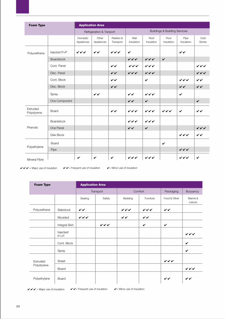
The following tables add to the earlier diagram in that, while they similarly relate the application areas with the type of foam, they also provide an indication of prevalence of use and a comparison with non-foam alternatives. They are based on an assessment generated for the IPCC/TEAP Special Report on Ozone and Climate . In this chapter, after a brief introduction on rigid foam and the role of the blowing agent, the different technology options will be reviewed by application.
28
Slabstock 4 4 4 4 4 4 4 4 4 4
Seating Safety Bedding Furniture Food & Other Marine & Leisure
Application Area
Moulded 4 4 4 4 4 4 4
Integral Skin 4 4 4 4 4
Injected/ P-I-P
4 4 4
Cont. Block 4
Spray 4
Sheet 4 4 4
Board 4 4 4
Board 4 4 4 4
Foam Type
Polyurethane
Extruded Polystyrene
Polyethylene
Transport Comfort Packaging Buoyancy
4 4 4 = Major use of insulation 4 4= Frequent use of insulation 4= Minor use of insulation
4 4 4 4 4 4 4 4 4 4 4
4 4 4 4 4 4 4 4 4 4 4
4 4 4 4 4 4 4
4 4 4 4 4 4 4 4
4 4 4 4 4 4 4 4
4 4 4 4 4 4 4 4 4 4 4
4 4 4 4 4 4
4 4 4 4
4 4 4 4 4 4 4 4 4 4 4 4 4 4
4 4 4 4 4 4
4 4 4 4 4 4
4 4 4 4 4
4
4 4 4
4 4 4 4 4 4 4 4 4 4 4 4 4
Domestic Appliances
Other Appliances
Reefers & Transport
Wall Insulation
Roof Insulation
Floor Insulation
Pipe Insulation
Cold Stores
Application AreaFoam Type
Polyurethane Injected P+P
Boardstock
Cont. Panel
Disc. Panel
Cont. Block
Disc. Block
Spray
One Component
Board
Boardstock
One Panel
Disk Block
Board
Pipe
Extruded Polystyrene
Phenolic
Polyethylene
Mineral Fibre
Refrigeration & Tranport Buildings & Building Services
4 4 4 = Major use of insulation 4 4= Frequent use of insulation 4= Minor use of insulation
29
UNEP DTIE Foam Sourcebook - 2010
4.2 Foam Manufacture and the Role of Blowing Agents Both tables shown in Section 4.1 give the first indication of the wide range of processes that are available for the processing of polymeric foams. The challenges relating to technology selection for each of these processes are covered in detail in Section 7. However, this section focuses primarily on the basic principles surrounding foam manufacture.
In general terms, a blowing agent is present in a foam formulation to ensure that the polymer matrix expands prior to solidifying. This expansion can be created by raising the temperature of the mix and causing the blowing agent to volatilise, or by reducing the pressure to which the mix is exposed (typical in extrusion processes), or a combination of both. The amount of blowing agent added and the processing conditions applied dictates the final density of the foams generated. For insulating foams, densities are typically in the range of 25-40 kg/m3. For packaging foams the densities will be lower and for comfort foams they will be lower still – often well below 20kg/m3.
Some products and processes lend themselves to the selection of blowing agents which are gaseous at room temperature. These are typically those products and processes in which expansion is controlled by pressure. In some cases, these types of processes are known as ‘froth foaming’, since the formulations froth when the pressure is released. Other processes rely on the blowing agent being in liquid form for the early stages of the process, with foam expansion and curing usually achieved by the application of heat. The following paragraphs use the example of polyurethane foam to illustrate the basic process involved.
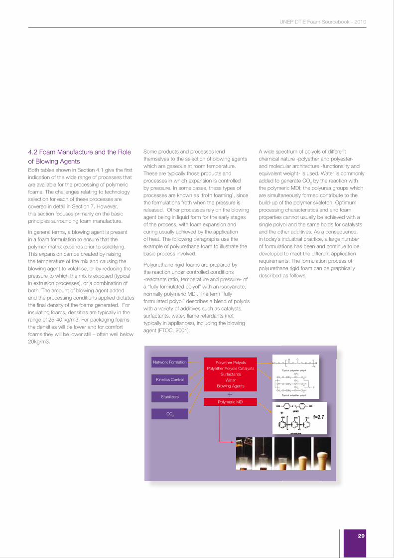
Polyurethane rigid foams are prepared by the reaction under controlled conditions -reactants ratio, temperature and pressure- of a “fully formulated polyol” with an isocyanate, normally polymeric MDI. The term “fully formulated polyol” describes a blend of polyols with a variety of additives such as catalysts, surfactants, water, flame retardants (not typically in appliances), including the blowing agent (FTOC, 2001).
A wide spectrum of polyols of different chemical nature -polyether and polyester- and molecular architecture -functionality and equivalent weight- is used. Water is commonly added to generate CO2 by the reaction with the polymeric MDI; the polyurea groups which are simultaneously formed contribute to the build-up of the polymer skeleton. Optimum processing characteristics and end foam properties cannot usually be achieved with a single polyol and the same holds for catalysts and the other additives. As a consequence, in today´s industrial practice, a large number of formulations has been and continue to be developed to meet the different application requirements. The formulation process of polyurethane rigid foam can be graphically described as follows:
Network Formation
+
Polyether PolyolsPolyether Polyols Catalysts
SurfactantsWater
Blowing Agents
Polymeric MDI
Kinetics Control
Stabilizers
CO2
30
No
Yes
No
Yes
No
No
Yes
No
Yes
Yes
Urethane Specific chemical link formed by the reaction of a hydroxyl (OH) with an isocyanate (NCO) group
TERM EXPLANATION APPLICATION MAY CONTAIN
BOWING AGENT
Polyurethane Polymer consisting of a multiple of urethane linkages formed from the reaction between a polyol and an isocyanate
To produce foams, elastomers, adhesives, sealants, coatings, and more
Isocyanate Family of chemicals with typically two or more NCO groups. Most common are MDI, P-MDI and TDI
As component in the manufacture of polyurethanes
Isocyanate prepolymer (also called polyurethane prepolymer)
Modified isocyanate by reacting excess of this substance with a polyol. Provides technical effects that cannot be obtained by unmodified ones
Main use is in flexible foam for moulding, MDI-based slabstock, elastomers, including shoe soles and integral skin foams and one component (”canister”) foams
(Base) Polyol Short chain chemical with two or more OH groups. Can be polyether (COC) or polyester (COOC) based
Used as a component by self-formulators, such as system houses, slabstock and rigid boardstock manufacturers
(Base)Polyol blend Blend of two or more base polyols Same as base polyol users, plus some appliance manufacturers
Blowing agent ubstance used to achieve a cellular (“foam”) structure
To produce rigid and flexible foams as well as expanded (micro-cellular) elastomers
Polyol formulation (also called formulated polyol)
Polyol or polyol blend plus catalyst(s), surfactant(s) plus sometimes other additives such as fire retardants
Larger polyurethane manufacturers, such as manufacturers of appliances and sandwich panels, who add blowing agent according to foaming conditions, including safety considerations
Fully formulated polyol As above, plus blowing agent Smaller polyurethane manufacturers, such as sprayfoam contractors, with relatively simple operating conditions
Polyurethane system Marketing term used to describe a generally two component package, consisting of an isocyanate and a fully formulated polyol
Same as fully formulated polyol
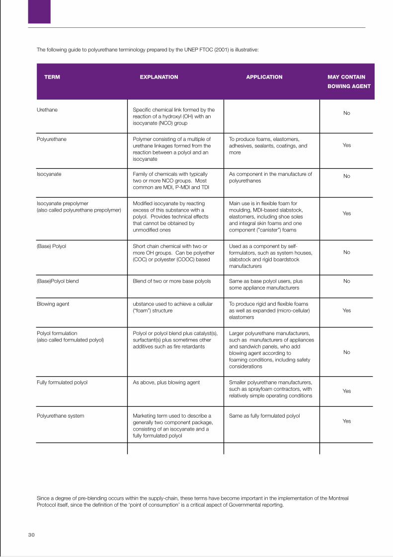
The following guide to polyurethane terminology prepared by the UNEP FTOC (2001) is illustrative:
Since a degree of pre-blending occurs within the supply-chain, these terms have become important in the implementation of the Montreal Protocol itself, since the definition of the ‘point of consumption’ is a critical aspect of Governmental reporting.
31
UNEP DTIE Foam Sourcebook - 2010
4.3 Where HCFC consumption occurs in the foam sector supply chain (polyols) When proposing foam sector projects for funding, it is important to understand the various related polyol definitions in order to accurately report the HCFC consumption related to the project and to make it consistent with national HCFC data reporting:
• Polyol: Short chain chemical with two or more OH groups.
• Polyol blend: Blend of two or more polyols.
• Formulated polyol: Polyol or polyol blend plus catalyst(s), surfactant(s) plus, in some cases, other additives such as fire retardants.
• Fully formulated polyol: Formulated polyol plus blowing agent.
• Polyurethane pre-polymer: Modified isocyanate by reacting excess of this substance with a polyol.
• Polyurethane system: Marketing term used to describe a generally two component package, consisting of an isocyanate and a fully formulated polyol.
Historically the Parties of the Montreal Protocol, when reporting to the Ozone Secretariat under the requirements of Article 7, have not necessarily considered CFCs or HCFCs contained in “fully formulated polyols” to be controlled substances. This has had consequences for data reporting and the establishment of national baselines. If the use (i.e. the point at which ODS finally cease to be controlled substances by becoming products or parts thereof) is consistently reported either at the point at which the “fully formulated polyol” is being created or where the “fully formulated polyols” are used, the consumption (production + imports - exports) figures are not distorted at the global level. The only time that “reported consumption” is distorted is where reporting practices are inconsistent and consumption is either double-counted or missed altogether. Accordingly, it is important that a consistent approach is adopted. This is also important when it comes to the appropriate allocation of funding along a supply chain.
Annex D to the Montreal Protocol itself makes reference to ‘pre-polymers’ as “products containing controlled substances”, while ‘polyurethane pre-polymers’ are described as “use systems to be considered as products” in Decision I/12. However, there is no explicit
suggestion that the Parties ever intended to cover fully formulated polyols under these references, nor would the relevant technical definitions support this. Accordingly, the Parties to the Protocol are currently reconsidering the implications of adopting a definition which sees fully formulated polyols as physical mixtures still containing controlled substances (ODS). Under these circumstances, trade in fully formulated polyols is still trade in mixtures containing controlled substances. This is fully consistent with the treatment of physical mixtures in decisions which have focused primarily on refrigerant blends (e.g. Decision XIV/7).
Since the significance of reporting practice to the establishing of national baselines and the allocation of funding for the projects came to light, some Article 5 countries have adopted the policy of reporting the import of ODS contained in “fully formulated polyols” as part of their baseline consumption, while others have stayed with the historical interpretation. The Executive Committee has made it clear that the phase-out of HCFC in fully formulated polyols can be eligible for funding provided that it is included in the HPMP and that the funding is proportionate to the processes being performed.

32
The goal of consistent future reporting will depend on further considerations by the Parties. The Parties are currently reviewing how to resolve this in such a way as to avoid double-counting at the same time as avoiding the omission of actual consumption in Article 7 reporting. Readers of this Sourcebook are encouraged to check with their National Ozone Unit on the reporting policy that is currently being adopted within their own countries in order to confirm that stated baselines in HPMPs properly reflect their uses and that the legitimate funding requirements for projects in the foam sector are met.
4.4 Reasons for Original Selection of CFCs and HCFCs For a large proportion of the foams in which ODS have been used historically, and particularly those in which HCFCs are currently used, the blowing agent has two principal functions:
1. The physical expansion of the foaming mixture to produce the desired foam density. In PU rigid foam the expansion is normally achieved by the combination of two mechanisms:
• the generation of CO2 as a consequence of the water/isocyanate reaction
and
• the evaporation of the blowing agent by the exothermically reaction mixture.
The boiling temperature of the blowing agent influences how these two mechanisms are combined in time, which strongly affects the foam ability to flow. Lower the boiling point, better the flow (KHUN, 1993). Immediately after the foam is produced there are usually two gases simultaneously present in the cells: carbon dioxide and the selected blowing agent (HCFC-141b, HFC-245fa, cyclo pentane, etc.).
2. Contribution to the thermal insulating performance of the foam. The blowing agent should remain in the closed celled foam and have a low gaseous thermal conductivity plus a low rate of diffusion through the foam (polymer matrix) so that the good insulating properties are retained for many years.
A number of publications have highlighted the preferable characteristics for a blowing agent. However, these have changed over time. Prior to the existing concerns over ozone depletion and climate change, the list would have appeared as follows:
• Physiologically non hazardous (low toxicity)
• Non flammable
• Chemically/physically stable
• Advantageous boiling point for ease of handling
• Good solubility in polyols (for polyurethane systems)
• Commercially available, and
• Economically viable.
As an additional set of characteristics for thermally insulating foams, the following were deemed as advantageous:
• Low gaseous thermal conductivity
• Boiling point to minimize condensation of the blowing agent in the final foam at operational temperatures
• Low solubility in the foam polymer to avoid matrix plasticisation which can cause dimensional stability problems.
• Low diffusion rate through the polymer matrix.
When the polymeric foam industry was emerging in the early 1960s, CFCs had already been in use as refrigerants within the refrigeration sector for some years. They were, therefore, relatively plentiful, inexpensive and offered virtually all of the characteristics listed above. In particular, the gaseous thermal conductivities of the substances were low, reflecting the thermodynamic properties that had also made them suitable as refrigerants. Coupled with low toxicity and chemical stability, CFC-11 and CFC-12 were seen as virtually designed-for-purpose and dominated the industry for 25 years. Of course, it was the chemical stability of CFCs which finally became their downfall.

33
UNEP DTIE Foam Sourcebook - 2010
When, in 1974, Rowland and Molina made the first linkage between ozone depletion and chlorine in the stratosphere, few, if any, from the polymeric foams industry were watching developments. However, the discovery of the Antarctic ozone hole in 1985 added urgency to the debate and began to implicate the foam industry, both in flexible and in rigid products.
As the industry began to look for immediate alternative blowing agents, it was already known that very few, if any, alternatives could provide the package of characteristics displayed by the CFCs.
HCFC-22 was already well established as a refrigerant in the commercial refrigeration sector and it was known that the presence of the hydrogen atom in the molecule reduced the stability and resulting atmospheric lifetime of the substance somewhat. However, its boiling point was inappropriate for a large section of the industry, and, even where it wasn’t (e.g. extruded polystyrene), the molecule was found to permeate the cell walls too quickly. This situation therefore led to the search for alternative HCFCs that could fulfil the same role as CFCs with less likely damage on the environment.
Out of that work, three additional HCFCs emerged: - HCFC-123, HCFC-141b and HCFC-142b. For a long period, HCFC-123 looked like the ideal replacement for CFC-11, having a very low ozone depletion potential of 0.012 – i.e. nearly 100 times lower than CFC-11 (ODP = 1). However, late in the development phase, it was discovered that the toxicity of the substance could be of concern. This led to the later introduction of HCFC-141b as the CFC-11 replacement of choice, even though its ozone depletion potential was significantly higher at 0.11 (i.e. less than ten times lower than CFC-11). HCFC-142b was used alongside HCFC-22 in the extruded polystyrene and polyolefin foam sectors, since the HCFC-142b component, whilst more expensive than HCFC-22, provided the thermal performance that the foams required, because it did not diffuse through the cell walls quickly.
These early experiences of blowing agent transition taught a number of lessons. Firstly, the HCFC-123 experience taught that an alternative, no matter how attractive in other respects, could not be used if a critical parameter was unacceptable. In the case of
HCFC-141b and HCFC-142b, the industry learned that variable parameters such as ODP or cost can be compromised to a degree in order to maintain the primary performance characteristics of the product itself – in this case thermal insulation performance.
Nevertheless, it became increasingly clear, in the early 1990s, as the legislators caught up with the pace of technology development that these were only going to be seen as ‘transitional’ solutions, despite the fact that they were seen as part of the solution rather than part of the problem. Therefore the search for further alternatives could not be halted.
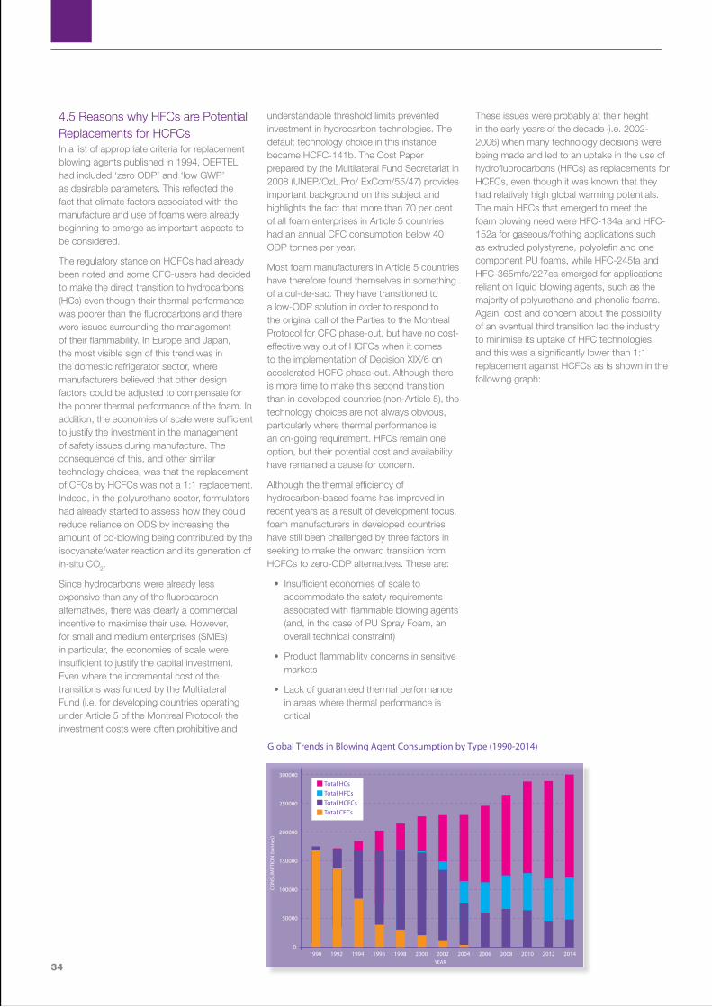
34
4.5 Reasons why HFCs are Potential Replacements for HCFCs In a list of appropriate criteria for replacement blowing agents published in 1994, OERTEL had included ‘zero ODP’ and ‘low GWP’ as desirable parameters. This reflected the fact that climate factors associated with the manufacture and use of foams were already beginning to emerge as important aspects to be considered.
The regulatory stance on HCFCs had already been noted and some CFC-users had decided to make the direct transition to hydrocarbons (HCs) even though their thermal performance was poorer than the fluorocarbons and there were issues surrounding the management of their flammability. In Europe and Japan, the most visible sign of this trend was in the domestic refrigerator sector, where manufacturers believed that other design factors could be adjusted to compensate for the poorer thermal performance of the foam. In addition, the economies of scale were sufficient to justify the investment in the management of safety issues during manufacture. The consequence of this, and other similar technology choices, was that the replacement of CFCs by HCFCs was not a 1:1 replacement. Indeed, in the polyurethane sector, formulators had already started to assess how they could reduce reliance on ODS by increasing the amount of co-blowing being contributed by the isocyanate/water reaction and its generation of in-situ CO2.
Since hydrocarbons were already less expensive than any of the fluorocarbon alternatives, there was clearly a commercial incentive to maximise their use. However, for small and medium enterprises (SMEs) in particular, the economies of scale were insufficient to justify the capital investment. Even where the incremental cost of the transitions was funded by the Multilateral Fund (i.e. for developing countries operating under Article 5 of the Montreal Protocol) the investment costs were often prohibitive and
understandable threshold limits prevented investment in hydrocarbon technologies. The default technology choice in this instance became HCFC-141b. The Cost Paper prepared by the Multilateral Fund Secretariat in 2008 (UNEP/OzL.Pro/ ExCom/55/47) provides important background on this subject and highlights the fact that more than 70 per cent of all foam enterprises in Article 5 countries had an annual CFC consumption below 40 ODP tonnes per year.
Most foam manufacturers in Article 5 countries have therefore found themselves in something of a cul-de-sac. They have transitioned to a low-ODP solution in order to respond to the original call of the Parties to the Montreal Protocol for CFC phase-out, but have no cost-effective way out of HCFCs when it comes to the implementation of Decision XIX/6 on accelerated HCFC phase-out. Although there is more time to make this second transition than in developed countries (non-Article 5), the technology choices are not always obvious, particularly where thermal performance is an on-going requirement. HFCs remain one option, but their potential cost and availability have remained a cause for concern.
Although the thermal efficiency of hydrocarbon-based foams has improved in recent years as a result of development focus, foam manufacturers in developed countries have still been challenged by three factors in seeking to make the onward transition from HCFCs to zero-ODP alternatives. These are:
• Insufficient economies of scale to accommodate the safety requirements associated with flammable blowing agents (and, in the case of PU Spray Foam, an overall technical constraint)
• Product flammability concerns in sensitive markets
• Lack of guaranteed thermal performance in areas where thermal performance is critical
These issues were probably at their height in the early years of the decade (i.e. 2002-2006) when many technology decisions were being made and led to an uptake in the use of hydrofluorocarbons (HFCs) as replacements for HCFCs, even though it was known that they had relatively high global warming potentials. The main HFCs that emerged to meet the foam blowing need were HFC-134a and HFC-152a for gaseous/frothing applications such as extruded polystyrene, polyolefin and one component PU foams, while HFC-245fa and HFC-365mfc/227ea emerged for applications reliant on liquid blowing agents, such as the majority of polyurethane and phenolic foams. Again, cost and concern about the possibility of an eventual third transition led the industry to minimise its uptake of HFC technologies and this was a significantly lower than 1:1 replacement against HCFCs as is shown in the following graph:
0
50000
100000
150000
200000
250000
300000
1990 1992 1994 1996 1998 2000 2002 2004 2006 2008 2010 20142012
!
YEAR
Total HCsTotal HFCsTotal HCFCsTotal CFCs
CON
SUM
PTIO
N (t
onne
s)
Global Trends in Blowing Agent Consumption by Type (1990-2014)

35
UNEP DTIE Foam Sourcebook - 2010
4.6 Why HFCs can be Sub-optimal Solutions for Climate Recent analysis has shown that HFCs are being used in a variety of foam technologies globally, these include, but are not limited to:
• PU Steel-faced panels (both continuously and discontinuously produced)
• PU Spray Foam
• Extruded polystyrene foams (XPS)
• PU Integral Skin foams and Shoe Soles
• PU Appliance Foam (particularly in North America)
Section 3 of this Guidance has already provided an overview of the factors to be considered when evaluating the climate impact of technologies and making comparisons between them. One of the lessons to be drawn from such analyses is that climate impact is driven by emissions and not technology choice per se. Therefore, it is important to ensure that, when considering the use of HFCs, due account is taken of any measures that may be implemented across the lifecycle of the product to limit emissions. For foams, this could include capture of blowing agents during the production process or end-of-life management provisions.
The use of HFCs could therefore be justified on an on-going basis if it could be guaranteed that emissions were largely avoided from all phases of the lifecycle. Equally, there would be a case for the on-going use of HFCs if the incremental energy efficiency advantages could be quantified and would result in the lower level of overall greenhouse gas emissions, when corrected for the appropriate global warming potential of the HFCs used. To make this judgement, it is necessary to have access to the comparative impacts of different blowing agent types. Although this is covered further in the next Section, the following Table extracted from the IPCC/TEAP Special Report on Ozone and Climate is likely to be helpful at this juncture:
Apart from the global warming potential of the blowing agent itself, one of the other factors that needs to be considered alongside the energy efficiency assessment is the carbon intensity of the fuels used to heat and/or cool. This can be particularly important where electrical heating/cooling is applied routinely, since it will be the fuel used to generate the power that will count in this case.
Assessing the applications listed earlier in which HFCs are being used currently, it can be seen that the use in PU integral skin and shoe soles might be the hardest to defend on climate grounds, since they are totally emissive and the use of HFCs does not contribute to any thermal benefit..
For the thermal insulation products, the case might be greater, although the relative high emissions associated the extruded polystyrene foam manufacturing process (see the IPCC table below) makes the case harder to justify, particularly when HFC-134a is the blowing agent of choice, since this has a GWP of 1410.
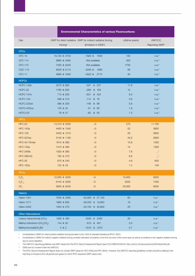
36
Gas GWP for direct radiative GWP for indirect radiative forcing Lifetime (years) UNFCCC
forcinga (Emission in 2005b) Reporting GWPc
CFCs
CFC-12 10,720 ± 3750 -1920 ± 1630 100 n.a.d
CFC-114 9880 ± 3460 Not available 300 n.a.d
CFC-115 7250 ± 2540 Not available 1700 n.a.d
CGC-113 6030 ± 2110 -2250 ± 1890 85 n.a.d
CFC-11 4680 ± 1640 -3420 ± 2710 45 n.a.d
HCFCs
HCFC-142b 2270 ±800 -337 ± 237 17.9 n.a.d
HCFC-22 1780 ± 620 -269 ± 183 12 n.a.d
HCFC-141b 713 ± 250 -631 ± 424 9.3 n.a.d
HCFC-124 599 ± 210 -114 ± 76 2.8 n.a.d
HCFC-225cb 586 ± 205 -148 ± 98 5.8 n.a.d
HCFC=225ca 120 ± 42 -91 ± 60 1.9 n.a.d
HCFC123 76 ± 27 -82 ± 55 1.3 n.a.d
HFCs
HFC-23 14,310 ± 5000 ~0 270 11,700
HFC-143a 4400 ± 1540 ~0 52 3800
HFC-125 3450 ± 1210 ~0 29 2800
HFC-227ea 3140 ± 1100 ~0 34.2 2900
HFC-43-10mee 1610 ± 560 ~0 15.9 1300
HFC-134a 1410 ± 490 ~0 14 1300
HFC-245fa 1020 ± 360 ~0 7.6 _c
HFC-365mfc 782 ± 270 ~0 8.6 _c
HFC-32 670 ± 240 ~0 4.9 650
HFC-152a 122 ± 43 ~0 1.4 140
PFCs
C2F6 12,000 ± 4200 ~0 10,000 9200
C6F14 9140 ± 3200 ~0 3200 7400
CF4 5820 ± 2040 ~0 50,000 6500
Halons
Halon-1301 7030 ± 2460 -32,900 ± 27,100 65 n.a.d
Halon-1211 1860 ± 650 -28,200 ± 19,600 16 n.a.d
Halon-2402 1620 ± 570 -43,100 ± 30,800 20 n.a.d
Other Halocarbons
Carbon tetrachloride (CCl4) 1380 ± 480 -3330 ± 2460 26 n.a.d
Methyl chloroform (CH3CCl3) 144 ± 50 -610 ± 407 5.0 n.a.d
Methyl bromide(CH3Br) 5 ± 2 -1610 ± 1070 0.7 n.a.d
a Uncertainties in GWPs for direct positive radiative forcing are taken to be +35% (2 standard deviations) (IPCC, 2001).b Uncertainties in GWPs for indirect negative radiative forcing consider estimated uncertainty in the time recovery of the ozone layer as well as uncertainty in the negative radiative forcing
due to ozone depletion.c The UNFCCC reporting guidelines use GWP values from the IPCC Seconf Assessment Report (see FCCC/SBSTA/2004/8, http://unfccc.int/resource/docs/2004/sbsta/08.pdf).d ODSs are not covered under the UNFCCC.e The IPCC Second Assessment Report does not contain GWP values for HFC-245fa and HFC-36mfc. However, the UNFCCC reporting guidelines contain provisions relating to the
reporting of emissions from all greenhouse gases for which IPCC-assessed GWP values exist.
Environmental Characteristics of various Fluorocarbons

37
UNEP DTIE Foam Sourcebook - 2010
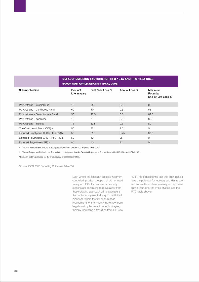
38
Even where the emission profile is relatively controlled, product groups that do not need to rely on HFCs for process or property reasons are continuing to move away from these blowing agents. A prime example is the continuous panel industry in the United Kingdom, where the fire performance requirements of the industry have now been largely met by hydrocarbon technologies, thereby facilitating a transition from HFCs to
HCs. This is despite the fact that such panels have the potential for recovery and destruction and end-of-life and are relatively non-emissive during their other life cycle phases (see the IPCC table above)
Sub-Application Product First Year Loss % Annual Loss % Maximum Life in years Potential End-of-Life Loss %
Polyurethane – Integral Skin 12 95 2.5 0
Polyurethane – Continuous Panel 50 10 0.5 65
Polyurethane – Discontinuous Panel 50 12.5 0.5 62.5
Polyurethane – Appliance 15 7 0.5 85.5
Polyurethane – Injected 15 12.5 0.5 80
One Component Foam (OCF) a 50 95 2.5 0
Extruded Polystyrene (XPS)b - HFC-134a 50 25 0.75 37.5
Extruded Polystyrene (XPS) - HFC-152a 50 50 25 0
Extruded Polyethylene (PE) a 50 40 3 0
a Source: [Ashford and Jeffs, ETF, 2004] assembled from UNEP FTOC Reports 1998, 2002.
b Vo and Paquet: An Evaluation of Thermal Conductivity over time for Extruded Polystyrene Foams blown with HFC-134a and HCFC-142b
* Emission factors predicted for the products and processes identified.
Source: IPCC 2006 Reporting Guidelines Table 7.6
DEFAULT EMISSION FACTORS FOR HFC-134A AND HFC-152A USES
(FOAM SUB-APPLICATIONS ) (IPCC, 2005)
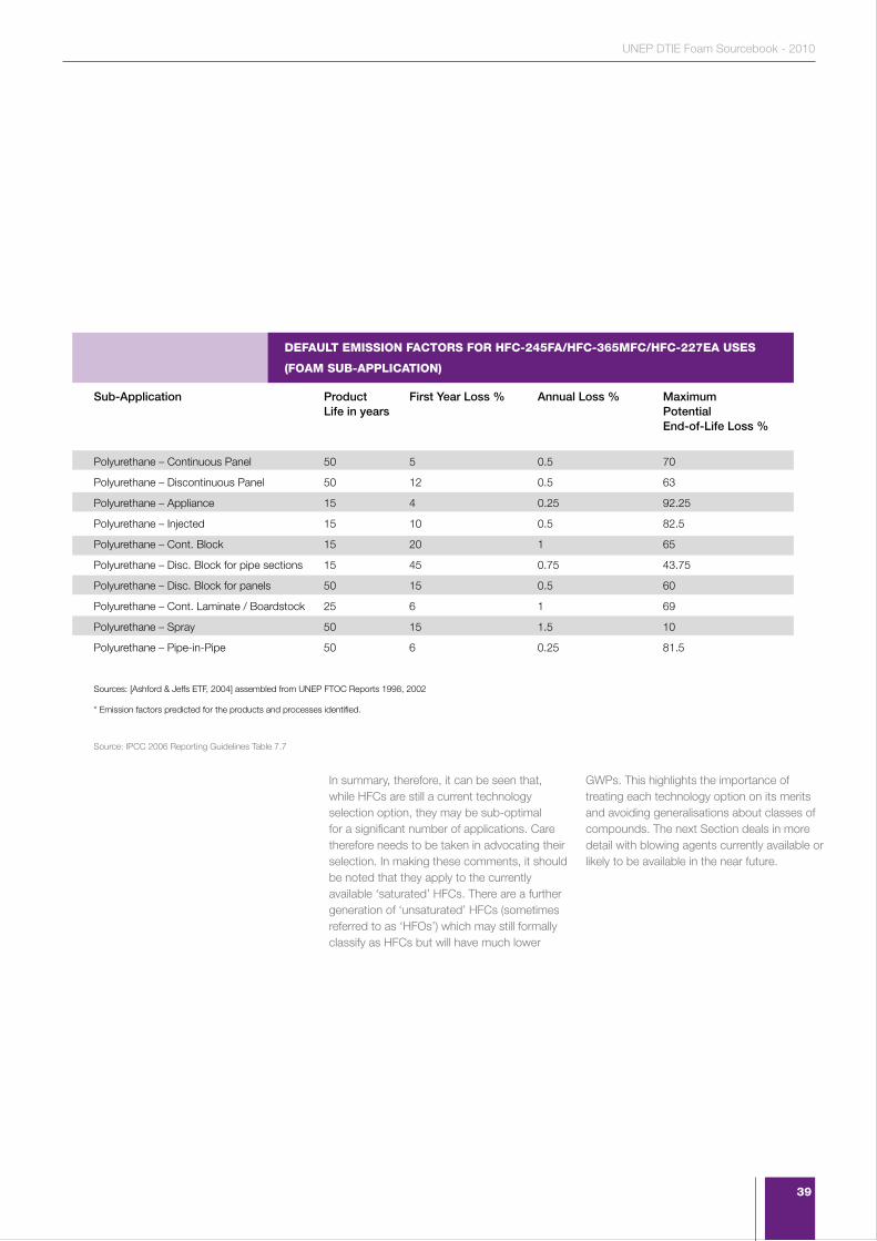
39
UNEP DTIE Foam Sourcebook - 2010
In summary, therefore, it can be seen that, while HFCs are still a current technology selection option, they may be sub-optimal for a significant number of applications. Care therefore needs to be taken in advocating their selection. In making these comments, it should be noted that they apply to the currently available ‘saturated’ HFCs. There are a further generation of ‘unsaturated’ HFCs (sometimes referred to as ‘HFOs’) which may still formally classify as HFCs but will have much lower
GWPs. This highlights the importance of treating each technology option on its merits and avoiding generalisations about classes of compounds. The next Section deals in more detail with blowing agents currently available or likely to be available in the near future.
Sub-Application Product First Year Loss % Annual Loss % Maximum Life in years Potential End-of-Life Loss %
Polyurethane – Continuous Panel 50 5 0.5 70
Polyurethane – Discontinuous Panel 50 12 0.5 63
Polyurethane – Appliance 15 4 0.25 92.25
Polyurethane – Injected 15 10 0.5 82.5
Polyurethane – Cont. Block 15 20 1 65
Polyurethane – Disc. Block for pipe sections 15 45 0.75 43.75
Polyurethane – Disc. Block for panels 50 15 0.5 60
Polyurethane – Cont. Laminate / Boardstock 25 6 1 69
Polyurethane – Spray 50 15 1.5 10
Polyurethane – Pipe-in-Pipe 50 6 0.25 81.5
Sources: [Ashford & Jeffs ETF, 2004] assembled from UNEP FTOC Reports 1998, 2002
* Emission factors predicted for the products and processes identified.
Source: IPCC 2006 Reporting Guidelines Table 7.7
DEFAULT EMISSION FACTORS FOR HFC-245FA/HFC-365MFC/HFC-227EA USES
(FOAM SUB-APPLICATION)
40
Section 5.General review of alternative blowing agents
“Alternatives exist for all current HCFC applications and the majority of these have low global warming potentials”
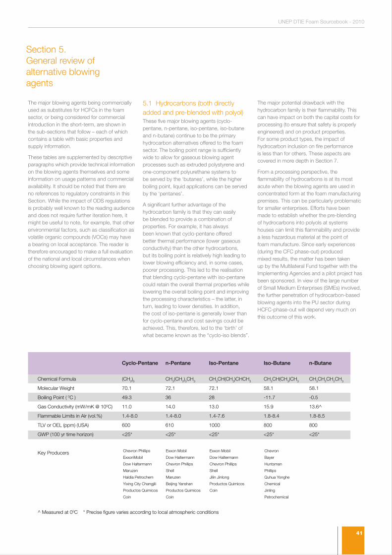
41
UNEP DTIE Foam Sourcebook - 2010
The major blowing agents being commercially used as substitutes for HCFCs in the foam sector, or being considered for commercial introduction in the short-term, are shown in the sub-sections that follow – each of which contains a table with basic properties and supply information.
These tables are supplemented by descriptive paragraphs which provide technical information on the blowing agents themselves and some information on usage patterns and commercial availability. It should be noted that there are no references to regulatory constraints in this Section. While the impact of ODS regulations is probably well known to the reading audience and does not require further iteration here, it might be useful to note, for example, that other environmental factors, such as classification as volatile organic compounds (VOCs) may have a bearing on local acceptance. The reader is therefore encouraged to make a full evaluation of the national and local circumstances when choosing blowing agent options.
5.1 Hydrocarbons (both directly added and pre-blended with polyol)These five major blowing agents (cyclo-pentane, n-pentane, iso-pentane, iso-butane and n-butane) continue to be the primary hydrocarbon alternatives offered to the foam sector. The boiling point range is sufficiently wide to allow for gaseous blowing agent processes such as extruded polystyrene and one-component polyurethane systems to be served by the ‘butanes’, while the higher boiling point, liquid applications can be served by the ‘pentanes’.
A significant further advantage of the hydrocarbon family is that they can easily be blended to provide a combination of properties. For example, it has always been known that cyclo-pentane offered better thermal performance (lower gaseous conductivity) than the other hydrocarbons, but its boiling point is relatively high leading to lower blowing efficiency and, in some cases, poorer processing. This led to the realisation that blending cyclo-pentane with iso-pentane could retain the overall thermal properties while lowering the overall boiling point and improving the processing characteristics – the latter, in turn, leading to lower densities. In addition, the cost of iso-pentane is generally lower than for cyclo-pentane and cost savings could be achieved. This, therefore, led to the ‘birth’ of what became known as the “cyclo-iso blends”.
The major potential drawback with the hydrocarbon family is their flammability. This can have impact on both the capital costs for processing (to ensure that safety is properly engineered) and on product properties. For some product types, the impact of hydrocarbon inclusion on fire performance is less than for others. These aspects are covered in more depth in Section 7.
From a processing perspective, the flammability of hydrocarbons is at its most acute when the blowing agents are used in concentrated form at the foam manufacturing premises. This can be particularly problematic for smaller enterprises. Efforts have been made to establish whether the pre-blending of hydrocarbons into polyols at systems houses can limit this flammability and provide a less hazardous material at the point of foam manufacture. Since early experiences (during the CFC phase-out) produced mixed results, the matter has been taken up by the Multilateral Fund together with the Implementing Agencies and a pilot project has been sponsored. In view of the large number of Small Medium Enterprises (SMEs) involved, the further penetration of hydrocarbon-based blowing agents into the PU sector during HCFC-phase-out will depend very much on this outcome of this work.
Cyclo-Pentane n-Pentane Iso-Pentane Iso-Butane n-Butane
Chemical Formula (CH2)5 CH3(CH2)3CH3 CH3CH(CH3)CHCH3 CH3CH(CH3)CH3 CH3CH2CH2CH3
Molecular Weight 70.1 72.1 72.1 58.1 58.1
Boiling Point ( 0C ) 49.3 36 28 -11.7 -0.5
Gas Conductivity (mW/mK @ 100C) 11.0 14.0 13.0 15.9 13.6^
Flammable Limits in Air (vol.%) 1.4-8.0 1.4-8.0 1.4-7.6 1.8-8.4 1.8-8.5
TLV or OEL (ppm) (USA) 600 610 1000 800 800
GWP (100 yr time horizon) <25* <25* <25* <25* <25*
Key Producers
^ Measured at 00C * Precise figure varies according to local atmospheric conditions
Chevron Phillips
ExxonMobil
Dow Haltermann
Maruzen
Haldia Petrochem
Yixing City Changjili
Productos Quimicos
Coin
Exxon Mobil
Dow Haltermann
Chevron Phillips
Shell
Maruzen
Beijing Yanshan
Productos Quimicos
Coin
Exxon Mobil
Dow Haltermann
Chevron Phillips
Shell
Jilin Jinlong
Productos Quimicos
Coin
Chevron
Bayer
Huntsman
Phillips
Quhua Yonghe
Chemical
Jinling
Petrochemical
Section 5. General review of alternative blowing agents
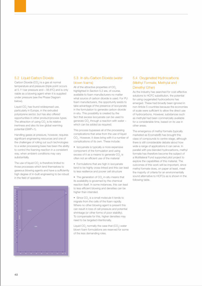
42
5.2 Liquid Carbon DioxideCarbon Dioxide (CO2) is a gas at normal temperature and pressure (triple point occurs at 5.11 bar pressure and – 56.60C) and is only viable as a blowing agent when it is supplied under pressure (see the Phase Diagram below).
Liquid CO2 has found widespread use, particularly in Europe, in the extruded polystyrene sector, but has also offered opportunities in other product/process types. The attraction of using CO2 is its relative inertness and also its low global warming potential (GWP=1).
Handling gases at pressure, however, requires significant engineering resources and one of the challenges of rolling out such technologies to a wider processing base has been the ability to control the foaming reaction in a consistent way, when ambient conditions may vary substantially.
The use of liquid CO2 is therefore limited to those processes which lend themselves to gaseous blowing agents and have a sufficiently high degree of in-built engineering to be robust in the field of operation.
5.3 In-situ Carbon Dioxide (water blown foams)All of the attractive properties of CO2 highlighted in Section 5.2 are, of course, available to foam manufacturers no matter what source of carbon dioxide is used. For PU foam manufacturers, the opportunity exists to take advantage of the presence of isocyanate in the formulation to generate carbon dioxide in-situ. This possibility is created by the fact that excess isocyanate can be used to generate CO2 through a reaction with water – which can be added as required.
This process bypasses all of the processing complications that arise from the use of liquid CO2. However, it does bring with it a number of complications of its own. These include:
• Isocyanate is typically a more expensive component of the formulation and using excess of it as a means to generate CO2 is often not an efficient use of the material
• Formulations that are high in isocyanate tend to be highly cross-linked and this can lead to less resilience and poorer cell structure
• The generation of CO2 in-situ means that its availability is governed by the chemical reaction itself. In some instances, this can lead to less efficient blowing and densities can be higher than intended.
• Since CO2 is a small molecule it tends to migrate from the cells of the foam rapidly. Where no other blowing agent is present this can result in loss of cell pressure and potential shrinkage (or other forms of poor stability). To compensate for this, higher densities may need to be targeted intentionally.
Liquid CO2 normally the case that (CO2) water blown foam formulations are reserved for some of the less demanding roles.
5.4 Oxygenated Hydrocarbons (Methyl Formate, Methylal and Dimethyl Ether)As the industry has searched for cost-effective solutions to HCFC substitution, the potential for using oxygenated hydrocarbons has emerged. These had broadly been ignored in non-Article 5 countries because the economies of scale were sufficient to allow the direct use of hydrocarbons. However, substances such as methylal had been commercially available for a considerable time, based on its use in other areas.
The emergence of methyl formate (typically marketed as Ecomate®) has brought this class of compounds to centre-stage, although there is still considerable debate about how wide a range of applications it can serve. In parallel with pre-blended hydrocarbons, methyl formate has therefore become the subject of a Multilateral Fund supported pilot project to explore the capabilities of this material. The outcomes of this work will be important, since methyl formate does, on paper at least, meet the majority of criteria for an environmentally sound alternative to HCFCs as is shown in the following table.
+20+100-10-20-30-40-50-60
1
2
3
4
5
6
789
10
20
30
40
50
60
708090
100
P (atmos)
C
PC
0
Cooking Oil and TallowOilseed Rape (UK)
Oilseed Rape (Ukraine)Oilseed Rape (Poland)
Oilseed Rape (Germany)Oilseed Rape (France)
Oilseed Rape (Finland)Oilseed Rape (Canada)
Oilseed Rape (Australia)Soy (USA)
Soy (Brasil)Soy (Argentina)
Palm Oil (Malaysia)Palm Oil (Indonesia)
Natural GasDiesel
GasolineCoal
GAS
PT
LIQUID
SOLID
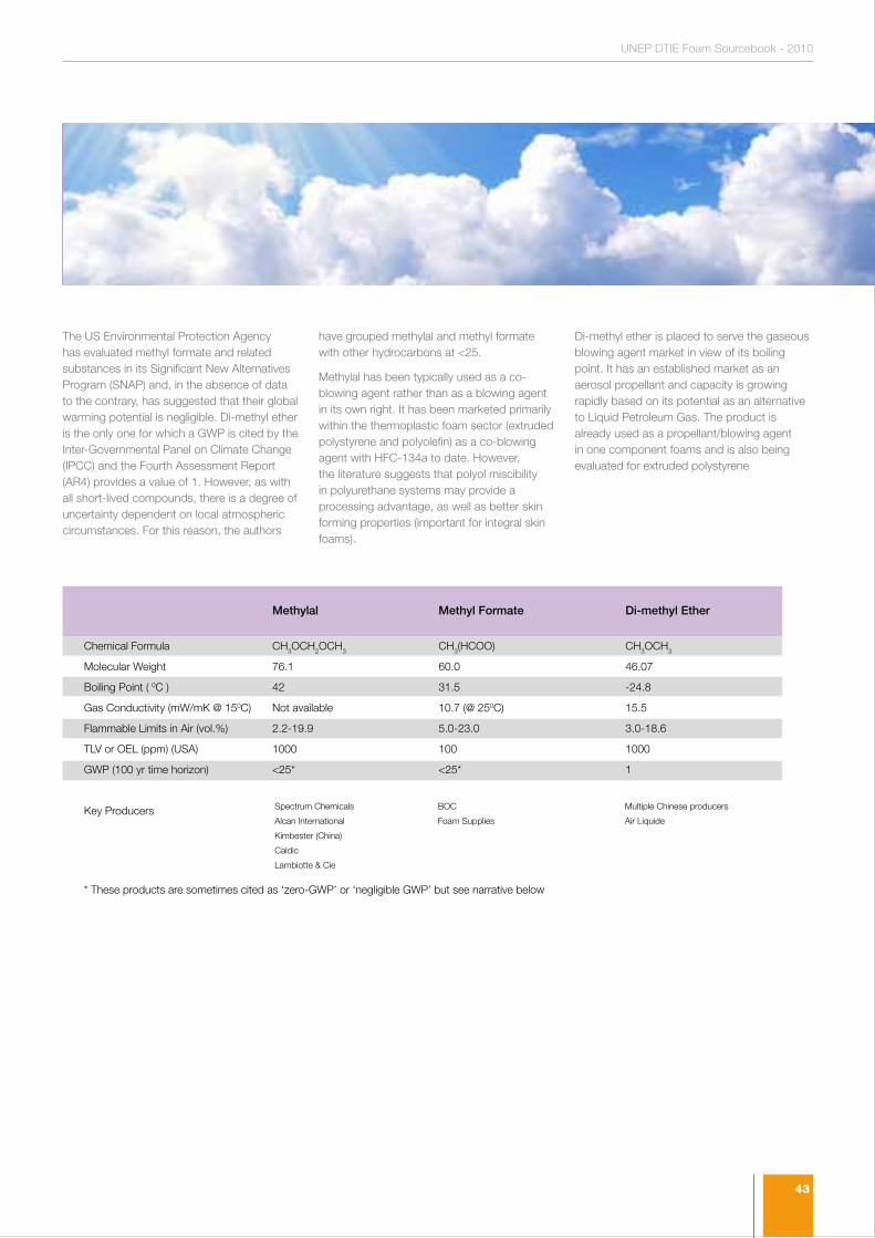
43
UNEP DTIE Foam Sourcebook - 2010
The US Environmental Protection Agency has evaluated methyl formate and related substances in its Significant New Alternatives Program (SNAP) and, in the absence of data to the contrary, has suggested that their global warming potential is negligible. Di-methyl ether is the only one for which a GWP is cited by the Inter-Governmental Panel on Climate Change (IPCC) and the Fourth Assessment Report (AR4) provides a value of 1. However, as with all short-lived compounds, there is a degree of uncertainty dependent on local atmospheric circumstances. For this reason, the authors
have grouped methylal and methyl formate with other hydrocarbons at <25.
Methylal has been typically used as a co-blowing agent rather than as a blowing agent in its own right. It has been marketed primarily within the thermoplastic foam sector (extruded polystyrene and polyolefin) as a co-blowing agent with HFC-134a to date. However, the literature suggests that polyol miscibility in polyurethane systems may provide a processing advantage, as well as better skin forming properties (important for integral skin foams).
Di-methyl ether is placed to serve the gaseous blowing agent market in view of its boiling point. It has an established market as an aerosol propellant and capacity is growing rapidly based on its potential as an alternative to Liquid Petroleum Gas. The product is already used as a propellant/blowing agent in one component foams and is also being evaluated for extruded polystyrene
Methylal Methyl Formate Di-methyl Ether
Chemical Formula CH3OCH2OCH3 CH3(HCOO) CH3OCH3
Molecular Weight 76.1 60.0 46.07
Boiling Point ( 0C ) 42 31.5 -24.8
Gas Conductivity (mW/mK @ 150C) Not available 10.7 (@ 250C) 15.5
Flammable Limits in Air (vol.%) 2.2-19.9 5.0-23.0 3.0-18.6
TLV or OEL (ppm) (USA) 1000 100 1000
GWP (100 yr time horizon) <25* <25* 1
Key Producers
* These products are sometimes cited as ‘zero-GWP’ or ‘negligible GWP’ but see narrative below
Spectrum Chemicals
Alcan International
Kimbester (China)
Caldic
Lambiotte & Cie
BOC
Foam Supplies
Multiple Chinese producers
Air Liquide
44
5.5 Chlorinated Hydrocarbons (Methylene Chloride, Trans-1,2 di-chloroethylene and 2-chloropropane)Methylene Chloride became a widely used substitute for CFCs as an auxiliary blowing agent in flexible and moulded polyurethane foams throughout the 1990s. However, there remains some debate about the health effects of methylene chloride exposure which has led to significant regional variations in uptake. The primary area of contention has been the potential of methylene chloride as a carcinogen. This has led to slightly differing treatments in North America and Europe with the latter tending to be more conservative in its approach. The need for care in managing exposure is reflected in the relatively low threshold limit value (TLV) range of 35-100 ppm.
Although, methylene chloride is well established as an auxiliary blowing agent, its use, in general, is on the decline. The full characteristics of methylene chloride, trans-1,2-dichloroethylene and 2-chloropropane are shown in the following table.
In similar fashion to methylal, trans-1,2-dichloroethylene has not been used significantly as a blowing agent in its own right, but has tended to be used as a co-blowing agent in order to modify the processing characteristics of other blowing agents. It has found a particular niche in modifying the froth foaming behaviour of HFC-134a and HFC-245fa, as well as enhancing the blowing efficiency of these materials.
2-chloropropane (also known as iso-propyl chloride) has been used only to a limited extent as a blowing agent. Most notably it has found use in the manufacture of phenolic foams in Europe for some years. It is understood that preliminary evaluation has also occurred in polyurethane foam systems, although the outcome of tat work is not known.
Despite their chlorine content, all three of these compounds, and many like them, escape from consideration under the Montreal Protocol because of their very short atmospheric lifetimes which make it that the respective molecules do not reach the stratosphere and trigger ozone depletion. However, as with all short-lived halogenated substances, care needs to be taken to evaluate the impact of breakdown products created in the troposphere
Methylene Chloride Trans-1,2-dichloroethylene 2-chloropropane
Chemical Formula CH2Cl2 ClHC=CHCl CH3CHClCH3
Molecular Weight 84.9 97 78.5
Boiling Point ( 0C ) 40 48 35.7
Gas Conductivity (mW/mK @ 100C) Not available Not available Not available
Flammable Limits in Air (vol.%) None 6.7-18 2.8-10.7
TLV or OEL (ppm) (USA) 35-100 200 50
GWP (100 yr time horizon) Not available <25 Not available
Key Producers
* These products are sometimes cited as ‘zero-GWP’ or ‘negligible GWP’ but see narrative below
Multiple Sources Arkema Alfa Aesar
45
UNEP DTIE Foam Sourcebook - 2010
5.6 Saturated HFCsThe case for and against the use of saturated HFCs has already been covered substantially in Sections 4.5 and 4.6 of this Sourcebook. Although uptake has been less in developed countries than had been anticipated by a number of stakeholders, the potential for their use in developing countries remains very real and potentially damaging to efforts to reduce climate impact through the early phase-out of HCFCs. The following table illustrates the specific characteristics of the commonly available HFCs and indicates that the range of boiling-points is sufficient to meet most of the requirements of the foam manufacturing industry.
HFC-227ea is seldom used on its own for foam-blowing purposes, but is usually co-blended with HFC-365mfc at varying levels to modify the flammability characteristics of the latter. Similarly, HFC-152a is normally used as a co-blowing agent with HFC-134a in order to enhance blowing efficiency. However, despite its relatively low GWP, its partial flammability and high cell wall permeability make it less suitable as a blowing agent on its own. There is some recorded use of HFC-152a on its own in XPS, but this is only where long-term thermal performance is less critical
As noted in Section 4.5, there has been a strong tendency in polyurethane foam sectors to co-blow HFC-based foams with CO2 (water) by taking advantage of the isocyanate/water reaction. This can offset the increased cost of HFCs, but the magnitude of the offset
does depend considerably on the price of isocyanate prevailing at the time. In addition, the co-blowing strategy does reduce the potential impact of the direct emissions of blowing agent from the foam.
HFC-134a HFC-152a HFC-245fa HFC-365mfc HFC-227ea
Chemical Formula CH2FCF3 CHF2CH3 CF3CH2 CHF2 CF3CH2 CF2 CH3 CF3CHF CF3
Molecular Weight 102 66 134 148 170
Boiling Point ( 0C ) -27 -25 15.3 40.2 -16.5
Gas Conductivity (mW/mK @ 100C) 12.4 14.3* 12.5* 10.6* 11.6
Flammable Limits in Air (vol.%) None 3.9-16.9 None 3.8-13.3 None
TLV or OEL (ppm) (USA) 1000 1000 N/A N/A 1000
GWP (100 yr time horizon)^ 1410 (1300) 122 (140) 1020 782 3140 (2900)
Key Producers
* Measured at 24-250C ^ As in SROC (2005) with Second Assessment Report (SAR) values in Brackets, where appropriate
Arkema
DuPont
INEOS
Honeywell
Solvay
Chinese Producers
DuPont
Solvay
Honeywell
Central Glass
Solvay Solvay
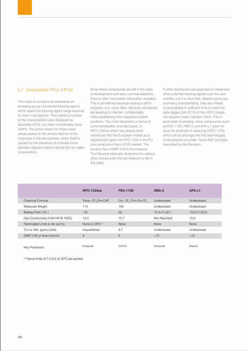
46
5.7 Unsaturated HFCs (HFOs)
This class of compounds represents an emerging group of potential blowing agents which spans the blowing agent range required for foam manufacture. They exhibit a number of the characteristics also displayed by saturated HFCs, but have considerably lower GWPs. The prime reason for these lower values relates to the shorter lifetime of the molecules in the atmosphere, which itself is caused by the presence of a double bond between adjacent carbon atoms (the so-called unsaturation).
Since these compounds are still in the state of development and early commercialisation, there is often incomplete information available. This is sometimes because testing is still in progress, but, more often, because companies are seeking to maintain confidentiality while establishing their respective patent positions. The most advanced, in terms of commercialisation and disclosure, is HFO-1234ze which has already been introduced into the European market as a replacement option for HFC-134a in the PU one-component foam (OCF) market. The product has a GWP of 6 in this instance. The following table also illustrates the various other compounds that are believed to fall in this class.
Further disclosures are expected on these and other potential blowing agents over the next months, but it is clear that, despite some very promising characteristics, they are unlikely to be available in sufficient time to meet the early stages (pre-2015) of the HCFC phase-out required under Decision XIX/6. This is particularly frustrating, since compounds such as FEA-1100, HBA-2 and AFA-L1 seem to have the potential of replacing HCFC-141b, which will be amongst the first technologies to be phased-out under ‘worst-first’ principle mandated by the Decision.
HFO-1234ze FEA-1100 HBA-2 AFA-L1
Chemical Formula Trans- CF3CH=CHF Cis- CF3-CH=CH-CF3 Undisclosed Undisclosed
Molecular Weight 114 164 Undisclosed Undisclosed
Boiling Point ( 0C ) -19 32 15.3<T<32.1 10.0<T<30.0
Gas Conductivity (mW/mK @ 100C) 13.0 10.7 Not Reported 15.9
Flammable Limits in Air (vol.%) None to 280C^ None None None
TLV or OEL (ppm) (USA) Unpublished 9.7 Undisclosed Undisclosed
GWP (100 yr time horizon) 6 5 <15 <15
Key Producers
^ Flame limits of 7.0-9.5 at 300C are quoted
Honeywell DuPont Honeywell Arkema

47
UNEP DTIE Foam Sourcebook - 2010

48
Section 6.Decision-making process
“When developing country experience is limited, a balanced assessment of available information is critical”
49
UNEP DTIE Foam Sourcebook - 2010
6.1 Establishing Technical Feasibility and Economic ViabilityThe technical feasibility of a blowing agent technology will depend on a number of factors which will include:
• The chemistry of the foam formulation being processed
• The existing (or future) foam processing equipment being proposed
• The quantity of foam being manufactured and sold each year
• The application of the foam and the local standards pertaining
• Experience already gained by others both internationally and locally in similar processes and applications
Chemistry of the foam formulation being processedFoam formulations are selected and optimised for a variety of differing purposes. For rigid foams, these can include such aspects as reaction to fire, mechanical strength and resilience. For flexible foams these might be matters such as softness and elastic response. Inevitably, the relationship between these properties and density of foam required to deliver them, becomes a key aspect of the assessment, making the inter-linkage between technical and economic components of the decision-making process almost unavoidable from the outset. The formulation itself could also require additional components to accommodate certain blowing agent solutions (e.g. flame retardants) and these can affect the overall economic viability of a potential solution.
Existing (or future) foam processing equipment being proposedEvery project will have its constraints with respect to equipment. These may be imposed through the existing equipment at hand, particularly if no capital is available to support the proposed technology transition. Alternatively, where capital is availa ble, it is likely that the budget will be capped. This may be on an absolute basis or on a level of investment per unit quantity of foam manufactured or blowing agent used. Either way, there may be the potential necessity to make compromises in order to accommodate the equipment that can be made available.
Quantity of foam being manufactured or sold each yearWhere capital investments need to be made, the cost-effectiveness of the investment will depend on the quantity of foam being produced on the equipment currently and will also need to take into account any future trends that are expected. Although the most cost-effective investment is not always the best, it is likely that a threshold will exist (in US$ per unit of production) above which, the investment is viewed as non-viable. Conversely, the same assessment might be made by establishing the minimum amount of foam that would need to be manufactured annually to support the investment.
Application of the foam and the local standards pertainingThere is no value in producing foam in the most cost-effective manner if it is not fit-for-purpose in its intended application. In some instances, this may not be established immediately but could emerge only with time. In order to combat this risk, attempts are often made to mimic the long-term requirements on the foam in an accelerated fashion (e.g. ageing at elevated temperatures). This approach serves to provide a view of the likely future performance of the foam. However, since the predictive capabilities of such techniques always have their limitations, the tendency is naturally to be a little more conservative in the deployment of new technologies. In some instances, local standards will also introduce a level of conservatism in order to ensure fitness-for-purpose. Enterprises need to satisfy themselves that risk is mitigated to the extent possible, but that the final approach is not so over-cautious as to rule out perfectly acceptable alternatives. This is usually an issue of expert judgement and will involve a number of local factors as well as generic technology issues.
Section 6. Decision-making process

50
Experience already gained by others both internationally and locally in similar processes and applications One of the primary factors in providing confidence about technology selection emerges is knowledge that a technology has been deployed successfully elsewhere – particularly if the circumstances are similar to those pertaining to the proposed technology transition. Accordingly, an enterprise needs to be alert to the information available to it from a number of sources. This can include any of the following:
• International Foam Conferences
• Assessments contained in the UNEP Foams Technical Options Committee Reports
• Advice and information from National Ozone Units
• Local trade associations
• Periodic regional workshops convened by one or more Implementing Agencies
• Supplier Literature (particularly where this contains case studies)
• Supplier Literature (particularly where this contains case studies)
These sources take on increased importance when technology transitions are contemplated, particularly if the pace of technology development is rapid. In this context, there is no doubt that the implementation of Decision XIX/6 has brought about challenges that were previously unforeseen. As technology suppliers respond to these challenges, the level of offerings in the market place increases – often specifically tailored to the needs of developing country enterprises and markets. In these circumstances, good market intelligence is a critical part of the decision-making process.
6.2 Evaluating Safety Aspects and Environmental ImpactThere are a number of examples where the some excellent technological options have been ruled out or, at least demoted, because of their safety aspects and/or environmental impacts. For a long period, HCFC-123 was seen as a very promising replacement for CFC-11 as a foam blowing agent (low ODP and GWP) but was eventually ruled out because of its intrinsic toxicity to man.
Evaluating safety is a complex issue and involves the assessment of risk, as defined by the intrinsic hazard of a chemical and the statistical likelihood of exposure. Even hazardous chemicals can be handled safely where the solution can be engineered to avoid exposure. An example would be the regular handling of petroleum on a fuel station forecourt. However, for foam, the fact that many blowing agents remain in the foam after manufacture and slowly diffuse during the use phase, means that having intrinsically hazardous substances as blowing agents is usually not tolerable. For this reason, it is only in exceptional circumstances that such an option would be contemplated. Toxicity testing, in particular, is therefore a high priority for potential blowing agents and enterprises would be cautioned against choosing a technology where the toxicity of the blowing agent has not already been fully characterised.
Section 3 of this Sourcebook has already addressed the evaluation of environmental impact of technology transitions as it relates to the climate criterion. As noted there, three separate parameters can contribute to the overall impact. These are:
• Embodied (or embedded) energy
• Direct emissions of greenhouse gases (particularly of those used as blowing agents)
• Indirect emissions of CO2 related to the energy consumption of buildings or products (where the energy saved by a foam can reduce those emissions)
However, apart from climate impacts, there can be a number of other environmental considerations. These include:
• Impact on low level ozone formation (usually associated with VOCs)
• Environmental (or human) toxicity of atmospheric breakdown products
Decision XIX/6 is careful in its language to ensure that the evaluation process includes this wider perspective when it encourages Parties to the Montreal Protocol to:
‘…….promote) the selection of alternatives to HCFCs that minimise environmental impacts, in particular impacts on the climate, as well as meeting other health, safety and economic considerations’.
However, seldom does one technology minimise all health, safety and environmental impacts at the same time and there is therefore a value judgement to be made between them. For HCFC alternatives, some criteria are absolute (e.g. zero ODP), while others are graduated factors, such as embodied energy and(GWP. When selecting a technology it is therefore important to identify the non-negotiable elements and use them for screening purposes before evaluating these graduated factors. This process is shown schematically in Section 6.4.

51
UNEP DTIE Foam Sourcebook - 2010
6.3 Assessing Cost Effectiveness and PracticalityCost effectiveness is another graduated factor and can be assessed either in the context of:
I. Initial capital costs
II. On-going variable costs
III. A combination of the two
The appropriate choice for comparison often depends on the size of the operation being managed by the enterprise. Where the plant throughputs are potentially high, a greater degree of capital investment can be justified, since the investment per unit of production is still relatively low and may be recovered by operational savings. However, where plant throughputs are likely to be low, capital investment might need to be minimised with possible incremental cost being incurred at the operational level. Of course, the best option under any method of evaluation is one that involves minimal capital cost and results in operational savings. In practice, the basis of comparison is a choice for the individual investor. However, the key aspect to bear in mind is that competing technologies need to be assessed using the same approach.
Care needs to be taken to ensure that cost comparisons take into account all factors. For example, a blowing agent may be more expensive per kilogram purchased, but may result in a foam that can deliver the required properties at lower density. Such a blowing agent may therefore be more cost effective than a less expensive alternative, which does not have the same capability. The improved cost-effectiveness arises through the fact that less of the overall chemical formulation is needed.
If cost effectiveness is a graduated factor, then some aspects of practicality are absolute in their nature. For example, a key parameter in making technology selections is the local availability of the alternative blowing agent. Although it may generally be viewed that an alternative blowing agent is available ‘globally’, it is always worth checking the local distribution network. Long shipment distances can affect costs but, more importantly, can jeopardise production continuity if supplies are subsequently interrupted through lack of local stocks.
Not only is availability an issue, but packaging can also be a factor. This may be dictated by the physical characteristics of the blowing agent (e.g. boiling point) and also local legislation. In some instances, local legislation may limit the amount of the blowing agent that can be stored in one place.
6.4 Summary Decision TreeIn summary, there are a number of absolute and relative factors that combine to influence technology selection. In some instances, the process of selection can be iterative. However, the following Decision Tree is an attempt to provide some guidance on the logical prioritisation of issues to be considered if the maximisation of climate benefit is to be achieved while seeking to be compliant with the ozone objectives of Decision XIX/6.
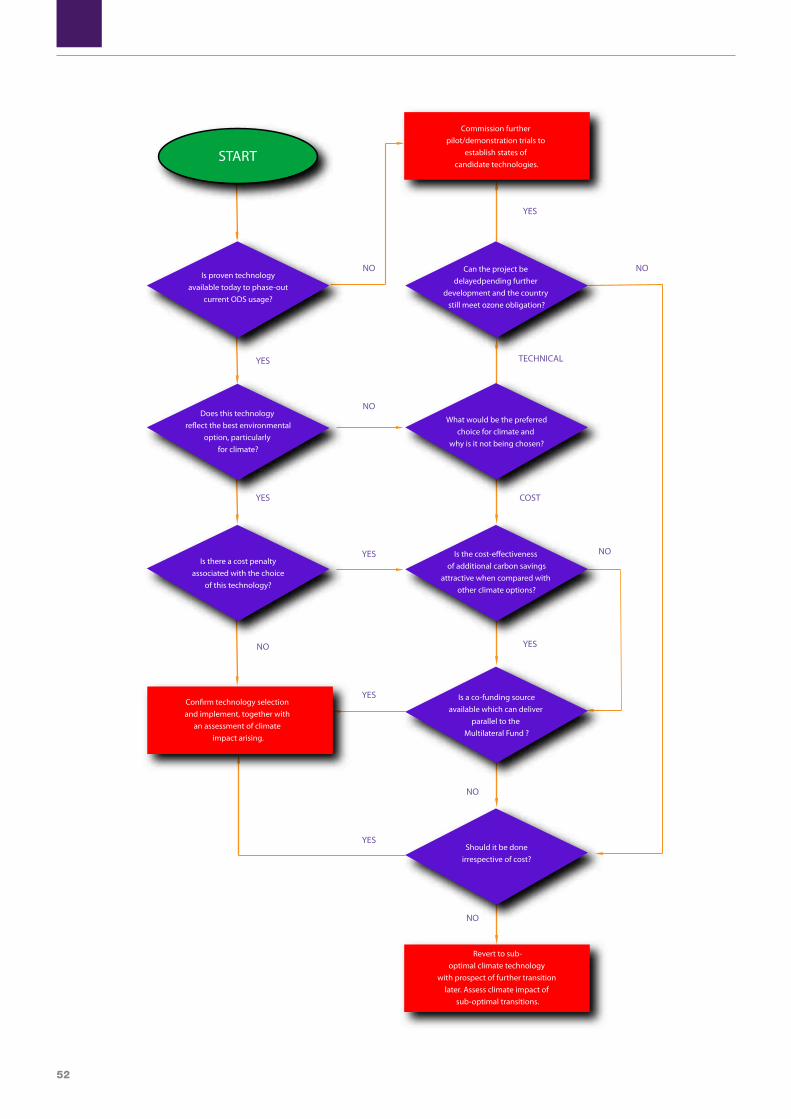
52
NO
NO
NO
NO
YES
YES
YES
YES
NO
NO NO
NO
YES
YES
NO
TECHNICAL
YES
COST
YES
YES
Is proven technologyavailable today to phase-out
current ODS usage?
Does this technology re�ect the best environmental
option, particularly for climate?
Is there a cost penaltyassociated with the choice
of this technology?
Con�rm technology selection and implement, together with
an assessment of climate impact arising.
Is a co-funding sourceavailable which can deliver
parallel to the Multilateral Fund ?
Should it be doneirrespective of cost?
Revert to sub-optimal climate technology
with prospect of further transition later. Assess climate impact of
sub-optimal transitions.
Commission further pilot/demonstration trials to
establish states of candidate technologies.
Can the project be delayedpending further
development and the country still meet ozone obligation?
What would be the preferredchoice for climate and
why is it not being chosen?
Is the cost-e�ectiveness of additional carbon savings
attractive when compared with other climate options?
START

53
UNEP DTIE Foam Sourcebook - 2010

54
Section 7.Review of specific factors influencing the selection of alternative technologies at application level
“Demands on blowing agents vary substantially by process and application, so specific information is essential”
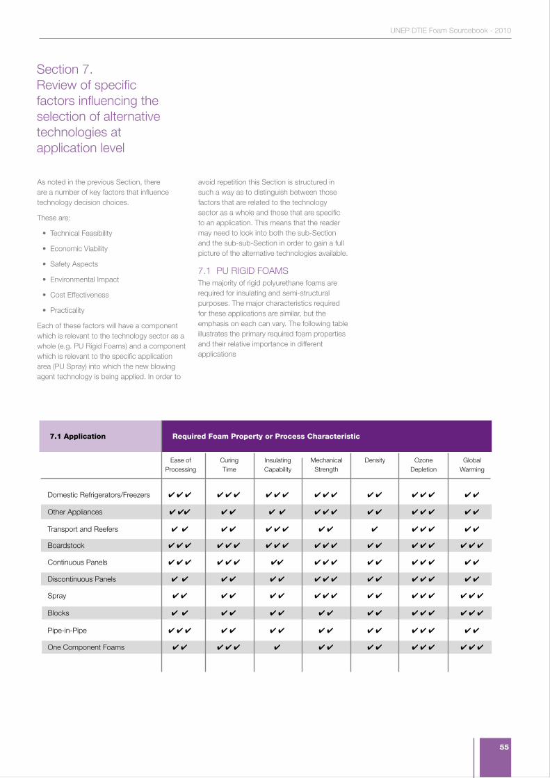
55
UNEP DTIE Foam Sourcebook - 2010
As noted in the previous Section, there are a number of key factors that influence technology decision choices.
These are:
• Technical Feasibility
• Economic Viability
• Safety Aspects
• Environmental Impact
• Cost Effectiveness
• Practicality
Each of these factors will have a component which is relevant to the technology sector as a whole (e.g. PU Rigid Foams) and a component which is relevant to the specific application area (PU Spray) into which the new blowing agent technology is being applied. In order to
avoid repetition this Section is structured in such a way as to distinguish between those factors that are related to the technology sector as a whole and those that are specific to an application. This means that the reader may need to look into both the sub-Section and the sub-sub-Section in order to gain a full picture of the alternative technologies available.
7.1 PU RIGID FOAMSThe majority of rigid polyurethane foams are required for insulating and semi-structural purposes. The major characteristics required for these applications are similar, but the emphasis on each can vary. The following table illustrates the primary required foam properties and their relative importance in different applications
4 4 4 4 4 4 4 4 4 4 4 4 4 4 4 4 4 4 4
4 44 4 4 4 4 4 4 4 4 4 4 4 4 4 4
4 4 4 4 4 4 4 4 4 4 4 4 4 4 4
4 4 4 4 4 4 4 4 4 4 4 4 4 4 4 4 4 4 4 4
4 4 4 4 4 4 44 4 4 4 4 4 4 4 4 4 4
4 4 4 4 4 4 4 4 4 4 4 4 4 4 4 4
4 4 4 4 4 4 4 4 4 4 4 4 4 4 4 4 4
4 4 4 4 4 4 4 4 4 4 4 4 4 4 4 4
4 4 4 4 4 4 4 4 4 4 4 4 4 4 4 4
4 4 4 4 4 4 4 4 4 4 4 4 4 4 4 4
Ease of Processing
Curing Time
Insulating Capability
Mechanical Strength
Density Ozone Depletion
Global Warming
Required Foam Property or Process Characteristic7.1 Application
Domestic Refrigerators/Freezers
Other Appliances
Transport and Reefers
Boardstock
Continuous Panels
Discontinuous Panels
Spray
Blocks
Pipe-in-Pipe
One Component Foams
Section 7. Review of specific factors influencing the selection of alternative technologies at application level

56
Critical Foam Processing and Product PropertiesEach of the required foam properties and processing characteristics are addressed in turn below:
1. Ease of processing can be measured in a variety of ways relating to both handling of chemicals (polyol and isocyanate components) and the action of those chemicals once combined. In practice, often the most significant factor is the capability of the polyurethane system when fully mixed to flow easily. This is particularly important for injection processes, such as the filling of cabinets, but is also very relevant when producing boardstock and other laminate products, since thickness tolerances and density distribution can all be affected by flow characteristics. In the case of cabinet filling, the combination of a well flowing formulation and a well-designed cavity should enable the optimum foam densities to be achieved. This is an important element for cost, strength and weight, as described under sub-bullet 5.
2. Curing Time. During foaming, expansion takes place through the vaporization of the blowing agent and (in most formulations) the generation of the carbon dioxide from the water-isocyanate reaction. This expansion process - accompanied by the progress of the polymerization and the exotherm of the reactions - results in the generation of an increasing internal pressure. This process exerts force upon the constraining surfaces, which can be either the walls of the cabinet/mould or the faces of a press (either static or conveyor). The curing time is the time at which the constraint can be removed without further expansion of the foam beyond pre-determined specifications. Since the curing dictates the minimum residence time in either a mould or laminating press, it is directly linked to productivity, either through the number of injections that can be achieved per hour or the line speed that can be maintained while achieving adequate cure. Of course, slow curing time can be overcome by increasing the number of moulds/jigs in use or by increasing the length of a continuous laminator, but these are major capital items and are not addressed lightly.
3. Insulating Performance. Where polyurethane foams are used for insulation purposes, they contribute directly to the overall energy consumption of the object into which they are placed. This can range from a domestic refrigerator or water heater, right through to a building. The energy consumption is greatly influenced by the insulating performance of the foam, but other variables such as compressor efficiency (in the case of refrigerators) and boiler efficiency in the case of buildings can be equally significant. In addition, heat gains and losses through air movement are critical contributors to overall energy performance. Therefore, door gaskets on refrigerators, draught excluders in buildings and the behaviour patterns adopted by users are all critical factors. The thermal conductivity of the foam, measured on a sample cut from a cross section of the foam, is a good indication of the foam insulating performance and is relatively easy to measure. However, this also needs to be monitored over time to identify any trends arising from blowing agent losses from the cells. Typical thermal conductivity values range from 0.018 W/mK to 0.04 W/mK when measured at normal ambient temperatures. For a refrigerator, as a rule of thumb and maintaining the other parameters constant, when the foam thermal conductivity is increased by a given percentage, the energy consumption of the refrigerator increases in value by half of that percentage.
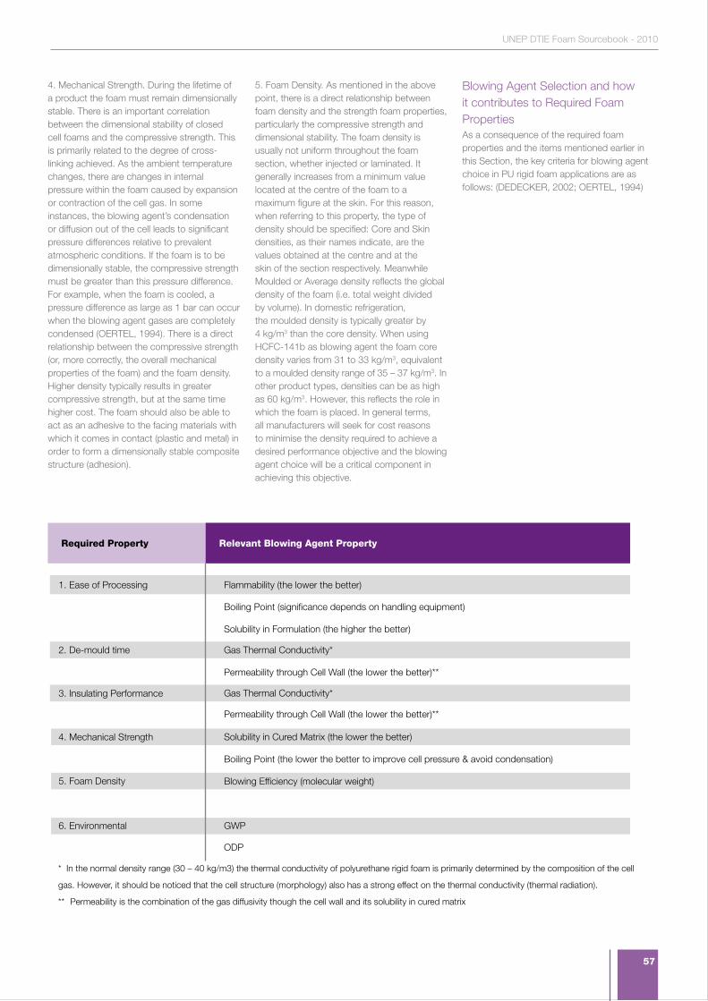
57
UNEP DTIE Foam Sourcebook - 2010
4. Mechanical Strength. During the lifetime of a product the foam must remain dimensionally stable. There is an important correlation between the dimensional stability of closed cell foams and the compressive strength. This is primarily related to the degree of cross-linking achieved. As the ambient temperature changes, there are changes in internal pressure within the foam caused by expansion or contraction of the cell gas. In some instances, the blowing agent’s condensation or diffusion out of the cell leads to significant pressure differences relative to prevalent atmospheric conditions. If the foam is to be dimensionally stable, the compressive strength must be greater than this pressure difference. For example, when the foam is cooled, a pressure difference as large as 1 bar can occur when the blowing agent gases are completely condensed (OERTEL, 1994). There is a direct relationship between the compressive strength (or, more correctly, the overall mechanical properties of the foam) and the foam density. Higher density typically results in greater compressive strength, but at the same time higher cost. The foam should also be able to act as an adhesive to the facing materials with which it comes in contact (plastic and metal) in order to form a dimensionally stable composite structure (adhesion).
5. Foam Density. As mentioned in the above point, there is a direct relationship between foam density and the strength foam properties, particularly the compressive strength and dimensional stability. The foam density is usually not uniform throughout the foam section, whether injected or laminated. It generally increases from a minimum value located at the centre of the foam to a maximum figure at the skin. For this reason, when referring to this property, the type of density should be specified: Core and Skin densities, as their names indicate, are the values obtained at the centre and at the skin of the section respectively. Meanwhile Moulded or Average density reflects the global density of the foam (i.e. total weight divided by volume). In domestic refrigeration, the moulded density is typically greater by 4 kg/m3 than the core density. When using HCFC-141b as blowing agent the foam core density varies from 31 to 33 kg/m3, equivalent to a moulded density range of 35 – 37 kg/m3. In other product types, densities can be as high as 60 kg/m3. However, this reflects the role in which the foam is placed. In general terms, all manufacturers will seek for cost reasons to minimise the density required to achieve a desired performance objective and the blowing agent choice will be a critical component in achieving this objective.
Blowing Agent Selection and how it contributes to Required Foam PropertiesAs a consequence of the required foam properties and the items mentioned earlier in this Section, the key criteria for blowing agent choice in PU rigid foam applications are as follows: (DEDECKER, 2002; OERTEL, 1994)
Flammability (the lower the better)
Boiling Point (significance depends on handling equipment)
Solubility in Formulation (the higher the better)
Gas Thermal Conductivity*
Permeability through Cell Wall (the lower the better)**
Gas Thermal Conductivity*
Permeability through Cell Wall (the lower the better)**
Solubility in Cured Matrix (the lower the better)
Boiling Point (the lower the better to improve cell pressure & avoid condensation)
Blowing Efficiency (molecular weight)
GWP
ODP
Relevant Blowing Agent Property Required Property
1. Ease of Processing
2. De-mould time
3. Insulating Performance
4. Mechanical Strength
5. Foam Density
6. Environmental
* In the normal density range (30 – 40 kg/m3) the thermal conductivity of polyurethane rigid foam is primarily determined by the composition of the cell
gas. However, it should be noticed that the cell structure (morphology) also has a strong effect on the thermal conductivity (thermal radiation).
** Permeability is the combination of the gas diffusivity though the cell wall and its solubility in cured matrix
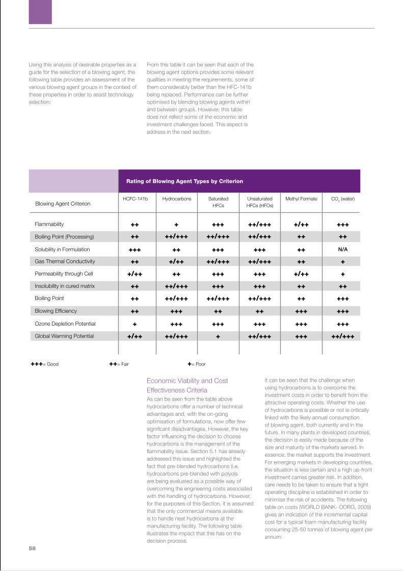
58
Using this analysis of desirable properties as a guide for the selection of a blowing agent, the following table provides an assessment of the various blowing agent groups in the context of these properties in order to assist technology selection:
From this table it can be seen that each of the blowing agent options provides some relevant qualities in meeting the requirements, some of them considerably better than the HFC-141b being replaced. Performance can be further optimised by blending blowing agents within and between groups. However, this table does not reflect some of the economic and investment challenges faced. This aspect is address in the next section.
Economic Viability and Cost Effectiveness CriteriaAs can be seen from the table above hydrocarbons offer a number of technical advantages and, with the on-going optimisation of formulations, now offer few significant disadvantages. However, the key factor influencing the decision to choose hydrocarbons is the management of the flammability issue. Section 5.1 has already addressed this issue and highlighted the fact that pre-blended hydrocarbons (i.e. hydrocarbons pre-blended with polyols are being evaluated as a possible way of overcoming the engineering costs associated with the handling of hydrocarbons. However, for the purposes of this Section, it is assumed that the only commercial means available is to handle neat hydrocarbons at the manufacturing facility. The following table illustrates the impact that this has on the decision process.
It can be seen that the challenge when using hydrocarbons is to overcome the investment costs in order to benefit from the attractive operating costs. Whether the use of hydrocarbons is possible or not is critically linked with the likely annual consumption of blowing agent, both currently and in the future. In many plants in developed countries, the decision is easily made because of the size and maturity of the markets served. In essence, the market supports the investment. For emerging markets in developing countries, the situation is less certain and a high up-front investment carries greater risk. In addition, care needs to be taken to ensure that a tight operating discipline is established in order to minimise the risk of accidents. The following table on costs (WORLD BANK- OORG, 2009) gives an indication of the incremental capital cost for a typical foam manufacturing facility consuming 25-50 tonnes of blowing agent per annum:
++ + +++ ++/+++ +/++ +++
++ ++/+++ ++/+++ ++/+++ ++ ++
+++ ++ +++ +++ ++ N/A
++ +/++ ++/+++ ++/+++ ++ +
+/++ ++ +++ +++ +/++ +
++ ++/+++ +++ +++ ++ ++
++ ++/+++ ++/+++ ++/+++ ++ +++
++ +++ ++ ++ +++ +++
+ +++ +++ +++ +++ +++
+/++ ++/+++ + ++/+++ +++ ++/+++
HCFC-141b Hydrocarbons SaturatedHFCs
Unsaturated HFCs (HFOs)
Methyl Formate CO2 (water)
Rating of Blowing Agent Types by Criterion
Flammability
Blowing Agent Criterion
Boiling Point (Processing)
Solubility in Formulation
Gas Thermal Conductivity
Permeability through Cell
Insolubility in cured matrix
Boiling Point
Blowing Efficiency
Ozone Depletion Potential
Global Warming Potential
+++= Good ++= Fair += Poor
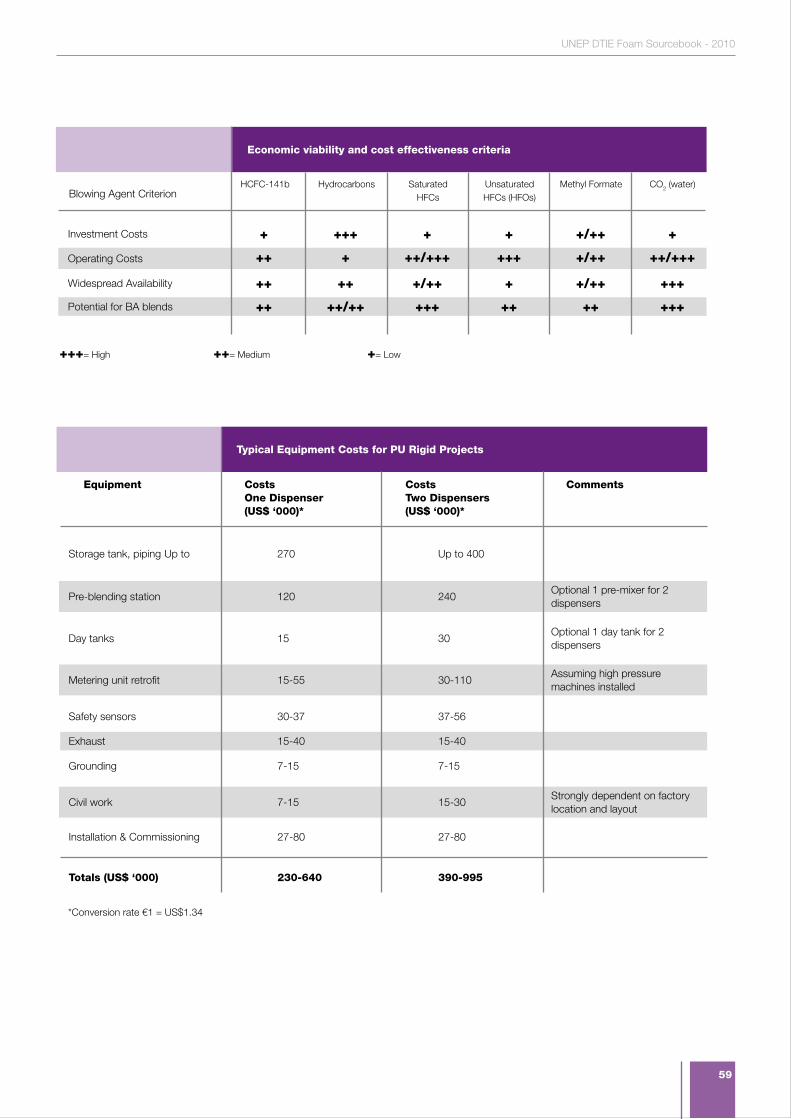
59
UNEP DTIE Foam Sourcebook - 2010
+ +++ + + +/++ +
++ + ++/+++ +++ +/++ ++/+++
++ ++ +/++ + +/++ +++
++ ++/++ +++ ++ ++ +++
HCFC-141b Hydrocarbons SaturatedHFCs
Unsaturated HFCs (HFOs)
Methyl Formate CO2 (water)
Economic viability and cost effectiveness criteria
Investment Costs
Blowing Agent Criterion
Operating Costs
Widespread Availability
Potential for BA blends
+++= High ++= Medium += Low
Typical Equipment Costs for PU Rigid Projects
Equipment Costs One Dispenser(US$ ‘000)*
Costs Two Dispensers(US$ ‘000)*
Comments
Storage tank, piping Up to 270 Up to 400
Pre-blending station 120 240 Optional 1 pre-mixer for 2 dispensers
Day tanks 15 30 Optional 1 day tank for 2 dispensers
Metering unit retrofit 15-55 30-110 Assuming high pressure machines installed
Safety sensors 30-37 37-56
Exhaust 15-40 15-40
Grounding 7-15 7-15
Civil work 7-15 15-30 Strongly dependent on factory location and layout
Installation & Commissioning 27-80 27-80
Totals (US$ ‘000) 230-640 390-995
*Conversion rate €1 = US$1.34
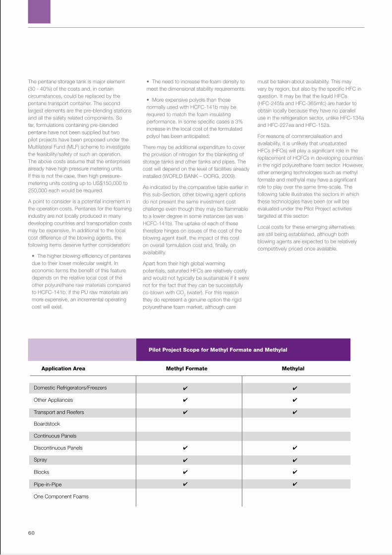
60
The pentane storage tank is major element (30 - 40%) of the costs and, in certain circumstances, could be replaced by the pentane transport container. The second largest elements are the pre-blending stations and all the safety related components. So far, formulations containing pre-blended pentane have not been supplied but two pilot projects have been proposed under the Multilateral Fund (MLF) scheme to investigate the feasibility/safety of such an operation. The above costs assume that the enterprises already have high pressure metering units. If this is not the case, then high pressure-metering units costing up to US$150,000 to 250,000 each would be required.
A point to consider is a potential increment in the operation costs. Pentanes for the foaming industry are not locally produced in many developing countries and transportation costs may be expensive. In additional to the local cost difference of the blowing agents, the following items deserve further consideration:
• The higher blowing efficiency of pentanes due to their lower molecular weight. In economic terms the benefit of this feature depends on the relative local cost of the other polyurethane raw materials compared to HCFC-141b. If the PU raw materials are more expensive, an incremental operating cost will exist.
• The need to increase the foam density to meet the dimensional stability requirements.
• More expensive polyols than those normally used with HCFC-141b may be required to match the foam insulating performance. In some specific cases a 3% increase in the local cost of the formulated polyol has been anticipated.
There may be additional expenditure to cover the provision of nitrogen for the blanketing of storage tanks and other tanks and pipes. The cost will depend on the level of facilities already installed (WORLD BANK – OORG, 2009).
As indicated by the comparative table earlier in this sub-Section, other blowing agent options do not present the same investment cost challenge even though they may be flammable to a lower degree in some instances (as was HCFC-141b). The uptake of each of these therefore hinges on issues of the cost of the blowing agent itself, the impact of this cost on overall formulation cost and, finally, on availability.
Apart from their high global warming potentials, saturated HFCs are relatively costly and would not typically be sustainable if it were not for the fact that they can be successfully co-blown with CO2 (water). For this reason they do represent a genuine option the rigid polyurethane foam market, although care
must be taken about availability. This may vary by region, but also by the specific HFC in question. It may be that the liquid HFCs (HFC-245fa and HFC-365mfc) are harder to obtain locally because they have no parallel use in the refrigeration sector, unlike HFC-134a and HFC-227ea and HFC-152a.
For reasons of commercialisation and availability, it is unlikely that unsaturated HFCs (HFOs) will play a significant role in the replacement of HCFCs in developing countries in the rigid polyurethane foam sector. However, other emerging technologies such as methyl formate and methylal may have a significant role to play over the same time-scale. The following table illustrates the sectors in which these technologies have been (or will be) evaluated under the Pilot Project activities targeted at this sector:
Local costs for these emerging alternatives are still being established, although both blowing agents are expected to be relatively competitively priced once available.
Pilot Project Scope for Methyl Formate and Methylal
Application Area Methyl Formate Methylal
Domestic Refrigerators/Freezers
Other Appliances
Transport and Reefers
Boardstock
Continuous Panels
Discontinuous Panels
Spray
Blocks
Pipe-in-Pipe
One Component Foams
4 4
4 4
4 4
4 4
4 4
4 4
4 4
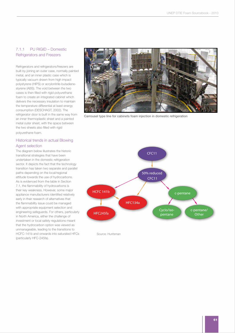
61
UNEP DTIE Foam Sourcebook - 2010
7.1.1 PU RIGID – Domestic Refrigerators and Freezers
Refrigerators and refrigerators/freezers are built by joining an outer case, normally painted metal, and an inner plastic case which is typically vacuum drawn from high impact polystyrene (HIPS) or acrylonitrile-butadiene-styrene (ABS). The void between the two cases is then filled with rigid polyurethane foam to create an integrated cabinet which delivers the necessary insulation to maintain the temperature differential at least energy consumption (DESCHAGT, 2002). The refrigerator door is built in the same way from an inner thermoplastic sheet and a painted metal outer sheet, with the space between the two sheets also filled with rigid
polyurethane foam.
Historical trends in actual Blowing Agent selectionThe diagram below illustrates the historic transitional strategies that have been undertaken in the domestic refrigeration sector. It depicts the fact that the technology transition has taken two separate and parallel paths depending on the local/regional attitude towards the use of hydrocarbons. As is evidenced from the table in Section 7.1, the flammability of hydrocarbons is their key weakness. However, some major appliance manufacturers identified relatively early in their research of alternatives that the flammability issue could be managed with appropriate equipment selection and engineering safeguards. For others, particularly in North America, either the challenge of investment or local safety regulations meant that the hydrocarbon option was viewed as unmanageable, leading to the transitions to HCFC-141b and onwards into saturated HFCs (particularly HFC-245fa).
50% reduced CFC11
HCFC 141b
HFC245fa
c-pentane
Cyclo/iso-pentane
c-pentane/Other
HFC134a
CFC11
Source: Huntsman
Carrousel type line for cabinets foam injection in domestic refrigeration
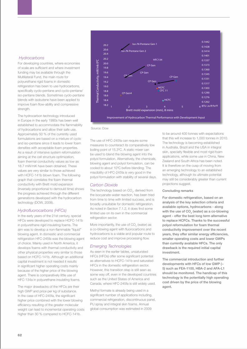
62
HydrocarbonsFor developing countries, where economies of scale are sufficient and where investment funding may be available through the Multilateral Fund, the main route for polyurethane rigid foams in domestic refrigeration has been to use hydrocarbons, specifically cyclo-pentane and cyclo-pentane/ iso-pentane blends. Sometimes cyclo-pentane blends with isobutene have been applied to improve foam flow-ability and compressive strength.
The hydrocarbon technology introduced in Europe in the early 1990s has been well established to accommodate the flammability of hydrocarbons and allow their safe use. Approximately 50 % of the currently used formulations are based on a mixture of cyclo and iso-pentane since it leads to lower foam densities with acceptable foam properties. As a result of intensive system reformulation aiming at the cell structure optimization, foam thermal conductivity values as low as 18.7 mW/mK have been obtained. These values are very similar to those achieved with HCFC-141b blown foam. The following graph that correlates the foam thermal conductivity with Brett mold expansion (inversely proportional to demould time) shows the progress achieved through the different generations developed with the hydrocarbon technology (DOW, 2008).
Hydrofluorocarbons (HFCs)In the early years of the 21st century, special HFCs were developed to replace HCFC-141b in polyurethane rigid insulating foams. The aim was to develop a non-flammable “liquid” blowing agent. In domestic and commercial refrigeration HFC-245fa was the blowing agent of choice. Mainly used in North America, it develops foams with thermal conductivity and other physical properties very similar to those based on HCFC-141b. Although an additional capital investment is not needed it results in significant higher operating costs mainly because of the higher price of the blowing agent. There is comparatively little use of HFC-134a in polyurethane insulating foams.
The major drawbacks of the HFCs are their high GWP and price per kg of substance. In the case of HFC-245fa, the significant higher price combined with the lower blowing efficiency resulting of the greater molecular weight can lead to incremental operating costs higher than 30 % compared to HCFC-141b.
The use of HFC-245fa can require some measures to counteract its comparatively low boiling point of 15.30C. A static mixer can be used to blend the blowing agent into the polyol formulation. Alternatively, the chemicals, blowing agent and polyol formulation, can be cooled to about 100C before blending. The miscibility of HFC-245fa is very good in the polyol formulation with stability of several days.
Carbon DioxideThe technology based on CO2, derived from the isocyanate-water reaction, has been tried from time to time with limited success, and is broadly unsuitable for domestic refrigeration. As noted in Section 7.1.2, it does find some limited use on its own in the commercial refrigeration sector.
More importantly, the use of CO2 (water) as a co-blowing agent with fluorocarbons and hydrocarbons is a viable and popular route to reduce cost and improve processing flow.
Emerging TechnologiesAs seen in the earlier tables, unsaturated HFCs (HFOs) offer some significant potential as alternatives to HCFC-141b and saturated HFCs in the domestic refrigeration sector. However, this transition step is still seen as some way off, even in the developed countries such as the United States of America and Canada, where HFC-245fa is still widely used.
Methyl formate is already being used in a significant number of applications including, commercial refrigeration, discontinuous panel, PU spray and integral skin foams. Annual global consumption was estimated in 2009
to be around 400 tonnes with expectations that this will increase to 1,000 tonnes in 2010. The technology is becoming established in Australia, Brazil and the USA in integral skin, specialty flexible and most rigid foam applications, while some use in China, New Zealand and South Africa has been noted. It is therefore on the cusp of moving from an emerging technology to an established technology, although its ultimate potential may still be considerably greater than current projections suggest.
Concluding remarks
For domestic refrigeration, based on an analysis of the key selection criteria and available options, hydrocarbons - along with the use of CO2 (water) as a co-blowing agent - offer the best long term alternative to replace HCFCs. Thanks to the successful polyol reformulation for foam thermal conductivity improvement over the recent years, they offer similar energy efficiencies, smaller operating costs and lower GWPs than currently available HFCs. The only drawback is the required initial capital investment.
The commercial introduction and further developments with HFCs of low GWP (~ 5) such as FEA-1100, HBA-2 and AFA-L1 should be monitored. The handicap of this technology is the potentially high operating cost driven by the price of the blowing agent.
0.1442
0.1428
0.1414
0.1401
0.1337
0.1373
0.1360
0.1345
0.1331
0.1317
0.1303
0.1290
0.1276
0.126218.2
18.4
18.6
18.8
19.0
19.2
19.4
19.6
19.8
20.0
20.2
20.4
20.6
20.2
654321 BTU .in/ft2hr0F
Brett mold expansion (mm), 8 mins
Improvement of Hydrocarbon Thermal Performance with Development Input
Ther
mal
Con
duct
ivity
, mW
/mk
00 C
Iso-/N-Pentane Gen 1
Iso-/N-Pentane Gen 2
HFC134
CP Gen
CP GenCP Gen CP Gen
CP Gen4
CP Gen
HCFC
HCFC
CFC 11
Source: Dow
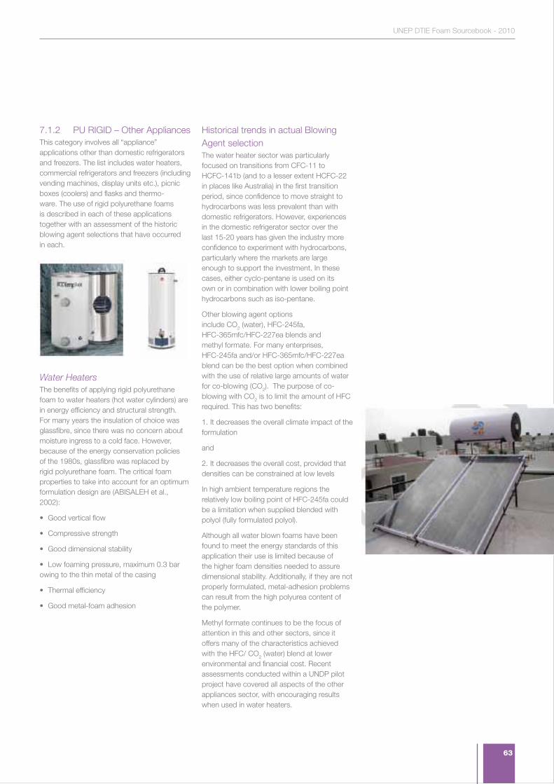
63
UNEP DTIE Foam Sourcebook - 2010
7.1.2 PU RIGID – Other AppliancesThis category involves all “appliance” applications other than domestic refrigerators and freezers. The list includes water heaters, commercial refrigerators and freezers (including vending machines, display units etc.), picnic boxes (coolers) and flasks and thermo-ware. The use of rigid polyurethane foams is described in each of these applications together with an assessment of the historic blowing agent selections that have occurred in each.
Water HeatersThe benefits of applying rigid polyurethane foam to water heaters (hot water cylinders) are in energy efficiency and structural strength. For many years the insulation of choice was glassfibre, since there was no concern about moisture ingress to a cold face. However, because of the energy conservation policies of the 1980s, glassfibre was replaced by rigid polyurethane foam. The critical foam properties to take into account for an optimum formulation design are (ABISALEH et al., 2002):
• Good vertical flow
• Compressive strength
• Good dimensional stability
• Low foaming pressure, maximum 0.3 bar owing to the thin metal of the casing
• Thermal efficiency
• Good metal-foam adhesion
Historical trends in actual Blowing Agent selectionThe water heater sector was particularly focused on transitions from CFC-11 to HCFC-141b (and to a lesser extent HCFC-22 in places like Australia) in the first transition period, since confidence to move straight to hydrocarbons was less prevalent than with domestic refrigerators. However, experiences in the domestic refrigerator sector over the last 15-20 years has given the industry more confidence to experiment with hydrocarbons, particularly where the markets are large enough to support the investment. In these cases, either cyclo-pentane is used on its own or in combination with lower boiling point hydrocarbons such as iso-pentane.
Other blowing agent options include CO2 (water), HFC-245fa, HFC-365mfc/HFC-227ea blends and methyl formate. For many enterprises, HFC-245fa and/or HFC-365mfc/HFC-227ea blend can be the best option when combined with the use of relative large amounts of water for co-blowing (CO2). The purpose of co-blowing with CO2 is to limit the amount of HFC required. This has two benefits:
1. It decreases the overall climate impact of the formulation
and
2. It decreases the overall cost, provided that densities can be constrained at low levels
In high ambient temperature regions the relatively low boiling point of HFC-245fa could be a limitation when supplied blended with polyol (fully formulated polyol).
Although all water blown foams have been found to meet the energy standards of this application their use is limited because of the higher foam densities needed to assure dimensional stability. Additionally, if they are not properly formulated, metal-adhesion problems can result from the high polyurea content of the polymer.
Methyl formate continues to be the focus of attention in this and other sectors, since it offers many of the characteristics achieved with the HFC/ CO2 (water) blend at lower environmental and financial cost. Recent assessments conducted within a UNDP pilot project have covered all aspects of the other appliances sector, with encouraging results when used in water heaters.
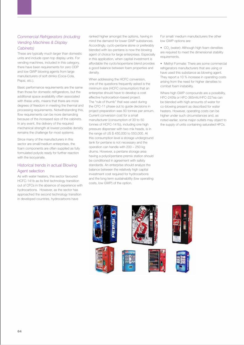
64
Commercial Refrigerators (including Vending Machines & Display Cabinets)These are typically much larger than domestic units and include open top display units. For vending machines, included in this category, there have been requirements for zero ODP and low GWP blowing agents from large manufacturers of soft drinks (Coca-Cola, Pepsi, etc.).
Basic performance requirements are the same than those for domestic refrigerators, but the additional space availability often associated with these units, means that there are more degrees of freedom in meeting the thermal and processing requirements. Notwithstanding this, flow requirements can be more demanding because of the increased size of the cabinets. In any event, the delivery of the required mechanical strength at lowest possible density remains the challenge for most systems.
Since many of the manufacturers in this sector are small/medium enterprises, the foam components are often supplied as fully formulated polyols ready for further reaction with the isocyanate.
Historical trends in actual Blowing Agent selectionAs with water heaters, this sector favoured HCFC-141b as its first technology transition out of CFCs in the absence of experience with hydrocarbons. However, as the sector has approached the second technology transition in developed countries, hydrocarbons have
ranked higher amongst the options, having in mind the demand for lower GWP substances. Accordingly, cyclo-pentane alone or preferably blended with iso-pentane is now the blowing agent of choice for large enterprises. Especially in this application, when capital investment is affordable the cyclo/isopentane blend provides a good balance between foam properties and density.
When addressing the HCFC conversion, one of the questions frequently asked is the minimum size (HCFC consumption) that an enterprise should have to develop a cost effective hydrocarbon-based project. The “rule of thumb” that was used during the CFC-11 phase out to guide decisions in project preparation was 50 tonnes per annum. Current conversion cost for a small manufacturer (consumption of 30 to 50 tonnes of HCFC-141b), including one high pressure dispenser with two mix heads, is in the range of US $ 450,000 to 550,000. At this consumption level a storage underground tank for pentane is not necessary and the operation can handle with 200 – 250 kg drums. However, a pentane storage area having a polyol/pentane premix station should be conditioned in agreement with safety standards. An enterprise should analyze the balance between the relatively high capital investment cost required for hydrocarbons and the long term sustainability (low operating costs, low GWP) of the option.
For small/ medium manufacturers the other low GWP options are:
• CO2 (water): Although high foam densities are required to meet the dimensional stability requirements.
• Methyl Formate: There are some commercial refrigerators manufacturers that are using or have used this substance as blowing agent. They report a 10 % increase in operating costs arising from the need for higher densities to combat foam instability.
Where high GWP compounds are a possibility, HFC-245fa or HFC-365mfc/HFC-227ea can be blended with high amounts of water for co-blowing present as described for water heaters. However, operating costs can be higher under such circumstances and, as noted earlier, some major outlets may object to the supply of units containing saturated HFCs.
65
UNEP DTIE Foam Sourcebook - 2010
Picnic Boxes (Coolers), Flasks and Thermoware As in the case of water heaters, the benefits of using rigid polyurethane foam are in a premium insulation value and the increased strength-to-weight ratio achievable with intermediate density foams. In general, technology requirements are not as demanding in these sectors as in other forms of appliance, although resilience is a key component for a long product life.
Historical trends in actual Blowing Agent selectionIn view of their size and relatively low-tech image, these products have not received the attention from the chemicals suppliers to which other sectors have been treated. It was therefore natural, in the first instance that they defaulted to the easiest of first-stage transitions – i.e. primarily to HCFC-141b.
As the sector now looks to move out of HCFC use, the options are the same as for the other product groups discussed in Section 7.2. Depending on the operation size, hydrocarbons, CO2 (water), methyl formate and HFC-245fa and HFC-365mfc/HFC-227ea may be the choice, with blends of two or more blowing agents being favoured to optimise formulation performance in some cases.
Concluding remarks
When compared with the stringent requirements of the domestic refrigeration sector, the demands on polyurethane systems are less severe for ‘other appliances’. However, the range of products and equipment manufactured mean that the overall chemistry needs to be both robust and versatile.
Hydrocarbons (particularly cyclo/iso-pentane blends) are undoubtedly the blowing agents of choice where the critical mass is sufficient to justify the investment. Most other technologies are, to some degree, compromises, the choice of which will depend on the ranking of the foam performance criteria.
7.1.3 PU RIGID – Transport and ReefersThis sector of foam use covers two distinct groups of insulated container. The first is typically a road trailer which can be either a tank or of straight-sided construction. The second is a demountable insulated heavy steel box. These containers are often called ‘reefers’ and are fundamentally designed for shipping, although with the capability to be transported inter-modally on roads and railways. The international nature of their use means that they may often circum-navigate the world several times during their lifetime, thereby making it important that the structural integrity of the unit is retained while in use and the materials of construction are identifiable at end-of-life. It is estimated that the number of reefers currently in circulation globally is in the order of 1,000,000, carried on over 10,000 container ships.
These applications, more than any other, place particular emphasis on the durability of the foam used in the construction. In addition, there is the clear commercial challenge of maximising the storage capacity, while minimising the overall spatial footprint of the container. In many instances, the outside dimensions of both road-based and intermodal transport are legally defined so that consistency can be assured. This puts a particular strain on the requirements of the foam in order to achieve the minimum wall thickness whilst maintaining the level of insulation required to avoid the contents of containers being spoiled (FTOC, 2006).
The challenge for manufacturers of both types of insulated container is the need either inject or laminate foam systems in such a way as to create durable structures capable of withstanding the rigours of transportation.
Typical foam densities in these applications are in the order of 40 to 45 kg/m3. Historically, CFCs were used to create the foams, often in-situ. The bulk of manufacturing has now switched to HCFC-141b in order to retain the thermal insulation characteristics. However, where HCFCs have already been phased out, the main choice has been between saturated HFCs co-blown with CO2 (water) to the extent permissible without sacrificing thermal properties, and hydrocarbons. With the vast majority of reefer manufacture now concentrated in China, the significance of the technology choice when replacing HCFC-141b is self evident.
Flammability is not a product performance issue in this instance, but may still present challenges in processing. However, as with most other automated processes, it should be possible to engineer solutions to manage the risk. In this context, hydrocarbons are seen to represent probably the best option, particularly in the light of recent formulation improvements which have delivered better thermal performance. N-pentane is understood to represent the most favoured option at the moment, since its boiling point provides better processing than other options.
The potential for methyl formate may also emerge further in future, but the technology will need to demonstrate advantages. With dimensional stability being a critical aspect of this application, the solubility of methyl formate in the matrix may demand higher densities.
Even more unproven, but still of potential interest are the unsaturated HFCs, since they may be able to deliver significant thermal upsides. However, this assumes that additional energy performance will be relevant. In practice, the benefit will not be in lower retained temperatures but in the ability to maintain the desired temperature for longer. This is an extremely important factor on board container ships where multiple containers have their refrigeration units connected to the ship’s power supplies.

66
Historical trends in actual Blowing Agent selection
ReefersAs noted earlier, the insulated containers known as ‘reefers’ are primarily designed for intermodal use, with a particular emphasis on shipping. These units were typically insulated with CFC-blown foam and converted naturally to HCFC-141b across the world when CFC restrictions came into place. With product lifetimes in the order of 10-15 years typically, most of the CFC-containing units are likely to be out-of-service in the next few years, but require active management at end of life if the blowing agents are not to be released. The opportunity for recovery is significant because the steel structures retain the blowing agent throughout the service life of the containers.
HCFC-141b is still the blowing agent of choice for most reefer manufacture because the bulk of the global production has moved now to China, thereby avoiding the need for developed country producers make a further technology transition. The previous sub-section outlined the options available for the Chinese producers and it is likely that there will be considerable focus on making hydrocarbons work.
Truck Bodies For truck bodies, saturated HFCs, co-blown with CO2 (water), have been used as HCFC-141b replacements in developed countries. HFC-365mfc/227ea blends generally provide better flow characteristics than HFC-245fa, which tends to froth foam and create additional back pressure. Where safe use can be assured, hydrocarbons are also having an increasing role, based on the improved formulations mentioned earlier.
It seems likely that there will be some interest in unsaturated-HFCs (HFOs) in this sector in future, if they are seen to offer better thermal performance or other operational advantages.
Tanks Tanks present a specific processing challenge because of their shape. Therefore foam formulations need to be particularly versatile to process successfully in these circumstances. CFCs and HCFCs have been able to provide the level of versatility required, but other options are less well proven. Hydrocarbons may be less favoured in these less well-controlled environments and this may leave an opening for methyl formate, with its reported lower flammability. However, capability in processing will need to be confirmed. The HFCs (both saturated and unsaturated) remain the other options and saturated HFCs may provide the solution in developed countries for the foreseeable future until unsaturated-HFC technologies mature.
Concluding remarks
The use of insulation foam in transport applications provides a performance enhancement which is critical to the cold chain in general and the food chain in particular. There are a number of variants in terms of transport design and modality, therefore generalisations across the sector are difficult to make. However, hydrocarbons are likely to play a significant role in meeting the HCFC phase-out requirement – particularly where levels of automation can be achieved.

67
UNEP DTIE Foam Sourcebook - 2010
7.1.4 PU RIGID – BoardstockContinuous processes for rigid polyurethane foams have been mostly limited to developed countries, where the size and maturity of the markets has supported the investment. In North America, a high proportion of the demand for PU Boardstock (often referred to in the United States as “polyiso”) comes from the residential sheathing market, where the product competes with extruded polystyrene and mineral wool. In Europe, the use is focused much more on the commercial and industrial buildings sector, although recent increases in energy standards in the residential sector have improved its competitive position with respect to mineral wool.
In developing countries, continuous laminators are rare with only Turkey and Mexico known to have significant investments. However, this situation is expected to change rapidly as attention is focused globally on the need for greater energy efficiency in buildings in order to combat climate change. The growth in construction has already stimulated rapid growth of the extruded polystyrene market in China and the development of a significant polyurethane boardstock industry in China is expected to follow close behind.
Historical trends in actual Blowing Agent selectionAs with most other sectors based on rigid polyurethane foam, the blowing agent of choice for the period up to the early 1990s was CFC-11. Under pressure to make the transition from CFCs, most of the industry initially went to HCFC-141b, with the exception of a few manufacturers in the European Union. German manufacturers, in particular, were encouraged by pending regulatory pressures to move directly to hydrocarbons and managed to make the transition directly.
The cost-effectiveness of the hydrocarbon solution spurred others to investigate it, and where the product’s fire classification was not impaired, further transitions took place.
However, the primary shift to hydrocarbons came in the 2003-2004 period when the North American “polyiso” industry, facing a ban on the further use of HCFC-141b in 2005, decided to move to hydrocarbons rather than to saturated HFCs, which were its other choice.
Only very few developed country manufacturers have made the transition to saturated HFCs and this has been primarily where product fire requirements have necessitated this transition and the cost burden can be absorbed.
The few developing country activities are either using HCFC-141b or HCFC-22 currently. Retrofit to hydrocarbons would require significant further investment and it may be easier for new capacity to be installed based on hydrocarbon from the outset in view of the likely growth in demand for this product type in coming years.
Concluding remarks
The PU Boardstock industry is heavily focused in developed countries at present, but substantial growth is expected to occur in developing countries as the focus increases on the insulation of buildings globally. The growth of construction in places such as China means that increased levels of insulation are essential. In this context, there will be few, if any, PU laminators meeting the cut-off date for transitional investment under Decision XIX/6, but it will be important for new investments to be guided to the most environmentally sound technologies, in view of their future significance.

68
7.1.5 PU RIGID – Continuous PanelsThe continuous PU panel market has grown substantially in Europe over the last 20-30 years as demand for pre-fabricated distribution ‘sheds’ has increased. Continuous panels provide a particularly effective way of achieving highly engineered structures with low air leakage rates. Although the recent economic downturn has slowed the rate of growth significantly, the products continue to take market share from more conventional forms on construction.
The technology has been successfully transferred into the North American and Australasian markets and is expected to move into Asia. In Japan, steel-faced panels already have a market based but this is more focused on the residential sector where the products are used for sidings. It is clear that volumes need to be sufficient to support continuous processes and it is quite common to see initial market development occur with discontinuously produced panels or with panels traded from other regions. This shipment is possible because of the relatively high added value of the products.
Historical trends in actual Blowing Agent selectionThe major growth in the steel-faced panel sector has primarily occurred since the phase-out of CFCs, although examples of earlier CFC-containing panels are likely to emerge in the waste stream over the next 15-20 years. These were typically much thinner than today’s products (30-40mm then vs. 80-100mm today). The initial technology transition in Europe was to HCFC-141b although, as with PU Boardstock, national regulatory pressures, and economies of scale led to an increasing focus on the use of hydrocarbons.
One exception to this for a number of years was the UK market where stringent fire codes, underwritten by the insurance companies, prevented the use of hydrocarbons for such applications. In the face of the need to transfer from HCFCs by the end of 2004, a number of manufacturers switched to saturated HFCs (typically HFC-365mfc), but have gradually switched towards hydrocarbons as further formulations have been developed and optimised.
There is little current exploitation of PU continuous panel technology in developing countries to date and that which exists is understood to be still using HCFC-141b, with minor use of hydrocarbons and HCFC-22.
Concluding remarks
As with PU Boardstock, this sector does not represent a significant challenge under the auspices of Decision XIX/6, since few technology transitions will be required. However, there is a need to ensure that any new capacity established in Article 5 countries takes due account of the environmental impacts associated with such investments.

69
UNEP DTIE Foam Sourcebook - 2010
7.1.6 PU RIGID – Discontinuous PanelsIn contrast to the continuous processes, discontinuous panel manufacture is more endemic in developing countries and, as in the developed countries, it is concentrated within small and medium sized enterprises (SMEs). The markets served are also rather different, with many of the panels being used for internal cold storage purposes rather than as external cladding.
PU discontinuous panel is more likely to compete against steel-faced panels produced with expanded or extruded polystyrene cores, where fire codes allow these products to be used. The market can therefore be highly cost sensitive and it is often difficult to support significant investments.
Many discontinuous panel manufacturers also serve the refrigerated transport sector and, as noted in Section 7.1.3, this sector requires products made to precise tolerances and, often tailored to specific circumstances. This allows the panel manufacturer to recover more of the value-added in its product pricing in order to offset the more competitive construction market.
Historical trends in actual Blowing Agent selection
In similar fashion to other discontinuous processes, manufacturers of discontinuous polyurethane panels have been consistently concerned about the health and safety impacts of technology transitions in their factories. CFCs and, in particular, CFC-11 was an ideal blowing agent under these circumstances because of its inert nature and versatile processing characteristics.
At the point at which the first transitions out of CFCs had to made, it was clear that HCFCs were the only option that could be accommodated with existing equipment. Hence the transition to HCFC-141b was virtually universal, with the exception of some manufacturers who had processes that depended on froth foaming. In these instances, blends involving HCFC-22 were also used. In at least one instance, HFC-134a was used for the same purpose.
Subsequent transitions out of HCFCs have primarily been towards saturated HFCs, with both HFC-245fa and HFC-365mfc/227ea being adopted in a number of applications. As foaming equipment has been replaced across
the industry, efforts have been made to install equipment that can handle hydrocarbons. Accordingly, there has been some shift towards the use of hydrocarbons in sector over recent years.
Both methyl formate and unsaturated HFCs are seen as potential future blowing agents. The manufacture of discontinuous panels using methyl formate has been included in the recent Brazil/Mexico Pilot Project conducted by UNDP and initial results look encouraging.
Concluding remarks
This sector has a significant population of enterprises engaged in it throughout the Article 5 countries. It is therefore likely to be a significant focus within HCFC Phase-out Management Plans under Decision XIX/6. There is a growing degree of confidence that solutions avoiding the selection of saturated HFCs can be made based on emerging technologies.

70
7.1.7 PU RIGID – SpraySprayed rigid PU foams are closed-celled, air tight, resistant to mildew and fungal attack, provide no food value to rodents and have good vapour barrier properties (Randall & Lee, 2002). They find utility as an in situ applied insulation in applications where irregular shapes or the need for a monolithic layer of foam exists. These applications include building envelope, pipe insulation, tank insulation, rail cars, residential roofing and floors (Gum, 1992). Sprayed foam is now finding increasing applications in retrofitting/refurbishing roofs, walls, floors and windows of existing buildings as well as in new constructions such us commercial offices, industrial factories and warehouses, agricultural pig and chicken farms (Randall & Lee, 2002). In the 2008 Progress Report the Foams Technical Options Committee states: “PU Spray Foam is being increasingly recognized as an efficient means of retrofitting a number of building types”. The use of spray rigid foam has significantly increased both in developed and developing countries since it combines the PU insulation properties with ease of application and the unique adhesive ability to provide in-situ insulation on a variety of surfaces.
In general, the use of PU spray foam is most prevalent on flat roofs and also between the studs of walls in timber frame buildings. These applications require differing densities of foams based on the fact that roofs generally have to carry some foot traffic, or at least need to be able to support crawling boards. Typically, the roofs also require a UV protection coat, as shown in the diagram. The spray foam product to fill the cavities between studs, however, is much lighter in density (typically 20-25 kg/m3) and its primary purpose is to deliver thermal insulation and gap filling. The latter is very helpful in avoiding air leakage which, in turn, can improve the overall energy performance of a building substantially. Typically, such low density foams do not hold their thermal performance irrespective of the blowing agent used. This means that these applications are less sensitive to blowing agent choice, at least from a thermal conductivity perspective.
The chemical components are mixed and sprayed directly onto the substrate using fixed ratio (normally 1:1 in volume) positive displacement pump portable machines, equipped with spray guns. A high ~30 kg/min output machine is using for roofing whilst a small ~10 kg/min output equipment is more suitable for stud wall insulation.

71
UNEP DTIE Foam Sourcebook - 2010
Generally polyurethane technology is used, but for some specific fire or temperature requirements polyisocyanurate (PIR) is applied. Good adhesion between the substrate and the sprayed foam is extremely important so all substrates should be clean, dry and free of grease, oil, loose material or dust. The foam needs to be highly reactive, especially for adhering to vertical surfaces. Typical core densities are in the range of 35 to 40 kg/m3 for roofs. Additional foam requirements are: high resilience, low moisture absorption and transmission; good thermal properties; sufficient fire performance to meet relevant building codes; application capability in a variety of climatic conditions; and ease of use (FTOC, 2006).
The use of PU Spray Foam is at its most prevalent in North America, Spain and Japan. All three regions have therefore already faced the challenge of HCFC-141b phase-out. Early experiments with hydrocarbon technologies in the United States resulted in incidents which confirmed that the flammability of hydrocarbons was unmanageable in this application. Attempts to overcome this set-back with changes in practice have failed to deliver and interest in the use of hydrocarbons has waned.
In Japan, super-critical CO2 technology has been introduced and made some headway, although levels of market penetration, whilst significant, suggest that there maybe limitations in some applications. Nonetheless, the technology has now become the focus of a possible UNDP pilot-project which might shed more light on the potential.
As noted earlier, CO2 (water) provides an option for less critical applications, but the system must be well formulated to prevent shrinkage and to promote good adhesion.
Apart from the saturated HFCs which are now well established, there is initial evidence to suggest that unsaturated-HFCs could have a
significant role to play in the future of PU Spray Foam worldwide. A recent study (BOGDAN, 2009) that covered the diversity of the polyol blends found in the industry indicated that spray foams blown with unsaturated HFCs of low GWP were equivalent or better quality compared to current HFC-245fa based foams and that they can be processed in existing commercial equipment.
There is also the possibility that methyl formate could have a role to play, but it is not yet clear whether the flammability of methyl formate will be sufficiently low to meet the safety requirements of the application. Although PU Spray was included in the recent UNDP pilot project on methyl formate, results are still awaited on the foams produced. In addition, it is not yet clear how the processing boundaries were evaluated.
For super-critical CO2, the technology relies on direct CO2 injection to the polyol component. With a minor modification to conventional spray machines (Gusmer FF type with a 1:1 mixing ratio by volume) supercritical CO2 assisted water blown foams with good dimensional stability and a comparable density to HCFC-141b blown systems are produced. Liquid CO2 cooled to 0 °C with a heat exchanger is supplied to the Gusmer type auxiliary pump which is remodelled so that brine can circulate internally and the CO2 injected to the polyol component. The unitary cost to modify conventional Gusmer type equipment is estimated to be US $ 14,000. Foams with either normal rigid polyurethane (PUR) or polyisocyanurate (PIR) for applications requiring flame-retardant systems can be provided. Despite its significant penetration in the Japan spray foam market it is still not clear how widely applicable this technology may be outside of the country.
Historical trends in actual Blowing Agent selectionOriginally, the technology used throughout the world was based on CFC-11. At the point where CFC-11 was phased-out, HCFC-141b became the obvious replacement and few others were evaluated. Only at the point of HCFC-141b phase-out, were hydrocarbons and saturated HFCs seriously evaluated. In the United States, there was also some intermediate evaluation of HCFC-22 in view of the fact that the phase-out date for HCFC-22 was later and the most appropriate saturated HFCs (notably HFC-245fa) were only just becoming available.
A proportion of the PU Spray Foam market in all three territories (North America, Spain and Japan) moved to CO2 (water) blown foam, but this was not seen to be a universal solution. The choice of saturated HFC depended to an extent on availability, which itself was driven by the patent cover in each region. This led to only HFC-245fa being used in North America while, in Europe, both HFC-245fa and HFC-365mfc/227ea have been used successfully. In Japan, where pressure to avoid saturated HFCs has been greater, the balance of the market has been shared between HFC-245fa and super-critical CO2.
The rapid growth of the PU Spray market in China over recent years based on HCFC-141b has created an urgent need to evaluate the best alternatives for this region – particularly because of the ‘worst-first’ presumption in Decision XIX/6.
Concluding remarks
This is another sector where the prevailing technology in use in developed countries is unlikely to provide a full solution for Article 5 country transitions. The emerging technologies include super-critical CO2, methyl formate and unsaturated HFCs, but it is still unclear which of these will best meet developing country needs.

72
7.1.8 PU RIGID – BlocksPU rigid foam blocks (called ‘buns’ in the United States) can be produced by either continuous or discontinuous processes. The purpose of producing foams in this form is to create the largest level of utility from a single manufacturing source. This makes PU Block manufacture particularly popular in small and emerging markets. Blocks can be cut into slabs in order to allow the production of composite panels with metal or plasterboard surfaces. They can also be cut into foamed pipe sections using computer-controlled specialist cutting equipment. This type of approach becomes even more powerful for the fabrication of three dimensional shaped for the insulation of tanks and vessels.
However, the penalty paid for the versatility offered by block foam technologies is in the utilisation of the foam itself. Even for well designed computer-controlled cutting equipment it is difficult to get above 55% yields for foam utilisation. This leads to considerable waste streams and a requirement for appropriate waste management strategies – particularly if the blowing agent selection involves gases that are either ozone depleting or contribute significantly to climate change. The situation is slightly less severe for continuous processes than for discontinuous processes, but the waste issue remains a significant one for all fabricated parts.
Historical trends in actual Blowing Agent selectionThe often small-scale nature of PU Block Foam plants has meant that polyurethane systems have needed to be both versatile and tolerant. Most, if not all, PU Block Foam facilities therefore used CFC-11 until, at least, the early 1990s when HCFC-141b began to emerge as a virtual drop-in replacement. For
the manufacture of blocks, the rise/cure profile is critical and this relates directly back to the boiling point of the blowing agent. If the cure is too slow it leads to block collapse, but if the curing on-set is too early it leads to highly distorted cell structures.
Hydrocarbons (particularly n-pentane) also meet these requirements but the concern has always been the management of accumulation of pockets of blowing agent within the manufacturing facilities. Flame proofing and adequate ventilation are both required to avoid these risks and the level of investment is typically too great for this type of process – particularly in the case of discontinuous production.
Transitions from HCFCs in developed countries have tended to follow the saturated HFC option, with HFC-365mfc/227ea blends being used in Europe (primarily because of their boiling points) and HFC-245fa tending to be used in North America, where experience with froth foaming technology is more advanced than elsewhere.
Concluding remarks
This type of process has particular use in Low Volume Consuming (LVC) countries because of its relatively low investment cost and its versatility in meeting a number of foam end-uses. The most likely solution for the HCFC-141b phase-out could be pre-blended hydrocarbons (avoiding the need to mix on site) or methyl formate. However, in both cases, the flammability risks need to be fully characterised in order to define the minimum investments required (if any) for adequate risk management.

73
UNEP DTIE Foam Sourcebook - 2010
7.1.9 PU RIGID – Pipe-in-PipeThe deployment of this technology has grown rapidly in the last 25 years based on the increased trends towards district heating systems. These systems were already well established in former Eastern Bloc countries, but have been promoted further by recognition that small-scale, localised combined heat and power (CHP) facilities are an important component of future decentralised energy generation strategies to combat climate change.
The technology involves the in-situ foaming of polyurethane insulation foam between a steel pipe and outer casing which may be high density polyethylene pipe or other similar product. There are a number of continuous and discontinuous processing methods including casting, injecting with a withdrawing mixing head (see first illustration) and forming the external jacket in a continuous process (see second illustration).
The drawbacks of this method include the difficulty in manufacturing long pipe sections and ensuring that the quality of the foam is consistent throughout. Similar issues exist for a variant of this process called the paper draw-through method.
For continuous processes the method is as shown below:
In this instance the key to the success of the process is in ensuring that the external pipe covering provides an integral seal. This is important since many such pipes are installed underground and need to be particularly immune to water ingress.
Additional challenges for continuous processes include the fact that changes in pipework and insulation diameters can involve long set-up times. There is also a need for sophisticated process control.
Historical trends in actual Blowing Agent selectionAs with many other complex processes, the technology was simplified by the original adoption of the most versatile of blowing agents, CFC-11. In transitioning from CFC-11, a significant part of the industry went to HCFC-141b in order to optimise thermal performance. However, a number of European manufacturers also focused on the further development of hydrocarbon systems based on n-pentane and/or cyclo-pentane. These have since been optimised and are now perceived as broadly state-of-the-art. Other users of HCFCs in developed countries have transitioned to saturated HFCs, such as HCFC-245fa and HFC-365mfc/227ea.
Concluding remarks
The future technology options for pipe-in-pipe polyurethane foams in developing countries seem to be based on the capability to achieve appropriate transfer of hydrocarbon technologies. There are very few intrinsic drawbacks with the hydrocarbon choice since the manufacturing processes are relatively sophisticated and engineering solutions can be managed. For the products themselves, they are largely underground and represent little intrinsic hazard. In addition, there is little penalty in insulation thicknesses with the most recent, optimised hydrocarbon technologies.

74
7.1.10 PU RIGID – One Component FoamsThese are different from a number of other foam types, since the technology relies on the moisture-curing (from atmospheric sources) of low density polyurethane foam that has been froth foamed. The primary use of such products is for gap filling in buildings to prevent excessive air movements. The thermal insulating properties of these products are broadly secondary.
The technology has widespread use in Europe both in support of products for new build and also for renovation. The foam is delivered in aerosol cans which can be relatively small for direct consumer sales, but may be larger canisters for trade uses.
Historical trends in actual Blowing Agent selectionSince the blowing agent also acts as a propellant, they need to be gaseous in nature. CFC-12 was the blowing agent of choice in the early phases of market development. Although there were some moves towards HCFC-22, in the first transition, a number of key manufacturers elected to move directly to solutions based around HFC-134a. In some instances, this included co-blends with di-methyl ether and other hydrocarbons.
The emissive nature of the application caught the attention of the EU regulators on fluorinated gases as early as the late 1990s and led to a focus on the potential to phase-out the use of HFCs from the sector. There was considerable discussion about the potential for all-hydrocarbon solutions, but
this met with resistance from a number of manufacturers based in countries where either process or product standards prevented the use of hydrocarbons in isolation.
In the F-Gas Regulation that finally emerged, pressure was placed on the substitution of HFC-134a for blowing agents with lower global warming potentials (e.g. HFC-152a and, more latterly, unsaturated HFCs) by the imposition of a future ban, albeit with potential exceptions on safety grounds. The use of di-methyl ether has therefore grown on the back of this technology driver, but many manufacturers have also seen the potential for HFO-1234ze, which has been commercialised by Honeywell in time to meet the F-Gas phase-out schedules for HFC-134a. Honeywell have reported significant market development in this sector as a consequence.
Concluding remarks
From the developing country perspective, the opportunity exists to move relatively swiftly from the use of HCFC-22, where used, provided that access to appropriate technology can be negotiated. This technology step should jump over the use of saturated HFCs and may lead to the adoption of hydrocarbon technologies based on di-methyl ether, possibly in combination with unsaturated HFCs.
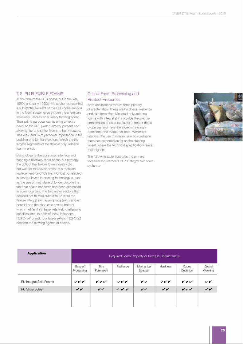
75
UNEP DTIE Foam Sourcebook - 2010
4 4 4 4 4 4 4 4 4 4 4 4 4 4 4 4 4 4 4
4 4 4 4 4 4 4 4 4 4 4 4 4 4 4 4
Ease of Processing
Skin Formation
Resilience Mechanical Strength
Hardness Ozone Depletion
Global Warming
Application
PU Integral Skin Foams
PU Shoe Soles
7.2 PU FLEXIBLE FOAMSAt the time of the CFC phase-out in the late 1980s and early 1990s, this sector represented a substantial element of the ODS consumption in the foam sector, even though the chemicals were only used as an auxiliary blowing agent. Their prime purpose was to bring an extra boost to the CO2 (water) already present and allow lighter and softer foams to be produced. This was (and is) of particular importance in the bedding and furniture sectors, which are the largest segments of the flexible polyurethane foam market.
Being close to the consumer interface and needing a relatively rapid phase-out strategy, the bulk of the flexible foam industry did not wait for the development of a technical replacement for CFCs (i.e. HCFCs) but elected instead to invest in existing technologies, such as the use of methylene chloride, despite the fact that health concerns had been expressed in some quarters. The two major sectors that decided not to take such a route were the flexible integral skin applications (e.g. car dash boards) and the shoe sole sector, both of which had (and still have) relatively challenging specifications. In both of these instances, HCFC-141b and, to a lesser extent, HCFC-22 became the blowing agents of choice.
Critical Foam Processing and Product PropertiesBoth applications require three primary characteristics. These are hardness, resilience and skin formation. Moulded polyurethane foams with integral skins provide the precise combination of characteristics to deliver these properties and have therefore increasingly dominated the market for both. Within car interiors, the use of integral skin polyurethane foam has extended as far as the steering wheel, where the technical specifications are at their highest.
The following table illustrates the primary technical requirements of PU integral skin foam systems:
Required Foam Property or Process Characteristic

76
In general, the specifications for automotive applications are more stringent than for other applications in view of the safety implications associated with these uses. This is reflected in the requirements shown in the table.
1. Ease of processing. Virtually all of the products manufactured in this sector are moulded. The processing characteristics that are most significant therefore relate to the flow of the polyurethane system through the mould, and its consistency of rise and cure. A further property of importance is mould-release. All of these parameters are fundamentally a combination of the polyurethane system, the mould design and mould operation. It is therefore difficult to point to a universal foam formulation that delivers optimum properties in all integral skin foam applications.
2. Skin Formation. This is an absolutely critical characteristic both from the point of view of aesthetics and longevity of service. Imperfections in the surface finish can lead to further accidental damage, since the integrity of the surface can be breached more easily. As is shown later in this sub-Section, the choice of blowing agent can have a substantial influence on the quality of skin formation.
3. Resilience. In softer foams, the characteristic would be known as visco-elasticity. It is fundamentally, the ability to regain its original shape following impact. In most integral skin applications, where densities are higher, the process is virtually instantaneous and the foam is described as resilient. This property is dependent on
a balance between polyurethane system formulation and foam density. These can be varied to a degree, but automotive manufacturers understandably seek the required resilience at minimum density in order to save weight in their vehicles.
4. Mechanical Strength. Again, mechanical strength in the foams is broadly a function of density. It is important that the foams are able to provide sufficient structural integrity to meet their requirements. For automotive fascias, for example, the foam can be used to encompass glove compartments and other such features. It is therefore important that factors such as tear strength, elongation, tensile strength and compression are all sufficient to meet the application requirements.
5. Hardness. This is a characteristic that is measured across many plastics and rubbers and is effectively assessing the resistance to indentation. There are a number of routine test regimes, amongst which Shore and Rockwell are the most well known. The avoidance of skin penetration is critical for both automotive and shoe sole applications in order that the products concerned can have a level of longevity.
Although significantly inter-related, these properties collectively represent an expression of what needs to be achieved by a successful polyurethane foam system. The impact that blowing agent selection can have on these characteristics is the subject of the next sub-Section.
Blowing Agent Selection and how it contributes to Required Foam PropertiesThe following table provides an overview of the interaction of blowing agent selection with desired foam properties:
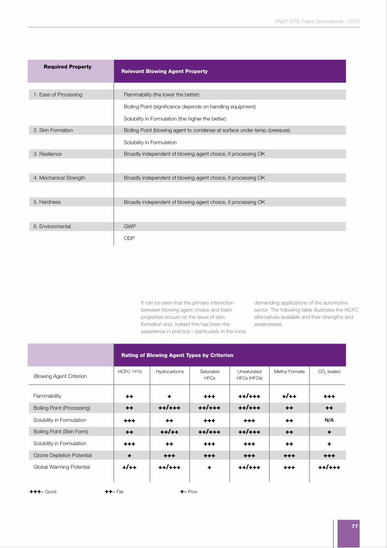
77
UNEP DTIE Foam Sourcebook - 2010
Flammability (the lower the better)
Boiling Point (significance depends on handling equipment)
Solubility in Formulation (the higher the better)
Boiling Point (blowing agent to condense at surface under temp./pressure)
Solubility in Formulation
Broadly independent of blowing agent choice, if processing OK
Broadly independent of blowing agent choice, if processing OK
Broadly independent of blowing agent choice, if processing OK
GWP
ODP
Relevant Blowing Agent Property Required Property
1. Ease of Processing
2. Skin Formation
3. Resilience
4. Mechanical Strength
5. Hardness
6. Environmental
It can be seen that the primary interaction between blowing agent choice and foam properties occurs on the issue of skin formation and, indeed this has been the experience in practice – particularly in the more
demanding applications of the automotive sector. The following table illustrates the HCFC alternatives available and their strengths and weaknesses.
++ + +++ ++/+++ +/++ +++
++ ++/+++ ++/+++ ++/+++ ++ ++
+++ ++ +++ +++ ++ N/A
++ ++/++ ++/+++ ++/+++ ++ +
+++ ++ +++ +++ ++ +
+ +++ +++ +++ +++ +++
+/++ ++/+++ + ++/+++ +++ ++/+++
HCFC-141b Hydrocarbons SaturatedHFCs
Unsaturated HFCs (HFOs)
Methyl Formate CO2 (water)
Flammability
Blowing Agent Criterion
Boiling Point (Processing)
Solubility in Formulation
Boiling Point (Skin Form)
Solubility in Formulation
Ozone Depletion Potential
Global Warming Potential
+++= Good ++= Fair += Poor
Rating of Blowing Agent Types by Criterion
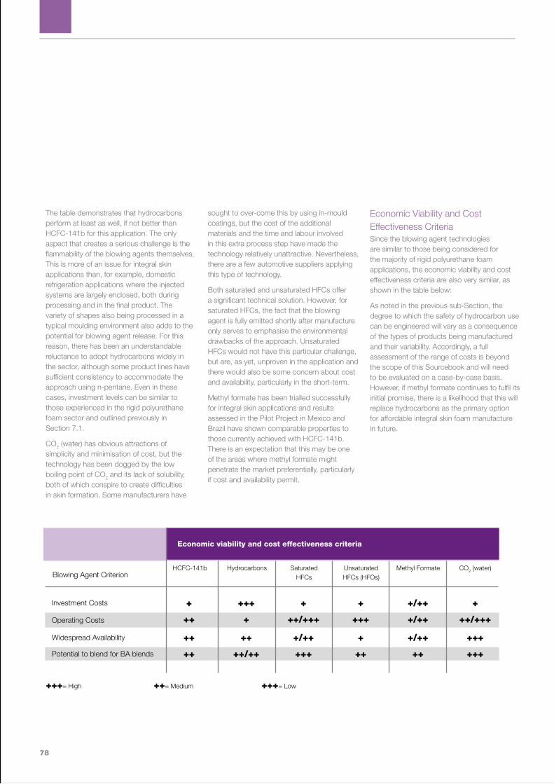
78
The table demonstrates that hydrocarbons perform at least as well, if not better than HCFC-141b for this application. The only aspect that creates a serious challenge is the flammability of the blowing agents themselves. This is more of an issue for integral skin applications than, for example, domestic refrigeration applications where the injected systems are largely enclosed, both during processing and in the final product. The variety of shapes also being processed in a typical moulding environment also adds to the potential for blowing agent release. For this reason, there has been an understandable reluctance to adopt hydrocarbons widely in the sector, although some product lines have sufficient consistency to accommodate the approach using n-pentane. Even in these cases, investment levels can be similar to those experienced in the rigid polyurethane foam sector and outlined previously in Section 7.1.
CO2 (water) has obvious attractions of simplicity and minimisation of cost, but the technology has been dogged by the low boiling point of CO2 and its lack of solubility, both of which conspire to create difficulties in skin formation. Some manufacturers have
sought to over-come this by using in-mould coatings, but the cost of the additional materials and the time and labour involved in this extra process step have made the technology relatively unattractive. Nevertheless, there are a few automotive suppliers applying this type of technology.
Both saturated and unsaturated HFCs offer a significant technical solution. However, for saturated HFCs, the fact that the blowing agent is fully emitted shortly after manufacture only serves to emphasise the environmental drawbacks of the approach. Unsaturated HFCs would not have this particular challenge, but are, as yet, unproven in the application and there would also be some concern about cost and availability, particularly in the short-term.
Methyl formate has been trialled successfully for integral skin applications and results assessed in the Pilot Project in Mexico and Brazil have shown comparable properties to those currently achieved with HCFC-141b. There is an expectation that this may be one of the areas where methyl formate might penetrate the market preferentially, particularly if cost and availability permit.
Economic Viability and Cost Effectiveness Criteria Since the blowing agent technologies are similar to those being considered for the majority of rigid polyurethane foam applications, the economic viability and cost effectiveness criteria are also very similar, as shown in the table below:
As noted in the previous sub-Section, the degree to which the safety of hydrocarbon use can be engineered will vary as a consequence of the types of products being manufactured and their variability. Accordingly, a full assessment of the range of costs is beyond the scope of this Sourcebook and will need to be evaluated on a case-by-case basis. However, if methyl formate continues to fulfil its initial promise, there is a likelihood that this will replace hydrocarbons as the primary option for affordable integral skin foam manufacture in future.
+ +++ + + +/++ +
++ + ++/+++ +++ +/++ ++/+++
++ ++ +/++ + +/++ +++
++ ++/++ +++ ++ ++ +++
HCFC-141b Hydrocarbons SaturatedHFCs
Unsaturated HFCs (HFOs)
Methyl Formate CO2 (water)
Investment Costs
Blowing Agent Criterion
Operating Costs
Widespread Availability
Potential to blend for BA blends
+++= High ++= Medium +++= Low
Economic viability and cost effectiveness criteria
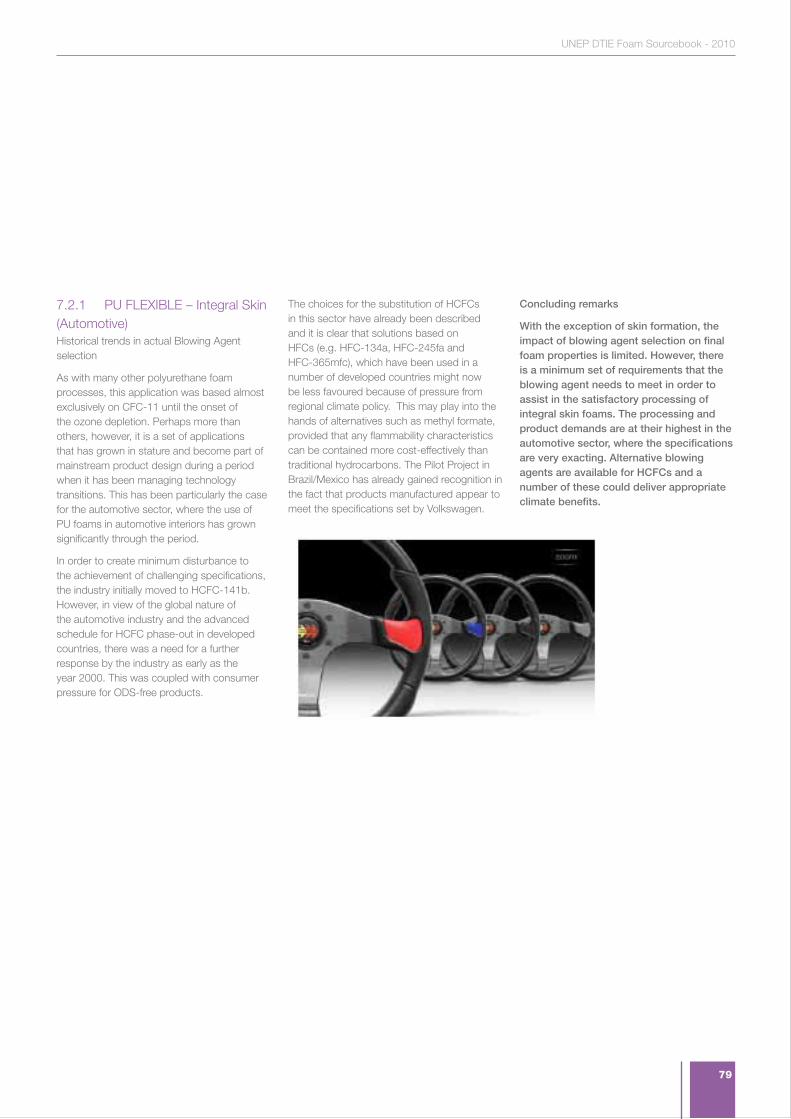
79
UNEP DTIE Foam Sourcebook - 2010
7.2.1 PU FLEXIBLE – Integral Skin (Automotive)Historical trends in actual Blowing Agent selection
As with many other polyurethane foam processes, this application was based almost exclusively on CFC-11 until the onset of the ozone depletion. Perhaps more than others, however, it is a set of applications that has grown in stature and become part of mainstream product design during a period when it has been managing technology transitions. This has been particularly the case for the automotive sector, where the use of PU foams in automotive interiors has grown significantly through the period.
In order to create minimum disturbance to the achievement of challenging specifications, the industry initially moved to HCFC-141b. However, in view of the global nature of the automotive industry and the advanced schedule for HCFC phase-out in developed countries, there was a need for a further response by the industry as early as the year 2000. This was coupled with consumer pressure for ODS-free products.
The choices for the substitution of HCFCs in this sector have already been described and it is clear that solutions based on HFCs (e.g. HFC-134a, HFC-245fa and HFC-365mfc), which have been used in a number of developed countries might now be less favoured because of pressure from regional climate policy. This may play into the hands of alternatives such as methyl formate, provided that any flammability characteristics can be contained more cost-effectively than traditional hydrocarbons. The Pilot Project in Brazil/Mexico has already gained recognition in the fact that products manufactured appear to meet the specifications set by Volkswagen.
Concluding remarks
With the exception of skin formation, the impact of blowing agent selection on final foam properties is limited. However, there is a minimum set of requirements that the blowing agent needs to meet in order to assist in the satisfactory processing of integral skin foams. The processing and product demands are at their highest in the automotive sector, where the specifications are very exacting. Alternative blowing agents are available for HCFCs and a number of these could deliver appropriate climate benefits.

80
7.2.2 PU FLEXIBLE – Integral Skin (Shoe Soles)This application is similar to other integral skin moulding applications, although the size and consistency of the products manufactured is much clearer. This allows for a higher degree of automation and engineering than in other sectors of the integral skin foam sector. Although shoe soles are a very well-defined application, the rate of change is driven by fashion considerations and, therefore, the manufacturing environment can be very dynamic. This has to be reflected in the versatility of equipment to changes in mould design and operation.
Historical trends in actual Blowing Agent selectionAgain, CFC-11 was the bedrock of this application in its early years, since it provided inert characteristics and met the processing demands without modification. When pressure emerged to phase-out the use of CFCs, there was some active consideration of HCFCs and some take-up of HCFC-141b. However, a significant proportion of the market realised that CO2 (water) would be a genuine option for this sector, since the processing hurdles were less challenging than those experienced with automotive products.
The industry is currently divided into these two camps and it is clear that those already using CO2 (water) have no particular incentive to move to other solutions. For those using HCFCs, however, the options include saturated HFCs (particularly HFC-134a), unsaturated HFCs and methyl formate. In developed countries, a number of manufacturers have already converted to HFC-134a despite its environmental profile and total instantaneous emission. Unsaturated HFCs would seem like an unlikely candidate in this application because of cost, but the way would remain open for methyl formate, based on recent test assessments within the Pilot Project.
Concluding remarks
This sector is already less reliant on HCFCs than most of the others covered in this Sourcebook and the remaining transition would not seem to represent a significant international challenge. With CO2 (water) technology already well established in large parts of the sector, the other technology options need to offer significant additional competitive advantages to gain market share. The use of saturated HFCs in the sector would appear avoidable and may be increasingly discouraged under future climate-policy frameworks.
7.3 PHENOLIC FOAMSPhenolic foams have been in existence since the middle part of the 20th century, but have only been used substantially in the insulation foam sector since the development of closed cell foam technology in the late 1970s and through the 1980s. Significant markets have developed in both Europe and Japan since then based on a combination of Boardstock and Block/Pipe products. The development of similar markets in North America was thwarted by poor experience with a specific roofing board technology (Koppers) that created corrosion problems on steel-decks. The primary benefits conveyed by phenolic foams are excellent thermal performance (see below) and intrinsic resistance to fire, with very low smoke generation.
A further application of phenolic foam has been as floral foam. When modified with appropriate surfactants, phenolic foams provide hydrophilic blocks that can be used to retain water in flowe r arrangements. The primary brand globally is known as ‘Oasis’. However, this material has never significantly been blown with ozone depleting substances, except in the case of small ‘me too’ producers. It is therefore not the prime focus of attention in this section.
Critical Foam Processing and Product PropertiesPhenolic chemistry differs from much of the polyurethane sector in that blowing agents are typically insoluble in the base resin. This means that the overall system is an emulsion and requires excellent mixing to create a uniform blend. The emulsion chemistry makes processing more sensitive, since the mix viscosity is higher than typical polyurethane systems. However, the benefit of emulsion chemistry is that small and very evenly distributed cell sizes can be achieved. In fact, this has led to some of the best performing foams from a thermal insulation perspective, since this is a net result of small, uniform cells. The dis-benefit of that same cell structure is that acoustic insulating properties are poor. Notwithstanding this, some polyisocyanutate foam producers have followed the phenolic lead and moved to emulsion systems.
Critical foam processing and product properties are very similar to those for rigid polyurethane foams and are depicted in the table below for the applications served by phenolics:
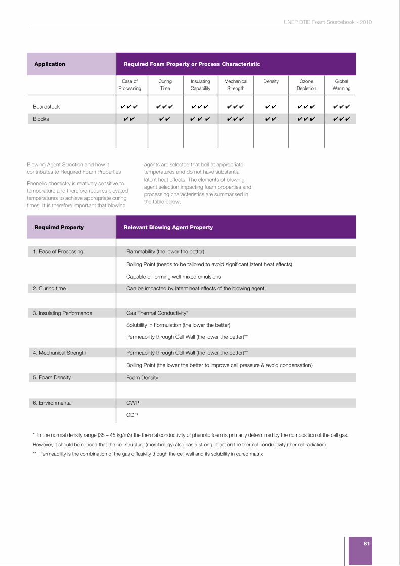
81
UNEP DTIE Foam Sourcebook - 2010
4 4 4 4 4 4 4 4 4 4 4 4 4 4 4 4 4 4 4 4
4 4 4 4 4 4 4 4 4 4 4 4 4 4 4 4 4 4
Ease of Processing
CuringTime
InsulatingCapability
Mechanical Strength
Density Ozone Depletion
Global Warming
Required Foam Property or Process CharacteristicApplication
Boardstock
Blocks
Blowing Agent Selection and how it contributes to Required Foam Properties
Phenolic chemistry is relatively sensitive to temperature and therefore requires elevated temperatures to achieve appropriate curing times. It is therefore important that blowing
agents are selected that boil at appropriate temperatures and do not have substantial latent heat effects. The elements of blowing agent selection impacting foam properties and processing characteristics are summarised in the table below:
Flammability (the lower the better)
Boiling Point (needs to be tailored to avoid significant latent heat effects)
Capable of forming well mixed emulsions
Can be impacted by latent heat effects of the blowing agent
Gas Thermal Conductivity*
Solubility in Formulation (the lower the better)
Permeability through Cell Wall (the lower the better)**
Permeability through Cell Wall (the lower the better)**
Boiling Point (the lower the better to improve cell pressure & avoid condensation)
Foam Density
GWP
ODP
Relevant Blowing Agent Property Required Property
1. Ease of Processing
2. Curing time
3. Insulating Performance
4. Mechanical Strength
5. Foam Density
6. Environmental
* In the normal density range (35 – 45 kg/m3) the thermal conductivity of phenolic foam is primarily determined by the composition of the cell gas.
However, it should be noticed that the cell structure (morphology) also has a strong effect on the thermal conductivity (thermal radiation).
** Permeability is the combination of the gas diffusivity though the cell wall and its solubility in cured matrix
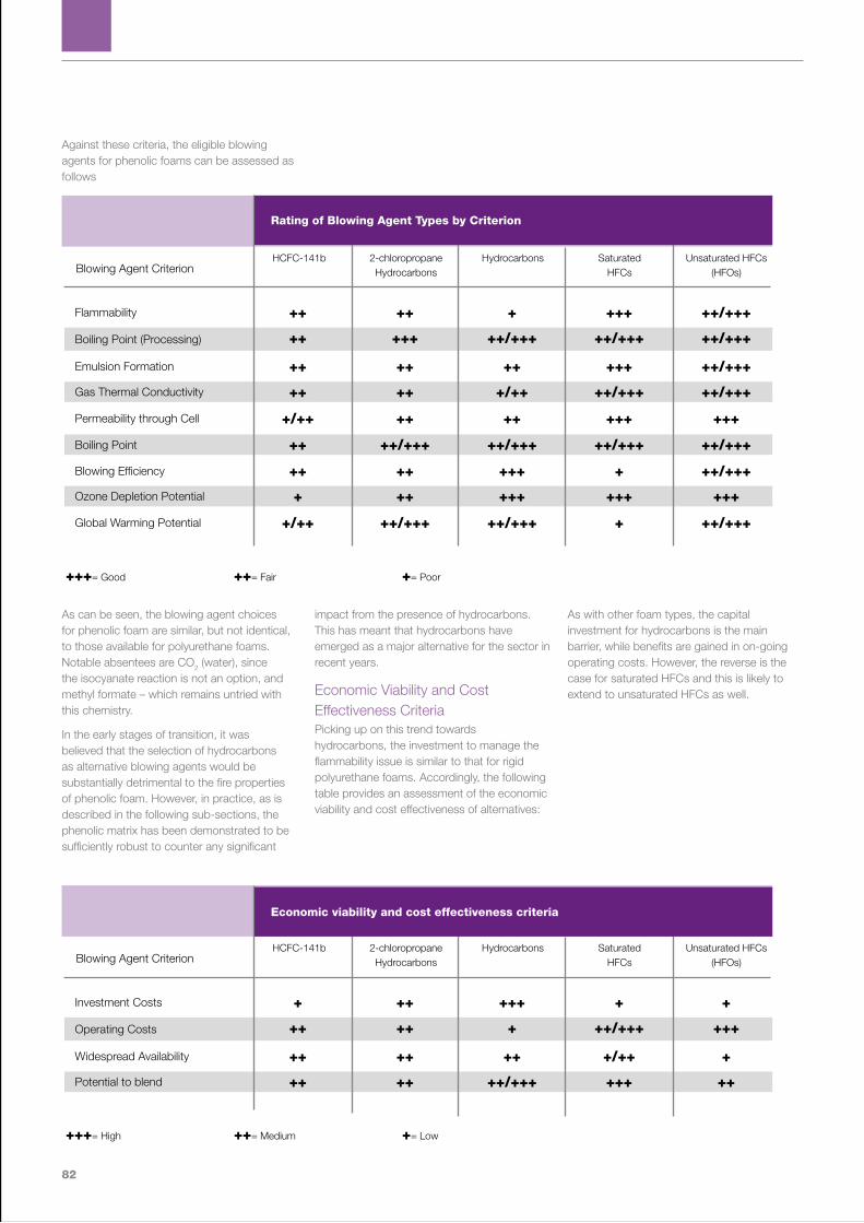
82
Against these criteria, the eligible blowing agents for phenolic foams can be assessed as follows
As can be seen, the blowing agent choices for phenolic foam are similar, but not identical, to those available for polyurethane foams. Notable absentees are CO2 (water), since the isocyanate reaction is not an option, and methyl formate – which remains untried with this chemistry.
In the early stages of transition, it was believed that the selection of hydrocarbons as alternative blowing agents would be substantially detrimental to the fire properties of phenolic foam. However, in practice, as is described in the following sub-sections, the phenolic matrix has been demonstrated to be sufficiently robust to counter any significant
impact from the presence of hydrocarbons. This has meant that hydrocarbons have emerged as a major alternative for the sector in recent years.
Economic Viability and Cost Effectiveness CriteriaPicking up on this trend towards hydrocarbons, the investment to manage the flammability issue is similar to that for rigid polyurethane foams. Accordingly, the following table provides an assessment of the economic viability and cost effectiveness of alternatives:
As with other foam types, the capital investment for hydrocarbons is the main barrier, while benefits are gained in on-going operating costs. However, the reverse is the case for saturated HFCs and this is likely to extend to unsaturated HFCs as well.
++ ++ + +++ ++/+++
++ +++ ++/+++ ++/+++ ++/+++
++ ++ ++ +++ ++/+++
++ ++ +/++ ++/+++ ++/+++
+ ++ +++ +++ +++
+/++ ++ ++ +++ +++
+/++ ++/+++ ++/+++ + ++/+++
++ ++/+++ ++/+++ ++/+++ ++/+++
++ ++ +++ + ++/+++
HCFC-141b 2-chloropropane Hydrocarbons
Hydrocarbons SaturatedHFCs
Unsaturated HFCs (HFOs)
Flammability
Blowing Agent Criterion
Boiling Point (Processing)
Emulsion Formation
Gas Thermal Conductivity
Ozone Depletion Potential
Permeability through Cell
Global Warming Potential
Boiling Point
Blowing Efficiency
+++= Good ++= Fair += Poor
+ ++ +++ + +
++ ++ + ++/+++ +++
++ ++ ++ +/++ +
++ ++ ++/+++ +++ ++
HCFC-141b 2-chloropropane Hydrocarbons
Hydrocarbons SaturatedHFCs
Unsaturated HFCs (HFOs)
Investment Costs
Blowing Agent Criterion
Operating Costs
Widespread Availability
Potential to blend
+++= High ++= Medium += Low
Rating of Blowing Agent Types by Criterion
Economic viability and cost effectiveness criteria

83
UNEP DTIE Foam Sourcebook - 2010
7.3.1 PHENOLIC – BoardstockAs noted in the introductory paragraphs of Section 7.3, the growth of the phenolic boardstock sector has been thwarted to an extent by technology issues in the North American market. However, the European market, and most notably the markets in the United Kingdom and Benelux have been able to press ahead with the commercialisation of technologies into this sector. The intrinsic fire, smoke and toxicity performance of the products coupled with their high degree of thermal performance has made them highly competitive with other forms of boardstock product in the marketplace. Market penetration has been assisted by the fluctuations in cost of various polyurethane raw materials and, more latterly, by the rapid growth in demand for boardstock products in general, as the thermal requirements in fixed-dimension cavity walls have increased.
This said, the geographic spread of phenolic boardstock production and use remains limited – partly because of the availability of technology and partly because of the precise processing parameters associated with these technologies. There are some less onerous technology options available, but these have not tended to meet the product performance required to make significant market in-roads.
Historical trends in actual Blowing Agent selectionThe traditional blowing agent for phenolic boardstock was CFC-11, although this was rapidly superseded by HCFC-141b. The use of HCFC-141b presented a particular challenge for the phenolic emulsion chemistry because of its solubility and the major technology holders found it necessary to modify the blowing agent with additives to make it less soluble in the foam mix.
In the transition that took place from HCFC-141b in Europe, it became self-evident that the phenolic product itself was sufficiently robust in its fire performance to accommodate hydrocarbon blowing agents for the bulk of end-uses. Therefore, the bulk of continuous processes are now based on n-pentane, either on its own or in blends with other hydrocarbons. One technology in Europe had moved directly from CFC-11 to 2-chloro-propane and continues to use this blowing agent as the basis for its product range.
There is limited use for saturated HFCs in these continuous processes, since thermal performance based on optimised hydrocarbon formulations is seen as sufficient for most end-uses.
Concluding remarks
Although it is not yet clear how the emergence of unsaturated HFCs might affect the blowing agent choices for future phenolic boardstock formulations, the overall performance of the various hydrocarbon-based technologies make it unlikely that there will be further technology transitions in the short term.
There has been little, if any, implementation of phenolic foam boardstock facilities in developing countries to date, so any future investment is likely to be based completely on technology transfer from Europe or elsewhere.
84
7.3.2 PHENOLIC – BlocksThe initial production of phenolic blocks pre-dated that of phenolic boardstock by at least 15 years. This was generally in the form of discontinuous blocks and was largely driven by the interest in floral foam. However, the use of block-based phenolic foams for a number of utilitarian uses in the panel sector began to emerge in the 1980s as the fire performance of the product began to be recognised.
The development of reliable closed-cell (low thermal conductivity) technologies in the early 1980s made the product much more competitive with other foam types as well as with mineral fibre. The particular market that opened up for phenolic block foam was the pipe section market in the UK, where fire performance precluded the use of polyurethane foams. The product was particularly successful and continues to hold a dominant market position in the non-domestic buildings market.
The comments on wastage highlighted in Section 7.1.8 also apply to the phenolic foam sector and this was of particular concern to the pipe section manufacturers. This has led to the more recent development of a continuous pipe section manufacturing process which avoids the high wastage levels for the most popular pipe sizes and thermal requirements.
Historical trends in actual Blowing Agent selectionAs with other phenolic foam product/process types, CFC-11 was the basic blowing agent of choice, except for the floral foam industry where the market leader developed a specific block foam technology based on hydrocarbon (n-pentane). This necessitated investment in risk reduction measures, which the company successfully implemented. In same cases, the boiling point of the blowing agent was modified by using CFC-11/CFC-113 blends in order to ensure the appropriate rise/cure profile. This was particularly important for phenolic chemistry where the sensitivity between temperature and cure rate is high. The reduction in the latent heat of evaporation in the early stages of the reaction helped to ensure appropriate processing times.
In similar fashion to the phenolic boardstock sector, the first transition was to HCFC-141b, with the same use of additives to reduce solubility of the blowing agent. In moving from HCFC-141b under the regulatory pressures in both Europe and North America, the industry initially moved to saturated HFCs. The choice was typically HFC-365mfc/227ea for boiling point reasons (as for CFC-11/CFC-113 blends). There is still a lack of widespread use of hydrocarbons in phenolic block processes for insulation purposes, although its use continues for floral foams.
As noted in the previous sub-section, the introduction of a continuous pipe section process has enabled reduction in foam losses, but has also enabled a switch in blowing agent to hydrocarbons, based on the more controllable environment. The bulk of phenolic pipe section supply in the UK is now based on this technology.
Concluding remarks
Phenolic foam continues to be something of a niche product in most global markets and has seen little success to date in developing countries. However, its innate potential continues to be recognised in a number of important and growing markets. In general terms, it is believed that any further development of a manufacturing base in developing countries will be supported by comprehensive technology transfer from one of the current technology holders.
As a consequence, there seems to be little requirement for support for the transition of existing phenolic foam facilities in developing countries.

85
UNEP DTIE Foam Sourcebook - 2010
4 4 4 4 4 4 4 4 4 4 4 4 4 4 4 4 4 4 4
4 4 4 4 4 4 4 4 4 4 4 4 4 4 4 4
4 4 4 4 4 4 4 4 4 4 4 4 4 4 4 4
Ease of Processing
MoistureResistance
InsulatingCapability
Mechanical Strength
Density Ozone Depletion
Global Warming
Required Foam Property or Process CharacteristicApplication
XPS – Board (Construction)
Polyolefin - Board (Other)
XPS – Board (Other)
7.4 THERMOPLASTIC FOAMSAs noted in Section 4.1, extruded thermoplastic foams are the only ones that have historically used ozone depleting substances. In the case of extruded polystyrene, products fall into two categories: ‘board’ and ‘sheet’, with ‘board’ being used for a variety of insulation, buoyancy and recreational activities, while ‘sheet’ has been focused on food and other packaging. Polyolefin (both polyethylene and polypropylene) foams have also found uses in these sectors, but the use of polyolefin foams in insulating applications has been more limited.
Equipment for the manufacture of extruded thermoplastic products varies substantially by region and application. In North America, where the primary requirement for extruded polystyrene is insulating sheathing boards for the residential construction market, the manufacturing lines tend to be long, for optimum speed and also capable of producing wide boards (typically 1.2 metres) at thicknesses down to 25mm. This requirement necessitates a substantial engineering solution and makes the transfer from one blowing agent to another very challenging.
In Europe, the requirements are more modest, with many lines generating product at a maximum of 0.6 metres in width and at greater thicknesses – often driven by the higher thermal insulation requirements of the commercial building sector. In South East Asia (most notably China), where the demand for extruded polystyrene foam is growing at its fastest, the technical and processing requirements are still more limited. In many cases, the polystyrene being used for extrusion has a high recycled content, making it less easy to process. Products generated in this scenario tend to be lower grade than in North America and Europe and are typically processed on 0.6 metre lines.
Critical Foam Processing and Product PropertiesExtruded thermoplastic foams provide some significant properties not available with rigid polyurethane foams. These include an extra measure of resilience and excellent moisture resistance. This makes them particularly suited for floor insulation in construction applications. The table below highlights these foam properties and reflects also the demanding nature of manufacture for the construction industry in some regions.
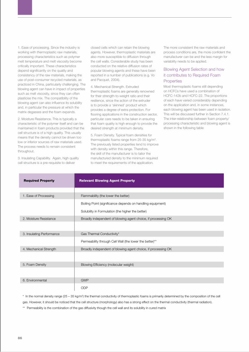
86
1. Ease of processing. Since the industry is working with thermoplastic raw materials, processing characteristics such as polymer melt temperature and melt viscosity become critically important. These characteristics depend significantly on the quality and consistency of the raw materials, making the use of post-consumer recycled materials, as practiced in China, particularly challenging. The blowing agent can have in impact of properties such as melt viscosity, since they can often plasticise the mix. The compatibility of the blowing agent can also influence its solubility and, in particular the pressure at which the matrix degasses and the foam expands.
2. Moisture Resistance. This is typically a characteristic of the polymer itself and can be maintained in foam products provided that the cell structure is of a high quality. This usually means that the density cannot be driven too low or inferior sources of raw materials used. The process needs to remain consistent throughout.
3. Insulating Capability. Again, high quality cell structure is a pre-requisite to deliver
closed cells which can retain the blowing agents. However, thermoplastic materials are also more susceptible to diffusion through the cell walls. Considerable study has been conducted on the relative diffusion rates of popular blowing agents and these have been reported in a number of publications (e.g. Vo and Pacquet, 2004).
4. Mechanical Strength. Extruded thermoplastic foams are generally renowned for their strength-to-weight ratio and their resilience, since the action of the extruder is to provide a ‘skinned’ product which provides a degree of extra protection. For flooring applications in the construction sector, particular care needs to be taken in ensuring that foam quality is high enough to provide the desired strength at minimum density.
5. Foam Density. Typical foam densities for thermoplastic foams range from 25-35 kg/m3. The previously listed properties tend to improve with density within this range. Therefore, the skill of the manufacturer is to tailor the manufactured density to the minimum required to meet the requirements of the application.
The more consistent the raw materials and process conditions are, the more confident the manufacturer can be and the less margin for variability needs to be applied.
Blowing Agent Selection and how it contributes to Required Foam PropertiesMost thermoplastic foams still depending on HCFCs have used a combination of HCFC-142b and HCFC-22. The proportions of each have varied considerably depending on the application and, in some instances, each blowing agent has been used in isolation. This will be discussed further in Section 7.4.1. The inter-relationship between foam property/processing characteristic and blowing agent is shown in the following table:
Flammability (the lower the better)
Boiling Point (significance depends on handling equipment)
Solubility in Formulation (the higher the better)
Broadly independent of blowing agent choice, if processing OK
Gas Thermal Conductivity*
Permeability through Cell Wall (the lower the better)**
Broadly independent of blowing agent choice, if processing OK
Blowing Efficiency (molecular weight)
GWP
ODP
Relevant Blowing Agent Property Required Property
1. Ease of Processing
2. Moisture Resistance
3. Insulating Performance
4. Mechanical Strength
5. Foam Density
6. Environmental
* In the normal density range (25 – 35 kg/m3) the thermal conductivity of thermoplastic foams is primarily determined by the composition of the cell
gas. However, it should be noticed that the cell structure (morphology) also has a strong effect on the thermal conductivity (thermal radiation).
** Permeability is the combination of the gas diffusivity though the cell wall and its solubility in cured matrix
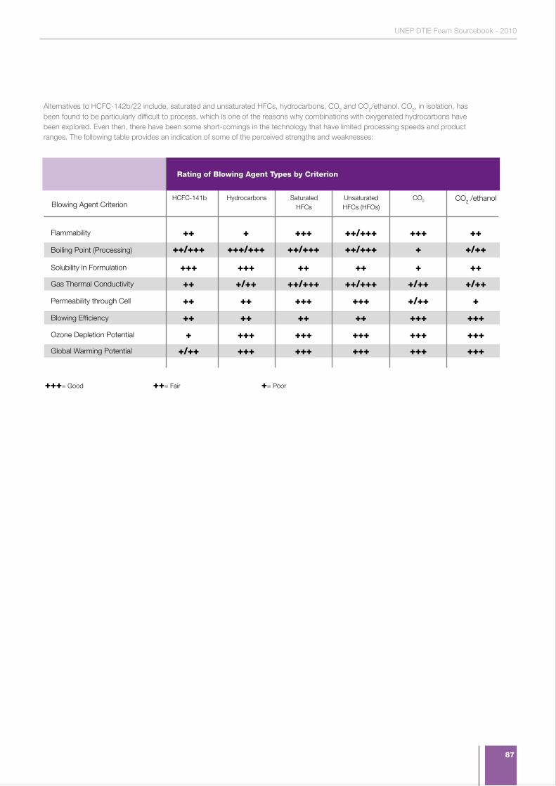
87
UNEP DTIE Foam Sourcebook - 2010
++ + +++ ++/+++ +++ ++
++/+++ +++/+++ ++/+++ ++/+++ + +/++
+++ +++ ++ ++ + ++
++ +/++ ++/+++ ++/+++ +/++ +/++
+/++ +++ +++ +++ +++ +++
++ ++ +++ +++ +/++ +
++ ++ ++ ++ +++ +++
+ +++ +++ +++ +++ +++
HCFC-141b Hydrocarbons SaturatedHFCs
Unsaturated HFCs (HFOs)
CO2 CO2 /ethanol
Flammability
Blowing Agent Criterion
Boiling Point (Processing)
Solubility in Formulation
Gas Thermal Conductivity
Global Warming Potential
Permeability through Cell
Blowing Efficiency
Ozone Depletion Potential
+++= Good ++= Fair += Poor
Alternatives to HCFC-142b/22 include, saturated and unsaturated HFCs, hydrocarbons, CO2 and CO2/ethanol. CO2, in isolation, has been found to be particularly difficult to process, which is one of the reasons why combinations with oxygenated hydrocarbons have been explored. Even then, there have been some short-comings in the technology that have limited processing speeds and product ranges. The following table provides an indication of some of the perceived strengths and weaknesses:
Rating of Blowing Agent Types by Criterion
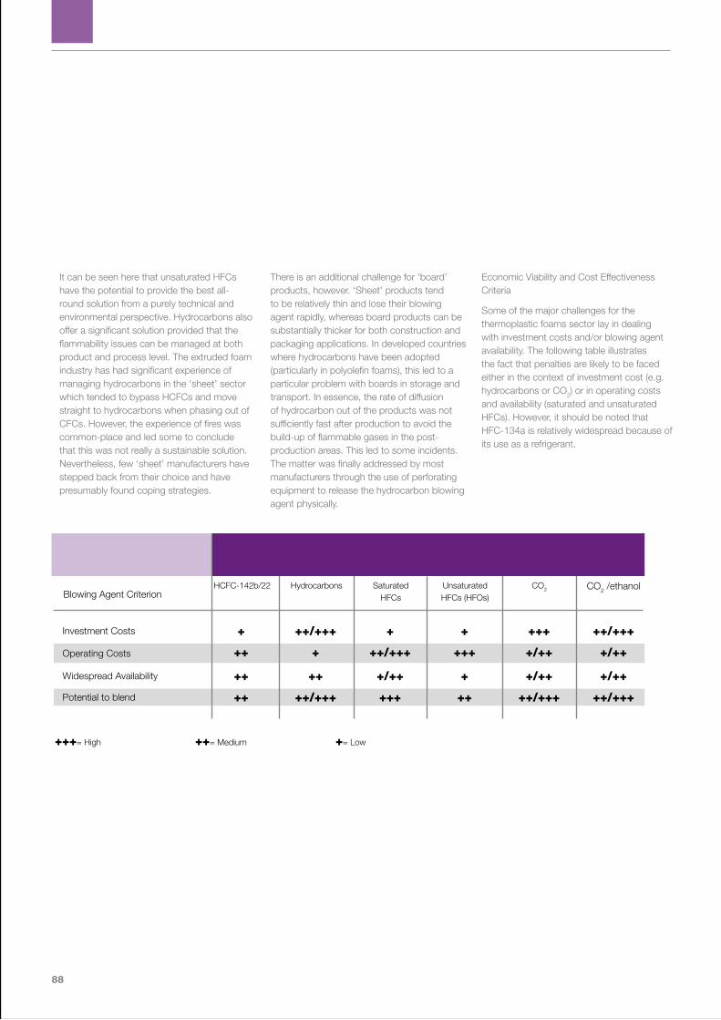
88
It can be seen here that unsaturated HFCs have the potential to provide the best all-round solution from a purely technical and environmental perspective. Hydrocarbons also offer a significant solution provided that the flammability issues can be managed at both product and process level. The extruded foam industry has had significant experience of managing hydrocarbons in the ‘sheet’ sector which tended to bypass HCFCs and move straight to hydrocarbons when phasing out of CFCs. However, the experience of fires was common-place and led some to conclude that this was not really a sustainable solution. Nevertheless, few ‘sheet’ manufacturers have stepped back from their choice and have presumably found coping strategies.
There is an additional challenge for ‘board’ products, however. ‘Sheet’ products tend to be relatively thin and lose their blowing agent rapidly, whereas board products can be substantially thicker for both construction and packaging applications. In developed countries where hydrocarbons have been adopted (particularly in polyolefin foams), this led to a particular problem with boards in storage and transport. In essence, the rate of diffusion of hydrocarbon out of the products was not sufficiently fast after production to avoid the build-up of flammable gases in the post-production areas. This led to some incidents. The matter was finally addressed by most manufacturers through the use of perforating equipment to release the hydrocarbon blowing agent physically.
Economic Viability and Cost Effectiveness Criteria
Some of the major challenges for the thermoplastic foams sector lay in dealing with investment costs and/or blowing agent availability. The following table illustrates the fact that penalties are likely to be faced either in the context of investment cost (e.g. hydrocarbons or CO2) or in operating costs and availability (saturated and unsaturated HFCs). However, it should be noted that HFC-134a is relatively widespread because of its use as a refrigerant.
+ ++/+++ + + +++ ++/+++
++ + ++/+++ +++ +/++ +/++
++ ++ +/++ + +/++ +/++
++ ++/+++ +++ ++ ++/+++ ++/+++
HCFC-142b/22 Hydrocarbons SaturatedHFCs
Unsaturated HFCs (HFOs)
CO2 CO2 /ethanol
Investment Costs
Blowing Agent Criterion
Operating Costs
Widespread Availability
Potential to blend
+++= High ++= Medium += Low

89
UNEP DTIE Foam Sourcebook - 2010
7.4.1 EXTRUDED POLYSTYRENE
– BoardAs noted in previous sections, the use of extruded polystyrene is primarily in the construction sector where it is used for a variety of insulation purposes, both in walls and roofs, but most notably in floors, where the product has specific competitive advantages. The product has competed successfully against both rigid polyurethane foams and mineral fibre in all the major regions of the world, although its mode of success has varied depending on the regional demand patterns. This point speaks to the versatility of extruded polystyrene in its application.
Historical trends in actual Blowing Agent selectionThe whole extruded thermoplastic foam sector was established on the ease of use of CFC-12 as a blowing agent. The blowing agent provided the inert character and thermal performance to deliver high quality products at affordable prices. It was only when the phase-out of CFCs was required that the split between choices for ‘board’ and ‘sheet’ materials occurred. As noted in Section 7.4, sheet products moved predominantly to hydrocarbons, while board products chose to use HCFC-142b/22 blends for the most part, in order to retain the requisite thermal performance.
When the blend was chosen, it was known that the cell wall permeability of HCFC-142b was significantly lower than that of HCFC-22. Therefore, the long-term thermal performance of products would largely be determined by the proportion of HCFC-142b in the blend and its subsequent retention. Since
HCFC-22 is a major refrigerant, its availability has been greater, and its price lower, throughout its period of use. This has been particularly important in some developing country regions where access to HCFC-142b has been more difficult and the cost significantly higher. Since some product and building codes will have been written around the sole use of HCFC-22, it may make the transitional hurdle a little easier when phase-out of HCFCs is finally embraced.
Concluding remarks
The extruded polystyrene sector is continuing to grow rapidly in China and elsewhere in Asia and practical transitional solutions will be essential. It seems unlikely that either saturated or unsaturated HFCs will make major in-roads in the markets for reasons of cost and availability. Therefore, the most likely solution will be based on hydrocarbons, on their own or in blends. The level of investment needed to support this is unclear, but, since the plants are relatively small, and there is parallel experience with extruded polystyrene sheet, it may be that the transition will be less challenging than currently envisaged. CO2 seems unlikely as a solution in isolation. The extrusion process remains highly emissive, and this puts a particular burden on the avoidance of high GWP solutions, such as saturated HFCs. The only time when such an approach might be justified is in applications and jurisdictions where thermal performance is absolutely paramount. In these cases, it may be possible to maker further transitions from saturated to unsaturated HFCs in due course.

90
7.4.2 POLYOLEFIN FOAMSPolyolefin foams have made less penetration into the construction markets that have been the bedrock of the extruded polystyrene industry. The one exception to this has been in the pipe insulation sector, where the added resilience offered by the product has proved of substantial value. The primary use for polyolefin foams has been as a high performance packaging material – particularly when used for the packaging of delicate, high value equipment.
Historical trends in actual Blowing Agent selectionThe choice of blowing in the polyolefin foam sector has followed a very similar pattern to that of extruded polystyrene foam. However, because of the lack of a large demand for insulating properties, the industry switched more fully to hydrocarbons when transitioning from CFCs. It therefore had to address some of the issues discussed in sub-Section 7.4 regarding the storage and transport of these products.
The remaining use of HCFCs in this product sector is much more limited than in the extruded polystyrene sector. Nevertheless, where use does exist – possibly in goods related to recreational applications – technical assistance may be necessary to ensure that appropriate precautions are taken in any final switch to hydrocarbons
Concluding remarks
The polyolefin foam sector is only seen to present a limited challenge in the efforts to phase of HCFCs under Decision XIX/6. It would appear that relevant climate-positive solutions are available and that widespread experience exists concerning their use. There maybe some, as yet, unidentified niche applications that could present more of a challenge, but no evident has yet emerged to this effect.

91
UNEP DTIE Foam Sourcebook - 2010
92
Section 8.Funding Strategies
“The provisions for the funding of HCFC phase-out investments are becoming clearer, although some aspects related to climate benefits remain uncertain”
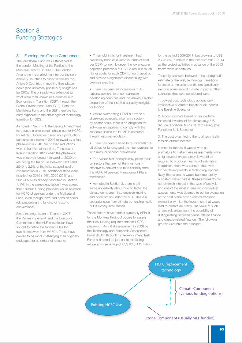
93
UNEP DTIE Foam Sourcebook - 2010
8.1 Funding the Ozone ComponentThe Multilateral Fund was established at the London Meeting of the Parties to the Montreal Protocol in 1990. The London Amendment signalled the intent of the non-Article 5 Countries to assist financially the Article 5 Countries in meeting their phase-down (and ultimately phase-out) obligations for CFCs. The principle was extended to what were then known as Countries with Economies in Transition (CEIT) through the Global Environment Fund (GEF). Both the Multilateral Fund and the GEF therefore had early exposure to the challenges of technology transition for ODS.
As noted in Section 1, the Beijing Amendment introduced a time-certain phase-out for HCFCs for Article 5 Countries based on a production/consumption freeze in 2016 followed by a final phase-out in 2040. No phased reductions were scheduled at that time. These came later in Decision XIX/6 when the phase-out was effectively brought forward to 2030 by restricting the tail of use between 2030 and 2040 to 2.5% of the initial capped level of consumption in 2013. Additional steps were inserted for 2015 (10%), 2020 (35%) and 2025 (65%) as already described in Section 1. Within the same negotiation it was agreed that a similar funding provision would be made for HCFC phase-out under the Multilateral Fund, even though there had been an earlier rule preventing the funding of ‘second conversions’.
Since the negotiation of Decision XIX/6, the Parties in general, and the Executive Committee of the MLF in particular, have sought to define the funding rules for transitions away from HCFCs. These have proved to be more challenging than originally envisaged for a number of reasons:
• Threshold limits for investment had previously been calculated in terms of cost per ODP- tonne. However, the lower ozone depletion potentials of HCFCs result in much higher costs for each ODP-tonne phased out and provide a significant discontinuity with previous practice.
• There has been an increase in multi-national ownership of companies in developing countries and this makes a higher proportion of the installed capacity ineligible for funding.
• Where overarching HPMPs provide a phase-out schedule, often on a sector-by-sector basis, there is no obligation for individual enterprises to comply with the schedule unless the HPMP is enforced through national regulation
• There has been a need to re-establish cut-off dates for funding and the inter-relationship with rules for second conversions
• The ‘worst-first’ principle may place focus on sectors that are not the most cost-effective to convert and take flexibility from the HCFC Phase-out Management Plans themselves.
• As noted in Section 3, there is still some uncertainty about how to factor the climate component into decision-making and prioritisation under the MLF. This is a separate issue from climate co-funding itself, but is closely inter-related.
These factors have made it extremely difficult for the Montreal Protocol bodies to assess the likely funding requirements for HCFC phase-out. An initial assessment in 2008 by the Technology and Economic Assessment Panel (TEAP) through its Replenishment Task Force estimated project costs (excluding refrigeration servicing) of US$ 66.5-115 million
for the period 2009-2011, but growing to US$ 238.3-357.5 million in the triennium 2012-2014 as the project activities in advance of the 2013 freeze were undertaken.
These figures were believed to be a pragmatic estimate of the likely technology transitions foreseen at the time, but did not specifically exclude some implicit climate impacts. Other scenarios that were considered were:
1. Lowest cost technology options only, irrespective of climate benefit or dis-benefit (the Baseline Scenario)
2. A cost estimate based on an available threshold investment for climate (e.g. US $20 per additional tonne of CO2 saved) (the Functional Unit Scenario)
3. The cost of achieving the total technically feasible climate benefits.
In most instances, it was viewed as premature to make these assessments since a high level of project analysis would be required to produce meaningful estimates. In addition, there was concern that, with further developments in technology options likely, the estimates would become rapidly outdated. Nevertheless, these arguments did not diminish interest in this type of analysis and one of the most interesting conceptual assessments was deemed to be the evaluation of the cost of the ozone-related transition element only – i.e. the investment that would lead to climate neutrality. The value of such an analysis arises from the possibility of distinguishing between ozone-related finance and climate-related finance. The following graphic illustrates the principle:
Ozone Component (Usually MLF funded)
Climate Component (various funding options)
Existing HCFC Use
HCFC replacementtechnology
Section 8. Funding Strategies

94
In taking this approach, there is an implicit assumption that climate co-funding can be made available to meet any additional cost related to further climate benefit. This can come in one of two forms: - (i) cost-coverage and (ii) market valuation. These are covered further in Section 8.2.
At the 60th Meeting of the Executive Committee in April 2010, the members were finally able to reach consensus on the basic rules relating to HCFC Projects. The primary items are as follows:
• The cut-off date agreed for eligibility of equipment for conversion is 21st September 2007. Equipment installed after that date will not qualify
• Second stage conversions will be accepted in the period to 2013, where projects can demonstrate that:
• They are essential for compliance with the 35% cut by 2020 and/or
• They represent the most cost-effective options for compliance
• Where neither of these criteria applies, funding will be limited to installation, trials and training
• In order to avoid dis-incentivising early action, countries can identify starting points prior to the baseline assessment in 2009-2010. These can relate to the point of HPMP submission or the date of project submission – whichever is the earliest. The starting points can be based on the last reported HCFC consumption under Article 7 on the Montreal Protocol or on the average of consumption forecast for 2009 and 2010.
With respect to incremental costs in achieving 2013 and 2015 targets, the following rules were established:
• The technical information in UNEP/OzL.Pro/ExCom/55/47 shall be used as a reference point for project preparation
• To overcome the impact of the lower ozone depleting potentials of HCFCs, the
previously established threshold limits for CFCs would be applied on a ‘per metric kg. basis’ for HCFCs, thereby taking the ODP issue out of the assessment.
• Up to 20% of the funding allocated for incremental operating costs can be transferred to cover incremental capital costs as long as this flexibility does not change the intent of the project.
• For the foam sector, the following thresholds were set:
• Incremental operating cost of US$1.60 per metric kg. of HCFC-141b
• Incremental operating cost of US$1.40 per metric kg. of HCFC-142b
• ExCom can award higher IOC levels for CO2 (water) projects
• Systems houses are able to calculate their allowances based on the total downstream uses of HCFCs.
All of these measures are seen to provide additional clarity to the funding scenarios for Article 5 countries as they seek to implement their HPMPs. However, perhaps the most striking of all of the measures agreed at the 60th Executive Committee meeting was a decision to allow additional funding amounting to 25% of the normal cost-effectiveness threshold for projects adopting low-GWP alternatives.
This development, whilst welcome in its intention to prioritise climate issues in the technology transitions occurring under Decision XIX/6, creates a number of additional questions based on the contents of this Foam Sourcebook. These include:
1. How will the term Low-GWP be defined in practice? The Report from TEAP responding to Decision XXI/9 provides some thinking in this area, including a cut-off point for ‘Low-GWP’ of 300, but it is not clear whether such an analysis will have any place in this type of funding regime.
2. How will the measure be aligned with the wider requirement of Decision XIX/6 to assess both energy and GWP aspects in its prioritisation of measures?
3. How will the provision of extra funding for apparent climate-beneficial technologies influence the ability of projects to seek climate co-funding from other sources (this matter is also touched on in Section 8.2)
4. How will the life cycle emissions characterisations included in the MCII be factored in to the climate funding mechanism, if at all?
These matters will be points of discussion for a number of months to come, but the initiative to promote projects with perceived climate benefits is clearly a significant one at this juncture.
95
UNEP DTIE Foam Sourcebook - 2010
8.2 Climate Co-Funding Opportunities within the Montreal Protocol Framework The Multilateral Fund of the Montreal Protocol provides financial assistance to Article 5 countries for the incremental costs of phasing out ozone depleting substances. The total incremental costs can include both agreed capital investment costs and incremental operating costs (IOCs). IOCs will generally only be met for a limited period after the technology transition is made.
In cases where the enterprise proposing the project would get additional benefits from a technology upgrade, the Multilateral Fund does not pay for such costs as they are not considered “incremental.” In such cases, the enterprise has to bring its own funding to cover the technology upgrade. However, this principle does not apply to climate benefits, which are viewed as in line with the objectives of the objectives of the accelerated HCFC phase-out.
Decision XIX/6 of the Meeting of the Parties encourages countries to select alternatives to HCFCs that minimize the climate impact. Decision XXI/9 taken at the 21st Meeting directs the Executive Committee of the Multilateral Fund “to consider providing additional funding and/or incentives for the additional climate benefits where appropriate….” This key decision, along with Decision XIX/6, gives quite clear guidance to include additional funding for projects that benefit both ozone layer and global climate. The provision of up to 25% additional funding for the introduction of low-GWP alternatives can be viewed as first step to obtain climate benefit from ozone layer protection projects.
The Multilateral Fund is considering the establishment of a Special Funding Facility for HCFC phase out projects which produce climate gains. The reader is advised to keep in contact with his/her country’s National Ozone Unit and the relevant Implementing Agency to understand the additional funding mechanism through the Special Funding Facility, as and when it is established.
Additional avenues for financing HCFC phase out projects that have climate benefitsA number of parallel, grant-financed and market-financed opportunities also exist for co-funding of climate benefits. These include:
• Voluntary Carbon Market (VCM) -supported by frameworks such as those provided through the Voluntary Carbon Standard;
• Pre-compliance Market - supported by frameworks such as those provided through the Climate Action Reserve ;
• Clean Development Mechanism (CDM) - in cases where the project results in improved energy efficiency;
• Global Environment Facility (GEF);
• Other donor-led funds - such as those that may emerge via the Copenhagen Accord
Since the options are evolving quickly, it is important that the reader discusses the applicability of these financing schemes with the National Ozone Unit and the relevant Implementing Agency. Some of these financing options are dependent on the existence of international regulatory frameworks, and attention must be paid to the rules and regulations of the respective mechanism.
1 The Climate Action Reserve activities also extend to the voluntary carbon market
96
Section 9.Conclusions
“The schedule established for HCFC phase-out creates pressure for the foam sector to act urgently”

97
UNEP DTIE Foam Sourcebook - 2010
This Sourcebook has hopefully provided relevant guidance on available technology options and the major factors that need to be considered in making technology selections. In doing so, it has illustrated the following:
• There are a number of emerging technologies that may provide optimal alternatives to HCFCs and may bypass the need for high GWP solutions
• In some sectors these alternatives may be well established, although they may require certain economies of scale to be justified under likely funding scenarios
• It seems likely that additional funding could be available to support the achievement of incremental climate benefits. However, the route by which these might be made available is still largely unclear and considerable further work may be required before these provisions can be finalised. The one exception to this is the 25% increase in incremental cost thresholds for low-GWP solutions under the Multilateral Fund
• Although there may be arguments to delay final technology decisions until the situation is clearer. However, the reality of the 2013 freeze in compliance terms and the impact of the ‘worst-first’ imperative on HCFC-141b projects may make such a delay a luxury that cannot be afforded within many HPMPs. In practice, there are a number of low GWP solutions already available.
Section 9. Conclusions
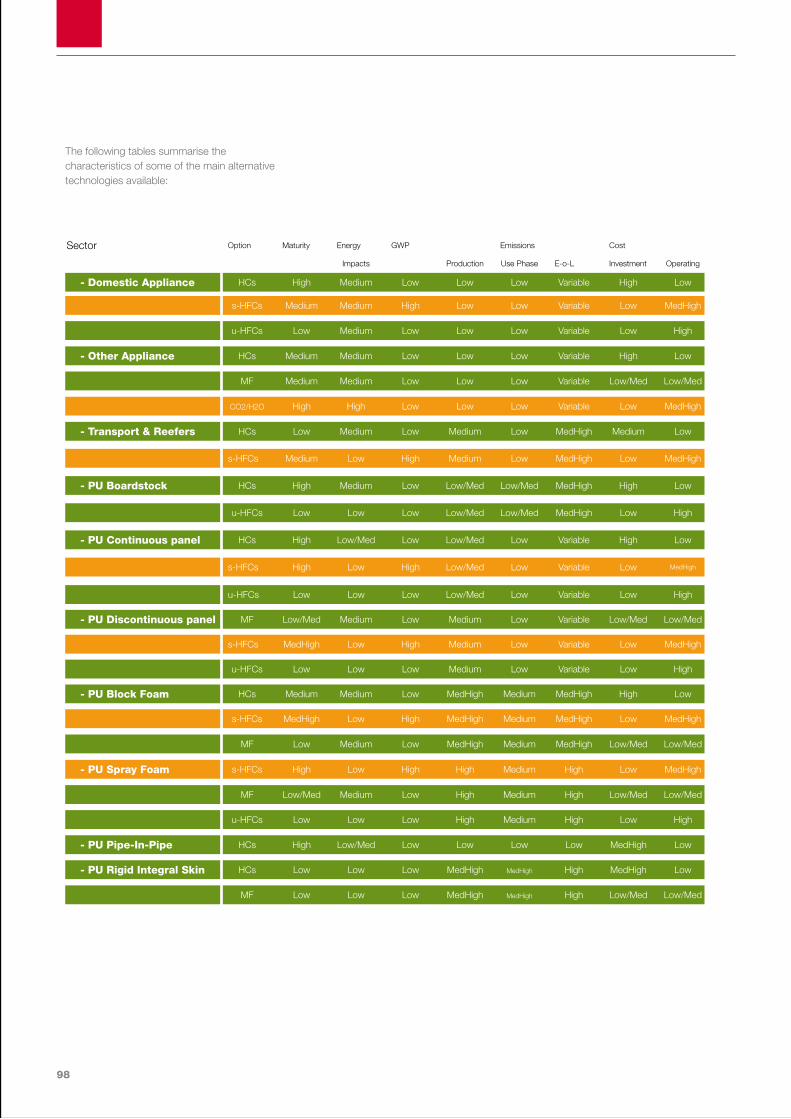
98
- Domestic Appliance
- PU Boardstock
- Other Appliance
- PU Pipe-In-Pipe
- PU Rigid Integral Skin
- PU Continuous panel
- PU Discontinuous panel
- PU Block Foam
- Transport & Reefers
- PU Spray Foam
The following tables summarise the characteristics of some of the main alternative technologies available:
Sector
HCs High Medium Low Low Low Variable High Low
Impacts Production Use Phase E-o-L Investment Operating
Option Maturity Energy GWP Emissions Cost
u-HFCs Low Medium Low Low Low Variable Low High
HCs High Medium Low Low/Med Low/Med MedHigh High Low
HCs Medium Medium Low Low Low Variable High Low
u-HFCs Low Low Low Low/Med Low/Med MedHigh Low High
u-HFCs Low Low Low Low/Med Low Variable Low High
u-HFCs Low Low Low Medium Low Variable Low High
MF Low Medium Low MedHigh Medium MedHigh Low/Med Low/Med
MF Low/Med Medium Low High Medium High Low/Med Low/Med
u-HFCs Low Low Low High Medium High Low High
HCs High Low/Med Low Low Low Low MedHigh Low
HCs Low Low Low MedHigh MedHigh High MedHigh Low
MF Low Low Low MedHigh MedHigh High Low/Med Low/Med
MF Medium Medium Low Low Low Variable Low/Med Low/Med
HCs High Low/Med Low Low/Med Low Variable High Low
MF Low/Med Medium Low Medium Low Variable Low/Med Low/Med
HCs Medium Medium Low MedHigh Medium MedHigh High Low
HCs Low Medium Low Medium Low MedHigh Medium Low
s-HFCs Medium Medium High Low Low Variable Low MedHigh
s-HFCs Medium Low High Medium Low MedHigh Low MedHigh
CO2/H2O High High Low Low Low Variable Low MedHigh
s-HFCs High Low High Low/Med Low Variable Low MedHigh
s-HFCs MedHigh Low High Medium Low Variable Low MedHigh
s-HFCs High Low High High Medium High Low MedHigh
s-HFCs MedHigh Low High MedHigh Medium MedHigh Low MedHigh
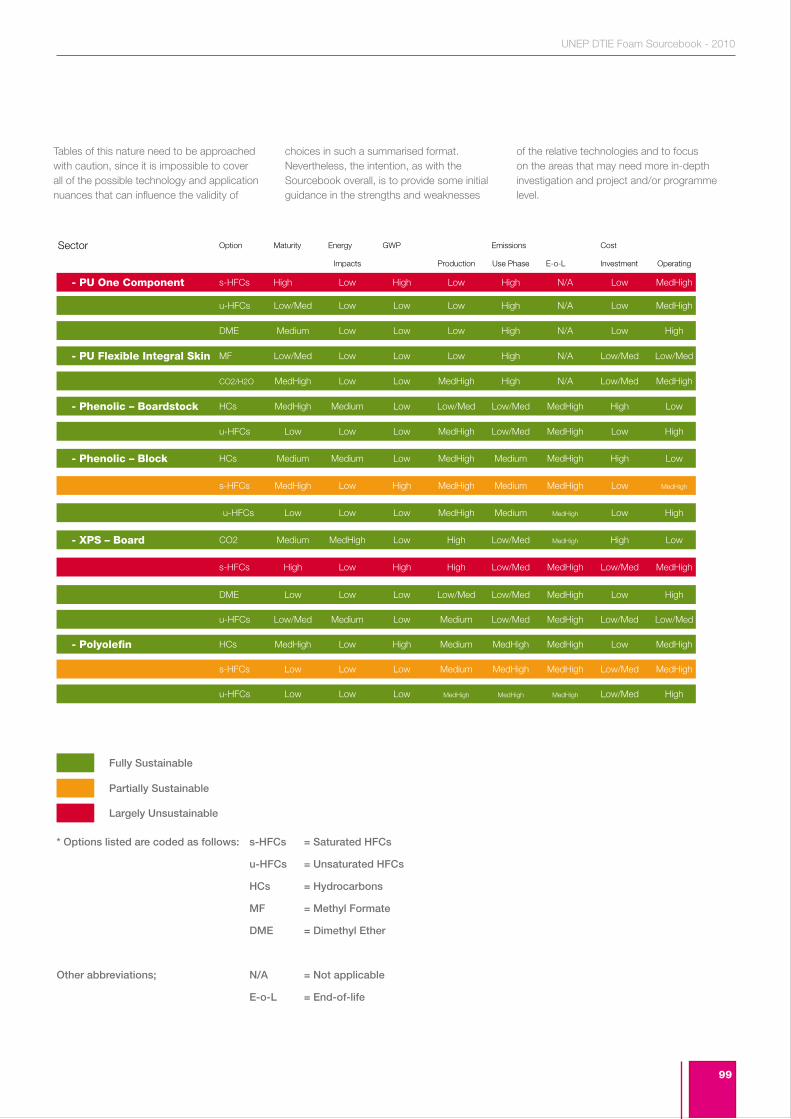
99
UNEP DTIE Foam Sourcebook - 2010
- PU One Component
- PU Flexible Integral Skin
- XPS – Board
- Phenolic – Block
- Phenolic – Boardstock
- Polyolefin
Tables of this nature need to be approached with caution, since it is impossible to cover all of the possible technology and application nuances that can influence the validity of
choices in such a summarised format. Nevertheless, the intention, as with the Sourcebook overall, is to provide some initial guidance in the strengths and weaknesses
of the relative technologies and to focus on the areas that may need more in-depth investigation and project and/or programme level.
Sector
s-HFCs High Low High Low High N/A Low MedHigh
Impacts Production Use Phase E-o-L Investment Operating
Option Maturity Energy GWP Emissions Cost
DME Medium Low Low Low High N/A Low High
s-HFCs MedHigh Low High MedHigh Medium MedHigh Low MedHigh
MF Low/Med Low Low Low High N/A Low/Med Low/Med
u-HFCs Low Low Low MedHigh Medium MedHigh Low High
DME Low Low Low Low/Med Low/Med MedHigh Low High
s-HFCs Low Low Low Medium MedHigh MedHigh Low/Med MedHigh
u-HFCs Low Low Low MedHigh MedHigh MedHigh Low/Med High
CO2/H2O MedHigh Low Low MedHigh High N/A Low/Med MedHigh
CO2 Medium MedHigh Low High Low/Med MedHigh High Low
u-HFCs Low/Med Medium Low Medium Low/Med MedHigh Low/Med Low/Med
u-HFCs Low Low Low MedHigh Low/Med MedHigh Low High
u-HFCs Low/Med Low Low Low High N/A Low MedHigh
HCs Medium Medium Low MedHigh Medium MedHigh High Low
HCs MedHigh Medium Low Low/Med Low/Med MedHigh High Low
s-HFCs High Low High High Low/Med MedHigh Low/Med MedHigh
HCs MedHigh Low High Medium MedHigh MedHigh Low MedHigh
Fully Sustainable
Partially Sustainable
Largely Unsustainable
* Options listed are coded as follows: s-HFCs = Saturated HFCs
u-HFCs = Unsaturated HFCs
HCs = Hydrocarbons
MF = Methyl Formate
DME = Dimethyl Ether
Other abbreviations; N/A = Not applicable
E-o-L = End-of-life

100
Section 10.Annexes
101
UNEP DTIE Foam Sourcebook - 2010
10.1 Sources of InformationThis Annex provides a Section-by-Section Guide to relevant references cited in the text. Where a reference is repeated in more than one Section, the reference itself is cited in full on its first occurrence, and is cross-referenced thereafter.
Summary
UNEP 2009. Handbook for the Montreal Protocol on Substances that Deplete the Ozone Layer, Eighth edition, ISBN: 9966-7319-0-3, United Nations Environment Programme, Nairobi, Kenya, 2009
Introduction
UNEP 2009. Handbook for the Montreal Protocol on Substances that Deplete the Ozone Layer, Eighth edition, ISBN: 9966-7319-0-3, United Nations Environment Programme, Nairobi, Kenya, 2009
Interface between Ozone Depletion and Climate Change
IPCC/TEAP. 2005. Special Report: Safeguarding the Ozone Layer and the Global Climate System, SROC 2005. Available at <http://www.autots.com/hcfc/technology%20option/Refrigeration/transport%20refrigeration.pdf>
IPCC, 2007. Fourth Assessment Report: Climate Change 2007 (AR4). Available at <http://www.ipcc.ch/pdf/assessment-report/ar4/wg1/ar4-wg1-chapter2.pdf>.
Methods for Quantifying Climate Impact
TEAP, 1999. The Implications to the Montreal Protocol of the inclusion of HFCs and PFCs in the Kyoto Protocol. Mar 2000.
Annex V of UNEP/OzL.Pro/ExCom/55/47. Revised analysis of relevant cost considerations surrounding the financing of HCFC phase-out (Decision 53/37(I) and 54/40).
Foam Manufacture and Existing Fluorocarbon Technologies
Lee Shau Tarng, C.B. Park and N.S. Ramesh, 2006. Polymeric Foams, CRC Press, New York.
IPCC/TEAP. 2005. Special Report: Safeguarding the Ozone Layer and the Global Climate System. Available at: <http://www.autots.com/hcfc/technology%20option/Refrigeration/transport%20refrigeration.pdf>
UNEP FTOC, 2002. Report of the Flexible and Rigid Foam Technical Options Committee, 2002 Assessment, ISBN 92-807-2285-9, UNEP/ Ozone Secretariat, Nairobi, Kenya, March 2003.
Khun E. and Schindler, P, 1993. Advances in the Understanding of the Effects of Various Blowing Agents on Rigid Polyurethane Appliance Foam Properties, SPI Polyurethanes World Congress 1993, Vancouver, BC, October 10-13.
Molina M.J. & Rowland F.S.,1974. Stratospheric sink for Chlorofluoromethanes – Chlorine atomic catalyzed destruction of ozone, Nature 249:810-812.
Oertel, Günter (editor), 1994. Polyurethane Handbook, 2nd. Edition, Carl Hanser Verlag, Munich.
UNEP/OzL.Pro/ExCom/55/47. Revised analysis of relevant cost considerations surrounding the financing of HCFC phase-out (Decision 53/37(I) and 54/40).
IPCC/TEAP. 2005. “Chapter 7: – Table 7.6” Special Report: Safeguarding the Ozone Layer and the Global Climate System, SROC 2005. Available at <http://www.autots. com/hcfc/technology%20option/Refrigeration/transport%20refrigeration.pdf>
Vo and Paquet, 2004. An Evaluation of Thermal Conductivity over time for Extruded Polystyrene Foams blown with HFC-134a and HCFC-142b
General Review of Alternative Blowing Agents
IPCC, 2007. Fourth Assessment Report: Climate Change 2007 (AR4). Available at <http://www.ipcc.ch/pdf/assessment-report/ar4/wg1/ar4-wg1-chapter2.pdf>.
Significant New Alternatives Program (SNAP), US Environmental Protection Agency http://www.epa.gov/ozone/snap/
IPCC/TEAP. 2005. Special Report: Safeguarding the Ozone Layer and the Global Climate System, SROC 2005. Available at <http://www.autots.com/hcfc/technology%20option/Refrigeration/transport%20refrigeration.pdf>
Section 10. Annexes
102
10.1 Sources of Information continued
Decision-making Process
TEAP Progress Report, 2008 UNEP Ozone Secretariat, Nairobi, Kenya, Available at: http://ozone.unep.org/Assessment_Panels/TEAP/Reports/TEAP_Reports/Teap_progress_report_May2008.pdf
Review of Specific Factors Influencing the Selection of Alternative Technologies at Application Level
Oertel, Günter (editor), 1994. Polyurethane Handbook, 2nd. Edition, Carl Hanser Verlag, Munich.
Dedecker, Kristof, 2002. Introduction to rigid foams, in Randall D. and Lee S., The Polyurethanes Handbook, Huntsman International, John Wiley & Sons, United Kingdom.
WORLD BANK- OORG, 2009. HCFC Replacement in Foams, Ozone Operations Resource Group (OORG), World Bank, Report 8/2009.
Deschaght, Joris, 2002. Appliances, in Randall D. and Lee S., The Polyurethanes Handbook, Huntsman International, John Wiley & Sons, United Kingdom.
DOW, 2008. Challenges to Replace ODS in PU Appliance Foams in Developing Countries, Presentation given by Dow Brazil in the European Seminar on HCFC alternatives for Foams, Montreal, April 5-6, 2008
AbiSaleh, T, Hernández, N and Hamilton, A, 2002. Other Construction Applications, in Randall D. and Lee S., The Polyurethanes Handbook, Huntsman International, John Wiley & Sons, United Kingdom.
UNEP FTOC, 2006. Report of the Flexible and Rigid Foam Technical Options Committee, 2006 Assessment, ISBN 978-92-807-2826-2, UNEP/ Ozone Secretariat, Nairobi, Kenya, March 2007.
Randall David and Steve Lee (editors), 2002.The Polyurethanes Handbook, Huntsman International, John Wiley & Sons, United Kingdom.
Gum, W, Wolfram, R and Henri Ulrich (editors), 1992. Reaction Polymers, Carl Hanser Verlag, Munich.
TEAP Progress Report, 2008 UNEP Ozone Secretariat, Nairobi, Kenya, Available at: http://ozone.unep.org/Assessment_Panels/TEAP/Reports/TEAP_Reports/Teap_progress_report_May2008.pdf
UNEP FTOC, 2006. Report of the Flexible and Rigid Foam Technical Options Committee, 2006 Assessment, ISBN 978-92-807-2826-2, UNEP/ Ozone Secretariat, Nairobi, Kenya, March 2007.
Bogdan, Mary C. and J.Y.K. Ling and D.J. Williams, 2009. Next Generation (LGWP) of Blowing Agents for Spray Foam Applications, Polyurethanes 2009, Technical Conference, October 5-7, 2009, Gaylord National, National Harbor, Maryland (Washington D.C.).
Funding Strategies
TEAP, 2008. The TEAP Replenishment Task Force - An initial assessment: Volume 2 Assessment of the funding requirement for the replenishment of the Multilateral Fund for the period 2009-2011. May 2008.
UNEP/OzL.Pro/ExCom/55/47. Revised analysis of relevant cost considerations surrounding the financing of HCFC phase-out (Decision 53/37(I) and 54/40).
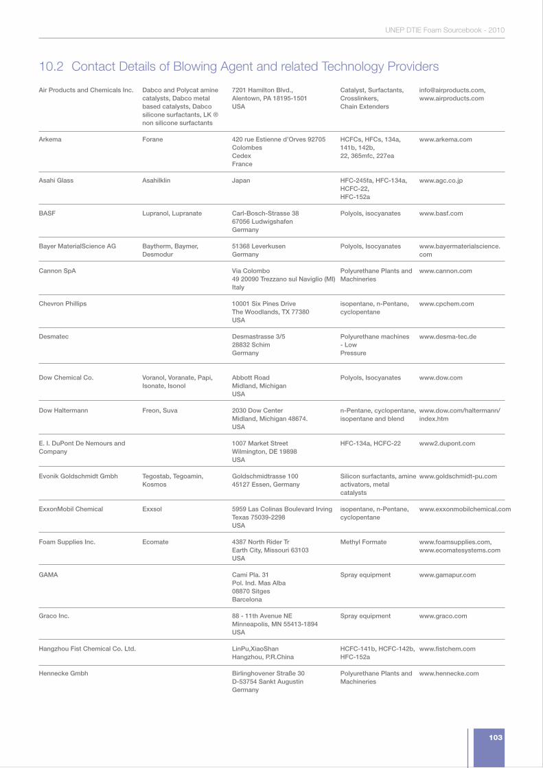
103
UNEP DTIE Foam Sourcebook - 2010
Air Products and Chemicals Inc.
Arkema
Asahi Glass
BASF
Bayer MaterialScience AG
Cannon SpA
Chevron Phillips
Desmatec
Dow Chemical Co.
Dow Haltermann
E. I. DuPont De Nemours and Company
Evonik Goldschmidt Gmbh
ExxonMobil Chemical
Foam Supplies Inc.
GAMA
Graco Inc.
Hangzhou Fist Chemical Co. Ltd.
Hennecke Gmbh
Dabco and Polycat amine catalysts, Dabco metal based catalysts, Dabco silicone surfactants, LK ® non silicone surfactants
Forane
Asahilklin
Lupranol, Lupranate
Baytherm, Baymer, Desmodur
Voranol, Voranate, Papi, Isonate, Isonol
Freon, Suva
Tegostab, Tegoamin, Kosmos
Exxsol
Ecomate
7201 Hamilton Blvd.,Alentown, PA 18195-1501USA
420 rue Estienne d’Orves 92705 ColombesCedexFrance
Japan
Carl-Bosch-Strasse 3867056 LudwigshafenGermany
51368 LeverkusenGermany
Via Colombo49 20090 Trezzano sul Naviglio (MI)Italy
10001 Six Pines DriveThe Woodlands, TX 77380USA
Desmastrasse 3/528832 SchimGermany
Abbott RoadMidland, MichiganUSA
2030 Dow CenterMidland, Michigan 48674.USA
1007 Market StreetWilmington, DE 19898USA
Goldschmidtrasse 10045127 Essen, Germany
5959 Las Colinas Boulevard IrvingTexas 75039-2298USA
4387 North Rider TrEarth City, Missouri 63103USA
Camí Pla. 31Pol. Ind. Mas Alba08870 SitgesBarcelona
88 - 11th Avenue NEMinneapolis, MN 55413-1894USA
LinPu,XiaoShanHangzhou, P.R.China
Birlinghovener Straße 30D-53754 Sankt AugustinGermany
Catalyst, Surfactants, Crosslinkers,Chain Extenders
HCFCs, HFCs, 134a, 141b, 142b,22, 365mfc, 227ea
HFC-245fa, HFC-134a, HCFC-22,HFC-152a
Polyols, isocyanates
Polyols, Isocyanates
Polyurethane Plants andMachineries
isopentane, n-Pentane,cyclopentane
Polyurethane machines - LowPressure
Polyols, Isocyanates
n-Pentane, cyclopentane,isopentane and blend
HFC-134a, HCFC-22
Silicon surfactants, amineactivators, metal catalysts
isopentane, n-Pentane,cyclopentane
Methyl Formate
Spray equipment
Spray equipment
HCFC-141b, HCFC-142b, HFC-152a
Polyurethane Plants andMachineries
[email protected], www.airproducts.com
www.arkema.com
www.agc.co.jp
www.basf.com
www.bayermaterialscience. com
www.cannon.com
www.cpchem.com
www.desma-tec.de
www.dow.com
www.dow.com/haltermann/ index.htm
www2.dupont.com
www.goldschmidt-pu.com
www.exxonmobilchemical.com
www.foamsupplies.com,www.ecomatesystems.com
www.gamapur.com
www.graco.com
www.fistchem.com
www.hennecke.com
10.2 Contact Details of Blowing Agent and related Technology Providers
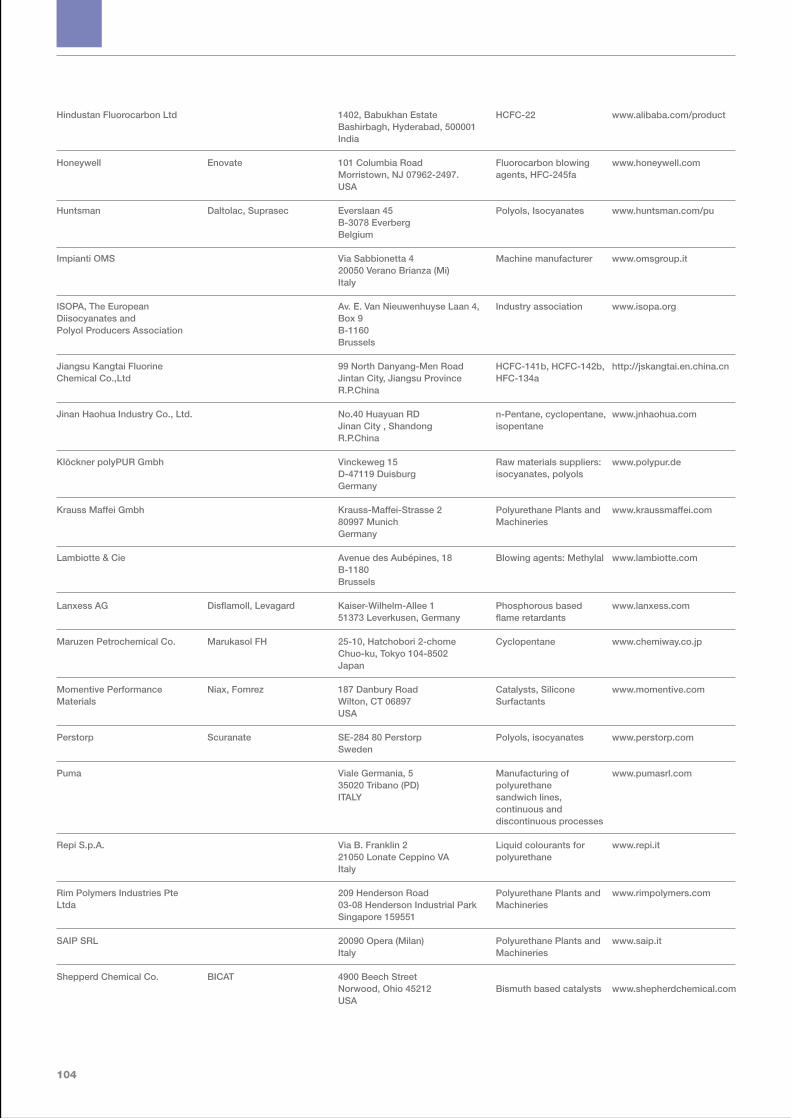
104
Hindustan Fluorocarbon Ltd
Honeywell
Huntsman
Impianti OMS
ISOPA, The European Diisocyanates andPolyol Producers Association
Jiangsu Kangtai Fluorine Chemical Co.,Ltd
Jinan Haohua Industry Co., Ltd.
Klöckner polyPUR Gmbh
Krauss Maffei Gmbh
Lambiotte & Cie
Lanxess AG
Maruzen Petrochemical Co.
Momentive Performance Materials
Perstorp
Puma
Repi S.p.A.
Rim Polymers Industries Pte Ltda
SAIP SRL
Shepperd Chemical Co.
Enovate
Daltolac, Suprasec
Disflamoll, Levagard
Marukasol FH
Niax, Fomrez
Scuranate
BICAT
1402, Babukhan EstateBashirbagh, Hyderabad, 500001India
101 Columbia RoadMorristown, NJ 07962-2497.USA
Everslaan 45B-3078 EverbergBelgium
Via Sabbionetta 420050 Verano Brianza (Mi)Italy
Av. E. Van Nieuwenhuyse Laan 4, Box 9B-1160Brussels
99 North Danyang-Men RoadJintan City, Jiangsu ProvinceR.P.China
No.40 Huayuan RDJinan City , ShandongR.P.China
Vinckeweg 15D-47119 DuisburgGermany
Krauss-Maffei-Strasse 280997 MunichGermany
Avenue des Aubépines, 18B-1180Brussels
Kaiser-Wilhelm-Allee 151373 Leverkusen, Germany
25-10, Hatchobori 2-chomeChuo-ku, Tokyo 104-8502Japan
187 Danbury RoadWilton, CT 06897USA
SE-284 80 PerstorpSweden
Viale Germania, 535020 Tribano (PD)ITALY
Via B. Franklin 221050 Lonate Ceppino VAItaly
209 Henderson Road03-08 Henderson Industrial ParkSingapore 159551
20090 Opera (Milan)Italy
4900 Beech StreetNorwood, Ohio 45212USA
HCFC-22
Fluorocarbon blowing agents, HFC-245fa
Polyols, Isocyanates
Machine manufacturer
Industry association
HCFC-141b, HCFC-142b, HFC-134a
n-Pentane, cyclopentane,isopentane
Raw materials suppliers:isocyanates, polyols
Polyurethane Plants andMachineries
Blowing agents: Methylal
Phosphorous based flame retardants
Cyclopentane
Catalysts, Silicone Surfactants
Polyols, isocyanates
Manufacturing of polyurethanesandwich lines, continuous anddiscontinuous processes
Liquid colourants for polyurethane
Polyurethane Plants andMachineries
Polyurethane Plants andMachineries
Bismuth based catalysts
www.alibaba.com/product
www.honeywell.com
www.huntsman.com/pu
www.omsgroup.it
www.isopa.org
http://jskangtai.en.china.cn
www.jnhaohua.com
www.polypur.de
www.kraussmaffei.com
www.lambiotte.com
www.lanxess.com
www.chemiway.co.jp
www.momentive.com
www.perstorp.com
www.pumasrl.com
www.repi.it
www.rimpolymers.com
www.saip.it
www.shepherdchemical.com

105
UNEP DTIE Foam Sourcebook - 2010
Solvay
Stepan
Supresta
Tosoh Corporation
Yantai Wanhua Polyurethanes Co.
Zhejiang Lantian Enviromental ProtectionChemical Co.,Ltd.
Zhejiang Sanhuan Chemicals Co. Ltd.
Zhejiang Sanmei Chemical Ind. Co. Ltd.
Solkane
Stepanpol
Fyrol
Toyocoat
Wannate, Wanol, Waneflex
Frog
Rue du Prince Albert 33B-1050Brussels
22 West Frontage Rd.Northfield, IL 60093USA
420 Saw Mill River RoadArdsley, New York 10502USA
3-8-2, Shiba, Minato-kuTokyo 105-8623Japan
No. 7 South Xingfu RoadYantai,Shangdong ProvinceP.R.China
Hangzhou gulf fine chemical zoneshangyu, zhejiangR.P.China
YongKang,Zhejiang ProvinceP.R.China
Huchu Industry AreaWuyi CountyZhejiang ProvinceP.R.China.
HCFCs, HFCs, 134a, 141b, 142b,22, 365mfc, 227ea
Polyester polyols
Phosphorous based flame retardants for rigid and flexible foams
Amine Catalysts
MDI based Isocyanates, polyols,Thermoplastic Urethanes
HCFC-141b, HCFC-142b, HFC-245fa
HCFC-141b, HCFC-142b, HCFC-22, HFC-152a, HFC-134a
HCFC-141b, HCFC-142b, HCFC-22, HFC-152a, HFC227ea
www.solvayfluor.com
www.stepan.com
www.supresta.com
www.tosoh.com
www.ytpu.com
www.fltchem.com
www.sanhuanchemicals.com
www.sanmeichem.com
106
10.3 Full text of Decision XIX/6
F. Decision XIX/6: Adjustments to the Montreal Protocol with regard to Annex C, Group I, substances (hydrochlorofluorocarbons)
The Parties agree to accelerate the phase-out of production and consumption of hydrochlorofluorocarbons (HCFCs), by way of an adjustment in accordance with paragraph 9 of Article 2 of the Montreal Protocol and as contained in the annex to the present decision, on the basis of the following:
1. For Parties operating under paragraph 1 of Article 5 of the Protocol (Article 5 Parties), to choose as the baseline the average of the 2009 and 2010 levels of, respectively, consumption and production; and
2. To freeze, at that baseline level, consumption and production in 2013;
3. For Parties operating under Article 2 of the Protocol (Article 2 Parties) to have completed the accelerated phase-out of production and consumption in 2020, on the basis of the following reduction steps:
(a) By 2010 of 75 per cent;
(b) By 2015 of 90 per cent;
(c) While allowing 0.5 per cent for servicing the period 2020–2030;
4. For Article 5 Parties to have completed the accelerated phase-out of production and consumption in 2030, on the basis of the following reduction steps:
(a) By 2015 of 10 per cent;
(b) By 2020 of 35 per cent;
(c) By 2025 of 67.5 per cent;
(d) While allowing for servicing an annual average of 2.5per cent during the period 2030–2040;
5. To agree that the funding available through the Multilateral Fund for the Implementation of the Montreal Protocol in the upcoming replenishments shall be stable and sufficient to meet all agreed incremental costs to enable Article 5 Parties to comply with the accelerated phase-out schedule both for production and consumption sectors as set out above, and based on that understanding, to also direct the Executive Committee of the Multilateral Fund to make the necessary changes to the eligibility criteria related to the post-1995 facilities and second conversions;
6. To direct the Executive Committee, in providing technical and financial assistance, to pay particular attention to Article 5 Parties with low volume and very low volume consumption of HCFCs;
7. To direct the Executive Committee to assist Parties in preparing their phase-out management plans for an accelerated HCFC phase-out;
8. To direct the Executive Committee, as a matter of priority, to assist Article 5 Parties in conducting surveys to improve reliability in establishing their baseline data on HCFCs;
9. To encourage Parties to promote the selection of alternatives to HCFCs that minimize environmental impacts, in particular impacts on climate, as well as meeting other health, safety and economic considerations;
10. To request Parties to report regularly on their implementation of paragraph 7 of Article 2F of the Protocol;
11. To agree that the Executive Committee, when developing and applying funding criteria for projects and programmes, and taking into account paragraph 6, give priority to cost-effective projects and programmes which focus on, inter alia:
(a) Phasing-out first those HCFCs with higher ozone-depleting potential, taking into account national circumstances;
(b) Substitutes and alternatives that minimize other impacts on the environment, including on the climate, taking into account global-warming potential, energy use and other relevant factors;
(c) Small and medium-size enterprises;
12. To agree to address the possibilities or need for essential use exemptions, no later than 2015 where this relates to Article 2 Parties, and no later than 2020 where this relates to Article 5 Parties;
13. To agree to review in 2015 the need for the 0.5 per cent for servicing provided for in paragraph 3, and to review in 2025 the need for the annual average of 2.5 per cent for servicing provided for in paragraph 4 (d);
14. In order to satisfy basic domestic needs, to agree to allow for up to 10% of baseline levels until 2020, and, for the period after that, to consider no later than 2015 further reductions of production for basic domestic needs;
15. In accelerating the HCFC phase-out, to agree that Parties are to take every practicable step consistent with Multilateral Fund programmes, to ensure that the best available and environmentally-safe substitutes and related technologies are transferred from Article 2 Parties to Article 5 Parties under fair and most favourable conditions;
Annex to the decision on Adjustments to the Montreal Protocol with regard to Annex C, Group I, substances (hydrochlorofluorocarbons)
Adjustments agreed by the Nineteenth Meeting of the Parties relating to the controlled substances in group I of Annex C of the Montreal Protocol
The Nineteenth Meeting of the Parties to the Montreal Protocol on Substances that Deplete the Ozone Layer decides to adopt, in accordance with the procedure laid down in paragraph 9 of Article 2 of the Montreal Protocol, and on the basis of assessments made pursuant to Article 6 of the Protocol, the adjustments and reductions of production and consumption of the controlled substances in Group I of Annex C to the Protocol, as follows:
Article 2F: Hydrochlorofluorocarbons
1. The current paragraph 8 of Article 2F of the Protocol shall become paragraph 2, and the current paragraph 2 shall become paragraph 3.
2. The current paragraphs 3 to 6 shall be replaced by the following paragraphs, which shall be numbered paragraphs 4 to 6:
“4. Each Party shall ensure that for the twelve-month period commencing on 1 January 2010, and in each twelve-month period thereafter, its calculated level of consumption of the controlled substances in Group I of Annex C does not exceed, annually, twenty-five per cent of the sum referred to in paragraph 1 of this Article. Each Party producing one or more of these substances shall, for the same periods, ensure that its calculated level of production of the controlled substances in Group I of Annex C does not exceed, annually, twenty-five per cent of the calculated level referred to in paragraph 2 of this Article. However, in order to satisfy the basic domestic needs of the Parties operating under paragraph 1 of Article 5, its calculated level of production may exceed that limit by up to ten per cent of its calculated level of production of the controlled substances in Group I of Annex C as referred to in paragraph 2.
107
UNEP DTIE Foam Sourcebook - 2010
5. Each Party shall ensure that for the twelve-month period commencing on 1 January 2015, and in each twelve-month period thereafter, its calculated level of consumption of the controlled substances in Group I of Annex C does not exceed, annually, ten per cent of the sum referred to in paragraph 1 of this Article. Each Party producing one or more of these substances shall, for the same periods, ensure that its calculated level of production of the controlled substances in Group I of Annex C does not exceed, annually, ten per cent of the calculated level referred to in paragraph 2 of this Article. However, in order to satisfy the basic domestic needs of the Parties operating under paragraph 1 of Article 5, its calculated level of production may exceed that limit by up to ten per cent of its calculated level of production of the controlled substances in Group I of Annex C as referred to in paragraph 2.
6. Each Party shall ensure that for the twelve-month period commencing on 1 January 2020, and in each twelve-month period thereafter, its calculated level of consumption of the controlled substances in Group I of Annex C does not exceed zero. Each Party producing one or more of these substances shall, for the same periods, ensure that its calculated level of production of the controlled substances in Group I of Annex C does not exceed zero. However:
i. each Party may exceed that limit on consumption by up to zero point five per cent of the sum referred to in paragraph 1 of this Article in any such twelve-month period ending before 1 January 2030, provided that such consumption shall be restricted to the servicing of refrigeration and air conditioning equipment existing on 1 January 2020;
ii. each Party may exceed that limit on production by up to zero point five per cent of the average referred to in paragraph 2 of this Article in any such twelve-month period ending before 1 January 2030, provided that such production shall be restricted to the servicing of refrigeration and air conditioning equipment existing on 1 January 2020.”
Article 5: Special situation of developing countries
3. The current sub-paragraphs (a) and (b) of paragraph 8 ter of Article 5 shall be replaced by the following sub-paragraphs, which shall become sub-paragraphs (a) to (e):
“(a) Each Party operating under paragraph 1 of this Article shall ensure that for the twelve-month period commencing on 1 January 2013, and in each twelve-month period thereafter, its calculated level of consumption of the controlled substances in Group I of
Annex C does not exceed, annually, the average of its calculated levels of consumption in 2009 and 2010. Each Party operating under paragraph 1 of this Article shall ensure that for the twelvemonth period commencing on 1 January 2013 and in each twelve-month period thereafter, its calculated level of production of the controlled substances in Group I of Annex C does not exceed, annually, the average of its calculated levels of production in 2009 and 2010;
(b) Each Party operating under paragraph 1 of this Article shall ensure that for the twelve-month period commencing on 1 January 2015, and in each twelve-month period thereafter, its calculated level of consumption of the controlled substances in Group I of Annex C does not exceed, annually, ninety per cent of the average of its calculated levels of consumption in 2009 and 2010. Each such Party producing one or more of these substances shall, for the same periods, ensure that its calculated level of production of the controlled substances in Group I of Annex C does not exceed, annually, ninety per cent of the average of its calculated levels of production in 2009 and 2010.
(c) Each Party operating under paragraph 1 of this Article shall ensure that for the twelve-month period commencing on 1 January 2020, and in each twelve-month period thereafter, its calculated level of consumption of the controlled substances in Group I of Annex C does not exceed, annually, sixty-five per cent of the average of its calculated levels of consumption in 2009 and 2010. Each such Party producing one or more of these substances shall, for the same periods, ensure that its calculated level of production of the controlled substances in Group I of Annex C does not exceed, annually, sixty-five per cent of the average of its calculated levels of production in 2009 and 2010.
(d) Each Party operating under paragraph 1 of this Article shall ensure that for the twelve-month period commencing on 1 January 2025, and in each twelve-month period thereafter, its calculated level of consumption of the controlled substances in Group I of Annex C does not exceed, annually, thirty-two point five per cent of the average of its calculated levels of consumption in 2009 and 2010. Each such Party producing one or more of these substances shall, for the same periods, ensure that its calculated level of production of the controlled substances in Group I of Annex C does not exceed, annually, thirty-two point five per cent of the average of its calculated levels of production in 2009 and 2010.
(e) Each Party operating under paragraph 1 of this Article shall ensure that for the twelve-month period commencing on 1 January 2030, and in each twelve-month period thereafter, its calculated level of consumption of the controlled substances in Group I of Annex C does not exceed zero . Each such Party producing one or more of these substances shall, for the same periods, ensure that its calculated level of production of the controlled substances in Group I of Annex C does not exceed zero. However:
i. each such Party may exceed that limit on consumption in any such twelve-month period so long as the sum of its calculated levels of consumption over the ten-year period from 1 January 2030 to 1 January 2040, divided by ten, does not exceed two point five per cent of the average of its calculated levels of consumption in 2009 and 2010, and provided that such consumption shall be restricted to the servicing of refrigeration and air conditioning equipment existing on 1 January 2030;
ii. each such Party may exceed that limit on production in any such twelve-month period so long as the sum of its calculated levels of production over the ten-year period from 1 January 2030 to 1 January 2040, divided by ten, does not exceed two point five per cent of the average of its calculated levels of production
in 2009 and 2010, and provided that such production shall be restricted to the servicing of refrigeration and air conditioning equipment existing on 1 January 2030.”
4. The current sub-paragraphs (c) and (d) of paragraph 8 ter of Article 5 shall become subparagraphs (f) and (g).
About the UNEP Division of Technology,
Industry and Economics
The UNEP Division of Technology, Industry and Economics (DTIE) helps
governments, local authorities and decision-makers in business and
industry to develop and implement policies and practices focusing on
sustainable development.
The Division works to promote:
> sustainable consumption and production,
> the efficient use of renewable energy,
> adequate management of chemicals,
> the integration of environmental costs in development policies.
The Office of the Director, located in Paris, coordinates activities
through:
> The International Environmental Technology Centre - IETC (Osaka, Shiga),
which implements integrated waste, water and disaster management programmes,
focusing in particular on Asia.
> Sustainable Consumption and Production (Paris), which promotes sustainable
consumption and production patterns as a contribution to human development through
global markets.
> Chemicals (Geneva), which catalyzes global actions to bring about the sound
management of chemicals and the improvement of chemical safety worldwide.
> Energy (Paris), which fosters energy and transport policies for sustainable development and encourages investment in renewable energy and energy efficiency.
> OzonAction (Paris), which supports the phase-out of ozone depleting substances in developing countries and countries with economies in transition to ensure implementation of the Montreal Protocol.
> Economics and Trade (Geneva), which helps countries to integrate environmental considerations into economic and trade policies, and works with the finance sector to incorporate sustainable development policies.
UNEP DTIE activities focus on raising awareness, improving
the transfer of knowledge and information, fostering
technological cooperation and partnerships, and implementing
international conventions and agreements.
For more information,
see www.unep.fr
ph
as
e-o
ut o
f h
cfs in
th
e f
le
xib
le a
nd r
igid
fo
am
se
ct
or
Address
For more information, contact:
UNEP DTIE
OzonAction Branch
15, rue de Milan
75441 Paris Cedex 09
France
Tel: +33 1 4437 1450
Fax: +33 1 4437 1474
E-mail: [email protected]
www.unep.fr/ozonaction
In September 2007, the 19th Meeting of the Parties to the Montreal Protocol agreed to Decision XIX/6, which advances the phase-out dates for HCFC production and consumption in developing countries. That Decision gives priority to adopting substitutes and alternatives that minimize other impacts on the environment, including on the climate, taking into account global-warming potential (GWP), energy use and other relevant factors. The UNEP DTIE OzonAction Programme has developed this publication to provide National Ozone Units and industry managers/owners guidance in selecting the appropriate alternative technology in the flexible and rigid foam sector. The document gives a brief introduction and description of the concerned sub-sectors and available technology options, as per the findings and recommendations based on the findings of the Foam Technical Options Committee and covering all of the uses of HCFCs in the manufacture of flexible and rigid foams. Guidance is also provided on how an enterprise in a developing country should select alternatives to HCFCs, with particular emphasis on minimizing the climate impact, including a practical and simplified methodology for assessing the climate impact of alternatives as compared to HCFCs as well as sourcing information for commercially-available technology. This publication is part of a larger set of enabling tools targeted to assist decision makers and industry players in meeting the accelerated phase out of HCFCs, and assisting key stakeholders in developing countries to make informed technology choices in accordance with Decision XIX/6.