guidance on minor railwaysrailway safety...
TRANSCRIPT
GUIDANCE ON MINOR RAILWAYSRailway Safety Publication 5


GUIDANCE ON MINOR RAILWAYS
Railway Safety Publication

2
First published by the Health and Safety Executive, 2005
Second edition published by the Office of Rail Regulation, 2007
This guidance is issued by the Office of Rail Regulation. Following the guidance is not compulsory and you are free to take other action. But if you do follow the guidance you will normally be doing enough to comply with the law. Railway inspectors seek to secure compliance with the law and may refer to this guidance as illustrating good practice.
3
Contents
FOREWORD 6
1 INTRODUCTION 7
Application of the guidance 7
Effects on existing works 7
Operating conditions 7
Design and building 8
Approval procedures 8
Minor railways - definition 8
Objective and scope 9
Compatibility 10
Terminology 11
2 THE TRACK 12
Ballast 12
Sleepers 13
Rails 13
Turnouts or points 15
Turntables 16
Lineside structures and equipment 16
Lineside paths and places of safety 17
3 EARTHWORKS, EMBANKMENTS AND CUTTINGS 19
4 BRIDGES, VIADUCTS AND TUNNELS 20
Bridges and viaducts carrying the railway (underline bridges) 20
Bridges and viaducts over the railway (overline bridges) 21
Parapets 21
4
Pipe bridges 22
Tunnels 22
5 INFRASTRUCTURE CLEARANCES 23
Clearances for train and passenger safety 23
Clearances between trains 23
Clearances required for staff safety 24
Typical structure gauge 24
6 INFRASTRUCTURE ACCESS CONTROL 27
Fencing 27
Access to the railway 27
Adjacent highways 28
7 IDENTIFICATION OF THE INFRASTRUCTURE 29
8 STATIONS 30
Station platforms 30
Other public areas in stations 31
Stairways, steps and ramps 32
9 SIGNALLING SYSTEMS 34
Communications 34
Choice of signalling system 34
Train separation and detection 35
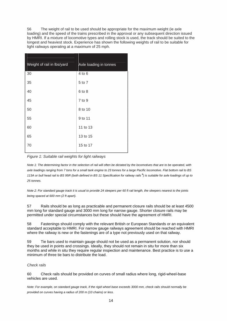
Single line working 36
Signals 38
Control of signalling 41
Interlocking of points and signals 42

5
10 LEVEL CROSSINGS 45
11 TRAINS 46
General guidance on trains 46
Wheels and brakes 47
Powered systems 49
Locomotives and other power units 50
Rolling stock 52
COMMON TERMS 56
REFERENCES 57
USEFUL LINKS 58
FURTHER INFORMATION 58
6
Foreword Soon after the formation of the Railway Inspectorate (now Her Majesty’s Railway Inspectorate (HMRI)) in 1840, the first written advice on the standards of construction for railway safety was issued. The advice was aimed at those who were building the new railways and outlined good practice that was acceptable to HMRI and provided consistency.
Over the years this advice on good practice has been extended to cover most aspects of railway construction. The last full review and updating took place in 1950 and was issued by the then Department of Transport as Railway Construction and Operation Requirements for Passenger lines and Recommendations for Goods Lines.
1 It became widely known throughout the railway industry
as the ‘Blue Book’ or simply the ‘Requirements’, although it was always intended to give advice and not to set an absolute standard.
Some parts of the Blue Book have since been revised and reissued, notably the sections on level crossings and structural clearances. Other parts of the document were clearly out of date and HMRI, in consultation with the rapidly changing railway industry, recognised that there was a need to provide advice in a different way and in a somewhat different format than the traditional ‘Requirements’.
The whole guidance was published as the Railway safety principles and guidance (RSPG).2 Part 1
of the series contains the top-level safety principles and gives an indication of the factors that need to be taken into account in implementing them. The sections that comprise Part 2 of the series (including this document) provide specific guidance on aspects of railway and tramway construction. They are:
A The infrastructure
B Stations
C Electric traction systems
D Signalling
E Level crossings
F Trains
G Tramways
H Minor railways
As with all guidance, these documents are intended to give advice and not set an absolute standard.
Each section of the Part 2 documents deals with specific aspects of railway construction, provides an expansion of the advice given in Part 1 and also gives examples of good practice acceptable to HMRI. It is hoped that this revised guidance will be as helpful as the Blue Book’s advice in the past. It is supplementary to legislation applicable to railways in England and Wales and also to that applicable to railways in Scotland.
During the development of these Part 2 documents there has been extensive consultation with the railway industry and other organisations. Much assistance and constructive comment has been received and HMRI is most grateful for all the time and help it has been given.
7
Introduction 1 Railway safety principles and guidance (RSPG)
2 are intended to give guidance and advice
to those involved in the design, construction and operation of new and altered works, plant and equipment capable of affecting the safety of railways, tramways or other guided transport systems, which require approval of the Secretary of State for Transport under the Railways and Other Transport Systems (Approval of Works, Plant and Equipment) Regulations 1994.
3
2 This document does not set out mandatory standards. It supports and amplifies the RSPG Part 1 by giving examples of established good practice, considered by HM Railway Inspectorate to provide an acceptable level of safety for the public (passengers and others), employees (including volunteers) and contractors.
Application of the guidance
3 Application of this guidance should provide a sufficient level of safety for approval to be given by HMRI, provided that it has been demonstrated that the use of the guidance is wholly applicable to the works, plant or equipment.
4 If this is not the case, then HMRI will wish to be satisfied that due consideration has been given to implementing the safety principles in the RSPG Part 1 in a way that ensures that all intolerable risks have been eliminated and that all remaining risks have been reduced to be as low as reasonably practicable (ALARP).
5 This document, Section H, applies to minor railways. The majority of these are light railways, constructed and previously run under the provisions of the Light Railways Act 1896,
4
which is still in force in Scotland. Since 1951 they have been restored, preserved, operated and maintained by volunteer bodies determined to preserve an important part of the nation’s history. While bound by current railway legislation, in the spirit of the 1896 Act, government regulation is less stringent for minor railways running at a maximum speed of 25 mph than it is for the commercial operators that run at up to five times that speed. A minor railway will not normally be permitted to operate above the traditional speed limit. Any intention to operate above 25 mph should be discussed with HMRI as soon as possible.
6 This document develops the safety principles given in the RSPG Part 1. It includes illustrations of systems that HMRI has previously found to be satisfactory. In so far as is reasonably practicable, the guidance outlined in this document should be applied when alterations or additions are made to existing minor railway systems, as well as when entirely new minor railway systems are installed. This document does not contain any specific advice on electric traction systems. Any minor railway wishing to use electric traction should seek advice from HMRI.
Effects on existing works
7 RSPG documents do not apply retrospectively to existing works, plant and equipment. However, new or altered works, plant and equipment might introduce incompatibilities or inconsistencies with the existing works, plant or equipment. In this case, approval may only be given if appropriate arrangements have been made to address these safety implications that may include modifications to the existing works, plant or equipment.
Operating conditions
8 The choice and design of the works, plant and equipment will depend not only on the guidance expressed in this document but also on the operational requirements of the railway.
9 In assessing the suitability of any proposed safety measures or arrangements, it is important to take into account:
(a) normal operating conditions;
8
(b) degraded conditions where any component or part of the railway materially affecting safety has failed;
(c) credible abnormal conditions to which the system may be subjected; and
(d) emergency situations.
Design and building
10 The guidance applies to the finished works, plant or equipment but not to the processes of designing or building. Designers and builders need to be aware of the responsibilities imposed upon them by the Construction (Design and Management) Regulations 1994 as amended.
5
11 This document covers any new or altered works, plant and equipment for minor railways. Their design and construction should take into account not only the safety of the railway’s users but also that of others who may be affected by the railway. Any additions or alterations to a railway should not degrade its level of safety.
12 While the regulations and the procedures referred to below are concerned primarily with the approval of the physical assets of a system (such as infrastructure and vehicles), HMRI will not grant approval without being satisfied that the procedures for the operation, management and maintenance of the equipment will be safe.
Approval procedures
13 Guidance on the procedures to be adopted, and the format of the documents to be submitted by those seeking approval of projects, is contained in the ORR publication Guide to the approval of railway works, plant and equipment
6
(http://www.rail-reg.gov.uk/upload/pdf/rotsguide.pdf).
14 Where different arrangements from those set out in this guidance are proposed, those responsible for submitting the works for approval will be expected to demonstrate that such arrangements provide an equivalent level of safety.
15 Where changes are proposed to works, plant or equipment already in use, the changes should follow this guidance where this is reasonably practicable rather than the earlier standards under which the existing works, plant or equipment were originally approved.
Minor railways - definition
16 This guidance is concerned with minor railways in Great Britain. A railway is defined in the Transport and Works Act 1992
7 as a system of transport employing parallel rails which:
(a) provide support and guidance for vehicles carried on flanged wheels; and
(b) form a track which either is of a gauge of at least 350 mm or crosses a public carriageway (whether or not on the same level), but does not include a tramway.
17 The term ‘minor’ is, for the purposes of this section of guidance, intended to refer to railways of any gauge which:
(a) have retained or have assumed the character and appearance and, where appropriate, operating practices of railways of former times, eg depict a railway branch line of former times; or
9
(b) may reflect no particular era but demonstrate a wide variety of motive power and rolling stock at work, irrespective of company (or country) of origin.
Note 1: The term ‘minor railways’ includes heritage railways, lines of local interest, museum railways and tourist railways.
Note 2: Some of these lines were of narrow gauge, built for a communal or industrial purpose, never nationalised but which
survived through the railway closure period to be run by volunteers today.
Note 3: Several lines that operate in isolation provide genuine transport facilities, providing links with the outside world for
communities cut off by snow or flood.
Note 4: Most lines constitute tourist or educational attractions in their own right.
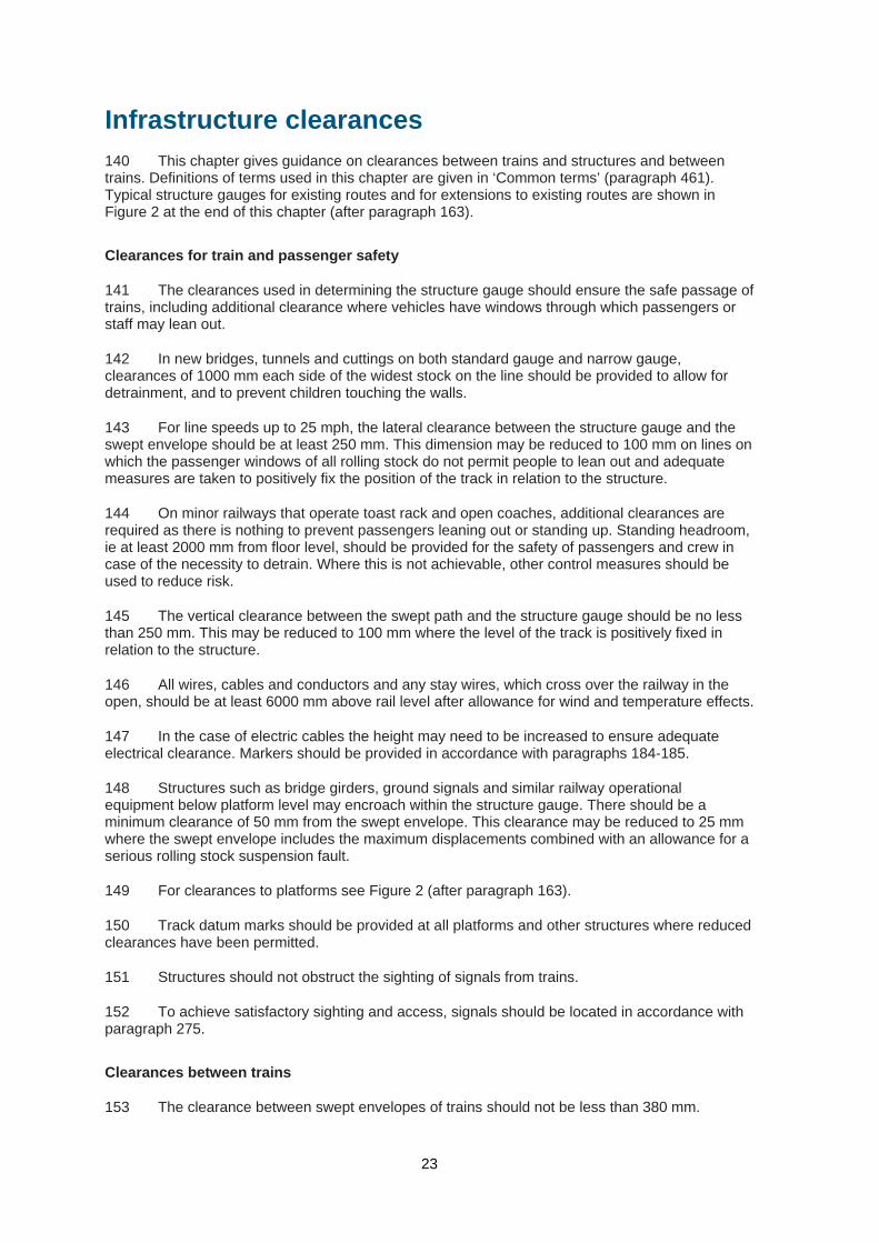
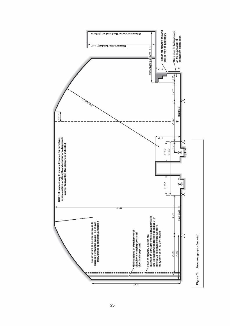
18 Minor railways may vary from simple straight lines or loops, laid on private land and operated on the ‘one-engine-in-steam’ principle, to complex layouts with interlocked points and signals, track circuits and block instruments. The gauge of such lines generally ranges from 15 in (381 mm) to standard gauge, sometimes operating over relatively long distances in rugged terrain.
19 Minor railways may be constructed and operated under statutory powers. Statutory authority is likely to be necessary if the railway crosses the public highway at any level, or where it could secure immunity from nuisance claims (for example because of the generation of noise or smoke). In the past, such authority took the form of a private Act of Parliament or a Light Railway Order. Since 1993 authority for lines in England or Wales has been obtained through an order issued by the Secretary of State for Transport under the Transport and Works Act 1992.
7 The
Transport and Works (Scotland) Act 2007 18 received Royal Assent on 14 March 2007 and provides for similar orders in Scotland.
20 HMRI is the enforcing authority for all lines (whether authorised by statute orotherwise), acting either directly or on behalf of the Secretary of State for Transport, and imposes certain constraints on minor railways regarding speed and weight limits.
21 Minor railways may be operated by paid staff, by volunteers, or by a mixture of the two. In this document, the term ‘staff’ includes both paid staff and volunteers.
Objective and scope
22 The guidance for minor railways provided in this document is recommended by HMRI. It supports and amplifies all the principles set out in Part 1 of the RSPG. HMRI has prepared this guidance for two purposes:
(a) to highlight and expand, as necessary, those chapters in other sections of the mainline railway RSPG Part 2 guidance which are particularly relevant to those proposing to establish and operate a minor railway; and
(b) to acknowledge those aspects of the RSPG relating to minor railways that can be relaxed in view of the slow speeds etc of the trains and those aspects to which special attention should be paid.
23 Some railways have works, plant or equipment (including locomotives and rolling stock) which do not meet the terms of the RSPG in all respects. Where these have been in use over a sustained period with suitable operating practices and staff training, these arrangements may remain in place so long as the works, plant or equipment continue to be used with these safeguards and the arrangements comply with the railway’s safety case or safety case exemption submission.
24 Where there is an intention to introduce, for the sake of historical accuracy, equipment or practices that do not meet current safety standards, HMRI should be consulted before any changes are made.
10
25 Those intending to construct or establish a minor railway should seek expert advice in all matters of track construction, maintenance and operations. Membership of the Heritage Railway Association (HRA) is recommended as this is the recognised body representing minor and historical railways, lines of local interest and railway museums with the railway industry, national and local tourist boards, trade and national and regional government, including HMRI. The HRA provides guidance for its members on issues such as Safety Management Systems and Safety Critical Work. It is also able to offer advice and assist with locating suitable consultants. See ‘Useful links’ for the HRA’s contact details.
26 Where changes are proposed to works, plant or equipment already in use, the changes should be in accordance with this guidance, where this is reasonably practicable, rather than complying with earlier standards under which the existing works, plant or equipment were originally approved.
Compatibility
27 Approval under the Railways and Other Transport Systems (Approval of Works, Plant and Equipment) Regulations 1994
3 often depends upon a clear demonstration that the new or altered
works do not adversely affect the safety of any existing:
(a) infrastructure;
(b) rolling stock; or
(c) operational procedures;
through the introduction of:
(a) incompatibility; or
(b) inconsistency.
28 Whenever additions or changes are proposed to any features of a railway, particular consideration should be given to all the interfaces affected. The whole railway should be regarded as a single system where each:
(a) component;
(b) engineering discipline;
(c) operating rule and procedure;
forms part of the whole, and all are interdependent. These matters are referred to among those listed under principle 1 of RSPG (Part 1).
29 Examples of interfaces requiring consideration include:
(a) wheel profiles in relation to rail profiles;
(b) clearances to adjacent structures and other railway lines;
(c) axle loading with respect to track and bridges.
30 The three interfaces referred to in paragraph 29 are of particular concern when exchanges of locomotives and rolling stock take place between minor railways or between a minor railway and the national network. Other examples are:
(a) compatibility of permitted wear for wheel tyres and for permanent way points and crossings;
11
(b) adequate sighting from every driving cab and footplate; and
(c) suitable construction of and procedures for the operation of any level crossing.
31 This listing is not exhaustive because any modification or addition to the railway could possibly have consequences for procedures or for other equipment on or adjacent to the railway.
32 The commissioning of new works, plant or equipment may introduce incompatibilities or inconsistencies with existing works, plant or equipment. This could have implications for safety. In this case, approval of the new works, plant or equipment may only be given if appropriate modifications are also made to the existing facilities.
Terminology
33 Throughout the document the words listed below are used with the following specific meanings:
(a) should - the primary verb for statements of guidance;
(b) may - where the guidance suggests options;
(c) must - only used where there is a legal requirement for the measures described to be employed. A reference to the relevant act or regulations will be provided;
(d) is (are) required - having decided upon a particular option or arrangement, some consequential choices stem from that first decision. This expression is used to indicate those consequential choices and where firmer guidance is considered appropriate.
34 There is also a section on ‘Common terms’ at the back of the book (see paragraph 461).
Note 1: Any reference in this guidance to any material or article complying with a specific standard should be satisfied by
compliance with any relevant standard recognised in any member state of the European Community, providing that the
standard in question offers guarantees of safety, suitability and fitness for purpose equivalent to those offered by the
standard referred to in this guidance.
Note 2: Throughout this document both imperial and metric measurements are used. In some instances imperial
measurements are used alone where this reflects the materials and historic practices of minor railways and to use a metric
conversion would cause confusion.
For reference
1 inch = 25.4mm
1 foot = 304.8mm
1 yard = 914.4mm
1 mile per hour = 1.61km per hour
1lb = .45kg
12
The track 35 The track supports and guides the trains. It may consist of a ballasted track, a rigid formation or a special structure. Other track forms may be approved in discussion with HMRI. Additional and comprehensive guidance can be found in publications by The Permanent Way Institution (see ‘Useful links’) and the Civil Engineering Conference.
36 The permanent way should be designed, installed and maintained to a standard suitable for the axle loads, tonnage and speeds of the traffic it has to carry.
37 Adequate measures should be taken to ensure the stability, line and level of the track under all conditions of applied load plus temperature-generated stresses by giving due consideration to the design of formation and all track components.
38 The formation should be designed to provide adequate support to the track. Cross-falls and drainage should be provided as required. On weak or unstable ground, additional measures may be required to ensure stability.
39 The type, quality and depth of ballast, where provided, should be related to the loading and the nature of the formation (see section on ballast below).
40 Precautions may be required to minimise vibration in adjacent buildings, particularly if the track is supported on concrete or other solid foundation.
41 Noise created by railway traffic should be kept to a minimum.
42 Track should be designed to accommodate the mechanical requirements of the signalling system, such as point rodding, facing point locks and treadles. See Chapter 9 (paragraphs 237-328).
43 The track should be inspected and patrolled frequently. This is particularly important where vandalism is a problem. The degree of inspection depends on the circumstances, for example on a rural line the first train of each day would proceed under caution and foot patrols might be weekly, but in areas prone to vandalism daily inspections on foot may be necessary.
44 The railway should maintain a directory of known hazards, such as overhead power cables and buried services, and other important information relating to access arrangements including access points and sections where access is prohibited while trains are running.
Ballast
45 The object of ballast is to provide resilient support and to prevent movement of the track and to promote drainage of water from it. In the UK the best and most expensive ballast is crushed granite but other common materials, in descending order of utility, include crushed slag, crushed limestone, crushed flints, gravel, beach shingle, ash and sand. Typically, the hard stones are crushed to 40-65 mm cube for standard gauge railways and 25-44 mm cube for narrow gauge railways. Consider the proposed traffic: light vehicles providing a seaside ride at 10 mph require a much less perfect road than a 15 in steam 4-6-2 hauling a heavily loaded passenger train at 25 mph.
46 For standard gauge railways there should be a depth of ballast no less than 150 mm (ideally 225 mm) below the sleepers on jointed track and ballast shoulders (ideally 380 mm wide) should be provided to ensure the stability of the track, particularly in curves. For narrow gauge railways on jointed track, the ballast depth should be a minimum of 75 mm (ideally 150mm), with a ballast shoulder width of 100 mm.
47 On certain soils it may be necessary to provide a permeable ‘blanket’ of sand above the subgrade in order to prevent clay or mud being pumped up into the ballast, or an impermeable

13
sheet of suitable material between the bed and the ballast to stop excessive water reaching a poor subgrade.
48 Some railways in mountainous areas may be built on the rock, particularly in cuttings or on ledges, and a depth of ballast greater than the minimum referred to in paragraph 46 may be required if hard spots are to be avoided.
49 The ballast should be maintained regularly to prevent lineside vegetation encroaching and disturbance by animals. The cesses should be kept clear to assist drainage and to provide a safe walking route for maintenance staff.
Sleepers
50 Sleepers should be located securely in good ballast to prevent movement and avoid strained or dipped rail joints.
51 Sleepers may be made of wood, concrete or steel.
Note 1: Softwood sleepers will need to be treated against rotting. Wooden sleepers are resilient and thus tend to give a
smooth ride.
Note 2: Reinforced concrete sleepers are resistant to rot and rust. If used, they should be inspected periodically, particularly
for damage causing the reinforcing rods to be exposed. Minor derailment may cause irreparable damage. Care should be
exercised in the selection of second-hand concrete sleepers to ensure that the housings are not loose and reinforcing rods
are not exposed.
Note 3: Steel sleepers are susceptible to deformation resulting from minor derailment but can hold the alignment well and
offer benefits with respect to manual handling risks for staff.
52 Where an unconventional form of track construction is proposed, the company should seek the advice of HMRI.
Rails
Running rails
53 Running rails should comply with the appropriate British or European Standard or an equivalent standard acceptable to HMRI and have a consistent head inclination on the system.
54 The use of rail joints should be minimised, particularly in inaccessible places, such as level crossings and bridges.
55 Where it is necessary to cut rail intended for re-use this should be done using an appropriate saw and not a gas torch. Similarly, bolt-holes should not be cut using a gas torch.
14
56 The weight of rail to be used should be appropriate for the maximum weight (ie axle loading) and the speed of the trains prescribed in the approval or any subsequent direction issued by HMRI. If a mixture of locomotive types and rolling stock is used, the track should be suited to the longest and heaviest stock. Experience has shown the following weights of rail to be suitable for light railways operating at a maximum of 25 mph.
Weight of rail in lbs/yard
Axle loading in tonnes
30 4 to 6
35 5 to 7
40 6 to 8
45 7 to 9
50 8 to 10
55 9 to 11
60 11 to 13
65 13 to 15
70 15 to 17
Figure 1: Suitable rail weights for light railways
Note 1: The determining factor in the selection of rail will often be dictated by the locomotives that are to be operated, with
axle loadings ranging from 7 tons for a small tank engine to 23 tonnes for a large Pacific locomotive. Flat bottom rail to BS
113A or bull head rail to BS 95R (both defined in BS 11 Specification for railway rails 8) is suitable for axle loadings of up to
25 tonnes.
Note 2: For standard gauge track it is usual to provide 24 sleepers per 60 ft rail length, the sleepers nearest to the joints
being spaced at 600 mm (2 ft apart).
57 Rails should be as long as practicable and permanent closure rails should be at least 4500 mm long for standard gauge and 3000 mm long for narrow gauge. Shorter closure rails may be permitted under special circumstances but these should have the agreement of HMRI.
58 Fastenings should comply with the relevant British or European Standards or an equivalent standard acceptable to HMRI. For narrow gauge railways agreement should be reached with HMRI where the railway is new or the fastenings are of a type not previously used on that railway.
59 Tie bars used to maintain gauge should not be used as a permanent solution, nor should they be used in points and crossings. Ideally, they should not remain in situ for more than six months and while in situ they require regular inspection and maintenance. Best practice is to use a minimum of three tie bars to distribute the load.
Check rails
60 Check rails should be provided on curves of small radius where long, rigid-wheel-base vehicles are used.
Note: For example, on standard gauge track, if the rigid wheel base exceeds 3000 mm, check rails should normally be
provided on curves having a radius of 200 m (10 chains) or less.
15
61 The bearing edge of a check rail should be placed at a distance from the running edge of the high (outer) rail, equal to the distance between the backs of a pair of wheels plus the effective thickness of one flange; any gauge-widening on the curve should be added to the flangeway.
Cant
62 The application of cant should only be considered after consultation with a person competent in permanent way matters. The ongoing maintenance of canted track is particularly important to avoid the possibility of track twist.
Radii of curves
63 Curves with largest-possible radii should be provided, since reduced radii results in increased rail and flange wear and increases the risk of derailment. Reduced radii also reduce the weight of train a locomotive is capable of hauling. The minimum acceptable radius of curved track varies with the type of stock used and the speed at which it is operated. As a general guide, the minimum radius curve should be at least 20 times the maximum fixed wheelbase of rolling stock using the line.
Fishplates
64 Fishplates should have at least four bolts, be of the correct profile to match the rail and be shimmed in order to eliminate dipped joints.
Note: The use of a 1 m straight edge placed across the joint on the head of the rail will facilitate the determination of shim
thickness.
65 Fishplates should be well oiled to facilitate rail expansion without buckling the rails. Where possible, fishplate bolts and nuts should resist vibration, and should not be over-tightened, which would prevent rail expansion or contraction. Fishplates and their fastenings should be inspected regularly.
Rail fastenings
66 Rail fastenings include plain and elastic spikes, coach screws (‘chair screws’), nuts and bolts, chairs, spring clips, keys and baseplates.
67 Dogspikes may be used with flat-bottomed rail on wooden sleepers, but should be regularly inspected to ensure they are not becoming loose.
68 Chair screws are used in conjunction with chairs, certain types of baseplate and stepped clips or washers on wooden sleepers. On light rails for narrow gauge, they may be applied directly to the rail foot.
69 Chairs are used in conjunction with bullhead rail. They may be secured to the sleeper with chair screws, through bolts or trenails and spikes, although the latter method is now obsolete. On concrete sleepers, a felt or rubber pad should be used between the chair and the sleeper. Wooden or steel keys are required to secure the rail to the chair.
Turnouts or points
70 Unless point blades are fully closed against the stock rail, there is a risk of derailment. Facing point locks should normally be provided on passenger lines with a track gauge of 15 in (381 mm) or greater. Facing points on a passenger carrying running line of a railway should be kept to a minimum (see also paragraphs 248-253).
71 Some existing railways use spring-loaded points or weighted levers at run-round and passing loops. They enable the train to run into a station, the locomotive to be detached and run round the train, without the need for staff to be available to switch the points. There should be a

16
means of clearly establishing that the point blade is fully closed, eg by providing target discs behind the weighted levers, so that drivers can see more easily that the weights, and therefore the blades, are fully home.
Note: There is a risk with this type that the blades might not be fully closed, perhaps due to vandalism, say from children
putting stones in the track, or to wear of the components. The driver is responsible for seeing that they are safely set in the
correct direction when he approaches them, which may require a speed restriction.
72 Hand-operated point switches for non-passenger lines may be driven by a spring-loaded toggle mechanism.
73 Flexible, long-bladed points are preferred for passenger operation. Industrial or tramway-type stub or hinged blades should not be used for passenger railways as they can give large turning forces with the attendant risk of derailment.
74 The appropriate number of stretcher bars and drives should be installed on all points.
75 Clearances of flangeways and crossings should be compatible with the profile of the wheel flanges.
76 Fouling point markers in loops and sidings are useful in assisting staff involved in the movement of trains. The markers themselves should not present a tripping hazard.
Trap points
77 Where sidings or goods lines converge on passenger lines, and any overrun from such lines might foul a passenger line, trap points or derailers should be provided to derail overrunning vehicles away from the passenger lines, structures and any other hazards.
Catch points
78 Wherever loose coupled operations are undertaken, catch points should be provided to derail vehicles running away backwards, located so that vehicles are not directed toward another line or another hazard.
Turntables
79 Turntables should be capable of accommodating the longest rolling stock used on the railway, be adequately lit during hours of darkness or poor visibility and have suitable protection for pedestrians.
80 Turntables should be located on level ground and at a distance from adjacent lines that provides safe clearances for staff.
81 Where it is possible to leave the turntable directly onto the running line the turntable bolt should be interlocked with the signals.
Note: It is important to consider the compatibility of visiting locomotives and rolling stock with the design and operation of the
turntable.
Lineside structures and equipment
82 Lineside structures and equipment should be designed and located so that they can be reached, and planned maintenance carried out, without danger from trains. Safety barriers may be required between equipment and the adjacent track where there is a danger of staff moving to a place where they are at risk of being struck by trains.

17
83 Signal posts and their telephones, and other individual structures or items of fixed equipment not exceeding 2000 mm in length, should not be positioned so as to obstruct a lineside path. Where there is insufficient space to safely position the path between the track and the structure, the path should pass behind that structure.
84 Lineside equipment and structures to which staff may need to gain access while trains are running should be located at a safe distance from passing trains. Where possible, access doors into lineside equipment should not open towards passing trains.
85 The positioning of lineside equipment should not adversely affect signal sighting.
86 Signal posts and their telephones should not be less than 570 mm from the swept envelope of trains.
87 Where train crew may regularly require to gain access to the track, for example to use signalpost telephones, provision should be made for their safety (including suitable hard standing).
Lineside paths and places of safety
88 Every effort should be made to avoid the need to access the track while trains are running.
89 Where access to the track is required when the line is open to train movements, a lineside path should be provided on one side of the track for staff to walk on. It should be a minimum of 700mm wide and clear of the swept envelope for rolling stock operated on the line. Such paths should be kept clear of obstructions.
90 Where cable troughing routes form part of any walkway they should be designed so that they do not introduce additional hazards and should have suitably secure lids.
91 Where a walking route cannot be made continuous or crosses any track, appropriate provision should be made.
92 The crossing point between places of safety should be located where adequate sighting is available. If adequate sighting is not available at the crossing point, a suitable means to warn of the approach of trains should be provided (eg white lights activated by train approach). The location of all authorised crossing points should be suitably identified.
93 On existing railways where it is not reasonably practicable to provide a lineside path, a continuous place of safety not less than 400 mm wide should be provided. Clearances to a place of safety from the track are given in paragraph 160.
94 At any place from which the approach of trains cannot be seen in sufficient time for staff to stop work and reach a place of safety, work should not be undertaken while trains are running.
Signing of restricted clearances
95 Where the lateral clearances specified in paragraph 160 are not available, carrying out a risk assessment and implementing a safe system of work may make it possible for staff on the line to undertake their duties safely. ‘Limited Clearance’ warning signs should be fixed at about eye level at each end of the restriction.
96 Where the required lateral clearances are not available for a distance of more than 40 m, staff should be excluded from the area while trains are running and a prohibition sign should be erected at each end of the structure.
97 Where clearances are adequate on one side of the line but not on the other, a prohibition sign should be provided on the restricted side in place of the ‘Limited Clearance’ sign.
18
98 Where staff are not permitted on the track when trains are running, prohibition signs should be provided at both ends of such sections and at any potential access points including the ends of all platforms.
Between lines
99 Where a place of safety is between two running lines or between a running line and a siding, its width should be 900 mm to allow for the possible effects of staff disorientation.
100 The distance between tracks should be no less than the 900 mm place of safety plus the appropriate clearances for the swept envelope for each adjacent track.
101 Where the clearances from adjacent lines are different, the position of the place of safety should be clearly marked.
102 In sidings where the only work carried out involves side access for entry or for simple tasks such as examination of rolling stock, train preparation or coupling of vehicles, the total clearance between adjacent static envelopes may be reduced to 830 mm.
103 Where maintenance is required to be carried out, or a through authorised access route is required, the interval should be increased sufficiently to ensure that staff can remain in a place of safety clear of both tracks.

19
Earthworks, embankments and cuttings 104 Embankments should be constructed using suitable materials to provide adequate support to the formation and long-term stability.
105 Cutting slopes should be suitably graded to ensure long-term stability. In steep-sided cuttings precautions should be taken to prevent materials falling onto the line.
106 Protection should be provided to prevent the toes of embankments and cuttings being scoured or eroded.
107 Appropriate measures should be taken to prevent erosion of embankments, cutting slopes and the track formation during strong water flows. Particular attention should be paid to susceptible locations such as bridges over cuttings and transitions between cuttings and embankments.
108 Adequate arrangements should be made to intercept and direct any cross flow of ground or surface water that may be affected by any railway works.
109 Water drainage provisions should conform with the requirements of all relevant statutory authorities.
110 Retaining walls should be designed to ensure long-term stability. Where there is a steep or vertical drop and staff are required to gain access to the top of the wall on a regular basis, a handrail or parapet should be provided.
111 The effect of burrowing animals on the stability of earthworks and embankments should be considered.
20
Bridges, viaducts and tunnels 112 This chapter provides guidance on bridges, viaducts, tunnels and similar structures.
Note: In the following paragraphs bridges include viaducts.
113 Bridges should be durable and provide for ease of inspection and maintenance. Inspection and assessment should be carried out by a competent engineer who should advise on the condition of the structure and the appropriate maintenance arrangements.
114 Consideration should be given to the safety of railway staff and others, including those carrying out inspection and maintenance.
115 Adequate arrangements should be made to drain water from bridges and other structures on the railway.
Bridges and viaducts carrying the railway (underline bridges)
116 The design criteria to be applied to new or reconstructed bridges carrying the railway, together with the associated design loads and specification of materials and workmanship, should be in accordance with the appropriate British and European Standards, Codes of Practice and the requirements of the relevant authority.
117 The headroom over public roads beneath newly constructed railway bridges should be at least 5300 mm. It should be maintained thereafter to not less than 5030 mm and should be provided over the full width of the carriageway including hard shoulders etc.
118 The headroom provided when a bridge is reconstructed should not be reduced, and where practicable should be increased to or towards 5300 mm. For new railway bridges over high load routes, the headroom should be increased in accordance with applicable Department for Transport (DfT) standards.
119 Where the headroom over a road is unavoidably less than 5030 mm, prescribed ‘Low Bridge’ signs should be displayed at the bridge and on its approaches in accordance with the Traffic Signs Regulations and General Directions 2002.
9 Further protective measures may be
necessary in accordance with DfT guidelines. In such cases the relevant highway or roads authority and HMRI should be consulted.
Derailment containment
120 The design of a bridge carrying the railway should consider the possible effects of a train being derailed on it, or on the immediate approaches to it. Similar consideration should be given to embankments where any part of the height is formed of a vertical or near vertical face.
121 Suitable means to contain the wheels of derailed vehicles should be provided. Robust kerbs are considered to be a suitable means of containment.
Note: On minor railways, check- or guard-rails may be an adequate means of derailment prevention/containment.
122 Derailment protection measures should extend clear of the bridge on the approach side for approximately 1500 mm where reasonably practicable.
Protection of piers
123 Bridge supports may require protective measures to avoid damage by road or rail vehicles. Where the railway crosses a waterway, measures may be necessary to protect the bridge from damage by vessels and from the effects of scour.
21
Parapets
124 Bridges should incorporate a safe lineside walkway with a substantial parapet or railings no less than 1250 mm above the walkway. Where railings are provided the lowest 150 mm should have a solid in-fill. Horizontal clearances to the walkway and parapet should be in accordance with Chapter 2 (paragraphs 88-103) and Chapter 5 (paragraphs 140-63). Walkways on top of longitudinal girders, above track level, should have adequate access from the track at each end and at any intermediate points to comply with paragraphs 89-98.
125 Bridges or viaducts near stations or ‘Stop’ signals on the approach to stations, where a passenger might inadvertently alight onto a girder or parapet, may require a fence above the parapet, unless the structure itself provides protection. Signs warning passengers not to alight may be necessary.
Bridges and viaducts over the railway (overline bridges)
126 The supports of structures built over the railway lines may need to be protected from the consequences of being struck by derailed railway vehicles. Supports should be located as far from the railway tracks as practicable and be designed to minimise the effects of contact by a derailed vehicle. Unless they can be located at least 4500 mm from the nearest rail, the supports should be designed to withstand notional impact forces. Such protection should be considered at an early stage since it may influence both the type of structure chosen and the location and type of its supports.
127 Bridges should be designed to deter people from climbing along the structure, climbing onto and along the top of any parapet, and dropping and throwing objects on the railway.
Parapets
128 The parapets of road bridges should have the strength, containment and design characteristics specified by DfT or another relevant authority. An equivalent standard of protection may be provided on the approach to the bridge and parapets.
129 For bridges carrying all-purpose roads and for footbridges, a parapet with a traffic face that is imperforate, smooth and without hand or footholds should be provided. The minimum height of the parapet above the adjoining paved surface should be maintained at no less than 1500 mm. For bridges used frequently by equestrian traffic, the parapet height should be no less than 1800 mm.
130 Where vandalism may be a problem, parapets at least 1800 mm high or a totally enclosed structure may be necessary.
131 All coping stones and components attached to the parapet should be adequately secured to deter removal.
132 On all new bridges that have parapets with a thickness over 100 mm, the top of the parapet should be finished to deter climbing and walking.
133 On bridges carrying roads from which pedestrians, animals, pedal cycles and vehicles drawn by animals are excluded by Order, the minimum height of the parapet above the adjoining paved surface may be reduced to 1250 mm. The lower 600 mm of the parapet should be provided with a mesh or solid in-fill panel, which may be mounted outside the longitudinal members of the parapet.
134 ‘High containment’ parapets should be provided where the likelihood of impact with the parapet and consequential damage outweigh the hazards resulting from the containment and redirection of errant road vehicles within the traffic stream. Parapets should be designed so that any foreseeable vehicle impact cannot dislodge any part of the structure onto the railway.
22
135 In the event of disagreement between highway and railway operator about the need for high containment parapets, the matter should be referred to HMRI for resolution.
Pipe bridges
136 Pipelines carrying liquids or gases over the railway, where the pipes are not incorporated in a bridge structure, should be supported by a purpose-designed beam or service bridge. Such a bridge should span the railway without intermediate supports. Where supports are necessary, they should comply with paragraph 126.
137 Appropriate measures should be taken to deter trespass onto pipe bridges.
138 Adequate measures should be taken to contain and limit the extent of any spillage of hazardous substances from pipe bridges and to direct them away from the railway.
Note: In the case of low-pressure water mains or similar pipes conveying non-hazardous materials, and where significant
savings in cost would result, consideration may be given to a free-standing design, subject to agreement by HMRI.
Tunnels
139 If alterations are to be made to an existing tunnel or a new tunnel is to be bored, reference should be made to the RSPG Part 2, Section A (Guidance on the infrastructure)
2 and the proposals
discussed with HMRI.
23
Infrastructure clearances 140 This chapter gives guidance on clearances between trains and structures and between trains. Definitions of terms used in this chapter are given in ‘Common terms’ (paragraph 461). Typical structure gauges for existing routes and for extensions to existing routes are shown in Figure 2 at the end of this chapter (after paragraph 163).
Clearances for train and passenger safety
141 The clearances used in determining the structure gauge should ensure the safe passage of trains, including additional clearance where vehicles have windows through which passengers or staff may lean out.
142 In new bridges, tunnels and cuttings on both standard gauge and narrow gauge, clearances of 1000 mm each side of the widest stock on the line should be provided to allow for detrainment, and to prevent children touching the walls.
143 For line speeds up to 25 mph, the lateral clearance between the structure gauge and the swept envelope should be at least 250 mm. This dimension may be reduced to 100 mm on lines on which the passenger windows of all rolling stock do not permit people to lean out and adequate measures are taken to positively fix the position of the track in relation to the structure.
144 On minor railways that operate toast rack and open coaches, additional clearances are required as there is nothing to prevent passengers leaning out or standing up. Standing headroom, ie at least 2000 mm from floor level, should be provided for the safety of passengers and crew in case of the necessity to detrain. Where this is not achievable, other control measures should be used to reduce risk.
145 The vertical clearance between the swept path and the structure gauge should be no less than 250 mm. This may be reduced to 100 mm where the level of the track is positively fixed in relation to the structure.
146 All wires, cables and conductors and any stay wires, which cross over the railway in the open, should be at least 6000 mm above rail level after allowance for wind and temperature effects.
147 In the case of electric cables the height may need to be increased to ensure adequate electrical clearance. Markers should be provided in accordance with paragraphs 184-185.
148 Structures such as bridge girders, ground signals and similar railway operational equipment below platform level may encroach within the structure gauge. There should be a minimum clearance of 50 mm from the swept envelope. This clearance may be reduced to 25 mm where the swept envelope includes the maximum displacements combined with an allowance for a serious rolling stock suspension fault.
149 For clearances to platforms see Figure 2 (after paragraph 163).
150 Track datum marks should be provided at all platforms and other structures where reduced clearances have been permitted.
151 Structures should not obstruct the sighting of signals from trains.
152 To achieve satisfactory sighting and access, signals should be located in accordance with paragraph 275.
Clearances between trains
153 The clearance between swept envelopes of trains should not be less than 380 mm.

24
154 When existing railways are reconstructed or altered, the 380 mm clearance should be provided wherever this can be achieved. Where this cannot be achieved in full, the maximum clearance practicable should be provided, but the clearance should not be less than 100 mm.
155 Where there are more than two running lines or there are sidings adjacent to running lines, wider intervals between pairs of running lines and between running lines and sidings may be necessary to ensure the safety of trains and staff. See paragraphs 99-103.
Clearances required for staff safety
156 Where staff are permitted to be on or near the railway tracks while trains are running, additional clearances to those required for train and passenger safety are required.
157 Clearances should be such that there is room for staff working on the line to move to a position of safety.
158 The requirements for staff safety given in this chapter should be applied whenever the work sallow them, or operational changes necessitate them, such as when:
(a) new structures are built, or existing ones are reconstructed;
(b) any line speed increase is introduced which makes the warning time available to staff too short;
(c) alterations to the track layout or signalling are carried out which introduce, or increase the extent of, bi-directional running; or
(d) additional tracks are laid or realignment results in significant changes in clearances.
159 Details of lineside paths and places of safety for staff working on or near to the track are given in paragraphs 88-103.
160 The minimum distance between the swept envelope of a train and a lineside path or place of safety should be 430 mm.
161 On existing railways, at places where clearances are less than those specified in this guidance, the present clearances should not be reduced, nor should the length or number of such places be increased by new or altered works, by track alterations affecting line or level, or by the introduction of different rolling stock, without the agreement of HMRI.
Typical structure gauge
162 The typical structure gauge for existing routes and for extensions to existing routes is shown in Figure 2 at the end of this section.
163 The structure gauge derived from the above considerations should be used to determine dimensions from a fixed datum, preferably the running face of the nearest running rail.
Note 1: The clearances to be used in determining the structure gauge should ensure the safe passage of trains including
additional clearance where rolling stock have windows through which passengers or staff may lean out.
Note 2: The dimensions shown in Figure 2 are for vehicles with a kinematic envelope not exceeding 3020 mm width (2820
mm static vehicle profile running on standard gauge (nominal 1435 mm) lines on straight level track). They should be
increased to allow for curvature and super-elevation of the track.
Note 3: Permissible infringements above rail level for conductor rail equipment, guard and check rails, trainstops and
structures in the space adjacent to and between the tracks are not shown (see paragraph 146).
25 25
26

27
Infrastructure access control 164 This chapter gives guidance on the fencing of railways and the means of providing and controlling access to the railway.
165 Regulation 3 of the Railway Safety (Miscellaneous Provisions) Regulations 199710 places a statutory duty upon the infrastructure controller to ensure, so far as is reasonably practicable, ‘where and to the extent necessary for safety, that unauthorised access to that infrastructure is prevented’. It relates to entry by trespassers, and also by large animals that might damage or derail a train and endanger passengers. At locations where some form of fencing is necessary, the type of fencing to be provided should take into account the speed of trains, any electrification, population density, and any history of trespass and vandalism.
Fencing
166 Where necessary, fencing should be continuous, clearly visible and of sturdy construction although natural growth, ditches or mounds may provide suitable barriers in certain locations.
167 Minor railways are frequently equipped with fences, walls, hedges and other barriers constructed to earlier standards. Provided that they are in good repair and risk assessment shows them to be appropriate to the current risks at the location, they may remain in use. If these conditions no longer apply, a more suitable replacement should be installed.
168 Additional fencing may be required at public footpaths, bridleway, vehicular and other crossings of the line. See RSPG Part 2, Section E Guidance on level crossings.
169 In built-up areas, welded mesh or chain-link fencing may be necessary. Additional means to deter climbing should be provided in areas where a particular trespass problem exists.
Note: Although these measures may appear onerous for a minor railway, in densely populated areas subject to extreme
vandalism young children may be endangered by access through damaged fences.
170 In rural areas, consideration should be given to the prevention of large animals straying upon the railway.
171 Pay special attention to structures, other fences etc that either abut or are close to the lineside fence and which may provide a possible means of climbing over or avoiding the fence.
Access to the railway
Maintenance access on foot
172 Gates in the railway boundary fence should be kept locked. The locks, bolts, gate hinges and any warning notices should not provide footholds. It is useful to keep records of the access points along with Ordnance Survey grid references for these locations.
173 Where regular access to the lineside is required, it should be along defined access routes. If steps and ramps lead directly to the lineside path, suitable level hard standing should be provided at both ends of the steps and ramps. A barrier may be necessary at the end of the access to the trackside or lineside walkway, to prevent accidental access onto the tracks.
174 The needs of emergency services to gain access to the line should be catered for, particularly at tunnels, bridges and viaducts, and procedures should be practised during occasional emergency exercises.
28
Maintenance access for road vehicles
175 Suitable access should be provided for road vehicles involved in maintaining railway infrastructure, carrying permanent way materials, signalling equipment etc. This should be by a lockable gate located at the boundary of the railway lands. A suitable area should be provided at the end of the access routes for parking and turning.
176 Where access routes approach the line, suitable barriers should be provided to prevent road vehicles accidentally overrunning onto the track.
Adjacent highways
177 The Highway Authority should be consulted and their agreement sought for any proposals that affect the adjacent highway.
178 Where the lights from road vehicles or other roadway lighting may interfere with a train driver’s view of railway signals, anti-dazzle fencing or other screening should be provided.
179 Where a roadway runs alongside or converges on a railway at such a distance and level that a runaway vehicle could obstruct the railway, a means of containing the vehicle before it reaches the railway should be provided.
Note: The form of the barrier will depend on the type of road traffic and speed and topographical features. It may consist of
tensioned or untensioned steel beams, ditches, mounds or reinforced walls. The highway authority will provide advice with
respect to the appropriate barrier design.
180 Safety fences complying with the appropriate DfT standards may be required on the road approaches to railway overline and underline bridges, especially if the road curves or is on a falling gradient.

29
Identification of the infrastructure 181 This chapter gives guidance on the locations or parts of the infrastructure that need to be readily and uniquely identified and the appropriate means of doing so.
182 Conspicuous distance markers should be maintained at suitable and regular intervals along the track.
183 Track gradient markers should be provided at all significant changes in the degree or direction of slope.
184 Lineside markers should be provided indicating the location of all power lines that cross over the railway, and giving the maximum safe working height beneath them.
185 Lineside markers should be provided indicating the location and depth of all buried power cables and other buried services that cross under or pass along the railway.
186 All bridges and other fixed structures should be uniquely identified. The identification should be conspicuous from both road and rail, as appropriate. It is important that rail over road bridges are uniquely identified and where they are of substandard height the contact telephone number of the railway should be displayed.
187 The names of junctions, level crossings and other locations, which are used as reference points by train crews and people working on or near the line, should be conspicuously displayed towards trains.
188 All track crossings, limited clearances and prohibited areas should be marked in accordance with Chapter 2 (paragraphs 82-103).
189 In tunnels, signs should be provided at suitable intervals to indicate the direction and distance to the adjacent access points or cross passageways.
190 Track datum marks should be provided in accordance with paragraph 150.
30
Stations
Station platforms
191 Paragraphs 191-207 describe measures that are applicable to all station platforms.
Platform layout
192 Stations should be constructed with straight platforms and on the level or on a gradient not steeper than 1 in 500. Minor stations at which trains do not terminate or reverse may be constructed on steeper gradients where suitable arrangements can be made to ensure safety, subject to the agreement of HMRI.
193 Station buildings and platform canopies should be located with the sighting of signals in mind.
194 Buffer stops should be provided at terminal stations or bay platforms.
195 A fixed red light should be provided at buffer stops.
Platform construction
196 Platforms should be long enough to accommodate the longest train booked to call at the station plus an allowance for inaccurate stopping, typically 2 m. Exceptionally, a shorter platform may be accepted provided that it is long enough to accommodate the majority of trains and special arrangements are agreed with HMRI for longer trains.
197 The width of any platform should be adequate for the greatest number of passengers likely to use it at any time. Platform buildings or other obstructions should not cause undue restrictions to the movement of passengers. It may be necessary to allow extra width if the platform is to be used by passengers as a route between one part of the station and another. At busy stations, barriers may be required to prevent platforms becoming overcrowded.
198 The full width should be provided over the centre third of the platform length, or longer as necessary to include any main access. Where it is not reasonably practicable to maintain a constant width of platform throughout its length it may be reduced in width at its ends to no less than the prescribed minimum.
Note: RSPG Part 2, Section B ‘Guidance on stations’ gives guidance on the construction and alteration of stations. It is
recognised that most minor railways use existing structures, which may be listed buildings. However, in planning their
operations, operators should apply the Part 2, Section B guidance so far as is reasonably practicable.
199 Platforms should be wide enough to safely accommodate the passengers using the station. Ideally, single face platforms should not be less than 2500 mm wide and island platforms should not be less than 4000 mm wide. All columns or other minor obstructions should be at least 2000 mm clear of the platform edge. Where it is intended to introduce platforms with widths below these values, the railway should discuss the matter with HMRI.
200 Platforms should have a clear headroom of at least 2500 mm to structures and platform signs for a width of at least 2000 mm from the platform edge over their whole length. This dimension may need to be increased where the floor level of any train is high relative to the platform. At distances greater than 2000 mm from the platform edge, the clear headroom to suspended equipment and signs may be reduced to 2300 mm.
201 Platforms should have a suitable passing clearance. The platform height should be determined taking into account all coaching stock using the platform.
31
202 The floor or footboards of passenger rolling stock should be as close as practicable to the platform. The vertical and horizontal distances between the platform edge and the floor or footboards of the passenger rolling stock should not exceed 250 mm and 275 mm respectively, or 350 mm on the diagonal. These dimensions should only be exceeded when dispensation has been obtained from HMRI.
203 Where appropriate, a 300 mm wide recess should be formed beneath the platform coping and this should be kept clear of cables and other obstructions to provide an emergency refuge. A wider recess may be necessary where there is a platform or other obstruction on both sides of a track.
204 All platforms should slope away from the adjacent track and have an anti-slip surface. In accordance with DfT guidance, platforms should be provided with a tactile surface to indicate the edge to visually impaired people. Platform edges (but not platform ramps) should be clearly defined with a strip of a lighter colour.
Barrow crossings
205 The railway should agree any protection arrangements with HMRI before opening a barrow crossing or other footpath level crossing within the station limits intended for passenger use.
Platform fencing
206 The back edge of platforms not otherwise protected should be fenced to a height of at least 1100 mm.
207 Protection should be provided at parts of the end of a platform where there is no ramp and at disused platforms where the track has been removed and where passengers and staff have access.
Other public areas in stations
208 The public areas of stations should allow the free movement of passengers. Platforms, passageways and stairways etc should be designed, subject to the dimensions given in this guidance, for the foreseeable peak passenger usage with due allowance for operational difficulties in emergency conditions.
209 Allowance should be made for the surge of passengers arriving by trains and for the presence and movement of passengers accompanied by children and for those with impaired mobility.
210 Changes in the width or direction of passageways that could cause constriction of passenger flow routes or congestion should be avoided. If they are unavoidable, ‘dead-ends’ should be no more than 20 m long.
211 Stations should be durable and easy to inspect and maintain. The design of stations should incorporate the need for cleaning.
212 All floors, steps, treads etc should be designed with due consideration to environmental conditions, contamination and cleaning to minimise risks of slipping and tripping.
213 All areas open to the outside environment to which people have access should have adequate means for draining water and the prevention of ‘ponding’.
214 The ceiling height in all passenger areas of stations should be no less than 2500 mm. The volume and proportion of space enclosed should be taken into account. No suspended equipment or signs should reduce headroom below 2300 mm.
215 All columns, posts, seats and other obstructions in public areas should be clearly visible in order to minimise risk to those with a visual impairment.
32
216 Stations should comply with the relevant legislation and guidance designed to create accessible buildings.
External areas and station forecourts
217 Where road access is provided, station forecourts should be designed to allow the safe passage of vehicles. Means of access should be provided for pedestrians, boarding and alighting from road vehicles, and emergency vehicles. Means of preventing accidental overrun by road vehicles onto the platforms or running lines should also be provided.
218 A rendezvous point for emergency services should be identified in a safe place. It should be in the open air and readily accessible to emergency service vehicles.
219 Consideration should be given to the means of passenger dispersal outside the station and for assembly points for evacuated staff.
220 Clear segregation should be provided between the working railway and any permanent or temporary exhibition or demonstration open to the public.
Entrances, exits and doors
221 All stations should have adequate means of escape.
222 All exit routes should be clearly signed. The exits should be designed to ensure the integrity of the means of escape and to allow the station to be evacuated safely.
223 Escape routes should lead to a place of safety capable of being used when necessary and, where reasonably practicable, outside the station premises. Where possible, exit routes should be protected from the effects of fire and smoke.
224 Doors should be avoided in all main circulation areas and passenger flow routes but may be used to control passenger flow and environmental conditions in other areas such as passenger waiting rooms, catering and shopping areas.
225 Where doors are provided, due consideration should be given to:
(a) the free flow of passengers normally and in emergency; and
(b) bi-directional flow.
226 The guidance in paragraphs 218-225 applies to modern railways, but it is recommended that, as part of their safety management system/risk assessment, minor railways draw up emergency plans for the safe evacuation of visitors and staff from stations. Such plans should be appropriate to the size of the stations and the greatest likely number of visitors (eg at special events). The plans should take into account exit routes, crowd control (particularly of children), lighting etc.
Station lighting
227 During operating hours all station premises to which passengers or staff have access during the hours of darkness should be adequately lit. Areas to which passengers have access, such as footbridges, subways, passages, stairways, steps and ramps, should be permanently lit if there is no natural light. Minor railways wishing to recreate a period lighting scheme, such as gas or oil lamps, should first discuss their proposals with HMRI.
Stairways, steps and ramps
228 This section provides general guidance for the design of stairways, steps and ramps, including those for footbridges and subways.
33
229 Stairways, steps and ramps should be of uniform and adequate width to avoid overcrowding, and should not be obstructed by any barrier. They should have anti-slip surfaces.
230 The steps of all stairways should be of uniform design complying with BS 5395.11 They should have a ‘rise’ of between 100 mm and 180 mm, with an optimum of 150 mm. The ‘going’ should be between 280 mm and 350 mm with an optimum of 300 mm. Twice the ‘rise’ plus the ‘going’ should be at least 550 mm and should not exceed 700 mm; the optimum is 600 mm.
231 Intermediate landings should be provided between flights of steps. The maximum number of steps in each flight should normally not exceed 16 but in cases of difficulty a single flight of steps with an overall rise of 3000 mm is acceptable. The length of top, intermediate and bottom landings should be at least equal to the width of the widest section of the staircase between handrails.
232 Stairways and ramps should be provided with continuous handrails on both sides, fixed at a height of not less than 850 mm, or more than 900 mm, measured vertically above the pitch line. Handrails should present a round surface between 45 mm and 50 mm in diameter for easy use by the disabled; they should extend beyond the last step or the end of a ramp, provide clear passage of the hand from end to end and be at least 50 mm clear of any obstruction.
233 Stairways and ramps should be at least 1200 mm wide between handrails to accommodate passengers with luggage. Stairways wider than 2400 mm between handrails should have a central handrail and those wider than 4800 mm two intermediate handrails. Intermediate handrails may be required on wide ramps.
234 Where a stairway, a flight of steps or a ramp leads directly towards a platform edge a barrier should be provided beyond the run-off landing if the distance to the platform edge is less than 5000 mm.
235 Ramps for passenger access should be constructed at a gradient not steeper than 1 in 20. In case of difficulty, however, and where ramps are not to be regularly used by people with mobility impairment, they may be at a slope of 1 in 12. Ramps should be provided with landings at intervals of not more than 10 m and these should be at least as long as the width of the ramp.
236 A change in direction or an offset should be provided at every second landing for ramps with a gradient no steeper than 1 in 20 and at every landing for steeper ramps.
34
Signalling systems 237 This chapter provides guidance on the main functions of a signalling system suitable for a minor railway.
238 Any railway that has more than one train in operation needs a system to prevent conflicting movements. It should be as simple as possible, commensurate with the safe operation of the railway.
239 The primary safety function of any method of working is to:
(a) prevent collision between trains;
(b) prevent derailment of trains at incorrectly set points or inadequately locked facing points;
(c) provide information to drivers regarding permitted movements and route information;
(d) control access by trains to a section of line; and
(e) protect level crossings - see RSPG Part 2, Section E Guidance on level crossings.
Note: The necessity to provide interlocking of points and signals is brought about by the requirements of regulation 5 of the
Railway Safety (Miscellaneous Provisions) Regulations 1997.10
Communications
240 Where a railway intends to use mobile phones as part of its communication system, careful consideration should be given to the risks that may arise from the use of such phones during operation and the quality and extent of coverage for the railway system.
241 Where correct and accurate communication is an essential part of the safe method of working it is important that all parties reach a clear understanding, particularly when the communication takes place over the phone or radio. Following clear and standardised communication protocols, such as the phonetic alphabet and standard terms, should assist all parties. It should always be clear to each person who exactly they are talking to and where the other person is.
Choice of signalling system
242 This section gives additional guidance on the type of signalling systems most frequently used by minor railways.
243 The majority of railways will require a signalling system. Minor railways depend almost exclusively upon mechanical signalling but the type of line, method of working and the planned speed and frequency of trains may dictate the extent of the signalling necessary.
244 With some railway operations very simple methods of working and signalling systems may be satisfactory. Where the railway operates at a low speed, typically less than 15 mph, and safety of operation can be ensured by a system of driving on sight, no signalling system may be required.
245 Train driving on ‘line-of-sight’ is only suitable for low-speed operations on simple layouts. The speed must be regulated so that the driver can stop within their sight line.
246 Those operating exclusively on the ‘one-engine-in-steam’ method of working may not require a signalling system. On lines with other operating arrangements, or which have level crossings over public carriageways, a signalling system should be provided.
35
247 It is recognised that many minor railways will wish to reproduce the signalling equipment and operating arrangements of past railway companies. This will usually consist of semaphore lineside signalling operated under the absolute block system. The guidance that follows concentrates on this type of signalling for single and double lines.
Train separation and detection
248 The guidance in this section deals primarily with the safe spacing of the permitted traffic.
249 The separation of trains should be ensured by suitable spacing. For minor railways it is appropriate to adopt fixed block sections, normally station to station.
250 Unless permissive working is allowed, or emergency working becomes necessary because of breakdown, the signalling system should not allow a train to enter a block section until that sections proved to be clear.
251 A safe train separation distance may be assured by:
(a) maintaining one or more unoccupied intervening block sections;
(b) providing an ‘overlap’ beyond the end of the block section; or
(c) by controlling the entry speed into a block section by the ‘delayed clearance’ of a signal where a full (or any) overlap is not available.
252 The number and length of the intervening block sections and overlaps should take into account:
(a) the frequency of trains;
(b) the braking performance of the trains using the line;
(c) the topography of the line;
(d) the permissible train and line speed;
(e) the type and complexity of the signalling system; and
(f) a margin for variation in the equipment or human performance.
253 Permissive block, under which more than one train is permitted into a block section, is not permitted on passenger lines.
Absolute block
254 In the absolute block system, trains are signalled from signal box to signal box. The respective signalmen are required to communicate with one another to:
(a) control the entry of trains to the section of line between them; and
(b) advise one another of the passage of trains between them.
255 In addition:
(a) a record should be kept of the passage of all trains and the exchange of train working messages in a train register book; and
(b) a means of passing emergency messages, other than by block bells, is required.
36
Note: Block instruments incorporating bells and capable of showing the status of the line, whether or not it is occupied by a
train, are a proven and acceptable method of communication between signal boxes.
256 The visual observation of the passage of trains may be assisted by providing track circuits or other train detection technology. Depending on the density of traffic and the level of risk involved, interlocking between the block instruments, any train detection system and the signals may be required.
257 The traffic capacity of an absolute block signalling system may be increased by the provision of an intermediate block (IB) section with IB ‘Stop’ signals.
258 Where semaphore signals are used in conjunction with the block system of working, ‘Stop’ signals are required to control the entry to each block section of the line.
259 A ‘Distant’ signal is desirable on the approach to the outermost ‘Stop’ signal of a block post. An unworked ‘Distant’ signal may be provided. Where such a signal is installed, it should be located at least a full service braking distance from the ‘Stop’ signal.
Note: Use of the sighting distance of the ‘Distant’ signal to provide part of the braking distance is not acceptable.
Track circuit block (TCB)
260 As its name implies, track circuit block (TCB) depends upon continuous track circuiting with signal sections between signals (or block markers) instead of block sections between signal boxes (‘blockposts’). Several track circuit block sections may be controlled from one signal box. The track circuit block system requires the block section and the overlap (which may be a complete block section depending on the type of train separation used) to be proved clear by an automatic train detection system before a train is permitted to enter the block section.
261 Because of its reliance on track circuits, TCB is not regarded as best suited to the minor railway which will find absolute block less troublesome. Infrequent operation may result in oxide deposits on the head of the rail, leading to unreliable track circuit performance.
Train detection
262 In order to operate traffic safely it is necessary to detect the location of trains and vehicles in a station or other layout. Means of achieving this range from visual observation to mechanical equipment such as fouling bars and electrical devices such as track circuits and relays.
Single line working
263 The guidance in paragraphs 263-270 is applicable to bi-directional workings on multi-track railways as well as to single line railways.
264 Particular attention is required to ensure that an appropriate level of safety is achieved to prevent conflicting movements as well as maintaining a space interval between following trains.
265 Where the single line is provided with automatic train detection, for example, it is fully track circuited (or equipped with an equivalent train detection system) and the whole of the line is within the control of one signal box. No extra safeguards over and above those provided by normal interlocking are required. Where the single line is controlled from two signal boxes and is fully track circuited, provision of interlocked directional controls is acceptable.
266 In both cases permission to enter the single line is given by the clearance of the relevant ‘Stop’ signal. The signals for entering the section should be interlocked with the train detection system to ensure the line is clear. Directional controls are to be similarly interlocked. There should be a control to ensure the signals are restored to ‘Stop’ behind each departing train and cannot be cleared again until the process is repeated.
37
267 Special consideration should be given to the positioning of signals protecting single lines to reduce the risk of driver error.
268 Precautions against signals being disregarded, which could result in trains entering the single line, may be necessary. Where a risk assessment indicates additional precautions are necessary this should be provided by directing any train overrunning a signal away from the single line. It is preferable that this should be achieved by providing alternative routes within the track layout. Only where this is not reasonably practicable should the provision of trap points be considered.
269 Where the above method of working is not available for the operation of a single line a number of alternative methods are acceptable to HMRI:
One-engine-in-steam (‘One-train-on-line’ or OTOL)
(a) With this method one train and one train only may be permitted free movement on the single line. The train-staff for the line or section should be carried on the train and no train tickets should be used. Block instruments are not necessary and signals or point indicators are not required unless needed for the protection of level crossings or to indicate that points are correctly set.
(b) Where the single line has a connection to another part of the railway system or access to the line is possible from sidings or depots, one-train-on-line may be used as an appropriate method of working, providing appropriate arrangements are made to prevent a second train from gaining access to the line.
Train-staff
(a) With this system a train-staff and a set of paper or metal train tickets are required as tokens for each section. No train may enter the single line, except for the purpose of shunting within the protection of signals, unless the train-staff for the section through which it is about to travel is at the place of departure. The train may only enter the single line with the train-staff, or the train-staff has been seen by the driver at the entry point.
(b) So long as movement through a section takes place alternately in opposite directions, the driver of each train is required to carry the train-staff as their authority. However, if two or more trains are to travel in succession through a section in the same direction the driver of each train except the last is required to be shown the train-staff and be given a train-ticket as authority to proceed. The last train of the series is required to carry the train-staff through the section before any train passes through it in the reverse direction.
(c) The train tickets are to be kept in the signal box or booking office in a locked box which can only be opened by a key forming part of the appropriate train staff. Removal of the train-staff is required to re-lock the ticket box.
(d) Divisible train-staffs have one or more detachable portions, each serving as a train ticket and so labelled. The ‘tickets’ must remain attached to the train-staff and travel with it, except when removed for issue to the drivers of the earlier trains of a series travelling through a section in the same direction, to whom the train-staff should be shown. The direction of movement through a section should not be reversed unless the train-staff and all its ‘tickets’ are at the end of the section from which the next train will start.
(e) The absolute block system, with suitable block instruments, is required to ensure a proper space interval between trains. A single line section may be divided into two or more block sections by intermediate block posts with the necessary signals, in order to increase its capacity for following movements.

38
Electric token
(a) This method employs a number of tokens, which are kept in token machines at either end of the single line. The two machines are interlocked electrically to release one token at a time to authorise movement onto the single line. The first token is required to be returned to a machine before a second token can be issued.
(b) Where signals are provided, the signals controlling entry to the single line should be interlocked with the token instruments. Auxiliary token instruments at intermediate sidings may be provided, enabling the train to be locked into the sidings, thus avoiding delay in obtaining or surrendering a token at one of the two main instruments.
Radio signalling and RETB
270 Should a railway wish to install radio signalling or radio token block, such proposals should be discussed with HMRI at an early stage.
Signals
271 The guidance in paragraphs 271-294 deals with safe routing, spacing and control of the permitted traffic.
272 Trains should only be given an indication or instruction to move off if the proposed route is safe.
273 Signals may include visual indications passed to the train crew by means of coloured lights, semaphore positions, fixed markers, coloured flags or manual display of flags or lamps.
274 The indications and meanings of lineside signals should be clear and without ambiguity. Mixing of different types of lineside signalling on the same section of line should be avoided. Particular care is required to ensure the risk of confusion is avoided where one type of lineside signalling changes to another.
Lineside signals
275 The signals should be spaced at intervals appropriate to the frequency, speed and braking performance of all trains using the line. ‘Distant’ signals located on the approach to a ‘Stop’ signal should be at a sufficient distance from the ‘Stop’ signal to allow a train to be brought to a stand at or before the ‘Stop’ signal using a normal ‘service’ brake application.
276 The layout of signals should be consistent and not likely to lead to confusion. Signals should be located so that their aspects will not be obscured, open to misreading or against a background that will make the sighting of the aspect difficult.
Note: A white backboard may be provided to aid visibility.
277 Signal aspects should be visible for an adequate length of time on the approach to the signal, and when stopped at the signal. Where an adequate sighting of a signal cannot be obtained, another signal that repeats the main signal’s aspects may be provided on the same signal post and/or on the approach to the signal.
278 Signals on the approach to junctions should give a clear indication of the route to be taken.
279 There should be full aspect (‘Running’) signals at the exit from sidings onto main lines unless a signal is provided at the limit of the shunting movement. ‘Shunting’ or ‘Subsidiary’ signals of a different appearance to ‘Running’ signals may be used for the entry to sidings or for reverse direction moves. Colour-light ‘Running’ signals controlling entry to sidings and terminal platforms,
39
where the next signal is the light on the buffer stop, should be able to show only stop or caution aspects.
280 On goods lines where permissive working is employed a separate aspect from the main ‘Proceed’ aspect(s) of the ‘Running’ signal is required for use when the section is already occupied. ‘Subsidiary’ indications at ‘Running’ signals should not be cleared as authority to pass a ‘Stop’ aspect unless it is to allow permissive working.
281 Shunting signals facing the movement in the route from a ‘Running’ signal should be capable of displaying a ‘Proceed’ aspect when the main aspect of the ‘Running’ signal is at clear. Where shunting movements are permitted along main lines, there should be a distinctive ‘Limit of Shunt’ lineside signal.
Semaphore signals
282 A semaphore signal conveys an indication by the position of the arm and its colour and shape. If the line is used during the hours of darkness or in poor visibility, a light signal that gives a corresponding indication to the semaphore arm is required. Failure of the operating mechanism of a semaphore signal should cause the arm to return to or remain in the most restrictive position and any light signal to display its most restrictive aspect.
283 On a completely signalled railway, two types of semaphore running signals are necessary:
(a) ‘Stop’ signals - a red arm with a white vertical band with light signals capable of displaying red or green aspects;
(b) ‘Distant’ signals - a yellow arm with a fishtail shaped end and a similarly shaped black band with light signals capable of displaying yellow or green aspects.
Note 1: The reverse of semaphore signals is normally white, with a black band similar to the band on the obverse.
Note 2: The colour and design of arm of semaphore signals given above has been recognised as standard for railways in
Britain.
Note 3: The signal arm should project to the left of the post.
284 For a stop signal displaying a ‘Stop’ aspect, the arm should be horizontal and a red signal light displayed. For a ‘Proceed’ aspect the arm should be moved from the horizontal sufficiently far as to avoid doubt as to the aspect being displayed.
285 For a ‘Distant’ signal displaying a ‘Caution’ aspect, the arm should be horizontal and a yellow signal light displayed. To indicate that all the related ‘Stop’ signals are displaying a ‘Proceed’ aspect, the arm of the ‘Distant’ signal should be moved from the horizontal sufficiently far as to avoid doubt as to the aspect being displayed.
286 The recommended ‘Proceed/clear’ indication is with the arm moved into the upper quadrant, and a green light after dark. Lower quadrant semaphore signals may be used if other signals on the line are of that type or if the purpose of the railway is the preservation of historical railway equipment. A mixture of upper and lower quadrant signals at one location should be avoided. Signalling of individual stations should be discussed with HMRI.
287 ‘Distant’ signals may be mounted on the same post as ‘Stop’ signals with the ‘Distant’ arm positioned lower than the ‘Stop’ arm. They should be interlocked with the ‘Stop’ signals to which they refer. The interlocking should prevent the ‘Distant’ signal being cleared unless all the related ‘Stop’ signals in advance are exhibiting a ‘Proceed’ indication.
288 Where a ‘Distant’ signal is on the same post as a ‘Stop’ signal controlled from another signal box, ‘slotting’ (an arrangement of levers and balance weights on a signal post) should prevent the ‘Distant’ signal being cleared unless both signalmen have pulled the appropriate levers and the ‘Stop’ signal is also displaying a ‘Proceed’ indication.
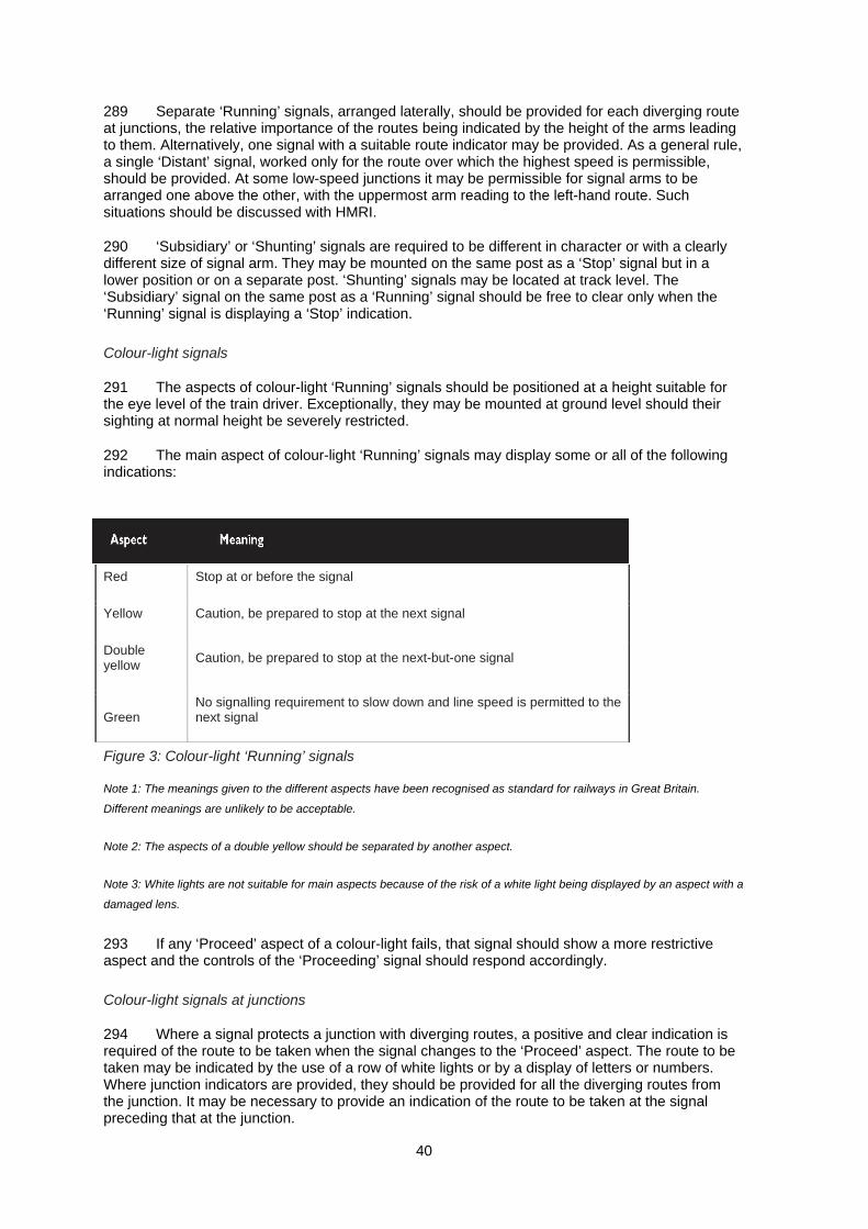
289 Separate ‘Running’ signals, arranged laterally, should be provided for each diverging route at junctions, the relative importance of the routes being indicated by the height of the arms leading to them. Alternatively, one signal with a suitable route indicator may be provided. As a general rule, a single ‘Distant’ signal, worked only for the route over which the highest speed is permissible, should be provided. At some low-speed junctions it may be permissible for signal arms to be arranged one above the other, with the uppermost arm reading to the left-hand route. Such situations should be discussed with HMRI.
290 ‘Subsidiary’ or ‘Shunting’ signals are required to be different in character or with a clearly different size of signal arm. They may be mounted on the same post as a ‘Stop’ signal but in a lower position or on a separate post. ‘Shunting’ signals may be located at track level. The ‘Subsidiary’ signal on the same post as a ‘Running’ signal should be free to clear only when the ‘Running’ signal is displaying a ‘Stop’ indication.
Colour-light signals
291 The aspects of colour-light ‘Running’ signals should be positioned at a height suitable for the eye level of the train driver. Exceptionally, they may be mounted at ground level should their sighting at normal height be severely restricted.
292 The main aspect of colour-light ‘Running’ signals may display some or all of the following indications:
Red Stop at or before the signal
Yellow Caution, be prepared to stop at the next signal
Double yellow Caution, be prepared to stop at the next-but-one signal
Green No signalling requirement to slow down and line speed is permitted to the next signal
Figure 3: Colour-light ‘Running’ signals
Note 1: The meanings given to the different aspects have been recognised as standard for railways in Great Britain.
Different meanings are unlikely to be acceptable.
Note 2: The aspects of a double yellow should be separated by another aspect.
Note 3: White lights are not suitable for main aspects because of the risk of a white light being displayed by an aspect with a
damaged lens.
293 If any ‘Proceed’ aspect of a colour-light fails, that signal should show a more restrictive aspect and the controls of the ‘Proceeding’ signal should respond accordingly.
Colour-light signals at junctions
294 Where a signal protects a junction with diverging routes, a positive and clear indication is required of the route to be taken when the signal changes to the ‘Proceed’ aspect. The route to be taken may be indicated by the use of a row of white lights or by a display of letters or numbers. Where junction indicators are provided, they should be provided for all the diverging routes from the junction. It may be necessary to provide an indication of the route to be taken at the signal preceding that at the junction.
40

41
Note 1: White lights may be used for these route indications.
Note 2: The forms of display should be appropriate to the speed of approach to the signal.
Note 3: Route indications may be required at ‘Subsidiary’ signals.
295 The display of a ‘Subsidiary’ signal should be manifestly different from that of a ‘Running’ signal.
Note 1: If white lights are used as a ‘Proceed’ aspect for ‘Subsidiary’ or ‘Shunting’ signals, it is preferable for at least two to
be required for a ‘Proceed’ aspect.
Note 2: The use of two white lights has been recognised as a standard for railways in Britain to guard against failures of a
single unproven red aspect of a ‘Shunting’ signal.
Control of signalling
296 The design of signal boxes should take human factors into account to avoid the risk of error by the signalman. The signal box should provide a working environment that minimises distraction, fatigue and stress.
Location of signal boxes
297 Signal boxes for the control of manually operated block signalling systems are required to be located adjacent to the railway with access to the line.
298 The signal box should provide for the best possible view of the signals and lines controlled. In so far as is reasonably practicable, the view should not be interrupted by the passage of trains. A signal box with its operating floor at ground level may be built only by prior agreement of HMRI.
299 The signal box name should be prominently displayed on the outside in a position visible to train crews.
Signal box facilities and equipment
300 Arrangements to prevent unauthorised access to the signalling controls and the interlocking are required.
301 The function of all signalling controls should be clearly and unambiguously indicated. Immediate and unimpeded access is required to all controls that may have to be operated to protect trains in an emergency, including replacing every ‘Stop’ signal to ‘Danger’.
302 Point rodding and signal wires are a tripping hazard. Measures should be adopted to mitigate the associated risk.
303 Where appropriate, all signalling control and interlocking systems should be protected from the consequences of electrical supply failures.
304 A means of reminding a signalman of any temporary limitations to the use of track or signals should be provided. Any such reminder, eg a lever collar, should prevent the operation of any signals or points to which it applies. The removal of the reminder should require positive action on the part of the signalman.
305 Aspects of any colour-light signal should be indicated in the controlling signal box. If the aspect of a semaphore signal is not clearly visible from the signal box an indication of the actual aspect being displayed should be provided in it. Where a ‘Distant’ signal is interlocked with a ‘Stop’ signal controlled from another signal box, indication should be given as to whether the ‘Distant’ signal is free or locked.
42
306 All indications should be clearly visible from the signalman’s normal working position. Care should be taken to avoid placing diagrams, control panels, display screens etc in a way that is likely to lead to confusion.
307 The signalman should be able to use any means of communication provided while keeping all indications clearly in view.
308 All signal boxes should be equipped with an accurate clock, flags, lamps, first-aid box, train register, table for train register, points clips and scotches, lever collars and any other provisions required to ensure compliance with the Workplace (Health, Safety and Welfare) Regulations 1992.12
309 A diagram is required showing:
(a) the lines controlled from the signal box, their identities and direction;
(b) adjacent signal boxes;
(c) all signals, points and any level crossings under the control of the signalbox;
(d) station platforms, tunnels or long viaducts; and
(e) gradients.
Note: All items on the diagram should be shown in relation to the signal box, and not give rise to confusion.
Communications between signal boxes
310 Reliable communication between adjacent signal boxes is essential for efficient and safe operation of the railway.
Communications with emergency services
311 Means of summoning the emergency services should be provided at signal boxes and control offices where appropriate.
Interlocking of points and signals
312 The guidance in paragraphs 312-328 deals with safe routing, spacing and control of the permitted traffic.
313 Interlocking is required to ensure that the signalling system can give a proceed indication only when it is safe to do so, and to maintain the route once authority to proceed has been given.
314 Point and signal controls must be so interlocked that no agency can clear a signal for the movement of a train unless the points are set and locked in the proper position. It must not be possible to clear any signals at the same time that may lead to a collision between trains.
315 Once the route has been set and locked, and the signals cleared, the interlocking must not permit any points on the route to be moved or conflicting signals to be cleared until the train has used it, or until it is known that the train will not use it. Points also should be set so as to avoid the risk of collision. The interlocking should allow a signal to display a ‘Proceed’ aspect only for so long as the conditions which allowed it to display that aspect are maintained.
316 Interlocking may be implemented by, for example, the mechanical interlocking of signal and point levers or the use of electromechanical relays. Design and construction of mechanical or relay interlocking to inherently ‘fail-safe’ criteria are required.
317 The interlocking logic should be documented in a form that can be understood by designers and railway operators, as well as signalling testing and maintenance staff.

43
Note: This may be achieved by expressing the logic conditions in a tabular form known as a ‘control table’.
318 The factors that should be taken into account in the design of the interlocking include:
(a) position (‘lie’) of points;
(b) track occupancy;
(c) overlaps;
(d) clearance points;
(e) conflicting train movements;
(f) signal aspects; and
(g) the enforced control of speed of trains at junctions, where the line speed is restricted, or on entering a terminal station.
Position of points
319 Point detection should ensure that the position of each switchblade is correct and the locking mechanism of points is properly engaged for train movements in the facing direction.
Note: The position (‘lie’) of facing points determines the route to be taken by the train. If the points are not fully in position or
move beneath a train, the train may be derailed. Therefore, the interlocking should ensure that the position of each
switchblade is correct and the locking mechanism of points is properly engaged for train movements in the facing direction.
320 Where train detection is by an automatic means, the interlocking should prevent the movement of points when the section of track from the controlling signal up to and through the points is occupied. This arrangement prevents the risk of derailment caused by points moving beneath a train. In some circumstances, on lines where train detection is not automatic, another method of detecting the presence of a train up to and on the points is desirable, for example by fouling bars.
321 The interlocking should prevent any signal from being cleared for any route for which the conditions for the lay, detection or locking have not been met.
Track occupancy
322 Unless permissive working is in force, the signalman should ensure that the section is clear before signalling a train into it.
323 On railways worked on the absolute block system, interlocking which links the block instruments with a train detection system and control of the points and signals is desirable. This interlocking should prevent the signals being cleared for the entry of a second train into the block section until the signalling controls and block instruments have been operated in the correct sequence.
Overlaps
324 A train may not be accepted into a section at ‘Line Clear’ if the overlap of the first stop signal of the signal box in advance is obstructed. In these circumstances, it would be necessary for the box in advance to accept the train at caution under the arrangements ‘Line is clear but station or junction is blocked’.
44
Converging tracks
325 A fouling point is located where two converging tracks come sufficiently close together for vehicles on one track to be separated by the minimum passing clearance from vehicles on the other. It is the fouling point that should be protected by the interlocking rather than the actual place at which the tracks intersect.
Signal aspects
326 The interlocking is required to ensure that signals can exhibit aspects only in a correct sequence. A ‘Subsidiary’ aspect, eg ‘Calling On’ or ‘Shunt Ahead’ but not a ‘Shunting’ signal, should be free to clear only when the main aspect is at ‘Stop’.
327 The interlocking should ensure that all signals, other than those that apply to a route which has been set, are maintained at ‘Stop’. The interlocking may permit more than one route to be selected provided they are not in conflict.
328 The interlocking should not prevent a signal being manually replaced to ‘Stop’. Where the interlocking allows some signals to operate in an automatic mode controlled by the passage of trains, it should be possible to replace those signals to ‘Stop’ from the signal box.

45
Level crossings 329 Minor railways should avoid the use of level crossings where possible, as they are a potential source of danger to the railway and the public.
330 Circumstances relating to the reopening of a crossing should be discussed with HMRI.
331 Where it has been agreed with HMRI that a level crossing can be reopened when relaying a railway on an old alignment, reference should be made to RSPG Part 2, Section E Guidance on level crossings.
46
Trains
General guidance on trains
332 This chapter provides general guidance on trains, covering compatibility and interactions with the railway infrastructure, signalling equipment and the environment.
333 If a minor railway changes its status, for instance by running higher-speed passenger services for normal commercial railway traffic, the Railway Safety Principles and Guidance (Parts A-F)2 appropriate to ordinary railways will apply.
334 The rolling stock should provide safety and reliability in service together with durability and ease of inspection and maintenance.
335 Passenger vehicles should provide for ease and convenience of boarding and alighting. Gangways, corridors and vestibules should be designed for freedom of passenger flow. They should be capable of safely carrying the maximum possible crush load.
336 Running gear should be easy to maintain. Identification of wheels, tyres and axles should be conveniently visible.
337 On passenger trains there must be a suitable and sufficient means of communicating between passengers and train crew.
Compatibility with the infrastructure
338 When considering the dimensions of locomotives and rolling stock permitted by the structure gauge, allowance should be made for safety clearances under static and dynamic conditions.
339 No failure of a vehicle’s suspension should result in a gauge infringement or otherwise cause danger.
340 For the safety clearances with the infrastructure see paragraphs 140-163.
341 The train should be able to negotiate track, including pointwork, safely even when the permanent way is worn to the maximum permitted limits.
342 Equipment that if detached or loose would have the potential to derail the train or damage trackside safety-related equipment should be securely attached. Redundancy in attachment or secondary security may be appropriate. It should not be possible for external parts to become detached or swing free because of the failure of a single component.
343 Vehicle suspension should be compatible with the track geometry and vehicle speed.
344 The dimensions of the wheel sets should be suitable for the operating conditions. Axles, wheels and tyres should not fail and give rise to danger.
345 Static loads and unsprung masses should be compatible with the infrastructure.
346 The wheel forces and interactions generated by the rolling stock should be compatible with the infrastructure.
347 There should be information on each vehicle defining the operating weight limits of the rolling stock.
47
Compatibility with signalling equipment
348 Trains and individual vehicles should be compatible with the signalling and the train detection system, where one is utilised. All signalling interfaces between rolling stock and trackside that have safety implications should be defined by the railway and agreed by HMRI. Where vehicles within the train are capable of moving independently, or of being detached, then they too should be detectable by a train detection system.
349 The operator should take account of any degradation of train braking performance in the intervals between maintenance.
350 The vehicle dimensions should be compatible with any track circuit sectioning. For example:
(a) the dimension from the signal detection point (typically the wheels) to either end of the train (ie the nose or tail overhang) should not be large enough to create hazards at clearance points on the track. Calculating the dimension should allow for the possibility that a single axle or a short wheelbase bogie may not be detected due to the stagger of insulated rail joints or ‘dead zones’ in jointless track circuit termination;
(b) the distance between signal detection points on the rolling stock should not exceed the minimum track circuit section length, ie long wheelbase vehicles should not span short track circuit sections; and
(c) the combination of speed and wheel base for any vehicle capable of independent movement should not enable the vehicle to traverse a short track section in less time than the train detection mechanism requires to detect its presence.
Compatibility with the environment
351 Trains should be capable of performing their intended function safely and without endangering others both on the railway or adjacent to it.
352 The needs of those who have to work on or near to the tracks should be taken into account to minimise the risks imposed by trains.
353 People who work on or with rolling stock at maintenance depots, marshalling yards and sidings or as train crew should also be considered to ensure their working environment is safe.
Warning of approach
354 Audible warning devices should be available for drivers to signal the approach of their trains. The sound should be appropriate to warn those who need to know while not causing undue annoyance to others. It should not cause injury to those in close proximity.
355 Trains operating at night or in poor visibility should display a headlamp showing a white light and have a tail lamp showing a red light at the rear of the last vehicle. In daylight, with clear visibility, a tail disc may be used to indicate the last vehicle.
Note: In view of the slow speeds involved, high-intensity headlamps and conspicuously painted ends are not required on
minor railways.
Wheels and brakes
356 This section provides guidance on the wheels and brakes on locomotives and rolling stock.
48
Wheels
357 The tyre profile and dimensions should be compatible with the track and particularly with the check rails at points and crossings.
Brakes
358 Regulation 6 of the Railway Safety (Miscellaneous Provisions) Regulations 1997 states that ‘the operator of a vehicle shall ensure that a suitable and sufficient braking system is provided and maintained for that vehicle and, where the vehicle is part of a train of vehicles, for that train of vehicles’.10
359 ‘Suitable and sufficient’ covers all aspects of braking systems relevant to safety, including power, effectiveness, redundancy, reliability, smoothness of operation, automatic operation if a moving train divides, and the ability to secure a stationary train.
360 The braking system of a passenger train would not normally be considered to be suitable unless it included continuous brakes that are automatically applied to every vehicle (including the locomotive) if the train divides while in motion. In the case of some minor railways, alternative arrangements may be acceptable and operators are advised to discuss these with HMRI.
361 Brakes should operate effectively in all operating conditions.
362 An automatic power braking system should be provided on both locomotives and passenger carrying rolling stock, which is adequate for the loaded train weight, normal speed, gradients and operating methods.
363 Where freight trains are not equipped with continuous automatic brakes, care must be taken to ensure that the load is within the capacity of the locomotive’s brakes.
364 The train should have sufficient braking capability to hold the whole train stationary on the maximum gradient that will be encountered. It should be provided with a brake van at the rear of the train, where the locomotive is not downhill of the train, and the driver and the guard should be competent in the skills required for handling loose-coupled trains.
365 Appropriate arrangements should be made to deal with the possibility of a runaway: these may include setting routes behind the freight train to divert runaway vehicles and closing level crossings to road traffic while loose-coupled trains are in the section.
366 Emergency braking should be effective at all times and result in full brake application.
367 Train brakes should be of the continuous automatic vacuum or compressed air type operating on the coaches and locomotives; capable of being worked from the locomotive by the driver and, in emergency, by the guard of the train or be applied automatically in the event of the train dividing. A steam locomotive may have steam brakes operated through a proportional valve.
368 Where these conditions cannot be provided for any reason it should not give rise to danger. There should be an emergency brake that can be directly applied by the train crew.
369 In the event of failure, brakes should be automatically applied and remain on until specific action is taken. It should not be possible to start the train or release the brakes unless full brake power is available.
370 Service brakes should be capable of being applied gradually to stop the train smoothly. If it is necessary to use a vehicle with a braking system that is incompatible with others in a train, it must be fitted with a through pipe so as to provide through braking to the rest of the train. Such a vehicle may not be marshalled as the rearmost vehicle of a train.
371 All locomotives should have a mechanical brake capable of holding it stationary on the maximum gradient of the line.

49
372 Any compressed air supply to the brake equipment should be suitably protected to prevent the ingress of water or other contaminant into the system. If an automatic system is not available, provision should be made to vent water.
373 There should be precautions to mitigate the effects of frost to ensure that it will not render the brake control or operation deficient in any way.
374 Electrical braking systems should be arranged so that the application cannot suddenly be lost without compensation.
375 All cocks, valves and levers that have an isolating effect on any part of the brake system should either be readily identifiable, visible and clearly show their position or be equipped with a prominent indicator. Where appropriate, the direction of movement to operate the device should be indicated. Such cocks, valves and levers should be tamper-proof.
376 Drivers’ safety devices (‘dead man’s handle’, driver’s vigilance device etc), where fitted, should be operational.
Note: Providing sanding apparatus on locomotives will improve wheel-to-rail adhesion which will enhance operating safety
and efficiency.
Handbrakes
377 Where handbrakes are fitted, the application of an appropriate number of handbrakes should be capable of holding the train on all gradients on the line.
378 It should be possible for the handbrake to be applied by one person.
379 Handbrakes should either be accessible at ground level on each side of the vehicle or from a convenient position on board.
Powered systems
380 This section provides guidance on other powered systems installed on locomotives and rolling stock.
381 Signs giving clear and concise warning of the hazards of equipment located behind panels, guards or other points of access should be provided at appropriate places.
382 Electrically live, or potentially live, surfaces, connections etc must be guarded to prevent direct access or accidental contact (Electricity at Work Regulations 198913).
Control of power systems
383 The electrical and other powered systems and equipment on board trains should not endanger other systems or people in either normal operational, maintenance or failure modes.
384 Full control of any power source electrical, air, hydraulic etc should be available and degradation should not result in danger.
385 Flexible connections, air lines, control cables etc should be protected or positioned to avoid chafing, the action of brake block sparks and other accidental damage during train running.
Isolating devices
386 Electrical isolation switches should remove all hazard from the area to which they apply. They and the area must be clearly and unambiguously marked (Electricity at Work Regulations 198913). There should be a means of securing them in both normal and isolated modes.
50
Pressurised systems
387 Pressurised systems should be provided with efficient limiting devices to control pressures within the safe operating limits of the system.
388 There should be a safe means of discharging pressure to ensure danger does not arise during foreseeable service conditions including maintenance.
Electrical systems
389 Electrical equipment on trains should not cause electrical interference with other railway systems and systems adjacent to the railway.
390 No installed electrical system or equipment should present a hazard to people in event of water ingress or the train entering a flood.
391 People should be protected from dangerous voltages in all foreseeable circumstances of normal operation. There should be mitigation against the likely effects of foreseeable failures that might give rise to an electrical hazard.
392 The risk of passengers receiving an electric shock, burn or any other injury by touching a surface or item which may have suffered damage should be minimised.
393 Electrical and electronic circuits should be suitably protected against the possibility of accidental short circuits either within the circuits themselves or with other circuits. They should also be suitably protected against faults in other electrical equipment. Where rolling stock can be connected to shore supplies, similar protection should be provided.
394 Suitable bonding should be provided to minimise risks from electrical failure.
395 The positions of controls, or status of safety-related equipment, should be clearly visible.
396 Controls, alarms etc that have an influence on safety should be:
(a) readily accessible to the train crew;
(b) within the train crew’s normal field of vision;
(c) easily identifiable;
(d) easily operated; and
(e) easily heard.
397 The operation of any item of control equipment should not require or cause staff to endanger themselves or others.
398 Where appropriate, there should be some means of guarding the controls of safety-related equipment against unauthorised or inadvertent access, operation or action.
Locomotives and other power units
399 Designs for new or radically altered locomotives or rolling stock must be approved by HMRI (http://www.rail-reg.gov.uk/upload/pdf/rotsguide.pdf).6
51
Boiler safety
400 All steam locomotive boilers with a pressure in excess of 7 psi/0.5 bar above atmospheric pressure (ie 22 psi absolute) are subject to the requirements of the Pressure Systems Safety Regulations 2000.14
Note 1: The purpose of these Regulations is to prevent the risk of serious injury from stored energy being released as the
result of the failure of a pressure system or part of one. Steam locomotives are deemed to be installed systems for the
purposes of these Regulations. (They are excluded from the definition of ‘mobile system’.)
Note 2: Although pressure systems that form part of a rail vehicle’s braking, control or suspension systems are exempted
from this regulation, it is recommended that operators should nevertheless have a similar regime for the periodic testing and
examination of such systems.
Note 3: All railways operating steam locomotives must have insurance to provide adequate cover for boiler risks.
Note 4: No steam locomotive may be used in service unless the boiler has been tested and has a current boiler insurance
certificate.
401 HM Railway Inspectorate has published The management of steam locomotive boilers on the ORR website (http://www.rail-reg.gov.uk/upload/pdf/locomotiveboilers.pdf).15
Footplate and driving cabs
402 Visibility from the footplate/driving cab should provide a suitable view of any lineside signals or markers, the track and railway infrastructure both day and night. Such visibility should be maintained through the range of foreseeable operating and weather conditions that the train crew are expected to experience.
403 Where the operation of the railway requires the locomotive to be at the rear of the train then arrangements to ensure safe operation should be established. This will typically require a person at the front of the train with full forward vision, able to apply the train brakes and communicate directly with the locomotive driver by intercom or radio. This may require the imposition of a speed restriction.
404 Toolboxes should be readily accessible to the locomotive crew. Tools and emergency equipment should be safely stowed when not in use.
405 The combined effect of all noise over the period the footplate crew are operating the locomotive should be at a level where there are no detrimental effects to the crew or their ability to safely operate the train. Noise levels within the driving cab must comply with the statutory limitations (Noise at Work Regulations16).
406 The state of any equipment that has implications for the overall safety of the train should be clearly indicated; where appropriate such indication should be presented within the cab. In some circumstances a suitably clear and distinctive warning that a failure has occurred may be appropriate.
407 The speed regulation systems should be readily accessible, easily identifiable and easy to operate.
408 Indication should be provided to show train speed and brake system integrity.
409 All safety-critical gauges or instruments, such as boiler water level gauges, should be capable of being illuminated in hours of darkness or poor visibility.
410 Attention should be paid to safeguarding the footplate crew from hot surfaces.
52
411 A first-aid kit should be provided and its position clearly indicated.
412 The emission of smoke and sparks from locomotives should be minimised. Consideration should be given to the fitting of spark arrestors to steam locomotives, especially in areas vulnerable to lineside fires.
413 Steam locomotive tenders, bunkers and water tanks present significant hazards and in many instances the primary control of the risks is by training and monitoring. The following examples illustrate some of the risks that should be assessed:
(a) striking people or structures while using firing irons such as paddles, darts and prickers;
(b) coming in contact with overhead structures or power lines while entering locomotive tenders or bunkers in order to trim coal;
(c) falling from tenders or tanks while filling with water.
Rolling stock
Carriages
414 Carriages should be designed to be stable and prevent personal injury to passengers. They should have adequate seating, with a means of preventing passengers, particularly children, falling out (eg closed carriages should have latched doors with external handles, and open-sided ones should at least have bars or chains across the entrances).
415 The use of combings across the entrances of small open coaches helps to prevent passengers putting their feet through the opening, where they risk striking lineside objects or trapping their feet between the coach and a platform.
416 Rakes of coaches should be formed of compatible stock, ie with matching couplings, braking systems etc. Vehicles built to widely different end-loading strengths or standards should not be used together.
417 Vehicles using propane gas for heating or catering should have a means of shutting off the supply that is accessible from the outside and an automatic shut-off valve in case of overheating.
Couplings
418 The design of the coupling should be such that rolling stock is held together firmly in all circumstances, eg when propelling, and in a derailment. Consideration should be given to prevention of overriding in the event of a collision.
419 In addition, side chains may be used between locomotives and tenders, and also between other vehicles in a train. Their use could prevent a train dividing even if the main coupling fails.
420 There are a number of coupling devices in use, for example:
(a) three link;
(b) screw;
(c) automatic;
(d) centre buffer; and
(e) pin and bar.
53
421 On narrow gauge railways that have tight curves, the centre buffer couplers are suitable although they can be difficult to couple and uncouple on curved track.
422 Pin and bar is often used to couple individual coaches of a fixed formation set, but a coupling compatible with locomotives should be used on the end coaches.
Fire safety
423 Fire safety should be considered in all aspects of design so as to minimise the risk of fire occurring and to keep its propagation to a minimum. The current British fire safety standard for rolling stock (BS 685317) provides further guidance on this subject.
424 Passengers should be protected from the effects of fire and heat for sufficient time to enable them to evacuate safely.
425 For vehicles required to operate in inaccessible locations, such as underground or on high-level tracks, special measures may be required to protect the brake system for a long period to allow the train to travel to a location where the evacuation procedure can be undertaken.
426 The use of materials that could have harmful effects on people in the event of a fire should be minimised.
427 Structural materials, finishes applied or attached to them and the method of construction used should take account of the overall fire performance including smoke and toxic fume emissions.
428 Where locomotives are fitted with automatic fire-suppression systems the operator should discuss the use of the system with HMRI.
Hazardous materials
429 No material should be used on the rolling stock in a form that is hazardous to health and to which people can be exposed without protection.
430 Eventual disposal of hazardous material should be considered at the design stage. Such work should be carried out by a specialist contractor.
431 People should be warned of the possible danger from the effects of any hazardous materials during maintenance or refurbishment processes.
Vehicle structure
432 The vehicle structure should withstand the full range of railway loading experienced during normal operation. The structure, couplings, buffing and draw-gear should be capable of operating with the tractive and braking effort that the rolling stock is designed to encounter without undue deformation.
Note: Where novel features are incorporated, dynamic testing may be required to demonstrate the behaviour of the vehicle
in traffic.
433 Lifting points should be clearly marked to facilitate maintenance.
434 The body interior should provide a safe environment for passengers and train crew.
435 Access and egress arrangements should be compatible with the intended service use and for foreseeable emergencies.
54
436 Passengers should be able to leave the train with suitable precautions in a safe manner. Walking and step surfaces should be slip-resistant in all service conditions. Suitable ladders should be part of the equipment of passenger train brake vans.
437 It should be possible to close vehicle gangway connections.
438 Where there is passenger access between vehicles, it should be safe throughout the range of operating conditions. It should not allow unauthorised access to any safety-related equipment.
439 Spillage of materials, rainwater etc should be drained or other means used to avoid slippery surfaces.
Crashworthiness
440 The performance of interior structure, fixtures and fittings in normal operation and in survivable incidents should be taken into account. Fixtures and fittings located in areas where passengers may suffer injury in either a personal accident or one involving the train should be designed to mitigate the effect.
441 Sharp or angular projections and hard surfaces which could foreseeably injure passengers should be minimised. Glazed screens etc should have protected edges.
Vehicle interiors
Traps and falls etc
442 The interior design, doors and other moveable items should not present potential traps to unwary passengers.
Electric shock
443 People must be protected from dangerous voltages in all foreseeable circumstances of normal operation and with due regard to possible passenger abuse. Mitigation against the effects of foreseeable failures, whether electrical or mechanical, should be provided. Warning notices to the relevant standard should be provided.
Catering equipment
444 The design of kitchens and food preparation areas should be commensurate with the activity to be carried out. They should be easily cleanable to prevent the accumulation of rubbish, waste and spills.
445 Catering equipment should be positioned, restrained or guarded to minimise the risk of injury to passengers and crew.
Ventilation
446 There should be a means of ensuring an adequate change of air in all passenger compartments.
447 Where passengers have manual means to control the ventilation, these should be simple to use, for example opening a window.
448 Heating equipment should be protected or positioned so as not to cause harm to passengers and train crew.
55
Glazing
449 The type of glazing materials used in passenger compartments should not give rise to danger when broken. New coaches are required to have safety glass. Older stock used on minor railways may be fitted with non-safety glass, but this should be replaced with safety glass when repairs become necessary.
450 Where the glazing has to be removed in order for people to escape, a suitable means to facilitate this should be provided.
451 External or internal glazing, whether in the passenger or crew areas, should be of a suitable impact-resistance commensurate with the performance of the rolling stock to resist impact from projectiles or objects.
Lighting
452 Passenger carriage lighting, where provided, should remain operational at all times. A reduced level of lighting may be necessary in an emergency in order to conserve the secondary power source.
453 Lighting in vestibules and at steps and exits should be adequate.
Means of communication
454 According to regulation 3 of the Railway Safety (Miscellaneous Provisions) Regulations 1997,10 ‘The operator of a vehicle which is being used for the carriage of fare-paying passengers shall ensure that there is provided and maintained on such a vehicle suitable and sufficient means whereby passengers can communicate with a person who is in a position to take appropriate action in the event of an emergency’.
First aid
455 First-aid equipment should be held on board for emergency purposes and consideration should be given to what this should contain. The location of any first-aid equipment should be clearly indicated.
Stowage facilities
456 Adequate facilities should exist for the stowage of passenger baggage and crew equipment so that they do not interfere with safety.
Emergency signalling equipment
457 While trains are in traffic, emergency signalling equipment, eg lamps, flags etc, should be stowed in convenient and secure locations.
Doors
458 Normally, passengers should only be able to gain access to, and alight from, carriages using doors that open directly onto a station platform or by using the gangways between vehicles.
459 Handrails or similar aids should be provided where necessary to assist passengers boarding or alighting.
460 Internal doors should not prevent passengers from evacuating along the train in an emergency but may normally be kept closed.
56
Common terms 461 The use of technical expressions or jargon has been avoided because such words are not always given the same meaning within different parts of the railway industry. However, in order to keep the document reasonably concise and to avoid repeating phrases which serve only to provide an extended definition, some words are used in a way which has a slightly wider meaning than their precise technical definition.
(a) Railway - all guided transport systems to which the Railway and Other Transport Systems (Approval of Works, Plant and Equipment) Regulations 19943 apply. Railway includes conventional railways, tramways and light rapid transits as well as more novel forms of guided transport systems.
(b) Infrastructure - the works and structures which form the permanent route of the railway. The infrastructure will normally support a track on which the trains run. Some guided transport systems do not have a track that is separate from the infrastructure.
(c) Train - any vehicle or combination of vehicles which run on the railway. Therefore, a train may consist of a single vehicle or a number of vehicles coupled together including any locomotives or power units.
(d) Standard gauge - a railway with a track gauge of 1435 mm (4 ft 81/2 ins).
(e) Narrow gauge - a railway with a track gauge of at least 350 mm but one which is, for the purposes of this document, less than standard gauge. Typical narrow gauges in the UK are: 15 in (381 mm), ‘2 ft’ - normally 1 ft 115/8 in (600 mm), 2 ft 3 in (686 mm) and 2 ft 6 in (762 mm).
(f) Broad gauge - any track gauge greater than standard gauge. Historically, broad gauge railways used in Great Britain were 7 ft 01/4 in (2140 mm) on the Great Western Railway and 5 ft 3 in (1600 mm) in Ireland.
(g) Highway - used to mean any of the following: carriageway, bridleway, cycle track, footpath, footway, land on the verge of a carriageway or between two carriageways and any other place to which the public has access (including access only on making a payment). The terms used here are more precisely defined in the Highways Act 1980 for England and Wales or, for Scotland, in the Roads (Scotland) Act 1984.
(h) Open coach - a passenger carriage without a roof (as distinct from the modern term for a saloon coach).
(i) Toast-rack coach - a coach, with or without a roof, which has no doors and is open at the sides giving direct access to the seats.
57
References 1 Railway Construction and Operation Requirements for Passenger Lines and Recommendations for Goods Lines 1950 (the ‘Blue Book’) Department for Transport
2 RSPG series Parts 1 and 2 can be found on the ORR website at: http://www.rail-reg.gov.uk/server/show/nav.1096
3 The Railways and Other Transport Systems (Approval of Works, Plant and Equipment) Regulations 1994 at: http://www.opsi.gov.uk/si/si1994/Uksi_19940157_en_1.htm
4 Light Railways Act 1896 The Stationery Office 1896
5 Construction (Design and Management) Regulations 2007 SI 2007/320 The Stationery Office 1994 ISBN 0 11 043845 0 at: http://www.opsi.gov.uk/si/si2007/20070320.htm
6 Guide to the approval of railway works, plant and equipment is published on the ORR website at: http://www.rail-reg.gov.uk/upload/pdf/rotsguide.pdf
7 Transport and Works Act 1992 (c. 42) The Stationery Office 1992 ISBN 0 10 544292 5 at: http://www.opsi.gov.uk/acts/acts1992/Ukpga_19920042_en_1.htm
8 BS 11: 1985 Specification for railway rails British Standards Institution
9 Traffic Signs Regulations and General Directions 2002 SI 2002/3113 The Stationery Office 2002 ISBN 0 11 042942 7 at: http://www.opsi.gov.uk/si/si2002/20023113.htm
10 Railway Safety (Miscellaneous Provisions) Regulations 1997 SI 1997/553 The Stationery Office 1997 ISBN 0 11 064052 7 at: http://www.opsi.gov.uk/si/si1997/19970553.htm
11 BS 5395: 2000 Part 1: Stairs, ladders and walkways. Code of Practice for the design, construction and maintenance of straight stairs and winders British Standards Institution
12 Workplace (Health, Safety and Welfare) Regulations 1992 SI 1992/3004 The Stationery Office 1992 ISBN 0 11 025804 5 at: http://www.opsi.gov.uk/si/si1992/Uksi_19923004_en_1.htm
13 Electricity at Work Regulations 1989 SI 1989/635 The Stationery Office 1989 ISBN 0 11 096635 X at: http://www.opsi.gov.uk/si/si1989/Uksi_19890635_en_1.htm
14 Pressure Systems Safety Regulations 2000 SI 2000/128 The Stationery Office 2000 ISBN 0 11 085836 0 at: http://www.opsi.gov.uk/si/si2000/20000128.htm
15 The management of steam locomotive boilers 2004 is published on the ORR website at: http://www.rail-reg.gov.uk/upload/pdf/locomotiveboilers.pdf
16 The Control of Noise at Work Regulations 2005 SI 2005/1643 The Stationery Office 2005 is available at: http://www.opsi.gov.uk/si/si2005/20051643.htm
17 BS 6853: 1999 Code of practice for fire precautions in the design and construction of passenger carrying trains British Standards Institution
18 The Transport and Works (Scotland) Act 2007 is available at: http://www.opsi.gov.uk/legislation/scotland/acts2007/asp_20070008_en_1
58
Useful links Heritage Railway Association: http://www.hra.gb.com/
The Permanent Way Institution: http://www.permanentwayinstitution.com/
Further information British Standards are available from BSI Customer Services, 389 Chiswick High Road, London W4 4AL Tel: 020 8996 9001 Fax: 020 8996 7001 e-mail: [email protected] Website: http://www.bsi-global.com/
The Stationery Office publications are available from The Stationery Office, PO Box 29, Norwich NR3 1GN Tel: 0870 600 5522 Fax: 0870 600 5533 e-mail: [email protected] Website: http://www.tso.co.uk/ (They are also available from bookshops.)
For information about health and safety ring HSE’s Infoline Tel: 08701 545500 Fax: 02920 859260 e-mail: [email protected] or write to HSE Information Services, Caerphilly Business Park, Caerphilly CF83 3GG.
This document contains notes on good practice which are not compulsory but which you may find helpful in considering what you need to do.
© Crown copyright This publication may be freely reproduced, except for advertising, endorsement or commercial purposes. First published 01/05. Please acknowledge the source as ORR.
09/07
Published by the Office of Rail Regulation