guidance on gauging - rssb iss 1.pdfguidance on gauging rail safety and standards board railway...
TRANSCRIPT

This document is the property of the Rail Safety and Standards Board Limited. It shall not be reproduced in whole or in part without the written permission of the Department Head of Railway Group Standards Management, Rail Safety and Standards Board. Published by: Rail Safety and Standards Board Evergreen House 160 Euston Road London NW1 2DX © Copyright 2004 Rail Safety and Standards Board Limited
Railway Group Guidance NoteGE/GN8573 Issue One Date October 2004
Guidance on Gauging
Synopsis This Guidance Note forms a compendium of knowledge and advice relating to all aspects of gauging.
Signatures removed from electronic version
Submitted by
Vicki Austen Project Manager
Authorised by
Anne Blakeney Acting Department Head Railway Group Standards Management
Withdrawn Document Uncontrolled When Printed

This page has been left blank intentionally
Withdrawn Document Uncontrolled When Printed

Guidance on Gauging
RAIL SAFETY AND STANDARDS BOARD 1
Railway Group Guidance NoteGE/GN8573 Issue One Date October 2004 Page 1 of 104
Contents Section Description Page
Part A A1 Issue record 3 A2 Implementation of this document 3 A3 Responsibilities 3 A4 Health and safety responsibilities 3 A5 Technical content 3 A6 Supply 3
Part B B1 Purpose 4 B2 Application of this document 4 B3 Definitions and Acronyms 4 B4 Future development of this document 10
Part C The gauging philosophy used in Railway Group Standards C1 Gauging philosophy 12
Part D Considerations for development of new vehicle gauges D1 An introduction to gauges 13 D2 Developing an appropriate gauge 14 D3 Specifying vehicle gauges 15
Part E Lower sector vehicle gauge E1 Purpose of lower sector vehicle gauge 16 E2 Profile of lower sector vehicle gauge 16 E3 Rules for application to the infrastructure 17 E4 Rules for application by vehicle builder 17
Part F Examples of existing vehicle gauges F1 Commonly used vehicle gauges 19 F2 Information provided for each of the gauges defined 19 F3 Kinematic Movements 19
Part G An outline of the UIC method of gauging G1 Introduction 21 G2 Background 21 G3 Rules for application to infrastructure gauging 23 G4 Rules for application by the vehicle builder 23 G5 Development of a structure gauge using UIC 505-4 23
Part H Positioning of new, altered and temporary infrastructure adjacent to the
tracks H1 Requirements of GC/RT5212 27 H2 Interface between GC/RT5212 and other Railway Group Standards 28 H3 Track system requirements 28 H4 Personal safety 28 H5 Electrical protective provisions 29 H6 Signal positioning and visibility 29 H7 Station platforms 30 H8 Provision for the future 30
Part J Development of a structure gauge J1 A possible structure gauge for Britain 31 J2 Basis for lateral clearances 31
Withdrawn Document Uncontrolled When Printed

Guidance on Gauging
2 RAIL SAFETY AND STANDARDS BOARD
Railway Group Guidance Note GE/GN8573 Issue One Date October 2004 Page 2 of 104
J3 Basis for vertical clearances 32 J4 UIC compliant structure gauges 35
Part K Miscellaneous technical issues K1 Introduction 38 K2 Calculation of overthrow on curves (infrastructure) 38 K3 Calculation of width reduction (vehicles) 39 K4 Infrastructure measurement tolerances 40 K5 Use of the ‘area reserved for items intended to come in close proximity to trains’ 41 K6 The effect of side winds on gauging 42 K7 Calculation of stepping distances 42 K8 Track data for use in gauging calculations 43 K9 Appendices B, C and D of GM/RT2149 43
Part L Requirements relating to gauging in the High-Speed TSIs L1 Introduction 44 L2 High-Speed Infrastructure TSI 44 L3 High-Speed Rolling Stock TSI 46 L4 High-Speed Energy TSI 46
Part M Railway Safety Principles and Guidance M1 Introduction 48 M2 Status and purpose of Railway Safety Principles and Guidance 48 M3 Principle 6, clearances for trains 49 M4 Differences between concepts 51
Appendices 1 W6a freight gauge 53 2 W7 freight gauge (W6a exception gauge for 8’ 0’’containers) 57 3 W8 freight gauge (W6a exception gauge for 8’ 6” containers) 59 4 W9/SB1c freight gauge 61 5 W10 swept envelope suite 65 6 W12 composite swept envelope 68 7 C1 gauge 73 8 C1 (Appendix A) gauge 78 9 C3 ‘gauge’ 82 10 Locomotive gauge 83 11 UK1 gauge 86 12 UK2 gauge 91 13 Eurostar (Class 373) gauge 95 14 Structure profile measurement accuracy – example form 97 15 Freight load unit heights and profile codes 99 16 Structure gauge for areas close to the plane of the rails 101
References 103
Withdrawn Document Uncontrolled When Printed

Guidance on Gauging
RAIL SAFETY AND STANDARDS BOARD 3
Railway Group Guidance NoteGE/GN8573 Issue One Date October 2004 Page 3 of 104
Part A A1 Issue record
Issue Date Comments
One 02 October 2004 Original Document This document will be updated when necessary by distribution of a complete replacement.
A2 Implementation of this document
The publication date of this document is 02 October 2004.
This document does not supersede any other Railway Group Guidance Notes.
A3 Responsibilities Railway Group Guidance Notes are non-mandatory documents providing helpful information relating to the control of hazards and often set out a suggested approach, which may be appropriate for Railway Group* members to follow.
* The Railway Group comprises Network Rail Infrastructure Limited, Rail Safety and Standards Board Limited, and the train and station operators who hold Railway Safety Cases for operation on or related to infrastructure controlled by Network Rail Infrastructure Limited.
Network Rail Infrastructure Limited is also known as Network Rail.
Rail Safety and Standards Board Limited is also known as RSSB.
A4 Health and safety responsibilities
Each Railway Group member is reminded of the need to consider its own responsibilities to ensure health and safety at work and its own duties under health and safety legislation. RSSB does not warrant that compliance with all or any documents published by RSSB is sufficient in itself to ensure safe systems of work or operation or to satisfy such responsibilities or duties.
A5 Technical content The technical content of this document has been approved by:
Jon Taylor, Principal Track and Structures Engineer
Enquires to be directed to RSSB – Tel: 020 7904 7518 or e-mail [email protected].
A6 Supply Controlled and uncontrolled copies of this document may be obtained from the Corporate Communications Dept, Rail Safety and Standards Board, Evergreen House, 160 Euston Road, London NW1 2DX or e-mail [email protected]. Railway Group Standards can also be viewed at www.rssb.co.uk.
Withdrawn Document Uncontrolled When Printed

Guidance on Gauging
4 RAIL SAFETY AND STANDARDS BOARD
Railway Group Guidance Note GE/GN8573 Issue One Date October 2004 Page 4 of 104
Part B B1 Purpose
This Guidance Note forms a compendium of knowledge and advice relating to all aspects of gauging. It supplements Railway Group Standards GC/RT5212 issue 1, GM/RT2149 issue 3 and GE/RT8270 issue 1 (in so far as it relates to gauging). It provides informal commentary on, and examples of the application of, these Railway Group Standards. The Guidance Note also provides some advice and information relating to European Technical Specifications for Interoperability (TSIs) and the International Union of Railways (UIC) method of gauging which the TSIs mandate for use on new high-speed lines.
B2 Application of this document
B2.1 To whom the guidance applies This document contains guidance that is applicable to duty holders of the following categories of Railway Safety Case:
a) infrastructure controller
b) train operator.
B2.2 Documents supported by this Guidance Note This Guidance Note supports GC/RT5212 issue 1, GM/RT2149 issue 3 and GE/RT8270 issue 1.
B3 Definitions and Acronyms
Not all the terms given here are used in this document. They are, however, used in the standards supported by this document and are included for completeness.
Absolute gauging Absolute gauging of a vehicle is a full assessment of clearances on a section of track between the vehicle and fixed infrastructure, and between the vehicle and vehicles on adjacent tracks.
Adjusted static profile The static profile of a particular cross section of a vehicle, adjusted to accommodate tolerances associated with the effective position of the track.
Alignment fault A fault in the alignment of track that the infrastructure controller’s standards, procedures, specifications or contract documents require to be corrected within a defined timescale.
Altered infrastructure Infrastructure subject to alteration. This term does not refer to infrastructure that has been altered at some time in the past.
ARL Abbreviation for ‘above rail level’, measured perpendicularly to the plane of rails.
Cant deficiency The extent by which the cant on curved track is less than that required for the gravitational component acting parallel with the plane of the rails to exactly counterbalance the centrifugal forces acting on a vehicle in the same plane.
Cant excess The extent by which the cant on curved track exceeds that required for the gravitational component acting parallel with the plane of the rails to exactly counterbalance the centrifugal forces acting on a vehicle in the same plane. It equates to a negative value of cant deficiency.
Withdrawn Document Uncontrolled When Printed

Guidance on Gauging
RAIL SAFETY AND STANDARDS BOARD 5
Railway Group Guidance NoteGE/GN8573 Issue One Date October 2004 Page 5 of 104
Certificate of Authority to Operate Written notification by the infrastructure controller to a train operator of its acceptance of successful completion of the route acceptance process. This notification specifies the equipment, the equipment configuration, operational requirements and limitations, route constraints and network factors within which acceptance has been granted for network operations.
Certificate of Engineering Acceptance Written notification by a Vehicle Acceptance Body, issued as set out in GM/RT2000, that a vehicle meets the requirements of all applicable Railway Group Standards (except for any authorised non-compliances which are noted on the certificate) and which identifies any associated limitations on the operation of that vehicle.
Certificate of Gauging Acceptance Written notification by the infrastructure controller that a vehicle has satisfactorily completed the gauging process for a route, undertaken by the infrastructure controller’s designated person or persons.
Certificate of Technical Acceptance Written notification by the infrastructure controller to a train operator or third party, issued in cases where it is required to formalise the situation at an intermediate stage of the process leading to route acceptance. This notification confirms that a proposal specifying, where relevant, the equipment, the equipment configuration, operational requirements and limitations, route constraints and network factors, is acceptable at the date of issue as a full or partial basis for an application by a train operator for route acceptance.
Clearance The minimum calculated distance between vehicles and fixed structures or between two vehicles on adjacent tracks.
Comparative gauging The process of comparing the swept envelopes of a vehicle new to a route, with the swept envelopes of a vehicle or vehicles which have been demonstrated to be able to use the proposed route.
Comparator vehicle A vehicle that has been demonstrated to be able to use a proposed route and is used as the basis for comparative gauging. See ‘comparative gauging’.
Composite swept envelope A composite swept envelope of a range of vehicles and notional loads, calculated by normal means. W12 gauge is an example of a composite swept envelope. The process of outlining the component profiles is known as a Boolean Union.
Cross level error The difference between designed cross level (or cant) and that which exists. For the purposes of calculation of kinematic envelopes, half of the error is assumed to be continuous or static which results in physical displacement of the vehicle, and half of it is discrete or dynamic which results in additional roll.
Curve overthrow The extent to which a transverse cross-section of a vehicle is displaced inwards or outwards from the track centreline on a perfectly aligned curve.
Effective position of the track A position that the track could credibly occupy in relation to structures or an adjacent track at some point within its maintenance cycle, giving the smallest clearances. Compare with ‘maintained position of the track’.
Withdrawn Document Uncontrolled When Printed

Guidance on Gauging
6 RAIL SAFETY AND STANDARDS BOARD
Railway Group Guidance Note GE/GN8573 Issue One Date October 2004 Page 6 of 104
Electromagnetic compatibility Compatibility of electrical and electronic systems, in respect of emission and immunity levels, to ensure that operation of one system is not adversely affected to an unacceptable extent by emissions from any other system or equipment. For the purposes of this document, electromagnetic compatibility assessment should include consideration of conductive, inductive, capacitive and radiated effects at all frequencies from DC to 2 GHz.
Engineering acceptance The process for confirming that a vehicle conforms to the mandatory requirements of the Railway Group Standards as set out in GM/RT2000.
Engineering change A change to a rail vehicle, whether hardware or software, in the area of design, construction or maintenance which affects conformance to the mandatory requirements.
Exceptional load A vehicle or vehicle load that is subject to special operating arrangements, which are determined before authority to travel is granted.
Exposed route A route (or section of route) which is orientated generally in a north-south direction and which features hillsides, embankments or viaducts which are open and exposed to south-westerly winds. Examples of such routes are: West Coast Main Line north of Weaver Junction, and the Cumbrian Coast Line.
Fixed datum A reference monument fixed to a structure which allows the relative position of the track and structure to be checked.
GA, GB, GB1 and GC Gauges Reference profiles defined in the UIC 505 and 506 series of leaflets. The profiles are also referenced in the high speed TSIs. See also ‘reference profile’.
Freight gauge A vehicle gauge only applicable to freight wagons and rail mounted maintenance machines. See also ‘vehicle gauge’.
Gauge Used to refer to a vehicle gauge or structure gauge where the context makes it clear which is meant. See ‘vehicle gauge’ and ‘structure gauge’.
Gauging The process by which swept envelopes of a vehicle or a standard vehicle gauge are used to determine clearances on a section of track between the vehicle and fixed structures and between the vehicle and vehicles on adjacent tracks.
Gauging acceptance The endorsement by the infrastructure controller that a vehicle has satisfactorily completed the gauging process for a route, in accordance with GE/RT8270.
Hybrid gauging A combination of comparative and absolute gauging where absolute gauging is used to evaluate the clearances related to features of the vehicle projecting outside the envelope of the comparator vehicle.
Infrastructure For the purpose of this document, track and structures in combination. Compare with ‘structure’.
Withdrawn Document Uncontrolled When Printed

Guidance on Gauging
RAIL SAFETY AND STANDARDS BOARD 7
Railway Group Guidance NoteGE/GN8573 Issue One Date October 2004 Page 7 of 104
Infrastructure systems Fixed and portable systems and equipment forming part of the railway infrastructure provided or operated by the infrastructure controller. For the purposes of this document, infrastructure systems do not include:
a) train-borne equipment (including train-borne components of signalling, control or communication systems, even where such systems are mandated or specified by the infrastructure controller)
b) systems outside the boundary of the railway.
Interference The potential of any characteristic or feature of a vehicle to impact adversely on the infrastructure at any interface with that infrastructure, or the potential of any characteristic or feature of the infrastructure to impact adversely on a vehicle at any interface with that vehicle.
Kinematic envelope A description of the suspension movements of a vehicle under the full range of operating conditions for example, speed, cant deficiency, and cant excess. The kinematic envelope is an input into the calculation of swept envelope. A kinematic envelope is not a swept envelope, with which it is often confused.
Kinematic profile The static profile of the gauge enlarged by the appropriate kinematic movements of the vehicle. See also static profile. Load For the purposes of this document, a load is defined as the physical size of the payload carried by a wagon.
Loading gauge Originally a gauge used to define the maximum permissible vehicle loading dimensions. Used as a synonym for ‘vehicle gauge’ in the high speed TSIs. See ‘vehicle gauge’.
Lower sector The area up to and including 1100 mm above the plane of the rails. See also ‘upper sector’.
Maintained position of the track The position in which the track should be placed during maintenance. Compare with ‘effective position of the track’.
New infrastructure Infrastructure other than that which already exists.
Normal clearance A clearance between a structure and a vehicle or between passing vehicles which does not require specific controls on the position of the track, but which does require the relative locations of structures and adjacent tracks to be monitored and maintained.
Notified Body A registered Body appointed under the provisions of the Railways (High-Speed) (Interoperability) Regulations 2002 to confirm the compliance of railway systems with Technical Specifications for Interoperability (TSIs).
Out-of-gauge load An exceptional load, by virtue of its size.
Pantograph sway The lateral and roll displacements of the pantograph position relative to the centre line of the track in response to the dynamic effects of vehicle sway,
Withdrawn Document Uncontrolled When Printed

Guidance on Gauging
8 RAIL SAFETY AND STANDARDS BOARD
Railway Group Guidance Note GE/GN8573 Issue One Date October 2004 Page 8 of 104
overthrow at the pantograph location, pantograph mounting tolerances and lateral flexibility.
Passing clearance The minimum calculated distance between the swept envelopes of two specific types of rail vehicle as they pass on adjacent tracks at nominated speeds, taking account of appropriate track tolerances and accuracy of measurement.
Permissible or enhanced permissible speed The maximum speed published in the sectional appendix at which traffic is allowed to run on a line.
Plane of the rails An imaginary surface coplanar with the top of both rails of a track.
Reduced clearance A clearance, less than a normal clearance, which requires special measures to maintain tracks relative to adjacent tracks and structures.
Reference datum point A single point within the vehicle from which all principal linear dimensions may be referenced longitudinally, laterally and vertically.
Reference profile An intermediate profile between a vehicle gauge and a structure gauge, defining limits that a vehicle should conform to in a limited range of operating conditions. UIC GC gauge is an example of a reference profile.
Route The physical path of a journey to be undertaken by a vehicle or a collection of vehicles, where the path is comprised of a number of track sections, each of which has individually defined characteristics.
Route acceptance The process leading to acceptance by the infrastructure controller, and formalised by the issue of a Certificate of Authority to Operate, that all safety issues associated with the physical and operational characteristics of specified vehicles and their compatibility with the infrastructure on defined routes have been examined, and that the associated risks have been reduced to a level which is as low as reasonably practicable.
Route acceptance safety case The document(s) which demonstrate the conditions under which vehicles can be operated safely on the defined route(s) and which forms the basis of an application for a Certificate of Authority to Operate. This is sometimes referred to as a ‘system safety case’.
Route availability The assessed capacity of a route to carry the vertical static and dynamic loads of rail vehicles, expressed as a route availability (RA) number as set out in GE/RT8006.
The vertical static and dynamic loads of rail vehicles or the static load characteristic of a rail vehicle type, expressed as a RA number as set out in GE/RT8006.
Section of track Track bounded by identified limits such as junctions, terminals or points at which there is a significant change in traffic flow or permissible speed.
Special reduced clearance A clearance, less than a reduced clearance, which requires a specific risk assessment to be undertaken and the implementation of appropriate controls to
Withdrawn Document Uncontrolled When Printed

Guidance on Gauging
RAIL SAFETY AND STANDARDS BOARD 9
Railway Group Guidance NoteGE/GN8573 Issue One Date October 2004 Page 9 of 104
demonstrate that risks have been reduced to as low as reasonably practicable (ALARP).
Standard vehicle gauge An outline drawing or specification of a notional vehicle, which prescribes maximum permissible vehicle and loading dimensions, certain suspension displacements, and certain curve overthrow limitations (for example, W6a). Specifically, a ‘standard vehicle gauge’ is a vehicle gauge used to gain gauging acceptance in accordance with GE/RT8270. See also ‘vehicle gauge’.
Static profile A profile that defines the shape of a vehicle at a particular cross section. The static profile is usually adjusted to include the effects of geometric overthrow of the particular section on curves.
Structure An element of the infrastructure adjacent to, or crossing over, a railway track. So far as this document is concerned ‘structures’ include, but are not limited to:
a) train control and communications equipment (for example, signals)
b) station platforms
c) overhead line equipment supporting structures at earth potential, but excluding insulators
d) civil engineering structures such as retaining walls, tunnels and bridges
e) other isolated structures
f) temporary works.
Compare with ‘infrastructure’.
Structure clearance The minimum calculated distance between a structure and the swept envelope of a specific type of rail vehicle passing at nominated speeds, taking account of appropriate track tolerances and accuracy of measurement.
Structure gauge An outline drawing or specification, complete with application rules, defining a line inside which structures are not permitted to intrude.
Susceptibility The sensitivity of a vehicle to characteristics or features of the infrastructure at any interface with the infrastructure, or the sensitivity of the infrastructure to characteristics or features of the vehicle at any interface with that vehicle.
Swept envelope A cross-sectional profile, taken at right angles to the track, enclosing all dynamic movements, static deflections and overthrows of all points along the surface of the vehicle, that can reasonably be expected to occur under the appropriate range of operating conditions as it sweeps past a theoretical track location. A family of swept envelopes is required to define a vehicle’s behaviour on a route.
The swept envelopes referred to within this document exclude the effects of track tolerance and rail sidewear previously included in kinematic envelopes developed under GM/RT2149 issue 1 or earlier documents.
Swept envelope suite An overlay of the swept envelopes of a range of vehicles. W10 gauge is an example of a swept envelope suite.
Withdrawn Document Uncontrolled When Printed

Guidance on Gauging
1 0 RAIL SAFETY AND STANDARDS BOARD
Railway Group Guidance Note GE/GN8573 Issue One Date October 2004 Page 10 of 104
Technical Specification for Interoperability Technical Specifications for Interoperability (TSIs) are mandatory standards forming part of the implementation of the European Interoperability Directives.
Tilt hard over failure A tilt system failure that causes the vehicle body to remain tilted at up to the maximum tilt possible.
TSI Abbreviation for ‘Technical Specification for Interoperability’.
Track fixity The degree to which a track is restrained from movement in any direction. Fixity can be different laterally and vertically, and can be asymmetric.
Track interval The distance between the running edges of the nearest rails of adjacent tracks, measured 14 mm below the plane of the rails.
UIC International Union of Railways (Union Internationale des Chemins de Fer). The role of UIC is to promote cooperation between railways at world level and to carry out activities to develop international transport by rail. The UIC publishes standards, regulations and recommendations to facilitate international traffic.
Upper sector The area above 1100 mm above the plane of the rails. See also ‘lower sector’.
VAMPIRE® VAMPIRE® is an acronym for Vehicle dynAmic Modelling Package In a Railway Environment. It is one example of a number of railway vehicle dynamic packages available, that allow a virtual model of any rail vehicle to be run over real measured track geometry.
Vehicle gauge An outline drawing or specification of a notional vehicle, which prescribes maximum permissible vehicle and loading dimensions, certain suspension displacements, and certain curve overthrow limitations (for example, W6a). See also ‘standard vehicle gauge’.
Vehicle sway The lateral and roll displacements of a vehicle body and its bogies on their suspension systems in response to:
a) track layouts, discrete features and irregularities
b) vehicle speeds and cant deficiencies
c) wind forces
d) suspension performance and condition (including tolerances and wear of suspension components, and likely failure modes)
e) active suspension.
The terms ‘vertical’ and ‘lateral’ have been retained because of common usage to describe suspension deflections perpendicular to, and parallel with, the plane of the rails respectively, irrespective of the track cant.
B4 Future development of this document
It is intended that this document, GE/GN8573, should continue to grow and develop, forming a compendium of knowledge and advice relating to all aspects
Withdrawn Document Uncontrolled When Printed

Guidance on Gauging
RAIL SAFETY AND STANDARDS BOARD 1 1
Railway Group Guidance NoteGE/GN8573 Issue One Date October 2004 Page 11 of 104
of gauging. Rail Safety and Standards Board therefore welcomes suggestions for the development of the document and proposals for new material to be included. Such suggestions and proposals should be submitted using a proposal for standards change form as set out in the Railway Group Standards Code. These forms can also be obtained from the RSSB website and also from the enquiries desk (contact details are in section A6 of this document).
Withdrawn Document Uncontrolled When Printed

Guidance on Gauging
1 2 RAIL SAFETY AND STANDARDS BOARD
Railway Group Guidance Note GE/GN8573 Issue One Date October 2004 Page 12 of 104
Part C The gauging philosophy used in Railway Group Standards
C1 Gauging philosophy The gauging philosophy intended, and described in Railway Group Standards GC/RT5212 issue 1, GE/RT8270 issue 1 and GM/RT2149 issue 3, is based upon a requirement that railway vehicles in operation should not touch each other or the infrastructure, but that the provision of clearance is made with regard to engineering principles and maximising the economic benefit of the vehicle / infrastructure system.
An absolute requirement is that there is always to be a positive clearance between train and train, or train and infrastructure. In order to provide this, a series of control measures are mandated which become progressively more stringent as clearances decrease. Thus, where large clearances exist, few control measures are required. Where small clearances exist, controls are required to prevent these clearances becoming negative. Clearances are categorised as normal, reduced and special reduced. There is no specific requirement to provide normal clearances, but if reduced or special reduced clearances are adopted in operating trains, then the control measures appropriate to these clearance regimes should be adopted.
It is acknowledged that the track on which trains run is by no means a ‘permanent way’, and the concept of effective position of the track is used to ensure that clearance calculations reflect the variability of track position. Effective position of the track is the extreme range of positions and inclinations that the track may be expected to occupy in the course of its normal maintenance cycle. Effective position of the track considers lifts and lowers, slues, cant variations and sidewear affecting the effective running line of the vehicles consistent with the track position controls in place. Thus, the use of datum plates and track fixity parameters (for example due to slab track) determine the amount a track may move during its service life.
In the absence of track position controls, it is assumed that the track may continually move, thus the effective position of the track will be time dependent and progressively reduce available clearances. Tight clearances therefore require either greater controls or a more frequent inspection regime than clearances that are larger.
Similarly, the requirement to provide positive clearances dictates that where tight clearances exist, measuring techniques should have an accuracy consistent with the clearances being measured. Whilst 10 mm might be considered an acceptable special reduced clearance, if measured with equipment having an accuracy of 30 mm, there would be an unacceptable possibility that the clearance could, in fact, be negative.
From a vehicle owner or operator’s perspective, the calculation of the vehicle swept envelope is encouraged to be minimally pessimistic, but cognisant of all credible conditions under which the vehicle could be anticipated to operate.
The use of traditional vehicle gauges is acknowledged.
Withdrawn Document Uncontrolled When Printed

Guidance on Gauging
RAIL SAFETY AND STANDARDS BOARD 1 3
Railway Group Guidance NoteGE/GN8573 Issue One Date October 2004 Page 13 of 104
Part D Considerations for development of new vehicle gauges
D1 An introduction to gauges
D1.1 Introduction GE/RT8270 permits gauging acceptance to be granted on the basis of standard vehicle gauges. GC/RT5212 requires the infrastructure controller to define the standard vehicle gauges to be used for this purpose. GC/RT5212 also requires the rules necessary to apply a vehicle gauge to be fully defined. Part D of this document gives advice on the development of new vehicle gauges and the definition of appropriate application rules.
D1.2 What is a gauge? Gauging frequently refers to gauges, a term whose original definition related to a shape beyond which a vehicle is not to be built, or within which a structure is not to intrude (vehicle and structure gauge, respectively, separated by a clearance).
However, the following describes a variety of profiles (frequently described as gauges) where they do not conform to the strict definition of a gauge, and thus could result in confusion in its application.
D1.3 Vehicle gauges A true vehicle gauge is the shape of a vehicle profile within which the vehicle should be built. It may include rules for overthrow on curves, overall size, and may include suspension movement. An example of this is C1 gauge.
D1.4 Reference profiles Typically a UIC term, this defines an intermediate profile between a vehicle gauge and a structure gauge, defining the limits that a vehicle should conform to in a limited range of operating conditions. An example of this is GC gauge.
D1.5 Composite swept envelope An example of this is the W12 gauge, and consists of a composite swept envelope (the outside envelope) of a range of vehicles and notional load sizes, calculated by normal methods. It should be noted that the profile is specific to the local curvature, speed and cant at the location, and defined clearances are provided to the profile in relation to the infrastructure. Composite swept envelopes are intended for comparative gauging, but may also be used to define a compliant route.
Where routes are classified as W12, any vehicle whose load envelope remains within the W12 envelope over the full spectrum of route geometry conditions will be clear to run.
D1.6 Swept envelope suites An example of this is W10 gauge, and consists of an overlay of the swept envelopes of a range of vehicles at specific conditions of speed, radius and cant. The route would be cleared by ensuring standard clearances to the suite of profiles, which are specific to the local curvature, speed and cant along the route.
W10 routes are thus cleared for all the component vehicles of the W10 gauge.
D1.7 Comparator vehicle Comparative gauging is used to provide clearance for rolling stock to run where it fits within the envelope of a comparator vehicle at all appropriate running conditions. The comparator vehicle should, in itself, have been absolutely gauged through the route, or have demonstrated a significant history of incident-free running.
Withdrawn Document Uncontrolled When Printed

Guidance on Gauging
1 4 RAIL SAFETY AND STANDARDS BOARD
Railway Group Guidance Note GE/GN8573 Issue One Date October 2004 Page 14 of 104
It should be noted that the comparison should be strict, using similar techniques. In particular, it should be noted that swept envelopes produced in accordance with BASS DG 501 are different to those produced using dynamic simulation programs such as VAMPIRE®. The latter may be more accurate, and in particular less pessimistic at higher speeds where dynamic techniques are a more appropriate method of modelling than quasi-static methods. It may be inappropriate to use a BASS DG501 model as a comparator for a candidate vehicle modelled using VAMPIRE®.
D2 Developing an appropriate gauge
Gauges simplify the process of gauging. If all vehicles were built within a fixed gauge, and structures constructed to be clear of that gauge in all circumstances, then the gauging process would simply be that of ensuring track and structures retained their clearance to a gauge, and vehicles were always built within the gauge. The development of railways has meant that gauges that were originally fit for purpose no longer satisfy current business capacity needs. In the past, this has meant that progressively larger gauges have been developed.
In order to simplify the calculation process, some existing vehicles possess only basic swept envelope information that represents generalised input conditions. Such vehicles may have restricted gauge clearance due to the conservatism of this gauging process. Advances in computer speed now allow rapid calculation of gauge clearances, which gives a more accurate assessment of the clearances that may exist for the individual input conditions to the vehicle at every location along a route and over the actual shape of the vehicle profile. It is therefore worthwhile enhancing the swept envelope information for a vehicle to provide the detailed swept envelope data required to permit more detailed modelling.
Modern advances in computer technology enable vehicle swept envelopes to be calculated with a great deal of accuracy, enabling acceptable clearances to be obtained by a vehicle previously considered to be out-of-gauge by removing the conservatism that was built into the original gauge process. Thus, the swept envelope of a vehicle may be restricted to allow larger static envelopes to be used. Conversely, softer suspensions may require a smaller static size.
A variety of gauge types exist to cater for different needs, and to optimise the process of gauge clearance.
Simple static gauges provide a means of clearing infrastructure and vehicles at minimal cost, but should be sufficiently conservative to allow for variations in vehicle dynamic behaviour.
Composite swept envelopes may be used to define the infrastructure capability more exactly, but require a vehicle builder to ensure that the vehicle remains within the envelope throughout its operating domain.
Swept envelope suites allow a route to be accurately gauged for a variety of vehicles. Their use in comparative gauging is not straightforward.
Withdrawn Document Uncontrolled When Printed

Guidance on Gauging
RAIL SAFETY AND STANDARDS BOARD 1 5
Railway Group Guidance NoteGE/GN8573 Issue One Date October 2004 Page 15 of 104
D3 Specifying vehicle gauges
An agreed method of specifying vehicle gauges is required to provide clarity to both vehicle builder and infrastructure controller for the construction and operation of new vehicles.
The format for specifying vehicle gauges should include the items set out below:
Item Content
Purpose States what the gauge is intended for.
Profile Provides a diagram of the profile, together with a list of co-ordinates for a semi-section. The profile should be dimensioned sufficiently to allow the profile to be redrawn accurately from the information provided.
In order to provide the maximum compatibility with electronic presentation of profile data, profiles should be presented as a series of points defining a polyline. Where a curved line is required, it should be replaced with a series of chords having a deviation from the arc of no more than 1 mm. Where arcs have been used to defined curved sections, the details of these should be given (describing centre, radius and points linked) in order to preserve the basis of the original profile.
Co-ordinates should be numbered, and given in millimetres from the gauge centre line. Co-ordinates need only describe a semi-vehicle.
Infrastructure rules
Describes the rules by which the infrastructure controller might determine the safe clearance for operation of the vehicle. In particular, the rules should specify how the space occupied by the vehicle at each location is calculated.
Vehicle build rules
Describes the rules that should be used in building a vehicle to the prescribed envelope. In particular, the rules should describe:
a) the standard vehicle arrangement dimensions (length, bogie / wheel centres)
b) any width / height reductions applicable as a result of candidate vehicle exceeding the standard arrangement dimensions
c) limits of suspension movement and tolerances included in the gauge, and expected exceedences beyond this that should be taken into account by the infrastructure controller. Tolerances are those applicable to the vehicle, rather than the infrastructure, and could include wheel tyre wear, suspension creep, wheel flange sidewear and other parameters affecting the relationship of the vehicle to the track. Flange to rail clearances for 1435mm are included in the vehicle tolerances. Failure modes of suspension systems should be considered.
Table 1: Format for specifying vehicle gauges
Withdrawn Document Uncontrolled When Printed

Guidance on Gauging
1 6 RAIL SAFETY AND STANDARDS BOARD
Railway Group Guidance Note GE/GN8573 Issue One Date October 2004 Page 16 of 104
Part E Lower sector vehicle gauge
E1 Purpose of lower sector vehicle gauge
This part defines a lower sector vehicle gauge that could be used by vehicle manufacturers to ensure compliance with the relevant Railway Group Standards.
Section B6.2 of GM/RT2149 sets out requirements for the swept envelopes of vehicles in relation to the lower sector.
Reference has been made to the C1 vehicle gauge (see Appendix 7) and TME587 in developing this vehicle gauge.
The vehicle gauge defined has been derived from the information in GM/RT2149 and GC/RT5212 (and its predecessors) and includes the relevant clearances and tolerances.
E2 Profile of lower sector vehicle gauge
Figure 1: Semi-section of lower sector vehicle gauge
Withdrawn Document Uncontrolled When Printed

Guidance on Gauging
RAIL SAFETY AND STANDARDS BOARD 1 7
Railway Group Guidance NoteGE/GN8573 Issue One Date October 2004 Page 17 of 104
The hatched area bounded by points 17 to 20 has traditionally been reserved for footsteps only.
The hatched area bounded by points 4, 5 and 6 is available for wheels, lifeguards, etc only.
Point X (mm) Y (mm) * Coordinate
derived from
GC/RT5212
* Coordinate derived
from TME587
* Coordinate derived
from C1 vehicle
gauge
1 0 90 *
2 117 90 *
3 117 75 *
4 679.5 75 * * *
5 679.5 0 *
6 825.5 0 *
7 825.5 114 * *
8 899 114 *
9 899 152.5 * *
10 1041.5 152.5 *
11 1041.5 160 * *
12 1191 160 *
13 1191 179 *
14 1356 179 *
15 1351 945 *
16 1391 985 *
17 1496 985 * *
18 1496 1089 *
19 1601 1089 *
20 1601 985 * * Table 2: Coordinates of semi-section of lower sector vehicle gauge
E3 Rules for application to the infrastructure
This gauge is applicable to the vehicle builder only. The gauge includes the following tolerances and clearances:
a) Points 12 to 20 include track positional tolerances applicable to low fixity track.
b) All points include allowance for normal clearances.
E4 Rules for application by vehicle builder
Points 14 to 20 are increased laterally on curves of less than 360 m radius according to the following formula:
dX = (26000 / R) - 72
Withdrawn Document Uncontrolled When Printed

Guidance on Gauging
1 8 RAIL SAFETY AND STANDARDS BOARD
Railway Group Guidance Note GE/GN8573 Issue One Date October 2004 Page 18 of 104
Where R is the curve radius in metres and dX is in mm.
The formula quoted gives the following results for selected radii:
Radius (m) dX (mm)
360 0
300 15
250 32
200 58
160 90.5 Table 3: Allowances for throw on curves
The above allowances for throw on curves correspond directly with the increased clearance dimension described in GC/RT5212. Where throws of individual sections of the vehicle exceed the above values, an appropriate width reduction to the vehicle should be made.
Withdrawn Document Uncontrolled When Printed

Guidance on Gauging
RAIL SAFETY AND STANDARDS BOARD 1 9
Railway Group Guidance NoteGE/GN8573 Issue One Date October 2004 Page 19 of 104
Part F Examples of existing vehicle gauges
F1 Commonly used vehicle gauges
Appendices 1 to 13 define the following commonly used vehicle gauges:
Appendix Vehicle gauge Application
1 W6a Freight vehicle gauge
2 W7 W6a exception for 8’ 0’’ container
3 W8 W6a exception for 8’ 6’’ container
4 W9 (SB1c) Swapbody freight vehicle gauge
5 W10 Swept envelope suite used for a suite of vehicles
6 W12 Vehicle swept envelope for comparative gauging
7 C1 Passenger vehicle gauge
8 C1 (Appendix A) Passenger vehicle gauge
9 C3 ‘gauge’ Description of Mark III passenger coach
10 Locomotive Vehicle gauge for locomotives
11 UK1 The vehicle gauge defined in the high speed TSIs. This is not a gauge for Eurostar vehicles
12 UK2 Aspires to define a base for interoperability of freight container traffic
13 Class 373 For gauging routes used by Eurostar vehicles
Table 4: Commonly used vehicle gauges
F2 Information provided for each of the gauges
defined The following information is provided for each of the gauges defined:
a) the purpose of the gauge
b) the profile of the gauge
c) the rules for applying the gauge to the infrastructure
d) the rules for applying the gauge to be used by the vehicle builder.
F3 Kinematic movements Historically, gauges have related to specific types of suspension system. In particular, freight vehicles have had less sophisticated lateral suspensions than
Withdrawn Document Uncontrolled When Printed

Guidance on Gauging
2 0 RAIL SAFETY AND STANDARDS BOARD
Railway Group Guidance Note GE/GN8573 Issue One Date October 2004 Page 20 of 104
passenger vehicles. Implicit in the writing of heritage gauges was that vehicles should use the traditional bogie or suspension systems appropriate to the gauge.
Neither the gauge rules nor the infrastructure rules relating to the application of gauges made reference to kinematic movements. These were catered for by generous clearances of some 200 mm to 250 mm.
GC/RT5212 defines normal clearances (above 1100 mm ARL) as being in excess of 100 mm after the application of kinematic effects. Special reduced clearances could be any clearance > 0 mm, providing adequate controls are in place.
Clearly, if no kinematic movements are defined in a gauge, then the infrastructure controller cannot ensure that the required clearances exist. The lack of indication of kinematic movements appropriate to gauges could lead to unsafe practices. The clearances defined in GC/RT5212 are unsuitable for application to static gauges.
This anomaly has been ended by the inclusion of maximum suspension movements in the gauge, and their addition to the infrastructure clearances required. Thus, if a vehicle has a stated maximum suspension movement of 100 mm, then 200 mm clearance should be provided to ensure that the 100 mm minimum clearance (after suspension travel is accounted for) can be assured.
On the heritage gauges, the amount of suspension movement has been determined from sample vehicle analyses, reference to heritage infrastructure clearance rules, and the logic used in reducing the normal clearance threshold from 250 mm / 200 mm to 100 mm.
It is recognised that some vehicles could have more than the stated suspension movement, particularly those with softer (track friendly) suspensions. In this case the clearances allowed for the running of these vehicles should be checked to be adequate on a case-by-case basis.
Withdrawn Document Uncontrolled When Printed

Guidance on Gauging
RAIL SAFETY AND STANDARDS BOARD 2 1
Railway Group Guidance NoteGE/GN8573 Issue One Date October 2004 Page 21 of 104
Part G An outline of the UIC method of gauging
G1 Introduction The High-Speed Infrastructure Technical Specification for Interoperability (TSI) mandates the use of GC reference profile. This section is provided to enable the defined UIC reference profiles to be applied to the infrastructure according to the appropriate rules.
G2 Background The UIC 505 gauging method dates back to 1913. It has been developed as a hand-calculated technique, and contains a number of simplifications. No clearance is required – the conservatism of the method ensures that contact is not physically possible.
UIC gauging is described in a UIC series of leaflets. UIC 505-1 describes how vehicles may be gauged relative to a reference profile and UIC 505-4 describes the allowances that should be included between this reference profile and the infrastructure. ‘Extended’ reference profiles GA, GB, GB1, and GC are defined in UIC 506. Key to the process of UIC gauging is the reference profile, sometimes described as a reference gauge. This is neither a vehicle gauge nor a structure gauge (a common misunderstanding) but an intermediate profile defining the boundary between vehicle and infrastructure which dimensionally fulfils certain specified conditions and is respected by vehicle builder and infrastructure controller alike. European railway administrations apply individual variations to the UIC codes.
Withdrawn Document Uncontrolled When Printed

Guidance on Gauging
2 2 RAIL SAFETY AND STANDARDS BOARD
Railway Group Guidance Note GE/GN8573 Issue One Date October 2004 Page 22 of 104
Figure 2: The UIC reference profiles
The standard UIC reference profile is described in UIC 505-1. Enlarged reference profiles GA, GB, GB1, and GC are described in UIC leaflet 506.
Coordinates in mm:
UICPoint x y x y x y x y x y
1212 115 1212 115 1212 115 1212 115 1212 1151250 130 1250 130 1250 130 1250 130 1250 1301520 400 1520 400 1520 400 1520 400 1520 400
1 1620 400 1620 400 1620 400 1620 400 1620 4002 1620 1170 1620 1170 1620 1170 1620 1170 1620 11703 1645 1170 1645 1170 1645 1170 1645 1170 1645 11704 1645 3250 1645 3250 1645 3250 1645 3250 1645 32505 1425 3700 1360 3880 1645 35506 1120 4010 1090 4080 1360 4110 1440 42107 525 4310 545 4350 545 4350 545 4350 1540 4700
UIC Reference UIC GA UIC GB1 UIC GCUIC GB
Table 5: Coordinates of UIC reference profiles
Withdrawn Document Uncontrolled When Printed

Guidance on Gauging
RAIL SAFETY AND STANDARDS BOARD 2 3
Railway Group Guidance NoteGE/GN8573 Issue One Date October 2004 Page 23 of 104
G3 Rules for application to
infrastructure gauging It is important to note that the concepts of normal, reduced and special reduced clearances as defined in GC/RT5212 do not apply to UIC gauging.
It is necessary to enlarge the reference profile to take into account what are known as ‘infrastructure additions’. These are as follows:
a) Curve radius, gauge variation and authorised projections – the basic reference profile is calculated on the basis of curves having a radius of ≥ 250 m, however a modification of the profile allows it to be applied down to curves of 150 m radius. The reference profile cannot be used on curves below 150 m radius. Gauge widening should be accounted for. Also ‘authorised projections’, or parts of the vehicle that are allowed to project beyond the reference profile, should be considered in relation to the curve radius.
b) Track tolerances – these relate to positional and static cross-level error tolerances.
c) Roll due to cant excess or deficiency, and other roll-inducing parameters – the calculation of the reference profile includes an allowance for up to 50 mm of vehicle roll. Above this, the infrastructure gauge should be enlarged to allow for additional vehicle semi-static roll. A roll centre of 500 mm ARL is assumed. Included in this are the effects of dynamic cross level error, roll due to track condition (this assumes either ‘lines in good repair’ or ‘lines in poor repair’. Published track maintenance standards in Britain are lower than those usually found in Europe, and it would thus be appropriate to assume ‘lines in poor repair’ in the absence of qualitative information) and vehicle / load dissymmetry.
G4 Rules for application by the
vehicle builder The design of vehicles to UIC 505-1 is beyond the scope of this Guidance Note.
G5 Development of a structure gauge using
UIC 505-4 The following describes the development of a structure gauge using the principles described in UIC 505-4.
All formulae generate additions to the semi-width appropriate to the height of the profile and hand of the curve.
G5.1 Curve radius, gauge variation and ‘authorised projections’ R is radius in metres
L is actual gauge in mm
For points above 400 mm ARL:
For curve radius ≥ 250 m (outside, inside and straight track)
Addition = (3750/R) + (L-1435)/2
For curve radius ≥ 150 m and < 250 m (outside)
Addition = (60000/R) – 225 + (L-1435)/2
For curve radius ≥ 150 m and < 250 m (inside)
Withdrawn Document Uncontrolled When Printed

Guidance on Gauging
2 4 RAIL SAFETY AND STANDARDS BOARD
Railway Group Guidance Note GE/GN8573 Issue One Date October 2004 Page 24 of 104
Addition = (50000/R) – 185 + (L-1435)/2
For points below 400 mm ARL:
For curve radius ≥ 250 m (outside, inside and straight track)
Addition = (2500/R) + (L-1435)/2
For curve radius ≥ 150 m and < 250 m (outside)
Addition = (60000/R) – 230 + (L-1435)/2
For curve radius ≥ 150 m and < 250 m (inside)
Addition = (50000/R) – 190 + (L-1435)/2
G5.2 Roll above 500 mm ARL E is cant excess in mm, and is towards the inside of the curve
I is cant deficiency in mm, and is towards the outside of the curve
h is the height ARL in mm
E and I should also include the additions included below, which add to the effect of cant excess and cant deficiency
For cant excess situations
Addition = (0.4/1505) * (h – 500)>0 * (E – 50)>0
For cant deficient situations
Addition = (0.4/1505) * (h – 500)>0 * (I – 50)>0
Note that neither h-500, nor (E or I) – 50 may be less than 0
Additions to E and I:
Parameter Addition to Outside (I) Addition to Inside (E)Dynamic CLE > 80 kph 15 15Dynamic CLE <= 80 kph
20 20
Oscillations Good Track 39(1) 7(1)
Oscillations Poor Track 65(1) 13(1)
Dissymmetry 65(1) 65(1) Table 6: Additions to E (cant excess) and I (cant deficiency)
(1) The dynamic effect of a cant deficiency of 65 mm corresponds to an angle of 1° when the roll stiffness of 400 mm/m (included in the formula) is considered.
Note that the additions stated are ‘in the absence of other rulings or practices authorised by experience’.
In Britain, the dynamic cross level error is determined according to the track fixity. 10 mm cross level error (normal fixity) and 7.5 mm (medium fixity) should be used.
G5.3 Track tolerances Simple lateral displacement
Track alignment error (outside, inside and straight track)
Withdrawn Document Uncontrolled When Printed

Guidance on Gauging
RAIL SAFETY AND STANDARDS BOARD 2 5
Railway Group Guidance NoteGE/GN8573 Issue One Date October 2004 Page 25 of 104
Addition = 25
In Britain, conforming to GC/RT5212, the effective position of the track for the appropriate fixity regime should be used. Low fixity track would require an addition of 25 mm, medium fixity 15 mm and high fixity (slab) 0 mm.
Height related displacement
h is the height ARL in mm
Static cross level error (outside, inside and straight track) > 80 kph
Addition = 0.01 * h
Static cross level error (outside, inside and straight track) ≤ 80 kph
Addition = 0.0133 * h
These values correspond to 15 mm and 20 mm static cross level error respectively. In Britain, according to GC/RT5212, the dynamic cross level error is determined according to the track fixity. 10 mm cross level error (normal fixity) and 7.5 mm (medium fixity) should be used.
G5.4 Vertical additions VR is the vertical radius in metres
Vertical curvature
Addition = 50000 / VR
Withdrawn Document Uncontrolled When Printed

Guidance on Gauging
2 6 RAIL SAFETY AND STANDARDS BOARD
Railway Group Guidance Note GE/GN8573 Issue One Date October 2004 Page 26 of 104
0
500
1000
1500
2000
2500
3000
3500
4000
4500
5000
-2500 -2000 -1500 -1000 -500 0 500 1000 1500 2000 2500
x (mm)
y (m
m) + Additions
GC Profile
1000m Radius 150mm CD 150mm CE 160kph Good Track 1000m V Radius
Figure 3: Example of UIC reference profile and infrastructure additions
Withdrawn Document Uncontrolled When Printed

Guidance on Gauging
RAIL SAFETY AND STANDARDS BOARD 2 7
Railway Group Guidance NoteGE/GN8573 Issue One Date October 2004 Page 27 of 104
Part H Positioning of new, altered and temporary infrastructure adjacent to the tracks
H1 Requirements of GC/RT5212
H1.1 Requirements of GC/RT5212 Part G GC/RT5212 Part G sets out requirements for:
a) minimum upper sector clearances for new infrastructure
b) additional clearances at vehicle window level
c) lower sector structure gauge for new infrastructure
d) track intervals for new infrastructure
e) alterations other than to permit the passage of larger rail vehicles
f) alterations to permit the passage of larger rail vehicles
g) complete rebuilding of existing structures
h) temporary infrastructure.
The clearance requirements set out in GC/RT5212 are not the only (or even the most important) determinant of the position of new, altered and temporary infrastructure adjacent to the tracks - see section H2 below.
H1.2 Alterations to infrastructure GC/RT5212 does not require that alterations to infrastructure achieve an improvement in the clearances to trains. However, at locations with existing reduced or special reduced clearances, there is a long-term benefit to be gained in reduced maintenance costs if the alteration results in normal clearances being provided. Generally, it is good practice to improve any clearance where the nature of the alteration permits this to be done with little increased cost.
It should be noted that when existing infrastructure is altered to permit the passage of larger rail vehicles, it is permissible for the alteration to be limited to that which is just sufficient to allow the passage of the larger vehicles, provided the control measures appropriate to the resulting clearance category (for example, special reduced clearance) are implemented.
H1.3 Temporary infrastructure Temporary infrastructure can be a greater hazard than permanent infrastructure where clearances are limited, as its presence might not be anticipated by users of the railway (both staff and passengers on trains with opening windows).
GC/RT5212 therefore requires temporary infrastructure (for example, scaffolding or temporary alignments during staged works) to meet the requirements for new infrastructure, ‘so far as it is practicable to do so within the constraints of the site’.
Where these requirements cannot be met, consideration is to be given to the need for mitigation measures. The mitigation measures considered, and the mitigation measures adopted, are both to be documented.
H1.4 Planning of construction work GI/RT7003 requires that:
Construction work including staged and/or temporary construction work (including scaffolding, screens and hoardings) and the use of associated plant
Withdrawn Document Uncontrolled When Printed
Guidance on Gauging
2 8 RAIL SAFETY AND STANDARDS BOARD
Railway Group Guidance Note GE/GN8573 Issue One Date October 2004 Page 28 of 104
and equipment (including lights) shall be planned so that no interference is caused to any of the following, unless appropriate alternative control measures have been put in place:
g) The maintenance of adequate clearances between any passing rail vehicles and the construction work and associated equipment (including allowing for the possibility of train crew or passengers leaning out of windows).
Whilst materials and equipment placed on or near the track in readiness for maintenance or renewals work are not ‘temporary infrastructure’ within the meaning of GC/RT5212, the clearances provided to such materials and equipment should at least meet the requirements for temporary infrastructure.
Instructions for unloading of rails are issued by Network Rail.
Rail should not be planned to be unloaded in the four foot if it will be in a position such that it is above the height of the running rails. The actual height of the unloaded rail should be no more than 25 mm above the height of the running rail at any point.
H2 Interface between GC/RT5212 and other
Railway Group Standards
As noted above, the clearance requirements set out in GC/RT5212 are not the only (or even the most important) determinant of the position of new, altered and temporary infrastructure adjacent to the tracks. Guidance on the requirements of other Railway Group Standards that should be considered when designing new and altered infrastructure is given in sections H3 to H6 below.
The following standards are the most relevant for determining the size and position of structures:
a) GC/RT5021 Track System Requirements
b) GC/RT5203 Infrastructure Requirements for Personal Safety in Respect of Clearances and Access
c) GE/RT8025 Electrical Protective Provisions for Electrified Lines
d) GC/RT5110 Design Requirements for Structures
e) GE/RT8034 Maintenance of Signal Visibility
f) GI/RT7016 Interface between Station Platforms, Track and Trains.
H3 Track system requirements
When considering the position of new, altered or temporary infrastructure adjacent to the tracks, the geometry of the track should be taken into account. It should be recognised that track maintenance or renewal work may take place that could alter the position of the track, both horizontally and vertically.
GC/RT5021 specifies design values for track geometry parameters and sets out requirements for the management of track faults.
H4 Personal safety Other than where the railway runs in a tunnel, it is usually necessary to make provision for the access of authorised people along running lines, for example for maintenance. Space therefore should be provided for such access.
Withdrawn Document Uncontrolled When Printed

Guidance on Gauging
RAIL SAFETY AND STANDARDS BOARD 2 9
Railway Group Guidance NoteGE/GN8573 Issue One Date October 2004 Page 29 of 104
GC/RT5203 sets out the design, construction and maintenance requirements for means of access onto, along or across running lines that are provided for authorised people. In particular, GC/RT5203 requires that:
Where reasonably practicable, a continuous cess walkway shall be provided on at least one side of any railway where people are regularly permitted access on or near the line whilst trains are running.
Where reasonably practicable, a continuous position of safety shall be provided on each side of any railway where people are regularly permitted access on or near the line whilst trains are running. It is permissible to use a cess walkway as a continuous position of safety.
GC/RT5203 sets out dimensions for cess walkways and continuous positions of safety, including the distance to the running edge of the nearest rail (which vary according to the permissible speed of the line).
H5 Electrical protective provisions
Where lines are electrified, and particularly where they are electrified using the 25 kV overhead line system, adequate electrical clearances are required between structures and live parts of the electrification equipment and of electrical equipment on trains. These electrical clearances (for example, to pantographs) can be greater than the physical clearances required by GC/RT5212.
GE/RT8025 mandates design requirements for the avoidance of direct contact between persons and live parts of electrification equipment and of electrical equipment on trains. These requirements include requirements for electrical clearances to infrastructure.
The height of the contact wire, plus required clearances, determines the height of structures above a railway electrified using the 25 kV overhead line system. However, the height of the contact wire is not defined in Railway Group Standards, as this depends on a number of factors, including the size and characteristics of vehicles to be accommodated, which are commercial issues. Part J of this document discusses development of standard structure gauges, making allowance for the height of the contact wire.
GE/RT8025 does however set a minimum height for the lowest live part of the overhead line equipment above the road surface of a public road level crossing.
H6 Signal positioning and visibility
GE/RT8034 sets out the requirements necessary to ensure that the visibility and alignment of signals, and signs that perform the function of signals, are not adversely affected during the life of the equipment. In particular, GE/RT8034 requires that:
When a railway group member is responsible for any new or altered structural design, they shall advise the infrastructure controller of any alterations planned to take place in the vicinity of signals so that the potential effect on signal visibility can be assessed. This shall include the provision of a new signal structure which could itself adversely affect the visibility of an existing signal.
It also requires that:
The infrastructure controller shall arrange for all reports received regarding proposed changes to, or deficiencies in, signal visibility to be initially assessed by a person competent in the requirements of GK/RT0037. This initial assessment shall review the information provided in order to determine whether a signal sighting committee is required to make a detailed assessment of the affected signal(s).
Withdrawn Document Uncontrolled When Printed

Guidance on Gauging
3 0 RAIL SAFETY AND STANDARDS BOARD
Railway Group Guidance Note GE/GN8573 Issue One Date October 2004 Page 30 of 104
Related design requirements for structures are set out in GC/RT5110, which requires that ‘other influences or requirements which may affect the safety of railway operations ... shall be considered and taken into account [in the design of structures], including ... sighting of train control equipment or other lineside signs’.
H7 Station platforms Station platforms are a special case of structures that are designed to come into close proximity to trains. GI/RT7016 sets out requirements for the design and maintenance of station platforms for their safe interface with trains.
GI/RT7016 requires the height at the edge of the platform to be 915 mm (within a tolerance of +0, -25 mm) measured at right angles to the plane of the rails of the track adjacent to the platform.
GI/RT7016 requires the platform edge to be the minimum distance from the adjacent track (within a tolerance of +15, -0 mm) consistent with the lower sector structure gauge set out in Appendix 1 of GC/RT5212.
For most rolling stock, this requirement is met on curves with radii greater than or equal to 360 m by a platform offset of 730 mm (within a tolerance of +15, -0 mm). GC/RT5212 sets out exceptions where Class 373 trains or 2.6 m wide containers are required to pass the platform. GC/RT5212 also sets out requirements where the curve radius is less than 360 m.
H8 Provision for the future
Railway infrastructure generally has a very long life, and once built is difficult and expensive to alter. When deciding on the clearances to be provided, careful consideration should be given to the potential for:
a) upgrading the route in the future to carry larger vehicles
b) future provision of overhead electrification on non-electrified lines
c) future increases in speed (requiring, for example, an increase in the distance between cess walkways and continuous positions of safety and the distance to the running edge of the nearest rail).
Withdrawn Document Uncontrolled When Printed

Guidance on Gauging
RAIL SAFETY AND STANDARDS BOARD 3 1
Railway Group Guidance NoteGE/GN8573 Issue One Date October 2004 Page 31 of 104
Part J Development of a structure gauge
J1 A possible structure gauge for Britain
The following model allows the development of a standard structure gauge based upon the parameters discussed in sections J2 and J3.
The structure gauge model is based upon the traditional BR structure gauge defined in BR Handbook 4 and further described in withdrawn Railway Group Standard GC/RT5204.
The terms ‘vertical’ and ‘lateral’ are used to describe dimensions perpendicular to, and parallel with, the plane of the rails respectively, irrespective of track cant.
Rail Level
915
730 2500 <=160 kph
3000 >160 kph
2500
1950 <=160 kph
2780 >160 kph <= 225 kph
3450 > 225 kph
1970
Height
1435 1435
Ass
umed
Env
elop
e 41
00
Assumed
Envelope 3020
All dimensions in mm
Figure 4: Model structure gauge requiring minimum associated control measures (applicable only to straight and level track)
J2 Basis for lateral clearances
J2.1 Basis for lateral clearances Lateral clearance is determined according to the widest vehicle, and the clearances to cess walkways required, depending on speed. There are additional requirements at platforms.
J2.2 Assumed width of kinematic envelope Lateral clearances are based upon a maximum kinematic envelope width of 3020 mm. This is equivalent to:
a) Mark III coach at cantrail (2620 mm) plus 200 mm lateral suspension travel
b) Mark I coach (2820 mm) plus 100 mm lateral suspension travel.
Withdrawn Document Uncontrolled When Printed

Guidance on Gauging
3 2 RAIL SAFETY AND STANDARDS BOARD
Railway Group Guidance Note GE/GN8573 Issue One Date October 2004 Page 32 of 104
J2.3 Allowance for cess walkway The model structure gauge includes provision for a cess walkway in accordance with GC/RT5203 Infrastructure Requirements for Personal Safety in respect of Clearances and Access. This value should be increased on curved track to allow for the overthrow of vehicles.
This dimension could possibly be reduced in tight situations where alternative access is available, via a route in a position of safety, connected with walkways each side of the structure, or where the railway operates on a ‘no person’ basis, whereby staff are only allowed on the track when special protection measures are in place.
J2.4 Allowance for platforms The lateral platform offset (730 mm) should be increased according to curve radius using the formula given in GC/RT5212, and where required for specific vehicles.
Platform clearances are subject to maintenance of required stepping distances. Note that these are normally calculated and assessed using the static (thrown) vehicle envelope, and are vehicle specific. See also section K7.
J2.5 Allowance for tilting trains The dimensions may need to be increased if tilting trains are required to operate in potential tilt failed mode. It is not possible to provide detailed guidance about this within the scope of this document.
J3 Basis for vertical clearances
J3.1 Basis for vertical clearances Vertical clearance is determined according to the tallest vehicle, and whether overhead line electrification (OLE) is present.
J3.2 Routes not electrified using overhead line equipment (OLE) On non-OLE routes, where there is no requirement to allow for future overhead line electrification, a minimum vertical clearance of 4325 mm ARL is recommended.
The vertical clearance is based upon a maximum kinematic envelope height of 4100 mm. This is equivalent to a 9’6” container on a 1100 mm deck height wagon, plus 100 mm of vertical suspension travel / vertical vehicle tolerances.
The vertical height may require adjustment for the effects of vertical curvature.
The vertical clearance allows for 200 mm passing clearance and +25 mm track maintenance tolerance.
A minimum vertical clearance of 5200 mm ARL is recommended for non-OLE routes where there is a requirement to allow for future overhead line electrification (but see also sections J3.3 and J3.4). This vertical height recommended would allow the passage of GC vehicles if no contact wire were present.
J3.3 Routes electrified using overhead line equipment (OLE) On OLE routes, the vertical clearance is based on the required wire height.
For optimum current collection, the contact wire should remain level through the bridge structure and should be supported in a similar manner to the contact wire away from the bridge. This requires a substantial height between the bridge soffit and the contact wire.
Compromises are possible to reduce the space required by the electrification equipment but these may bring with them reductions in quality of current collection and may also impose limits on the speed of operation. Such
Withdrawn Document Uncontrolled When Printed

Guidance on Gauging
RAIL SAFETY AND STANDARDS BOARD 3 3
Railway Group Guidance NoteGE/GN8573 Issue One Date October 2004 Page 33 of 104
compromises include the use of components supported from the bridge, and a reduction of contact wire height through the bridge.
There is considerable variation in the height of the contact wire used in Britain. Typically the contact wire height is 4700 mm, but the range is 4200 mm (or even lower in certain special circumstances) to 5900 mm at public level crossings (the minimum permitted contact wire height above a level crossing is 5600 mm).
Standard contact wire heights defined by the High-Speed Energy TSI will determine the contact wire height required on routes where compliance with the TSI is required.
Section J3.4 sets out typical arrangements to illustrate the height required to allow for electrification through a bridge structure, or the construction of a bridge over an existing electrified line.
J3.4 Factors to be allowed for on OLE routes Factors to be allowed for in the derivation of a structure gauge in areas electrified using overhead line equipment are listed below.
These factors can be used to determine the lowest possible designed contact wire height. However the type of traffic and speed of operation of the line may determine that the nominal height of the contact wire is substantively higher than the minimum value determined by these factors.
a) Kinematic envelope, as defined in section B3.
b) Vertical track curvature. The effect of the rolling stock height of a concave track dip at a bridge may increase the effective height of long vehicles.
c) Track maintenance tolerance. This is defined in track maintenance standards - typically +25 mm, but could be reduced to +15 mm with special measures.
d) Track lift allowance. Where necessary, allowance should be made for any likely future designed track lift, for example to increase cant (and so permit increased speeds) or as a result of a change from 113 A rail section to 60 E 1 (UIC 60) rail, or replacement of timber sleepers by concrete sleepers.
e) Passing electrical clearance. Normal passing clearance is defined in GE/RT8025 as 200 mm minimum for a 25 kV system, but should be increased to 270 mm static electrical clearance if vehicles regularly stop at that point.
f) Sag of contact wire below supported height. An allowance for systems using a pre-sagged contact wire, and for the effect of ice etc.
g) Construction tolerance. Applied above and below the designed contact wire height. Usually 75 mm, but can be reduced to 10 mm with special measures.
h) The construction depth of the support arrangement may vary widely depending on the style of the construction and the intended speed of the operation. This can be as little as 120 mm for a bridge supported arrangement to 1 m plus for a ‘free-running’ arrangement not supported from the bridge.
i) Uplift is the amount by which the contact wire is lifted by the passage of a pantograph.
j) A static electrical clearance of at least 270 mm is always required if ‘normal’ clearances are to be applied. Where the contact wire is subject to uplift, a passing electrical clearance of at least 200 mm is required to the uplifted contact wire.
Withdrawn Document Uncontrolled When Printed

Guidance on Gauging
3 4 RAIL SAFETY AND STANDARDS BOARD
Railway Group Guidance Note GE/GN8573 Issue One Date October 2004 Page 34 of 104
k) Above the extreme height of live equipment, protection needs to be given to some types of bridge if live parts are less than 600 mm below the soffit (see note l). The protection could include 50 mm flashover protection and, in some cases, an additional 120 mm for secondary insulation. The bridge construction and function will determine if these additional precautions are required.
l) Clearance to live parts. Where a free running design is required (that is, a design where the overhead line equipment is not attached to the bridge), an additional clearance of 400mm is required, giving a total passing clearance of 600 mm. However, If a flashover protection and/or secondary insulation is provided (see note k above), this value can be reduced.
m) A further bridge construction tolerance could be appropriate, typically 50 mm.
n) Other features such as track arrangement, electrical sectioning and proximity of level crossings and wire grading should also considered.
o) On very high-speed lines, or in long tunnel installations, the effect of aerodynamics can predominate.
Table 7 gives examples for typical wire heights of 4700 mm, 5000 mm (for TSI upgraded lines), and for a restricted wire height of 4200 mm (however this will restrict the rolling stock that can be used). The notes refer to the alphabetic numbering of the list of factors set out above.
Supported from bridge
Free running design
TSI Upgrade
Minimum design
Notes
Minimum Bridge Soffit Height
5150 6575 5450 4650
[Total allowances above contact wire height]
[450] [1875] [450] [450]
Bridge Construction Tolerance
50 50 50 50 m)
Clearance to live parts
N/A 400 N/A N/A l)
Secondary Insulation
See note See note See note See note k)
Flashover Protection
See note See note See note See note k)
Passing Clearance
200 200 200 200 j)
Uplift 70 150 70 70 i)
OLE Construction Depth
120 1000 120 120 h)
OLE Construction Tolerance
10 75 10 10 g)
Withdrawn Document Uncontrolled When Printed

Guidance on Gauging
RAIL SAFETY AND STANDARDS BOARD 3 5
Railway Group Guidance NoteGE/GN8573 Issue One Date October 2004 Page 35 of 104
Supported from bridge
Free running design
TSI Upgrade
Minimum design
Notes
Typical Contact Wire Height
4700 4700 5000 4200
OLE Construction Tolerance
75 75 75 10 g)
Contact Wire Sag
75 75 75 10 f)
Passing Electrical Clearance
200 200 200 200 e)
Track Lift Allowance
See note See note See note See note d)
Track Tolerance 25 25 25 25 c)
Vertical track curvature
See note See note See note See note b)
Total allowances below wire height
[375] [375] [375] [245]
Height available for Kinematic Envelope
4325 4325 4625 3955 a)
Table 7: Parameters for development of gauges
Note 1: All dimensions are measures ARL (as defined in section B3).
Note 2: The values shown in this table are based on the application of ‘normal’ electrical clearances in accordance with GE/RT8025. It may be possible to apply ‘reduced’ or ‘special reduced’ clearances; similarly enhanced clearances may be required at particular locations.
J3.5 Allowance for vertical deflections of overbridges The above calculations make no allowance for vertical deflections of overbridges under load. These can be significant, particularly for steel overbridges. An appropriate allowance should be included where necessary.
J3.6 Allowance for pantograph gauge The pantograph can move vertically and laterally to create an envelope above the vehicle which must have both mechanical and electrical clearance to the non-electrified infrastructure and neighbouring components of the overhead line. The structure designer should ensure that the pantograph envelope is not infringed. Pantograph gauges have been established for existing rolling stock and existing designs of OLE. The TSI has a pantograph gauge for the TSI compliant pantograph.
J4 UIC compliant structure gauges
The following structure gauges have been developed from UIC leaflet 505-4, providing an interference fit at the limits stated. No clearance is required.
Withdrawn Document Uncontrolled When Printed

Guidance on Gauging
3 6 RAIL SAFETY AND STANDARDS BOARD
Railway Group Guidance Note GE/GN8573 Issue One Date October 2004 Page 36 of 104
The gauges shown do not include any allowance for OLE or walkway clearance. Appropriate allowances for any electrification clearances and safe access should be included where appropriate.
Rail Level
1435 1435SixfootInside Offset Outside Offset
HeightTrack Centres
Inside Outside
Area occupied by UK Platform
Offset 1169ARL
Area occupied by UK Platform
Offset 1169ARL
Figure 5: UIC Compliant structure gauges
Withdrawn Document Uncontrolled When Printed

Guidance on Gauging
RAIL SAFETY AND STANDARDS BOARD 3 7
Railway Group Guidance NoteGE/GN8573 Issue One Date October 2004 Page 37 of 104
Three gauges have been developed for straight track, on a 250 m radius curve and on a 150 m radius curve. The following parameters have been used:
Parameter Straight Track
250 m Curve
150 m Curve
Radius Tangent 250 m 150 m
Installed Cant 0 mm 150 mm 150 mm
Cant Deficiency 0 mm 110 mm 150 mm
UIC Track Quality Poor Poor Poor
Gauge Widening 0 mm 30 mm 30 mm
Vertical Radius Tangent 1000 m 1000 m
Line Speed 79 km/h 79 km/h 57 km/h
Inside Offset 1081 mm 1190 mm 1324 mm
Outside Offset 1081 mm 1233 mm 1333 mm
Sixfoot 2162 mm 2423 mm 2657 mm
Track Centres 3597 mm 3858 mm 4092 mm
Inside Offset 1169 961 mm 1008 mm 1142 mm
Outside Offset 1169
961 mm 1018 mm 1144 mm
Height GC Gauge 4700 mm 4750 mm 4750 mm
Height GA/B Gauge 4350 mm 4400 mm 4400 mm Table 8: Parameters for development of gauges
For indicative purposes, a standard British platform (adjusted for curve radius) has been shown.
It should be noted that the gauges are asymmetric on curved track. Where less onerous track conditions apply (for instance reduced installed cant or cant deficiency) the gauges can be relaxed according to the rules given in Part G.
Inside and outside offsets at 1169 mm ARL are given. This indicates the effective width required in the area of the lower structure gauge where UIC vehicles are permitted to run.
GA, GB and GB1 gauges share a common height and would be used where the economic case for provision of GC is not viable.
Withdrawn Document Uncontrolled When Printed

Guidance on Gauging
3 8 RAIL SAFETY AND STANDARDS BOARD
Railway Group Guidance Note GE/GN8573 Issue One Date October 2004 Page 38 of 104
Part K Miscellaneous technical issues
K1 Introduction This part of the Guidance Note deals with a number of unrelated technical issues. They are gathered in one part for convenience.
K2 Calculation of overthrow on curves
(infrastructure) The axles of a railway vehicle may be considered as a chord placed on curved track. The body represents an extension of this chord. As the vehicle traverses the chord, then the centre of the vehicle is thrown towards the inside of the curve, and the end of the vehicle is thrown towards the outside of the curve. The effect is greater for longer vehicles and on tighter curves. A bogie is simply a vehicle with centre throw only. Effects due to vertical curves are generally smaller than those due to horizontal curves. Vertical curvature is frequently ignored on main-line railways in Britain but is usually considered on metro and light rail systems.
R
Wo
WiRdi
Rdo
Ui
Uo
Figure 6: Diagram indicating vehicle body overthrow
Considering the above diagram, the overthrows at a point on a vehicle body are the differences between the radial distance from the track centreline to the point (Rdo or Rdi), and the lateral distance from the vehicle centreline to the point (Wo or Wi). This is calculated with the vehicle stationary.
Consider a vehicle with bogie centres L, and a bogie axle semi-spacing of ao (The actual axle spacing is 2 x ao)
The inner overthrow of a point Ui from the centre of the vehicle is:
Rdi = R – Wi - √ [ Ui2 + (J – Wi)2 ]
The outer overthrow of a point Uo from the centre of the vehicle is:
Rdo = √ [ Uo2 + (J + Wo)2 ] – R – Wo
Withdrawn Document Uncontrolled When Printed

Guidance on Gauging
RAIL SAFETY AND STANDARDS BOARD 3 9
Railway Group Guidance NoteGE/GN8573 Issue One Date October 2004 Page 39 of 104
Where J = √ [ R2 – ao2 - L2 / 4 ]
All dimensions and values should be in millimetres or metres.
K3 Calculation of width reduction (vehicles)
Where a vehicle is to be built to a vehicle gauge, the lateral dimensions defined by the gauge should be reduced if the overall length or bogie centres exceed those specified in the gauge. Where reduced vehicle length or bogie centres are used, it is not generally permissible to increase lateral dimensions defined by the gauge.
In the following calculations, the variables are:
A The wheelbase / bogie centres in metres
Ni The distance of the cross section being calculated from the bogie pivot / axle position (in metres) where this is inside of the wheelbase / bogie centres
No The distance of the cross section being calculated from the bogie pivot / axle position (in metres) where this is outside of the wheelbase / bogie centres
R The curve radius (in metres) at which the reduction should be calculated
K The overthrow allowed at the defined radius (in metres)
EI Inner width reduction (in metres)
Eo Outer width reduction (in metres)
Formulae:
Ei = ((ANi – Ni2) / 2R) – K
Eo = ((ANo + No2) / 2R) – K
Note: Ei and Eo must not be negative
Example:
Consider a vehicle to be compliant with W6a gauge, but having bogie centres of 13.5 metres and a length over headstocks of 19.092 metres.
On a 200 m (R) curve, W6a allows a 0.102 m (K) overthrow.
Ni = 6.75
No = 2.796
Ei = ((13.5 x 6.75 – 6.752) / 200 x 2) – 0.102 = 0.0119
Eo = ((13.5 x 2.796 + 2.7962) / 200 x 2) – 0.102 = 0.119
According to the width reduction formula, Ei at the centre would be 0.012 m and Eo at the ends would be 0.012 m. The maximum overall width of the vehicle would thus be 2.820 – 0.024 = 2.796 m.
Withdrawn Document Uncontrolled When Printed

Guidance on Gauging
4 0 RAIL SAFETY AND STANDARDS BOARD
Railway Group Guidance Note GE/GN8573 Issue One Date October 2004 Page 40 of 104
K4 Infrastructure measurement tolerances
K4.1 Philosophy GC/RT5212 provides for a reduction in clearance associated with the risk regimes of normal, reduced and special reduced clearances. This is achieved through the differentiation between clearances and tolerances, removing double counting where tolerances had previously been incorporated in clearance values.
In taking advantage of the reduced clearances permitted, it is important to note that traditionally, the accuracy of measuring structures has been included in the clearance required. Now, measuring accuracy should be taken into account when calculating clearance.
K4.2 Defining accuracy Measuring accuracy should be defined in a consistent, numerate manner. The value to be used in clearance calculations should be that which would be achieved in 95% (2 standard deviations) of cases, measuring a shape in the immediate vicinity of the rail vehicle (that is to say in the clearance zone of interest). The measuring accuracy should be that of the entire measuring system including that of the means by which the structure measurement is related to the rail datum. This should include, but it is not necessarily limited to:
a) accuracy of the measuring equipment (scanner, etc)
b) effect of measuring speed
c) accuracy of the calibration
d) accuracy of rail referencing including effects of:
i) vehicle yaw
ii) vehicle pitch
iii) overthrow
iv) flange / rail clearance
e) environmental conditions.
Measurement accuracy should be defined by reference to the standard deviation of the system.
The example form included as Appendix 14 may be used to describe the accuracy of any measuring system.
K4.3 Procedure to be used where measuring accuracy is undefined Measuring system accuracy varies considerably, and is invariably worse than the base measuring system. In the absence of such information, or a sensible engineering assessment of the technique, a value of 50 mm should be used to provide consistency with previous Railway Group Standards.
K4.4 Ageing of infrastructure measurements GC/RT5212 states ‘(in the absence of actual track movement data) that the allowance for variation in lateral alignment for the appropriate track fixity, given in section D3.3, applies cumulatively for each year since the relative positions of track and adjacent structures or tracks were measured. It is permissible to make a less conservative assumption where this can be supported by actual track movement data.’
Withdrawn Document Uncontrolled When Printed

Guidance on Gauging
RAIL SAFETY AND STANDARDS BOARD 4 1
Railway Group Guidance NoteGE/GN8573 Issue One Date October 2004 Page 41 of 104
The purpose of this clause is to ensure that the checking of the track / structure is performed at a frequency consistent with the risk of infringement, rather than according to line category as in previous standards. Thus, where clearances are large, infrequent checking is allowable. Where track position is actively controlled by datum plates, this will keep track position within the chosen fixity regime. Clearances in the reduced or special reduced category will require more frequent measurement of the track / structure relationship.
K5 Use of the ‘area reserved for items
intended to come in close proximity to trains’
K5.1 Background The predecessor standard to GC/RT5212, GE/RT8029 set out, in Appendix B, a 'Structure gauge for areas close to the plane of the rail'. This included an area defined as being an 'area for dwarf signals, bridge girders, and other lineside equipment (conductor rail equipment, such as hook switches, is also permitted to utilise this area)'. The area extended outwards from a point 240 mm + 318 mm = 558 mm from the nearest running edge, to a height of 110 mm.
Appendix 1 of GC/RT5212 has consolidated the various areas included in the 'Structure gauge for areas close to the plane of the rail' into an area designated as an area reserved for items intended to come in close proximity to trains (for example, conductor rails and AWS magnets)'. This was done to simplify the standard, taking the view that it was not necessary to include the detail about what the space was used for in a standard about clearances.
However, a copy of Appendix B to GE/RT8029 is included as Appendix 16 of this document as a record of the intended use of these areas.
K5.2 Bridge girders Because GC/RT5212 refers to an 'area reserved for items intended to come in close proximity to trains’ and bridge girders are, under usual circumstances, not intended to come in close proximity to trains, a formal reading of GC/RT5212 implies some current designs of bridges with girders which intrude into the area designated by GE/RT8029 as an 'area for dwarf signals, bridge girders, and other lineside equipment' are no longer permitted. This was not the intention, and a non-compliance pending standards change has been authorised to permit the continued use of these designs.
It should be noted that GM/RT2149 permits train builders to design a swept envelope that comes within 50 mm of the area under discussion, reducing to 25 mm 'under worst case conditions, such as suspension failure'. In view of this, attention is drawn to section G2 of GC/RT5212:
‘New structures are to not intrude inside the structure gauge set out in Appendix 1.
New track is to be positioned to ensure adjacent structures do not intrude inside the structure gauge set out in Appendix 1.
When designing new infrastructure, allowance is to be made for construction tolerances to ensure these requirements are met once the infrastructure has been built.’
Given that trains are permitted to come close to these areas, it is particularly important to allow for construction tolerances.
GC/RC5510, Recommendations for the Design of Bridges (Section 9.1.1, Clearances to the Railway) recommends that:
The provision of bridge girders in the space between tracks (the 'six-foot') should generally be avoided where this is reasonably practicable because it inhibits
Withdrawn Document Uncontrolled When Printed

Guidance on Gauging
4 2 RAIL SAFETY AND STANDARDS BOARD
Railway Group Guidance Note GE/GN8573 Issue One Date October 2004 Page 42 of 104
future operational flexibility and often makes access for future examination difficult.
K6 The effect of side winds on gauging
Train operators are required by GM/RT2149 to determine the swept envelopes of vehicles for cross wind speeds of 0 m/s and 35 m/s, and any higher limit for particularly exposed routes identified by the infrastructure controller.
The infrastructure controller is required by GC/RT5212 to identify exposed routes and the cross wind speed, above 35 m/s, for which additional swept envelopes are required. GC/RT5212 also requires the effect of wind on clearances, taking into consideration the swept envelopes required by GM/RT2149, to be assessed on exposed routes where reduced and special reduced structure and passing clearances are proposed.
Currently, there is no standard methodology for considering the effect of side winds (or cross winds) on gauging.
It should be noted that GC/RT5212 only requires the effect of wind on clearances to be assessed in very limited circumstances:
*on exposed routes
*where reduced and special reduced structure and passing clearances are proposed
An 'exposed route' is defined as 'A route (or section of route) which is orientated generally in a north-south direction and which features hillsides, embankments or viaducts which are open and exposed to south-westerly winds. Examples of such routes are: West Coast Main Line north of Weaver Junction, and the Cumbrian Coast Line' (see section B3).
In practice, effect of side wind is not usually taken into account in gauging. There appears to be no documented history of gauging problems being caused by this omission.
The need for improved guidance in this area is recognised by RSSB and work to provide this guidance is planned.
K7 Calculation of stepping distances
GM/RT2149 issue 3 (clause B6.3) requires that:
Footsteps for passenger use shall meet the following requirements relative to the dimensions for new platforms set out in GC/RT5161: ... The stepping distance shall, for platforms on curves with radii down to 160 m, not exceed the parameters defined in Appendix A of this document [Stepping distances].
This requirement is based upon the ‘stepping triangle’ defined in the HMRI Railway Safety Principles and Guidance (RSPG). The RSPG triangle relates to the static position of the vehicle.
Current practice is to calculate the stepping distance based on the doorway centreline position. Suspension movements (eg static sway on canted track) and track positional tolerances are not considered.
When checking stepping distances, the above simplifications should be taken into account when comparing actual measured values with those calculated theoretically.
Withdrawn Document Uncontrolled When Printed

Guidance on Gauging
RAIL SAFETY AND STANDARDS BOARD 4 3
Railway Group Guidance NoteGE/GN8573 Issue One Date October 2004 Page 43 of 104
K8 Track data for use in gauging calculations
GM/RT2149 issue 3 clause B6.7b states that the infrastructure controller will provide track data for use in gauging calculations.
Where track data for gauging purposes is not provided by the infrastructure controller, it is recommended that TRACK110 (75 mph), TRACK160 (100 mph) and TRACK200 (125 mph) from the VAMPIRE® track library are used, as appropriate.
Work is currently being undertaken to define sections of track data that can be demonstrated to contain a wide range of typical track features, and hence will form standard track inputs for gauging purposes. However, this work is not yet complete.
K9 Appendices B, C and D of GM/RT2149
Track positional tolerances do not need to be considered when calculating the swept envelope of specific equipment for comparison against appendices B, C and D of GM/RT2149.
Withdrawn Document Uncontrolled When Printed

Guidance on Gauging
4 4 RAIL SAFETY AND STANDARDS BOARD
Railway Group Guidance Note GE/GN8573 Issue One Date October 2004 Page 44 of 104
Part L Requirements relating to gauging in the High-Speed TSIs
L1 Introduction The guidance in this section is largely intended to deal with the relationship between TSIs and Railway Group Standards. This Guidance Note is not a definitive source of guidance on the application of TSIs in any other respect.
L2 High-Speed Infrastructure TSI
L2.1 TSI route categories The High-Speed Infrastructure TSI distinguishes between three categories of route:
a) category I: specially built high-speed lines equipped for speeds generally equal to or greater than 250 km/h
b) category II: specially upgraded high-speed lines equipped for speeds of the order of 200 km/h
c) category III: specially upgraded high-speed lines which have special features as a result of topographical, relief or town-planning constraints, on which the speed must be adapted to each case.
Category III routes are effectively upgraded lines where ‘speeds of the order of 200 km/h’ cannot be achieved. The inclusion of both category II and category III upgraded lines (required by the directive) confuses a general performance requirement (that is, to achieve 200 km/h) with an exemption for the case where this cannot be achieved because of site constraints. For gauging purposes, the distinction between category II and category III upgraded lines is irrelevant.
The Channel Tunnel Rail link (CTRL) is an example of a ‘specially built high-speed line’ - essentially, a new line designed from the start for running high-speed passenger trains. The West Coast Main Line (WCML) is an example of a ‘specially upgraded high-speed line’ - an existing line which is being adapted for running high-speed passenger trains.
L2.2 Specific cases for upgraded lines Section 7.3.6 of the TSI sets out a number of ‘specific cases’ for the British network. These specific cases relate only to ‘specially upgraded high-speed lines’, not ‘specially built high-speed lines’. The specific cases relevant to gauging are set out below, together with some guidance on interpretation.
Platform height
Platforms used on upgraded lines in Great Britain shall have a standard height of 915 mm with a tolerance of +0/-50 mm. The platform horizontal distance (L) shall be chosen so as to make optimal use of the step positions on trains built to the UK1 loading gauge [defined in Annex M to the TSI].
The unique British platform position, combined with a standard six-foot, prevents the adoption of GC gauge in Britain.
GI/RT7016 requires the height at the edge of the platform to be 915 mm (within a tolerance of +0, -25 mm) measured at right angles to the plane of the rails of the track adjacent to the platform.
GI/RT7016 requires the platform edge to be the minimum distance from the adjacent track (within a tolerance of +15, -0 mm) consistent with the lower sector structure gauge set out in Appendix 1 of GC/RT5212.
Withdrawn Document Uncontrolled When Printed

Guidance on Gauging
RAIL SAFETY AND STANDARDS BOARD 4 5
Railway Group Guidance NoteGE/GN8573 Issue One Date October 2004 Page 45 of 104
For most rolling stock, this requirement is met on curves with radii greater than or equal to 360 m by a platform offset of 730 mm (within a tolerance of +15, -0 mm). GC/RT5212 sets out exceptions where Class 373 trains or 2.6 m wide containers are required to pass the platform. GC/RT5212 also sets out requirements where the curve radius is less than 360 m.
The RGS requirement is potentially in conflict with the TSI requirement to make optimal use of the step positions on trains built to the UK1 loading gauge. However, the TSI requirements are circular, as the Rolling Stock TSI requires ‘the passenger step for those trainsets intended to serve the British Network to be optimised for the 915 mm platform height on that system’!
Structure gauge
The minimum structure gauge on upgraded lines in Great Britain shall allow passage of trains to the UK1 loading gauge [defined in Annex M to the TSI].
The TSI gives no substantial indication as to how this loading gauge should be applied. Appendix 11 presents the known information regarding the UK1 gauge, together with a set of derived rules.
It should be noted that UK1 gauge is not based on Eurostar (Class 373) gauge.
Work sponsored by the Strategic Rail Authority (SRA) is currently being undertaken to develop a replacement for the UK1 gauge in the next revision of the TSI: the current UK1 definition is clearly unacceptable as a high-speed passenger vehicle gauge.
Pantograph gauge
On existing lines upgraded for high-speed and their connecting lines, the normal height of the contact wire is 4720 mm (minimum 4170 mm, maximum 5940 mm).
This appears to be intended to be a statement of fact, rather than a mandatory requirement. The contact wire height is typically within the range quoted, but these figures should not be relied on and reference should be made to the High-Speed Energy [= Electrification] TSI - see section L3.
Distance between track centres
The minimum nominal distance between track centres on upgraded lines in Great Britain shall be 3165 mm.
Part G of GC/RT5212 sets out requirements for new, altered and temporary infrastructure, including track intervals. These requirements could require a greater distance between track centres than the minimum set out in the TSI.
The accepted distance between track centres in Britain is 3400 mm for straight track.
L2.3 Specially built high-speed lines The TSI requires specially built lines to be constructed to a minimum structure gauge set on the basis of the GC reference profile (sometimes referred to as the UIC C gauge).
Section J2 of this document discusses the development of UIC compliant structure gauges, including a structure gauge set on the basis of the GC reference profile.
The TSI also requires specially built lines to have 550 mm or 760 mm high platforms. It may however be possible to seek an exemption on the grounds of ‘technical incompatibility’.
Withdrawn Document Uncontrolled When Printed

Guidance on Gauging
4 6 RAIL SAFETY AND STANDARDS BOARD
Railway Group Guidance Note GE/GN8573 Issue One Date October 2004 Page 46 of 104
L3 High-Speed Rolling Stock TSI
L3.1 Vehicle loading gauge for trains running on upgraded lines Section 7.3.1 of the High-Speed Rolling Stock TSI sets out a ‘specific case for lines in Britain’:
Trains designed for interoperable running on upgraded lines in Britain shall comply with ‘UK1’ gauge as defined in Annex C to this TSI.
Annex C of the High-Speed Rolling Stock TSI is identical to Annex M of the High-Speed Infrastructure TSI.
The TSI gives no substantial indication as to how UK1 loading gauge should be applied. Appendix 11 presents the known information regarding the UK1 gauge, together with a set of derived rules.
It should be noted that UK1 gauge is not based on Eurostar (Class 373) gauge.
L3.2 Vehicle loading gauge for trains running on specially built high-speed lines Section 4.1.4 of the High-Speed Rolling Stock TSI states:
Interoperable rolling stock shall comply with the dynamic reference contour of one of the following vehicle gauges UIC 505-1, GA, GB or GC as defined in Annex G to this TSI.
The choice of rolling stock gauge shall be made based on the routes over which the rolling stock is required to operate. The information required is defined in the infrastructure register.
Rolling stock for use in Britain is usually required to operate not just on specially built high-speed lines, but also on upgraded lines. In this case, the requirements of section 7.3.1 of the High-Speed Rolling Stock TSI will apply, rather than those of section 4.1.4 (see section L2.1 above).
L4 High-Speed Energy TSI
The High-Speed Energy TSI deals with electrification. Annex H of the TSI deals with geometrical requirements for overhead contact lines, geometrical requirements for pantographs, and requirements for the interaction of overhead contact lines and pantographs.
L4.1 Contact wire height for upgraded lines The nominal height of contact wire for upgraded lines should be between 5000 mm and 5500 mm (with a tolerance of ±30 mm), but with dynamic ‘limit values’ between 4950 mm and 6200 mm. The permissible contact wire gradient in relation to the track and permissible variation of gradient should be in accordance with section 5.2.8.2 of EN 50119:2001.
At level crossings the contact wire height should be designed according to national directives. In Britain, the requirements for the height of the contact wire at level crossings set out in GE/RT8025 Electrical Protective Provisions for Electrified Lines.
L4.2 Specific cases for upgraded lines Section 7.3.6 of the High-Speed Energy TSI states:
On the East Coast Main Line (ECML) and the west coast main line (WCML) the geometry of overhead contact line and dynamic envelope are based on UK1 gauge and are treated as a special case. The variable contact wire height may be retained for speeds up to 225 km/h and the mean contact force will be adjusted to achieve the current collection requirements of EN 50 119, version 2001, point 5.2.1.
Withdrawn Document Uncontrolled When Printed

Guidance on Gauging
RAIL SAFETY AND STANDARDS BOARD 4 7
Railway Group Guidance NoteGE/GN8573 Issue One Date October 2004 Page 47 of 104
This appears to mean that it is permissible to retain the existing variable contact wire heights on these lines.
L4.3 Contact wire height for specially built high-speed lines The nominal height of contact wire for specially built high-speed lines should be either 5080 mm or 5300 mm (with a tolerance of -0 mm, +20 mm). The contact wire height adopted should be defined in the ‘register of infrastructure’ required by the TSI. No ‘Non planned gradients’ are permitted - that is, the contact wire should be level. It is assumed that there will be no level crossings or restricted clearances on a specially built high-speed line.
L4.4 Pantograph gauge It is the intention of the TSI that:
‘In future high-speed, upgraded and connecting lines there should be only one type of current collector head used for all trains running on these lines. To implement this approach, all future high-speed trains will use pantographs with a 1600 mm pantograph collector head’.
Section 4.2.2.1 of the TSI states:
The infrastructure gauge shall take into account the space necessary for the passage of pantographs in contact with the overhead contact line equipment and for installation of the contact line equipment itself. The dimensions of tunnels and other structures shall be mutually compatible with the geometry of overhead line equipment and the dynamic envelope of the pantograph. (Annex (H.3.6) to this TSI specifies the dynamic envelope of the pantograph). The space necessary for installation of the contact line equipment shall be stipulated by the adjudicating entity. Conformity assessment shall be carried out within assessment of the Infrastructure subsystem.
‘Adjudicating entity’ is a mistranslation from the French - it should read ‘contracting entity’.
Annex H.3.6 of the TSI includes a diagram showing the dimensions for the space necessary for passage of TSI compliant pantographs on interoperable lines. It notes that:
In addition to this space the infrastructure shall take account of the space necessary for installation of the contact line itself and the necessary safety clearances. The space depends on the design of individual contact line and the corresponding voltage.
Withdrawn Document Uncontrolled When Printed

Guidance on Gauging
4 8 RAIL SAFETY AND STANDARDS BOARD
Railway Group Guidance Note GE/GN8573 Issue One Date October 2004 Page 48 of 104
Part M Railway Safety Principles and Guidance
M1 Introduction The requirements set out in the Railway Group Standards relevant to gauging differ from the guidance set out in ‘Railway Safety Principles and Guidance’, published by the Health and Safety Executive (HM Railway Inspectorate).
This part of GE/RT8573 therefore discusses:
a) the status and purpose of ‘Railway Safety Principles and Guidance’
b) how Railway Group Standards address Railway Safety Principle 6 (Clearances for trains)
c) significant differences between the concepts used in ‘Railway Safety Principles and Guidance’ and those used in Railway Group Standards.
M2 Status and purpose of Railway Safety
Principles and Guidance The status and purpose of the ‘Railway Safety Principles and Guidance’ is clearly stated within the document. The following quotations should be sufficient to make these clear.
Objective The document is not intended to set out mandatory standards. It describes the aspects of safety which HM Railway Inspectorate of the Health and Safety Executive would expect to see considered in railway works, plant and equipment to provide an acceptable level of safety for any people affected, that is to say the public (passengers and others), employees and contractors.
Structure Part 1 sets out the top-level safety principles which will need to be considered in the development and implementation of new and altered works, plant and equipment. For some parts of the railway industry, with the appropriate competence and resource, this level of advice will be sufficient for them to develop their own standards.
Part 2 ... provides further advice on how these principles may be implemented, for those who would find such advice of assistance. It consists of eight separate publications dealing with specific aspects of railway construction and also gives examples of acceptable good practice.
Definition of a principle A safety principle is a key objective for the performance of works, plant or equipment in ensuring the safety of the railway system.
The principles do not set specific target levels of safety. The risk management process should determine the appropriate levels.
Effects on existing works Railway safety principles and guidance does not apply retrospectively to existing works, plant and equipment.
[Railway Safety Principles and Guidance Part 1, Introduction].
The Railway Group has the ‘appropriate competence and resource’ to develop their own standards (Railway Group Standards) on the basis of the safety principles, without necessarily accepting the ‘further advice on how these principles may be implemented’.
Withdrawn Document Uncontrolled When Printed

Guidance on Gauging
RAIL SAFETY AND STANDARDS BOARD 4 9
Railway Group Guidance NoteGE/GN8573 Issue One Date October 2004 Page 49 of 104
It should be noted that Railway Group Standards are mandatory on all members of the Railway Group and apply to all relevant activities that fall into the scope of each member’s Railway Safety Case. Some requirements of Railway Group Standards (for example, those relating to maintenance) apply to existing works.
Application of the guidance Application of the guidance should provide a sufficient level of safety for approval to be given by the Inspectorate, provided that it has been demonstrated that the use of the guidance is wholly applicable to the works, plant or equipment.
If this is not the case, then the Inspectorate will wish to be satisfied that due consideration has been given to implementing the safety principles in the Part 1 document Railway Safety Principles and Guidance in a way that ensures that all intolerable risks have been eliminated and that all remaining risks have been reduced to be as low as reasonably practicable (known as ALARP).
[Railway Safety Principles and Guidance Part 2, Introduction].
The text quoted above re-iterates the point that the guidance contained in the Railway Safety Principles and Guidance is an acceptable way, but not the only acceptable way, of implementing the safety principles set out in Part 1 of the document.
M3 Principle 6, clearances for trains
M3.1 Relevant safety principle relating to gauging The relevant safety principle relating to gauging is Principle 6:
Clearances for trains There should be adequate clearances between trains on adjacent tracks and between trains and structures and fixed equipment to ensure safe passage.
Factors The factors for consideration should include:
a) the static vehicle profile of trains taking account of the range of track geometry
b) the dynamic vehicle profile and behaviour of the trains at all permitted speeds taking account of the range of track geometry
c) the aerodynamic effects generated by trains passing through restricted spaces
d) the need to place equipment within the confines of the structures without affecting clearances
e) the maximum and minimum clearances required at platforms; and
f) special arrangements to locate and position the track in relation to structures.
[Railway Safety Principles and Guidance Part 1, Principle 6].
Sections M3.2 to M3.6 inclusive describe how Railway Group Standards address each of these factors.
M3.2 Vehicle profile GM/RT2149, Requirements for Defining and Maintaining the Size of Railway Vehicles, mandates the methods of determining, and the requirements for maintaining, the operational envelope of rail vehicles. It mandates the format of the prescribed parameters for defining the size of railway vehicles.
Withdrawn Document Uncontrolled When Printed

Guidance on Gauging
5 0 RAIL SAFETY AND STANDARDS BOARD
Railway Group Guidance Note GE/GN8573 Issue One Date October 2004 Page 50 of 104
M3.3 Aerodynamic effects Railway Safety Principles and Guidance, part 2, section A, Guidance on the infrastructure, expands on the ‘factors for consideration’. Clause 71 explains that:
Consideration should be given to aerodynamic effects resulting from the passage or passing of trains, on structures, on trains and on people inside or outside trains.
M3.3.1 Aerodynamic effects on structures Section 13 of GC/RT5110, Design Requirements for Structures, requires ‘other influences or requirements which may affect the safety of railway operations or the safety of persons whose duties take them on or near the line’ to be considered and taken into account, including the aerodynamic effects of passing trains.
Part D of GI/RT7014 requires the aerodynamic effects from passing trains to be considered in the design of new station roofs and platform canopies, and station roofs and platform canopies subject to alteration.
M3.3.2 Aerodynamic effects on trains Section 19 of GM/RT2100, Structural Requirements for Railway Vehicles, sets out requirements for generation of and resistance to pressure pulse loading, including the transient pressure loadings caused by a train entering and passing through tunnels. Particular requirements for windows and doors are set out in GM/RT2456, Structural Requirements for Windscreens and Windows on Railway Vehicles and GM/RT2457, Structural Requirements for Doors and Gangways on Railway Vehicles.
M3.3.3 Aerodynamic effects on people Part M of GI/RT7014 sets out requirements for protection of people on station platforms from aerodynamic effects of passing trains.
GC/RT5203 sets out the design, construction and maintenance requirements for means of access onto, along or across running lines that are provided for authorised people. These requirements take into account, either explicitly, or implicitly in the requirements for positioning places of safety, the aerodynamic effects resulting from the passage or passing of trains on people authorised to be on or near the track.
M3.4 Placing equipment within the confines of structures Part G of GC/RT5212 sets out requirements for clearances to new, altered and temporary infrastructure. ‘Infrastructure’ is defined (for the purpose of GC/RT5212) as ‘track and structures in combination’. ‘Structure’ is defined as ‘an element of the infrastructure adjacent to, or crossing over, a railway track’.
These elements specifically include (but are not limited to) train control and communications equipment (for example, signals) and overhead line equipment supporting structures at earth potential (but excluding insulators).
GE/RT8025 sets out requirements for electrical clearances between live parts of electrification equipment and structures and between live parts of electric trains and structures. It defines insulators as a ‘live part’ of electrification equipment.
M3.5 Maximum and minimum clearances required at platforms GI/RT7016, Interface between Station Platforms, Track and Trains, sets out requirements for the position of the platform relative to adjacent track, which in turn define the maximum and minimum clearances required at platforms.
M3.6 Arrangements to locate and position the track in relation to structures Part E of GC/RT5212 sets out requirements for determining the relative positions of tracks and structures.
Withdrawn Document Uncontrolled When Printed

Guidance on Gauging
RAIL SAFETY AND STANDARDS BOARD 5 1
Railway Group Guidance NoteGE/GN8573 Issue One Date October 2004 Page 51 of 104
Part F of GC/RT5212 sets out requirements for monitoring and maintaining the relative positions of tracks and structures.
Part G of GC/RT5212 sets out requirements for clearances to new, altered and temporary infrastructure.
M4 Differences between concepts
There are significant differences between the concepts used in ‘Railway Safety Principles and Guidance’ and those used in Railway Group Standards. For this reason, the figures quoted in the two documents are not directly comparable.
The principal difference lies in the definition of a swept envelope. Railway Safety Principles and Guidance uses the following definitions:
The kinematic envelope is the dynamic vehicle profile enlarged to allow for the permitted tolerances in track gauge, alignment, level and cross-level and the dynamic and static effects of track wear. The effects of end-throw and centre-throw of vehicles on curved track are not included, and are disregarded in the development of the kinematic envelope.
The swept envelope is the kinematic envelope enlarged to allow for the effects of vertical and horizontal curvature, including centre and end-throw of vehicles, and the super-elevation applied to the track. This represents the bound that a vehicle can sweep through when traversing a particular section of track. The swept envelope may be defined separately for each structure or for sections of the route and should take account of all railway vehicles using the line.
[Railway Safety Principles and Guidance Part 2, Section 6, Infrastructure clearances]
GM/RT2149, Requirements for Defining and Maintaining the Size of Railway Vehicles uses a different definition of swept envelope:
Swept envelope A cross-sectional profile, taken at right angles to the track, enclosing all dynamic movements, static deflections and overthrows of all points along the surface of the vehicle, that can reasonably be expected to occur under the appropriate range of operating conditions as it sweeps past a theoretical track location. A family of swept envelopes is required to define a vehicle’s performance on a route.
The swept envelope defined within this document excludes the effects of track tolerance and rail side wear which were included in issue one of [GM/RT2149].
So far as it is possible, the Railway Group Standards relating to gauging have separated those things that are the responsibility of the infrastructure controller, and those that are the responsibility of the train operator. As the ‘permitted tolerances in track gauge, alignment, level and cross-level and the dynamic and static effects of track wear’ are the infrastructure controller’s responsibility, they have been excluded from the definition of swept envelopes required by GM/RT2149.
Track tolerances are, however, taken into account by the infrastructure controller when calculating clearances. Part D of GC/RT5212 introduces the concept of the ‘effective position of the track’ to deal with this:
D1.1 Calculation of effective position of the track The maintained position of the track, relative to adjacent structures or tracks, shall be adjusted to allow for accuracy of measurement (see section D2) and track tolerances (see section D3), to arrive at an effective position of the track (as defined in section B3), relative to adjacent structures or tracks.
Withdrawn Document Uncontrolled When Printed

Guidance on Gauging
5 2 RAIL SAFETY AND STANDARDS BOARD
Railway Group Guidance Note GE/GN8573 Issue One Date October 2004 Page 52 of 104
Effective position of the track A position that the track could credibly occupy in relation to structures or an adjacent track at some point within its maintenance cycle, giving the smallest clearances.
Maintained position of the track The position in which the track should be placed during maintenance.
Withdrawn Document Uncontrolled When Printed

Guidance on Gauging
RAIL SAFETY AND STANDARDS BOARD 5 3
Railway Group Guidance NoteGE/GN8573 Issue One Date October 2004 Page 53 of 104
Appendix 1 W6a freight gauge
1.1 Purpose of the W6a freight gauge
W6a is a freight vehicle gauge. It is intended to define the maximum size that a W6a compliant freight vehicle may be built to. The W6a freight gauge is defined in UIC document 503 (as W6), and is considered to be an international freight vehicle gauge. The gauge is defined on drawing PO/CL527 (BR DM&EE Dept 20 September 1990).
1.2 The W6a profile
The W6a gauge is in two parts:
a) A static (body) profile (above 1000 mm ARL) representing the vehicle body profile. The profile itself does not include any lateral kinematic movements.
b) A kinematic (bogie, etc) profile (below 1000 mm ARL), which includes all appropriate movements.
Withdrawn Document Uncontrolled When Printed

Guidance on Gauging
5 4 RAIL SAFETY AND STANDARDS BOARD
Railway Group Guidance Note GE/GN8573 Issue One Date October 2004 Page 54 of 104
Point X (mm) Y (mm)
1 1410 1000
2 1410 3080
3 1345 3300
4 1220 3440
5 795 3750
6 152.5 3965 Table 9: Coordinates for static profile
Point X (mm) Y (mm)
1K 680 75
2K 680 100
3K 894 100
4K 894 135
5K 1008 135
6K 1350 280
7K 1350 1000 Table 10: Coordinates for kinematic profile
1.3 Rules for application to the
infrastructure The W6a gauge relates to the effective position of the track. Where the static envelope only is assessed, the clearances below should be increased to include the effect of possible track tolerances. The adjusted static profile should include lateral and vertical track alignment tolerances, continuous cross-level error, and rail sidewear (where this exists).
The W6a static profile should be adjusted for curve overthrow.
Traditional rules for this gauge have made no reference to kinematic movement of the static profile, but included this in the historic clearances required. The reduction in normal clearance threshold introduced by GC/RT5212 means that the kinematic movement should be taken into account if the ability to minimise clearances in accordance with GC/RT5212 is to be realised. The clearances quoted for normal, reduced and special reduced clearances include 100mm of kinematic movement of the static profile. Where vehicles do not use traditional freight suspensions (such as track friendly bogies, etc.), the potential kinematic movement of the static profile should be considered.
The W6a kinematic profile should not be adjusted for curve overthrow.
Overthrow should be calculated using formulae described in section K2, using the following values:
Bogie Centres 12.8 m
Overall Length 18.103 m
Withdrawn Document Uncontrolled When Printed
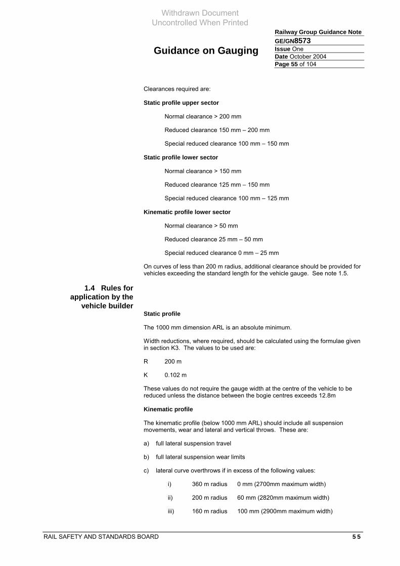
Guidance on Gauging
RAIL SAFETY AND STANDARDS BOARD 5 5
Railway Group Guidance NoteGE/GN8573 Issue One Date October 2004 Page 55 of 104
Clearances required are:
Static profile upper sector
Normal clearance > 200 mm
Reduced clearance 150 mm – 200 mm
Special reduced clearance 100 mm – 150 mm
Static profile lower sector
Normal clearance > 150 mm
Reduced clearance 125 mm – 150 mm
Special reduced clearance 100 mm – 125 mm
Kinematic profile lower sector
Normal clearance > 50 mm
Reduced clearance 25 mm – 50 mm
Special reduced clearance 0 mm – 25 mm
On curves of less than 200 m radius, additional clearance should be provided for vehicles exceeding the standard length for the vehicle gauge. See note 1.5.
1.4 Rules for application by the
vehicle builder Static profile
The 1000 mm dimension ARL is an absolute minimum.
Width reductions, where required, should be calculated using the formulae given in section K3. The values to be used are:
R 200 m
K 0.102 m
These values do not require the gauge width at the centre of the vehicle to be reduced unless the distance between the bogie centres exceeds 12.8m
Kinematic profile
The kinematic profile (below 1000 mm ARL) should include all suspension movements, wear and lateral and vertical throws. These are:
a) full lateral suspension travel
b) full lateral suspension wear limits
c) lateral curve overthrows if in excess of the following values:
i) 360 m radius 0 mm (2700mm maximum width)
ii) 200 m radius 60 mm (2820mm maximum width)
iii) 160 m radius 100 mm (2900mm maximum width)
Withdrawn Document Uncontrolled When Printed

Guidance on Gauging
5 6 RAIL SAFETY AND STANDARDS BOARD
Railway Group Guidance Note GE/GN8573 Issue One Date October 2004 Page 56 of 104
d) downward vertical suspension movements to solid or bumpstop condition
e) downward suspension wear
f) vertical curve overthrows in certain planes.
The following are not to be included:
a) vehicle roll movements
b) axleguard deflections
c) wheel flange to rail clearances
d) wheel flange and rail wear.
In order to allow the infrastructure controller to provide appropriate clearances to the static gauge, the maximum kinematic movement beyond the static profile should be stated. This has traditionally been 100mm and relates to a basic freight suspension. The clearances applicable to the infrastructure allow for this maximum of 100mm of kinematic movement anywhere on the vehicle (static) profile.
All kinematic movement of the bolster should be contained within the kinematic profile shown.
Gauge vertical underclearances are not to be infringed under any condition of loading and wear. Vertical suspension travel should be considered to be to solid or bumpstop condition.
Under the above loading and wear conditions, the vehicle is not to infringe the gauge underclearance planes at 75, 100 and 135 mm ARL when on a concave or convex vertical curve of 500 m radius. The 1000 mm ARL plane is exempt from this. Vertical curve overthrows should be calculated using the formula for Ei and Eo in K3 of this document (using K = 0).
1.5 Notes It should be noted that the width reduction formulae assume a minimum horizontal curve of 200m radius. Since the railway infrastructure in Britain has curve radii as small as 160 m, then the vehicle will be outside of the gauge on curves in the range 160 m to 200 m if built to longer than the dimensions stated. In this case, the infrastructure controller should ensure that, at locations where curves below 200 m are present, clearances are adequately enlarged for these longer vehicles to run.
The profile is based on BR twistlock fastenings. It should be reduced by lateral movements permitted by the amount the load fastening units exceed the 6 mm movement included in the profile for BR twistlock. UIC spigots with a 12.5 mm tolerance require a reduction of 6.5 mm.
Withdrawn Document Uncontrolled When Printed

Guidance on Gauging
RAIL SAFETY AND STANDARDS BOARD 5 7
Railway Group Guidance NoteGE/GN8573 Issue One Date October 2004 Page 57 of 104
Appendix 2 W7 freight gauge (W6a exception gauge for 8’ 0’’ containers)
2.1 Purpose of the W7 freight gauge
The W7 freight gauge is one of two gauges developed as amendments to the W6a gauge (the other is W8 gauge – see Appendix 3).
W7 gauge is designed to accommodate 8’ 0” containers (2438 mm) high.
2.2 Profile of the W7 freight gauge
Withdrawn Document Uncontrolled When Printed

Guidance on Gauging
5 8 RAIL SAFETY AND STANDARDS BOARD
Railway Group Guidance Note GE/GN8573 Issue One Date October 2004 Page 58 of 104
Point X (mm) Y (mm)
1 1410 1000
2 1410 3080
3 1345 3300
4 1115 3531
5 1240 3531
6 1240 3440
7 795 3750
8 152.5 3965 Table 11: Coordinates for static profile
Point X (mm) Y (mm)
1K 680 75
2K 680 100
3K 894 100
4K 894 135
5K 1008 135
6K 1049 152
7K 1219 152
8K 1219 224
9K 1350 280
10K 1350 1000 Table 12: Coordinates for kinematic profile
Items highlighted show the differences from the base W6a gauge.
2.3 Rules for application to the
infrastructure The same rules apply to exception gauges as apply to W6a, as set out in Appendix 1.
2.4 Rules for application by the
vehicle builder The same rules apply to exception gauges as apply to W6a, as set out in Appendix 1. Additionally, attention is drawn to:
a) The lower exception, which applies only to bogie areas subject to nil overthrow on curves. In determining the horizontal coordinates for the lower exception, due account should be taken of all lateral suspension displacements in accordance with the requirements of Appendix 1.
b) The upper exception applies to the body profile. This should be subject to gauge width reductions in accordance with the requirements of Appendix 1.
Withdrawn Document Uncontrolled When Printed

Guidance on Gauging
RAIL SAFETY AND STANDARDS BOARD 5 9
Railway Group Guidance NoteGE/GN8573 Issue One Date October 2004 Page 59 of 104
Appendix 3 W8 freight gauge (W6a exception gauge for 8’ 6” containers)
3.1 Purpose of the W8 freight gauge
The W8 freight gauge is one of two gauges developed as amendments to the W6a gauge (the other is W7 gauge – see Appendix 2).
W8 gauge is designed to accommodate 8’ 6” (2591 mm) high containers.
3.2 Profile of the W8 freight gauge
Withdrawn Document Uncontrolled When Printed

Guidance on Gauging
6 0 RAIL SAFETY AND STANDARDS BOARD
Railway Group Guidance Note GE/GN8573 Issue One Date October 2004 Page 60 of 104
Point X (mm) Y (mm)
1 1410 1000
2 1410 3080
3 1345 3300
4 1271 3568
5 1264 3618
6 976 3618
7 795 3750
8 152.5 3965 Table 13: Coordinates for static profile
Point X (mm) Y (mm)
1K 680 75
2K 680 100
3K 894 100
4K 894 135
5K 1008 135
6K 1049 152
7K 1219 152
8K 1219 224
9K 1350 280
10K 1350 1000 Table 14: Coordinates for kinematic profile
Items highlighted show the differences from the base W6a gauge.
3.3 Rules for application to the
infrastructure The same rules apply to exception gauges as apply to W6a, as set out in Appendix 1.
3.4 Rules for application by the
vehicle builder The same rules apply to exception gauges as apply to W6a, as set out in Appendix 1. Additionally, attention is drawn to:
a) The lower exception, which applies only to bogie areas subject to nil overthrow on curves. In determining the horizontal coordinates for the lower exception, due account should be taken of all lateral suspension displacements in accordance with the requirements of Appendix 1.
b) The upper exception applies to the body profile. This should be subject to gauge width reductions in accordance with the requirements of Appendix 1.
Withdrawn Document Uncontrolled When Printed

Guidance on Gauging
RAIL SAFETY AND STANDARDS BOARD 6 1
Railway Group Guidance NoteGE/GN8573 Issue One Date October 2004 Page 61 of 104
Appendix 4 W9 / SB1c freight gauge
4.1 Purpose of the SB1c freight gauge
SB1c is a swapbody freight vehicle gauge. It is intended to define the maximum size that an SB1c compliant freight vehicle may be built to. The SB1c freight gauge is defined in UIC document 505-3 (as W9), and is considered to be an international freight vehicle gauge. It is defined on drawing PO/CL548 (T&RS, RfD, 28 October 1993).
4.2 Profile of the SB1c freight gauge
The SB1c gauge is in three parts. ‘Inner’ refers to cross-sections between bogie centres, ‘outer’ refers to sections outside of the bogie centres.
SB1c inner (points 1 – 2).
This is the SB1c profile shown between 1000 mm and 780 mm ARL. It is a vehicle body build profile which includes certain lateral kinematic movements.
SB1c inner and outer (points 3 – 11).
Withdrawn Document Uncontrolled When Printed

Guidance on Gauging
6 2 RAIL SAFETY AND STANDARDS BOARD
Railway Group Guidance Note GE/GN8573 Issue One Date October 2004 Page 62 of 104
This is the SB1c profile shown above 1000 mm ARL. It is a vehicle body build profile. It does not include any lateral kinematic movements.
W6a kinematic profile.
SB1c vehicles should comply with W6a profile below 1000 mm ARL. This profile includes all appropriate movements.
Point X (mm) Y (mm)
1 1350 780
2 1350 1000
3 1398 1000
4 1398 3080
5 1333 3300
6 1312.5 3323
7 1312.5 3695
8 1262.5 3701
9 1265.5 3715
10 678 3785
11 140 3965 Table 15: Coordinates for SB1c inner and outer static profile
Point X (mm) Y (mm)
1K 680 75
2K 680 100
3K 894 100
4K 894 135
5K 1008 135
6K 1350 280
7K 1350 1000 Table 16: Coordinates for W6a kinematic profile
4.3 Rules for application to the
infrastructure The rules associated with W6a below 1000 mm ARL apply to this vehicle gauge.
The SB1c gauge relates to the effective position of the track. Where the static envelope only is assessed, the clearances below should be increased to include the effect of possible track tolerances. The adjusted static profile should include lateral and vertical track alignment tolerances, continuous cross level error, and rail sidewear (where this exists).
The SB1c static profile should be adjusted for curve overthrow.
Traditional rules for this gauge have made no reference to kinematic movement of the static profile, but included this in the historic clearances required. The reduction in normal clearance threshold introduced by GC/RT5212 means that
Withdrawn Document Uncontrolled When Printed

Guidance on Gauging
RAIL SAFETY AND STANDARDS BOARD 6 3
Railway Group Guidance NoteGE/GN8573 Issue One Date October 2004 Page 63 of 104
the kinematic movement should be taken into account if the ability to minimise clearances in accordance with GC/RT5212 is to be realised. The clearances quoted for normal, reduced and special reduced clearances include 100mm of kinematic movement of the static profile. Where vehicles do not use traditional freight suspensions (such as track friendly bogies, etc.), the potential kinematic movement of the static profile should be considered. Overthrow should be calculated using formulae described in section K2, using the following values:
Bogie centres 13.5 m
Overall length 19.092 m
Clearances required are:
Static profile upper sector
Normal clearance > 200 mm
Reduced clearance 150 mm – 200 mm
Special reduced clearance 100 mm – 150 mm
Static profile lower sector
Normal clearance > 150 mm
Reduced clearance 125 mm – 150 mm
Special reduced clearance 100 mm – 125 mm
Kinematic profile lower sector
Normal clearance > 50 mm
Reduced clearance 25 mm – 50 mm
Special reduced clearance 0 mm – 25 mm
4.4 Rules for application by the
vehicle builder Static profile SB1c inner and outer above 1000 mm ARL:
a) The 1000 mm dimension ARL is an absolute minimum
b) If bogie centres are less than 13.5 m no width reduction should be applied.
Width reductions should be applied where bogie centres are greater than 13.5 m and should be calculated using the formulae given in section K3. The values to be used are:
R 200 m
K 0.114 m
The profile includes 13 mm of lateral suspension movement. It should be reduced by any lateral kinematic movement greater than 13 mm.
The profile should be further reduced by lateral movements permitted by the amount the load fastening units exceed the 6 mm movement included in the profile for BR twistlock. UIC spigots with a 12.5 mm tolerance require a reduction of 6.5 mm.
Withdrawn Document Uncontrolled When Printed

Guidance on Gauging
6 4 RAIL SAFETY AND STANDARDS BOARD
Railway Group Guidance Note GE/GN8573 Issue One Date October 2004 Page 64 of 104
In order to allow the infrastructure controller to provide appropriate clearances to the static gauge, the maximum kinematic movement beyond the static profile should be stated. This has traditionally been 100mm and relates to a basic freight suspension. The clearances applicable to the infrastructure allow for this maximum of 100mm of kinematic movement anywhere on the vehicle (static) profile.
All kinematic movement of the bolster should be contained within the kinematic profile shown.
Kinematic profile (SB1c inner) between 780 mm and 1000 mm ARL:
The kinematic profile (below 1000 mm ARL) should include the following kinematic movements:
a) full lateral suspension travel
b) full lateral suspension interface wear
c) reduction due to curve throw, Ei
d) load unit displacement tolerances.
The following are not to be included:
i) vehicle roll movements
ii) axleguard deflections
iii) wheel flange to rail clearances
iv) wheel flange and rail wear.
For further information UIC503, Appendix C (Railtrack freight gauge (W9)) for swapbodies and containers on designated Network Rail routes to and from the Channel Tunnel should be consulted.
Withdrawn Document Uncontrolled When Printed

Guidance on Gauging
RAIL SAFETY AND STANDARDS BOARD 6 5
Railway Group Guidance NoteGE/GN8573 Issue One Date October 2004 Page 65 of 104
Appendix 5 W10 swept envelope suite
5.1 Purpose of the W10 vehicle envelope
W10 is not a vehicle gauge.
W10 is a (9’6” x 2500 mm container) swept envelope suite, which may be used to define a route along which any of the component vehicles may run. The purpose of the gauge is to allow a route to be gauged kinematically compliant with a suite of vehicles, enabling less conservative gauging than traditional static gauges.
5.2 W10 profile definition
The W10 profile consists of an overlay of vehicle / load combinations at the specified conditions of speed, curve radius and installed cant, using the appropriate kinematic envelopes.
Figure 7: Example of W10 Swept Envelope Suite on Straight Track at 80km/h
W10 has been released twice, each issue covering slightly different combinations of wagon. (Issue 0 was never formally released, but used for gauge clearance work on the West Coast Main Line. Issue 3 has been used for some assessment, but has never formally been released.)
W10 consists of the following vehicle / load combinations:
Withdrawn Document Uncontrolled When Printed

Guidance on Gauging
6 6 RAIL SAFETY AND STANDARDS BOARD
Railway Group Guidance Note GE/GN8573 Issue One Date October 2004 Page 66 of 104
Issue 0 Issue 1 Issue 2 Issue 3
Alias W10B
W10W
W10FU W10-
Load 9’6” x 2500 9’6” x 2600 9’6” x 2500 9’6” x 2600
Wagon Description
IKA Megafret (Remafer) * * * *
FSA 2nd Gen. Freightliner * * * *
IFA Multifret Single & Twin
* * * *
KFA Tiphook UK * * * (note)
KAE Babcock Mega 3 *
FFA 1st Generation *
FLA PD Lowliner *
IFB *
FCA Thrall (Naco Bogies) *
FKA Europa Flat * *
FIA Eurotwin UIC RIV * *
FTA 2nd Gen. Freightliner * *
Table 17: Components of W10 swept envelope
The aliases refer to:
a) W10B ‘Big box’
b) W10W ‘Wide’
c) W10FU ‘Freight upgrade’
d) W10- Excludes wagons with >980 mm deck height
Note: The KFA wagon has a 1000 mm nominal deck height. However, this wagon has BR twistlock fastenings (with a tolerance of ± 6 mm) rather than the UIC spigots (which have a tolerance of ± 12.5 mm). Accordingly, the load width is effectively 13 m narrower at full height. This keeps the load within the envelope occupied by other wagons in the suite. Its removal makes only minimal difference where the kinematic envelope of this wagon differs from others.
5.3 Rules for application to the
infrastructure Each vehicle is applied individually, calculating the effects of curve overthrow, kinematic movement and tolerances. It is applied using the concept of ‘effective
Withdrawn Document Uncontrolled When Printed

Guidance on Gauging
RAIL SAFETY AND STANDARDS BOARD 6 7
Railway Group Guidance NoteGE/GN8573 Issue One Date October 2004 Page 67 of 104
position of the track’. Normal, reduced and special reduced clearance values are as stated in GC/RT5212.
Infrastructure gauging should be performed using the absolute gauging methodology with appropriate clearances and infrastructure tolerances.
5.4 Rules for application by vehicle
builder Wagons should comply with the W6a gauge described in this document.
Comparative gauging may be performed using one or more of the candidate vehicles to ensure that the load is contained within the swept envelope described by the family of vehicles listed.
Withdrawn Document Uncontrolled When Printed

Guidance on Gauging
6 8 RAIL SAFETY AND STANDARDS BOARD
Railway Group Guidance Note GE/GN8573 Issue One Date October 2004 Page 68 of 104
Appendix 6 W12 composite swept envelope
6.1 Purpose of the W12 vehicle envelope
W12 is not a vehicle gauge.
W12 is a composite swept envelope describing a notional freight load (9’6” x 2600 mm) carried by a variety of wagons. The purpose of the gauge is to define a swept envelope for comparative gauging which may be used as the basis of dynamic wagon design. From an infrastructure perspective, routes cleared (through the normal absolute kinematic process) will accept any vehicle fitting within the defined W12 swept envelope.
Note that issue 1 was a swept envelope suite, and issues 2 and 3 are composite swept envelopes.
Withdrawn Document Uncontrolled When Printed

Guidance on Gauging
RAIL SAFETY AND STANDARDS BOARD 6 9
Railway Group Guidance NoteGE/GN8573 Issue One Date October 2004 Page 69 of 104
Issue 1 Issue 2 Issue 3
Alias With FAA Without FAA
Load 9’6 x 2600 9’6 x 2600 9’6 x 2600
Wagon Description
FCA Thrall (Naco Bogies) * * *
KAE Babcock Mega 3 * * *
FIA Eurotwin UIC RIV * * *
IFA Multifret Single & Twin
* * *
IKA Megafret (Remafer) * *
FKA Europa Flat * *
FAA EWS Container Carrier
*
FFA 1st Generation * *
FGA 1st Generation * *
FFA 2nd Generation * * *
FGA 2nd Generation * * *
FSA 2nd Gen. Freightliner * * *
FTA 2nd Gen Freightliner * * *
KFA Tiphook * * *
IJA Unilog 60’ * *
KHA Tiphook 60’ * *
PD T25 Nominal * *
Thrall Eurospine *
AAE Megafret *
IFB Transfesa *
Table 18: Components of W12 swept envelope
In issue 1, the loads consisted of standard containers. In issues 2 and 3, the load consists of a composite of:
a) the uppermost portion of SB1c (W9) gauge
b) the upper portion of the UICS348 coded profile
Withdrawn Document Uncontrolled When Printed

Guidance on Gauging
7 0 RAIL SAFETY AND STANDARDS BOARD
Railway Group Guidance Note GE/GN8573 Issue One Date October 2004 Page 70 of 104
c) a 2600 mm wide box between 700 mm and 3900 mm ARL, with a 25 mm x 50 mm notch in the upper outer corner (filled in with a diagonal line).
It excludes the wagon itself, which is assumed to comply with the W6a vehicle gauge. Issues 2 and 3 are fully defined in document ITLR/T8328/001, produced by Interfleet Technology Ltd for Network Rail Infrastructure (Railtrack).
The vehicle envelope is defined for particular combinations of radius, speed, and installed cant. In order to provide a full spectrum of operating environments, the envelope consists of 11,148 individual profiles. The profile is asymmetric, reflecting trundle speed and cant excess to the inside, and maximum speed and cant deficiency to the outside.
An additional suite of profiles has been produced reflecting the profiles as modified by the application of a 35 m/s wind load. It should be noted that there is, as yet, no standard methodology for predicting the effects of wind loading.
Versions of W12 have been produced with and without wind loading (see infrastructure rules).
6.2 The W12 profile By its nature, the W12 swept envelope does not have a defined profile in the same way that the C1 or W6a vehicle gauges have profiles. The base W12 profile is derived from components of W9, UIC S348 profile and a 2600mm wide box. If a load that fits within the base profile is carried on any of the wagons listed in table 18, then the combination should comply with W12.
Figure 8: W12 Base Profile
Withdrawn Document Uncontrolled When Printed

Guidance on Gauging
RAIL SAFETY AND STANDARDS BOARD 7 1
Railway Group Guidance NoteGE/GN8573 Issue One Date October 2004 Page 71 of 104
The W12 swept envelope varies according to specific local conditions. The following example shows a W12 envelope developed for the following conditions:
a) no wind
b) 96 km/h
c) 1024 m radius curve
d) 100 mm installed cant.
0
500
1000
1500
2000
2500
3000
3500
4000
4500
5000
-2500 -2000 -1500 -1000 -500 0 500 1000 1500 2000 2500
x ( mm)
Figure 9: Example of typical W12 swept envelope
6.3 Rules for application to the
infrastructure Being a vehicle swept envelope, which includes curve overthrow and kinematic movements, it is applied using the concept of ‘effective position of the track’. Normal, reduced and special reduced clearance values are as stated in GC/RT5212.
Infrastructure gauging should be performed using the absolute gauging methodology with appropriate clearances and infrastructure tolerances.
Withdrawn Document Uncontrolled When Printed

Guidance on Gauging
7 2 RAIL SAFETY AND STANDARDS BOARD
Railway Group Guidance Note GE/GN8573 Issue One Date October 2004 Page 72 of 104
In ‘exposed locations’, the alternative (with 35 m/s wind loading) profiles may be used as part of a risk assessment exercise.
The W12 envelopes contain the following movements and tolerances:
a) horizontal throw
b) kinematic and static rolls, sways and drops
c) dynamic cross-level error (10 mm)
d) static cross-level error (10 mm) – (normally considered to be an infrastructure tolerance)
e) wheel flange clearance (8 mm)
f) wheel flange wear (5 mm)
g) wheel wear.
Movements and tolerances that should be added are:
a) vertical curvature
b) vertical and lateral track alignment
c) rail sidewear.
Vertical curvature should be considered where appropriate. The formulae to be used are:
Ti = 30005/R - 0.0005
To = 21751/R + 0.0003
Where:
Ti is the throw towards the centre of the curve in metres
To is the throw towards the outside of the curve in metres
R is the vertical curve radius in metres.
6.4 Rules for application by the
vehicle builder Vehicles built to comply with W12 gauge should conform to the W6a gauge when unloaded and it should be ensured that the size and movements of the container remain within the appropriate envelope under both tare and laden conditions.
Vehicles not shown in table 18 must be shown to be capable of maintaining a loading with the W12 base profile within the W12 Composite Swept Envelope at all times in order to comply with W12.
In this context, candidate vehicles are gauged using the comparative gauging process over a representative selection of route conditions which provide full cover for those which will be experienced in practice. The W12 envelope includes lateral, vertical and roll movements of the suspension, horizontal curve overthrows, dynamic cross-level error, flangeway clearance and wheel flange wear. No infrastructure tolerances (such as rail sidewear, lateral or vertical track alignment and static cross-level error) are included.
Withdrawn Document Uncontrolled When Printed

Guidance on Gauging
RAIL SAFETY AND STANDARDS BOARD 7 3
Railway Group Guidance NoteGE/GN8573 Issue One Date October 2004 Page 73 of 104
Appendix 7 C1 gauge
7.1 Purpose of the C1 gauge
C1 gauge is a passenger vehicle gauge. It is intended to define the maximum size to which a C1 compliant passenger vehicle may be built.
7.2 Profile of the C1 gauge
The C1 gauge is defined by drawing CCE 891-61 Issue D, from which the following diagram is an extract. The gauge is in two parts, one (static) for the vehicle body and another (kinematic) for the items not subject to overthrow, such as bogies. It applies to the following vehicles:
a) 19,354 mm over headstocks with 14,173 mm bogie centres
b) 17,373 mm over headstocks with 12,192 mm bogie centres.
Parts of the profile are described by arcs. These have been shown on the drawing, together with the extracted points. The points used are within 1 mm of the true circular arcs.
Figure 10: Diagram of C1 gauge
Withdrawn Document Uncontrolled When Printed

Guidance on Gauging
7 4 RAIL SAFETY AND STANDARDS BOARD
Railway Group Guidance Note GE/GN8573 Issue One Date October 2004 Page 74 of 104
Static Kinematic Point X Y Point X Y
1 1041.5 152 1K 1255 280 2 1041.5 178 2K 1255 308 3 1041.5 229 3K 1295 305 4 1105 229 4K (1105) (178) 5 1105 280 5K 1295 1083 6 1143 280 7 1143 915 8 1194 915 9 1219 1083 10 1372.5 1083 11 1372.5 1137 12 1346 1232 13 1360 1312 14 1369 1392 15 1410 1473 16 1410 2603.5 17 1371 2965 18 1368 3051 19 1362 3137 20 1271 3340 21 1226 3399 22 1171 3450 23 794 3747 24 690 3791 25 586.5 3836 26 471 3863 27 354 3884 28 237 3899 29 119 3909 30 0 3912 31 0 3772 32 121 3769 33 241 3758 34 361 3742 35 480 3718 36 597 3688 37 712 3652 38 825 3609 39 936 3560 40 1043 3505 41 1146 3445 42 1184 3414 43 1218 3379 44 1248 3340 45 1324 3111.5 46 1360 2603.5 47 1372 2321 48 1372 1473
Table 19: Coordinates of C1 gauge
Withdrawn Document Uncontrolled When Printed

Guidance on Gauging
RAIL SAFETY AND STANDARDS BOARD 7 5
Railway Group Guidance NoteGE/GN8573 Issue One Date October 2004 Page 75 of 104
Arc Centre Point X Y Radius (mm)
12 213 1473 1159 13 14 17 1689 2896 3061 18 19 23 0 2184 1749 24 25 25 0 1600 2312 26 27 28 29 30 31 0 1600 2172 32 33 34 35 36 37 38 39 40 41 42 42 853 3058 485 43 44 Table 20: Arc Details
The hatched area around the body is available only to frangible items.
Items could be considered frangible if, when struck in the direction of travel, they fail in a manner that does not create a risk to people on board or in the vicinity of the vehicle.
The mechanical strength of frangible items should not be greater than that of equivalent items on existing C1 gauge vehicles, eg roof ventilators on Mark I coaches.
When struck, the item should either:
a) remain attached to the vehicle, or
b) be sufficiently small and lightweight that it will not cause risk to people close to the vehicle (eg passengers on station platforms).
The failure of a frangible item should be shown not to affect the safe operation of the vehicle.
Withdrawn Document Uncontrolled When Printed

Guidance on Gauging
7 6 RAIL SAFETY AND STANDARDS BOARD
Railway Group Guidance Note GE/GN8573 Issue One Date October 2004 Page 76 of 104
The hatched area bounded by points 1 - 4 is permitted only on bogie frames between wheelsets.
Heights above 1118 mm are for non-worn vehicles.
Heights below 1118 mm are for fully worn vehicles.
7.3 Rules for application to the
infrastructure The C1 gauge should be used according to the vehicle gauge methodology. Appropriate clearances (described below) are required.
The C1 gauge relates to the effective position of the track.
The C1 body profile should be adjusted for curve overthrow.
Traditional rules for this gauge have made no reference to kinematic movement of the static profile, but included this in the historic clearances required. The reduction in normal clearance threshold introduced by GC/RT5212 means that the kinematic movement should be taken into account if the ability to minimise clearances in accordance with GC/RT5212 is to be realised. The clearances quoted for normal, reduced and special reduced clearances include 150mm of kinematic movement of the static profile. Where vehicles do not use traditional freight suspensions (such as track friendly bogies, etc.), the potential kinematic movement of the static profile should be considered. Clearances required are:
Body profile upper sector
Normal clearance > 250 mm
Reduced clearance 200 mm – 250 mm
Special reduced clearance 150 mm – 200 mm
Body profile lower sector
Normal clearance > 200 mm
Reduced clearance 175 mm – 200 mm
Special reduced clearance 150 mm – 175 mm
Bolster profile lower sector
Normal clearance > 50 mm
Reduced clearance 25 mm – 50 mm
Special reduced clearance 0 mm – 25 mm
7.4 Rules for application by the
vehicle builder The C1 gauge defines the maximum size to which the vehicle may be built and the maximum dimensions of vehicle length and bogie centres.
In order to allow the infrastructure controller to provide appropriate clearances to the static gauge, the maximum kinematic movement beyond the static profile should be stated. This has traditionally been 150 mm and relates to a basic
Withdrawn Document Uncontrolled When Printed

Guidance on Gauging
RAIL SAFETY AND STANDARDS BOARD 7 7
Railway Group Guidance NoteGE/GN8573 Issue One Date October 2004 Page 77 of 104
metal sprung passenger suspension. The clearances applicable to the infrastructure allow for this maximum of 100 mm of kinematic movement anywhere on the vehicle (static) profile.
All kinematic movement of the bolster should be contained within the kinematic profile shown.
Width reduction does not apply.
This gauge assumes the use of specific bogies, notably BR1, BR2 (heavy duty), B4, B5 (heavy duty) and cast Commonwealth bogies.
Withdrawn Document Uncontrolled When Printed

Guidance on Gauging
7 8 RAIL SAFETY AND STANDARDS BOARD
Railway Group Guidance Note GE/GN8573 Issue One Date October 2004 Page 78 of 104
Appendix 8 C1 (Appendix A) gauge
8.1 Purpose of the C1 (Appendix A) gauge
C1 (Appendix A) gauge is a passenger vehicle gauge. It is intended to define the maximum size to which a C1 (Appendix A) compliant passenger vehicle may be built.
Historically, two families of vehicle have been built to C1 (Appendix A) gauge; the PEP derived stock (Classes 313, 314, 315, 507 and 508), and the Mark III multiple unit stock (Classes 150, 210, 317, 318, 319, 320, 321, 322, 325, 455 and 456).
8.2 Profile of the C1 (Appendix A) gauge
The C1 Appendix A gauge is defined by drawing C-A0-39 (BR CM&EE Dept 08 April 1974), which may be obtained from:
Serco Raildata Derwent House rtc Business Park London Road Derby DE24 8UP
This gauge is an extension of the original C1 gauge for passenger vehicles (Appendix 7). C1 Appendix A extends into the ‘frangible’ zone of C1, but all ‘frangible’ items such as door handles and handrails are recessed in C1 Appendix A. The gauge is in two parts, one (static) for the vehicle body and another (kinematic) for the items not subject to overthrow, such as bogies. It applies to the following vehicles:
a) 19,354 mm over headstocks with 14,173 mm bogie centres
b) 17,373 mm over headstocks with 12,192 mm bogie centres.
No vehicles are known to have been built to the shorter dimension (b).
Withdrawn Document Uncontrolled When Printed

Guidance on Gauging
RAIL SAFETY AND STANDARDS BOARD 7 9
Railway Group Guidance NoteGE/GN8573 Issue One Date October 2004 Page 79 of 104
Figure 11: Diagram of C1 (Appendix A) gauge
Withdrawn Document Uncontrolled When Printed

Guidance on Gauging
8 0 RAIL SAFETY AND STANDARDS BOARD
Railway Group Guidance Note GE/GN8573 Issue One Date October 2004 Page 80 of 104
Static Kinematic
Point X Y Point X Y
1 1041.5 152 1K 1255 280
2 1041.5 229 2K 1255 305
3 1105 229 3K 1295 305
4 1105 280 4K 1295 915
5 1143 280
6 1143 915
7 1219 915
8 1372 1118
9 1397 1220
10 1410 1372
11 1410 2590
12 1362 3137
13 1283 3340
14 794 3747
15 587 3836
16 177.5 3912 Table 21: Coordinates of C1 (Appendix A) gauge
Heights above 1118 mm are for non-worn vehicles.
Heights below 1118 mm are for fully worn vehicles.
8.3 Rules for application to the
infrastructure The C1 (Appendix A) gauge should be used according to the vehicle gauge methodology. Appropriate clearances (described below) are required.
The C1 (Appendix A) gauge relates to the effective position of the track.
The C1 (Appendix A) body profile should be adjusted for curve overthrow.
Traditional rules for this gauge have made no reference to kinematic movement of the static profile, but included this in the historic clearances required. The reduction in normal clearance threshold introduced by GC/RT5212 means that the kinematic movement should be taken into account if the ability to minimise clearances in accordance with GC/RT5212 is to be realised. The clearances quoted for normal, reduced and special reduced clearances include 150mm of kinematic movement of the static profile. Where vehicles do not use traditionally sprung suspensions (such as air bags, etc.), the potential kinematic movement of the static profile should be considered. Clearances required are:
Body profile upper sector
Normal clearance > 250 mm
Reduced clearance 200 mm – 250 mm
Withdrawn Document Uncontrolled When Printed

Guidance on Gauging
RAIL SAFETY AND STANDARDS BOARD 8 1
Railway Group Guidance NoteGE/GN8573 Issue One Date October 2004 Page 81 of 104
Special reduced clearance 150 mm – 200 mm
Body profile lower sector
Normal clearance > 250 mm
Reduced clearance 225 mm – 250 mm
Special reduced clearance 200 mm – 225 mm
Bolster profile lower sector
Normal clearance > 50 mm
Reduced clearance 25 mm – 50 mm
Special reduced clearance 0 mm – 25 mm
8.4 Rules for application by the
vehicle builder The C1 (Appendix A) gauge defines the maximum size the vehicle may be built to, and the maximum dimensions of vehicle length and bogie centres.
In order to allow the infrastructure controller to provide appropriate clearances to the static gauge, the maximum kinematic movement beyond the static profile should be stated. This has traditionally been 150mm and relates to a basic metal sprung passenger suspension. The clearances applicable to the infrastructure allow for this maximum of 100mm of kinematic movement anywhere on the vehicle (static) profile.
All kinematic movement of the bolster should be contained within the kinematic profile shown.
Width reduction does not apply.
This gauge assumes the use of specific bogies (based upon the Continental 684 and 732 airbags), notably series 3 (BX1, BT13, etc) or series 7 bogies.
Withdrawn Document Uncontrolled When Printed

Guidance on Gauging
8 2 RAIL SAFETY AND STANDARDS BOARD
Railway Group Guidance Note GE/GN8573 Issue One Date October 2004 Page 82 of 104
Appendix 9 C3 ‘gauge’
9.1 Purpose of the C3 gauge
C3 is a designation for the Mark III passenger coach, which is a 23 m vehicle. C3 gauge refers to the swept envelope of a Mark III passenger coach. A C3 gauge has never been defined, and represents an ambiguous term.
For comparative gauging, if C3 is required, a Mark III coach should be used as a reference vehicle
Withdrawn Document Uncontrolled When Printed

Guidance on Gauging
RAIL SAFETY AND STANDARDS BOARD 8 3
Railway Group Guidance NoteGE/GN8573 Issue One Date October 2004 Page 83 of 104
Appendix 10 Locomotive gauge
10.1 Purpose of locomotive gauge
Locomotive gauge is a vehicle gauge for locomotives.
10.2 Profile of the locomotive gauge
Locomotive gauge is defined on drawing L-A1-1806 (BR CM&EE Dept 12 March 1970).
Figure 12: Locomotive Gauge
The above drawing is an extract from drawing L-A0-1806. The actual drawing should be consulted for further details.
The locomotive gauge is in two parts:
a) A static profile vehicle build profile.
b) A thrown profile is not to be exceeded on a 200 m curve.
Withdrawn Document Uncontrolled When Printed
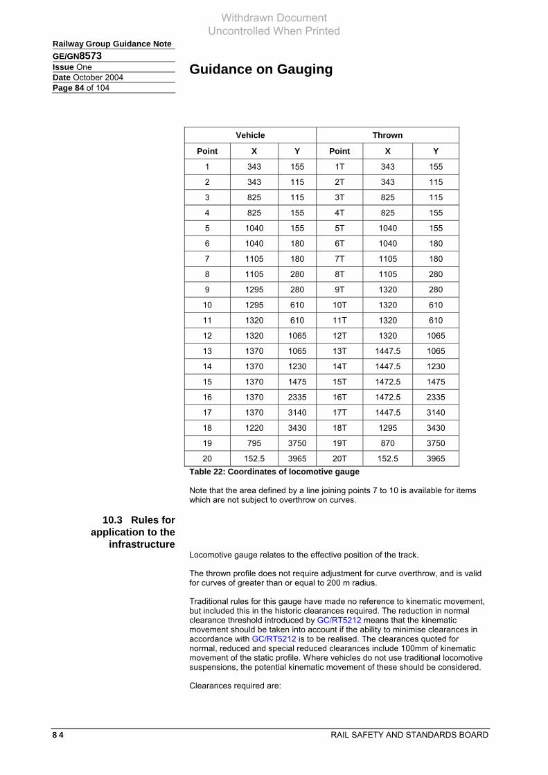
Guidance on Gauging
8 4 RAIL SAFETY AND STANDARDS BOARD
Railway Group Guidance Note GE/GN8573 Issue One Date October 2004 Page 84 of 104
Vehicle Thrown
Point X Y Point X Y
1 343 155 1T 343 155
2 343 115 2T 343 115
3 825 115 3T 825 115
4 825 155 4T 825 155
5 1040 155 5T 1040 155
6 1040 180 6T 1040 180
7 1105 180 7T 1105 180
8 1105 280 8T 1105 280
9 1295 280 9T 1320 280
10 1295 610 10T 1320 610
11 1320 610 11T 1320 610
12 1320 1065 12T 1320 1065
13 1370 1065 13T 1447.5 1065
14 1370 1230 14T 1447.5 1230
15 1370 1475 15T 1472.5 1475
16 1370 2335 16T 1472.5 2335
17 1370 3140 17T 1447.5 3140
18 1220 3430 18T 1295 3430
19 795 3750 19T 870 3750
20 152.5 3965 20T 152.5 3965 Table 22: Coordinates of locomotive gauge
Note that the area defined by a line joining points 7 to 10 is available for items which are not subject to overthrow on curves.
10.3 Rules for application to the
infrastructure Locomotive gauge relates to the effective position of the track.
The thrown profile does not require adjustment for curve overthrow, and is valid for curves of greater than or equal to 200 m radius.
Traditional rules for this gauge have made no reference to kinematic movement, but included this in the historic clearances required. The reduction in normal clearance threshold introduced by GC/RT5212 means that the kinematic movement should be taken into account if the ability to minimise clearances in accordance with GC/RT5212 is to be realised. The clearances quoted for normal, reduced and special reduced clearances include 100mm of kinematic movement of the static profile. Where vehicles do not use traditional locomotive suspensions, the potential kinematic movement of these should be considered.
Clearances required are:
Withdrawn Document Uncontrolled When Printed

Guidance on Gauging
RAIL SAFETY AND STANDARDS BOARD 8 5
Railway Group Guidance NoteGE/GN8573 Issue One Date October 2004 Page 85 of 104
Upper sector
Normal clearance > 200 mm
Reduced clearance 150 mm – 200 mm
Special reduced clearance 100 mm – 150 mm
Lower sector
Normal clearance > 150 mm
Reduced clearance 125 mm – 150 mm
Special reduced clearance 100 mm – 125 mm
10.4 Rules for application by vehicle
builder The static profile is the vehicle build profile.
The thrown profile is not to be exceeded on a 200 m curve.
The total vehicle kinematic movement of the body is not to exceed 100 mm at any point on the vehicle.
Width reduction does not apply.
Withdrawn Document Uncontrolled When Printed

Guidance on Gauging
8 6 RAIL SAFETY AND STANDARDS BOARD
Railway Group Guidance Note GE/GN8573 Issue One Date October 2004 Page 86 of 104
Appendix 11 UK1 gauge
11.1 Purpose of the UK1 gauge
UK1 gauge is published in the High-Speed TSI as annex M of the infrastructure TSI and annex C of the rolling stock TSI. However, this is only a set of co-ordinates with no supporting rules. It is not a gauge for Eurostar vehicles.
This appendix is designed to present the known information regarding the UK1 gauge, together with a set of derived rules.
The aspiration of this gauge was to define high-speed interoperable routes in Britain as those that could accept Eurostar traffic. The UK1 gauge defined will not achieve this, since the behaviour of the Eurostar (Class 373 vehicle rake) in relation to the defined static profile is a complicated relationship defined by MSER42. Gauging for Eurostar vehicles is described in Appendix 13.
Note: A revised UK1 gauge is currently being developed to supersede UK1 gauge published in the High-Speed TSIs.
11.2 The UK1 profile
Figure 13: UK1 Gauge
Withdrawn Document Uncontrolled When Printed

Guidance on Gauging
RAIL SAFETY AND STANDARDS BOARD 8 7
Railway Group Guidance NoteGE/GN8573 Issue One Date October 2004 Page 87 of 104
The UK1 gauge is in two parts:
a) A static (body) profile (above 1100 mm ARL) is the vehicle body build profile. It does not include any lateral kinematic movements.
b) A kinematic (bogie, etc) profile (below 1100 mm ARL), which includes all appropriate movements.
Point X (mm) Y (mm)
1 1410 1100
2 1410 3286
3 1320 3567
4 150 3965 Table 23: Coordinates for static profile
Point X (mm) Y (mm)
1K 1360 125
2K 1360 1100 Table 24: Coordinates for kinematic profile
Note on the origin of co-ordinates:
The origins of the points on this gauge are from a variety of sources. A principal source of data is the GEC ALSTHOM drawing TRK8605201 that describes the static profile of the Class 373 (Eurostar) power car in relation to SNCF GA gauge and the BR W6a vehicle gauge. In general the Class 373 static profile fits within the W6a profile, the exceptions being around cantrail. However, the throw and kinematic behaviour of the Class 373 is completely different to W6a compliant vehicles.
On the body profile:
Point 1 is the semi-width of W6a – 1410 mm (compare semi-width of Class 373 at 1407 mm at waist), and at a height of 1100 mm. The height dimension is satisfactory to accommodate Class 373, and less demanding on infrastructure designed to be compliant with W6a (1000 mm).
Point 2 is the semi-width of W6a, but at the increased cantrail height of 3286 mm of the Class 373. This is higher than W6a, and would not be compliant with W6a cleared routes.
Point 3 does not appear to relate to either W6a or Class 373. The semi-width of 2640 mm at a height of 3567 mm corresponds to an 8’6” x 2600 mm container (allowing 10 mm fastening tolerance) loaded on a 1100 mm deck freight wagon (KHA).
Point 4 compares 150 mm semi-width at 3965 mm with the W6a dimension of 302.5 mm semi-width at 3965 mm ARL.
On the kinematic profile:
Point 1 semi-width of 1360 mm corresponds to the semi-width of the Eurostar axle box cover (1358 mm) at a height of 125 mm ARL, this being the bottom of the Class 373 gearbox housing. This dimension is not consistent with W6a or compliant with standard platforms.
Withdrawn Document Uncontrolled When Printed

Guidance on Gauging
8 8 RAIL SAFETY AND STANDARDS BOARD
Railway Group Guidance Note GE/GN8573 Issue One Date October 2004 Page 88 of 104
Point 2 semi-width of 1360 mm as above, the height of 1100 mm ARL corresponding to the lower limit of the static profile. This dimension is again not consistent with W6a, nor compliant with standard platforms.
11.3 Rules for application to the
infrastructure The UK1 gauge relates to the effective position of the track.
The UK1 static profile should be adjusted for curve overthrow.
The rules for this gauge made no reference to kinematic movement of the vehicle static profile, but assumed that this would be consumed within a generous clearance regime. The reduction in normal clearance threshold introduced by GC/RT5212 means that the kinematic movement should be taken into account if the ability to minimise clearances in accordance with GC/RT5212 is to be realised. The clearances quoted for normal, reduced and special reduced clearances include 100mm of kinematic movement of the static profile. Where vehicles have more than this kinematic movement, this should be considered in the clearances to the static profile that may be required.
The UK1 kinematic profile should not be adjusted for curve overthrow.
Overthrow should be calculated using formulae described in L2 of this document, using the following values:
Bogie centres 12.8 m
Overall length 18.103 m
Clearances required by GC/RT5212 issue 1 are:
Static profile upper sector
Normal clearance > 200 mm
Reduced clearance 150 mm – 200 mm
Special reduced clearance 100 mm – 150 mm
Static profile lower sector
Normal clearance > 150 mm
Reduced clearance 125 mm – 150 mm
Special reduced clearance 100 mm – 125 mm
Kinematic profile lower sector
Normal clearance > 50 mm
Reduced clearance 25 mm – 50 mm
Special reduced clearance 0 mm – 25 mm
Withdrawn Document Uncontrolled When Printed

Guidance on Gauging
RAIL SAFETY AND STANDARDS BOARD 8 9
Railway Group Guidance NoteGE/GN8573 Issue One Date October 2004 Page 89 of 104
11.4 Rules for application by the
vehicle builder Static profile
Since the widths of the vehicle relate primarily to W6a, the rule set for W6a is deemed appropriate.
The 1100 mm dimension ARL is an absolute minimum.
Width reductions, where required, should be calculated using the formulae given in Appendix 1. The values to be used are:
R = 200 m
K = 0.102 m
These values do not require the gauge width at the centre of the vehicle to be reduced unless the distance between the bogie centres exceeds 12.8 m.
Kinematic profile
The kinematic profile (below 1100 mm ARL) should include all kinematic movements, wear and lateral and vertical throws. These are:
a) full lateral suspension travel
b) full lateral suspension wear limits
c) lateral curve overthrows if in excess of the following values:
i) 360 m radius 0 mm
ii) 200 m radius 60 mm
iii) 160 m radius 100 mm
d) downward vertical suspension movements to solid or bumpstop condition
e) downward suspension wear
f) vertical curve overthrows.
The following are not to be included:
a) vehicle roll movements
b) axleguard deflections
c) wheel flange to rail clearances
d) wheel flange and rail wear.
In order to allow the infrastructure controller to provide appropriate clearances to the static gauge, the maximum kinematic movement beyond the static profile should be stated. This has traditionally been 100mm and relates to a basic freight suspension. The clearances applicable to the infrastructure allow for this maximum of 100mm of kinematic movement anywhere on the vehicle (static) profile.
All kinematic movement of the bolster should be contained within the kinematic profile shown.
Withdrawn Document Uncontrolled When Printed

Guidance on Gauging
9 0 RAIL SAFETY AND STANDARDS BOARD
Railway Group Guidance Note GE/GN8573 Issue One Date October 2004 Page 90 of 104
Gauge vertical underclearances are not to be infringed under any condition of loading and wear. Vertical suspension travel should be considered to be to solid or bumpstop condition.
Under the above loading and wear conditions, the vehicle is not to infringe the gauge underclearance when on a concave or convex vertical curve of 500 m radius. Vertical curve overthrows should be calculated using the formula for Ei and Eo in K3 of this document (using K = 0). The 1100 mm ARL plane is exempt from this.
Withdrawn Document Uncontrolled When Printed

Guidance on Gauging
RAIL SAFETY AND STANDARDS BOARD 9 1
Railway Group Guidance NoteGE/GN8573 Issue One Date October 2004 Page 91 of 104
Appendix 12 UK2 gauge
12.1 Purpose of the UK2
gauge UK2 gauge has been circulated in Britain but never submitted. It is intended to provide a British universal freight gauge for container traffic, suitable for reference by the conventional TSI.
UK2 has been defined in draft Network Rail Company Standard RT/CES/036 issue 2 as VG9 (Appendix 16).
This appendix is designed to present the known information regarding the UK2 gauge, together with a set of derived rules.
UK2 gauge aspires to define a base for interoperability of freight container traffic. Whilst the gauge developed can accommodate 9’6” x 2600 mm containers on certain wagons, it is larger than required in certain dimensions, and would only be applicable to a small part of the British network.
12.2 The UK2 profile
Figure 14: UK2 Gauge
Withdrawn Document Uncontrolled When Printed

Guidance on Gauging
9 2 RAIL SAFETY AND STANDARDS BOARD
Railway Group Guidance Note GE/GN8573 Issue One Date October 2004 Page 92 of 104
The UK2 gauge is in two parts:
A static (body) profile (above 1000 mm ARL) is the vehicle body build profile. It does not include any lateral kinematic movements.
A kinematic (bogie, etc) profile (below 1000 mm ARL), which includes all appropriate movements.
Point X (mm) Y (mm)
1 1340 1000
2 1340 3939 Table 25: Coordinates for static profile
Point X (mm) Y (mm)
1K 1350 200
2K 1350 1000 Table 26: Coordinates for kinematic profile
Note on the origin of co-ordinates:
The origin of points on this gauge is principally W6a and specific wagon / load combinations dimensions.
On the body profile:
Point 1 is wider than a 2600 mm wide container attached with UIC spigots (1312.5 mm). The height of 1000 mm corresponds to W6a and the deck height of a KFA wagon.
Point 2 is similar width, and corresponds to a container of 9’8” on a KFA wagon. It is also known as W14, representing:
a) 2760 mm high intermodal on UIC (1180 mm) wagon
b) 2995 mm high intermodal unit on Multifret (945 mm) wagon
c) 3115 mm high intermodal unit on Megafret (825 mm) wagon.
On the kinematic profile:
Point 1 semi-width of 1350 mm and height of 1000 mm ARL corresponds to W6a.
Point 2 semi-width of 1350 mm as above, the height of 200 mm ARL does not correspond to any known dimension, and is not compliant with W6a.
12.3 Rules for application to the
infrastructure The UK2 gauge relates to the effective position of the track.
The UK2 static profile should be adjusted for curve overthrow
The rules for this gauge have made no reference to kinematic movement of the static profile, but included this in the historic clearances required for traditional
Withdrawn Document Uncontrolled When Printed

Guidance on Gauging
RAIL SAFETY AND STANDARDS BOARD 9 3
Railway Group Guidance NoteGE/GN8573 Issue One Date October 2004 Page 93 of 104
freight suspensions. The reduction in normal clearance threshold introduced by GC/RT5212 means that the kinematic movement should be taken into account if the ability to minimise clearances in accordance with GC/RT5212 is to be realised. The clearances quoted for normal, reduced and special reduced clearances include 100 mm of kinematic movement of the static profile. Where vehicles do not use traditional freight suspensions (such as track friendly bogies, etc.), the potential kinematic movement of the static profile should be considered.
The UK2 kinematic profile should not be adjusted for curve overthrow.
Overthrow should be calculated using formulae described in L2 of this document, using the following values (based upon the KFA wagon):
Bogie centres 14.020 m
Overall length 19.354 m
Clearances required by GC/RT5212 issue 1 are:
Static profile upper sector
Normal clearance > 200 mm
Reduced clearance 150 mm – 200 mm
Special reduced clearance 100 mm – 150 mm
Static profile lower sector
Normal clearance > 150 mm
Reduced clearance 125 mm – 150 mm
Special reduced clearance 100 mm – 125 mm
Kinematic profile lower sector
Normal clearance > 50 mm
Reduced clearance 25 mm – 50 mm
Special reduced clearance 0 mm – 25 mm
12.4 Rules for application by the
vehicle builder Static profile:
Width reductions, where required, should be calculated using the formulae given in Appendix 1. The values to be used are:
R = 200 m
K = 0.123 m
These values do not require the gauge width at the centre of the vehicle to be reduced unless the distance between the bogie centres exceeds 14.020 m.
Kinematic profile:
The kinematic profile (below 1000 mm ARL) should include all kinematic movements, wear and lateral and vertical throws. These are:
Withdrawn Document Uncontrolled When Printed

Guidance on Gauging
9 4 RAIL SAFETY AND STANDARDS BOARD
Railway Group Guidance Note GE/GN8573 Issue One Date October 2004 Page 94 of 104
a) full lateral suspension travel
b) full lateral suspension wear limits
c) lateral curve overthrows if in excess of the following values:
i) 360 m radius 0 mm
ii) 200 m radius 60 mm
iii) 160 m radius 100 mm
d) downward vertical suspension movements to solid or bumpstop condition
e) downward suspension wear
f) vertical curve overthrows.
The following are not to be included:
a) vehicle roll movements
b) axleguard deflections
c) wheel flange to rail clearances
d) wheel flange and rail wear.
In order to allow the infrastructure controller to provide appropriate clearances to the static gauge, the maximum kinematic movement beyond the static profile should be stated. This has traditionally been 100mm and relates to a basic freight suspension. The clearances applicable to the infrastructure allow for this maximum of 100 mm of kinematic movement anywhere on the vehicle (static) profile.
All kinematic movement of the bolster should be contained within the kinematic profile shown.
Gauge vertical underclearances are not to be infringed under any condition of loading and wear. Vertical suspension travel should be considered to be to solid or bumpstop condition.
Under the above loading and wear conditions, the vehicle is not to infringe the gauge underclearance when on a concave or convex vertical curve of 500 m radius. Vertical curve overthrows should be calculated using the formula for Ei and Eo in K3 of this document (using K = 0). The 1100 mm ARL plane is exempt from this.
Withdrawn Document Uncontrolled When Printed

Guidance on Gauging
RAIL SAFETY AND STANDARDS BOARD 9 5
Railway Group Guidance NoteGE/GN8573 Issue One Date October 2004 Page 95 of 104
Appendix 13 Eurostar (Class 373) gauge
13.1 Purpose of Eurostar gauge
The Eurostar gauge is for gauging routes used by Class 373 vehicles. It should not be confused with UK1 gauge (see Appendix 11), which does not define Eurostar vehicles.
13.2 Eurostar gauge The Eurostar gauge is defined in report MSER42. It is a swept envelope defined by curve radius, speed and installed cant which can be calculated using either the equations defined in MSER42 or authorised computer software.
This document defines the swept envelope to be applied for specific combinations on speed, curvature and installed cant. In addition, variations for Class 373/1 (Three Capitals stock) and 373/2 (Regional Eurostar stock) are defined, together with certain relaxations that may be applied when operating on ‘good track’.
‘General Gauging Procedure for Class 373 Trains’, Mechanical Systems Engineer Report (MSER) no 42, Issue 1, 24 February 1995 was published by:
European Passenger Service Mechanical Systems Engineer Room 47 Derwent House Railway Technical Centre London Road Derby DE2 8UP
Copies of MSER42 may be obtained from Eurostar (UK) Ltd.
13.3 Rules for application to the
infrastructure The swept envelope should be calculated using either the equations defined in MSER42 or authorised computer software.
It should be noted that Class 373/1 (Three Capitals) and Class 373/2 (Regional) trains have different swept envelopes, as a result of the 373/2 vehicle having a modified airbag skirt.
It should also be noted that Eurostar vehicles have different speed-related characteristics (KSpeed) on certain routes in Britain, depending on track quality. MSER42 defines good track as being East Coast Main Line (Engineer’s Line Reference ECM).
Being a vehicle swept envelope, which includes curve overthrow and kinematic movements, it is applied using the concept of ‘effective position of the track’. Normal, reduced and special reduced clearance values are as stated in GC/RT5212.
Infrastructure gauging should be performed using the absolute gauging methodology with appropriate clearances and infrastructure tolerances.
The vehicle has retractable steps, and stepping distances should be calculated using MSER42.
Similarly, MSER42 defines a situation with the vehicle moving (slowly) with authorised plug doors open, where the vehicle does not conform to the gauge. Such situations should be analysed according to MSER42.
Withdrawn Document Uncontrolled When Printed
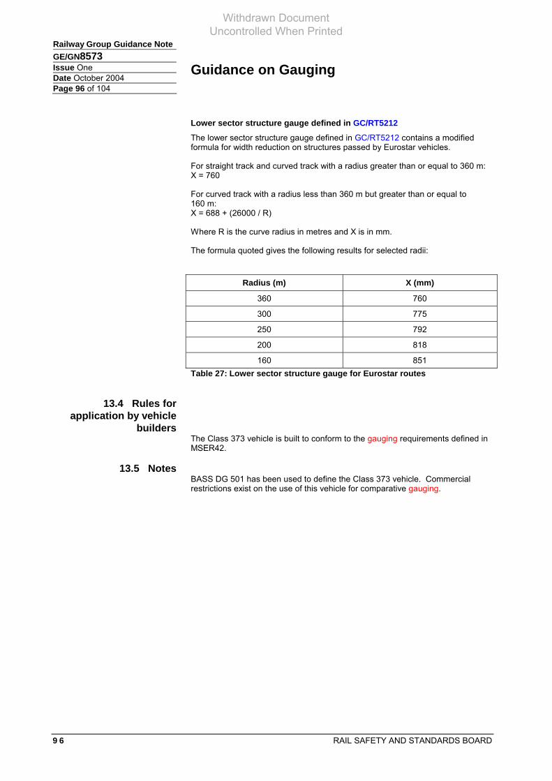
Guidance on Gauging
9 6 RAIL SAFETY AND STANDARDS BOARD
Railway Group Guidance Note GE/GN8573 Issue One Date October 2004 Page 96 of 104
Lower sector structure gauge defined in GC/RT5212
The lower sector structure gauge defined in GC/RT5212 contains a modified formula for width reduction on structures passed by Eurostar vehicles.
For straight track and curved track with a radius greater than or equal to 360 m: X = 760
For curved track with a radius less than 360 m but greater than or equal to 160 m: X = 688 + (26000 / R)
Where R is the curve radius in metres and X is in mm.
The formula quoted gives the following results for selected radii:
Radius (m) X (mm)
360 760
300 775
250 792
200 818
160 851 Table 27: Lower sector structure gauge for Eurostar routes
13.4 Rules for application by vehicle
builders The Class 373 vehicle is built to conform to the gauging requirements defined in MSER42.
13.5 Notes BASS DG 501 has been used to define the Class 373 vehicle. Commercial restrictions exist on the use of this vehicle for comparative gauging.
Withdrawn Document Uncontrolled When Printed

Guidance on Gauging
RAIL SAFETY AND STANDARDS BOARD 9 7
Railway Group Guidance NoteGE/GN8573 Issue One Date October 2004 Page 97 of 104
Appendix 14 Structure profile measurement accuracy – example form
Structure Profile Measurement Accuracy Form Page One
General Candidate system:
Date:
Description of measuring principle:
Description of rail location principle:
Description of positioning system:
Date:
Locational datum defined by (measuring system):
Locational datum measurement accuracy standard deviation (mm)
Datum point measuring system:
Datum point measuring system accuracy standard deviation (mm):
Notes:
Locational accuracy is the maximum error in positioning the vehicle that may develop between synchronisations of the distance measured by the vehicle and the true distance travelled. The latter may not correspond to the distances marked on the railway network (for example mileposts). The measurement should be on a range of normal track geometries if this may affect the results. The measuring method used to determine the true distance travelled should be stated, together with its accuracy, if known.
Measurement accuracy should be established with reference to a series of datum points distributed across the potential measuring area. At least 10 points should be used. These should be measured using an accurate measuring system, of stated accuracy.
The datum points should be measured as accurately as possible, the measuring method described, and the accuracy (defined by this methodology) should be stated, if known.
Withdrawn Document Uncontrolled When Printed
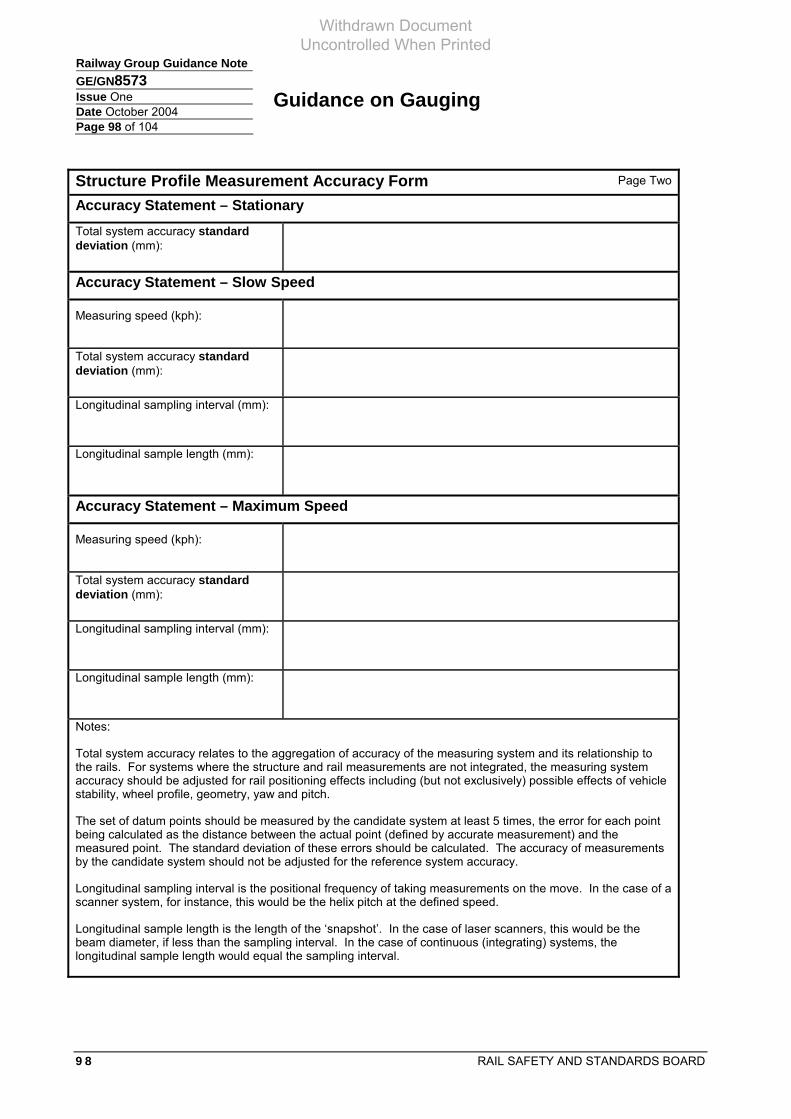
Guidance on Gauging
9 8 RAIL SAFETY AND STANDARDS BOARD
Railway Group Guidance Note GE/GN8573 Issue One Date October 2004 Page 98 of 104
Structure Profile Measurement Accuracy Form Page Two
Accuracy Statement – Stationary Total system accuracy standard deviation (mm):
Accuracy Statement – Slow Speed
Measuring speed (kph):
Total system accuracy standard deviation (mm):
Longitudinal sampling interval (mm):
Longitudinal sample length (mm):
Accuracy Statement – Maximum Speed
Measuring speed (kph):
Total system accuracy standard deviation (mm):
Longitudinal sampling interval (mm):
Longitudinal sample length (mm):
Notes:
Total system accuracy relates to the aggregation of accuracy of the measuring system and its relationship to the rails. For systems where the structure and rail measurements are not integrated, the measuring system accuracy should be adjusted for rail positioning effects including (but not exclusively) possible effects of vehicle stability, wheel profile, geometry, yaw and pitch.
The set of datum points should be measured by the candidate system at least 5 times, the error for each point being calculated as the distance between the actual point (defined by accurate measurement) and the measured point. The standard deviation of these errors should be calculated. The accuracy of measurements by the candidate system should not be adjusted for the reference system accuracy.
Longitudinal sampling interval is the positional frequency of taking measurements on the move. In the case of a scanner system, for instance, this would be the helix pitch at the defined speed.
Longitudinal sample length is the length of the ‘snapshot’. In the case of laser scanners, this would be the beam diameter, if less than the sampling interval. In the case of continuous (integrating) systems, the longitudinal sample length would equal the sampling interval.
Withdrawn Document Uncontrolled When Printed

Guidance on Gauging
RAIL SAFETY AND STANDARDS BOARD 9 9
Railway Group Guidance NoteGE/GN8573 Issue One Date October 2004 Page 99 of 104
Appendix 15 Freight load unit heights and profile codes
15.1 Purpose The following table is included to facilitate the gauging of freight loads and flat wagons. The dimensions relate to Swapbody loads (‘S’ Coded) and ISO containers. It is important to note that nominal dimensions differ between these types of load.
Max edge Max edge Max. 'S' code for Max. 'S' code for Corresponding ISO height (H) height (H) 2550 mm wide 2551 to 2600 mm container height
(MM) (ft/inches) swapbody wide swapbody
2455 8' 03/4" S00 S330 2465 8' 1" S01 S331 2475 8' 11/2" S02 S332 2485 8' 2" S03 S333 2495 8' 21/4" S04 S334 2505 8' 23/4" S05 S335 2515 8' 3" S06 S336 8' 3" (2515) 2525 8' 31/2" S07 S337 2535 8' 33/4" S08 S338 2545 8' 41/4" S09 S339 2555 8' 41/2" S10 S340 2565 8' 5" S11 S341 2575 8' 51/2" S12 S342 2585 8' 53/4" S13 S343 8' 6" (2591) 2595 8' 61/4" S14 S344 2605 8' 63/4" S15 S345 2615 8' 7" S16 S346 2625 8' 71/2" S17 S347 2635 8' 73/4" S18 S348 2645 8' 81/4" S19 S349 2655 8' 81/2" S20 S350 2665 8' 9" S21 S351 8' 9" (2667) 2675 8' 91/2" S22 S352 2685 8' 93/4" S23 S353 2695 8' 101/4" S24 S354 2705 8' 101/2" S25 S355 2715 8' 11" S26 S356 2725 8' 111/4" S27 S357 2735 8' 113/4" S28 S358 9' (2743) 2745 9' 01/4" S29 S359 2755 9' 01/2" S30 S360 2765 9' 1" S31 S361 2775 9' 11/4" S32 S362 2785 9' 13/4" S33 S363 2795 9' 2" S34 S364 2805 9' 21/2" S35 S365
Table 28: Freight load dimensions
Withdrawn Document Uncontrolled When Printed

Guidance on Gauging
1 0 0 RAIL SAFETY AND STANDARDS BOARD
Railway Group Guidance Note GE/GN8573 Issue One Date October 2004 Page 100 of 104
2815 9' 3" S36 S366 2825 9' 31/4" S37 S367 2835 9' 33/4" S38 S368 2845 9'4" S39 S369 2855 9' 41/2" S40 S370 2865 9' 5" S41 S371 2875 9' 51/4" S42 S372 2885 9' 53/4" S43 S373 2895 9' 6" S44 S374 9' 6" (2896) 2905 9' 61/2" S45 S375 2915 9' 63/4" S46 S376 2925 9' 71/4" S47 S377 2935 9' 73/4" S48 S378 2945 9' 8" S49 S379 2955 9' 81/2" S50 S380 2965 9' 83/4" S51 S381 2975 9' 91/4" S52 S382 2985 9' 91/2" S53 S383 2995 9' 10" S54 S384 3005 9' 101/2" S55 S385 3015 9' 103/4" S56 S386 3025 9' 111/4" S57 S387 3035 9' 111/2" S58 S388 3045 10' 0" S59 S389 10' (3048) 3055 10' 01/4" S60 S390 3065 10' 01/2" S61 S391 3075 10' 1" S62 S392 3085 10' 11/2" S63 S393 3095 10' 13/4" S64 S394 3105 10' 21/4" S65 S395 3115 10' 21/2" S66 S396 3125 10' 3" S67 S397
Table 28: Freight load dimensions (continued)
Withdrawn Document Uncontrolled When Printed

Guidance on Gauging
RAIL SAFETY AND STANDARDS BOARD 1 0 1
Railway Group Guidance NoteGE/GN8573 Issue One Date October 2004 Page 101 of 104
Appendix 16 Structure gauge for areas close to the plane of the rails This appendix originally appeared as Appendix B in GE/RT8029 issue 1 (now withdrawn).
This appendix is referenced in section K5.1 of this document.
Note A For lines electrified on the fourth rail system the fourth rail equipment extends to 40 mm above plane of the rails. On other lines equipment close to the centre line of the track shall not extend more than 25 mm above plane of the rails.
General notes: Except for that area designated for wheel flanges, locations below the plane of the rails are available for infrastructure.
Some major structures may have arrangements, particularly derailment protection (guard) rails, which do not conform to this appendix.
Area for check rails.
Area for dwarf signals, bridge girders, and other lineside equipment (conductor rail equipment, such as hook switches, is also permitted to utilise this area)
Area for wheel flanges.
Area for guard rails, (except where trains fitted with non-retractable shoes for electric current collection operate).
Area for conductor rail equipment, guard boards and APC magnets.
For train warning equipment and fourth rail only (Note A)
40
54
25
730
38
140 140
318 99
6440
Centreline of track
110
240
Running edge
All dimensions in millimetres
Plane of the rails
Withdrawn Document Uncontrolled When Printed

Guidance on Gauging
1 0 2 RAIL SAFETY AND STANDARDS BOARD
Railway Group Guidance Note GE/GN8573 Issue One Date October 2004 Page 102 of 104
Lines fitted with trainstop equipment (for example, Mersey Rail; joint running with London Underground Limited) have equipment which is outside the gauge when in the raised position. RGS GE/RT8018 contains details of trainstops, that is to say the position which causes the brakes to be applied.
Withdrawn Document Uncontrolled When Printed

Guidance on Gauging
RAIL SAFETY AND STANDARDS BOARD 1 0 3
Railway Group Guidance NoteGE/GN8573 Issue One Date October 2004 Page 103 of 104
References The Railway Group Standards Code
Railway Group Standards and other Railway Group Documents GC/RT5203 Infrastructure Requirements for Personal Safety in Respect of Clearances and
Access
GC/RT5021 Track System Requirements
GC/RT5110 Design Requirements for Structures
GC/RT5204 Structure Gauging and Clearances (withdrawn document)
GC/RT5212 Requirements for Defining and Maintaining Clearances
GC/RC5510 Recommendations for the Design of Bridges
GE/RT8006 Interface between Rail Vehicle Weights and Underline Bridges
GE/RT8270 Route Acceptance of Rail Vehicles including changes in Operation on Infrastructure
GE/RT8025 Electrical Protective Provisions for Electrified Lines
GE/RT8029 Management of Clearances and Gauging (withdrawn document)
GE/RT8034 Maintenance of Signal Visibility
GI/RT7003 Management of Construction Work in the Operational Railway Environment
GI/RT7014 Infrastructure Requirements at Stations
GI/RT7016 Interface between Station platforms, Track and Trains
GK/RT0037 Signal Positioning and Visibility
GM/RT2000 Engineering Acceptance of Rail Vehicles
GM/RT2100 Structural requirements for Railway Vehicles
GM/RT2149 Requirements for Defining and Maintaining the Size of Railway Vehicles (Issue 3)
GM/RT2456 Structural Requirements for Windsreens and Windows on Railway Vehicles
GM/RT2457 Structural Requirements for Doors and Gangways on Railway Vehicles
The Catalogue of Railway Group Standards and the Railway Group Standards CD-ROM give the current issue number and status of documents published by RSSB. This information is also available from www.rssb.co.uk.
Other References Derivation of a design Loading Gauge below 1089mm ARL, Report
ENG/TR/97/072, Author David Hatt, Bombardier Transportation Ltd, Derby
UIC Gauging Principles, Author D M Johnson, Laser Rail Ltd
BASS DG 501 British Rail Bogie and Suspension Section Design Guide number 501, ‘Kinematic Envelope and Curve Overthrow Calculations’
TME 587 British Rail drawing B2-CO-8700472 Dynamic Swept Envelope TME587 Design Curve Radius 160m issue D 1990
PO/CL527 British Rail DM&EE drawing 1990
PO/CL548 British Rail T&RS drawing 1993
L-A1-1806 British Rail CM&EE drawing 1970
Withdrawn Document Uncontrolled When Printed

Guidance on Gauging
1 0 4 RAIL SAFETY AND STANDARDS BOARD
Railway Group Guidance Note GE/GN8573 Issue One Date October 2004 Page 104 of 104
HS(G)153/1 Railway Safety Principles and Guidance Part 1, Health and Safety Executive (HM Railway Inspectorate)
HS(G)153/2 Railway Safety Principles and Guidance Part 2, Section A, Guidance on the Infrastructure, Health and Safety Executive (HM Railway Inspectorate)
Technical specification for interoperability relating to the energy subsystem of the trans-European high-speed rail system referred to in Article 6(1) of Directive 96/48/EC [‘High Speed Energy TSI’]
Technical specification for interoperability relating to the infrastructure subsystem of the trans-European high-speed rail system referred to in Article 6(1) of Council Directive 96/48/EC [‘High Speed Infrastructure TSI’]
Technical specification for interoperability relating to the rolling stock subsystem of the trans-European high-speed rail system referred to in Article 6(1) of Directive 96/48/EC [‘High Speed Rolling Stock TSI’]
MSER 42 General Gauging Procedure for Class 373 Trains, Mechanical Systems Engineer Report no 42 Issue 1 1995
UIC 503 Continental wagons running in Great Britain - General conditions (reference profile, axle-load, etc) for the acceptance, in international traffic with Great-Britain, of 2-axle and bogies wagons registered with other UIC Railways
UIC 505-1 Railway transport stock - Rolling stock construction gauge
UIC 505-4 Effects of the application of the kinematic gauges defined in the 505 series of leaflets on the positioning of structures in relation to the tracks and of the tracks in relation to each other
UIC 505-5 Basic conditions common to Leaflets 505-1 to 505-4 - Notes on the preparation and provisions of these leaflets
UIC 506 Rules governing application of the enlarged GA, GB and GC gauges
C1 drawings
C1 (Appendix A) drawings
Withdrawn Document Uncontrolled When Printed