guidance note - flow measurement, flow assurance, flow ... · pdf fileguidance note effect of...
TRANSCRIPT

GUIDANCE NOTE
Effect of Control Valve Noise onUltrasonic Gas Flow Meters
www.tuvnel.com

Introduction
This document provides guidance on the effect of control valve ultrasonic noise on ultrasonic meters. The guidance is aimed at the operators of gas ultrasonic meters and the designers of metering systems that include gas ultrasonic meters. This guide is primarily interested in the noise generated by control / throttling valves and pressure regulators etc. However it has been noted that other items of in-line equipment, (under certain circumstances) can, generate ultrasonic noise to a level high enough to affect ultrasonic meters. These include flow conditioners and filters such as a ‘Witches’ Hat’ used during pipeline commissioning.
Effects of Ultrasonic Noise on an Ultrasonic Meter
Transit Time Ultrasonic Meters
Transit time ultrasonic meters operate by transmitting short duration ultrasonic pulses through the flow and measuring the time that it takes the pulse to go from the transmitter to receiver i.e. the transit time. The gas velocity can be determined by measuring the difference in upstream and downstream transit times; since this time is directly proportional to the velocity of flow.
Figure 1 Transit Time Ultrasonic Flow Meter
In order to measure the transit time the meter’s electronics must be able to detect the arrival of the ultrasonic pulse at the receiving transducer. Ultrasonic noise at the meter’s transmitting frequency can make detection of the received signal difficult, potentially causing the meter to either misread or fail
Transducer Operating Frequency
Ultrasonic transducers generally operate at a specific resonant frequency (Fo). Figure 2a shows a typical frequency-response curve for an ultrasonic transducer. The transducer transmits and receives ultrasound only over those frequencies. Hence, when operating as an ultrasonic receiver, it acts like a band pass filter only responding to frequencies about the operating frequency. In this way the ultrasonic meter is only susceptible to noise at the transducer’s resonant frequency. Control valves generate a broad spectrum of noise; if this spectrum overlaps the transducer frequency as shown in Figure 2a then, depending on the amplitude of the
noise, the meter may be affected. If the signal-to-noise ratio drops by enough then the meter will fail to locate the arrival of the signal and fail to give a reading unless further more sophisticated signal-processing methods are employed. Figure 2b shows how, in principle, the control-valve noise can be avoided by increasing the transducer frequency.
Figure 2 Influence of Transducer Operating Frequency
Literature reveals that many meters operate at, or about 100 kHz, which is in the range that throttle valves can potentially emit. In many cases, raising this operating frequency to 200 kHz or above moves the signal away from the main noise frequencies, thus improving the noise immunity of the meter.
It should, however, be noted that higher transducer frequencies inevitably lead to lower signal amplitudes due to poorer transmission between the solid transducer and the flowing gas. This in turn could have consequences for meter operation if the received signal amplitude is too low.
Signal Processing Techniques
Signal averaging or ‘stacking’ is a very effective way of reducing unwanted random noise. The technique essentially stores successive arrival window traces and then averages these. Since the noise is random, its magnitude is diminished by the square root of the stack size (the number of traces that have been averaged) whereas the signal, which is constant in the traces remains. The disadvantages to this technique are two-fold. Firstly, the response time of the meter is reduced, as a function of the stack size. Secondly, any rapid change in flow rate could potentially cause the meter to misread or fail due to movement of the signal during successive traces, leading to signal degradation when the averaging is applied.
Another technique that might be expected to be effective at locating a transmitted signal in noisy conditions is digital correlation. As shown in Figure 3 this technique involves applying a digital copy of the transmitted signal and the received signal to a digital correlation algorithm. The time at which these correlate to the highest degree, i.e. the correlation function reaches a maximum, is taken as the signal arrival time.
Figure 3 Concept of Digital Correlation Technique
Effect of Control Valve Noise on Ultrasonic Gas Flow Meters
Design Considerations
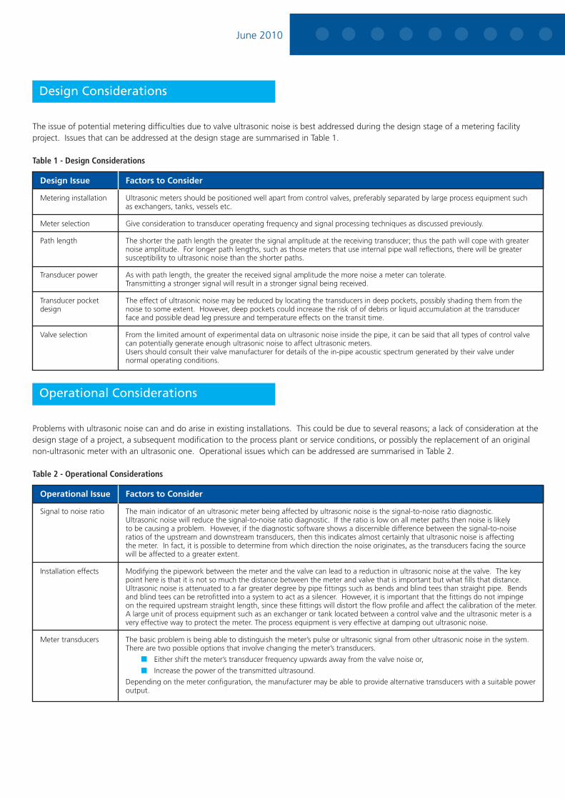
The issue of potential metering difficulties due to valve ultrasonic noise is best addressed during the design stage of a metering facility project. Issues that can be addressed at the design stage are summarised in Table 1.
Table 1 - Design Considerations
Design Issue Factors to Consider
Metering installation Ultrasonic meters should be positioned well apart from control valves, preferably separated by large process equipment such as exchangers, tanks, vessels etc.
Meter selection Give consideration to transducer operating frequency and signal processing techniques as discussed previously.
Path length The shorter the path length the greater the signal amplitude at the receiving transducer; thus the path will cope with greater noise amplitude. For longer path lengths, such as those meters that use internal pipe wall reflections, there will be greater susceptibility to ultrasonic noise than the shorter paths.
Transducer power As with path length, the greater the received signal amplitude the more noise a meter can tolerate. Transmitting a stronger signal will result in a stronger signal being received.
Transducer pocket The effect of ultrasonic noise may be reduced by locating the transducers in deep pockets, possibly shading them from the design noise to some extent. However, deep pockets could increase the risk of of debris or liquid accumulation at the transducer face and possible dead leg pressure and temperature effects on the transit time.
Valve selection From the limited amount of experimental data on ultrasonic noise inside the pipe, it can be said that all types of control valve can potentially generate enough ultrasonic noise to affect ultrasonic meters. Users should consult their valve manufacturer for details of the in-pipe acoustic spectrum generated by their valve under normal operating conditions.
Operational Considerations
Problems with ultrasonic noise can and do arise in existing installations. This could be due to several reasons; a lack of consideration at the design stage of a project, a subsequent modification to the process plant or service conditions, or possibly the replacement of an original non-ultrasonic meter with an ultrasonic one. Operational issues which can be addressed are summarised in Table 2.
Table 2 - Operational Considerations
Operational Issue Factors to Consider
Signal to noise ratio The main indicator of an ultrasonic meter being affected by ultrasonic noise is the signal-to-noise ratio diagnostic. Ultrasonic noise will reduce the signal-to-noise ratio diagnostic. If the ratio is low on all meter paths then noise is likely to be causing a problem. However, if the diagnostic software shows a discernible difference between the signal-to-noise ratios of the upstream and downstream transducers, then this indicates almost certainly that ultrasonic noise is affecting the meter. In fact, it is possible to determine from which direction the noise originates, as the transducers facing the source will be affected to a greater extent.
Installation effects Modifying the pipework between the meter and the valve can lead to a reduction in ultrasonic noise at the valve. The key point here is that it is not so much the distance between the meter and valve that is important but what fills that distance. Ultrasonic noise is attenuated to a far greater degree by pipe fittings such as bends and blind tees than straight pipe. Bends and blind tees can be retrofitted into a system to act as a silencer. However, it is important that the fittings do not impinge on the required upstream straight length, since these fittings will distort the flow profile and affect the calibration of the meter. A large unit of process equipment such as an exchanger or tank located between a control valve and the ultrasonic meter is a very effective way to protect the meter. The process equipment is very effective at damping out ultrasonic noise.
Meter transducers The basic problem is being able to distinguish the meter’s pulse or ultrasonic signal from other ultrasonic noise in the system. There are two possible options that involve changing the meter’s transducers.
Either shift the meter’s transducer frequency upwards away from the valve noise or,
Increase the power of the transmitted ultrasound.
Depending on the meter configuration, the manufacturer may be able to provide alternative transducers with a suitable power output.
June 2010
The purpose of this Guidance Note is to provide, in condensed form, information on measurement methods and technologies. It was produced as part of the UK Government’s National Measurement System.
For further information, contact:
TUV NEL, East Kilbride, GLASGOW, G75 0QF, UK
Tel: + 44 (0) 1355 220222 Email: [email protected]
www.tuvnel.com
© TUV NEL Ltd 2010
Re-issued 2010This publication is to provide outline information only which (unless agreed by TUV NEL in writing) may not be reproduced for any purpose or form part of any order or contract or be regarded as representation relating to products or services concerned.
Further Reading
Effect of Control Valve Noise on Multi-path Ultrasonic Gas Flow Meters – Guidance to Meter Users. Report 2003/240. TUV NEL Ltd. East Kilbride, Glasgow.
BS EN 60534-8-3 Ed.2:2000, (Harmonised from IEC 60534-8-3). Industrial Process Control Valves - Part 8-3: Noise Considerations - Control Valve Aerodynamic Noise Prediction Method. October 2000.
Vermeulen, M.J.M., DeBoer and G., Bowen, J. A Model for Estimation of the Ultrasonic Acoustic Noise Level Emitted by Pressure Regulating Valves and its Influence on Ultrasonic Flow Meters. Instromet. 2000
Bruggeman, J.C., Hopmans, L.J.M., Blijie, C.J.M. and Van-Veghal, H. A Comparison of Prediction Methods for Valve noise with Experimental Results. Proceedings of Internoise 1996, Liverpool.
van Bloemendaal, K., Sloet, G.H., Hosten, B., Brassier, P. and Vulovic, F. Ultrasonic Meters and Noise. Task 4 of the Second GERG Project on Ultrasonic Meters, GERG, 1998.
Stoll, P., Slawig, H., Muller, C, de Boer, G. and Vermeulen, M. Ultrasonic Noise Characteristics of Valves with Respect to Ultrasonic Gas Flow Meters. 16th North Sea Flow Measurement Workshop, paper 7, Scotland, October 1998
Effect of Control Valve Noise on Ultrasonic Gas Flow Meters
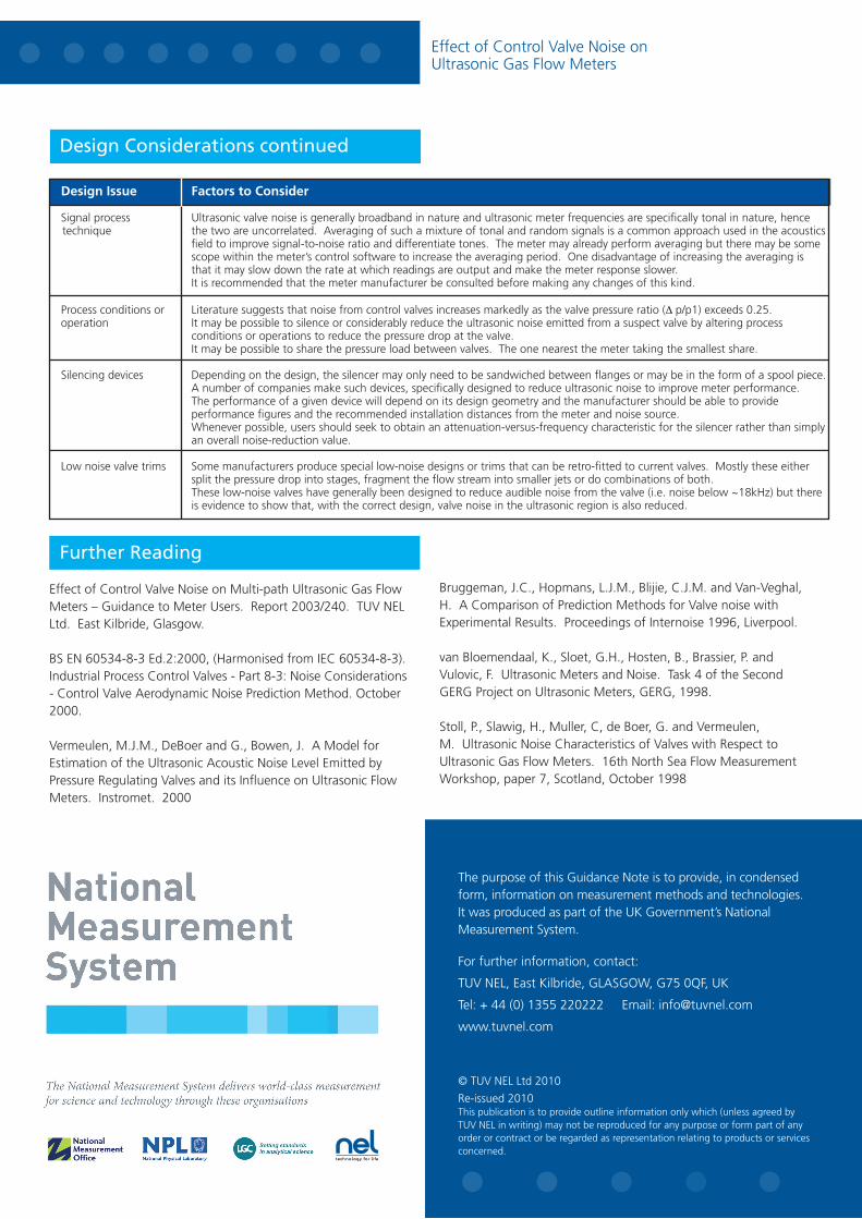
Design Considerations continued
Design Issue Factors to Consider
Signal process Ultrasonic valve noise is generally broadband in nature and ultrasonic meter frequencies are specifically tonal in nature, hence technique the two are uncorrelated. Averaging of such a mixture of tonal and random signals is a common approach used in the acoustics field to improve signal-to-noise ratio and differentiate tones. The meter may already perform averaging but there may be some scope within the meter’s control software to increase the averaging period. One disadvantage of increasing the averaging is that it may slow down the rate at which readings are output and make the meter response slower. It is recommended that the meter manufacturer be consulted before making any changes of this kind.
Process conditions or Literature suggests that noise from control valves increases markedly as the valve pressure ratio (D p/p1) exceeds 0.25. operation It may be possible to silence or considerably reduce the ultrasonic noise emitted from a suspect valve by altering process conditions or operations to reduce the pressure drop at the valve. It may be possible to share the pressure load between valves. The one nearest the meter taking the smallest share.
Silencing devices Depending on the design, the silencer may only need to be sandwiched between flanges or may be in the form of a spool piece. A number of companies make such devices, specifically designed to reduce ultrasonic noise to improve meter performance. The performance of a given device will depend on its design geometry and the manufacturer should be able to provide performance figures and the recommended installation distances from the meter and noise source. Whenever possible, users should seek to obtain an attenuation-versus-frequency characteristic for the silencer rather than simply an overall noise-reduction value.
Low noise valve trims Some manufacturers produce special low-noise designs or trims that can be retro-fitted to current valves. Mostly these either split the pressure drop into stages, fragment the flow stream into smaller jets or do combinations of both. These low-noise valves have generally been designed to reduce audible noise from the valve (i.e. noise below ~18kHz) but there is evidence to show that, with the correct design, valve noise in the ultrasonic region is also reduced.