guidance for developing and conducting annual dp trials ...c.ymcdn.com/sites/ · pdf...
TRANSCRIPT

Guidance for
Developing and Conducting
Annual DP Trials Programmes
for DP Vessels
IMCA M 190
June 2011
International MarineContractors Association
www.imca-int.com
AB

AB
The International Marine Contractors Association
(IMCA) is the international trade association
representing offshore, marine and underwater
engineering companies.
IMCA promotes improvements in quality, health, safety,
environmental and technical standards through the publication
of information notes, codes of practice and by other
appropriate means.
Members are self-regulating through the adoption of IMCA
guidelines as appropriate. They commit to act as responsible
members by following relevant guidelines and being willing to be
audited against compliance with them by their clients.
There are two core activities that relate to all members:
Competence & Training
Safety, Environment & Legislation
The Association is organised through four distinct divisions,
each covering a specific area of members‟ interests: Diving,
Marine, Offshore Survey, Remote Systems & ROV.
There are also five regional sections which facilitate work on
issues affecting members in their local geographic area –
Asia-Pacific, Central & North America, Europe & Africa, Middle
East & India and South America.
IMCA M 190
This document has been prepared on behalf of the Marine
Division Management Committee by GL Noble Denton.
www.imca-int.com/marine
The information contained herein is given for guidance only and endeavours to reflect best industry practice. For the avoidance of doubt no legal liability shall
attach to any guidance and/or recommendation and/or statement herein contained.
© 2011 IMCA – International Marine Contractors Association

Guidance for Developing and Conducting Annual DP Trials
Programmes for DP Vessels
IMCA M 190 – June 2011
1 Introduction ........................................................................................................... 1
1.1 Scope ......................................................................................................................................................................... 1
1.2 Limitations ................................................................................................................................................................ 1
1.3 Background .............................................................................................................................................................. 1
1.4 Purpose of the Guidance ...................................................................................................................................... 2
2 Glossary .................................................................................................................. 3
3 Existing Industry and Statutory Requirements for Annual DP Trials ............. 5
3.1 IMO ............................................................................................................................................................................ 5
3.2 IMCA ......................................................................................................................................................................... 5
3.3 Flag/Coastal State ................................................................................................................................................... 6
3.4 Classification Societies .......................................................................................................................................... 6
3.5 Clients .................................................................................................................................................................... 11
4 Development of the Trials Programme ............................................................ 12
4.1 Difference Between an Annual DP Trial and an FMEA Proving Trial .................................................... 12
4.2 Benefits of Annual DP Trials ............................................................................................................................ 12
4.3 Responsibility for Developing the Trials Programme ................................................................................ 12
4.4 Competence of Persons Developing the Trials Programme ................................................................... 12
4.5 Information Necessary to Develop the Trials Programme ...................................................................... 13
4.6 Lifetime Management of the FMEA ................................................................................................................. 13
4.7 Developing the Trials Programme .................................................................................................................. 14
4.8 What Types of Test may not Normally Need to be Carried Out? ....................................................... 18
4.9 What Tests can Meaningfully be Carried Out Alongside or not „On DP‟? .......................................... 19
4.10 Review of Planned Maintenance or Survey Records in Lieu of Testing ................................................ 20
4.11 Do All Tests Have to be Carried Out Every Year? ................................................................................... 20
4.12 Testing for Different Equipment Classes ...................................................................................................... 21
4.13 Other Aspects of Vessel Assurance Carried Out During the Annual DP Trials................................ 22
5 Conduct of the Trials .......................................................................................... 24
5.1 Scheduling of Trials ............................................................................................................................................. 24
5.2 Planning for Trials ................................................................................................................................................ 24
5.3 Independent Witnesses ..................................................................................................................................... 24
5.4 Responsibility for Trials ..................................................................................................................................... 24
5.5 Trials Co-ordinators ........................................................................................................................................... 25
5.6 Attendance of Vendors‟ Representatives at Annual Trials ....................................................................... 25
5.7 Attendance of Client Representatives During Trials ................................................................................. 25
5.8 Liaison with Classification Society................................................................................................................... 26
5.9 Safety During Trials, Including Working Hours........................................................................................... 26

5.10 Other Requirements During Testing ............................................................................................................. 27
5.11 Practical Guidance on Carrying Out Tests and Recording the Results ................................................ 27
5.12 Generating Findings from Trials Results........................................................................................................ 33
5.13 Actions Following Completion of the Trials ................................................................................................ 35
6 Format of the Trials Report ............................................................................... 37
6.1 Description of Essential Information to be Included in the Final Report ............................................. 37
6.2 Information to be Included on Test Sheets .................................................................................................. 37
7 References ............................................................................................................ 39
Appendices
1. Example Annual DP Trials Report .................................................................... 40
2. Example Trials Summary Letter ....................................................................... 57
3. Example Findings List ......................................................................................... 58

IMCA M 190 1
1 Introduction
1.1 Scope
This document describes the development, conduct and management of annual DP trials programmes
for all types of vessels equipped with DP systems meeting the requirements of International Maritime
Organization (IMO) equipment classes 1, 2 or 3. IMCA M 191 – Guidelines for annual DP trials for DP
mobile offshore drilling units – sets out a programme of continuous trials throughout the year.
However, much of the guidance provided in this document will also be applicable to mobile offshore
drilling units (MODUs).
A dynamically positioned vessel (DP vessel) means a unit or a vessel which automatically maintains its
position (fixed location or pre-determined track) by means of thruster force.
Dynamic positioning system (DP system) means the complete installation necessary for dynamically
positioning a vessel comprising the following sub-systems:
power system – including prime movers with necessary auxiliary systems including piping,
generators, switchboards and distribution system (i.e. cabling and cable routing);
thruster system – including thrusters with drive units and necessary auxiliary systems including
piping, main propellers and rudders if these are under control of the DP system, thruster control
electronics, manual thruster controls and all associated cabling and cable routing;
DP control system – including computer system/joystick system, sensor system, display system
(operator panels), position reference system and all associated cabling and cable routing.
1.2 Limitations
Nothing in this guidance is intended to replace or contradict the various requirements for initial or
periodical tests of the DP system as may be required by the vessel‟s flag state authority or
classification society.
1.3 Background
In the 1980s, DP systems onboard vessels were often tested many times during a year and the time
required for this frequent and repetitious testing was costly and inconvenient for both vessel owners
and their clients. In addition, the frequent testing increased the risk of equipment damage.
In 1991, vessel owner representatives met oil company and government representatives to discuss and
rationalise the auditing and testing of dynamically positioned vessels. This resulted in the development
of DPVOA guideline 112 UKOOA Part 2 – Guidelines for auditing vessels with dynamic positioning systems
– which was published in 1993. The rationalisation process continued and was enhanced with the
production of IMO Maritime Safety Committee (MSC) Circular 645 (IMO MSC/Circ. 645) which was
adopted in 1994. This IMO circular requires annual testing of all important systems and components
of a DP system to ensure that it is maintained in good working order and to document the vessel‟s
ability to keep position after single failures associated with the assigned equipment class.
Since then, the concept of an annual DP trial supplemented by much shorter field arrival trials has
been recommended by IMCA as a means of demonstrating that the vessel is fit to carry out DP
operations appropriate to her DP equipment class.
In 1997, IMCA produced IMCA M 139 – Standard report for DP vessels annual trials. This template has
been widely accepted and is used with few modifications by the vast majority of vessel operators who
choose to adopt IMCA guidance. IMCA M 139 has now been updated to reflect the guidance in this
document.
Annual DP trials are only one part of the overall process used by clients to audit and accept DP
vessels for various scopes of work. Guidance on the overall process is described in 112 UKOOA
Part 2.
All of the major classification societies, as well as IMO, have requirements for annual surveys or tests
of the DP system; however, guidance as to the specific content of such surveys varies in its detail.
2 IMCA M 190
1.4 Purpose of the Guidance
This guidance is intended to assist vessel operators in the development of a suitable annual DP trials
programme which is consistent in content to similar vessels, more effectively demonstrates the
vessel‟s ability to maintain position following identified single failures, demonstrates that the DP system
is in good working order, contributes to the effective management of the failure modes and effects
analysis (FMEA) and ensures best use of the time available for DP system tests by more effectively
identifying items which do not need to be tested every year or whose reliability can be demonstrated
by other means.
This guidance is not intended to provide a generic list of tests which should be carried out at annual
trials. The guidance will assist in the development of a vessel specific trials programme based around
the key elements of a fault tolerant system which are: performance; protection; and detection.
This document is not intended to replace 112 UKOOA Part 2 in its entirety. The relevant sections of
that document which have been updated by this guidance are:
Preface – Definitions – Competent Auditor;
Section 3.3 – Annual Trials;
Section 4.2 – Tests and Trials;
Section 5.1 – Auditors for Annual Trials.

IMCA M 190 3
2 Glossary
ABS American Bureau of Shipping
ac Alternating current
AVR Automatic voltage regulator
BV Bureau Veritas
CMID Common Marine Inspection Document
CPP Controllable pitch propeller
dc Direct current
DGPS Differential Global Positioning System
DNV Det Norske Veritas
DoT Department of Transport
DP Dynamic positioning
DPO Dynamic positioning operator
DPVOA DP Vessel Owners Association
ECR Engine control room
ESD Emergency shutdown/Emergency shutdown and disconnect
ETO Electrotechnical officer
F&G Fire and gas
FMEA Failure modes and effects analysis
FMECA Failure modes, effects and criticality analysis
FSVAD Flag state verification and acceptance document
FW Fresh water
GL Germanischer Lloyd
GPS Global Positioning System
HSE Health and Safety Executive (UK)
IMCA International Marine Contractors Association
IMO International Maritime Organization
kVAr Kilovolt Ampere reactive
kW Kilowatt
LED Light emitting diode
LRS Lloyd‟s Register of Shipping
MODU Mobile offshore drilling unit
MRU Motion reference unit
MSC Maritime Safety Committee (of the IMO)
NO/NC Normally open/normally closed
OCIMF Oil Companies International Marine Forum
OVID Offshore Vessel Inspection Database
PMS Planned maintenance system
PRS Position reference system
ROV Remotely operated vehicle
RPM Revolutions per minute
SIRE Ship Inspection Report Programme
STCW Standards for Training Certification and Watchkeeping

4 IMCA M 190
SW Sea water
UKOOA United Kingdom Offshore Operators Association (now Oil & Gas UK)
UPS Uninterruptible power supply
UTM Universal transverse mercator
VMS Vessel management system
WCF Worst case failure
WCFDI Worst case failure design intent
IMCA M 190 5
3 Existing Industry and Statutory Requirements for Annual DP Trials
3.1 IMO
IMO Guidelines for vessels with dynamic positioning systems are contained within the annex to IMO
MSC/Circ. 645 which was issued in June 1994.
The guidelines are still relevant today and form the basis of the major classification societies‟ rules
regarding DP vessels.
Section 5 of the guidelines discusses surveys and testing. There is a requirement for „initial survey‟,
„periodical survey at intervals not exceeding five years‟ and „annual survey‟.
For the purposes of this document, the descriptions of the periodical survey and annual survey are
relevant.
“Annual survey should be carried out within three months before or after each anniversary date of the
initial survey. The annual survey should ensure that the DP system has been maintained in accordance
with applicable parts of the guidelines and is in good working order. Further, an annual test of all
important systems and components should be carried out to document the ability of the DP vessel to keep
position after single failures associated with the assigned equipment class.”
“Periodical survey at intervals not exceeding five years to ensure full compliance with the applicable parts
of the guidelines. A complete test should be carried out as required in 5.1.1.1.”
The complete test referred to above as described in 5.1.1.1 is part of the initial survey and is
described as “a complete test of all systems and components and the ability to keep position after
single failures associated with the assigned equipment class”.
From the above it can be seen that the annual test covers „all important systems and components‟ and
that the five-yearly test requires „a complete test of all systems and components‟. There is no further
guidance regarding the difference between the two types of test or what constitutes an important
component.
3.2 IMCA
As discussed previously, 112 UKOOA, originally produced by a working group comprising the
UK Offshore Operators Association (UKOOA), the Dynamic Positioning Vessel Owners Association
(DPVOA), the UK Health and Safety Executive (HSE) and the UK Department of Transport (DoT), set
out IMCA‟s previous guidance on annual DP trials prior to the development of this document.
The extent of the guidance regarding the purpose and content of those trials is as follows:
“The purpose of the annual trials is to test all fault and failure conditions important to DP safety to prove
that redundancy, protection and responses are correct.”
IMCA also produced IMCA M 139 in 1997 in order to standardise the presentation of the results of
annual trials. This format has been almost universally adopted by those vessel operators following
IMCA guidance.
IMCA M 182 – International guidelines for the safe operation of dynamically positioned offshore supply vessels
– was produced by a cross-industry working group including IMCA. The document was most recently
revised in 2009.
The guidance on annual trials contained within that document states that:
“The purpose of these (annual) trials is to ensure that the DP system has been maintained properly, is in
good working order and meets the requirements of its assigned DP class notation.”
The guidelines (in IMCA M 182) also discuss the scheduling and witnessing of the annual trials as
follows:
“Annual DP trials may be conducted as a single, separate event, or as part of a rolling test programme
over the year, possibly as part of the vessel‟s planned maintenance programme. The industry norm is for
the trials to be carried out as a single, separate event. Where the trials are held on this basis, owners
6 IMCA M 190
should ensure that they are witnessed by a third party. This could be an independent third party or any
competent person separate from the relevant operational team, such as the master or chief engineer of
another vessel, or an appropriate shore-based technical specialist. Where the trials are part of a rolling
test programme over the year, the owner should ensure that the trials and the results are subject to
independent scrutiny and approval.”
It should be borne in mind that the guidance contained in IMCA M 182 applies to supply vessels
carrying out supply operations involving the transfer of deck, dry bulk and liquid cargoes, or any other
marine surface operations such as, for example, anchor handling and supply to a pipelaying vessel.
It does not apply to supply vessels which may engage in other DP operations appropriate to their
equipment class such as ROV support, diving support or cable laying, for example. It may also be the
case that even for carrying out basic supply vessel operations, as described above, using DP, clients‟
own requirements may be that supply vessels conform to the industry norm of a single annual DP trial,
witnessed by an independent person or persons.
It is also relevant when considering the annual trials regime suggested by IMCA M 182 that IMO
MSC/Circ. 645 states that “when a vessel is assigned an equipment class this means that the DP vessel
is suitable for all types of DP operations within the assigned and lower equipment classes”.
IMCA has also produced IMCA M 191 – Guidelines for annual DP trials for DP mobile offshore drilling units.
As MODUs are outside the scope of this document, the content of IMCA M 191 is not discussed
further.
3.3 Flag/Coastal State
3.3.1 General Comment
IMO MSC/Circ. 645 invites member governments to bring the guidelines to the attention of
all bodies concerned and apply the guidelines to new vessels with dynamic positioning
systems constructed on or after 1 July 1994, compliance with the guidelines to be
documented by a flag state verification and acceptance document (FSVAD) for the dynamic
positioning system.
In practice, the flag states seem content to leave verification of DP systems to the
classification societies whose rules for DP vessels are chiefly based on the varying
requirements for the equipment classes 1, 2 and 3 described in IMO MSC/Circ. 645. It is
extremely rare to see an FSVAD issued to a DP vessel by the flag state.
3.4 Classification Societies
3.4.1 General
It is not the intention of this document to analyse or discuss the differing requirements for
the assignment of the various class notations relating to DP that may exist or may be
perceived to exist between the main classification societies. The purpose of this section is to
identify requirements for annual DP trials where they may exist. The tables illustrating the
various class notations and their correlation to IMO equipment classes are given for general
information only.
The latest issued rules have been consulted as being the best indicators of current industry
practice. It is accepted that older rules may apply to some vessels.

IMCA M 190 7
3.4.2 Correlation Between IMO Equipment Classes and Classification Society Notations
Table 1 illustrates the class notations which correspond to IMO equipment classes 1, 2 and 3.
IMO Equipment Class
DNV
ABS
LRS
BV
GL
1 DYNPOS-AUT
Or
DPS 1
DPS-1 DP (AM) DYNAPOS AM/AT DP 1
2 DYNPOS- AUTR
Or
DPS 2
DPS-2 DP (AA) DYNAPOS AM/AT R DP 2
3 DYNPOS- AUTRO
Or
DPS 3
DPS-3 DP (AAA) DYNAPOS AM/AT RS DP 3
Table 1 – Classification society DP notations
3.4.3 Det Norske Veritas (DNV)
The requirements for periodic testing of the DP system are contained within Part 7 of the
DNV Rules (Ships in Operation), Chapter 1, Survey Requirements.
Under the DNV survey regime, operators of vessels having notation AUTR, DPS 2, AUTRO
or DPS 3 have the option of undergoing a shorter annual survey and a complete five-yearly
survey, or having a complete survey every year for which the additional class notation A is
assigned, e.g. DYNPOS-AUTR(A) or DPS 2(A).
Guidance on the difference between an annual survey and a complete survey is given in Table
2:
Test Item Annual Survey Complete Survey
Document
review
Review of maintenance including changes
to hardware and software. Review of
FMEA updating
Review of maintenance including changes
to hardware and software. Review of
FMEA updating
Visual inspection
All equipment relevant for DP and not covered by main class
All equipment relevant for DP and not covered by main class
Functional
testing
Testing to verify that the DP system is
capable of positioning the vessel
(preferably during a sea trial but may be
done during regular operations), including:
proper operation (important modes)
important screen views
position and heading alarms
operator panel (night view, lamp test)
joysticks
thrusters (selectable)
PRS (selectable)
sensors (selectable)
Tested in all operational modes, including:
manual/joystick/IJS/DP
all PRSs (including accuracy)
all sensors (including accuracy)
simulation of failure modes to verify switching of modes, back-up systems
and alarms
Blackout
testing
None Failure of ac, dc and UPS switchboards
Failure
response
None Single failures of command and feedback
signals to thrusters
Failures of PRS and sensor inputs
Alarm
verification
Some alarms verified during functional
testing
Verify all required alarms
UPS Capacity to be tested including alarm for
loss of charger power
Capacity to be tested including alarm for
loss of charger power

8 IMCA M 190
Test Item Annual Survey Complete Survey
Emergency
stops
To be tested To be tested, including loop monitoring
Mode changes Functional test Functional and failure tests
Back-up DP Verify normal working condition Verify normal working condition and
repeat relevant failure tests
Special features Consequence analysis Consequence analysis
Blackout prevention
Dead reckoning
Table 2 – DNV requirements for annual and complete surveys
It is also noted that if the annual survey is carried out during regular operations rather than
during a dedicated sea trial, then certain tests may not necessarily be carried out if it is
deemed unsafe to do so. These tests include UPS battery endurance, emergency stops,
changeover to back-up DP system (for AUTRO) or all operational modes.
For complete surveys for DYNPOS-AUTR and AUTRO (i.e. IMO equipment classes 2 and 3)
then the required redundancy with respect to defined single failure modes shall be verified by
redundancy testing.
From the information presented above, it can be seen that an annual survey is primarily a
functional demonstration that the DP system is operational. Other than some normal
operational alarm conditions, there is no requirement to fail components of the DP system.
Tests involving failure of key components of the DP system are carried out every five years
during the complete survey.
3.4.4 Lloyd’s Register of Shipping (LRS)
The requirements for periodic testing of the DP system are contained within Part 1 of the
LRS Rules and Regulations (Regulations), Chapter 2 (Classification Regulations) and Chapter 3
(Periodical Survey Regulations).
Annual surveys – “For ships fitted with a classed dynamic positioning system and/or classed thruster
assisted positional mooring system, the control system and associated machinery items are to be
generally examined and tested under operating conditions to an approved test schedule.”
Special surveys, not exceeding five years – “On vessels fitted with a classed dynamic positioning
system, the control system and associated machinery items are to be examined and tested to
demonstrate that they are in good working order.”
3.4.5 American Bureau of Shipping (ABS)
The requirements for periodic testing of the DP system are contained within Part 7 of the
ABS Rules (Rules for Survey After Construction), Chapter 9 (Survey Requirements for
Additional Systems and Services), Section 6 (Thrusters and Dynamic Positioning System).
The rules state the requirements for the content of annual survey and special periodical
surveys (five years).
The contents of an annual survey are summarised as follows:
the vessel is to be operated for a duration of at least two hours to demonstrate that the
DP system has been maintained properly and is in good working order. The operational
testing does not include the complete performance tests to demonstrate the levels of
redundancy established in the FMEA;
control system including thruster emergency stops, position keeping redundancy, alarms
and instrumentation are to be generally examined;
wind sensors and gyros to be generally examined and functionality confirmed;
automatic transfer of control between automatic control systems following failure of the
on line system to be tested including the back-up control system for DPS-3 notation.

IMCA M 190 9
Operation of the manual control system following complete failure of the automatic
systems to be tested;
individual, manual thruster controls to be tested;
the following indicators are to be operational at the DP control station as applicable:
CPP pitch
thruster RPM
thruster direction
thruster motor temperature
thrust motor short circuit
thrust motor exciter power available
thrust motor supply power available
circuit breaker status
bus bar current and power levels
high power consumers current levels
vessel target and present position and heading
wind speed and direction
selected reference systems
thruster location (pictorial)
percentage thrust
available thrusters on standby
position information from individual PRSs;
the following alarms are to be operational at the DP control station as applicable:
engine lube oil – low pressure
engine coolant – high temperature
CPP hydraulic oil – high and low pressure
CPP hydraulic oil – high temperature
thruster motor – coolant leakage
thruster motor – overload
thruster motor – high temperature
excursion outside operating envelope
control system fault
position sensor fault
consequence analysis;
UPSs to be confirmed functional and run on battery for 15 minutes. Battery maintenance
to be checked;
communication between the DP control station, thruster rooms, engine control station
and other important control stations to be tested.
For the five-yearly special periodical survey the requirements of the annual survey are to be
covered and in addition “complete performance tests are to be carried out to the surveyor‟s
satisfaction. The schedule of these tests is designed to demonstrate the level of redundancy
established in the FMEA.”
From the above it can be seen that ABS philosophy is similar to DNV in that the annual
survey should be principally a short functional demonstration of the DP system with very
limited failure testing. Failure testing to demonstrate redundancy is carried out at the five-
yearly survey.

10 IMCA M 190
3.4.6 Bureau Veritas (BV)
The requirements for periodic testing of the DP system are contained within Part A of the
BV Rules (Classification and Survey), Chapter 5 (Scope of Surveys Related to Additional Class
Notations), Section 10 (Other Notations), Article 5 (DYNAPOS).
The rules state the requirement for the content of annual survey and class renewal survey
(five-yearly).
Requirements for annual survey are as follows:
an examination of logbooks to verify proper operation of systems and to ensure that
measures have been taken to avoid repetition of any failures which have occurred;
general examination of visible parts of the thrust units including their prime movers;
general examination of the electrical power system and switchboards;
general examination of control, monitoring and alarm devices;
running test of the installation, including random test by simulation of different alarms
and relevant back-up systems and switching modes.
Requirements for class renewal survey (five-yearly) are as follows:
survey and test of thrusters, electrical installations and electric power generators as for
main class;
accuracy check of position references and sensors;
failure of position references and sensors to check alarm and change over logic;
test of each thrust unit at different loads, pitches and speeds. Check of monitoring
devices;
test of thrust controls in the different available modes (automatic, semi-automatic,
manual) and the switch over between the different modes;
test of the different alarms and safety systems, using simulated conditions as necessary;
test of power supply failure and verification of intended functioning in such cases;
final test to verify the capacity of the system to keep the ship in the intended position
and maintain the heading, with related alarm and monitoring devices. The accuracy of
the system is to be checked and compared with previous results for evaluation of drift;
test of the power management system.
3.4.7 Germanischer Lloyd (GL)
The requirements for periodic testing of the DP system are contained within Part I of the GL
Rules (Ship Technology), Part 1 (Seagoing Ships), Chapter 15 (Dynamic Positioning Systems),
Section 3 (Surveys and Tests).
The rules state the requirements for annual survey and periodical survey (at intervals not
exceeding five years).
The requirements for the annual survey are:
“The annual survey shall ensure that the DP system has been maintained in accordance with the
applicable parts of the rules and is in good working order. Further, an annual test of all
important systems and components shall be carried out to document the ability of the DP vessel
to keep position after single failures associated with the assigned class notation. The
documented evidence of the satisfactory condition of the DP system may be accepted by GL
HO.”
With the exception of the final sentence, this annual survey requirement is identical to that
contained within IMO MSC/Circ. 645.
The requirements for the periodical survey are stated as being the same as those for the
newbuilding survey described in the same section of the GL rules. These requirements are:

IMCA M 190 11
testing of the alarm system and switching logic of the DP control measuring system
(sensors, peripheral equipment and reference systems);
functional tests of the control and alarm systems of each thruster in the DP control
system;
tests of the complete DP system (all operational modes, back-up system, joystick system,
alarm system and manual override);
manual override shall be demonstrated during normal operation and failure conditions;
testing of UPS battery capacity (30 minutes);
positioning shall be performed on all possible combinations of position reference systems
and on each reference system as a single system;
accuracy verification of position reference systems (offset);
endurance test of minimum four hours without significant alarms;
a heat run test for all thrusters under DP control until steady state temperatures have
been reached;
verification of redundancy and independence of the DP system (for DP 2 and DP 3) with
an FMEA proving trial. This trial shall be based on the approved program as required in
Section 1, C.1.1. (Documents to be submitted for approval).
3.5 Clients
3.5.1 General
Use of the term „clients‟ throughout this document is generally intended to mean the oil field
operators or oil companies who employ DP vessels. Clients may also include major
construction contractors who, as well as operating their own DP vessels, may employ third
party vessels on a project by project basis.
DP vessel assurance is an established part of the process of hiring vessels either on long or
short term basis. This may be carried out by the marine departments within client
organisations or by third party consultants on behalf of the client.
Annual DP trials are the responsibility of the vessel operator and are carried out as part of
internal assurance processes to verify the system integrity to the operator‟s satisfaction. It is
also true, however, that the annual DP trial is a key part of any clients‟ vessel assurance
activity and the views of clients were canvassed by way of a stakeholder questionnaire during
the production of this guidance document. The consistent view was that a short functional
test of the DP system as may be accepted by some classification societies as constituting an
annual survey did not meet their (the clients‟) expectations regarding the content of an
effective annual trial intended to demonstrate that the vessel can safely carry out DP
operations.
The annual trial should, in addition to being a functional test of the DP system, also verify the
level of redundancy established by the FMEA and prove the protective features upon which
the redundancy concept depends. This is not intended to suggest that the FMEA proving trial
be repeated or incorporated into the annual DP trial, rather that the methodology described
in section 4.7 be used to create an effective tool to confirm the integrity of the redundancy
concept.

12 IMCA M 190
4 Development of the Trials Programme
4.1 Difference Between an Annual DP Trial and an FMEA Proving Trial
The purpose of an FMEA proving trial is, as its name suggests, to prove the findings of the failure
modes and effects analysis. Although an annual DP trial is closely related, the two trials have a
different focus and this will influence the types of tests included and the way they are carried out.
Annual DP trials focus on proving that the DP system is fully functional and well maintained and the
redundancy concept is intact.
FMEA proving trials focus on proving that the worst case failure design intent is not exceeded and that
failure effects are as expected. There may also be a greater degree of uncertainty regarding failure
effects and the provision of alarms to indicate that the redundancy concept has been compromised.
FMEA proving trials may include exploratory trials designed to provide additional information about
how the redundancy concept functions. Once the information has been obtained, there should be no
need to repeat those particular tests again.
4.2 Benefits of Annual DP Trials
Notwithstanding that annual DP trials are a requirement of the industry in general and classification
societies in particular, a well developed and executed annual trials programme has several benefits for
the vessel operator:
it verifies the findings of the FMEA and contributes to the overall management of the FMEA;
it demonstrates that the vessel‟s DP system is fully operational and that the vessel is fault tolerant
according to the equipment class requirements;
it verifies that any changes to the DP system have not had any unexpected effects;
it gives the vessel crew an opportunity to witness failure modes that they might otherwise never
see during routine operations and the effect that these failure modes have on the DP system and
vessel;
it gives the vessel crew an opportunity to witness the vessel in certain operational modes or
configurations that they otherwise may not see;
technical staff have an opportunity to increase their understanding of the failure modes of DP
system components and also the successful reconfiguration and/or re-instatement of those
components;
it builds crew and client confidence in the vessel and plays an important role in crew training and
competence.
4.3 Responsibility for Developing the Trials Programme
It is the vessel operator‟s responsibility to ensure that an effective annual DP trials programme is
developed and implemented. The operator should ensure that this task is carried out by a suitably
qualified and experienced person, group or third party. It is the operator‟s responsibility to establish
the competency of those individuals or organisations developing and witnessing the trials.
4.4 Competence of Persons Developing the Trials Programme
Competence is the ability to undertake responsibilities and to perform activities to a recognised
standard on a regular basis. Competence is a combination of practical and thinking skills, experience
and knowledge. When assessing the competency of an organisation it may be useful to consider the
qualifications, activity specific training, procedures and experience of their staff. Adherence to the
requirements of a certified quality management system and the use of IMCA or other standard
industry guidelines and materials could also be taken into consideration.
In addition to any other measures used to assess the competency of an individual or organisation to
develop annual DP trials, the following qualifications and experience might be expected to apply to
individuals involved in the preparation of an annual trials programme:
IMCA M 190 13
qualified engineer (STCW III/2 – chief engineer, electrical engineer with relevant degree or other
equivalent qualification) or a qualified mariner (STCW II/2 – master);
part of a team responsible for the production of at least one DP FMEA for a vessel of a similar
type;
witnessed at least three annual DP trials;
has a thorough knowledge of all applicable class rules and IMO/IMCA guidelines;
is familiar with the IMCA station keeping incident database;
has knowledge of the operational or industrial function of the vessel and any relevant interfaces
between the DP system and specialised equipment.
4.5 Information Necessary to Develop the Trials Programme
The information necessary to develop an effective annual DP trials programme should include but not
necessarily be limited to:
the up to date DP FMEA;
the most recent DP FMEA proving trials report;
details of any hardware and/or software changes since the FMEA was last revised;
the relevant classification society rules applicable for the year of build or entry into class;
DP operations manual;
this guidance document.
4.6 Lifetime Management of the FMEA
IMCA M 178 – FMEA management guide – describes in detail the importance of the FMEA document as
a safety item necessary for the assessment of a vessel‟s capability to perform its function in a safe and
proper manner. The guidance stresses that the FMEA can only fulfil this important function if it is
continuously reviewed, verified and updated throughout the life of the vessel.
IMCA M 178 gives extensive guidance on the processes that are necessary to ensure that the FMEA
remains a valid living document without having to resort to „re-doing‟ the FMEA or FMEA proving
trials periodically.
The initial FMEA proving trials obviously play the biggest part in verifying the FMEA following new
build or major upgrade of the DP system, however, it is the intention of this document to illustrate
that a well thought out and implemented annual DP trials programme is an integral part of the lifetime
management of the FMEA and that annual DP trials and management of the FMEA should not be
considered as separate issues.
The question often arises of when or if the FMEA proving trials should be repeated. There is
sometimes a belief that there is a requirement to carry out FMEA proving trials every five years. This
belief perhaps comes from interpretation of the classification societies‟ requirement to carry out more
in-depth surveys on a five-yearly basis. Generally speaking, the purpose of the classification society
five-yearly survey, as well as functionally testing the DP system, is to verify the level of redundancy
with reference to defined single failures that was established by the FMEA (and proven by trials). This
is different from re-doing the FMEA proving trials programme. An FMEA proving trial is, as its name
suggests, intended to prove the validity of the failure modes and effects analysis. The FMEA contains
statements regarding the dependencies between equipment intended to provide redundancy, the
failure modes of the DP system and its effects on station keeping capability and levels of redundancy.
Once these dependencies, failure modes and effects have been established they should not change if
the design does not change. However, the performance, protective functions and means for detecting
faults in the DP system upon which the redundancy concept depends should be tested periodically to
have a high degree of confidence that system will operate and fail in the desired manner. For example,
the FMEA proving trials may confirm in significant detail that certain machinery belongs to a particular
redundant machinery group. This relationship does not change over time unless modifications are
made. Thus, it is not necessary to reconfirm these relationships. It is, however, necessary to confirm
periodically that each redundant machinery group is capable of maintaining position and heading either

14 IMCA M 190
alone or in combination with other redundant machinery groups as defined by the redundancy
concept.
4.7 Developing the Trials Programme
4.7.1 Aims
From what has been discussed so far, it can be seen that an annual DP trials programme
needs to meet the following aims:
demonstrate that the DP system is fully functional, performing as intended with full
power and thrust availability;
verify the level of redundancy established by the FMEA;
verify the effectiveness of essential protective functions and alarms;
verify that the failure modes and effects of any modifications or upgrades are fully
understood and incorporated into the FMEA and operational procedures;
meet the requirements of the classification society for annual survey;
meet the requirements of the classification society for periodical renewal survey (as
appropriate);
be an effective tool for verifying, updating and generally managing the FMEA, thereby
avoiding the need to re-do the FMEA.
4.7.2 Methodology
There are three important elements in any fault tolerant system based on redundancy.
performance;
protection;
detection.
Trials carried out on redundant systems attempt to prove that these elements are present
where required.
4.7.2.1 Performance
Redundant elements need to be present in the required number and capacity to
support the redundancy concept. Their performance should be equivalent or the
overall environmental envelope is determined by the capacity of the less capable
unit. Performance may be defined by a number of criteria such as full load capability,
load acceptance and rejection, endurance, repeatability, resolution and accuracy.
The DP system FMEA should identify where the redundancy concept depends on
these functions and annual trials may include tests to prove equipment performance.
It may be possible to accept test results carried out for other purposes;
4.7.2.2 Protection
In virtually all redundant systems there are common points connecting redundant
parts of these systems. These common points provide paths by which faults may
propagate from one redundant system to another. There needs to be a
comprehensive range of protective functions designed to identify and isolate the
faults before the redundant system is affected. Automatic isolation is preferred
where the time constraints preclude a credible operator response. Protective
functions are also used to prevent control systems acting on erroneous information
or data that is obviously out of range. Protective functions are also used to identify
equipment that is not responding correctly and shut it down before it can affect the
operation of the DP system. The FMEA should identify these protective functions
and the annual trials should demonstrate their effectiveness where it is practical to
do so. Any testing carried out should be done under as realistic conditions as is

IMCA M 190 15
practicable, sufficient to prove the protection. It may be possible to accept test
results carried out for other purposes;
4.7.2.3 Detection
The redundancy concept may be compromised if redundant elements are not
available on demand. Alarms are used to indicate equipment failure. These may be
used to indicate to the DPO that the DP system is no longer fully fault tolerant or
that action is required to prevent failure effects escalating. Alarms may also be used
to indicate that equipment is not functioning as expected. Alarms may also be used
to indicate that some part of the DP system is not configured correctly. Alarms
have an important role to play in monitoring the readiness of standby redundancy.
The FMEA and FMEA proving trials should identify any alarm on which the
redundancy concept depends and these should be proven in the annual DP trials.
It may be possible to accept test results carried out for other purposes. Periodic
inspection and checklists may be accepted in lieu of certain alarms, particularly, if it is
not practical to have an alarm.
4.7.3 Review of the FMEA
The FMEA should be reviewed to fully understand the redundancy concept. The following
should be identified:
The worst case failure design intent (WCFDI) – The worst case failure design intent
establishes the maximum amount of propulsion machinery that should be lost following
the worst case failure (WCF). The WCFDI and the WCF should be clearly described in
the FMEA;
The operating configurations – The operating configuration should be as described in the
FMEA, bridge and engine room checklists and the DP operations manual. The
configurations will be used during testing. The review should identify any tests where the
outcome is configuration dependent and tests will be carried out in all configurations.
The test sheets should describe the required configuration;
The vessel‟s DP capability in the intact and post WCF conditions – This should be used to
confirm that the trials are being carried out within the vessel‟s intact and post failure
environmental envelopes;
The redundant groups to which DP related equipment belongs – Redundant groups should be
identified to create the group redundancy test. This should simulate total failure of an
entire redundant group to simulate worst case failures. Satisfactory positioning should
be demonstrated using each redundant group;
All common points connecting redundant elements – A comprehensive list of the common
points in the redundancy concept will be derived from the review of the FMEA and used
to cross-check the list of protective functions to be tested;
All protective functions upon which the redundancy concept depends – All protective functions
upon which the redundancy concept depends should be identified from the FMEA. The
annual trials programme should ensure that these functions are proven by testing or by
reference to maintenance records as appropriate;
All alarms required to indicate potential hidden failure or loss of redundancy – In general,
testing of alarms required to indicate potential configuration errors or hidden failures
should be included in a relevant annual trials test or the list of items to be verified by
review of planned maintenance;
All equipment and systems which may suffer a significant deterioration in capacity/performance
– Testing the performance of engines and thrusters would normally be included in items
to be carried out at annual DP trials opportunities but for other systems, the
performance may be verified by review of planned maintenance, e.g. cooling systems;
All equipment and systems which may suffer a significant deterioration in accuracy – Sensors
and references systems are in continual operation on a DP vessel and deterioration is
likely to be noted in service. Testing the performance of sensors and reference systems
may be combined with the group redundancy test as a means of demonstrating the
vessel‟s ability to maintain position in the degraded condition;

16 IMCA M 190
The fail safe condition of thrusters – IMO, IMCA and class rules and guidelines require
thrusters to fail safe. Thrusters should not fail to uncontrolled thrust magnitude or
direction. The fail safe condition is generally accepted to be fail „as set‟, „to zero thrust‟,
or „propeller stop‟. Uncontrolled changes in thruster direction are acceptable if at the
same time the thrust is set to zero. These tests should include failure of the local
pitch/speed and azimuth command and feedback loops. The test should include
demonstration of the „prediction errors‟ intended to alert the DPO to the fact that the
thruster is malfunctioning.
4.7.4 Notification of Design Issues
The DP systems of all DP class 2 and DP class 3 vessels are intended to be fully fault tolerant
in respect of their defined failure criteria. In practice there may be issues that were
overlooked in the original design which come to light in the FMEA review used to create the
new annual DP trials programme. In such cases the vessel operator should be informed so
that appropriate remedial action can be taken or other mitigating measures put in place. It is
not recommended that tests be added to the trials programme simply to demonstrate these
flaws as this serves no useful purpose. Such tests may, however, be added to prove the
effectiveness of the remedial work. The vessel‟s DP system FMEA should be revised to
reflect the means by which the design issues were closed out.
4.7.5 Developing the Tests
Following review of the FMEA based on the ten points referenced above, the test programme
can now be developed along the lines of „performance‟, „protection‟ and „detection‟.
The following sections give guidance as to the types of tests which would be included in an
annual DP trial but these are examples only and are not exhaustive.
4.7.5.1 Performance
Tests coming under the heading of performance may include:
Generator full power tests – To prove the full load capability and load acceptance
of the generators. Generators should be loaded to 100% for 15 minutes or
until temperatures stabilise, whichever is the shorter. Tests can be carried out
individually or in groups using thruster bias, individual generator controls or
whatever means is most suitable. This test could generally be accomplished on
passage or as part of a documented planned maintenance system. Load
acceptance assisted by load sharing functions may be proven as part of power
management system tests, see section 4.7.5.2;
Thruster full power tests – This test will prove the full power capability of the
thrusters. Thrusters will be loaded to 100% for 15 minutes or until
temperatures stabilise, whichever is the shorter, in pairs or groups. The test
may be carried out in manual mode or in DP using thruster bias. This test could
generally be accomplished on passage or as part of a documented planned
maintenance system. Rotation and ramp time may be recorded in a similar way;
Group redundancy tests – This test should prove the vessel can maintain position
and heading with each of the redundant groups of propulsion machinery. The
vessel needs to be able to hold position and heading after the loss of each
redundant group identified by the FMEA. Loss of one group is likely to
represent the worst case failure. For a typical diesel electric DP class 2 vessel
with a two-way split in the redundancy concept, this test should involve shutting
down one entire side of the power generation and distribution system and
demonstrating that the vessel can hold position and heading with the machinery
that remains online. The test sheet should include a checklist of DP essential
equipment that should be operational in each redundant group.
– This test may be combined with failure of the UPS (and other battery
systems) distributions associated with the redundant group that has been
shut down such that redundant vessel control, DP control and power is
failed at the same time. Alternatively, failure of UPS distribution may be a

IMCA M 190 17
separate test. In any case, endurance tests of UPS and battery systems
(30 minutes) should be carried out at some point
– This test may be combined with the thruster full power test using all the
thrusters in the redundant group under test. This will confirm the surviving
marine auxiliary systems can support the thrusters at high load
– This test can be combined with DP control system performance and
redundancy tests to demonstrate that the vessel can manoeuvre accurately
with the surviving position references, sensors and control systems.
Alternatively this test can be conducted with the UPS distribution failure
test or individual tests to verify the performance, redundancy and failure
effects of position references, gyros, wind sensors and MRUs
– Failure of control networks may be included in the group redundancy test.
Otherwise, failure of such networks to verify redundancy and failure
detection should be carried out separately
– The switched or standby redundancy test may be combined with this test
by ensuring that the switched (transferable) consumer is fed from the
redundant group to be failed prior to the test commencing. The test
should confirm the effective transfer of the consumer or the start of a
standby unit;
Transferable, dual fed and standby equipment tests – These tests are intended to
prove the effectiveness of switched redundancy such as transferable generators
or thrusters with dual supplies but also auto changeovers for UPSs and other
purposes if these are not tested for other reasons. Tests will be created to
exercise the changeover function or dual supply. Tests to confirm alarms and
monitoring of back-up supplies for standby units may be part of the verification
of planned maintenance work.
– The switched or standby redundancy test may be combined with the group
redundancy test by ensuring that the switched (transferable) consumer is
fed from the redundant group to be failed prior to the test commencing
– Changeover to the standby DP controller and DP operator station would
be included in this category. These tests may be included in the group
redundancy tests
– Changeover to standby pumps (e.g. sea water, fresh water, hydraulic)
should be tested if these pumps provide essential redundancy, e.g. standby
seawater cooling pump which is required to start on failure of the running
pump. Pumps which provide non-essential redundancy, e.g. standby
hydraulic pump for a single thruster or standby cooling pump within a
redundant group, may not necessarily be tested but their contribution to
reliability within the redundant group may be verified by reference to
planned maintenance records
– Proving the effectiveness of diode isolation for dual dc supplies. Methods
for identifying faulty diodes (short circuit and open circuit) may be included
as an annual trials test or as part of planned maintenance;
Functional testing – Functional testing of the DP control system comes under the
performance category. This will include testing of various DP modes (DP
joystick, automatic positioning, changeover of operator stations, independent
joystick, changeover to back-up DP control for DP3 systems, autotrack, ROV
follow, etc.), testing of essential communications including DP alert system,
testing of manual thruster controls, testing of consequence analysis function.
4.7.5.2 Protection
These tests are intended to prove the operation of all protective functions upon
which the redundancy concept depends which are not proven as part of planned
maintenance. The review of the FMEA will identify all protective functions which
need to operate effectively to isolate faults or prevent cascade failures. Tests should
be carried out in all relevant power plant configurations. Tests coming under the
heading of protection may include:
load dependent starting of standby generators;

18 IMCA M 190
starting of standby generators in response to alarm on running generator;
load shedding – thruster phase back (via DP control system or PMS);
load shedding – preferential trips;
specialised generator and bus bar protection for excitation and fuel control
faults;
thruster emergency stops;
protective functions intended to reject faulty sensors;
protective function intended to reject faulty reference systems.
It is important that all protective functions upon which the redundancy concept
depends are proven with sufficient regularity to have a high degree of confidence
that they will operate successfully on demand. The vessel‟s FMEA should identify all
such protective functions and features and the annual trials programme should
indicate which are to be tested at annual trials and which can be proven by reference
to more specialised testing as may be carried out as part of planned maintenance or
related activities. Testing of over current protection and engine safety systems is
typical of the type of testing which would be proven by reference to planned
maintenance records. However, it is important to ensure that the scope of such
maintenance related testing fully covers the requirements to prove the effectiveness
of the protective function. Where the test interval for protective functions required
by class is greater than one year, the annual trials report should note that the test is
not due within the period covered by the annual trials or make a level B finding
indicating that the test should completed before it becomes overdue.
4.7.5.3 Detection
These tests are designed to prove the effectiveness of alarm and indications intended
to reveal potential hidden failures or that some part of the redundancy concept is
not functioning correctly and may require operator intervention.
Tests falling under this category include:
thruster speed and azimuth command/feedback prediction errors;
alarms and indications for thrusters ready, running and enabled;
alarms for unscheduled stop of machinery;
alarms for start of a standby pump or other service;
control loop failure alarms (input errors);
alarms to indicate that a UPS is on battery power;
alarms to indicate that a back-up supply has failed;
alarms related to pressure/temperature in cooling water systems (FW/SW);
indication that a standby generator is no longer available;
alarms to indicate network failure.
It is recognised that many such alarms will be observed as part of other tests carried
out to demonstrate the performance and protection aspects of the DP system.
4.8 What Types of Test may not Normally Need to be Carried Out?
During the development of the FMEA there are usually many different issues which arise which cannot
be adequately analysed by reference to drawings and manuals alone or even during the vessel
inspection phase of the project. Many issues are resolved by technical queries (TQs) to the vessel
build project team or special requests to vendors, but the operating characteristics, failure modes and
effects of some components of the DP system can only be satisfactorily assessed by testing during the
FMEA proving trial and the proving trials programme should be written to include such items. Those
FMEA proving trials that fall into the category of „performance‟, „protection‟ or „detection‟ may be

IMCA M 190 19
carried over into the annual DP trials but it should be possible to absorb some into planned
maintenance procedures while others can be combined and rationalised using the methodology
described in section 4.7. The investigative tests mentioned above should not need to be repeated
except in the case of modification or upgrade of the specific component.
The type of investigative test which may, after analysis, be dropped from an annual DP trials
programme may include:
tests where the equipment may fail in a number of ways all of which are acceptable;
tests intended to confirm a system has no connection to the DP system;
tests intended to confirm the correct assignment of redundant equipment to the power
distribution system;
tests with failure effects not exceeding the WCFDI where not required to prove aspects of
performance, protection or detection;
tests carried out and documented for planned maintenance or main class survey and accepted into
the annual trials programme as such;
test of non-critical redundancy provided alarms and indication to demonstrate total loss of
function are proven;
test of control modes not used by the vessel;
tests carried out in power plant configurations not used by the vessel;
remote valve control system tests once it has been proven that they fail safe;
fire and watertight damper tests once it has been proven that ER and other machinery space
dampers fail safe in respect of DP;
fuel quick closing valves once it has been proven that they fail safe;
fixed fire-fighting system tests once it has been proven they fail safe;
ESD/F&G system tests once it has been proven they fail safe;
ventilation systems tests once redundancy or acceptable temperature rise has been established.
4.9 What Tests can Meaningfully be Carried Out Alongside or not ‘On DP’?
The majority of testing carried out during the annual DP trials is to prove the functionality or
performance of components of the DP system or to demonstrate the ability of the vessel to maintain
position following identified single failures.
It follows therefore that those tests can only be meaningfully conducted with the vessel in auto
position DP mode with the DP system configured as it would be during normal operations and in
accordance with the fault tolerant configurations analysed in the FMEA.
There are, however, a limited number of test types which could, after careful assessment, be carried
out with the vessel alongside or on passage. This can contribute to reducing the amount of „on DP‟
testing which is necessary.
The nature of the tests which could be considered for completion „not on DP‟ include:
battery endurance – for UPS units and 24Vdc battery systems. These tests may be carried out at
any time provided that the load at the time of the test realistically reflects that which would be on
the batteries following failure of the mains supply whilst conducting normal DP operations with all
consumers in use. Consumers such as DP controllers, DP operator stations, DGPS, thruster
control units etc. will have the same load as on DP as long as they are switched on. Consumers
such as Fanbeam or RADius (or any system with moving parts), however, may need to be set to
search for targets to create a realistic load;
generator performance tests;
thruster performance tests;
pump changeovers;

20 IMCA M 190
communications – between important control stations such as the bridge, ECR, thruster rooms,
dive control, etc. can of course be checked at any time but for areas where communications are
required following loss of power, e.g. bridge to dive control, then it must be ensured that this is in
fact tested without power;
DP alert – can be tested at any time.
4.10 Review of Planned Maintenance or Survey Records in Lieu of Testing
The following list is typical of items that may be proven by reference to planned maintenance or
survey (e.g. classification society or flag state) provided the nature of testing carried out for planned
maintenance or survey also fulfils all annual trials requirements or can be supplemented by additional
tests. The annual trial programme will contain test sheets for all tests including those that can be
accepted following review of planned maintenance or survey records. Test sheets for those items will
be marked to indicate this and signed off by the person completing the trials report to confirm review
of the evidence.
Planned maintenance activities may have to be scheduled at least annually to be accepted in lieu of
annual trials testing even if class maintenance and testing intervals are longer. Where this is the case a
class test or maintenance activity may be accepted if carried out within the annual trials period or
supplemented by an annual trials test if outside this period.
Documentation of test results must be sufficiently detailed for such an assessment to be made.
Typical planned maintenance activities that may be accepted in lieu of an annual trials test result:
engine and thruster safety shutdowns and alarms (including emergency stops);
SW pressure alarm;
FW temperature alarm;
low fuel level alarms;
low starting air pressure alarm;
low control air pressure alarm;
UPS battery endurance;
thruster 100% thrust;
thruster steering speed;
thruster speed ramp time;
generator 100% power;
generator load acceptance;
blackout recovery;
testing the integrity of diode isolation.
4.11 Do All Tests Have to be Carried Out Every Year?
If the development of the trials programme has been carried out following the principles described in
this chapter, then the result should be a programme suitable for use at every annual trial. However, it
is accepted that there may be some components of the DP system which, provided their reliability has
been proven throughout the year or they do not provide critical redundancy, may after review be
subject to a rolling programme of testing such that they are not tested every year. Where a
component is identified as being suitable for non-annual testing, then this should be highlighted in
either the „results‟ or the „comments‟ section of the test sheet.
Examples of tests falling into this category include:
tests on non-critical redundancy – at owner‟s discretion;
there are many ways in which a variable speed thruster can fail, but the failure effects are generally
safe. For vessels with variable speed thrusters of proven reliability, it may be acceptable to carry

IMCA M 190 21
out the control loop wire break tests on a rolling programme where all tests are carried out over
a five-year period. Controllable pitch propellers should be tested annually;
individual power failure tests of items already tested as part of the group redundancy test such as
VMS field stations, outstations and operator stations.
4.12 Testing for Different Equipment Classes
The majority of annual DP trials are carried out on DP equipment class 2 vessels and the guidance
given throughout this document can be taken to be applicable to that class of DP system.
However, there are of course many DP vessels which have been designed to meet the requirements
of equipment class 1 or equipment class 3 and been assigned the relevant class notation.
When developing an annual trials programme for these vessels it will be necessary to take into
account the following additional guidance.
4.12.1 IMO Equipment Class 1
None of the major classification societies requires an FMEA for DP equipment class 1 vessels
and so this important source of information may not be available for developing the trials
programme. However, some operators of equipment class 1 vessels have produced FMEAs
as a means of identifying critical components, demonstrating redundancy where it has been
provided or to meet charterers‟ requirements. If an FMEA is not available, then other sources
of information regarding the composition and layout of the DP system components should be
sought.
The extent of the trials will very much depend on the DP system installed. Some equipment
class 1 vessels may have been built with full redundancy of machinery but not fitted with the
redundant DP control system – so called „DP2 ready‟. The vessel operator may wish to
demonstrate the extent of the redundancy even though it is accepted that there may still be
single failures that will lead to loss of position.
In any case, regardless of the degree of complexity or redundancy of the DP system, a full
functional test of the installed system should be carried out as would be for other DP
equipment classes.
Tests should include the 30 minute endurance test for the UPS for the DP control system
(still a requirement on DP1 vessels) and full function testing of the independent joystick. The
joystick should function following total failure of the DP control system.
The performance and redundancy of position reference systems and vessel sensors should be
tested. All the major classification societies require at least two position reference systems
for DP1 but the number of gyros, wind sensors and MRUs does vary.
Thruster control systems – Although loss of position may occur following a single failure, the
requirement that failure of the thruster system including pitch, azimuth or speed control
should not make the thruster rotate or go to uncontrolled full pitch and speed still applies to
DP equipment class 1 vessels. As there is no requirement to carry out an FMEA study for
DP1 vessels, the effects of thruster control system failures may not have been investigated or
tested to the same depth as for DP2 or 3 vessels although various classification societies do
require such testing regardless of DP equipment class. It may be that the first annual DP trial
of a class 1 vessel is the first opportunity to fully test and document these failure modes and
effects.
4.12.2 IMO Equipment Class 3
When developing an annual DP trials programme for a DP equipment class 3 vessel the
guidance given so far in this document should be followed, but in addition, the following
points need to be considered.
The main feature of a DP equipment class 3 vessel is that the single failure criteria are
extended to include loss of a compartment due to fire or flood. A compartment survey

22 IMCA M 190
would be carried out during the original FMEA proving trial and it is not suggested that this
would be repeated at annual trials. However, it should be ascertained that no alterations to
the disposition of DP system components or to the physical boundaries of watertight or fire
sub-divisions have been implemented. If such changes have been made, then a full evaluation
of any impact on the redundancy concept should have been carried out and the FMEA
updated accordingly.
Changeover to the back-up DP control system should be tested, preferably following
simulation of total failure of the main DP control system.
All relevant tests which were carried out on the main DP control system should be repeated
for the back-up system. This would include all functional tests, reference system accuracy,
failure of sensors and failure testing of the thruster control system (possibly as part of the
overall thruster control system testing which may be carried out on a rotating schedule, year
by year).
If the vessel‟s worst case failure is defined by loss of a particular space, then simulation of loss
of that space should be carried out as part of the testing of the important single failures.
Simulation can be accomplished by failing all components of the DP system within that space.
Components would include generators, switchboards, power distribution panels, UPS and
other battery distributions, control systems (e.g. DP, VMS or power management).
Simulation of loss of the main DP control station should be carried out by failing all
components of the DP system within that space and proving transfer of control to the back-
up DP station.
4.13 Other Aspects of Vessel Assurance Carried Out During the Annual DP Trials
4.13.1 General
As has been stated previously, the annual DP trial is an important part of what is now
commonly known as „DP vessel assurance‟.
DP vessel assurance may be carried out several times a year as a vessel moves from one
client or project to another. Clients generally have their own internal processes designed to
ensure that third party vessels taken on hire are fit for purpose and will not present a hazard
to persons, equipment or the environment during the period of the project. Before the
establishment and general acceptance of the annual DP trials regime, this vessel assurance
would likely include a form of DP trial. The cost, inconvenience and risk to equipment from
this form of vessel assurance have already been discussed in the introduction to this
document.
The contemporary form of vessel assurance has become a mostly desktop review process
perhaps accompanied by a brief vessel inspection. Subjects covered generally include but are
not necessarily limited to:
review of the FMEA including action taken to close out findings;
review of the annual DP trials including action taken to close out findings;
review of CMID (or similar) including action taken to close out findings;
review of DP capability plots;
review of the training and experience of key DP personnel;
review of DP operations manual and associated checklists or procedures;
review of DP incidents including action taken to close out findings;
review of planned maintenance of DP system components.
It could be argued that it is inefficient to include vessel assurance activities as part of an
Annual DP Trials programme as this function is likely to be carried out by clients, perhaps
several times a year. However, one of the requirements of the IMO guidance and the
classification society rules is that the annual survey demonstrates that the DP system has
been maintained in accordance with the applicable parts of the relevant rules. Therefore, the

IMCA M 190 23
annual trials programme and trials report should include a section covering at least those
aspects necessary to demonstrate compliance with classification society rules and IMO
guidelines e.g. details of switchboard health care and planned maintenance.
The inclusion of other aspects of vessel assurance as part of the annual DP trials is at the
discretion of the vessel operator.
IMCA has published IMCA M 204 – Vessel assurance – on this subject. This document
encourages vessel operators to document various aspects of vessel assurance activity and
employ self-auditing techniques to demonstrate capability/status of compliance with the
identified requirements to clients/others. The document contains a section covering DP.
Operators who adopt the guidance contained within IMCA M 204 should ensure that any
general vessel assurance programme that is developed is complementary to the annual DP
trials programme, avoiding overlap or duplication.
Naturally, if any independent party brought onboard to witness the annual DP trials is
required to conduct additional aspects of vessel assurance then some additional time is
needed. In order to reduce the amount of non-productive time devoted to the whole annual
DP trial process, the vessel assurance aspect could be arranged to fall outside of the actual
sea-trial involved. Ways of accomplishing this could include arranging for the independent
witness or vessel insurance inspector to join the vessel early or to stay late so that assurance
can be carried out while the vessel is carrying out other productive activities. The assurance
part of the annual DP trials report could be completed by the master and chief engineer on
board the vessel in advance of the trials enabling the independent witness to carry out a spot
check of as much of the information supplied as possible (similar to the CMID in this respect).
Having the relevant information collected together onboard and ready for inspection can save
considerable time.
An example of an assurance section is included in the example annual DP trials report given
in Appendix 1.
24 IMCA M 190
5 Conduct of the Trials
5.1 Scheduling of Trials
Annual DP trials should be carried out within three months before or after each anniversary date of
the initial FMEA proving trial. In the event that major upgrades or conversions are carried out on a
vessel requiring a complete new FMEA proving trial, then the anniversary date may be adjusted to that
date.
5.2 Planning for Trials
Annual trials will be programmed by the vessel operator to fit in with the vessel‟s operational
schedule. Early dialogue with current and prospective clients is recommended so that a suitable
period can be identified which will not impact on planned critical operations.
5.3 Independent Witnesses
Independent verification of any trials programme intended to prove the integrity of systems where the
consequences of failure can be severe is desirable. In the case of annual DP trials, where the trials are
performed by those responsible for operating and maintaining the DP system, independence can be
introduced in to the process by arranging for the test results to be witnessed and recorded by an
individual or organisation competent to understand the significance of results which may deviate from
the expected results, but who is sufficiently removed from day to day operational control or
responsibility for the DP system.
The operator shall arrange for the annual DP trials to be witnessed by a competent and independent
person or persons. The degree of independence is a matter for the vessel operator and should be
such that it provides confidence to all intended users of the annual DP trials report that the results
can be accepted without further verification or testing. Failure to provide users of the report with the
necessary level of confidence may limit the acceptance of the document and lead to costly repetition
of trials.
The independent witnesses should be familiar with the vessel or type of vessel and with the annual DP
trials programme.
It is generally preferable for two witnesses to attend and that they be of different disciplines, i.e. one
mariner and one engineer (electrical or marine). The benefits of having at least two witnesses include
allowing for extended working periods, the possibility of conducting simultaneous testing (when
feasible) and the better recording and interpretation of results that is possible with witnesses in two
separate parts of the vessel, e.g. bridge and engine room.
Any organisation providing independent witnesses for annual DP trials should ensure the witnesses are
competent but ultimate responsibility for ensuring competency lies with the vessel operator.
The competency requirements for the independent witnesses shall in general be the same as that
stated in section 4.4 for the persons developing the trials programme.
5.4 Responsibility for Trials
It is the vessel operator‟s responsibility to ensure that an adequate annual DP trials programme is
developed for the vessel as described in section 4 of this guidance.
It is the operator‟s responsibility to ensure that the vessel crew are familiar with the trials programme
and are fully capable of carrying it out.
Possibly the single biggest factor in reducing the amount of time needed to conduct an annual DP trial
is a crew that is well prepared to carry out the trials and take charge of the process. It is normal that
even the most diligent and motivated of crew may not be 100% familiar with the location of every
wire break, switch or valve but time spent preparing for annual trials is time well spent. Vessel
operators may wish to consider providing extra resources for the trials such as fleet electrical
technicians or key members of the „off shift‟ crew.

IMCA M 190 25
All tests should be carried out by the vessels crew under the direction of the relevant head of
department, i.e. the master, chief engineer or their delegated representatives.
5.5 Trials Co-ordinators
The vessel operator should appoint a trials co-ordinator. This may be the vessel master or chief
engineer in many cases but on larger vessels with more extensive trials programmes or vessels
conducting other activities concurrent with DP trials, the trials co-ordinator may be a shore based
superintendent for example.
It is the role of the trials co-ordinator to ensure that the trials programme is carried out in its entirety
in a logical and efficient sequence, making best use of the available manpower and co-ordinating with
any other concurrent operations or vessel movements.
The independent witness(es) shall not carry out the role of trials co-ordinator and will not carry out
any of the tests themselves.
5.6 Attendance of Vendors’ Representatives at Annual Trials
Annual DP trials carried out on vessels to which this guidance applies are often performed following a
dry-docking or other maintenance period and provide further confidence that equipment has been
properly reinstated. When this is the case it is not unusual to have equipment vendors‟
representatives onboard to finalise the commissioning of their equipment before trials. It can
therefore be beneficial (but is not a requirement) to retain the services of such representatives as may
be in attendance including representatives from the manufacturers of the DP control system,
integrated vessel management system, thrusters, switchboards and power generation equipment to
rectify any faults that may be identified during the annual trials. Some vessel owners find it beneficial
to invite such representatives to supplement the crew‟s knowledge of the equipment to be tested.
The decision to invite vendor representatives should be based on the value that is added to the annual
DP trials process by their presence.
The number and discipline of vendors‟ representatives attending annual trials will depend on a range of
factors including:
familiarity of vessel crew with various DP systems, in particular, carrying out the trials programme
and re-instating systems following fault simulation;
any modifications to DP system components, e.g. control system software, addition of position
reference systems, switchboard protection, power management systems, that may have been
implemented since the previous trials;
repair or overhaul of DP system components following dry-dock or lay by periods, especially
overhaul of propellers or thrusters which may require tuning and calibration as part of
re-commissioning;
opportunities for routine checking of DP system components that may present themselves during
annual trials.
It is recognised that the operator will incur additional expense by arranging for the attendance of
vendors during trials unless attendance has already been agreed as part of an installation/repair/
commissioning contract. Generally speaking, the most benefit is obtained by the attendance of a
representative of the DP control system manufacturer who can combine a routine inspection of the
system with assistance during the trials and is available to answer operational and maintenance queries
from the vessel staff. Representatives from manufacturers of thrusters, switchboards, engines etc.
might only attend following upgrades, modifications or repairs to their particular equipment.
5.7 Attendance of Client Representatives During Trials
It is often (but not always) the case that present or future clients will wish to be represented at the
Annual DP Trials. The representative may be the onboard client rep or a DP specialist appointed by
the client.

26 IMCA M 190
The presence of a client representative during Annual DP Trials should be agreed in advance between
the vessel operator and the client. The client may request to review the annual trials programme
ahead of the trials.
If the client wishes to include additional testing (perhaps to cover their own specific field requirements
or based on their own experience of DP failures) then such requests should be made as far as possible
in advance of the trials, directly to the vessel operator.
During the trials, if the client has any comments or queries regarding the conduct or the results of any
test, then these should be directed through the trials co-ordinator and not the vessel crew, equipment
vendors or the independent witnesses.
5.8 Liaison with Classification Society
The vessel operator should make contact with their classification society contact in the normal way to
co-ordinate the attendance of a surveyor. The proposed trials programme should be submitted for
review and acceptance at the earliest opportunity.
It may be that the class surveyor does not need to witness the whole scope of the annual trial. In this
case, the onboard trials co-ordinator may wish to arrange the trials programme so that the items
which the class surveyor wishes to witness are conducted first, thereby freeing the class surveyor to
attend to other survey duties or even depart the vessel, although in practice, class surveyors will
generally delay making their final findings until the trial is completed even if the scope exceeds their
own requirements.
5.9 Safety During Trials, Including Working Hours
Notwithstanding the master‟s overriding authority and responsibility for the safety of the vessel, it is
the trials co-ordinator‟s responsibility to ensure by whatever means necessary that a test can be
conducted safely and without risk of equipment damage and that any test that cannot be conducted
safely is cancelled or amended. All tests should be carried out by persons competent to work on the
equipment in question. All tests shall be carried out in full compliance with the requirements of the
vessel‟s safety management system particularly requirements for risk assessment, permit to work and
isolation procedures.
Any test cancelled on the grounds of safety or risk of equipment damage should be noted as such in
the trials report and the expected outcome proven by other means which could include additional
analysis or a revised testing procedure.
Any tests cancelled on the grounds of safety should be removed from the trials programme to reduce
the risk of it being inadvertently carried out at some future trials. This should be noted in the trials
report for future reference. In general there should be no tests in established annual trials
programmes that are considered hazardous to equipment or personnel. However, if the FMEA has
identified a potential risk to station keeping integrity that cannot be proven by testing then it should
be mitigated by other means such as procedure or operational configuration of the power plant until
such times as the risk can be quantified by other means. Ideally all such risks should be identified at
the time of the FMEA proving trials and should not find their way into annual DP trials but it is
accepted that such situations do arise in practice when FMEAs are updated or revised.
The „soft shutdown‟ of sensitive electrical equipment is discussed later in this document but the safety
implications of the loss of other equipment and systems should also be considered prior to conducting
any test, particularly tests involving failure of power distribution systems. Such equipment may include
cranes or other lifting equipment, lighting circuits, ventilation systems and personnel elevators.
All applicable rules regarding working and rest periods for personnel involved in the trials should be
adhered to. This includes vessel staff conducting the trials, independent witnesses and vendors‟
representatives. As a guide, the requirements of the STCW Code Part A Chapter VIII/1 may be
observed.

IMCA M 190 27
5.10 Other Requirements During Testing
During the trials, all relevant shipboard equipment should be fully operational. In particular, all
propulsion units and their controls, both manual and automatic, all power generation equipment, all
computer systems and all position reference systems needs to be fully functional, including their
alarms, standby units, battery back-ups, shutdowns, trips, etc.
All trials should be conducted with the approval of the master and with full regard to the safe
navigation of the vessel.
Unless otherwise stated, all tests should be carried out on full DP in realistic environmental conditions
or with some varying load on the system induced by movements of the vessel.
It must be ensured that the vessel is set up with the correct equipment configuration for each test.
The correct configuration of equipment should be described in the FMEA and should be described for
each test in the annual DP trials programme.
During the trials, the vessel‟s staff should assist as required in recording alarms and failures locally.
Locally means not only at the DP console but also in the ECR, the thruster room, etc.
Following failure tests, the system should not be reinstated until the DP operators, ECR staff and
witnesses are satisfied they understand the full effects of the failure and that all the information or
indicators that show what has occurred have been noted.
When reinstating systems after failure simulations, it is necessary to ensure that all equipment has
been configured correctly, breakers have been reset, power supplies re-established and cables
re-connected. Only when everyone is satisfied that the system has been reset correctly and has
stabilised should the trials continue.
If there are any doubts about a test, it should be repeated. If test results are unexpected, then the
test should also be repeated. It should be noted that seemingly small or spurious faults in DP control
systems may be the first manifestations of a more serious problem.
Tests should proceed only when all those involved have been informed and (where necessary) suitable
communications have been set up, e.g. DP console to thruster room.
5.11 Practical Guidance on Carrying Out Tests and Recording the Results
5.11.1 General
Ideally, the method of carrying out any test should be clearly explained on the test sheet
including the initial configuration and the expected results at each stage, making it a
straightforward process to carry out the test and record the appropriate results. However,
from experience, it is sometimes the case that tests are carried out in a fashion that can
confuse the actual results and lead to incorrect recording of those results or make repetition
of the test necessary. Tests should be created specifically for the vessel under test but there
are a large number of tests which are common to all DP vessels. The sections which follow
provide some hints and tips on carrying out such tests. These may be useful whether the test
is to be carried out as part of annual trials or as part of planned maintenance.
5.11.2 Thruster Control Loop Tests
These tests are intended to prove that thrusters fail in line with rules and guidelines and also
prove the alarms which indicate to the DPO that the thruster is not behaving correctly.
Typically, the test requires that the control loops between the local thruster control unit and
the thruster hydraulic system are failed and also the connections between the local control
unit and the DP control system. The control loops can take several forms including:
±10V;
0-10V;
4-20mA;
serial links, electrical and fibre optic;

28 IMCA M 190
Ethernet;
digital inputs and outputs (NO and NC);
sine, cosine resolvers;
rotary shaft encoders;
tachometers;
synchros;
linear variable differential transformers;
rotary variable differential transformers.
Tests typically require that the connections that form the control loop are interrupted to
observe how any closed loop control system reacts to the fault and that suitable alarms are
issued. It is relatively common for tests on controllable pitch propellers to reveal faults in the
hydraulic system that cause the thruster to go to full pitch. Certain types of azimuth
hydraulic control systems may fail in such a way that the thruster continues to rotate or
cannot maintain a particular direction once the control system has failed.
Modern variable speed drives tend to fail to zero speed or trip on failure of the control loops
but some dc drives are known to fail to full speed on failure of their tachometers and depend
on protective functions to detect this condition and trip the drive. There have been a few
cases of variable speed drives failing to full thrust and there is no doubt that some internal
failures could have this effect but they are generally of low probability.
There are a number of reasons why thrusters may behave differently in response to the same
test:
the test was carried out with the thruster in a different position or speed setting;
the thruster has an internal fault that is only revealed by the test;
some aspect of the thruster or control system has changed since the test was last
performed.
When developing tests for thruster control loops it is important to consider the failure
modes of all possible connections, not just the signal lines. Simulated faults are usually limited
to open circuits but short circuit faults and earth faults may have different effects in some
circumstances. Ideally these issues should be considered in the thruster manufacturer‟s
FMEA and at the FMEA proving trials. By the time annual trials are developed the focus of
the test should be on revealing hidden failures in the control system that may cause
unacceptable failure effects and proving the alarms and indications that allow the DPO to take
effective action.
Care needs to be taken when performing wire break tests repeatedly not to reduce the
reliability of the thruster by weakening wires and cable restraints. Some vessel operators
have installed specialist connector blocks to allow this sort of test to be performed and this
practice should be encouraged.
When monitoring the effect of command and feedback failures it is important to use an
independent speed or azimuth indicator as those on the DP control system may have been
affected by the test and may not be indicating reliably. Identifying a suitable instrument to
monitor the effect of control loop failures should form part of preparing the test. In some
cases the instrument at the manual thruster controls can be relied upon but if there is doubt
then it may be necessary to confirm the reaction of the thruster locally.
One of the main purposes of thruster control loop tests is to prove the alarms that indicate
to the DPO that the thruster is not performing as the DP control system expects it to.
There are several alarms and indications that assist in identifying a faulty thruster. Some
faults may lead the DP system to reject the thruster while others only initiate an alarm and
require the DPO to assess the situation and take appropriate action. Alarms that may be
expected in response to control loop tests include:
prediction error – pitch;
prediction error – RPM (power or torque may also be indicated);

IMCA M 190 29
prediction error – azimuth;
input error – pitch;
input error – RPM;
input error – azimuth;
input error – direction (variable speed tunnel thrusters).
5.11.3 Prediction Errors
Prediction errors are activated by a difference between the command being sent to the
thruster and the feedback received. The alarm may be activated when the difference exceeds
a defined limit for a predetermined time. In some cases a low pass filter function may be
used to relate the alarm delay to the difference such that a large difference triggers an alarm
in a much shorter time than a small difference. A typical filter function may produce a delay
of 100s for a 25° difference. This is quite a long time to wait and it may be beneficial to
provoke the alarm by applying a significant change of vessel heading or by changing the
thruster control mode from variable to bias. In some systems it appears that the alarm delay
timer may reset when the difference reduces to zero or below a small value. If the nature of
the fault makes the thruster rotate then it can be very difficult to provoke a prediction error.
5.11.4 Input Errors
Input errors are generally activated when the command or feedback value goes out of range.
This is particularly common in the case of 4-20mA loops. In this case an alarm is initiated if
the signal goes below 4mA or above 20mA. In the case of azimuth feedback failures the
alarm may be used to initiate the use of estimated feedback. In addition to the input alarm
the text representing the thruster azimuth on the screen may change colour to indicate that
estimated feedback is being used. Estimated feedback is derived from the command signal by
way of a simple model of the thruster response.
5.11.5 Thruster Emergency Stops
The thruster emergency stops represent the last line of defence against a severely
malfunctioning thruster. If the thruster fails in such a way that significant thrust is developed
in the wrong direction the DPO can shut down the thruster from a point close to the main
DP control station by pushing the emergency stop button. A test of the emergency stop can
be combined with any other thruster test or as part of planned maintenance. In the case of
DP class 3 vessels it is also essential that thrusters do not stop in response to faults on the
emergency stop cables. Line monitoring is generally applied to provide alarms on detection
of a cable fault. A stop is only initiated if the change in loop current is within a predefined
window indicating that the stop button has been operated. Cable faults can be simulated by
applying a short circuit across the cable or interrupting the control circuit. An alarm may
also be initiated on failure of the power supply to the line monitoring relay.
5.11.6 DP Controller Tests
Several tests may be carried out to prove the redundancy of the DP controllers. In a dual
redundant system (duplex controller) the offline controller will take over from the online
controller in the event that it fails. However, it is also important to know if the offline
controller has failed at any time. Once this has occurred the DP control system is no longer
fault tolerant. In some cases dual power supplies may be connected by isolating diodes.
Where this is the case the integrity of the diodes should be proven either by annual trials
tests or planned maintenance. Isolating diodes can fail open circuit or short circuit and this
should be considered when developing tests to reveal such hidden failures. It should be
noted that failure to detect a faulty diode (s/c fault) before another short circuit occurs can
lead to voltage dips affecting both DP controllers even if fuses operate correctly. Fuses and
wiring faults can also disable redundancy. LED indicators may be provided to reveal fuse
failures.

30 IMCA M 190
5.11.7 UPS Tests
UPSs are provided for a number of reasons:
to provide a clean supply of power;
to maintain control and monitoring systems during a blackout recovery;
to allow an ac power consumer to changeover from one supply to another without brief
interruption of power.
UPS tests can be divided into three parts:
proof of battery endurance;
alarms to indicate that the UPS is on battery power and other important alarms;
failure of consumers.
Battery endurance tests are normally performed using the load connected to the UPS. For
valid results all consumers should be running. Class generally require an endurance of
30 minutes. Timing should start when the alarm is received indicating that the UPS is on
battery supply, not at the moment the mains supply is disconnected. This ensures the DPO
has confidence in the time remaining. It may also be useful to monitor and record UPS
battery voltage during the test.
Most UPSs have a bypass facility. It is useful to check any alarm to indicate the UPS is in
bypass mode.
UPSs with dual supplies may have alarms and indication to show the correct supply is in use
or one supply has failed. These alarms should be tested.
5.11.8 Governor and AVR Failure Simulation
It is increasingly common to find vessels with bespoke protective functions designed to trip
generators or bus ties in the event of fuel control or excitation system failures which could
destabilise the power generation system. Tests intended to simulate failure of one generator
governor to the full fuel condition should generally be carried out when the total system load
is less than the rating of the generator under test. There may be a number of ways to
simulate such a failure. The least stressful test is to take the test generator into manual
control and increase the speed set-point until generators in parallel are pushed towards the
reverse power condition. At some point before the healthy generators trip on reverse
power the protection system should intervene and trip the generator under manual control
or open the bus tie or take whatever action it is programmed to. If the generator fails to trip
and healthy generators trip on reverse power the generator under test will normally continue
to operate and the vessel will not blackout but this should not be confused with a successful
outcome. The vessel would have blacked out had the generator been faulty and not just
under manual control.
If it is not possible to take the generator into manual control for this test it may be possible
to manually force the engine fuel rack towards the full fuel condition. However, the fuel rack
should be released immediately the generator trips otherwise the engine may over speed.
Carrying out such tests on vessels that have no such protection carries a higher risk of
equipment damage. In some cases these test may be carried out as part of FMEA proving
trials to prove the reaction of the power plant and prove the need for additional protective
functions.
Similar tests are often carried out to prove the effectiveness of bespoke functions designed to
limit the effects of automatic voltage regulators failing to the over-excitation condition. This
fault can often be simulated by disconnecting the voltage sensing line to the AVR. However,
modern AVRs may be programmed to shut down excitation on loss of sensing. This function
does not provide complete protection against all excitation system failure modes that might
cause a blackout but it does cover some of the most probable. As with fuel control system
tests, carrying out these tests on vessels not fitted with dedicated protection carries an
increased risk of equipment damage and may serve no useful purpose other than to confirm
the vessel has a flaw in its redundancy concept.

IMCA M 190 31
5.11.9 Live Equipment and Current Transformers
Great care should be taken when devising any test to be carried out on live equipment and all
tests should be subject to a suitable risk assessment by the vessel owner in relation to safety
and risk of equipment damage. Where there is any doubt about whether or not a test can be
conducted safely then the test procedure should be revised to ensure safety. For example, a
temporary switch can be installed with the system de-energised and made safe so that the
action of disconnecting a wire can be performed safely. It should be noted that wires from
current transformers should never be interrupted with the circuit live. Very high voltages
can be generated leading to arcing and equipment damage. Current transformers can, with
care, be shorted out to divert some of the measured current away from the measuring
instrument or control system if required by a particular test.
5.11.10 Group Redundancy Tests
Section 4.7.5.1 describes the group redundancy test. This test needs to be carefully designed
to ensure the maximum amount of redundant equipment is tested at the same time.
However, care should be taken not to create an unrealistic scenario. For example it may be
decided to include failure of the UPS distribution along with the vessel‟s power distribution
system to simulate the conditions which would exist after the batteries in UPSs supplied from
that part of the vessel‟s power distribution system have expired. However, some UPS
consumers will have a dual supply and the test designers should consider whether that
consumer should remain energised or not as part of the test in order to fully test the system.
For test purposes, it may be logical to assign the consumer to one redundant group or
another so that the failure effects of the consumer rather than the power supply are
demonstrated.
5.11.11 Use of Loop Calibrators for Testing Protective Functions
Traditional annual DP trial tests are usually limited to interrupting circuits and isolating valves.
However, in the case of analogue control circuits such as 4-20mA signals, good use can be
made of loop calibrators to simulate the effects of „fail high‟ and „fail low‟ which will often give
different results from a simple wire break. This is particularly true of current loops which
may be designed to trigger an alarm or protective function if they fail to values outside the
4-20mA range but not if they fail to a valid but erroneous value within the range. Loop
calibrators can be inserted in series with the control loop and adjusted to the nominal signal
value for the start of the test. The loop calibrator is then adjusted up or down to simulate
transducer drift or other faults. Annual trials tests where such a facility may prove useful
include:
testing protective functions in the PMS intended to trip bus ties on low frequency;
testing kW and kVAr imbalance alarms;
blackout recovery tests:
Blackout recovery whether automatic or manual is not a requirement of any DP rules or
guidelines written by class or IMO. However, testing blackout recovery procedures and
systems can be a worthwhile addition to an annual DP trials programme as it serves as a
useful training exercise for vessel staff and gives confidence that automatic systems will
perform as expected. It is becoming an expectation on the part of clients that DP vessels
will, as a risk reduction measure, as part of a duty of care, be equipped with automatic
blackout recovery systems or will at least have a documented and well exercised manual
blackout recovery procedure. Modern blackout recovery systems operate so rapidly that it
may be necessary to set up trends on the power management system to record the times
that thrusters and generators connect and become available. A stop watch which can record
the lap times of several runners simultaneously can be a useful tool to note the times at
which thrusters become ready on the DP control system. The observer need only write
down the order in which thrusters become ready and not the actual time. It can be
interesting to note such things as time to stop the vessel‟s drift off and the overall position
excursion. The environmental conditions at the time of the test must also be recorded to
place such figures in context. Blackout recovery testing and drills could be included in a
planned maintenance system.

32 IMCA M 190
5.11.12 Simultaneous Testing
Where more than one independent witness is present during trials there is sometimes an
understandable desire to conduct, for example, engine room tests and bridge tests
concurrently. This can be accomplished providing that careful analysis of the proposed tests
is carried out to ensure that there will be no interference between the tests which could lead
to masking or compounding of the observed failure effects. It may be the case that the best
use of two witnesses is to observe the results of a single test but from two different
locations. It should also be remembered that key DP personnel (for example the ETO) may
be needed for a large proportion of the test programme which in itself may preclude
simultaneous testing.
5.11.13 Witnesses Ready?
It is vital that a test is only commenced once the witnesses are ready to record the results.
Many tests are repeated unnecessarily because alarms have not been cleared from previous
tests or position information, temperature readings or machinery configurations have not
been checked or recorded prior to the test commencing. This is generally due to enthusiasm
to progress the trials but good communication in these circumstances will save time in the
long run.
5.11.14 Reinstating the System Following Testing
Test results can be rendered meaningless if the DP system has not been reinstated and
re-configured with alarms cleared prior to conducting the next test. As with the previous
point, this is generally done in an effort to speed the process along but if personnel are too
keen to initiate tests it can have the effect of creating multiple failures which mask or
compound the observed results. Again – good co-ordination and communication from the
person leading the testing will pay dividends. A common example of this confusion is when
carrying out thruster control system failures. Communication is often difficult in these
situations due to high levels of background noise but it is important that the witness (usually
on the bridge) knows exactly which wire has been removed and when. The person removing
the wire needs to be patient so that the full effects can be observed and recorded on the
bridge before reinstating the system when given the go-ahead to do so. Removal of the next
wire for the next test should only proceed when the witness on the bridge has confirmed
that all alarms are clear and all thrusters re-started, re-instated and re-selected as appropriate
and displaying normal operating characteristics and functions. Thruster control system
testing can quickly turn to time-consuming chaos if good communications are not established
from the outset.
5.11.15 Position Reference System and DP Model Testing
When testing the accuracy of position reference systems or measuring the loss of position
when using the „model‟ it is necessary to have an independent position verification system.
Reference system tests generally involve moving the vessel in, for example, a 20m box or
cross pattern and confirming the distance and direction with a position reference system
which is not being used by the DP system. The most commonly used independent system is
one of the DGPS units. The easiest way of recording changes in position is to set the
independent system to give positional information in the UTM format and to move the vessel
in cardinal directions (i.e. north, south, east or west) and then simply compare the readings
which can be read directly in metres. It is sometimes the case that the DGPS cannot be
configured to give positions in UTM format, only latitude and longitude. Conversion of
latitude and longitude to UTM can be accomplished of course and there are many software
programs available to the witnesses to ease this process. Trials results written entirely in
latitude and longitude are difficult to interpret when reviewing. Other alternatives for easily
measuring distance moved include the use of independent survey systems or the survey/
navigation features available on some DGPS systems (provided it is not the system being used
by the DP system), the use of Artemis, Fanbeam, RADius, RadaScan or similar which give a
direct distance reading from a fixed target (the vessel will need to be initially set up either
head to the target or perpendicular to it) or comparing the X and Y co-ordinates obtained
from a taut wire or acoustic system which is not being used by the DP system.

IMCA M 190 33
5.11.16 ‘Soft’ Shutdown of Sensitive Equipment
The overwhelming majority of failure testing should be carried out with equipment running in
a realistic online configuration so that that the full effects of failures can be observed as they
would in an actual failure situation. However, it is acceptable when conducting some tests to
effect a controlled shutdown of some sensitive electronic equipment prior to failing power
supplies. Examples of such equipment may include non-DP related navigation equipment like
electronic chart systems or radars, ships regular computer networks and PCs, data logging
equipment and some DP operator station PCs.
5.11.17 Testing of Fanbeam, Artemis, RADius or Similar Systems
These systems require the setting up of retro reflective targets, transponders or fixed
stations on a structure away from the vessel but within the operational range of the system.
This often presents difficulties during annual DP trials where no provision has been made or
no practical method is available for locating these remote items. When planning trials, vessel
operators should investigate any practical means of locating targets within harbour limits or
on offshore installations with the necessary permissions. It has generally been found that
locating targets or transponders on another small or medium size vessel (even a vessel sitting
on DP) does not give satisfactory results. A limited test of these systems can sometimes be
accomplished by locating the target or transponder on the „own ship‟ itself. This will at least
demonstrate that the system will acquire a target and send data to the DP system. Provided
two other reference systems are available, a further test can be carried out by moving the
target while it is selected to the DP system or by moving the vessel itself to see if it is
rejected by the median testing or voting capability of the DP system. Because these tests
cannot establish the accuracy of the position reference system (manoeuvring the vessel solely
on that system and comparing it to an independent system), such testing should not be
considered a complete and successful test of the system in question.
5.12 Generating Findings from Trials Results
5.12.1 Recommendations, Findings or Observations?
The term „recommendation‟ has generally been used in annual DP trials reports to record
issues arising from unexpected results during the trials. However, the term „recommendation‟
could in some circumstances be contentious for the following reasons:
The reports are written by independent witnesses. Do they have the authority to make
recommendations? The independent witnesses will be highly unlikely to carry any
regulatory powers such as the flag state or classification society does;
If a ship operator follows the recommendations given in good faith by the independent
witnesses and this directly or indirectly leads to undesired consequences, then what are
the legal ramifications?
In other inspection regimes such as IMCA‟s CMID or OCIMF‟s SIRE or OVID programmes,
there is a requirement to state „observations‟ or „findings‟ where the observed situation
differs from a regulatory standard or a requirement of the inspection protocol. This involves
merely stating the observed situation or deviation. Subjective comments or
recommendations are discouraged or prohibited.
This objective stating of facts without recommendations should be the default condition when
writing annual DP trials reports. The exception may be if a client has specifically requested
recommendations regarding actions to be taken to rectify non-compliances. It may be that
such recommendations are covered by a separate report if appropriate, leaving the annual
trials report as an objective statement of facts.
IMCA M 139 lists the three categories of recommendation as „for immediate attention‟, „for
action when reasonably convenient‟ and „for future attention/consideration‟.
These categories of recommendation have been widely adopted and are often prefixed with a
letter A, B or C. However, there is sometimes inconsistency in the categorisation of
34 IMCA M 190
recommendations and it is the intention of this document to give guidance in the
categorisation of failure effects and the implications of „findings‟ in each category.
5.12.2 Categorisation
5.12.2.1 A – For Immediate Attention
The types of test result or condition that would merit an „A‟ categorisation include:
any single failure which causes a loss of position or heading while the vessel is
operating within its defined operating limits for equipment class 2 or 3;
any single failure which exceeds the worst case failure identified in the FMEA;
any apparent non-compliance with the applicable classification society DP rules
or main class rules relating to DP equipment;
pre-existing fault – any fault found during trials that disables the redundancy
concept such that the worst case failure would be exceeded should another
fault occur, e.g. faulty protection or auto changeover;
any faulty alarm required to initiate operator intervention on which the
redundancy concept depends, e.g. sea water low pressure alarm;
any performance test result that indicatted the equipment under test is not
capable of its rated capacity and the deficiency is such that the vessel could not
achieve its defined post worst case failure DP capability;
any missing or faulty alarm required to reveal a hidden failure which could
jeopardise the redundancy concept where periodic testing is not a credible
alternative, e.g. alarm to indicate that back-up DP controller is unavailable or
alarm to indicate that alternate power supply for a transferable thruster is
unavailable;
an inadequate number of successfully tested reference sensors or position
reference systems to meet minimum DP equipment class requirements;
failure of a thruster control system that causes the thruster to rotate while
thrusting or go to uncontrolled full pitch and speed;
any incomplete tests considered to be essential to proving the redundancy
concept and therefore allowing the “fit to carry out DP operations ...‟ statement
to be made.
A valid „A‟ finding indicates that the vessel‟s DP system does not comply with
requirements for the appropriate DP equipment class. Only regulatory bodies such
as flag states have the authority to prevent a vessel from conducting any type of
operation but an „A‟ finding has serious implications as any client would likely be
unwilling to allow the vessel to carry out DP operations until any „A‟ findings are
addressed. Naturally, this can have considerable financial consequences.
5.12.2.2 B – For Action When Reasonably Convenient
The types of test result or condition that would merit a „B‟ categorisation include:
tests reveal that equipment providing non-critical redundancy is faulty, e.g. a
third 24Vdc supply is faulty but only two are required to satisfy the redundancy
concept;
non-critical redundancy may also apply when generators or thrusters which are
normally part of the redundancy concept are unavailable but there are still
sufficient units remaining to enable the vessel to continue DP operations in a
fault tolerant condition. In this situation, an adjustment in the vessel‟s post-
failure capability may have to be made;
position reference systems over and above the equipment class requirement
were found faulty or were not available for test;
non-critical deficiencies in planned maintenance schedules;

IMCA M 190 35
clear non-compliance with the requirements of IMCA M 117 – The training and
experience of key DP personnel;
deficiencies in the provision of appropriate DP procedures, checklists and
logbooks when referenced against classification society rules.
5.12.2.3 C – For Future Attention/Consideration
It needs to be recognised that findings in this category may be of a subjective nature
and will by definition not relate to a clear breach of the relevant DP rules and
guidelines. Category C findings may make reference to features, functions or
practices which are generally expected by the industry while recognising that they
are not an absolute requirement on the subject vessel. They may also refer to
recent changes in industry guidelines or class rules which again may not apply to the
subject vessel but which may offer tangible benefits if applied to the vessel.
Category C findings should only be made where they represent genuine added value
and close out actions are reasonably achievable.
5.12.3 Open Findings from the FMEA or Previous Annual DP Trials
As part of the assurance aspect of the annual DP trial, the findings of the FMEA and the
previous annual DP trial should be reviewed.
If the vessel operator has an effective audit or non-conformity tracking system, then any
findings arising from these sources should be documented with close out actions (even where
the decision has been to take no action, along with the justification).
Any open items should be noted prior to commencing the current trials and the trials
programme should ensure that the open item is either closed out or confirmed as a still open
„finding‟. Such items which cannot be closed out should be included in the findings section of
the updated annual DP trials report.
5.13 Actions Following Completion of the Trials
Before the independent witnesses depart the vessel there are several things that should be done:
The witnesses should collate the completed test results and ensure that all testing has indeed
been completed;
All findings should be extracted from the test results and the provisional categorisation of each
finding established (A, B, C) – see section 5.12;
A trials summary letter should be drafted stating the brief details of the trials and either
concluding that the vessel is considered fit to carry out DP operations equivalent to its assigned
equipment class or that it will be considered fit to carry out those DP operations once any
findings categorised as „A‟ are satisfactorily closed out. See Appendix 2 for examples of this
letter;
A second document should be prepared including details of all of the findings including those
categorised as A, B and C. See Appendix 3 for examples of this letter;
Both documents should be discussed at a close out meeting between the independent witnesses,
the vessel management team and any other invited interested parties including classification
society representatives, client‟s representatives or vendors‟ representatives. The detail and
classification of the findings should be discussed and agreed. Hopefully, there should be no
disputes regarding the findings; however, it is the independent witnesses‟ provisional classification
of the findings which are to be recorded at this stage of the process along with details of any
disputed finding so that the matter can be reviewed and resolved before issue of the final report;
The summary letter and the findings summary should be handed over to the trials co-ordinator in
a suitable format (signed hard copy or protected document format);
Unless it has been agreed beforehand, it is not recommended to leave a draft copy of the full trials
report on the vessel.
After the witnesses have left the vessel:

36 IMCA M 190
The independent witnesses should complete the trials report including all summary statements
and findings in an expeditious manner. The grading of findings should be confirmed if necessary by
consultation with other DP specialists as appropriate;
The report should be subject to the normal checking and approval procedures established by the
independent witnesses employers and be submitted to the vessel operator as previously agreed;
The trials report should then be reviewed by the vessel operator and any comments made. Any
requests for re-categorisation of findings should be made accompanied by technical justification as
appropriate;
The vessel operator should then take ownership of the document in accordance with their own
document control processes. All findings should be entered into an effective tracking and close
out process. Any findings regarding update of the FMEA should be considered and actioned as
appropriate. Any findings regarding modification of the trials programme should be considered
and actioned as appropriate;
It is then the vessel operator‟s responsibility to implement close out actions regarding the findings
and to clearly document those actions leading to final close out (even where the decision is to
take no action). It is at the vessel operator‟s discretion whether he requests further independent
witnessing of close out actions or requires any updating of the final trials report to reflect close
out actions. Where the trials report is updated to reflect close out actions, the original findings
should remain as background information and not be deleted from the report. The source of the
close out information (report from master, vendors‟ report, further independent witnessing, etc.)
should be stated and included as an appendix to the updated report. Verbal confirmation of close
out actions is not sufficient to update the report. Since review of annual DP trials documentation
is a key part of any client‟s (usually the oil field operator or construction contractor) vessel
assurance procedure, it is in the vessel operator‟s interests to present a clear document trail
regarding the actions taken following the annual DP trial including close out of findings and overall
management of the FMEA.

IMCA M 190 37
6 Format of the Trials Report
6.1 Description of Essential Information to be Included in the Final Report
The general format of the annual DP trials report suggested by IMCA M 139 in 1997 has been
generally accepted by the industry and has been in use with little modification since its introduction.
The format suggested by this document does not differ significantly but has been revised to reflect the
views of industry stakeholders and to emphasise the role that annual DP trials play in the overall
FMEA management strategy.
An example of an annual DP trials report is included at Appendix 1 to this document but the general
sections are briefly described below:
Executive summary – Who requested the trials to be conducted? Who was requested to witness
and report on the trials? Where and when were the trials carried out? Did the trials confirm the
findings of the FMEA? Final statement “On the basis of the trials results, the vessel is considered fit to
carry out operations equivalent to IMO DP equipment class (1/2/3 as assigned) or lower, within its defined
operating limits when the DP system is configured as tested during the trials and noted in section (x.x) of
this report”. Or otherwise;
Introduction – Instructions received by (xxxx) from (xxxx), scope of work (purpose of the trials,
meet the relevant rules and guidelines, how the programme was developed), key personnel in
attendance, order of the trials (names of independent witnesses, times and dates of trials, location
of trials, water depth, weather, wind, sea, current. Details of any equipment unavailable). Rules
during testing (description of test requirements as previously described in 5.10;
Vessel particulars – Brief description of the main dimensions of the vessel and description of the
power generation, thruster arrangement, vessel management system, DP control system and DP
reference sensors. Machinery configuration for trials (must be based on normal operating mode
with reference to conclusions of the FMEA). Details of the FMEA including date of last update
and date of last review. Upgrades to the vessel and whether they are included in the trials
programme and the FMEA;
Conclusions – Statement that the trials showed compliance with the witnesses‟ interpretation of
the relevant rules and guidelines, i.e. IMO, IMCA and class. Concluding statement to the effect
that “On the basis of the trials results, the vessel is considered fit to carry out operations equivalent to
IMO DP equipment class (1/2/3 as assigned) or lower, within its defined operating limits when the DP
system is configured as tested during the trials and noted in section (x.x) of this report”. Or “On the basis
of the trials results, the vessel is considered fit to carry out operations equivalent to IMO DP equipment
class (1/2/3 as assigned) or lower, within its defined operating limits when the DP system is configured as
tested during the trials and noted in section (x.x) of this report once the category „A‟ findings described in
section x.x of this report are satisfactorily closed out”. A general discussion section by section as to
the results of the trials for power generation, power distribution (including thrusters), power
management, control loops, environmental and heading sensors, position references, DP control,
conduct of personnel during trials.
Findings – Description of categories A, B and C. List of findings from the trials. Open findings
carried forward from previous trials. Items that should be considered for updating the FMEA.
6.2 Information to be Included on Test Sheets
The format of the test sheet contained in IMCA M 139 has been successfully used since its
introduction with few exceptions and this document does not suggest any radical alteration to this
tried and tested format.
The basic layout of the test sheet should include the following:
test number;
equipment sub-system (e.g. power generation, power distribution, power management, vessel
control systems, thrusters, DP control system, communications);
test title, e.g. “Bow thruster number 1 control signal failures” , “Failure of main 660V switchboard
– port side”;
38 IMCA M 190
the objective of the test – This is an addition to the IMCA M 139 format and is thought useful to
include as occasionally it may not be apparent what aspect of the performance, protection or
indication related to the DP system component is being demonstrated by the test;
cross-reference to the relevant section of the FMEA – Useful for further clarification of the
expected results or in evaluating the consequence of results which were not as expected;
method – This should also include details regarding the configuration of the DP system for the
test (e.g. open or closed bus tie, number of generators, auto start inhibited, etc.) and guidance as
to whether the test could be carried out alongside or on passage (see section 4.9). The step by
step instructions for carrying out the actual test should be numbered and any instruction
regarding re-instatement of systems (or otherwise) should be included;
expected results – The expected results for each stage of the test should be described. The
numbering of the expected results should match the numbering of the steps described in the
method stage;
actual results – Numbering of the actual results should match the numbering in the method and
expected results sections. If the results observed during the test match the expected results then
it is acceptable to enter “as expected”. Otherwise the results must be described in more detail
with a brief comment regarding the importance of the differing results. Acceptable results may be
obtained even if they differ from those expected. Some items of equipment may fail in a different
manner depending on the exact conditions during the test. There may be inaccuracies in the
expected result description which may need amended after review. The important thing is that
any results which differ from the expected are analysed as appropriate. The comment “not as
expected” with no further explanation is not acceptable;
comments – This section is for additional remarks which can add value for the reader or for those
carrying out the test in the future. Any result which prompts the issue of a „finding‟ should be
highlighted in this section and any recommendations to update or review the FMEA or modify the
test procedure should also be recorded here. Comments such as “good result” or “all as
expected” should be avoided wherever possible if this merely repeats the entries in the actual
results section;
where it has been established that a test need not be conducted every year or equipment is to be
tested on a rotational basis, then guidance on this should be given either in the expected results
section or the comments section perhaps in tabular form as is deemed most appropriate;
finally, the name of the independent witness(es) and the date the test was witnessed should be
entered.
Some examples of completed test sheets are included in Appendix 1.

IMCA M 190 39
7 References
IMO MSC/Circ. 645 – Guidelines for vessels with dynamic positioning systems
IMCA M 103 – Guidelines for the design and operation of dynamically positioned vessels
112 UKOOA – Guidelines for auditing vessels with dynamic positioning systems
IMCA M 139 – Standard report for DP vessels‟ annual trials (now revised to reflect Appendix 1 of this document)
IMCA M 166 – Guidance on failure modes & effects analyses (FMEAs)
IMCA M 178 – FMEA management guide
IMCA M 182 – International guidelines for the safe operation of dynamically positioned offshore supply vessels
IMCA M 191 – Guidelines for annual DP trials for DP mobile offshore drilling units
DNV Rules (Ships in Operation)
ABS Rules (Rules for Survey After Construction)
Lloyd‟s Register Rules and Regulations
Bureau Veritas Rules (Classification and Survey)
Germanischer Lloyd Rules (Ship Technology)
Dynamic Positioning Committee of the Marine Technology Society – Guidelines on Testing of DP Systems
DNV Consulting for the Health and Safety Executive – Review of methods for demonstrating redundancy in dynamic
positioning systems for the offshore industry
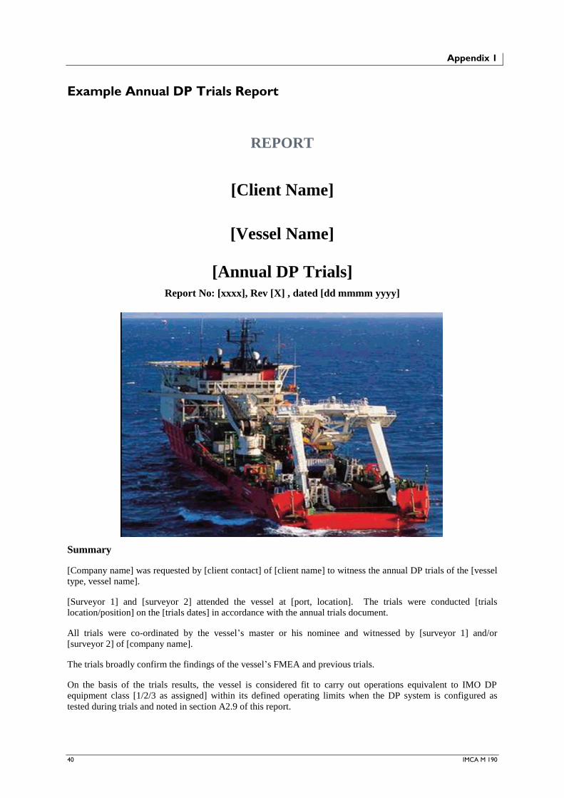
40 IMCA M 190
Appendix 1
Example Annual DP Trials Report
REPORT
[Client Name]
[Vessel Name]
[Annual DP Trials]
Report No: [xxxx], Rev [X] , dated [dd mmmm yyyy]
Summary
[Company name] was requested by [client contact] of [client name] to witness the annual DP trials of the [vessel
type, vessel name].
[Surveyor 1] and [surveyor 2] attended the vessel at [port, location]. The trials were conducted [trials
location/position] on the [trials dates] in accordance with the annual trials document.
All trials were co-ordinated by the vessel‟s master or his nominee and witnessed by [surveyor 1] and/or
[surveyor 2] of [company name].
The trials broadly confirm the findings of the vessel‟s FMEA and previous trials.
On the basis of the trials results, the vessel is considered fit to carry out operations equivalent to IMO DP
equipment class [1/2/3 as assigned] within its defined operating limits when the DP system is configured as
tested during trials and noted in section A2.9 of this report.
IMCA M 190 41
Contents
A-1: Introduction .......................................................................................................... 42
A-1.1: Instruction ............................................................................................................................................................ 42
A-1.2: Scope of Work .................................................................................................................................................... 42
A-1.3: Key Personnel in Attendance at the Trials ................................................................................................... 42
A-1.4: Order of Trials..................................................................................................................................................... 42
A-1.5: Requirements During Testing ......................................................................................................................... 43
A-2: Vessel Particulars ................................................................................................. 44
A-2.1: General .................................................................................................................................................................. 44
A-2.2: Power Generation ............................................................................................................................................... 44
A-2.3: Thrusters ............................................................................................................................................................... 44
A-2.4: Vessel Management System ............................................................................................................................ 44
A-2.5: DP Control System ............................................................................................................................................ 44
A-2.6: DP Reference Sensors ....................................................................................................................................... 44
A-2.7: FME(C)A ............................................................................................................................................................. 44
A-2.8: Upgrades to [Vessel Name] Since Previous Trials .................................................................................... 45
A-2.9: Machinery Configuration for Trials ............................................................................................................... 45
A-3: Conclusions ........................................................................................................... 46
A-3.1: Trials Conclusions ............................................................................................................................................. 46
A-3.2: Documentation .................................................................................................................................................... 46
A-3.3: Machinery Maintenance ................................................................................................................................... 46
A-3.4: DP System Maintenance................................................................................................................................... 46
A-3.5: Incidents ............................................................................................................................................................... 46
A-3.6: Power Generation ............................................................................................................................................... 46
A-3.7: Power Distribution ............................................................................................................................................. 46
A-3.8: Power Management ........................................................................................................................................... 46
A-3.9: Control Loops ..................................................................................................................................................... 47
A-3.10: Environmental and Heading Sensors .......................................................................................................... 47
A-3.11: Position References ......................................................................................................................................... 47
A-3.12: DP Control ......................................................................................................................................................... 47
A-3.13: Personnel ............................................................................................................................................................ 47
A-4: Findings ................................................................................................................ 48
Appendix A – Status Report .......................................................................................... 51
Appendix B – DP Trials Checklist ................................................................................. 54

42 IMCA M 190
A-1: Introduction
A-1.1: Instruction
[Company name] was requested to witness the annual DP trials of the [vessel name]. Instructions were received
under purchase order number [xxxxxxxxxx] from [client contact of client name].
A-1.2: Scope of Work
The annual trials programme has been developed from the FMEA of the vessel‟s DP system and all related
equipment. The trials are intended to show that the vessel meets the requirements of IMCA M 103 – Guidelines
for the design and operation of dynamically positioned vessels, the IMO Guidelines for vessels with dynamic
positioning systems 1994 (MSC 645) and [relevant classification society name and rules reference, e.g. Lloyd‟s
Register Rules and Regulations for the Classification of Ships, Part 7 Chapter 4 – Dynamic Positioning
Systems].
IMO MSC/Circ. 645 states that “The annual survey should ensure that the DP system has been maintained in
accordance with the applicable parts of the guidelines and is in good working order. Further, an annual test of all
important systems and components should be carried out to document the ability of the DP vessel to keep
position after single failures associated with the assigned equipment class.”
A-1.3: Key Personnel in Attendance at the Trials
Master
Chief Officer/SDPO
1st Officer/SDPO
Chief Engineer
ETO
2nd Engineer
Vessel Superintendent (Trials co-ordinator)
Vendor Representative
Vendor Representative
Classification Society Surveyor
Witness
Witness
A-1.4: Order of Trials
[Surveyor 1] and [surveyor 2], representing [company name], witnessed the [20XX] annual trials, which are
shown in Appendix B, and noted relevant results, alarms and printouts of various tests and disconnections as
required.
Trials commenced at approximately [time and date] and were completed at approximately [time and date].
The trials were carried out at [trials location/position]. The water depth at the location was around [water depth].
The weather throughout the trial was [describe weather, wind etc.]. Seas were generally [describe sea state] and
there was a variable surface current of [describe surface current rate and direction].
During the trials, all important DP equipment was available [or describe equipment unavailable with reason].
IMCA M 190 43
A-1.5: Requirements During Testing
The client (vessel operator) will appoint a trials co-ordinator to schedule the necessary resources and organise
the conduct of the trials programme. This person must not be the [company name] surveyor.
During the trials, all relevant shipboard equipment is required to be fully operational. In particular, all
propulsion units and their controls, both manual and automatic, all power generation equipment, all computer
systems and all position reference systems must be fully functional, including their alarms, standby units, battery
backups, shutdowns, trips, etc.
All trials will be conducted with the approval of the master and with full regard to the safe navigation of the
vessel.
The trials co-coordinator (not the [company name] surveyor) will satisfy themselves by whatever means
necessary that a test can be conducted safely and any test that cannot be conducted safely will be cancelled.
A suitable and sufficient risk assessment should also be carried out by the vessel‟s staff for any tests where there
is a risk of equipment damage even if that test can be conducted safely. An unsatisfactory outcome will be
assumed for any test cancelled on the grounds of safety or equipment damage until proven otherwise.
Unless otherwise stated all tests will be carried out on full DP in realistic environmental conditions or with some
varying load on the system induced by movements of the vessel.
During the trials, the vessel‟s staff will assist as required in recording alarms and failures locally. Locally means
not only at the DP console but also at the ECR, the thruster room, etc.
Following failure tests, the system must not be reinstated until the DP operators, ECR staff and witnesses are
satisfied they understand the full effects of the failure and that all the information or indicators that show what
has occurred have been noted.
When reinstating systems after failure simulations, it must be ensured that all equipment has been configured
correctly, breakers reset, power supplies re-established and cables re-connected. Only when everyone is satisfied
that the system has been reset and has stabilised will the trials continue.
If there are any doubts about a test, it will be repeated. If test results are unexpected, then the test will also be
repeated. It should be noted that seemingly small or spurious faults in DP control systems may be the first
manifestations of a more serious problem.
Tests will proceed only when all those involved have been informed and (where necessary) suitable
communications have been set up, e.g. DP console to thruster room.
The tests will not only prove hardware redundancy and DP capability after failures but also that the operators
have the necessary training and experience to use the system and deal successfully with such failures.

44 IMCA M 190
A-2: Vessel Particulars
A-2.1: General
The [vessel name] is a [vessel type] built by [shipyard and delivery date if available]. The vessel is registered in
[port of registry] and is classed by [classification society].
Principal dimensions are:
LOA [XX.XXm];
Breadth [XX.XXm];
Depth [XX.XXm];
GRT [XXXX].
The vessel has a [describe main features such as diving spread, ROVs, cranes, helideck etc.].
A-2.2: Power Generation
[Brief description.]
A-2.3: Thrusters
The thruster and propulsion units consist of:
[bow thrusters];
[stern thrusters];
[main propulsion].
A-2.4: Vessel Management System
[Brief description.]
A-2.5: DP Control System
[Brief description.]
A-2.6: DP Reference Sensors
The reference systems consist of:
[DGPS];
[hydroacoustic];
[taut wire];
[gyro compasses];
[wind sensors];
[VRS].
A-2.7: FME(C)A
Details of latest FMEA or FMECA study. Date of latest revision, update or verification. Are all hardware/
software changes or upgrades included?

IMCA M 190 45
A-2.8: Upgrades to [Vessel Name] Since Previous Trials
Since the most recent trials carried out in [previous trials date], [describe hardware and software
upgrades/changes].
A-2.9: Machinery Configuration for Trials
[Description of configuration of generators, thrusters, switchboards, bus ties, auxiliaries etc. The configuration
should reflect normal operating condition which should in turn reflect any restrictions or recommendations
mentioned in the FMEA. Especially important with regard to open/closed bus tie.]

46 IMCA M 190
A-3: Conclusions
A-3.1: Trials Conclusions
The annual trials for the DP system were carried out on the [vessel name] on the [date]. The vessel was
subjected to a full set of tests in accordance with the vessel‟s annual trials checklist.
The trials mainly demonstrated the vessel‟s compliance with current DP rules and guidelines, i.e.:
[Relevant class rules, e.g. Lloyd‟s Rules and Regulations for the Classification of Ships, Part 7 Chapter 4 –
Dynamic Positioning Systems];
IMCA M 103 Rev. 1 – Guidelines for the design and operation of dynamically positioned vessels;
IMO Guidelines for vessels with dynamic positioning systems 1994.
On the basis of the trials results, the vessel is considered fit to carry out operations equivalent to IMO DP
equipment class 1/2/3 (as assigned) within its defined operating limits when the DP system is configured as
tested during trials and noted in section A-2.9 of this report.
OR
On the basis of the trials results, the vessel will be considered fit to carry out operations equivalent to IMO DP
equipment class 1/2/3 (as assigned) within its defined operating limits when the DP system is configured as
tested during the trials and noted in section A-2.9 of this report once the category A finding(s) described in
section A-4.2 of this report are satisfactorily closed out.
A-3.2: Documentation
The presented annual trials checklist normally begins with a review of documentation related to the maintenance
history of the vessel. This provides evidence that all DP related systems are adequately maintained. It also
demonstrates that the vessel is maintained by competent staff, backed up by shore-based management
experienced in the operation of DP vessels.
A-3.3: Machinery Maintenance
[General comments on maintenance and any outstanding tasks.]
A-3.4: DP System Maintenance
[General comments on maintenance and any outstanding tasks.]
A-3.5: Incidents
[Description of any reported incidents and close out actions.]
A-3.6: Power Generation
[e.g. The tests successfully demonstrated power generation, load sharing and shedding to be fully effective.
Each generator was demonstrated as being able to deliver full power.]
A-3.7: Power Distribution
[e.g. The tests successfully demonstrated the power distribution system redundancy.]
A-3.8: Power Management
[e.g. Tests were carried out to ensure that every generator could take full load. Load limitation to prevent
blackout is provided by the DP control system and also by the main switchboard. Both systems were tested
successfully. Auto start of standby generators on rising demand was successfully demonstrated.]
IMCA M 190 47
A-3.9: Control Loops
[e.g. Control loops for the thrusters (command and feedback) were tested between the DP system and the thruster
control cabinets and between the thruster control cabinets and the thrusters and found to fail safely, in
accordance with the vessel‟s FMEA and appropriate guidelines for DP vessels.]
A-3.10: Environmental and Heading Sensors
[e.g. All sensors were tested under normal and failed conditions and found to be satisfactory.]
A-3.11: Position References
[e.g. Both DGPS systems, the taut wire and the hydroacoustic system were tested successfully for accuracy in
the operational mode and for responses in failed conditions.]
A-3.12: DP Control
[e.g. The results of the tests on the DP control system were satisfactory. The independent joystick was also
tested and demonstrated to be operational following failure of both DP control computers.]
A-3.13: Personnel
[e.g. The vessel crew who carried out the tests were very capable and showed a very good understanding of the
systems. They were willing and keen to conduct the trials and to take advantage of the learning opportunities
that the trials provided.]

48 IMCA M 190
A-4: Findings
A-4.1: Findings from Trials
Findings are grouped under three headings:
A – For immediate attention;
B – For action when reasonably convenient;
C – For future attention/consideration.
Findings from previous annual trials which have not been closed out at the conclusion of these trials are to be
included with the original date of the finding.
A-4.2: A – Findings
There are no findings in this category.
OR
There are [x] findings in this category:
[finding];
[finding].
A-4.3: B – Findings
There are no findings in this category.
OR
There are [x] findings in this category:
[finding];
[finding].
A-4.4: C – Findings
There are no findings in this category.
OR
There are [x] findings in this category:
[finding];
[finding].
A-4.5: Items Open from Previous Annual Trial
The following items were considered to be open following review of previous annual DP trials report and
associated close out documentation:

IMCA M 190 49
Ref Finding Category
Closed Out During
These Trials?
Not Closed Out –
Add to This
Year’s Findings
A-4.6: Items Arising from these Trials which should be Considered for Updating the FMEA

50 IMCA M 190
Company‟s Conditions of Business dated dd mmmm yyyy.
[Company Name]
Signed:
[Name]
[Principal Surveyor]
Countersigned:
[Name]
[Job Title]
Dated: [Location], [dd mmmm yyyy]

IMCA M 190 51
Appendix A – Status Report
App-A1: Thrusters
Bow Tunnel
Thruster T4
Bow Azimuth
Thruster T3
Stern Azimuth
T2 (Stbd)
Stern Azimuth
Thruster T1
(Port)
Maintenance Records Checked:
Outstanding Maintenance:
Last Oil Analysis (Date):
Last Oil Analysis Result:
Thruster Running Hours:
Remarks:
App-A2: Engines
Main Diesel
Generator 1
Main Diesel
Generator 2
Main Diesel
Generator 3
Main Diesel
Generator 4
Maintenance Records Checked:
Outstanding Maintenance:
Last Oil Analysis (Date):
Last Oil Analysis Result:
Running Hours at Present:
Last Major Overhaul:
Remarks:
App-A3: Switchboard
Last Maintenance/Health Check
Contractors Name:
Date: Report no:
Any modifications since last trials?
Remarks:

52 IMCA M 190
App-A4: DP Sensors
Sensor Records Checked Remarks (Include Software Revision If Appropriate)
Gyros
MRU
Wind Sensors
Acoustic System
Taut Wire
DGPS
Remarks:
App-A5: DP and other Vessel Control Systems
Maintenance checked:
Last software revision (detail which system):
Remarks:
App-A6: Hardware Modifications
Have there been any modifications to DP system components since
last annual trials? Y/N/NA
Have modifications been tested? Y/N/NA
Have trials procedures been updated? Y/N/NA
App-A7: Capability and Footprint Plots
Are the correct capability plots onboard? Plots should include the
intact state and post worst case failure state as a minimum.
Reference IMCA M 103
Y/N
Are there verifying footprints onboard? Y/N
App-A8: Incidents
Have any incidents been recorded? Incidents may be recorded using
the IMCA reporting format or the company‟s own reporting process. Y/N
If yes – number of incidents?
Is there a documented satisfactory explanation? Give brief details as
appropriate

IMCA M 190 53
App-A9: Key DP Personnel
„Training‟ should include DPO certificates, relevant courses attended such as DP system maintenance, high
voltage training, integrated control system training, etc. Experience should include total DP operations
experience and time on the subject vessel.
Name Position Training Experience
Master
Senior DPO
Senior DPO
Junior DPO
Chief engineer
2nd engineer
3rd engineer
ETO
App-A10: FMEA and Trials
Remarks
FMEA – Last Revision and Date:
Have all findings been closed out? Yes/No
Any findings arising from the FMEA which are not
documented as being closed out should be entered in
the remarks column
Last Annual DP Trials – Date:
Have all findings been closed out? Yes/No
Have any open findings been included in the relevant
section of this report?
Yes/No
App-A11: Other Documentation
Remarks
Is there a vessel specific DP operations manual as
described in IMCA M 103 section 1.5?
Are there appropriate checklists covering field arrival
trials, location checklists, periodic checks as
appropriate for bridge and engine room?
Is a DP logbook kept up to date?
Do the key DP personnel have access to appropriate
IMCA guidance documents either via internet or hard
copy?
Are records available for vendors‟ visits for repair or
service of DP system components?

54 IMCA M 190
Appendix B – DP Trials Checklist
EQUIPMENT SUB-SYSTEM: POWER DISTRIBUTION
Test No 1: Failure of Port Side 480V Main Switchboard
FMEA
Reference:
Section 6.4.3 – Failure Effects of the 480V Distribution
Objective: To demonstrate that only the expected consumers are lost on failure of the port side 480V main
switchboard and that position is maintained on surviving generators and thrusters.
Method: Vessel on auto DP. All 4 generators and all 4 thrusters on line. 480V bus tie open. Emergency
switchboard supplied from starboard main switchboard.
1. Remove generators from the port side switchboard – leading to „black out‟ of port 480V
switchboard. Observe failures.
2.
Results Expected:
1. Black out of port side main 480V switchboard:
Loss of port aft azimuth thruster T1
Loss of forward azimuth thruster T3
Loss of 480V auxiliary switchboards 1P and 3P
Loss of 230V switchboard 1L
UPS DPA on battery
HPR UPS on battery
24V systems 1B and 2B on battery
Vessel maintains position with thrusters T2 and T4 supplied by starboard switchboard.
2.
Results:
1. As expected. No alarm to indicate that 24V system 1B was running on battery.
2.
Comments:
There was no indication to warn that the main power supply to 24V system 1B was failed. Alarm for 24V
system 2B mains failure as expected on VMS. Suspected faulty alarm channel to VMS.
Witnessed by: [Surveyor Name/s] Date: [dd/mm/yy]

IMCA M 190 55
EQUIPMENT SUB-SYSTEM: POWER GENERATION AND AUXILIARY SERVICES
Test No 2: Load Reduction
FMEA
Reference:
Section 8.4.2 – DP Control System – Load Reduction
Objective: To confirm that the DP control system will reduce load effectively to prevent blackout.
Method: Vessel on DP joystick control. 2 generators on line (one on each switchboard) and all 4
thrusters on line. 480V bus tie open. Emergency switchboard supplied from starboard main
switchboard.
1. With offline generators NOT selected as standby. Increase power demand using joystick.
2. Return joystick to neutral to reduce demand.
3. Select offline generators as standby.
4. Increase power demand using joystick.
Results Expected:
1. When power consumption reaches 80% of available power on either bus, DP system will give
warning “Power limit reached on Bus X”. When power consumption reaches 85% of available
power, alarm will be given “Demand Reduced on Bus X”. Thrust will be limited regardless of
joystick demand to keep power consumption at 85%.
2. Demand reduces. Alarms cleared.
3. 2 generators on line. 2 on standby.
4. When power consumption reaches 80% of available power on either bus, DP system will give
warning “Power Limit Reached on Bus X”. Standby generators will start, run up and
synchronise to main switchboards. When power consumption reaches 85% of available power,
alarm will be given “Demand Reduced on Bus X”. Thrust will be limited regardless of joystick
demand to keep power consumption at 85%. As standby generator synchronises and connects
to main switchboard, DP system will allow power consumption to rise to meet joystick
demand.
Results:
1. As expected. See note regarding power limit settings.
2. As expected.
3. As expected.
4. As expected. See note regarding power limit settings.
Comments:
It was noted during testing and confirmed by DP control system field engineer that the limit for “Power limit
reached” is set at 85% and limit for “Demand Reduced” is set at 90%. The FMEA should be revised to reflect
the true settings and this test procedure also revised.
Witnessed by: [Surveyor Name/s] Date: [dd/mm/yy]

56 IMCA M 190
EQUIPMENT SUB-SYSTEM: DP CONTROL SYSTEM
Test No 3: DP Controllers
FMEA
Reference:
Section 8.3.1 – Failure Effects of the DP Controllers
Objective: To confirm that the DP control system will effect a „bumpless‟ transfer to the standby
controller in the event of failure of the master unit. Also to demonstrate that non availability of
the offline controller is alarmed to warn the DP operator that the redundancy concept has been
compromised.
Method: Vessel on auto DP. All 4 thrusters on line. Sufficient generators on line. 480V bus tie open.
Emergency switchboard supplied from starboard main switchboard.
1. With controller A as master and controller B as standby. Fail controller B.
2. With controller A as master and controller B as standby. Fail controller A.
3. With controller B as master and controller A as standby. Fail controller A.
4. With controller B as master and controller A as standby. Fail controller B.
Results Expected:
1. Alarm to indicate controller B failed. No effect on positioning. Controller A remains as
master.
2. Bumpless changeover to controller B. No effect on positioning. Alarms to indicate failure of
Controller A.
3. Alarm to indicate controller A failed. No effect on positioning. Controller B remains as master.
4. Bumpless changeover to controller A. No effect on positioning. Alarms to indicate failure of
Controller B.
Results:
1. As expected.
2. As expected.
3. As expected.
4. As expected.
Comments:
Witnessed by: [Surveyor Name/s] Date: [dd/mm/yy]

IMCA M 190 57
Appendix 2
Example Trials Summary Letter
CLIENT NAME
VESSEL NAME – Annual DP Trial 20XX
COMPANY NAME was instructed to witness the annual DP trials of the VESSEL TYPE/VESSEL NAME at the
request of CLIENT REPRESENTATIVE.
SURVEYOR NAME 1 and SURVEYOR NAME 2 of COMPANY NAME attended the vessel at PORT OF
JOINING. The trials were conducted at TRIALS LOCATION from X-Y MONTH 20XX in accordance with
TITLE, NUMBER AND REVISION LEVEL OF ANNUAL DP TRIALS DOCUMENT.
All trials were co-ordinated by NAME OF CLIENT TRIALS CO-ORDINATOR/S or their nominees and
witnessed by DP SURVEYOR 1 and DP SURVEYOR 2 of COMPANY NAME.
The trials broadly confirm the findings of the vessel‟s FMEA and previous trials.
On the basis of the trials results, the VESSEL NAME is considered fit to carry out DP operations equivalent to
IMO DP Equipment class 1/2/3 (delete as appropriate), within the defined operating limits and system
configurations of the vessel. USE THIS PARAGRAPH IF THERE ARE NO CATEGORY A FINDINGS.
OR
On the basis of the trials results, the “VESSEL NAME” is considered fit to carry out DP operations equivalent
to IMO DP Equipment Class 1/2/3 (delete as appropriate), within the defined operating limits of the vessel,
when those findings arising from the trials, which require „immediate attention‟, have been addressed. USE
THIS PARAGRAPH IF THERE ARE CATEGORY A FINDINGS AND ADD LIST BELOW.
For Immediate Attention:
[1] Test No. A „Test Title‟: – Vessel lost all electrical power when 110Vdc supply to starboard 600V
switchboard was failed.
[2] Test No. B „Test Title‟: – Azimuth thruster T3 immediately failed to full speed when the thruster speed
command signal was failed.
Full report and analysis of the trials to follow.
COMPANY NAME
For COMPANY NAME

58 IMCA M 190
Appendix 3
Example Findings List
CLIENT NAME
VESSEL NAME – Annual DP Trials 20XX – Provisional Findings
The annual DP trials of the VESSEL NAME were carried out at TRIALS LOCATION from X-Y MONTH 20XX
in accordance with TITLE, NUMBER AND REVISION LEVEL OF ANNUAL DP TRIALS DOCUMENT.
The following list of provisional findings was generated from the trials results and graded into three categories
in line with IMCA guidelines.
A full report and analysis of the trials results will follow.
Category A – For Immediate Attention:
[1] Test No. A „Test Title‟: – Vessel lost all electrical power when the 110Vdc supply to the starboard 600V
main switchboard was failed.
OR There are no findings in this category.
Category B – For Attention when Reasonably Convenient:
[1] Test No. B „Test Title‟: – It was not possible to test the taut wire due to the trials being carried out in
very deep water. This system will be tested in accordance with annual trials method prior to
operational use.
[2] Test No. C „Test Title‟: – Generator 5 failed during trials and is now unavailable. Provided that the
other generators are available, generator 5 provides non-critical redundancy.
OR There are no findings in this category.
Category C – For Consideration:
[1] Test No. D „Test Title‟: – The vessel is not provided with a DP alert system (red/yellow/green). IMCA
guidelines recommend such a system for ROV operations.
OR There are no findings in this category.
COMPANY NAME
For COMPANY NAME