guardshield type 4 and guardshield remote teach · 2017-10-13 · throughout this manual we use...
TRANSCRIPT
GuardShield Type 4 and GuardShield Remote Teach User Manual

Important User Information
Because of the variety of uses for the products described in this publication, those responsible for theapplication and use of this control equipment must satisfy themselves that all necessary steps have beentaken to assure that each application and use meets all performance and safety requirements, includingany applicable laws, regulations, codes and standards.
Reproduction of the contents of this copyrighted publication, in whole or part, without written permissionof Rockwell Automation, is prohibited.
Throughout this manual we use notes to make you aware of safety considerations:
The illustrations, charts, sample programs and layout examples shown in the guide are intended solely forpurposes of example. Since there are many variables and requirements associated with any particularinstallation, Rockwell Automation does not assume responsibility or liability (to include intellectual propertyliability) for actual use based upon the examples shown in this publication.
Rockwell Automation publication SGI-1.1, Safety Guidelines for the Application, Installation andMaintenance of Solid-State Control (available from your local Rockwell Automation sales office), describessome important differences between solid-state equipment and electromechanical devices that should betaken into consideration when applying products such as those described in this publication.
It is recommended that you save this user manual for future use.
Identifies information about practices or circumstances that can cause an explosion in a hazardous environment, which may lead to personal injury or death, property damage, or economic loss.
Identifies information that is critical for successful application and understanding of the product.
Identifies information about practices or circumstances that can lead to personal injury or death, property damage, or economic loss. Attentions help you identify a hazard, avoid a hazard, and recognize the consequences.
SHOCK HAZARD Labels may be on or inside the equipment (for example, drive or motor) to alert people that dangerous voltage may be present.
BURN HAZARD Labels may be on or inside the equipment (for example, drive or motor) to alert people that surfaces may reach dangerous temperatures.
WARNING
IMPORTANT
ATTENTION
GuardShield™ Safety Light Curtain User Manual
1R
Original instructions
Conditions required for proper use of theGuardShield Safety Light Curtain
Please make sure you read and understand these requirements before you select and install the GuardShield safety light curtain. GuardShield safety light curtains are point of operation safeguarding devices. These safety light curtains are intended to be used to provide point of operation safeguarding of personnel on a variety of machinery.
GuardShield safety light curtains are presence sensing devices and will not protect personnel from heat, chemicals, or flying parts. They are intended to signal a stop of hazardous machine motion when the sensing field is broken.
The GuardShield family of safety light curtains are general purpose presence sensing devices which are designed to protect personnel working on or near machinery.
It is the responsibility of the employer to properly install, operate and maintain the product as well as the machinery on which the GuardShield presence sensing device is installed.
The installation of GuardShield safety light curtains must comply with all applicable federal, state, and local rules, regulations, and codes.
GuardShield safety light curtains must be properly installed by qualified personnel.
GuardShield safety light curtains can only be used on machinery which can be stopped anywhere in its stroke or cycle.
GuardShield safety light curtains should never be used on full revolution clutched machinery.
The effectiveness of the GuardShield safety light curtains depends upon the integrity of the machinecontrol circuit. The machinery on which the GuardShield presence sensing device is installed shouldhave control circuitry that is fail safe in design.
All stopping mechanisms for the machinery should be inspected regularly to ensure proper operation.The protected machinery must have a consistent reliable and repeatable stopping time.
ATTENTION Failure to read and follow these instructions can lead to misapplication or misuseof the GuardShield safety light curtains, resulting in personal injury and damageto equipment.
GuardShield™ Safety Light Curtain User Manual
2 R
Original instructions
Table of Contents
GuardShield Safety Light Curtain . . . . . . . . . . . 3
Introduction . . . . . . . . . . . . . . . . . . . . . . . . . . . . . . . . . . . .3
Safety Precautions. . . . . . . . . . . . . . . . . . . . . . . . . . . . . . . .3Principles of Safe Use and Symbols Used . . . . . . . . . . . . . . . . . . . 3
Specialist Personnel . . . . . . . . . . . . . . . . . . . . . . . . . . . . . .4Range of Uses of the Device. . . . . . . . . . . . . . . . . . . . . . . . . . . . . . 4
Proper Use . . . . . . . . . . . . . . . . . . . . . . . . . . . . . . . . . . . . . . . . . . . . 4
General Protective Notes and Protective Measures. . . . . . . . . . . . 4
Product Description . . . . . . . . . . . . . . . . . . . . . . . . . . . . . .4Special Features . . . . . . . . . . . . . . . . . . . . . . . . . . . . . . . . . . . . . . . . 4
Light Curtain Principle of Operation . . . . . . . . . . . . . . . . . . . . . . . 5
Examples of Range of Use . . . . . . . . . . . . . . . . . . . . . . . . . . . . . . . 6
Safety Functions . . . . . . . . . . . . . . . . . . . . . . . . . . . . . . . . . . . . . . . 6
Blanking . . . . . . . . . . . . . . . . . . . . . . . . . . . . . . . . . . . . . . . . . . . . . . 7
Installation and Mounting . . . . . . . . . . . . . . . . . . . . . . . . 11Correct Installation . . . . . . . . . . . . . . . . . . . . . . . . . . . . . . . . . . . . 12
Incorrect Installation . . . . . . . . . . . . . . . . . . . . . . . . . . . . . . . . . . . 12
Response Time. . . . . . . . . . . . . . . . . . . . . . . . . . . . . . . . . . . . . . . . . 9
Determining the Safety Distance . . . . . . . . . . . . . . . . . . . .9US Safety Distance Formula . . . . . . . . . . . . . . . . . . . . . . . . . . . . . . 9
OSHA Safety Distance Calculation Formula . . . . . . . . . . . . . . . . 10
The ANSI Safety Distance Formula . . . . . . . . . . . . . . . . . . . . . . . 10
European Safety Distance Formula . . . . . . . . . . . . . . . . . . . . . . . 10
Multiple GuardShields . . . . . . . . . . . . . . . . . . . . . . . . . . . . . . . . . . 14
Mounting Brackets. . . . . . . . . . . . . . . . . . . . . . . . . . . . . . . . . . . . . 14
Electrical Installation . . . . . . . . . . . . . . . . . . . . . . . . . . . . 15Connections . . . . . . . . . . . . . . . . . . . . . . . . . . . . . . . . . . . . . . . . . . 15
Wiring Diagram . . . . . . . . . . . . . . . . . . . . . . . . . . . . . . . . . . . . . . . 17
Checklist . . . . . . . . . . . . . . . . . . . . . . . . . . . . . . . . . . . . . . . . . . . . . 21
System Status Indicators . . . . . . . . . . . . . . . . . . . . . . . . . . . . . . . . 20
System Configuration . . . . . . . . . . . . . . . . . . . . . . . . . . . . 18Teach Function . . . . . . . . . . . . . . . . . . . . . . . . . . . . . . . . . . . . . . . 19
Troubleshooting Guide . . . . . . . . . . . . . . . . . . . . . . . . . . . . . . . . . 19
This manual covers the operation and installation of the:
• Standard and cascading GuardShield light curtain
• Remote Teach GuardShield
• GuardShield with Integrated Laser Alignment
• GuardShield with Integrated Laser Alignment and ArmorBlock
Guard I/O
Safety Instructions—Maintenance . . . . . . . . . . . . . . . . . 21Daily Inspection . . . . . . . . . . . . . . . . . . . . . . . . . . . . . . . . . . . . . . 21
Six-month Inspection . . . . . . . . . . . . . . . . . . . . . . . . . . . . . . . . . . 22
Cleaning . . . . . . . . . . . . . . . . . . . . . . . . . . . . . . . . . . . . . . . . . . . . . 22
Technical Specifications . . . . . . . . . . . . . . . . . . . . . . . . . . . . . . . . 23
Model Overview . . . . . . . . . . . . . . . . . . . . . . . . . . . . . . . . . . . . . . 24
Dimensions . . . . . . . . . . . . . . . . . . . . . . . . . . . . . . . . . . . . . . . . . . 28
GuardShield Remote Teach . . . . . . . . . . . . . . . 30
Introduction . . . . . . . . . . . . . . . . . . . . . . . . . . . . . . . . . . . . . . . . . 30
System Delivery . . . . . . . . . . . . . . . . . . . . . . . . . . . . . . . . 30Remote Teach Box--Keyswitch Positions . . . . . . . . . . . . . . . . . . 30
System Installation . . . . . . . . . . . . . . . . . . . . . . . . . . . . . . . . . . . . 30
Remote Teach Procedure . . . . . . . . . . . . . . . . . . . . . . . . . . . . . . . 31
Remote Teach System Catalog Numbers. . . . . . . . . . . . . . . . . . . 31
Accessories. . . . . . . . . . . . . . . . . . . . . . . . . . . . . . . . . . . . 33
Rockwell Automation reserves the right to make changes or revisions
to the material contained in this publication and cannot be held liable
for incidental or consequential damages resulting from the furnishing,
performance or use of this material.
IMPORTANTSave these instructions for use at a future time.
Generally recognized technical regulations and quality assurance system ISO 9000 are carefully applied during the development and production of Allen-Bradley/Guardmaster products.
This technical description must be followed when installing and commissioning the GuardShield. Inspection and commissioning must be carried out by a qualified person.
R
GuardShield™ Safety Light Curtain User Manual
3Original instructions
GuardShield Safety Light Curtain
IntroductionThe GuardShield family of safety light curtains are general purpose
presence sensing devices, designed for use on hazardous machinery
providing point of operation, as well as, perimeter and access
detection.
It is a self-contained, two box, Type 4 ESPE (Electro Sensitive
Protective Equipment) with DIP-switch selectable operating modes.
The GuardShield is offered in a number of configurations based on a
standard Type 4 safety light curtain platform.
In addition to the standard GuardShield, the GuardShield is offered
with a Remote Teach box used to externally teach fixed blanking, in a
cascading configuration which allows the interconnection of up to
three pair of Guard Shields, with an integrated laser alignment system
in standard and cascadable configurations and with connectivity to
ArmorBlock Guard I/O for network connectivity providing OSSDs
over a DeviceNet safety network. The ArmorBlock Guard I/O option
is available in standard and cascadable versions with the integrated
laser system.
Features of the GuardShield, which are integrated into the system’s
receiver;
• Fixed blanking
• Floating blanking
• External device monitoring (EDM)
• Internal or external restart
• Beam coding
• Laser alignment (option)
Safety Precautions
Principles for Safe Use and Symbols UsedThe following instructions are preventive warnings to ensure the safe
and proper operation of the GuardShield. These instructions are an
essential part of the safety precautions and therefore have to be
observed at any time.
Throughout this manual we use the labels ATTENTION and
IMPORTANT to alert you to the following:
Failure to observe may result in dangerous operation
ATTENTION: Identifies information about
practices of circumstances that can lead to personal injury or death,
property damage, or economic loss.
ATTENTION helps you
• Identify a hazard
• Avoid a hazard
• Recognize the consequences
IMPORTANT: Identifies information that is especially important for
successful application and understanding of the product.
IMPORTANTThese installation instructions are designed to address the technical personnel of the machine manufacturer and or the installer of the safety system regarding the proper mounting, configuration, electrical installation, commissioning, operation and maintenance of the GuardShield safety light curtain. These installation instructions do not provide instruction for the operation of machinery to which the GuardShield safety light curtain is, or will be, integrated. Only qualified personnel should install this equipment.
ATTENTION
ATTENTIONPotentially hazardous situation, which, if not prevented, might lead to serious or deadly injury.Failure to observe may result in dangerous operation.
ATTENTIONThe GuardShield must not be used with machines that cannot be stopped electrically in an emergency.The safety distance between the GuardShield and a dangerous machine movement has to be
maintained at all times.Additional mechanical protective devices have to be installed in a way that hazardous machine elements cannot be reached without passing through the protective field.The GuardShield has to be installed in a way that operators can only operate within the sensing area. Improper installation can result in serious injury.Never connect the outputs to +24V DC. If the outputs are connected to +24V DC, they are in ON-state and cannot stop hazardous spots at the machine/application.Never expose the GuardShield to flammable or explosive gases.Regular safety inspections are imperative (see maintenance).Do not repair or modify the GuardShield. The GuardShield safety light curtain is not field repairable and can only be repaired at the factory. Removal of either of the GuardShield endcaps will void the warranty terms of this product.

GuardShield™ Safety Light Curtain User Manual
4 R
Original instructions
Specialist PersonnelThe GuardShield safety light curtain must be installed, commissioned
and serviced only by a qualified person. A qualified person is defined
as a person who:
• Has undergone the appropriate technical training
and
• Who has been instructed by the responsible machine operator in
the operation of the machine and the currently valid safety
guidelines
and
• Who has read and has ongoing access to these installation
instructions
Range of Uses of the DeviceThe GuardShield safety light curtain is classified as electro-sensitive
protective equipment (ESPE). The physical resolution is 14 mm (0.55
in.) or 30 mm (1.18 in.). The maximum protective field width is 7 m
(22.9 ft) for the 14 mm (0.55 in.) resolution and 18 m (59 ft) for the 30
mm (1.18 in.) resolution GuardShield. The protective field height is
between 160 mm (6.3 in.) and 1760 mm (69.2 in.).
The GuardShield with an Integrated Laser Alignment system is
offered in protected heights from 320 to 1600 mm in increments of
160 mm. All GuardShield light curtains with ArmorBlock Guard I/O
have Integrated Laser Alignment.
The device is a Type 4 ESPE as defined by IEC 61496-1 and CLC/TS
61496-2 and is therefore allowed for use with controls in safety
category Type 4 in compliance with EN ISO 13849, SIL CL3 in
accordance with EN62061 or up to PLe in accordance with EN ISO
13849. The device is suitable for:
• Point of operation protection (finger and hand protection)
• Hazardous area protection
• Access protection
Access to the hazardous point must be allowed only through the
protective field. The machine/system is not allowed to start as long as
personnel are within the hazardous area. Refer to the “Examples of
Range of Use” on page 6 for an illustration of the protection modes.
Depending on the application, mechanical protection devices may be
required in addition to the safety light curtain.
Proper UseThe GuardShield safety light curtain must be used only as defined in
the “Range of Uses of the Device.” It must be used only by qualified
personnel and only on the machine where it has been installed and
initialized by qualified personnel.
If the device is used for any other purposes or modified in any way,
warranty claims against Allen-Bradley/Guardmaster shall become null
and void.
General Protective Notes and Protective Measures
• The national/international rules and regulations apply to the
installation, use and periodic technical inspections of the safety
light curtain, in particular:
♦ Machine Directive 2006/42/EC
♦ Low Voltage Directive 2006/95/EC
♦ Equipment Usage Directive 89/655/EEC
♦ The work safety regulations/safety rules
♦ Other relevant health and safety regulations
Manufacturers and users of the machine with which the safety
light curtain is used are responsible for obtaining and observing
all applicable safety regulations and rules.
• The notices, in particular the test regulations of these installation
instructions (e.g. on use, mounting, installation or integration
into the existing machine controller) must be observed.
• The tests must be carried out by specialist personnel or specially
qualified and authorized personnel and must be recorded and
documented to ensure that the tests can be reconstructed and
retraced at any time.
• The installation instructions must be made available to the user
of the machine where the GuardShield safety light curtain is
installed. The machine operator is to be instructed in the use of
the device by specialist personnel and must be instructed to read
the installation instructions.
Product DescriptionThis section provides information on the special features and
properties of the safety light curtain. It describes the structure and
functions of the unit, in particular the different operating modes.
� Please read this section before mounting, installing and commissioning the unit.
Special Features• Start interlock
• Restart interlock
• Teachable fixed blanking
• One or two beam floating blanking
• External Device Monitoring (EDM)
• Machine test signal
• Beam coding
IMPORTANTSafety NotesPlease observe the following items in order to ensure the proper and safe use of the GuardShield safety light curtain.

R
GuardShield™ Safety Light Curtain User Manual
5Original instructions
GuardShield Light Curtain Principle of OperationThe GuardShield safety light curtain consists of a non-matched pair of
optic units, i.e., transmitter and receiver with the same protected height
and resolution. The transmitter and receiver operate on +24V DC.
The maximum distance between transmitter and receiver is referred to
as the protective field width or range. The protective field height is the
distance between the first and last beam in the device.
The transmitter emits sequential pulses of infrared light which are
received and processed by the GuardShield receiver. The
synchronization of the timing of the emission and reception of
infrared light pulses is accomplished optically by the first beam
adjacent to the GuardShield status LEDs. This beam is referred to as
the synchronization beam. Because the GuardShield transmitter and
receiver are optically synchronized, no electrical connection is required
between the transmitter and receiver.
The GuardShield receiver has two safety outputs, Output Signal
Switching Devices (OSSDs) and one nonsafety auxiliary output. When
the GuardShield transmitter and receiver are properly powered and
aligned, all OSSDs are current sourcing +24V DC with a switching
capacity of 500 mA. The two safety OSSDs are cross monitored and
short-circuit protected. Interruption of the sensing field causes the
receiver to switch the sourced current OFF (0V DC).
Restoring the GuardShield sensing field, (in Guard only configuration)
causes all outputs (OSSDs) to switch to the active high state (resume
current sourcing +24V DC with a switching capacity of 500 mA).
The GuardShield Light CurtainThe GuardShield safety light curtain consists of a transmitter and a
receiver.
Figure 1: Components of the GuardShield
The upper and lower limit of the protective field is shown by markings
on the housings.
The GuardShield with an Integrated Laser Alignment system has the
limits of the protected height indicated by the yellow border on the
laser label and target label.
The width of the protective field is derived from the length of the
light path between sender and receiver and must not exceed the
maximum rated width of the protective field (7 m…14 mm (22.9
ft…0.55 in.), 18 m…30 mm (59.0 ft…1.18 in.)).
CascadingThe GuardShield, Type 4 POC is also available in cascading segments
which allow a number of GuardShield transmitters and receivers to be
interconnected. This product configurability allows the GuardShield to
protect multiple sides of a machine or simply adds flexibility when
positioning the GuardShield in various applications.
Standard GuardShield cascading segments are offered in protective
heights from 320 to 1760 mm in both 14 mm and 30 mm resolutions.
Cascading segments of 160 mm are not offered, however a 160 mm
GuardShield can be used as the last segment in a cascading system.
Cascading GuardShields with an integrated laser alignment system are
offered in protected heights from 320 mm to 1600 mm. It is possible
to mix standard GuardShield light curtains with integrated laser
alignment systems.
A maximum of three GuardShield light curtains can be interconnected
with a common pair of OSSDs. There are no limitations for the total
number of beams in a cascading system and the maximum number of
beams possible is in three 1760 mm, 14 mm resolution GuardShield
interconnected segments. The individual segments can have mixed
resolutions, i.e., 14 mm and 30 mm as long as the pairs have the same
protective heights and resolutions.
Cascading segments can be used as standalone light curtain pairs or
can have up to three segments interconnected. These cascading
segments all function as independent light curtains.
When cascading segments are used as standalone pairs or as the last
segment in a cascading system, it is necessary to use a termination plug
on the top connector of the GuardShield cascading receiver. It is also
Transmitter Receiver
Up to three GuardShield POC segments can be interconnected.

GuardShield™ Safety Light Curtain User Manual
6 R
Original instructions
possible to use a standard GuardShield Type 4 POC pair as the last
segment in a cascading system.
Examples of Range of UseThe GuardShield safety light curtain operates as a proper protective
device only if the following conditions are met:
• The control of the machine must be electrical.
• The controlled machine must be able to be stopped any where
in the machines stroke or cycle.
• The transmitter and receiver must be mounted such that access
to the hazard is only through the light curtain’s protective field.
• The restart button must be located outside the hazardous area
such that it cannot be operated by a person working inside the
hazardous area.
• The statutory and local rules and regulations must be observed
when installing and using the device.
Restart interlock is not available in GuardShield light curtains with
ArmorBlock Guard I/O connectivity.
GuardShield Laser AlignmentThe laser light source in the Integrated Laser Alignment system of the
GuardShield light curtains is a Class 1, eye safe laser diode with a
wavelength of 670 nm.
This Class 1, eye safe laser is switched from a low output power state
to a high output power state (and back again) by means of control
circuitry which detects reflected laser light from a temporary blockage
of the emitted laser light. This is most commonly accomplished by a
person’s finger placed over the laser overlay window. There is also an
automatic shutdown feature that switches the laser diode from the
high power state to the low power state if there is no finger or other
interruption detected for a period of five minutes.
During the high output mode of operation, the laser is pulsed at a rate
of approximately 2 Hz in order to facilitate finger detection in high
ambient light conditions.
Safety FunctionsThe GuardShield safety light curtain offers a variety of functions,
which are integral to the system.
Operating modes, functions and features of the GuardShield system
are activated through DIP switch settings.
Guard OnlyWhen in the guard only mode of operation, the light curtain operates
as an on/off device, meaning the OSSD outputs switch off/on
according to an obstruction or clearing of the detection field. The
GuardShield is shipped from the factory configured in Guard only
mode.
Start Interlock The start interlock prevents the OSSD outputs from switching to ON
state after power up of the system with the protective field
unobstructed. A manual reset of the system is required for the
GuardShield to enter the ON state.
This can be accomplished by one of two methods.
• Actuation of a momentary N.O. push button
• Interruption and restoration of the protective field within one
second.
Activation of this mode of operation and selection of the resetting
method is through DIP-switch settings. Indication of this mode of
operation is through illumination of a yellow LED on the GuardShield
receiver.
Start interlock is not available on middle and end segments of a
cascading GuardShield system, however, it is possible to configure this
operating mode in the host segment allowing the whole cascading
system to operate in this mode. Start interlock is not available in
GuardShield light curtains with ArmorBlock Guard I/O connectivity.
Restart InterlockThe restart interlock mode of operation prevents the OSSD outputs
from switching to ON after interruption and clearance of the
protective field. A manual reset of the GuardShield system is required.
Resetting of the system is accomplished through a momentary N.O.
push button or key switch. Configuration and activation of this mode
of operation is through DIP-switch settings. The restart interlock
mode is indicated by the illumination of a yellow LED on the
GuardShield receiver.
Restart interlock is not available on middle and end segments of a
cascading GuardShield system, however, it is possible to configure this
operating mode in the host segment allowing the whole cascading
system to operate in this mode.
Restart interlock is not available in GuardShield light curtains with
ArmorBlock Guard I/O connectivity.
Relay Monitoring (MPCE/EDM)The relay monitoring function is an input signal to the GuardShield
receiver and is used to monitor the state of the protected machinery’s
primary control contactors or other final switching device. Detection
of unsafe conditions such as welded contacts, cause the GuardShield
to enter a lockout condition (OSSDs OFF). Activation of this mode of
operation is through DIP-switch setting in the GuardShield receiver.
IMPORTANTAdditional measures may be necessary to ensure that the ESPE does not fail to danger when other forms of light radiation are present in a particular application (i.e., use of cableless control devices on cranes, radiation from weld spatter or effects from strobe lights).
ATTENTIONUse of controls or adjustments or performance of procedures other than those specified herein, may result in hazardous radiation exposure.
IMPORTANTThe protective system must be tested for proper operation after each and every change to the configuration.

R
GuardShield™ Safety Light Curtain User Manual
7Original instructions
EDM is not available in the middle and end segments of a cascading
GuardShield system, however, it is possible to configure this operating
mode in the host segment allowing the whole cascading system to
operate in this mode.
External Device Monitoring (EDM) is not available in GuardShield
light curtains with ArmorBlock Guard I/O connectivity.
System TestingThe GuardShield performs a complete system self-test at power up
and switches to the ON state if the system is properly aligned and the
protective field is unobstructed and the start/restart interlock modes
of operation are deactivated.
External Test (Machine Test Signal)A test cycle of the system can be triggered by an external test signal to
the GuardShield transmitter. Supplying or removing a signal (+24V
DC) via a N.C. or N.O. switch at the test input deactivates the
transmitter for the duration of the test signal, simulating an
interruption of the protective sensing field. The test input must be
configured via a DIP-switch located in the GuardShield transmitter.
External test signal is not available in the middle and end segments of
a cascading GuardShield system, however, it is possible to configure
this feature in the host segment allowing the whole cascading system
to operate in this mode.
Beam CodingIf several safety light curtains are operating in close proximity to one
another, it is possible that the transmitter’s infrared light from one
GuardShield system is “seen” by another GuardShield system’s
receiver. This would cause a “nuisance” stop. To prevent this optical
interference, the GuardShield has the ability to have the transmitter
generate different beam patterns, which is referred to as “Beam
coding.” Selection and activation of beam coding is accomplished
through DIP-switch settings in both the transmitter and receiver.
The following settings are available in the GuardShield safety light
curtain; noncoded and coded.
BlankingThe GuardShield safety light curtain is capable of fixed blanking of
one or more adjacent beams, exclusive of the synchronization beam.
Floating blanking of one or two beams is also capable of being
configured. It is possible to activate both fixed and floating blanking
simultaneously.
Each cascading GuardShield segment pair functions as a standalone
safety light curtain with its OSSDs connected in series to the host
segment’s OSSDs, therefore, it is necessary to configure fixed and/or
floating blanking in each individual pair segment. This is accomplished
by first aligning all segment pairs and securing the brackets. It is then
possible to open a segment pair’s receiver door using the security tool
provided, set the appropriate DIP switches and perform the teach
function. The successful completion of the teach function changes the
operating mode of that segment pair only.
Fixed BlankingThe fixed blanking mode of operation is activated through DIP-switch
settings located in the GuardShield receiver. The beams to be blanked
are “taught” by depressing the teach button located in the GuardShield
receiver endcap while the object is in the GuardShield sensing field.
The fixed blanking mode of operation is monitored. If any part or all
of the object is removed from the sensing field, the GuardShield
OSSD outputs go to the OFF state.
The GuardShield fixed blanking mode of operation will not be
activated until the teach function is complete and the access door is
closed.
Note: “Hard guards” refer to mechanical barriers.
IMPORTANTIf a test cycle of a cascading system is required, it is necessary to have all transmitters in a cascading system configured in the same condition, i.e. all “active high” or all “active low.”
Beam coding improves resistance to optical interference.Beam coding increases the system’s response time, which may also increase the required safety distance. Refer to Safety Distance calculations on page 9 of this manual.
IMPORTANT
IMPORTANTBalanced areas may require an additional risk analysis. If no mechanical or other guarding is used to restrict access to the hazard, the blanked area must be taken into consideration in the calculation of the safety distance.
The configuration and activation of fixed blanking creates a “hole” in the GuardShield protective field. If the fixed object that is located in the protective field does not completely fill the area between the GuardShield transmitter and receiver it is necessary to obstruct access to the hazard by additional means. This is usually accomplished by “hard guarding” the open area.
IMPORTANT
GuardShield™ Safety Light Curtain User Manual
8 R
Original instructions
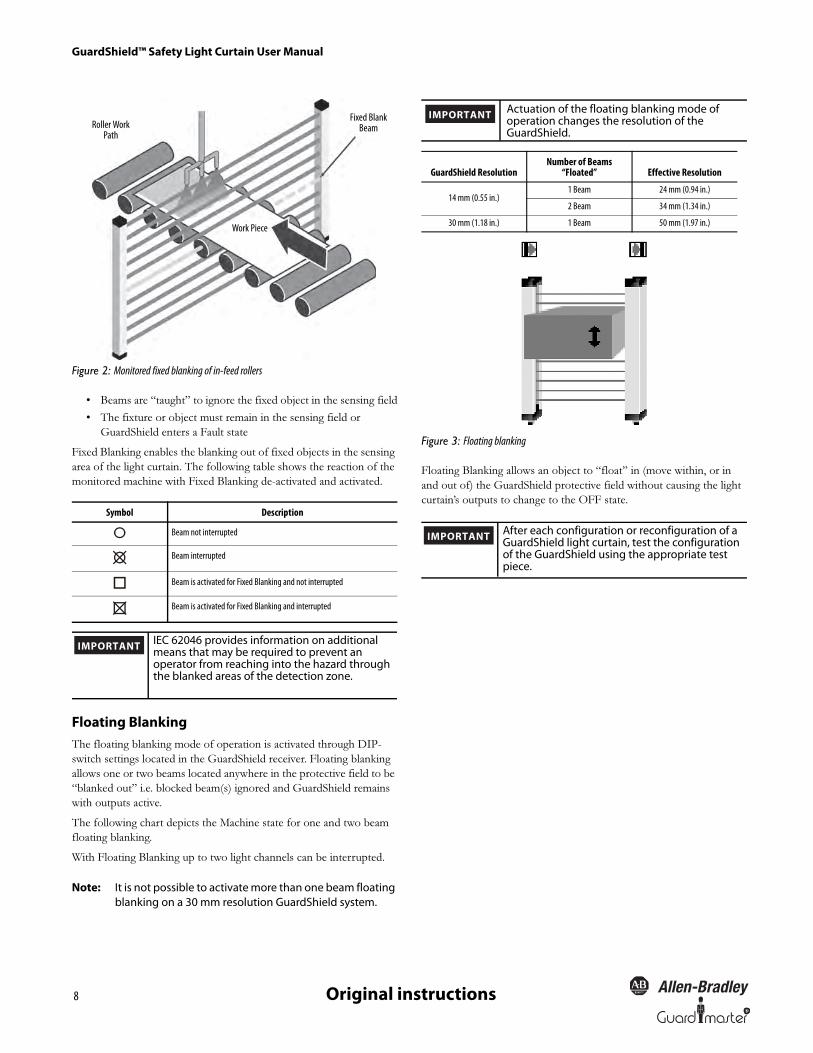
Figure 2: Monitored fixed blanking of in-feed rollers
• Beams are “taught” to ignore the fixed object in the sensing field
• The fixture or object must remain in the sensing field or
GuardShield enters a Fault state
Fixed Blanking enables the blanking out of fixed objects in the sensing
area of the light curtain. The following table shows the reaction of the
monitored machine with Fixed Blanking deactivated and activated.
Floating BlankingThe floating blanking mode of operation is activated through DIP-
switch settings located in the GuardShield receiver. Floating blanking
allows one or two beams located anywhere in the protective field to be
“blanked out” i.e. blocked beam(s) ignored and GuardShield remains
with outputs active.
The following chart depicts the Machine state for one and two beam
floating blanking.
With Floating Blanking up to two light channels can be interrupted.
Note: It is not possible to activate more than one beam floating blanking on a 30 mm resolution GuardShield system.
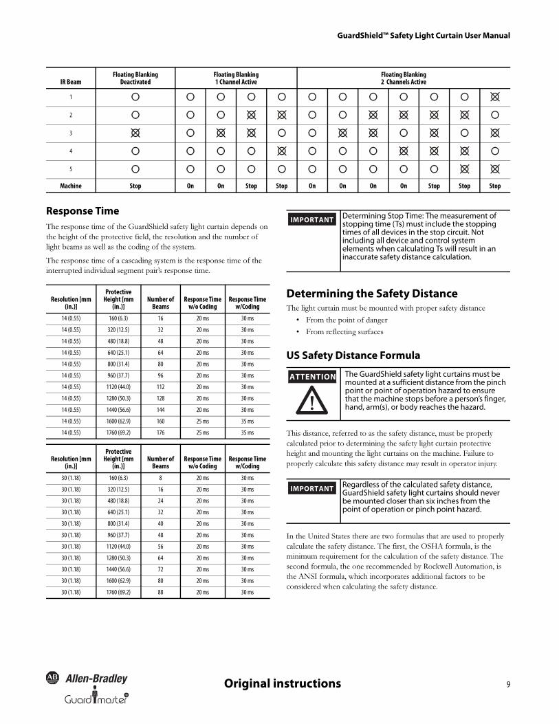
Figure 3: Floating blanking
Floating Blanking allows an object to “float” in (move within, or in
and out of) the GuardShield protective field without causing the light
curtain’s outputs to change to the OFF state.Symbol Description
Beam not interrupted
Beam interrupted
Beam is activated for Fixed Blanking and not interrupted
Beam is activated for Fixed Blanking and interrupted
Work Piece
Roller Work Path
Fixed Blank Beam
IMPORTANTIEC 62046 provides information on additional means that may be required to prevent an operator from reaching into the hazard through the blanked areas of the detection zone.
GuardShield ResolutionNumber of Beams
“Floated” Effective Resolution
14 mm (0.55 in.)1 Beam 24 mm (0.94 in.)
2 Beam 34 mm (1.34 in.)
30 mm (1.18 in.) 1 Beam 50 mm (1.97 in.)
IMPORTANTActuation of the floating blanking mode of operation changes the resolution of the GuardShield.
IMPORTANTAfter each configuration or reconfiguration of a GuardShield light curtain, test the configuration of the GuardShield using the appropriate test piece.
R
GuardShield™ Safety Light Curtain User Manual
9Original instructions
Response TimeThe response time of the GuardShield safety light curtain depends on
the height of the protective field, the resolution and the number of
light beams as well as the coding of the system.
The response time of a cascading system is the response time of the
interrupted individual segment pair’s response time.
Determining the Safety DistanceThe light curtain must be mounted with proper safety distance
• From the point of danger
• From reflecting surfaces
US Safety Distance Formula
This distance, referred to as the safety distance, must be properly
calculated prior to determining the safety light curtain protective
height and mounting the light curtains on the machine. Failure to
properly calculate this safety distance may result in operator injury.
In the United States there are two formulas that are used to properly
calculate the safety distance. The first, the OSHA formula, is the
minimum requirement for the calculation of the safety distance. The
second formula, the one recommended by Rockwell Automation, is
the ANSI formula, which incorporates additional factors to be
considered when calculating the safety distance.
IR BeamFloating Blanking
DeactivatedFloating Blanking1 Channel Active
Floating Blanking2 Channels Active
1
2
3
4
5
Machine Stop On On Stop Stop On On On On Stop Stop Stop
Resolution [mm (in.)]
Protective Height [mm
(in.)]Number of
BeamsResponse Time
w/o CodingResponse Time
w/Coding
14 (0.55) 160 (6.3) 16 20 ms 30 ms
14 (0.55) 320 (12.5) 32 20 ms 30 ms
14 (0.55) 480 (18.8) 48 20 ms 30 ms
14 (0.55) 640 (25.1) 64 20 ms 30 ms
14 (0.55) 800 (31.4) 80 20 ms 30 ms
14 (0.55) 960 (37.7) 96 20 ms 30 ms
14 (0.55) 1120 (44.0) 112 20 ms 30 ms
14 (0.55) 1280 (50.3) 128 20 ms 30 ms
14 (0.55) 1440 (56.6) 144 20 ms 30 ms
14 (0.55) 1600 (62.9) 160 25 ms 35 ms
14 (0.55) 1760 (69.2) 176 25 ms 35 ms
Resolution [mm (in.)]
Protective Height [mm
(in.)]Number of
BeamsResponse Time
w/o CodingResponse Time
w/Coding
30 (1.18) 160 (6.3) 8 20 ms 30 ms
30 (1.18) 320 (12.5) 16 20 ms 30 ms
30 (1.18) 480 (18.8) 24 20 ms 30 ms
30 (1.18) 640 (25.1) 32 20 ms 30 ms
30 (1.18) 800 (31.4) 40 20 ms 30 ms
30 (1.18) 960 (37.7) 48 20 ms 30 ms
30 (1.18) 1120 (44.0) 56 20 ms 30 ms
30 (1.18) 1280 (50.3) 64 20 ms 30 ms
30 (1.18) 1440 (56.6) 72 20 ms 30 ms
30 (1.18) 1600 (62.9) 80 20 ms 30 ms
30 (1.18) 1760 (69.2) 88 20 ms 30 ms
Determining Stop Time: The measurement of stopping time (Ts) must include the stopping times of all devices in the stop circuit. Not including all device and control system elements when calculating Ts will result in an inaccurate safety distance calculation.
IMPORTANT
ATTENTION The GuardShield safety light curtains must be mounted at a sufficient distance from the pinch point or point of operation hazard to ensure that the machine stops before a person’s finger, hand, arm(s), or body reaches the hazard.
Regardless of the calculated safety distance, GuardShield safety light curtains should never be mounted closer than six inches from the point of operation or pinch point hazard.
IMPORTANT

GuardShield™ Safety Light Curtain User Manual
10 R
Original instructions
OSHA Safety Distance Calculation FormulaThe OSHA safety distance formula as specified in CFR Subpart O
1910.217 is as follows:
Ds = 63 X TS
Ds Safety Distance
63 Is the OSHA recommended hand speed constant in inches per second
Ts Is the total stop time of all devices in the safety circuit, measured in seconds. This value must include all components involved in stopping the hazardous motion of the machinery. For a mechanical power press it is the stopping time measured at approximately the 90º position of the crankshaft rotation.
Note: The TS number must include the response times of all devices, including the response time of the safety light curtain, the safety light curtain controller (if used), the machine’s control circuit and any other devices that react to stop the hazardous motion of the machinery. Not including the response time of a device or devices in the stop time calculation will result in insufficient safety distance for the application. This may result in operator injury.
The ANSI Safety Distance FormulaThe ANSI safety distance formula, which is the Rockwell Automation
recommended formula, is as follows:
DS = K x (T
S + T
C + Tr + Tbm) + Dpf
Ds Minimum safety distance between the safe guarding device and the nearest point of operation hazard, in inches.
K Hand speed constant in inches per second. The ANSI standard value is 63 inches per second when the operator begins reaching toward the point of operation hazard from rest. NOTE: ANSI B11.19 1990 E4.2.3.3.5 states “The value of the hand speed constant, K, has been determined by various studies and although these studies indicate speeds of 63 inches/second to over 100 inches/second, they are not conclusive determinations. The employer should consider all factors, including the physical ability of the operator, when determining the value of K to be used.”
Ts Stop time of the machine tool measured at the final control element.
Tc Response time of the control system
Note: Ts and Tc are usually measured by a stop time measuring device.
Tr Response time of the presence sensing device (safety light curtain) and its interface, if any. This value is generally stated by the device manufacturer or it can be measured by the user.
Tbm Additional time allowed for the brake monitor to compensate for variations in normal stopping time.
Dpf Depth penetration factor. It is an added distance to allow for how far into the protective field an object, such as a finger or hand, can travel before being detected. Dpf is
related to the safety light curtain’s object sensitivity. Object sensitivity is the smallest diameter object which will always be detected anywhere in the sensing field.
European Safety Distance FormulaA safety distance must be maintained between the light curtain and the
point of danger. This safety distance ensures that the point of danger
can only be reached after the dangerous state of the machine has been
completely removed.
The safety distance as defined in EN ISO 13855 and EN ISO 13857
depends on:
• Stopping/run-down time of the machine or system. (The
stopping/run-down time is shown in the machine
documentation or must be determined by taking a
measurement.)
• Response time of the protective device, e.g. GuardShield (for
“Response Time” see page 9).
• Reach or approach speed.
• Resolution of the light curtain and/or beam separation.
Figure 4: Safety distance from the point of danger
How to Calculate the Safety Distance S
According to EN ISO 13855 and EN ISO 13857:
� First, calculate S using the following formula:S = 2000 × T + 8 × (d – 14) [mm]
Where …
T = stopping/run-down time of the machine
+ response time of the protective device [s]
d = resolution of the light curtain [mm]
S = safety distance [mm]
The reach/approach speed is already included in the formula.
� If the result S is ≤ 500 mm (19.6 in.), then use the determined value as the safety distance.
Pointof
danger
Protective field height
Safety distance S (Ds)
Distance to avoid standing behind the safety curtain ≤75 mm

R
GuardShield™ Safety Light Curtain User Manual
11Original instructions
� If the result S is > 500 mm (19.6 in.), then recalculate S as follows:S = 1600 × T + 8 × (d – 14) [mm]
� If the new value S is > 500 mm (19.6 in.), then use the newly determined value as the minimum safety distance.
� If the new value S is ≤ 500 mm (19.6 in.), then use 500 mm (19.6 in.) as the safety distance.
Example:
Stopping/run-down time of the machine = 290 ms
Response time = 30 ms
Resolution of the light curtain = 14 mm (0.55 in.)
T = 290 ms + 30 ms = 320 ms = 0.32 s
S = 2000 × 0.32 + 8 × (14 – 14) = 640 mm (25.1 in.)
S > 500 mm, therefore:
S = 1600 × 0.32 + 8 × (14 – 14) = 512 mm (20.1 in.)
Example:
In opto-electronic safeguarding, such as with a perpendicular safety
light curtain applications with object sensitivity (effective resolution)
less than 2.5 inches, the Dpf can be approximated based on the
following formula:
Dpf (inches) =3.4 × (Object Sensitivity – 0.276),
but not less than 0.
Minimum Distance from Reflecting SurfacesThe infrared light from the sender may be reflected off of shiny
surfaces and be received by the system’s receiver. If this condition
occurs, it can result in an object not being detected when it enters the
GuardShield sensing field.
All reflecting surfaces and objects (e.g. material bins) must therefore be
located at a minimum distance a from the protective field of the
system. The minimum distance a depends on the distance D between
sender and receiver.
Figure 5: Minimum distance from reflecting surfaces
How to Determine the Minimum Distance from the
Reflecting Surfaces:
� Determine the distance D [m] sender-receiver
� Read the minimum distance a [mm] from the graph:
Figure 6: Graph, minimum distance from reflecting surfaces
The effective aperture angle for the GuardShield system is
+/- 2.5° at a mounting distance of > 3.0 m (9.8 ft). Calculate the
minimum distance to reflecting surfaces depending on the distance
between the transmitter and the receiver, using an aperture angle of +/
- 2.5°, or take the appropriate value from the following table:
Note: Formula: a = tan 2.5° x D [mm]
a = minimum distance to reflecting surfaces
D = distance between transmitter and receiver
Installation and MountingThis section describes the preparation, selection and installation of the
GuardShield safety light curtain.
The standard GuardShield has an amber LED in the receiver which is
used as an alignment aid. This LED will begin flashing when the
infrared light from the transmitter is “seen” by the receiver. This LED
turns off when optimal alignment is attained.
Alignment Procedure: Standard GuardShieldMount and connect both transmitter and receiver. They must be
parallel to each other and be positioned at the same height.
Turn on power to GuardShield system.
Rotate the transmitter while watching the amber LED on the receiver
to find the point where the indicator for the ON state (Green LED)
illuminates and the amber LED goes off.
Determine the maximum left and right turning angles and position
unit in center. Tighten all hardware assuring that the alignment
indicator is not illuminated.
a
Distance D (meters)
Distance Between Transmitter and Receiver (Range L) [m (ft)]
Minimum Distancea [mm (in.)]
0.2 to 3.0 (0.65 to 9.8) 135 (5.31)
4.0 (13.1) 175 (6.88)
5.0 (16.4) 220 (8.66)
6.0 (19.6) 265 (10.43)
7.0 (22.9) 310 (12.2)
10.0 (32.8) 440 (17.32)
16.0 (52.4) 700 (27.55)
GuardShield™ Safety Light Curtain User Manual
12 R
Original instructions
Cycle power to assure that the system powers up and goes to the ON
state (alignment indicator is OFF).
The GuardShield is also offered with an integrated laser alignment
system which has a constantly powered Class 1, eye safe laser located
in the top of the GuardShield transmitter and in the bottom of the
GuardShield receiver. Each laser emits a low level of visible light.
Simply blocking this light below the finger symbol causes the light to
be reflected back to a photo sensor which changes the condition of the
laser light. If this light is at a low level, interrupting it will cause the
laser to emit a highly visible level of light. Interrupting the visible light
in the same location will cause the laser to switch to a low level of
emission. The emission of visible light will also change to a low level
after five minutes of activation.
Across from each laser is a target used to help with the alignment of
the GuardShield pair. Positioning the visible light in the center of the
top and bottom targets will position the GuardShield pair for optimal
alignment.
An external laser (440L-ALAT) and mounting bracket (440LAF6109)
is offered as an accessory for aligning the GuardShield.
Alignment Procedure for GuardShield with Integrated Laser Alignment 1. Properly locate the GuardShield pair from the point of operation
hazard after performing the safety distance calculation.
2. Using the GuardShield mounting brackets, mount the transmitter
and receiver so that they are facing one another and are positioned
in the same direction. A reference would be that the indicator
LEDs are opposite one another.
3. Turn on each laser by placing a finger or hand in front of each laser.
4. For optimal alignment, adjust the transmitter and receiver in such a
way that both visible laser beams hit the laser targets opposite each
laser. A small deviation around the target is allowable.
The GuardShield safety light curtain is suitable for most operating
environments (IP65 environmental rating). Proper safety distance as
well as adequate protective height must be observed.
Determine if the machinery, on which the GuardShield is to be
mounted, meets the requirements as specified in the beginning of this
manual, i.e., machinery must be able to be stopped anywhere in its
stroke or cycle, consistently and repeatedly.
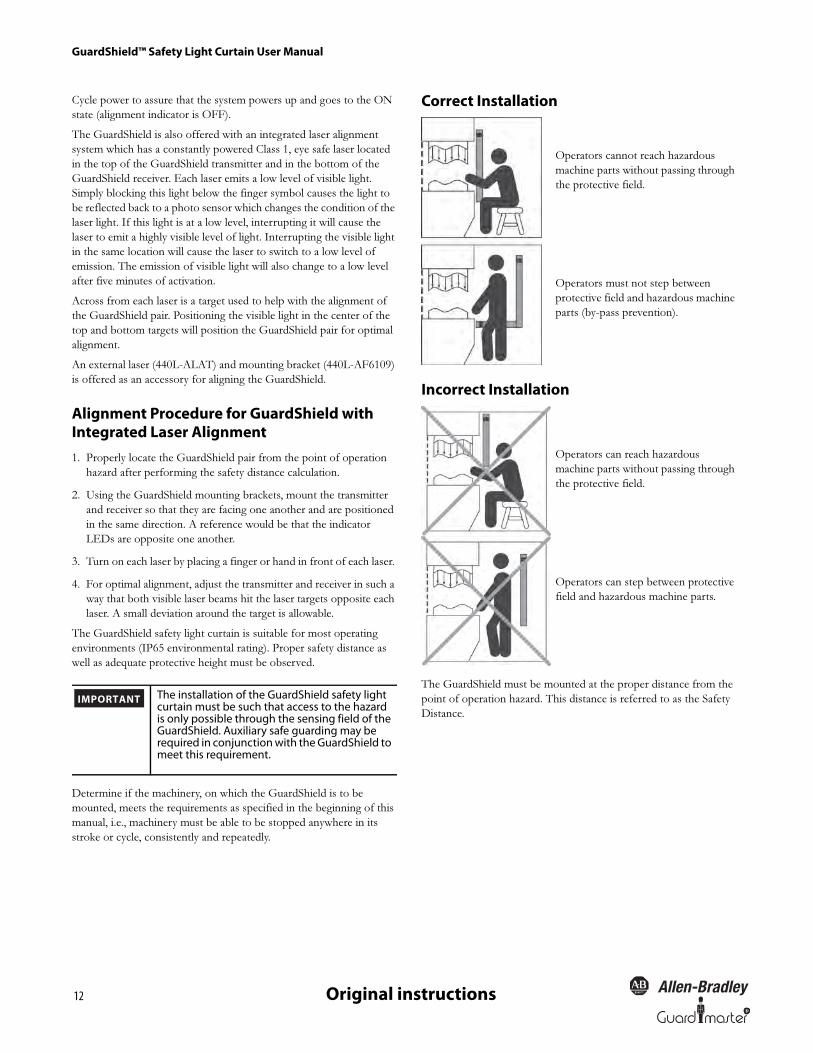
Correct Installation
Incorrect Installation
The GuardShield must be mounted at the proper distance from the
point of operation hazard. This distance is referred to as the Safety
Distance.
The installation of the GuardShield safety light curtain must be such that access to the hazard is only possible through the sensing field of the GuardShield. Auxiliary safe guarding may be required in conjunction with the GuardShield to meet this requirement.
IMPORTANT
Operators cannot reach hazardous
machine parts without passing through
the protective field.
Operators must not step between
protective field and hazardous machine
parts (by-pass prevention).
Operators can reach hazardous
machine parts without passing through
the protective field.
Operators can step between protective
field and hazardous machine parts.
R
GuardShield™ Safety Light Curtain User Manual
13Original instructions
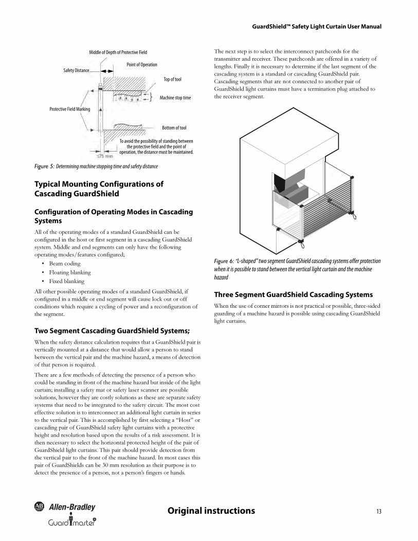
Figure 5: Determining machine stopping time and safety distance
Typical Mounting Configurations of Cascading GuardShield
Configuration of Operating Modes in Cascading SystemsAll of the operating modes of a standard GuardShield can be
configured in the host or first segment in a cascading GuardShield
system. Middle and end segments can only have the following
operating modes/features configured;
• Beam coding
• Floating blanking
• Fixed blanking
All other possible operating modes of a standard GuardShield, if
configured in a middle or end segment will cause lock out or off
conditions which require a cycling of power and a reconfiguration of
the segment.
Two Segment Cascading GuardShield Systems;When the safety distance calculation requires that a GuardShield pair is
vertically mounted at a distance that would allow a person to stand
between the vertical pair and the machine hazard, a means of detection
of that person is required.
There are a few methods of detecting the presence of a person who
could be standing in front of the machine hazard but inside of the light
curtain; installing a safety mat or safety laser scanner are possible
solutions, however they are costly solutions as these are separate safety
systems that need to be integrated to the safety circuit. The most cost
effective solution is to interconnect an additional light curtain in series
to the vertical pair. This is accomplished by first selecting a “Host” or
cascading pair of GuardShield safety light curtains with a protective
height and resolution based upon the results of a risk assessment. It is
then necessary to select the horizontal protected height of the pair of
GuardShield light curtains. This pair should provide detection from
the vertical pair to the front of the machine hazard. In most cases this
pair of GuardShields can be 30 mm resolution as their purpose is to
detect the presence of a person, not a person’s fingers or hands.
The next step is to select the interconnect patchcords for the
transmitter and receiver. These patchcords are offered in a variety of
lengths. Finally it is necessary to determine if the last segment of the
cascading system is a standard or cascading GuardShield pair.
Cascading segments that are not connected to another pair of
GuardShield light curtains must have a termination plug attached to
the receiver segment.
Figure 6: “L-shaped” two segment GuardShield cascading systems offer protection when it is possible to stand between the vertical light curtain and the machine hazard
Three Segment GuardShield Cascading SystemsWhen the use of corner mirrors is not practical or possible, three-sided
guarding of a machine hazard is possible using cascading GuardShield
light curtains.
Middle of Depth of Protective Field
Safety DistancePoint of Operation
Top of tool
Bottom of tool
To avoid the possibility of standing between the protective field and the point of
operation, the distance must be maintained.
Protective Field Marking
Machine stop time
GuardShield™ Safety Light Curtain User Manual
14 R
Original instructions
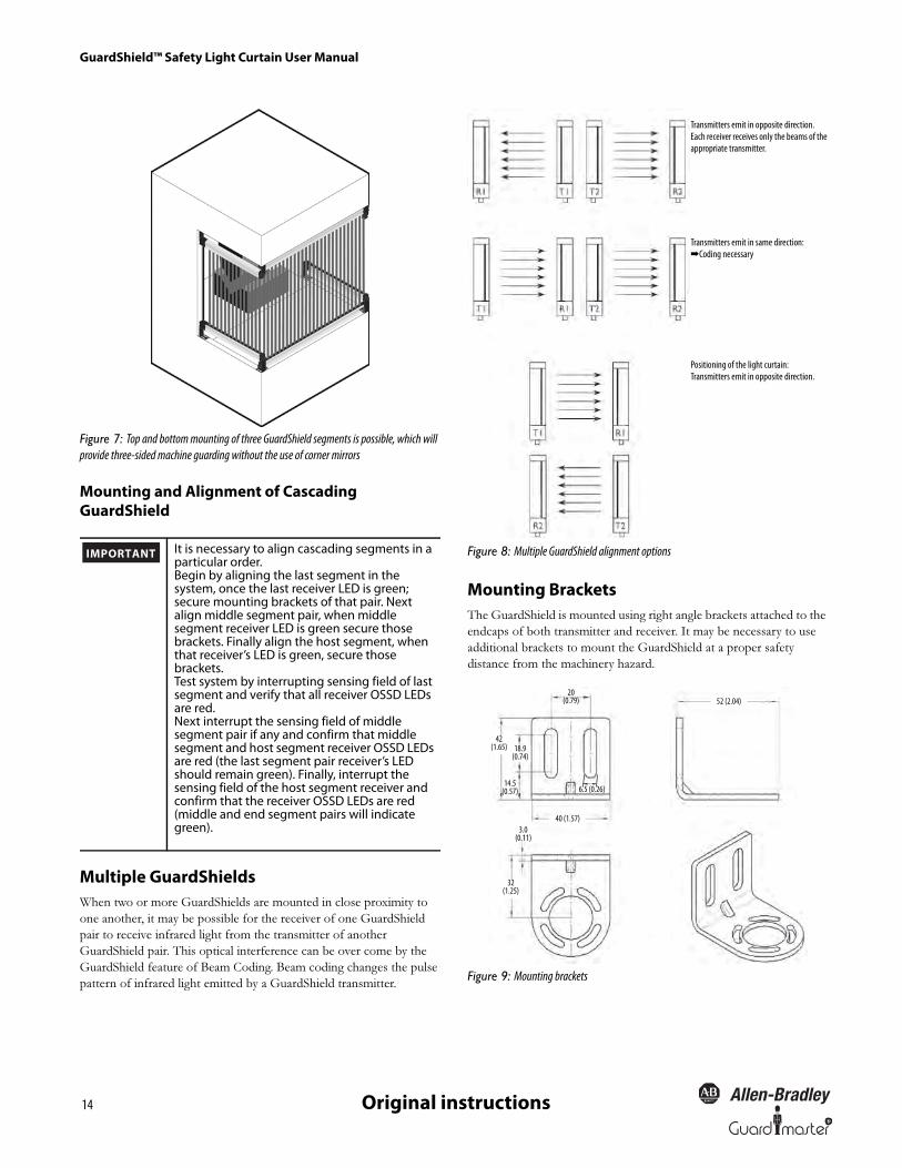
Figure 7: Top and bottom mounting of three GuardShield segments is possible, which will provide three-sided machine guarding without the use of corner mirrors
Mounting and Alignment of Cascading GuardShield
Multiple GuardShieldsWhen two or more GuardShields are mounted in close proximity to
one another, it may be possible for the receiver of one GuardShield
pair to receive infrared light from the transmitter of another
GuardShield pair. This optical interference can be over come by the
GuardShield feature of Beam Coding. Beam coding changes the pulse
pattern of infrared light emitted by a GuardShield transmitter.
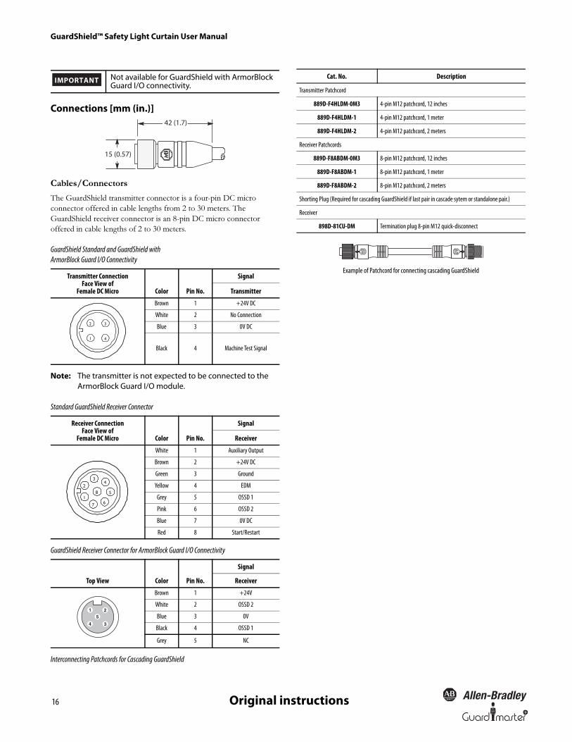
Figure 8: Multiple GuardShield alignment options
Mounting BracketsThe GuardShield is mounted using right angle brackets attached to the
endcaps of both transmitter and receiver. It may be necessary to use
additional brackets to mount the GuardShield at a proper safety
distance from the machinery hazard.
Figure 9: Mounting brackets
It is necessary to align cascading segments in a particular order.Begin by aligning the last segment in the system, once the last receiver LED is green; secure mounting brackets of that pair. Next align middle segment pair, when middle segment receiver LED is green secure those brackets. Finally align the host segment, when that receiver’s LED is green, secure those brackets.Test system by interrupting sensing field of last segment and verify that all receiver OSSD LEDs are red.Next interrupt the sensing field of middle segment pair if any and confirm that middle segment and host segment receiver OSSD LEDs are red (the last segment pair receiver’s LED should remain green). Finally, interrupt the sensing field of the host segment receiver and confirm that the receiver OSSD LEDs are red (middle and end segment pairs will indicate green).
IMPORTANT
Transmitters emit in opposite direction. Each receiver receives only the beams of the appropriate transmitter.
Transmitters emit in same direction:➡Coding necessary
Positioning of the light curtain: Transmitters emit in opposite direction.
Noncoded Coded
42 (1.65)
20 (0.79)
40 (1.57)
18.9(0.74)
14.5(0.57)
52 (2.04)
3.0(0.11)
32 (1.25)
6.5 (0.26)

R
GuardShield™ Safety Light Curtain User Manual
15Original instructions
Optional Middle Mounting Bracket (440L-AF6108)
Figure 10: Middle mounting brackets
Note: Middle mounting brackets should be used in vibration applications for protective heights of 1120 mm and larger.
GuardShield Remote Teach Receiver Bracket
Figure 11: Remote teach receiver bracket
Electrical Installation
Connections
Power SupplyThe external voltage supply (+24V DC) must meet the requirements
of IEC 61496-1. In addition, the following requirements have to be
fulfilled:
• A short-term power failure of 20 ms must be bridged by the
power supply.
• The power supply has double insulation between the primary
and the secondary side.
• The power supply is protected against overload.
• The power supply corresponds to the guidelines of the EWG
(industrial environment).
• The power supply corresponds to the Low Voltage Directives.
• The grounded conductor of the power supply device must be
connected to a grounded conductor PE.
• The maximum deviation of the voltage levels is 24V DC +/-
20%.
EDM Connection
Figure 12: Connecting the contact elements to the EDM
Figure 13: Connecting the reset button/restart button
49.2 (1.93)
40.2 (1.58)62
(2.44)
24 (0.94)
30 (1.18)20 (0.78)
Double insulationThis part of the insulation provides supplementary insulation against
hazardous voltage levels.
Motor, etc.
Hazardous voltage level
Basic insulation
Hazardous voltage level
Hazardous voltage level
Reinforced insulation or
double insulation
Unit 1
Power Supply Unit 2
Output (pink and grey)
Basic insulation(See note.) Basic insulation
0V (blue)
+24V (brown) K1 K1 K2 K2
GuardShield
24VPin 4 5
6
K1
K2
k2 k1Contactor Contacts
ContactorCoils
Not available for GuardShield with ArmorBlock Guard I/O connectivity.IMPORTANT
Reset/restart button
Pin 824V
GuardShield™ Safety Light Curtain User Manual
16 R
Original instructions
Connections [mm (in.)]
Cables/Connectors
The GuardShield transmitter connector is a four-pin DC micro
connector offered in cable lengths from 2 to 30 meters. The
GuardShield receiver connector is an 8-pin DC micro connector
offered in cable lengths of 2 to 30 meters.
GuardShield Standard and GuardShield with ArmorBlock Guard I/O Connectivity
Note: The transmitter is not expected to be connected to the ArmorBlock Guard I/O module.
Standard GuardShield Receiver Connector
GuardShield Receiver Connector for ArmorBlock Guard I/O Connectivity
Interconnecting Patchcords for Cascading GuardShield
Example of Patchcord for connecting cascading GuardShieldTransmitter Connection
Face View ofFemale DC Micro Color Pin No.
Signal
Transmitter
Brown 1 +24V DC
White 2 No Connection
Blue 3 0V DC
Black 4 Machine Test Signal
Receiver ConnectionFace View of
Female DC Micro Color Pin No.
Signal
Receiver
White 1 Auxiliary Output
Brown 2 +24V DC
Green 3 Ground
Yellow 4 EDM
Grey 5 OSSD 1
Pink 6 OSSD 2
Blue 7 0V DC
Red 8 Start/Restart
Top View Color Pin No.
Signal
Receiver
Brown 1 +24V
White 2 OSSD 2
Blue 3 0V
Black 4 OSSD 1
Grey 5 NC
Not available for GuardShield with ArmorBlock Guard I/O connectivity.
IMPORTANT
42 (1.7)
15 (0.57)
1 4
32
2
158
7 6
43
Cat. No. Description
Transmitter Patchcord
889D-F4HLDM-0M3 4-pin M12 patchcord, 12 inches
889D-F4HLDM-1 4-pin M12 patchcord, 1 meter
889D-F4HLDM-2 4-pin M12 patchcord, 2 meters
Receiver Patchcords
889D-F8ABDM-0M3 8-pin M12 patchcord, 12 inches
889D-F8ABDM-1 8-pin M12 patchcord, 1 meter
889D-F8ABDM-2 8-pin M12 patchcord, 2 meters
Shorting Plug (Required for cascading GuardShield if last pair in cascade sytem or standalone pair.)
Receiver
898D-81CU-DM Termination plug 8-pin M12 quick-disconnect
GuardShield™ Safety Light Curtain User Manual
17R
Original instructions
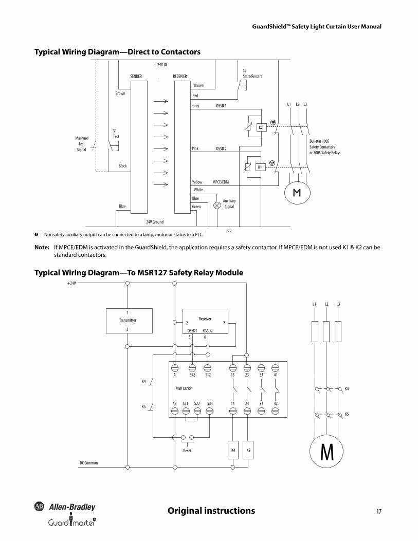
Typical Wiring Diagram—Direct to Contactors
� Nonsafety auxiliary output can be connected to a lamp, motor or status to a PLC.
Note: If MPCE/EDM is activated in the GuardShield, the application requires a safety contactor. If MPCE/EDM is not used K1 & K2 can be standard contactors.
Typical Wiring Diagram—To MSR127 Safety Relay Module
M
+ 24V DC
24V Ground
SENDER
OSSD 1
OSSD 2
RECEIVER
K1
Bulletin 100SSafety Contactorsor 700S Safety Relays
K2
L1 L3L2Gray
Pink
Green
Blue
Blue
Yellow
Brown
Brown
S2Start/Restart
Red
MPCE/EDM
S1Test
Black
MachineTest
Signal
White
AuxiliarySignal
+24V
3
1
A S12S52K4
Transmitter 72Receiver
L1
K5
OSSD2OSSD165
13 3323 41
A2 S22S21 14 3424 42S34
L2 L3
K4
K5
K4 K5
DC Common
Reset
MSR127RP
M
GuardShield™ Safety Light Curtain User Manual
18 R
Original instructions
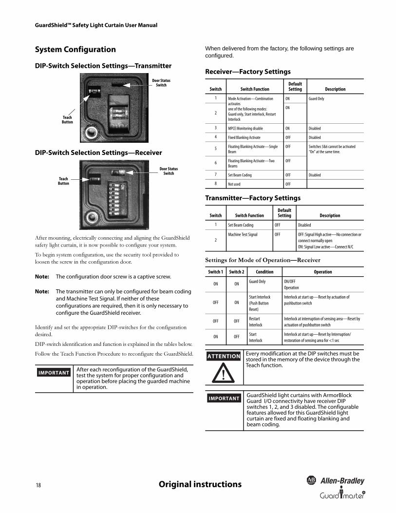
System Configuration
DIP-Switch Selection Settings—Transmitter
DIP-Switch Selection Settings—Receiver
After mounting, electrically connecting and aligning the GuardShield
safety light curtain, it is now possible to configure your system.
To begin system configuration, use the security tool provided to
loosen the screw in the configuration door.
Note: The configuration door screw is a captive screw.
Note: The transmitter can only be configured for beam coding and Machine Test Signal. If neither of these configurations are required, then it is only necessary to configure the GuardShield receiver.
Identify and set the appropriate DIP-switches for the configuration
desired.
DIP-switch identification and function is explained in the tables below.
Follow the Teach Function Procedure to reconfigure the GuardShield.
When delivered from the factory, the following settings are configured.
Receiver—Factory Settings
Transmitter—Factory Settings
Settings for Mode of Operation—Receiver
Door Status Switch
Teach Button
Door Status Switch
Teach Button
IMPORTANTAfter each reconfiguration of the GuardShield, test the system for proper configuration and operation before placing the guarded machine in operation.
Switch Switch FunctionDefault Setting Description
1 Mode Activation—Combination activates one of the following modes:Guard only, Start interlock, Restart Interlock
ON Guard Only
2ON
3 MPCE Monitoring disable ON Disabled
4 Fixed Blanking Activate OFF Disabled
5 Floating Blanking Activate—Single Beam
OFF Switches 5&6 cannot be activated “On” at the same time.
6 Floating Blanking Activate—Two Beams
OFF
7 Set Beam Coding OFF Disabled
8 Not used OFF
Switch Switch FunctionDefault Setting Description
1 Set Beam Coding OFF Disabled
2Machine Test Signal OFF OFF: Signal High active—No connection or
connect normally openON: Signal Low active—Connect N/C
Switch 1 Switch 2 Condition Operation
ON ON Guard Only ON/OFFOperation
OFF ONStart Interlock(Push ButtonReset)
Interlock at start up—Reset by actuation of pushbutton switch
OFF OFF Restart Interlock
Interlock at interruption of sensing area—Reset by actuation of pushbutton switch
ON OFF StartInterlock
Interlock at start up—Reset by Interruption/restoration of sensing area for <1 sec
ATTENTIONEvery modification at the DIP switches must be stored in the memory of the device through the Teach function.
IMPORTANTGuardShield light curtains with ArmorBlock Guard I/O connectivity have receiver DIP switches 1, 2, and 3 disabled. The configurable features allowed for this GuardShield light curtain are fixed and floating blanking and beam coding.
R
GuardShield™ Safety Light Curtain User Manual
19Original instructions
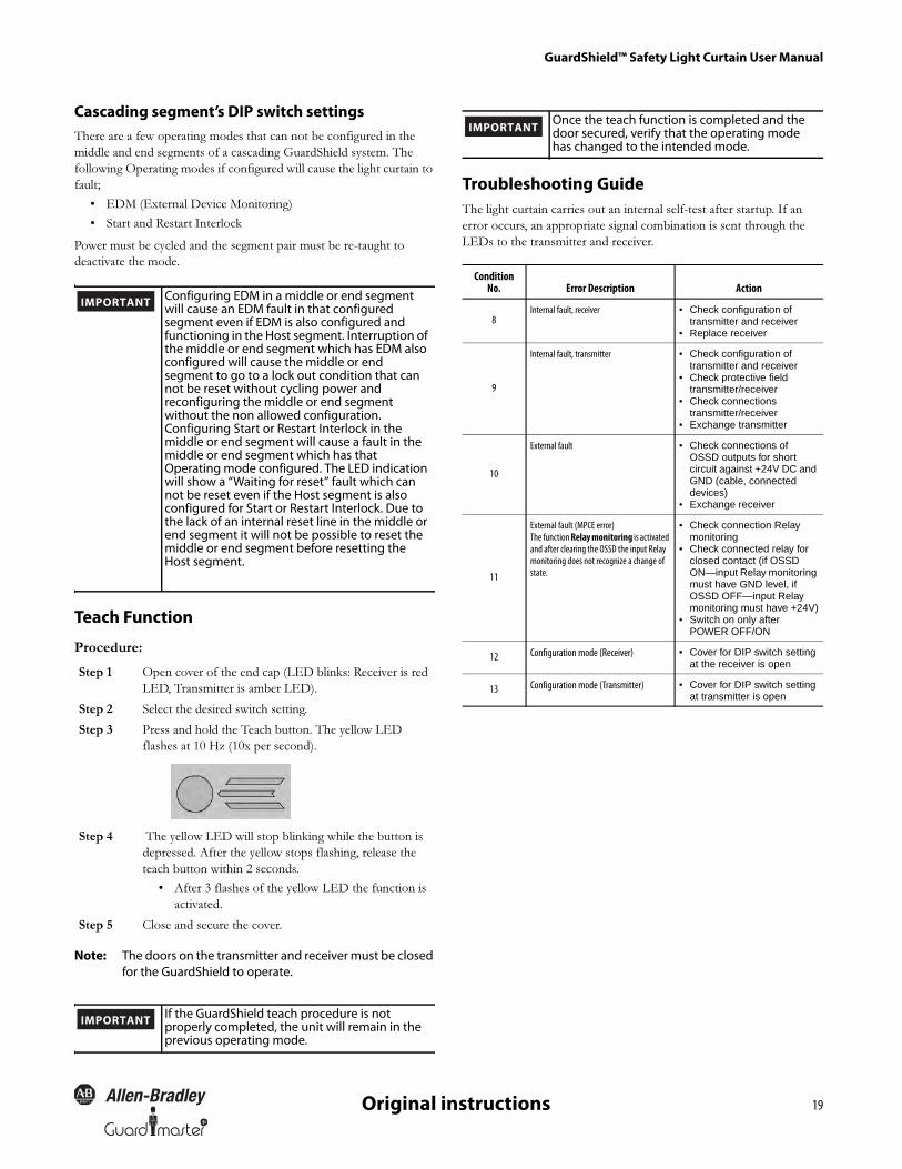
Cascading segment’s DIP switch settingsThere are a few operating modes that can not be configured in the
middle and end segments of a cascading GuardShield system. The
following Operating modes if configured will cause the light curtain to
fault;
• EDM (External Device Monitoring)
• Start and Restart Interlock
Power must be cycled and the segment pair must be re-taught to
deactivate the mode.
Teach Function
Procedure:
Note: The doors on the transmitter and receiver must be closed for the GuardShield to operate.
Troubleshooting GuideThe light curtain carries out an internal self-test after startup. If an
error occurs, an appropriate signal combination is sent through the
LEDs to the transmitter and receiver.
Step 1 Open cover of the end cap (LED blinks: Receiver is red
LED, Transmitter is amber LED).
Step 2 Select the desired switch setting.
Step 3 Press and hold the Teach button. The yellow LED
flashes at 10 Hz (10x per second).
Step 4 The yellow LED will stop blinking while the button is
depressed. After the yellow stops flashing, release the
teach button within 2 seconds.
• After 3 flashes of the yellow LED the function is
activated.
Step 5 Close and secure the cover.
Configuring EDM in a middle or end segment will cause an EDM fault in that configured segment even if EDM is also configured and functioning in the Host segment. Interruption of the middle or end segment which has EDM also configured will cause the middle or end segment to go to a lock out condition that can not be reset without cycling power and reconfiguring the middle or end segment without the non allowed configuration.Configuring Start or Restart Interlock in the middle or end segment will cause a fault in the middle or end segment which has that Operating mode configured. The LED indication will show a “Waiting for reset” fault which can not be reset even if the Host segment is also configured for Start or Restart Interlock. Due to the lack of an internal reset line in the middle or end segment it will not be possible to reset the middle or end segment before resetting the Host segment.
IMPORTANT
If the GuardShield teach procedure is not properly completed, the unit will remain in the previous operating mode.
IMPORTANT
ConditionNo. Error Description Action
8Internal fault, receiver • Check configuration of
transmitter and receiver• Replace receiver
9
Internal fault, transmitter • Check configuration of transmitter and receiver
• Check protective field transmitter/receiver
• Check connections transmitter/receiver
• Exchange transmitter
10
External fault • Check connections of OSSD outputs for short circuit against +24V DC and GND (cable, connected devices)
• Exchange receiver
11
External fault (MPCE error)The function Relay monitoring is activated and after clearing the OSSD the input Relay monitoring does not recognize a change of state.
• Check connection Relay monitoring
• Check connected relay for closed contact (if OSSD ON—input Relay monitoring must have GND level, if OSSD OFF—input Relay monitoring must have +24V)
• Switch on only after POWER OFF/ON
12 Configuration mode (Receiver) • Cover for DIP switch setting at the receiver is open
13 Configuration mode (Transmitter) • Cover for DIP switch setting at transmitter is open
Once the teach function is completed and the door secured, verify that the operating mode has changed to the intended mode.
IMPORTANT
GuardShield™ Safety Light Curtain User Manual
20 R
Original instructions
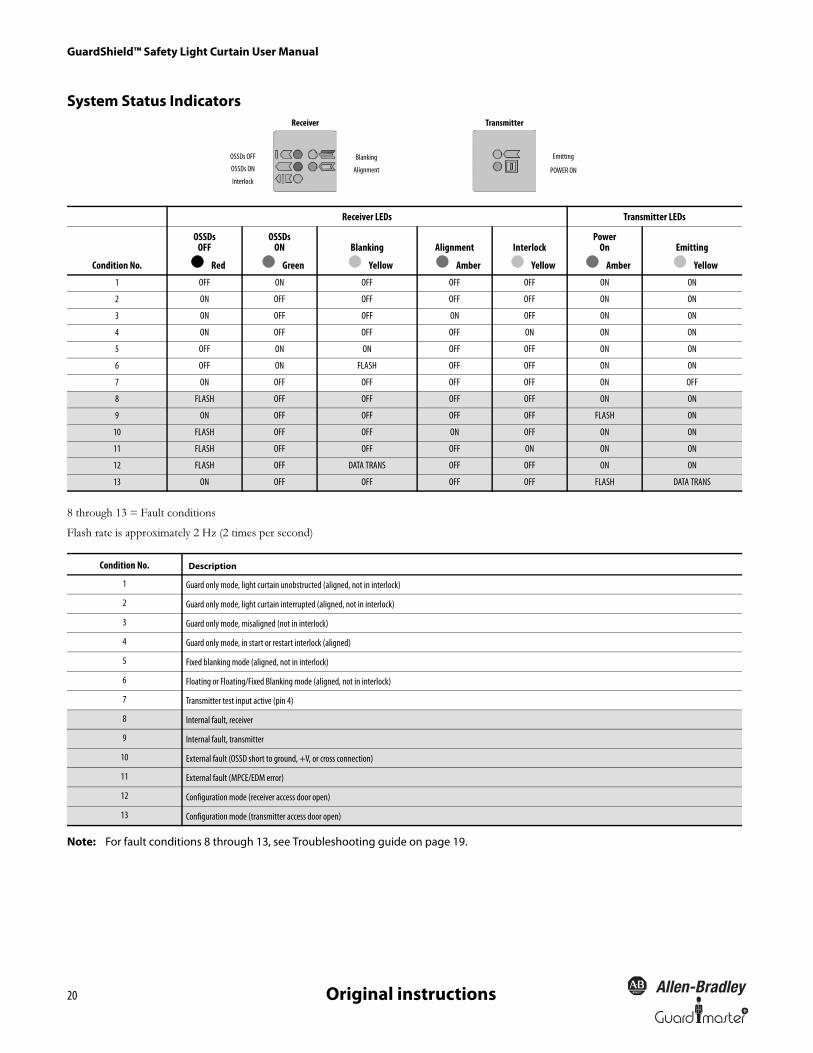
System Status Indicators
8 through 13 = Fault conditions
Flash rate is approximately 2 Hz (2 times per second)
Note: For fault conditions 8 through 13, see Troubleshooting guide on page 19.
Receiver LEDs Transmitter LEDs
Condition No.
OSSDsOFF
Red
OSSDsON
Green
Blanking
Yellow
Alignment
Amber
Interlock
Yellow
PowerOn
Amber
Emitting
Yellow
1 OFF ON OFF OFF OFF ON ON
2 ON OFF OFF OFF OFF ON ON
3 ON OFF OFF ON OFF ON ON
4 ON OFF OFF OFF ON ON ON
5 OFF ON ON OFF OFF ON ON
6 OFF ON FLASH OFF OFF ON ON
7 ON OFF OFF OFF OFF ON OFF
8 FLASH OFF OFF OFF OFF ON ON
9 ON OFF OFF OFF OFF FLASH ON
10 FLASH OFF OFF ON OFF ON ON
11 FLASH OFF OFF OFF ON ON ON
12 FLASH OFF DATA TRANS OFF OFF ON ON
13 ON OFF OFF OFF OFF FLASH DATA TRANS
Condition No. Description
1 Guard only mode, light curtain unobstructed (aligned, not in interlock)
2 Guard only mode, light curtain interrupted (aligned, not in interlock)
3 Guard only mode, misaligned (not in interlock)
4 Guard only mode, in start or restart interlock (aligned)
5 Fixed blanking mode (aligned, not in interlock)
6 Floating or Floating/Fixed Blanking mode (aligned, not in interlock)
7 Transmitter test input active (pin 4)
8 Internal fault, receiver
9 Internal fault, transmitter
10 External fault (OSSD short to ground, +V, or cross connection)
11 External fault (MPCE/EDM error)
12 Configuration mode (receiver access door open)
13 Configuration mode (transmitter access door open)
Receiver Transmitter
OSSDs OFF Blanking Emitting
OSSDs ON
InterlockAlignment POWER ON

R
GuardShield™ Safety Light Curtain User Manual
21Original instructions
ChecklistBefore the initiation of the GuardShield the responsible person should
work through the following checklist.
Cable check prior to initiation:
Switch the GuardShield on and check its function by observing the following:
Safety Instructions—Maintenance
Note:
1. For safety reasons all inspection results should be recorded.
2. Only persons, who clearly understand the functioning of the
GuardShield and of the machine, may carry out an inspection.
3. If installer, planning engineer and operator are different people,
make sure that the user has sufficient information available to carry
out the inspection.
Daily Inspection
Operate the machine and check, if the hazardous movement will stop
under the following circumstances.
1. o The power supply is solely connected to the GuardShield.
2. o The power supply is a 24V DC device, that must comply to
all applicable standards of the Machinery Directive 2006/
42/EC, and the product standard (IEC 61496).
3. o Proper polarity of the power supply at the GuardShield.
4. o The transmitter connection cable is properly connected to
the transmitter, the receiver connection cable is properly
connected to the receiver.
5. o The double insulation between the light curtain output and
an external potential is ensured.
6. o The OSSD outputs are not connected to +24V DC.
7. o The connected switching elements (load) are not connected
to 24V DC.
8. o No connection to a conventional power supply.
9. o If two or more GuardShield are to be used, make sure that
each system is properly installed, in order to avoid optical
interference.
10. o Two seconds after switching on, the system starts to work
properly, if the protective field is free of obstructions.
ATTENTIONAssure that all power to the machine, and safety system is disconnected during electrical installation.
Prior to powering up the GuardShield system, the responsible person should review the following Checklist.
IMPORTANT
1. o Approach to hazardous machine parts must only be
possible through passage through the protective field of
GuardShield.
2. o Operators cannot step through the sensing area while
working on dangerous machine parts.
3. o The safety distance of the application is bigger than the
calculated value.
4. o The optic front cover is neither scratched nor dirty.
5. o The protective field is interrupted.
6. o Hazardous machine movement stops immediately, if the
protective field is interrupted by the test rod directly in
front of the transmitter, directly in front of the receiver and
in the middle between transmitter and receiver.
7. o No hazardous machine movement while the test rod is
anywhere within the protective field.
8. o The power supply of the GuardShield is turned off.
9. o If the blanking function is activated, check all sections of
the protective field with the appropriate test piece.
Never operate the GuardShield before carrying out the following inspection. Improper inspection can lead to serious or even deadly injury.
ATTENTION
If any of the above conditions do not result in the hazardous motion of the machine ceasing, do not allow the protected machine to be placed in operation.
IMPORTANT
GuardShield™ Safety Light Curtain User Manual
22 R
Original instructions
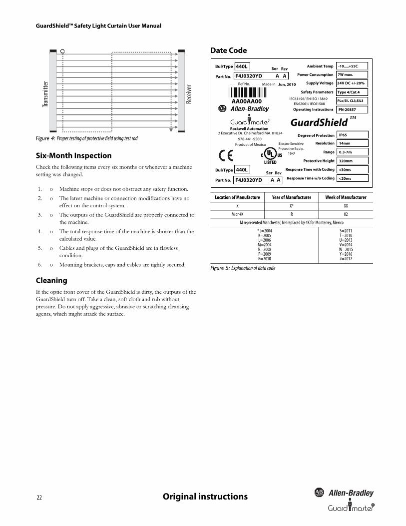
Figure 4: Proper testing of protective field using test rod
Six-Month InspectionCheck the following items every six months or whenever a machine
setting was changed.
CleaningIf the optic front cover of the GuardShield is dirty, the outputs of the
GuardShield turn off. Take a clean, soft cloth and rub without
pressure. Do not apply aggressive, abrasive or scratching cleansing
agents, which might attack the surface.
Date Code
Figure 5: Explanation of data code
1. o Machine stops or does not obstruct any safety function.
2. o The latest machine or connection modifications have no
effect on the control system.
3. o The outputs of the GuardShield are properly connected to
the machine.
4. o The total response time of the machine is shorter than the
calculated value.
5. o Cables and plugs of the GuardShield are in flawless
condition.
6. o Mounting brackets, caps and cables are tightly secured.
Trans
mitt
er
Rece
iver
Location of Manufacture Year of Manufacturer Week of Manufacturer
X X* XX
M or 4K R 02
M represented Manchester, NH replaced by 4K for Monterrey, Mexico
* J=2004K=2005L=2006M=2007N=2008P=2009R=2010
S=2011T=2010U=2013V=2014W=2015Y=2016Z=2017
Part No.
GuardShieldTM
PLe/SIL CL3,SIL3
Response Time w/o Coding
Protective Height
Range
Resolution
2 Executive Dr. Chelmsford MA. 01824
Product of Mexico978-441-9500
Ser Rev
F4J0320YD A A
Ser Rev440LBul/Type
Part No. F4J0320YD A A
AA00AA00
Ambient Temp
Power Consumption
Supply Voltage
Safety Parameters
Operating Instructions
Ref No. Jun, 2010
PN-20857
7W max.
IP65
14mm
0.3-7m
320mm
<30ms
<20ms
-10.....+55C
24V DC +/-20%
Bul/Type Response Time with Coding
Electro-SensitiveProtective Equip.
19KP
Degree of Protection
Rockwell Automation
440L
IEC61496/ EN ISO 13849EN62061/ IEC61508
Type 4/Cat.4
Made in
R
GuardShield™ Safety Light Curtain User Manual
23Original instructions
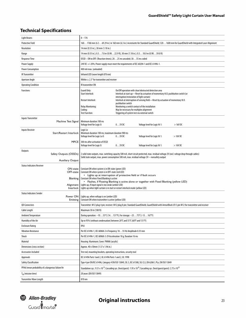
Technical SpecificationsLight Beams 8 – 176
Protective Field 160…1760 mm (6.3…69.29 in.) in 160 mm (6.3 in.) increments for Standard GuardShield; 320…1600 mm for GuardShield with Integrated Laser Alignment
Resolution 14 mm (0.55 in.), 30 mm (1.18 in.)
Range 14 mm (0.55 in.); 0.3…7.0 m (0.98…22.9 ft), 30 mm (1.18 in.); 0.3…18.0 m (0.98…59.0 ft)
Response Time OSSD – ON to OFF: (Reaction times); 20…25 ms uncoded; 30…35 ms coded
Power Supply 24V DC +/-20%; Power supply must meet the requirements of IEC 60204-1 and IEC 61496-1.
Power Consumption 400 mA max. (unloaded)
IR Transmitter Infrared LED (wave length 870 nm)
Aperture Angle Within ± 2.5° for transmitter and receiver
Operating Condition IR transmitter ON
Functions Guard Only: On/Off operation with clear/obstructed detection areaStart Interlock: Interlock at start up—Reset by actuation of momentary N.O. pushbutton switch (or
interruption/restoration of light curtain)Restart Interlock: Interlock at interruption of sensing field—Reset by actuation of momentary N.O.
pushbutton switchRelay Monitoring: Monitoring a switch contact of the installationCoding: May be necessary for multiplex alignmentTest Function: Triggering of system test via external switch
Inputs TransmitterMachine Test Signal Minimum duration 100 ms
Voltage level for Logic 0: 0…5V DC Voltage level for Logic Hi 1: > 16V DC
Inputs ReceiverStart/Restart Interlock
Logic LoMinimum duration 100 ms; maximum duration 900 msVoltage level for Logic Lo 0: 0…5V DC Voltage level for Logic Hi 1: > 16V DC
MPCE 300 ms after activation of OSSDVoltage level for Logic 0: 0…5V DC Voltage level for Logic Hi 1: > 16V DC
Outputs:Safety Outputs (OSSDs)
Auxiliary Output
2 solid state outputs, max. switching capacity 500 mA, short circuit protected, max. residual voltage 2V (excl. voltage drop through cables)Solid state output, max. power consumption 500 mA, max. residual voltage 2V—nonsafety output
Status Indicators ReceiverON-stateOFF-state
Blanking
AlignmentInterlock
Constant ON when system is in ON-state (green LED) Constant ON when system is in OFF-state (red LED)
• Lights up at interruption of protective field or if fault occurs Constant ON when Fixed Blanking is active
• Flashes, if Floating Blanking is active alone or together with Fixed Blanking (yellow LED) Lights up, if input signal is too weak (amber LED)Lights up when light curtain is in start or restart interlock mode (yellow LED)
Status Indicators SenderPower ON
EmittingLights up, when voltage is on (amber LED)Constant ON when transmitter is active (yellow LED)
QD Connectors Transmitter: M12 plug 4 pin; receiver: M12 plug 8 pin; Standard GuardShield, GuardShield with ArmorBlock I/O 5 pin M12 for transmitter and receiver
Cable Length Maximum 30 m (100 ft)
Ambient Temperature During operation: –10…55°C (14…131°F); For storage: –25…75°C (-13…167°F)
Humidity of the Air Up to 95% (without condensation) between 20°C and 55°C (68°F and 131°F)
Enclosure Rating IP65
Vibration Resistance Per IEC 61496-1, IEC 60068-2-6 Frequency 10…55 Hz Amplitude 0.35 mm
Shock Per IEC 61496-1, IEC 60068-2-29 Acceleration 10 g, Duration 16 ms
Material Housing: Aluminum; Cover: PMMA (acrylic)
Dimensions (cross section) Approx. 40 x 50mm (1.57 x 1.96 in.)
Accessories Included Test rod, mounting brackets, operating instructions, security tool
Approvals IEC 61496 Parts 1and 2, UL 61496 Parts 1 and 2, UL 1998
Safety Classification Type 4 per EN/IEC 61496, Category 4 EN/ISO 13849, SIL 3, IEC 61508, SIL CL3, EN 62061, PLe, EN/ISO 13849
PFHd (mean probability of a dangerous failure/hr Standalone sys.: 9.51 x 10⁻⁹; Cascading sys. (host/guest): 1.95 x 10⁻⁸; Cascading sys. (host/guest/guest): 2.75 x 10⁻⁸
TM (mission time) 20 years (EN ISO 13849)
Transmitter Wave Length 870 nm
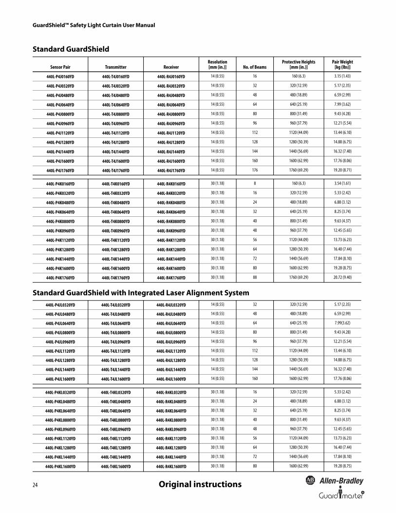
GuardShield™ Safety Light Curtain User Manual
24 R
Original instructions
Standard GuardShield
Standard GuardShield with Integrated Laser Alignment System
Sensor Pair Transmitter ReceiverResolution[mm (in.)] No. of Beams
Protective Heights[mm (in.)]
Pair Weight[kg (lbs)]
440L-P4J0160YD 440L-T4J0160YD 440L-R4J0160YD 14 (0.55) 16 160 (6.3) 3.15 (1.43)
440L-P4J0320YD 440L-T4J0320YD 440L-R4J0320YD 14 (0.55) 32 320 (12.59) 5.17 (2.35)
440L-P4J0480YD 440L-T4J0480YD 440L-R4J0480YD 14 (0.55) 48 480 (18.89) 6.59 (2.99)
440L-P4J0640YD 440L-T4J0640YD 440L-R4J0640YD 14 (0.55) 64 640 (25.19) 7.99 (3.62)
440L-P4J0800YD 440L-T4J0800YD 440L-R4J0800YD 14 (0.55) 80 800 (31.49) 9.43 (4.28)
440L-P4J0960YD 440L-T4J0960YD 440L-R4J0960YD 14 (0.55) 96 960 (37.79) 12.21 (5.54)
440L-P4J1120YD 440L-T4J1120YD 440L-R4J1120YD 14 (0.55) 112 1120 (44.09) 13.44 (6.10)
440L-P4J1280YD 440L-T4J1280YD 440L-R4J1280YD 14 (0.55) 128 1280 (50.39) 14.88 (6.75)
440L-P4J1440YD 440L-T4J1440YD 440L-R4J1440YD 14 (0.55) 144 1440 (56.69) 16.32 (7.40)
440L-P4J1600YD 440L-T4J1600YD 440L-R4J1600YD 14 (0.55) 160 1600 (62.99) 17.76 (8.06)
440L-P4J1760YD 440L-T4J1760YD 440L-R4J1760YD 14 (0.55) 176 1760 (69.29) 19.20 (8.71)
440L-P4K0160YD 440L-T4K0160YD 440L-R4K0160YD 30 (1.18) 8 160 (6.3) 3.54 (1.61)
440L-P4K0320YD 440L-T4K0320YD 440L-R4K0320YD 30 (1.18) 16 320 (12.59) 5.33 (2.42)
440L-P4K0480YD 440L-T4K0480YD 440L-R4K0480YD 30 (1.18) 24 480 (18.89) 6.88 (3.12)
440L-P4K0640YD 440L-T4K0640YD 440L-R4K0640YD 30 (1.18) 32 640 (25.19) 8.25 (3.74)
440L-P4K0800YD 440L-T4K0800YD 440L-R4K0800YD 30 (1.18) 40 800 (31.49) 9.63 (4.37)
440L-P4K0960YD 440L-T4K0960YD 440L-R4K0960YD 30 (1.18) 48 960 (37.79) 12.45 (5.65)
440L-P4K1120YD 440L-T4K1120YD 440L-R4K1120YD 30 (1.18) 56 1120 (44.09) 13.73 (6.23)
440L-P4K1280YD 440L-T4K1280YD 440L-R4K1280YD 30 (1.18) 64 1280 (50.39) 16.40 (7.44)
440L-P4K1440YD 440L-T4K1440YD 440L-R4K1440YD 30 (1.18) 72 1440 (56.69) 17.84 (8.10)
440L-P4K1600YD 440L-T4K1600YD 440L-R4K1600YD 30 (1.18) 80 1600 (62.99) 19.28 (8.75)
440L-P4K1760YD 440L-T4K1760YD 440L-R4K1760YD 30 (1.18) 88 1760 (69.29) 20.72 (9.40)
440L-P4JL0320YD 440L-T4JL0320YD 440L-R4JL0320YD 14 (0.55) 32 320 (12.59) 5.17 (2.35)
440L-P4JL0480YD 440L-T4JL0480YD 440L-R4JL0480YD 14 (0.55) 48 480 (18.89) 6.59 (2.99)
440L-P4JL0640YD 440L-T4JL0640YD 440L-R4JL0640YD 14 (0.55) 64 640 (25.19) 7.99(3.62)
440L-P4JL0800YD 440L-T4JL0800YD 440L-R4JL0800YD 14 (0.55) 80 800 (31.49) 9.43 (4.28)
440L-P4JL0960YD 440L-T4JL0960YD 440L-R4JL0960YD 14 (0.55) 96 960 (37.79) 12.21 (5.54)
440L-P4JL1120YD 440L-T4JL1120YD 440L-R4JL1120YD 14 (0.55) 112 1120 (44.09) 13.44 (6.10)
440L-P4JL1280YD 440L-T4JL1280YD 440L-R4JL1280YD 14 (0.55) 128 1280 (50.39) 14.88 (6.75)
440L-P4JL1440YD 440L-T4JL1440YD 440L-R4JL1440YD 14 (0.55) 144 1440 (56.69) 16.32 (7.40)
440L-P4JL1600YD 440L-T4JL1600YD 440L-R4JL1600YD 14 (0.55) 160 1600 (62.99) 17.76 (8.06)
440L-P4KL0320YD 440L-T4KL0320YD 440L-R4KL0320YD 30 (1.18) 16 320 (12.59) 5.33 (2.42)
440L-P4KL0480YD 440L-T4KL0480YD 440L-R4KL0480YD 30 (1.18) 24 480 (18.89) 6.88 (3.12)
440L-P4KL0640YD 440L-T4KL0640YD 440L-R4KL0640YD 30 (1.18) 32 640 (25.19) 8.25 (3.74)
440L-P4KL0800YD 440L-T4KL0800YD 440L-R4KL0800YD 30 (1.18) 40 800 (31.49) 9.63 (4.37)
440L-P4KL0960YD 440L-T4KL0960YD 440L-R4KL0960YD 30 (1.18) 48 960 (37.79) 12.45 (5.65)
440L-P4KL1120YD 440L-T4KL1120YD 440L-R4KL1120YD 30 (1.18) 56 1120 (44.09) 13.73 (6.23)
440L-P4KL1280YD 440L-T4KL1280YD 440L-R4KL1280YD 30 (1.18) 64 1280 (50.39) 16.40 (7.44)
440L-P4KL1440YD 440L-T4KL1440YD 440L-R4KL1440YD 30 (1.18) 72 1440 (56.69) 17.84 (8.10)
440L-P4KL1600YD 440L-T4KL1600YD 440L-R4KL1600YD 30 (1.18) 80 1600 (62.99) 19.28 (8.75)

GuardShield™ Safety Light Curtain User Manual
25R
Original instructions
Standard GuardShield with Integrated Laser Alignment and ArmorBlock I/O Connection
Cascading GuardShield
Sensor Pair Transmitter ReceiverResolution [mm
(in.)] No. of BeamsProtective Heights
[mm (in.)]Pair Weight
[kg (lbs)]
440L-P4JL0320YA 440L-T4JL0320YA 440L-R4JL0320YA 14 (0.55) 32 320 (12.59) 5.17 (2.35)
440L-P4JL0480YA 440L-T4JL0480YA 440L-R4JL0480YA 14 (0.55) 48 480 (18.89) 6.59 (2.99)
440L-P4JL0640YA 440L-T4JL0640YA 440L-R4JL0640YA 14 (0.55) 64 640 (25.19) 7.99(3.62)
440L-P4JL0800YA 440L-T4JL0800YA 440L-R4JL0800YA 14 (0.55) 80 800 (31.49) 9.43 (4.28)
440L-P4JL0960YA 440L-T4JL0960YA 440L-R4JL0960YA 14 (0.55) 96 960 (37.79) 12.21 (5.54)
440L-P4JL1120YA 440L-T4JL1120YA 440L-R4JL1120YA 14 (0.55) 112 1120 (44.09) 13.44 (6.10)
440L-P4JL1280YA 440L-T4JL1280YA 440L-R4JL1280YA 14 (0.55) 128 1280 (50.39) 14.88 (6.75)
440L-P4JL1440YA 440L-T4JL1440YA 440L-R4JL1440YA 14 (0.55) 144 1440 (56.69) 16.32 (7.40)
440L-P4JL1600YA 440L-T4JL1600YA 440L-R4JL1600YA 14 (0.55) 160 1600 (62.99) 17.76 (8.06)
440L-P4KL0320YA 440L-T4KL0320YA 440L-R4KL0320YA 30 (1.18) 16 320 (12.59) 5.33 (2.42)
440L-P4KL0480YA 440L-T4KL0480YA 440L-R4KL0480YA 30 (1.18) 24 480 (18.89) 6.88 (3.12)
440L-P4KL0640YA 440L-T4KL0640YA 440L-R4KL0640YA 30 (1.18) 32 640 (25.19) 8.25 (3.74)
440L-P4KL0800YA 440L-T4KL0800YA 440L-R4KL0800YA 30 (1.18) 40 800 (31.49) 9.63 (4.37)
440L-P4KL0960YA 440L-T4KL0960YA 440L-R4KL0960YA 30 (1.18) 48 960 (37.79) 12.45 (5.65)
440L-P4KL1120YA 440L-T4KL1120YA 440L-R4KL1120YA 30 (1.18) 56 1120 (44.09) 13.73 (6.23)
440L-P4KL1280YA 440L-T4KL1280YA 440L-R4KL1280YA 30 (1.18) 64 1280 (50.39) 16.40 (7.44)
440L-P4KL1440YA 440L-T4KL1440YA 440L-R4KL1440YA 30 (1.18) 72 1440 (56.69) 17.84 (8.10)
440L-P4KL1600YA 440L-T4KL1600YA 440L-R4KL1600YA 30 (1.18) 80 1600 (62.99) 19.28 (8.75)
440L-C4J0320YD 440L-G4J0320YD 440L-F4J0320YD 14 (0.55) 32 320 (12.59) 5.17 (2.35)
440L-C4J0480YD 440L-G4J0480YD 440L-F4J0480YD 14 (0.55) 48 480 (18.89) 6.59 (2.99)
440L-C4J0640YD 440L-G4J0640YD 440L-F4J0640YD 14 (0.55) 64 640 (25.19) 7.99 (3.62)
440L-C4J0800YD 440L-G4J0800YD 440L-F4J0800YD 14 (0.55) 80 800 (31.49) 9.43 (4.28)
440L-C4J0960YD 440L-G4J0960YD 440L-F4J0960YD 14 (0.55) 96 960 (37.79) 12.21 (5.54)
440L-C4J1120YD 440L-G4J1120YD 440L-F4J1120YD 14 (0.55) 112 1120 (44.09) 13.44 (6.10)
440L-C4J1280YD 440L-G4J1280YD 440L-F4J1280YD 14 (0.55) 128 1280 (50.39) 14.88 (6.75)
440L-C4J1440YD 440L-G4J1440YD 440L-F4J1440YD 14 (0.55) 144 1440 (56.69) 16.32 (7.40)
440L-C4J1600YD 440L-G4J1600YD 440L-F4J1600YD 14 (0.55) 160 1600 (62.99) 17.76 (8.06)
440L-C4J1760YD 440L-G4J1760YD 440L-F4J1760YD 14 (0.55) 176 1760 (69.29) 19.20 (8.71)
440L-C4K0320YD 440L-G4K0320YD 440L-F4K0320YD 30 (1.18) 16 320 (12.59) 5.33 (2.42)
440L-C4K0480YD 440L-G4K0480YD 440L-F4K0480YD 30 (1.18) 24 480 (18.89) 6.88 (3.12)
440L-C4K0640YD 440L-G4K0640YD 440L-F4K0640YD 30 (1.18) 32 640 (25.19) 8.25 (3.74)
440L-C4K0800YD 440L-G4K0800YD 440L-F4K0800YD 30 (1.18) 40 800 (31.49) 9.63 (4.37)
440L-C4K0960YD 440L-G4K0960YD 440L-F4K0960YD 30 (1.18) 48 960 (37.79) 12.45 (5.65)
440L-C4K1120YD 440L-G4K1120YD 440L-F4K1120YD 30 (1.18) 56 1120 (44.09) 13.73 (6.23)
440L-C4K1280YD 440L-G4K1280YD 440L-F4K1280YD 30 (1.18) 64 1280 (50.39) 16.40 (7.44)
440L-C4K1440YD 440L-G4K1440YD 440L-F4K1440YD 30 (1.18) 72 1440 (56.69) 17.84 (8.10)
440L-C4K1600YD 440L-G4K1600YD 440L-F4K1600YD 30 (1.18) 80 1600 (62.99) 19.28 (8.75)
440L-C4K1760YD 440L-G4K1760YD 440L-F4K1760YD 30 (1.18) 88 1760 (69.29) 20.72 (9.40)

GuardShield™ Safety Light Curtain User Manual
26 R
Original instructions
Cascading GuardShield with Integrated Laser Alignment
Cascading GuardShield with Integrated Laser Alignment and ArmorBlock IO Connection
Sensor Pair Transmitter ReceiverResolution [mm
(in.)] No. of BeamsProtective Heights
[mm (in.)]Pair Weight
[kg (lbs)]
440L-C4JL0320YD 440L-G4JL0320YD 440L-F4JL0320YD 14 (0.55) 32 320 (12.59) 5.17 (2.35)
440L-C4JL0480YD 440L-G4JL0480YD 440L-F4JL0480YD 14 (0.55) 48 480 (18.89) 6.59 (2.99)
440L-C4JL0640YD 440L-G4JL0640YD 440L-F4JL0640YD 14 (0.55) 64 640 (25.19) 7.99(3.62)
440L-C4JL0800YD 440L-G4JL0800YD 440L-F4JL0800YD 14 (0.55) 80 800 (31.49) 9.43 (4.28)
440L-C4JL0960YD 440L-G4JL0960YD 440L-F4JL0960YD 14 (0.55) 96 960 (37.79) 12.21 (5.54)
440L-C4JL1120YD 440L-G4JL1120YD 440L-F4JL1120YD 14 (0.55) 112 1120 (44.09) 13.44 (6.10)
440L-C4JL1280YD 440L-G4JL1280YD 440L-F4JL1280YD 14 (0.55) 128 1280 (50.39) 14.88 (6.75)
440L-C4JL1440YD 440L-G4JL1440YD 440L-F4JL1440YD 14 (0.55) 144 1440 (56.69) 16.32 (7.40)
440L-C4JL1600YD 440L-G4JL1600YD 440L-F4JL1600YD 14 (0.55) 160 1600 (62.99) 17.76 (8.06)
440L-C4KL0320YD 440L-G4KL0320YD 440L-F4KL0320YD 30 (1.18) 16 320 (12.59) 5.33 (2.42)
440L-C4KL0480YD 440L-G4KL0480YD 440L-F4KL0480YD 30 (1.18) 24 480 (18.89) 6.88 (3.12)
440L-C4KL0640YD 440L-G4KL0640YD 440L-F4KL0640YD 30 (1.18) 32 640 (25.19) 8.25 (3.74)
440L-C4KL0800YD 440L-G4KL0800YD 440L-F4KL0800YD 30 (1.18) 40 800 (31.49) 9.63 (4.37)
440L-C4KL0960YD 440L-G4KL0960YD 440L-F4KL0960YD 30 (1.18) 48 960 (37.79) 12.45 (5.65)
440L-C4KL1120YD 440L-G4KL1120YD 440L-F4KL1120YD 30 (1.18) 56 1120 (44.09) 13.73 (6.23)
440L-C4KL1280YD 440L-G4KL1280YD 440L-F4KL1280YD 30 (1.18) 64 1280 (50.39) 16.40 (7.44)
440L-C4KL1440YD 440L-G4KL1440YD 440L-F4KL1440YD 30 (1.18) 72 1440 (56.69) 17.84 (8.10)
440L-C4KL1600YD 440L-G4KL1600YD 440L-F4KL1600YD 30 (1.18) 80 1600 (62.99) 19.28 (8.75)
440L-C4JL0320YA 440L-G4JL0320YA 440L-F4JL0320YA 14 (0.55) 32 320 (12.59) 5.17 (2.35)
440L-C4JL0480YA 440L-G4JL0480YA 440L-F4JL0480YA 14 (0.55) 48 480 (18.89) 6.59 (2.99)
440L-C4JL0640YA 440L-G4JL0640YA 440L-F4JL0640YA 14 (0.55) 64 640 (25.19) 7.99(3.62)
440L-C4JL0800YA 440L-G4JL0800YA 440L-F4JL0800YA 14 (0.55) 80 800 (31.49) 9.43 (4.28)
440L-C4JL0960YA 440L-G4JL0960YA 440L-F4JL0960YA 14 (0.55) 96 960 (37.79) 12.21 (5.54)
440L-C4JL1120YA 440L-G4JL1120YA 440L-F4JL1120YA 14 (0.55) 112 1120 (44.09) 13.44 (6.10)
440L-C4JL1280YA 440L-G4JL1280YA 440L-F4JL1280YA 14 (0.55) 128 1280 (50.39) 14.88 (6.75)
440L-C4JL1440YA 440L-G4JL1440YA 440L-F4JL1440YA 14 (0.55) 144 1440 (56.69) 16.32 (7.40)
440L-C4JL1600YA 440L-G4JL1600YA 440L-F4JL1600YA 14 (0.55) 160 1600 (62.99) 17.76 (8.06)
440L-C4KL0320YA 440L-G4KL0320YA 440L-F4KL0320YA 30 (1.18) 16 320 (12.59) 5.33 (2.42)
440L-C4KL0480YA 440L-G4KL0480YA 440L-F4KL0480YA 30 (1.18) 24 480 (18.89) 6.88 (3.12)
440L-C4KL0640YA 440L-G4KL0640YA 440L-F4KL0640YA 30 (1.18) 32 640 (25.19) 8.25 (3.74)
440L-C4KL0800YA 440L-G4KL0800YA 440L-F4KL0800YA 30 (1.18) 40 800 (31.49) 9.63 (4.37)
440L-C4KL0960YA 440L-G4KL0960YA 440L-F4KL0960YA 30 (1.18) 48 960 (37.79) 12.45 (5.65)
440L-C4KL1120YA 440L-G4KL1120YA 440L-F4KL1120YA 30 (1.18) 56 1120 (44.09) 13.73 (6.23)
440L-C4KL1280YA 440L-G4KL1280YA 440L-F4KL1280YA 30 (1.18) 64 1280 (50.39) 16.40 (7.44)
440L-C4KL1440YA 440L-G4KL1440YA 440L-F4KL1440YA 30 (1.18) 72 1440 (56.69) 17.84 (8.10)
440L-C4KL1600YA 440L-G4KL1600YA 440L-F4KL1600YA 30 (1.18) 80 1600 (62.99) 19.28 (8.75)

GuardShield™ Safety Light Curtain User Manual
27R
Original instructions
Cat. No. Explanation—Standard and Cascading GuardShield without Laser Alignment System
Cat. No. Explanation—GuardShield with Integrated Laser Alignment System
440L - P 4 J 03 20 Y DConnector Option Micro QD
Environmental Rating IP65
14 mm (0.55 in.) GuardShield K - 30 mm (1.18 in.) GuardShield
Category Type 4
P - Pair, T - Transmitter, R - Receiver, (Standard)C - Host, Pair, G - Host Transmitter, F - Host Receiver (cascading)
Bulletin Number
0160 - Protective Height03200480 0960 14400640 1120 16000800 1280 1760
R-Remote Teach Pigtail ConnectorA-ArmorBlock Safety I/O Connector(M12, 5 pin
440L - P 4 K L 0320 Y DConnector Option
Environmental Rating IP65
L = Integrated Laser Alignment System
Category Type 4
P = Pair, T = Transmitter, R = ReceiverC = Cascade pair, G = Cascade transmitter, F = Cascade receiver
Bulletin Number
Protective Height03200480 0960 14400640 1120 16000800 1280
D-Standard 5 pin M12 XMTR 18 pin M12 receiverA-5 pin M12 for ArmorBlock Safety I/O connector
K=30 mm resolution; J=14 mm resolution

GuardShield™ Safety Light Curtain User Manual
28 R
Original instructions
Dimensions [mm (in.)]
� J or K� P, T, R, C, G, F� D or R
TypeA
Protective HeightB
Mounting ValueC
Total Length
440L-�4�0160Y� 160 ±0.5 (6.3) ±0.02 276 (10.9) 312 ±1.5 (12.3) ±0.06
440L-�4�0320Y� 320 ±0.5 (12.6) ±0.02 436 (17.2) 472 ±1.5 (18.6) ±0.06
440L-�4�0480Y� 480 ±0.5 (18.9) ±0.02 596 (28.5) 632 ±1.5 (24.9) ±0.06
440L-�4�0640Y� 640 ±0.5 (25.2) ±0.02 756 (29.8) 792 ±1.5 (31.2) ±0.06
440L-�4�0800Y� 800 ±0.6 (31.5) ±0.02 916 (36.1) 952 ±1.5 (37.5) ±0.06
440L-�4�0960Y� 960 ±0.6 (37.8) ±0.02 1076 (42.4) 1112 ±1.5 (43.8) ±0.06
440L-�4�1120Y� 1120 ±0.6 (44.1) ±0.02 1236 (48.7) 1272 ±1.8 (50.1) ±0.07
440L-�4�1280Y� 1280 ±0.7 (50.4) ±0.02 1396 (55.0) 1432 ±1.8 (56.4) ±0.07
440L-�4�1440Y� 1440 ±0.7 (56.7) ±0.03 1556 (61.3) 1592 ±1.8 (62.7) ±0.07
440L-�4�1600Y� 1600 ±0.8 (63.0) ±0.03 1716 (67.6) 1752 ±2.0 (69.0) ±0.08
440L-�4�1760Y� 1760 ±0.8 (69.3) ±0.03 1876 (73.9) 1912 ±2.0 (75.3) ±0.08
C B A
40(1.57)
42(1.65)
20(0.79)
75(2.95)
52(2.05)
11(0.43)
80(3.14) min.
To be used invibration applications
52(2.05)
11(0.43)
80(3.14) min.
32(1.25)
80(3.14) min.
Standard Cascading
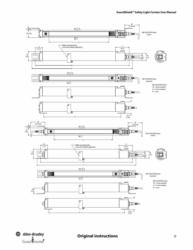
GuardShield™ Safety Light Curtain User Manual
29R
Original instructions
11 (0.48)
42 (1.65)
80(3.14) min.
440L-R4JL0320YD shownreceiver
75(2.95)
20(0.79)
40(1.57)
A
Middle mounting bracketto be used in vibration applications
B
C
52(2.05)
40(1.57)
440L-T4JL0320YD showntransmitter
440L-P4JL0320YD shown K = 30 mm resolution J = 14 mm resolution L = Laser
63.5(2.50)D
11 (0.48)
42(1.65)
80(3.14) min.
440L-F4JL0320YD shownreceiver
75(2.95)
20(0.79)
40(1.57)
A
Middle mounting bracketto be used in vibration applications
B
C
52(2.05)
40(1.57)
440L-G4JL0320YD showntransmitter
440L-C4JL0320YD shown K = 30 mm resolution J = 14 mm resolution L = Laser
63.5(2.50)
80(3.14) min.
D
32(1.25)
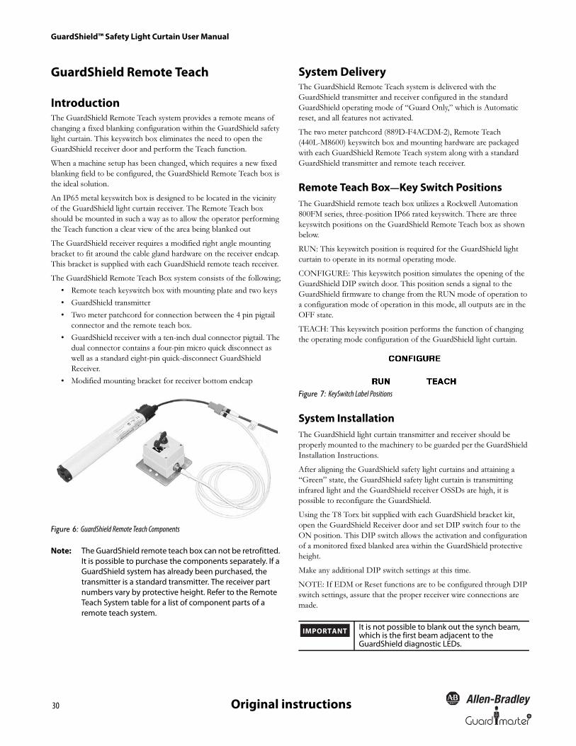
GuardShield™ Safety Light Curtain User Manual
30 R
Original instructions
GuardShield Remote Teach
IntroductionThe GuardShield Remote Teach system provides a remote means of
changing a fixed blanking configuration within the GuardShield safety
light curtain. This keyswitch box eliminates the need to open the
GuardShield receiver door and perform the Teach function.
When a machine setup has been changed, which requires a new fixed
blanking field to be configured, the GuardShield Remote Teach box is
the ideal solution.
An IP65 metal keyswitch box is designed to be located in the vicinity
of the GuardShield light curtain receiver. The Remote Teach box
should be mounted in such a way as to allow the operator performing
the Teach function a clear view of the area being blanked out
The GuardShield receiver requires a modified right angle mounting
bracket to fit around the cable gland hardware on the receiver endcap.
This bracket is supplied with each GuardShield remote teach receiver.
The GuardShield Remote Teach Box system consists of the following;
• Remote teach keyswitch box with mounting plate and two keys
• GuardShield transmitter
• Two meter patchcord for connection between the 4 pin pigtail
connector and the remote teach box.
• GuardShield receiver with a ten-inch dual connector pigtail. The
dual connector contains a four-pin micro quick disconnect as
well as a standard eight-pin quick-disconnect GuardShield
Receiver.
• Modified mounting bracket for receiver bottom endcap
Figure 6: GuardShield Remote Teach Components
Note: The GuardShield remote teach box can not be retrofitted. It is possible to purchase the components separately. If a GuardShield system has already been purchased, the transmitter is a standard transmitter. The receiver part numbers vary by protective height. Refer to the Remote Teach System table for a list of component parts of a remote teach system.
System DeliveryThe GuardShield Remote Teach system is delivered with the
GuardShield transmitter and receiver configured in the standard
GuardShield operating mode of “Guard Only,” which is Automatic
reset, and all features not activated.
The two meter patchcord (889D-F4ACDM-2), Remote Teach
(440L-M8600) keyswitch box and mounting hardware are packaged
with each GuardShield Remote Teach system along with a standard
GuardShield transmitter and remote teach receiver.
Remote Teach Box—Key Switch PositionsThe GuardShield remote teach box utilizes a Rockwell Automation
800FM series, three-position IP66 rated keyswitch. There are three
keyswitch positions on the GuardShield Remote Teach box as shown
below.
RUN: This keyswitch position is required for the GuardShield light
curtain to operate in its normal operating mode.
CONFIGURE: This keyswitch position simulates the opening of the
GuardShield DIP switch door. This position sends a signal to the
GuardShield firmware to change from the RUN mode of operation to
a configuration mode of operation in this mode, all outputs are in the
OFF state.
TEACH: This keyswitch position performs the function of changing
the operating mode configuration of the GuardShield light curtain.
Figure 7: KeySwitch Label Positions
System InstallationThe GuardShield light curtain transmitter and receiver should be
properly mounted to the machinery to be guarded per the GuardShield
Installation Instructions.
After aligning the GuardShield safety light curtains and attaining a
“Green” state, the GuardShield safety light curtain is transmitting
infrared light and the GuardShield receiver OSSDs are high, it is
possible to reconfigure the GuardShield.
Using the T8 Torx bit supplied with each GuardShield bracket kit,
open the GuardShield Receiver door and set DIP switch four to the
ON position. This DIP switch allows the activation and configuration
of a monitored fixed blanked area within the GuardShield protective
height.
Make any additional DIP switch settings at this time.
NOTE: If EDM or Reset functions are to be configured through DIP
switch settings, assure that the proper receiver wire connections are
made.
It is not possible to blank out the synch beam, which is the first beam adjacent to the GuardShield diagnostic LEDs.
IMPORTANT

R
GuardShield™ Safety Light Curtain User Manual
31Original instructions
Note: If the Transmitter’s configuration needs to be changed from the factory settings, set the DIP switches in the transmitter and follow the standard teach process
Remote Teach Procedure1. Position object in the GuardShield sensing field, assure that the
synchronization beam is not obstructed
2. Turn keyswitch to the configure position. The receiver’s red LED
will be flashing and the yellow blanking LED will be illuminated.
3. Turn and hold keyswitch in the Teach position
4. The GuardShield receiver’s yellow blanking LED will begin
flashing.
5. When the yellow blanking LED stops flashing, release the
keyswitch to the configure position within two seconds.
6. The GuardShield receiver’s yellow blanking LED will flash three
times to confirm that the new fixed blanking configuration has
been set.
7. Turn the keyswitch to the RUN position, the green LED on the
GuardShield receiver will illuminate.
8. Using the supplied test rod, confirm the fixed blanking area and any
other settings are configured as expected.
It is possible to configure and activate both fixed and one or two beam
floating blanking on the GuardShield light curtain.
NOTE: Once the GuardShield is configured by changing factory DIP
switch positions and performing the Teach function, the GuardShield
will be reconfigured. Any future Teach procedure will only change the
configuration of the fixed blanking area.
Remote Teach System
Remote Teach System Component Parts
IMPORTANTAfter teaching the GuardShield a new configuration, confirm that the configuration that was expected to be configured has actually been configured.
IMPORTANTFixed blanking creates a “hole” in the detection area of the GuardShield. It is necessary to assure that access to the hazard being protected against is prevented by means of barrier guarding. It should not be possible to access the hazard through the fixed blanked area.
Cat. No. Description
440L-S4J0160YR GuardShield Remote Teach system, 160 mm protective height 14 mm resolution
440L-S4J0320YR GuardShield Remote Teach system, 320 mm protective height 14 mm resolution
440L-S4J0480YR GuardShield Remote Teach system, 480 mm protective height 14 mm resolution
440L-S4J0640YR GuardShield Remote Teach system, 640 mm protective height 14 mm resolution
440L-S4J0800YR GuardShield Remote Teach system, 800 mm protective height 14 mm resolution
440L-S4J0960YR GuardShield Remote Teach system, 960mm protective height 14 mm resolution
440L-S4J1120YR GuardShield Remote Teach system, 1120 mm protective height 14 mm resolution
440L-S4J1280YR GuardShield Remote Teach system, 1280 mm protective height 14 mm resolution
440L-S4J1440YR GuardShield Remote Teach system, 1440 mm protective height 14 mm resolution
440L-S4J1600YR GuardShield Remote Teach system, 1600 mm protective height 14 mm resolution
440L-S4J1760YR GuardShield Remote Teach system, 1760 mm protective height 14 mm resolution
440L-S4K0160YR GuardShield Remote Teach system, 160 mm protective height 30 mm resolution
440L-S4K0320YR GuardShield Remote Teach system, 320 mm protective height 30 mm resolution
440L-S4K0480YR GuardShield Remote Teach system, 480 mm protective height 30 mm resolution
440L-S4K0640YR GuardShield Remote Teach system, 640 mm protective height 30 mm resolution
440L-S4K0800YR GuardShield Remote Teach system, 800 mm protective height 30 mm resolution
440L-S4K0960YR GuardShield Remote Teach system, 960mm protective height 30 mm resolution
440L-S4K1120YR GuardShield Remote Teach system, 1120 mm protective height 30 mm resolution
440L-S4K1280YR GuardShield Remote Teach system, 1280 mm protective height 30 mm resolution
440L-S4K1440YR GuardShield Remote Teach system, 1440 mm protective height 30 mm resolution
440L-S4K1600YR GuardShield Remote Teach system, 1600 mm protective height 30 mm resolution
440L-S4K1760YR GuardShield Remote Teach system, 1760 mm protective height 30 mm resolution
Catalog Number Description
800F-AKR3825 Replacement Key
440L-M8600 Remote Teach Box
889D-F4ACDM-2 Two meter patchcord
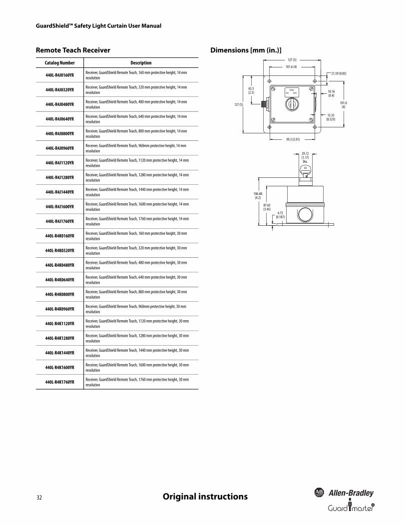
GuardShield™ Safety Light Curtain User Manual
32 R
Original instructions
Remote Teach Receiver Dimensions [mm (in.)]
Catalog Number Description
440L-R4J0160YR Receiver, GuardShield Remote Teach, 160 mm protective height, 14 mm resolution
440L-R4J0320YR Receiver, GuardShield Remote Teach, 320 mm protective height, 14 mm resolution
440L-R4J0480YR Receiver, GuardShield Remote Teach, 480 mm protective height, 14 mm resolution
440L-R4J0640YR Receiver, GuardShield Remote Teach, 640 mm protective height, 14 mm resolution
440L-R4J0800YR Receiver, GuardShield Remote Teach, 800 mm protective height, 14 mm resolution
440L-R4J0960YR Receiver, GuardShield Remote Teach, 960mm protective height, 14 mm resolution
440L-R4J1120YR Receiver, GuardShield Remote Teach, 1120 mm protective height, 14 mm resolution
440L-R4J1280YR Receiver, GuardShield Remote Teach, 1280 mm protective height, 14 mm resolution
440L-R4J1440YR Receiver, GuardShield Remote Teach, 1440 mm protective height, 14 mm resolution
440L-R4J1600YR Receiver, GuardShield Remote Teach, 1600 mm protective height, 14 mm resolution
440L-R4J1760YR Receiver, GuardShield Remote Teach, 1760 mm protective height, 14 mm resolution
440L-R4K0160YR Receiver, GuardShield Remote Teach, 160 mm protective height, 30 mm resolution
440L-R4K0320YR Receiver, GuardShield Remote Teach, 320 mm protective height, 30 mm resolution
440L-R4K0480YR Receiver, GuardShield Remote Teach, 480 mm protective height, 30 mm resolution
440L-R4K0640YR Receiver, GuardShield Remote Teach, 640 mm protective height, 30 mm resolution
440L-R4K0800YR Receiver, GuardShield Remote Teach, 800 mm protective height, 30 mm resolution
440L-R4K0960YR Receiver, GuardShield Remote Teach, 960mm protective height, 30 mm resolution
440L-R4K1120YR Receiver, GuardShield Remote Teach, 1120 mm protective height, 30 mm resolution
440L-R4K1280YR Receiver, GuardShield Remote Teach, 1280 mm protective height, 30 mm resolution
440L-R4K1440YR Receiver, GuardShield Remote Teach, 1440 mm protective height, 30 mm resolution
440L-R4K1600YR Receiver, GuardShield Remote Teach, 1600 mm protective height, 30 mm resolution
440L-R4K1760YR Receiver, GuardShield Remote Teach, 1760 mm protective height, 30 mm resolution
RUN TEACHCONFIG
127 (5)
101.6 (4)
63.5(2.5)
127 (5)
21.59 (0.85)
10.16(0.4)
101.6(4)
13.33(0.525)
99.3 (3.91)
29.72(1.17)
Dia.
106.68(4.2)
87.63(3.45)
4.75(0.187)

GuardShield™ Safety Light Curtain User Manual
33R
Original instructions
Optional Accessories
Description Cat. No.
Steel L-shaped end cap mounting bracket (4 per package)Note: 4 brackets supplied with each GuardShield pair. 440L-AF6101
Aluminum middle mounting bracket for vibratory applications 440L-AF6108
Power supply: Output—24V DC, 3 Amps, 72 W 1606-XLP72E
Laser alignment tool 440L-ALAT
GuardShield laser alignment tool bracket 440L-AF6109
Mounting stand 440L-AMSTD
Vertical shock mount kit 440L-AF6120
Horizontal shock mount kit 440L-AF6121
Middle vertical mount kit 440L-AF6122
Middle horizontal mount kit 440L-AF6123
GuardShield weld shield pair
440L-AGWS0160
440L-AGWS0320
440L-AGWS0480
440L-AGWS0640
440L-AGWS0800
440L-AGWS0960
440L-AGWS1120
440L-AGWS1280
440L-AGWS1440
440L-AGWS1600
440L-AGWS1760
GuardShield washdown enclosure kit
Note: Can be used on Standard GuardShield POC and PAC.
440L-AGST320
440L-AGST480
440L-AGST640
440L-AGST800
440L-AGST960
M12 Receiver Termination Plug—8 pin for standard cascading GuardShield receiver (if used as a standalone pair or if the last segment pair in a cascading system). 898D-81CU-DM
M12 Receiver Termination Plug—5-pin for cascading GuardShield with ArmorBlock Guard I/O connectivity (required on the top connector of the receiver if the cascading pair is used as a standalone system or as the
last segment pair in the cascading system).898D-418U-DM
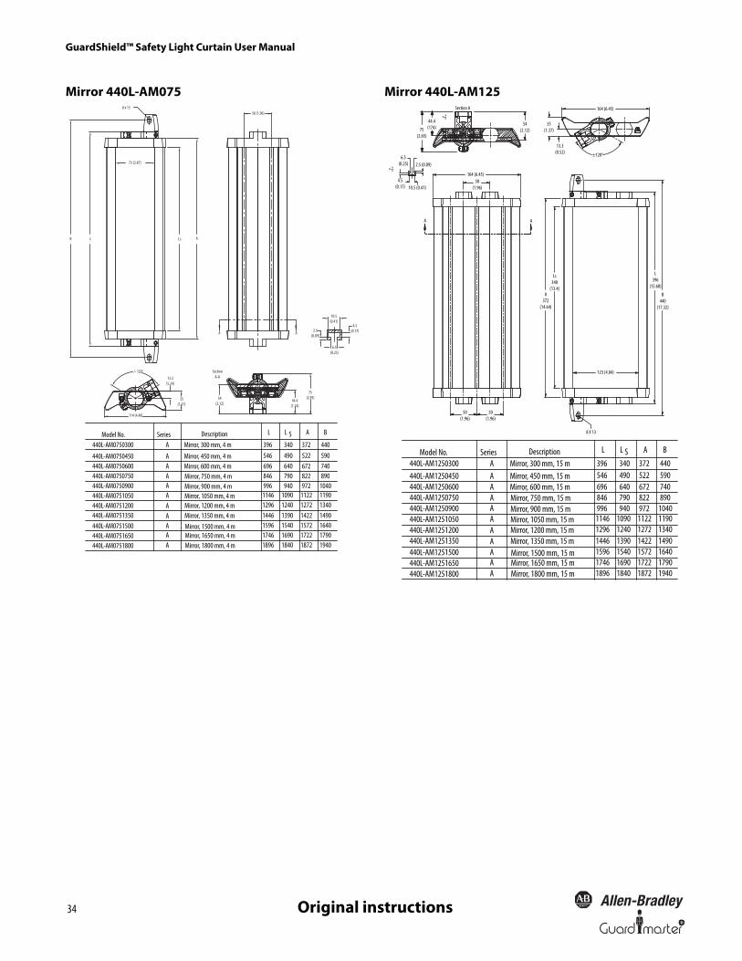
GuardShield™ Safety Light Curtain User Manual
34 R
Original instructions
Mirror 440L-AM075 Mirror 440L-AM1258 x 13
50 (1.96)
73 (2.87)
ALsLB
A A
SectionA-A
+/- 120°
114 (4.48)
13.3(5.24)
35(1.37)
54(2.12)
44.4(1.74)
75(2.95)
2.5(0.09)
6.5(0.25)
4.5(0.17)
10.5(0.41)
AAAA
Description
Mirror, 600 mm, 4 m
AA
A
Mirror, 450 mm, 4 m
Mirror, 300 mm, 4 m
Mirror, 750 mm, 4 mMirror, 900 mm, 4 mMirror, 1050 mm, 4 mMirror, 1200 mm, 4 mMirror, 1350 mm, 4 mMirror, 1500 mm, 4 m
Mirror, 1800 mm, 4 mMirror, 1650 mm, 4 m
AAA
AModel No. L L A BS
440L-AM0750300
440L-AM0750450440L-AM0750600440L-AM0750750440L-AM0750900440L-AM0751050440L-AM0751200440L-AM0751350440L-AM0751500440L-AM0751650440L-AM0751800
396 340 372 440546 490 522 590696 640 672 740846 790 822 890996 940 972 10401146 1090 1122 11901296 1240 1272 13401446 1390 1422 14901596 1540 1572 16401746 1690 1722 17901896 1840 1872 1940
Series
"Z"
A A
±120°
8 X 13
"Z"
164 (6.45)
35(1.37)
13.3(0.52)
54(2.12)
Section A
44.4(174)75
(2.65)
10.5 (0.41)
2.5 (0.09)6.5
(0.25)
4.5(0.17)
164 (6.45)50
(1.96)
50(1.96)
50(1.96)
B440
(17.32)
L396
(15.60)
Ls340
(13.4)A
372(14.64)
123 (4.84)
AAAA
Description
Mirror, 600 mm, 15 m
AA
A
Mirror, 450 mm, 15 mMirror, 300 mm, 15 m
Mirror, 750 mm, 15 mMirror, 900 mm, 15 mMirror, 1050 mm, 15 mMirror, 1200 mm, 15 mMirror, 1350 mm, 15 mMirror, 1500 mm, 15 m
Mirror, 1800 mm, 15 mMirror, 1650 mm, 15 m
AAAA
Model No. L L A BS440L-AM1250300440L-AM1250450440L-AM1250600440L-AM1250750440L-AM1250900440L-AM1251050440L-AM1251200440L-AM1251350440L-AM1251500440L-AM1251650440L-AM1251800
396 340 372 440546 490 522 590696 640 672 740846 790 822 890996 940 972 10401146 1090 1122 11901296 1240 1272 13401446 1390 1422 14901596 1540 1572 16401746 1690 1722 17901896 1840 1872 1940
Series

GuardShield™ Safety Light Curtain User Manual
35R
Original instructions
Corner Mirror for Multi-Sided GuardingSpecially constructed glass mirrors for 2- and 3-sided safeguarding applications.
Note: Each mirror reduces maximum scan range by 10% per mirror. Each corner mirror suppled with two end-cap mounting brackets.
� = J or K; � = D or R; � = A or D
Mounting Stand—440L-AMSTD Laser Alignment Tool
GuardShield Light Curtain Cat. No. Narrow Mirror Short-Range 0…4 m Cat. No. Wide Mirror Long-Range 4…15 m Cat. No.
440L-P4�0160Y�440L-P2K�0160YD 440L-AM0750300 440L-AM1250300
440L-P4�0320Y�440L-P2K�0320YD 440L-AM0750450 440L-AM1250450
440L-P4�0480Y�440L-P2K�0480YD
440L-P4A2500YD440L-AM0750600 440L-AM1250600
440L-P4�0640Y�440L-P2K�0640YD 440L-AM0750750 440L-AM1250750
440L-P4�0800Y�440L-P2K�0800YD 440L-AM0750900 440L-AM1250900
440L-P4�0960Y�440L-P2K�0960YD
440L-P4A3400YD440L-AM0751050 440L-AM1251050
440L-P4�1120Y�440L-P2K�1120YD 440L-AM0751200 440L-AM1251200
440L-P4�1280Y�440L-P2K�1280YD 440L-AM0751350 440L-AM1251350
440L-P4�1440Y�440L-P2K�1440YD 440L-AM0751500 440L-AM1251500
440L-P4�1600Y�440L-P2K�1600YD 440L-AM0751650 440L-AM1251650
440L-P4�1760Y�440L-P2K�1760YD 440L-AM0751800 440L-AM1251800
66.8(2.63)
19.05(0.75)
62.48(2.46)
12.19(0.48)
4.0(0.15)
17.78(0.70)
35.56(1.4)
44.45(1.75)
4.29 (0.169) hole dia.81° x 2.66 (0.105)
Countersink
1828.8(72)
63.5 (2.5)25.4(1.0)
12.7 (0.5) Dia. 4X
6.35(0.25)
6.35(0.25)
76.2(3.0)
19.05 (0.75)
11.1 (7/16) Dia.
25.4(1.0)
76.2(3.0)63.5
(2.5)
304.8(12)
M10 x 1.5 mmClass 6g thru 4 pl
381.0 (15)
GuardShield LAT Bracket—440L-AF6109
Laser Alignment Tool (LAT)—440L-ALAT
Pedestal floor stand
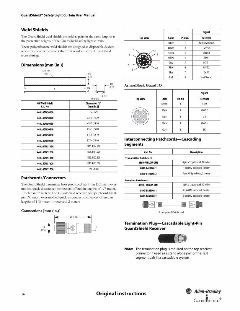
GuardShield™ Safety Light Curtain User Manual
36 R
Original instructions
Weld ShieldsThe GuardShield weld shields are sold as pairs in the same lengths as
the protective heights of the GuardShield safety light curtain.
These polycarbonate weld shields are designed as disposable devices
whose purpose is to protect the front window of the GuardShield
from damage.
Dimensions [mm (in.)]
Patchcords/ConnectorsThe GuardShield transmitter host patchcord has 4-pin DC micro over-
molded quick-disconnect connectors offered in lengths of 1/3 meter,
1 meter and 2 meters. The GuardShield receiver host patchcord has 8-
pin DC micro over-molded quick-disconnect connectors offered in
lengths of 1/3 meter, 1 meter and 2 meters.
Connections [mm (in.)]
ArmorBlock Guard IO
Interconnecting Patchcords—Cascading Segments
Termination Plug—Cascadable Eight-Pin GuardShield Receiver
Note: The termination plug is required on the top receiver connector if used as a stand alone pair or the last segment pair in a cascadable system
GS Weld ShieldCat. No.
Dimension “L”[mm (in.)]
440L-AGWS0160 175.3 (6.9)
440L-AGWS0320 335.3 (13.20)
440L-AGWS0480 495.3 (19.50)
440L-AGWS0640 655.3 (25.80)
440L-AGWS0800 815.3 (32.10)
440L-AGWS0960 975.4 (38.40)
440L-AGWS1120 1135.4 (44.70)
440L-AGWS1280 1295.4 (51.00)
440L-AGWS1440 1455.4 (57.30)
440L-AGWS1600 1615.4 (63.60)
440L-AGWS1760 1778 (70.00)
49.5 (1.95)
L
37.3 (1.47)
R24 2X
10.16 (0.4)
3.0 (0.118)Thick
R12 2X
47 (1.85)
14(0.56)
Top View Color Pin No.
Signal
Receiver
White 1 Auxiliary Output
Brown 2 +24V DC
Green 3 Ground
Yellow 4 EDM
Gray 5 OSSD 1
Pink 6 OSSD 2
Blue 7 0V DC
Red 8 Start/Restart
Top View Color Pin No
Signal
Receiver
Brown 1 + 24V
White 2 OSSD 2
Blue 3 0 V
Black 4 OSSD 1
Gray 5 NC
Cat. No. Description
Transmitter Patchcord
889D-F4HLDM-0M3 4 pin M12 patchcord, 12 inches
889D-F4HLDM-1 4 pin M12 patchcord, 1 meter
889D-F4HLDM-2 4 pin M12 patchcord, 2 meters
Receiver Patchcord
889D-F8ABDM-0M3 8 pin M12 patchcord, 12 inches
889D-F8ABDM-1 8 pin M12 patchcord, 1 meter
889D-F8ABDM-2 8 pin M12 patchcord, 1 meter
567
8
4
31
2
Example of Patchcord
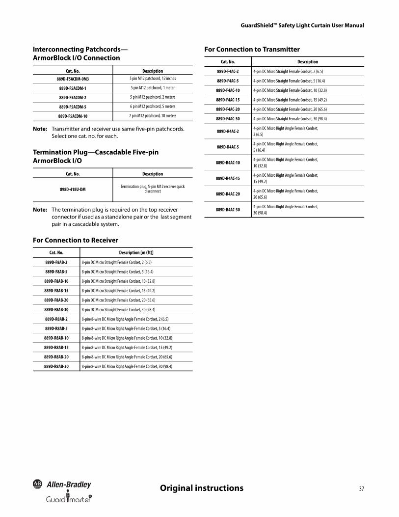
R
GuardShield™ Safety Light Curtain User Manual
37Original instructions
Interconnecting Patchcords—ArmorBlock I/O Connection
Note: Transmitter and receiver use same five-pin patchcords. Select one cat. no. for each.
Termination Plug—Cascadable Five-pin ArmorBlock I/O
Note: The termination plug is required on the top receiver connector if used as a standalone pair or the last segment pair in a cascadable system.
For Connection to Receiver
For Connection to Transmitter
Cat. No. Description889D-F5ACDM-0M3 5 pin M12 patchcord, 12 inches
889D-F5ACDM-1 5 pin M12 patchcord, 1 meter
889D-F5ACDM-2 5 pin M12 patchcord, 2 meters
889D-F5ACDM-5 6 pin M12 patchcord, 5 meters
889D-F5ACDM-10 7 pin M12 patchcord, 10 meters
Cat. No. Description
898D-418U-DM Termination plug, 5-pin M12 receiver quick disconnect
Cat. No. Description [m (ft)]
889D-F8AB-2 8-pin DC Micro Straight Female Cordset, 2 (6.5)
889D-F8AB-5 8-pin DC Micro Straight Female Cordset, 5 (16.4)
889D-F8AB-10 8-pin DC Micro Straight Female Cordset, 10 (32.8)
889D-F8AB-15 8-pin DC Micro Straight Female Cordset, 15 (49.2)
889D-F8AB-20 8-pin DC Micro Straight Female Cordset, 20 (65.6)
889D-F8AB-30 8-pin DC Micro Straight Female Cordset, 30 (98.4)
889D-R8AB-2 8-pin/8-wire DC Micro Right Angle Female Cordset, 2 (6.5)
889D-R8AB-5 8-pin/8-wire DC Micro Right Angle Female Cordset, 5 (16.4)
889D-R8AB-10 8-pin/8-wire DC Micro Right Angle Female Cordset, 10 (32.8)
889D-R8AB-15 8-pin/8-wire DC Micro Right Angle Female Cordset, 15 (49.2)
889D-R8AB-20 8-pin/8-wire DC Micro Right Angle Female Cordset, 20 (65.6)
889D-R8AB-30 8-pin/8-wire DC Micro Right Angle Female Cordset, 30 (98.4)
Cat. No. Description
889D-F4AC-2 4-pin DC Micro Straight Female Cordset, 2 (6.5)
889D-F4AC-5 4-pin DC Micro Straight Female Cordset, 5 (16.4)
889D-F4AC-10 4-pin DC Micro Straight Female Cordset, 10 (32.8)
889D-F4AC-15 4-pin DC Micro Straight Female Cordset, 15 (49.2)
889D-F4AC-20 4-pin DC Micro Straight Female Cordset, 20 (65.6)
889D-F4AC-30 4-pin DC Micro Straight Female Cordset, 30 (98.4)
889D-R4AC-24-pin DC Micro Right Angle Female Cordset, 2 (6.5)
889D-R4AC-54-pin DC Micro Right Angle Female Cordset, 5 (16.4)
889D-R4AC-104-pin DC Micro Right Angle Female Cordset, 10 (32.8)
889D-R4AC-154-pin DC Micro Right Angle Female Cordset, 15 (49.2)
889D-R4AC-204-pin DC Micro Right Angle Female Cordset, 20 (65.6)
889D-R4AC-304-pin DC Micro Right Angle Female Cordset, 30 (98.4)
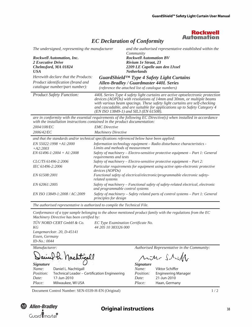
GuardShield™ Safety Light Curtain User Manual
38R
Original instructions
1 / 2Document Control Number: SEN-0339-H-EN (Original)
EC Declaration of Conformityand the authorised representative established within theCommunityRockwell Automation BVRivium 1e Straat, 232209 LE Capelle aan den IJsselNetherlands
GuardShield™ Type 4 Safety Light Curtains Allen-Bradley / Guardmaster 440L Series (reference the attached list of catalogue numbers)
Product Safety Function: 440L Series Type 4 safety light curtains are active optoelectronic protectiondevices (AOPDs) with resolutions of 14mm and 30mm, or multiple beamswith various beam spacings. These safety light curtains are self-checkingand cascadable, and are suitable for applications up to Safety Category 4(EN ISO 13849-1) and SIL3 (EN 61508).
are in conformity with the essential requirements of the following EC Directive(s) when installed in accordance with the installation instructions contained in the product documentation:
evitceriDCMECE/801/4002evitceriDyrenihcaMCE/24/6002
and that the standards and/or technical specifications referenced below have been applied:EN 55022:1998 +A1:2000+A2:2003
Information technology equipment – Radio disturbance characteristics - Limits and methods of measurementSafety of machinery – Electro-sensitive protective equipment – Part 1: Generalrequirements and tests
CLC/TS 61496-2:2006 IEC 61496-2:2006
Safety of machinery – Electro-sensitive protective equipment – Part 2:Particular requirements for equipment using active opto-electronic protectivedevices (AOPDs)Functional safety of electrical/electronic/programmable electronic safety-related systemsSafety of machinery – Functional safety of safety-related electrical, electronicand programmable control systemsSafety of machinery – Safety related parts of control systems – Part 1: Generalprinciples for design
Conformance of a type sample belonging to the above mentioned product family with the regulations from the EC Machinery Directive has been certified by: TÜV NORD CERT GmbH & Co. KG Langemarckstr. 20, D-45141 Essen, GermanyID-No.: 0044
EC Type Examination Certificate No. 44 205 10 383326 000
Manufacturer: Authorised Representative in the Community:
Signature Signature Name: Daniel L. Nachtigall Name: Viktor Schiffer Position: Technical Leader – Certification Engineering Position: Engineering Manager Date:Place:
17-Jun-2010 Date:Place:
21-Jun-2010
The undersigned, representing the manufacturer
Rockwell Automation, Inc.2 Executive DriveChelmsford, MA 01824USAHerewith declare that the Products:Product identification (brand andcatalogue number/part number):
EN 61496-1:2004 + A1:2008
EN 61508:2001
EN 62061:2005
EN ISO 13849-1:2008 / AC:2009
The authorised representative is authorized to compile the Technical File.
Milwaukee, WI USA Haan, Germany
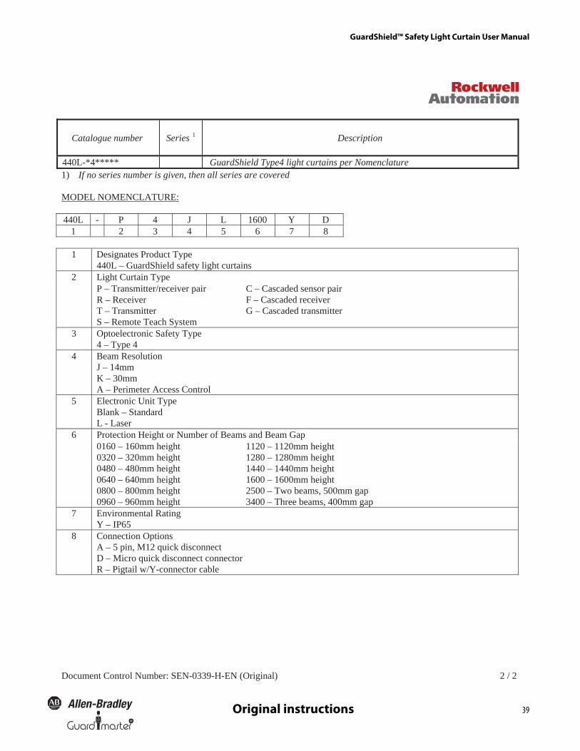
GuardShield™ Safety Light Curtain User Manual
39R
Original instructions
2 / 2 N (Original)E-H-9330-NES :rebmuN lortnoC tnemucoD
Catalogue number Series 1 Description
440L-*4***** GuardShield Type4 light curtains per Nomenclature 1) If no series number is given, then all series are covered
MODEL NOMENCLATURE: 440L - P 4 J L 1600 Y D
1 2 3 4 5 6 7 8
1 Designates Product Type 440L – GuardShield safety light curtains Light Curtain Type 2 P – Transmitter/receiver pair R – Receiver T – Transmitter S – Remote Teach System
C – Cascaded sensor pair F – Cascaded receiver G – Cascaded transmitter
3 Optoelectronic Safety Type 4 – Type 4
4 Beam Resolution J – 14mm K – 30mm A – Perimeter Access Control
5 Electronic Unit Type Blank – Standard L - Laser Protection Height or Number of Beams and Beam Gap 6 0160 – 160mm height 0320 – 320mm height 0480 – 480mm height 0640 – 640mm height 0800 – 800mm height 0960 – 960mm height
1120 – 1120mm height 1280 – 1280mm height 1440 – 1440mm height 1600 – 1600mm height 2500 – Two beams, 500mm gap 3400 – Three beams, 400mm gap
7 Environmental Rating Y – IP65
8 Connection Options A – 5 pin, M12 quick disconnect D – Micro quick disconnect connector R – Pigtail w/Y-connector cable

GuardShield™ Safety Light Curtain User Manual
40 R
Original instructions

GuardShield™ Safety Light Curtain User Manual
40 R
Original instructions

www.rockwellautomation.com
Power, Control and Information Solutions HeadquartersAmericas: Rockwell Automation, 1201 South Second Street, Milwaukee, WI 53204 USA, Tel: (1) 414.382.2000, Fax: (1) 414.382.4444Europe/Middle East/Africa: Rockwell Automation, Vorstlaan/Boulevard du Souverain 36, 1170 Brussels, Belgium, Tel: (32) 2 663 0600, Fax (32) 2 663 0640Asia Pacific: Rockwell Automation, Level 14, Core F, Cyberport 3, 100 Cyberport Road, Hong Kong, Tel: (852) 2887 4788, Fax: (852) 2508 1846
Publication PN-7391710000085454 Ver 01 Copyright ©2012 Rockwell Automation, Inc. All Rights Reserved. Printed in USA.August 2012
GuardShield is a trademark of Rockwell Automation, Inc.