gthandbook-final-edits-new library/research/coal/energy systems... · lean oxidation of methane on...
TRANSCRIPT

255255
3.2.2-1 IntroductionThe earliest work on what is now termed catalytic combustion was conducted
by Pfefferle at Engelhard Corporation in the 1970s and introduced the use of both catalytic and non-catalytic combustion reactions in a temperature range amenable to both1. The original-type catalytic combustor is a ceramic honeycomb monolith containing catalytically-coated parallel channels and placed within a combustion chamber2. In this original-type catalytic combustor, surface reactions release heat and reactive intermediates into the boundary layer above the surface, eventually inducing gas-phase (non-catalytic) reactions. As a consequence, combustor operation can be at lean limits well beyond those feasible without the infl uence of a catalyst, and pollutant emissions can be extremely low. Early work on systems of this type were conducted at Engelhard, Acurex, Westinghouse, NASA, the Air Force, and elsewhere3.
Active interest in catalytic combustion for power generation increased during the early 1990s as it became clear that continued pressure for reduced emissions could not be met simply by re-design of conventional combustors. A new approach of partial conversion in the catalyst bed and the use of metal catalyst substrates to circumvent thermal shock issues, revived catalytic combustion for power generation. Metal-substrate type catalyst beds were thus employed for catalytic combustion with increasing success during the 1990s, demonstrating the low NOx potential of catalytic combustion for gas turbine applications4. Ultimately, two very different systems emerged during this period: a fuel-lean catalyst system developed by Catalytica, Inc. and a fuel-rich catalyst system developed by Precision Combustion, Inc5. Engine tests of these two systems are described, respectively, in Yee et al. and Smith et al.6 . These systems are also described in greater detail in Sections 3.2.2.1.1 and 3.2.2.1.2 of this Handbook.
3.2.2-2 Role of Catalysis in Combustion
In broad terms, a catalyst is used to promote a desired chemical reaction. Catalysts fi nd a wide range of applications in the production of energy and power, but for combustion turbines there are three basic classes of reactions that one may desire to promote: fuel preparation such as reforming prior to combustion, fuel oxidation with heat release, and pollutant destruction. “Catalytic combustion” normally refers to fuel oxidation with heat release, particularly when the catalyst is placed inside an engine and within the combustor casing. We restrict our discussion here to catalytic combustion and exclude other catalytic processes such as fuel reforming or exhaust-gas cleanup. In simple terms, the presence of a combustion catalyst enables complete combustion at lower temperatures than otherwise possible. This fact can be used for multiple benefi ts, but the primary motivation for low temperature combustion is reduced NOx emissions and/or increased combustor turndown. In particular, most non-catalytic combustors operate with peak fl ame temperatures higher than 1525°C (2780°F) to ensure adequate fl ame stability and margin from blowout. As is well known, NOx emissions even for perfectly premixed fuel-air fl ames at 1525°C (2780° F) can exceed the 3 ppm threshold (at 15% O2) targeted for many new power plants7. Catalytic combustors, however, can operate stably with fl ame temperatures far below 1525°C (2780°F), offering both reduced NOx emissions and improved combustor turndown.
3.2.2-3 Catalyst Materials for Combustion Applications
By defi nition a catalyst promotes a chemical reaction, such as fuel with oxygen, but is itself neither consumed nor produced by the reaction. Precious metal catalysts are useful in promoting combustion reactions, and it is desirable to preserve such valuable catalysts by fi xing them to a stationary, solid surface known as a substrate. The reactants, fuel and air, react on contact with the catalyst surface
Catalytic Combustion3.2.2
Gas Turbine Group, Precision Combustion, Inc.410 Sackett Point Road, CT 06473
phone: (203) 287-3700 x217email: [email protected]
Dr. Lance Smith
Dr. Hasan Karim
Dr. Shahrokh Etemad
Dr. William C. Pfefferle

256
forming combustion products. For solid fuels such as coal, this means that liquefaction or gasification of the fuel is required to enable contact with the solid catalyst surface in the presence of air. Regardless of fuel type, the need for the reactants to contact a solid catalyst surface also means that a high substrate surface area is desirable, as is a high rate of mass transfer to the solid surface. Thus, catalyst substrates typically take the form of small pellets, rods, wires, tubes, honeycombs, foams, or other high-surface-area shapes through which flow can pass. Channel diameters through such structures are typically between 1 mm and 1 cm in diameter, depending on size and pressure drop requirements. Substrates can be made of metal or ceramic materials, but must withstand the expected operating environment in a gas turbine engine, particularly with regard to thermal gradients and thermal shock8. Metal substrates best fill this need, but their temperature must be limited to less than 950°C (1750°F) to ensure sufficient material strength and long life. Ceramic materials can operate at higher temperatures, but issues of thermal shock failure during the transient operating conditions required for gas turbine operation have not been fully resolved. Thus, despite their inherent temperature limitations, metal substrates have been nearly universally adopted for gas turbine catalytic combustion, even for machines with firing temperatures hundreds of degrees higher than 950°C (1750°F). As a result, a prominent feature of successful catalytic combustor designs has been control or limitation of catalyst temperature without sacrifice in engine, combustor, or emissions performance. Once the reactants are in contact with the substrate surface, it is also desirable that catalytic reactions proceed quickly. This requires a large number of active catalyst surface sites per unit surface area of substrate. For this purpose a high-surface-area “support” material such as a porous ceramic washcoat may be applied to the substrate, creating a new “rough” or porous surface that can have thousands of times the surface area of the raw substrate. The catalyst is finely dispersed across this rough surface and throughout its pores, to give a high density of active sites for chemical reaction. Specific procedures for preparing such supported catalysts have been disclosed in the literature9. Figure 1 presents a cross-sectional view of an actual washcoat support, containing precious-metal catalyst, and bonded to an underlying metal substrate. A high density of active surface sites is especially important in achieving the lowest possible lightoff temperature for a given catalyst. For practical applications of catalytic combustion, lightoff temperature is a critical parameter that determines both system operation and system design. The lightoff process can be depicted graphically as suggested by Pfefferle and Pfefferle and as shown schematically here in figure 210. Prior to catalyst lightoff the temperature difference between the catalyst surface and the reactant gas stream is small (tens of degrees or less) and the reaction rate is slow enough that this temperature difference is sufficient to remove all heat released at the surface. Pre-lightoff operating conditions correspond to region I in figure 2. However, if gas and catalyst temperatures are increased, reaction rates will increase exponentially with temperature until reactants are consumed as quickly as they arrive at the surface. When this occurs, the surface reaction is said to be mass transfer limited, since mass transfer of fuel and oxygen to the surface now limit the overall reaction rate and temperature has little impact. At this condition the catalyst temperature will greatly exceed (by hundreds of degrees) the temperature of the reactant gas stream, and in fact, the catalyst will operate close to the adiabatic flame temperature of the reactant gas stream if no external cooling is provided. This changeover to mass transfer limited operation at greatly increased catalyst temperature is known as catalyst lightoff, and occurs rapidly (on the order of seconds) once the lightoff temperature is reached. Figure 2 indicates how lightoff temperature is defined and why lightoff is rapid. The solid curve represents heat release rate (in Watts, for example) from exothermic reactions at the catalyst surface, as a function of catalyst temperature. The dashed curve indicates the effect of catalyst temperature on the rate of heat removal from the catalyst surface,
Fig. 2. Representation of heat generation and heat removal as a function of catalyst temperature, as during catalyst lightoff
Temperature (K)
HeatRate(W)
I
II
III
Ql.o.
Tl.o.
heat release
heat removal
Tgas
Fig. 1. Microscope photograph of sectioned catalyst support and substrate. The catalyst support is a ceramic washcoat, bonded to the underlying metal substrate. The scale of this photograph is roughly 100 µm (0.004 in) in total height.
100 µm(0.004 in)
substrate (solid)
reactants (gas)
catalyst / support

257
predominantly by convection to the reactant stream. The dashed curve’s point of intersection on the x-axis is the gas stream temperature. Note that the solid curve is independent of gas stream temperature, but the dashed curve will slide left and right, depending on gas stream temperature, with a constant slope determined by the convective heat transfer coefficient. For steady-state operation heat removal must equal heat release, so operation must be at an intersection point of the solid and dashed curves. Furthermore, for this intersection point to be a stable operating condition, an increase in catalyst temperature must lead to greater heat removal than heat release. At lightoff, this stability condition fails, and lightoff temperature Tl.o. is defined at the point of tangency between the solid and dashed curves, as shown. At this point, any increase in catalyst temperature leads to greater heat release than heat removal, with the result that catalyst temperature rapidly increases until reaction rate is limited by mass transfer of reactants to the catalyst surface. Thus, catalyst temperature passes through the unstable region II, and stabilizes at its mass-transfer-limited value in region III where the dashed curve and the solid curves again intersect. Catalyst lightoff is therefore a rapid transient event, and can be measured for any catalyst material with only weak dependence on heat transfer coefficient. Note that some authors define lightoff temperature in terms of the gas temperature Tgas during lightoff, instead of catalyst temperature Tl.o. at lightoff as defined here. Catalyst materials for combustion applications have been carefully evaluated by a number of researchers11. Methane and natural gas fuels have been the recent focus of interest because natural gas is currently the low-emissions fuel of choice for power-generating gas turbines. Johansson and co-workers have reviewed the catalytic combustion literature and summarized lightoff temperatures for fuel-lean oxidation of methane on various catalysts, as listed in table 112. Dalla Betta (1997) reviewed and summarized fuel-lean methane reaction rates at 400°C (750°F) for a range of catalyst materials tested, and the more active of these are also listed in table 113. In both reviews, palladium (Pd) catalysts show the greatest activity for methane oxidation, and in general the consensus in the literature has been that, for fuel-lean combustion of methane, Pd-based catalysts are the only practical choice because only they offer acceptable activity, lightoff temperature, and resistance to volatilization. However, the adoption of Pd-based catalysts has come with difficulties resulting from the complex morphology and behavior of the Pd-PdO system and its reactions with methane, including deactivation at high temperature (above about 750°C (1380°F)), hysteresis in reaction rate over heating and cooling cycles, and oscillations in activity and temperature14. In addition, lightoff and extinction temperatures are well above 300°C (570°F) for fuel-lean reaction of methane on Pd-based catalysts, thus requiring the use of a preburner in many engine applications15. A wider choice of catalysts is possible for fuel-rich reaction of methane, and the complex behaviors of fuel-lean methane reaction on Pd are avoided. For example, Lyubovsky et al. compared fuel-lean and fuel-rich activity for three precious metal catalysts in an isothermal reactor, and demonstrated that all three could be practically used for fuel-rich catalytic reactors16. A comparison of measured catalyst activity for Pd, Pt, and Rh catalysts, under both fuel-rich and fuel-lean conditions, is shown here in figure 3 as a function of catalyst temperature17. Note that figure 3 does not depict thermal lightoff in the same sense as figure 2, since the data in figure 3 were obtained at isothermal conditions (heat transfer was essentially infinite, so the catalyst could not self heat). The first observation to make in figure 3 is that, for all three catalysts, methane conversion (a measure of catalyst activity) is generally much higher under fuel-rich conditions than under fuel-lean conditions. Furthermore, under fuel-lean conditions, only the Pd catalyst shows sustained measurable activity below 600°C (1110°F), whereas all three catalysts are always active in this range under fuel-rich conditions. Evidently the oxidizing environment of fuel-lean mixtures leads to oxidation of the catalyst and this has a pronounced effect on catalyst activity. Oxidation also leads to greater volatilization of Pt catalyst, limiting the usable life of Pt-based catalysts even at temperatures far below 950°C (1750°F). For fuel-rich combustion of methane, however, Pd, Pt, or Rh-based catalysts may be used without suffering from oxidation.
Dr. Lance Smith, Dr. Hasan Karim, Dr. Shahrokh Etemad, Dr. William C. Pfefferle
Table 1 Lightoff temperature and reaction rate for methane oxidation under fuel-lean conditions, for various catalyst materials
Source: see note 4 (Dalla Betta) and note 8 (Johansson).
Catalyst TypeSpecific Examplesof Catalyst Type
1Lightoff Temperature(C)
2Reaction Rate(10-7 mol / g-s)
Platinum Group MetalsPd / Al2O3 340 – 460 300Pt / Al2O3 590 – 710 50
Perovskite 390 – 690La0.5Sr0.5CoO3 7LaCoO3 1
Hexa-aluminate 500 – 700Sr0.8La0.2MnAl11O19 3
Zeolite 600 - 750

258
For syngas and high-hydrogen fuels, catalyst lightoff of CO and H2 is of interest for both fuel-lean and fuel-rich conditions. Recent work at Precision Combustion, Inc., sponsored by the U.S. Department of Energy, has shown a precious-metal catalyst lightoff temperature of 180°C (350°F) for fuel-rich reaction of syngas. This value has been measured for a syngas mixture composed of 25% H2 and 35% CO (remainder diluent), but the lightoff temperature is relatively insensitive to syngas composition unless CO levels drop to very low values, thus leaving essentially a high-hydrogen fuel having significantly lower lightoff temperature. Light-off temperatures for fuel-lean syngas mixtures were also measured below 180°C (350°F). In all cases, the 180°C (350°F) or lower lightoff temperature is well below the compressor discharge temperatures of industrial and large-frame turbines, and the need for a preburner is thereby avoided.
Flame Temperature Considerations
Actual flame temperatures for catalytic combustion will vary depending on the design approach used to integrate the catalytic reaction zone with the gas-phase combustion zone and also on the turbine inlet temperature requirement for the application engine. In any case, flame temperatures greater than about 1100°C (2000°F) are required for gas-phase reactions to complete the burnout of hydrocarbon fuels and CO in a reasonable residence time (on the order of 10 ms). Thus, systems which rely on catalyst-induced autoignition to stabilize combustion will normally have a minimum gas-phase combustion zone temperature of about 1100°C (2000° F), although the catalyst itself may be limited to temperatures well below this value. Systems which use conventional flameholding techniques without catalyst-induced autoignition (but with catalyst augmentation of flame stability) normally require higher flame temperatures to prevent blowout, with typical minimum flame temperatures exceeding 1300°C (2400°F) for hydrocarbon fuels. In most power generation applications, it is required that the turbine operates over a range of loads while meeting emissions regulations. The combustor must therefore be designed to operate with flame temperatures above the minimum achievable value at base load (full power) so that the machine can be turned down to a flame temperature near the minimum achievable value at the lowest required low-emissions load point. Thus, actual flame temperatures at base load are generally higher than the minimums listed in the previous paragraph. In addition, for modern high-efficiency engines having high turbine inlet temperatures, actual flame temperatures at base load may need to be higher than the minimums listed above simply to meet the required turbine rotor inlet temperature after the addition of necessary cooling air. For example, General Electric’s 7FA engine has a published turbine rotor inlet temperature of 1325°C (2420°F) (Eldrid et al., 2001) and a published temperature drop due to cooling air addition at the first stage nozzle (stator) of 140°C (280°F), giving a minimum flame temperature of 1480°C (2700°F) prior to the first-stage nozzle18. The above considerations establish the minimum required flame temperature at base load, but for ultra-low NOx operation a maximum flame temperature is also present, based on increasing formation of thermal NOx with increasing temperature19. It is generally accepted that at temperatures above about 1525°C (2780°F) NOx emissions increase markedly with temperature, and generally exceed 3 ppm (at 15% O2) for premixed flames of hydrocarbon fuels in air. Thus, for a given low-emissions application the design choice for base load flame temperature falls within a window that is generally less than 1525°C (2780°F) but higher than the minimum required. Based on such flame temperature considerations, catalytic combustion systems for gas turbines can be classified in three basic categories as shown in table 2. The categories are most directly stated in terms of turbine rotor inlet temperature requirements. For the first two categories in table 2 (low-temperature and high-temperature turbines), turbine rotor inlet temperatures are sufficiently below the 1525°C (2780°F) thermal NOx limit that catalytic combustion can be used to provide stable operation, thus providing ultra-low NOx emissions even at base load. For the third category (ultra-high temperature turbines); however, flame temperatures in excess of 1525°C (2780°F) may be required simply to meet the required turbine rotor inlet temperature after the addition of necessary cooling air. Therefore, NOx emissions for such applications may be higher than 3 ppm unless cooling air requirements are reduced (as in the steam-cooled H-engine for example), or unless alternative developments are advanced to allow low-NOx operation at higher flame temperatures (as discussed further below).
3.2.2 Catalytic Combustion
Fig. 3. Catalyst activity for methane oxidation under fuel-rich and fuel-lean conditions. Filled symbols represent increasing temperature, and closed symbols represent decreasing temperature (the selected temperature ramp was externally controlled by electric heaters).

259
Note that in all cases, catalytic combustion provides additional benefits other than low emissions. In particular, catalytic combustion can be used to provide extended turndown by allowing stable combustion at low part-load flame temperatures and can also be used to reduce combustion dynamics (combustion-induced pressure oscillations) by shifting fuel energy release to the catalyst surface and away from the gas-phase combustion zone. Reduced combustion dynamics may be an especially important benefit in high-firing-temperature machines that are susceptible to combustion dynamics as a result of their inherent high rate of fuel energy release.
Table 2 Categories for gas turbine applications of catalytic combustion, based on turbine rotor inlet temperature. The term 1-Stage means a single stage system combining both catalyst and gas-phase reactions. The term 2-Stage means that combustion occurs in two stages, sequential and separate, where the first stage is catalytic and the second is gas-phase. (See Figure 4 for schematic examples of 1-Stage and 2-Stage systems.)
Specific considerations for each of the categories in table 2 are discussed in the following subsections, especially as related to catalytic combustion system design for each category.
Catalytic Combustion at Low Flame Temperatures (Uncooled Turbines)
For uncooled turbines such as microturbines, turbine inlet temperatures are generally within catalyst material temperature limits (less than 1000°C (1830°F). This means that the catalyst and substrate can tolerate the maximum required flame temperature, and if complete combustion can be sustained, there is no need to separate the gas-phase combustion zone from the catalyst. Thus, a simple catalytic combustor for this application can comprise only a premixer and a catalyst bed, as shown schematically in the right-hand panel of figure 4. This simple system is considered a single-stage system, although fuel is oxidized within this single stage by both catalytic reactions on the catalyst surface and gas-phase reactions in the fluid stream above the surface. Because these reactions can go to completion (all fuel converted to products) within the catalyst stage, this single-stage system is also known as a “total conversion” catalytic reactor.
Air
Premixer Catalytic Reactor
Homogenous Reaction
Fuel
Premixer
Air
Fuel
Catalytic Reactor
Partial Conversion Total Conversion Fig. 4. Schematic examples of 2-Stage (partial conversion catalyst) and 1-Stage (total conversion catalyst) catalytic combustors, in left and right panels, respectively
Dr. Lance Smith, Dr. Hasan Karim, Dr. Shahrokh Etemad, Dr. William C. Pfefferle
Low-Temperature(Uncooled) Turbines
High-Temperature (Cooled) Turbines
Ultra-High Temperature(> F-Class) Turbines
EngineApplications Microturbines Industrial
D-, E-, F-ClassFB-Class G-Class
Approachesto CatalyticCombustion
1-Stage or 2-Stage 2-Stage 2-Stage 1- or 2-StageCeramic
Low Oxygen 2-Stage (EGR)
Benefits:
1. Emissions
2. Turndown
3. Dynamics
√
√
√
√
√
√
?
√
√
√
√
√
√
√
√
BarrierIssues - - - Materials
Develop.Cycle & MachineDevelop.

260
Note that the single-stage “total conversion” catalytic reactor requires gas-phase reactions to complete the oxidation of all fuel in a reasonable length or residence time. Complete combustion (e.g. 99.9% combustion efficiency) without gas-phase reactions would require mass transfer of nearly all fuel (e.g. 99.9%) to the catalyst surface for reaction, which would require an impractically sized catalyst in terms of length, cross-sectional area, and/or channel size. Thus, the single-stage “total conversion” catalytic reactor must provide sufficient catalytic reaction and concomitant heating of the fuel/air mixture that gas-phase autoignition is induced throughout, providing combustion completion even if the fuel/air mixture is outside its flammability limits. Based on the adiabatic flame temperature of the fuel/air mixture passing over the catalyst, this autoignition requirement determines the minimum required catalytic conversion of fuel. Or, in the opposite sense, based on the practically achievable catalytic conversion of fuel, the autoignition requirement determines the minimum adiabatic flame temperature of the fuel/air mixture. A separate consideration is, as stated earlier, the adiabatic flame temperature of the fuel/air mixture must generally exceed at least 1100°C (2000°F) to provide complete burnout in a reasonable residence time. At 1100°C (2000°F) metal substrates cannot be used to support the catalyst, and a ceramic substrate must be used. Thus, the single-stage catalytic combustor is generally ceramics-based, and is prone to ceramics-related issues such as thermal stress and thermal shock. Early catalytic combustors of the type originally developed at Engelhard were single-stage ceramics-based systems20. Currently, however, metal substrates have gained favor in many catalyst applications, including catalytic combustion. Metals are especially suitable for gas turbine applications since they are able to withstand gas turbine demands such as thermal stress and thermal shock. But metal temperatures must normally be limited to less than about 950°C (1750°F) for long-term durability, and this precludes the use of the single-stage “total conversion” system described above. Instead, a two-stage “partial conversion” system must be used where only a portion of the fuel is reacted in the catalyst stage, and gas-phase combustion completion occurs downstream of the catalyst. This is shown schematically in figure 5, where there are two physically distinct stages having different temperature requirements (< 950° C (1750°F) in the catalyst stage to meet long-term durability requirements, and > 1100°C (2000°F) in the gas-phase combustor stage to provide combustion completion). The success of the two-stage system is dependent upon the catalyst stage’s ability to limit reactions (and thus temperature), so that the metal substrate within the reactor may operate below its maximum material temperature limit. In the catalyst stage, the degree of reaction can be limited by chemical reaction rate upon the catalyst, by mass transfer of reactants to the catalyst, or by channeling within the reactor such that only a limited fraction of the fuel can contact the catalyst. In all cases it is imperative that uncontrolled gas-phase reactions do not occur within the catalytic reactor, since this implies a loss of reaction limitation and ultimately the over-temperature and failure of the catalyst bed. While there are many design variations and possibilities for the catalyst-stage, there are only two mechanisms for sustaining gas-phase combustion in the combustion stage: catalyst-induced autoignition (as implied schematically in figure 5), or flameholding via backmixing of hot combustion products (as shown schematically in figure 4, left panel). If catalyst-induced autoignition is used in the two-stage system, the primary challenge is to prevent such autoignition from occurring within the catalyst-stage, as it does in the single-stage system described above.
Catalytic Combustion at Moderate Flame Temperatures (Low NOx Cooled Turbines)
For modern, cooled turbines having turbine rotor inlet temperatures well above 1100°C (2000°F), the single-stage catalytic combustor of figure 4 (right-hand panel) is no longer feasible since flame temperatures prior to the addition of combustor and stator cooling air will generally exceed material temperature limits for available catalyst and substrate materials, even if ceramics are used. Thus, two-stage catalytic combustion is used in these machines, and metal catalyst substrates have generally been adopted for their robustness in the gas turbine environment. Catalyst-stage temperatures must therefore remain below 950°C (1750°F), while gas-phase combustion temperatures may reach 1525°C (2780°F) before NOx emissions increase beyond acceptable levels. Ultra-low NOx emissions have been successfully demonstrated in recent engine tests of two different two-stage systems21. Note that if catalyst-induced autoignition (figure 5) is the intended means of sustaining gas-phase combustion, it becomes increasingly difficult to prevent autoignition or flashback from overheating the catalyst when gas-phase combustion temperatures increase to meet advancing turbine rotor inlet temperatures. At F-engine type conditions, where flame temperatures must reach 1480° C (2700°F) as discussed earlier22, no successful engine operation of a two-stage catalytic combustor has been reported using catalyst-induced autoignition to sustain gas-phase combustion. However, successful results have been obtained over a wide range of flame temperatures, reaching 1480°C (2700°F) and beyond, by using conventional flameholding techniques (backmixing of hot combustion products, left-hand panel of figure 4) while maintaining catalyst-stage temperatures below the autoignition temperature of the fuel/air mixture23.
3.2.2 Catalytic Combustion
Gas phase burnout >1100 C
Fuel / Air
Catalyst <950 C
Ultra low emissions
( NOx , CO, UHC)
Fig. 5. Schematic representation of metal-based two-stage catalytic combustion system, showing catalyst stage requiring < 950 C (1750 F) temperature for long-term metal durability, and gas-phase combustion stage requiring > 1100 C (2000 F) temperature for combustion completion
261
Catalytic Combustion at High Flame Temperatures (Tflame > 1525 C (2780 F))
In the highest firing-temperature machines used for power generation, such as the recent FB-class and G-class machines, gas-phase combustion temperatures may need to exceed 1525°C (2780°F), before addition of necessary cooling air, in order to meet turbine rotor inlet temperature requirements. At the current level of machine, combustor, and catalyst materials development, this means that NOx emissions will likely exceed 3 ppm at 15% O2. In spite of this, there are possible developments to reduce NOx emissions at these high flame temperatures, and there are non-emissions-related benefits of catalytic combustion (improved turndown and combustion dynamics) that are available immediately. Combustion dynamics in particular have been problematic in low-emissions high-firing-temperature machines24, and there is great incentive to find an economical solution. One possible solution is catalytic combustion. Catalytic combustors have been reported to have low combustion dynamics (Smith et al., 2005; Schlatter et al., 1997), since gas-phase energy release in the combustor is the driving force for combustion-induced pressure oscillations (“combustion dynamics”) and these oscillations are reduced when a portion of the fuel is catalytically reacted prior to gas-phase combustion25. Thus, regardless of pollutant emissions levels, catalytic combustion may prove useful even when flame temperatures must be well in excess of 1525°C (2780°F) to meet high turbine inlet temperature requirements. In fact, it is at these high flame temperatures that combustion dynamics often become most problematic and a solution is most needed. In addition, non-catalytic premixed combustors now often employ piloting or fuel staging to tune out combustion dynamics, at the cost of increased NOx emissions. Thus, a catalytic combustor that operates with low combustion noise without piloting or fuel staging (that is, with more perfectly premixed combustion) may offer reduced NOx emissions as compared to an equivalent non-catalytic system, even at the same overall combustor outlet temperature. There is also the potential that catalytic combustion may allow low-NOx operation even at flame temperatures above 1525°C (2780°F). While it has generally been reported that NOx emissions exceed 3 ppm (at 15% O2) when flame temperatures exceed 1525° C (2780°F) for hydrocarbon fuels burning in air, these reports have typically focused on conventional flame stabilization techniques that use recirculation or backmixing of hot combustion products to sustain combustion. Schlegel and co-workers have shown through experiments and modeling that lower NOx emissions are possible for two reasons26. First, their work shows that NOx production is most significant in the stirred or backmixed flame stabilization zone, and that NOx emissions can be reduced by reducing the “size” (bulk residence time) of such backmixing zones. Catalytic combustion can facilitate such NOx reduction by improving flame stability and lean blowout, such that “smaller” (shorter residence time) backmixed zones are feasible. For example, model results by Schlegel and co-workers show that NOx emissions from a 1500°C (2730°F) combustion process can be reduced by more than 1 ppm by decreasing the stirred-zone residence time from 0.6 ms to 0.1 ms27. Because of this potential, a question mark was indicated in table 2 for the emissions benefit of 2-stage catalytic combustion in ultra-high firing-temperature machines. Second, Schlegel and co-workers have shown that by increasing the percentage of fuel that is reacted on the catalyst, NOx emissions are reduced because the chemical mechanisms for NOx formation are affected in the gas-phase combustion zone28. This effect is most pronounced at high levels of catalytic fuel conversion (> 50%, preferably > 80%) as shown in their 1500°C (2730°F) combustion experiments and modeling. At these fuel conversion levels, NOx reductions of more than 1 ppm are possible at 1500°C (2730°F) flame temperature. Note that materials development will be required to effectively implement this technique with long-term durability, since catalyst operating temperatures will greatly exceed the limits of currently available materials at such high levels of fuel conversion. Table 2 therefore indicates low emissions in a 1- or 2-stage ceramic-based catalytic combustor, with the caveat that materials development is required for implementation. The third approach to catalytic combustion listed in table 2 for ultra-high firing-temperature machines is a low-oxygen environment, where NOx emissions can remain below 3 ppm even at flame temperatures in excess of 1525°C (2780°F). Exhaust gas recirculation (EGR) is one possibility for obtaining such a low-oxygen environment and has been investigated for gas turbine emissions reduction in the past without the use of catalysts29. Because premixed combustion can be difficult to sustain under such low-oxygen conditions, a catalytic combustor will be beneficial in providing the needed flame stability, and could permit ultra-low NOx emissions even from ultra-high temperature machines. Development needs are great for such systems; however, since this concept requires a significant change in the working fluid of the engine. This is indicated in table 2 with regard to both cycle and machine development needs.
3.2.2-4 Systems for Catalytic Combustion
As discussed earlier, two very different catalytic combustion systems have been developed and engine tested in recent years30
, although both are based on the two-stage catalytic combustor concept and both use metal-based catalyst substrates. Thus, in both systems combustion completion occurs in a downstream gas-phase combustion stage that is physically separated from the upstream catalyst stage. The system developed by Catalytica, Inc. is much like that pictured schematically in figure 5, and is described in greater detail in Section 3.2.2.1.2 of this Handbook31. The Catalytica system premixes all combustion fuel and air upstream of the catalyst, and uses a partial conversion catalytic reactor to oxidize only a portion of the fuel in the catalyst stage. The temperature rise due to fuel oxidation
Dr. Lance Smith, Dr. Hasan Karim, Dr. Shahrokh Etemad, Dr. William C. Pfefferle
262
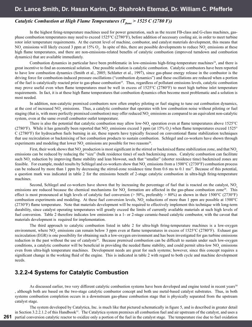
in the catalytic reactor induces gas-phase autoignition in the downstream gas-phase combustion stage, where combustion is completed. The catalyst stage is operated fuel-lean and uses a Pd-based catalyst. A preburner is generally employed to ensure that the catalyst remains active (lit off) during low-emissions engine operation. The system developed by Precision Combustion, Inc. is shown schematically in figure 6, as originally developed for operation on natural gas32. This system is described in greater detail in Section 3.2.2.1.1 of this Handbook. Briefly, the Precision Combustion system is based on fuel-rich operation of the catalyst, and sustains fuel-lean gas-phase combustion downstream of the catalyst via recirculation-based flameholding. All the fuel and part of the air pass through the catalyst with the remainder of the air providing catalyst cooling. This cooling air then mixes with the catalyst effluent establishing a fuel lean flame. Fuel-rich operation of the catalyst provides greater catalyst activity than fuel-lean operation, such that a preburner is not normally required during low-emissions engine operation. Flashback and autoignition issues are also precluded because fuel oxidation and heat release in the catalyst stage are limited by available oxygen, and the system can therefore be operated safely even at the highest desired combustion-stage temperatures. Fuel-rich operation also allows similar catalyst and reactor performance with widely varying fuel types, since catalyst-stage reactions are starved of oxygen, thereby limiting the extent of fuel oxidation and heat release regardless of the fuel’s intrinsic reactivity on the catalyst. The system has been successfully tested on multiple fuels, including Diesel No. 2, simulated refinery fuel gas and syngas, and other low-Btu fuels. Catalytic combustion systems can also be combined with non-catalytic lean-premixed systems to offer unique capabilities in terms of performance, cost, pressure drop, and space requirements. For example, Precision Combustion, Inc. has developed a catalytic pilot system that combines its RCL system with non-catalytic swirl-based fuel/air injection. This system has been tested in cooperation with Solar Turbines and is described by Karim and co-workers33.
3.2.2-5 Challenges for Catalytic Combustion
While the art and science of chemical reactor design using heterogeneous catalysis is well known, the application of this technology to catalytic combustion has required significant development efforts due to both the exothermicity of combustion and the operational needs of gas turbine engines. A catalytic process for a gas turbine engine must contend with rapid heat release and high operating temperatures, variable feed composition (fuel/air ratio may change, and fuel quality and composition may vary), variable thermodynamic conditions (inlet pressure and temperature), and variable reactor residence time (space velocity). To provide this flexibility, the catalytic combustor is not generally required to maximize yield or selectivity to a particular product; instead, the catalyst is required to provide stability to a combustion process, usually by providing a temperature rise to a fuel/air mixture. For catalytic combustion, the overriding constraints are robustness and controlled catalyst temperatures over the wide operating range of the engine.
For natural gas combustion, these challenges have been met and initial engine demonstrations have successfully shown that catalytic combustion is capable of driving a gas turbine engine and delivering ultra-low NOx emissions. For other fuels, however, further development and demonstration is required. For catalytic combustion of liquid fuels such as Diesel No. 2, development of an adequate and robust prevaporizer technology is required to prevent wetting of the catalyst surface and to allow reaction of mixed, prevaporized fuel and air on the catalyst surface. For solid fuels such as coal, gasification is required upstream of the catalyst, and there has been growing interest in catalytic combustion of gasified coal or syngas. Because high-hydrogen fuels such as coal-derived syngas are prone to autoignition and flashback, lean-premixed combustion has not been adopted for low-emissions combustion of these fuels34. Instead, non-premixed combustion is used, and diluents such as nitrogen, water, and/or carbon dioxide have been used to reduce flame temperatures and therefore NOx emissions35. Unfortunately, flame stability issues arise at high dilution levels, and NOx emissions below 3 ppm (at 15% O2) have not been reported for non-catalytic syngas combustion. Catalytic combustion, however, can stabilize combustion at lower flame temperatures, or with increased levels of dilution, and offers the potential for IGCC plant emissions below 3 ppm. Precision Combustion, Inc. under contract to DOE has recently demonstrated NOx emissions below 3 ppm in high-pressure, sub-scale catalytic combustion rig tests simulating Tampa Electric’s Polk Power plant operating conditions. However, further development is required to bring this technology to an engine, and eventually to commercialization. As with conventional combustion of syngas, and especially after diluent addition, the very low Lower Heating Values (LHV) of such fuels means that a very high volume flow of fuel is required. For catalytic combustion, this high volume flow must be accommodated within the catalytic reactor, and this raises issues of catalyst size and pressure drop, possibly requiring system level re-design and re-development of the catalytic combustor.
3.2.2 Catalytic Combustion
Combustion
FuelPremixer Catalytic
ReactorPost-Catalyst
Mixing
CatalystCooling
Air Burned Gas
Fig. 6. Schematic of Precision Combustion’s two-stage catalytic combustion system, as originally developed for operation on natural gas. Fuel-rich catalyst effluent mixes with catalyst cooling air prior to fuel-lean gas-phase combustion, and the system is therefore called Rich-Catalytic Lean-burn combustion (trademarked as RCL by Precision Combustion, Inc.)
263
The propensity for high-hydrogen fuels to autoignite, together with their wide flammability limits, require special attention to premixing design. In addition, syngas fuels carry trace levels of catalyst contaminants that may affect long-term catalyst durability, and this needs to be examined and remediated if problematic. Long-term durability tests are required, preferably in an actual syngas slipstream at an operating IGCC plant, where real contaminants will be present.
3.2.2-6 Conclusions
Catalytic combustion has been established as providing low NOx emissions for modern gas turbines along with subsequent reduction in combustion dynamics and improved operability. Feasibility of catalytic combustion has been established for both high and low firing temperature gas turbines. For natural gas combustion, the challenges of catalytic combustion have been met and initial engine demonstrations have successfully shown that catalytic combustion is capable of driving a gas turbine engine and delivering ultra-low NOx emissions. Further field trials and engine operating experience will advance the catalytic combustion applications for gas turbines. For alternative fuels, particularly coal-derived syngas, further development is required; but, initial demonstrations have shown the potential for ultra-low emissions catalytic combustion in future IGCC power plants. In recent years, metal catalyst substrates have been adopted, together with a two-stage approach to catalytic combustion that maintains catalyst temperatures within their material limits. In addition, the two-stage approach allows gas-phase combustion temperatures to rise to the levels needed for good combustion efficiency and high efficiency turbine operation. Prior material limitations have been largely resolved through design concepts such as reactor backside cooling and reactor mode of operation as well as availability of high temperature metal alloys. Multiple approaches to catalytic combustion have been pursued over the years in the quest for ultra-low NOx emissions from power generating gas turbines. Low, single digit, NOx emissions with low combustion dynamics have been demonstrated in engine environments permitting a wider operating regime from part load to full load conditions. These benefits make catalytic combustion a viable, low cost approach as compared to selective catalytic reduction (SCR) to meet the low emissions requirements.
3.2.2-7 Notes________________________
1. W.C. Pfefferle, R.V. Carruba, R.M. Heck, and G.W. Roberts, “Catathermal Combustion: A New Process for Low Emissions Fuel Conversion,” ASME Paper No. 75-WA/Fu-1(1975).2. Ibid.3. D.N. Anderson, R.R. Tacina, and T.S. Mroz, “Performance of a Catalytic Reactor at Simulated Gas Turbine Operating Conditions,” NASA Technical Memorandum X-71747(1975); J.P. Kesselring, W.V. Krill, E.K. Chu, and R.M. Kendall. In proceedings of New fuels and advances in combustion technologies symposium, Mar. 26-30, 1979, New Orleans, LA; P.W. Pillsbury, “Update of Full- Scale Catalytic Burner Testing for Combustion Turbines,” ASME Paper No. 84-GT-54 (1984); T.J. Rosfjord, AIAA Paper No. 76- 46 (Washington DC, Jan. 1976).4. R.A. Dalla Betta et al., Journal of Engineering for Gas Turbines and Power 119 (1997):, 844-851; P. Dutta, D.K. Yee, and R.A. Dalla Betta, ASME Paper No. 97-GT-497 (1997); S. Etemad, H. Karim, L.L. Smith, and W.C. Pfefferle, “Advanced Technology Catalytic Combustor for High Temperature Ground Power Gas Turbine Applications,” Catalysis Today 47 (1999): 305-313; D.A. Smith, S.F. Frey, D.M. Stansel, and M.K. Razdan, ASME Paper No. 97-GT-311(1997).5. R.A. Dalla Betta, T. Shoji, D.K. Yee, and S.A. Magno. Catalyst Structure Employing Integral Heat Exchange. U.S. Patent 5,512,250; R.A. Dalla Betta, N. Ezawa, K. Tsurumi, J.C. Schlatter, and S.G. Nickolas, “Two Stage Process for Combusting Fuel Mixtures,” U.S. Patent No. 5,183,401 (1993); W.C. Pfefferle, L.L. Smith, and M.J. Castaldi, “Method and Apparatus for a Fuel- Rich Catalytic Reactor,” U.S. Patent No. 6,358,040 (2002).6. D.K. Yee, K. Lundberg, and C.K. Weakley, “Field Demonstration of a 1.5 MW Gas Turbine with a Low Emissions Catalytic Combustion System,” Journal of Engineering for Gas Turbines and Power 123 (2001): 550-556; L.L. Smith, H. Karim, M.J. Castaldi, S. Etemad, W.C. Pfefferle, V.K. Khanna, and K.O. Smith, “Rich-Catalytic Lean-Burn Combustion for Low-Single-Digit NOx Gas Turbines,” Journal of Engineering for Gas Turbines and Power 127 (2005): 27-35.7. G. Leonard and J. Stegmaier, “Development of an Aeroderivative Gas Turbine Dry Low Emissions Combustion System,” Journal of Engineering for Gas Turbines and Power 116 (1994): 542-546.
8. E.M. Johansson, D. Papadias, P.O. Thevenin, A.G. Ersson, R. Gabrielsson, P.G. Menon, P.H. Bjornbom and S.G. Jaras, “Catalytic Combustion for Gas Turbine Applications,” Catalysis 14 (1999): 183-235; R.E. Hayes and S.T. Kolaczkowski, Introduction to Catalytic Combustion (Amsterdam:Gordon and Breach Science Publishers, 1997); D. Anson, M. DeCorso and W.P. Parks, “Catalytic Combustion for Industrial Gas Turbines,” International Journal of Energy Research 20 (1996): 693-711; S.T. Kolaczkowski, “Catalytic Stationary Gas Turbine Combustors: A Review of the Challenges Faced to Clear the Next Set of Hurdles,” Trans. I. Chem. E. 73 Part A (1995): 168-190.
Dr. Lance Smith, Dr. Hasan Karim, Dr. Shahrokh Etemad, Dr. William C. Pfefferle

264264
9. J.G. McCarty, “Kinetics of PdO Combustion Catalysis,” Catalysis Today 26 (1995): 283-293; R. Burch and P.K. Loader, “Investigation of Pt/Al2O3 and Pd/Al2O3 Catalysts for the Combustion of Methane at Low Concentrations,” Applied Catalysis B: Environmental 5 (1994): 149-164; R.J. Farrauto, M.C. Hobson, T. Kennelly, and E.M. Waterman, “Catalytic Chemistry of Supported Palladium for Combustion of Methane,” Applied Catalysis A: General 81 (1992): 227-237; T. Kennelly and R.J. Farrauto, “Catalytic Combustion Process Using Supported Palladium Oxide Catalysts,” U.S. Patent No. 5,216,875 (1993); R.A. Dalla Betta, K. Tsurumi, and T. Shoji, “Graded Palladium-Containing Partial Combustion Catalyst and a Process for Using It,” U.S. Patent No. 5,248,251 (1993).10. L.D. Pfefferle and W.C. Pfefferle, “Catalysis in Combustion,” Catal. Rev.-Sci. Eng. 29 (1987): 219-267.11. W.S. Blazowski and D.E. Walsh, “Catalytic Combustion: An Important Consideration for Future Applications,” Combustion Science and Technology 10 (1975): 253-244; P. Forzatti and G. Groppi, “Catalytic Combustion for the Production of Energy,” Catalysis Today 54 (1999): 165-180; J.H. Lee and D.L. Trimm, “Catalytic Combustion of Methane,” Fuel Processing Technology 42 (1995): 339-359; F.H. Ribeiro, M. Chow, and R.A. Dalla Betta (1994). J. Catal., 146 (1994): 537.l2. See note 8 above (Johansson).13. R.A. Dalla Betta, “Catalytic Combustion Gas Turbine Systems: The Preferred Technology for Low Emissions Electric Power Production and Co-generation,” Catalysis Today 35 (1997): 129-135.14. R.J. Farrauto, J.K. Lampert, M.C. Hobson, and E.M. Waterman, “Thermal Decomposition and Reformation of PdO Catalysts; Support Effects,” Applied Catalysis B: Environmental 6 (1995): 263-270; T. Furuya, K. Sasaki, Y. Hanakata, T. Ohhashi, M. Yamada, T. Tsuchiya, and Y. Furuse, “Development of a Hybrid Catalytic Combustor for a 1300°C Class Gas Turbine,” Catalysis Today 26 (1995): 345-350; Y. Ozawa, Y. Tochihara, N. Mori, I. Yuri, T. Kanazawa, and K. Sagimori, “High Pressure Test Results of a Catalytically Assisted Ceramic Combustor for a Gas Turbine,” ASME Paper No. 98-GT-381 (Stockholm, Sweden, 2-5 June 1998); N.M. Rodriguez, S.G. Oh, R.A. Dalla-Betta, and R.T.K. Baker, “In Situ Electron Microscopy Studies of Palladium Supported on Al2O3, SiO2, and ZrO2 in Oxygen,” J. Catalysis 157 (1995): 676-686; R. Carroni, V. Schmidt, and T. Griffi n, “Catalytic Combustion for Power Generation,” Catalysis Today 75 (2002): 287-295.15. D.B. Fant, G.S. Jackson, H. Karim, D.M. Newburry, P. Dutta, K.O. Smith, and R.W. Dibble, “Status of Catalytic Combustion R&D for the Department of Energy Advanced Turbine Systems Program,” Journal of Engineering for Gas Turbines and Power 122 (2000): 293-300.16. M. Lyubovsky, L.L. Smith, M. Castaldi, H. Karim, B. Nentwick, S. Etemad, R. LaPierre, and W.C. Pfefferle, “Catalytic Combustion over Platinum Group Catalysts: Fuel-Lean versus Fuel-Rich Operation,” Catalysis Today 83 (2003): 71-84.17. M. Lyubovsky, private communication (2005).18. T.C. Paul, R.W. Schonewald, and P.J. Marolda, “Power Systems for the 21st Century – H Gas Turbine Combined Cycles,” General Electric Power Systems Report No. GER-3935A (1996).19. C.T. Bowman, “Control of Combustion-Generated Nitrogen Oxide Emissions: Technology Driven by Regulations,” in proceedings of Twenty-Fourth Symposium (International) on Combustion (1992): 859-878; S.M. Correa, “A Review of NOx Formation Under Gas-Turbine Combustion Conditions,” Combustion Science and Technology 87 (1992): 329-362.20. See note 2 above.21. See note 6 above. 22. R. Eldrid, L. Kaufman, and P. Marks, “The 7FB: The Next Evolution of the F Gas Turbine,” General Electric Power Systems Report No. GER-4194 (2001); also, see note 18 above.23. See note 6 above (Smith).24. D.E. Hobson, J.E. Fackrell, and G. Hewitt, “Combustion Instabilities in Industrial Gas Turbines – Measurements on Operating Plant and Thermoacoustic Modelling,” Journal of Engineering for Gas Turbines and Power 122 (2000): 420-428; T. Lieuwen and K. McManus, “Introduction: Combustion Dynamics in Lean-Premixed Prevaporized (LPP) Gas Turbines,” Journal of Propulsion and Power 19 (2003): 721; H.C. Mongia, T.J. Held, G.C. Hsiao, and R.P. Pandalai, “Challenges and Progess in Controlling Dynamics in Gas Turbine Combustors,” Journal of Propulsion and Power 19 (2003): 822-829.25. J.C. Schlatter, R.A. Dalla Betta, S.G. Nickolas, M.B. Cutrone, K.W. Beebe, and T. Tsuchiya, “Single-Digit Emissions in a Full- Scale Catalytic Combustor,” ASME Paper No. 97-GT-57 (1997); also see note 6 above.26. A. Schlegel, P. Benz, T. Griffi n, W. Weisenstein, and H. Bockhorn, “Catalytic Stabilization of Lean Premixed Combustion: Method for Improving NOx Emissions,” Combustion and Flame 105 (1996): 332-340.27. Ibid. 28. Ibid. 29. K.K. Botros, G.R. Price, and G. Kibrya, “Thermodynamic, Environmental and Economic Assessment of Exhaust Gas Recirculation for NOx Reduction in Gas Turbine Based Compressor Station,” ASME Paper No. 99-GT-173 (1999).30. See note 6 above.31. See note 5 above. 32. See note 5 above (Pfefferle). 33. H. Karim, K. Lyle, S. Etemad, L.L. Smith, W.C. Pfefferle, P. Dutta, and K. Smith. “Advanced Catalytic Pilot for Low NOx Industrial Gas Turbines,” Journal of Engineering for Gas Turbines and Power 125 (2003): 879-884.34. R.M. Jones and N.Z. Shilling, “IGCC Gas Turbines for Refi nery Applications,” General Electric Power Systems Report No. GER-4219 (2003).35. Ibid.
3.2.2 Catalytic Combustion

3.2.2 Catalytic Combustion & 3.2.2.1 Fuel-Rich Catalytic Combustion
Dr. Lance L. Smith is a senior research & development engineer in the Gas Turbine Products group at Precision Combustion, Inc. (PCI), and a visiting assistant professor in the Engineering Department at Trinity College. Dr. Smith has 14 years experience in combustion research and combustor development, including work in turbulent non-premixed combustion, premixed combustion and premixing, aerodynamic design of combustor components, pulsed combustion, and catalytic combustion. His academic research has been primarily experimental, with a focus on laser-based measurements in fl ames, including work conducted as a visiting researcher at Sandia National Laboratories and as a post-doctoral researcher at UCLA. Dr. Smith is a principal engineer of, and holds multiple patents for, the RCLTM catalytic reactor. At PCI, he works with OEM gas turbine manufacturers to develop integrated catalytic combustion systems for ultra-low emissions gas turbines. A graduate of Brown University (B.S., 1986) and of University of California, Berkeley (M.S., 1990 and Ph.D., 1994), Dr. Smith is an elected member of the Tau Beta Pi and Sigma Xi honor societies, and a member of the Combustion Institute.
Dr. Lance L. Smith
Gas Turbine Group, Precision Combustion, Inc.410 Sackett Point Road, North Haven, CT 06473
BIOGRAPHY
Dr. Shahrokh Etemad
Gas Turbine Group, Precision Combustion, Inc.410 Sackett Point Road, North Haven, CT 06473
phone: (203) 287-3700 x217email: [email protected]
Dr. Shahrokh Etemad as Manager of Gas Turbine Products at Precision Combustion, Inc. (PCI) in North Haven, Connecticut, has full responsibility for technical and commercial development of two major products. He manages an advanced technology group to develop low-emissions combustion products in close collaboration with several OEM gas turbine engine manufacturers and the U.S. Department of Energy. Dr. Etemad is responsible for budgeting, funding opportunities, technology direction, proposal preparation and complete R&D operations including concept development, computational analysis, experimental testing, full-size performance demonstration and productionization. Prior to his present position at PCI, he worked for several years at Textron Lycoming and United Technologies, Carrier. Dr. Etemad has published 28 technical articles and holds 28 patents in the field of turbomachinery, combustion, and thermofluid systems. He earned bachelor’s and master’s degrees at Sussex University and University of London respectively, and received his Ph.D. from the University of Washington in 1984. He has been a member of ASME since 1995 and won the 2003 ASME Gas Turbine award.

Dr. Hasan Karim is a senior research & development engineer at Precision Combustion, Inc. (PCI), where his responsibilities include design, development, analysis, numerical and computational fluid dynamics, and testing of catalytic combustors for natural gas, syngas, and liquid fuel. He is the principal investigator for the catalytic combustor development project for the U.S. Navy and lead engineer for the catalytic pilot and catalytic combustor for downhole combustion programs. After receiving a bachelor’s degree from Indian Institute of Technology-Kharagpur in 1987, Dr. Karim earned his M.S. from New Jersey Institute of Technology in 1991, and his Ph.D. from Yale University in 1998. He is a co-inventor of air-cooled rich and lean reactor technology.
Dr. Hasan Karim
Gas Turbine Group, Precision Combustion, Inc.410 Sackett Point Road, North Haven, CT 06473

Dr. William C. Pfefferle
Gas Turbine Group, Precision Combustion, Inc.410 Sackett Point Road, North Haven, CT 06473
Dr. William C. Pfefferle invented the original catalytic combustor for gas turbine engines in the early 1970s and now holds over 90 U.S. patents. In 1986, Dr. Pfefferle co-founded Precision Combustion, Inc. (PCI), a Connecticut-based company dedicated to developing clean and effi cient technology for clean air. His research has led to important industrial advances such as the RCL catalytic combustor for ground power gas turbine engines, which is now in late-stage development and evaluation by several major gas turbine manufacturers, and the Microlith catalytic reaction system, which forms the basis for paradigm-shift, high heat mass transfer catalytic reactors for fast-lightoff automotive catalytic converters and fuel processor reactors. With a B.S. in Chemical Engineering from Drexel University (1944) and a Ph.D. in Physical Chemistry from the University of Pennsylvania (1952), Dr. Pfefferle is a member of the American Chemical Society (ACS), and received the ACS 31st Northeast Regional Industrial Innovation Award. He was inducted into the New Jersey Inventor’s Hall of Fame in February 1990. He continues to work full-time to develop catalytic devices for clean and effi cient energy.