gte analog data sheet - mtssensors.com
TRANSCRIPT
– Offers redundancy for Enhanced Safety Applications (ESA)– Embeddable for added protection in harsh environments– ATEX- / IECEx- certifi cation (optionally)
GTE AnalogData sheet
Magnetostrictive Linear Position Sensors
2
Temposonics® GTE Analog ATEX / NEC / CECData Sheet
5
3
1
2
4
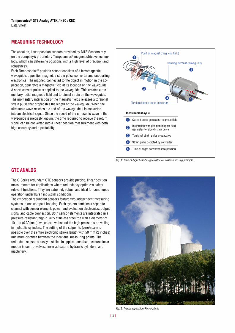
Measurement cycle
1 Current pulse generates magnetic fi eld
2 Interaction with position magnet fi eld generates torsional strain pulse
3 Torsional strain pulse propagates
4 Strain pulse detected by converter
5 Time-of-fl ight converted into position
Sensing element (waveguide)
Position magnet (magnetic fi eld)
Torsional strain pulse converter
Fig. 1: Time-of-flight based magnetostrictive position sensing principle
Fig. 2: Typical application: Power plants
MEASURING TECHNOLOGY
The absolute, linear position sensors provided by MTS Sensors rely on the company’s proprietary Temposonics® magnetostrictive techno-logy, which can determine positions with a high level of precision and robustness.Each Temposonics® position sensor consists of a ferromagnetic waveguide, a position magnet, a strain pulse converter and supporting electronics. The magnet, connected to the object in motion in the ap-plication, generates a magnetic fi eld at its location on the waveguide. A short current pulse is applied to the waveguide. This creates a mo-mentary radial magnetic fi eld and torsional strain on the waveguide. The momentary interaction of the magnetic fi elds releases a torsional strain pulse that propagates the length of the waveguide. When the ultrasonic wave reaches the end of the waveguide it is converted into an electrical signal. Since the speed of the ultrasonic wave in the waveguide is precisely known, the time required to receive the return signal can be converted into a linear position measurement with both high accuracy and repeatability.
GTE ANALOG
The G-Series redundant GTE sensors provide precise, linear position measurement for applications where redundancy optimizes safety relevant functions. They are extremely robust and ideal for continuous operation under harsh industrial conditions. The embedded redundant sensors feature two independent measuring systems in one compact housing. Each system contains a separate channel with sensor element, power and evaluation electronics, output signal and cable connection. Both sensor elements are integrated in a pressure-resistant, high-quality stainless steel rod with a diameter of 10 mm (0.39 inch), which can withstand the high pressures prevailing in hydraulic cylinders. The setting of the setpoints (zero/span) is possible over the entire electronic stroke length with 50 mm (2 inches) minimum distance between the individual measuring points. The redundant sensor is easily installed in applications that measure linear motion in control valves, linear actuators, hydraulic cylinders, and machinery.

3
Temposonics® GTE Analog ATEX / NEC / CECData Sheet
TECHNICAL DATA
OutputVoltage 0…10 VDC, 10…0 VDC, −10…+10 VDC, +10…−10 VDC
(minimum controller load: > 5k Ω)Current 4…20 mA, 20…4 mA, 0…20 mA, 20…0 mA
(minimum/maximum load: 0/500 Ω)Measured value Position
Measurement parametersResolution: Position Infinite (restricted by output ripple)
Cycle time < 1 ms (typical)
Linearity deviation < ±0.02 % F.S. (minimum ±50 μm)
Repeatability < ±0.001 % F.S. (minimum ±2.5 µm)
Hysteresis < 4 µm
Operating conditionsOperating temperature –40…+75 °C (−40…+167 °F) Humidity 90 % relative humidity, no condensation
Ingress protection IP64
Shock test 100 g (single shock) according to IEC 60068-2-27 (survivability)
Vibration test 10 g/10…2000 Hz according to IEC60068-2-6 (resonance frequencies excluded)EMC test Electromagnetic emission according to EN 61326-1 and EN 55011
Electromagnetic immunity according to EN 61326-1The sensor meets the requirements of the EU directives and is marked with
Operating pressure 350 bar static (5076 psi static), 690 bar peak (10,000 psi peak)
Agency approvals (Optional)Non-sparking Class I Zone 2 AEx/Ex nA IIC T4 Gc
Class II / III Zone 22 AEx tc / Ex tc IIC T130 °C Dc Class I / II / III Div 2 T4 ABCDEFG II 3G Ex nA IIC T4 Gc IECEx BVS 13.0063X –20 °C ≤ Tamb ≤ +75 °C (–4 °F ≤ Tamb ≤ +167 °F)
Design / MaterialSensor electronics housing Stainless steel 1.4305 (AISI 303)
Sensor rod Stainless steel 1.4306 (AISI 304L)
Stroke length 50…2540 mm (2…100 in.)
Mechanical mountingMounting position Any
Mounting instruction Please consult the technical drawing on page 4
Electrical connectionConnection type Cable output
Operating voltage +24 VDC (−15/+20 %)
Current consumption 100 mA typical per channel
Dielectric strength 700 VDC (DC ground to machine ground)
Polarity protection Up to −30 VDC
Overvoltage protection Up to 36 VDC
LR1346-4

4
Temposonics® GTE Analog ATEX / NEC / CECData Sheet
Controlling design dimensions are in millimeters and measurements in ( ) are in inches
Certifi cation required GTE-xxxxx-Bxx-1-xx-EX (+24 VDC (–15/+20 %))
IECEx / ATEX(IECEx: Global market;
ATEX: Europe)
Ex nA IIC T4 GcZone 2−40 °C ≤ Ta ≤ +75 °C (−40 °F ≤ Ta ≤ +167 °F)
NEC(USA)
Class I/II/III Div 2 T4Groups ABCDEFGClass I, Zone 2, AEx nA IIC T4 Class II/III, Zone 22, AEx tc IIC T130 °C–20 °C ≤ Ta ≤ +75 °C (−4 °F ≤ Ta ≤ +167 °F)
CEC(Canada)
Class I/II/III Div 2 T4Groups ABCDEFGEx nA IIC T4 Gc Ex tc IIC T130 °C Dc –20 °C ≤ Ta ≤ +75 °C (−4 °F ≤ Ta ≤ +167 °F)
CERTIFICATIONS
Fig. 3: Certifications GTE Analog
TECHNICAL DRAWING
GTE Analog
Mag
net
3.4(0.13)
TPV cable,part no. 530 162bending radius: 5 × D
13(0.51)
Null zone37.5
(1.48)
Stroke length50…2540(2…100)
Dead zone63.5(2.5)
4(0.16)
Ø 25(Ø 1) Ø 48
(Ø 0.19)Ø
10(Ø
0.4
)Ø 60
f7(Ø
2.3
6 f7
)
19.2(0.76)
4.5(0.18)
Ø 60 f7(Ø 2.36 f7)
28(1.1)
20.3 (0.8)
14 (0.55)
Sensor electronics housing56.8
(2.24)
Fig. 4: Temposonics® GTE with ring magnet

5
Temposonics® GTE Analog ATEX / NEC / CECData Sheet
FREQUENTLY ORDERED ACCESSORIES – Additional options available in our Accessories Guide 551444
CONNECTOR WIRING
Fig. 5: Connector wiring
BXX
Signal + power supply
Cable Color Function
GY Position
PK Signal ground
YE Programming (RS-485 +)
GN Programming (RS-485 −)
BN Supply voltage
WH DC Ground (0 V)
Shield Only connected on controller side
Position magnets Magnet spacer
Ø 32.8(Ø 1.29)
Ø 23.8(Ø 0.94)
Ø 13.5(Ø 0.53)
Ø 4.3(Ø 0.17)
60°
140°
3 (0.1
2)
7.9(0.31)
Ø 32.8(Ø 1.29)
Ø 23.8(Ø 0.94)
Ø 13.5(Ø 0.53)
Ø 4.3(Ø 0.17)
7.9(0.31)
Ø 25.4(Ø 1)
Ø 13.5(Ø 0.53) 7.9
(0.31) Ø 14.3(Ø 0.56)
Ø 23.8(Ø 0.94)
Ø 31.8(Ø 1.25)
Ø 4.3(Ø 0.17)
3.2(0.13)
U-magnet OD33Part no. 251 416-2
Ring magnet OD33Part no. 201 542-2
Ring magnet OD25.4Part no. 400 533
Magnet spacerPart no. 400 633
Material: PA ferrite GF20Weight: Approx. 11 gSurface pressure: Max. 40 N/mm2
Fastening torque for M4 screws: 1 NmOperating temperature: −40…+105 °C (−40…+221 °F)
Material: PA ferrite GF20Weight: Approx. 14 gSurface pressure: Max. 40 N/mm2
Fastening torque for M4 screws: 1 NmOperating temperature: −40…+105 °C (−40…+221 °F)
Material: PA ferriteWeight: Approx. 10 gSurface pressure: Max. 40 N/mm2
Operating temperature: −40…+105 °C (−40…+221 °F)
Material: Aluminum Weight: Approx. 5 gSurface pressure: Max. 20 N/mm2
Fastening torque for M4 screws: 1 Nm
Programming tool
Hand programmer for analog outputPart no. 253 853
Easy teach-in-setups of stroke lengthand direction on desired zero / spanpositions. For sensors with 1 magnet.
Controlling design dimensions are in millimeters and measurements in ( ) are in inches

6
Temposonics® GTE Analog ATEX / NEC / CECData Sheet
ORDER CODE
Manuals, Certificates, Software & 3D Models available at: www.mtssensors.com
1 2 3 4 5 6 7 8 9 10 11 12 13 14 15 16
G T E B 0 1
a b c d e foptional
a Sensor model
G T E Embedded pressure-fi t fl ange Ø 60 mm (2.36 in.)
b Stroke length
X X X X M 0050…2540 mm
Standard stroke length (mm) Ordering steps
50… 500 mm 5 mm
500… 750 mm 10 mm
750…1000 mm 25 mm
1000…2540 mm 50 mm
X X X X U 002.0…100.0 in.
Standard stroke length (in.) Ordering steps
2… 20 in. 0.2 in.
20… 30 in. 0.4 in.
30… 40 in. 1.0 in.
40…100 in. 2.0 in.
Non-standard stroke lengths are available; must be encoded in 5 mm/0.1 in. increments.
.
c Connection type
B 0 1 1 m/3 ft. TPV cable (part no. 530 162)
B 0 3 3 m/10 ft. TPV cable (part no. 530 162)
B 0 5 5 m/16 ft. TPV cable (part no. 530 162)
d Operating voltage
1 +24 VDC (–15/+20 %) (Tamb max. +75 °C (+167 °F))
e Output
A 0 4…20 mA
A 1 20…4 mA
A 2 0…20 mA
A 3 20…0 mA
V 0 0…+10 VDC
V 1 +10…0 VDC
V 2 −10…+10 VDC
V 3 +10…−10 VDC
Optional:
f Agency approval
E X Approved version
DELIVERY
• Sensor• O-ring• Back-up ring
Accessories have to be ordered separately.
USA MTS Systems Corporation
Sensors DivisionAmerika & APAC Region
3001 Sheldon DriveCary, N.C. 27513Telefon: +1 919 677-0100E-Mail: [email protected]
DEUTSCHLANDMTS Sensor Technologie
GmbH & Co. KGEMEA Region & Indien
Auf dem Schüffel 958513 LüdenscheidTelefon: +49 2351 9587-0E-Mail: [email protected]
ITALIENZweigstelle
Telefon: +39 030 988 3819E-Mail: [email protected]
FRANKREICHZweigstelle
Telefon: +33 1 58 4390-28E-Mail: [email protected]
UKZweigstelle
Telefon: +44 79 44 15 03 00E-Mail: [email protected]
SKANDINAVIENZweigstelle
Telefon: + 46 70 29 91 281E-Mail: [email protected]
CHINAZweigstelle
Telefon: +86 21 2415 1000 / 2415 1001E-Mail: [email protected]
JAPANZweigstelle
Telefon: +81 3 6416 1063E-Mail: [email protected]
www.mtssensors.comMTS, Temposonics und Level Plus sind eingetragene Warenzeichen der MTS Systems Corporation in den USA. MTS Sensors und das MTS Sensors Logo sind Warenzeichen der MTS Systems Corporation in den USA. Diese Warenzeichen können auch in anderen Ländern geschützt sein. Alle anderen Warenzeichen sind im Besitz des jeweiligen Eigentümers. Copyright © 2020 MTS System Corporation. Keine Vergabe von Lizenzen an geistigem Eigentum. MTS behält sich vor, ohne Ankündigung die Informationen in diesem Dokument sowie das Produktdesign zu ändern sowie Produkte aus dem Verkauf zu nehmen. Typografi sche und grafi sche Fehler oder Auslassungen sind unbeabsichtigt. Alle Informationen ohne Gewähr. Auf der Website www.mtssensors.com erhalten Sie die aktuellen Produktinformationen.
Document Part Number: 551386 Revision E (EN) 12/2020