gsx tm graphics extension programmer’s guide · gsx programmer’s guide gsx functions o gsx...
TRANSCRIPT

GSX tm Graphics Extension
Programmer's Guide
Copyright (c) 1983
Digital Research P.O. Box 579
160 Central Avenue Pacific Grove, CA 93950
TWX 91O 360 5001
All Rights Reserved THIS WAS A SCAN FROM A REAL PAPER MANUAL. THE RESULT WAS IN LOTUS AMI PRO 3 AND WAS IMPORTED IN WORD 2000, AFTER MANUAL EDIT STEPS NOW CONVERTED TO PDF FORMAT.

COPYRIGHT Copyright (c) 1983 by Digital Research Inc. All rights reserved. No part of this publication may be reproduced, transmitted, transcribed, stored in a retrieval system, or translated into any language or computer language in any form or by any means, electronic, mechanical, magnetic, optical, chemical, manual, or otherwise, without the prior written permission of Digital Research, Post Office Box 579, Pacific Grove, California, 93950. Readers are granted permission to include the example programs, either in whole or in part, in their own programs. DISCLAIMER Digital Research makes no representations or warranties with respect to the contents hereof and specifically disclaims any implied warranties of merchantability or fitness for any particular purpose. Further, Digital Research reserves the right to revise this publication and to make changes from time to time in the content hereof without obligation of Digital Research to notify any person of such revision or changes. TRADEMARK CP/M and CP/M-86 are registered trademarks of Digital Research. DR Draw, DR Graph, GSX, and TEX are trademarks of Digital Research. IBM is a registered trademark of International Business machines.MS-DOS is a trademark of Microsoft Corporation. The GSX Graphics Extension Programmer's Guide was prepared using the Digital Research TEX" Text Formatter and printed in the United States of America. *********************************** * Second Edition: September 1983 * ***********************************
Foreword MANUAL OBJECTIVE This document describes the features and operation of the Graphics System Extension (GSX tm ) , Release 1. 2. The manual explains what GSX does and how you can use its graphics capabilities. It also explains how GSX interfaces to your hardware environment and how you can adapt GSX for your own unique graphics devices. INTENDED AUDIENCE This manual is intended for microcomputer programmers as well as for system and application programmers who are familiar with operating system and graphics programming concepts. MANUAL DESIGN This manual contains five sections, three appendixes, a glossary, and an index. The following descriptions will help you determine a reading path through the manual. Section 1 is an introduction to GSX. It describes the features you need to know to run graphics application programs. Section 2 is a programmer's overview of GSX. It explains the GSX architecture and introduces the components of GSX. It also describes how to use GSX with application programs. Section 3 describes the Graphics Device Operating System (GDOS). Section 4 describes the Graphics Input/output System (GIOS) . It tells how to interface particular graphics devices to GSX to provide device independence for your application program. Section 5 provides details about operating GSX and how to integrate your application program with the GSX facilities. iii

Appendixes contain the following reference information: Appendix A - GSX conventions for the CP/M(r) operating system for 8080 microprocessors Appendix B - GSX conventions for the CP/M- 86k, IBM(r) PC DOS, and MS-DOS" operating systems for 8086 microprocessors Appendix C - The Virtual Device Interface (VDI) specification The glossary follows with terminology unique to GSX. Finally, an extensive index helps you use this document more effectively. iv

Table of Contents 1 Introduction About This Manual 1-1 GSX Benefits 1-1 GSX Functions 1-2 Transforming Points 1-2 Servicing Graphics Requests 1-4 Loading Device Drivers 1-4 2 Programmer's Overview Introduction 2-1 Graphics System Extension Architecture 2-1 Graphics Device Operating System (GDOS) 2-2 Graphics Input/Output System (GIOS) 2-2 Enabling Graphics 2-3 Graphics Mode Initialization 2-3 Application Programs 2-6 3 GDOS Introduction 3-1 GDOS Functions 3-1 Graphics Calls 3-1 Dynamic Loading 3-1 Transforming Points 3-2 GDOS Calling Sequence 3-2 GDOS Opcodes 3-2 Loading GIOS Files 3-6 Assignment Table Format 3-7 Memory Management 3-8 v

Table of Contents (continued) 4 GIOS Introduction 4-1 Purpose of GIOS 4-1 GIOS Functions 4-2 virtual Device interface Specification 4-2 Creating GIOS File 4-4 5 Operating Procedures Introduction 5-1 GSX Distribution Files 5-1 Running Graphics Applications under GSX 5-1 Determining Memory Requirements 5-2 Debugging Graphics Applications under GSX 5-3 Writing a New Device Driver 5-3 Appendixes A GSX Calling Conventions for CP/M Introduction A-1 GSX Skeleton Device Driver A-1 FORMAT A-1 GDOS Calling Conventions A-3 vi
Appendixes (continued) B GSX Calling Conventions for CP/M-86, IBM PC DOS, and MS-DOS Introduction B-1 GDOS Calling Sequence B-1 Invoking Device Drivers B-3 Error Messages B-5 C Virtual Device Interface (VDI) Specification Introduction C-1 Format C-1 Open Workstation C-4 Close Workstation C-9 Clear Workstation C-9 Update Workstation C-10 Escape C-10 ESCAPE: Inquire Addressable Character Cells C-12 ESCAPE: Enter Graphics Mode C-13 ESCAPE: Exit Graphics Mode C-13 ESCAPE: Cursor Up C-14 ESCAPE: Cursor Down C-14 ESCAPE: Cursor Right C-15 ESCAPE: Cursor Left C-15 ESCAPE: Home Cursor C-16 ESCAPE: Erase to End of Screen C-16 ESCAPE: Erase to End of Line C-17 ESCAPE: Direct Cursor Address C-17 ESCAPE: Output Cursor Addressable Text C-18 vii

Appendixes (continued) ESCAPE: Reverse Video On C-19 ESCAPE: Reverse Video Off C-19 ESCAPE: Inquire Current Cursor Address C-20 ESCAPE: Inquire Tablet Status C-20 ESCAPE: Hard Copy C-21 ESCAPE: Place Graphic Cursor at Location C-21 ESCAPE: Remove Last Graphic Cursor C-22 Polyline C-23 Polymarker C-24 Text C-25 Filled Area C-26 Cell Array C-27 Generalized Drawing Primitive (GDP) C-29 Set Character Height C-33 Set Character Up Vector C-34 Set Color Representation C-35 Set Polyline Line Width C-37 Set Polyline Color Index C-37 Set Polymarker Type C-38 Set Polymarker Scale C-39 Set Polymarker Color Index C-40 Set Text Font C-41 Set Text Color Index C-42 Set Fill Interior Style C-43 Set Fill Style Index C-44 Set Fill Color Index C-45 viii

Appendixes (continued) Inquire Color Representation C-46 Inquire Cell Array C-47 Input Locator C-48 Input Valuator C-51 Input Choice C-53 Input String C-55 Set Writing Mode C-57 Set Input Mode C-59 Required Opcode CRT Devices C-60 Required Opcode for Plotters and Printers C-61 Tables and Figures Tables 3-1. GSX Operation Codes 3-3 C-1. Sample Mode Status Returned C-49 C-2. Opcode for CRT Devices C-60 C-3. Opcode for Plotters and Printers C-61 Figures 1-1. GSX Provides Device-Independent Graphics 1-3 2-1. GSX Memory Map 2-5 ix
Section I INTRODUCTION ABOUT THIS MANUAL Section 1 identifies the features of GSX, the Graphics System Extension for your operating system. It explains what GSX does and how to use its graphics functions. This section is for you if you are a new user of GSX. It assumes that your goal is to quickly hook up your application programs to your system's graphics capability. If you are a system or an application programmer familiar with operating system concepts, this section introduces you to GSX. Section 2 through Section 5 provides all the details you need to use GSX with your own unique graphics devices. GSX BENEFITS GSX adds graphics to your operating system, as follows: o GSX supports DR Graph and DR Draw, two products that extend your graphics capability. DR Graph allows you to graph and plot data by making simple menu selections. DR Draw lets you draw complex graphics images. o GSX opens a world of application software. You can run any graphics application program that uses GSX with several 8080 and 8086 microcomputer operating systems. o GSX promotes user portability. The interface between you and GSX is identical to the interface between you and your operating system. 1-1

GSX Programmer's Guide GSX Functions o GSX provides a device-independent software interface for your application programs. You will not need to rewrite your programs if you decide to use a printer instead of a plotter, for example. GSX FUNCTIONS All graphics devices are not alike. Terminals, printers, and plotters draw lines, fill in areas, and produce text differently. With the Graphics System Extension for your operating system, you do not have to worry about device differences, because GSX handles all the differences and lets you talk to the devices through your application program as if the devices were all the same. GSX handles graphics requests and supplies the right program to run the device you are using. Transforming All computer graphics are displayed on a Points coordinate system. GSX's job is to make sure the coordinate system that one device uses matches the coordinate system used by another. For example, with GSX your application program produces the same graphics image on your printer that it does on your CRT. The linetypes and character sizes are the same. 1-2

GSX Programmer's Guide GSX Functions
NOTE : Picture of computer intentionally deleted in the interest of producing a plain ASCII file of this manual.
Figure 1-1. GSX Provides Device-Independent Graphics 1-3

GSX Programmer's Guide GSX Functions Servicing Your application programs work with GSX Graphics through a standard calling sequence. GSX Requests translates these standard calls to fit the peculiarities of each graphics device (a printer or plotter, for example). The translation process makes your application programs device-independent. The programs can run on your system with the graphics device you are using. For details about using GSX, refer to the GSX user's guide for your system. Loading Device Each graphics device is mechanically and Drivers electrically different, and requires a special program to run it. These programs are called device drivers. GSX makes sure the right driver is loaded into memory so you can use the device you specify. End of Section 1 1-4

Section 2 PROGRAMMER'S OVERVIEW INTRODUCTION This section introduces the Graphics System Extension architecture with its components and their functions. Later sections describe each of these parts in detail. GRAPHICS SYSTEM GSX is the Graphics System Extension for EXTENSION microcomputer operating systems. It ARCHITECTURE incorporates graphics capability into the operating system and provides a host and device-independent interface for your application programs. Graphics primitives are provided for implementing graphics applications with reduced programming effort. In addition, GSX enhances program portability by allowing an application to run on any operating system with the GSX option. GSX also promotes programmer portability by providing a common programming interface to graphics that is compatible with the most widely used operating systems. GSX is an integral part of your operating system. Application programs interface to GSX through a standard calling sequence. Drivers for specific graphics devices translate the standard GSX calls to the unique characteristics of the device. In this way, GSX provides device independence, and the peculiarities of the graphics device are not visible to the application program. GSX consists of two parts that work together to give your system graphics capability: o Graphics Device Operating System (GDOS) o Graphics Input/Output System (GIOS) 2-1

GSX Programmer's Guide GSX Architecture Graphics The Graphics Device Operating System (GDOS) Device Operating contains the basic host and device- System (GDOS) independent graphics functions that can be called by your application program. GDOS provides a standard interface to graphics that is constant regardless of specific devices or host hardware, just as the disk operating systems standardize disk interfaces. Your application program accesses GDOS in much the same way that it accesses the disk operating system. GDOS performs coordinate scaling so that your program can specify points in a normalized coordinate space. It uses device-specific information to translate the normalized coordinates into the corresponding values for your particular graphics device. Multiple graphics devices can be supported under GSX within a single application. By referring to devices with a workstation identification number, an application program can send graphics information to any one of several disk-resident devices. GDOS dynamically loads a specific device driver when requested by the application program, overlaying the previous driver. This technique minimizes memory size requirements since only one driver is resident in memory at any time. For details see "LOADING GIOS FILES" in Section 3. Graphics The Graphics Input/Output System (GIOS) is Input/Output similar to any I/O system. It contains the System (GIOS) device-specific code required to interface your particular graphics devices to the GDOS. GIOS consists of a set of device drivers that communicate directly with the graphics devices through the appropriate means. GSX requires a unique device driver for each different graphics device on your system. The term GIOS 2-2

GSX Programmer's Guide GSX Architecture refers to the functional layer in GSX that holds the collection of available device drivers. The particular driver that is loaded into memory when required by your application is called a GIOS file. Although a single program can use several graphics devices, GDOS loads only one GIOS file at a time. GIOS performs the graphics primitives of GSX consistent with the inherent capabilities of your graphics device. In some cases, a device driver emulates standard GDOS capabilities that are not provided by the graphics device hardware. For example, some devices require that dashed lines be simulated by a series of short vectors generated in the device driver. The GSX package contains drivers for many of the most popular graphics devices for microcomputer systems. However, you can install your own custom device driver if necessary. We provide information in Section 4, "GIOS," to help you write your driver. The Virtual Device Interface (VDI) Specification in Appendix C defines all the required functions and parameter conventions. Enabling Graphics A special command allows you to enable and disable graphics functions from the command level of the operating system. This command enables GSX by loading GDOS and the default device driver and establishing the proper links to the operating system to allow an application program to access graphics devices. When GSX is disabled, it relinquishes all system memory space, leaving the maximum memory for non-graphics programs. YOU must initialize GSX with a graphics command before running an application that uses GSX. Refer to your GSX user's guide for the GSX command that your system uses. 2-3

GSX Programmer's Guide Graphics Mode Initialization GRAPHICS MODE Upon entering the graphics mode, the INITIALIZATION operating system performs several actions. First, it brings GDOS into memory along with the default driver, the first device driver listed in the Assignment Table. Next, it calls the GDOS, which intercepts GDOS calls but passes operating system calls to the operating system. Finally, control returns to the operating system command interface module, which waits for the next operator command. Note that a warm start (usually invoked by CTRL-Z) does not disturb the graphics mode initialization. 4D However, a cold start, or hardware reboot, disables GSX, which requires you to execute the GSX command after you reboot the system. Figure 2-1 shows the location of the components of GSX after GSX graphics mode initialization. When graphics mode is disabled, the memory used by GDOS and the GIOS file is made available to user programs, and control is returned to the operating system user interface module. 2-4

GSX Programmer's Guide Graphics Mode Initialization
NOTE : Picture of memory map intentionaly deleted in the interest of producing a plain ASCII file of this manual.
Figure 2-1. GSX Memory Map 2-5
GSX Programmer's Guide Application Programs APPLICATION With appropriate calls to GDOS, you can write PROGRAMS your application programs in assembly language or a high-level language that supports the GSX calling conventions. You can compile or assemble and link programs containing GSX calls in the normal manner. End of Section 2 2- 6

Section 3 GDOS INTRODUCTION This section describes the Graphics Device Operating System (GDOS) in detail, including GDOS functions, the GDOS calling sequence, and how device drivers are loaded. GDOS FUNCTIONS GDOS performs three functions during the execution of a graphics application program: o responds to GSX requests o loads device drivers as required o converts normalized coordinates to device coordinates Graphics Calls An application program accesses GDOS by making calls to the operating system. Refer to Appendixes A and B for GSX conventions for specific operating systems. Dynamic Loading Each time an application program opens a workstation, GDOS determines whether the required device driver is resident in memory. If not, GDOS loads the driver from disk and services the graphics request. 3-1

GSX Programmer's Guide GDOS Functions Transforming The application program passes all graphics Points coordinates to GDOS as Normalized Device Coordinates (NDC) in a range from 0 to 32,767 in both axes. Using information passed from the device driver when the workstation, or device, was opened, GDOS scales the NDC units to the device coordinates. The full scale NDC space is always mapped to the full dimensions of your graphics device in each axis. This ensures that all your graphics information appears on the display surface regardless of the dimensions of the device. GDOS CALLING GSX gives you a standard way to access SEQUENCE graphics capabilities. This accessing method is called the Virtual Device Interface (VDI) because it makes all graphics devices appear "virtually" identical. The implementation of the VDI employs the conventional disk operating system calling sequence. The application program calls GDOS by calling the operating system. For specific operating system calls, refer to Appendixes A and B. The program passes arguments to GDOS in a parameter list, which consists of five arrays: a control array, an array of input parameters, an array of input point coordinates, an array of output parameters, and an array of output point coordinates. The specific graphics function to be performed by GDOS is indicated by an operation code in the parameter list. CDOS OPCODES Table 3-1 summarizes the GDOS opcodes. See Appendix C for a detailed description of all the operation codes including parameters. 3- 2
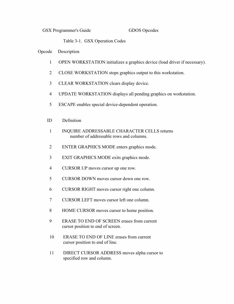
GSX Programmer's Guide GDOS Opcodes Table 3-1. GSX Operation Codes Opcode Description 1 OPEN WORKSTATION initializes a graphics device (load driver if necessary). 2 CLOSE WORKSTATION stops graphics output to this workstation. 3 CLEAR WORKSTATION clears display device. 4 UPDATE WORKSTATION displays all pending graphics on workstation. 5 ESCAPE enables special device-dependent operation. ID Definition 1 INQUIRE ADDRESSABLE CHARACTER CELLS returns number of addressable rows and columns. 2 ENTER GRAPHICS MODE enters graphics mode. 3 EXIT GRAPHICS MODE exits graphics mode. 4 CURSOR UP moves cursor up one row. 5 CURSOR DOWN moves cursor down one row. 6 CURSOR RIGHT moves cursor right one column. 7 CURSOR LEFT moves cursor left one column. 8 HOME CURSOR moves cursor to home position. 9 ERASE TO END OF SCREEN erases from current cursor position to end of screen. 10 ERASE TO END OF LINE erases from current cursor position to end of line. 11 DIRECT CURSOR ADDRESS moves alpha cursor to specified row and column.

3- 3 GSX Programmer's Guide GDOS Opcodes Table 3-1. (continued) Opcode Description 12 OUTPUT CURSOR ADDRESSABI,E TEXT outputs text at the current alpha cursor position. 13 REVERSE VIDEO ON displays subsequent text in reverse video. 14 REVERSE VIDEO OFF displays subsequent text in standard video. 15 INQUIRE CURRENT CURSOR ADDRESS returns location of alpha cursor. 16 INQUIRE TABLET STATUS returns status of graphics tablet. 17 HARDCOPY makes hardcopy. 18 PLACE GRAPHIC CURSOR AT LOCATION moves cursor directly to specified location. 19 REMOVE GRAPHIC CURSOR does not display cursor. 20-50 RESERVED (for future expansion). 51-100 UNUSED (and available). ID Definition 6 POLYLINE outputs a polyline. 7 POLYMARKER outputs markers. 8 TEXT outputs text starting at specified position. 9 FILLED AREA displays and fills a polygon. 10 CELL ARRAY displays a cell array. 3 -4

GSX Programmer's Guide GDOS Opcodes Table 3-1. (continued) Opcode Description 11 GENERALIZED DRAWING PRIMITIVE displays a generalized drawing primitive. ID Definition 1 BAR 2 ARC 3 PIE SLICE 4 CIRCLE 5 PRINT GRAPHIC CHARACTERS 6-7 RESERVED (for future use) 8-10 UNUSED (and available) 12 SET CHARACTER HEIGHT sets text size. 13 SET CHARACTER UP VECTOR sets text direction. 14 SET COLOR REPRESENTATION defines the color associated with a color index. 15 SET POLYLINE LINETYPE sets linestyle for polylines. 16 SET POLYLINE LINEWIDTH sets width of lines. 17 SET POLYLINE COLOR INDEX sets color for polylines. 18 SET POLYMARKER TYPE sets marker type for polymarkers. 19 SET POLYMARKER SCALE sets size for polymarkers. 20 SET POLYMARKER COLOR INDEX sets color for polymarkers. 21 SET TEXT FONT sets device-dependent text style. 3-5

GSX Programmer's Guide GDOS Opcodes Table 3-1. (continued) Opcode Description 22 SET TEXT COLOR INDEX sets color of text. 23 SET FILL INTERIOR STYLE sets interior style for polygon fill (hollow, solid, halftone pattern, hatch). 24 SET FILL STYLE INDEX sets fill style index for polygons. 25 SET FILL COLOR INDEX sets color for polygon fill. 26 INQUIRE COLOR REPRESENTATION returns color representation values of index. 27 INQUIRE CELL ARRAY returns definition of cell array. 28 INPUT LOCATOR returns value of locator. 29 INPUT VALUATOR returns value of valuator. 30 INPUT CHOICE returns value of choice device. 31 INPUT STRING returns character string. 32 SET WRITING MODE sets current writing mode (replace, overstrike, complement, erase). 33 SET INPUT MODE sets input mode (request or sample). LOADING GIOS FILES The GSX Virtual Device Interface refers to graphics devices as workstations. Before a graphics device can be used, it must first be initialized with an OPEN WORKSTATION operation. This operation initializes the device with selected attributes, such as linetype and color. It also returns information about the device to GDOS. 3-6
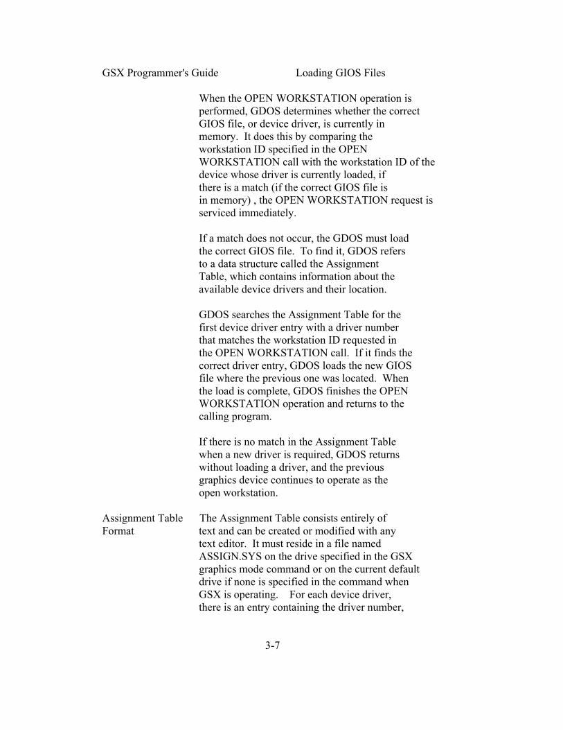
GSX Programmer's Guide Loading GIOS Files When the OPEN WORKSTATION operation is performed, GDOS determines whether the correct GIOS file, or device driver, is currently in memory. It does this by comparing the workstation ID specified in the OPEN WORKSTATION call with the workstation ID of the device whose driver is currently loaded, if there is a match (if the correct GIOS file is in memory) , the OPEN WORKSTATION request is serviced immediately. If a match does not occur, the GDOS must load the correct GIOS file. To find it, GDOS refers to a data structure called the Assignment Table, which contains information about the available device drivers and their location. GDOS searches the Assignment Table for the first device driver entry with a driver number that matches the workstation ID requested in the OPEN WORKSTATION call. If it finds the correct driver entry, GDOS loads the new GIOS file where the previous one was located. When the load is complete, GDOS finishes the OPEN WORKSTATION operation and returns to the calling program. If there is no match in the Assignment Table when a new driver is required, GDOS returns without loading a driver, and the previous graphics device continues to operate as the open workstation. Assignment Table The Assignment Table consists entirely of Format text and can be created or modified with any text editor. It must reside in a file named ASSIGN.SYS on the drive specified in the GSX graphics mode command or on the current default drive if none is specified in the command when GSX is operating. For each device driver, there is an entry containing the driver number, 3-7
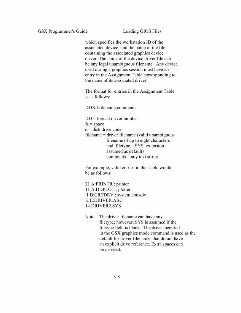
GSX Programmer's Guide Loading GIOS Files which specifies the workstation ID of the associated device, and the name of the file containing the associated graphics device driver. The name of the device driver file can be any legal unambiguous filename. Any device used during a graphics session must have an entry in the Assignment Table corresponding to the name of its associated driver. The format for entries in the Assignment Table is as follows: DDXd:filename;comments DD = logical driver number X = space d = disk drive code filename = driver filename (valid unambiguous filename of up to eight characters and filetype, SYS extension assumed as default) comments = any text string For example, valid entries in the Table would be as follows: 21 A:PRINTR ; printer 11 A:DDPLOT ; plotter 1 B:CRTDRV ; system console 2 E:DRIVER.ABC 14 DRIVER2.SYS Note: The driver filename can have any filetype; however, SYS is assumed if the filetype field is blank. The drive specified in the GSX graphics mode command is used as the default for driver filenames that do not have an explicit drive reference. Extra spaces can be inserted. 3-8

GSX Programmer's Guide Loading GIOS Files The following convention for assigning device driver numbers, or workstation IDs, to graphics devices ensures the maximum degree of device independence within application programs. The convention for driver numbers is as follows: Device Number Device Type 1-10 CRT 11-20 Plotter 21-30 Printer 31-40 Metafile 41-50 Other devices Assign the lowest device number within a device type when you use only one device. Memory Management When graphics mode is enabled, GSX allocates memory for the first device driver in the Assignment Table. This driver is referred to as the default device driver. Subsequently, GDOS causes all new drivers to be loaded into the same area where memory was allotted for the original device driver. Ensure that the first driver in the Assignment Table is the largest driver to be loaded so that ample memory space is allocated by the CSX loader for all subsequent drivers. GSX returns an error to the caller and the new driver is not loaded if an attempt is made to load a driver larger than the default driver. End of Section 3 3-9

Section 4 GIOS INTRODUCTION This section describes the Graphics Input/ Output System, or GIOS. With this information you can write and install your own custom drivers for unique graphic devices. PURPOSE OF GIOS As we discussed earlier, GSX is composed of two components: the Graphics Device Operating System (GDOS) and the Graphics Input/Output System (GTOS) . GDOS contains the device- independent graphics functions, while GIOS contains the device-dependent code. This division is consistent with the philosophy of isolating device dependencies so that the principal parts of the operating system are transportable to many systems. This also allows applications to run independent of the specific devices connected to the system. In this context, GIOS is analogous to the I/O systems but pertains to graphics devices only. GIOS contains a GIOS file, or device driver, for each of the graphics devices on the system. Each GIOS file contains code to communicate with a single specific graphics device. A difference between GIOS and I/O systems is that whereas all device drivers contained within I/O systems are resident in memory simultaneously, only one graphics device driver is resident at any time. That is, only one graphics device is active at a time, although the active device can be changed by a request from the application program. GDOS ensures that the correct driver is in memory when required. 4-1

GSX Programmer's Guide GIOS Functions GIOS FUNCTIONS Each of the GIOS files uses the intrinsic graphics capabilities of devices to implement graphics primitives for GDOS. In some cases, the graphics device does not support all the GDOS operations directly, and the driver must emulate the capability in software. For example, if a plotter cannot produce a dashed line, the driver must emulate it by converting a single dashed line into a series of short vectors and transmitting them to the plotter, giving the same end result. VIRTUAL DEVICE Device drivers must conform to the GSX INTERFACE Virtual Device Interface (VDI) Specification. SPECIFICATION The VDI specifies the calling sequence to access device driver functions as well as the syntax and semantics of the data structures that communicate across the interface. The application program passes arguments to device drivers in a parameter list pointed to by the contents of specific registers. The parameter list is in the form of five arrays, as follows: o control array o array of input parameters o array of input point coordinates o array of output parameters o array of output point coordinates The application program specifies the graphics function to be performed by a device driver with an operation code in the control array. All array elements are type INTEGER (2 bytes). All arrays are 1-based; that is, the double- word address at Parameter Block (PB) points to the first element of the control array (contr I (1) ) .The meaning of the input and output parameter arrays is dependent on the 4-3

GSX Programmer's Guide Virtual Device Specification opcode. See Appendix C, "Virtual Device Interface Specification," for details. The application program passes all graphics coordinates to the device driver as device coordinates. Using information passed from the device driver when the workstation, or device, was opened, GDOS scales the NDC coordinates, passed from the application to the coordinates of the specific device. The full-scale NDC space is always mapped to the full dimensions of your graphics device in each axis. This ensures that all your graphics information is visible on the display surface regardless of the actual device dimensions. However, NDC space is larger than device space. For example, the NDC space for a device is 32K by 32K NDC units. The target device measures 640 by 200 pixels. The size of an NDC pixel is 51 by 164 NDC units. When GSX returns the value of the pixel to an application, the value of the bottom left corner of the NDC pixel is returned by GSX. Therefore, to avoid cumulative errors caused by round-off procedures in your application, you should add an offset of one-half an NDC pixel to the value returned by GSX when you are transforming coordinates up and down GSX. If your device has an aspect ratio that is not 1:1 (that is, the display surface is not square) and you wish to prevent distortion between your world coordinate system and the device coordinate system, your application must use different scaling factors in the x and Y axes to compensate for the asymmetry of your device. For example, if you are using a typical CRT device with an aspect ratio of 3:4 (vertical:horizontal) to produce a perfect 4-3

GSX Programmer's Guide Creating a GIOS File square on the display, you would draw a figure with 4000 NDC units vertically and 3000 NDC units horizontally. That is, the scaling factor for the vertical dimension is 4/3 of the horizontal direction. For most noncritical applications you need not make this adjustment. Details of the Virtual Device Interface, including required and optional functions and arguments, are included in Appendix C, "Virtual Device Interface Specification." CREATING A GIOS Device driver files that are part of GIOS FILE must be in standard executable command format so they can be loaded by GDOS. These files may be renamed to SYS, the default filetype for GSX GIOS files. You can write a device driver in any language as long as the functions and parameter passing conventions conform to the Virtual Device Interface Specification given above. After assembling or compiling your driver source, link it with any required external subroutines and run-time support libraries to produce a load module. The name of a GIOS file can consist of eight characters or less with a SYS filetype. In addition, the driver must be included in the Assignment Table, which is a text file named ASSIGN.SYS on the current default drive. Refer to "Assignment Table Format" in Section 3 for more details about the ASSIGN.SYS and the correct format for each entry. End of Section 4 4- 4
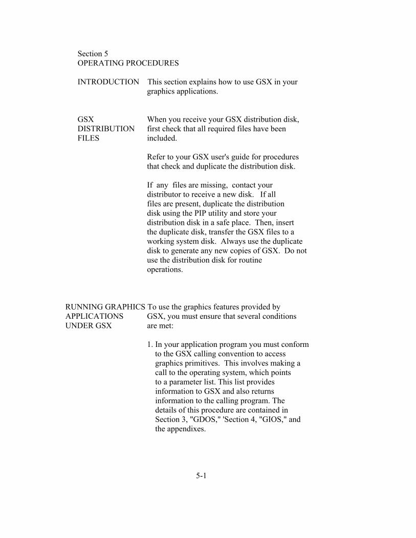
Section 5 OPERATING PROCEDURES INTRODUCTION This section explains how to use GSX in your graphics applications. GSX When you receive your GSX distribution disk, DISTRIBUTION first check that all required files have been FILES included. Refer to your GSX user's guide for procedures that check and duplicate the distribution disk. If any files are missing, contact your distributor to receive a new disk. If all files are present, duplicate the distribution disk using the PIP utility and store your distribution disk in a safe place. Then, insert the duplicate disk, transfer the GSX files to a working system disk. Always use the duplicate disk to generate any new copies of GSX. Do not use the distribution disk for routine operations. RUNNING GRAPHICS To use the graphics features provided by APPLICATIONS GSX, you must ensure that several conditions UNDER GSX are met: 1. In your application program you must conform to the GSX calling convention to access graphics primitives. This involves making a call to the operating system, which points to a parameter list. This list provides information to GSX and also returns information to the calling program. The details of this procedure are contained in Section 3, "GDOS," 'Section 4, "GIOS," and the appendixes. 5-1

GSX Proqrammer's Guide Running Graphics Applications 2. Enough stack space must be available for GSX operations. This includes a buffer area for points passed to GSX and some fixed overhead space. The formula to determine the required stack space is discussed below. 3. The required device drivers must be present on the disk specified in the GSX graphics mode command, or in the current default drive if no drive is specified, when your program is executed. Also, the Assignment Table (ASSIGN.SYS) must contain the names of your device drivers and a logical device number or workstation ID that corresponds to the correct device-driver. The details of device driver and Assignment Table requirements are included in Section 3, "GDOS," and Section 4, "GIOS." 4. After successfully compiling or assembling and linking your application program you can run it just like any other program, but first you must ensure that GSX is active. You can enable GSX graphics with the GSX graphics mode command documented in the GSX user's guide for your system. DETERMINING MEMORY To determine the amount of stack space REQUIREMENTS required to run a given application, make the following calculation: GSX stack requirements: Open workstation call = approximately 500 bytes All others = Ptsin size + 128 Ptsin is the point array passed to the device driver from the application program (two words for each point). 5-2

GSX Programmer's Guide Debugging Graphics Application under GSX The stack requirement is the largest of the two resulting values. This stack space must be available in the application program stack area. The memory required by GDOS is less than 3 kilobytes. This is allocated when the GSX graphics mode command is executed. Space for the default device driver is also allocated at this time. The default device driver should be the largest device driver so that sufficient space is allocated for other drivers loaded during execution of your application. DEBUGGING GRAPHICS Graphics programs can be debugged with a APPLICATIONS debugger, as can any GSX application. The UNDER GSX default device driver and GDOS are loaded after the command has been executed. Your graphics application program is loaded in the normal manner for applications on your operating system. WRITING A NEW GSX is distributed with a number of device DEVICE DRIVER drivers for popular graphics devices. If your devices are included (refer to your GSX user's guide for a summary of the supported devices) , you only need to edit the Assignment Table file with a text editor to ensure that it reflects the logical device number assignments that you desire. However, if your device is not supported, you must create a driver program that conforms to the VDI specification. You can write a driver in any language, but at least part of it is usually implemented in assembler due to the low-level hardware interface required. Your driver must provide the functions listed as required in the VDI specification and must observe the VDI parameter passing conventions. In some cases the capability specified by VDI 5-3

is not available in the graphics device and the function must be emulated by the driver software. For example, dashed lines can be generated by the driver if they are not directly available in the device. The complete VDI specification is in Appendix C, and the parameter passing conventions are discussed in Section 3, "GDOS," and Section 4, "GIOS.11 End of Section 5 5-4
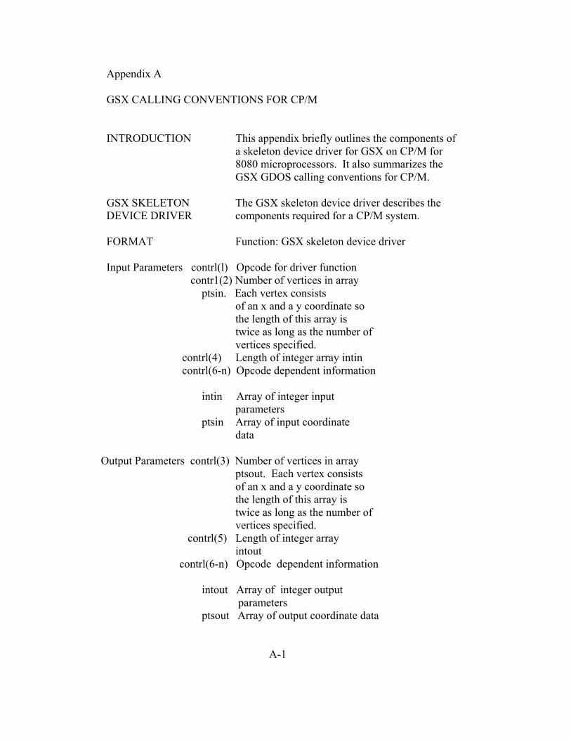
Appendix A GSX CALLING CONVENTIONS FOR CP/M INTRODUCTION This appendix briefly outlines the components of a skeleton device driver for GSX on CP/M for 8080 microprocessors. It also summarizes the GSX GDOS calling conventions for CP/M. GSX SKELETON The GSX skeleton device driver describes the DEVICE DRIVER components required for a CP/M system. FORMAT Function: GSX skeleton device driver Input Parameters contrl(l) Opcode for driver function contr1(2) Number of vertices in array ptsin. Each vertex consists of an x and a y coordinate so the length of this array is twice as long as the number of vertices specified. contrl(4) Length of integer array intin contrl(6-n) Opcode dependent information intin Array of integer input parameters ptsin Array of input coordinate data Output Parameters contrl(3) Number of vertices in array ptsout. Each vertex consists of an x and a y coordinate so the length of this array is twice as long as the number of vertices specified. contrl(5) Length of integer array intout contrl(6-n) Opcode dependent information intout Array of integer output parameters ptsout Array of output coordinate data A-1

GSX Programmer's Guide Format All data passed to the device driver is assumed to be 2-byte INTEGERS. All coordinates passed to GSX are in Normalized Device Coordinates (0-32767 along each axis). These units are mapped to the actual device units (for example, rasters for CRTs or steps for plotters and printers) by GSX so that all coordinates passed to the device driver are in device units. Because both input and output coordinates are converted by GSX, both the calling routine and the device driver must ensure that the input vertex count (contrl(2)) and output vertex count (contrl(3)) are set. The calling routine must set contrl(2) to 0 if no x,y coordinates are being passed to GSX. Similarly, the device driver must set contrl(3) to 0 if no x,y coordinates are being returned through GSX. Because 0-32767 maps to the full extent on each axis, coordinate values are scaled differently on the x and y axes of devices that do not have a square display. The BDOS call to access GSX and the GIOS in CP/M is as follows: BDOS opcode (in C register) for GSX call = 115 Parameter Block (address is passed in DE): PB Address of contrl PB+ls Address of intin PB+2s Address of ptsin PB+3s Address of intout PB+4s Address of ptsout s is the number of bytes used for each argument in the parameter block. For CP/M, this is 2 bytes. A-2

GSX Programmer's Guide Format All opcodes must be recognized, whether they produce any action or not. A list of required opcodes for CRT devices, plotters, and printers follows the specification. These opcodes must be present and perform as specified. All opcodes should be implemented whenever possible because this gives better quality graphics. For CP/M, device driver I/O is done through BDOS (Basic Disk Operating System) calls. CRT devices are assumed to be the console device. Plotters are assumed to be connected as the reader or punch device. Printers are assumed to be connected as the list device. GDOS CALLING The GDOS calling sequence is summarized CONVENTIONS below. Function code (in register C) = 115 Parameter block address in register DE Parameter Block Contents: PB Address of control array PB+2 Address of input parameter array PB+4 Address of input point coordinate array PB+6 Address of output parameter array PB+8 Address of output point coordinate array Control Array on Input: contrl(l) Opcode for driver function contrl(2) Number of vertices in input point array contrl(4) Length of input parameter array contrl(6-n) Opcode dependent A-3
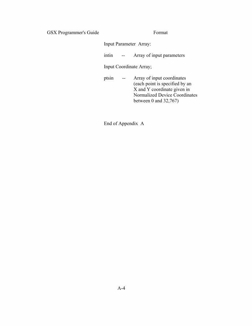
GSX Programmer's Guide Format Input Parameter Array: intin -- Array of input parameters Input Coordinate Array; ptsin -- Array of input coordinates (each point is specified by an X and Y coordinate given in Normalized Device Coordinates between 0 and 32,767) End of Appendix A A-4

Appendix B GSX CALLING CONVENTIONS FOR CP/M, IBM PC DOS, AND MS-DOS INTRODUCTION This appendix outlines the GSX calling sequence for the GDOS, the procedure for invoking device drivers, and error messages when you use GSX on CP/M-86, IBM PC DOS, and MS-DOS. GDOS CALLING The GDOS calling sequence is outlined below. SEQUENCE Access via interrupt 224 Function code (in register Cx) = 0473h (hex) Parameter block address in registers Ds-segment and Dx-offset Parameter Block Contents: PB Double-word address of control array PB+4 Double-word address of input parameter array PB+8 Double-word address of input point coordinate array PB+12 Double-word address of output parameter array PB+16 Double-word address of output point coordinate array Control Array on Input: contrl(l) Opcode for driver function contrl(2) Number of vertices (not coordinates) in input coordinate point array (ptsin) contrl (4) Length of input parameter array contrl(6-n) Opcode dependent (intin) B-1
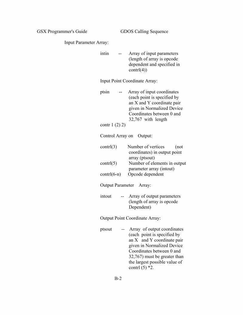
GSX Programmer's Guide GDOS Calling Sequence Input Parameter Array: intin -- Array of input parameters (length of array is opcode dependent and specified in contrl(4)) Input Point Coordinate Array: ptsin -- Array of input coordinates (each point is specified by an X and Y coordinate pair given in Normalized Device Coordinates between 0 and 32,767 with length contr 1 (2) 2) Control Array on Output: contrl(3) Number of vertices (not coordinates) in output point array (ptsout) contrl(5) Number of elements in output parameter array (intout) contrl(6-n) Opcode dependent Output Parameter Array: intout -- Array of output parameters (length of array is opcode Dependent) Output Point Coordinate Array: ptsout -- Array of output coordinates (each point is specified by an X and Y coordinate pair given in Normalized Device Coordinates between 0 and 32,767) must be greater than the largest possible value of contrl (5) *2. B-2

GSX Programmer's Guide GDOS Calling Sequence All array elements are type INTEGER (2 bytes) All arrays are 1-based; that is, the double- word address at PB points to the first element of the control array (contr 1 (1) ) . The meaning of the input and output parameter arrays is dependent on the opcode. See Appendix C, "Virtual Device Interface Specification," for details. GDOS preserves the BP (base pointer) and DS (data segment) registers. All other registers are subject to change when returned f rom GDOS. INVOKING DEVICE Device drivers are invoked with a Callf from DRIVERS GSX and should return with a Retf. The driver must switch to its own stack for internal use, except for an allowed overhead for a few pushes to save the caller 's context. The following entry procedure is recommended to provide an error free calling sequence: CGroup Group Driver-Code Driver-Code CSeg Public Driver Driver: Mov Ax,Sp Save caller's stack pointers Mov Bx,Ss ; Note that Mov Ss,xxx Mov Sp,xxx is not interruptible on 8086/8088. Mov Ss,StackBase ; Switch to driver's stack Mov Sp,Offset Top_Stack Push Bx ; Push caller's stack pointer Push Ax Push BP ; Save caller's frame Push Ds ; Save parameter pointer Push DX Pushf ; Save caller's direction flag B-3

GSX Programmer's Guide Invoking Device Drivers ; Invoke the driver. Ds:Dx points to the parameter block. ; It returns with a Retf. Callf Dd_Driver Invoke the driver with DS:DX popf Restore caller's direction flag Pop Dx Restore caller's Ds:Dx pop Ds Pop Bp Restore caller's stack frame Pop Ax Restore caller's Ss:Sp Pop Bx via Mov Ss,Bx Bx Mov Sp,Ax and Ax Retf StackBase Dw Seg --op-Stack Dd-Driver-Code CSeg Extrn Dd-Driver :Far Stack SSeg Rs 16 This module pushes 8 words Top-Stack is defined in the last module linked in. Extrn Top-Stack :Byte End After coding, assembling and linking your device driver, you have a CMD file if you use CP/M. First change the filetype to SYS using the CP/M RENAME command or a similar command for your operating system: A>REN GIOSXX.SYS=GIOSXX.CMD Then, to make this driver known to GSX, include its name in the Assignment Table. This table B-4

GSX Prograrnmer's Guide Error Messages is located in file ASSIGN.SYS and is simply a text file with a specific format containing the names of driver files and the logical device numbers or workstation IDs that you wish to associate with particular devices. Refer to Section 3, "GDOS," or Section 4, "GIOS," for details. ERROR MESSAGES In general, registers and flags (including the direction flag) are not restored upon returning f rom a call to GSX. The GIOS file will preserve the DS, SS and CS registers and BP and SP, but it is not required to preserve any others. GSX does not change any registers as returned from the GIOS except during an OPEN WORKSTATION command. In this case Ax is modified to return status information (the flags are also modified by this command). The meaning of the contents of Ax on returning from the OPEN WORKSTATION call is as follows: AL=O workstation opened successfully AL=255 error condition--Jevice driver riot loaded. In this case AH has a further meaning: AH 0 ASSIGN.SYS not found 1 Syntax error in ASSIGN.SYS 2 Device ID not found in ASSIGN.SYS 3 Close error on ASSIGN.SYS 4 Device driver file specified in ASSIGN.SYS not found 5 Device driver file specified in ASSIGN.SYS empty 6 Syntax error on file specified in ASSIGN.SYS (that is, absolute code segment or not CMD format) 7 Not enough room for file specified B-5

GSX Programmer's Guide Error Messages If a read error occurs during the transfer of a GIOS file when an OPEN WORKSTATION call is in progress, the application program is terminated, a message is displayed, and control is returned to the operating system user interface module. The following error messages can be displayed in response to GSX calls: GSX CS:IP GIOS load error on Id xxxxh (hex) An error occurred while transferring the device driver from disk. The value of the CS:IP and the device ID are also shown. GSX CS:IP GIOS invalid The currently loaded device driver is invalid. This error probably occurred after a load error when the application does not perform an OPEN WORKSTATION command as the first graphics operation. GSX CS:IP Illegal function: (Cx) An invalid function code (@0473h) was specified in Cx. The erroneous code is displayed. Refer to the GSX user's guide for your system for additional error messages output by GSX. End of Appendix B B-6

Appendix C VIRTUAL DEVICE INTERFACE (VDI) SPECIFICATION INTRODUCTION This appendix contains the specification of the Virtual Device Interface (VDI) . The VDI defines how device drivers interface to GDOS, the device-independent portion of GSX. The context for this document is from the DEVICE DRIVER point of view. All coordinate information is assumed to be in device coordinate space. FORMAT Function: GSX graphics operation Input Parameters contrl(l) Opcode for driver function. contrl(2) Number of vertices in array ptsin. Each vertex consists of an x and a y coordinate pair so the length of this array is twice as long as the number of vertices specified. contrl(4) Length of integer array intin. contrl(6-n) Opcode dependent information. intin Array of integer input parameters. ptsin Array of input point coordinate data. Output Parameters contrl(3) Number of vertices in array ptsout. Each vertex consists of an x and a y coordinate pair so the length of this array is twice as long as the number of vertices specified. Other data may be passed back here depending on the opcode. contrl(5) Length of integer array intout. contrl(6-n) Opcode dependent information. C-1

GSX Programmer's Guide Format intout Array of integer output point parameters. ptsout Array of output point coordinate data. Notes All data passed to the device driver is assumed to be 2-byte INTEGERS, including individual characters in character strings. All coordinates passed to GSX are in Normalized Device Coordinates (0-32767 along each axis). These units are then mapped to the actual device units (for example, rasters for CRTs or steps for plotters and printers) by GSX so that all coordinates passed to the device driver are in device units. Because both input and output coordinates are converted by GSX, both the calling routine and the device driver must make sure that the input vertex count (contrl(2)) and output vertex count (contrl(3)) are set. The calling routine must set contrl(2) to 0 if no x,y coordinates are are being passed to GSX. Similarly, the device driver must set contrl(3) to 0 if no x,y coordinates are being returned through GSX. Coordinates returned by GSX are assumed to be the bottom left edge of the pixel. As a consequence, points at the top and right edges of the device coordinate system will not be at the edge of the Normalized Device Coordinates (NDC) system. Exactly how far away they will be is device dependent. Because 0-32767 maps to the full extent on each axis, coordinate values are scaled differently on the x and y axes of devices that do not have a square display. C-2

GSX Programmer's Guide Format All references to arrays are 1-based; that is, subscripted element I is the first element in the array. On calls to the GDOS the number of arguments passed in the intin array (contrl (4) ) , and the maximum size of the intout array (contrl(5)) should be set by the application. On return to the GDOS by the GIOS the number of arguments in the intout array should be set by the GIOS. Refer to Appendixes A and B for GDOS calling conventions for specific operating systems. All opcodes must be recognized, whether or not they produce any action. If an opcode is out of range then no action is performed. A list of required opcodes for CRT devices, plotters, and printers follows the specification. These opcodes must be present and perform as specified. All opcodes should be implemented whenever possible since full implementation gives better quality graphics. Device driver I/O (that is, communication between the device driver and the device via the system hardware ports) is done through operating system calls. C-3

GSX Programmer's Guide Open Workstation OPEN WORKSTATION Initialize a graphic workstation. Input contrl(l) Opcode = I contrl(2) 0 contrl(4) Length of intin = 10 intin Initial defaults (for example, lifestyle color and character size) intin(l) Workstation identifier (device driver id). This value is used to determine which device driver to dynamically load into memory. intin(2) Linetype intin(3) Polyline color index intin(4) Marker type intin(5) Polymarker color index intin(6) Text font intin(7) Text color index intin(8) Fill interior style intin(9) Fill style index intin(IO) Fill color index Output contrl(3) Number of output vertices 6 contrl(5) Length of intout = 45 intout(l) Maximum addressable width of screen/plotter in rasters/ steps assuming a 0 start point (for example, a resolution of 640 implies an addressable area of 0-639, so intout(l)=639) intout (2) Maximum addressable height of screen/plotter in rasters/ steps assuming a 0 start point (for example, a resolution of 480 implies an addressable area of 0-479, so intout(2)=479) intout(3) Device Coordinate units flag 0 Device capab1e of producing precisely scaled image (typically plotters and printers) C-4

GSX Programmer's Guide Open Workstation 1 Device not capable of precisely scaled image (CRTS) intout(4) Width of one pixel (plotter step, or aspect ratio for CRT) in micrometers intout(5) Height of one pixel (plotter step, or aspect ratio for CRT) in micrometers intout(6) Number of character heights 0 = continuous scaling intout(7) Number of linetypes intout(3) Number of line widths intout(9) Number of marker types intout(IO) Number of marker sizes intout(Il) Number of fonts intout(12) Number of patterns intout(13) Number of hatch styles intout(14) Number of predef ined colors (must be at least 2 even for monochrome device). This is the number of colors that can be displayed on the device simultaneously. intout(15) Number of Generalized Drawing Primitives (GDPS) intout(16)- intout(25) Linear list of GDP numbers supported -1 no more GDPs in list. Application should search list until finding a -1 for the desired GDP. 1 bar 2 arc 3 pie slice 4 circle 5 ruling chars intout(26)- C-5
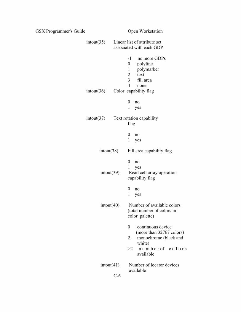
GSX Programmer's Guide Open Workstation intout(35) Linear list of attribute set associated with each GDP -1 no more GDPs 0 polyline 1 polymarker 2 text 3 fill area 4 none intout(36) Color capability flag 0 no 1 yes intout(37) Text rotation capability flag 0 no 1 yes intout(38) Fill area capability flag 0 no 1 yes intout(39) Read cell array operation capability flag 0 no 1 yes intout(40) Number of available colors (total number of colors in color palette) 0 continuous device (more than 32767 colors) 2. monochrome (black and white) >2 n u m b e r of c o I o r s available intout(41) Number of locator devices available C-6

GSX Programmer's Guide Open Workstation intout(42) Number of valuator devices available intout(43) Number of choice devices available intout(44) Number of string devices available intout(45) Workstation type 0 Output only 1 Input only 2 Input/Output 3 Device independent segment storage 4 GKS Metafile output Ptsout(l) 0 ptsout(2) Minimum character height in device units (not cell size) ptsout(3) 0 ptsout(4) Maximum character height in device units (not cell size) ptsout(5) Minimum line width in device units ptsout(6) 0 ptsout(7) Maximum line width in device units ptsout(8) 0 ptsout(9) 0 ptsout(10) Minimum marker height in device units (not cell size) ptsout(ll) 0 ptsout(12) Maximum marker height in device units (not cell size) The default color table should be set up differently for a monochrome and a color device. Monochrome CRT type devices C-7

GSX Programmer's Guide Open Workstation Index Color 0 Black 1 White Monochrome Printer/Plotter devices Index Color 0 White 1 Black Color Index Color 0 Black 1 Red 2 Green 3 Blue 4 Cyan 5 Yellow 6 Magenta 7 White 8-n White Other default values that should be set by the driver during initialization are as follows: Character height = Minimum character height Character up vector = 90 degrees counterclockwise from the right horizontal (O degrees rotation) Line width = 1 device unit (raster, plotter step) marker height = Minimum marker height Writing mode = Replace Input mode = Request for all input classes (locator, valuator, choice, string) C-8

GSX Programmer's Guide Close Workstation Description The Open Workstation operation causes a graphics device to become the current device for the application program. The device is initialized with the parameters in the input array and information about the device is returned to GDOS. The graphic device is selected, and, if it is a CRT, the screen is cleared and the alpha device is deselected and blanked. CLOSE WORKSTATION Stop all graphics output to this workstation. Input contrl(l) opcode = 2 contrl(2) 0 Output contrl(3) 0 Description The Close Workstation operation terminates the graphics device properly and prevents any further output to the device. If the device is a CRT, the alpha device is selected, the screen is cleared , and the graphics device is deselected and blanked. If the device is a printer, then an update is executed. CLEAR WORKSTATION Clear CRT screen or prompt for new paper on plotter. Input contrl(l) Opcode = 3 contrl(2) 0 Output contrl(3) 0 Description The Clear Workstation operation causes CRT screens to be erased. If the device is a plotter without paper advance, the operator is prompted to load a new page. If the device is a printer a form feed is issued and then an update is executed. C-9

GSX Programmer's Guide Update Workstation UPDATE WORKSTATION Display all pending graphics on workstation. Input contrl(l) Opcode = 4 contrl(2) 0 Output contrl(3) 0 Description The Update Workstation operation causes all pending graphics commands that are queued to be executed immediately. The operation is analogous to flushing buffers. For printer drivers this call must be used to start output to the printer. ESCAPE Perform device specific operation. Input contrl(l) Opcode = 5 contrl(2) Number of input vertices contrl(4) Number of input parameters contrl(6) Function identifier 1 = INQUIRE ADDRESSABLE CHARACTER CELLS 2 = ENTER GRAPHICS MODE 3 = EXIT GRAPHICS MODE 4 = CURSOR UP 5 = CURSOR DOWN 6 = CURSOR RIGHT 7 = CURSOR LEFT 8 = HOME CURSOR 9 = ERASE TO END OF SCREEN 10 = ERASE TO END OF LINE 11 = DIRECT CURSOR ADDRESS 12 = OUTPUT CURSOR ADDRESSABLE TEXT 13 = REVERSE VIDEO ON 14 = REVERSE VIDEO OFF 15 = INQUIRE CURRENT CURSOR ADDRESS 16 = INQUIRE TABLET STATUS 17 = HARDCOPY 18 = PLACE GRAPHIC CURSOR AT LOCATION C-10

GSX Proqrammer's Guide Escape 19 = REMOVE LAST GRAPHIC CURSOR 20-50 = UNUSED BUT RESERVED FOR FUTURE EXPANSION 51-100 = UNUSED AND AVAILABLE FOR USE intin Function dependent information (described on following pages) ptsin Array of input coordinates for escape function Output contrl(3) Number of output vertices contrl(5) Number of output parameters intout Array of output parameters ptsout Array of output coordinates Description The Escape operation allows the special capabilities of a graphics device to be accessed from the application program. Some escape functions above are predefined, but others can be defined for your particular devices. The parameters passed are dependent on the function being performed. C-11

GSX Programmer's Guide Escape ESCAPE: INQUIRE Return the number of alpha cursor addressable ADDRESSABLE columns and alpha cursor addressable rows. CHARACTER CELLS Input contrl(2) 0 contrl(6) Function ID = I Output contr 1 (3) 0 intout(l) Number of addressable rows on the screen, typically 24 (-l indicates cursor addressing not possible) intout(2) Number of addressable columns on the screen, typically 80 (-l indicates cursor addressing not possible) Description This operation returns information to the calling program about the number of vertical (rows) andhorizontal (columns) positionswhere the alpha cursor can be positioned on the screen. C-12
GSX Programmer's Guide Escape ESCAPE: ENTER Enter graphics mode if different from alpha GRAPHICS MODE mode. Input contrl(2) 0 contrl(6) Function id = 2 Output contrl(3) 0 Description This operation causes the graphics device to enter the graphics mode if different than the alpha mode. Used to explicitly exit alpha cursor addressing mode and to transition from alpha to graphic mode properly. The graphics device is selected and cleared. The alpha device is deselected and blanked. ESCAPE: EXIT Exit graphics mode if different from alpha GRAPHICS MODE mode. Input contrl(2) 0 contrl(6) Function id = 3 Output contrl(3) 0 Description The Exit Graphics operation causes the graphics device to exit the graphics mode if different than the alpha mode. used to explicitly enter the alpha cursor addressing mode and to transition from graphics to alpha mode properly. The alpha device is selected and cleared. The graphics device is deselected and blanked. C-13

GSX Programmer's Guide Escape ESCAPE: CURSOR UP Move alpha cursor up one row without altering horizontal position. Input contrl(2) 0 contrl(6) Function id = 4 Output contrl(3) 0 Description This operation moves the alpha cursor up one row without altering the horizontal position. Tf the cursor is already at the top margin, no action results. ESCAPE: CURSOR Move alpha cursor down one row without DOWN altering horizontal position. Input contrl(2) 0 contrl(6) Function id = 5 Output contrl(3) 0 Description This operation moves the alpha cursor down one row without altering the horizontal position. If the cursor is already at the bottom margin, no action results. C-14

GSX Programmer's Guide Escape ESCAPE: CURSOR Move alpha cursor right one column without RIGHT altering vertical position. Input contrl(2) 0 contrl(6) Function id = 6 Output contrl(3) 0 Description The Cursor Right operation moves the alpha cursor right one column without altering the vertical position. If the cursor is already at the right margin, no action results ESCAPE: CURSOR Move alpha cursor left one column without LEFT altering vertical position. Input contrl(2) 0 contrl(6) Function id = 7 Output contrl(3) 0 Description The Cursor Left operation causes the alpha cursor to move one column to the left without altering the vertical position. If the cursor is already at the left margin, no action results. C-15

GSX Programmer's Guide Escape ESCAPE: HOME Send cursor to home position. CURSOR Input contrl(2) 0 contrl(6) Function id = 8 Output contrl(3) 0 Description This operation causes the alpha cursor to move to the home position, usually the upper left corner of a CRT display. ESCAPE: ERASE TO Erase from current alpha cursor position to END OF SCREEN the end of the screen. Input contrl(2) 0 contrl(6) Function id = 9 Output contrl(3) 0 Description This operation erases the display surface from the current alpha cursor position to the end of the screen. The current alpha cursor location does not change. C-16

GSX Programmer's Guide Escape ESCAPE: ERASE TO Erase from the current alpha cursor position END OF LINE to the end of the line. Input contrl(2) 0 contrl(6) Function id = 10 Output contrl(3) 0 Description This operation erases the display surface from the current alpha cursor position to the end of the current line. The current alpha cursor location does not change. ESCAPE: DIRECT Move alpha cursor to specified row and CURSOR ADDRESS column. Input contrl(2) 0 contrl(6) Function id = 11 intin(l) Row number (I - number of rows) intin(2) Column number (I - number of columns) Output contrl(3) 0 Description The Direct Cursor Address operation moves the alpha cursor directly to the specified row and column address anywhere on the display surface. Addresses that are beyond the range that can be displayed on the screen are set to the maximum row and/or column accordingly. C-17

GSX Programmer's Guide Escape ESCAPE: OUTPUT Output text at the current alpha cursor CURSOR ADDRESSABLE position. TEXT Input contrl(2) 0 contrl (4) Number of characters i n character string contrl(6) Function id = 12 intin Text string in ASCII Output contrl(3) 0 Description This operation displays a string of text starting at the current cursor position. Alpha text characteristics are determined by the attributes currently in effect (for example, reverse video). C-18

GSX Programmer's Guide Escape ESCAPE: REVERSE Display subsequent cursor addressable text in VIDEO ON reverse video. Input contrl(2) 0 contrl(6) Function id 13 Output contrl(3) 0 Description This operation causes all subsequent text to be displayed in reverse video format; that is, characters are dark on a light background. ESCAPE: REVERSE Display subsequent cursor addressable text in VIDEO OFF standard video. Input contrl(2) 0 contrl(6) Function id = 14 Output contrl(3) 0 Description This operation causes all subsequent text to be displayed in normal video format; that is, characters are light on a dark background. C-19

GSX Programmer's Guide Escape ESCAPE: INQUIRE Return the current cursor position. CURRENT CURSOR ADDRESS Input contrl(2) 0 contrl(6) Function id = 15 Output contrl(3) 0 intout(l) Row number (1 - number of rows) intout(2) Column number (1 - number of columns Description This operation returns the current position of the alpha cursor in row, column coordinates. ESCAPE: INQUIRE Return tablet status. TABLET STATUS Input contrl(2) 0 contrl(6) Function id = 16 Output contrl(3) 0 intout(l) tablet status 0 = tablet not available 1 = tablet available Description This operation returns tablet status whether a graphics tablet, mouse, joystick, or other similar devices are connected to the workstation. C-20

GSX Programiner's Guide Escape ESCAPE: HARD COPY Generate hardcopy. Input contrl(2) 0 contrl(6) Function id = 17 Output contrl(3) 0 Description This operation causes the device to generate a hardcopy. This function is very device specific and can entail copying the screen to a printer or other attached hardcopy device. ESCAPE: PLACE Place a graphic cursor at specified location GRAPHIC CURSOR AT LOCATION Input contrl(2) 2 contrl(6) Function id = 18 ptsin(l) x-coordinate of location to place cursor ptsin(2) y-coordinate of location to place cursor Output contrl(3) 0 Description Place Graphic Cursor at the specified location. This is device dependent and can be an underbar, block, or similar character. This cursor should be the same type as used for request mode locator input. In this way, if sample mode input is supported, the application may use this call to generate the cursor for rubber band type d-awing. In memory mapped devices, it is drawn in XOR mode so that it can be removed. The cursor has no attributes; for example, style or color index. C-21

GSX Programmer's Guide Escape ESCAPE: REMOVE Remove last graphic cursor/marker. LAST GRAPHIC CURSOR Input contrl(2) 0 contrl(6) Function id = 19 Output contrl(3) 0 Description This operation removes the last graphic cursor placed on the screen. C-22
GSX Programmer's Guide Polyline POLYLINE Output a polyline to device. Input contrl(l) opcode = 6 contrl(2) Number of vertices (x,y pairs) in polyline (n), ptsin Array of coordinates of polyline in device units (for example, rasters and plotter steps) ptsin(l) x-coordinate of first point ptsin (2) y-coordinate of first point ptsin (3) x-coordinate of second point ptsin(4) y-coordinate of second point ptsin(2n-1) x-coordinate of last point ptsin(2n) y-coordinate of last point Output contrl(3) 0 Description This operation causes a polyline to be displayed on the graphics device. The starting point for the polyline is the first point in the input array .Lines are drawn between subsequent points in the array. Make sure that the lines exhibit the current line attributes: color, linetype, line width. 0 length lines should be displayed. A single coordinate pair should not be displayed. C-23

GSX Programmers' Guide Polymaker POLYMARKER Output markers to the device. Input contrl(l) Opcode = 7 contrl(2) Number of markers ptsin Array of coordinates in (device units (n) (for example, rasters and plotter steps) ptsin(l) x-coordinate of first marker ptsin(2) y-coordinate of first marker ptsin(3) x-coordinate of second marker ptsin(4) y-coorclinate of second marker ptsin(2n-1) x-coordinate of last marker ptsin(2n) y-coordinate of last marker Output contrl(3) 0 Description This operation causes markers to be drawn at the points specified in the input array. Make sure the markers display the current attributes: color, scale, and type. C-24

GSX Programmer's Guide Text TEXT Write text at specified position. Input contrl(l) Opcode = 8 contrl(2) Number of vertices = 1 contrl(4) Number of characters in text string intin Word character string in ASCII ptsin(l) x-coordinate of start point of text in device units ptsin(2) y-coordinate of start point of text in device units Output contrl(3) 0 Description This operation writes text to the display surface starting at the position specified by the input parameters. Note that the X,Y position specified is the lower left corner of the character itself, not the character cell. Also, make sure the text exhibits current text attributes: color, height, character up vector, font. Each word of the intin array contains only one character. Any character code out of range for the selected font should be mapped to a blank. C-25

GSX Programmers' Guide Filled Area FILLED AREA Fill a polygon. Input contrl(l) Opcode = 9 contrl(2) Number of vertices in polygon (n) ptsin Array of coordinates of polygon in device units ptsin(l) x-coordinate of first point ptsin(2) y-coordinate of first point ptsin(3) x-coordinate of second point ptsin(4) y-coordinate of second point ptsin(2n-1) x-coordinate of last point ptsin(2n) y-coordinate of last point Output contrl(3) 0 Description This operation fills a polygon specified by the input array with the current fill color. Ensure the correct color, fill interior style (hollow, solid, pattern or hatch) and fill style index are in effect before doing the fill. If the device cannot do area fill, it must at least outline the polygon in the current fill color. The device driver must ensure that the fill area is closed by connecting the first point to the last point. A polygon with zero area should be displayed as a dot. A polygon with only one endpoint should not be displayed. C-26
GSX Programmer's Guide Cell Array CELL ARRAY Display cell array. Input contrl(l) opcode = 10 contrl(2) 2 contrl(4) Length of color index array contrl(6) Length of each row in color index array (size as declared in a high level language) contrl (7) Number of elements used in each row of color index array contrl(B) Number of rows in color index array contrl(9) Pixel operation to be performed 1 replace 2 overstrike 3 complement (xor) 4 erase intin(l) Color index array (stored one row at time) ptsin(l) x-coordinate of lower left corner in device units ptsin(2) y-coordinate of lower left corner in device units ptsin(3) x-coordinate of upper right corner in device units ptsin(4) y-coordinate of upper right corner in device units Output contrl(3) 0 Description The Cell Array operation causes the device to draw a rectangular array which is defined by the input parameter X,Y coordinates and the color index array. C-27
GSX Programmer's Guide Cell Array The extents of the cell are defined by the lower left-hand and the upper right-hand X,Y coordinates. Within the rectangle defined by those points, the color index array specifies colors for individual components of the cell. Each row of the color index array should be expanded to fill the entire width of the rectangle specified if necessary, via pixel replication. Each row of the color index array should also be replicated the appropriate number of times to fill the entire height of the rectangular area. If the device cannot do cell arrays it must at least outline the area in the current line color. C-28

GSX Programmer's Guide Generalized Drawing Primitive GENERALLIZED Output a primitive display element. DRAWING PRIMITIVE (GDP) Input contrl(l) Opcode = 11 contrl(2) Number of vertices in ptsin contrl(4) Length of input array intin contrl(6) Primitive id 1 -- BAR -- uses f ill area attributes (interior style , f ill style, f ill color) 2 -- ARC uses n e attributes (c o o r linetype, width) 3 -- PIE SLICE -- uses fill area attributes (interior style, fill style, fill color) 4 -- CIRCLE -- uses f ill area attributes (interior sty1e , f ill style, fill color) 5 -- PRINT GRAPHIC CHARACTERS (RULING CHARACTERS) 6 -- 7 are unused but reserved for future expansion 8 -- 1 0 are unused and available for use ptsin -- Array of coordinates for GDP ptsin(l) -- x-coordinate of first point ptsin(2) -- y-coordinate of first point C-29

GSX Programmer's Guide Generalized Drawing Primitive ptsin(3) -- x-coordinate of second point ptsin(4) -- y-coordinate of second point ptsin(2n-1) -- x-coordinate of last point ptsin(2n) -- y-coordinate of last point intin Data record BAR contrl(2) 2 (number of vertices contrl(6) 1 (primitive ID) ptsin(l) x-coordinate of lower left-hand corner of bar ptsin(2) y-coordinate of lower left-hand corner of bar ptsin(3) x-coordinate of upper right- hand corner of bar ptsin(4) y-coordinate of upperright-hand corner of bar ARC AND PIE SLICE contrl(2) 4 ( number of vertices) contrl(6) 2 (ARC) or 3 (PIE SLICE) intin(l) Start angle in tenths of degrees (0- 360 0) intin (2) End angle in tenths of degrees (0- 360 0) C-30

GSX Programmer's Guide Generalized Drawing Primitive ptsin(l) x-coordinate of center point of arc ptsin(2) y-coordinate of center point of arc ptsin(3) x-coordinate of start point of arc on circumference ptsin(4) y-coordinate of start point of arc on circumference ptsin(5) x-coordinate of end point of arc on circumference ptsin(6) y-coordinate of end point of arc on circumference ptsin(7) Radius ptsin(3) 0 CIRCLE contrl(2) 3 number of points) contrl(6) 4 (primitive id) ptsin(l) x-coordinate of center point of circle ptsin(2) y-coordinate of center point of circle ptsin(3) x-coordinate of point on circumference ptsin(4) y-coordinate of point on circumference ptsin(5) Radius ptsin(6) 0 C-31

GSX Programmer's Guide Generalized Drawing Primitive PRINT GRAPHIC CHARACTERS For graphics on printer (such as Diablo and Epson) contrl(2) 1 (number of points) contrl(4) Number of characters to output contrl(6) 5 intin Graphic characters to output ptsin(l) x-coordinate of start point of characters ptsin(2) y-coordinate of start point of characters Output contrl(3) 0 Description The Generalized Drawing Primitive (GDP) operation allows you to take advantage of the intrinsic drawing capabilities of your graphics device. Special elements such as arcs and circles can be accessed through this mechanism. Several primitive identifiers are predefined and others are available for expansion. The control and data arrays are dependent on the nature of the primitive. In some GDPs (Arc, Circle, Pie slice) redundant but consistent information is provided. Only the necessary information for a particular device need be used. Also, all angle specif ications assume that 0 degrees is 90 degrees to the right of vertical, with values increasing in the counterclockwise direction. C-32

GSX Programmer's Guide Set Character Height SET CHARACTER Set character height. HEIGHT Input contrl(l) Opcode = 12 contrl(2) Number of vertices = 1 ptsin(l) 0 ptsin(2) Requested character height in device units (rasters, plotter steps) Output contrl(3) Number of vertices = 2 ptsout(l) Actual character width selected in device units ptsout(2) Actual character height selected in device units ptsout(3) Character cell width in device units ptsout(4) Character cell height in device units Description This operation sets the current text character height in Device Units. The specified height is the height of the character itself rather than the character cell. The driver returns the size of both the character and the character cell. The character size is defined as the size of an uppercase W. If the requested size does not exist, a smaller size should be used. 10000010 10000010 10000010 10010010 CHARACTER HEIGHT CELL HEIGHT 10101010 11000110 ORIGIN OF ROTATION 10000010 BASE LINE 00000000 C-33

GSX Programmer's Guide Set Character Up Vector 10000010 ------------------------------------ 10000010 | | 10000010 | | 10010010 |-CHARACTER HEIGHT |- CELL HEIGHT 10101010 | | 11000110 | | ORIGIN OF ROTATION 10000010 --| <-BASE LINE | 00000000 ------------------------------------ SET CHARACTER UP Set text direction. VECTOR Input contrl(l) opcode = 13 contrl(2) 0 intin(l) Requested angle of rotation of character baseline (in tenths of degrees 0 - 3600) intin(2) Run of angle cos (angle) * 100 (0-100) intin(3) Rise of angle sin (angle) * 100 (0-100) Output contrl(3) 0 contrl(5) 1 intout(l) Angle of rotation of character baseline selected (in tenths of degrees 0-3600) Description This operation requests an angle of rotation specif ied in tenths of degrees for the CHARACTER UP VECTOR, which specifies the baseline for subsequent text. The driver returns the actual up direction that is a best fit match to the requested value. For convenience, redundant but consistent information is provided on input. Only information pertinent to a given device need be used. The angle specification assumes that 0 degrees is 90 degrees to the right of vertical C-34

GSX Programmer's Guide Set Color Representation (east on a compass), with angles increasing in the counterclockwise direction. 90 | 180 ------- 0 | 270 SET COLOR Specify color index value. REPRESENTATION Input contrl(l) opcode = 14 contrl(2) 0 intin(l) Color index intin(2) Red color intensity (in tenths of percent 0- 1000) intin(3) Green color intensity intin(4) Blue color intensity Output contrl(3) 0 Description This operation associates a color index with the color specified in RGB units. At least two color indexes are required (black and white for monochrome). On a monochrome device, any percentage of color should be mapped to white. On color devices without palettes, a simple remapping of the color indexes is sufficient. On color devices with palettes, loading the palette map is the proper operation. If the color index requested is out of range, no operation is performed. C-35

GSX Programmer's Guide Set Polyline Linetype SET POLYLINE Set polyline linetype. LINETYPE Input contrl(l) Opcode = 15 contrl(2) 0 intin(l) Requested linestyle Output contrl(3) 0 intout(l) Linestyle selected Description This operation sets the linetype for subsequent polyline operations. The total number of linestyles available is device dependent; however, 5 linestyles are required: one solid plus four dash styles. If the requested linestyle is out of range, use linestyle 1 (solid). STYLE 1 SOLID 1111111111111111 STYLE 2 DASH 1111111000000000 STYLE 3 DOT 1110000011100000 STYLE 4 DASH,DOT 1111111000111000 STYLE 5 LONG DASH 111111111110000 C-36

GSX Programmer's Guide Set Polyline Line Width SET POLYLINE Set polyline line width. LINE WIDTH Input contrl(l) opcode = 16 contrl(2) Number of input vertices = 1 ptsin(l) Requested line width in device units ptsin(2) 0 Output contrl(3) Number of output vertices = 1 ptsout(l) Selected line width in device units ptsout(2) 0 Description This operation sets the width of lines for subsequent polyline operations. Any attempt to set the width beyond the specified maximum will set it to the maximum line width. SET POLYLINE Set polyline color index. COLOR INDEX Input contrl(l) opcode = 17 contrl(2) 0 intin(l) Requested color index Output contrl(3) 0 intout(l) Color index selected Description This operation sets the color index for subsequent polyline operations. The color signified by the index is determined by the SET-COLOR- REPRESENTATION operation. At least two color indexes are required. Color indexes range from 0 to a device-dependent maximum. If the selected index is out of range, use the MAXIMUM color index. C-37

GSX Programmer's Guide Set Polymarker Type SET POLYMARKER Set polymarker type. TYPE Input contrl(l) Opcode = 18 contrl(2) 0 intin(l) Requested polymarker type Output contrl(3) 0 intout(l) Polymarker type selected Description This operation sets the marker type for subsequent polymarker operations. The total number of markers available is device- dependent; however, five marker types are required, as follows: 1 - . Dot 2 - + Plus 3 - * Asterisk 4 - 0 Circle 5 - X Diagonal Cross If the requested marker type is out of range, use type 3. Marker 1 should always be implemented as the smallest dot that can be displayed. C-38
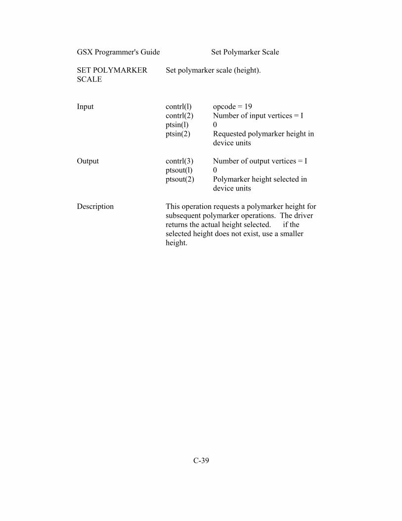
GSX Programmer's Guide Set Polymarker Scale SET POLYMARKER Set polymarker scale (height). SCALE Input contrl(l) opcode = 19 contrl(2) Number of input vertices = I ptsin(l) 0 ptsin(2) Requested polymarker height in device units Output contrl(3) Number of output vertices = I ptsout(l) 0 ptsout(2) Polymarker height selected in device units Description This operation requests a polymarker height for subsequent polymarker operations. The driver returns the actual height selected. if the selected height does not exist, use a smaller height. C-39

GSX Programmer's Guide Set Polymarker Color Index SET POLYMARKER Set polymarker color index. COLOR INDEX Input contrl(l) Opcode 20 contrl(2) 0 intin(l) Requested polymarker color index Output contrl(3) 0 intout(l) Polymarker color index selected Description This operation sets the color index for subsequent polymarker operations. The value of the index is specified by the COLOR operation. At least two color indexes are required. If the index is out of range, use the MAXIMUM color index. C-40

GSX Programmer's Guide Set Text Font SET TEXT PONT Set the hardware text font. Input contrl(l) Opcode = 21 contrl(2) 0 intin(l) Requested hardware text font number Output contrl(3) 0 intout(l) Hardware text font selected Description This operation selects a character font for subsequent text operations. Fonts are device- dependent and are specified from I to a device- dependent maximum. C-41

GSX Programmer's Guide Set Text Color Index SET TEXT Set color index. COLOR INDEX Input contrl(l) Opcode = 22 contrl(2) 0 intin(l) Requested text color index Output contrl(3) 0 intout(l) Text color index selected Description This operation sets the color index for subsequent text operations. At least two color indexes are required. Color indexes range from 0 to a device-dependent maximum. If the selected index is out of range, use the MAXIMUM index. C-42

GSX Programmer's Guide Set Fill Interior Style SET FILL Set interior fill style. INTERIOR STYLE Input contrl(l) opcode = 23 contrl(2) 0 intin(l) Requested fill interior style 0 - Hollow (outline no fill) 1 - Solid 2 - Halftone pattern 3 - Hatch Output contrl(3) 0 intout(l) Fill interior style selected Description This operation sets the fill interior style to be used in subsequent polygon fill operations. If the requested style is not available, use Hollow. The style actually used is returned to the calling program. C-43
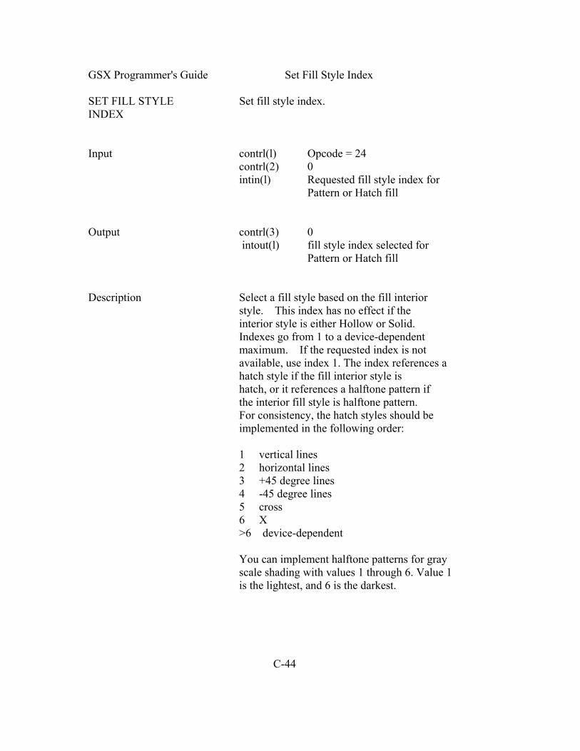
GSX Programmer's Guide Set Fill Style Index SET FILL STYLE Set fill style index. INDEX Input contrl(l) Opcode = 24 contrl(2) 0 intin(l) Requested fill style index for Pattern or Hatch fill Output contrl(3) 0 intout(l) fill style index selected for Pattern or Hatch fill Description Select a fill style based on the fill interior style. This index has no effect if the interior style is either Hollow or Solid. Indexes go from 1 to a device-dependent maximum. If the requested index is not available, use index 1. The index references a hatch style if the fill interior style is hatch, or it references a halftone pattern if the interior fill style is halftone pattern. For consistency, the hatch styles should be implemented in the following order: 1 vertical lines 2 horizontal lines 3 +45 degree lines 4 -45 degree lines 5 cross 6 X >6 device-dependent You can implement halftone patterns for gray scale shading with values 1 through 6. Value 1 is the lightest, and 6 is the darkest. C-44
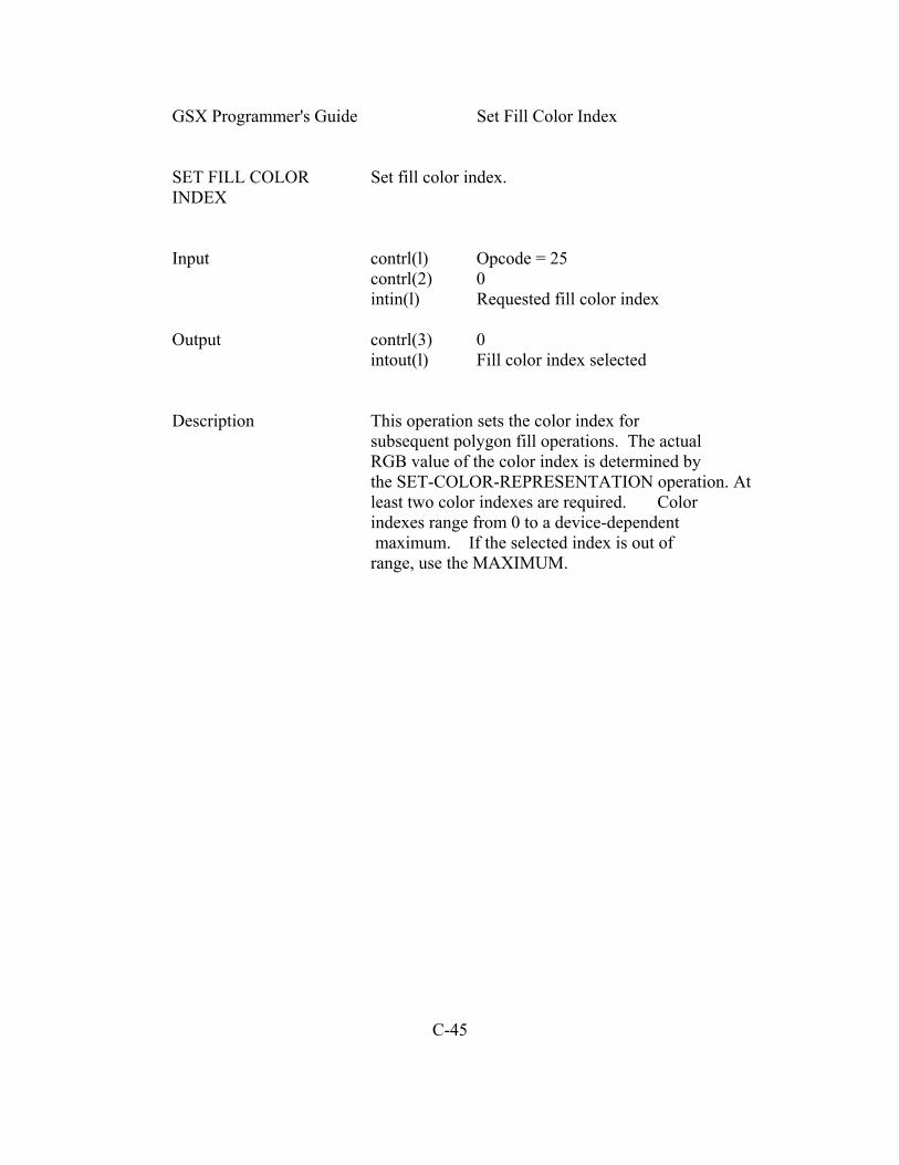
GSX Programmer's Guide Set Fill Color Index SET FILL COLOR Set fill color index. INDEX Input contrl(l) Opcode = 25 contrl(2) 0 intin(l) Requested fill color index Output contrl(3) 0 intout(l) Fill color index selected Description This operation sets the color index for subsequent polygon fill operations. The actual RGB value of the color index is determined by the SET-COLOR-REPRESENTATION operation. At least two color indexes are required. Color indexes range from 0 to a device-dependent maximum. If the selected index is out of range, use the MAXIMUM. C-45

GSX Programmer's Guide Inquire Color Representation INQUIRE COLOR Return color representation. REPRESENTATION Input contrl(l) Opcode = 26 contrl(2) 0 intin(l) Requested color index intin(2) Set or realized flag 0 = set (return color values requested) 1 = realized (return color values realized on device) Output contrl(3) 0 intout(l) Color index intout(2) Red intensity (in tenths of percent 0-1000) intout(3) Green intensity intout(4) Blue intensity Description This operation returns the requested or the actual value of the specified color index in RGB units. Note: The device driver must maintain tables of the color values that were set (requested) and the color values that were realized. On devices that have a continuous color range, one of these tables may not be necessary. If the selected index is out of range, use the values for the MAXIMUM color index. C-46

GSX Programmer's Guide Inquire Cell Array INQUIRE CELL Return cell array definition. Input contrl(l) opcode = 27 contrl(2) 2 contrl(4) Length of color index array contrl (6) Length of each row in color index array contrl(7) Number of rows in color index array ptsin(l) x-coordinate of lower 1eft corner in device units ptsin(2) y-coordinate of lower left corner in device units ptsin(3) x-coordinate of upper right corner in device units ptsin(4) y-coordinate of upper right corner in device units Output contrl(3) 0 contrl(8) Number of elements used in each row of color index array contrl(9) Number of rows used in color index array contrl(10) Invalid value flag 0 If no errors 1 If a color value could not be determined for some pixel intout Color index array (stored one row at time) -1 Indicates that a color index could not be determined for that particular pixel Description This operation returns the cell array def inition of the specif ied cell. Color indexes are returned one row at a time, starting from the top of the rectangular area, proceeding downward. C-47
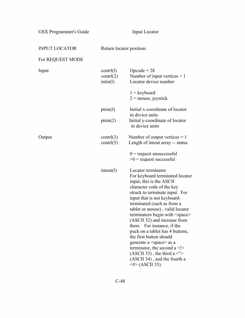
GSX Programmer's Guide Input Locator INPUT LOCATOR Return locator position. For REQUEST MODE Input contrl(l) Opcode = 28 contrl(2) Number of input vertices = 1 intin(l) Locator device number 1 = keyboard 2 = mouse, joystick ptsin(l) Initial x-coordinate of locator in device units ptsin(2) Initial y-coordinate of locator in device units Output contrl(3) Number of output vertices = 1 contrl(5) Length of intout array -- status 0 = request unsuccessful >0 = request successful intout(l) Locator terminator For keyboard terminated locator input, this is the ASCII character code of the key struck to terminate input. For input that is not keyboard- terminated (such as from a tablet or mouse) , valid locator terminators begin with <space> (ASCII 32) and increase from there. For instance, if the puck on a tablet has 4 buttons, the first button should generate a <space> as a terminator, the second a <!> (ASCII 33) , the third a <"> (ASCII 34) , and the fourth a <#> (ASCII 35). C-48

GSX Programmer's Guide Input Locator ptsout(l) Final x-coordinate of locator in device units ptsout(2) Final y-coordinate of locator in device units Description for This operation returns the position in Device Request Mode Coordinates of the specified locator device. Upon entry to the locator routine, a GRAPHIC cursor is placed at the initial coordinate. The GRAPHIC cursor is tracked with the input device until a terminating even occurs, which can result from the user pressing a key, or a button on a mouse. The cursor is removed when the terminating event occurs. For SAMPLE MODE Input contrl(l) Opcode @ 28 contrl(2) Number of input vertices = I intin(l) Locator device number 1 = keyboard 2 = mouse, joystick Output Table C-1. Sample Mode Status Returned Event Control Array (3) (5) Coordinates Change 1 0 Key Pressed; Coordinates Not Changed 0 1 No Input 0 1 Output contrl(3) Number of output vertices 1 = coordinate changed 0 = no coordinate changed C-49

GSX Programmer's Guide input Locator contrl(5) Length of intout array 0 = no terminating character 1 = terminating character returned intout(l) Locator t e r m i n a t o ri f terminating event occurs. For keyboard terminated locator input, this is the ASCII character code of the key struck to terminate input in the low byte and 0 in the high byte. For input that is not keyboard-terminated (such as from a tablet or mouse), valid locator terminators begin with 20 hex (ASCII 32) and increase from there. ptsout Returned if coordinate changed ptsout(l) New x-coordinate of locator in device units ptsout(2) New y-coordinate of locator in device units Description for Upon entry to the locator routine, NO cursor Sample Mode is displayed. input is sampled. if the coordinate changed, it is returned and contrl(3) is set to 1. Contrl(5) is set to 0. If a terminating event occurs, a character is returned and contrl(5) is set to 1. Contrl(3) is set to 0. if nothing happens, neither a character nor coordinate is returned. C-50

GSX Programmeris Guide Input Valuator INPUT VALUATOR Return value of valuator device. For REQUEST MODE Input contrl(l) opcode = 29 contrl(2) 0 intin(2) Initial value Output contrl(3) 0 contrl(5) 1 length of intout array intout(l) Output value intout(2) Terminator The terminating character is returned as an ASCII character for keyboard input with the high byte set to 0. Description for This operation returns the current value of Request Mode the valuator device. The initial value of the valuator is incremented or decremented (typically with the Up Arrow and Down Arrow keys) until a terminating character is struck. Typical implementation of the Up Arrow and Down Arrow keys is as follows: Pressing the Up Arrow key adds 10 to the valuator. o Pressing the Down Arrow key subtracts 10 from the valuator. However, when the Up and Down arrow keys are pressed with the Shift key, the following occurs: Up Arrow key adds I to the valuator. Down Arrow key subtracts 1 from the valuator. C-51

GSX Programmer's Guide Input Valuator For SAMPLE MODE Input contrl(l) opcode = 29 contrl(2) 0 Output contrl(3) 0 contrl(5) Length of intout array status 0 = nothing happened 1 = valuator changed 2 = terminating character intout(l) New valuator value intout(2) Terminator if terminating event occurred Description for This operation returns the current value of Sample Mode the valuator device. The valuator device is sampled. If the valuator changed, the valuator vaIue is incremented or decremented as required. If a terminating event occurred, the value is returned. If nothing happens, no value is returned. C-52

GSX Programmer's Guide Input Choice INPUT CHOICE Return choice device status keys. For REQUEST MODE Input contrl(l) opcode = 30 contrl(2) 0 intin(l) Choice device number 1 = function keys >1 = workstation-dependent Output contrl(3) 0 contrl(5) 1 intout(l) Choice number (range of valid numbers beginning at 1 to workstation-dependent maximum) Description for This operation returns the choice from the Request Mode selected choice device. Upon entry to the routine, the keys are sampled until a valid choice key is pressed. This choice is returned. The range for choice numbers begins at 1; its maximum value is device-dependent. Input Choice is typically implemented as function keys. For SAMPLE MODE Input contrl(l) opcode = 30 contrl(2) 0 intin(l) Choice device number 1 = function keys >1 = workstation-dependent Output contrl(3) 0 contrl(5) Choice status 0 = nothing happened 1 = sample successful 2 = nonchoice key

C-53 GSX Programmer's Guide Input Choice intout(l) Choice number if samp1e successful intout(2) Choice terminator if terminating event occurs Description for This operation returns the choice status of Sample Mode the selected choice device. Upon entry to the routine, input is sampled. If input is available and it is a valid choice key, it is returned. If input is available but it is not f rom a choice key, it is returned as a terminating event. The range of choice numbers begins at 1; its maximum value is device- dependent. C-54

GSX Programmer 's Guide Input String INPUT STRING Return string from specified string device. For REQUEST MODE Input contrl(l) Opcode = 31 contrl(2) 0 if nonecho mode 1 if echo mode intin(l) String device number 1 = default string device (keyboard) intin(2) Maximum string length intin(3) Echo mode 0 = do not echo input characters 1 = echo input characters ptsin(l) x coordinate of echo area in echo mode ptsin(2) y coordinate of echo area in echo mode Output contrl(3) 0 contrl(5) 1 0 = request unsuccessful >0 = request successful intout Output string Description for This operation returns a string from the Request Mode specified device. Upon entry input is accumulated until a carriage return is encountered or the intout array is full. if echo mode is enabled, text should be echoed to the screen with the current text attributes: color, height, character up vector, and font. C-55
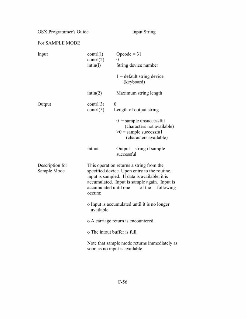
GSX Programmer's Guide Input String For SAMPLE MODE Input contrl(l) Opcode = 31 contrl(2) 0 intin(l) String device number 1 = default string device (keyboard) intin(2) Maximum string length Output contrl(3) 0 contrl(5) Length of output string 0 = sample unsuccessful (characters not available) >0 = sample successfu1 (characters available) intout Output string if sampIe successful Description for This operation returns a string from the Sample Mode specified device. Upon entry to the routine, input is sampled. If data is available, it is accumulated. Input is sample again. Input is accumulated until one of the following occurs: o Input is accumulated until it is no longer available o A carriage return is encountered. o The intout buffer is full. Note that sample mode returns immediately as soon as no input is available. C-56

GSX Programmer's Guide Set Writing Mode SET WRITING MODE Set writing mode Input contrl(l) Opcode = 32 contrl(2) 0 intin(l) Writing mode 1 = replace 2 = transparent 3 = XOR (complement) 4 = erase Output contrl(3) 0 intout Writing mode selected Description This operation affects the way pixels from lines, filled areas, and text are placed on the display. The following are descriptions of the four writing modes used by the GSX: o MASK is the line style mask. o FORE is the selected color after mapping from GSX. o BACK is the color 0 after mapping from GSX (default is black). o OLD is the current PIXEL color value. o NEW is the replacement color value. C-57

GSX Programmer's Guide Set Writing Mode REPLACE MODE Replace mode is insensitive to the currently displayed image. Any information already displayed is completely replaced. The mask refers to the line style or fill pattern. Boolean Expression NEW = (FORE and MASK) or (BACK and not MASK) TRANSPARENT MODE Transparent mode only affects the pixels where the mask is one and these are changed to the FORE value. Boolean Expression NEW = (FORE and MASK) or (OLD and not MASK) XOR MODE XOR mode reverses the bits representing the color. Boolean Expression NEW = (FORE and MASK) XOR OLD ERASE MODE Erase mode sets the display to the currently selected background color where the mask value is one, independent of the foreground color. Boolean Expression (NEW = BACK and MASK) or (OLD and not MASK) C-58
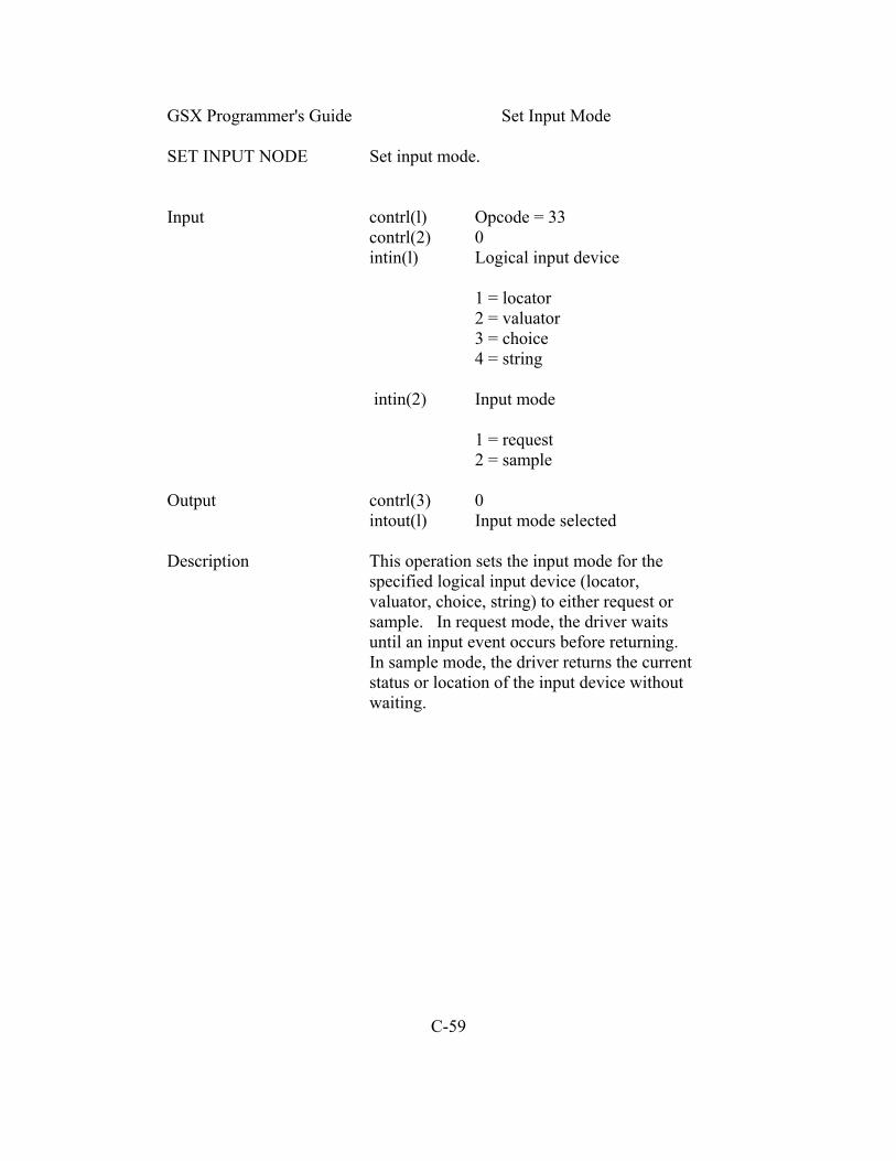
GSX Programmer's Guide Set Input Mode SET INPUT NODE Set input mode. Input contrl(l) Opcode = 33 contrl(2) 0 intin(l) Logical input device 1 = locator 2 = valuator 3 = choice 4 = string intin(2) Input mode 1 = request 2 = sample Output contrl(3) 0 intout(l) Input mode selected Description This operation sets the input mode for the specified logical input device (locator, valuator, choice, string) to either request or sample. In request mode, the driver waits until an input event occurs before returning. In sample mode, the driver returns the current status or location of the input device without waiting. C-59

GSX Programmer's Guide Required Opcode CRT Devices REQUIRED OPCODE The following opcodes and subfunctions are FOR CRT DEVICES required for CRT devices: Table C-2. Opcode for CRT Devices Opcode Description 1 Open workstation 2 Close workstation 3 Clear workstation 4 Update workstation 5 Escape Id Definition 1 Inquire addressable character cells 2 Exit graphics mode 3 Enter graphics mode 4 Cursor up 5 Cursor down 6 Cursor right 7 Cursor left 8 Home cursor 9 Erase to end of screen 10 Erase to end of line 11 Direct cursor address 12 Output cursor addressable text 15 Inquire current cursor address 18 Place graphic cursor 19 Remove graphic cursor 6 Polyline 7 Polymarker 8 Text 9 Filled area 10 Cell array C-60

GSX Programmer's Guide Required Opcode CRT Devices Table C-2. (continued) Opcode Description 11 Graphic Drawing Primitive (GDP) Id Definition 1 Bar Fill 12 Set character height 14 Set color representation 15 Set polyline linetype, 17 Set polyline color index 18 Set polymarker type 20 Set polymarker color index 22 Set text color index 25 Set fill color index 26 Inquire color representation 33 Set input mode (required only if input locator, input valuator, input choice, or input string is present) REQUIRED OPCODE The following opcodes and subfunctions are FOR PLOTTERS AND required for plotters and printers: PRINTERS Table C-2. Opcode for CRT Devices Opcode Definition 1 Open workstation 2 Close workstation 3 Clear workstation 4 update workstation 5 Escape Id Definition 1 Inquire addressable character cells C-61

GSX Programmer's Guide Opcode for Plotters and Printers Table C-2. (continued) Opcode Description 6 Polyline 7 Polymarker 8 Text 9 Filled area 10 Cell array 11 Graphic Drawing Primitive (GDP) Id Definition 1 Bar Fill 12 Set character height 14 Set color representation 15 Set polyline linetype 17 Set polyline color index 18 Set polymarker type 20 Set polymarker color index 22 Set text color index 25 Set fill color index 26 Inquire color representation 33 Set input mode (required only if input locator, input valuator, input choice, or input string is present) Determining if an opcode that is not required is available in a particular driver can be done in a couple of ways. one way is to check the information about available features returned from the OPEN WORKSTATION opcode. Another way is to check the selected value returned from an opcode against the requested value. If the two values do not match, then either the opcode was not available or the requested value was not available, and a best fit value was selected. End of Appendix C C-62

Glossary assignment table Associates logical device numbers, called workstation IDs, with specific GIOS files so that devices can be referred to by number within the application program. The Assignment Table resides in a text file called ASSIGN.SYS and can be modified using any text editor. BDOS Basic Disk Operating System for the CP/M family of operating systems. It contains the device- independent portion of the file system. The device-dependent interface of CP/M is the BIOS (Basic I/O System) module. coordinate scaling Transforms points from one space to another. In GSX all point coordinates must be specif ied in Normalized Device Coordinates with values between 0 and 32,767. GDOS then scales these coordinates into values appropriate for your graphics device. default device Largest driver loaded during a graphics driver session. It is always the first driver named in the Assignment Table. device driver GIOS file that translates standard device- independent graphics operations to graphics specific command sequences for a particular device. Device drivers for graphics devices are contained in the GIOS (Graphics I/O System) portion of GSX. DR Draw Application program that provides an advanced capability to create complex graphics. DR Graph Application program that allows you to graph and plot data by making simple menu selections. function code Number that indicates to the operating system the function that is being requested when a service call is made. Glossary-I

GSX Programmer's Guide Glossary GDOS Graphics Device Operating System, or GDOS, is the device-independent portion of GSX. it services graphics requests and calls GIOS to send commands to graphics devices. Generalized A display function used to address special Drawing device capabilities such as curve drawing. Primitive (GDP) GIN Graphics Input mode GIOS Graphics Input Output System, or GIOS, is the device-dependent portion of GSX. GIOS files are the individual device drivers which translate between a particular device and the standard VDI conventions. GKS Graphical Kernel System graphics mode Entered by executing the GSX command from the operating system's user interface module. This enables all graphics functions. GSX Graphics System Extension, or GSX, is the graphics extension to the 8080 and 8086 family of microcomputer operating systems. Graphical Kernel An international standard for the System (GKS) programming interface to graphics from an application program. graphics Basic graphics operations performed by GSX. primitives for example, drawing lines, markers, and text strings. NDC Normalized Device Coordinates Glossary-2

GSX Programmer's Guide Glossary normalized Uniform virtual space by which a graphics device coordinate application program passes graphics space information to a device. GDOS translates between NDC space and the Display Coordinates (DC) of a particular device. normalized Virtual space in which all point coordinates device coordinates are mapped to values between 0 and 32,767. NDC space serves as a common interface between graphics devices. operation codes Passed to GDOS as part of a parameter list; indicates which graphics operation is requested. VDI Virtual Device Interface virtual device Standard interface between device-dependent interface and device-independent code in a graphics environment. VDI makes all device drivers appear identical to the calling program. GSX is based on VDI, and all device drivers written for GSX must conform to the VDI specification. workstation Graphics device with one display surface and zero or more input devices. workstation Logical unit number that specifies which identification graphics device is currently active. Each number (ID) device driver has an associated workstation ID which is specified in an Assignment Table in file ASSIGN.SYS. End of Glossary Glossary-3
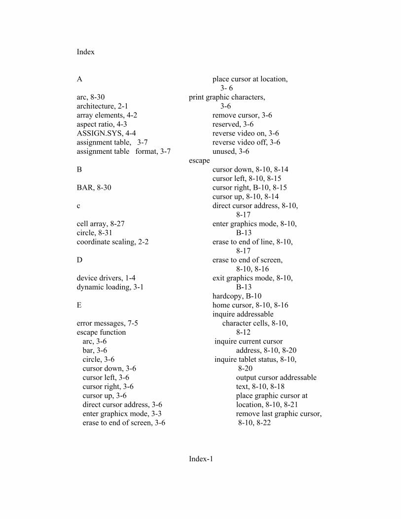
Index A place cursor at location, 3- 6 arc, 8-30 print graphic characters, architecture, 2-1 3-6 array elements, 4-2 remove cursor, 3-6 aspect ratio, 4-3 reserved, 3-6 ASSIGN.SYS, 4-4 reverse video on, 3-6 assignment table, 3-7 reverse video off, 3-6 assignment table format, 3-7 unused, 3-6 escape B cursor down, 8-10, 8-14 cursor left, 8-10, 8-15 BAR, 8-30 cursor right, B-10, 8-15 cursor up, 8-10, 8-14 c direct cursor address, 8-10, 8-17 cell array, 8-27 enter graphics mode, 8-10, circle, 8-31 B-13 coordinate scaling, 2-2 erase to end of line, 8-10, 8-17 D erase to end of screen, 8-10, 8-16 device drivers, 1-4 exit graphics mode, 8-10, dynamic loading, 3-1 B-13 hardcopy, B-10 E home cursor, 8-10, 8-16 inquire addressable error messages, 7-5 character cells, 8-10, escape function 8-12 arc, 3-6 inquire current cursor bar, 3-6 address, 8-10, 8-20 circle, 3-6 inquire tablet status, 8-10, cursor down, 3-6 8-20 cursor left, 3-6 output cursor addressable cursor right, 3-6 text, 8-10, 8-18 cursor up, 3-6 place graphic cursor at direct cursor address, 3-6 location, 8-10, 8-21 enter graphicx mode, 3-3 remove last graphic cursor, erase to end of screen, 3-6 8-10, 8-22 Index-1
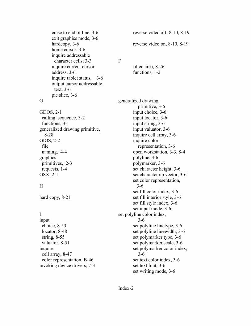
erase to end of line, 3-6 reverse video off, 8-10, 8-19 exit graphics mode, 3-6 hardcopy, 3-6 reverse video on, 8-10, 8-19 home cursor, 3-6 inquire addressable character cells, 3-3 F inquire current cursor filled area, 8-26 address, 3-6 functions, 1-2 inquire tablet status, 3-6 output cursor addressable text, 3-6 pie slice, 3-6 G generalized drawing primitive, 3-6 GDOS, 2-1 input choice, 3-6 calling sequence, 3-2 input locator, 3-6 functions, 3-1 input string, 3-6 generalized drawing primitive, input valuator, 3-6 8-28 inquire cell array, 3-6 GIOS, 2-2 inquire color file representation, 3-6 naming, 4-4 open workstation, 3-3, 8-4 graphics polyline, 3-6 primitives, 2-3 polymarker, 3-6 requests, 1-4 set character height, 3-6 GSX, 2-1 set character up vector, 3-6 set color representation, H 3-6 set fill color index, 3-6 hard copy, 8-21 set fill interior style, 3-6 set fill style index, 3-6 set input mode, 3-6 I set polyline color index, input 3-6 choice, 8-53 set polyline linetype, 3-6 locator, 8-48 set polyline linewidth, 3-6 string, 8-55 set polymarker type, 3-6 valuator, 8-51 set polymarker scale, 3-6 inquire set polymarker color index, cell array, 8-47 3-6 color representation, B-46 set text color index, 3-6 invoking device drivers, 7-3 set text font, 3-6 set writing mode, 3-6 Index-2
L text, 3-6 update workstation, 8-10 loading GIOS files, 3-6 P M pie slice, 8-30 memory management, 3-8 plotters and printers, 8-61 memory requirements, 5-2 polyline, 8-23 polymarker, 8-24 N print graphic characters, 8-31 normalized coordinate space, R 2- 2 Normalized Device Coordinates required opcode CRT Devices, NDC, 3-2 8-60 0 S operation code scaling factor, 4-3 cell array, 3-6 set close workstation, 3-3, 8-9 character height, 8-33 escape, B-10 character up vector, 8-34 filled text, 3-6 color representation, 8-35 fill interior style, 8-42 fill color index, 8-45 fill style index, 8-43 input mode, 8-59 polyline color index, 8-37 polyline line width, 8-37 polyline linetype, B-36 polymarker color index, B-40 polymarker scale, B-38 polymarker type, 8-38 text color index, 8-42 text font, 8-41 writing mode, 8-57 stack requirements, 5-2 T text, B-24 transforming points, 3-2 V Virtual Device Interface VDI, 3- 2 , 4- 2 Index-3