gsmx ð ð ì ì remote monitor and control system user guide version 1.4.pdf · remote monitor and...
TRANSCRIPT
Wireless Solutions at Work www.orbitcoms.com Page 1
Orbit Communications Pty Ltd
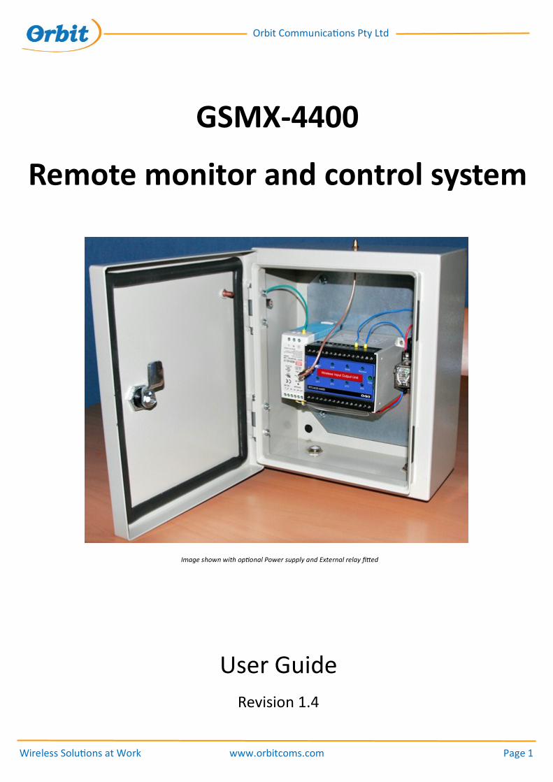
Remote monitor and control system
GSMX-4400
User Guide
Revision 1.4
Image shown with optional Power supply and External relay fitted

Wireless Solutions at Work www.orbitcoms.com Page 2
Orbit Communications Pty Ltd
Orbit Communications Pty Ltd
Unit 1, 16 Donaldson Street
Wyong, NSW 2259
Australia
Phone +61 (2) 43 554 554
Fax +62 (2) 43 554 994
Email [email protected]
Web www.orbitcoms.com
All right reserved
Copyright Orbit Communications Pty Ltd, 2010

Wireless Solutions at Work www.orbitcoms.com Page 3
Orbit Communications Pty Ltd
Table of Contents
Introduction 4
How it works 5
Alert Messages 6
Installation 7
Power Supply 7
Antenna 7
SIM Card 8
Installing SIM card 10
Running the Software 12
LED Status Panel 16
Start Up Sequence 17
Mains Loss detection 18
Battery Low Detection 18
Text Commands 19
Alert Messages 20
Relay Details 21
Safety Precautions 22
Warranty 23

Wireless Solutions at Work www.orbitcoms.com Page 4
Orbit Communications Pty Ltd
Introduction
The GSMX-4400 system is designed to provide reliable monitoring of equipment attached to the system at
remote locations in addition to providing remote control of equipment connected to system by mobile phone
commands. The system operates on both GSM and Next-G/3G mobile phone networks.
System options include
- Solar Power Supply - Battery backup with trickle charger
- Alert messages sent direct to computer - 230VAC power supply
Figure 1. System Overview Diagram
Head Office:
Main Pump
OFF
Request Status
from any mobile phone
Receive Alerts with
up to 10 mobile phones
or Computer
GSMX4400 4 Din, 4 Dout
Sends text alert up to 10 mobile phones
Mains Loss/Restore function
Low Battery/Restore function
IP67 waterproof/dustproof enclosure
12/24V DC operation
Low power suits solar power supply
Control outputs from any mobile phone
Obtain system status any time using mobile phone
Indoor or outdoor use
12 months warranty
Full technical support from manufacturer
Supplied with convenient setup software

Wireless Solutions at Work www.orbitcoms.com Page 5
Orbit Communications Pty Ltd
How it works
Overview:
GSMX-4400 is supplied with Windows© based software called “EzGSM”. The software enables up to 10
mobile phone numbers to be defined, a description for the site, a description for each Digital input and
Output as well as the Polarity of Digital Input alarms.
The system requires a user-supplied SIM card. The SIM card is available from mobile phone vendors. It is
recommended the SIM is not “Pre-Paid” as the GSMX™ system has no way of determining when the card’s
credit expires. The SIM card should also have the PIN number removed before using with GSMX-4400. This
can be done by the provider or by placing the SIM card into a mobile phone and disabling the SIM PIN feature
using the phone’s setup function.
The standard GSMX-4400 system requires 12V or 24V DC to operate. The system can be provided with
optional Mains Plug-Pack, 230VAC supply(as shown in picture on front page) or Solar power supply.
Types of Input:
The GSMX-4400 system can accept a variety of digital inputs and control a variety of ON/OFF outputs.
Typical Inputs and Outputs:
Switches
Relay contacts
PLC inputs and outputs
Push buttons
Solenoid valves
Relays
Digital temperature probe, Cable length limited to 5m from enclosure
Wireless Solutions at Work www.orbitcoms.com Page 6
Orbit Communications Pty Ltd
Alert Messages
GSMX-4400 can send several types of text message to the mobile phone numbers setup using the EzGSM
software.
When the system is powered up, a “Power Up” system message will be sent to notify that the system has
been switched on.
If the 230VAC mains supply or Mains plug-pack option is fitted, the system will send a “Mains Loss” alert if the
mains power supply is lost at any time. A “Mains Restore” message will be sent when power is restored after
a mains loss occurs.
The system also monitors the Battery voltage (if solar power supply or battery backup is fitted). In event the
battery voltage drops below 10.5V a “Low Battery” alert message will be sent. Once the battery level is re-
stored (rises above 11.5V) a “Battery Restore” message will be sent.
Sending commands to GSMX-4400 from mobile phone
The current Digital input and output states and Battery voltage can be obtained at any time using any mobile
phone. The user sends a user defined password followed by the word “status” to the GSMX-4400 unit. The
unit will then send back the current Input and outputs status as well as Battery voltage to the mobile phone
that sent the request.
The digital outputs can be controlled by mobile phone by sending a command to switch either output ON or
OFF. This is typically useful for activating a cooling fan or other device in event of over or under temperature
situation.
The GSMX-4400-OD unit can be supplied pre-fitted with a 230VAC/10A rated relay contact for each output.
This option needs to be requested at time of ordering the system.

Wireless Solutions at Work www.orbitcoms.com Page 7
Orbit Communications Pty Ltd
Installation
Locating the unit:
The GSMX4400 Unit should be located close to the points being monitored. If the Orbit Digital temperature
sensor is being used, the probe must be located with the 5m maximum length of the cable.
Power Supply:
GSMX-4400 requires an operating voltage of 12V or 24V DC with current capacity up to 1.5Amps peak. The
system can be powered by 230 VAC/12V Plug-pack, 230VAC fixed-wired supply or backup battery that is
connected to a charging unit or Solar panel rated at 10W or higher. These options are available from Orbit
Communications Pty Ltd.
Antenna:
The GSMX-4400 is supplied with a GSM Antenna fitted directly to the top of the enclosure. The unit should be
located in a position where there is suitable GSM signal strength to operate reliably on the GSM or Next-G mo-
bile phone networks. This location can easily be determined using the signal strength indicator on a mobile
phone. Metal objects should not be located closely to the GSM antenna.
Wireless Solutions at Work www.orbitcoms.com Page 8
Orbit Communications Pty Ltd
GSM Dialler
GSMX-4400-OD contains a GSM/Next-G dialler unit that will operate on worldwide GSM and Next-G/3G mobile
phone networks. All that is needed to use the GSMX unit is an active SIM card. These cards are normally pro-
vided through mobile phone vendors.
Note: It is recommended NOT to use a pre-paid SIM card as the system has know means to identify when the
card requires topping up.
Some SIM cards supplied have PIN Numbers (It is recommended the PIN is removed before attempting to use the SIM with the GSMX
device).
This process can be done by the SIM card provider at time of purchase of the SIM or the PIN can be removed by placing into a mobile
phone and disable the PIN number. (Refer to your mobile phone user guide for details of how to disable the PIN function on the SIM
card).

Wireless Solutions at Work www.orbitcoms.com Page 9
Orbit Communications Pty Ltd
Setting up GSMX-4400
The GSMX-4400 system can be configured using Windows® software called “EzGSM”. This software is used to
set up the system. The preferred method of installation is from Orbit’s Updates web site. The install program
can be located at http://orbitcoms.com/updates/ezgsmdn/setupEzGSM.htm . Click “Install” from the web site to install
the program directly from the web site. Once installed, the EzGSM software will check for updates every time
the program is run to ensure it is the latest version.
Using EzGSM setup software
EzGSM must first be installed onto a desktop or laptop computer. The software is used to program the settings
into the GSMX-4400 unit. Once GSMX-4400 has been set up, the cable can be removed and the system will op-
erate as programmed. The settings will remain in the GSMX-4400 unit even after power down and can only be
modified using EzGSM software.
Serial Port GSMX-4400 connects to the computer using an RS485 serial link. A DB9 connector is wired directly to the GSMX-4400 unit inside the enclosure. A RS485 to USB adaptor device is provided to enable the unit to attach to a computer for setting up. A disk with drivers for various operating systems is provided with the system.
USB to RS485 Adaptor

Wireless Solutions at Work www.orbitcoms.com Page 10
Orbit Communications Pty Ltd
To insert SIM Card:
The SIM card is inserted into a socket behind the front panel. To install the SIM the plastic front panel must be removed.
This is done my carefully wedging a small screwdriver in the slot at the top of the plastic front panel.
Be careful to only lift the plastic cover
until it comes clear of the top as shown.
Do NOT stretch the thin cable that
connects GSM antenna to front
Wireless Solutions at Work www.orbitcoms.com Page 11
Orbit Communications Pty Ltd
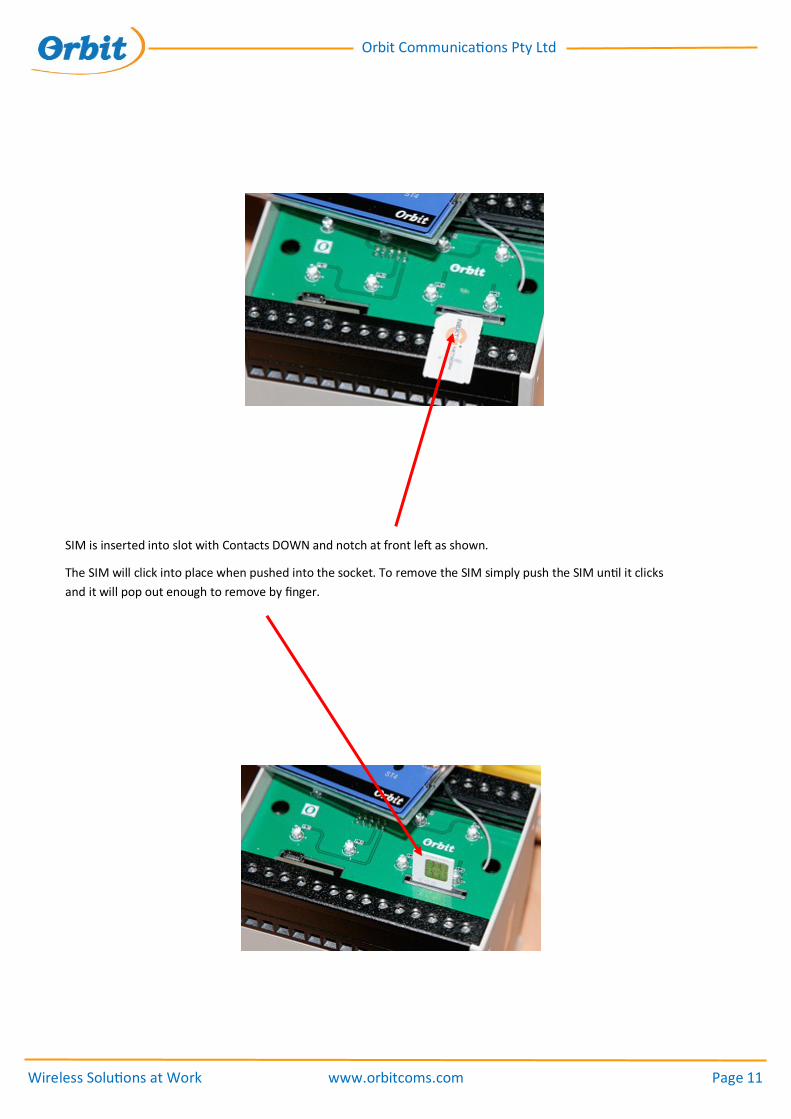
SIM is inserted into slot with Contacts DOWN and notch at front left as shown.
The SIM will click into place when pushed into the socket. To remove the SIM simply push the SIM until it clicks
and it will pop out enough to remove by finger.
Wireless Solutions at Work www.orbitcoms.com Page 12
Orbit Communications Pty Ltd
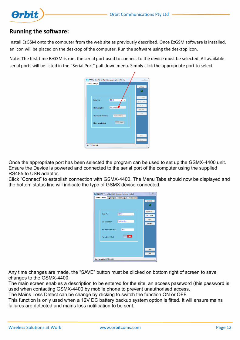
Running the software:
Install EzGSM onto the computer from the web site as previously described. Once EzGSM software is installed,
an icon will be placed on the desktop of the computer. Run the software using the desktop icon.
Note: The first time EzGSM is run, the serial port used to connect to the device must be selected. All available
serial ports will be listed in the “Serial Port” pull down menu. Simply click the appropriate port to select.
Once the appropriate port has been selected the program can be used to set up the GSMX-4400 unit. Ensure the Device is powered and connected to the serial port of the computer using the supplied RS485 to USB adaptor. Click “Connect” to establish connection with GSMX-4400. The Menu Tabs should now be displayed and the bottom status line will indicate the type of GSMX device connected.
Any time changes are made, the “SAVE” button must be clicked on bottom right of screen to save changes to the GSMX-4400. The main screen enables a description to be entered for the site, an access password (this password is used when contacting GSMX-4400 by mobile phone to prevent unauthorised access. The Mains Loss Detect can be change by clicking to switch the function ON or OFF. This function is only used when a 12V DC battery backup system option is fitted. It will ensure mains failures are detected and mains loss notification to be sent.

Wireless Solutions at Work www.orbitcoms.com Page 13
Orbit Communications Pty Ltd
The GSMX is provided with NO phone numbers set up. Before the system can send SMS alerts, at least one
phone number must be entered (Note: The system will still receive SMS commands from mobile phones even
when no phone numbers are set as it will return the result to the calling phone).
Select “Phone Book” tab to set up phone numbers.
Click “ADD” button to add a new mobile phone number to the list. Up to 10 Mobile phone numbers can be
used. Edit the “Contact Name” box to enter a description of the phone number and then the phone number in
the “Mobile Phone Number” box. The number can be entered in local format “0459563898” or international
format “+61459563898”. (Do not add “ marks).
Numbers can be removed by selecting a number in the list and click “Remove”.
Numbers can be edited by selecting number in list and selecting “Edit”
Click “SAVE” to save the phone numbers to GSMX-4400 when done.

Wireless Solutions at Work www.orbitcoms.com Page 14
Orbit Communications Pty Ltd
To set up the Outputs. Select the “Relay outputs” tab.
The various text details are sent with each SMS alert message and when requesting status information and
other SMS commands.
The description of each output can be entered in “Title” box. [8 Characters max]
“ON Text” is the text shown when the Relay is activated (ON). [7 Characters max]
“OFF Text” is text shown when the Relay is deactivated (OFF). [7 Characters max]
The relay can be manually switched ON and OFF by licking the “Set State” switch. Ie. The actual relay on the
GSMX-4400 unit will switch ON and OFF in real time when these buttons are pressed.
“Current State” Displays the actual real time current state of the Relay.
Example:
Relay 1 may be used to control a Generator. The Title might be set as say “Genset”, the ON text as “Running”
and Off text as “Stopped”.
If Relay 1 was activated and a status request was sent to the unit then the text shown for that relay would be…
“GenSet Running”
Click “Save” when done to save changes to GSMX-4400.
Wireless Solutions at Work www.orbitcoms.com Page 15
Orbit Communications Pty Ltd
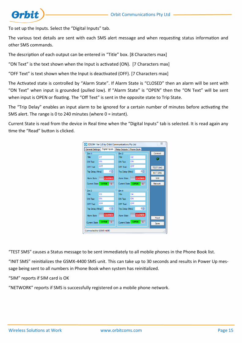
To set up the Inputs. Select the “Digital Inputs” tab.
The various text details are sent with each SMS alert message and when requesting status information and
other SMS commands.
The description of each output can be entered in “Title” box. [8 Characters max]
“ON Text” is the text shown when the Input is activated (ON). [7 Characters max]
“OFF Text” is text shown when the Input is deactivated (OFF). [7 Characters max]
The Activated state is controlled by “Alarm State”. If Alarm State is “CLOSED” then an alarm will be sent with
“ON Text” when input is grounded (pulled low). If “Alarm State” is “OPEN” then the “ON Text” will be sent
when input is OPEN or floating. The “Off Text” is sent in the opposite state to Trip State.
The “Trip Delay” enables an input alarm to be ignored for a certain number of minutes before activating the
SMS alert. The range is 0 to 240 minutes (where 0 = instant).
Current State is read from the device in Real time when the “Digital Inputs” tab is selected. It is read again any
time the “Read” button is clicked.
“TEST SMS” causes a Status message to be sent immediately to all mobile phones in the Phone Book list.
“INIT SMS” reinitializes the GSMX-4400 SMS unit. This can take up to 30 seconds and results in Power Up mes-
sage being sent to all numbers in Phone Book when system has reinitialized.
“SIM” reports if SIM card is OK
“NETWORK” reports if SMS is successfully registered on a mobile phone network.

Wireless Solutions at Work www.orbitcoms.com Page 16
Orbit Communications Pty Ltd
LED Status Panel
The front panel has a number of LEDs that indicate particular conditions for the system.
Figure 2. LED Status Panel
Power
Wireless Input Output Unit
Orbit
Link Send Receive
Radio
ST1 ST2 ST3 ST4
RTU433-4400
LED Description Function
Power Power Indicator ON when unit has power
Link Run Indicator Blinks during normal operation
Send Send Status Blinks when sending an SMS message
Receive Receive Status Blinks when receiving an SMS message
ST1 R1 Status ON when R1 is activated
ST2 R2 Status ON when R2 is activated
ST3 R3 Status ON when R3 is activated
ST4 R4 Status ON when R4 is activated

Wireless Solutions at Work www.orbitcoms.com Page 17
Orbit Communications Pty Ltd
Start Up Sequence
The POWER LED should initially come on and then blink at a rate of around 1 second for approximately 12 seconds.
After this time the POWER LED should be ON solid.
The LINK LED should come on after a short time. This indicates the SMS module is working correctly.
Next, the SEND LED will be switched ON. This indicates the SIM card is ready and ok to use.
Finally the RECEIVE LED should be switched ON to indicate the system has registered ok with mobile phone network.
A short time later, the 4 bottom row LEDs should light in sequence and then go OFF.
Now a Power up message will be sent.
When ever a message is being sent the SEND LED will come on for around 5-6 seconds. If the message is successfully transferred to
the mobile phone network then the SEND LED will blink 3 times and switch OFF.
A Power up message should be received on all mobile phones entered in the Phone Book.
Receiving a SMS:
The RECEIVE LED should light briefly and then switch OFF.
Then the normal Send sequence described above should occur as the GSMX-4400 proceeds to send the response to the mobile that
send the SMS to the unit. Note: Only the mobile which sent the request will receive a response, whereas ALL phones in the Phone
book will receive Alert messages generated by the GSMX-4400.

Wireless Solutions at Work www.orbitcoms.com Page 18
Orbit Communications Pty Ltd
Main Loss Detection
A check box in the General settings area of the EzGSM screen contains a checkbox labelled
“Mains Loss Detect”.
This is to be selected when a battery back-up system option has been installed. When selected, the GSMX unit
will send a Mains Loss SMS alert when the mains power that is charging the battery is lost. The detection may
take up to 5 minutes.
If the mains is restored then a Mains Restore message will be sent. The mains loss occurs when the input sup-
ply voltage falls below 12.9V DC. (Note: If the charger is not being used this feature should not be enabled as
an alarm will be sent when power supply voltage is below 12.9V DC). The Mains Restore level occurs at
13.3V DC.
Battery Low Detection
If the battery voltage falls below 10.7V DC, a Low Battery SMS message alert will be sent. A Battery Restore
message will be sent when voltage rises above 11.5V DC.
The current Battery/Supply voltage can be determined by selecting “Read Device” option in EzGSM software or
by requesting “status” using mobile phone.
Wireless Solutions at Work www.orbitcoms.com Page 19
Orbit Communications Pty Ltd
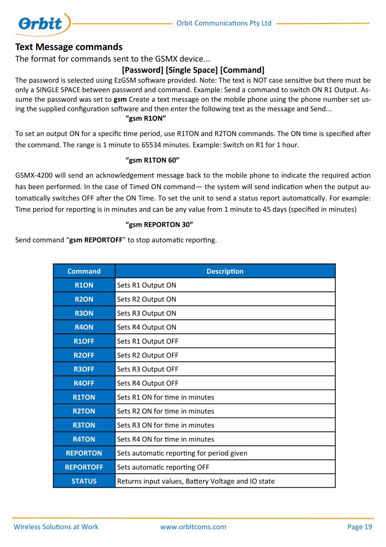
Text Message commands The format for commands sent to the GSMX device...
[Password] [Single Space] [Command] The password is selected using EzGSM software provided. Note: The text is NOT case sensitive but there must be only a SINGLE SPACE between password and command. Example: Send a command to switch ON R1 Output. As-sume the password was set to gsm Create a text message on the mobile phone using the phone number set us-ing the supplied configuration software and then enter the following text as the message and Send... “gsm R1ON”
To set an output ON for a specific time period, use R1TON and R2TON commands. The ON time is specified after
the command. The range is 1 minute to 65534 minutes. Example: Switch on R1 for 1 hour.
“gsm R1TON 60”
GSMX-4200 will send an acknowledgement message back to the mobile phone to indicate the required action
has been performed. In the case of Timed ON command— the system will send indication when the output au-
tomatically switches OFF after the ON Time. To set the unit to send a status report automatically. For example:
Time period for reporting is in minutes and can be any value from 1 minute to 45 days (specified in minutes)
“gsm REPORTON 30”
Send command “gsm REPORTOFF” to stop automatic reporting.
Command Description
R1ON Sets R1 Output ON
R2ON Sets R2 Output ON
R3ON Sets R3 Output ON
R4ON Sets R4 Output ON
R1OFF Sets R1 Output OFF
R2OFF Sets R2 Output OFF
R3OFF Sets R3 Output OFF
R4OFF Sets R4 Output OFF
R1TON Sets R1 ON for time in minutes
R2TON Sets R2 ON for time in minutes
R3TON Sets R3 ON for time in minutes
R4TON Sets R4 ON for time in minutes
REPORTON Sets automatic reporting for period given
REPORTOFF Sets automatic reporting OFF
STATUS Returns input values, Battery Voltage and IO state

Wireless Solutions at Work www.orbitcoms.com Page 20
Orbit Communications Pty Ltd
Text Alert messages
The following messages are sent from GSMX™ (x is dependant on model of GSMX used)
Message Description
Din (x) Alarm Digital Input chan (x) alarm
Din (X) OK Digital Input chan (x) OK
Mains Loss Detected loss of mains power
Mains Restore Mains power has been restored
Low Battery Backup Battery below 10.5V
Battery OK Backup Battery OK
Power Up System has been powered up
Status Returns Input values, Battery and IO Status
Example of sent text alert. Note: Text may be different dependant on what text was set up using
EZGSM.
“New Site:”
“D1 Alarm”

Wireless Solutions at Work www.orbitcoms.com Page 21
Orbit Communications Pty Ltd
Maximum Voltage = 230 VAC
Maximum Current = 2A
Bottom row of Terminals
+Ve
GN
D
GN
D
GN
D
GN
D
GN
D
GN
D
GN
D
GN
D
+Ve
+Ve
D1
D2
D3
D4
D1 to D4 = Digital input
GND = Power supply negative, ground
+Ve = Power supply positive 12 or 24V DC
D1
GND
Switch, Relay or PLC output
Typical Digital Input wiring
Top row of Terminals
OP
4
A
CL1
OP
1
CM
2
OP
2
CM
4
OP
3
CL3
CL4
CM
3
B
GN
D
CM
1
CL2
“CLx” = Normally Closed
“CMx” = Common
“OPx” = Normally Open
Relay 4 Relay 3 Relay 2 Relay 1 RS485
Details of Relay contacts
Wireless Solutions at Work www.orbitcoms.com Page 22
Orbit Communications Pty Ltd
Digital Inputs
The Digital Inputs are pulled up to +3.3V DC via an internal pull-up resistor. The
inputs can tolerate over voltage and reverse polarity voltage to +/- 30V DC.
Voltages applied outside of this range may cause damage.
The Digital inputs can be operated using any voltage free contact (such as a Relay
contact, open drain or open collector output from another device or a switch), the
input can also be connected to a voltage source (recommend 0V to 10V
maximum). Note: The Common side of the input devices must connect to the
GROUND terminal of the RTU device.
Relay Outputs
The RTU Relay outputs are rated at maximum load of 230VAC and 2 Amps.
Additional voltage or current capacity can be obtained by addition of external
relays. Orbit can provide external relays and latching relays.
Wireless Solutions at Work www.orbitcoms.com Page 23
Orbit Communications Pty Ltd
Safety Precautions The following safety precautions must be observed whenever the Orbit wireless device system is in operation or in service. Failure to comply with these precautions violates the safety standards of the design, manufacture and intended use of the product
- The system is not to be used:
In hospitals or places where medical equipment may be in use.
In an aircraft (whether on the ground or in the air)
Refuelling points
Explosive areas
- Restricted use of the Orbit wireless device
Near any chemical plant
Near any Fuel depot
The Orbit wireless device system receives and transmits radio frequency energy while switched on, therefore interference can occur if the Orbit wireless device is located near TVs, radios, PCs or any inadequately shielded equipment.
WEEE directive 2002/96/EC, disposal of old electronic equipment
This product shall not be treated as household waste. It must be placed at an appropriate collection point for the recycling of electrical and electronic equipment. By ensuring the correct disposal of this equipment, it will help the environment and human’s health. The recycling will help to conserve the natural resources.
Important
Due to the nature of wireless systems, transmission and reception of data can never be guaranteed. Data may be corrupted (i.e. Have errors) or be totally lost at certain times due to the environment, other machinery or malfunction of electronic components. Although significant loss of data are rare when wireless devices such as the Orbit wireless device system are used in a normal manner, Orbit’s wireless device system should not be used in situations where failure to transmit or receive data could result in damage of any kind to the user or any other party, including but not limited to personal injury, death or loss of property. Orbit Communications Pty Ltd accepts no responsibility for damages of any kind resulting from errors in data transmitted or received using Orbit’s Orbit wireless device systems, or for the failure of the Orbit wireless device system to transmit or receive such data.
Do not operate the Orbit wireless device system in areas where blasting is in progress, where explosive at-mospheres may be present, near medical equipment, near life support equipment, or any equipment which may be susceptible to any form of radio interference, in such areas, Orbit’s wireless device system must be powered OFF.
Wireless Solutions at Work www.orbitcoms.com Page 24
Orbit Communications Pty Ltd
Do not operate Orbit wireless device system in any aircraft, whether the aircraft is on the ground or in flight. In an aircraft the Orbit wireless device system must be powered OFF.
The information in Orbit Communications Pty Ltd documents are subject to change without notice and do not represent a commitment on the part of Orbit Communications Pty Ltd. Orbit Communications Pty Ltd and its affiliates specifically disclaim liability for any and all direct, indirect, special, general, incidental, consequential, punitive or exemplary damages including, but not limited to, loss of profits or revenue or anticipated profits or revenue arising out of the use or inability to use any Orbit Communications Pty Ltd product, even if Orbit Communications Pty Ltd and/or its affiliates have been advised of the possibility of such damages or they are foreseeable or for claims by any third party.
Notwithstanding the foregoing, in no event shall Orbit Communications Pty Ltd and/or its affiliates aggregate liability arising under or in connection with the Orbit Communications Pt Ltd product, regardless of the number of events, occurrences or claims giving rise to liability, be in excess of the price paid by the purchaser for the Orbit Communications Pty Ltd product.
Warranty All products manufactured by Orbit Communications Pty Ltd are warranted to be free from defects in materials and workmanship under normal use and service for 12 months from the date of shipment unless otherwise specified. Orbit Communications’ obligation under this warranty is limited to repairing or replacing (at Orbit’s discretion) defective products. The customer shall assume all costs of removing, reinstalling and shipping defective products to Orbit Communications. Orbit Communications will return such products by surface carrier prepaid. This warranty shall not apply to any Orbit product that has been subject to modification, misuse, neglect, accidents of nature or shipping damage. This warranty is in lieu of all other warranties, expressed or implied, including warranties of merchantability or fitness for a particular purpose. Orbit Communications is not liable for special, indirect, accidental, or consequential damages. Products may not be returned to Orbit Communications without prior authorization. To obtain a Returned Product Authorization (RPA), contact Orbit Communications by phone, fax or email. An RPA number will be issued after our staff determines the nature of the problem. Please write the RPA number on the outside of the shipping container. Any non-warranty products returned for repair should be accompanied by a purchase order to cover the cost of the repairs.