g.shdsl. bis vpn router -...
TRANSCRIPT

1
6200 SERIES
G.SHDSL.BIS
VPN ROUTER
USER MANUAL
VERSION 1.00

2
Context
1 INTRODUCTION ................................................................................................................................................. 1
1.1 DESCRIPTIONS ...................................................................................................................................................... 1
1.2 FEATURES ............................................................................................................................................................ 2
1.3 SPECIFICATIONS .................................................................................................................................................... 2
2 GETTING TO KNOW ABOUT THE VPN ROUTER ................................................................................................... 6
2.1 FRONT PANEL....................................................................................................................................................... 6
2.2 REAR PANEL......................................................................................................................................................... 7
2.3 WAN PORT ......................................................................................................................................................... 8
2.2. LAN PORTS ....................................................................................................................................................... 10
2.3. CONSOLE PORT .................................................................................................................................................. 10
2.4 USB PORT ........................................................................................................................................................ 11
2.5 POWER CONNECTION .......................................................................................................................................... 11
2.6 RESET BUTTON ................................................................................................................................................... 11
2.7 PROTECTIVE EARTH (FRAME GROUND) TERMINAL ..................................................................................................... 12
3 CONFIGURATION ..............................................................................................................................................12
3.1 CONFIGURATION METHODS .................................................................................................................................. 12
3.1.1. Web Configuration .................................................................................................................................... 12
3.1.2. Serial Console Configuration ..................................................................................................................... 13
3.1.3. Telnet Configuration .................................................................................................................................. 13
3.1.4. Installation ................................................................................................................................................ 14
3.1.5. Login via Web Browser .............................................................................................................................. 16
3.2 MENU TREE ...................................................................................................................................................... 17
3.3 QUICK SETUP ..................................................................................................................................................... 24
3.3.1. System Mode ............................................................................................................................................. 24
3.4 NETWORK ......................................................................................................................................................... 30
3.4.1. SHDSL ........................................................................................................................................................ 30
3.4.2. Interfaces .................................................................................................................................................. 32
3.4.3. 3.5G Backup .............................................................................................................................................. 34
3.4.4. DNS ........................................................................................................................................................... 35
3.4.5. DHCP ......................................................................................................................................................... 36
3.4.6. NAT ............................................................................................................................................................ 36
3.5. ADVANCE .......................................................................................................................................................... 37
3.5.1. STP ............................................................................................................................................................ 37
3.5.2. VLAN ......................................................................................................................................................... 38
3.5.3. Q-in-Q ........................................................................................................................................................ 44
3.5.4. Switch ........................................................................................................................................................ 47

3
3.5.5. Static Route ............................................................................................................................................... 47
3.5.6. QoS ............................................................................................................................................................ 48
3.5.7. RIP ............................................................................................................................................................. 54
3.5.8. Virtual Server ............................................................................................................................................ 55
3.5.9. DMZ........................................................................................................................................................... 56
3.1.6. DDNS ......................................................................................................................................................... 56
3.5.10. IGMP..................................................................................................................................................... 57
3.6. SECURITY .......................................................................................................................................................... 57
3.6.1. Firewall ..................................................................................................................................................... 57
3.6.2. VPN ........................................................................................................................................................... 60
3.6.3. Filter .......................................................................................................................................................... 67
3.7 MANAGEMENT .................................................................................................................................................. 70
3.7.1. SNTP .......................................................................................................................................................... 70
3.7.2. SNMP ........................................................................................................................................................ 71
3.7.3. TR-069 ....................................................................................................................................................... 72
3.7.4. UPnP .......................................................................................................................................................... 73
3.7.5. Sys Log....................................................................................................................................................... 73
3.7.6. Telnet ......................................................................................................................................................... 74
3.7.7. SSH ............................................................................................................................................................ 74
3.7.8. Web ........................................................................................................................................................... 75
3.8 SHOW .............................................................................................................................................................. 75
3.8.1. Information ............................................................................................................................................... 76
3.8.2. Sys Log....................................................................................................................................................... 77
3.8.3. CPU Info .................................................................................................................................................... 77
3.8.4. Script ......................................................................................................................................................... 78
3.9 STATUS ............................................................................................................................................................. 79
3.9.1. SHDSL ........................................................................................................................................................ 79
3.9.2. WAN .......................................................................................................................................................... 80
3.9.3. Route Table................................................................................................................................................ 80
3.9.4. Interfaces .................................................................................................................................................. 81
3.9.5. STP ............................................................................................................................................................ 81
3.9.6. Switch ........................................................................................................................................................ 82
3.10 UTILITIES ........................................................................................................................................................... 83
3.10.1. Upgrade ................................................................................................................................................ 83
3.10.2. Config Tool ............................................................................................................................................ 83
3.10.3. Users ..................................................................................................................................................... 85
3.10.4. Ping ...................................................................................................................................................... 86
3.10.5. Trace Route ........................................................................................................................................... 87
4 TERMINOLOGY ................................................................................................................................................ 88

1
11 IInnttrroodduuccttiioonn
11..11 DDeessccrriippttiioonnss
6200 series G.SHDSL.bis VPN Router is a high performance 4 ports Security Gateway providing Internet access and
LAN-to-LAN application over existing copper line for small/medium office. Complying with ITU-T G.991.2 (2004)
standard, 6200 series make full use of the advanced G.SHDSL.bis technology to offer data transmission rates of up
to 5.696Mbps in 2-wire mode, 11.392Mbps in 4-wire mode and 22.784Mbps in 8-wire mode.
6200 series VPN Router is integrated high-end Bridging/Routing capabilities with advanced functions of Multi-DMZ,
Virtual Server mapping, and VPN pass-through. Because of rapid growth of network, virtual LAN has become one of
the major new areas in internetworking industry. 6200 support port-based VLAN and IEEE 802.1q VLAN over ATM
network.
With always on connection that DSL features, 6200 series VPN routers provide advanced firewall with SPI (Stateful
Packet Inspection) and DoS protection, serving as a powerful firewall to protect from outside intruders of secure
connection. It also supports IP precedence to classify and prioritize types of IP traffic. In additional, its VPN feature
supports data transmission over the Internet by data encryption/decryption between two sites. VPNs feature allows
replacing a private leased line to minimize the expense among global inter-connection.
Not only the much higher bandwidth than convention symmetric digital subscriber loop, 6200 series also provide
the network administrators tool of Quality of Service (QoS) to allocate network resources effectively. By classify the
priority of services, the functions of bandwidth management increases efficiency and productivity on specific demands
such as VoIP, video streaming, video-conferencing or interactive game applications to guarantee all the application get
the deserved service quality.

2
11..22 FFeeaattuurreess
� Easy configuration and management with password control for various application environments
� Efficient IP routing and transparent learning bridge to support Internet broadband services
� Virtual LANs (VLANs) offer significant benefit in terms of efficient use of bandwidth, flexibility, performance and
security
� VPN for safeguarded connections
� Built-in advanced SPI firewall
� IP precedence to partition the traffic into multiple classes of service
� Four 10/100M Base-T Auto-sensing, Auto-negotiation and Auto-MDI/MDIX switching port for flexible local area
network connectivity
� USB ports for 3.5G USB dangle modem for Internet access backup(For USB models only)
� Fully ATM protocol stack implementation over SHDSL.bis
� PPPoA and PPPoE support user authentication with PAP/CHAP/MS-CHAP/MS-CHAPv2
� SNMP management with SNMPv1/v2c/v3 agent and MIB II
� Getting enhancements and new features via Internet software upgrade
11..33 SSppeecciiffiiccaattiioonnss
� Hardware Interface
� WAN Port:
� SHDSL.bis: ITU-T G.991.2 (2004) Annex A/B/F/G supported
� Encoding scheme: TC-PAM 16/ TC-PAM 32
� Data Rate: N x 64kbps (N= 3 ~ 89, 89 as default) (For 6200-2W and 6200-2W/U)
� Data Rate: N x 128kbps (N= 3 ~ 89, 89 as default) (For 6200-4W and 6200-4W/U)
� Data Rate: N x 256kbps (N= 3 ~ 89, 89 as default) (For 6200-8W and 6200-8W/U)
� Impedance: 135 ohms
� LAN Port: 4-Ports 10/100M Switch supports
� Auto-negotiation for 10/100Base-TX and Half/Full Duplex
� Auto-MDIX
� USB Port: 2-ports USB (For 6200-2W/U, 6200-4W/U and 6200-8W/U)
� USB 2.0
� Serial Console Port: RJ45 connector
� Factory Default Reset: Push Button
� LED:
� Power (Green)
� WAN LINK/ACT(Green), one LED per pair
� LAN (Port 1~port 4) LINK/ACT (Green)

3
� ALARM (Red)
� Bridging and VLAN
� IEEE 802.1D Transparent Learning Bridge
� IEEE 802.1Q and Port Based VLAN
� Spanning Tree Protocol (STP)
� Up to 2K Mac Address
� Routing
� Static routing and RIP v1/v2(RFC 1058/2453)
� NAT/PAT (RFC1631)
� NAT Application Level Gateways
� Skype/MSN/Yahoo Messenger (RFC2933)
� VoIP(SIP) pass through
� VPN PPTP/L2TP pass through
� Virtual Server
� Network Protocol
� IPv4 (ARP/RARP, TCP/UDP,ICMP)
� DHCP Client/Server, Relay
� DNS Relay/Proxy, Dynamic DNS(DDNS)
� IGMP v1/v2/v3, IGMP Proxy, IGMP Snooping
� SNTP and UPnP
� ATM
� 8 PVC
� OAM F4/F5 Loopback
� AAL5
� VC Multiplexing and SNAP/LLC
� Ethernet over ATM (RFC 2684/RFC1483)
� Multiple protocol over ATM AAL5(MPOA, REF1483/2684)
� PPP over ATM (RFC 2364)
� Classic IP over ATM (RFC 1577)
� QoS(UBR/CBR/VBR/VBR-RT)
� PPP
� PPPoE
� PAP/CHAP/MS-CHAP/MS-CHAPv2
� Configurable timer to auto-reconnect,

4
� Configurable Idle times for timeout
� QoS
� 802.1P Tag
� IPv4 TOS/DiffServ
� Class-based Prioritization
� Class-based Traffic Shaping
� Class-based DSCP Mark
� Up to 8 priority queues
� IP Precedence Alternation
� VPN
� IPSec (RFC2411) up to 4 Tunnels
� DES/3DES/AES
� MD5/SHA-1
� IKE/Manual Key
� ISAKMP (RFC 2407/2408/4306)
� IKE v1 (RFC 2409/4109)
� PSK
� L2TP/PPTP
� Firewall
� SPI (Stateful Packet Inspection)
� Intrusion Detection/DoS (Denial of Service)
� DMZ
� Content Filtering
� URL Blocking
� Packet Filtering/Access Control List (ACL)

5
� Management
� Web and Telnet management via LAN ports
� CLI via serial console port
� Support SSH (RFC4250/4251/4252/4253/4254/4255/4256)
� SNMP v1/v2c/v3 (RFC 1157/1901//1905)
� MIB II (RFC 1213/1493)
� Syslog with Remote Logging support
� Firmware Upgrade via TFTP
� Configuration Data Import/Export
� Multiple Levels of Administration Privilege
� Support TR-069 WAN management protocol
� Physical / Electrical
� Dimensions: 18.7 x 3.3 x 14.5cm (WxHxD)
� Power: 100~240VAC (via power adapter)
� Power Consumption: 9 watts Max
� Temperature: 0~40ºC
� Humidity: 0%~95%RH (non-condensing)
Model Number list:
Model Number
Specification 6200-2W 6200-4W 6200-8W 6200-2W/U 6200-4W/U 6200-8W/U
Maximum DSL wires 2-wires 4 -wires 8-wires 2-wires 4 -wires 8-wires
Maximum data rate 5.696 Mbps 11.392 Mbps 22.784 Mbps 5.696 Mbps 11.392 Mbps 22.784 Mbps
USB port USB port for 3.5G Dangle Modem with
Internet access backup

6
22 GGeettttiinngg ttoo kknnooww aabboouutt tthhee VVPPNN RRoouutteerr
22..11 FFrroonntt PPaanneell
LED status of VPN Router:
LEDs Active Description
PWR On The power adaptor is connected to this device
DSL
LINK 1
On SHDSL.bis line 1 connection is established
Blink SHDSL.bis line 1 handshake
Transmit or received data over SHDSL.bis link 1
LINK 2
On SHDSL.bis line 2 connection is established
Blink SHDSL.bis line 2 handshake
Transmit or received data over SHDSL.bis link 2
LINK 3
On SHDSL.bis line 3 connection is established
Blink SHDSL.bis line 3 handshake
Transmit or received data over SHDSL.bis link 3
LINK 4
On SHDSL.bis line 4 connection is established
Blink SHDSL.bis line 4 handshake
Transmit or received data over SHDSL.bis link 4
LAN
LINK/ACT1 On Ethernet cable is connected to LAN 1
Blink Transmit or received data over LAN 1
LINK/ACT2 On Ethernet cable is connected to LAN 2
Blink Transmit or received data over LAN 2
LINK/ACT3 On Ethernet cable is connected to LAN 3
Blink Transmit or received data over LAN 3
LINK/ACT4 On Ethernet cable is connected to LAN 4
Blink Transmit or received data over LAN 4
ALM
On SHDSL.bis line connection is dropped
Blink SHDSL.bis self test
Off No Alarm

7
22..22 RReeaarr PPaanneell
Connector Description
DC-IN Power adaptor inlet: Input voltage from 9V to 12VDC
CONSOLE RJ-45 for system configuration and maintenance
RST Reset button for reboot or load factory default
LAN (1,2,3,4) 10/100BaseT auto-sensing and auto-MDIX for LAN port (RJ-45)
USB USB ports ( for 6200-2W/U, 6200-4W/U and 6200-2W/U only)
DSL G.SHDSL .Bis interface for WAN port (RJ-45)
Frame Ground / Protective earth

8
22..33 WWAANN PPoorrtt
The VPN Router have one port for WAN port connection, this is a G.SHDSL .Bis interface.
The pin assignments for SHDSL line cable are:
For 2-wire (one pair) model , Loop1 has been used.
For 4-wire (two pair) model, Loop1 and 2 have been used.
For 8-wire (four pair)model, Loop1, 2, 3 and 4 have been used.
Channel A Channel B Channel C Channel D
2-wire model (6200-2W , 6200-2W/U)
2-wire mode Loop1 (4,5)
4-wire model (6200-4W , 6200-4W/U)
2-wire mode
4-wire mode
Loop1 (4,5)
Loop1 (4,5) Loop2 (3,6)
8-wire model (6200-8W , 6200-8W/U)
2-wire mode
4-wire mode
8-wire mode
Loop1 (4,5)
Loop1 (4,5) Loop2 (3,6)
Loop1 (4,5) Loop3 (1,2) Loop4 (7,8) Loop2 (3,6)
For test on point to point connection purpose, you can use the Straight-Through Ethernet Cable for SHDSL.bis link as
the following.

9
T-568A Straight-Through Ethernet Cable
T-568B Straight-Through Ethernet Cable
Both the T-568A and the T-568B standard Straight-Through cables are been used.

10
22..22.. LLAANN ppoorrttss
The VPN Router have four LAN ports. Those ports are auto-negotiating, auto-crossover. In 10/100Mbps Fast Ethernet,
the speed can be 10Mbps or 100Mbps and the duplex mode can be half duplex or duplex.
The auto-negotiating ports can detect and adjust to the optimum Ethernet speed (10/100 Mbps) and duplex mode (full
duplex or half duplex) of the connected device. The auto-crossover (auto-MDI/MDI-X) ports automatically works
with a straight-through or crossover Ethernet cable.
22..33.. CCoonnssoollee PPoorrtt
Connect the RJ-45 jack of the console cable to the console port of the VPN Router. Connect the DB-9 female end to a
serial port( COM1 , COM2 or other COM port) of your computer.
The wiring diagram of console cable is as following:

11
The pin assignment of RJ-45 modular jack on the Console cable:
Pin Number Abbrev. Description Figure
1 DSR DCE ready 1 8
1 8
Top View
Front View
2 DCD Received Line Signal Detector
3 DTR DTE ready
4 GND Signal Ground
5 RXD Received Data
6 TXD Transmitted Data
7 CTS Clear to Send
8 RTS Request to Send
22..44 UUSSBB PPoorrtt
Only for with USB ports models. This is using for connection of 3G/3.5G USB modem.
22..55 PPoowweerr ccoonnnneeccttiioonn
Make sure you are using the correct power source as the AC/DC adaptor. Inset the female end of power adaptor’s
cord into the power receptacle on the rear panel. Connect the power adaptor to an appropriate power source.
22..66 RReesseett BBuuttttoonn
The reset button can be used only in one of two ways.
(1) Press the Reset Button for two second will cause system reboot.
(2) Pressing the Reset Button for eight seconds will cause the product loading the factory default setting and losing
all of yours configuration. When you want to change its configuration but forget the user name or password, or if the
product is having problems connecting to the Internet and you want to configure it again clearing all configurations,
press the Reset Button for eight seconds with a paper clip or sharp pencil.

12
22..77 PPrrootteeccttiivvee EEaarrtthh ((FFrraammee GGrroouunndd)) tteerrmmiinnaall
The marked lug or terminal should be connected to the building protective earth bus. The function of protective
earth does not serve the purpose of providing protection against electrical shock, but instead enhances surge
suppression on the DSL lines for installations where suitable bonding facilities exist. The connector type is M3
machine screw.
33 CCoonnffiigguurraattiioonn
33..11 CCoonnffiigguurraattiioonn MMeetthhooddss
There are three methods to configure the VPN Router: serial console, Telnet and Web Browser. Users have to
choose one method to configure the VPN Router.
33..11..11.. WWeebb CCoonnffiigguurraattiioonn
Make sure that Ethernet Adapter had been installed in PC or NB used for configuration of the modem. TCP/IP
protocol is necessary for web configuration, so please check the TCP/IP protocol whether it has been installed.
The VPN Router provides a browser interface that allows you to configure and manage this device. After you set up
your IP address for the VPN Router, you can access the VPN Router’s Web interface applications directly in your
browser by entering the IP address of the VPN Router. You can then use your Web browser to list and manage
configuration parameters from PC.
Web Configuration requires Internet Explorer 5.0 or later or Netscape Navigator 6.0 and later versions. The
recommended screen resolution is 1024 by 768 pixels.

13
33..11..22.. SSeerriiaall CCoonnssoollee CCoonnffiigguurraattiioonn
The console port is a RJ-45 connector that enables a connection to a PC for monitoring and configuring the VPN Router.
Use the supplied serial cable with a female DB-9 connector to serial port of PC and RJ-45 module jack connector to
VPN Router’s console port. Start your terminal access program by terminal emulation program or Hyper Terminal
and configure its communication parameters to match the following default characteristics of the console port:
Parameter Value
Baud Rate 115200
Data Bits 8
Parity Check None
Stop Bits 1
Flow Control None
It will ask for user name and password in order to remote login when using telnet, please use “root” for username and
“root” for password. Please check the following screen shot for what you will see in your terminal window.
33..11..33.. TTeellnneett CCoonnffiigguurraattiioonn
The VPN Router also supports telnet for remote management. Please make sure the correct Ethernet cable
connected the LAN ports of device to your computer. The LAN indicator on the front panel shall light on if a correct
cable is used. Start your telnet client with a command window or VT100 terminal emulation by key in “192.168.0.1”,
which is the management IP address of 6200 series VPN router, and wait for the login page prompts up. Then, key
in the user name and the password once the login page shows. The login page is shown as the following screen shot.
(The default user name and password are “root” and “root”.)

14
All display screens are as same as serial console configuration. The default IP address is “192.168.0.1” and you can
customerize the IP address for you application. In addition, the default Telnet function is disable. Therefore, before
using this Telnet function, please enable Telnet with using Web management .
33..11..44.. IInnssttaallllaattiioonn
This following guide is designed to lead users through Web Configuration of G.shdsl.bis VPN Router in the easiest and
quickest way possible. Please follow the instructions carefully.
Step 1. Connect the power adapter to the port labeled “DC-IN” on the rear panel of the VPN Router.
Step 2. Connect the Ethernet cable to LAN ports. (Note: The VPN Router supports auto-MDIX switching hub so
both straight through and cross-over Ethernet cables can be used.)
Step 3. Connect the phone cable to the VPN Router and the other side of phone cable to wall jack.
Step 4. Connect the power adapter to power source.
Step 5. Turn on the PC or NB, which is used for configuration the VPN Router.
! To avoid possible damage to this VPN Router, DO NOT turn on this device before Hardware Installation.

15
Connection with VPN Router

16
33..11..55.. LLooggiinn vviiaa WWeebb BBrroowwsseerr
This section introduces the configuration and functions of the web-based management. It is an HTML-based
management interface that allows users to setup and manage 6200 VPN routers. This configuration system offers
all monitoring and management features which allow users to access VPN routers from anywhere on the network with
a standard browser, such as, Internet Explorer or Firefox.
Step 1. User can use any common browsers, such as, Internet Explorer, on your computer to connect the VPN
Router. Then, please type “http://192.168.0.1” in the address bar of the browser.
Step 2. The default IP address and sub net-mask of the management port of VPN Router are “192.168.0.1” and
“255.255.255.0”.
Step 3. If DHCP function is Disable, your computer can set the same net-mask such as 192.168.0.X which X is from 2
to 254, that are also can connect.
Step 4. Key in user name, “root”, and password, “root”; then, click on “Login” button to login the web configuration.
Note: Both the default user name and password are “root”. It is suggested to change the user name and the
password for security reason.
Note: For safety purpose, the password will be prompt as star symbol.
Note: Once you change the user name and password, please login with the new user name and password in the next
login process.
17
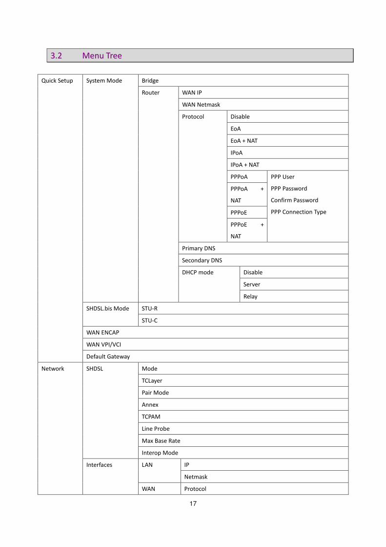
33..22 MMeennuu TTrreeee
Quick Setup System Mode Bridge
Router WAN IP
WAN Netmask
Protocol Disable
EoA
EoA + NAT
IPoA
IPoA + NAT
PPPoA PPP User
PPP Password
Confirm Password
PPP Connection Type
PPPoA +
NAT
PPPoE
PPPoE +
NAT
Primary DNS
Secondary DNS
DHCP mode Disable
Server
Relay
SHDSL.bis Mode STU-R
STU-C
WAN ENCAP
WAN VPI/VCI
Default Gateway
Network SHDSL Mode
TCLayer
Pair Mode
Annex
TCPAM
Line Probe
Max Base Rate
Interop Mode
Interfaces LAN IP
Netmask
WAN Protocol

18
ENCAP
VPI-VCI
QoS Class
QoS PCR
QoS SCR
3.5G Backup Mode
Location
ISP
Manufacture
Dial Number
APN
Keep-alive Interval
Keep-alive Server
DNS Primary
Secondary
DHCP Mode Disable
Server
Relay
DHCP Server Mode
Subnet
Netmask
IP Range
Gateway
DNS
Lease Time
DHCP Relay IP
Interface
NAT Mode
Entry (1~16) Enable
Source IP
Source Netmask
Output Interface
Advance STP Router Mode Not available
Bridge Mode Mode
Aging Time
VLAN Router Mode Not available
Bridge Mode Mode Disable
802.1Q Tag-Based VLAN

19
Port-Based VLAN
QinQ Router Mode Not available
Bridge Mode Mode Disable
Mapping
By VLAN
By WAN
Switch Port 1 ~ Port 4 Auto
100M/Full
100M/Half
10M/Full
10M/Half
Static Route Destination
Netmask
Gateway
Interface
QoS Mode
Traffic Classify Mode
Class ID
Protocol
Src IP
Src Netmask
Src Port
Dst IP
Dst Netmask
Dst Port
802.1P Class ID
IP DSCP DSCP
Class ID
Class Shaping Mark Mode
DSCP
TOS
Min Rate
Max Rate
RIP Mode
RIP Version
LAN Mode
Passive
WAN1~WAN8 Mode

20
Passive
Virtual Server Router Mode Mode
Entry (1~16) Enable
Description
Interface
Protocol
Public Port
Private IP/Port
Bridge Mode Not available
DMZ Router Mode Mode
WAN I/F
Host IP
Bridge Mode Not available
DDNS Mode
Provider
Host Name
User Name
Password
IGMP IGMP Proxy / Snooping
Security Firewall Router Mode Mode
Bridge Mode Not available
VPN Router Mode IPSEC Mode
Name
WAN
Perfect Forward Secrecy
Local Subnet
Local Netmask
Remote Public IP
Remote Local LAN Subnet
Remote Local LAN Netmask
Pre-shared Key
L2TP Mode
Authentication
Virtual IP
L2TP/IPSec Mode
IPSec Interface
IPSec PSK
User

21
PPTP Mode
Authentication
Virtual IP
User
Bridge Mode Not available
Filter IP Filter Mode
Default Policy
Entry(1~16) Mode
Action
Protocol
Source IP/ Mask
Source Start/ End Port
Destination IP/ Mask
Destination Start/ End Port
MAC Filter Mode
Default Policy
Entry(1~16) Mode
MAC
Action
Management SNTP Sync With PC
SNTP Mode
Time Server
Time Zone
SNMP SNMPv3 Mode
V3 User Name
V3 Auth. Password
V3 Priv. Password
V3 Auth. Mode
V3 Auth. Type
V3 Priv. Type
V3 Access
Trap Mode
Community
Trap Host IP
TR069 Mode
ACS URL
ACS Username
ACS Password

22
Periodic Inform Enable
Periodic Inform Interval
Periodic Inform Time
Connection Request IP
Connection Request Port
Connection Request Username
Connection Request Password
Retry Times
UPnP Mode
Sys Log Remote Server Mode
Remote Server Address
Remote Server Port
Telnet Mode
Port
SSH Mode
Port
Web Refresh Time
Service Port
Show Information Hardware MCSV
Software MCSV
Software Version
DSL Chip Name
DSL Phy Firmware Version
DSL IDC Firmware Version
MAC
Serial No
Present Time
System Uptime
Sys Log
Script
Status SHDSL
WAN
Route Table
Interfaces
STP (not available in router mode)
Utilities Upgrade
Config Tool Default
Backup

23
Restore
Users User 1~4 Name
Level
Password
Confirm
Ping IP Address
Size
Count
Update
Trace Route Host name or IP
Packet Datagram
Update Interval

24
33..33 QQuuiicckk SSeettuupp
“Quick Setup” function guides users to setup their VPN routers step by step. This VPN Router can be set as a bridge
or a router. The following sections show how to setup a bridge mode or a router mode.
33..33..11.. SSyysstteemm MMooddee
“System Mode” allows users to decide this VPN router should be a bridge device or a router device.
“Router mode” is when the DSL modem performs all the functions that allow you to connect to the Internet which
include: all the technical settings (VCI, encapsulation, etc.) and the VPN router also connects to the ISP with your
username and password. You can basically just connect to your computer.
“Bridge mode”, on the other hand, allows some external device, for example, your computer or a separate router, to
do the ISP connection, etc. In bridge mode, all the VPN router does is remembering your VCI, VPI and encapsulation
settings. The ISP information and IP address assigned is controlled b your separate router or computer in PPP mode.
33..33..11..11 BBrriiddggee MMooddee
Click on “Bridge” to set this VPN router as a bridge device.

25
Once a user chooses “Bridge” mode, two more setups will be shown: “WAN ENCAP” and “WAN VPI/VCI”.
WAN ENCAP
There are two encapsulation types: VC-Mux (Virtual Circuit Multiplexing) and LLC(Logical Link Control). VC-MUX and
LLC are two mechanisms for identifying the protocol carried in ATM Adaptation Layer 5 (AAL5) frames.
WAN VPI/VIC
There is an unique VPI and VCI value for Internet connection supported by ISP. The range of VIP is from 0 to 255, and
VCI is from 0 to 65535.
33..33..11..22 RRoouutteerr MMooddee
Click on “Router” to assign this VPN router to be a router device.
Once “System Mode” is set to “Router”, more setups will be shown as the screen shot above.

26
WAN Section
Fill up the information in the circled section in order to complete setting up your VPN router as a router device.
1. WAN IP and WAN Netmask
Fill up the IP address and the netmask of WAN.
2. Protocol
Nine options are available for this setup:
� Disable
� EoA
� EoA + NAT
� IPoA
� IPoA + NAT
� PPPoA
� PPPoA + NAT
� PPPoE
� PPPoE + NAT
3. WAN ENCAP
Choose either “LLC” or “VC MUX” for WAN encapsulation.
4. WAN VPI/VCI
Define the values of VPI and VCI.

27
DNS
Two sets of DNS addresses can be stored in DNS section.
DHCP Mode
Choose whether DHCP mode should be disabled or enabled. If the DHCP mode should be enabled, decide the mode
should be “Server” or “Relay”.
PPP
This section is only available when the protocol is PPPoA, PPPoA + NAT, PPPoE, or PPPoE + NAT.

28
In this section, you are able to set PPP user, PPP password, and PPP connection type. In addition, the connection
type can be set as either “Always on” or “On demand”.
33..33..11..33 SSHHDDSSLL..bbiiss mmooddee
There are two SHDSL.bis modes: STU-C and STU-R. “STU-C” means the terminal of central office (CO) and “STU-R”
means customer premise equipment (CPE). Click STU-R side or STU-C side to setup the operation mode. When
connected with DSLAM, the mode should be CPE. When “LAN to LAN” connection, one side must be CO and the
other side must be CPE.

29
33..33..11..44 LLAANN IIPP aanndd SSuubbnneett MMaasskk
In both “Bridge” mode and “Router” mode, the IP address and subnet mask of LAN should be provided.
33..33..11..55 DDeeffaauulltt GGaatteewwaayy
“Default Gateway” allows users to fill up the gateway IP address in both “Bridge” mode and “Router” mode.

30
33..44 NNeettwwoorrkk
Network section allows users to setup the following functions.
1. SHDSL
2. Interfaces
3. 3.5G Backup
4. DNS
5. DHCP
6. NAT
Please check the sections for detail information on how to use these functions.
33..44..11.. SSHHDDSSLL
1. Mode:
You are able to change your VPN router’s mode to STU-R or STU-C in here.
2. TC Layer
Three options are available for this function: ATM, EFM or AUTO. You are able to define the network type as an
ATM connection or an EFM connection. Or you are able to set TC layer as AUTO so the VPN router will define by
itself.
Note: AUTO will be only available when the VPN router is in STU-R mode.

31
3. Pair Mode
This feature allows you to choose how many wire you would like to use on SHDSL.bis connection.
Line Type Mode
VPN Router
2-wire
(1 pair)
4-wire
(2 pair)
8-wire
(4 pair)
6200-2W 6200-2W/U ●
6200-4W 6200-4W/U ● ●
6200-8W 6200-8W/U ● ● ●
The table above indicates the model number and its corresponding available wire numbers. For example:
6200-2W and 6200-2W/U (2-wire model) can select 2-wire line type only.
6200-4W and 6200-4W/U (4-wire model) can select 2-wire and 4-wire line types.
6200-8W and 6200-8W/U (8-wire model) can select 2-wire, 4-wire or 8-wire line types.
4. Annex
There are four Annex types, Annex A, Annex B, Annex A/F and Annex B/G. Please confirm with your ISP.
5. TCPAM
Three options are available for TCPAM feature, “Auto”, “TCPAM-16” and “TCPAM-32”. “Auto” means the system
will choose TCPAM automatically and this option is only available when the Annex type is “Annex A/F” or “Annex
B/G”.
ATM Mode
SHDSL.bis VPN
Router Annex A Annex B Annex A/F Annex B/G
Auto ● ●
TCPAM-16 ● ●
TCPAM-32 ● ●
TCPAM-64
TCPAM-128
EFM Mode
SHDSL.bis VPN
Router Annex A/F Annex B/G
Auto ● ●
TCPAM-16 ● ●
TCPAM-32 ● ●
TCPAM-64 ● ●
TCPAM-128 ● ●
32
6. Line Probe
You are able to choose to disable or enable “Line Probe” function for adpative mode of data rate. When “Line
Probe” function is enabled, the system will search on the best connection based on the value of “Max Base Rate”
automatically.
7. Max Base Rate
This value will be used for “Line Probe” in order to find the best connection when line probe function is enabled.
In addition, the value range is differed according to Annex type.
SHDSL.bis VPN
Router Annex A Annex B Annex A/F Annex B/G
Range 3 ~ 36 3 ~ 36 3 ~ 89 3 ~ 89
8. Interop Mode
This feature allows you to enable or disable the interoperability of G.SHDSL version for the VPN router by
choosing “NONE” or “GSPN”.
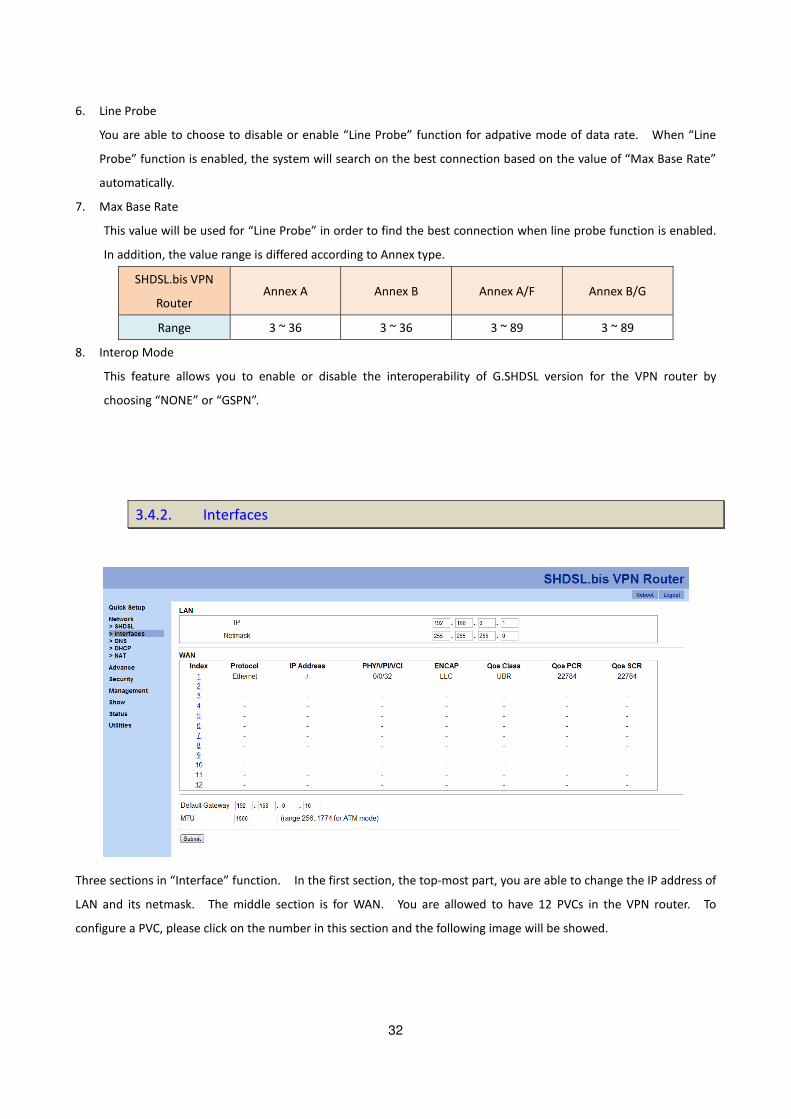
33..44..22.. IInntteerrffaacceess
Three sections in “Interface” function. In the first section, the top-most part, you are able to change the IP address of
LAN and its netmask. The middle section is for WAN. You are allowed to have 12 PVCs in the VPN router. To
configure a PVC, please click on the number in this section and the following image will be showed.

33
In the last section of this page, you can define the IP address of the default gateway and the size of MTU.
QQooSS CCllaassss
The router supports UBR, CBR, VBR-rt and VBR-nrt.
UBR (Unspecified Bit Rate) is the simplest service provided by ATM networks. There is no guarantee of anything. It is a
primary service used for transferring Internet traffic over the ATM network.
CBR (Constant Bit Rate) is used by connections that requires a static amount of bandwidth that is avilable during the
connection life time. This bandwidth is characterized by Peak Cell Rate (PCR). Based on the PCR of the CBR traffic,
specific cell slots are assigned for the VC in the schedule table. The ATM always sends a signle cell during the CBR
connection’s assigned cell slot.
VBR-rt (Varible Bit Rate real-time) is intended for real-time applications, such as compressed voice over IP and video
comferencing, that require tightly constrained delays and delay variation. VBR-rt is characterized by a peak cell rate
(PCR), substained cell rate (SCR), and maximun burst rate (MBR).
VBR-nrt (Varible Bit Rate non-real-time) is intended for non-real-time applications, such as FTP, e-mail and browsing.

34
QQooSS PPCCRR
PCR (Peak Cell Rate) in kbps: The maximum rate at which you expect to transmit data, voice and video. Consider PCR
and MBS as a menas of reducing lantency, not increasing bandwidth.
QQooSS SSCCRR
SCR (Substained Cell Rate): The sustained rate at which you expect to transmit data, voice and video. Consider SCR to
be the true bandwidth of a VC and not the lone-term average traffic rate.
33..44..33.. 33..55GG BBaacckkuupp
This function is for 6200-2W/U, 6200-4W/U and 6200-8W/U.
VPN Router with USB models are supports automatic backup function. When connecting with SHDSL.bis, it will enable
the 3G/3.5G broadband connection automatically when SHDSL.bis Internet connection is not available. You can surf
Internet anywhere and anytime via this device.
3G/3.5G Modem card installation:
If you have 3G/3.5G modem card and SIM card, please follow the following instructions to establish connection
1. Connect power adapter to VPN router
2. Connect another Ethernet cable from the any LAN ports (1~4) on VPN router to the
Ethernet socket on the PC
3. Insert SIM card into 3G/3.5G modem card, and connect the modem card with one of USB ports of VPN router.
3G/3.5G Internet Configuration
VPN Router supports most of 3G/3.5G modem cards, just connect the modem card to the USB port of this device
35
will recognize it automatically, no additional setup procedure required.
Only one Internet connection (3G/3.5G wireless / DSL wired) can be used at the same time.
At first, DSL wired Internet connection will be selected, and use wireless connection (3G/3.5G) as backup. For example,
if you connect 3G/3.5G modem card with VPN Router when you’re using wired Internet connection, when DSL wired
connection dropped and 3G/3.5G wireless connection will start up.
PIN code or user name / password required
Please check the authentication method you want to use. Most of telecomm service providers require you to input
Dial Number and APN (Access Point Name), please those items provided by telecomm service provider.
After finish type those items, then click ‘APPLY’ button.
Note: Different ISP’s require Dial Number and APN for connecting to the Internet, please check with your ISP as to the
type of connection it requires.
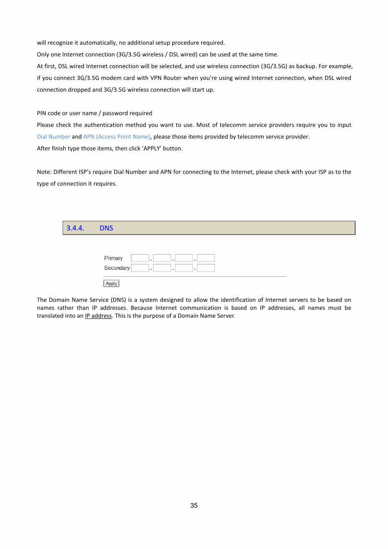
33..44..44.. DDNNSS
The Domain Name Service (DNS) is a system designed to allow the identification of Internet servers to be based on
names rather than IP addresses. Because Internet communication is based on IP addresses, all names must be
translated into an IP address. This is the purpose of a Domain Name Server.

36
33..44..55.. DDHHCCPP
Dynamic Host Configuration Protocol (DHCP) is a communication protocol that lets network administrators to manage
centrally and automate the assignment of Internet Protocol (IP) addresses in an organization's network. Using the
Internet Protocol, each machine that can connect to the Internet needs a unique IP address. When an organization sets
up its computer users with a connection to the Internet, an IP address must be assigned to each machine.
Without DHCP, the IP address must be entered manually at each computer. If computers move to another location in
another part of the network, a new IP address must be entered. DHCP lets a network administrator to supervise and
distribute IP addresses from a central point and automatically sends a new IP address when a computer is plugged into
a different place in the network.
33..44..66.. NNAATT
NAT (Network Address Translation) is the translation of an Internet Protocol address (IP address) used within one
37
network to a different IP address known within another network. One network is designated the inside network and
the other is the outside. Typically, a company maps its local inside network addresses to one or more global outside IP
addresses and reverse the global IP addresses of incoming packets back into local IP addresses. This ensure security
since each outgoing or incoming request must go through a translation process, that also offers the opportunity to
qualify or authenticate the request or match it to a previous request. NAT also conserves on the number of global IP
addresses that a company needs and lets the company to use a single IP address of its communication in the Internet
world.
33..55.. AAddvvaannccee
Note: The advanced functions are only for advanced users to setup advanced functions. The incorrect setting of
advanced function will affect the performance or system error, even disconnection.
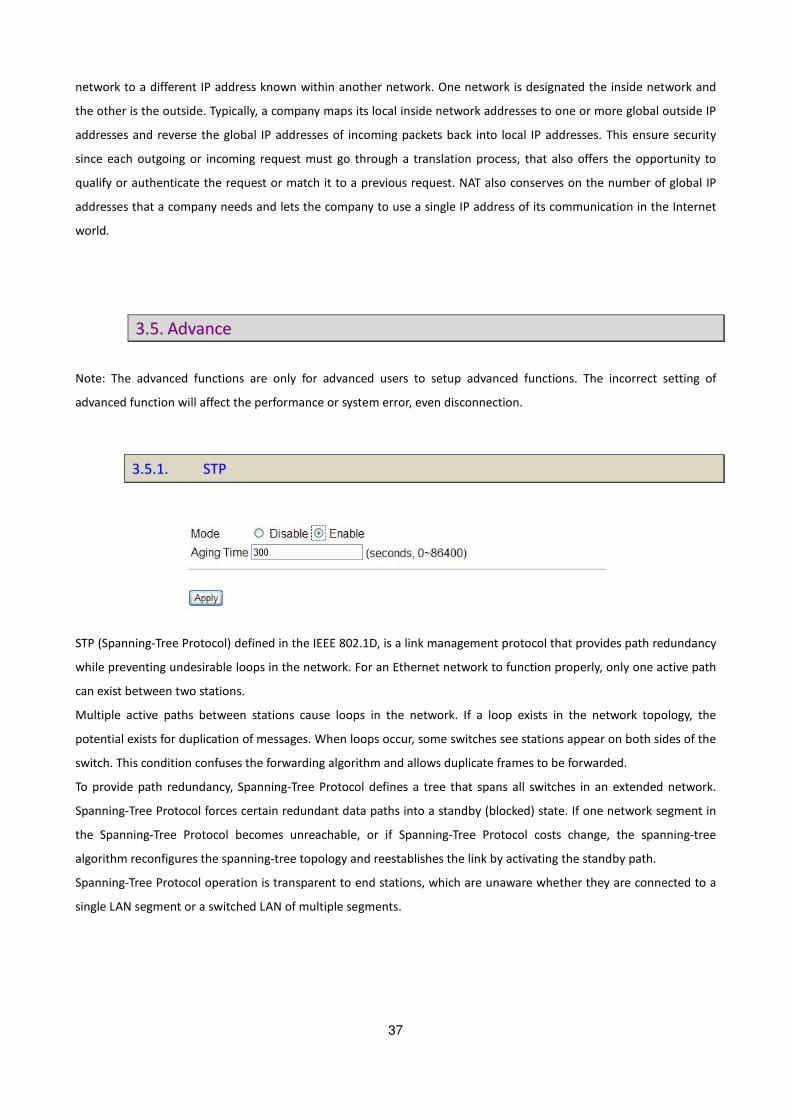
33..55..11.. SSTTPP
STP (Spanning-Tree Protocol) defined in the IEEE 802.1D, is a link management protocol that provides path redundancy
while preventing undesirable loops in the network. For an Ethernet network to function properly, only one active path
can exist between two stations.
Multiple active paths between stations cause loops in the network. If a loop exists in the network topology, the
potential exists for duplication of messages. When loops occur, some switches see stations appear on both sides of the
switch. This condition confuses the forwarding algorithm and allows duplicate frames to be forwarded.
To provide path redundancy, Spanning-Tree Protocol defines a tree that spans all switches in an extended network.
Spanning-Tree Protocol forces certain redundant data paths into a standby (blocked) state. If one network segment in
the Spanning-Tree Protocol becomes unreachable, or if Spanning-Tree Protocol costs change, the spanning-tree
algorithm reconfigures the spanning-tree topology and reestablishes the link by activating the standby path.
Spanning-Tree Protocol operation is transparent to end stations, which are unaware whether they are connected to a
single LAN segment or a switched LAN of multiple segments.

38
33..55..22.. VVLLAANN
VLAN is for Bridge mode only.
VLAN (Virtual Local Area Network) allows a physical network to be partitioned into multiple logical networks. Devices
on a logical network belong to one group. A device can belong to more than one group. With VLAN, a device cannot
directly talk to or hear from devices that are not in the same group.
With MTU (Multi-Tenant Unit) applications, VLAN is vital in providing isolation and security among the subscribers.
When properly configured, VLAN prevents one subscriber from accessing the network resources of another on the
same LAN.
VLAN also increases network performance by limiting broadcasts to a smaller and more manageable logical broadcast
domain. In traditional switched environments, all broadcast packets go to each every individual port. With VLAN, all
broadcasts are confined to a specific broadcast domain.
User can choose three types of VLAN: 802.1Q Tag-Based VLAN and Port-Based VLAN. You can also set Disable the VLAN
function.
The VLAN Setup screen changes depending on whether you choose 802.1Q Tag-Based VLAN type and Port Based VLAN
types in this screen.
The IEEE 802.1Q defines the operation of VLAN bridges that permit the definition, operation, and administration of
VLAN topologies within a bridged LAN infrastructure.

39
40
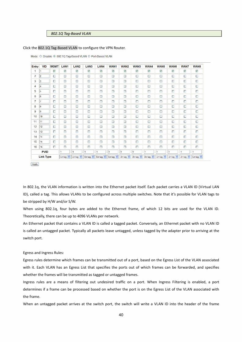
880022..11QQ TTaagg--BBaasseedd VVLLAANN
Click the 802.1Q Tag-Based VLAN to configure the VPN Router.
In 802.1q, the VLAN information is written into the Ethernet packet itself. Each packet carries a VLAN ID (Virtual LAN
ID), called a tag. This allows VLANs to be configured across multiple switches. Note that it’s possible for VLAN tags to
be stripped by H/W and/or S/W.
When using 802.1q, four bytes are added to the Ethernet frame, of which 12 bits are used for the VLAN ID.
Theoretically, there can be up to 4096 VLANs per network.
An Ethernet packet that contains a VLAN ID is called a tagged packet. Conversely, an Ethernet packet with no VLAN ID
is called an untagged packet. Typically all packets leave untagged, unless tagged by the adapter prior to arriving at the
switch port.
Egress and Ingress Rules:
Egress rules determine which frames can be transmitted out of a port, based on the Egress List of the VLAN associated
with it. Each VLAN has an Egress List that specifies the ports out of which frames can be forwarded, and specifies
whether the frames will be transmitted as tagged or untagged frames.
Ingress rules are a means of filtering out undesired traffic on a port. When Ingress Filtering is enabled, a port
determines if a frame can be processed based on whether the port is on the Egress List of the VLAN associated with
the frame.
When an untagged packet arrives at the switch port, the switch will write a VLAN ID into the header of the frame

41
according to the PVID (port VLAN) port definition. Typically, most switches today have all ports are set to a default
PVID of 1. When a tagged frame arrives at a switch port the tag is respected.
A VID defines the member of a port group. A packet can only travel inside a member port when the member port is
part of a VID port group. Different VID groups aren’t visible to one another
VID: (Virtual LAN ID) It is an definite number of ID which number is from 1 to 4094.
PVID: (Port VID) It is an untagged member from 1 to 4094 of default VLAN.
Link Type: Access means the port can receive or send untagged packets.
Trunk means that the prot can receive or send tagged packets.
TCI (Tag Control Information field) including user priority, Canonical format indicator(CFI) and VLAN ID.
TPID(Tag Protocol Identifier) defined value of 8100 in hex. When a frame has the EtherType equal to 8100H, this frame
carries the tag IEEE 802.1Q / 802.1P.
Priority field defines user priority, giving eight (23 = 8) priority levels. IEEE 802.1P defines the operation for these 3
user priority bits.(Refer to following table)
CFI(Canonical Format Indicator) is always set to zero for Ethernet switches. CFI is used for compatibility reason
between Ethernet type network and Token Ring type network. If a frame received at an Ethernet port has a CFI set to
1, then that frame should not be forwarded as it is to an untagged port.
VID (VLAN ID) is the identification of the VLAN, which is basically used by the standard 802.1Q. It has 12 bits and allow
the identification of 4096 (212
) VLANs. Of the 4096 possible VIDs, a VID of 0 is used to identify priority frames and
value 4095 (FFF) is reserved, so the maximum possible VLAN configurations are 4,094.
The VPN Router initially default configures one VLAN, VID=1.
A port such as LAN1 to 4, DSL or sniffing can have only one PVID, but can have as many VID as the VPN Router has
memory in its VLAN table to store them.

42
Ports in the same VLAN group share the same frame broadcast domin thus increase network
performance through reduced boardcast traffic. VLAN groups can be modified at any time by adding, moving or
changing ports without any re-cabling.
Before enabling VLANs for the VPN Router, you must first assign each port to the VLAN group(s) in which it will
participate. By default all ports are assigned to VLAN1 as untagged ports. Add a port as a tagged port if you want it to
carry traffic for one or more VLANs, and any intermediate network devices or the host at the other end of the
connection supports VLANs. Then assign ports on the other VLAN-aware network devices along the path that will carry
this traffic to the same VLAN(s), either manually or dynamically using GVRP. However, if you want a port on this VPN
Router to participate in one or more VLANs, but none of the intermediate network devices nor the host at the other
end of the connection supports VLANs, then you should add this port to the VLAN as an untagged port.
Note: VLAN-tagged frames can pass through VLAN-aware or VLAN-unaware network
Inter-connection devices, but the VLAN tags should be stripped off before passing it on to any end-node host that
does not support VLAN tagging.
VLAN Classification – When the VPN Router receives a frame, it classifies the frame in one of two ways. If the frame is
untagged, the VPN Router assigns the frame to an associated VLAN (based on the default VLAN ID of the receiving
port). But if the frame is tagged, the VPN Router uses the tagged VLAN ID to identify the port broadcast domain of the
frame.
43
Port Overlapping – Port overlapping can be used to allow access to commonly shared network resources among
different VLAN groups, such as file servers or printers.
Untagged VLANs – Untagged (or static) VLANs are typically used to reduce broadcast traffic and to increase security. A
group of network users assigned to a VLAN form a broadcast domain that is separate from other VLANs configured on
the VPN Router. Packets are forwarded only between ports that are designated for the same VLAN. Untagged VLANs
can be used to manually isolate user groups or subnets.
PVID - VLAN ID assigned to untagged frames received on the interface. (Default: 1)
If an interface is not a member of VLAN 1 and you assign its PVID to this VLAN, the interface will automatically be
added to VLAN 1 as an untagged member. For all other VLANs, an interface must first be configured as an untagged
member before you can assign its PVID to that group.
Link Type - Sets the port to accept the frame types: “Access” means the port can only receive or send untagged frame
types. “Trunk” means that the prot can only receive or send tagged frame types.
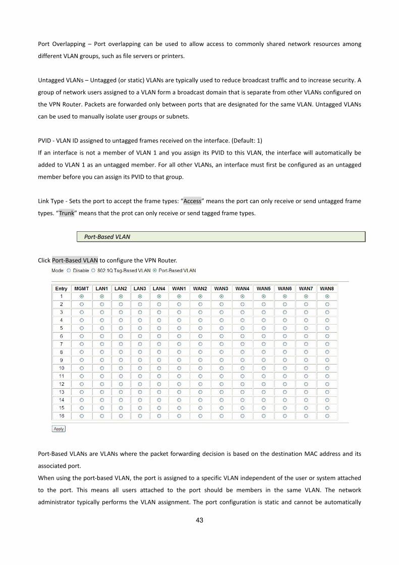
PPoorrtt--BBaasseedd VVLLAANN
Click Port-Based VLAN to configure the VPN Router.
Port-Based VLANs are VLANs where the packet forwarding decision is based on the destination MAC address and its
associated port.
When using the port-based VLAN, the port is assigned to a specific VLAN independent of the user or system attached
to the port. This means all users attached to the port should be members in the same VLAN. The network
administrator typically performs the VLAN assignment. The port configuration is static and cannot be automatically

44
changed to another VLAN without manual reconfiguration.
As with other VLAN approaches, the packets forwarded using this method do not leak into other VLAN domains on the
network. After a port has been assigned to a VLAN, the port cannot send to or receive from devices in another VLAN.
For example,
The default setting is all ports connected which means all ports can communicate with each other. That is, there are
no virtual LANs. The option is the most flexible but the least secure.
33..55..33.. QQ--iinn--QQ
VPN router allows users to setup Q-in-Q function in 4 modes.
1. Disable
2. Mapping
3. By VLAN
4. By WAN

45
MMaappppiinngg
Total of 16 rules are allowed for users to setup.
BByy VVLLAANN

46
BByy WWAANN

47
33..55..44.. SSwwiittcchh
“Switch” function allows users to setup each LAN port individually. 5 options are available for a LAN port.
1. Auto
2. 100M/Full
3. 100M/Half
4. 10M/Full
5. 10M/Half
33..55..55.. SSttaattiicc RRoouuttee
A static route is one that is manually installed by your network administrator. This is a very efficient way to transfer
data from one subnet to another despite the fact that this type of route is manually intensive.
Static route is a path in the router that indicates how it will reach a certain subnet by taking a specific path.

48
The opposite of a static route is a dynamic route. Dynamic routes are created by routing protocols.
Static routes have advantages and disadvantages as compares to dynamic routes.
Advantages of Static Routes
Static routes are easier to configure
No need for overhead on the routing protocol
As long as you have a tight IP mask, this offers you reliable security
Disadvantages of Static Routes
In order to make changes in the network, you have to manually configure the route
When network outage is experienced, it does not automatically route around
Although this is quite easy to configure, it might not work for large and complicated networks
It is important that any network administrator have substantial knowledge about static routes. Although this type of
route may not be as effective with large networks, they are quite useful in any size of networks. Meanwhile, even if
you have setup a dynamic route, there are cases that still require a static route.
33..55..66.. QQooSS
QoS(Quality of Service) refers to both a network’s ability to deliver data with minimum delay, and the networking
methods used to control the use of bandwidth. Without QoS, all traffic date is equally likely to be dropped when the
network is congested. This can cause a reduction in network performance and mark the network inadequate for
time-critical application such as video-on-demand.
QoS (Quality of Service) is to decide which PCs can get the priorities to pass though VPN Router once if the bandwidth
is exhausted or fully saturated.
49
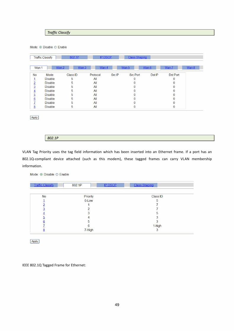
TTrraaffffiicc CCllaassssiiffyy
880022..11PP
VLAN Tag Priority uses the tag field information which has been inserted into an Ethernet frame. If a port has an
802.1Q-compliant device attached (such as this modem), these tagged frames can carry VLAN membership
information.
IEEE 802.1Q Tagged Frame for Ethernet:

50
User priority is giving eight ( 23 = 8 ) priority levels. The default value is 0, indicating normal treatment.
Priority Level Traffic Type
0 (default) Best Effort
1 Background
2 Spare
3 Excellent Effort
4 Controlled Load
5 Video, less than 100 milliseconds latency and jitter
6 Voice, less than 10 milliseconds latency and jitter
7 Network Control
Each Priority level can be set queue from 0 to 3.
Scheduling Configuration item can setup the type is from 1 to 3. Queue from 0 to 3 can set up their Queue
Weight form 1 to 15.
IIPP DDSSCCPP
Differentiated Services (DiffServ) is a class of service(CoS) model that enhances best-effort Internet services by
differentiating traffic by users, service requirements and other criteria. Packet are specifically marked, allowing
network nodes to provide different levels of service, as appropriate for video playback, voice calls or other
delay-sensitive applications, via priority queuing or bandwidth allocation.
DiffServ defines a new DS(Differentiated Services) field to replace the Type of Service(ToS) field in the IP header. The DS
field contains a 2-bits unused field and 6-bits DSCP field which can define up to 64 service levels.

51
The following figure illustrates the DS field:
The DSCP value used to identify 64 levels (26=64) of service determines the forwarding behavior that each packet gets
across the DiffServ network. Based on the marking rule different kinds of traffic can be marked for different priorities
of forwarding. Resources can then be allocated according to the DSCP values and the configured policies.
The following is an illustration about how the bits are used in DSCP field.
Bit 0 Bit 1 Bit 2 Precedence Usage
1 1 1 7 Stays the same(link layer and routing protocol keep
alive)
1 1 0 6 Stays the same(used for IP routing Protocols)
1 0 1 5 Express Forwarding (EF)
1 0 0 4 Class 4
0 1 1 3 Class 3
0 1 0 2 Class 2
0 0 1 1 Class 1
0 0 0 0 Best effort
Bit 3 Bit 4 Bit 5 Usage Meaning
0 -- -- Delay Normal
1 -- -- Delay Low
-- 0 -- Throughput Normal
-- 1 -- Throughput High

52
-- -- 0 Reliability Normal
-- -- 1 Reliability High
The standardized DiffServ field of the packet is marked with a value so that the packet receives a particular forwarding
treatment at each network node.
RFC 2597 defines the assured forwarding (AF) classes. There are four AF classes, AF1x through AF4x. Within each class,
there are three drop probabilities. Depending on a given network's policy, packets can be selected for a PHB based on
required throughput, delay, jitter, loss, or according to priority of access to network services.
Classes 1 through 4 are referred to as AF classes.
The following table illustrates the DSCP coding for specifying the AF class with the probability. Bits 0, 1, and 2 define
the class; bits 3 and 4 specify the drop probability; bit 5 is always 0.
Class 1 Class 2 Class 3 Class 4
Low Drop
001010
AF11
DSCP 10
010010
AF21
DSCP 18
011010
AF31
DSCP 26
100010
AF41
DSCP 34
Medium Drop
001100
AF12
DSCP 12
010100
AF22
DSCP 20
011100
AF32
DSCP 28
100100
AF42
DSCP 36
High Drop
001110
AF13
DSCP 14
010110
AF23
DSCP 22
011110
AF33
DSCP 30
100110
AF43
DSCP 38
The recommended DSCP values which are based on RFC 4594 are in the following table:
Service Class Name DSCP Name DSCP Value Application Examples
Network Control and
OAM
CS6 110000 (48) Network routing and OAM (e.g. SNMP, Ethernet
CFM, proprietary NMS traffic)
Signaling CS5 101000 (40) Signaling (e.g. H.323, SIP)
Telephony EF 101110 (46) IP Telephony bearer
Multimedia
Conferencing
AF41, AF42,
AF43
100010 (34), 100100 (36),
100110(38)
Videoconferencing
Real-Time Interactive CS4 100000 (32) Interactive control (e.g. CAM), real-time
e-learning, games, e-arts
Multimedia Streaming AF31,AF32,
AF33
011010 (26), 011100 (28),
011110 (30)
Streaming video and audio on demand
Broadcast Video CS3 011000 (24) Broadcast TV & live events

53
Low-Latency Data AF21,AF22,
AF23
010010 (18), 010100 (20),
010110 (22)
Transactional applications, database
access, interactive data applications
High-Throughput Data AF11,AF12,
AF13
001010 (10), 001100 (12),
001110 (14)
Bandwidth channels
Standard (Best Effort) DF (CS0) 000000 (0) Undifferentiated applications
Low-Priority Data
(LBE)
CS1 001000 (8) Mirror service, remote backups, etc
Each DSCP value (from 0 to 63) is mapped to a Queue value (from 1 to 8) from the drop-down list box. The number 1
represents the highest priority and number 8 represents the lowest priority and according various queuing strategies
to tailor performance to requirements. You are easy to change the table setting. If you want to save the changes, click
Apply.

54
CCllaassss SShhaappiinngg
Traffic policing can propagates bursts. When the traffic rate reaches the configured maximum rate, excess traffic is
dropped (or remarked). The result is an output rate that appears as a saw-tooth with crests and troughs. In contrast to
policing, traffic shaping retains excess packets in a queue and then schedules the excess for later transmission over
increments of time. The result of traffic shaping is a smoothed packet output rate.
33..55..77.. RRIIPP
The RIP (Routing Information Protocol) is a dynamic routing protocol used in local and wide area networks. It’s a very
simple protocol, based on distance-vector routing algorithms.
As such it is classified as an IGP (interior gateway protocol). VPN Router is support version 1 (RFC1058) and Version 2

55
(RFC2453).
It can set the specified interface (LAN, WAN1 to WAN8) to passive mode. On passive mode interface, all receiving
packets are processed as normal and rip does not send either multicast or unicast RIP packets.
33..55..88.. VViirrttuuaall SSeerrvveerr
This feature allows you to make servers on your LAN accessible to Internet users. Normally, Internet users would not
be able to access a server on your LAN because:-
(1) Your server does not have a valid external IP address.
(2) Attempts to connect to devices on your LAN are blocked by the firewall in this device IP address seen by Internet
Users
To interface users, all virtual servers on your LAN have the same IP address. The IP address is allocated by your ISP.
This address should be static, rather than dynamic, to make it easier for Interface users to connect to your Servers.
Once configured, anyone on the Internet can connect your virtual servers. They must use the Internet IP address .The
IP address allocated to you by your ISP.
It is more convenient if you are using fixed IP address from your ISP, rather than dynamic.
However, you can use the dynamic DNS feature to allow users to connect to your Virtual servers using a URL, rather
than an IP address.
TCP (Transmission Control Protocol) is a connection-oriented protocol that is responsible for reliable communication
between two end processes. The unit of data transferred is called a stream, which is simply a sequence of bytes.

56
UDP (User Datagram Protocol) offers only a minimal transport service (non-guaranteed datagram delivery) and gives
applications direct access to the datagram service of the IP layer. UDP is used by applications that do not require the
level of service of TCP or that wish to use communications services (e.g., multicast or broadcast delivery) not available
from TCP.
33..55..99.. DDMMZZ
In computer security, DMZ (demilitarized zone) is a physical or logical sub-network that contains and exposes an
organization's external services to a larger untrusted network, usually the Internet. The term is normally referred to as
a DMZ by IT professionals. It is sometimes referred to as a Perimeter Network. The purpose of a DMZ is to add an
additional layer of security to an organization's LAN (Local Area Network); an external attacker only has access to
equipment in the DMZ, rather than any other part of the network.
If enabled this feature, allows one or more computers on your LAN to be exposed to all users on the internet. You can
set a DMZ PC for each WAN IP address. If you only have 1 WAN IP address, only 1 DMZ PC can be used.
33..11..66.. DDDDNNSS
DDNS (Dynamic DNS Free) allows you to create a hostname that points to your home or office IP address, providing an
easy-to-remember URL for quick access.
You must register for the service at one of the listed service providers. You can reach the service provider’s Web Site by
selecting them in the list. Apply for a domain name, and ensure it is allocated to you.

57
Details of your DDNS account (Host name, Name, password) must then be entered and saved on this screen.
The device will then automatically ensure that you current IP address is recorded by the DDNS service provider from
the internet, users will now be able to connect to your Virtual Servers using your Domain name.
33..55..1100.. IIGGMMPP
IGMP (Internet Group Management Protocol) proxy can be used to implement multicast routing. It works by IGMP
frame forwarding. VPN Router’s IGMP proxy supports IGMP version 2 (RFC2236).
IGMP proxy enables the system to issue IGMP host messages on behalf of hosts that the system discovered through
standard IGMP interfaces. The system acts as a proxy for its hosts.
IGMP snooping is the process of listening to IGMP network traffic. IGMP snooping, as implied by the name, is a feature
that allows VPN Router to "listen in" on the IGMP conversation between hosts to this VPN Router by processing the
IGMP packets sent in a multicast network.
When IGMP snooping is enabled, VPN router will analyzes all IGMP packets between hosts connected to the VPN
router and multicast routers in the network. When the VPN router hears an IGMP report from remote side for a given
multicast group, the VPN router adds the host's port number to the multicast list for that group. And, when the VPN
Router hears an IGMP leave, it removes the host's port from the table entry.
33..66.. SSeeccuurriittyy
33..66..11.. FFiirreewwaallll
A firewall is a set of related programs that protects the resources of a private network from other networks. It is
helpful to users that allow preventing hackers to access its own private data resource accidentally.
There have three security levels for setting: Basic firewall security, Automatic firewall security and advanced firewall
security.

58
X’mas tree scan: It can send a TCP frame to a remote device with the URG, PUSH, and FIN flags set. This is called a
Xmas tree scan because of the alternating bits turned on and off in the flags byte, much like the lights of a Christmas
tree.
Null scan: The null scan turns off all flags, creating a lack of TCP flags that should never occur in the real world.
SYN flood: A SYN flood is a form of denial-of-service attack, attempts to slow your network by requesting new
connections but not completing the process to open the connection. Once the buffer for these pending connections is
full a server will not accept any more connections and will be unresponsive.
ICMP flood: A sender transmits a volume of ICMP request packets to cause all CPU resources to be consumed serving
the phony requests.
UDP Flood: A UDP flood attack is a denial-of-service (DoS) attack using the User Datagram Protocol(UDP). A sender
transmits a volume of requests for UDP diagnostic services which cause all CPU resources to be consumed serving the
phony requests.
Ping of Death: A ping of death (POD) attack attempts to crash your system by sending a fragmented packet, when
reconstructed is larger than the maximum allowable size.
Land attack: A land attack is an attempt to slow your network down by sending a packet with identical source and
destination addresses originating from your network.
IP Spoofing: IP Spoofing is a method of masking the identity of an intrusion by making it appeared that the traffic came
from a different computer. This is used by intruders to keep their anonymity and can be used in a Denial of Service

59
attack.
Smurf attack: The Smurf attack is a way of generating a lot of computer network traffic to a victim host. That is a type
of denial-of-service attack. A Smurf attack involves two systems. The attacker sends a packet containing a ICMP echo
request (ping) to the network address of one system. This system is known as the amplifier. The return address of the
ping has been faked (spoofed) to appear to come from a machine on another network (the victim). The victim is then
flooded with responses to the ping. As many responses are generated for only one attack, the attacker is able use
many amplifiers on the same victim.
Fraggle attack: A Fraggle attack is a type of denial-of-service attack where an attacker sends a large amount of UDP
echo traffic to IP broadcast addresses, all of it having a fake source address. This is a simple rewrite of the smurf attack
code.

60
33..66..22.. VVPPNN
A VPN (Virtual Private Network) provides a secure connection between 2 points, over an insecure network. The Secure
is called a VPN Tunnel.
The VPN Router supports three main type of VPN: IPsec, L2TP and PPTP.
IIPPsseecc
IPsec is a near-ubiquitous VPN security standard, designed for use with TCP/IP networks. It works at the packet level,
and authenticates and encrypts all packets traveling over the VPN Tunnel. Thus, it does not matter what applications
are used on your PC. Any application can use the VPN like any other network connection.
IPsec VPNs exchange information through logical connections called SAs(Security Associations). An SA is simply a
definition of the protocols, algorithms and keys used between the two VPN devices(endpoints)
There are two security modes possible with IPsec:
Transport Mode – the payload (data) part of the packet is encapsulated through encryption but the IP header remains
in the clear (unchanged)
Tunnel Mode – everything is encapsulated including the original IP header, and a new IP header is generated. Only the
new header in the clear (i.e. not protected). This system provides enhanced security.
IKE(Interface Key Exchange) is an optional, but widely used, component of IPsec.
IKE provides a method of negotiating and generating the keys and IDs required by IPsec. If using IKE, only a single key is
required to be provided during configuration. Also, IKE supports using Certificates to authenticate the identify of the
remote user or gateway.
If IKE is not used, then all keys and IDs(SPIs) must be entered manually, and Certificates can’t be used, This is called a
“Manual Key Exchange”.

61
Enable
This indicates whether or not the policy is currently enabled. Use the Enable/Disable to toggle the state the selected
policy.
Policy name
The name of the policy. When creating a policy, you should select a suitable name.

62
Example: Configuring a IPSec LAN-to-LAN VPN Connection
Network Configuration and Security Plan
Branch Office Head Office
Local Network ID 192.168.0.0/24 192.168.1.0/24
Local Router IP 69.1.121.30 69.1.121.3
Remote Network ID 192.168.1.0/24 192.168.0.0/24
Remote Router IP 69.1.121.3 69.1.121.30
IKE Pre-shared Key 12345678 12345678
VPN Connection Type Tunnel mode Tunnel mode
Security Algorithm ESP:MD5 with AES ESP:MD5 with AES
Both office LAN networks must in different subnet with LAN to LAN application.
Functions of Pre-shared Key, VPN Connection, type and Security Algorithm must be identically set up on both sides.

63
Example: Configuring a IPSec Host-to-LAN VPN Connection
LL22TTPP
L2TP (Layer 2 Tunneling Protocol) is a tunneling protocol used to support VPNs. It doesn’t provide any encryption or
confidentiality by itself; it relies on an encryption protocol that it passes within the tunnel to provide privacy.
L2TP allows a PPP session to travel over multiple links and networks. PPP is used to encapsulate IP packets from the
user's PC or mobile device to the ISP, and L2TP extends that session across the Internet.
Example: Configuring L2TP LAN-to-LAN VPN Connection
The branch office establishes a L2TP VPN tunnel with head office to connect two private networks over the Internet.
The routers are installed in the head office and branch office accordingly.

64
Both office LAN networks must in different subnet with LAN to LAN application.
Functions of Pre-shared Key, VPN Connection Type and Security Algorithm must be identically set up on both sides.
PPPPTTPP
PPTP( Point-to-Point Tunneling Protocol)is a private network of computers that uses the public Internet to connect
some nodes. Because the Internet is essentially an open network, the PPTP is used to ensure that messages
transmitted from one VPN node to another are secure. With PPTP, users can dial in to their corporate network via the
Internet.
There are two types of PPTP VPN supported; Remote Access and LAN-to-LAN.

65
Example: Configuring a Remote Access PPTP VPN Dial-out Connection
A company’s office establishes a PPTP VPN connection with a file server located at a separate location. The router is
installed in the office, connected to a couple of PCs and Servers.
Example: Configuring a PPTP LAN-to-LAN VPN Connection
The branch office establishes a PPTP VPN tunnel with head office to connect two private networks over the Internet.
The routers are installed in the head office and branch office accordingly.
Both office LAN networks MUST in different subnet with LAN to LAN application.

66
Configuring PPTP VPN in the Head Office
The IP address 192.168.1.254 will be assigned to the router located in the branch office. Please make sure this IP is not
used in the head office LAN.
Configuring PPTP VPN in the Branch Office
The IP address 69.1.121.33 is the Public IP address of the router located in head office. If you registered the DDNS
(please refer to the DDNS section of this manual), you can also use the domain name instead of the IP address to
reach the router.
VPN Configuration
VPN Endpoint address
Each VPN endpoint must be configured to initiate or accept connections to the remote VPN client gateway. Usually,
this requires having a fixed Internet IP address. However, it possible for a VPN gateway to accept incoming connections
from a possible for remote client where the client’s IP address is not known in advance.
If connecting 2 LANs, this requires that:
Each endpoint must be aware of the IP address used on the other endpoint.
The 2 LANs must use different IP address ranges.
VPN Pass-through
Here, a PC on the LAN behind the VPN router is using VPN software, but the VPN router is not acting as CPN endpoint,
It is only allowing the VPN connection.
The PC software can use any VPN protocol supported by the remote VPN.
The remote VPN server must support client PCs which are behind a NAT router, and so have an IP address which is not
valid on the Internet.
The VPN router requires no VPN configuration, since it is not acting as a VPN endpoint.
Client PC to VPN Gateway
Here, the PC must run appropriate VPN client software in order to connect, via the Internet to VPN router. Once
connected, the client PC has same access to LAN resources as PCs on the local LAN.
Connecting 2 VPN gateways
This allows two LANs to be connected PCs on each endpoint gain secure access to the remote LAN.
The 2 LANs must use different IP address ranges.
The VPN policies at each end determine when a VPN tunnel will be established, and what system on the remote LAN
can be accessed once the VPN connection is established.
It is possible to have simultaneous VPN connections to many remote sites.

67
Remote VPN Endpoint
The IP address of the remote VPN end point (Gateway or client)
33..66..33.. FFiilltteerr
IIPP ffiilltteerr
Source IP Address(es) / Destination IP Address(es): This is the Address-Filter used to allow or block traffic to/from

68
particular IP address(es). Selecting the Subnet Mask of the IP address range you wish to allow/block the traffic to or
form; set IP address and Subnet Mask to 0.0.0.0 to inactive the Address-Filter rule.
Protocol: It is the packet protocol type used by the application, select among from TCP or UDP or both of TCP/UDP.
Source Port: This Port or Port Ranges defines the port allowed to be used by the Remote/WAN to connect to the
application. Default is set from range 0 ~ 65535. It is recommended that this option be configured by an advanced
user.
Destination Port: This is the Port or Port Ranges that defines the application.
Application Protocol Port Number
Start End
HTTP TCP 80 80
DNS UDP 53 53
DNS TCP 53 53
FTP TCP 21 21
Telnet TCP 23 23
SMTP TCP 25 25
POP3 TCP 110 110
NEWS(NNTP) TCP 119 119
Real Audio/ Real Video UDP 7070 7070
PING ICMP N/A N/A
H.323 TCP 1720 1720
T.120 TCP 1503 1503
SSH TCP 22 22
NTP /SNTP UDP 123 123
HTTP/HTTP Proxy TCP 8080 8080
HTTPS TCP 443 443
ICQ TCP 5190 5190
MSN(1863) TCP 1863 1863
MSN(7001) UDP 7001 7001
MSB video TCP 9000 9000

69
MMAACC ffiilltteerr
In computer networking, MAC Filtering refers to a security access control methodology whereby the 48-bit
address(XX:XX:XX:XX:XX:XX) assigned to each network device is used to determine access to the network.
MAC addresses are uniquely assigned to each network device, so using MAC filtering on a network permits and denies
network access to specific devices through the use of black lists and white lists. While the restriction of network
access through the use of lists is straightforward, an individual person is not identified by a MAC address, rather a
device only, so an authorized person will need to have a white list entry for each device that he would use to access
the network.
While giving a wireless network some additional protection, MAC Filtering can be circumvented by scanning a valid
MAC and then changing the own MAC into a validated one.

70
33..77 MMaannaaggeemmeenntt
33..77..11.. SSNNTTPP
Time synchronization is an essential element for any business, which relies on the IT system. The reason for this is that
these systems all have clock that is the source of timer for their filing or operations. Without time synchronization,
these system’s clocks vary and cause the failure of firewall packet filtering schedule processes, compromised security,
or virtual server working in wrong schedule.
SNTP is the acronym for Simple Network Time Protocol, which is an adaptation of the Network Time Protocol (NTP)
used to synchronize computer clocks in the Internet. SNTP can be used when the ultimate performance of the full NTP
implementation. The function only supported on router mode.
There are two methods to synchronize time, synchronize with PC or SNTP. If you choose synchronize with PC, the VPN
Router will synchronize with PC’s internal timer. If you choose SNTP, the VPN Router will use the protocol to
synchronize with the time server. For synchronization the time server with SNTP, needs to configure service,
time_server and time_zone. For synchronization with PC, doesn’t need to configure the above parameters.
SSyynncc wwiitthh PPCC
Synchronize with PC, the VPN Router will synchronize with PC’s internal timer.
SSNNTTPP

71
Service: Enable
Time Server 1, Time Server 2 and Time Server 3: All of the time server around the world can be used but suggest using
the time server nearby to your country. You can set up maximum three time server on here.
Time Zone: Select the time difference between UTC(Universal Time Coordinated, formerly known as GMT, Greenwich
Mean Time) and your time zone from the drop-down list box.
33..77..22.. SSNNMMPP
Simple Network Management Protocol (SNMP) provides for the exchange of messages between a network
management client and a network management agent for remote management of network nodes. These messages
contain requests to get and set variables that exist in network nodes in order to obtain statistics, set configuration
parameters, and monitor network events. SNMP communications can occur over the LAN or WAN connection.
The router can generate SNMP traps to indicate alarm conditions, and it relies on SNMP community strings to
implement SNMP security.
This router support both MIB I and MIB II.
GGeenneerraall
SSNNMMPPvv33

72
TTrraapp
3.7.3. TTRR--006699
TR-069 (short for Technical Report 069) is a DSL Forum technical specification entitled CPE WAN Management
Protocol (CWMP). It defines an application layer protocol for remote management of end-user devices.
As a bidirectional HTTP based protocol it provides the communication between CPE (customer premises equipment)
and ACS (Auto Configuration Servers). It includes both a safe auto configuration and the control of other CPE
management functions within an integrated framework. Using TR-069 the terminals can get in contact with the ACS
(Auto Configuration Servers) and establish the configuration automatically.
ACS URL
URL for the CPE to connect to the ACS using the CPE WAN Management Protocol. This parameter MUST be in the form
of a valid HTTP or HTTPs URL. An HTTPs URL indicates that the ACS supports SSL. The “host” portion of this URL is used

73
by the CPE for validating the certificate from the ACS when using certificate-based authentication.
ACS User Name
Username used to authenticate the CPE when making a connection to the ACS using the CPE WAN Management
Protocol. This username is used only for HTTP-based authentication of the CPE.
ACS Password
Password used to authenticate the CPE when making a connection to the ACS using the CPE WAN Management
Protocol. This password is used only for HTTP-based authentication of the CPE.
Periodic Inform Interval
The duration in seconds of the interval, for which the CPE must attempt to connect with the ACS and call the Inform
method.
Connection Request Username
Username used to authenticate an ACS making a Connection Request to the CPE.
Connection Request Password
Password used to authenticate an ACS making a Connection Request to the CPE.
33..77..44.. UUPPnnPP
Enable UPnP(Universal Plug and Play) allow automatic discovery and configuration of equipment attached to your LAN.
UPnP is supported by Windows ME, XP or later.
If Enabled, this VPN Router will be visible via UPnP
If Disabled, this VPN Router will not be visible via UPnP
Press Apply to finish the setup.
33..77..55.. SSyyss LLoogg

74
Syslog is a standard method of centralizing various logs. You can use a syslog server to store your servers logs in a
remote location for later perusal or long-term storage.
To send logs to the LOG server, you must configure the other servers from your network to send logs to that server.
1. Click the enable item of Syslog Server Service to turn on syslog service.
2. Input the syslog remote server address. The remote server address allows you to send logs to different files in the
syslog server.
3. Specify a UDP port number to which the syslog server is listening. The default value is 514.
Make sure this is not blocked from your firewall.
Press Apply to finish the setup.
33..77..66.. TTeellnneett
There are quite a few Telnet clients available, many of which are free. For example, the Windows operating systems
are shipped with a Telnet client included (found at "c:\windows\telnet.exe"). This Telnet client is simple and functional.
For Telnet, you may change the default service port by typing the new port number. If you change the default port
number then you will have to let user who wish to use the service know the new port number. The default value is 23.
Press Apply to finish the setup.
33..77..77.. SSSSHH

75
SSH (or Secure Shell) is a protocol that can be used to log into a remote machine (your Virtual Server) and provide
secure encrypted communications between your VON Router and your local computer. All of the commands you would
use in a Telnet client, you can use in an SSH client. The only difference is that the communication is made via encrypted
channels to and from your VPN Router.
Once you have chosen a SSH (or Telnet) client, connecting to your Virtual Server is extremely simple. Although SSH
(and Telnet) clients vary in their exact configuration, most of them will simply require you to specify a "remote host".
Your remote host is your VPN Router, so you would specify your domain name (or your temporary domain, if
applicable) or IP address.
Once you are connected, you will be prompted for your login name and login password. You specified both your login
name and login password when you ordered your VPN Router. After the login process is successful, you will have
gained access to your VPN Router and can now issue commands at the command prompt.
For SSH, you may change the default service port by typing the new port number. If you change the default port
number then you will have to let user who wish to use the service know the new port number. The default value is 22.
Press Apply to finish the setup.
33..77..88.. WWeebb
It can re-fresh web pages when you are viewing your dynamic status data pages. You can setup the refresh time from 2
to 30 seconds. The default value is 2 seconds.
For Web Browser, you may change the default service port by typing the new port number. If you change the default
port number then you will have to let user who wish to use the service know the new port number. The default value
is 80.
Press Apply to finish the setup.
33..88 SShhooww

76
33..88..11.. IInnffoorrmmaattiioonn
There will display general system information including: Hardware and Software MCSV, software version, chipset,
firmware version, Host Name, System Time and System Up Time.
MCSV: MCSV is the Manufacture's Concurrent Software Version. This version is the original factory version and
remains even after upgrading the router in the field. This is for internal identification purposes.
Software Version: This is the modem’s current firmware version. This is sometimes needed by technicians to help
troubleshoot problems.
Chipset Name: This is the G.SHDSL chipset’s name.
Firmware Version: This is the chipset’s firmware version.
Present Time: This field display your VPN Router’s present date and time.
System Up Time: This is the total time on the VPN Router has been on.

77
33..88..22.. SSyyss LLoogg
33..88..33.. CCPPUU IInnffoo

78
33..88..44.. SSccrriipptt

79
33..99 SSttaattuuss
33..99..11.. SSHHDDSSLL
For 2-wire models:
For 4-wire models:
For 8-wire models:

80
If the VPN router have connected to remote side, it can also show the performance information of remote side.
Click Clear CRC can clear the CRC error count.
33..99..22.. WWAANN
This information shows all eight WAN interface.
33..99..33.. RRoouuttee TTaabbllee
Routing tables contain a list of IP address. Each IP address identifies a remote router (or other network gateway) that
the local router is configured to recognize. For each IP address, the routing table additionally stores a network mask
and other data that specifies the destination IP address ranges that remote device will accept.

81
33..99..44.. IInntteerrffaacceess
This table shows the interface statistics.
Octet is a group of 8 bits, often referred to as a byte.
Packet is a formatted block of data carried by a packet mode computer networks, often referred to the IP packet.
InOctets The field shows the number of received bytes on this port
InPactets The field shows the number of received packets on this port
OutOctets The field shows the number of transmitted bytes on this port
OutPactets The field shows the number of transmitted packets on this port
InDrops The field shows the discarded number of received packets on this port
OutDrops The field shows the discarded number of transmitted packets on this port
33..99..55.. SSTTPP

82
33..99..66.. SSwwiittcchh

83
33..1100 UUttiilliittiieess
33..1100..11.. UUppggrraaddee
Upgrade Firmware
Click the “Browser” button and browse to the location on your PC where you stored the firmware upgrade.
Select the upgrade file. There name will appear in the Upgrade file field.
Click the “Upgrade” button to commence the firmware upgrade.
33..1100..22.. CCoonnffiigg TTooooll
This configuration tool has three functions: load Factory Default, Restore Configuration, and Backup Configuration.
LLooaadd FFaaccttoorryy DDeeffaauulltt
Load Factory Default: It will load the factory default parameters to the router.
Note: This action will change all of the settings to factory default value. On
the other hand, you will lose all the existing configured parameters.
BBaacckkuupp CCoonnffiigguurraattiioonn

84
After configuration, suggest using the function to backup your router parameters in the PC. Select the Backup
Configuration and then press Apply. Browse the place of backup file name or put the name. Then press OK. The router
will automatically backup the configuration. If you don’t put the file name, the system will use the default: config1.log

85
RReessttoorree CCoonnffiigguurraattiioonn
Sometime the configuration crushed occasionally. It will help you to recover the backup configuration easily.
Click Apply after selecting Restore Configuration.
Browse the route of backup file then press Apply. Brower the place of restore file name or put the name. Then press
OK. The router will automatically restore the saved configuration.
33..1100..33.. UUsseerrss
For greater security, change the Administrator Name and password for the VPN router. If you don’t set them, all users
on your network can be able to access your VPN router using the default Administrator Name and password is “root”.
You can authorize other four legal users to access the VPN Router via Web, telnet or console. There has CLI (command
line) mode for telnet or console mode to setup the VPN Router.
We will not discuss CLI (command line) mode in this manual.
Legal address pool will setup the legal IP addresses from which authorized person can configure the router. This is the
more secure function for network administrator to setup the legal address of configuration.

86
Level
Administrator
Normal
Guest
This is the default administrator ID and password is “root”. It is highly recommended that you change these for security
purpose.
Name: Type the new User Name (“root” is the default name when shipped)
Level: Administrator, Normal and Guest
Password: Type the existing password (“root” is the default password when shipped)
Password Confirm: Retype your new password for confirmation.
Click Apply to finish the setting.
33..1100..44.. PPiinngg
Ping test determines whether your VPN router can communicate with another computer or other web sites over the
network. Then, if network communication is established, ping tests also determine the connection latency (technical
term for delay) between the two device. You can use a ping test to troubleshoot connectivity problems with your
home network. Ping tests are also commonly used to measure the delay ("lag") with some Internet servers.
To execute a ping test, you simply identify the Web site or other remote server / computer by its IP address. The result
of a ping test includes confirmation that connection was successful, along with a series of numbers that represent the
communication delay in milliseconds (ms).
Ping reports the percentage of packets acknowledged by the remote host. Typically this number will be 100% (as in the
example above) or 0%. When an Internet host pings at 0%, this does not necessarily mean the server is "down" or
unavailable. Internet Web servers especially may be configured to disregard ping requests for security purposes.
The results of a ping test vary depending on the quality of the Internet / network connection. A good broadband
Internet connection typically results in ping test latency of less than 100 ms, often less than 30ms. A satellite Internet
connection normally suffers from latency above 500ms.
On intranets and other private LANs, ping can be an especially useful network diagnostic tool. One scenario that will
result in a ping response rate of other than 0% or 100% occurs when a host is shutdown and leaves the network (or
boots and joins the network).

87
It is also possible for ping packets to be lost in transit, causing ping to report a host as unavailable when in fact it is
available but unreachable. One cause of lost or dropped packets is extreme levels of traffic. In general, ping utilities will
be unusable on heavily-loaded networks.
IP Address : Which IP address you want to ping
Size : Size of byte packets to the destination, default is 56
Count : Ping count number, default is 3
Update : Updated time, default is 2
33..1100..55.. TTrraaccee RRoouuttee
The trace route command traces the network path of Internet routers that packets take as they are forwarded from
your VPN router to a destination address. The "length" of the network connection is indicated by the number of
Internet routers in the trace route path.
Trace routes can be useful to diagnose slow network connections. For example, if you can usually reach an Internet
site but it is slow today, then a trace route to that site should show you one or more hops with either long times or
marked with "*" indicating the time was really long. If so, the blockage could be anywhere from your Internet service
provider to a backbone provider, and there is likely little you can do except wait with the infinite patience of the
mighty oak.
Host name or IP: Type which Host name and IP address you want to ping.
Update Interval: Set the amount of seconds to wait for an answer from each host before giving up, default of 2

88
44 TTeerrmmiinnoollooggyy
Abbrev. Full Term Meaning
EoA Ethernet-over-ATM EoA protocol is commonly used to carry data
between local area networks that use the Ethernet
protocol and wide-area networks that use the ATM
protocol. Many telecommunications industry
networks use the ATM protocol. ISPs who provide
DSL services often use the EoA protocol for data
transfer with their customers' DSL modems.
VPI Virtual Path Identifier for set up ATM Permanent Virtual Channels(PVC).
VCI Virtual Channel Identifier for set up ATM Permanent Virtual Channels(PVC).
EoA
EoA (Ethernet-over-ATM) protocol is commonly used to carry data between local area networks that use the Ethernet
protocol and wide-area networks that use the ATM protocol. Many telecommunications industry networks use the
ATM protocol. ISPs who provide DSL services often use the EoA protocol for data transfer with their customers' DSL
modems.
EoA can be implemented to provide a bridged connection between a DSL modem and the ISP. In a bridged connection,
data is shared between the ISP's network and their customer's as if the networks were on the same physical LAN.
Bridged connections do not use the IP protocol. EoA can also be configured to provide a routed connection with the
ISP, which uses the IP protocol to exchange data.
IPoA
IPoA (Dynamic IP over ATM) interfaces carries IP packets over AAL5. AAL5 provides the IP hosts
on the same network with the data link layer for communications. In addition, to allow these
hosts to communicate on the same ATM networks, IP packets must be tuned somewhat. AS the
bearer network of IP services, ATM provides high speed point-to-point connections which
considerably improve the bandwidth performance of IP network. On the other hand, ATM
provides excellent network performance and perfect QoS.

89
PPPoA / PPPoE
PPPoA (point-to-point protocol over ATM) and PPPoE (point-to-point protocol over Ethernet) are authentication and
connection protocols used by many service providers for broadband Internet access. These are specifications for
connecting multiple computer users on an Ethernet local area network to a remote site through common customer
premises equipment, which is the telephone company's term for a modem and similar devices. PPPoE and PPPoA can
be used to office or building. Users share a common Digital Subscriber Line (DSL), cable modem, or wireless
connection to the Internet. PPPoE and PPPoA combine the Point-to-Point Protocol (PPP), commonly used in dialup
connections, with the Ethernet protocol or ATM protocol, which supports multiple users in a local area network. The
PPP protocol information is encapsulated within an Ethernet frame or ATM frame.
EoA
IPoA
PPPoA

90
PPPoE