gsg-l1 gps signal generator user's...
TRANSCRIPT

GSG-L1
GPS Signal Generator
User's Manual

GPS Signal Generator
User's Manual
REF : 4031 600 01001 ISSUE : 2.1 DATE : 6.4.2009
All information in this document is the sole and exclusive property of Pendulum Instruments and shall not be disclosed by the recipient to third parties without the prior written consent of the property owner.
www.pendulum-instruments.com
TABLE OF CONTENTS
1. INTRODUCTION .......................................................................................................... 1
1.1 Signal generator unit ......................................................................................................................1 1.2 Disclaimer ......................................................................................................................................1
2. GSG-L1 OVERVIEW .................................................................................................... 2
3. SERIAL INTERFACE PROTOCOL ........................................................................... 3
3.1 General Format of Commands .......................................................................................................3 3.2 Commands .....................................................................................................................................4
3.2.1 PLPARM set commands......................................................................................................4 3.2.2 PLPARM get commands .....................................................................................................7 3.2.3 PLDELY set command........................................................................................................8 3.2.4 PLNAVM ............................................................................................................................8 3.2.5 PLSBSQ...............................................................................................................................9 3.2.6 PLSTOR ............................................................................................................................10 3.2.7 PLRSET.............................................................................................................................10
3.3 Command acknowledgements .....................................................................................................11 3.3.1 PLPARM get acknowledgements ......................................................................................11 3.3.2 PLNAVM get acknowledgements .....................................................................................12 3.3.3 Acknowledgement fields and error codes..........................................................................12
4. QUICK SETUP GUIDE............................................................................................... 14
5. GSG-L1 CONTROL SOFTWARE............................................................................. 16
5.1 Subframe maker utility.................................................................................................................17
6. TROUBLESHOOTING ............................................................................................... 19
APPENDIX A. TECHNICAL SPECIFICATIONS..................................................... 20

GPS Signal Generator
User's Manual
REF : 4031 600 01001 ISSUE : 2.1 DATE : 6.4.2009 PAGE : 1
All information in this document is the sole and exclusive property of Pendulum Instruments and shall not be disclosed by the recipient to third parties without the prior written consent of the property owner.
www.pendulum-instruments.com
1. INTRODUCTION This document presents the User’s manual for the GSG-L1 signal generator. Chapter 2 gives an overview of the signal generator. Chapter 3 presents the serial interface protocol. Chapter 4 gives a quick setup guide. Chapter 5 presents the configuration software that is shipped with the signal generator. Chapter 6 gives some guidance to technical troubleshooting. The technical specification for the signal generator is presented in appendix A.
1.1 Signal generator unit
Each signal generator package contains:
• GSG-L1 signal generator
• Power and serial cable (LEMO connectors)
• Null-modem serial cable
• A power adapter for the signal generator (9 VDC)
• Antenna cable RG-58 (SMA/SMA)
• A GPS antenna (optional)
• SMA-to-BNC adapter for the antenna cable (optional)
1.2 Disclaimer
The user must read this manual before using the signal generator. The signal generator must not be connected to the antenna without proper permissions from the relevant authorities. The user must take all other necessary actions to ensure that the generated signal does not cause any harm or interference to any GNSS users.

GPS Signal Generator
User's Manual
REF : 4031 600 01001 ISSUE : 2.1 DATE : 6.4.2009 PAGE : 2
All information in this document is the sole and exclusive property of Pendulum Instruments and shall not be disclosed by the recipient to third parties without the prior written consent of the property owner.
www.pendulum-instruments.com
2. GSG-L1 OVERVIEW The GSG-L1 is a GPS signal generator that emulates a single GPS L1 signal. Thanks to the calibrated RF level range from –70 to –150 dBm, with 0.05 dB control resolution, the sensitivity of all types of GPS receivers can be verified with a minimum of delay (<30 seconds on test line). The GSG-L1 GPS Signal Generator generates an RF-signal, an L1 carrier that is BPSK modulated with the C/A code and navigation signal. The navigation data is transferred to the GSG-L1 via the RS232 interface port from a host computer SW. A PC control program is supplied with the product. The test signal is air-to-air.
Key Features
o Very accurate one-channel GPS signal generator
o Ideal for GPS receiver production test purposes
o Wide RF output power range enables both conducted and air-to-air testing
o Fully programmable with easy to use I/O protocol
o Affordable

GPS Signal Generator
User's Manual
REF : 4031 600 01001 ISSUE : 2.1 DATE : 6.4.2009 PAGE : 3
All information in this document is the sole and exclusive property of Pendulum Instruments and shall not be disclosed by the recipient to third parties without the prior written consent of the property owner.
www.pendulum-instruments.com
3. SERIAL INTERFACE PROTOCOL The embedded software handles the interface towards the controller and controls the hardware.
The serial communication parameters are 8 data bits, no parity, one stop bit and 9600 baud. The communication uses LF, linefeeds, as line terminators and when communicating with the signal generator using a terminal software the terminal settings must hence be set to use LF, or CR+LF, as the line terminator sequence. The provided GSG-L1 configuration software automatically configures the serial port.
When connecting the signal generator to the serial port of a PC a null-modem cable, also known as a cross over cable, should be used.
NOTE! When the signal generator is switched on, please allow 20 seconds for the unit to boot before sending commands to the signal generator.
3.1 General Format of Commands
The general format for the signal generator command is as follows: ?<keyword><prn_number>:<cmd_number>:<value>*<checksum> $<keyword><prn_number>:<cmd_number>:<value>*<checksum>
Commands starting with a ‘?’ are get commands. Commands starting with ‘$’ are set commands. A signal generator command consists of different fields indicated by <keyword>, <prn_number>, <cmd_number>, <value> and <checksum>. The ‘:’ and ‘*’ symbols separate different fields of a command. The commands are terminated with a LF, linefeed.
The possible keywords are listed below.
Keyword Description PLPARM This command allows setting the registers in the HW as well
as software parameters. PLDELY Delays the code phase by a certain amount. PLNAVM Sets the navigation message PLSBSQ Resets the subframe sequence. PLRSET Resets the unit to boot loader PLSTOR Stores the current configuration to non-volatile memory PLCRLM Deletes current configuration from non-volatile memory and
resets to factory defaults

GPS Signal Generator
User's Manual
REF : 4031 600 01001 ISSUE : 2.1 DATE : 6.4.2009 PAGE : 4
All information in this document is the sole and exclusive property of Pendulum Instruments and shall not be disclosed by the recipient to third parties without the prior written consent of the property owner.
www.pendulum-instruments.com
Table 1. Signal generator commands.
The prn_number must be equal to the current PRN number of the signal generator receiving the command. The prn_number is a WORD.
The cmd_number field represents a semi-unique identity of the set command. The number is an unsigned integer represented with one BYTE, using hexadecimal representation in the serial communication. The number can be used to track acknowledgement messages to the commands set, as the same cmd_number will be used in the corresponding acknowledgement. A dummy value (e.g. “00”) can be used if command tracking is not used.
The format of the value field depends on the keyword field and on the type of the command: get or set.
Checksum must be formed and added to each command. The checksum is the two’s complement, ignoring the initial dollar sign and the asterisk sign representing the checksum field delimiter. The checksum itself is in BYTE format and thus it may rotate over the max value upon calculation.
Hexadecimal representation of numerical values is used in all communication with the signal generator. Integers used are:
• BYTE is 8bit unsigned integer
• WORD is 16bit unsigned integer
• DWORD is 32bit unsigned integer.
3.2 Commands
3.2.1 PLPARM set commands
The PLPARM set commands set software parameters as well as registers in the hardware.
The available parameters and their value ranges are shown in Table 2. The general format a PLPARM set command is holding a <parameter_id> identifier making the general syntax as below. SYNTAX: $PLPARM<prn_number>:<cmd_number>:<parameter_id>=<value>*<checksum> prn_number : WORD cmd_number : BYTE parameter_id : WORD value : DWORD checksum : BYTE

GPS Signal Generator
User's Manual
REF : 4031 600 01001 ISSUE : 2.1 DATE : 6.4.2009 PAGE : 5
All information in this document is the sole and exclusive property of Pendulum Instruments and shall not be disclosed by the recipient to third parties without the prior written consent of the property owner.
www.pendulum-instruments.com

GPS Signal Generator
User's Manual
REF : 4031 600 01001 ISSUE : 2.1 DATE : 6.4.2009 PAGE : 6
All information in this document is the sole and exclusive property of Pendulum Instruments and shall not be disclosed by the recipient to third parties without the prior written consent of the property owner.
www.pendulum-instruments.com
Parameter id Description Possible values Details
1 Frequency 0 – 0xffff This parameter adjusts the frequency over the available range.
The command should normally be used for unit calibration purposes only.
2 Doppler -5000000 - 5000000 (min.)
Sets the calibrated Doppler value in unit mHz. The default value (0) corresponds to L1 centre frequency.
3 Output power -73 - -150 (min) Sets the calibrated RF output power in dBm. The resolution is 0.05 dBm.
4 Attenuation 0 – 60 Sets the internal attenuation in dB of the unit.
The command should only be used for unit calibration purposes.
Please use the power command (parameter id = 3) for calibrated output.
5 PRN number 0 – 1023 Sets the PRN number. Supported ranges are 1–37 (GPS), 120–158 (SBAS), and 60–69 (set of non-standard codes using GPS mode). If the PRN number is outside these ranges, it is not set.
6 Z-count 0 – 0x1FF8 0000 Initiates the Z-count of the signal generator. Setting the Z-count will turn on automatic updating of Z-Count and parity. The default Z-count value is 0.
7 Update Z-count
0 – off
1 – on
Sets the automatic updating of Z-count and parity in the subframes.
8 RF Mode 0 – 5 0: RF off
1: RF on (no pulsing)
2: RF on, pulsing RTCA/DO-246B
3: RF on, pulsing RTCM-104-SC
4: Reserved
5: Un-modulated carrier

GPS Signal Generator
User's Manual
REF : 4031 600 01001 ISSUE : 2.1 DATE : 6.4.2009 PAGE : 7
All information in this document is the sole and exclusive property of Pendulum Instruments and shall not be disclosed by the recipient to third parties without the prior written consent of the property owner.
www.pendulum-instruments.com
9 Pulse length 0 – 87 Units are 1/1023. The resulting duty cycle will be (pulse-length x 11/10230).
10 Get SW version
0-0xffff ffff Software identification.
11 Get HW version
0-0xffff ffff Hardware identification number.
12 Reserved
13 RF switch 0,1 Turns On/Off RF switch with 45dB attenuation. Please use the power command (parameter id = 3) for calibrated output.
Table 2. Signal generator parameters and their values.
Note that when setting the PRN of the signal generator the prn_number in the command doesn’t have to match current PRN number used in the signal generator. This exception allows configuration the system without having to know the initial PRN number of the signal generator. In this case the PRN number can be a dummy value.
EXAMPLE: $PLPARM0001:05:0004=00000032*2e Setting the attenuation to 50dB for the PL
with PRN 1, command ID 5.
When switching to PRN number in the range 120-158 the unit will automatically switch to SBAS transmission mode. Setting a PRN number outside of this range will switch mode back to GPS. The used mode has an impact on how the navigation messages are handled. When switching mode GPS/SBAS navigation messages in use will be cleared out and the unit will use some default navigation messages depending on mode.
3.2.2 PLPARM get commands
PLPARM get commands retrieve information about the current state of the signal generator.
In these commands, the value field is a WORD, 16 bits long, and represents a parameter id. The parameter ids equals those of the PLPARM set commands (see Table 2). SYNTAX: ?PLPARM<prn_number>:<cmd_number>:<parameter_id>*<checksum> prn_number : WORD

GPS Signal Generator
User's Manual
REF : 4031 600 01001 ISSUE : 2.1 DATE : 6.4.2009 PAGE : 8
All information in this document is the sole and exclusive property of Pendulum Instruments and shall not be disclosed by the recipient to third parties without the prior written consent of the property owner.
www.pendulum-instruments.com
cmd_number : BYTE parameter_id : WORD checksum : BYTE
EXAMPLE: ?PLPARM0001:07:0004*10 Query for the attenuation settings
(parameter id 4) for the PL with PRN 1. Command ID 7.
3.2.3 PLDELY set command
The delay set command halts the PRN code generations for a specified number of processor cycles (10.23 MHz). The delay is defined by the value field, where one tick corresponds to a delay of 1/10 code chips. The command is to be used with care and will normally cause a receiver to loose track of the signal. SYNTAX: $PLDELY<prn_number>:<cmd_number>:<ticks>*<checksum> prn_number : WORD cmd_number : BYTE ticks : DWORD checksum : BYTE
3.2.4 PLNAVM set command
The PLNAVM set command updates the navigation message of the signal generator. The navigation messages are stored internally in an array holding a maximum of 250 messages / subframes, and subsequent commands will put the newly arrived message to the end of this array.
The units will transmit the received navigation messages in the same order they are sent to the unit. When the last message is transmitted the transmission will start from the beginning, transmitting the same messages in a repeated manner, however so that zcount and parity is updated accordingly.
The Z-count update (controlled using PLPARM command) assumes that the used subframe format is as specified in ICD-GPS-200C. If other formats are used then the automatic updating of Z-count should not be used. The automatic Z-count update will affect the week number (subframe 1, bits 61-70), the tow count (bits 31-47 in the hand over word for each subframe) and CRC parity fields in these subframes.
The Z-count represents the number of X1-epochs since GPS zero time point modulo-1024 weeks in a 29-bit number. The 10 MSB represents the week number and the 19 LSB represents the time of week. The modulo-20 value for the new Z-count value should equal 4. The input value will be rounded upwards

GPS Signal Generator
User's Manual
REF : 4031 600 01001 ISSUE : 2.1 DATE : 6.4.2009 PAGE : 9
All information in this document is the sole and exclusive property of Pendulum Instruments and shall not be disclosed by the recipient to third parties without the prior written consent of the property owner.
www.pendulum-instruments.com
to the nearest multiple of this. The 19 LSB must not exceed 0x626FF, which correspond to the number of epochs per week. A new Z-count value will be taken into use when the next subframe with ID 1 is to be sent. This procedure assumes that subframes are uploaded in sequence of five subframes starting with ID 1.
Use the command PLSBSQ (see below) with sequencelength = 0 to initiate the setting of the navigation message. Such a command will reset the current order and messages used.
The PLNAVM command is a simplified version of the previous PLSUBF.
SBAS
The PLNAVM command is also used for SBAS message re-transmission.
When the unit is in SBAS mode each message will be transmitted only once. Since each message is re-transmitted only once the controller software needs to provide the unit with up-to-date SBAS messages as a 1 Hz rate. The messages can be uploaded in bulks, or as continuous stream, and will be re-transmitted using a FIFO approach.
If no message has arrived in time to the next one-second time slot the Null Message Type 63 is used as a filler message. If no new messages arrive for 5 more seconds the unit will transmit MT0 until the next new message arrives.
SBAS messages should be uploaded as 250 bit messages as the unit handles the SBAS convolution encoding internally.
Preamble and checksum are updated automatically. Parity and ZCount update flags have no effect on SBAS message handling.
SYNTAX: $PLNAVM<prn_number>:<cmd_number>:<navmessage>*<checksum> prn_number : WORD cmd_number : BYTE navmessage : BIT[300] in hexadecimal representation. checksum : BYTE
3.2.5 PLNAVM get command
PLNAVM get command retrieves information about the navigation message currently in slot 0 of the signal generator. SYNTAX: ?PLPARM<prn_number>:<cmd_number>*<checksum> prn_number : WORD cmd_number : BYTE

GPS Signal Generator
User's Manual
REF : 4031 600 01001 ISSUE : 2.1 DATE : 6.4.2009 PAGE : 10
All information in this document is the sole and exclusive property of Pendulum Instruments and shall not be disclosed by the recipient to third parties without the prior written consent of the property owner.
www.pendulum-instruments.com
checksum : BYTE
EXAMPLE: ?PLNAVM0078:6c*68 Query for the SBAS message currently in
slot 0 for the PL with PRN 120.
3.2.6 PLSBSQ
Set the subframe sequence. This command defines the sequence in which the subframes are sent from the slots. The slot_nr should be in the range [0, 9].
SYNTAX: $PLSBSQ<prn_number>:<cmd_number>:<sequencelength><slot_nr>...<slot_nr>*<checksum> prn_number : WORD cmd_number : BYTE sequencelength : WORD slot_nr : BYTE checksum : BYTE
EXAMPLE: $PLSBSQ0001:07:00050001020304*08
3.2.7 PLSTOR
PLSTOR command instructs the signal generator to store its current configuration to the non-volatile memory. The signal generator will use the settings from memory at next power up. SYNTAX: $PLSTOR<prn_number>:<cmd_number>*<checksum> prn_number : WORD cmd_number : BYTE
EXAMPLE: $PLSTOR0001:0e*68
3.2.8 PLRSET
PLRSET command instructs the signal generator to reset to boot loader mode. The unit can then be set to programming mode (to upload new application software). If no commands are received within 15 seconds the unit will reload current software with default settings. SYNTAX: $PLRSET<prn_number>:<cmd_number>*<checksum>

GPS Signal Generator
User's Manual
REF : 4031 600 01001 ISSUE : 2.1 DATE : 6.4.2009 PAGE : 11
All information in this document is the sole and exclusive property of Pendulum Instruments and shall not be disclosed by the recipient to third parties without the prior written consent of the property owner.
www.pendulum-instruments.com
prn_number : WORD cmd_number : BYTE
3.2.9 PLCLRM
PLCLRM command instructs the signal generator to clear the used configuration. The unit will then reset to boot loader mode and if no commands are received within 15 seconds the unit will reload current software with factory settings. SYNTAX: $PLCLRM<prn_number>:<cmd_number>*<checksum> prn_number : WORD cmd_number : BYTE
3.3 Command acknowledgements
Each command sent to the signal generator is acknowledged. Typically, regardless of keyword used, the acknowledgement contains a positive keyword to signal that the command was processed successfully and a command identifier to help verify the original command that is being acknowledges. If the signal generator detects an error in the command, a negative acknowledgment is sent. The negative acknowledgement contains an error code specifying the reason for the error. Just like the positive message, a negative message is accompanied by a command id.
For set commands the positive acknowledgement has the general format:
!PLPACK<cmd_number>*<checksum>
EXAMPLE: !PLPACK02*07 Acknowledgement for the set command with ID 2.
A negative acknowledgement has the format:
!PLNACK<cmd_number>:<error_code>*<checksum>
EXAMPLE: !PLNACK06:04*23 This is a negative acknowledgement for the set
command with ID 6. The error code is 4, parameter value out of range.
3.3.1 PLPARM get acknowledgements
The positive acknowledgements for PLPARM get commands differ from above, since they also include information on the queried parameter, state of the signal

GPS Signal Generator
User's Manual
REF : 4031 600 01001 ISSUE : 2.1 DATE : 6.4.2009 PAGE : 12
All information in this document is the sole and exclusive property of Pendulum Instruments and shall not be disclosed by the recipient to third parties without the prior written consent of the property owner.
www.pendulum-instruments.com
generator. ‘For query commands the positive acknowledgement has the general format:
!PLPACK<cmd_number>:<value>*<checksum>
EXAMPLE: !PLPACK07:00000032*39
Acknowledgement for the query command with ID 7. The reported value, answer for the query, is hex 32 (decimal value 50).
The positive acknowledgement of a PLPARM get command contains a value field of 4 bytes (32 bits). The interpretation of these bytes is the same as the interpretation of the param_value field of the corresponding PLPARM set command. The interpretation depends on the parameter id of the PLPARM set command. These parameter ids are explained in Table 2.
3.3.2 PLNAVM get acknowledgements
The positive acknowledgement of a PLNAVM get command contains navigation data currently in slot 0 of signal generator.
3.3.3 Acknowledgement fields and error codes
The cmd_number field matches the number of the command that is being acknowledged. The command identifier will be zero if it for some reason couldn’t be acquired and hence 0 should be avoided as command identifier if command/acknowledge matching is used.
The value is an unsigned integer represented by two bytes (16 bits) in hexadecimal representation.
The checksum field is one byte (8 bits) long. It is computed as the two’s complement sum of the bytes in the value field. The checksum is ignoring the initial exclamation sign and the asterisk sign representing the checksum field delimiter.
The error_code is an unsigned integer represented by two bytes (16 bits) in hexadecimal representation. The possible error codes are:
• 0 - PL_OK, Positive acknowledgement.
• 1 - PL_ERROR_CKSUM, Wrong checksum.
• 2 - PL_ERROR_UNKNOWN_CMD, Unrecognized keyword.
• 3 - PL_ERROR_UNKNOWN_PARAM, Unrecognized parameter.
• 4 - PL_ERROR_PARAM_VALUE, Parameter value out of range.

GPS Signal Generator
User's Manual
REF : 4031 600 01001 ISSUE : 2.1 DATE : 6.4.2009 PAGE : 13
All information in this document is the sole and exclusive property of Pendulum Instruments and shall not be disclosed by the recipient to third parties without the prior written consent of the property owner.
www.pendulum-instruments.com
• 5 - PL_ERROR_PRN, Mismatch in PRN number.
• 6 - PL_ERROR_CMD, The command is not read ok, possibly the terminating new-line is missing.
• 7 - PL_ERROR_SLOT, The navigation/subframe message slot (default = 0) is not configured.
• 8 - PL_ERROR_NAVMSG, The navigation message is not acceptable, wrong format.
• 9 - PL_SYNTAX_ERROR, Syntax error in the command
• 10 - PL_ERROR_STATE, Requested operation not allowed in the current state.
• 11 - PL_ERROR_INDEX, Index out of bounds
• 12 - PL_ERROR, Default error message.

GPS Signal Generator
User's Manual
REF : 4031 600 01001 ISSUE : 2.1 DATE : 6.4.2009 PAGE : 14
All information in this document is the sole and exclusive property of Pendulum Instruments and shall not be disclosed by the recipient to third parties without the prior written consent of the property owner.
www.pendulum-instruments.com
4. QUICK SETUP GUIDE This chapter describes the steps needed to connect the GSG-L1 signal generator to a PC and monitor the signal in a GPS receiver.
The signal generator must not be connected to the antenna without proper permissions from the relevant authorities. The user must take all other necessary actions to ensure that the generated signal does not cause any harm or interference to any GNSS users.
STEP 1 – Connect the unit to PC Connect to the LEMO power cable to turn on the power. There is no separate power switch.
Connect the signal generator to the serial port of a PC. A null-modem cable, also known as a cross over cable, should be used together with the provided LEMO serial cable.
Push the LEMO connector straight in with the RED dot facing upwards – do not try to screw the connectors in!
STEP 2 – Install software Install the control software using the provided installation software (Install_GSGL1.exe). The installation software will guide you to the installation procedure and install shortcuts to the main program.
The software can be installed on Windows operating systems (2000, XP, Vista).
STEP 3 – Start software The installation program puts a link to the configuration software in the Start menu. The default location for the shortcut is: Programs Pendulum Instruments GSG-L1.
By default the installation software also puts a shortcut on the Desktop and on the Quick Launch toolbar.
STEP 4 – Connect to unit

GPS Signal Generator
User's Manual
REF : 4031 600 01001 ISSUE : 2.1 DATE : 6.4.2009 PAGE : 15
All information in this document is the sole and exclusive property of Pendulum Instruments and shall not be disclosed by the recipient to third parties without the prior written consent of the property owner.
www.pendulum-instruments.com
In the GSG-L1 configuration software, select the serial port and connect to the unit. When the connection is established the text fields are filled in with the current configuration of the unit.
When the signal generator is switched on, please allow 20 seconds for the unit to boot before connecting or sending any commands to the unit.
STEP 5 – Set parameters Adjust parameters, e.g. PRN code, according to needs. The signal strength setting depends heavily on the setup, e.g. the cable lengths and antennas used. The recommended settings below assume relatively short cables and no external attenuators.
Basic settings when using cables
• PRN: 1-32 (GPS)
• Power: -125 dBm
• Doppler: 0 Hz
• RF Mode: ON
STEP 6 – Connect antenna cable Connect the antenna cable to the unit and receiver(s).
STEP 7 – Adjusting power level Finally the attenuation setting is tuned to receive a signal of suitable strength.
A common problem is that too strong or too weak signals are used. A too strong signal will typically ‘jam’ the receiver causing it to erroneously find many shadow signals. You should be familiar with the typical signal/noise values for real satellites and try to obtain similar values when using this unit. When the signal strength is correctly set the receiver will respond directly and logically to small, e.g. 2dB, changes in signal power.
GPS Signal Generator
User's Manual
REF : 4031 600 01001 ISSUE : 2.1 DATE : 6.4.2009 PAGE : 16
All information in this document is the sole and exclusive property of Pendulum Instruments and shall not be disclosed by the recipient to third parties without the prior written consent of the property owner.
www.pendulum-instruments.com
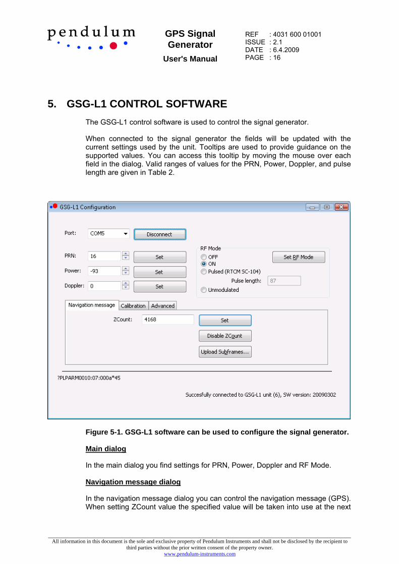
5. GSG-L1 CONTROL SOFTWARE The GSG-L1 control software is used to control the signal generator.
When connected to the signal generator the fields will be updated with the current settings used by the unit. Tooltips are used to provide guidance on the supported values. You can access this tooltip by moving the mouse over each field in the dialog. Valid ranges of values for the PRN, Power, Doppler, and pulse length are given in Table 2.
Figure 5-1. GSG-L1 software can be used to configure the signal generator.
Main dialog
In the main dialog you find settings for PRN, Power, Doppler and RF Mode.
Navigation message dialog
In the navigation message dialog you can control the navigation message (GPS). When setting ZCount value the specified value will be taken into use at the next

GPS Signal Generator
User's Manual
REF : 4031 600 01001 ISSUE : 2.1 DATE : 6.4.2009 PAGE : 17
All information in this document is the sole and exclusive property of Pendulum Instruments and shall not be disclosed by the recipient to third parties without the prior written consent of the property owner.
www.pendulum-instruments.com
time subframe ID1 is transmitted. Setting ZCount will turn on automatic updating of ZCount and parity. The “Disable ZCount” button will turn off ZCount and parity updating.
You can upload navigation messages using the “Upload Subframes…” button.
The subframes are read from a text file where the subframes should be in hexadecimal format, one message per line. An example is found in the file prn2_subframes.txt, which can be found in the installation folder. Each line should hold:
<subframeid><slot_nr><length><subframecontent>
In the middle region of the window the actual command sent to the unit is displayed on the left and on the right the user can see the acknowledgements and query results.
Calibration dialog
The calibration dialog can be used to upload new calibration data to the unit.
Advanced dialog
The button “Store Settings” will store the settings and e.g. RF mode currently used by the unit to internal memory. The stored settings will be used automatically when the unit is powered up.
The GSG-L1 software can also be used to update the embedded software of the signal generator. To upload a new software, press the “Upload Design” button and follow instructions on the screen.
5.1 Subframe maker utility
The installation software also installs a subframe maker utility in the installation directory. This command line software can be used to produce new navigation messages based on RINEX ephemeris data and YUMA almanac information. Historical RINEX information can be downloaded from e.g. the CDDIS web site (http://cddis.gsfc.nasa.gov/).
The software will produce a whole navigation message (125 subframes) for a given PRN number and output these message to screen to a specified file using the ‘-o’ option.

GPS Signal Generator
User's Manual
REF : 4031 600 01001 ISSUE : 2.1 DATE : 6.4.2009 PAGE : 18
All information in this document is the sole and exclusive property of Pendulum Instruments and shall not be disclosed by the recipient to third parties without the prior written consent of the property owner.
www.pendulum-instruments.com
Figure 2. mkSubframe command line utility can be used to produce subframes for the GSG-L1.

GPS Signal Generator
User's Manual
REF : 4031 600 01001 ISSUE : 2.1 DATE : 6.4.2009 PAGE : 19
All information in this document is the sole and exclusive property of Pendulum Instruments and shall not be disclosed by the recipient to third parties without the prior written consent of the property owner.
www.pendulum-instruments.com
6. TROUBLESHOOTING o Signal power
A common problem when setting up the signal generator is that a too strong signal is used. This may result in the receiver being jammed. When setting the signal transmitter up at a new location it is therefore recommended that the signal generator initially is configured to use the maximum internal attenuation (default value). After this the strength of the signal can be slowly increased, in steps of e.g. 5 dB, until the signal comes into the tracking loop of the receiver. Wait a moment between each attenuation change to allow the receiver to find the stronger signal.
A jammed receiver will track virtually any PRN it tries to find whereas a slightly too strong signal might cause the receiver to lock on one of the side lobes of the signal. I.e. if the receiver is not responding to changes or odd behaviours are being noticed in the receiver performance, please check the attenuation settings. A good way to test that the signal strength is suitable is to make a small change in the attenuation settings, e.g. 2-3dB, and observe the reported SNR value of the receiver. The SNR value of a correctly tuned signal should immediately respond to the new signal strength settings.
o Almanac data
If the receiver won’t find the signal this might be due to the receiver holding almanac information on GPS constellation (almanac/date/time). This will typically cause the receiver to search for only specific PRN number and the signal generated by GSG-L1 might
a) not be search for
b) be rejected,
since it is unexpected based on the used almanac information. You can ensure that this is not the case by
a) ensuring that the receiver does not receive any live signals, and
b) reset/initialize the receiver to clear out almanac and last known position. This can be achieved by doing a ‘Cold start’ of by resetting the receiver using some reset button (if available). Note that receiver On/Off will not clear the almanac information.
o Doppler
The Doppler value should be within the search space of the receiver. The recommended Doppler value at start up is 0. If the Doppler is set to very high or low values it might go out of the search space of the receiver and it will take a long time before signal is acquired.

GPS Signal Generator
User's Manual
REF : 4031 600 01001 ISSUE : 2.1 DATE : 6.4.2009 PAGE : 20
All information in this document is the sole and exclusive property of Pendulum Instruments and shall not be disclosed by the recipient to third parties without the prior written consent of the property owner.
www.pendulum-instruments.com
APPENDIX A. TECHNICAL SPECIFICATIONS
Parameter GSG-L1 RF Output GPS L1 (1575.42 MHz)
C/A Codes 1-37 (GPS)
120-158 (SBAS)
60-69 (GPS)
Data format 50 bits/s, GPS frame structure
250 bits/s, SBAS
High frequency stability
TCXO (OCXO optional)
1 Hz control resolution
Frequency adjustment range 1575.42 MHz +/- 1 kHz
Signal Power -150dBm … - 73dBm
0.05 dB control resolution
Supported pulsing schemas RTCM SC-104
High standard interfaces
• Communication
• RF connector
• Power port
RS232 (LEMO connector)
SMA(f) 50Ω,
LEMO DC connector
Antenna (optional)
• Gain
• Band width
Helix antenna with built in ground plane
+11dBic
1575 MHz ± 250 MHz
Power
• Supply voltage
• Consumption
110-240V, 50/60 Hz
1.2 W (from 6Vdc)
Environmental
• Operation Temperature
• Storage Temperature
• Sealing
-20°C to + 65°C
-55°C to + 85°C
Withstand strong jets of water. Dust tight.
User manual and documentation
Configuration and set-up software (Windows)
One-year hardware warranty
Compact design
• Size
• Weight
140 x 140 x 70 mm
1 kg