gs1100 series
TRANSCRIPT

Quick Start Guide
www.zyxel.com
GS1 1 0 0 SeriesUnm anaged Gigabit Ethernet Switch
Version 1.00Edit ion 5, 09/ 2015
Copyright © 2015 ZyXEL Com m unicat ions Corporat ion
User’s Guide

GS1100 Series User’s Guide
2
IMPORTANT!
READ CAREFULLY BEFORE USE.
KEEP THIS GUIDE FOR FUTURE REFERENCE.
Screenshots and graphics in this book may differ slight ly from your product due to differences in your product firmware or your com puter operat ing system. Every effort has been made to ensure that the inform at ion in this m anual is accurate.
• More I nformat ion
Go to support .zyxel.com to find other informat ion on the Switch.
Table of Contents
GS1100 Series User’s Guide
3
Table of Contents
Table of Contents .................................................................................................................................3
Chapter 1Getting to Know Your Switch...............................................................................................................4
1.1 Introduction .........................................................................................................................................4
1.2 Features ..............................................................................................................................................5
1.3 Applications .........................................................................................................................................6
1.3.1 Standalone Workgroup ..............................................................................................................6
1.3.2 Bridging .....................................................................................................................................6
1.4 Power Over Ethernet (PoE) ................................................................................................................7
Chapter 2Hardware Description and Connection ..............................................................................................8
2.1 Rear Panel .......................................................................................................................................8
2.1.1 Rear Panel Power Connection ..................................................................................................8
2.2 Front Panel ..........................................................................................................................................9
2.2.1 RJ-45 Auto-negotiating Ports ....................................................................................................9
2.2.2 IEEE 802.3az EEE ....................................................................................................................9
2.2.3 SFP Slots (GS1100-24 and GS1100-10HP) ..............................................................................9
2.2.4 Front Panel Connections ......................................................................................................... 11
2.2.5 Front Panel LEDs .................................................................................................................... 11
2.3 Hardware Installation ........................................................................................................................14
2.3.1 Wall Mounting ..........................................................................................................................14
2.3.2 Rack Mounting .........................................................................................................................15
2.3.3 Mounting the Switch on a Rack ...............................................................................................16
Chapter 3Troubleshooting..................................................................................................................................18
3.1 Improper Network Cabling and Topology ..........................................................................................19
Appendix A Legal Information............................................................................................................20
Index ....................................................................................................................................................29

GS1100 Series User’s Guide
4
CHAPTER 1
Getting to Know Your Switch
1.1 Introduction
This chapter describes the key features, benefits and applicat ions of your Switch.
This User ’s Guide covers the following models: GS1100-8HP, GS1100-16, GS1100-24, GS1100-24E and GS1100-10HP. The Switch is a 10/ 100/ 1000 Mbps mult i-port switch that can be used to build high-performance switched workgroup networks. The Switch is a store-and- forward device that offers low latency for high-speed networking. The Switch is fanless and designed for workgroups, departm ents or backbone com put ing environm ents for sm all businesses.
The GS1100-8HP has four GbE PoE ports that can supply power to the connected PoE powered devices.
The GS1100-10HP has eight GbE PoE ports that can supply power to the connected PoE powered devices.
The GS1100-24 and GS1100-10HP have two SFP slots for uplink connect ion. Use SFP t ransceivers in these slots for 100Mbps or 1Gbps connect ions to backbone Ethernet switches.
The Switch has a built - in algorithm that autom at ically assigns prior ity to received packets. I t can operate in low power idle m ode in com pliance with I EEE 802.3az Energy Efficient Ethernet (EEE) .
Table 1 GS1100 Series Comparison Table
PORT/SWITCH DETAILS GS1100-8HP GS1100-16 GS1100-24 GS1100-24E GS1100-10HP
10/ 100/ 1000Base-T Ethernet ports 8 16 24 24 8
100/ 1000Base-X SFP slots 2 2
802.3AT PoE ports 4 8
One physical I EEE 802.3az ON/ OFF but ton 1 1 1 1 1
One power ON/ OFF switch 1 1 1 1

Chapter 1 Getting to Know Your Switch
GS1100 Series User’s Guide
5
Figure 1 Front Panel
1.2 Features
The following are the essent ial features of the Switch.
• Conforms to I EEE 802.3, 802.3u, 802.3ab and 802.3x standards.
• Auto-negot iat ing 10/ 100/ 1000 Mbps Gigabit Ethernet (GbE) RJ-45 ports.
• Auto-sensing crossover for all 10/ 100/ 1000 Mbps Gigabit Ethernet (GbE) RJ-45 ports.
• Supports N-Way protocol for speed (10/ 100/ 1000 Mbps) and duplex mode (Half/ Full) auto-detect ion.
• Supports store-and- forward switching.
• Supports autom at ic address learning.
• Supports I EEE 802.3az EEE
• Supports I EEE 802.3af and I EEE 802.3at PoE standards (GS1100-8HP and GS1100-10HP)
• Full wire speed forwarding rate.
• Supports 802.1p CoS.
• Embedded 8K MAC address table providing 8000 MAC addresses ent r ies.
GS1100-8HP
GS1100-16
GS1100-24
GS1100-24E
GS1100-10HP

Chapter 1 Getting to Know Your Switch
GS1100 Series User’s Guide
6
1.3 Applications
This sect ion provides two network topology exam ples in which the Switch is used.
1.3.1 Standalone Workgroup
I n this applicat ion, the Switch is an ideal solut ion for small networks where rapid growth can be expected in the near future.
The Switch can be used standalone for a group of heavy t raffic users. You can connect com puters direct ly to the Switch’s port or connect other switches to the Switch.
I n this exam ple, all com puters can share high-speed applicat ions on the server. To expand the network, sim ply add m ore networking devices such as switches, routers, com puters, pr int servers etc.
Figure 2 Standalone Workgroup Exam ple
1.3.2 Bridging
With its large address table and high perform ance, the Switch is an ideal solut ion for departm ent networks to connect to the corporate backbone or for connect ing network segm ents.
The following figure depicts a typical segment br idge applicat ion of the Switch in an enterprise environment . The two networks (R&D and Sales) , the standalone server and the com puters can all com m unicate with each other and share all network resources.
Figure 3 Bridging Exam ple

Chapter 1 Getting to Know Your Switch
GS1100 Series User’s Guide
7
1.4 Power Over Ethernet (PoE)
The PoE funct ion is available for GS1100-8HP and GS1100-10HP.
Ports 1 to 4 on the GS1100-8HP are I EEE 802.3at High Power over Ethernet (PoE) compliant and can supply power of up to 30W per Ethernet port and up to the total PoE power budget per Switch.
Ports 1 to 8 on the GS1100-10HP support both the I EEE 802.3af Power over Ethernet and I EEE 802.3at High Power over Ethernet standards. The ports supply power of up to 30W per Ethernet port and up to the total PoE power budget per Switch.
The Switch is Power Sourcing Equipm ent (PSE) because it provides a source of power via its Ethernet ports. A powered device (PD) is a device such as an access point or an I P phone, that supports PoE (Power over Ethernet ) so that it can receive power from another device through a 10/100/ 1000 Mbps Ethernet port .
I n the figure below, the I P cam era and I P phone get their power direct ly from the Switch. Aside from m inim izing the need for cables and wires, PoE rem oves the hassle of t rying to find a nearby elect r ic out let to power up devices.
Figure 4 Powered Device Examples
GS1100 Series User’s Guide
8
CHAPTER 2
Hardware Description and Connection
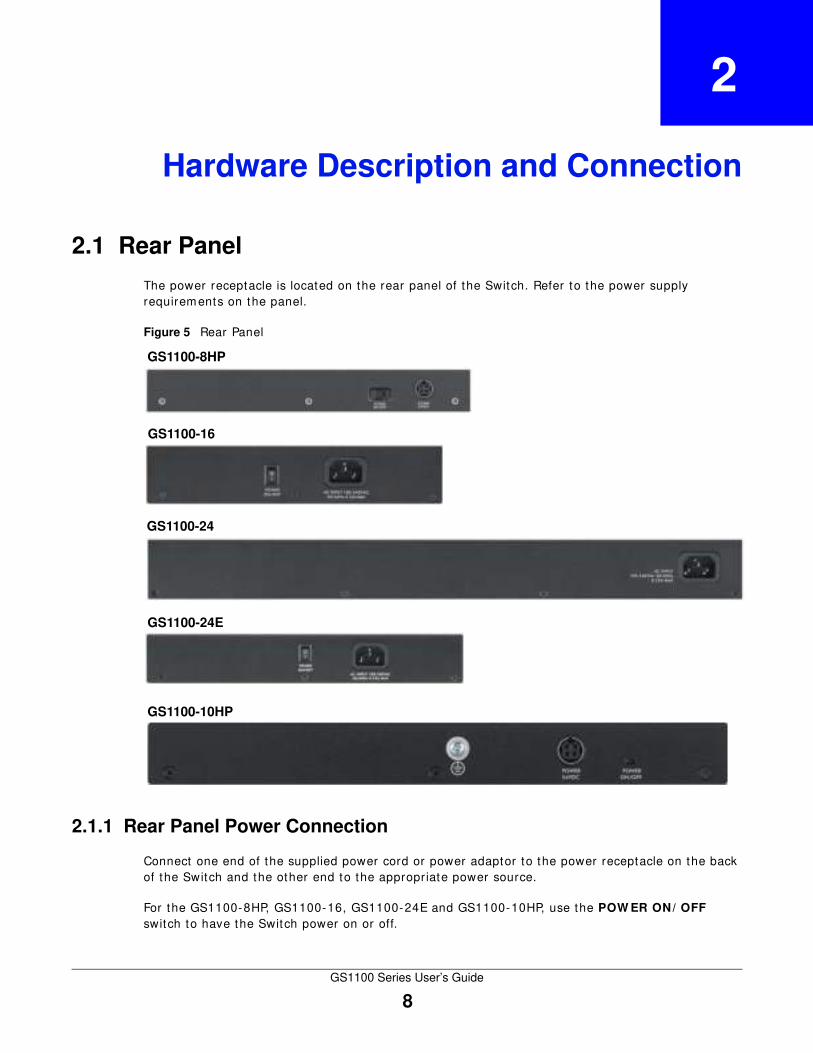
2.1 Rear Panel
The power receptacle is located on the rear panel of the Switch. Refer to the power supply requirem ents on the panel.
Figure 5 Rear Panel
2.1.1 Rear Panel Power Connection
Connect one end of the supplied power cord or power adaptor to the power receptacle on the back of the Switch and the other end to the appropriate power source.
For the GS1100-8HP, GS1100-16, GS1100-24E and GS1100-10HP, use the POW ER ON/ OFF switch to have the Switch power on or off.
GS1100-16
GS1100-24
GS1100-8HP
GS1100-24E
GS1100-10HP

Chapter 2 Hardware Description and Connection
GS1100 Series User’s Guide
9
2.2 Front Panel
The front panel of the Switch includes the auto-negot iat ing 10 Base-T/ 100 Base-TX/ 1000 Base-T RJ-45 ports and the LEDs.
The GS1100-24 and GS1100-10HP have two SFP slots. Refer to Sect ion 2.2.3 on page 9 for m ore inform at ion.
2.2.1 RJ-45 Auto-negotiating Ports
The 10 Base-T/ 100 Base-TX/ 1000 Base-T RJ-45 ports are auto-negot iat ing and auto-crossover.
An auto-negot iat ing port can detect and adjust to the opt imum Ethernet speed (10/ 100/ 1000 Mpbs) and duplex mode ( full duplex or half duplex) of the connected device.
An auto-crossover (auto-MDI / MDI -X) port autom at ically works with a st raight- through or crossover Ethernet cable.
2.2.2 IEEE 802.3az EEE
The Switch supports the I EEE 802.3az EEE (Energy Efficient Ethernet ) standard to help reduce power consumpt ion. This allows the Switch to go into power saving m ode and switch off part of receive and t ransm it circuit ry when it is not t ransm it t ing or receiving data through an Ethernet connect ion.
An EEE-enabled device init iates Low Power I dle (LPI ) signals to negot iate and wake up the remote device when there is data to be t ransm it ted. To use EEE, both devices should be EEE com pliant .
EEE is configured on a per-system basis in the Switch. I f one of the networking devices that connect to the Switch doesn't support EEE, EEE m ay not work in the Switch to save power.
Press in the I EEE 8 0 2 .3 az EEE ON/ OFF but ton on the front panel to turn on the EEE feature. Disable it if you don't want the network performance to be im pacted due to the latency from the addit ional t im e required for the sleep and wake t ransit ion or if the remote side doesn't support it .
2.2.3 SFP Slots (GS1100-24 and GS1100-10HP)
These are slots for Sm all Form - factor Pluggable (SFP) t ransceivers. A t ransceiver is a single unit that houses a t ransm it ter and a receiver. The Switch does not com e with t ransceivers. You m ust use t ransceivers that com ply with the Sm all Form - factor Pluggable (SFP) Transceiver Mult iSource Agreement (MSA) . See the SFF commit tee’s I NF-8074i specificat ion Rev 1.0 for details.
You can change t ransceivers while the Switch is operat ing. You can use different t ransceivers to connect to Ethernet switches with different types of fiber-opt ic or even copper cable connectors.
To avoid possible eye injury, do not look into an operating fiber-optic module’s connectors.
• Type: SFP connect ion interface
• Connect ion speed: 100 Megabit per second (Mbps) or 1 Gigabit per second (Gbps)
Chapter 2 Hardware Description and Connection
GS1100 Series User’s Guide
10
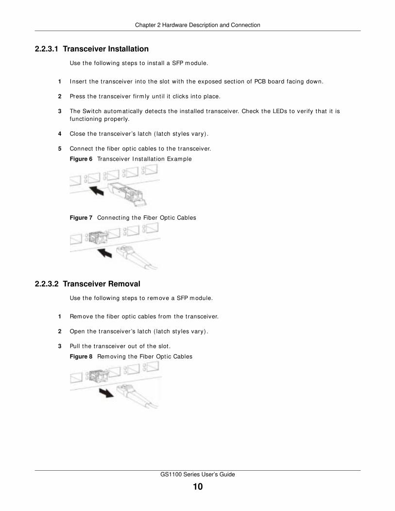
2.2.3.1 Transceiver Installation
Use the following steps to install a SFP module.
1 I nsert the t ransceiver into the slot with the exposed sect ion of PCB board facing down.
2 Press the t ransceiver firm ly unt il it clicks into place.
3 The Switch autom at ically detects the installed t ransceiver. Check the LEDs to verify that it is funct ioning properly.
4 Close the t ransceiver ’s latch ( latch styles vary) .
5 Connect the fiber opt ic cables to the t ransceiver.
Figure 6 Transceiver I nstallat ion Exam ple
Figure 7 Connect ing the Fiber Opt ic Cables
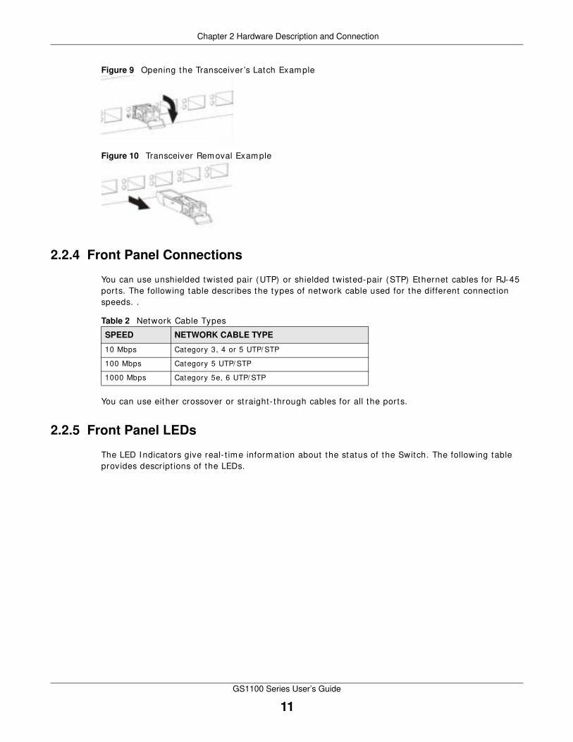
2.2.3.2 Transceiver Removal
Use the following steps to remove a SFP module.
1 Remove the fiber opt ic cables from the t ransceiver.
2 Open the t ransceiver ’s latch ( latch styles vary) .
3 Pull the t ransceiver out of the slot .
Figure 8 Rem oving the Fiber Opt ic Cables
Chapter 2 Hardware Description and Connection
GS1100 Series User’s Guide
11
Figure 9 Opening the Transceiver ’s Latch Example
Figure 10 Transceiver Rem oval Exam ple
2.2.4 Front Panel Connections
You can use unshielded twisted pair (UTP) or shielded twisted-pair (STP) Ethernet cables for RJ-45 ports. The following table describes the types of network cable used for the different connect ion speeds. .
You can use either crossover or st raight- through cables for all the ports.
2.2.5 Front Panel LEDs
The LED I ndicators give real- t im e inform at ion about the status of the Switch. The following table provides descript ions of the LEDs.
Table 2 Network Cable Types
SPEED NETWORK CABLE TYPE
10 Mbps Category 3, 4 or 5 UTP/ STP
100 Mbps Category 5 UTP/ STP
1000 Mbps Category 5e, 6 UTP/ STP

Chapter 2 Hardware Description and Connection
GS1100 Series User’s Guide
12
Figure 11 Front Panel LEDs
The following table describes the LEDs.
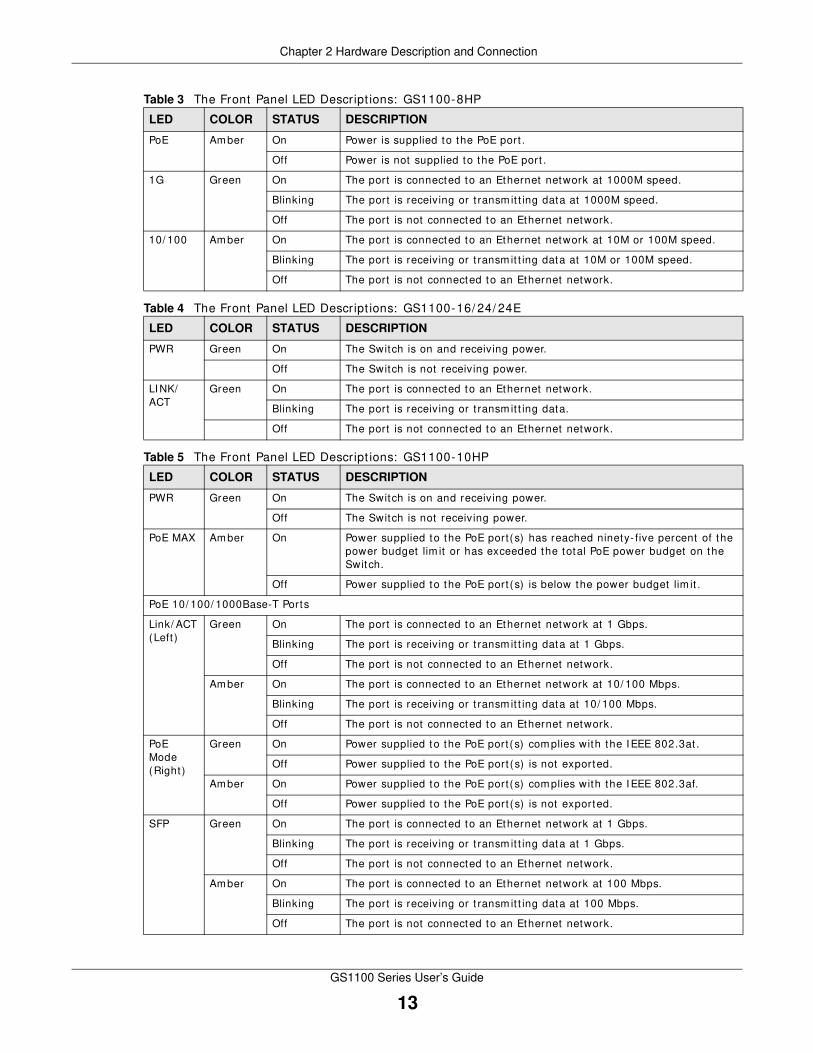
Table 3 The Front Panel LED Descript ions: GS1100-8HP
LED COLOR STATUS DESCRIPTION
PWR Green On The Switch is on and receiving power.
Off The Switch is not receiving power.
PoE MAX Red On Power supplied to the PoE port (s) reachs the power budget lim it or exceeds the total PoE power budget on the Switch.
Off Power supplied to the PoE port (s) is below the power budget lim it .
GS1100-8HP
GS1100-16
GS1100-24
GS1100-24E
GS1100-10HP
Chapter 2 Hardware Description and Connection
GS1100 Series User’s Guide
13
PoE Amber On Power is supplied to the PoE port .
Off Power is not supplied to the PoE port .
1G Green On The port is connected to an Ethernet network at 1000M speed.
Blinking The port is receiving or t ransm it t ing data at 1000M speed.
Off The port is not connected to an Ethernet network.
10/ 100 Am ber On The port is connected to an Ethernet network at 10M or 100M speed.
Blinking The port is receiving or t ransm it t ing data at 10M or 100M speed.
Off The port is not connected to an Ethernet network.
Table 4 The Front Panel LED Descript ions: GS1100-16/ 24/ 24E
LED COLOR STATUS DESCRIPTION
PWR Green On The Switch is on and receiving power.
Off The Switch is not receiving power.
LI NK/ACT
Green On The port is connected to an Ethernet network.
Blinking The port is receiving or t ransm it t ing data.
Off The port is not connected to an Ethernet network.
Table 5 The Front Panel LED Descript ions: GS1100-10HP
LED COLOR STATUS DESCRIPTION
PWR Green On The Switch is on and receiving power.
Off The Switch is not receiving power.
PoE MAX Am ber On Power supplied to the PoE port(s) has reached ninety- five percent of the power budget lim it or has exceeded the total PoE power budget on the Switch.
Off Power supplied to the PoE port (s) is below the power budget lim it .
PoE 10/ 100/ 1000Base-T Ports
Link/ ACT (Left )
Green On The port is connected to an Ethernet network at 1 Gbps.
Blinking The port is receiving or t ransm it t ing data at 1 Gbps.
Off The port is not connected to an Ethernet network.
Amber On The port is connected to an Ethernet network at 10/ 100 Mbps.
Blinking The port is receiving or t ransm it t ing data at 10/ 100 Mbps.
Off The port is not connected to an Ethernet network.
PoE Mode (Right )
Green On Power supplied to the PoE port (s) com plies with the I EEE 802.3at .
Off Power supplied to the PoE port (s) is not exported.
Amber On Power supplied to the PoE port (s) com plies with the I EEE 802.3af.
Off Power supplied to the PoE port (s) is not exported.
SFP Green On The port is connected to an Ethernet network at 1 Gbps.
Blinking The port is receiving or t ransm it t ing data at 1 Gbps.
Off The port is not connected to an Ethernet network.
Amber On The port is connected to an Ethernet network at 100 Mbps.
Blinking The port is receiving or t ransm it t ing data at 100 Mbps.
Off The port is not connected to an Ethernet network.
Table 3 The Front Panel LED Descript ions: GS1100-8HP
LED COLOR STATUS DESCRIPTION

Chapter 2 Hardware Description and Connection
GS1100 Series User’s Guide
14
2.3 Hardware Installation
See the following table for a comparison of the hardware installat ion methods of each GS1100 model:
Table 6 GS1100 Series I nstallat ion Comparison Table
Note: Ask an authorized technician to at tach the Switch to the rack/ wall.
For GS1100-8HP, GS1100-16, GS110-24E and GS1100-10HP, you can place the Switch direct ly on top of your desk or have it wall-mounted. For GS1100-16, GS1100-24 and GS110-24E, the size is suitable for rack-mount ing and you can refer to Sect ion 2.3.2 on page 15 for inst ruct ion. Take note of the following:
• The Switch should have a m inim um 25 mm space around it for vent ilat ion.
• The Switch should be placed in a desk that has a level surface and that is able to support the weight of the Switch.
To start using it , sim ply connect the power cables and turn on the Switch.
2.3.1 Wall Mounting
Do the following to at tach your Switch to a wall.
See Table 7 on page 14 for how far apart to place the screws.
1 Screw the two screws provided with your Switch into the wall (see the figure in step 2) . Use screws with 6 mm ~ 8 mm (0.24" ~ 0.31") wide heads. Do not screw the screws all the way in to the wall; leave a small gap between the head of the screw and the wall.
The gap m ust be big enough for the screw heads to slide into the screw slots and the connect ion cables to run down the back of the Switch.
Note: Make sure the screws are securely fixed to the wall and st rong enough to hold the weight of the Switch with the connect ion cables.
2 Align t he holes on t he back of t he Swit ch wit h t he screws on t he wall. Hang t he Swit ch on t he screws.
MODEL FEATURE GS1100-8HP GS1100-16 GS1100-24 GS1100-24E GS1100-10HP
Desktop Device
Wall-m ountable
Rack-m ountable
Table 7 Distance between the centers of the holes for wall mounting
MODEL DISTANCE
GS1100-8HP 120 mm
GS1100-16 148 mm
GS1100-24E 207 mm
GS1100-10HP 176mm
Chapter 2 Hardware Description and Connection
GS1100 Series User’s Guide
15
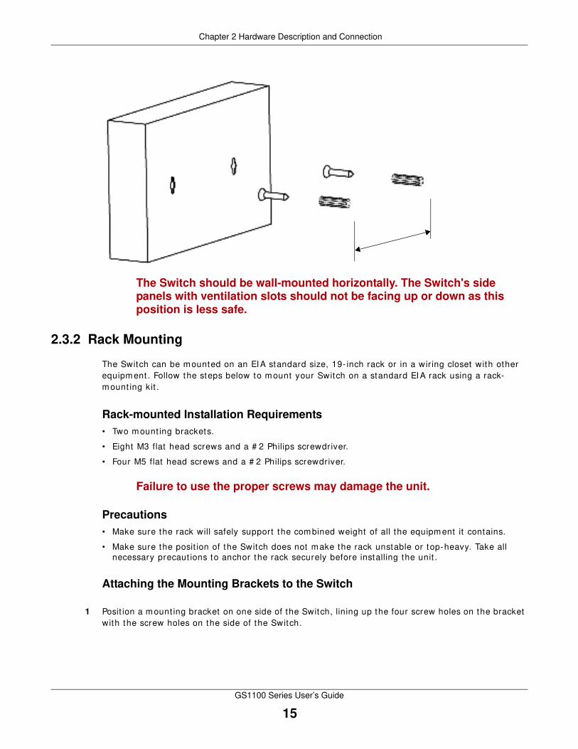
The Switch should be wall-mounted horizontally. The Switch's side panels with ventilation slots should not be facing up or down as this position is less safe.
2.3.2 Rack Mounting
The Switch can be m ounted on an EI A standard size, 19- inch rack or in a wir ing closet with other equipm ent . Follow the steps below to m ount your Switch on a standard EI A rack using a rack-m ount ing kit .
Rack-mounted Installation Requirements
• Two mount ing brackets.
• Eight M3 flat head screws and a # 2 Philips screwdriver.
• Four M5 flat head screws and a # 2 Philips screwdriver.
Failure to use the proper screws may damage the unit.
Precautions
• Make sure the rack will safely support the com bined weight of all the equipment it contains.
• Make sure the posit ion of the Switch does not m ake the rack unstable or top-heavy. Take all necessary precaut ions to anchor the rack securely before installing the unit .
Attaching the Mounting Brackets to the Switch
1 Posit ion a m ount ing bracket on one side of the Switch, lining up the four screw holes on the bracket with the screw holes on the side of the Switch.

Chapter 2 Hardware Description and Connection
GS1100 Series User’s Guide
16
Figure 12 At taching the Mount ing Brackets (GS1100-16 and GS1100-24E)
Figure 13 At taching the Mount ing Brackets (GS1100-24)
2 Using a # 2 Philips screwdriver, install the M3 flat head screws through the mount ing bracket holes into the Switch.
3 Repeat steps 1 and 2 to install the second m ount ing bracket on the other side of the Switch.
4 You m ay now m ount the Switch on a rack. Proceed to the next sect ion.
2.3.3 Mounting the Switch on a Rack
1 Posit ion a m ount ing bracket ( that is already at tached to the Switch) on one side of the rack, lining up the two screw holes on the bracket with the screw holes on the side of the rack.

Chapter 2 Hardware Description and Connection
GS1100 Series User’s Guide
17
Figure 14 Mount ing the Switch on a Rack (GS1100-16 and GS1100-24E)
Figure 15 Mount ing the Switch on a Rack (GS1100-24)
2 Using a # 2 Philips screwdriver, install the M5 flat head screws through the mount ing bracket holes into the rack.
3 Repeat steps 1 and 2 to at tach the second mount ing bracket on the other side of the rack.

GS1100 Series User’s Guide
18
CHAPTER 3
Troubleshooting
This sect ion describes com m on problem s you m ay encounter with the Switch and possible solut ions.
Troubleshoot the Switch using the LEDs to detect problems.
The PW R LED on the front panel does not light up.
• Check the connect ions from your Switch to the power source. Make sure you are using the supplied power cord and that you are using an appropriate power source. Refer to the product specificat ions.
• Make sure the power source is turned on and that the Switch is receiving sufficient power.
• I f these steps fail to correct the problem , contact your local dist r ibutor for assistance.
The LNK/ ACT, 1 G or 1 0 / 1 0 0 LED does not light up when a device is connected.
• Verify that the at tached device(s) is turned on and properly connected to your Switch.
• Make sure the network adapters are working on the at tached devices.
• Verify that proper network cable type is used and its length does not exceed 100 meters. For m ore inform at ion on network cable types, see Sect ion 3.1 on page 19.
The PoE LED is off and/ or power is not being supplied to my PoE-enabled device. (For GS1100-8HP and GS1100-10HP)
• Check to see that the power adaptor is securely connected to the GS1100-8HP (or GS1100-10HP) and an appropriate power source. Make sure the power source is on and funct ioning properly.
• Check that the Ethernet cables are connected properly and that you are using the correct type of Ethernet cable. Contact your local dist r ibutor if the problem persists.

Chapter 3 Troubleshooting
GS1100 Series User’s Guide
19
3.1 Improper Network Cabling and Topology
I mproper network cabling or topology setup is a comm on cause of poor network perform ance or even network failure.
Figure 16 Troubleshoot ing I mproper Network Cabling and Topology
PROBLEM CORRECTIVE ACTION
Faulty cables Using faulty network cables m ay affect data rates and have an im pact on your network perform ance. Replace with new standard network cables.
Non-standard network cables
Non-standard cables m ay increase the num ber of network collisions and cause other network problem s that affect your network perform ance. Refer to Sect ion 2.2.4 on page 11 for m ore inform at ion on network cable types.
Cabling Length I f you use longer cables than are needed, t ransm ission quality may be affected.
The network cables should not be longer than the lim it of 100 m eters.
Too m any hubs between the computers in the network
Too m any hubs (or repeaters) between the connected computers in the network may increase the number of network collision or other network problem s. Rem ove unnecessary hubs from the network.
A loop in the data path
A data path loop forms when there is m ore than one path or route between two networked computers. This results in broadcast storm s that will severely affect your network perform ance. Make sure there are no loops in your network topology.

GS1100 Series User’s Guide
20
APPENDIX A
Legal Information
CopyrightCopyright © 2015 by ZyXEL Com m unicat ions Corporat ion.
The contents of this publicat ion m ay not be reproduced in any part or as a whole, t ranscribed, stored in a ret r ieval system , t ranslated into any language, or t ransm it ted in any form or by any m eans, elect ronic, m echanical, m agnet ic, opt ical, chem ical, photocopying, m anual, or otherwise, without the pr ior writ ten perm ission of ZyXEL Com m unicat ions Corporat ion.
Published by ZyXEL Communicat ions Corporat ion. All r ights reserved.
DisclaimerZyXEL does not assum e any liability ar ising out of the applicat ion or use of any products, or software described herein. Neither does it convey any license under it s patent r ights nor the patent r ights of others. ZyXEL further reserves the r ight to m ake changes in any products described herein without not ice. This publicat ion is subject to change without not ice.
Regulatory Notice and Statement (Class A)
Model List : GS1100-8HP, GS1100-24
United States of America
Federal Com m unicat ions Com m ission (FCC) EMC Statem ent
• This device complies with Part 15 of FCC rules. Operat ion is subject to the following two condit ions:(1) This device m ay not cause harm ful interference.(2) This device must accept any interference received, including inter ference that m ay cause undesired operat ions.
• Changes or m odificat ions not expressly approved by the party responsible for com pliance could void the user ’s authority to operate the equipment .
• This equipment has been tested and found to com ply with the lim its for a Class A digital device, pursuant to part 15 of the FCC Rules. These lim its are designed to provide reasonable protect ion against harm ful interference when the equipm ent is operated in a commercial environm ent . This equipment generates, uses, and can radiate radio frequency energy and, if not installed and used in accordance with the inst ruct ion m anual, may cause harm ful interference to radio com m unicat ions. Operat ion of this equipm ent in a resident ial area is likely to cause harm ful interference in which case the user will be required to correct the interference at his own expense.
CanadaThe following inform at ion applies if you use the product within Canada area
I ndust ry Canada I CES statement
CAN I CES-3 (A) / NMB-3(A)
European Union
The following inform at ion applies if you use the product within the European Union.
CE EMC statem ent

Appendix A Legal Information
GS1100 Series User’s Guide
21
This is Class A Product . I n dom est ic environm ent this product m ay cause radio interference in which case the user m ay be required to take adequate m easures.
List of Nat ional Codes
Not ices
CLASS 1 LASER PRODUCT
APPAREIL À LASER DE CLASS 1
PRODUCT COMPLI ES WI TH 21 CFR 1040.10 AND 1040.11.
PRODUIT CONFORME SELON 21 CFR 1040.10 ET 1040.11.
Safety Warnings• Do NOT use this product near water, for exam ple, in a wet basem ent or near a swim m ing pool.• Do NOT expose your device to dampness, dust or corrosive liquids.• Do NOT store things on the device.• Do NOT install, use, or service this device during a thunderstorm . There is a rem ote r isk of elect r ic shock from lightning.• Connect ONLY suitable accessories to the device.• Do NOT open the device or unit . Opening or rem oving covers can expose you to dangerous high voltage points or other r isks. ONLY
qualified service personnel should service or disassem ble this device. Please contact your vendor for further inform at ion. • Make sure to connect the cables to the correct ports.• Place connect ing cables carefully so that no one will step on them or stum ble over them.• Always disconnect all cables from this device before servicing or disassembling.• Use ONLY an appropriate power adaptor or cord for your device. Connect it to the r ight supply voltage ( for exam ple, 110V AC in North
Am erica or 230V AC in Europe) .• Do NOT rem ove the plug and connect it to a power out let by itself; always at tach the plug to the power adaptor first before connect ing
it to a power out let .• Do NOT allow anything to rest on the power adaptor or cord and do NOT place the product where anyone can walk on the power
adaptor or cord.• Do NOT use the device if the power adaptor or cord is damaged as it m ight cause elect rocut ion.• I f the power adaptor or cord is dam aged, rem ove it from the device and the power source.• Do NOT at tem pt to repair the power adaptor or cord. Contact your local vendor to order a new one.• Do not use the device outside, and m ake sure all the connect ions are indoors. There is a rem ote r isk of elect r ic shock from lightning. • CAUTI ON: RI SK OF EXPLOSI ON I F BATTERY (on the m otherboard) I S REPLACED BY AN I NCORRECT TYPE. DISPOSE OF USED
BATTERI ES ACCORDING TO THE INSTRUCTI ONS. Dispose them at the applicable collect ion point for the recycling of elect r ical and elect ronic equipm ent . For detailed inform at ion about recycling of this product , please contact your local city off ice, your household waste disposal service or the store where you purchased the product .
• Do NOT obst ruct the device vent ilat ion slots, as insufficient air flow may harm your device. • Antenna Warning! This device m eets ETSI and FCC cert if icat ion requirem ents when using the included antenna(s) . Only use the
included antenna(s) . • I f you wall mount your wall-mountable device, make sure that no elect r ical lines, gas or water pipes will be damaged.
The following warnings apply if product is disconnect device:
• A readily accessible disconnect device shall be incorporated external to the equipm ent ; and/ or
The socket-out let shall be installed near the equipm ent and shall be easily accessible.
WEEE Direct ive
COUNTRY ISO 3166 2 LETTER CODE COUNTRY ISO 3166 2 LETTER CODE
Austr ia AT Malta MT
Belgium BE Netherlands NL
Cyprus CY Poland PL
Czech Republic CR Portugal PT
Denm ark DK Slovakia SK
Estonia EE Slovenia SI
Finland FI Spain ES
France FR Sweden SE
Germany DE United Kingdom GB
Greece GR Iceland I S
Hungary HU Liechtenstein LI
I reland IE Norway NO
I taly IT Switzerland CH
Latvia LV Bulgaria BG
Lithuania LT Rom ania RO
Luxem bourg LU Turkey TR
Appendix A Legal Information
GS1100 Series User’s Guide
22
Your product is marked with this symbol, which is known as the WEEE m ark. WEEE stands for Waste Elect ronics and Elect r ical Equipment . I t m eans that used elect r ical and elect ronic products should not be m ixed with general waste. Used elect r ical and elect ronic equipm ent should be t reated separately.
Die folgende Sym bol bedeutet , dass I hr Produkt und/ oder seine Bat ter ie gem äß den ört lichen Best im m ungen get rennt vom Hausm üll entsorgt werden muss. Wenden Sie sich an eine Recyclingstat ion, wenn dieses Produkt das Ende seiner Lebensdauer erreicht hat . Zum Zeitpunkt der Entsorgung wird die get rennte Sammlung von Produkt und/ oder seiner Bat terie dazu beit ragen, natürliche Ressourcen zu sparen und die Umwelt und die menschliche Gesundheit zu schützen.
El símbolo de abajo indica que según las regulaciones locales, su producto y/ o su batería deberán depositarse como basura separada de la domést ica. Cuando este producto alcance el final de su vida út il, llévelo a un punto limpio. Cuando llegue el momento de desechar el producto, la recogida por separado éste y/ o su batería ayudará a salvar los recursos naturales y a proteger la salud hum ana y m edioam biental.
Le symbole ci-dessous signifie que selon les réglementat ions en vigueur vot re produit et / ou sa bat terie doivent êt re élim inés séparém ent des ordures m énagères. Lorsque ce produit at teint sa fin de vie, amenez- le à un cent re de recyclage pour qu’il soit m is au rebut . La collecte séparée de vot re produit et / ou de sa bat ter ie permet t ra une meilleure protect ion de l'environnem ent et de la santé humaine.
Questo sim bolo significa che secondo i regolam ent i locali il prodot to e/ o la sua bat ter ia devono essere t rat tat i separatamente dai r if iut i domest ici. Quando questo prodot to raggiunge la fine della vita di servizio portatelo ad una stazione di r iciclaggio. Questo t rat tam ento separato del prodot to e/ o della sua bat ter ia aiuta a r isparm iare r isorse naturali e a proteggere l'am biente.
Sym bolen innebär at t enligt lokal lagst iftning ska produkten och/ eller dess bat ter i kastas separat från hushållsavfallet . När den här produkten når slutet av sin livslängd ska du ta den t ill en återvinningsstat ion. Separat insam ling av din produkt och / eller dess bat ter i hjälper t ill at t både spara naturresurser och se t ill at t m iljön når en hållbar utveckling.

Appendix A Legal Information
GS1100 Series User’s Guide
23
Environmental Product Declaration

Appendix A Legal Information
GS1100 Series User’s Guide
24
台灣以下訊息僅適用於產品銷售至台灣地區這是甲類的資訊產品,在居住的環境中使用時,可能會造成射頻干擾,在這種情況下,使用者會被要求採取某些適當的對策。
安全警告為了您的安全,請先閱讀以下警告及指示 :• 請勿將此產品接近水、火焰或放置在高溫的環境。• 避免設備接觸• 任何液體 - 切勿讓設備接觸水、雨水、高濕度、污水腐蝕性的液體或其他水份。• 灰塵及污物 - 切勿接觸灰塵、污物、沙土、食物或其他不合適的材料。• 切勿重摔或撞擊設備,並勿使用不正確的電源變壓器。若接上不正確的電源變壓器會有爆炸的風險。• 請勿隨意更換產品內的電池。• 如果更換不正確之電池型式,會有爆炸的風險,請依製造商說明書處理使用過之電池。• 請將廢電池丟棄在適當的電器或電子設備回收處。• 請勿將設備解體。• 請勿阻礙設備的散熱孔,空氣對流不足將會造成設備損害。• 請插在正確的電壓供給插座 ( 如 : 北美 / 台灣電壓 110V AC,歐洲是 230V AC)。• 假若電源變壓器或電源變壓器的纜線損壞,請從插座拔除,若您還繼續插電使用,會有觸電死亡的風險。• 請勿試圖修理電源變壓器或電源變壓器的纜線,若有毀損,請直接聯絡您購買的店家,購買一個新的電源變壓器。• 請勿將此設備安裝於室外,此設備僅適合放置於室內。• 請勿隨一般垃圾丟棄。• 請參閱產品背貼上的設備額定功率。• 請參考產品型錄或是彩盒上的作業溫度。
Regulatory Notice and Statement (Class B)
Model List : GS1100-10HP, GS1100-16, GS1100-24E
United States of America
Federal Com m unicat ions Com m ission (FCC) EMC Statem ent
• This device complies with Part 15 of FCC rules. Operat ion is subject to the following two condit ions:(1) This device m ay not cause harm ful interference.(2) This device must accept any interference received, including inter ference that m ay cause undesired operat ions.
• Changes or m odificat ions not expressly approved by the party responsible for com pliance could void the user ’s authority to operate the equipment .
• This product has been tested and com plies with the specif icat ions for a Class B digital device, pursuant to Part 15 of the FCC Rules. These lim its are designed to provide reasonable protect ion against harm ful interference in a resident ial installat ion. This equipm ent generates, uses, and can radiate radio frequency energy and, if not installed and used according to the inst ruct ions, m ay cause harm ful interference to radio com m unicat ions. However, there is no guarantee that interference will not occur in a part icular installat ion.
• I f this equipment does cause harm ful interference to radio or television recept ion, which is found by turning the equipm ent off and on, the user is encouraged to t ry to correct the inter ference by one or m ore of the following measures:• Reorient or relocate the receiving antenna • I ncrease the separat ion between the equipm ent or devices • Connect the equipm ent to an out let other than the receiver ’s • Consult a dealer or an experienced radio/ TV technician for assistance
CanadaThe following inform at ion applies if you use the product within Canada area
I ndust ry Canada I CES statement
CAN I CES-3 (B) / NMB-3(B)
List of Nat ional Codes
COUNTRY ISO 3166 2 LETTER CODE COUNTRY ISO 3166 2 LETTER CODE
Austr ia AT Malta MT
Belgium BE Netherlands NL
Cyprus CY Poland PL
Czech Republic CR Portugal PT
Denm ark DK Slovakia SK
Appendix A Legal Information
GS1100 Series User’s Guide
25
Safety Warnings• Do NOT use this product near water, for exam ple, in a wet basem ent or near a swim m ing pool.• Do NOT expose your device to dampness, dust or corrosive liquids.• Do NOT store things on the device.• Do NOT install, use, or service this device during a thunderstorm . There is a rem ote r isk of elect r ic shock from lightning.• Connect ONLY suitable accessories to the device.• Do NOT open the device or unit . Opening or rem oving covers can expose you to dangerous high voltage points or other r isks. ONLY
qualified service personnel should service or disassem ble this device. Please contact your vendor for further inform at ion. • Make sure to connect the cables to the correct ports.• Place connect ing cables carefully so that no one will step on them or stum ble over them.• Always disconnect all cables from this device before servicing or disassembling.• Use ONLY an appropriate power adaptor or cord for your device. Connect it to the r ight supply voltage ( for exam ple, 110V AC in North
Am erica or 230V AC in Europe) .• Do NOT rem ove the plug and connect it to a power out let by itself; always at tach the plug to the power adaptor first before connect ing
it to a power out let .• Do NOT allow anything to rest on the power adaptor or cord and do NOT place the product where anyone can walk on the power
adaptor or cord.• Do NOT use the device if the power adaptor or cord is damaged as it m ight cause elect rocut ion.• I f the power adaptor or cord is dam aged, rem ove it from the device and the power source.• Do NOT at tem pt to repair the power adaptor or cord. Contact your local vendor to order a new one.• Do not use the device outside, and m ake sure all the connect ions are indoors. There is a rem ote r isk of elect r ic shock from lightning. • CAUTI ON: RI SK OF EXPLOSI ON I F BATTERY (on the m otherboard) I S REPLACED BY AN I NCORRECT TYPE. DISPOSE OF USED
BATTERI ES ACCORDING TO THE INSTRUCTI ONS. Dispose them at the applicable collect ion point for the recycling of elect r ical and elect ronic equipm ent . For detailed inform at ion about recycling of this product , please contact your local city off ice, your household waste disposal service or the store where you purchased the product .
• Do NOT obst ruct the device vent ilat ion slots, as insufficient air flow may harm your device. • Antenna Warning! This device m eets ETSI and FCC cert if icat ion requirem ents when using the included antenna(s) . Only use the
included antenna(s) . • I f you wall mount your wall-mountable device, make sure that no elect r ical lines, gas or water pipes will be damaged.
The following warnings apply if product is disconnect device:
• A readily accessible disconnect device shall be incorporated external to the equipm ent ; and/ or• The socket-out let shall be installed near the equipm ent and shall be easily accessible.
Environment Statement
ErP (Energy- related Products)
All ZyXEL products put on the EU m arket in com pliance with the requirem ent of the European Parliam ent and the Council published Direct ive 2009/ 125/ EC establishing a fram ework for the set t ing of ecodesign requirem ents for energy- related products ( recast ) , so called as “ErP Direct ive (Energy- related Products direct ive) as well as ecodesign requirem ent laid down in applicable im plem ent ing m easures, power consum pt ion has sat isfied regulat ion requirem ents which are:
• Network standby power consum pt ion < 12W and/ or• Off mode power consum pt ion < 0.5W and/ or• Standby mode power consum pt ion < 0.5W.
Please refer to "Wireless" chapter for m ore details on Wireless set t ings.
WEEE Direct ive
Your product is marked with this symbol, which is known as the WEEE m ark. WEEE stands for Waste Elect ronics and Elect r ical Equipment . I t m eans that used elect r ical and elect ronic products should not be m ixed with general waste. Used elect r ical and elect ronic equipm ent should be t reated separately.
Die folgende Sym bol bedeutet , dass I hr Produkt und/ oder seine Bat ter ie gem äß den ört lichen Best im m ungen get rennt vom Hausm üll entsorgt werden muss. Wenden Sie sich an eine Recyclingstat ion, wenn dieses Produkt das Ende seiner Lebensdauer erreicht hat . Zum Zeitpunkt der Entsorgung wird die get rennte Sammlung von Produkt und/ oder seiner Bat terie dazu beit ragen, natürliche Ressourcen zu sparen und die Umwelt und die menschliche Gesundheit zu schützen.
Estonia EE Slovenia SI
Finland FI Spain ES
France FR Sweden SE
Germany DE United Kingdom GB
Greece GR Iceland I S
Hungary HU Liechtenstein LI
I reland IE Norway NO
I taly IT Switzerland CH
Latvia LV Bulgaria BG
Lithuania LT Rom ania RO
Luxem bourg LU Turkey TR
COUNTRY ISO 3166 2 LETTER CODE COUNTRY ISO 3166 2 LETTER CODE

Appendix A Legal Information
GS1100 Series User’s Guide
26
El símbolo de abajo indica que según las regulaciones locales, su producto y/ o su batería deberán depositarse como basura separada de la domést ica. Cuando este producto alcance el final de su vida út il, llévelo a un punto limpio. Cuando llegue el momento de desechar el producto, la recogida por separado éste y/ o su batería ayudará a salvar los recursos naturales y a proteger la salud hum ana y m edioam biental.
Le symbole ci-dessous signifie que selon les réglementat ions en vigueur vot re produit et / ou sa bat terie doivent êt re élim inés séparém ent des ordures m énagères. Lorsque ce produit at teint sa fin de vie, amenez- le à un cent re de recyclage pour qu’il soit m is au rebut . La collecte séparée de vot re produit et / ou de sa bat ter ie permet t ra une meilleure protect ion de l'environnem ent et de la santé humaine.
Questo sim bolo significa che secondo i regolam ent i locali il prodot to e/ o la sua bat ter ia devono essere t rat tat i separatamente dai r if iut i domest ici. Quando questo prodot to raggiunge la fine della vita di servizio portatelo ad una stazione di r iciclaggio. Questo t rat tam ento separato del prodot to e/ o della sua bat ter ia aiuta a r isparm iare r isorse naturali e a proteggere l'am biente.
Sym bolen innebär at t enligt lokal lagst iftning ska produkten och/ eller dess bat ter i kastas separat från hushållsavfallet . När den här produkten når slutet av sin livslängd ska du ta den t ill en återvinningsstat ion. Separat insam ling av din produkt och / eller dess bat ter i hjälper t ill at t både spara naturresurser och se t ill at t m iljön når en hållbar utveckling.
Appendix A Legal Information
GS1100 Series User’s Guide
27
Environmental Product Declaration
Appendix A Legal Information
GS1100 Series User’s Guide
28
Viewing CertificationsGo to ht tp: / / www.zyxel.com to view this product ’s docum entat ion and cert ificat ions.
ZyXEL Limited WarrantyZyXEL warrants to the original end user (purchaser) that this product is free from any defects in m aterial or workm anship for a specific period ( the Warranty Period) from the date of purchase. The Warranty Period varies by region. Check with your vendor and/ or the author ized ZyXEL local dist r ibutor for details about the Warranty Period of this product . During the warranty per iod, and upon proof of purchase, should the product have indicat ions of failure due to faulty workm anship and/ or m aterials, ZyXEL will, at it s discret ion, repair or replace the defect ive products or com ponents without charge for either parts or labor, and to whatever extent it shall deem necessary to restore the product or com ponents to proper operat ing condit ion. Any replacement will consist of a new or re-manufactured funct ionally equivalent product of equal or higher value, and will be solely at the discret ion of ZyXEL. This warranty shall not apply if the product has been m odified, m isused, tampered with, damaged by an act of God, or subjected to abnorm al working condit ions.
Note
Repair or replacem ent , as provided under this warranty, is the exclusive rem edy of the purchaser. This warranty is in lieu of all other warrant ies, express or im plied, including any im plied warranty of merchantability or fitness for a part icular use or purpose. ZyXEL shall in no event be held liable for indirect or consequent ial damages of any kind to the purchaser.
To obtain the services of this warranty, contact your vendor. You m ay also refer to the warranty policy for the region in which you bought the device at ht tp: / / www.zyxel.com / web/ support_warranty_info.php.
Regist rat ion
Register your product online to receive e-mail not ices of firmware upgrades and inform at ion at www.zyxel.com for global products, or at www.us.zyxel.com for North Am erican products.
Open Source LicensesThis product contains in part som e free software dist r ibuted under GPL license terms and/ or GPL like licenses. Open source licenses are provided with the f irm ware package. You can download the latest firm ware at www.zyxel.com . I f you cannot find it there, contact your vendor or ZyXEL Technical Support at [email protected] .tw.
To obtain the source code covered under those Licenses, please contact your vendor or ZyXEL Technical Support at [email protected].

Index
GS1100 Series User’s Guide
29
Index
Numbers
10/ 100/ 1000 Mbps 4
A
Applicat ions 6
Segment Bridge 6
auto-negot iat ing ports 9
C
Cabling Length 19
cert ificat ionsnot ices 21
viewing 28
copyright 20
D
Data path loop 19
disclaimer 20
E
EEE 4, 9
Energy Efficient Ethernet 9
F
Faulty cables 19
FCC interference statem ent 20, 24
Front Panel 9
Front Panel Connect ions 11
H
High Power over Ethernet 7
I
I EEE 802.3at 7
I EEE 802.3az 9
installat ion
precaut ions 15
t ransceivers 10
L
LED Descript ions
LK/ ACT 13
PWR 12, 13
Low Power I dle 9
LPI signal 9
M
m ount ing brackets 15
N
network cable
crossover 11
st raight- through 11
Network Cable Types 11
Non-standard network cables 19

Index
GS1100 Series User’s Guide
30
P
PD 7
PoE 7
power supplying 7
Power over Ethernet 7
power saving 9
powered device 7
product regist rat ion 28
R
rack mount ing 15
Rear Panel 8
Rear Panel Power Connect ion 8
regist rat ion
product 28
S
Sm all Form - factor Pluggable (SFP) 9
Standalone Workgroup 6
T
t ransceiver Mult iSource Agreement (MSA) 9
t ransceivers 9
installat ion 10
rem oval 10
Troubleshoot ing
I mproper Network Cabling and Topology 19
W
wall mount ing 14
warranty 28
note 28