growtech 3 ha
DESCRIPTION
Growtech 3 haTRANSCRIPT
Armenian Harvest Promotion Center 10 Vazgen Sargsyan Street, office 95 Attn. Mr. Harutyunyan Armenia Project Ref: 212ARM431 - V Offer Ref: 100 Gemeente Westland (Naaldwijk), The Netherlands, 14.03.2012 Dear Sirs, We hereby have the pleasure in submitting you a technical description for the supply of a greenhouse ‘Venlo type 8,00 m’ (sections 4.50 m and columnheight 5.50 m). Total area for cultivation of vegetables is ~30.218 m² and a service-building of ~1.679 m². - assumed project altitude : 1.050 - 2.340 m. In these greenhouses we offer you the delivery of:
- a service area (with a heating room and irrigation room); - a greenhouse computer control system - a complete heating system with CO2-dosing, running on natural gas
(in emergency situations light oil will be used as fuel); - a complete irrigation system (hydroponics); - a complete screening system (energy saving and shadow); - a lighting system for young plant area; - a steel hanging gutter system; - internal transport - tomato grader installation - cold store - tomato seeds - fertilizers - pesticides - emergency power unit - ‘Georgia’ spray cart - high wire hooks - assembly and construction works - finally we offer you supervision during construction.
The supply of the inside Zeus dollies for the foundation is included in this offer. For the perimeter foundation we do include foundation drawings and the services of a supervisor.

We do supply the materials Free Carrier Gemeente Westland, The Netherlands, according Incoterms 2010-edition.The materials will be loaded in trucks or containers. Packing as commonly known in shipping glasshouse materials and according to the general conditions known for sea or truck freight. The production and construction of our greenhouses takes place according to BRL 8000 for which a Horti-Q certificate was received. We work according to the quality standards of the Horti-Q Quality system given by the foundation of recognition of Dutch greenhousebuilders. HORTI Q Why certification? Greenhouse horticulture worldwide and in The Netherlands is making enormous leaps in development, both in terms of scale and in terms of the complexity of the equipment. Developments in the areas of energy, heat storage, robotics and climate technology – to name but a handful of current issues – have created the need for a more transparent quality system. The grower therefore wants to be certain that his greenhouse and equipment have been designed and built to objective standards. The HortiQ certificate offers this assurance! This is also the reason why the HortiQ quality system is supported by important players in the market such as:
• The Netherlands Ministry of Agriculture, Nature Management and Food Quality
• AVAG – Forum for Suppliers to Greenhouse Horticulture
• Interpolis (insurance company)
• OVTO – Organisation of Horticultural Consultants and Researchers
• ABN AMRO
Alongside the knowledge institutions like TNO and the industry itself, these players have made an active contribution to the development of the HortiQ quality system. How does HortiQ certification work? HortiQ uses two assessment guidelines (BRL):
• BRL8000 “product / process certificate”: assessment of the general quality policy (“process”)
and the greenhouses and / or equipment supplied (“product”) on the basis of one of the
three quality guidelines
• BRL8001 “quality system certificate”: assessment of the general quality policy (for
companies whose products are not covered by one of the three quality guidelines).
A company which applies for certification must ensure that its products and operating processes comply with the requirements contained in the quality guidelines and the BRL. When the company has examined all its procedures and processes, the first audit can be carried out by a recognised certifying body (Kiwa N.V. at the start of the quality system). The names of certified companies are published at the website www.hortiq.nl The HortiQ certificate is valid for a period of the three years. During this period the certificate holder will undergo an annual interim check by the certifying body. After your positive reaction on our offer we can discuss in detail all the technical aspects, time scheduling and payment conditions of this project with you.

Should any question arise from our quotation, please do not hesitate to contact us immediately. This not being the situation we trust that the quotation is as requested and we look forward to your reply at your earliest convenience. Yours faithfully, Growtech Holland den Heijer B.V. Ron P. den Heijer Director
1 Table of contents
1 Table of contents ................................................................................................................................ 4
2 Type of greenhouse ............................................................................................................................ 6
3 Dimensions ......................................................................................................................................... 6
4 Foundation .......................................................................................................................................... 7
5 Steel construction ............................................................................................................................... 8
6 Aluminium (Alcoa greenhouse systems) ........................................................................................... 9
7 Doors ................................................................................................................................................. 10
8 Gutters ............................................................................................................................................... 10
9 Drainage ............................................................................................................................................ 10
10 Condensation water drainage ....................................................................................................... 10
11 Ventilation mechanism ................................................................................................................. 11
12 Glass and glazing (for your information only) ............................................................................. 11
13 General .......................................................................................................................................... 12
14 Standards ...................................................................................................................................... 12
15 Screening installation ................................................................................................................... 14
16 Gable screening ............................................................................................................................ 15
17 Boiler ............................................................................................................................................. 16
18 Burner installation......................................................................................................................... 17
19 Flue gas condenser ....................................................................................................................... 18
20 Header installation ........................................................................................................................ 20
21 Transport line ................................................................................................................................ 21
22 Heating system general ................................................................................................................ 22
23 Pipe-rail heating ............................................................................................................................ 23
24 Grow pipe heating ......................................................................................................................... 25
25 Snow pipe heating......................................................................................................................... 26
26 Service building heating ............................................................................................................... 26
27 Irrigation water preheater ............................................................................................................. 27
28 Water treatment / partial flow filter ............................................................................................... 27
29 Heat storage installation ............................................................................................................... 28
30 Insulation ....................................................................................................................................... 29
31 Paintwork ....................................................................................................................................... 29
32 Boiler room heating ...................................................................................................................... 29
33 Electrical installation .................................................................................................................... 30
34 Recirculation fans ......................................................................................................................... 34
35 Priva Integro computer system .................................................................................................... 35
36 Lighting system for young plant area .......................................................................................... 38
37 Drip irrigation system ................................................................................................................... 40
38 Overhead irrigation system - propagation area ........................................................................... 42
39 Drainwater collection and re-using .............................................................................................. 43
40 HP-UV Disinfection system ........................................................................................................... 45
41 Transmission meter ...................................................................................................................... 47
42 Water storage tank ........................................................................................................................ 47
43 Rainwater collection system......................................................................................................... 48
44 Condens water collection system ................................................................................................ 49
45 CO2 dosing system, using fluegas of boiler................................................................................. 49

46 Fog system ................................................................................................................................... 50
47 Crop gutter system for cultivating vegetables............................................................................. 53
48 Substrate with accessories .......................................................................................................... 60
49 Tools .............................................................................................................................................. 60
50 Ground cover plastic .................................................................................................................... 60
51 Grading line for medium size round tomatoes ............................................................................ 61
52 Cold store ...................................................................................................................................... 63
53 Emergency power unit – generator set ........................................................................................ 68
54 Internal transport .......................................................................................................................... 69
55 High wire hooks ............................................................................................................................ 69
56 Spray cart “Georgia” ..................................................................................................................... 70
57 Construction supervision ............................................................................................................. 71
58 Assembly and construction works ............................................................................................... 71
59 Freight ........................................................................................................................................... 72
60 Materials loading and packing ...................................................................................................... 72
61 Obligations of the Client ............................................................................................................... 73
62 Delivery .......................................................................................................................................... 74
63 General conditions ........................................................................................................................ 74
64 Additional terms ............................................................................................................................ 75
65 Price breakdown 3 hectares greenhouse for tomatoes ............................................................... 76
6/77
GREENHOUSE The production and construction of our greenhouses takes place according to BRL 8000 for which a Horti-Q certificate was received. We work according to the quality standards of the Horti-Q Quality system given by the foundation of recognition of Dutch greenhousebuilders.
2 Type of greenhouse
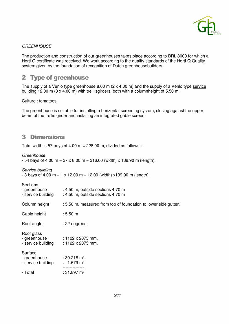
The supply of a Venlo type greenhouse 8.00 m (2 x 4.00 m) and the supply of a Venlo type service building 12.00 m (3 x 4.00 m) with treillisgirders, both with a columnheight of 5.50 m. Culture : tomatoes. The greenhouse is suitable for installing a horizontal screening system, closing against the upper beam of the trellis girder and installing an integrated gable screen.
3 Dimensions
Total width is 57 bays of 4.00 m = 228.00 m, divided as follows : Greenhouse - 54 bays of 4.00 m = 27 x 8.00 m = 216.00 (width) x 139.90 m (length). Service building - 3 bays of 4.00 m = 1 x 12.00 m = 12.00 (width) x139.90 m (length). Sections - greenhouse : 4.50 m, outside sections 4.70 m - service building : 4.50 m, outside sections 4.70 m Column height : 5.50 m, measured from top of foundation to lower side gutter. Gable height : 5.50 m Roof angle : 22 degrees. Roof glass - greenhouse : 1122 x 2075 mm. - service building : 1122 x 2075 mm. Surface - greenhouse : 30.218 m² - service building : 1.679 m² --------------- - Total : 31.897 m²

7/77
4 Foundation
4.1 General
The site needs to be levelled even. A slope, to discharge the rainwater will be created in the perimeter foundation. Per section of 4.50 mtr approx. 0.7 cm. Site leveling to be done by client Foundation work is not included. We only deliver 785 (5 extra) inner concrete piles dim. 12 x 12 x 100 cm, make "Zeus" and all below mentioned re-inforcement steel Although we will only deliver materials, a foundation drawing will be submitted after signing a contract. Excluding the delivery of the necessary mortar and/or sand. 4.2 Perimeter foundation (excluded - only for your information)
Perimeter foundation , made of poured concrete on concrete piles. The height of the foundation in the outside frontgables is 30 cm with a width of 25 cm. The average height in the (inner) sidewalls is 30 cm with a width of 25 cm. Reinforced concrete piles under the frontgable foundation every 2.00 m. Dimensions 40 x 116 cm for the greenhouse and 40 x 98 cm (diam. x height) for the servicebuilding. Reinforced concrete piles under thesidewall foundation every 2.25 m. Dimensions 40 x 106 cm cm for the greenhouse and 40 x 159 cm (diam. x height) for the servicebuilding Quality of the concrete is B25. The foundation in the all the gables to be reinforced with 2 rods of concrete iron diam. 10 mm. And all the concrete piles underneath the foundation to be reinforced by means of one so called hairpin diam 10 mm. The concrete piles underneath the foundationwalls need to be as high as soil level. The hairpin of these concrete piles need to be connected on to the re-inforcement rooks of the foundation walls. We have calculated with a common type of soil but do recommend a soil check will be made at clients expense. If this means altering of the foundation, prices will change accordingly. All the columns will be fixed to the perimeter foundation by means of chemical anchors. 4.3 Inside foundation
The 676 inner concrete piles dim. 12 x 12 x 100 cm, to be placed in a borehole 60 x 40 cm with approx.110 ltr. concrete. The piles to be provided with a strip for mounting the posts. The 104 concrete piles at the location of the cross braces to be placed in a borehole diam.60 x 53 cm with approx. 150 ltr. concrete. The piles to be provided with a strip for mounting the posts.
8/77
5 Steel construction
5.1 Substructure
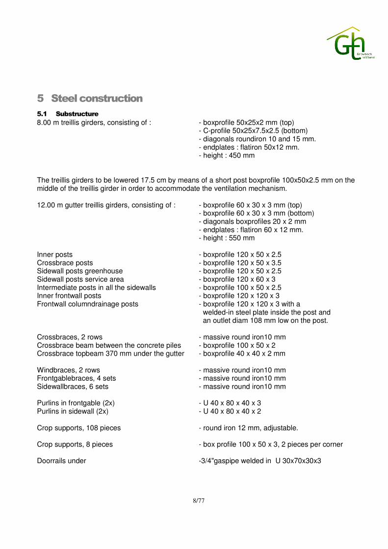
8.00 m treillis girders, consisting of : - boxprofile 50x25x2 mm (top) - C-profile 50x25x7.5x2.5 (bottom) - diagonals roundiron 10 and 15 mm. - endplates : flatiron 50x12 mm. - height : 450 mm The treillis girders to be lowered 17.5 cm by means of a short post boxprofile 100x50x2.5 mm on the middle of the treillis girder in order to accommodate the ventilation mechanism. 12.00 m gutter treillis girders, consisting of : - boxprofile 60 x 30 x 3 mm (top) - boxprofile 60 x 30 x 3 mm (bottom)
- diagonals boxprofiles 20 x 2 mm - endplates : flatiron 60 x 12 mm. - height : 550 mm Inner posts - boxprofile 120 x 50 x 2.5 Crossbrace posts - boxprofile 120 x 50 x 3.5 Sidewall posts greenhouse - boxprofile 120 x 50 x 2.5 Sidewall posts service area - boxprofile 120 x 60 x 3 Intermediate posts in all the sidewalls - boxprofile 100 x 50 x 2.5 Inner frontwall posts - boxprofile 120 x 120 x 3 Frontwall columndrainage posts - boxprofile 120 x 120 x 3 with a
welded-in steel plate inside the post and an outlet diam 108 mm low on the post.
Crossbraces, 2 rows - massive round iron10 mm Crossbrace beam between the concrete piles - boxprofile 100 x 50 x 2 Crossbrace topbeam 370 mm under the gutter - boxprofile 40 x 40 x 2 mm Windbraces, 2 rows - massive round iron10 mm Frontgablebraces, 4 sets - massive round iron10 mm Sidewallbraces, 6 sets - massive round iron10 mm Purlins in frontgable (2x) - U 40 x 80 x 40 x 3 Purlins in sidewall (2x) - U 40 x 80 x 40 x 2 Crop supports, 108 pieces - round iron 12 mm, adjustable. Crop supports, 8 pieces - box profile 100 x 50 x 3, 2 pieces per corner Doorrails under -3/4"gaspipe welded in U 30x70x30x3
9/77
5.2 Provisions onto steel construction
The frontwallposts have the following provisions : - 2 pcs T50 brackets (L = 15 cm) for suspension of the heating tubes. - T50 brackets (L = 50 cm) - strips for screening plates. - strips for supporting the condensation central drainageline. - angle profiles for mounting the purlins. - anchor plates. The sidewallposts have the following provisions : - angle profiles for mounting the purlins. - anchor plates.
6 Aluminium (Alcoa greenhouse systems)
6.1 Roof (Venlo Nova 448)
Ridge 73-355, bars type 73-421, 48 mm high schoven system with solid ridgeconnection. - 1620 pcs 3-pane roofvents dimensions 1200 x (3 x 1122 mm), greenhouse. - 106 pcs 2-pane roofvents dimensions 1200 x (2 x 559 mm), greenhouse. - 84 pcs 3-pane roofvents dimensions 1200 x (3 x 1122 mm), service building The roofvents to be provided with supportbar and rubber closure-profile. All around the roofbars opposite the roofvents to be reinforced, type nr. 73-459. The roofbars to be connected to the ridge by means of half solid ridge connections. 6.2 Stormprotection
The entire roof is stormprotected by means of a solid roofbar/ridge connection, gutterblocks and stainless steel security pins. Additional stormprotection by means of s.c. "half spiders", consisting of massive aluminium diameter 7 mm, 2 pcs per frontgablesection and 1 pc in every outerbay placed above the treillis girder. 6.3 Aluminium frontgables, type slimline
Consisting of : bottomplate, provided with rubber between bottomplate and foundation gablebars, c.t.c. 800 mm, suitable for one layer of glass, to be covered with white artificial strip supportbars, the lower one is narrow and the upper one closes up to the purlin roofendbar, provided with rubber between roofbar and glass Outer gables : gablebars, type nr. 73-514, number: 114 pieces of 4.00 m. Inner gables : gablebars, type nr. 73-514, number: 6 pieces of 4.00 m.

10/77
continued These two inner endgables will be placed in the service building creating an silo- and boiler room. 6.4 Aluminium sidegables, type slimline
Consisting of : bottomplate, provided with rubber between bottomplate and foundation gablebars, c.t.c. 750 mm, suitable for one layer of glass, to be covered with white artificial strip supportbars, the lower one is narrow and the upper one closes up to the purlin roofendbar, provided with rubber between topprofile sidewall and glass Outer gables : gablebars, type nr. 73-514, number: 279.80 m. Inner gables : gablebars, type nr. 73-514, number: 139.90 m (between greenhouse and service area).
7 Doors
7.1 Aluminium doors
6 Insulated aluminium doors. • 2 single sliding doors dimension: 3.00 x 3.00 m (wxh). Entrance of boiler- and silo room. • 2 single sliding doors dimension: 2x 1.75 x 3.50 m (wxh). Greenhouse entrance and exit. • 1 single sliding doors dimension: 3.50 x 3.50 m (wxh). Entrance of service area • 1 single sliding doors dimension: 1.20 x 2.00 m (wxh). Entrance of service area The slidingdoors will be provided with top- or bottomrollers including lock, grip and draughtbrushes. Due to the size of the large doors they will be supplied in 2 parts.
8 Gutters
175 mm wide, galvanised A.P.D. gutter, thickness 3 mm, with drainage to both sides. Due to the gutterlength we will provide so called guided waterflows for the columndrainage The inside of the columndrainageposts to be treated one time with a bitumastic.
9 Drainage
A columndrainage (see steel substructure) with PVC closurecollar and bend 125 mm needs to be mounted and drained off towards a PVC groundmainline. PVC class is 51.
10 Condensation water drainage
Under the gutter an aluminium condensationgutter (half round 40 mm) will be mounted including hangingstrips , endoutlets and fall pipes every 5 gutters, towards a PVC ground main line.

11/77
11 Ventilation mechanism
11.1 Rail mechanism
Rail mechanism, consisting of aluminium pushbars diam. 19 mm (3-pane roofvents 4 pcs) to be mounted on top of the treillisgirder, by means of 3 pcs railconductors per 4.00 m and sendzimir galvanised tube diam 27 x 1.5 mm through the columns. The roofvents will be installed on both sides of the ridge. The greenhouse will be divided in 4 groups. The service building will be ventilated separately in one group. The operation will take place by means of : - total 92 pcs Ridder toothracks, - 60 pcs type TRN-1300-5K - 4 pcs type TRN-1000-5UK - 28 pcs type TRN-520-3K - 8 pcs Ridder motors with mountingplate, type RW-605, including potmeters - 2 pcs Ridder motors with mountingplate, type RW-243, including potmeters The toothracks will be operated by means of 5/4" tube with a thickness of 2.5 mm. Including chaincouplings. The gable end roofvents (only in the greenhouse) are being guided over special stormproof C 50 x 25 x 7.5 x 3 mm, which will be mounted cross under the gutter in the first gable-end section. There will be no gable end roofvents in the corners.
12 Glass and glazing (for your information only)
12.1 Gables
European float glass, width 784 mm in the frontgables and 734 mm in the sidewalls for the single pane gables (outside pane) and covered with artificial coveringstrips. Glassthickness 3.8 - 4.2 mm. The frontgable corners as well as the sidewall corners to be glazed with half panes the first 4.00 m resp 4.50m All panes to be placed on rubber blocks. 12.2 Roof
European float glass dimensions 1122 x 2075 mm, glassthickness 3.8 - 4.2 mm on the roof. To be glazed with aluminium gutteredges. On both gable-ends the first 4.80 m to start with half panes and the outerbays of 4.00 m to be glazed with half panes. The cornersections on the roof to be glazed with 1/4 panes. We urge you to cover the glass immediately after delivery in order to preserve the quality.

12/77
13 General
Rings, bolts and nuts (galvanized), chemical anchors, glazing materials etc. Not included are provisions (outlets in gables, etc.) for heating-, electrical-, screening- and irrigation-installations. The storm protections (half spiders) have to be checked by buyer periodically. We urge you to create sufficient paved space to store our materials, which has to be present at the start of the project. All changes to the contract will be, when possible, confirmed to the buyer before it will be carried out.
14 Standards
Steel construction has been galvanized according NEN and ISO 1461. Roofsystems have been checked according T.N.O. rapport 96-CON-R1711, with corre- sponding Mathcad programs with strength calculations of the connections according : testreport D97B4181 (Venlo Nova 442/448 solid ridge connection) The greenhouse complies with : NEN 3859 2nd print 2004, type A15, zone II NPR 3860 The 10 measures for improving stormprotection of greenhouses according T.N.O. report BI-91-097, dated november 1991. NEN 2nd version, as far as the standing of technics permits. The production and construction of our greenhouses takes place according to BRL 8000 for which a Horti-Q certificate was received. The construction of the greenhouse has been calculated according the latest TNO Casta program version 2.30. The following data were used as an input for the Casta program : - snowload : 400 N/m² - installationload : 70 N/m² - crop load : 150 N/m² - additional load : 130 N/m² (hanging guttersystem) - wind load outside (gable) sections: 615 N/m² inside sections : 461 N/m²

13/77
The greenhouse construction is suitable for the loads of a grow light system, suspended from the treillis girders. If there are, due to local and/or governmental regulations, deviations from the above mentioned assumed loads and components of the greenhouse have to be strengthened, prices will alter accordantly. We recommend a thoroughly check will be made by client if these assumed loads apply for the location of your greenhouse project
- - - - - - - - - - - - - - - -
14/77
SCREEN INSTALLATION
15 Screening installation
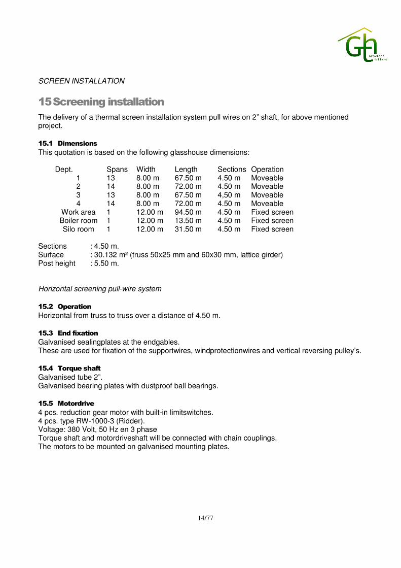
The delivery of a thermal screen installation system pull wires on 2” shaft, for above mentioned project. 15.1 Dimensions
This quotation is based on the following glasshouse dimensions:
Dept. Spans Width Length Sections Operation 1 13 8.00 m 67.50 m 4.50 m Moveable 2 14 8.00 m 72.00 m 4.50 m Moveable 3 13 8.00 m 67.50 m 4,50 m Moveable 4 14 8.00 m 72.00 m 4.50 m Moveable
Work area 1 12.00 m 94.50 m 4.50 m Fixed screen Boiler room 1 12.00 m 13.50 m 4.50 m Fixed screen Silo room 1 12.00 m 31.50 m 4.50 m Fixed screen
Sections : 4.50 m. Surface : 30.132 m² (truss 50x25 mm and 60x30 mm, lattice girder) Post height : 5.50 m. Horizontal screening pull-wire system 15.2 Operation
Horizontal from truss to truss over a distance of 4.50 m. 15.3 End fixation
Galvanised sealingplates at the endgables. These are used for fixation of the supportwires, windprotectionwires and vertical reversing pulley’s. 15.4 Torque shaft
Galvanised tube 2”. Galvanised bearing plates with dustproof ball bearings. 15.5 Motordrive
4 pcs. reduction gear motor with built-in limitswitches. 4 pcs. type RW-1000-3 (Ridder). Voltage: 380 Volt, 50 Hz en 3 phase Torque shaft and motordriveshaft will be connected with chain couplings. The motors to be mounted on galvanised mounting plates.

15/77
15.6 Pull-wire on 2” shaft
Per 8.00 m, 2 pcs. stainless steel (s.s.) pull-wire 7x7 diam. 3,0 mm with alum block. Vertical reversing pulley’s, diam. 4” with dustproof ball-bearings. 15.7 Support- and windprotectionwires
Per 8.00 m. 20 pcs. polyester supportwires diam. 2,5 mm (clear). 10 pcs. polyester windprotectionwires diam. 2,5 mm (clear). The cloth will hang down over an outsidewire with plastic coating and a pvc-tube to prevent cloth-dammage. The supportwires will be held by s.s. –truss-clips. Also the cloth is held by s.s. – truss-clips. 15.8 Leading edge, cloth fixation and cloth
Aluminium leading edge profile (45 mm), with aluminium pull-wire-clamps, s.s. –multiclothclips, s.s – windprotectionwire guides and rubber sealing strips. The cloth at the sidewalls will hang down approx. 50 cm over a p.v.c.-tube and have clothweights and p.v.c. clotheyes per section of 4.50 m - Cloth in greenhouse is PH Super (moveable cloth) Characteristics of the cloth: energy saving ~ 45 %, shadowing ~ 15 % - Boiler room XLS 16 Revolux (flame retardant, fixed cloth) Characteristics of the cloth: energy saving ~ 60 %, shadowing ~ 63 % - Silo room XLS 16 F Fire Break (fixed cloth) Characteristics of the cloth: shadowing ~ 64 % - Work area XLS 16 F Fire Break (fixed cloth) Characteristics of the cloth: shadowing ~ 64 %
15.9 Sealing
Along the sidegables and between the installations fixed canopies in XLS-10-firebreak will be installed. 15.10 Screening of sidewall and frontgables
The outside sidewall and frontgables of the greenhouse will be screened.
16 Gable screening
16.1 Rollscreens between the purlins
Dimensions : 2 pcs. frontgables à 104 m 2 pcs. frontgables à 112 m 1 pcs. sidegable à 139,9 m Drive : 1 powerroll per screen, 12 pcs in total. Cloth : PHL white Characteristics of the cloth: energy saving ~ 60 %, shadowing ~ 100 % Rolltube : alu. rolltube diam. 50mm
- - - - - - - - - - - - - - - -

16/77
HEATING SYSTEM
17 Boiler
For the highest possible efficiency and long life we selected two Crone boilers, type CLW220, each with a capacity of 7.000.000 kcal/h (8.141 kW). These boiler are a three-stage tubular boiler with an eccentric fire canal, suitable for the use of liquid and gaseous fuels. The boilers are be provided with a water-cooled front and the necessary inspection openings, on water- and flue gas side, for proper cleaning. The delivery includes soot brush, rod, inspection-lid, drain off valve and built-in thermo-/manometer. For a long operational life we advise to fill the installation with treated water. 17.1 Chimney
On the smoke box of 2 of the three the boilers a double-walled Cortensteel chimney, will be mounted with a diameter of ø 800 mm. The chimney is insulated with 40mm mineral wool and finished off with sea-air resistant aluminum plating. 17.2 Boiler connections
The supply and return of the boiler ø 273 mm to be connected onto the mainline ø 324 mm from heat storage tank to the header with welding bends and other mounting materials. In the supply and return connection of each boiler a butterfly valve will be delivered and installed. On the supply and return of the boiler 2 pcs. automatic air releases will be mounted and a low water level switch will be mounted on the boiler body.
17.3 Shunt pump
For maintaining an equal temperature in the boiler per boiler a shunt pump will be delivered and mounted between 2 butterfly valves. The capacity of the shunt pump is three times the total contents of the boiler per hour.
17.4 Details of the boiler (per boiler)
Make Crone Type CLW220 gost capacity 7.000.000 kcal/h 8.141 kW Working pressure 0,5 ato Working temperature 110 - 90 °C
Insulation thickness 100 mm, covered with Plastisol plating Boiler base Insulated with rubber Boiler design heating Water contents 14.150 ltr Boiler weight 15.170 kg Heating surface 220 m² Length 6.900 mm Width 2.840 mm Height 3.251 mm

17/77
continued
Supply and return ø 250 mm Drain off ø 65 mm Shunt ø 100 mm Safety device 2 x DN100. Make shunt pump Johnson Type CL100-150 0,75 kW Make butterfly valve AFA Diameter ø 114 mm Diameter chimney ø 800 mm (boilers without condenser) Length chimney 6.000 mm (boilers without condenser) Roof outlet ø 800 mm (boilers without condenser) Rain cover ø 800 mm (boilers without condenser)
18 Burner installation
The delivery of two fully automatic burner make Zantingh each with a capacity of 7.000.000 kcal/h (8.141 kW), complete with electronic gas/air regulation and modulating control. The burner will be placed before the above-mentioned boiler. Including a once-only commissioning of the burner, after the installation of the electrical and gas- connections by a third party are ready. (unless stated otherwise). The burner can run on oil for a short period of time in case of emergency. In that case the capacity of the burner is 100% of the capacity on gas. The burner complies with the current NOx standards i.e. 70mg at 3% O2 and is provided with a gas
plate-mark. (based on Groningen gas specifications)
Complete with the delivery of:
� Front plate. � Fire-resistant inside. � The necessary gas control- and safety devices and thermostats. � Gas street, completely wired. � The necessary mounting materials such as flanges, couplings, thread ends etc. � Switch panel, containing devices and wiring for the described burner. � Light oil part, automatically convertible. � Approx. 12 Meter light oil line ø 1", including filter, valve and return pot. � Fidu-face � CO2 switch is mounted in burner panel (one of the burners) � CO-detector is mounted in burner panel (one of the burners) � Condenser panel is mounted in burner panel (one of the burners) � The required airin- and outlets.
18.1 Technical data
Make Zantingh Type RKB600 ND 6 E G/O Gas Oil Capacity 7.000.000 kcal/h 8.141 kW 7.000.000 kcal/h 8.141 kW
Flame regulation Electronic gas/air regulation modulating
Modulating
Flame protection Ionization Photocell

18/77
continued
Design According VISA Consumption ca. 980 m³/h (Groningen
quality)
Gas pressure 900 mmwk, measured in front of the gas street at maximum capacity
Control reach 1:8 CO2 content at low flame approx. 7% CO2 content maximum capacity
10% a 10,5%
Resistance on flue gas side
1150 Pa
Centrifugal ventilator 18,5 kW frequency controlled Gas pressure 200 mbar on de gas street.
18.2 Gas line
The gas line is not in this offer. 18.3 Oil tank
The oil tank and oil line are not in this offer.
19 Flue gas condenser
Behind one of the above mentioned boiler we will install a condenser. By installing a flue gas condenser the efficiency of the boiler can be improved by 10 to 14%. The cooling down of the flue gasses can be seen as a process in 2 phases:
� Cooling down until the dew point (with natural gas approx. 57°C), whereby the tangible heat is regained.

19/77
continued � Cooling down from the dew point until approx. 40°C, (depending on the temperature of the water
flow through the condenser) whereby the latent heat is regained. This is the heat that’s being released by condensing the vapor, which is present in the flue gasses.
The installation consists of: Condenser block with Cortensteel tubes, provided with extruded aluminum cooling fins. Condense reservoir, made of Cortensteel, as well as the housing. A duct with a built-in valve resulting in the use of only one chimney. The condenser will be mounted onto adjustable supports, making the use of any kind of boiler possible. Control and safety-devices for the condenser according the regulations:
� Switch panel possible integrated in the burner panel. � Pressure switch. � Maximum thermostat. � End switch for the valve. � Flue gas thermometers. � Water thermometers.
19.1 Connections
The condenser will be connected, on the waterside, onto the mixing groups, with the lowest temperature, In this case the return of the heat storage tank. A circulation pump will be placed in the condenser circuit. 19.2 Chimney
On top of the condenser a single wall, non insulated aluminum chimney will be placed.
19.3 Data from the condenser
Make Van Dijk Type CM7501 Design Single with bypass Weight 2.350 kg Capacity condenser 1.180 kW
Capacity Boiler 8.141 kW Heating Surface 639 m2 Length 2.146 mm Width 1.773 mm Height 2.350 mm Diameter chimney ø 700 mm Chimney length 6.000 mm Roof outlet ø 700 mm Rain cover ø 700 mm CO2 connection ø 315 mm Make pump Johnson Type CL100-150 0,75 kW Connection lines ø 159 mm Make of the butterfly valves AFA Heat storage tank Butterfly valve, ø 150 mm
20/77
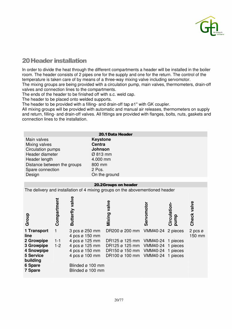
20 Header installation
In order to divide the heat through the different compartments a header will be installed in the boiler room. The header consists of 2 pipes one for the supply and one for the return. The control of the temperature is taken care of by means of a three-way mixing valve including servomotor. The mixing groups are being provided with a circulation pump, main valves, thermometers, drain-off valves and connection lines to the compartments. The ends of the header to be finished off with s.c. weld cap. The header to be placed onto welded supports. The header to be provided with a filling- and drain-off tap ø1" with GK coupler. All mixing groups will be provided with automatic and manual air releases, thermometers on supply and return, filling- and drain-off valves. All fittings are provided with flanges, bolts, nuts, gaskets and connection lines to the installation.
20.1 Data Header
Main valves Keystone Mixing valves Centra Circulation pumps Johnson Header diameter Ø 813 mm Header length 4.000 mm
Distance between the groups 800 mm Spare connection 2 Pcs. Design On the ground
20.2 Groups on header
The delivery and installation of 4 mixing groups on the abovementioned header
Gro
up
Co
mp
art
me
nt
Bu
tte
rfly
va
lve
Mix
ing
va
lve
Se
rvo
mo
tor
Cir
cu
lati
on
-p
um
p
Ch
ec
k v
alv
e
1 Transport line
1 3 pcs ø 250 mm 4 pcs ø 150 mm
DR200 ø 200 mm VMM40-24 2 pieces 2 pcs ø 150 mm
2 Growpipe 1-1 4 pcs ø 125 mm DR125 ø 125 mm VMM40-24 1 pieces 3 Growpipe 1-2 4 pcs ø 125 mm DR125 ø 125 mm VMM40-24 1 pieces 4 Snowpipe 4 pcs ø 150 mm DR150 ø 150 mm VMM40-24 1 pieces 5 Service building
4 pcs ø 100 mm DR100 ø 100 mm VMM40-24 1 pieces
6 Spare Blinded ø 100 mm 7 Spare Blinded ø 100 mm

21/77
21 Transport line
The control of the temperature in the greenhouse will be controlled by means of a four-way mixing valve including servo motor. In order to circulate the heating water throughout the system the mixing groups will be provided with a circulation pump and also main valves, thermometers, drain-off valves and connection lines to the compartments. All mixing groups will be provided with automatic and manual air releases, thermometers on supply and return, filling- and drain-off valves. All fittings are provided with flanges, bolts, nuts, gaskets and connection lines to the installation.
21.1 Details transport line
Main valves Keystone Mixing valves Centra Circulation pumps Johnson Design of the transport line From boiler room to compartment 1 & 2 Ø 273 mm From compartment 1 & 2 to compartment 3 & 4 Ø 219 mm
21.2 Groups on transport line
The delivery and installation of 6 mixing groups on the abovementioned transport line
Gro
up
Co
mp
art
me
nt
Bu
tte
rfly
va
lve
Mix
ing
va
lve
Se
rvo
mo
tor
Cir
cu
lati
on
-p
um
p
1 pipe-rail 1-1 4 pcs ø 125 mm ZR125 ø 125 mm VMM40-24 1 pcs. 2 pipe-rail 1-2 4 pcs ø 125 mm ZR125 ø 125 mm VMM40-24 1 pcs. 3 pipe-rail 1-3 4 pcs ø 125 mm ZR125 ø 125 mm VMM40-24 1 pcs. 4 pipe-rail 1-4 4 pcs ø 125 mm ZR125 ø 125 mm VMM40-24 1 pcs.

22/77
22 Heating system general
The central heating installation has been designed according the “Tichelmann” system, meaning the heating water of each loop travels the same distance throughout the system and therefore will encounter the same resistance everywhere in the system. This is very important for an equal distribution of the temperature. The perimeter heating will be mounted clear from the gables because of possible future use of foil or screening. All suspension materials for main- and distribution lines are galvanized. The installation will be provided with the necessary air releases, drain-off valves and small materials. The following items will be supplied: All necessary tubes, welding bends, air releases ¼", drain-off plugs ¾", air pots, suspension materials (galvanized), fittings, packing- and mounting materials. The welded tubes diameter 51 mm with a wall thickness of 2.25 mm, to be delivered with a guaranteed coldwater pressure test of at least 40 ato. At the place of doors there will be made arches in the lines.
The tubes will be delivered according the following norms: DIN2458/1615 for the measurement. DIN17100 for the density. S235JRG2 for the steel norms. Below mentioned temperature is based on the heat-emission of white painted pipes and when all the heating systems by the below mentioned temperatures. Heating pipes to be delivered unpainted. For delivery of paint see paragraph 39.
22.1 Data
Greenhouse type trellis girder Width of trellis 8 m Post high 5,50 m Sections 4.5 m Roof single glass
Gables single glass Ventilation times 0,5 times Inside temperature + 18°C. Outside temperature - 30 °C. Delta T 48 °C. Wind speed 5m/sec. Screening installation Closed position

23/77
23 Pipe-rail heating
The loops will be connected, as pipe rail to the distribution lines by mean of high-pressure hose, has to be placed by third, on pipe rail supports, which we will deliver The loops will be provided with bumper plates at the gable-end. The installation will be mounted in 4 compartments per greenhouse.
23.1 Data
Supply water 78 °C. Return water 64,3 °C. Number of tubes per bay 10 pcs. Diameter 51 mm Wall thickness 2,25 mm Connections 2 x 1,75 m high pressure hose End piece: Pre bended Pipe rail supports clicked clamp model sendzimir galvanized, to be
placed by a third party. Height 15 cm Center to center 42 cm Distance 1,5 m
23.2 Compartment 1
Number of bays 14 pcs. Bay width 8 m Total length 77,50 m Width of walkway 3 m Distribution lines Ranging from ø 57 mm to ø 152 mm, mounted onto
the gable-end. Mainlines Ø 140 mm mounted underneath the distribution line Gable heating 1 x ø 51 mm

24/77
continued
23.3 Compartment 2
Number of bays 4 pcs. Bay width 8 m Total length 77,50 m Width of walkway 3 m Distribution lines Ranging from ø 57 mm to ø 152 mm, mounted onto
the gable-end. Mainlines Ø 140 mm mounted underneath the distribution line Gable heating 1 x ø 51 mm
23.4 Compartment 3
Number of bays 13 pcs. Bay width 8 m Total length 77,50 m Width of walkway 3 m Distribution lines Ranging from ø 57 mm to ø 152 mm, mounted onto
the gable-end. Gable heating 1 x ø 51 mm Mainlines Ø 133 mm mounted underneath the distribution line Gable heating 1x ø 51 mm Side wall heating 6x ø 51 mm
23.5 Compartment 4
Number of bays 13 pcs. Bay width 8 m Total length 77,50 m Width of walkway 3 m Distribution lines Ranging from ø 57 mm to ø 152 mm, mounted onto
the gable-end. Mainlines Ø 133 mm mounted underneath the distribution line Gable heating 1x ø 51 mm Side wall heating 6x ø 51 mm

25/77
24 Grow pipe heating
The loops will be connected onto the distribution line as an grow pipe by means of high pressure hose and will be hanged by mean of chain and S hooks. The installation will be mounted in 2 compartments per greenhouse:
24.1 Data
Supply water 55 °C. Return water 47.5°C. Number of tubes per bay 5 pcs. Diameter 38 mm Wall thickness 2 mm
Connection 2 x 1,75 m Imag high-pressure hose End piece Bended end piece with 2 x 2,5 m Imag high-pressure hose Suspension Hooks and chain Galvanized, chain no. 27.
24.2 Greenhouse 1 Compartment 1, 3
Number of bays 27 pcs. Bay width 8 m Total length 69,75 m Width of center aisle 3 m Distribution lines ranging from ø 38 mm to ø 152 mm, mounted onto the
gable-end. Mainlines ø 133 mm mounted over the center aisle and alongside
sidewalls 24.3 Greenhouse 1 Compartment 2, 4
Number of bays 27 pcs. Bay width 8 m Total length 69,75 m Width of center aisle 3 m Distribution lines ranging from ø 38 mm to ø 152 mm, mounted onto the
gable-end.
Mainlines ø 133 mm mounted over the center aisle and alongside sidewalls
26/77
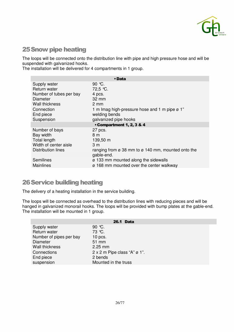
25 Snow pipe heating
The loops will be connected onto the distribution line with pipe and high pressure hose and will be suspended with galvanized hooks. The installation will be delivered for 4 compartments in 1 group.
� Data
Supply water 90 °C. Return water 72,5 °C. Number of tubes per bay 4 pcs. Diameter 32 mm Wall thickness 2 mm
Connection 1 m Imag high-pressure hose and 1 m pipe ø 1” End piece welding bends Suspension galvanized pipe hooks
� Compartment 1, 2, 3 & 4
Number of bays 27 pcs. Bay width 8 m Total length 139,50 m Width of center aisle 3 m Distribution lines ranging from ø 38 mm to ø 140 mm, mounted onto the
gable-end. Semilines ø 133 mm mounted along the sidewalls
Mainlines ø 168 mm mounted over the center walkway
26 Service building heating
The delivery of a heating installation in the service building. The loops will be connected as overhead to the distribution lines with reducing pieces and will be hanged in galvanized monorail hooks. The loops will be provided with bump plates at the gable-end. The installation will be mounted in 1 group.
26.1 Data
Supply water 90 °C. Return water 73 °C. Number of pipes per bay 10 pcs. Diameter 51 mm Wall thickness 2.25 mm
Connections 2 x 2 m Pipe class “A” ø 1”. End piece 2 bends suspension Mounted in the truss

27/77
26.2 Service building greenhouse
Number of bays 1,5 pcs. Bay width 8 m Total length 139,90 m Distribution lines Ranging from ø 51 mm to ø 89 mm, mounted onto the
gable-end. Mainlines ø 83 mm mounted along the sidewalls
27 Irrigation water preheater
The irrigation water preheater consist of a heat exchanger and has the capacity for heating up 12m³/h the irrigation water from 4 to 20 °C. A Johnson circulation pump makes the boiler water circulate through the heat exchanger. Regulation on the secondary side is not included. The heat exchanger to be provided with the necessary valves, thermometers and air releases.
28 Water treatment / partial flow filter
For the water treatment an installation with a partial flow filter and water softener, with a capacity of 10 m³.hr., will be delivered. The partial flow filter will filter the pollution, floating parts and for instance magnetite. A part of the main flow shall be pumped through the filter, where the pollution in a polypropylene bag will be filtered. A magnet will catch the magnetism parts as magnetite. To prevent the shaping of magnetite the Ph-level of the water has to be 9,8. The partial flow filter will be mounted on the underside of the return header and can be closed with two butterfly valves. A separate pump take care of the circulation of the water. With two manometers the grade of pollution of the filter can be seen. Behind the partial flow filter a water softener is placed this water softener can soften the water of a filled installation. To fill the installation with civil water is the best choice. Because of the high hardness in the water the softening is necessary. This way you will prevent that the hardness in the water deposited on the hottest parts of the installation (the fire tube of the boiler). The softener works on basis of changing off ions whereby the “hard” ions so as calcium and magnesium will be changed with “soft” ions so as sodium. For the adding of chemicals a dose pump will be delivered. The chemicals, which are to be used for the water treatment, depends the quality of the water used for filling the heating installation. When you send us a water sample of the water, which will be used for filling the heat distribution system, then we will provide you free of charge with a report, which chemicals you need to buy locally for using the water treatment installation.

28/77
With the water softening system salt has to be used to soften the water going into the heat distribution system. The amount of salt required for softening the water depends on the quality of the water as will be used by you for filling. The salt, which should be used, is of the kind as used in dish washers. It should not give problems to obtain this kind of salt locally.
29 Heat storage installation
The delivery of a heat storage installation for CO2 dosing according the below mentioned description. 29.1 Storage tank
The delivery of a vertical storage tank, without steal treatment with a manhole on the roof and a manhole in the hull. The tank to be placed directly next to the boiler house on a concrete floor. Mounting/assembly of the vertical tank to be executed under supervision. 29.2 Connections
The tank, boiler and header will be connected according the “Open buffer” principal. Inside the tank distribution tubes including holes must be mounted as supply and return. The supply- and return connections of the tank to be hooked up onto the boiler mainlines. A motorized butterfly valve will delivered to be mounted in the boiler supply line. Also a motorized butterfly valve will be delivered to be mounted in the return line to the tank. Per boiler a mixing valve will be placed to heat the return water from the tank. For circulating the water through the boiler per boiler a frequency controlled Johnson pumps needs to be delivered. The installation is provided with a minimum and maximum pressure device.
29.3 Technical data
Total area 30.132 m2 CO2-dosingnorm 12 m3 / h / 1000 m2 Maximum and minimum temperature of the heat storage tank
95 – 40 ºC
Minimum temperature of the boiler 65 ºC Diameter tank ø 8,74 m Total height of the tank 10 m Content of the tank 600.000 liter Hull 5 mm Bottom 6 mm Roof 5 mm Maximum overpressure 56 mbar Maximum under pressure 6 mbar Lines to and from the tank ø 323 mm Motor valve in boiler mainline ø 300 mm make AFA Butterfly valve in the return of the tank ø 250 mm make AFA
System pump CLB200-200 3,0 kW make Johnson, frequency controlled
Mixing valve DR200 make Centra Butterfly valves mixingvalves ø 200 mm make AFA

29/77
30 Insulation
30.1 Insulation boiler house lines
The delivery of prefab insulation to insulate the hot water lines in the boiler house with mineral wool 30mm and finish off with aluminum cladding with a thickness of 0.6mm.
30.2 Calculated
15,00 m tube 4 pcs weld caps ø 508 mm Insulation thickness 30 mm 24 m tube 7 pcs bends ø 323 mm Insulation thickness 30 mm 18 m tube 8 pcs bends ø 273 mm Insulation thickness 30 mm 25,60 m tube 8 pcs bends ø 133 mm Insulation thickness 30 mm 12,80 m tube 8 pcs bends ø 114 mm Insulation thickness 30 mm 1 pcs mixing groups 150 ø 159 mm Insulation thickness 30 mm 4 pcs mixing groups 125 ø 133 mm Insulation thickness 30 mm 1 pcs mixing groups 100 ø 114 mm Insulation thickness 30 mm 1 pcs mixing groups 80 ø 89 mm Insulation thickness 30 mm 1 pcs mixing groups 50 ø 60 mm Insulation thickness 30 mm 2 pcs spare 100 ø 114 mm Insulation thickness 30 mm
30.3 Insulation transport lines
The delivery of prefab insulation to insulate the transport lines and mixing groups on the transport lines with mineral wool; 30mm and finish off with aluminum cladding with a thickness of 0.6 mm.
30.4 Calculated
280 m tube 10 pcs. bends ø 140 mm Insulation thickness 30 mm 280 m tube 10 pcs bends ø 127 mm Insulation thickness 30 mm
30.5 Insulation heat storage
The delivery of prefab insulation to insulate the heat storage tank with mineral wool 200mm and finished off with plastisol/aluminum cladding with a thickness of 0.8mm. The delivery of prefab insulation to insulate the lines with mineral wool 30/50mm and finished off with aluminum cladding with a thickness of 0.6mm.
30.6 Calculated
1 tank ø 8,74 m Height 10 m Insulation thickness 200 mm
48 m tube 10 pcs bends ø 323 mm Insulation thickness 50 mm
25,60 m tube 12 pcs bends ø 219 mm Insulation thickness 30 mm
31 Paintwork
White/grey paint will be delivered to paint the tubes after mounting including washcloths, turpentine and linseed oil.
32 Boiler room heating
On the header spare connection on the header a separate mixing group for the heating of the boiler room will be delivered. The boiler room heating will be used for the heating of the air which is needed by the burners. The heaters will be provided with an air outlet and thermostat.
- - - - - - - - - - - - - - - - - - - -

30/77
33 Electrical installation
Our calculation is based on the following general data: Power supply : 230 – 400 Volt, + or – 5 %. Frequency : 50 cycles. Dimensions greenhouse : 216,00 x 140,00 mtr. - assumed project altitude : 1.050 - 2.340 m. - assumed max. ambient temp. : 40 oC. All electrical systems and equipment will be delivered according Dutch regulations for electricity, named NEN 1010. Not included are the supplies of a ground wire and/or neutral conductor. POWER DISTRIBUTION Main distribution panel board: For the total greenhouse project, we offer you a polyester main distribution panel board, located in the service building. The complete electrical installation will be connected through this main distribution panel board. Following electro technical regulations NEN 1010, this main distribution panel board will be divided in two sections. A 400V, three phase section and a 230V, single phase section. Earth leakage protection switches will protect general use outlets, 230V and 400V. The main distribution panel consists of: Section with circuit breakers 400V, 3 phase: 1 pc. main switch 4-poles, main-off-generator, 250 Ampere; 1 pc. breaker 100 Ampere for greenhouse panels (knife blade); 1 pc. breaker 32 Ampere for switch panel irrigation unit 1; 1 pc. breaker 16 Ampere for switch panel crop-cooling unit; 1 pc. breaker 16 Ampere for switch panel hand watering unit; 1 pc. breaker 16 Ampere for switch panel HP-UV unit; 1 pc. breaker 50 Ampere for switch panel boiler 1; 1 pc. breaker 50 Ampere for switch panel boiler 2; 1 pc. breaker 32 Ampere for CO2-set 1; 1 pc. breaker 63 Ampere for switch panel circulation pumps (knife blade);
1 pc. breaker 16 Ampere for boiler room heaters (on own thermostat); 4 pc. breaker 16 Ampere for outlets 400V for general use; 1 pc. breaker 35 Ampere for supply of following 230V section. Section with circuit breakers 230V, single phase: 1 pc. main switch 4-poles, main-off-generator, 63 Ampere; 1 pc. breaker 16 Ampere for computer; 4 pc. breaker 16 Ampere for lighting; 4 pc. breaker 16 Ampere for outlets 230V; 1 pc. breaker 16 Ampere for spare. Unless mentioned otherwise, circuit breakers are of the type: automatic. The main distribution panel will be delivered with all necessary connection materials and will be mounted on a white, wooden board. The main distribution panel is prepared for connection of a generator set.

31/77
Note: The supply cable from the transformer / generator to this main distribution panel board to be supplied by Client.
33.1 Electrical installation greenhouse
Greenhouse panels: In the greenhouse, which is divided into 6 compartments, all motors and pumps will be connected to a central switch panel. One switch panel per 2 compartments. (in total 3 pc.) Each sheet steel panel will be mounted near the concrete path and contains: 1 pc. main switch 4-poles, main-off, 40 Ampere; 4 pc. switch gear for ventilation motor 400V; 2 pc. switch gear for top screen motor 400V; 4 pc. switch gear for gable screen motor 230V; 1 pc. supply for drain pump 400V; 4 pc. switch gear for heating pump 400V; 4 pc. switch gear for mixing valve 24Vac; 1 pc. transformer 230V/24Vac; 1 pc. breaker 16 Ampere with earth leakage protection for outlets 400V; 1 pc. breaker 16 Ampere with earth leakage protection for outlets 230V. Unless mentioned otherwise all motors are 1 speed and max. 2,2kW. The switchgear, where necessary, consists of a motor protector, a contactor, a ‘manual/automatic’ switch and alarm-/run pilot lights. The greenhouse panel will be delivered with all necessary connection materials and will be mounted on a white, wooden board. Electrical materials greenhouse: For the greenhouse we offer you the following materials: 140 mtr. galvanised cable channel 45 mm wide; 230 mtr. galvanised cable channel 70 mm wide; 200 mtr. galvanised cable channel 120 mm wide; 5 pc. outlet 230V, 2 poles; 5 pc. outlet 400V, 4 poles; 1 pc. light switch; 6 pc. strip light 1x36W, incl. tubes; 3 pc. white, wooden mounting board. All materials are dust-tight and splash proof (IP54).
33.2 Electrical installation service building
Circulation pump panel:

32/77
In the boilerhouse all motors and pumps will be connected to a switch panel. This sheet steel panel contains: 1 pc. main switch 4-poles, main-off 80 Ampere; 2 pc. switchgear for shunt pump 380V; 1 pc. switchgear for condenser pump 380V; 2 pc. switchgear for buffer fill pump 380V, frequency controlled (7,5 kW); 2 pc. switchgear for boiler shock pump 380V; 2 pc. switchgear circulation pump 380V for grow pipe heating; 4 pc. switchgear circulation pump 380V for tube rail heating; 1 pc. switchgear circulation pump 380V for irrigation water pre-heating; 1 pc. switchgear circulation pump 380V for boiler room heating (on own thermostat); 1 pc. switchgear circulation pump 380V for snow pipe heating; 1 pc. switchgear circulation pump 380V for heating service building; 1 pc. switchgear circulation pump 380V for partial filter installation; 9 pc. switchgear for mixing groups 24Vac; 9 pc. switchgear for mixing valve 24Vac; 2 pc. switchgear for mixing valve 220Vac; 1 pc. breaker 16 Ampere for pressure installation; 1 pc. breaker 20 Ampere, frequency drive for buffer fill pump (7,5 kW); Unless mentioned otherwise all motors are 1 speed and max. 2,2kW. The switchgear, where necessary, consists of a motor protector, a contactor, a ‘manual/automatic’ switch and alarm-/run pilot lights. The circulation pump panel will be delivered with all necessary connection materials and will be mounted on a white wooden board. 33.3 Frequency drives:
For variable speed control of the buffer fill pumps, a frequency drive will be applied. The drives are dust-tight and splash proof (IP54) and are suitable for mounting next to the circulation pump panel. The pump speed regulation is based on the climate computer calculations. The pump will be connected with an E.M.C.- proofed cable and cable fittings: 2 pc. ABB frequency drive 380V, 7,5kW, E.M.C. class A; 100 mtr. E.M.C.- proofed cabling 4 x 4 mm², class A. All materials for connection of the following equipment, in the boilerhouse, will be delivered: 2 pc. boiler installation; 1 pc. expansion system; 1 pc. CO2-set; 18 pc. circulation pump as described under circulation pump panel. Electrical materials service building: For the service building we offer you the following materials:

33/77
20 mtr. galvanised cable channel 45 mm wide; 200 mtr. galvanised cable channel 70 mm wide; 170 mtr. galvanised cable channel 120 mm wide; 11 pc. outlet 220V, 2 poles; 12 pc. outlet 380V, 4 poles; 7 pc. light switch; 36 pc. strip light 2x58W, incl. tubes;
1 pc. motor reverse switch box double 400V for vent motors, incl. motor protector;
1 pc. motor reverse switch box single 400V for screen motors, incl. motor protect; 3 pc. white, wooden mounting board.
All materials are dust-tight and splash proof (IP54). We assume that all strip lights can be suspended from the building structure. Alarm signalling display: For detecting and signalising of occurring alarms of the project, we offer you an Oct-alarm with text display –T8S, telephone dialler, including: 1 pc. multiple tone sounder. In total it is possible to connect 8 alarms, for example the following: - Greenhouse switch panel; - Boilers and CO2 - set; - Circulation pumps; - Irrigation units; - Integer computer; - etc. Included is all low-voltage cabling and connection materials regarding the Oct-alarm. Note: Assumed is that a telephone line is present at site, located near the Oct-alarm. CABLE CHANNELS For installation of the cabling in an efficient manner, cable channels will be delivered as quoted. Cable channel will be used, where 3 or more cables 220/400 Volt are concentrated. The channel is sendzimir galvanised and has a material thickness of at least 1 mm. Channels shall be supported in a proper way to prevent bending. On places were the channels will be connected with each other, or where channels go in other directions, prefab help pieces will be used. Horizontal channels on a lower level than 1,6 mtr. from soil level will be provided with a cover and cover clamps. Channels will be considered full at 80 % capacity. CABLING

34/77
Our quotation includes all cabling to equipment as described in this offer. These cables are of tropical design and of the type YMvK. Only the supply cables from main distribution panel to the sub distribution panels / switch panels, are armoured and of the type NYCWY. These NYCWY cables should be dug in at a minimum depth of 0,6 mtr. Cables coming out of a cable channel and going downwards to equipment, as for example an outlet, will be protected through a hostalyte pipe fixed with pipe clips. Loss of voltage on cables 230/400 V will normally not exceed 10 %, starting from main distribution panel board to all electrical equipment.
34 Recirculation fans
In support of air flow in the greenhouse to achieve a more equal climate, we offer you an installation with recirculation fans, serial mounted. For speed control of the fans will be delivered speed controllers which are suitable for mounting next to the greenhouse switch panel. The fans will be suspended from the trellis by means of suspension brackets. This installation consists of: 48 pc. Multifan recirculation fan, type TB4E40Q, specifications:
- 230 Watt/ 230 Volt / 50Hz/ 1.1 Ampere; - capacity 5.050 m3/h; - throw 45 mtr;
96 pc. suspension bracket / chain; 4 pc. speed controller; 96 pc. connection box; 2 pc. switchgear for recirculation fans, in greenhouse switch panel; 1 pc. computer control program. This includes all necessary cabling and fixation materials.

35/77
35 Priva Integro computer system
The computer system will be delivered in a wall enclosure (58x88x23) which is divided in a connection -, processor - and supply section. The enclosure contains:
1 pc. CPU board 9504 with one serial RS232 printer port, two serial RS232 communication ports, one thin ethernet port and one alarm output;
1 pc. flash memory; 1 pc. power supply unit 300VA; 1 pc. battery pack; 1 pc. internal terminator board for I/O network. For controls and measurements extra hardware is built in: 5 pc. module 16xan.in/4xdig.in/32xdig.out AC; 1 pc. module 0xan.in/4xdig.in/64xdig.out AC; 1 pc. module for meteorological station; 1 pc. module internal terminator board 9550 (beginning/end). Additional hardware: 1 pc. box with 1 EC/pH-module + power supply 24VDC/conn.print 9511; 1 pc. box with 2 EC/pH-modules + power supply 24VDC/conn.print 9511; 1 pc. thin ethernet materials. Operation in office: 1 pc. workstation, consisting minimal of: - Pentium 4GHz/40GB; - intern 256MB; - sound card (speakers extra on request) - cache 512 kB; - 3 ½ “ disk station; - CD Rom 48 speed; - Windows XP; - SVGA monitor 17”; - Qwerty keyboard; - mouse incl. pad; - PC Anywhere; - User manual. 2nd operation in irrigation room: 1 pc. Integer serial keyboard with CRT for monochrome monitor; 1 pc. VGA 15" monochrome monitor 15" for CRT connection; 1 pc. box with supply unit 24VDC/connection board 9511 connection. Reporting: 1 pc. printer Swift 120D+ serial, 5m cable, paper, console; 1 pc. external modem.
36/77
Accessories: 1 pc. user manual (printed) - English. General programs: 1 pc. Supervision; 1 pc. Horti office; 1 pc. heat management, co-ordination of heat demand and production; 1 pc. heat transport line with 1 on/off pumps and mod. mixing valve; 2 pc. heat transport line, frequency controlled pump/mod. mixing valve; 1 pc. CO2 management, co-ordination of CO2 demand and production; 1 pc. CO2-transport for switching of central CO2 dosing fan; 2 pc. boiler with modulating burner control; 2 pc. CO2 control on burner system; 1 pc. CO2 monitor input for max.12 sampling valves on selector system; 2 pc. switching function with on/off output, type 2; 2 pc. universal servo control for mod. 3-point control with feedback. Compartment related programs: 5 pc. climate compartment; 5 pc. measuring box with protection and alarm functions; 5 pc. heating control; 11 pc. heating net with one or two on/off pumps/modulating mixing valve; 5 pc. ventilation control; 10 pc. vent motor control with meas. of vent position or running time; 1 pc. CO2 control with high/low level; 5 pc. curtain control with shading/energy function; 8 pc. curtain control with slave and side-wall function; 15 pc. curtain motor control based on running time; 6 pc. crop protection with four periods. Irrigation related programs: 1 pc. irrigation valve group; 1 pc. starting program; 1 pc. irrigation main supply line, connecting valves/tanks to water system; 1 pc. water system; 1 pc. liter counter input; 1 pc. mixing tank control with measurement of 4 levels: minimum, start, stop, maximum; 1 pc. EC measurement/pre-control without level meas. in drain tank; 1 pc. filter back washing for 1 filter; 1 pc. EC/pH control without dosing channels; 4 pc. fertilizer stock tank (only required in case of stock tank selection); 2 pc. dosing channel for EC or pH control; 1 pc. control program for HP-UV vialux sterilizer; 3 pc. water treatment recipe; 1 pc. EC/pH-measurement and quantity measurement in drain sump; 15 pc. irrigation valve.

37/77
Propagation area related programs:
General programs: 1 pc. heat transport line with 1 on/off pumps and mod. mixing valve; 1 pc. assimilation lighting program with starting conditions; 2 pc. assimilation lamp group with on/of control of assimilation lighting.
Irrigation related programs: 1 pc. irrigation valve group; 1 pc. starting program; 1 pc. irrigation main supply line, connecting valves/tanks to water system; 1 pc. water system; 7 pc. irrigation valve. Sensors and equipment: 1 pc. water temperature sensor, shaft 80mm for hot water;
The computer system quotation is including all cabling from the computer to all equipment as sensors and switch panels. Sensors and equipment: 1 pc. meteorological mast, consisting of: - Kipp radiation light sensor CM3-P in aluminium housing; - wind velocity sensor in aluminium housing; - wind direction sensor in aluminium housing; - outside temperature sensor in aluminium housing; - rain sensor in aluminium housing.
20 pc. water temperature sensor, shaft 100mm for hot water; 4 pc. measuring box T + RH with water tank, aspirator fan 24VAC, connecting materials; 1 pc. hygrowick 25cm for wet bulb humidity measurement, 10 pieces; 1 pc. measuring box T with aspirator fan, connecting materials; 10 pc. vent position indicator 90 degrees, potentiometer 1kOhm-lin; 1 pc. CO2-monitor 250E, 0-3000ppm, water trap, dust filter, manual; 1 pc. set of 2 cans gas for calibration of zero and span range. The computer system quotation is including all cabling from the computer to all equipment as sensors and switch panels. For controlling the climate- and irrigation conditions in the nursery, we offer you these additional hardware and programs: 35.1 Extension of the CPU cion panel:
1 pc. module 0xan.in/4xdig.in/64xdig.out AC;

38/77
35.2 CION panel EC/pH mounted on the irrigation unit, existing of:
1 pc. box with 1 EC/pH-module+power supply 24VDC/conn.print 9511. 35.3 Irrigation related programs:
1 pc. irrigation valve group; 1 pc. starting program (including transpiration sum); 1 pc. water system; 1 pc. liter counter input; 1 pc. EC control without dosing channels; 1 pc. dosing channel for EC or pH control; 1 pc. water treatment recipe; 9 pc. irrigation valve.
36 Lighting system for young plant area
Artificial light increases the yield by improving both the rate of growth and the quality. Therefore a special range of luminaries has been developed for use in providing photosynthesis lighting. The luminaries are of lightweight construction, so as to avoid too much strain on the structure of the greenhouse, while their small size block out very little daylight. The specially computed high-quality mirror reflector ensures a remarkably high luminary output ratio. For artificial light for a total surface of approx. 4.914 m², we offer you an installation in the greenhouse, which is divided in 2 ‘light sections’. The total lighting installation consists of 260 pc. assimilation fixtures. The fixtures will be (shifted) suspended from a profile, hanged on the trellis, parallel with the gutter, in total 14 rows. The lighting installation in the greenhouse consist of: 260 pc. fixture, type HS2000 DEEP/MIDI/WIDE 600W HPS, 400V; 260 pc. 600 Watt bulb; 260 pc. fixture -suspension bracket; 1300 mtr profile, 45 x 45 mm; 300 pc. profile -suspension bracket; 2 pc. switch panel, existing of 16 groups. Note - Average light level: 4.000 Lux. Switch panels: For each light section in the greenhouse, will be delivered a polyester panel and is mounted near the in the centre of the light section. Each switch panel contains: 1 pc. main switch 4-poles, main-off, 250 Ampere; 16 pc. circuit breaker 16 Ampere, 1 pole; 16 pc. switchgear. The switchgear consists of a contactor and a ‘manual/automatic’ switch.

39/77
The switch panel will be delivered with all necessary connection materials and will be mounted on a white, wooden board. Additional electrical materials: Main distribution panel board: For the artificial lighting in the propagation area the main distribution panel will be extended with the following: 1 pc. breaker 160 Ampere for assimilation light panel 1 (knife blade); 1 pc. breaker 160 Ampere for assimilation light panel 2 (knife blade). Cable channels: For installation of the cabling in an efficient manner, cable channels will be delivered as quoted. Cable channel will be used, where 3 or more cables 230/400 Volt are concentrated. The channel is sendzimir galvanised and has a material thickness of at least 1 mm. Channels shall be supported in a proper way to prevent bending. On places were the channels will be connected with each other, or where channels go in other directions, prefab help pieces will be used. Horizontal channels on a lower level than 1,6 mtr. from soil level will be provided with a cover and cover clamps. Channels will be considered full at 80 % capacity. For the lighting installation in the greenhouse, we offer you the following cable channel: 125 mtr. galvanised cable channel 120 mm wide. Cabling: Our quotation is including all (supply) cabling to the switch panels and fixtures. These cables are of tropical design and of the type YMvK. Only the supply cables from main distribution panel board to the switch panels, are armoured and of the type NYCWY. These NYCWY cables should be dug in at a minimum depth of 0,6 mtr. The size of the cables is based on a minimum loss of voltage. The supply cables from the switch panels are connected to the main distribution board, located within the service building area.
40/77
37 Drip irrigation system
37.1 Technical data of system:
Crop and growing method : tomatoes on suspension gutters. Plant rows per bay : 5 per bay of 8,00 mtr.(V-system) Plant distance : 25 cm. Number of plants per m² : 2.5 plants/m². Total number of plants : 75.600 Capacity of drippers : 3,0 ltr/hour. Capacity of drip irrigation system : 2.5 ltr/m2/hour. Number of valves irrigating simultaneously : 2 pc. Number of drip tubes per bay : 5 pc. Diameter and location sub main line : 63 mm, along gable. Diameter and location main line : 160 mm, along path. Type and location of pump unit : mixing tank principle, in service building. Specification of materials Drippers and tubing: 18.900 mtr. PE-tube 25 mm, pre punched at 25 cm;
75.600 pc. Self-closing pressure-compensated drippers, cap. 3,0 ltr/h, complete with spaghetti 60 cm and stick angle;
272 pc. endset for PE 25 mm complete with screw cap. Assembling of drippers on PE 25 mm tube is excluded Note: Advantages Self-closing pressure-compensated drippers:
- Pressure compensated dripper, exclusively designed to “lock” itself at the end of an irrigation cycle. - Prevents water drainage from the system and eliminates the necessity to refill the system at the start of the next irrigation cycle. - Prevents the collection of run-off water at the bottom of irrigation slopes. - Very accurate performance and uniformity. Network of mains: 250 mtr. PVC pipe 160 mm (main line), 10 bar; 6 pc. electric valve 2", 24 V, plastic, complete with flow control; 6 pc. pressure gauge, glycerine filled, 0-6 bar; 3 pc. PVC tap valve 1", complete with Geka quick joint; 6 pc. PVC ball valve 90 mm, for shut of the valve set; 6 pc. PVC ball valve 75 mm, as a bypass of the electrical valve; 430 mtr. PVC pipe 63 mm (submain lines); 420 mtr. PVC pipe 110 mm (transport line to submain line located along the gable); 12 pc. PVC union 75 mm; 272 pc. PVC Tee 63 x 32 x 63 mm; 272 pc. PE riser 25 mm, length ± 600 mm; 272 pc. PVC elbow PE25 x PE 25 mm; All necessary PVC fittings for main- and submain lines are included. All necessary low voltage cabling for electric valves is included.

41/77
Pump unit, based on mixing tank principle: Pump unit has a maximum capacity of 75 m3/hour based on a nursery-area of 30.000 m². Pump unit built-up on a stainless steel frame and consisting of: 1 pc. supply pump / fresh water pump, brand Grundfos, type CR complete with check valve and butterfly valve; 1 pc. filling valve 110 mm complete with mechanical level switch for filling mixing tank; 1 pc. polyester mixing tank 1.500 ltr, including drainvalve, provided with lid; 1 pc. level control in mixing tank including an high-low level alarm; 1 pc. drip irrigation pump, brand Grundfos, type CR ; 1 pc. softstarter for drip irrigation pump, built in switchpanel; 1 pc. PVC check valve built-in supply line of the drip irrigation pump; 2 pc. maximum temperature safety; 3 pc. dosing pump, type EMA, for dosing of "so called" A- and B-fertilizer and acid or lye solutions; 2 pc. EC-probe, excluding interface; 2 pc. pH-probe, excluding interface; 1 pc. sand filter, coated steel, with a maximum capacity of 90 m³/h, working- pressure 10 bar. The sand filter is provided with automatic backwash, consisting of: - 3 pc. electrical valves; - 1 pc. PVC check valve; 1 pc. fine filter 4", coated steel, perforation 130 micron, installed after sand filter; 4 pc. pressure gauge 0-6 bar, glycerine filled; 1 pc. liter counter, type Arad with pulse head, 1 pulse per 10 ltr, capacity 90m3/h, installed in supply line to the nursery; 1 pc. butterfly valve 160 mm, installed in supply line to the nursery; 1 pc. switch panel, for control of pumps, level switches, etc; 1 pc. white wooden cabinet for assembling of panel and interfaces.
Fertilizer tanks, for pumpunit: 4 pc. polyester fertilizer tank for "A" and "B" fertilizers, each contents 2.200 ltr, rectangular; 2 pc. polyethylene tank for an acid and lye solution, provided with lid, content 200 ltr. PVC suction lines from fertilizer tanks to the pump unit are included. PVC filling line to the fertilizer tanks provided with valves are included.
42/77
38 Overhead irrigation system - propagation area
Technical data of system: Irrigation lines : made of PVC 32 mm white; Number of lines : 2 per bay of 8,00 mtr, high installed; Sprinklers : upside-down sprinklers, cap. 160 ltr/hr with LPD; Sprinkler distance : c.t.c. 150 cm; Number of lines per valve : 2; Diameter and location sub main line : PVC 50 mm, white, in the middle of the
bay, high installed; Diameter and location main line : PVC 110 mm, in the middle of the bay, partial high installed; Type of pump unit and location : existing mixing tank unit in pump room Specification of materials
Irrigation lines: 1.275 mtr. white PVC pipe 32 mm, drilled at 150 cm; 870 pc. upside-down sprinkler, capacity 105 ltr/min at 2 bar; 870 pc. non leakage device; 14 pc. PVC tee/elbow set 32 mm; 28 pc. PVC endset 32 mm, complete with screw cap; 28 pc. 2/3 union 32 mm; 1.700 pc. galvanised wire hook, length 35 ~ 40 cm; 1.500 mtr. galvanised wire no. 12; 28 pc. galvanised wire-strainer. Submain lines: 60 mtr. white PVC pipe 50 mm.
All necessary PVC Tee's, elbows and fittings are included. All necessary galvanised hooks are included.
Main line: 60 mtr PVC pipe 110 mm, white, high installed, 10 bar; 200 mtr PVC pipe 110 mm, grey, 10 bar; 7 pc. elec. valve 1.½”, 24 Vac; 7 pc. T-piece 110 x 50 x 110 mm; 7 pc. PVC union 50 mm.
All necessary PVC bends, tees, fittings and cabling are included. All necessary galvanised hooks are included.
Additional materials pump unit: 1 pc. level stick 0 – 100% in mixing tank, for level reduction control, including an high-low level alarm; 1 pc. pre-rinse valve 1 ½”, 24 Volt; 4 pc. PVC fertilizer-selection valves 20 mm 24 V for an automatic choice between solution A1 / B1 and A2 / B2; 2 pc. polyester fertilizer tank for "A" and "B" fertilizers, each contents 600 ltr, round.
PVC suction lines from fertilizer tanks to the pump unit are included. PVC filling line to the fertilizer tanks provided with valves are included.
43/77
39 Drainwater collection and re-using
For catching and collecting drain water, we offer you a drain water collection system. The system is based on a drain percentage of 35 %. Along the gable a PVC collection pipe ø 125 mm dug in with slope and connected to a polyester drain collection tank. Per bay of 8,00 mtr. 5 pc. suspended gutters connected to the PVC collection pipe with PVC saddles, PVC pipe and flexible gutter connections. A drain water collection tank 1.450 ltr, mounted underground, along the pathway, complete with PVC overflow with maximum 3,0 mtr. PVC pipe ø 125 mm. On the drain collection tank a polyester reinforced lid will be mounted complete with hinge. The drain collection tank provided with a filter pipe, filtration 3 mm, to collect dirt in the drainwater. Material specifications: Pipe network and collection tank: 610 mtr. PVC pipe 125 mm (class 51) including 3,00 mtr. pipe for the overflow; 272 pc. flexible gutter connections; 150 mtr. PVC pipe 50 mm; 272 pc. PVC saddles 125 x 50 mm; 1 pc. polyester drain collection tank, contents 1.450 liter, ø 1,40 mtr, height 1,90 mtr; 1 pc. polyester reinforced lid provided with hinge. All necessary PVC appendages and fastening materials are included. Drain pump and return pipe line: For pumping the drainwater to the drain buffer tank, a drainwater pump Lowara type SHE will be located near the drain collection tank. The return pipe ø 90 mm to the drain buffer tank, provided with a fine filter, a liter counter and an EC measurement sensor. The return pipe will be provide with 2 valves to select between the drain buffer silo and sewer. 1 pc. PVC suction pipe 90 mm; 1 pc. PVC valve 90 mm; 1 pc. drainwater pump Lowara type SHE, cap. 26 m3/hour, with an head of 18 m; 1 pc. PVC non-return valve 90 mm; 1 pc. coated steel fine filter 3" with a filtration of 300 micron; 1 pc. coated steel liter counter 3" provided with a pulse contact(1 pulse per 10 liter); 1 pc. EC-measurement sensor, excluding interface; 150 mtr. PVC return pipe 90 mm, to the drain buffer tank; 1 pc. PVC valve 90 mm; 2 pc. PVC valve 90 mm, to select between drain buffer tank or sewer; 1 pc. switch panel, for supply / controlling the pumps and the level switches; 3 pc. level switch, for a minimum alarm, on/off level and maximum alarm. All necessary PVC appendages and fastening materials are included. All low-voltage cabling to connect the liter counter and the level switches is included.

44/77
Drain buffer tank with suction line: For the storage of the untreated drainwater, a galvanised corrugated plate drain buffer tank will be located in the pump room. The content of this drain buffer tank is based on a buffer capacity of one day and a drain quantity of max 4,5 l/m²/day. 1 pc. galvanised corrugated plate drain buffer tank of following dimensions:
content : 131 m3; diameter : 7.04 mtr; height : 3.38 mtr.
1 pc. EX black liner, thickness 0,5 mm, for aforementioned tank dimensions; 1 pc. polyester protection blanket including fastening strip, for aforementioned tank
dimensions; 1 pc. PVC black anti-algae cover, mounted on top of the tank; 45 pc. tiles 30 x 30 cm as foundation. 2 pc. level switch for on/off switching of the sterilizer. Note: Please consider with installation of the water storage tank a minimum load of the surface of 1.000 kg/m2 for each meter tank height!! The strength analysis of the tank construction is based on a maximum buried depth of 80 cm. The tank has to be placed not lower than 20 cm. above ground water level. Overflow: The drain buffer tank provided with an overflow ø 110 mm, till 12 meter outside the tank. Suction line to pump unit: A suction line 125 mm with a total length of 30 mtr. from the aforementioned drain buffer tank connected to the pump unit, mentioned in item 1. Applying the following materials: 30 mtr. PVC pipe 125 mm; 1 pc. PVC filter pipe 125 mm; 1 pc. PVC butterfly valve 125 mm; 2 pc. level switch for a minimum level and a maximum level alarm. All necessary PVC appendages and fastening materials are included. All low-voltage cabling to connect the level switches is included. Mixing drainwater and freshwater: For re-using drainwater, it will be mixed up with mains/rain water. The suction line of the drip irrigation pump will be provided with a double butterfly valve 125 mm, with servomotor 24 V. On the principle of the EC value the butterfly valve will be controlled by means of an EC measurement sensor, mounted in the supply line. 1 pc. PVC double butterfly valve 125 mm, provided with one servomotor 24 V; 1 pc. PVC non-return valve 125 mm; 1 pc. PVC butterfly valve 125 mm; 1 pc. EC measurement sensor, including interface; 1 pc. level switch for a minimum level alarm.

45/77
40 HP-UV Disinfection system
For sterilising the drainwater for we offer you a high pressure UV-sterilizer.
1 pc. HP-UV sterilizer, type 8185, capacity max. 10,2 m3/hour each, for treatment of drain water, each with the following specifications:
- water capacity : 6,0 m3/h; - transmission value T (10) : 25 %; - average UV radiation : 150 mJ/cm². (selective disinfection + pepino mosaic virus) - power consumption: Nominal capacity : 7,0 kW; Maximum capacity : 8,5 kW; Power supply : 230 Volt / 50 cycles; Number of lamps : 1 pc. HP-UV sterilizer: The HP-UV sterilizer will be built-up on a stainless steel frame and consists of the following: - Vialux control program:
The control program in the Intégro computer will take care for the controls, operating and safeguard of the entire disinfecting process. Using the UV radiation intensity measurement by the UV sensors and the established water transmission, the required UV dosage is calculated by the controller on a continuous basis.
- Power module: The power module contains the feeder unit for the lamp. The high energy required for the lamps is generated by transformers or electronically in the power module.
- Radiation chamber: The radiation chamber consists of a stainless steel flow-through unit with a built-in high-pressure Mercury lamp. This supplies the desired dose of UV radiation to the water. The UV lamp is contained in quarts covering jacket through which the UV rays can penetrate freely. An UV sensor located in the chamber continuously monitors the lamp radiation intensity and passes the information to the controller. The UV radiation chamber is equipped with an automatic wiper mechanism to clean the quarts covering jacket.
- Acid dosage pump; - Water transport pump; - Flowmeter; - Electrically operated shut-off valves; - Electrically operated three-way valve; - Stainless steel panel - Control panel;
Sand filter: Filtration is essential for the successful operation of the Vialux. Particles floating in the water creating shadows and could harbour bacteria. Therefor we offer you a steel coated sand filter with a diameter of 48”,complete with automatic backwash valves. The filter has to be backwashed by using the freshwater pump of the irrigation unit.

46/77
Drain buffer tank with suction line: For the storage of the disinfected drain water, a galvanised corrugated plate drain buffer tank will be located in the pump room. The content of the tank is able to store the drain water volume of a greenhouse area of ± 3 Ha. 1 pc. galvanised corrugated plate drain buffer tank with the undermentioned dimensions: content : 131 m3; diameter : 7,04 m. height : 3,38 m. 1 pc. black liner, type EX, thickness 0,5 mm, for the above mentioned tank dimensions; 1 pc. polyester protection blanket including fastening strip, for the above mentioned tank dimensions; 1 pc. PVC black anti-algae cover, mounted on top of the tank; 45 pc. tile 30 x 30 cm as foundation; 2 pc. level switch for on/off switching of the sterilizer. Note: Please consider with installation of the water storage tank a minimum load of the surface of 1.000 kg/m2 for each meter tank height!! The strength analysis of the tank construction is based on a maximum buried depth of 80 cm. The tank has to be placed not lower than 20 cm. above ground water level. Overflow: The drain buffer tank provided with an overflow ø 110 mm till 12 mtr. out of the tank. Suction line: A suction line ø 63 mm with a total length of 50 m from the untreated drain buffertank, connected on the sterilizer. Herefor the following materials are necessary: 50 mtr PVC pipe 63 mm, 10 bar; 1 pc. PVC filterpipe 63 mm; 1 pc. PVC ball valve 63 mm. All necessary PVC appendages and help materials are included. Supply line: Two supply lines ø 50 mm with a total length of 50 mtr from the sterilizer and connected on the treated and untreated drain buffertank. 100 mtr. PVC pipe 50 mm, 10 bar; 2 pc. PVC ballvalve 50 mm. All necessary PVC appendages and help materials are included.
47/77
41 Transmission meter
For a regular check and calibration of the unit we offer you a portable transmission meter. 1 pc. portable T10 UV-C transmission meter, complete with case.
42 Water storage tank
For the storage of fresh water, we deliver two galvanized corrugated plate water storage tanks. The content of each tank is 428 m3, based on a storage of one day. Water consumption for one day is calculated at 10 ltr/m². 2 pc. galvanized corrugated plate water storage tanks with under mentioned dimensions: contents : 428 m3; diameter : 11.38 mtr; height : 4.22 mtr. 2 pc. black liner, type EX, thickness 0,5 mm, for aforementioned tank dimensions;
2 pc. polyester protection blanket including fastening strip, for aforementioned tank dimensions;
2 pc. black anti-algae cover, mounted on top of the tank; Excluding tiles (30x30cm) for foundation. Note: Please consider with installation of the water storage tank a minimum load of the surface of 1.000 kg/m2 for each meter tank height!! The strength analysis of the tank construction is based on a maximum buried depth of 1,0 m. The tank has to be placed not lower than 20 cm above ground water level. Tank has to be digged in 1.0 mtr!!!
42.1 Overflow:
The aforementioned water storage tanks provided with an overflow 160 mm, till 5,00 mtr outside the tanks. 42.2 Suction line:
A suction line 200 mm from the water storage tanks to the irrigation room with a length of total 40 mtr. 40 mtr. PVC pipe 200 mm; 2 pc. PVC filter pipe 200 mm; 2 pc. PVC butterfly valve 200 mm; 4 pc. level switch for a low-level and a maximum level alarm.

48/77
42.3 Filling lines:
For filling the water storage tanks with mains water we offer you the following: 15 mtr. PVC pipe 63 mm, 10 bar; 2 pc. PVC shut off valve 63 mm; 2 pc. elec. filling valve 1 ½” mm, 24 V, plastic provided with a flow- limiter; 2 pc. level switch for an open / close level of the elec. filling valve. All necessary PVC appendages and fastening materials are included. All necessary low voltage cabling is included.
43 Rainwater collection system
To collect the rain water from the greenhouse we offer you a underground PVC collection pipe system. The outlets of the greenhouse posts ( 109 mm, 500 mm above ground level ) are connected with a special joint with a watertight rubber gasket to the PVC down pipe . The down pipes are connected to the underground PVC collection lines, which transport the rain water into the storage tank/ditch. 43.1 Technical data of system:
Number of gutter outlets : 116 outlets along the gables. Connection : outlet 110 mm, vertical, 500 mm above ground level with outside PVC down pipes. Location mainline : underground, inside the greenhouse. Capacity system : based on a rainfall of maximum 30 mm/h/m². 43.2 SPECIFICATION OF MATERIALS
175 pc. PVC pipe white colored down pipe 125 mm; 625 mtr. PVC pipe 160/200/250/315/400 mm, class 51; 8 pc. PVC reducers; 116 pc. PVC saddle 160/400 x 125 mm; 116 pc. PVC bend 125 mm - 45º; 116 pc. PVC bend 125 mm - 90º;; 116 mtr. PVC post outlet/connector 110/125 mm; 4 pc. PVC air inlet, white 110 mm. All necessary PVC Tee's, bends and fittings are included. 43.3 R.W.C. pipes emptying system:
For the rain water collection system we offer totally 1 pc. pump system for emptying the collection pipes. Each pump system consists of: 1 pc. waterpump, selfpriming, capacity 15 m³/hour; 1 pc. PVC check valve 75 mm; 1 pc. PVC ball valve 75 mm; 1 pc. switchpanel, mounted on a wooden cabinet; 1 pc. levelswitch for a start/stop and a min level alarm; 1 pc. PVC ballvalve 63 mm; 1 pc. PVC collection pipe 500 mm L= 3,00 mtr. All necessary pvc fittings and connection materials are included.

49/77
44 Condens water collection system
The condense water collection lines will drain the condense water in the condense water line 160 mm. We designed the system on collection of 8 condense gutters on 1 down pipe. We offer you the materials for in total 116 condense greenhouse gutters.
45 CO2 dosing system, using fluegas of boiler
Technical data of system: CO2 dosing level : 1440 m3 flue gas/hour/Ha.; Gas temperature : 60oC.; Number of CO2 tubes : 4 per bay of 8,00 mtr.; Location distributing lines : along front gable; SPECIFICATION OF MATERIALS Distribution system: 700 mtr. PVC pipe 110 reducing till 500 mm, class 51; 272 pc. PVC connector set 32 mm for dosing tube; 272 pc. PVC risers 32 mm; 18.700 mtr. PVC dosing tube, perforated, diameter 50 mm; 4 mtr. soakaway pipes 315mm, for condense water collection. All necessary PVC fittings and connection materials are included. CO2 Fan unit: 1 pc. air-fan, made of polyester, brand van Dijk, capacity 4.320 m3/hour, power consumption 5.5 kW; 1 pc. open-close valve with servomotor, 220 mm, 24/220 V; 1 pc. pressure switch; 1 pc. switch panel, according Visa-regulations; 1 pc. steel frame; 2 pc. aluminium bend 315 mm (stack to fan); 5 pc. aluminium pipe 315 mm (stack to fan). 1 pc. CO detector; All necessary PVC fittings and connection materials are included
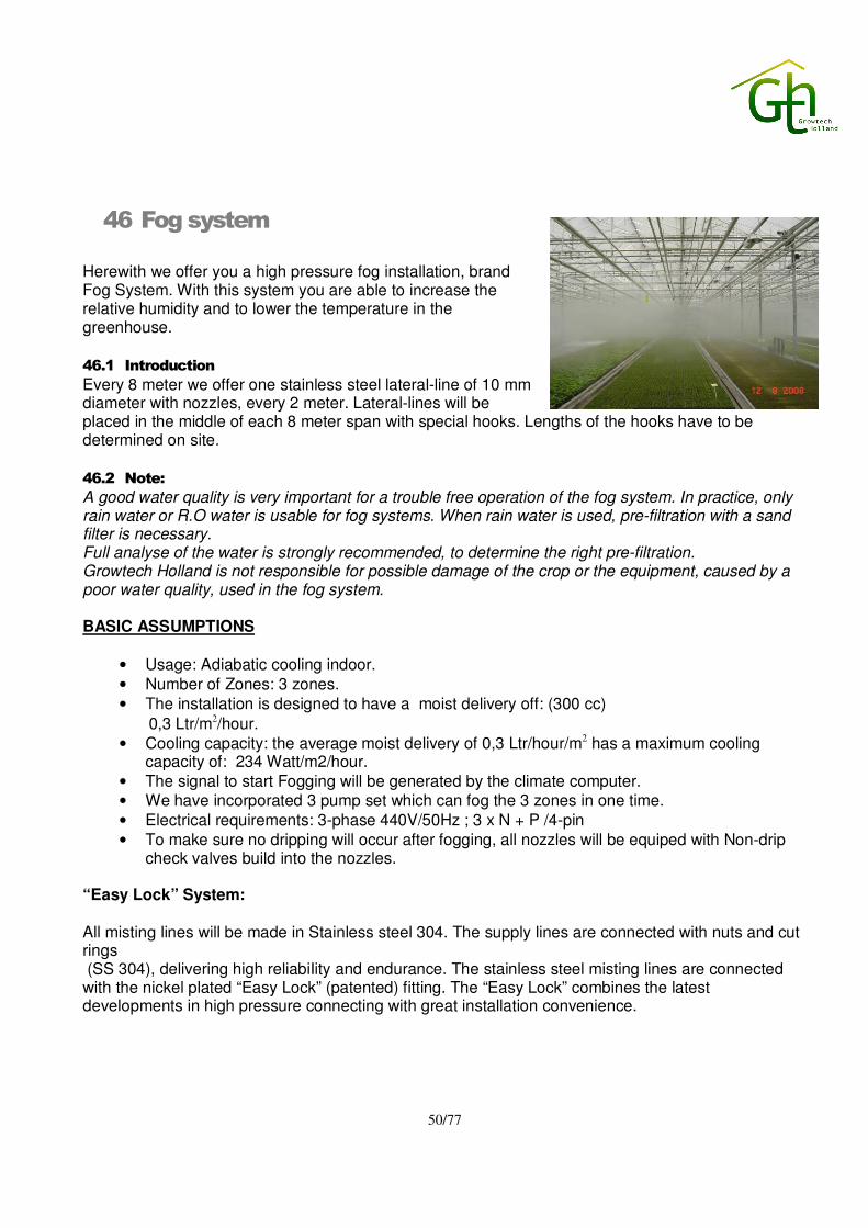
50/77
46 Fog system
Herewith we offer you a high pressure fog installation, brand Fog System. With this system you are able to increase the relative humidity and to lower the temperature in the greenhouse. 46.1 Introduction
Every 8 meter we offer one stainless steel lateral-line of 10 mm diameter with nozzles, every 2 meter. Lateral-lines will be placed in the middle of each 8 meter span with special hooks. Lengths of the hooks have to be determined on site.
46.2 Note:
A good water quality is very important for a trouble free operation of the fog system. In practice, only rain water or R.O water is usable for fog systems. When rain water is used, pre-filtration with a sand filter is necessary. Full analyse of the water is strongly recommended, to determine the right pre-filtration. Growtech Holland is not responsible for possible damage of the crop or the equipment, caused by a poor water quality, used in the fog system. BASIC ASSUMPTIONS
• Usage: Adiabatic cooling indoor. • Number of Zones: 3 zones. • The installation is designed to have a moist delivery off: (300 cc)
0,3 Ltr/m2/hour. • Cooling capacity: the average moist delivery of 0,3 Ltr/hour/m2 has a maximum cooling
capacity of: 234 Watt/m2/hour. • The signal to start Fogging will be generated by the climate computer. • We have incorporated 3 pump set which can fog the 3 zones in one time. • Electrical requirements: 3-phase 440V/50Hz ; 3 x N + P /4-pin • To make sure no dripping will occur after fogging, all nozzles will be equiped with Non-drip
check valves build into the nozzles.
“Easy Lock” System: All misting lines will be made in Stainless steel 304. The supply lines are connected with nuts and cut rings (SS 304), delivering high reliabiIity and endurance. The stainless steel misting lines are connected with the nickel plated “Easy Lock” (patented) fitting. The “Easy Lock” combines the latest developments in high pressure connecting with great installation convenience.

51/77
Placing. From the Pump set placed no further than 50 mtr. away from the zones, a flexible main supply line (1” hose) will be drawn to the compartments. This distribution line will supply the ¾” semi-distribution line and subsequently the ½” semi-line inside the compartments. This ½” semi-line will support the stainless steel nozzle linesNon-drip check valve for a fast stop after fogging and to prevent dripping. 46.3 Materials fog System, fully Stainless steel.
• 1.653 x nozzles (patented) á 4,5 ltr/h, Stainless steel, fogging angle 80º average droplet size
3-6 micron. • 1.653 x non-drip check valves, build into the nozzles to prevent dripping inside the indoor
garden. • flexible 1" high quality main distribution line (NOT hydraulics hose, UV-resistant, no ethylene,
opaque.) Hose fitted with Stainless steel hose inserts and ferrules. • flexible 3/4" high quality supply hose (NOT hydraulics hose, UV-resistant, no ethylene,
opaque.) Hose fitted with Stainless steel hose inserts and ferrules. • flexible 1/2" high quality semi-line (NOT hydraulics hose, UV-resistant, no ethylene, opaque.)
Hose fitted with Stainless steel hose inserts and ferrules. • 10 misting lines @ 74 nozzles • 8 misting lines @ 41 nozzles • 9 misting lines @ 65 nozzles • 1.653 pieces of stainless steel nozzle line @ 2,00 meter • miscellaneous Stainless steel materials (T-pieces, connectors, brackets etc.)
46.4 Pump sets
• 1 Pump Set; (capacity 72 ltr/min). • 1 Pump Set; (capacity 36 ltr/min).
1 Pump Set; (capacity 42 ltr/min). • 3-phase 400V/50Hz ; 3 x N + P /4-pin, (please indicate if
this is correct). Pump: 3 cylinder high pressure triplex pump with ceramic pistons, operating pressure 70 Bar, pump and motor built on a black coated frame
• Small tap on the pump to be able to change oil fast, easy and with clean hands.
• 3 x filter @ 10 micron built on the frame. The filter housing is Opaque ( = anti-algae).
• Pump complete with manometer + pressure regulator + safety valve + by-pass valve • Excess water will flow back in the water supply tank • 3 x pressure switch for low pressure detection built on the pump frame. • High pressure couplings on the pump of Stainless Steel

52/77
46.5 Steering control for 3 zones
Steel plated control panel each with the following controls:
• 1 x switch M/0/A (H= Manual; 0=Off ; A= automatic signal from computer • 24-hour control to start the system running for 1 minute per day in order to help prevent
blockage of the nozzles and make sure water is not standing for a longer period of time to avoid bacterial growth
• 1 x thermal overload pump. • 1 x hour counter for running hours pump on the PLC display. • signals: "power", "failure", "minimum pressure" , "hot water", "low water" "maintenance" & "oil
change" On the PLC display. • contact for connecting external loud alarm. • 1 x power failure alarm contact to your cell phone or computer. • direct steering motor relais pump. • transformer 400V-24/27/30V. • 1 x main switch. • steering cabinet built up on the pump frame + completely wired and equipped with 5 mtr.
cable. This means READY FOR USE. • Electrical requirements: 3-phase 400V/50Hz ; 3 x N + P /4-pin (please indicate if this is
correct).
46.6 Pump unit with water supply pump and pre-filter :
We assume clean water according our specifications is available at this unit. The pump set for the water supply and filtering is based on an installation of the fog systems in all compartments. The pump set assembled with the following components: 1 pc. frame, made of stainless steel; 1 pc. sand filter, coated steel, with a maximum capacity of 60 m³/h, working- pressure 10 bar . The sand filter is provided with automatic backwash valves, consisting of: - 3 pc. electrical valves; - 1 pc. PVC check valve; 1 pc. fine filter 2", coated steel, perforation 130 micron, installed after sand filter; 2 pc. pressure-gauge 0-6 bar, glycerine filled; 1 pc. water supply pump, capacity 10 m3/h at 2.0 bar; 1 pc. Polyester tank content 1.000 ltr incl. lid; 1 pc. fresh water filling valve 50 mm, complete with mechanical level switch; 1 pc. pressure switch for detecting low pressure on suction side HP pump; 1 pc. pressure switch for detecting low pressure on supply side HP pump; 1 pc. white wooden cabinet for assembling of panel and frequency drivers. All necessary fittings and connection materials used in the pump unit are included. All necessary cabling and electrical materials is included.
46.7 Controls:
See program in the computer.

53/77
47 Crop gutter system for cultivating vegetables
General design parameters for steel rolled gutters with suspension Total greenhouse area, 3 departments : 3,0 ha Greenhouse surface : 30.219 m² Greenhouse width : 56,0 meter Bay width : 8,0 meter (2 x 4,0 meter) Number of bays : 7 pieces Greenhouse length : 256,5 meter Number of sections : 57 pieces Section length : 4,5 meter Growing system : 5 gutters per bay Concrete walkway center/gable : Centre Walkway width : 3,0 meter Gutter model : GTH-07-200HD Crop type : Tomatoes Gutter width : 200 mm Gutter height : 105 mm Gable gutter : No Height from bottom trellis to the ground : 4,675 meter Height from gutter platform to the ground : 0,6 meter Size lowest trellis W x H : 50 x 25 mm We only use first class steel, with a 40 mµ polyurethane coating for a 100% protection against rust and dirt. This coating is environmentally friendly and gives the steel an optimum protection against rust. The coating has a smooth surface. The growing system consists of steel rolled drain water collecting gutters, suspension and support assemblies and drain-water collection assemblies. Steel rolled drain-water gutters The scope of supply consists of: Steel rolled gutters with profiled bottom construction, based on the following design parameters: 272 gutters x 68,25 meter = 18.564,0 meter (incl. two extra side gable gutters) The gutters are manufactured inside the greenhouse by our mobile rolling-machine, so the gutters are produced at bay length. We manufacture the gutters from rolls with various lengths, so there are some joints.

54/77
SPECIFICATION OF GUTTERS: Type : GTH – 07 – 200 – HD Shape : According enclosed drawing A reiterate V-shape pattern in the platform of the gutter to control the direction of the drain water flow from the substrate slabs to both channels and optimize the uniformity of the air/water ratio in the slabs Bottom : Depth of water discharge channels 45 mm. Dimensions : Gutter width 200 mm. Gutter height 105 mm. Material : Granite + coating Steel, thickness 0,6 mm, according EN 10142/10143 galvanized on both sides, lacquered outside with
± 7 mµ epoxy primer, inside with 20 mµ epoxy primer with POLYURETHANE coating, 40 mµ thickness smooth.
Color : Outside white, inside off-white.
A is variabel Min 115 / Max 250 mm
42
45
*B = 26
C = A + 52
11105
Note:
- At full load the supported/suspended gutters can have a small deviation in length, with a maximum of 0,75%, because of the inevitable bending of the rolled material. - The thickness of the material can have an inevitable deviation with a maximum of +/-5%, compared with the quoted thickness. - The color can be slightly different from the listed color, due to raw material delivered
from different production batches. - Because of the considerable deformation of the sheet steel during the rolling process,
there may be a visible slight undulation on the surface and the sides of the gutter. - After production there may be spread in length of the gutters of 0,2 % per run, due to inaccuracies of the gutter-machine.

55/77
Gutter suspension assemblies The distance between the suspension assemblies for the quoted gutters is 4,5 meter. For each length of gutter following suspension assemblies, to be installed over the lower greenhouse trellis, will be supplied:
272 gutters x 68,25 meter = 4.080 pieces of suspensions ( 15 suspensions per gutter *) * at the walkway side a junior bracket to stabilize the gutter end Specification of suspension from the lower trellis: Each gutter is suspended by: 15 pieces of trellis-brackets Ø 8 mm, special for installation over the round trellis-pipes 15 pieces of pieces of steel wire Ø 3 mm, L= 3.225 mm 15 pieces of turnbuckle M-8 15 pieces of brackets Ø 8 mm for support of growing/heating pipe,
centre point of growing/heating pipe in centre line of the suspension 14 pieces of triangle brackets Ø 8mm 1 piece of Junior bracket Ø 8mm
Straight suspension Triangle bracket Junior bracket at the walkway side

56/77
Specification of adjustable gutter supporting system at gable end side: At both end gable sides of each greenhouse we supply an adjustable under-gutter support system for all gutter ends. This gutter support system consists of a steel pipe, square 60 x 50 mm ( 3 mm wall thickness), and gable supports, length 600 mm, complete with installation materials.
Integrated in the function of this square steel pipe is the positioning and fixation of the gutter ends, as well as the installation of turn around brackets (option) at gable end side for lowering the plant stems.

57/77
Specification of drain water collecting and discharge system:
Drain-water collection units (end drain units) To collect the drain-water from each individual gutter, one end drain unit per gutter will be supplied. The unit is manufactured of black plastic and has to be installed at the lowest end of the gutter at the gable end sides. Bellow the two outside drain channels with the supplied stainless steel bolts and nuts. In total we supply 272 pieces end drain units.
Each end drain unit has a Ø 40 mm outside diameter water discharge connection. The flexible discharge hose, we will supply, will slide over this connection and has to come down straight into a Ø 50 mm PVC- riser installed at the central greenhouse drain-discharge pipe. This quotation covers the supply of the end drain units with bolts and nuts, the flexible discharge hoses (total of 100,0 meter) and the hose lockers. Installation of these items, as well as the supply and installation of the greenhouse drain water discharge system is customer’s responsibility.

58/77
Our installation services consist of: - The rolling of the steel drain-gutters by our mobile rolling-machine at your construction site.
One GTH-technician operates the rolling-machine. We have taken into account that, during the rolling of the gutters, our technician(s) is (are) assisted by your staff to install the gutters. We will inform you in advance about the exact number of your staff members required to perform the installation.
- Joining of the rolled gutter-end of the last steel roll, to the gutter-end of the new steel roll.
Remarks - Our quoted price is based on the continued installation process at your construction site
without interruptions. If this is not possible you have to inform us in advance. - Growtech Holland will not be liable for eventual damage caused to subsoil piping- and/or
cabling systems if Growtech Holland has not been informed about these systems prior to the installation of the gutter systems.
- A correctly designed slope for the drain-gutters is very important and is the basic principle of an efficient drain water discharge.
For a proper level we advice you to level the soil like from the center walkway into the direction of the end gables at the same slope as the gutters of the greenhouse. Conditions of sales regarding crop gutters: System : the delivery of and services for the crop gutter system do not include include chopping-, digging-, and demolition activities, punching holes or making joints, unless stated otherwise in this technical specification. Delivery : All gutter materials and options. Delays : Growtech Holland shall not be liable for any delay in delivery as a result of inclement weather, fires, strikes, labor disputes, delays in
transportation, shortages of materials, or other causes beyond their control. Warranty: In the function of gutter. 4 years expiry warranty of polyester coated steel. 8 years expiry warranty of polyurethane coated steel.
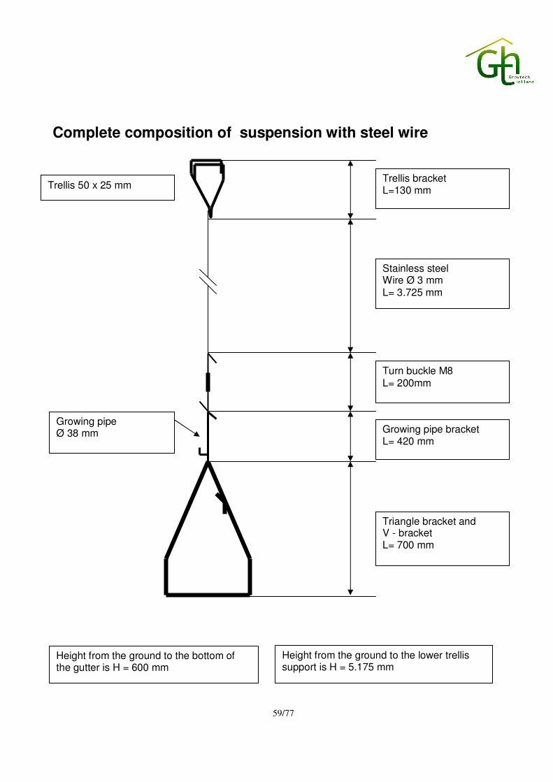
59/77
Complete composition of suspension with steel wire
Trellis bracket L=130 mm
Growing pipe Ø 38 mm
Turn buckle M8 L= 200mm
Stainless steel Wire Ø 3 mm L= 3.725 mm
Growing pipe bracket L= 420 mm
Triangle bracket and V - bracket L= 700 mm
Trellis 50 x 25 mm
Height from the ground to the bottom of the gutter is H = 600 mm
Height from the ground to the lower trellis support is H = 5.175 mm
60/77
48 Substrate with accessories
For growing a tomato crop a complete substrate system is included in our offer. Our substrate system consist of: Rockwool slabs, growing plugs and growing blocks for first planting. We do calculate with 2,5 plants/m² (see paragraph drip irrigation).
49 Tools
For the greenhouse assembly and installation we will deliver the required hand tools. The price mentioned in the price break down is a budget price. You will be invoiced according to the expenses made by Growtech Holland. All invoiced tools will stay at the greenhouse-complex after it has been realized and become the property of the Buyer.
50 Ground cover plastic
21 rolls black/white plastic, 0.07 mm, width 8,40 mtr, on rolls of 200 mtr.

61/77
51 Grading line for medium size round tomatoes
Machine Tomato grader 1-liner with 6 exits
Product MEDIUM SIZE ROUND TOMATOES
Number Description
1 1x tipping belt
- Mod. 500x1500 mm Complete with:
- Only motor, NO inverter
2 1x angled elevator
- Mod. widht 500 mm Complete with:
- Motor with inverter - Hopper between tipping belt and elevator
3 1x sortingtable
- Mod. 500x1500 mm Complete with:
- Motor with inverter
4 1x washer/dryer 650x2350 mm
5 1x conveyor belt
- Mod. 500x1500 mm
Complete with:
- Only motor, NO inverter
6a Rollerstar 1-6+1
- Length app 13750 mm
- Capacity: 3 ton/hour
- Average weight product: 110 gram
- Max. speed: 12 products/sec./lane
- Filling each lane: 65%
Complete with:
- 1x V-groove L=1.300 mm pre-singulator + brushes
- Inverter for V-groove
- Inverter for singulator
- Control box
- Weight
- Chute before loadcells
- Manual lubrication
- 7x rotating receiving brush with ramps

62/77
6b - 7x packing bin
- Standard legs in machine
- Low frame
7 PC
Complete with:
- 17" screen
- Cabinet (only for 17" screen)
- Software
- Laser printer for A4 paper
Camerasystems (MV = Mono Vision)
8a Colour system (C) with camerabox
8b Diameter system (D) with camerabox
8c Colour/diameter system (C/D) with camerabox
9 Integration & control flow
63/77
52 Cold store
Project description:
One Gisopanel cold store with refrigeration plant.
Cold store:
Dimensions: External: 10,000 * 15,000 * 4,000 mm (w*l*h).
Internal: 9,760 * 14,760 * 3,850 mm (w*l*h).
Floor surface: Approx. 144 m2.
Volume: Approx. 555 m3.
Design parameters of the refrigeration equipment:
Product: tomatoes
Storage
temperature: + 12 °C.
Above-mentioned parameters, as well as the customers requirements are applied for the technical
design based on our international standards.
Technical specifications:
Panels: The modular type cold store will be assembled using insulated Gisopanel®
sandwich panels
Specifications:
� Insulation core: expanded flame-extinguishing polystyrene hard foam
quality P20SE.
� Metal sheeting: immersion-galvanised (Sendzimir), profiled steel plates,
thickness 0.6 mm.
64/77
� Thickness insulation core: 120 mm walls, 150 mm ceiling
� Heat transmission coefficient: 0.30 W/m²K walls
0.24 W/m2K ceiling .
� Coating: polyester paint
� Colour: white, RAL 9001
� CFC free
� This EPS panel is tested in accordance with KOMO (The Netherlands)
and UBC 26-3 Room Fire Test Standard For Interior of Foam Plastic Systems
(United States).
Aluminium: The panels (corners, floor and ceiling junctions) will be finished with aluminium
profiles such as angle sections, U-profiles and finishing profiles.
Miscellaneous
materials: Miscellaneous fixing materials such as screws, sealant and vapour-tight tape on
behalf of the assembling of the Gisopanel® sandwich panels.
Vapour barrier: The complete installation will be build to accommodate all thermal movement to
maintain a continuous vapour barrier.
Sliding door: 1 piece manually operated, insulated cold store door, clear opening 2,480 * 2,500
mm (w*h) consisting of an expanded flame-extinguishing polystyrene hard foam
core, quality P20SE. At both sides of the core a steel sheet with a blue, synthetic
Plastisol® coating.
This horizontal sliding door is provided with galvanised locking, toprail and
suspension gear, mounted on high quality waterproof plywood with an epoxy
coating.
Light fixtures: 10 pieces fluorescent light fixtures each with two lamps, selected for low
temperature and high humidity conditions. Specifications:
� Corrosion resistant, splash proof, plastic housing.
� High-impact, acrylic enclosure.
� Positive seal enclosure gasketing.
� Built-in expansion joint between plastic housing and metal liner
prevents cracking of housing during temperature changes.
A on/off switch with indicator will be mounted beside the door.
65/77
Refrigeration equipment:
All refrigeration equipment has been assembled and tested according the latest
international technological developments in order to supply an installation that is
extremely reliable in operation and energy efficient.
All applications are of top quality and pre-fabricated under controlled conditions
inside our factory. This means the assembling activities at the site are reduced.
Refrigeration plant on behalf of the cold store:
Cooling-unit: 1 piece air-cooled cooling-unit, equipped with 1 piece semi hermetic closed
compressor, type Bitzer 4TC-12.2. Because it’s equipped with casing the unit is
suited for outdoor set up.
The cooling unit is, among others, equipped with:
� Oil level indicator.
� Pressure controller and safety.
� Receiver.
� Charging valve.
� Sight glass with moisture indicator.
� Filter-drier.
Cooling capacity: The cooling capacity is based on average use at average maximum ambient
temperatures. The nominal cooling capacity is 30,000 Watt (evaporation
temperature +5°C, condensation temperature +50°C).
Condenser: A remote, air-cooled condenser, make Helpman, type HTC 050.133, equipped
with:
� A core made out of copper pipes with fins of seawater resistant
aluminium alloy.
� Casing and framework are of galvanised steel sheet (Sendzimir).
� Pressure control by cycling one or more fans.

66/77
� Three special splash waterproof- and heat resistant fans. Each fan
has a nominal capacity of 180 Watt, a linear speed of 910 rev/min. The airflow
is 14,600 m3/hr.
The nominal capacity of the condenser is 54,000 Watt based on a condensation
temperature of +40 °C and a temperature difference, between ambient and
condensation temperature, of 15 K.
Evaporator: 2 pieces evaporators, make Helpman, type LEX 24-7 LO, equipped with:
� A core made out of copper Ripple Fin® pipes with aluminum fins.
� Durable aluminum casing, epoxy coated.
� Heavy duty stainless steel electric defrost elements in coil and drip
tray (in case of electrical defrosting).
� Splash guard.
� Expansion and Schrader valve.
� Special splash waterproof fans with aluminum fan blades
provided with a thermal safety device built in the windings.
� Water drain connection.
� Low temperature protection.
� High temperature protection (in case of electrical defrosting).
The temperature difference between air-on and evaporating temperature is 7 K.
This leads to the most suitable humidity inside the cold store.
Heating: 2 pieces electrical elements of 4 kW controlled by the temperature controller and
protected for high temperature.
Refrigerant: R22.
Location: The cooling-unit will be installed outside next to the store.
Condenser should be positioned to achieve the following criteria:
� Adequate space (minimal 1 meter) must be left for free entry to the
coil inlet face.
� No restrictions to the air discharge.
67/77
� No possibility of direct air circulation (short cutting of air).
� No direct sunshine on the surface of the condenser (in tropical
climates).
The condenser will be installed next to the cooling-unit.
Evaporators should be positioned to achieve the following criteria:
� No restrictions to air discharge.
� No possibility of direct air circulation (short cutting of air).
� Free space, between the bottom side of the evaporator and the top of
the product, of at least 200 mm.
Switch box: To control and to secure the electrical circuit of the refrigeration plant a switch
box will be installed on the frame of each cooling unit or immediately next to each
unit. The switch box is, among others, equipped with:
� Main switch.
� Various relays.
� Adjustable thermal overload protectors.
� Overload indicator.
� Contact breakers.
� Under and over voltage monitoring relay.
Cable work: GtH supplies complete cable work for the refrigeration equipment and possible
light fixtures as described in this offer.
Excluded this offer are the feeder cables, power box and main power supply for
each cooling unit.
Piping: All piping is made out of copper and, if required, insulated with vapour tight
insulation.
Remote control
unit: One remote control unit, type GR 2511 installed beside the door equipped with
an electronic temperature sensor and incorporated digital read out, build in a
compact, hard plastic splash waterproof casing. The unit is programmable by
push buttons. Programming options cover; cold store temperature, alarm delays,
automatic/continuous operating evaporator fans, defrost timing etc.

68/77
Supervision: One supervisor will be responsible for the assembling of the equipment at the
site. He will supervise a local team of properly skilled labour and will do the most
complicated parts of the job. The costs of local labour are excluded from this
offer.
53 Emergency power unit – generator set
To provide in back up power supply, in case of a power failure, we offer you a new, sound proof diesel generator set. Specifications: - Cummings - Voltage 3x400 Volt, 50 Hz; - Continue power supply 100 kVA; - Standby power supply 110 kVA, Including: - control panel, Volts-meter en Amps-meter; - carter preheating; - Stator anti-condensation heating; - Exhaust through closets wall or gable. This generator set is to be supplied with an automatic start/stop system, in case of power failure. The generator set is to be delivered with automatic ‘main-off-generator’ transfer switch. Note: - The continue power supply (100 kVA) is based on emergency power and therefore 80% of the
main power supply. Forced shut down of certain equipment to be discussed. - Generator capacity is not based on emergency supply to growlight system. - The generator set will be connected by means of generator cable. The size of this cable is based
on a maximum length of 10 mtr. (distance between main breaker panel and generator set)

69/77
54 Internal transport
12 x Electric pipe rail trolley Bogaerts BBR-020-HH 425/51(BR436)
Double hydraulic scissors Mechanic lifting system, for side moving Heart to heart size (mm): 425 Pipe diameter (mm): 51 Size plateau (cm): 190 long Min. plateau height (cm): 56 Max. plateau height (cm): 300 Dimension chassis l x b (cm): 190 x 54 Total dimensions incl. draw-hook (cm): 195 x 54 All pipe-rail trolleys have standard: -24V 0,37kW driver engine -24V 2,20kW hydraulic engine -electronic Reghel-quad regulator -closed housing to prevent vegetation to get in the wheel -powder-coated frame -user friendly operating system -heavy safety break switch -container draw-hook -2 x full traction battery 115Ah
6 x Mori battery charger (AL30) - Complete whit drip load function - Possible to charge almost empty battery’s - Find potential differences and solve it - Electronic protection against current overload 30 x Transport cart with flange rol BP 187x47, 4 turn around wheels (BP60) 187cm long and 47,4cm breed Including: Flange roll
Middle wheel 4 x turning wheel
55 High wire hooks
To be able to let tomato plants grow towards steel crop wire you need special wire to guide tomato plant. For this purpose and to be able to work a proper height we do include in our quotation high wire hooks. For 3 hectares of growing area we deliver 79.000 high wire hooks with with wire. During cultivation you will also work with 1 branch of every third plant. For the branches we have included 26.000 high wire hooks with twine in 1 colour.

70/77
56 Spray cart “Georgia”
The popular spray cart “Georgia” is equipped with all modern conveniences. The spray cart “Georgia” is constructed in such manner that all controls are positioned on one side of the cart as a result of which unnecessary walking around the cart will be avoided. Even the filling hole is positioned, as much as possible, at the side of the tank. The tank can easily be reached for filling purposes, as the wheel boxes buried in the tank makes the whole cart low based. To put it briefly, this extremely user friendly spray cart which will keep you going for years. Characteristics: • Polyethylene liquid tank, 1.000-litre content, highly smooth finishing on the inside as well as on the outside. • Strainer box in the filling hole. • Tab cover with ventilation. • Clean water tank, over 16-litre content with drain tap manufactured in black polyethylene, completely buried in the large tank. • Because the suction hose is assembled on the bottom, in a deepening, the pump will fully empty the tank as a result of which the residual liquid will be limited to an absolute minimum. • All horizontal surfaces within the tank are at least 7° slanting. • A lockable suction filter which enable the filter being cleaned with a full tank. • A filling pipe with quick connector and a non-return valve are assembled in the tank. • A water gauge with a scale marking per 50 litres and a drain tap are assembled. • A pressure relief tap is assembled on the pump. • There is an injection nozzle in the tank to mix the spray liquids in an optimum manner. • 4 Wheel 6 ply with brake on the front wheels. • Various reels, spray guns and options can be assembled. • Powder coated frame. Specification of complete spray cart with Fanmast: * 1 pc. Spraycart ‘Georgia’ with 1.000 ltr. polyethylene tank * 1 pc. Electric reel 400 Volt, speed control + mounted on the machine * 100 mtr. ‘M-plus hose’ – rubber 3/8“ * 2 pc. Coupling 3/8”, conic * 1 pc. 3-nozzle spray lance * 3 pcs. Nozzles with connection materials * 1 pc. Spray mast 10 nozzles * 1 pc. Frame tube rail for spray mast
71/77
57 Construction supervision
1) GtH will send supervisors to control all installations works. This supervision is offered to you for the period of 30 person-weeks of supervision services, based on 1 person/week equal to 6 working days by 10 working hours each day. Travelling days are considered as working days. During this period, specialists of the different trades (building, glazing, screening, heating, electrical systems and irrigation) will instruct your people how to construct a greenhouse. It is the client’s responsibility to supply enough workers and machinery to finish the project in time. 2) International traveling costs are included. 3) Client is responsible for and has, for his account, to take care of:
• Accommodation in hotel according to Western standards. • Each supervisor in a single room. • Proper sanitary facilities, including constant supply of hot water and potable water. • Food & drinks supply and services on site during working hours. • Availability of international communications facilities (telephone/fax). • Local transport
4) The Client will provide (for his account):
• At least two qualified interpreters to English. • An authorized site manager available on site at all times. • Proper storing facilities with security on site.
58 Assembly and construction works
Assembly-construction works (ACW) within “perimeter/gables of the GH” and working out project documentation within borders/fences for a greenhouse-complex with an area of approx. 3 hectares, to be realized in Armenia.
1. Working out project documentation within “borders/fences of the greenhouse-complex”, excluding outside networks (infrastructure)
2. The list of ACW:
� Assembling of the foundation dollies � Assembling of the steel constructions, ventilation mechanism � Assembling of the technological network of mains below ground level (“0”-level) � Assembling of the heating installation � Assembling of the technological equipment of the boiler house � Glazing � Assembling of the screening installation (horizontal and vertical) � Assembling of the network of mains above ground (drip irrigation, drainage, condense
discharge, overhead irrigation, rainwater collection, high pressure cooling)

72/77
� Assembling of the electrical system � Assembling of the recirculation fans � Assembling of the technological equipment (irrigation room, water storage tanks,
disinfection system) � Assembling of the computer system � Assembling of growlight system propagation greenhouse � Assembling of cold stores � Assembling of steel crop gutter system
All machinery and building equipment necessary for ACW to be provided for account of the Client. The price for ACW includes traveling expenses and expenses for food for builders. The price for ACW is excluding the expenses for lodging for the builders, these expenses are for account of the client. The price of ACW will be verified after working out of the project documentation. Developping works are not included in our prices.
Works related to vertical planning/levelling of the soil, digging in and back filling of trenches, filling in of concrete in perimeter foundation, concrete floors and paths onto responsibility and account of the Client. Works related to mounting dripper sets in pre-punches holes, installation of the soilless substrate slabs and high wire hooks to be done by the Client.
59 Freight
For the transportation of all materials for a turnkey greenhouse-complex, which includes the greenhouse construction, all greenhouse installations and equipment, all other greenhouse materials we do estimate that 58 pcs. tautliner trucks (or 40 feet containers are required) for all the materials and equipment plus 2 special transports for shipping the boilers. Please note that glass panes and heating tubes 51 mm. are to be supplied by and for account of Client.
60 Materials loading and packing
Materials will be loaded in trucks or containers Packing as commonly known in shipping glasshouse materials and according to the general conditions known for sea or truck freight.

73/77
61 Obligations of the Client
- Developing works to meet local standards - Approvals and expertise of the project to meet local standards and norms - All construction activities - Have an English speaking supervisor on site - Concrete foundations, GtH will prepare foundation drawings, and a supervisor - Concrete floors and walkways - Building permits and visas - Have people available to work on Saturday’s and during evenings and holidays if necessary - Permission to work during evenings and holidays - Preparation of the building site (free of obstacles till at least 1 m depth) - Temporary electrical power on the building site. - Complete welding crew for welding in the greenhouses - All Interiors in the service building like offices and toilets - Clean running water on the site - Inland transport - Proper unloading surface - Unloading trucks / containers, on the building site. - Dry storage for sensitive materials. - Safe facilities to store high value materials - Covering the glass after arrival - Provide forklifts during construction (4wd) - Provide tractors during construction - Provide scissor lifts during construction (4wd) - Provide fuel for machines mentioned above, and for our the glazing machines - Local transportation for builders. This means transport from the airport to the site, and
transport from hotel to the site. - Insurance of materials, for inland transport and on site. - Canteen, site office and toilet facilities - Disposal of garbage. - Telephone connection with fax line free of charge. - Provides the site duly levelled and free from any physical obstructions to enable GtH the
commencement of concrete works. - Provides electricity 220/380V, 50 Hz, sufficient quantity of water for construction purposes and
road access to the construction site. For use of such during construction and start-up. - Digging of trenches (if required) - Sand for backfilling (if required) - Backfilling of the trenches - Painting of the heating pipes. - The necessary hewing-, digging- break-, and brickwork, and carpentry. - Fuel for testing - Any required local engineering - Cost of documentation, local fees - Import duties - Customs duties, clearance, inspection fees, and all types of taxes are responsibility of
purchaser.

74/77
- All local taxes - Gas lines and tank. - Co2 installation - Heat storage tank - Oil tank - Soil tests with foundation advice. - Any item not specifically mention in this offer.
62 Delivery
Delivery period: to be agreed upon. Free Carrier Gemeente Westland, The Netherlands, according Incoterms 2010-edition. Not included: handling charges for clearing the goods.
63 General conditions
63.1 Payment terms
To be discussed. Payment shall be made in the original currency as quoted We will use our best endeavours to implement any contract resulting from this offer within the time fixed by such contract or any extension thereof and we cannot be held responsible for delays in delivery or erection due to breakdown of machinery, labour disputes, war, riots, civil commotions, shortage of labour, delay in delivery from overseas shippers or manufacturers, transportation, acci-dents, regulations or orders from any government, or any other cause whatsoever. The client shall not be released from his contract by reason of any such delay. GtH shall supply all goods and equipment relating to their greenhouses in brand new condition and good quality as per the specification in this offer. Prices are exclusive custom clearing and inspection of the materials, custom and import duties. Prices are exclusive of VAT, all other duties payable of the time of transportation, local taxes, sales taxes, etc. Prices are exclusive labour. All given prices are based on the actual wages, prices, freight costs, exchange rates and your data. There fore we reserve the right to review our prices in case of any changes of one of the aforementioned factors.

75/77
Construction All Risk Insurance is excluded from this offer. In our offer we did include 30 weeks of supervision. Travel expenses, board and lodging up to Western European standards and adequate local transport will be for the responsibility and account of Client. The maximum duration of a trip is 10 weeks. VAT identity code of GtH is NL812669794B01. This offer is valid until 60 days after the date of this offer. The general conditions of Growtech Holland den Heijer b.v. applies to all of our services and supplies. Theses conditions are filed with the District Court of The Hague on January 26th 2004 under number 05/2004. We will send you a copy of the general conditions on request.
64 Additional terms
Our technical specification can be subject to modification, which will only be carried into effect to improve the quality of our project. GtH will not be responsible for damage incurred to equipment installed by a third party not belonging to works carried out by GtH. The foundation will be delivered in a good condition, however GtH cannot be held responsible for the bearing capacity of the ground of the project site. GtH shall guarantee the materials of the project after commissioning for one year only when the erection and installation have been executed under supervision of GtH. This will apply to any defect in the workmanship of the supplied materials, but not in case of any misuse of these materials. Glass and electrical motors are excluded from any guarantee, except that GtH will assign over to the Client the manufacturers guarantee. GtH shall be under no liability in respect of damages or accidents arising from repairs or maintenance carried out on the roof by the Client. GtH is only liable for damage suffered by the Client which is the immediate and direct result of a shortcoming attributable to GtH with the understanding that liability is under all circumstances limited to the amount of the purchase/contracting agreement. Assertion of a claim on indirect damages is excluded.
- - - - - - - - - - - - - - - -

76/77
65 Price breakdown 3 hectares greenhouse for tomatoes
* Greenhouse system & service-building excl. glass panes
€ 875.500,-
* Horizontal screening installation € 124.015,- * Vertical screening installation € 43.890,- * Heating system with heat storage installation, excl. heating tube Ø 51 mm.
€ 953.870,-
* Electrical installation € 84.240,- * Recirculation fans € 19.440,- * Horticultural computer system € 70.200,- * Growlight system – propagation area € 131.250,- * Drip irrigation € 85.320,- * Drainwater collection and re-using € 16.740,- * UV-disinfection system € 55.645,- * High pressure fog system € 181.735,- * Water storage tanks € 18.575,- * Rainwater collection system € 28.080,- * Condenswater collection € 7.560,- * CO2 dosing system (from boiler) € 22.140,- * Overhead irrigation € 7.020,- * Steel hanging gutter system € 203.970,- * Substrate & accessories € 46.340,- * Tools € 21.600,- * Ground cover plastic € 5.670,-

77/77
* Internal transport € 70.250,- * Cold store € 66.420,- * Emergency power unit (generator) € 25.595,- * Empas spray cart ‘Georgia’ 1.000 ltr. € 10.040,- * Tomato grader € 199.800,- * High wire hooks € 14.175,- * Supervision (30 person-weeks) € 165.000,- * Assembly and Construction Works € 813.370,-
Total project, excl. freight, VAT and (import) duties:
€ 4.367.450,-