grouting at tannur dam in ejge - hashemite university · using grouting intensity number (gin)...
TRANSCRIPT

1
Improvement of Dam Foundation Using Grouting Intensity Number
(GIN) Technique at Tannur Dam Site, South Jordan
Mustafa Al Kuisi University of Jordan, Department of Geology, Amman, Jordan
E-mail: [email protected],
Ali El Naqa Hashemite University, Faculty of Natural Resources and Environment Department of Water Management and Environment, Zarqa, Jordan
E-mail: [email protected]
Fathi Shaqour University of Jordan, Department of Geology, Jordan
E-mail :[email protected]
ABSTRACT
The Grouting Intensity Number (GIN) method was used for the first time in the foundation treatment of the Tannur Dam site, the first of its kind of foundation treatment in Jordan. 3m wide curtain was established under the dam body at both the left and right abutments, while a very extensive program of curtain grouting has been carried out at the central section. All the grouting was carried out by the GIN method, using a GIN number of 1500 was applied with a maximum allowable grout pressure of 30 bars. The grouting program in the left, right and central section has resulted in average Lugeon values of 3 to a maximum of 6. The grouting program has also been very extensive to ensure that any potential voids / fissures caused by the geological fold / stress relief have been sealed.

2
INTRODUCTION
Jordan is characterized by semi arid climate, which suffers from water shortage and limited water supply. In the last few decades the water demand increased rapidly due to the high rate of population growth and population influxes i.e. returnees from neighboring countries together with the higher needs for the industry in the country. In order to meet such water needs, the Ministry of Water & Irrigation has recently extended a number of projects at sites in the southern desert area, that are suitable for the construction of storage dams to be used primarily for domestic, recharge of groundwater, and irrigation purposes.
Tannur Dam is one of these projects and the first of three roller compacted concrete (RCC) dams built in Jordan as part of the Southern Ghors water supply and irrigation scheme in the Jordan valley. It is located in the Wadi Al Hasa, about 30 km east of the Dead Sea and 50 km south of the town of Karak (Fig.1). The dam area was investigated by local and international consulting engineering firms (McDonald and Partners, 1969; Howard Humphreys and Partners, 1995 and Mott MacDonald, 1999). Construction of the dam was commenced in January 2000 and completed in 2001.
The narrow site and reasonably good bedrock at shallow depth led to the choice of a concrete gravity dam, with the availability of naturally occurring pozzolan making RCC the most suitable form. The dam lies in a narrow V-shaped valley in a highly seismic area, the steep valley sides rising at 30 degrees to a 60 m height above the bed of the wadi, which is a stream that remains dry except in the rainy season, when it feeds the southern Dead Sea.
Packer permeability tests were carried out in vertical as well as inclined boreholes by Howard Humphreys & Partners (1994) and Mott McDonald (2001). The packer tests were performed at 3 vertical boreholes penetrating the dam foundation and 4 inclined boreholes with inclination angles ranging between 15° to 30°. The main objective of these tests was to determine the permeability of the rock masses of the dam foundation and its abutments. The results of these tests indicated that the permeability of Fuheis-Hummar-Shueib (FHS) Formations and the Wadi El Sir Formation (A7), which form the bedrock of the dam site, ranges between 10-300 Lugeons. In the vertical boreholes, 10% of the permeability values are above 300 lugeons while in the inclined boreholes 33% of the permeability values are above 300 Lugeons. The high Lugeon values indicated highly jointed rock masses, which need to be grouted especially in A7 formation. The Lugeon values in the FHS formation range from 0.5 to 20, as these materials are closely jointed, therefore they will need less grouting (El-Naqa and Kuisi, 2002).
GEOLOGICAL FRAMEWORK
Deposits that belong to the Upper Cretaceous age dominate the dam site. Upper Cretaceous deposits in Jordan are formed of limestones, marls, dolomitic

3
limestones with clay horizons. They range in thickness from a few hundred meters to about 1000 meters. These deposits have been classified into two main series a) Ajlun b) Balqa where each was subdivided into formations (A1 to A7 for Ajlun and B1 to B5 for Balqa) (Quennel, 1955; Masri, 1968). The formations are shown in Figure 2, which in some locations are mixed and hardly differentiated, especially in south Jordan, where the study area is located. The oldest outcrops in the dam site are undifferentiated deposits that belong to Fuheis (A3), Hummar (A4) and Shueib (A5,6) Formations and therefore it is know as Fuheis – Hummar – Shueib (FHS) Formation (Abed, 2000).
Figure 1. Location of Tannur dam in Jordan
This Formation outcrops at the left abutment and the reservoir area as shown in the generalized geological map of the dam sit (Figure 2). It consists of thin to moderately thick bedded (1 to 50 cm thick) limestone, marlstone, marl and clayey marl, with gypsum bands. The limestone is moderately hard to moderately weak. These strata were encountered in all exploratory boreholes along the dam

4
axis and in the adits dug on the dam axis. The sequence contains bands of marl and fossiliferous limestone up to 0.5 meters thick. These deposits are overlain by what is known as Wadi Es Sir Limestone (A7) that consists of massive, thickly and thinly bedded limestone with nodules of chert interbedded with marly limestone and dolomitic limestone. Figure 3, presents a geological cross section across the dam axis, which illustrates the rock sequence of the dam site.
Figure 2. Geologic formations in the vicinity of the dam
The foundation area is entirely composed of the (FHS) formation, comprising alternation of marly limestone, limestone and grey marls, and red and green marls with gypsum. Borehole logs for the central section based on the holes placed as part of the construction site investigations and grouting exploratory holes. The dip at the site is 18 – 20o in an approximately northerly direction,

5
resulting in an apparent dip of about 16o in an upstream – downstream direction and 5o towards the right side in a direction parallel to the dam axis. However the foundation excavations at the central part of the dam wall indicated a geological fold feature. The colluvial deposits are frequently encountered throughout the dam area, primarily on hillsides and hilltops outside of wadis. The colluvium comprises a heterogeneous mixture of angular to surrounded particles from boulders to sand size particles with some silt and silty clay and marl. Mostly thick unstable landslide materials and/or colluvium cover the dam site and the reservoir area. The bed of Wadi Al-Hasa downstream of the siq in the Nau'r limestones comprises wadi gravel up to 70 m wide and a maximum thickness of 15 m on the dam axis. The wadi gravel comprises cobbles and boulders with a silty sand matrix. The major structural feature of the area is the Wadi Al Hasa fault, which strikes WNW in the region of the dam and lies 500 m to the northeast of the dam site. Wadi Al Hasa fault strikes generally E-W form the Dead Sea Fault, which is located about 23 km west of the dam site. To the east it dies away in a series of minor faults to merge with the Karak-Faiha fault (Bender, 1974).
THEORETICAL BACKGROUND Grouting is a geotechnical process, which involves injection of cement or chemical grout for the purpose of filling cracks or voids in the rock mass or soil. A rock mass is normally jointed by a number of joint systems, that can carry water. It is these joint systems that need to be filled out to reach a sealing of the rock mass. The most common grout in rock foundations is cement grout, which is injected into the rock mass joint system by a pump at high pressure. Chemical grout could also be used in certain cases (Dalmalm, 2001). Grouting can be carried out, either before the rock is excavated known as pre-grouting, or after excavating part of the foundation. The success of grouting process depends on understanding the rock mass conditions, especially its hydraulic properties and on the grout characteristics and its behavior. Earlier studies on grouting describe some basic principles Cambefort (1964), Wallner (1976), Cambefort (1977), Lombardi (1985). The studied relation between grout-take and hydraulic properties of the rock mass was considered weak (Ewert, 1992). By using the GIN-principle for grouting performance the rock mass properties are studied during grouting hence giving a possible way of controlling the grouting process (Lombardi & Deere, 1993). The grout flow has as well been described by numerical calculations (Wallner,1976).
GROUTING INTENSITY NUMBER (GIN) METHOD
The Grouting Intensity Number (GIN) involves the energy expended, which is grouting pressure P, and the grout volume injected V. The product PV is called the Grouting Intensity Number or GIN. The volume may be unitized to the length of the grouting intervals as liters/m (or interchangeably as weight of cement injected in kg/m, since for moderately thick mixes the numerical values are
6
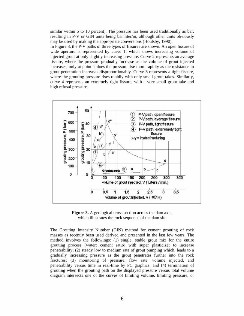
similar within 5 to 10 percent). The pressure has been used traditionally as bar, resulting in P-V or GIN units being bar liter/m, although other units obviously may be used by making the appropriate conversions (Houlsby, 1990). In Figure 3, the P-V paths of three types of fissures are shown. An open fissure of wide aperture is represented by curve 1, which shows increasing volume of injected grout at only slightly increasing pressure. Curve 2 represents an average fissure, where the pressure gradually increase as the volume of grout injected increases, only at point a' does the pressure rise more rapidly as the resistance to grout penetration increases disproportionably. Curve 3 represents a tight fissure, where the grouting pressure rises rapidly with only small grout takes. Similarly, curve 4 represents an extremely tight fissure, with a very small grout take and high refusal pressure.
Figure 3. A geological cross section across the dam axis,
which illustrates the rock sequence of the dam site
The Grouting Intensity Number (GIN) method for cement grouting of rock masses as recently been used derived and presented in the last few years. The method involves the followings: (1) single, stable grout mix for the entire grouting process (water: cement ratio) with super plasticizer to increase penetrability; (2) steady low to medium rate of grout pumping which, leads to a gradually increasing pressure as the grout penetrates further into the rock fractures; (3) monitoring of pressure, flow rate, volume injected, and penetrability versus time in real-time by PC graphics; and (4) termination of grouting when the grouting path on the displayed pressure versus total volume diagram intersects one of the curves of limiting volume, limiting pressure, or

7
limiting grouting intensity, as given by the selected GIN hyperbolic curve (Figures 4 and 5) (Houlsby, 1992, Bell, 1992).
Figure 4. Selected GIN hyperbolic curve and the grouting path
Figure 5.
The GIN principle requires fixing a grouting intensity level (for instance, a high intensity GIN of 2000 bar l/m); this value is used both for the easily grouted fissures, with large volume absorptions at low pressure, and for finer fissures, with low takes but with considerably higher pressures (Houlsby, 1990). A constant GIN value, when plotted on a pressure versus volume graph, yields a hyperbolic curve. The higher the grouting intensity or GIN value, the greater the distance of the curve from the origin. The GIN curve thus completes the missing ingredient for joining the other two limits: the limiting volume line and the

8
limiting pressure line. The combination of the three gives the composite limiting envelope for grouting (Houlsby, 1990 and Lombardi and Deere, 1993). The dam designer and his geotechnical and grouting staff must select The GIN value for the projected grout curtain based on site investigation and foundation characteristics. Lombardi and Deere (1993) recommend a moderate GIN value of 1500 bar l/m as an initial value considering the value of future water losses, and uplift pressures after impounding. The upper pressure limit is less in the abutments based on the depth of water column.
DESIGN OF GROUTING WORK To investigate the ground before grouting works, coring method with double-tube-core barrels using water flush, were used in drilling the preliminary (exploratory) holes with continuous permeability testing. The core samples from each borehole were extruded from the barrel in the horizontal position and placed in core boxes. The core boxes were labeled with borehole number, box number and depth. For the curtain grouting under the left and right abutments, 76mm diameter boreholes were drilled using air flushing. At the central section of the dam and due to the presence of marls and sandy layers, which were continuously collapsing during drilling, a 114mm diameter OD top-percussion cased drilling method was used. Due to the presence of fill material at the top 7m under the contact consolidation line, located at the upstream hell of the central section, the Odex method (140mm diameter) of drilling was used. Table 1 illustrates the different types and conditions of the drilled holes for grouting purposes.
Table 1. Types and characteristics of the boreholes drilled for grouting works
Hole Designation Hole Spacing Hole Type Hole Diameter Drilling Method Permeability Testing
Preliminary 24m Investigation 100mm Coring Every 5m
Primary 8m Curtain Grout 76mm Percussion /OD None
Secondary 4m Curtain Grout 76mm Percussion /OD None
Tertiary 2m Curtain Grout 76mm Percussion /OD None
Quaternary 1m Curtain Grout 76mm Percussion /OD None
Contact 0.5-1m Consolidation 140mm Odex None
Control Random Checking 76mm Percussion Every 5m
Drilling in the exploratory holes reached down to 50m below the dam foundation to help designing the curtain depth. The holes for the curtain grouting were drilled down to about 35m under the left and right abutments and down to 65m

9
under the central section ground level or 55m under the dam foundation level. Drilling for the contact consolidation grouting was to 20m below ground level or 10m below the dam foundation level at the central section.
Figure 6.
The grouting program at the left abutment, central section and right abutment have comprised a two line grout curtain, with 3 m distance in between from the upstream comprising primary at 8 m, secondary at 4 m and tertiary at 2 m spacing respectively. In the central section, quaternary holes were added. These grout lines are shown in Figures 6 and 7. All the grouting was carried out by the GIN method based on a GIN number of 1500. Maximum allowable grout pressures ranged from 10 to 30 bars depending on the depth. Grouting was generally carried out in ascending stages, except for the final line of quaternary holes.

10
Figure 7.
In the central section, due to the presence of gypsum bands and marlstones/clayey marls an extensive grouting program was carried out to ensure that all potential fissures or voids were sealed. The depth of grout curtain into the marlstones/clayey marls is 45 m on the downstream line and 55 m on the upstream line. In addition it was decided that when the GIN plot of flow against pressure for each 5 m stage reached the GIN curve (GIN number – 1500), the grouting should be continued following down the GIN curve. The Tube á Manchette (TaM) was used due to the presence of weak sandstone layer in the foundation.
Grout Mix Type The grout mix of the curtain grouting had been selected for this dam site after several tests performed on materials available locally. The chosen type of mix consisted of 1:1 Water: Cement ratio with 2% Bentonite (By weight in relation to the cement) and 2 liters of Super plasticizer (Additive) per 100 kg of cement. The cement is the normal Ordinary Portland Cement type (1) according to BS 12/91. For backfilling, which was used when high grout takes were encountered, the grout mix consisted of 1: 2.5 water to cement ratio. This thick grout was used rarely in some holes. Table 2 presents the different grout mix types used in grouting under the dam.
Table 2. Grout mix type injected under the Dam

11
GROUT MIX PER CUBIC METER
GROUT NAME Water
(Liter) Cement
(kg) Bentonite
(kg) Admixture
(Liter)
GIN 750 750 18 20
Backfilling 560 1400 - -
Sleeve 910 250 25 -
Grouting Programs for Left and Right Abutments and Central Section
Downstream Line Grouting results are shown in Figure 8. Grout takes in the downstream line generally ranged between 40 and 300 kg of cement per meter with some results of less than 40kg. There was only one 5m stage in the total program for this particular line, where the grout take was in excess of 400 kg/m. This was at depth (El.300) on the right abutment. The downstream line was placed, vertically in view of the problems of collapse. There was however no significant sequence of reduction in grout takes between primaries, secondaries and tertiaries.
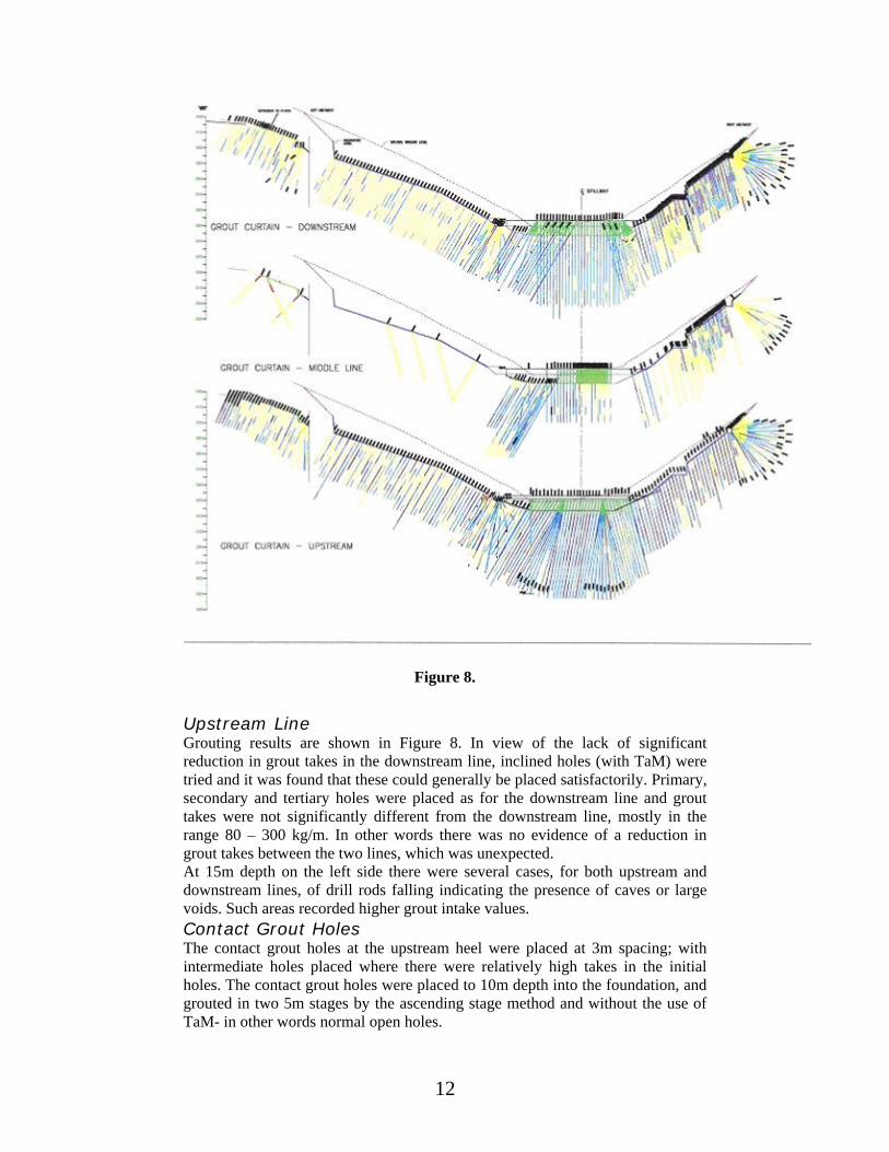
12
Figure 8.
Upstream Line Grouting results are shown in Figure 8. In view of the lack of significant reduction in grout takes in the downstream line, inclined holes (with TaM) were tried and it was found that these could generally be placed satisfactorily. Primary, secondary and tertiary holes were placed as for the downstream line and grout takes were not significantly different from the downstream line, mostly in the range 80 – 300 kg/m. In other words there was no evidence of a reduction in grout takes between the two lines, which was unexpected. At 15m depth on the left side there were several cases, for both upstream and downstream lines, of drill rods falling indicating the presence of caves or large voids. Such areas recorded higher grout intake values. Contact Grout Holes The contact grout holes at the upstream heel were placed at 3m spacing; with intermediate holes placed where there were relatively high takes in the initial holes. The contact grout holes were placed to 10m depth into the foundation, and grouted in two 5m stages by the ascending stage method and without the use of TaM- in other words normal open holes.

13
These holes had two purposes, to help consolidate the foundation at the heel where stresses could be high, and to also lengthening the seepage path. There was a wide range of grout takes, including results above 300 kg/m. The top stage and some of the other higher takes may have been due to leakage to the surface directly upstream, with only a short path to the edge of the dam. It would not have been possible to see these leaks due to the backfill over the area. Table 3 presents the total number of holes and meters drilled, as well as, the grouted quantities at the different locations under the dam foundation. In summary the total number of holes drilled for grouting purposes under the dam is 736 No. with a total of about 20000 linear meters and the total quantity of grout injected is about 2750.32 cubic meters.
Table 3. Descriptive statistics of the drilled boreholes and their grouting intakes
UPSTREAM LINE MIDDLE LINE DOWNSTREAM LINE
CURTAIN LOCATION Number
of Holes
Drilled Meters
Grout Take M3
Number of Holes
DrilledMeters
Grout Take M3
Number of Holes
Drilled Meters
Grout Take M3
Left Abutment 84 2339 302.42 12 368.50 32.75 81 2318 122.66
Central Section 137 6015 776.53 20 1022 52.38 101 577 437.19
Right Abutment 71 1879 419.05 57 1490.5 114.92 93 2415 276.82
CONTACT CONSOLIDATION PRIMARY HOLES SECONDARY NOLES TERTIARY HOLES
Central Section 31 581.1 68.3 30 562.50 87.1 19 380.2 60.2
ASSESSMENT OF GROUTING AND WATER TESTING
A very extensive program of grouting was conducted. The grouting results have shown no areas of very large takes, but correspondingly the grout takes have remained higher than expected after each stage of primary, secondary and tertiary holes. In part, however, the grout takes are higher due to extending the grouting at each stage beyond the period of normal practice after the GIN curve is reached. Normally when there is no significant reduction in grout take from primaries through to tertiaries, the indications are that either closer spaced holes are required and / or the GIN number need to be increased. In this context quaternary holes at 1m spacing were eventually placed. However the GIN number of 1500 was not increased, as this was already considered to be the appropriate number for the bedrock conditions and the height of dam.

14
It should however be noted that relatively high maximum pressures were adopted, with the purpose of opening up incipient joints to enable grout travel. Except in very strong rock, grouting pressures will be expected to open up joints and this is normal to allow grout travel into narrow fissures without the further stage of hydrofracturing of the rock. Inspection of the grout take / pressure plots and then the water pressure tests show no or little evidence of hydrofracture. For the majority of grouting stages, the final maximum pressure occurred when the GIN curve was reached, before the specified maximum allowable pressure. It is considered that the difficulty of achieving lower final lugeon values less than 3 – 5 has been due to the quality of the bedrock. It is much easier to grout dense albeit fractured rock, as for example on the abutments, where permeabilities of 1 lugeon or less were achieved. The problem is considered to be due to the difficulties of grouting thin fissures. A normal minimum fissure width for grouting is three times the maximum grain size of the cement. For normal cement such as used for the grouting at Tannur, this would indicate a minimum fissure width of 0.2mm. A smaller width would require use of special finer cement, which is not available in Jordan. This indicates the difficulty of reducing the permeability below 5 lugeons by conventional cement grouting when narrow fissures are present. It can be concluded therefore that the final permeability of up to 5 lugeons with an average of 3 lugeons is logical in the context of the bedrock type and quality.
CONCLUSION The grouting programme in the central section has resulted in average lugeon values of 3 and a maximum of 6. The grouting programme has also been very extensive to ensure that any potential voids / fissures caused by the geological fold / stress relief have been sealed. A permeability of 3–5 lugeons is recognized as being quite acceptable for concrete gravity dams where there is no risk of deterioration of the foundations due to piping or dissolution. In the case of the former, all the drain holes from the gallery have filter linings principally to protect the clayey marls interbedded with the dolomitic limestone-marly limestone. In the case of dissolution, this is not a risk in view of the low permeability of the rock, but as a safeguard there should be a close monitoring of the seepage and downstream wadi flows for any indication of higher calcium or sulphates content. It is also proposed that this should be backed up by the inclusion of two deep inclinometers in the dam foundation to monitor any evidence of movement. In the case of seepage flows through the dam foundation, these should be less than 20 l/s assuming the closure permeability of 3–5 lugeons has been achieved throughout the curtain at the Central Section. A marginally lower permeability may be achievable by continuing the grouting programme, but this is constrained by the quality of the rock and is not considered justifiable. However it has been recommended that a silt blanket is placed directly upstream of the dam to link with the natural blanket, which will help to reduce the seepage. If the present seepage of 1.7 l/s is entirely due to seepage under the dam, at the present head differential of 8m, the flow from the central section when the reservoir is at full supply level will increase in proportion to the head difference

15
to around 12 l/s and this flow would increase further due to the shorter drainage path when the drain holes from the drainage gallery are placed.
REFERENCES 1. Abed, A. (2000) Geology of Jordan, environment and
Water. Jordan Geological Association, 571pp (In Arabic).
2. Bell, F. G., (1992) Methods of treatment of unstable ground” by Lilley AA
3. Bender, F. (1974) Geology of Jordan. Supplementary edition in English with minor revision, Gebr.Borntraegger, Berlin.
4. Cambefort, H. (1964) Bohrtechnik - 420 p., Bauverlag, Wiesbaden 5. Dalmalm T., (2001) Grouting Prediction Systems for Hard Rock - based
on active design, Licentiate Thesis Division of Soil and Rock Mechanics, Royal Institute of Technology, Stockholm, Sweden
6. Dalmalm, T. and T. Janson (2001) "Grouting Field Investigations in Rock Tunnels at South Link, Stockholm" EUROCK 2001, ISRM Regional Symposium, Helsinki, Finland
7. El-Naqa, A. and M. Al Kuisi (2002) "Engineering geological characterization of the rock masses at Tannur dam site, south Jordan" Environmental Geology Vol. 42: 817-826.
8. Ewert, F-K. (1992) Rock Grouting: With Emphasis on Dam Sites. Springer Verlag
9. Houlsby A. C. (1990) Construction and design of cement grouting Wiley Intersciences, New York.
10. Houlsby A. C. (1992) "Grouting in Rock masses. In Engineering in Rock Massses" Bell F. G. 1992. Butterworth Heinemann London.
11. Houlsby A.C. (1990) "Construction and design of cement grouting" John Wiley and Sons, New York.
12. Lombardi, G and D. Deere (1993) "Grouting design and control using the GIN principle" Water Power and Dam Construction, England.
13. Lombardi, G. (1985) "The role of cohesion in cement grouting of rock" Q58R13, 15th ICOLD Congress, Lausanne, Switzerland.
14. MacDonald and Partners (1969) "East Bank Water Resources of Jordan" Unpublished report and maps. Hunting Technical Services Ltd. Water Authority of Jordan, Amman.
15. Masri, M. R. (1963) "The geology of the Amman-Zerqa Area" -Central Water Authority, Ministry of Water and Irrigation, Amman-Jordan.
16. Mott MacDonald, (1999) Tannur Dam site visit report: J P Beveridge, 13 pp. Submitted to Jordan Valley Authority.

16
17. Quennel, A. M. (1951) The geology and mineral resources of Trans-Jordan. -Colonial Geology and Mineral Resources, Vol. 2, pp.85-115; London.
18. Wallner, M. (1976) Propagation of Sedimentation Stable Cement Pastes in Jointed Rock. Rock Mechanics and Waterways Construction, Vol.2, University of Aachen, BRD.
© 2005 ejge